|
|
|
- Christopher Tate
- 5 years ago
- Views:
Transcription
1
2
3
4
5
6
7 FOREWORD Welcome to the growing family of new NISSAN owners. This vehicle is delivered to you with confidence. It was produced using the latest techniques and strict quality control. This manual was prepared to help you understand the operation and maintenance of your vehicle so that you may enjoy many miles of driving pleasure. Please read through this manual before operating your vehicle. A separate Warranty Information Booklet explains details about the warranties covering your vehicle. The NISSAN Service and Maintenance Guide explains details about maintaining and servicing your vehicle. Additionally, a separate Customer Care/Lemon Law Booklet (U.S. only) will explain how to resolve any concerns you may have with your vehicle, as well as clarify your rights under your state s lemon law. In additional factory installed options, your vehicle may also be equipped with additional accessories installed by NISSAN or by your NISSAN certified LEAF dealer prior to delivery. It is important that you familiarize yourself with all disclosures, warnings, cautions, and instructions concerning proper use of such accessories prior to operating the vehicle and/or accessory. Please see your dealer for details concerning the particular accessories with which your vehicle is equipped. Your NISSAN certified LEAF dealer knows your vehicle best. When you require any service or have any questions, we will be glad to assist you with the extensive resources available to us. READ FIRST THEN DRIVE SAFELY Before driving your vehicle, read your Owner s Manual carefully. This will ensure familiarity with controls and maintenance requirements, assisting you in the safe operation of your vehicle. WARNING IMPORTANT SAFETY INFORMATION REMINDERS FOR SAFETY! Follow these important driving rules to help ensure a safe and comfortable trip for you and your passengers!. NEVER drive under the influence of alcohol or drugs.. ALWAYS observe posted speed limits and never drive too fast for conditions.. ALWAYS give your full attention to driving and avoid using vehicle features or taking other actions that could distract you.. ALWAYS use your seat belts and appropriate child restraint systems. Pre-teen children should be seated in the rear seat.. ALWAYS provide information about the proper use of vehicle safety features to all occupants of the vehicle.. ALWAYS review this Owner s Manual for important safety information. MODIFICATION OF YOUR VEHICLE This vehicle should not be modified. Modification could affect its performance, safety or durability, and may even violate governmental regulations. In addition, damage or performance problems resulting from modification may not be covered under NISSAN warranties. WHEN READING THE MANUAL This manual includes information for all options available on this model. Therefore, you may find some information that does not apply to your vehicle.
8 All information, specifications and illustrations in this manual are those in effect at the time of printing. NISSAN reserves the right to change specifications or design at any time without notice. IMPORTANT INFORMATION ABOUT THIS MANUAL You will see various symbols in this manual. They are used in the following ways: WARNING This is used to indicate the presence of a hazard that could cause death or serious personal injury. To avoid or reduce the risk, the procedures must be followed precisely. CAUTION This is used to indicate the presence of a hazard that could cause minor or moderate personal injury or damage to your vehicle. To avoid or reduce the risk, the procedures must be followed carefully. If you see the symbol above, it means Do not do this or Do not let this happen. If you see a symbol similar to those above in an illustration, it means the arrow points to the front of the vehicle. Arrows in an illustration that are similar to those above indicate movement or action. Arrows in an illustration that are similar to those above call attention to an item in the illustration. [ ]: Indicates a key/item displayed on the screen. CALIFORNIA PROPOSITION 65 WARNING WARNING Certain vehicle components contain or emit chemicals known to the State of California to cause cancer and birth defects or other reproductive harm. In addition, certain fluids contained in vehicles and certain products of component wear contain or emit chemicals known to the State of California to cause cancer and birth defects or other reproductive harm.
9 CALIFORNIA PERCHLORATE ADVI- SORY Some vehicle parts, such as lithium batteries, may contain perchlorate material. The following advisory is provided: Perchlorate Material - special handling may apply, see hazardouswaste/perchlorate. Bluetooth is a trademark owned by Bluetooth SIG, Inc., U.S.A. *C 2011 NISSAN MOTOR CO., LTD. All rights reserved. No part of this Owner s Manual may be reproduced or stored in a retrieval system, or transmitted in any form, or by any means, electronic, mechanical, photocopying, recording or otherwise, without the prior written permission of Nissan Motor Co., Ltd.
10 NISSAN CUSTOMER CARE PROGRAM NISSAN CARES... Both NISSAN and your NISSAN certified LEAF dealer are dedicated to serving all your automotive needs. Your satisfaction with your vehicle and your NISSAN certified LEAF dealer are our primary concerns. Your NISSAN certified LEAF dealer is always available to assist you with all your automobile sales and service needs. However, if there is something that your NISSAN certified LEAF dealer cannot assist you with or you would like to provide NISSAN directly with comments or questions, please contact the NISSAN Consumer Affairs Department using our toll-free number: For U.S. customers NOGASEV ( ) For Canadian customers The Consumer Affairs Department will ask for the following information:. Your name, address, and telephone number. Vehicle identification number (attached to the top of the instrument panel on the driver s side). Date of purchase. Current odometer reading. Your NISSAN certified LEAF dealer s name. Your comments or questions OR You can write to NISSAN with the information at: For U.S. customers Nissan North America, Inc. Consumer Affairs Department P.O. Box Franklin, TN For Canadian customers Nissan Canada Inc Orbitor Drive Mississauga, Ontario L4W 4Z5 We appreciate your interest in NISSAN and thank you for buying a quality NISSAN vehicle.
11
12 Table of Contents Illustrated table of contents 0 EV Overview EV Charging Safety Seats, seat belts and supplemental restraint system Instruments and controls Pre-driving checks and adjustments Ventilators and climate control systems Starting and driving In case of emergency Appearance and care Maintenance and do-it-yourself CH Technical and consumer information 9 Index 10
13
14 0 Illustrated table of contents Seats, seat belts and Supplemental Restraint System (SRS) Exterior front Exterior rear Passenger compartment Cockpit Instrument panel Meters and gauges Motor compartment Warning and indicator lights
 Advanced Air Bag System (P.1-43) 13. Front passenger air bag status light (P.1-43) 1. Rear headrests (Page.1-4) 2.")
15 SEATS, SEAT BELTS AND SUPPLEMENTAL RESTRAINT SYSTEM (SRS) 10. Rear seats (P.1-4) 11. Front seat-mounted side-impact supplemental air bags (P.1-37) 12. Occupant classification sensors (weight sensors) Advanced Air Bag System (P.1-43) 13. Front passenger air bag status light (P.1-43) 1. Rear headrests (Page.1-4) 2. Child restraint anchor points (for top tether strap child restraint) (P.1-33) 3. Roof-mounted curtain side-impact supplemental air bags (P.1-37) 4. Seat belts (P.1-10) 5. Front head restraints (P.1-4) 6. Seat belt pretensioners (P.1-50) 7. Front seats (P.1-3) 8. Supplemental front-impact air bags (P.1-37) 9. LATCH (Lower Anchors and Tethers for CHildren) system (P.1-20) 0-2 Illustrated table of contents
 11. Side turn signal light Switch operation (P.2-42) Bulb replacement (P.8-23) 12. Doors Keys (P.3-2) Door locks (P.3-4) Intelligent Key system (P.3-6) Security system (P.2-33) 13.")
16 EXTERIOR FRONT 9. Fog lights* Switch operation (P.2-42) Bulb replacement (P.8-23) 10. Tires Wheels and tires (P.8-26, P.9-5) Flat tire (P.6-2) Tire Pressure Monitoring System (TPMS) (P.2-16, P.5-2) 11. Side turn signal light Switch operation (P.2-42) Bulb replacement (P.8-23) 12. Doors Keys (P.3-2) Door locks (P.3-4) Intelligent Key system (P.3-6) Security system (P.2-33) 13. Child safety rear door lock (P.3-6) *: if so equipped 1. Charge port lid (P.3-17) 2. Hood (P.3-16) 3. Headlight and turn signal lights Switch operation (P.2-39) Bulb replacement (P.8-22) 4. Windshield wiper and washer Switch operation (P.2-36) Blade replacement (P.8-13) Window washer fluid (P.8-10) 5. Outside mirrors (P.3-21) 6. Power windows (P.2-51) 7. License plate installation (P.9-9) 8. Recovery hook (P.6-15) Illustrated table of contents 0-3
 Window washer fluid (P.8-10) 3. High-mounted stop light Bulb replacement (P.8-23) 4. Rear window defroster (P.2-39) 5. Solar cell module* (P.")
17 EXTERIOR REAR 8. Rear hatch (P.3-17) Intelligent Key system (P.3-6) *: if so equipped 1. Rear view camera* (See LEAF Navigation System Owner s Manual.) 2. Rear window wiper and washer Switch operation (P.2-38) Window washer fluid (P.8-10) 3. High-mounted stop light Bulb replacement (P.8-23) 4. Rear window defroster (P.2-39) 5. Solar cell module* (P.EV-28) 6. Antenna Satellite radio antenna (See LEAF Navigation System Owner s Manual.) 7. Rear combination lights Bulb replacement (P.8-23) 0-4 Illustrated table of contents
18 PASSENGER COMPARTMENT 8. Heated seat switch* (P.2-44) 9. Console box (P.2-47) 10. Door armrest Power window switch (P.2-51) Power door lock switch (P.3-5) Outside mirror remote control switch (P.3-21) 11. Front cup holders (P.2-47) *: if so equipped 1. Ceiling light (P.2-55) 2. Sun visors (P.3-20) 3. Map lights (P.2-54) Bluetooth Hands-Free Phone System microphone (See LEAF Navigation System Owner s Manual.) 4. Sunglasses holder (P.2-48) 5. Inside rearview mirror (P.2-47) Operation (P.2-58) HomeLink * (P.2-56) 6. Cargo area (P.2-47) 7. Tools (P.6-12) Illustrated table of contents 0-5
 10. Vehicle Dynamic Control (VDC) OFF switch (P.2-46) 11. Headlight aiming control (P.2-42) 12. Approaching Vehicle Sound for Pedestrians (VSP) OFF switch (P.EV-26) 13.")
19 COCKPIT Horn (P.2-44) Driver s supplemental air bag (P.1-37) 7. Wiper and washer switch (P.2-36) 8. Steering-wheel-mounted controls (right side) Cruise control switches (P.5-17) 9. Fuse box cover (P.8-16) 10. Vehicle Dynamic Control (VDC) OFF switch (P.2-46) 11. Headlight aiming control (P.2-42) 12. Approaching Vehicle Sound for Pedestrians (VSP) OFF switch (P.EV-26) 13. Immediate charge switch (P.CH-24) 14. Heated steering wheel switch* (P.2-43) 15. Tilting steering wheel lever (P.3-19) 16. Selector lever (P.5-12) 17. Electric parking brake (P.5-15) *: if so equipped 1. TRIP switch for twin trip odometer (P.2-26) 2. Trip computer switch (P.2-26) 3. Instrument brightness control switch (P.2-39) 4. Headlight, fog light* and turn signal switch Headlight (P.2-39) Turn signal light (P.2-42) Fog light* (P.2-42) 5. Steering-wheel-mounted controls (left side) (See LEAF Navigation System Owner s Manual.) Driving range button Audio control Bluetooth Hands-Free Phone System control 6. Steering wheel Electric power steering system (P.5-21) 0-6 Illustrated table of contents
 14. Front passenger air bag status light (P.2-20) 15. Heater and air conditioner control (P.4-3) 16. Glove box (P.2-49) 1.")
20 INSTRUMENT PANEL 9. Power switch (P.5-7) 10. ipod connector/usb connector (See LEAF Navigation System Owner s Manual.) 11. Rear window defroster switch (P.2-39) 12. Power outlet (P.2-46) 13. Auxiliary input jack (See LEAF Navigation System Owner s Manual.) 14. Front passenger air bag status light (P.2-20) 15. Heater and air conditioner control (P.4-3) 16. Glove box (P.2-49) 1. Side ventilator (P.4-2) 2. Meters and gauges (P.2-5) 3. Center multi-function control panel (See LEAF Navigation System Owner s Manual.) Navigation system Vehicle information and setting buttons Bluetooth Hands-Free Phone System Audio system 4. Hazard warning flasher switch (P.2-43) 5. Center ventilator (P.4-2) 6. Front passenger supplemental air bag (P.1-37) 7. Charge port lid opener handle (P.3-17) 8. Hood release handle (P.3-16) Illustrated table of contents 0-7
 Indicator for timer (P.2-33) 12. Driving range (P.2-8) 13. Li-ion battery available charge gauge (P.2-9) 14. Li-ion battery capacity level gauge (P.")
21 METERS AND GAUGES 10. READY to drive indicator light (P.2-19) 11. Dot matrix liquid crystal display (P.2-21) Odometer/twin trip odometer (P.2-6) Trip computer (P.2-26) Shift position indicator (P.2-26) Indicator for timer (P.2-33) 12. Driving range (P.2-8) 13. Li-ion battery available charge gauge (P.2-9) 14. Li-ion battery capacity level gauge (P.2-10) This vehicle is equipped with an upper display and a lower display. 1. Master warning light (P.2-17) 2. ECO indicator (P.2-10) 3. Speedometer (P.2-6) Upper display and lower display 4. Clock (P.2-11) 5. Outside air temperature (P.2-10) 6. Turn signal/hazard indicator light (P.2-20) 7. Li-ion battery temperature gauge (P.2-7) 8. Warning/indicator lights (P.2-12) 9. Power meter (P.2-7) 0-8 Illustrated table of contents
 6. Charge port lid (P.3-17) 7. Coolant reservoir (P.8-7) 8. 12-volt battery (P.8-11) Jump starting (P.6-9) 9. Fuse/fusible link holder (P.")
22 MOTOR COMPARTMENT 1. Coolant tank cap (P.8-7) 2. Window washer fluid reservoir (P.8-10) 3. Brake fluid reservoir (P.8-10) 4. Traction motor inverter (P.EV-6) 5. Traction motor and reduction gear (P.8-9) 6. Charge port lid (P.3-17) 7. Coolant reservoir (P.8-7) volt battery (P.8-11) Jump starting (P.6-9) 9. Fuse/fusible link holder (P.8-16) Illustrated table of contents 0-9
23 WARNING AND INDICATOR LIGHTS Warning light Name 12-volt battery charge warning light Anti-lock Braking System (ABS) warning light Page Warning light Name Page Seat belt warning light 2-17 Supplemental air bag warning light Vehicle Dynamic Control (VDC) warning light Warning light Name Vehicle Dynamic Control (VDC) off indicator light Page 2-20 BRAKE system warning light (yellow) 2-14 Electric parking brake indicator light 2-18 BRAKE warning light (red) 2-14 Plug in indicator light 2-19 Electric power steering warning light Electric shift control system warning light EV system warning light 2-16 Headlight warning light 2-16 Power limitation indicator light READY to drive indicator light Front fog light indicator light (if so equipped) Front passenger air bag status light Low battery charge warning light Low tire pressure warning light Master warning light (red/ yellow) High beam indicator light 2-20 Low beam indicator light 2-20 Security indicator light 2-20 Turn signal/hazard indicator lights Illustrated table of contents
24 EV Overview The EV (Electric Vehicle) system... EV-2 Li-ion battery... EV-2 Driving with a discharged Li-ion battery... EV-3 Charging the 12-volt battery... EV-4 Li-ion battery heater (if so equipped)... EV-4 High voltage precautions... EV-6 High-voltage components... EV-6 Road accident precautions... EV-7 Emergency shut-off system... EV-7 EV (Electric Vehicle) characteristics... EV-8 Noise and vibration... EV-9 Life with an EV (scene guide)... EV-9 Charging the Li-ion battery... EV-9 Before driving your vehicle... EV-12 Starting your vehicle... EV-15 Driving the vehicle... EV-16 At home after driving... EV-20 Efficient use of your vehicle... EV-21 Range... EV-21 Improve driving range... EV-21 Li-ion battery life... EV-22 Li-ion battery maintenance... EV-22 EV unique information... EV-23 Meters and indicators... EV-23 Approaching Vehicle Sound for Pedestrians (VSP) system... EV-26 Electric shift control system... EV-27 Electric parking brake... EV-28 LED headlight (low beam)... EV-28 Solar cell module (if so equipped)... EV-28 Driving range button... EV-29
25 THE EV (Electric Vehicle) SYSTEM The LEAF is an electric vehicle. Some of the vehicle s systems operate differently and have different operating characteristics than vehicles equipped with an internal combustion engine. It is important to carefully review the entire Owner s Manual for this reason. The main difference is the LEAF is powered by electricity. The LEAF does not require and it is not capable of using gasoline like a vehicle powered by a traditional internal combustion engine. The LEAF uses electricity stored in the lithium ion (Li-ion) battery. The vehicle Li-ion battery must be charged with electricity before the vehicle can be driven. As the vehicle operates, the Li-ion battery gradually discharges. If the Li-ion battery becomes completely discharged, the vehicle will not operate until it is re-charged. The charging process usually takes from approximately 30 minutes to 21 hours as described more fully in this manual. This vehicle uses two types of batteries. One is the 12-volt battery that is the same as the battery in vehicles powered by gasoline engines, the other is the Li-ion battery (high voltage). The 12-volt battery provides power to the vehicle systems and features such as the audio system, supplemental restraint systems, headlights and windshield wipers. The Li-ion battery provides power to the electric motor (traction motor) that moves the vehicle. The Li-ion battery also charges the 12-volt battery. The vehicle must be plugged in for the Li-ion battery to be charged. Additionally, the vehicle system can extend the vehicle range by converting driving force into electricity that is stored in the Li-ion battery while the vehicle is decelerating or being driven downhill. This is called regenerative brake. This vehicle is considered to be an environmentally friendly vehicle because it does not emit exhaust gases, such as carbon dioxide and nitrogen oxide. LI-ION BATTERY WARNING Your vehicle contains a sealed Li-ion high voltage battery. If the Li-ion battery is disposed of improperly, there is a risk of severe burns and electrical shock that may result in serious injury or death and there is also a risk of environmental damage. CAUTION To prevent damage to the Li-ion battery:. Do not expose a vehicle to ambient temperatures above 1208F (498C) for over 24 hours.. Do not store a vehicle in temperatures below 138F ( 258C) for over seven days.. Do not leave your vehicle for over 14 days where the Li-ion battery available charge gauge reaches a zero or near zero (state of charge).. Do not misuse of Li-ion battery (to use the Li-ion battery for completely EV-2 EV Overview
26 another purpose). NOTE:. If the outside temperature is 138F ( 258C) or less, the Li-ion battery may freeze and it cannot be charged or provide power to run the vehicle. Move the vehicle to a warm location.. The capacity of the Li-ion battery in your vehicle to hold a charge will, like all such batteries, decrease with time and usage. As the battery ages and capacity decreases, this will result in a decrease from the vehicle s initial mileage range. This is normal, expected, and not indicative of any defect in your Li-ion battery. NISSAN estimates that battery capacity will be approximately 80% of original capacity after five years, although this is only an estimate, and this percentage may vary (and could be significantly lower) depending on individual vehicle and Li-ion battery usage.. The Li-ion battery has limited service life, and when its charging capacity falls below a specific level, the EV system warning light will illuminate. Owners should bring their vehicle in for inspection and possible battery replacement.. The Li-ion battery has a limited service life. Contact a NISSAN certified LEAF dealer for information about recycling or disposal of the Li-ion battery. Do not attempt to recycle or dispose of the Liion battery yourself. DRIVING WITH A DISCHARGED LI- ION BATTERY When a destination is set in the navigation system that exceeds the available vehicle range, the navigation system automatically searches the location of nearby charging stations. When the nearby charging station locations are displayed, charge the Li-ion battery as soon as possible. When the Li-ion battery available charge is getting low, the following lights are illuminated and low battery warning message is displayed on the dot matrix display and the navigation display:. Low battery charge warning light. Master warning light The vehicle s range is very limited when these lights illuminate. Change your route and proceed directly to the nearest charging station and charge the battery. NOTE: Due to traffic conditions, it may be difficult to get to the charging station suggested by the navigation system. If the Li-ion battery is almost completely discharged, drive directly to a charging station. If you continue to drive the vehicle and the Li-ion battery is almost completely discharged, the power limitation indicator light illuminates in the meter and the traction motor output is limited resulting in reduced vehicle speed. When the power limitation indicator light illuminates, stop the vehicle as quickly as possible in a safe location before the Li-ion battery is completely discharged resulting in no power to run the traction motor. Contact Roadside assistance, see your NISSAN Warranty Information Booklet. The Li-ion battery discharges gradually if the vehicle is parked for a long time. NISSAN recommends charging the Li-ion battery every 3 months using the long life mode charging method to keep the Li-ion battery in good condition. Do not leave the Li-ion battery fully discharged or with a very low charged level for a long period of time. For the long life mode charging method, see Charging timer in the EV Overview EV-3
27 CH. Charging section. The power limitation indicator light may also illuminates when the Li-ion battery temperature gauge has reached its upper or lower limits or when a malfunction has occurred. See Power limitation indicator light in the 2. Instruments and controls section. NOTE: If the Li-ion battery becomes fully discharged and the EV (Electric Vehicle) system can not be placed in the READY mode even with a jump-start to the 12-volt system, charge the 12-volt battery as soon as possible or contact a NISSAN certified LEAF dealer. See Jump starting in the 6. In case of emergency section. CHARGING THE 12-VOLT BATTERY While vehicle is driven The Li-ion battery charges the 12-volt battery as necessary when the power switch is in the READY to drive position. While the vehicle is not in use When the EV (Electric Vehicle) system is off, the 12-volt battery charges automatically for 5 minutes every 5 days. The charge timing resets to 5 days without charging the 12-volt battery if:. The vehicle is placed in the READY to drive position for more than 5 minutes.. The Li-ion battery is charged for more than 5 minutes. When charging the 12-volt battery, the charge status indicator light, on the instrument panel illuminate. See Charging status indicator lights in the CH. Charging section. LI-ION BATTERY HEATER (if so equipped) CAUTION The Li-ion battery heater does not operate if the available Li-ion battery charge is less than approximately 30% and the charger is not connected to the vehicle. To help prevent the Li-ion battery from freezing, do not leave the vehicle in an environment if temperatures may go below -48F (-208C) unless the vehicle is connected charge. The Li-ion battery heater helps to prevent the Liion battery from freezing and helps to prevent significant reductions in the Li-ion battery output when the temperature is cold. The Li-ion battery heater automatically turns on when the Li-ion battery temperature is approximately -48F (-208C) or colder. The Li-ion battery heater automatically turns off when the Li-ion battery temperture is approximately 148F (-108C) or higher. The Li-ion battery heater uses electrical power from an external source when a charger is connected to the vehicle. The Li-ion battery heater uses electrical power from the Li-ion battery when the charger is not connected to the vehicle. NOTE:. Connect the charger to the vehicle and place the power switch in the OFF position when parking the vehicle if temperatures may go below -48F (-208C). This provides external power to the Li-ion battery heater when it operates and does not discharge the Li-ion battery.. The charging status indicator lights illuminate in a specific pattern when the Li-ion battery heater operates. The charging status indicator lights use the same pattern to indicate 12-volt battery EV-4 EV Overview
28 charging, Climate Ctrl. Timer operation or Remote Climate Control operation. The charging status indicator lights do not change if the Li-ion battery heater operates at the same time as the above features. See Charging status indicator lights in the CH. Charging section.. The Li-ion battery heater uses Li-ion battery power to operate, even if the vehicle is connected to a charger when: the vehicle s power switch is in the ON position. there is no electrical power being supplied to the charging equipment.. When the Li-ion battery heater is already in operation using an external power source, it will continue to use the external power even if the power switch is placed in the ON position.. Vehicle driving range is reduced if the Li-ion battery heater operates (Li-ion battery temperature approximately -48F (-208C) or colder) while driving the vehicle. You may need to charge the Li-ion battery sooner than the warmer temperatures.. The Li-ion battery requires more time to charge when the Li-ion battery heater operates.. The predicted charging time displayed on the meter and navigation system increases when the Li-ion battery heater operates.. Climate control performance is reduced when using the Climate Ctrl. Timer or Remote Climate Control while the Li-ion battery heater operates.. The Li-ion battery heater may not charge to the expected level using the charging timer when a [Start Time] and [End Time] are set while the Li-ion battery heater operates.. Set only the charging timer [End Time] when charging in cold weather. The vehicle automatically determines when to start charging to fully charge the Liion battery, even if the Li-ion battery heater operates. Charging ends before the set end time if the Li-ion battery is fully charged. EV Overview EV-5

29 HIGH VOLTAGE PRECAUTIONS HIGH-VOLTAGE COMPONENTS WARNING. The EV (Electric Vehicle) system uses high voltage up to approximately DC 400 volt. The system can be hot during and after starting and when the vehicle is shut off. Be careful of both the high voltage and the high temperature. Follow the warning labels that are attached to the vehicle.. Never disassemble, remove or replace high-voltage parts and cables as well as their connectors can cause severe burns or electric shock that may result in serious injury or death. High-voltage cables are colored orange. The vehicle high voltage system has no user serviceable parts. Take your vehicle to a NISSAN certified LEAF dealer for any necessary maintenance. 1. Traction motor inverter 2. Traction motor and reduction gear 3. High-voltage wire harnesses (colored orange) High-voltage components 4. Li-ion battery 5. Service plug 6. On-board charger EV-6 EV Overview
30 ROAD ACCIDENT PRECAUTIONS WARNING In case of a collision:. If your vehicle is drivable, pull your vehicle off the road, push the P (Park) position switch on the selector lever, apply the parking brake and turn the EV (Electric Vehicle) system off.. Check your vehicle to see if there are exposed high-voltage parts or cables. For their locations, see High-voltage components earlier in this section. To avoid personal injury, never touch high-voltage wiring, connectors, and other highvoltage parts, such as inverter unit and Li-ion battery. An electric shock may occur if exposed electric wires are visible when viewed from inside or outside of your vehicle. Therefore, never touch exposed electric wires.. If the vehicle receives a strong impact to the floor while driving, stop the vehicle in a safe location and check the floor.. Leaks or damage to the Li-ion battery may result in a fire. If you discover them, contact emergency services immediately. Since the fluid leak may be lithium manganate from the Li-ion battery, never touch the fluid leak inside or outside the vehicle. If the fluid contacts your skin or eyes, wash it off immediately with a large amount of water and receive immediate medical attention to help avoid serious injury.. If a fire occurs in the EV (Electric Vehicle), leave the vehicle as soon as possible. Only use a type ABC, BC or C fire extinguisher that is meant for use on electrical fires. Using a small amount of water or the incorrect fire extinguisher can result in serious injury or death.. If your vehicle needs to be towed, do it with the front wheels raised. If the front wheels are on the ground when towing, the traction motor may generate electricity. This may damage the components of the EV (Electric Vehicle) system and cause a fire.. If you are not able to safely assess the vehicle due to vehicle damage, do not touch the vehicle. Leave the vehicle and contact emergency services. Advise 1st responders that this is an electric vehicle.. In the event of an accident that requires body repair and painting, the vehicle should be delivered to a NISSAN certified LEAF dealer to have the Li-ion battery pack and high voltage parts such as the inverter, including the wiring harness, removed prior to painting. Liion battery packs exposed to heat in the paint booth will experience capacity loss. Damaged Li-ion battery packs may also pose safety risks to untrained mechanics and repair personnel. EMERGENCY SHUT-OFF SYSTEM The emergency shut-off system is activated and the high-voltage system automatically turns off in the following conditions: - Front and side collisions in which the air bags EV Overview EV-7
31 are deployed. - Certain rear collisions. - Certain EV (Electric Vehicle) system malfunctions For the above collisions and the certain EV (Electric Vehicle) system malfunctions, the READY to drive indicator light will turn off. See Warning/indicator lights and audible reminders in the 2. Instruments and controls section. The emergency shut-off activates for the above collisions to minimize risk of an event that could cause injury or an accident. If the emergency shut-off system activates, the EV system may not switched to READY to drive position, contact a NISSAN certified LEAF dealer. Even if the power switch is switched to READY to drive position, the system may shut-off suddenly. Therefore, drive cautiously to the nearest NISSAN certified LEAF dealer or contact a NISSAN certified LEAF dealer as soon as possible. EV-8 EV Overview EV (Electric Vehicle) CHARACTERISTICS WARNING. Pay special attention to pedestrians. Because there is no engine noise, pedestrians may not know the vehicle is approaching, moving or about to move, and may step into the path of vehicle travel. See Approaching Vehicle Sound for Pedestrians (VSP) OFF switch in the 2. Instruments and controls section.. When leaving the vehicle, be sure to turn off the EV (Electric Vehicle) system.. Be sure to push the P (Park) position switch on the selector lever and apply the parking brake when parking because the vehicle can move when the READY to drive indicator light is ON. When the READY to drive indicator light is ON, do not leave your vehicle in a shift position other than the P (Park) position.. Keep the brake pedal depressed until you are ready to drive. When the vehicle is in the D (drive) position or ECO or R (reverse) position, if you release the brake pedal and do not depress accelerator, the vehicle will creep and may start abruptly. This may cause serious injury or death. NOTE:. The vehicle cannot run with a discharged Li-ion battery. Repeated acceleration consumes more power from the Li-ion battery than driving at a steady speed.. This vehicle is equipped with a regenerative brake system. The primary purpose of regenerative brake system is to provide some power to recharge the Liion battery and extend driving range. A secondary benefit is engine braking that operates based on Li-ion battery conditions.. In the D (Drive) position, when the accelerator pedal is released, the regenerative brake system provides some deceleration.. When you put the shift selector in the ECO position and take your foot off the accelerator pedal, more regenerative brake is applied than in the D (Drive)
32 position.. Less deceleration is provided by the regenerative brake system when the Liion battery is fully charged. Regenerative brake is automatically reduced when the Li-ion battery is fully charged to prevent the Li-ion battery from becoming overcharged. Regenerating brake is also automatically reduced when the battery temperature is high/ low (indicated by the red/blue zones on the Li-ion battery temperature gauge) to prevent Li-ion battery damage.. The brake pedal should be used to slow or stop the vehicle depending on traffic or road conditions. The vehicle brakes are not affected by regenerative brake system operation. NOISE AND VIBRATION You might experience the following noise or vibration as a normal characteristic of this vehicle.. Traction motor noise from motor compartment.. Noise and vibration when releasing and applying the electric parking brake.. Water pump and radiator fan noise while charging.. Compressor and radiator fan noise when the Climate Ctrl. Timer or remote climate control is used.. Relay operation noise and vibration at startup and shut-down of the EV (Electric Vehicle) system (power switch placed in the ON and OFF position).. Approaching Vehicle Sound for Pedestrians (VSP). LIFE WITH AN EV (scene guide) This section provides a brief explanation for the most important LEAF functions. Refer to the specific sections of this manual for detailed explanations of the vehicle features and operation. CHARGING THE LI-ION BATTERY WARNING The EV (Electric Vehicle) system uses a high voltage current. Failure to follow the proper handling instructions may cause serious injury or death. Be sure to read the CH. Charging section and follow the procedures and guidelines described. EV Overview EV-9
33 EV-10 EV Overview
34 EV Overview EV-11
 sent to a cellular phone. Additionally, the heater and air conditioner of the vehicle can be set to operate using the Climate Ctrl.")
35 BEFORE DRIVING YOUR VEHICLE The Li-ion battery charging status can be checked using a internet enabled smart phone or personal computer at home. You may also choose to have SMS messages (text messages) sent to a cellular phone. Additionally, the heater and air conditioner of the vehicle can be set to operate using the Climate Ctrl. Timer function or A/C-heater remote function, if necessary. See Remote climate control in the 4. Ventilators and climate control systems section. NOTE:. To check the Li-ion battery charging status or to use the remote heater and air conditioner using an internet enabled smart phone or personal computer, the following conditions must be met: The vehicle must be located in a cellular phone or smart phone coverage area. The internet enabled cellular phone or smart phone must be located in a cellular phone or smart phone coverage area. The computer must be connected to the internet. A cellular phone must be used to communicate with the vehicle. A cellular phone capable of text messaging must be used to receive text message regarding vehicle charge status.. When the remote heater and air conditioner is set, the system operates the heater and air conditioner to adjust the in-cabin temperature to a factory preset temperature. It is possible to change the set temperature remotely or with the heater and air conditioner controls.. When the charge connector is disconnected from the vehicle, the heater and air conditioner operates using vehicle Li-ion battery electric power.. If the remote heater and air conditioner function and Li-ion battery charging are performed at the same time, Li-ion battery charging will take longer than usual due to the power used to heat or cool the vehicle. EV-12 EV Overview

36 Checking Li-ion battery charging status The Li-ion battery charge status can be checked on the NISSAN CARWINGS Data Center website via an internet enabled smart phone or personal computer. If the Li-ion battery is not sufficiently charged, you can start charging the Li-ion battery via the remote charge function. See Charging related remote function in the CH. Charging section. EV Overview EV-13

37 Operating the climate control system before driving The vehicle heating and air conditioning system can be turned on via remote control with an internet enabled smart phone or personal computer. This allows the interior of the vehicle to be heated or cooled while the vehicle is charging. This reduces the load on the Li-ion battery while the vehicle is being driven and can help increase the vehicle driving range. See Remote climate control in the 4. Ventilators and climate control systems section. EV-14 EV Overview


38 NOTE:. Before driving, compare the driving distance to the destination displayed on the navigation screen with the estimated driving range shown on the meter. Determine if it will be necessary to charge the Li-ion battery before or while driving to your planned destination.. If it is necessary to charge the Li-ion battery, use the navigation system to search for available charging stations on your planned driving route. STARTING YOUR VEHICLE 1. Depress the brake pedal. 2. Press the power switch. 3. Check that the READY to drive indicator light illuminates and the start up sound is audible. See READY to drive indicator light in the 2. Instruments and controls section. 4. If route guidance is necessary, enter the destination in the navigation system. See LEAF Navigation System Owner s Manual. 5. Check the Li-ion battery level and the estimated driving range shown on the meter. See Driving range in the 2. Instruments and controls section. EV Overview EV-15
 position.")
39 DRIVING THE VEHICLE 1. Depress the brake pedal. 2. Release the electric parking brake. 3. Move the selector lever into the D (Drive) position. When released, the selector lever returns to its original center position. 4. Confirm that the vehicle is in the D (Drive) position. The indicator next to the D by the selector lever illuminates and D is displayed on the meter. 5. Release the brake pedal. 6. Depress the accelerator pedal and start driving. NOTE: The electric parking brake will automatically be released, when you depress the accelerator while the vehicle is in the D (Drive) position, ECO position or R (Reverse) position with the seat belt fastened. There are two gear positions for driving the vehicle forward: the D (Drive) position and the ECO position. See Driving vehicle in the 5. Starting and driving section.. Use the D (Drive) position for optimum driving performance.. Use the ECO position for maximum vehicle range and for city driving. When the ECO position is used, more regenerative brake is applied when the accelerator pedal is released in comparison to the D (Drive) position. This provides additional energy to the Li-ion battery, helping to increase the Liion battery charge and helps to extend the vehicle range. EV-16 EV Overview
40 The ECO position helps extend vehicle range by providing more regenerative brake than the D (Drive) position. The ECO position also helps reduce power consumption by reducing acceleration when compared to the same accelerator pedal position in the D (Drive) position and reduces the power provided to the heating and air conditioner system. NOTE: The regenerative brake converts the vehicle s forward motion to electric power to help slow the vehicle. While the vehicle is being driven you can check your own ECO drive level on the ECO indicator. See ECO indicator in the 2. Instruments and controls section. EV Overview EV-17

41 If the low battery charge warning light illuminates, the Li-ion battery charge is too low for travel. See Low battery charge warning light in the 2. Instruments and controls section. Charge the Li-ion battery as soon as possible. EV-18 EV Overview
 position by checking the shift indicator located near the selector lever or on the dot matrix liquid crystal display. 2.")
42 Parking the vehicle 1. When stopping the vehicle, push the P position switch on the selector lever with the brake pedal depressing. Confirm that the vehicle is in the P (Park) position by checking the shift indicator located near the selector lever or on the dot matrix liquid crystal display. 2. Apply the electric parking brake and confirm the electric parking brake indicator light illuminates. See Electric parking brake indicator light in the 2. Instruments and controls section. 3. Push the power switch to the OFF position. 4. If a parking lot is equipped with charging facilities, charge the Li-ion battery as necessary. See CH. Charging section. EV Overview EV-19

43 AT HOME AFTER DRIVING Charging the Li-ion battery When you return home, connect the vehicle to the charging station installed at your home using the normal charge connector. Charge the vehicle or set the charging timer function in the navigation system to have the vehicle charge at a specific time. See Charging timer in the CH. Charging section. 1. When the power switch is turned off, the ON/OFF settings of the charging timer and the Climate Ctrl. Timer functions are displayed on the dot matrix liquid crystal display. See Dot matrix liquid crystal display in the 2. Instruments and controls section. 2. Open the charge port lid and charge port cap. See Charge port lid in the 3. Predriving checks and adjustments section. 3. Connect the charge connector to the vehicle. 4. When a charging timer is turned on, charging starts at the set time. When a charging timer is not turned on, charging starts immediately. NOTE:. Charging can be started remotely, even if charging timer is set up.. When you have forgotten to connect the charge connector at home, there is a function that can notify you via text message capable cellular phone, internet enabled smart phone or personal computer. See Charging related remote function in the CH. Charging section.. NISSAN recommends that you connect the normal charge cable when getting out of the vehicle, even if it is not going to be used. By doing this, you can get the most out of the remote climate control and Climate Ctrl. Timer functions the next time you use the vehicle. EV-20 EV Overview
44 EFFICIENT USE OF YOUR VEHICLE RANGE The distance you can drive the vehicle (range) varies considerably depending upon available charge, weather, temperature, usage, battery age, topography, and driving style. Vehicle range depends on a number of factors. When the Li-ion battery is new, the estimated vehicle range with a fully charged Li-ion battery is approximately 100 miles based on the EPA laboratory test commonly called the LA4 mode drive cycle. This test represents city driving conditions. Your actual range can vary, either initially or as the battery ages and with use over time. The majority of drivers will experience vehicle ranges between miles based on the many factors that affect vehicle range. See Improve driving range in this section for information of the factors that affect vehicle range and how to use the vehicle to maximize vehicle range. IMPROVE DRIVING RANGE Vehicle range depends on a number of factors. Actual vehicle range will vary depending upon:. speed,. vehicle load,. electrical load from vehicle accessories,. traffic and road conditions. NISSAN recommends the following driving habits to help maximize vehicle range: Before driving:. Follow recommended periodic maintenance.. Keep tires inflated to correct pressure.. Keep wheels in correct alignment.. Pre-heat or pre-cool the interior cabin while the vehicle is charging.. Remove unnecessary cargo from the vehicle. While driving:. Drive in ECO mode In the ECO position more regenerative brake is applied when the accelerator pedal is released in comparison to the D (Drive) position and more power is provided to the Li-ion battery. The ECO position helps reduce power consumption by reducing acceleration when compared to the same accelerator pedal position in the D (Drive ) position. The ECO position reduces the power provided to the heater and air conditioner system.. Drive at a constant speed. Maintain cruising speeds with a constant accelerator positions or by using cruise control when appropriate.. Accelerate slowly and smoothly. Gently press and release the accelerator pedal for acceleration and deceleration.. Drive at moderate speeds on the highway.. Avoid frequent stopping and braking. Maintain a safe distance behind other vehicles.. Turn off the air conditioner/heater when it is not necessary.. Select a moderate temperature setting for heating or cooling to help reduce power consumption.. Use the air conditioner/heater and close windows to reduce drag when cruising at highway speed.. Release the accelerator pedal to slow down and do not apply the brakes when traffic and road conditions allow. This vehicle is equipped with a regenerative brake system. The primary purpose of regenerative brake system is to provide some power to recharge the Liion battery and extend driving range. A secondary benefit is engine braking EV Overview EV-21
45 that operates based on Li-ion battery conditions. In the D (Drive) position, when the accelerator is released, the regenerative brake system provides some deceleration and some power to the Li-ion battery. LI-ION BATTERY LIFE The Li-ion battery s ability to hold a charge, like all batteries, decreases with battery age and usage which results in decreased vehicle range when compared to the vehicle range when the vehicle was new. This is normal and expected, and does not indicate a malfunction of the vehicle or Li-ion battery. The Li-ion Battery s ability to hold a charge can be affected by how you drive the vehicle, store the vehicle, how you charge the Li-ion battery and Li-ion battery temperature during vehicle operation and charging. NISSAN recommends you use the following driving and charging habits, where possible, to help maximize the battery s useful life:. Avoid exposing a vehicle to ambient temperatures above 1208F (498C) for over 24 hours.. Avoid storing a vehicle in temperatures below 138F ( 258C) for over 7 days.. Avoid leaving your vehicle for over 14 days where the Li-ion battery available charge gauge reaches a zero or near zero (state of charge).. Allow the vehicle and Li-ion battery to cool down after use before charging.. Park/store your vehicle in cool locations out of direct sunlight and away from heat sources.. Use the normal charging or trickle charging methods to charge the Li-ion battery and minimize the use of public Fast Charge or Quick Charger.. Avoid exceeding 70-80% state of charge when using frequent (more than once per week) public Fast Charge or Quick Charging.. Allow the battery charge to be below at least 80% before charging.. Moderate driving.. Use of ECO mode.. NISSAN recommends charging the batteries using the long life mode unless the vehicle is going to be driven a long distance. See Charging timer in the CH. Charging section.. If vehicle will not be used for long period of time: NISSAN recommends charging with long life mode. Charge once every 3 months. The power of the Li-ion battery can be checked on the Li-ion battery available charge gauge. See Li-ion battery available charge gauge in the 2. Instruments and controls for details. LI-ION BATTERY MAINTENANCE In addition to the regular maintenance recommended by NISSAN, the LEAF requires some special Li-ion battery inspections.. See the NISSAN Warranty Information Booklet for significant limitations, exclusions and possible voiding of your warranty resulting from failure to have these necessary inspections, repairs and/or adjustments performed.. See the NISSAN Service and Maintenance Guide for a detailed explanation of the Li-ion battery inspection and intervals. EV-22 EV Overview

46 EV UNIQUE INFORMATION METERS AND INDICATORS The vehicle has two displays to provide information regarding vehicle operation:. Upper display. Lower display Upper display Master warning lights: The master warning lights are located in the upper display. The master warning lights are illuminate when any warning lights or indicators illuminate in the lower display or when messages are displayed on the dot matrix liquid crystal display. For additional information, see Master warning light (red/yellow) in the 2. Instruments and controls section. ECO indicator: This indicator provides instant information about how efficiently the vehicle is being operated. You can see how changing your driving style or operation of vehicle accessories affects power consumption. For additional information, see ECO indicator in the 2. Instruments and controls section. EV Overview EV-23


 that can be driven before recharging is necessary.")
47 Lower display Li-ion battery temperature gauge: This gauge displays the temperature of the Liion battery. For additional information, see Li-ion battery temperature gauge in the 2. Instruments and controls section. Power meter: This meter displays the actual traction motor power consumption and the regenerative brake power provided to the Li-ion battery. For additional information, see Power meter in the 2. Instruments and controls section. Driving range: This indicator displays the estimated driving range (calculated based on a program that accounts for current driving style and operational conditions) that can be driven before recharging is necessary. For additional information, see Driving range in the 2. Instruments and controls section. EV-24 EV Overview


48 Li-ion battery available charge gauge: This gauge displays the available Li-ion battery power remaining to drive the vehicle. For additional information, see Li-ion battery available charge gauge in the 2. Instruments and controls section. Li-ion battery capacity level gauge: This gauge displays the available capacity of the Li-ion battery remaining to store power. For additional information, see Li-ion battery capacity level gauge in the 2. Instruments and controls section. Warning and indicator lights The EV (Electric Vehicle) system uses the following EV (Electric Vehicle) specific warning and indicator lights. 1. Master warning light (red) EV Overview EV-25
 10. Electric parking brake indicator light 11. Low battery charge warning light 12.")
49 2. Master warning light (yellow) volt battery charge warning light 4. Plug in indicator light 5. READY to drive indicator light 6. Power limitation indicator light 7. EV system warning light 8. Electric shift control system warning light 9. Brake system warning light (yellow) 10. Electric parking brake indicator light 11. Low battery charge warning light 12. Headlight warning light For additional information, see Warning/indicator lights and audible reminders in the 2. Instruments and controls section. APPROACHING VEHICLE SOUND FOR PEDESTRIANS (VSP) SYSTEM The Approaching Vehicle Sound for Pedestrians (VSP) system is a function that uses sound to alert pedestrians of the presence of the vehicle when it is being driven at a low speed. When the vehicle starts to move, it produces a sound. The sound stops when the vehicle speed is more than 19 MPH (30 km/h) while accelerating. The sound starts when the vehicle speed is less than 16 MPH (25 km/h) while decelerating. The sound stops when the vehicle stops. The sound does not stop with the vehicle in the R (Reverse) position even if the vehicle stops. EV-26 EV Overview
 3. Push the VSP OFF switch again to turn ON the VSP system.")
50 1. The VSP system is automatically turned on when the vehicle is in the READY to drive mode. (The indicator light *1 on the VSP OFF switch is off.) 2. Push the VSP OFF switch to turn OFF the VSP system. (The VSP OFF indicator *1 illuminates when the system is off.) 3. Push the VSP OFF switch again to turn ON the VSP system. (The VSP OFF indicator *1 turns off.) 4. The system is reset when the power switch is turned off. The VSP system is automatically turned on when the power switch is turned on again. WARNING. The VSP system should only be turned off in certain very unusual situations, where the presence of pedestrians is very unlikely, such as in a traffic jam on a highway. The VSP system should never be turned off if there is a chance pedestrians will be present.. If the vehicle is driven with the VSP switch off, pedestrians may not notice the oncoming vehicle, which may cause an accident resulting in serious personal injury or death.. If the sound cannot be heard when the VSP system is ON (VSP OFF indicator not illuminated), immediately contact a NISSAN certified LEAF dealer for inspection. ELECTRIC SHIFT CONTROL SYS- TEM This vehicle is equipped with an electric shift control system. This control system has three features.. Smooth and easy shift selector operation.. To place the vehicle in the P (Park) position, push the P (Park) position switch on the selector lever.. The vehicle automatically applies the P (Park) position when the power switch is placed in the OFF position. EV Overview EV-27

51 For additional information, see Driving vehicle in the 5. Starting and driving section. ELECTRIC PARKING BRAKE The electric parking brake can be manually applied or released by operating the parking brake switch when the power switch is in the ON or READY to drive position with the brake pedal depressed. Setting the electric parking brake: Pull up on the electric parking brake switch with the brake pedal depressed. The electric parking brake indicator light illuminates after the parking brake is applied. Releasing the electric parking brake: Push down on the electric parking brake switch with the brake pedal depressed. The electric parking brake indicator light turns off. NOTE: The electric parking brake has an automatic release function. The electric parking brake is automatically released when all the following conditions are met:. The driver s seat belt is securely fastened.. The vehicle is in the D (Drive) position, ECO position or R (Reverse) position.. The accelerator pedal is depressed. For additional information, see Electric parking brake in the 5. Starting and driving section. LED HEADLIGHT (low beam) This vehicle uses a LED headlight for the headlight low beam. The LED headlight has the following features.. Low power consumption. The shape is very compact. Contact a NISSAN certified LEAF dealer to replace the headlight. Solar cell module on the rear spoiler SOLAR CELL MODULE (if so equipped) This vehicle uses a solar cell module to provide power to the 12-volt battery. The solar cell module only provides power to help maintain the charge of the 12-volt battery; it will not recharge a discharged 12-volt battery. The solar cell module does not provide power to the Li-ion battery. For maintenance, see Cleaning exterior in the 7. Appearance and care section. EV-28 EV Overview
52 NOTE: The solar cell may not provide full charging power in the following situations.. When the intensity of sunlight is weak.. When the solar cell module is in the shade.. When the solar cell module is covered by leaves or dirt. DRIVING RANGE BUTTON Push the driving range button on the steering wheel to check the estimated distance the vehicle may be driven with the available Li-ion battery charge. See LEAF Navigation System Owner s Manual. EV Overview EV-29
53 MEMO EV-30 EV Overview
54 Charging Precautions on charging... CH-2 Types of charge and how to charge the Li-ion battery... CH-5 How to normal charge... CH-8 How to trickle charge... CH-10 How to quick charge (if so equipped)... CH-15 Charging methods... CH-18 Charging timer... CH-18 Charging related remote function... CH-24 Charging related indicator lights... CH-26 Charging status indicator lights... CH-26 EVSE (Electric Vehicle Supply Equipment) control box indicator light... CH-28 Charging troubleshooting guide... CH-30
55 PRECAUTIONS ON CHARGING WARNING. If you use any medical electric devices, such as an implantable cardiac pacemaker or an implantable cardiovascular defibrillator, check with the electric medical device manufacturer concerning the effects that charging may have on implanted devices before starting the charge operation. Charging may affect the operation.. If you have an implantable cardiac pacemaker or an implantable cardiovascular defibrillator, while the Liion battery is charging: Do not stay inside the vehicle. Do not go inside the vehicle, for example to remove or place an item in the passenger compartment. Do not open the rear hatch, for example to remove or place an item in the cargo area. Charging may affect the operation of electric medical device and result in serious personal injury or death.. Make sure there is no water or foreign materials in the charge port, charge connector or electrical plug, and that they are not damaged or affected by rust or corrosion. If any of these conditions are noticeable, do not charge the Li-ion battery. This may result in a short circuit or electric shock and could cause a fire which may result in serious personal injury or death.. To avoid serious personal injury or death when the Li-ion battery is charging, be aware of the following precautions. Do not touch the metal contacts of the charge port, charge connector or electrical plug. Do not touch the vehicle and charger when there is lightning. A lightning strike may back feed into the charger causing damage and possible personal injury or death.. Make sure the charge connector is removed from the charge port before starting your vehicle. If the charge connector is only partially engaged and the connector latch is unlocked, it is possible to place the EV (Electric Vehicle) in the READY to drive position.. Do not plug in or unplug the plug with wet hands and do not stand in water, liquid or snow. This may cause an electric shock which may result in serious personal injury or death.. Do not disassemble or modify the charge port or the EVSE (Electric Vehicle Supply Equipment). This may cause a fire.. If you notice an unusual odor or smoke coming from the vehicle, stop charging immediately.. Be careful not to allow your hands, hair, jewelry or clothing to come into contact with, or get caught in, the traction motor cooling fan. The cooling fan can start at any time during charging. CH-2 Charging
56 . Pass the lower side belt of the EVSE (Electric Vehicle Supply Equipment) case securely through the fastener on the bottom of the luggage board. If the case suddenly becomes loose, it may cause serious injury or death. CAUTION. To prevent damage to the charging equipment: Do not close the charge port lid without closing the cap. Do not subject the charging equipment to impact. Do not pull or twist the charge cable. Do not drag the charge cable. Do not store and use charging equipment in locations where the temperature is over 1858F (858C). Do not place the charging equipment close to a heater or other heat source.. Make sure the cap is closed on the charge port when charging is finished. If the charge port lid is closed when the cap is open, water or foreign materials may enter the charge port.. Do not charge when a vehicle body cover is in use. This may cause damage to the charge connector.. Do not attempt to perform a jump start on the 12-volt battery at the same time that the Li-ion battery is being charged. Doing so may damage the vehicle or charging equipment and could cause an injury. See Jump starting in the 6. In case of emergency section.. Trickle charging is performed using the EVSE (Electric Vehicle Supply Equipment) provided with the vehicle. NISSAN recommends using an AC volt, 15A, dedicated electrical circuit and outlet. The dedicated circuit is used to help prevent circuit damage or the circuit breaker from tripping due to the high draw of charging the Li-ion battery. If the dedicated circuit is not used, the circuit may cause adverse interference on MCB (Moulded Circuit Board) and household electrical appliances such as televisions and audio systems. If the circuit is shared, and another electrical device is being used at the same time the vehicle is charging, the breaker may trip. A licensed professional electrician should install a dedicated circuit if one is not already available. Charging CH-3
57 NOTE:. When charging the Li-ion battery, place the power switch in the OFF position. When the power switch is in the ON position, the Li-ion battery will not start charging.. If the charger is connected to the vehicle when it is in the READY to drive position, the power switch automatically changes to the ON position. Place the power switch in the OFF position to begin charging.. For your safety, if the charger is connected to the vehicle while the power switch is in the READY to drive position, the vehicle will automatically switch to the ON position. Because charging will not be started while the power switch is in this position, be sure to place the power switch in the OFF position.. When the ambient temperature is 328F (08C) or less, charging time may be longer than normal and the level to which the Li-ion battery can be charged may be less than at higher temperatures.. If vehicle will not be used for long period of time: a. NISSAN recommends charging with long life mode. b. Charge once every 3 months. For details of the long life mode charging method, see Charging timer later in this section. If the Li-ion battery becomes discharged, charge it immediately.. The power switch can be set to ON position and the climate control and navigation system can be used while the Li-ion battery is charging. However, because these operations consume Liion battery power, it will take longer for the Li-ion battery to become fully charged. Place the power switch in the OFF position to help reduce Li-ion battery charge time.. If electrical power is interrupted while charging, charging restarts automatically when the electrical power is restored.. It is recommended to keep the charge cable connected to save Li-ion battery power, when the heater and air conditioner are operating with remote operation.. If the charge port is frozen, melt the ice using a hair drier. After the ice has melted, charge the Li-ion battery. Forcing the charge connector to connect may cause a malfunction.. If foreign materials have entered the charge connector and charge port and it is not possible to connect it, do not attempt to force the connection. Contact a NISSAN certified LEAF dealer. Forcing the charge connector to connect may cause damage to the charging equipment and vehicle.. There is a hole on the charge port for water drainage. If the water drainage hole becomes blocked, or if water gets trapped inside the charge port, do not charge. Contact a NISSAN certified LEAF dealer. CH-4 Charging
58 TYPES OF CHARGE AND HOW TO CHARGE THE LI-ION BATTERY Charging CH-5

59 CH-6 Charging
60 This vehicle is an electric vehicle and it requires electricity to operate. The Li-ion battery is the only source of power to operate the vehicle. It is important to conserve power and plan your charging needs when you drive to avoid completely discharging the Li-ion battery and being unable to drive. There are three methods available to charge the Li-ion battery;. Normal charge. Trickle charge. Quick charge (if so equipped) The time to completely charge the vehicle Li-ion battery varies, based on the state of charge of the Li-ion battery, condition and age of the Li-ion battery, ambient temperature and condition of the power source connected to the vehicle. The charging times provided in this manual are estimates only and may vary. Normal charge NISSAN recommends using normal charging for usual charging of the vehicle. Use of quick charge should be minimized in order to help prolong Li-ion battery life. Normal charging uses an SAE J1772 compliant charging device that can be installed on a dedicated 220V/240V circuit in your home. NISSAN recommends the installation of a home charging dock by a licensed professional electrician. NISSAN has contracted with a company to assist you in purchasing and installing a charger. Contact your NISSAN certified LEAF dealer. It takes approximately 7 hours in order to charge the Li-ion battery from discharged (low battery charge warning light illuminated) to charged. See How to normal charge later in this section. Trickle charge Trickle charging is not recommended for regular use. Trickle charge can be used when it is necessary to perform an emergency charge at a destination such as a friend s house. Trickle charge uses the EVSE (Electric Vehicle Supply Equipment) or an SAE J1772 compliant cord set to connect the vehicle to an AC volt, 15A dedicated outlet. The outlet should be protected by a dedicated circuit breaker or fuse to avoid overloading the circuit or other electrical hazard. It takes approximately 21 hours to charge the Liion battery from discharged (low battery charge warning light illuminated) to charged. See How to trickle charge later in this section. Quick charge (if so equipped) Quick charge capability is only available on vehicles manufactured with the quick charge option, which includes the quick charge port. If your vehicle does not have such a port, quick charging cannot be used. A vehicle equipped with a quick charge port is compatible with most CHAdeMO (Japanese industry standard) connectors on charging stations. Charging stations using this standard are UL certified and safe to use in the US. While supported by NISSAN, this connector may not become the US SAE standard. NISSAN recommends that quick charging not be performed more than once a day. Public charging: This vehicle is compatible with any public charging station that is SAE J1772 compliant. If you attempt to charge from a non-compliant charging station, you may not receive a complete charge, or you may not be able to charge at all due to hardware and software differences. NISSAN is working with state, municipalities utility companies and others to assist in the preparation of markets and infrastructure, but makes no representations that public charging stations will be available in locations where you wish to operate the vehicle, nor can NISSAN predict the period of time it may take for public Charging CH-7
61 charging infrastructure to be developed in your area. Depending on where you live or drive, there may not be sufficient public charging stations available to meet your particular needs for driving range and charging away from your home. Trip planning is therefore important, and you should plan trips with these facts in mind. Quick charge uses public charging stations (up to 50 kw of power). It takes approximately 30 minutes to charge the Li-ion battery from discharged (low battery charge warning light illuminated) to 80% charged. See How to quick charge later in this section. Power Limitation Mode This mode protects the health and operation of the vehicle s Li-ion battery. This mode operates in certain extreme conditions (heat, cold, low state of charge). Power available to vehicle systems, including its traction motor, is limited resulting in limited performance, acceleration and top speed. Charging may be automatically terminated, especially with repeated quick charging in extreme hot weather. Checking Li-ion battery charge the three methods for checking amount of charge are as follows.. Check by using the Li-ion battery available charge gauge on the meter when the power switch is placed in the ON position. See Liion battery available charge gauge in the 2. Instruments and controls section and Dot matrix liquid crystal display in the 2. Instruments and controls section.. Check by using a cellular phone, smart phone or personal computer. See LEAF Navigation System Owner s Manual.. Check by using the charging status indicator light. See Charging status indicator lights later in this section. NOTE:. During the charge operation, charge continues when the power switch is placed in the ON position.. The Li-ion battery cannot be charged if the quick charge connector and the normal charge connector are connected at the same time. If another charge connector is connected midcharge, charging will stop.. For safety reasons, it is not possible to switch to the READY to drive position while a charge connector is connected.. During charging, even if the power switch is placed in the ON position and the selector lever is moved, it is not possible to shift the vehicle of P (Park) position.. If a charge connector is connected while charging is not being performed, when the power switch is placed in the ON position and the selector lever is operated, it is only possible to switch from P (Park) to N (Neutral).. During charging, it is possible that the radio may be inaudible due to noise by the electromagnetic wave. HOW TO NORMAL CHARGE WARNING. If you use any medical electric devices, such as an implantable cardiac pacemaker or an implantable cardiovascular defibrillator, check with the electric medical device manufacturer concerning the effects that charging may have on CH-8 Charging
62 implanted devices before starting the charge operation. Charging may affect the operation.. If you have an implantable cardiac pacemaker or an implantable cardiovascular defibrillator, while the Liion battery is charging: Do not stay inside the vehicle. Do not go inside the vehicle, for example to remove or place an item in the passenger compartment. Do not open the rear hatch, for example to remove or place an item in the cargo area. Charging may affect the operation of electric medical device and result in serious personal injury or death.. Be sure to follow the precautions for using the charger that can be installed in your home. Failing to do so could result in serious injury or death. CAUTION. Do not use any charging equipment that is not compatible with the LEAF. Doing so could prevent the Li-ion battery from charging properly or could result in damage to the vehicle or Li-ion battery.. Normal charge uses the charging device (AC volt, 20A) that can be installed in your home to charge the Li-ion battery.. Immediate charge, charging timer and remote charge can be performed in the normal charge mode. See Charging timer and Charging related remote function later in this section.. The Genuine NISSAN charging equipment communicates with the vehicle before Li-ion battery charging starts. If this communication does not occur because other equipment is used, the Li-ion battery will not charge.. NISSAN recommends that you connect the normal charge cable when getting out of the vehicle, even if it is not going to be used. By doing this, you can get the most out of the remote climate control and Climate Ctrl. Timer functions the next time you use the vehicle. To start normal charge: 1. When charging the Li-ion battery, place the power switch in the OFF position. When the power switch is in the ON position, the Liion battery will not start charging. 2. Open the charge port lid and charge port cap. See Charge port lid and Charge port cap in the 3. Pre-driving checks and adjustments section. Charging CH-9

63 3. Connect the charge connector to the charge port. If it is connected normally, a beep will sound once. 4. If charging has started or if the battery is waiting for charging timer, a beep will sound twice and the charging status indicator light display will change. See Charging status indicator lights later in this section. To stop normal charge: 1. Press the button on the charge connector, release the lock and remove the charge connector from the charge port and properly store it. 2. After closing the charge port cap on the charge port, close the charge port lid. NOTE:. To stop charging mid-charge, remove the charge connector. Charging automatically stops. HOW TO TRICKLE CHARGE WARNING. If you use any medical electric devices, such as an implantable cardiac pacemaker or an implantable cardiovascular defibrillator, check with the electric medical device manufacturer concerning the effects that charging may have on implanted devices before starting the charge operation. Charging may affect the operation.. If you have an implantable cardiac pacemaker or an implantable cardiovascular defibrillator, while the Liion battery is charging: Do not stay inside the vehicle. Do not go inside the vehicle, for example to remove or place an item in the passenger compartment. Do not open the rear hatch, for example to remove or place an item in the cargo area. Charging may affect the operation of electric medical device and result CH-10 Charging
64 in serious personal injury or death.. In order to avoid an electric shock or fire due to a short circuit, connect to GFI (Ground Fault Interrupter) circuit breaker and use a waterproof electrical ground socket.. The NISSAN Genuine EVSE (Electric Vehicle Supply Equipment) charging device provided with your vehicle draws 12amps continuously while charging the Li-ion battery. Do not plug in to any electrical circuit unless it is inspected by a licensed electrician to confirm that the electrical circuit can accept a 12 amp draw. Any electrical circuit has a much higher likelihood of being compromised in the following conditions listed below. Improper use of the charger may result in a fire and serious injury or death. Do not use this charger in structures more than 40 years old. Do not use this charger in structures using fuse-based circuit protection. Use only with electrical circuits protected by circuit breakers. Do not use this charger on electrical circuits with two-prong outlets. Do not use charger if outlet appears damaged or will not hold plug firmly. Discontinue charger use immediately if plug or outlet becomes hot to the touch or if you notice any unusual odors. Do not use charger if other devices are plugged into the same circuit. Never use extension cords or plug adapters with charger. Do not operate with a damaged cord. Always unplug the charger when not in use. When unplugging, be sure to pull by the plug and not the cord. The device has parts that may spark inside. Do not use it where gasoline, paint, or flammable liquids are used or stored. Do not use if a malfunction occurs or if charger has been damaged in any manner. Return to a NISSAN certified LEAF dealer for replacement. The charger contains no user serviceable parts. Do not attempt to repair the charger, doing so will void your warranty.. Pass the lower side belt of the EVSE (Electric Vehicle Supply Equipment) case securely through the fastener on the bottom of the luggage board. If the case suddenly becomes loose, Charging CH-11
65 it may cause serious injury or death. CAUTION. Only charge using a standard volt, 15A dedicated electrical outlet (For example do not use an electric generator). Failure to do so may cause charging to fail and could cause damage to the Li-ion battery charging equipment due to power surges.. NISSAN recommends using genuine NISSAN charging equipment to charge the vehicle. Using non- NISSAN equipment could cause the Li-ion battery to not charge correctly and may damage the Liion battery. or trickle charge cable performs a communication function with the vehicle before Liion charging starts. If this communication does not occur because other equipment is used, the Li-ion battery will not charge.. Immediate charge, charging timer and remote charge can be performed in the trickle charge mode. See Charging timer and Charging related remote function later in this section.. Trickle charging is performed using an AC volt, 15A dedicated electrical outlet using the EVSE (Electric Vehicle Supply Equipment) provided with the vehicle.. The genuine NISSAN EVSE (Electric Vehicle Supply Equipment) charging equipment CH-12 Charging


66 To start trickle charging: *:You can pass a rope through the hole *A on the control box in order to hang it up while the Li-ion battery charging. 1. When charging the Li-ion battery, place the power switch in the OFF position. When the power switch is in the ON position, the Liion battery will not start charging. 2. Open the charge port lid. See Charge port lid in the 3. Pre-driving checks and adjustments section. 3. Take out the EVSE (Electric Vehicle Supply Equipment) or trickle charge cable from the rear hatch. 4. Connect the electrical plug to the volt, 15A dedicated electrical outlet. If it is connected normally, the green light on the EVSE (Electric Vehicle Supply Equipment) control box indicator light illuminates. See EVSE (Electric Vehicle Supply Equipment) control box indicator light later in this section. 5. Open the charge port cap. See Charge port cap in the 3. Pre-driving checks and adjustments section. 6. Remove the safety cap from charge connector. Charging CH-13


67 7. Connect the charge connector to the charge port. If it is connected normally, a beep will sound once. 8. If charging has started, or if the Li-ion battery is waiting for charging timer, a beep will sound twice and the charging status indicator light display will change. See Charging status indicator lights later in this section. 9. When recharging outside such as in your drive way, use a commercially available padlock attached in position *A to prevent theft. To stop trickle charge: 1. Press the button on the charge connector, release the lock and remove the charge connector from the charge port. 2. Attach the safety cap to the EVSE (Electric Vehicle Supply Equipment). 3. Remove the electrical plug from the AC volt, 15A dedicated electrical outlet. CH-14 Charging
 Quick charge uses public charging stations (up to 50 kw of power) to charge the battery in a short period of time. 4. Store in its case.")
68 the EVSE (Electric Vehicle Supply Equipment) control box. WARNING NOTE: To stop charging mid-charge, remove the charge connector. Charging automatically stops. HOW TO QUICK CHARGE (if so equipped) Quick charge uses public charging stations (up to 50 kw of power) to charge the battery in a short period of time. 4. Store in its case. NOTE: Perform the following procedure to store the EVSE (Electric Vehicle Supply Equipment) in the case. a. Wind the charge cable into a size that will allow it to be stored in the case (approximately 9.8 in (250 mm) in diameter). b. Place the EVSE (Electric Vehicle Supply Equipment) control box into the back of the case. c. Place the charge cable and charge connector into the case in front of Pass the lower side belt of the EVSE (Electric Vehicle Supply Equipment) case securely through the fastener on the bottom of the luggage board. If the case suddenly becomes loose, it may cause serious injury or death. 5. After closing the cap on the charge port, close the charge port lid. WARNING. Always use a quick charger that is compatible with the LEAF. Using an incompatible quick charger may cause a fire or malfunction resulting in serious personal injury or death.. Before starting the quick charge, carefully read the instructions provided on the quick charger and make sure the quick charge connector is properly connected and locked. Failure to connector or operate the quick charger correctly could cause damage to the vehicle or the charging equipment. Charging CH-15


69 To start charging: 1. When charging the Li-ion battery, place the power switch in the OFF position. When the power switch is in the ON position, the Liion battery will not start charging. 2. Open the charge port lid and charge port cap. See Charge port lid and Charge port cap in the 3. Pre-driving checks and adjustments section. 3. Align *1 with the groove of the charge port and insert the charge connector. CAUTION. Be sure to insert the charge connector straight into the quick charge port right up to the base. Failure to do so may result in the Li-ion battery not charging or could cause damage to the charging equipment. CH-16 Charging


70 4. Grasp the lock lever and lock the charge connector. 5. Follow the instructions on the quick charge equipment to start charging. When the equipment is properly installed and ready to charge a beep sounds twice and the charging status indicator light will change. See Charging status indicator lights in the 3. Pre-driving checks and adjustments section. Charging ends in the following situations.. When charging is complete. When charging time has exceeded 60 minutes. When the possible charge time set for the quick charger is exceeded NOTE:. Charging may automatically stop even if it is not completed.. If charging stops mid-charge, you can restart charging by pressing the start button on the quick charger again.. The charge connector is locked to the charge port during charging and can not be disconnected. Follow the instructions on the quick charge equipment to stop charging. Confirm charging is stopped by looking at the indicators on the dash. The charge connector can be disconnected from the vehicle when charging is stopped.. When quick charging, the Li-ion battery charging rate is slower as the percentage available battery charge available increases. To finish charging: 1. Confirm charging is stopped by looking at the indicators on the dash. The charge connector can be disconnected from the vehicle when charging is stopped. 2. Unlock the charge connector and remove from the vehicle and properly store it. 3. Close the quick charge port cap. 4. Shut the charge port lid. Charging CH-17

71 CHARGING METHODS CAUTION. As the quick charge connector is heavier in comparison to the other charge connectors, allowing it to drop could cause damage to the vehicle or charge connector or personal injury. When removing the connector, be sure to pull it out straight and as carefully as possible. CHARGING TIMER Use charging timer to schedule when the Li-ion battery charges. You can save two timer settings that include the charging start time and end time. You can apply one of the timer settings to each day of the week. The vehicle automatically begins charging at the scheduled times when the charge connector is connected to the vehicle. The timers do not need to be reset each time the Li-ion battery needs charged. 1. Push the Zero Emission button and touch [Charging Timer]. CH-18 Charging
![2. Touch [Set Timer 1] or [Set Timer 2]. The following procedure explains Timer 1 setting. 3. Enter the Li-ion battery charge start time. Touch [% Charge] to change the amount of charging.](/docs-images/83/87288766/images/72-2.jpg "Touch [END Time] to change the time to stop charging. NOTE:. Charging timer is performed according to the current time setting on the bottom right of the display.")
72 2. Touch [Set Timer 1] or [Set Timer 2]. The following procedure explains Timer 1 setting. 3. Enter the Li-ion battery charge start time. Touch [% Charge] to change the amount of charging. Touch [END Time] to change the time to stop charging. NOTE:. Charging timer is performed according to the current time setting on the bottom right of the display. When setting the charging timer function, be sure to check that the current time displayed is correct.. In the default setting, [100% Charge (Maximizes Driving Range)] is selected. This is called long distance mode. To extend the life span of the Li-ion battery, use long life mode by selecting [80% Charge (Improves Battery Longevity)]. See Long life mode later in this section. 4. Touch [Assign Days] to set the charging timer for different days of the week. Either Timer 1 or Timer 2 or OFF can be set for each day of the week. Touch [OK] when the settings are complete. 5. Touch [OK] when the settings are complete and a settings confirmation screen is displayed. Charging CH-19
![6. Touch [Yes] if the settings shown on the screen are correct. 7. The [Timer 1] indicator illuminates after the charging timer is set. Use the same procedure to set the Timer 2 setting. 8.](/docs-images/83/87288766/images/73-0.jpg "Place the power switch in the OFF position, and then connect the charge connector to the vehicle. NOTE:. Always place the power switch in the OFF position after setting the charging timers.")
 if the charging timer start time and end time are set so there is not enough time to charge the Li-ion battery.")
73 6. Touch [Yes] if the settings shown on the screen are correct. 7. The [Timer 1] indicator illuminates after the charging timer is set. Use the same procedure to set the Timer 2 setting. 8. Place the power switch in the OFF position, and then connect the charge connector to the vehicle. NOTE:. Always place the power switch in the OFF position after setting the charging timers. When the power switch is in the ON position, the Li-ion battery will not start charging.. The Li-ion battery may not be charged to the expected level (80% or 100%) if the charging timer start time and end time are set so there is not enough time to charge the Li-ion battery.. When either the charge start time or charge end time is set, the charging timer function is activated.. When only the charging timer end time is set, the system automatically determines when to begin charging based on the Li-ion battery charge level. The Li-ion battery may not be charged to the expected level (80% or 100%) if the charging timer end time is set so there is not enough time to charge the Li-ion battery.. When only the charging timer end time is set, the system automatically stops charging when the Li-ion battery charges to the selected level (80% or 100%). Charging may stop before the scheduled end time.. Touch [Timer 1] or [Timer 2] to turn off the charging timer function. Touch [Yes] if the settings shown on the screen are correct. After this operation has been performed, the indicator disappears and the charging timer function is turned off. The start and stop time settings are not deleted, even if the charging timer function is turned off.. If charging timer and the Climate Ctrl. Timer are operating at the same time due to an overlap of the timer settings, CH-20 Charging
74 you can prioritize which function receives electrical power first. See LEAF Navigation System Owner s Manual.. When charging is set as the first priority, the Climate Ctrl. Timer does not start until 10 segments of the Li-ion battery available charge gauge are illuminated.. When the climate control is set as the first priority, the climate control system will be turned on as scheduled by the Climate Ctrl. Timer regardless of the remaining battery energy.. Even when the climate control is set as the first priority, the climate control system will be turned off when the electric demands of the climate control system is more than can be provided to the Li-ion battery for charging.. The Li-ion battery will not charge when the charge connector is connected to the vehicle until the next scheduled charge start time when the charge timer is active. If necessary, use immediate charge or remote charge to charge the Li-ion battery.. Some charging stations used to perform normal charge are equipped with timer functions. If the charger timer function and the vehicle timer are both set, and the two timers are not set to operate at the same time, it is possible that the charger will not start or the battery will not be charged to the level expected.. If the Li-ion battery heater (if so equipped) is operating while the Climate Ctrl. Timer or Remote Climate Control is being used, performance of the Climate Control will be reduced.. The Li-ion battery may not charge to the expected level using the Charging Timer When a Start time and End time are set while the Li-ion battery heater (if so equipped) operates.. Set only the Charging Timer End time when charging in cold weather. The vehicle automatically determines when to start charging to fully charge the Liion battery, even if the Li-ion battery heater operates. Charging ends before the set End time if the Li-ion battery is fully charged. Long life mode NISSAN recommends charging the Li-ion battery using the long life mode to help maximize the Li-ion battery useful life. Long life mode can only be set using the charging timer function. The long life mode is set by changing the [% Charge] to [80% Charge (Improves Battery Longevity)] using the following procedure. Charging CH-21
![2. Touch [Charging Timer]. 3.](/docs-images/83/87288766/images/75-1.jpg "Touch [Set Timer 1] or [Set Timer 2]. 1. Push the (Zero Emission menu) button.")
75 2. Touch [Charging Timer]. 3. Touch [Set Timer 1] or [Set Timer 2]. 1. Push the (Zero Emission menu) button. CH-22 Charging
![4. Touch [% Charge]. 5. Touch [80% Charging (Improves Battery Longevity)].](/docs-images/83/87288766/images/76-0.jpg "The indicator light illuminates when the long life mode is set to on. 6.")
![Touch [BACK] to return to the previous screen. 7.](/docs-images/83/87288766/images/76-1.jpg "Touch [Save Timer] when the settings are complete and a settings confirmation screen is")
76 4. Touch [% Charge]. 5. Touch [80% Charging (Improves Battery Longevity)]. The indicator light illuminates when the long life mode is set to on. 6. Touch [BACK] to return to the previous screen. 7. Touch [Save Timer] when the settings are complete and a settings confirmation screen is displayed. 8. Touch [Yes] if the settings shown on the screen are correct. Charging CH-23
![9. The [Timer 1] or [Timer 2] indicator illuminates after the charging timer is set.](/docs-images/83/87288766/images/77-1.jpg "Immediate charge When a charging timer is not turned on, charging automatically starts when a normal or trickle charge connector is connected to the vehicle.")
77 9. The [Timer 1] or [Timer 2] indicator illuminates after the charging timer is set. Immediate charge When a charging timer is not turned on, charging automatically starts when a normal or trickle charge connector is connected to the vehicle. Use the immediate charge mode anytime you want to start charging when a charging timer is turned on by performing the following: 1. Place the power switch in the OFF position. 2. Press the immediate charge switch. 3. Connect the normal or trickle charge cable when the charging status indicator light changes to display immediate charge mode. See Charging status indicator lights later in this section. NOTE:. You have 15 minutes to connect a normal or trickle charge connector to the vehicle after the immediate charge switch is pressed. If a charge connector is not connected to the vehicle within 15 minutes, the vehicle automatically returns to the previous setting.. Immediate charge will be available for 15 minutes before returning automatically to the previous setting.. To cancel immediate charge mode press the immediate charge switch again.. If charge cable is disconnected, the Liion battery automatically switches to charging timer. To perform an immediate charge again, press the immediate charge switch and connect charge cable.. If the charge cable is already connected, press the immediate charge switch to start performing an immediate charge. CHARGING RELATED REMOTE FUNCTION This vehicle incorporates a communication device that is called a TCU (Telematics Communication Unit). The communication connection between this unit and NISSAN CARWINGS TM Data Center allows for various remote function services.. Li-ion battery status check: The charging status of the Li-ion battery can be checked using your personal computer CH-24 Charging
78 or internet enabled smart phone even if you are not in the vehicle.. Remote charge: The function of starting Li-ion battery charge or starting the heater and air conditioner is available using your personal computer or internet enabled smart phone.. Unplugged status: A notification will be sent to your personal computer or internet enabled smart phone if the plug is not connected at the certain time you selected, after you turning off the power switch in registered place. NOTE:. Establishing the CARWINGS TM service is necessary before using this service. See LEAF Navigation System Owner s Manual.. To check the Li-ion battery charging status using an internet enabled smart phone or personal computer, the following conditions must be met: The vehicle must be located in a cellular phone coverage area. The cellular phone must be located in an area with cellular phone coverage. If using a computer, the computer must be connected to the internet. Some cellular phones are not compatible and cannot be used to check the Li-ion battery charging status. Please confirm beforehand.. Certain remote functions required a compatible smart phone, which is not included with vehicle.. CARWINGS TM information system features are included through a subscription service which requires owner consent to activate. The subscription must be active to use these features.. CARWINGS TM communications may be received at a verified address or by SMS/text messaging-enabled mobile phone.. Standard text rates and/or data usage may apply depending on your carrier. Charging CH-25

79 CHARGING RELATED INDICATOR LIGHTS CHARGING STATUS INDICATOR LIGHTS The charging status indicator lights *1 to *3 display the charging status, and are visible from both inside and outside the vehicle. Ready for charging timer If charging timer is set, the indicator lights illuminate, in order from *1 to *3. The indicator lights turn off approximately 15 minutes. Ready for immediate charge When the power switch is off and if the immediate charge switch is pressed while the charge cable is not connected, the indicator light *2 illuminates. This indicator light *2 illuminates when the vehicle is ready for immediate charge. You have 15 minutes to connect the charge connector to the vehicle. If the charge connector is not connected within 15 minutes, the indicator light *2 turns off and you must start the immediate charge mode again to charge the Li-ion battery. CH-26 Charging

80 When charging When the Li-ion battery is being charged, the charging status indicator lights will change depending on the amount the Li-ion battery is charged. *: This value is also displayed by the illumination of segments of the Li-ion battery available charge gauge on the instrument panel. When fully charged All of the indicator lights *1 to *3 illuminate when:. The Li-ion battery is fully charged. 80% of a charging timer is completed. When 90% of a quick charge is completed The indicator lights turn off after approximately 15 minutes or when the charge connector is removed. When the indicator light *3 flashes The indicator light *3 flashes when the 12-volt battery is being charged. The indicator also flashes when the following systems are operating:. Climate Ctrl. Timer. Remote climate control. Li-ion battery heater (if so equipped) Charging CH-27
 CONTROL BOX INDI- CATOR LIGHT When a trickle charge is being performed,")
 malfunction.")
81 When not charging None of the lights are illuminated when the Liion battery and 12-volt battery are not charging. EVSE (Electric Vehicle Supply Equipment) CONTROL BOX INDI- CATOR LIGHT When a trickle charge is being performed, the charging status is shown by the indicator light that is on the EVSE (Electric Vehicle Supply Equipment) control box. An indicator light also indicates if there is a EVSE (Electric Vehicle Supply Equipment) malfunction. CH-28 Charging
82 READY CHARGE FAULT Status and action to be taken * * * Every time the EVSE (Electric Vehicle Supply Equipment) plug is connected to an outlet, all indicator lights illuminate for 0.5 seconds. * * * After initial processing is completed, when the EVSE (Electric Vehicle Supply Equipment) is not connected to the vehicle, or the EVSE (Electric Vehicle Supply Equipment) is connected to the vehicle but charging is not being performed. * * * While the battery is being charged * * When the ground cable is disconnected Check the grounding of the outlet being used. If the grounding is normal, contact a NISSAN certified LEAF dealer. * * When an electric leakage occurs or the EVSE (Electric Vehicle Supply Equipment) malfunctions Stop use immediately and contact a NISSAN certified LEAF dealer. * * * When the EVSE (Electric Vehicle Supply Equipment) malfunctions Stop use immediately and contact a NISSAN certified LEAF dealer. * * * If the EVSE (Electric Vehicle Supply Equipment) control box indicator light does not illuminate after connecting the plug to the outlet, check the GFCI and circuit breaker for the outlet. If either the GFCI or breaker has tripped, the circuit may not be suitable for use with EVSE (Electric Vehicle Supply Equipment). You should have a licensed electrician inspect and repair the electrical circuit. If the GFCI breaker are not tripped, Stop using the EVSE (Electric Vehicle Supply Equipment) and contact a NISSAN certified LEAF dealer. Meaning Light ON Flashing Light OFF Symbol * * Charging CH-29
83 CHARGING TROUBLESHOOTING GUIDE Symptom Possible cause Possible solution Charging cannot be performed. Normal charge or trickle charge cannot be performed. Immediate charge cannot be performed. The vehicle power switch is in the ON position. Both the normal charge connector and the quick charge connector are connected at the same time. The Li-ion battery is already fully charged. The temperature of the Li-ion battery is too hot or cold to charge. The 12-volt battery is discharged. The vehicle has a malfunction. There is no electrical power coming from the outlet. Before charging, place the vehicle power switch in the OFF position. The normal charge connector and the quick charge connector cannot be connected at the same time. Charging can not be performed if the Li-ion battery is already fully charged. Charging automatically turns off if the Li-ion battery is fully charged. Confirm the Li-ion battery temperature by checking the Li-ion battery temperature gauge. If the gauge indicates the Li-ion battery is too hot (red zone) or too cold (blue zone), charging is not possible. Allow the Li-ion battery to cool or warm up before charging. See Li-ion battery temperature gauge in the 2. Instruments and controls section. The Li-ion battery can be charged if the vehicle electrical systems can not be turned on. If the 12-volt battery is discharged, charge or jump start the 12-volt battery. See Jump starting in the 6. In case of emergency section. The vehicle or charger may have a malfunction. Confirm if the warning light on the meter is illuminated. Confirm if the indicator on the charger is indicating a malfunction. If a warning is displayed, stop charging and contact a NISSAN certified LEAF dealer. If a warning is displayed, stop charging and contact a NISSAN certified LEAF dealer. Confirm that there has not been a power failure. Make sure the breaker is on. If an outlet with a timer device installed is used, power will only be available at the time set by the timer. The electrical plug is not connected correctly. Confirm the electrical plug is connected correctly (trickle charge only). The charge connector is not connected Confirm the charge connector is connected correctly. correctly. Charging timer has been set. Turn off the charging timer. See Charging timer earlier in this section. CH-30 Charging
84 Symptom Possible cause Possible solution The charge cable is not connected. Connect the charge cable. The time on the clock is wrong. The charging timer function does not start charging based on the clock located on the upper display. Confirm that the date and time shown on the charging timer screen are the same as the GPS time and date. If the 12-volt battery is discharged or if the Li-ion battery is disconnected, the time setting must be updated. There must be a GPS signal to adjust the timer setting clock. The immediate charge switch has been Charging timer does not operate when immediate charge is selected. pushed. Charging timer has not been set. Set the charging timer schedule. See Charging timer. Charging timer cannot be performed. Remote charge cannot be performed. Charging does not start because the charging timer start time and end time are set and the current time is before the set start time. Charging does not start because only the charging timer start time is set and the current time is after the set start time. Charging does not start because only the charging timer end time is set and the current time is after the set end time. Charging does not start because the charge amount has been set to 80% and the Li-ion battery is already charged to more than 80%. The charge cable is not connected. Communication with the vehicle cannot be established. Confirm when the charging timer time is set to start charging. Change the charging timer setting to the desired charge time or press the immediate charge button. See Charging timer earlier in this section. When the charge percentage in the charging timer is set to 80%, the Li-ion battery cannot be charged more than 80%. Confirm the charge percentage set in the charging timer. Change the charging percentage the desired charge setting. Connect the charge cable beforehand. Confirm that there is a cellular signal in your location. Remote charge can not be started unless the web enabled smart phone can connect to the internet. Confirm that there is a cellular signal at the vehicle location. If the power switch is in the OFF position for more than 2 weeks, the remote charge function can no longer be used until power switch is in ON position. Charging CH-31
85 Symptom Possible cause Possible solution There is no power coming from the outlet. There may have been a electrical power failure, or the breaker may have failed. Charging will resume when the power source is reset. Normal charge stops in the middle of charging. Quick charge cannot be performed. Quick charge stops in the middle of charging The charge cable has been disconnected. The release switch has been pressed. Both the normal charge connector and the quick charge connector were connected at the same time. Charging timer end time has been reached. The temperature of the Li-ion battery is too hot or too cold to charge. Check that the charge connector is connected correctly and that it is locked. The self-diagnostic function of the quick charge device returns a negative result. Check that the charge cable has not been disconnected. If the charge connector button is pressed for a long period of time, charging will be stopped. If the normal charge connector and the quick charge connector are connected at the same time, charging will be stopped. When charging timer is set and the charge end time is reached, charging will be stopped, even if the Li-ion battery is not fully charged. Confirm the Li-ion battery temperature by checking the Li-ion battery temperature gauge. If the gauge indicates the Li-ion battery is too hot (red zone) or too cold (blue zone), charging is not possible. Allow the Li-ion battery to cool or warm up before charging. See Li-ion battery temperature gauge in the 2. Instruments and controls section. Check that the charge connector is connected correctly and that it is locked. There is a possibility that the vehicle has a malfunction. Stop charging and contact a NISSAN certified LEAF dealer. The power switch of the quick charger is off. Check the power switch of the quick charger. Charging is stopped by the quick charge timer. Charging stops at 90% capacity. Charging will stop depending on the timer function setting of the quick charge device. If you need to charge the Li-ion battery more, start the charging procedure again. The maximum time for quick charge is 60 minutes. If you need to charge the Li-ion battery for longer than this, start the charging procedure again. When charging has been started when the Li-ion battery capacity is less than half, charging will stop when the capacity reaches 90%. If you need to charge the Li-ion battery more than 90%, start the charging procedure again. The power supply for the quick charger is off. Check whether the power supply for the quick charger is off. CH-32 Charging
86 1 Safety Seats, seat belts and supplemental restraint system Seats Front seats Rear seats Head restraints Adjustable headrests Seat belts Precautions on seat belt usage Pregnant women Injured persons Three-point type seat belt with retractor Seat belt extenders Seat belt maintenance Child safety Infants Small children Larger children Child restraints Precautions on child restraints Lower Anchors and Tethers for CHildren System (LATCH) Rear-facing child restraint installation using latch Rear-facing child restraint installation using the seat belts Forward-facing child restraint installation using latch Forward-facing child restraint installation using the seat belts Installing top tether strap Booster seats Precautions on booster seats Booster seat installation Supplemental restraint system Precautions on supplemental restraint system NISSAN Advanced Air Bag System (front seats) Front seat-mounted side-impact supplemental air bag and roof-mounted curtain side-impact supplemental air bag systems Seat belts with pretensioners (front seats) Supplemental air bag warning labels Supplemental air bag warning light Repair and replacement procedure
87 SEATS. The seatback should not be reclined any more than needed for comfort. Seat belts are most effective when the passenger sits well back and straight up in the seat. If the seatback is reclined, the risk of sliding under the lap belt and being injured is increased. WARNING. Do not ride in a moving vehicle when the seatback is reclined. This can be dangerous. The shoulder belt will not be against your body. In an accident, you could be thrown into it and receive neck or other serious injuries. You could also slide under the lap belt and receive serious internal injuries.. For the most effective protection when the vehicle is in motion, the seat should be upright. Always sit well back in the seat with both feet on the floor and adjust the seat properly. See Precautions on seat belt usage later in this section.. After adjustment, gently rock in the seat to make sure it is securely locked.. Do not leave children unattended inside the vehicle. They could unknowingly activate switches or controls. Unattended children could become involved in serious accidents. CAUTION When adjusting the seat positions, be sure not to contact any moving parts to avoid possible injuries and/or damage. 1-2 Safety Seats, seat belts and supplemental restraint system
88 FRONT SEATS Front manual seat adjustment Forward and backward: Pull the lever *1 up and hold it while sliding the seat forward or backward to the preferred position. Release the lever to lock the seat in position. Reclining: To recline the seatback, pull the lever *2 up and lean back. To bring the seatback forward, pull the lever up and lean your body forward. Release the lever to lock the seatback in position. The reclining feature allows adjustment of the seatback for occupants of different sizes for added comfort and to help obtain proper seat belt fit. See Precautions on seat belt usage later in this section. Also, the seatback can be reclined to allow occupants to rest when the vehicle is stopped and the vehicle is in the P (Park) position or N (Neutral) position with the parking brake applied. Seat lifter (for driver s seat): Turn the dial to adjust the seat height to the preferred position. Safety Seats, seat belts and supplemental restraint system 1-3
89 REAR SEATS Folding Before folding the rear seats:. Secure the seat belts on the seat belt hooks located on the side wall. See Seat belt hooks later in this section. To fold down the seatback, pull the release knob. To return the seatback to the seating position, lift up each seatback and push it to the upright position until it is latched. WARNING. Do not fold down the rear seats when occupants are in the rear seat area or any objects are on the rear seats.. Never allow anyone to ride in the cargo area or on the rear seats when they are in the folded-down position. Use of these areas by passengers without proper restraints could result in serious injury in an accident or sudden stop.. Properly secure all cargo with ropes or straps to help prevent it from sliding or shifting. Do not place cargo higher than the seatbacks. In a sudden stop or collision, unsecured cargo could cause personal injury.. When returning the seatbacks to the upright position, be certain they are completely secured in the latched position. If they are not completely secured, passengers may be injured in an accident or sudden stop. HEAD RESTRAINTS WARNING Head restraints supplement the other vehicle safety systems. They may provide additional protection against injury in certain rear end collisions. Adjust the head restraints properly, as specified in this section. Check the adjustment after someone else uses the seat. Do not attach anything to the head restraint stalks or remove the head restraint. Do not use the seat if the head restraint 1-4 Safety Seats, seat belts and supplemental restraint system
90 has been removed. If the head restraint was removed, reinstall and properly adjust the head restraint before an occupant uses the seating position. Failure to follow these instructions can reduce the effectiveness of the head restraints. This may increase the risk of serious injury or death in a collision. The illustration shows the seating positions equipped with head restraints. The head restraints are adjustable. Indicates the seating position is equipped with a head restraint. Components 1. Head restraint 2. Adjustment notches 3. Lock knob 4. Stalks Safety Seats, seat belts and supplemental restraint system 1-5
91 Adjustment Adjust the head restraint so the center is level with the center of your ears. To raise the head restraint, pull it up. To lower, push and hold the lock knob and push the head restraint down. 1-6 Safety Seats, seat belts and supplemental restraint system
92 Removal Use the following procedure to remove the adjustable head restraints. 1. Pull the head restraint up to the highest position. 2. Push and hold the lock knob. 3. Remove the head restraint from the seat. 4. Store the head restraint properly in a secure place so it is not loose in the vehicle. 5. Reinstall and properly adjust the head restraint before an occupant uses the seating position. Install 1. Align the head restraint stalks with the holes in the seat. Make sure that the head restraint is facing the correct direction. The stalk with the adjustment notches *1 must be installed in the hole with the lock knob *2. 2. Push and hold the lock knob and push the head restraint down. 3. Properly adjust the head restraint before an occupant uses the seating position. ADJUSTABLE HEADRESTS WARNING The adjustable headrests supplement the other vehicle safety systems. They may provide additional protection against injury in certain rear end collisions. Adjust the headrest properly, as specified in this section. Check the adjustment after someone else uses the seat. Do not attach anything to the adjustable headrest stalks or remove the adjustable headrest. Do not use the seat if the adjustable headrest has been removed. If the adjustable headrest was removed, reinstall and properly adjust the headrest before an occupant uses the seating position. Failure to follow these instructions can reduce the effectiveness of the adjustable headrests. This may increase the risk of serious injury or death in a collision. Safety Seats, seat belts and supplemental restraint system 1-7
93 The illustration shows the seating positions equipped with adjustable headrests. & Indicates the seating position is equipped with an adjustable headrest. Components 1. Adjustable headrest 2. Adjustment notch 3. Lock knob 4. Stalks Adjustment To raise the headrest, pull it up. 1-8 Safety Seats, seat belts and supplemental restraint system
94 To lower, push and hold the lock knob and push the headrest down. Removal Use the following procedure to remove the adjustable headrests. 1. Pull the headrest up to the highest position. 2. Push and hold the lock knob. 3. Remove the headrest from the seat. 4. Store the headrest properly in a secure place so it is not loose in the vehicle. 5. Reinstall and properly adjust the headrest. Install 1. Align the headrest stalks with the holes in the seat. Make sure that the headrest is facing the correct direction. The stalk with the adjustment notch *1 must be installed in the hole with the lock knob *2. 2. Push and hold the lock knob and push the headrest down. 3. Properly adjust the headrest before an occupant uses the seating position. Safety Seats, seat belts and supplemental restraint system 1-9
95 SEAT BELTS PRECAUTIONS ON SEAT BELT USAGE If you are wearing your seat belt properly adjusted, and you are sitting upright and well back in your seat with both feet on the floor, your chances of being injured or killed in an accident and/or the severity of injury may be greatly reduced. NISSAN strongly encourages you and all of your passengers to buckle up every time you drive, even if your seating position includes a supplemental air bag. Most U.S. states and Canadian provinces or territories specify that seat belts be worn at all times when a vehicle is being driven Safety Seats, seat belts and supplemental restraint system
96 WARNING. Every person who drives or rides in this vehicle should use a seat belt at all times. Children should be properly restrained in the rear seat and, if appropriate, in a child restraint.. The seat belt should be properly adjusted to a snug fit. Failure to do so may reduce the effectiveness of the entire restraint system and increase the chance or severity of injury in an accident. Serious injury or death can occur if the seat belt is not worn properly.. Always route the shoulder belt over your shoulder and across your chest. Never put the belt behind your back, under your arm or across your neck. The belt should be away from your face and neck, but not falling off your shoulder.. Position the lap belt as low and snug as possible AROUND THE HIPS, NOT THE WAIST. A lap belt worn too high could increase the risk of internal injuries in an accident.. Be sure the seat belt tongue is securely fastened to the proper buckle.. Do not wear the seat belt inside out or twisted. Doing so may reduce its effectiveness.. Do not allow more than one person to use the same seat belt.. Never carry more people in the vehicle than there are seat belts.. If the seat belt warning light glows continuously while the power switch is turned ON with all doors closed and all seat belts fastened, it may indicate a malfunction in the system. Have the system checked by a NISSAN certified LEAF dealer.. No changes should be made to the seat belt system. For example, do not modify the seat belt, add material, or install devices that may change the seat belt routing or tension. Doing so may affect the operation of the seat belt system. Modifying or tampering with the seat belt system may result in serious personal injury. Safety Seats, seat belts and supplemental restraint system 1-11
97 . Once a seat belt pretensioner has activated, it cannot be reused and must be replaced together with the retractor. See a NISSAN certified LEAF dealer.. Removal and installation of the pretensioner system components should be done by a NISSAN certified LEAF dealer.. All seat belt assemblies, including retractors and attaching hardware, should be inspected after any collision by a NISSAN certified LEAF dealer. NISSAN recommends that all seat belt assemblies in use during a collision be replaced unless the collision was minor and the belts show no damage and continue to operate properly. Seat belt assemblies not in use during a collision should also be inspected and replaced if either damage or improper operation is noted.. All child restraints and attaching hardware should be inspected after any collision. Always follow the restraint manufacturer s inspection instructions and replacement recommendations. The child restraints should be replaced if they are damaged. PREGNANT WOMEN NISSAN recommends that pregnant women use seat belts. The seat belt should be worn snug, and always position the lap belt as low as possible around the hips, not the waist. Place the shoulder belt over your shoulder and across your chest. Never put the lap/shoulder belt over your abdominal area. Contact your doctor for specific recommendations. INJURED PERSONS NISSAN recommends that injured persons use seat belts, depending on the injury. Check with your doctor for specific recommendations. THREE-POINT TYPE SEAT BELT WITH RETRACTOR WARNING. Every person who drives or rides in this vehicle should use a seat belt at all times.. Do not ride in a moving vehicle when the seatback is reclined. This can be dangerous. The shoulder belt will not be against your body. In an accident, you could be thrown into it and receive neck or other serious injuries. You could also slide under the lap belt and receive serious internal injuries.. For the most effective protection when the vehicle is in motion, the seat should be upright. Always sit well back in the seat with both feet on the floor and adjust the seat belt properly. Fastening the seat belts 1. Adjust the seat. See Seats earlier in this section Safety Seats, seat belts and supplemental restraint system
98 2. Slowly pull the seat belt out of the retractor and insert the tongue into the buckle until you hear and feel the latch engage.. The retractor is designed to lock during a sudden stop or on impact. A slow pulling motion permits the belt to move and allows you some freedom of movement in the seat.. If the seat belt cannot be pulled from its fully retracted position, firmly pull the belt and release it. Then smoothly pull the belt out of the retractor. 3. Position the lap belt portion low and snug on the hips as shown. 4. Pull the shoulder belt portion toward the retractor to take up extra slack. Be sure the shoulder belt is routed over your shoulder and across your chest. The front passenger seat and the rear seating positions three-point seat belts have two modes of operation:. Emergency Locking Retractor (ELR). Automatic Locking Retractor (ALR) The Emergency Locking Retractor (ELR) mode allows the seat belt to extend and retract to allow the driver and passengers some freedom of movement in the seat. The ELR locks the seat belt when the vehicle slows down rapidly or during certain impacts. The Automatic Locking Retractor (ALR) mode (child restraint mode) locks the seat belt for child restraint installation. When ALR mode is activated the seat belt cannot be extended again until the seat belt tongue is detached from the buckle and fully retracted. The seat belt returns to the ELR mode after the seat belt fully retracts. For additional information, see Child restraints later in this section. The ALR mode should be used only for child restraint installation. During normal seat belt use by an occupant, the ALR mode should not be activated. If it is activated, it may cause uncomfortable seat belt tension. WARNING When fastening the seat belts, be certain that seatbacks are completely secured in the latched position. If they are not completely secured, passengers may be injured in an accident or sudden stop. Safety Seats, seat belts and supplemental restraint system 1-13
99 . Grasp the shoulder belt and pull forward quickly. The retractor should lock and restrict further belt movement. If the retractor does not lock during this check or if you have any questions about seat belt operation, see a NISSAN certified LEAF dealer. Unfastening the seat belts To unfasten the seat belt, push the button on the buckle. The seat belt automatically retracts. Checking seat belt operation Seat belt retractors are designed to lock seat belt movement by two separate methods:. When the belt is pulled quickly from the retractor.. When the vehicle slows down rapidly. To increase your confidence in the seat belts, check the operation as follows: Shoulder belt height adjustment (for front seats) The shoulder belt anchor height should be adjusted to the position that is best for you. See Precautions on seat belt usage earlier in this section. To adjust, pull the adjustment button *1, and then move the shoulder belt anchor to the preferred position *2 so that the belt passes over the center of the shoulder. The belt should be away from your face and neck, but not falling off of your shoulder. Release the adjustment button to lock the shoulder belt anchor into position Safety Seats, seat belts and supplemental restraint system
100 WARNING. After adjustment, release the adjustment button and then try to move the shoulder belt anchor up and down to make sure that it is securely fixed in position.. The shoulder belt anchor height should be adjusted to the position that is best for you. Failure to do so may reduce the effectiveness of the entire restraint system and increase the chance or severity of injury in an accident. Seat belt hooks When the rear seat belts are not in use and when folding down the rear seats, hook the rear outer seat belts on the seat belt hooks. Center of rear seat Selecting correct set of seat belts: The center seat belt buckle is identified by the CENTER mark *A. The center seat belt tongue can be fastened only into the center seat belt buckle. SEAT BELT EXTENDERS If, because of body size or driving position, it is not possible to properly fit the lap-shoulder belt and fasten it, an extender that is compatible with the installed seat belts is available that can be purchased. The extender adds approximately 8 in (200 mm) of length and may be used for either Safety Seats, seat belts and supplemental restraint system 1-15
101 the driver or front passenger seating position. See a NISSAN certified LEAF dealer for assistance with purchasing an extender if an extender is required. WARNING. Only NISSAN seat belt extenders, made by the same company which made the original equipment seat belts, should be used with NISSAN seat belts.. Adults and children who can use the standard seat belt should not use an extender. Such unnecessary use could result in serious personal injury in the event of an accident.. Never use seat belt extenders to install child restraints. If the child restraint is not secured properly, the child could be seriously injured in a collision or a sudden stop. SEAT BELT MAINTENANCE. To clean the seat belt webbing, apply a mild soap solution or any solution recommended for cleaning upholstery or carpets. Then wipe with a cloth and allow the seat belts to dry in the shade. Do not allow the seat belts to retract until they are completely dry.. If dirt builds up in the shoulder belt guide of the seat belt anchors, the seat belts may retract slowly. Wipe the shoulder belt guide with a clean, dry cloth.. Periodically check to see that the seat belt and the metal components, such as buckles, tongues, retractors, flexible wires and anchors, work properly. If loose parts, deterioration, cuts or other damage on the webbing is found, the entire seat belt assembly should be replaced. CHILD SAFETY Children need adults to help protect them. They need to be properly restrained. In addition to the general information in this manual, child safety information is available from many other sources, including doctors, teachers, government traffic safety offices, and community organizations. Every child is different, so be sure to learn the best way to transport your child. There are three basic types of child restraint systems:. Rear-facing child restraint. Front-facing child restraint. Booster seat The proper restraint depends on the child s size. Generally, infants (up to about 1 year and less than 20 lb (9 kg)) should be placed in rearfacing child restraints. Front-facing child restraints are available for children who outgrow rear-facing child restraints and are at least 1 year old. Booster seats are used to help position a vehicle lap/shoulder belt on a child who can no longer use a front-facing child restraint Safety Seats, seat belts and supplemental restraint system
102 WARNING Infants and children need special protection. The vehicle s seat belts may not fit them properly. The shoulder belt may come too close to the face or neck. The lap belt may not fit over their small hip bones. In an accident, an improperly fitting seat belt could cause serious or fatal injury. Always use appropriate child restraints. All U.S. states and Canadian provinces or territories require the use of approved child restraints for infants and small children. See Child restraints later in this section. A child restraint may be secured in the vehicle by using either the LATCH (Lower Anchor and Tethers for Children) system or with the vehicle seat belt. For more information, see Child restraints later in this section. NISSAN recommends that all pre-teens and children be restrained in the rear seat. According to accident statistics, children are safer when properly restrained in the rear seat than in the front seat. This is especially important because your vehicle has a supplemental restraint system (air bag system) for the front passenger. See Supplemental restraint system later in this section. INFANTS Infants up to at least 1 year old should be placed in a rear-facing child restraint. NISSAN recommends that infants be placed in child restraints that comply with Federal Motor Vehicle Safety Standards or Canadian Motor Vehicle Safety Standards. You should choose a child restraint that fits your vehicle and always follow the manufacturer s instructions for installation and use. SMALL CHILDREN Children that are over 1 year old and weigh at least 20 lb (9 kg) should remain in a rear-facing child restraint as long as possible up to the height or weight limit of the child restraint. Forward-facing child restraints are available for children who outgrow rear facing child restraints and are at least 1 years old. Refer to the manufacturer s instructions for minimum and maximum weight and height recommendations. NISSAN recommends that small children be placed in child restraints that comply with Federal Motor Vehicle Safety Standards or Canadian Motor Vehicle Safety Standards. You should choose a child restraint that fits your vehicle and always follow the manufacturer s instructions for installation and use. LARGER CHILDREN Children who are too large for child restraints should be seated and restrained by the seat belts which are provided. The seat belt may not fit properly if the child is less than 4 ft 9 in (142.5 cm) tall and weighs between 40 lb (18 kg) and 80 lb (36 kg). A booster seat should be used to obtain proper seat belt fit. NISSAN recommends that a child be placed in a commercially available booster seat if the shoulder belt in the child s seating position fits close to the face or neck or if the lap portion of the seat belt goes across the abdomen. The booster seat should raise the child so that the shoulder belt is properly positioned across the top, middle portion of the shoulder and the lap belt is low on the hips. A booster seat can only be used in seating positions that have a threepoint type seat belt. The booster seat should fit the vehicle seat and have a label certifying that it complies with Federal Motor Vehicle Safety Standards or Canadian Motor Vehicle Safety Standards. Once the child has grown so the shoulder belt is no longer on or near the face and neck, use the shoulder belt without the booster seat. Safety Seats, seat belts and supplemental restraint system 1-17
103 CHILD RESTRAINTS WARNING Never let a child stand or kneel on any seat and do not allow a child in the cargo areas. The child could be seriously injured or killed in an accident or sudden stop. PRECAUTIONS ON CHILD RE- STRAINTS WARNING. Failure to follow the warnings and instructions for proper use and installation of child restraints could result in serious injury or death of a child or other passengers in a sudden stop or collision: The child restraint must be used and installed properly. Always follow all of the child restraint manufacturer s instructions for installation and use. Infants and children should never be held on anyone s lap. Even the strongest adult cannot resist the forces of a collision. Do not put a seat belt around both a child and another passenger. NISSAN recommends that all child restraints be installed in the rear seat. Studies show that children are safer when properly 1-18 Safety Seats, seat belts and supplemental restraint system
104 restrained in the rear seat than in the front seat. If you must install a forward-facing child restraint in the front seat, see later in this section. Even with the NISSAN Advanced Air Bag System, never install a rear-facing child restraint in the front seat. An inflating air bag could seriously injure or kill a child. A rear-facing child restraint must only be used in the rear seat. Be sure to purchase a child restraint that will fit the child and vehicle. Some child restraints may not fit properly in your vehicle. Child restraint anchor points are designed to withstand loads from child restraints that are properly fitted. Never use the anchor points for adult seat belts or harnesses. A child restraint with a top tether strap should not be used in the front passenger seat. Keep seatbacks as upright as possible after fitting the child restraint. Infants and children should always be placed in an appropriate child restraint while in the vehicle.. When the child restraint is not in use, keep it secured with the LATCH system or a seat belt. In a sudden stop or collision, loose objects can injure occupants or damage the vehicle. CAUTION A child restraint in a closed vehicle can become very hot. Check the seating surface and buckles before placing a child in the child restraint. This vehicle is equipped with a universal child restraint anchor system, referred to as the LATCH (Lower Anchors and Tethers for CHildren) system. Some child restraints include rigid or webbing-mounted attachments that can be connected to these anchors. For details, see Lower Anchors and Tethers for CHildren System (LATCH) later in this section. If you do not have a LATCH compatible child restraint, the vehicle seat belts can be used. Several manufacturers offer child restraints for infants and small children of various sizes. When selecting any child restraint, keep the following points in mind:. Choose only a restraint with a label certifying that it complies with Federal Motor Vehicle Safety Standard 213 or Canadian Motor Vehicle Safety Standard Check the child restraint in your vehicle to be sure it is compatible with the vehicle s seat and seat belt system.. If the child restraint is compatible with your vehicle, place your child in the child restraint and check the various adjustments to be sure the child restraint is compatible with your child. Choose a child restraint that is designed for your child s height and weight. Always follow all recommended procedures. All U.S. states and Canadian provinces or territories require that infants and small children be restrained in an approved child restraint at all times while the vehicle is being operated. Canadian law requires the top tether strap on front-facing child Safety Seats, seat belts and supplemental restraint system 1-19
105 restraints be secured to the designated anchor point on the vehicle. LATCH lower anchor WARNING Failure to follow the warnings and instructions for proper use and installation of child restraints could result in serious injury or death of a child or other passengers in a sudden stop or collision: Lower Anchors and Tethers for CHildren SYSTEM (LATCH) Your vehicle is equipped with special anchor points that are used with Lower Anchors and Tethers for CHildren System (LATCH) compatible child restraints. This system may also be referred to as the ISOFIX or ISOFIX compatible system. With this system, you do not have to use a vehicle seat belt to secure the child restraint.. Attach LATCH system compatible child restraints only at the locations shown in the illustration.. Do not secure a child restraint in the center rear seating position using the LATCH lower anchors. The child restraint will not be secured properly.. Inspect the lower anchors by inserting your fingers into the lower anchor area. Feel to make sure there are no obstructions over the anchors such as seat belt webbing or seat cushion material. The child restraint will not be secured properly if the lower anchors are obstructed Safety Seats, seat belts and supplemental restraint system
106 LATCH lower anchor location LATCH lower anchor location The LATCH anchors are located at the rear of the seat cushion near the seatback. A label is attached to the seatback to help you locate the LATCH anchors. LATCH webbing-mounted attachment Installing child restraint LATCH lower anchor attachments LATCH compatible child restraints include two rigid or webbing-mounted attachments that can be connected to two anchors located at certain seating positions in your vehicle. With this system, you do not have to use a vehicle seat belt to secure the child restraint. Check your child restraint for a label stating that it is compatible with the LATCH system. This information may also be in the instructions provided by the child restraint manufacturer. LATCH rigid-mounted attachment When installing a child restraint, carefully read and follow the instructions in this manual and those supplied with the child restraint. Top tether anchor WARNING. If the cargo cover contacts the top tether strap when it is attached to the top tether anchor, remove the cargo cover from the vehicle or secure it on the cargo floor below its attachment location. If the cargo cover is not removed, it may da- Safety Seats, seat belts and supplemental restraint system 1-21
107 mage the top tether strap during a collision. Your child could be seriously injured or killed in a collision if the child restraint top tether strap is damaged.. Do not allow cargo to contact the top tether strap when it is attached to the top tether anchor. Properly secure the cargo so it does not contact the top tether strap. Cargo that is not properly secured or that contacts the top tether strap may damage the top tether strap during a collision. Your child could be seriously injured or killed in a collision if the child restraint top tether strap is damaged. Top tether anchor point locations: Anchor points are located on the back side of the seatbacks. The child restraint top tether strap must be used when installing child restraints with the LATCH lower anchor attachments or seat belts. If you have any questions when installing a top tether strap, consult your NISSAN certified LEAF dealer for details. REAR-FACING CHILD RESTRAINT INSTALLATION USING LATCH Refer to all Warnings and Cautions in Child safety and Child restraints earlier in this section before installing a child restraint. Follow these steps to install a rear-facing child restraint using the LATCH system 1. Position the child restraint on the seat. Always follow the child restraint manufacturer s instructions Safety Seats, seat belts and supplemental restraint system
108 Rear-facing (webbing-mounted) step 2 2. Secure the child restraint anchor attachments to the LATCH lower anchors. Check to make sure that the LATCH attachment is properly attached to the lower anchors. Rear-facing (rigid-mounted) step 2 Rear-facing step 3 3. For child restraints that are equipped with webbing-mounted attachments, remove any additional slack from the anchor attachments. Press downward and rearward firmly in the center of the child restraint with your hand to compress the vehicle seat cushion and seatback while tightening the webbing of the anchor attachments. Safety Seats, seat belts and supplemental restraint system 1-23
109 5. Check to make sure that the child restraint is properly secured prior to each use. If the child restraint is loose, repeat steps 2 through 4. Rear-facing step 4 4. After attaching the child restraint, test it before you place the child in it. Push it from side to side while holding the seat near the LATCH attachment path. The child restraint should not move more than 1 inch (25 mm) from side to side. Try to tug it forward and check to see if the LATCH attachment holds the restraint in place. If the restraint is not secure, tighten the LATCH attachment as necessary, or put the restraint on another seat and test it again. You may need to try a different child restraint. Not all child restraints fit in all types of vehicles. REAR-FACING CHILD RESTRAINT INSTALLATION USING THE SEAT BELTS WARNING The three-point seat belt with Automatic Locking Retractor (ALR) must be used when installing a child restraint. Failure to use the ALR mode will result in the child restraint not being properly secured. The restraint could tip over or be loose and cause injury to a child in a sudden stop or collision Safety Seats, seat belts and supplemental restraint system
110 Refer to all Warnings and Cautions in Child safety and Child restraints earlier in this section before installing a child restraint. Follow these steps to install a rear-facing child restraint using the vehicle seat belt in the rear seat: Rear facing - step 1 1. Child restraints for infants must be used in the rear-facing direction and therefore must not be used in the front seat. Position the child restraint on the seat. Always follow the restraint manufacturer s instructions. Rear-facing step 2 2. Route the seat belt tongue through the child restraint and insert it into the buckle until you hear and feel the latch engage. Be sure to follow the child restraint manufacturer s instructions for belt routing. Safety Seats, seat belts and supplemental restraint system 1-25
111 Rear-facing step 3 3. Pull the shoulder belt until the belt is fully extended. At this time, the seat belt retractor is in the Automatic Locking Retractor (ALR) mode (child restraint mode). It reverts to the Emergency Locking Retractor (ELR) mode when the seat belt is fully retracted. Rear-facing step 4 4. Allow the seat belt to retract. Pull up on the shoulder belt to remove any slack in the belt. Rear-facing step 5 5. Remove any additional slack from the child restraint. Press downward and rearward firmly in the center of the child restraint with your hand to compress the vehicle seat cushion and seatback while pulling up on the seat belt Safety Seats, seat belts and supplemental restraint system
112 7. Check to make sure that the child restraint is properly secured prior to each use. If the seat belt is not locked, repeat steps 1 through 6. After the child restraint is removed and the seat belt fully retracted, the ALR mode (child restraint mode) is canceled. FORWARD-FACING CHILD RE- STRAINT INSTALLATION USING LATCH Refer to all Warnings and Cautions in Child safety and Child restraints earlier in this section before installing a child restraint. Follow these steps to install a front-facing child restraint using the LATCH system. 1. Position the child restraint on the seat. Always follow the child restraint manufacturer s instructions. Rear-facing step 6 6. After attaching the child restraint, test it before you place the child in it. Push it from side to side while holding the child restraint near the seat belt path. The child restraint should not move more than 1 inch (25 mm), from side to side. Try to tug it forward and check to see if the belt holds the restraint in place. If the restraint is not secure, tighten the seat belt as necessary, or put the restraint in another seat and test it again. You may need to try a different child restraint. Not all child restraints fit in all types of vehicles. Safety Seats, seat belts and supplemental restraint system 1-27
113 Front-facing (webbing-mounted) step 2 2. Secure the child restraint anchor attachments to the LATCH lower anchors. Check to make sure that the LATCH attachment is properly attached to the lower anchors. If the child restraint is equipped with a top tether strap, route the top tether strap and secure the tether strap to the tether anchor point. See Installing top tether strap later in this section. Do not install child restraints that require the use of a top tether strap in seating positions that do not have a top tether anchor. Front-facing (rigid-mounted) step 2 3. The back of the child restraint should be secured against the seatback. If necessary, remove the headrest to obtain the correct child restraint fit. If the headrest is removed, store it in a secure place. Be sure to reinstall the headrest when the child restraint is removed. See Adjustable headrests earlier in this section for headrest adjustment information. If the seating position does not have an adjustable headrest and it is interfering with the proper child restraint fit, try another seating position or a different child restraint. Front-facing step 4 4. For child restraints that are equipped with webbing-mounted attachments, remove any additional slack from the anchor attachments. Press downward and rearward firmly in the center of the child restraint with your knee to compress the vehicle seat cushion and seatback while tightening the webbing of the anchor attachments. 5. Tighten the tether strap according to the manufacturer s instructions to remove any slack Safety Seats, seat belts and supplemental restraint system
114 7. Check to make sure the child restraint is properly secured prior to each use. If the child restraint is loose, repeat steps 1 through 6. FORWARD-FACING CHILD RE- STRAINT INSTALLATION USING THE SEAT BELTS WARNING Front-facing step 6 6. After attaching the child restraint, test it before you place the child in it. Push it from side to side while holding the child restraint near the LATCH attachment path. The child restraint should not move more than 1 inch (25 mm), from side to side. Try to tug it forward and check to see if the LATCH attachment holds the restraint in place. If the restraint is not secure, tighten the LATCH attachment as necessary, or put the restraint in another seat and test it again. You may need to try a different child restraint. Not all child restraints fit in all types of vehicles. The three-point seat belt with Automatic Locking Retractor (ALR) must be used when installing a child restraint. Failure to use the ALR mode will result in the child restraint not being properly secured. The restraint could tip over or be loose and cause injury to a child in a sudden stop or collision. Also, it can change the operation of the front passenger air bag. See Front passenger air bag and status light later in this section. Safety Seats, seat belts and supplemental restraint system 1-29
115 Front-facing (front passenger seat) step 1 Refer to all Warnings and Cautions in Child safety and Child restraints earlier in this section before installing a child restraint. Follow these steps to install a front-facing child restraint using the vehicle seat belt in the rear seat or in the front passenger seat: 1. If you must install a child restraint in the front seat, it should be placed in the front-facing direction only. Move the seat to the rearmost position. Child restraints for infants must be used in the rear-facing direction and therefore must not be used in the front seat. 2. Position the child restraint on the seat. Always follow the child restraint manufacturer s instructions. The back of the child restraint should be secured against the seatback. If necessary, adjust the head restraint (front passenger seat only) or remove the head restraint/headrest to obtain the correct child restraint fit. If the head restraint or headrest is removed, store it in a secure place. Be sure to reinstall the head restraint or headrest when the child restraint is removed. See Head restraints earlier in this section and Adjustable headrests earlier in this section for head restraint or headrest adjustment, removal and installation information. If the seating position does not have a removable head restraint/headrest and it is interfering with the proper child restraint fit, try another seating position or a different child restraint. Front-facing step 3 3. Route the seat belt tongue through the child restraint and insert it into the buckle until you hear and feel the latch engage. Be sure to follow the child restraint manufacturer s instructions for belt routing. If the child restraint is equipped with a top tether strap, route the top tether strap and secure the tether strap to the tether anchor point (rear seat installation only). See Installing top tether strap later in this section. Do not install child restraints that require the use of a top tether strap in seating positions that do not have a top tether anchor Safety Seats, seat belts and supplemental restraint system
116 Front-facing step 4 4. Pull the shoulder belt until the belt is fully extended. At this time, the seat belt retractor is in the Automatic Locking Retractor (ALR) mode (child restraint mode). It reverts to the Emergency Locking Retractor (ELR) mode when the seat belt is fully retracted. Front-facing step 5 5. Allow the seat belt to retract. Pull up on the shoulder belt to remove any slack in the belt. Front-facing step 6 6. Remove any additional slack from the seat belt. Press downward and rearward firmly in the center of the child restraint with your knee to compress the vehicle seat cushion and seatback while pulling up on the seat belt. 7. Tighten the tether strap according to the manufacturer s instructions to remove any slack. Safety Seats, seat belts and supplemental restraint system 1-31
117 Front-facing step 8 8. After attaching the child restraint, test it before you place the child in it. Push it from side to side while holding the child restraint near the seat belt path. The child restraint should not move more than 1 inch (25 mm) from side to side. Try to tug it forward and check to see if the belt holds the restraint in place. If the restraint is not secure, tighten the seat belt as necessary, or put the restraint in another seat and test it again. You may need to try a different child restraint. Not all child restraints fit in all types of vehicles. 9. Check to make sure the child restraint is properly secured prior to each use. If the seat belt is not locked, repeat steps 2 through If the child restraint is installed on the front passenger seat, push the power switch to the ON position. The front passenger air bag status light should illuminate. If this light does not illuminate, see Front passenger air bag and status light later in this section. Move the child restraint to another seating position. Have the system checked by a NISSAN certified LEAF dealer. After the child restraint is removed and the seat belt is fully retracted, the ALR mode (child restraint mode) is canceled Safety Seats, seat belts and supplemental restraint system
118 INSTALLING TOP TETHER STRAP First, secure the child restraint with the LATCH lower anchors (rear outboard seat positions only) or the seat belt, as applicable. 1. Flip up the anchor cover from the anchor point which is located on the back side of the seatbacks. 2. If necessary, raise or remove the headrest to position the top tether strap over the top of the seatback. If the headrest is removed, store it in a secure place. Be sure to reinstall the headrest when the child restraint is removed. See Adjustable headrests earlier in this section for headrest adjustment, removal and installation information. Position the top tether strap over the top of the seatback. 3. Secure the tether strap to the tether anchor point on the seatback. 4. Refer to the appropriate child restraint installation procedure steps in this section before tightening the tether strap. If you have any questions when installing a top tether strap, consult your NISSAN certified LEAF dealer for details. BOOSTER SEATS PRECAUTIONS ON BOOSTER SEATS WARNING If a booster seat and seat belt are not used properly, the risk of a child being injured in a sudden stop or collision greatly increases:. Make sure the shoulder portion of the belt is away from the child s face and neck and the lap portion of the belt does not cross the stomach.. Make sure the shoulder belt is not behind the child or under the child s arm.. A booster seat must only be installed in a seating position that has a lap/shoulder belt. Safety Seats, seat belts and supplemental restraint system 1-33
119 Booster seats of various sizes are offered by several manufacturers. When selecting any booster seat, keep the following points in mind:. Choose only a booster seat with a label certifying that it complies with Federal Motor Vehicle Safety Standard 213 or Canadian Motor Vehicle Safety Standard Check the booster seat in your vehicle to be sure it is compatible with the vehicle s seat and seat belt system.. Make sure the child s head will be properly supported by the booster seat or vehicle seat. The seatback must be at or above the center of the child s ears. For example, if a low back booster seat *1 is chosen, the vehicle seatback must be at or above the center of the child s ears. If the seatback is lower than the center of the child s ears, a high back booster seat *2 should be used.. If the booster seat is compatible with your vehicle, place your child in the booster seat and check the various adjustments to be sure the booster seat is compatible with your child. Always follow all recommended procedures. All U.S. states and Canadian provinces or territories require that infants and small children be restrained in an approved child restraint at all times while the vehicle is being operated. The instructions in this section apply to booster seat installation in the rear seats or the front passenger seat Safety Seats, seat belts and supplemental restraint system
120 BOOSTER SEAT INSTALLATION CAUTION Do not use the lap/shoulder belt Automatic Locking Retractor (ALR) mode when using a booster seat with the seat belts. Refer to all Warnings and Cautions in Child safety, Child restraints and Booster seats earlier in this section before installing a child restraint. Follow these steps to install a booster seat on the rear seat or on the front passenger seat: Front passenger seat 1. If you must install a booster seat in the front seat, move the seat to the rearmost position. 2. Position the booster seat on the seat. Only place it in the forward-facing direction. Always follow the booster seat manufacturer s instructions. 3. The booster seat should be positioned on the vehicle seat so that it is stable. Front passenger seat If necessary, adjust or remove the head restraint or headrest to obtain the correct booster seat fit. If the head restraint or headrest is removed, store it in a secure place. Be sure to reinstall the head restraint or headrest when the booster seat is removed. See Head restraints earlier in this section or Adjustable headrests earlier in this section for head restraint or headrest adjustment, removal and installation information. If the seating position does not have an adjustable head restraint or headrest and it is interfering with the proper booster seat fit, try another seating position or a different Safety Seats, seat belts and supplemental restraint system 1-35
121 booster seat. 4. Position the lap portion of the seat belt low and snug on the child s hips. Be sure to follow the booster seat manufacturer s instructions for adjusting the seat belt routing. 5. Pull the shoulder belt portion of the seat belt toward the retractor to take up extra slack. Be sure the shoulder belt is positioned across the top, middle portion of the child s shoulder. Be sure to follow the booster seat manufacturer s instructions for adjusting the seat belt routing. 6. Follow the warnings, cautions and instructions for properly fastening a seat belt shown in Three-point type seat belt with retractor earlier in this section. 7. If the booster seat is installed in the front passenger seat, push the power switch to the ON position. The front passenger air bag status light may or may not illuminate depending on the size of the child and the type of booster seat used. See Front passenger air bag and status light later in this section Safety Seats, seat belts and supplemental restraint system
122 SUPPLEMENTAL RESTRAINT SYSTEM PRECAUTIONS ON SUPPLEMENTAL RESTRAINT SYSTEM This Supplemental Restraint System (SRS) section contains important information concerning the following systems.. Driver and passenger supplemental frontimpact air bag (NISSAN Advanced Air Bag System). Front seat-mounted side-impact supplemental air bag. Roof-mounted curtain side-impact supplemental air bag. Seat belt with pretensioner Supplemental front-impact air bag system: The NISSAN Advanced Air Bag System can help cushion the impact force to the head and chest of the driver and front passenger in certain frontal collisions. Front seat-mounted side-impact supplemental air bag system: This system can help cushion the impact force to the chest and pelvic area of the driver and front passenger in certain side impact collisions. The side air bag is designed to inflate on the side where the vehicle is impacted. Roof-mounted curtain side-impact supplemental air bag system: This system can help cushion the impact force to the head of occupants in front and rear outboard seating positions in certain side impact collisions. The curtain air bags are designed to inflate on the side where the vehicle is impacted. These supplemental restraint systems are designed to supplement the crash protection provided by the driver and passenger seat belts and are not a substitute for them. Seat belts should always be correctly worn, and the occupant should be seated a suitable distance away from the steering wheel, instrument panel and door finishers. See Seat belts earlier in this section for instructions and precautions on seat belt usage. The supplemental air bags operate only when the power switch is in the ON position. After the power switch is placed in the ON position, the supplemental air bag warning light illuminates. The supplemental air bag warning light will turn off after about 7 seconds if the systems are operational. Safety Seats, seat belts and supplemental restraint system 1-37
123 WARNING. The front air bags ordinarily will not inflate in the event of a side impact, rear impact, rollover or lower severity frontal collision. Always wear your seat belts to help reduce the risk or severity of injury in various kinds of accidents.. The front passenger air bag will not inflate if the passenger air bag status light is lit or if the front passenger seat is unoccupied. See Front passenger air bag and status light later in this section.. The seat belts and the front air bags are most effective when you are sitting well back and upright in the seat with both feet on the floor. The front air bags inflate with great force. Even with the NISSAN Advanced Air Bag System, if you are unrestrained, leaning forward, sitting sideways or out of position in any way, you are at greater risk of injury or death in a crash. You may also receive serious or fatal injuries from the front air bag if you are up 1-38 Safety Seats, seat belts and supplemental restraint system
124 against it when it inflates. Always sit back against the seatback and as far away as practical from the steering wheel or instrument panel. Always use the seat belts.. The driver and front passenger seat belt buckles are equipped with sensors that detect if the seat belts are fastened. The Advanced Air Bag System monitors the severity of a collision and seat belt usage then inflates the air bags as needed. Failure to properly wear seat belts can increase the risk or severity of injury in an accident.. The front passenger seat is equipped with occupant classification sensors (weight sensors) that turn the front passenger air bag OFF under some conditions. This sensor is only used in this seat. Failure to be properly seated and wearing the seat belt can increase the risk or severity of injury in an accident. See Front passenger air bag status light later in this section.. Keep hands on the outside of the steering wheel. Placing them inside the steering wheel rim could increase the risk that they are injured if the front air bag inflates. Safety Seats, seat belts and supplemental restraint system 1-39
125 WARNING. Never let children ride unrestrained or extend their hands or face out of the window. Do not attempt to hold them in your lap or arms. Some examples of dangerous riding positions are shown in the illustrations.. Children may be severely injured or killed when the front air bags, side air bags or curtain air bags inflate if they are not properly restrained. Pre-teens and children should be properly restrained in the rear seat, if possible.. Even with the NISSAN Advanced Air Bag System, never install a rearfacing child restraint on the front seat. An inflating front air bag could seriously injure or kill your child. See Child restraints earlier in this section for details Safety Seats, seat belts and supplemental restraint system
126 Do not lean against doors or windows. WARNING Front seat-mounted side-impact supplemental air bags and roof-mounted curtain side-impact supplemental air bags:. The side air bags and curtain air bags ordinarily will not inflate in the event of a frontal impact, rear impact, rollover or lower severity side collision. Always wear your seat belts to help reduce the risk or severity of injury in various kinds of accidents. Safety Seats, seat belts and supplemental restraint system 1-41
127 . The seat belts, the side air bags and curtain air bags are most effective when you are sitting well back and upright in the seat. The side air bag and curtain air bag inflate with great force. Do not allow anyone to place their hand, leg or face near the side air bag on the side of the seatback of the front seat or near the side roof rails. Do not allow anyone sitting in the front seats or rear outboard seats to extend their hand out of the window or lean against the door. Some examples of dangerous riding positions are shown in the previous illustrations.. When sitting in the rear seat, do not hold onto the seatback of the front seat. If the side air bag inflates, you may be seriously injured. Be especially careful with children, who should always be properly restrained. Some examples of dangerous riding positions are shown in the illustrations.. Do not use seat covers on the front seatbacks. They may interfere with side air bag inflation Safety Seats, seat belts and supplemental restraint system
128 1. Crash zone sensor 2. Supplemental front-impact air bag modules 3. Front seat-mounted side-impact supplemental air bag modules 4. Occupant classification sensors (weight sensors) 5. Occupant classification system control unit 6. Roof-mounted curtain side-impact supplemental air bag inflators 7. Roof-mounted curtain side-impact supplemental air bag modules 8. Front satellite sensors 9. Lap outer pretensioner (driver side only) 10. Seat belt with pretensioner 11. Rear satellite sensors 12. Air bag Control Unit (ACU) NISSAN ADVANCED AIR BAG SYS- TEM (front seats) WARNING To ensure proper operation of the passenger s advanced air bag system, please observe the following items.. Do not allow a passenger in the rear seat to push or pull on the seatback pocket.. Do not place heavy loads heavier than 9lb (4 kg) on the seatback, head restraint or in the seatback pocket.. Do not store luggage behind the seat that can press into the seatback.. Confirm the operating condition with the front passenger air bag status light.. If you notice that the front passenger air bag status light is not operating as described later in this Safety Seats, seat belts and supplemental restraint system 1-43
129 section, please take your vehicle to your NISSAN certified LEAF dealer to check the occupant classification system.. Until you have confirmed with your dealer that your passenger seat occupant classification system is working properly, position the occupants in the rear seating positions. This vehicle is equipped with the NISSAN Advanced Air Bag System for the driver and front passenger seats. This system is designed to meet certification requirements under U.S. regulations. It is also permitted in Canada. However, all of the information, cautions and warnings in this manual still apply and must be followed. The driver supplemental front-impact air bag is located in the center of the steering wheel. The passenger supplemental front-impact air bag is mounted in the instrument panel above the glove box. The front air bags are designed to inflate in higher severity frontal collisions, although they may inflate if the forces in another type of collision are similar to those of a higher severity frontal impact. They may not inflate in certain frontal collisions. Vehicle damage (or lack of it) is not always an indication of proper front air bag operation. The NISSAN Advanced Air Bag System has dual stage air bag inflators. The system monitors information from the Air bag Control Unit (ACU), seat belt buckle sensors and the occupant classification sensors (weight sensors). Inflator operation is based on the severity of a collision and seat belt usage for the driver. For the front passenger, the occupant classification sensors are also monitored. Based on information from the sensors, only one front air bag may inflate in a crash, depending on the crash severity and whether the front occupants are belted or unbelted. Additionally, the front passenger air bag may be automatically turned OFF under some conditions, depending on the information provided by the occupant classification sensors. If the front passenger air bag is OFF, the passenger air bag status light will be illuminated (if the seat is unoccupied, the light will not be illuminated, but the air bag will be off). See Front passenger air bag and status light later in this section for further details. One front air bag inflating does not indicate improper performance of the system. If you have any questions about your air bag system, contact NISSAN or a NISSAN certified LEAF dealer. If you are considering modification of your vehicle due to a disability, you may also contact NISSAN. Contact information is contained in the front of this Owner s Manual. When a front air bag inflates, a fairly loud noise may be heard, followed by release of smoke. This smoke is not harmful and does not indicate a fire. Care should be taken not to inhale it, as it may cause irritation and choking. Those with a history of a breathing condition should get fresh air promptly. Front air bags, along with the use of seat belts, help to cushion the impact force on the head and chest of the front occupants. They can help save lives and reduce serious injuries. However, an inflating front air bag may cause facial abrasions or other injuries. Front air bags do not provide restraint to the lower body. Even with NISSAN Advanced Air Bags, seat belts should be correctly worn and the driver and passenger seated upright as far as practical away from the steering wheel or instrument panel. The front air bags inflate quickly in order to help protect the front occupants. Because of this, the force of the front air bag inflating can increase the risk of injury if the occupant is too close to, or is against, the air bag module during inflation. The front air bags deflate quickly after a collision Safety Seats, seat belts and supplemental restraint system
130 The front air bags operate only when the power switch is in the ON position. After the power switch is placed in the ON position, the supplemental air bag warning light illuminates. The supplemental air bag warning light will turn off after about 7 seconds if the system is operational. Front passenger air bag status light Front passenger air bag and status light WARNING The front passenger air bag is designed to automatically turn OFF under some conditions. Read this section carefully to learn how it operates. Proper use of the seat, seat belt and child restraints is necessary for most effective protection. Failure to follow all instructions in this manual concerning the use of seats, seat belts and child restraints can increase the risk or severity of injury in an accident. Status light: The front passenger air bag status light is located on the instrument panel. After the power switch is pushed to the ON position, the front passenger air bag status light on the instrument panel illuminates for about 7 seconds and then turns off or illuminates depending on the front passenger seat status. The light operates as follows:. Unoccupied passenger seat: The light is OFF and the front passenger air bag is OFF and will not inflate in a crash.. Passenger s seat occupied by a small adult, child or child restraint as outlined in this section: The light illuminates to indicate that the front passenger air bag is OFF and will not inflate in a crash.. Occupied passenger seat and the passenger meets the conditions outlined in this section: The light is OFF to indicate that the front passenger air bag is operational. Safety Seats, seat belts and supplemental restraint system 1-45
131 Front passenger air bag: The front passenger air bag is designed to automatically turn OFF when the vehicle is operated under some conditions as described below as permitted by U.S. regulations. If the front passenger air bag is OFF, it will not inflate in a crash. The driver air bag and other air bags in your vehicle are not part of this system. The purpose of the regulation is to help reduce the risk of injury or death from an inflating air bag to certain front passenger seat occupants, such as children, by requiring the air bag to be automatically turned OFF. The occupant classification sensors (weight sensors) are on the seat cushion frame under the front passenger seat and are designed to detect an occupant and objects on the seat. For example, if a child is in the front passenger seat, the Advanced Air Bag System is designed to turn the passenger air bag OFF in accordance with the regulations. Also, if a child restraint of the type specified in the regulations is on the seat, the occupant classification sensors can detect it and cause the air bag to turn OFF. Front passenger seat adult occupants who are properly seated and using the seat belt as outlined in this manual should not cause the passenger air bag to be automatically turned OFF. For small adults it may be turned OFF, however, if the occupant does not sit in the seat properly (for example, by not sitting upright, by sitting on an edge of the seat, or by otherwise being out of position), this could cause the sensors to turn the air bag OFF. Always be sure to be seated and wearing the seat belt properly for the most effective protection by the seat belt and supplemental air bag. NISSAN recommends that pre-teens and children be properly restrained in a rear seat. NISSAN also recommends that appropriate child restraints and booster seats be properly installed in a rear seat. If this is not possible, the occupant classification sensors are designed to operate as described above to turn the front passenger air bag OFF for specified child restraints. Failing to properly secure child restraints and to use the Automatic Locking Retractor (ALR) mode (child restraint mode) may allow the restraint to tip or move in an accident or sudden stop. This can also result in the passenger air bag inflating in a crash instead of being OFF. See Child restraints earlier in this section for proper use and installation. If the front passenger seat is not occupied, the passenger air bag is designed not to inflate in a crash. However, heavy objects placed on the seat could result in air bag inflation, because of the object being detected by the occupant classification sensors. Other conditions could also result in air bag inflation, such as if a child is standing on the seat, or if two children are on the seat, contrary to the instructions in this manual. Always be sure that you and all vehicle occupants are seated and restrained properly. Using the passenger air bag status light, you can monitor when the front passenger air bag is automatically turned OFF with the seat occupied. The light will not illuminate when the front passenger seat is unoccupied. If an adult occupant is in the seat but the passenger air bag status light is illuminated (indicating that the air bag is OFF), it could be that the person is a small adult, or is not sitting on the seat properly. If a child restraint must be used in the front seat, the passenger air bag status light may or may not be illuminated, depending on the size of the child and the type of child restraint being used. If the air bag status light is not illuminated (indicating that the air bag might inflate in a crash), it could be that the child restraint or seat belt is not being used properly. Make sure that the child restraint is installed properly, the seat belt is used properly and the occupant is positioned properly. If the air bag status light is not illuminated, reposition the occupant or child restraint in a rear seat Safety Seats, seat belts and supplemental restraint system
132 If the passenger air bag status light will not illuminate even though you believe that the child restraint, the seat belts and the occupant are properly positioned, the system may be sensing an unoccupied seat (in which case the air bag is OFF). Your NISSAN certified LEAF dealer can check that the system is OFF by using a special tool. However, until you have confirmed with your dealer that your air bag is working properly, reposition the occupant or child restraint in a rear seat. The air bag system and passenger air bag status light will take a few seconds to register a change in the passenger seat status. However, if the seat becomes unoccupied, the air bag status light will remain off. If a malfunction occurs in the front passenger air bag system, the supplemental air bag warning light, located in the meter and gauges area, will blink. Have the system checked by a NISSAN certified LEAF dealer. Other supplemental front-impact air bag precautions WARNING. Do not place any objects on the steering wheel pad or on the instrument panel. Also, do not place any objects between any occupant and the steering wheel or instrument panel. Such objects may become dangerous projectiles and cause injury if the front air bags inflate.. Do not place objects with sharp edges on the seat. Also, do not place heavy objects on the seat that will leave permanent impressions in the seat. Such objects can damage the seat or occupant classification sensors (weight sensors). This can affect the operation of the air bag system and result in serious personal injury.. Do not use water or acidic cleaners (hot steam cleaners) on the seat. This can damage the seat or occupant classification sensors. This can also affect the operation of the air bag system and result in serious personal injury.. Immediately after inflation, several front air bag system components will be hot. Do not touch them; you may severely burn yourself.. No unauthorized changes should be made to any components or wiring of the supplemental air bag system. This is to prevent accidental inflation of the supplemental air bag or damage to the supplemental air bag system.. Do not make unauthorized changes to your vehicle s electrical system, suspension system or front end structure. This could affect proper operation of the front air bag system.. Tampering with the front air bag system may result in serious personal injury. Tampering includes changes to the steering wheel and the instrument panel assembly by placing material over the steering wheel pad and above the instrument panel or by installing additional trim material around the air bag system. Safety Seats, seat belts and supplemental restraint system 1-47
133 . Modifying or tampering with the front passenger seat may result in serious personal injury. For example, do not change the front seats by placing material on the seat cushion or by installing additional trim material, such as seat covers, on the seat that is not specifically designed to assure proper air bag operation. Additionally, do not stow any objects under the front passenger seat or the seat cushion and seatback. Such objects may interfere with the proper operation of the occupant classification sensors.. No unauthorized changes should be made to any components or wiring of the seat belt system. This may affect the front air bag system. Tampering with the seat belt system may result in serious personal injury.. Work on and around the front air bag system should be done by a NISSAN certified LEAF dealer. Installation of electrical equipment should also be done by a NISSAN certified LEAF dealer. The Supplemental Restraint System (SRS) wiring harnesses* should not be modified or disconnected. Unauthorized electrical test equipment and probing devices should not be used on the air bag system.. A cracked windshield should be replaced immediately by a qualified repair facility. A cracked windshield could affect the function of the supplemental air bag system. *The SRS wiring harness connectors are yellow and orange for easy identification. When selling your vehicle, we request that you inform the buyer about the front air bag system and guide the buyer to the appropriate sections in this Owner s Manual. FRONT SEAT-MOUNTED SIDE-IM- PACT SUPPLEMENTAL AIR BAG AND ROOF-MOUNTED CURTAIN SIDE-IMPACT SUPPLEMENTAL AIR BAG SYSTEMS The side air bags are located in the outside of the seatback of the front seats. The curtain air bags are located in the side roof rails. These systems are designed to meet voluntary guidelines to help reduce the risk of injury to out-ofposition occupants. However, all of the information, cautions and warnings in this manual still apply and must be followed. The side air bags and curtain air bags are 1-48 Safety Seats, seat belts and supplemental restraint system
134 designed to inflate in higher severity side collisions, although they may inflate if the forces in another type of collision are similar to those of a higher severity side impact. They are designed to inflate on the side where the vehicle is impacted. They may not inflate in certain side collisions on the side where the vehicle is impacted. Vehicle damage (or lack of it) is not always an indication of proper side air bag and curtain air bag operation. When the side air bags and curtain air bags inflate, a fairly loud noise may be heard, followed by release of smoke. This smoke is not harmful and does not indicate a fire. Care should be taken not to inhale it, as it may cause irritation and choking. Those with a history of a breathing condition should get fresh air promptly. Side air bags, along with the use of seat belts, help to cushion the impact force on the chest and pelvic area of the front occupants. Curtain air bags help to cushion the impact force to the head of occupants in the front and rear outboard seating positions. They can help save lives and reduce serious injuries. However, side air bags and curtain air bags may cause abrasions or other injuries. Side air bags and curtain air bags do not provide restraint to the lower body. The seat belts should be correctly worn and the driver and passenger seated upright as far as practical away from the side air bags. Rear seat passengers should be seated as far away as practical from the door finishers and side roof rails. The side air bags and curtain air bags inflate quickly in order to help protect the occupants in the outboard seating positions. Because of this, the force of the side air bags and curtain air bags inflating can increase the risk of injury if the occupant is too close to, or is against, these air bag modules during inflation. The side air bags and curtain air bags will deflate quickly after the collision is over. The side air bags and curtain air bags operate only when the power switch is in the ON position. After turning the power switch to the ON position, the supplemental air bag warning light illuminates. The supplemental air bag warning light will turn off after about 7 seconds if the systems are operational. WARNING. Do not place any objects near the seatback of the front seats. Also, do not place any objects (an umbrella, bag, etc.) between the front door finisher and the front seat. Such objects may become dangerous projectiles and cause injury if a side air bag inflates.. Right after inflation, several side air bag and curtain air bag system components will be hot. Do not touch them; you may severely burn yourself.. No unauthorized changes should be made to any components or wiring of the side air bag and curtain air bag systems. This is to prevent damage to or accidental inflation of the side air bag and curtain air bag systems.. Do not make unauthorized changes to your vehicle s electrical system, suspension system or side panel. This could affect proper operation of the side air bag and curtain air bag systems.. Tampering with the side air bag system may result in serious personal injury. For example, do not change the front seats by placing material near the seatbacks or by installing additional trim material, Safety Seats, seat belts and supplemental restraint system 1-49
135 such as seat covers, around the side air bag.. Work around and on the side air bag and curtain air bag systems should be done by a NISSAN certified LEAF dealer. Installation of electrical equipment should also be done by a NISSAN certified LEAF dealer. The Supplemental Restraint System (SRS) wiring harnesses* should not be modified or disconnected. Unauthorized electrical test equipment and probing devices should not be used on the side air bag and curtain supplemental air bag systems. *The SRS wiring harness connectors are yellow and orange for easy identification. When selling your vehicle, we request that you inform the buyer about the side air bag and curtain air bag systems and guide the buyer to the appropriate sections in this Owner s Manual. SEAT BELTS WITH PRETEN- SIONERS (front seats) WARNING. The pretensioners cannot be reused after activation. They must be replaced together with the retractor and buckle as a unit.. If the vehicle becomes involved in a collision but a pretensioner is not activated, be sure to have the pretensioner system checked and, if necessary, replaced by a NISSAN certified LEAF dealer.. No unauthorized changes should be made to any components or wiring of the pretensioner system. This is to prevent damage to or accidental activation of the pretensioners. Tampering with the pretensioner system may result in serious personal injury.. Work around and on the pretensioner system should be done by a NISSAN certified LEAF dealer. Installation of electrical equipment should also be done by a NISSAN certified LEAF dealer. Unauthorized electrical test equipment and probing devices should not be used on the pretensioner system.. If you need to dispose of a pretensioner or scrap the vehicle, contact a NISSAN certified LEAF dealer. Correct pretensioner disposal procedures are set forth in the appropriate NISSAN Service Manual. Incorrect disposal procedures could cause personal injury. The pretensioner system may activate with the supplemental air bag system in certain types of collisions. Working with the seat belt retractor, it helps tighten the seat belt when the vehicle becomes involved in certain types of collisions, helping to restrain front seat occupants. The pretensioner is encased with the seat belt retractor for both front seating positions. The driver s seat belt also has a pretensioner at the outer floor anchor. These seat belts are used the same way as conventional seat belts. When a pretensioner activates, smoke is released and a loud noise may be heard. The smoke is not harmful and does not indicate a fire. Care should be taken not to inhale it, as it 1-50 Safety Seats, seat belts and supplemental restraint system
136 may cause irritation and choking. Those with a history of a breathing condition should get fresh air promptly. After pretensioner activation, load limiters allow the seat belt to release webbing (if necessary) to reduce forces against the chest. The supplemental air bag warning light is used to indicate malfunctions in the pretensioner system. If the operation of the supplemental air bag warning light indicates there is a malfunction. See Supplemental air bag warning light later in this section, have the system checked by a NISSAN certified LEAF dealer. When selling your vehicle, we request that you inform the buyer about the pretensioner system and guide the buyer to the appropriate sections in this Owner s Manual. SUPPLEMENTAL AIR BAG WARN- ING LABELS Warning labels about the supplemental frontimpact air bag system are placed in the vehicle as shown in the illustration. *1 SRS air bag The warning labels are located on the surface of the sun visors. SUPPLEMENTAL AIR BAG WARN- ING LIGHT The supplemental air bag warning light, displaying in the instrument panel, monitors the circuits of the Air bag Control Unit (ACU), satellite sensors, crash zone sensor, occupant classification sensors, the supplemental frontimpact air bag, front seat-mounted side-impact supplemental air bag, roof-mounted curtain side-impact supplemental air bag and seat belt pretensioner systems. The monitored circuits include air bag systems, pretensioners and all related wiring. Safety Seats, seat belts and supplemental restraint system 1-51
137 When the power switch is in the ON position, the supplemental air bag warning light illuminates for about 7 seconds and then turns off. This means the system is operational. If any of the following conditions occur, the front air bag, side air bag, curtain air bag and pretensioner systems need servicing:. The supplemental air bag warning light remains on after approximately 7 seconds.. The supplemental air bag warning light flashes intermittently.. The supplemental air bag warning light does not come on at all. Under these conditions, the front air bag, side air bag, curtain air bag and pretensioner systems may not operate properly. They must be checked and repaired. Take your vehicle to the nearest NISSAN certified LEAF dealer. WARNING If the supplemental air bag warning light is on, it could mean that the front air bag, side air bag, curtain air bag and/or pretensioner systems will not operate in an accident. To help avoid injury to yourself or others, have your vehicle checked by a NISSAN certified LEAF dealer as soon as possible. REPAIR AND REPLACEMENT PRO- CEDURE The front air bags, side air bags, curtain air bags and pretensioners are designed to activate on a one-time-only basis. As a reminder, unless it is damaged, the supplemental air bag warning light will remain illuminated after inflation has occurred. Repair and replacement of these systems should be done only by a NISSAN certified LEAF dealer. When maintenance work is required on the vehicle, the front air bags, side air bags, curtain air bags and pretensioners and related parts should be pointed out to the person performing the maintenance. The power switch should always be in the LOCK position when working under the hood or inside the vehicle. WARNING. Once a front air bag, side air bag or curtain air bag has inflated, the air bag module will not function again and must be replaced. Additionally, the activated pretensioners must also be replaced. The air bag module and pretensioner should be replaced by a NISSAN certified LEAF dealer. The air bag modules and pretensioner system cannot be repaired.. The front air bag, side air bag and curtain air bag systems, and pretensioner system should be inspected by a NISSAN certified LEAF dealer if there is any damage to the front end or side portion of the vehicle.. If you need to dispose of a supplemental air bag or pretensioner or scrap the vehicle, contact a NISSAN certified LEAF dealer. Correct supplemental air bag and pretensioner system disposal procedures are set forth in the appropriate NISSAN Service Manual. Incorrect disposal procedures could cause personal injury Safety Seats, seat belts and supplemental restraint system
138 2 Instruments and controls Cockpit Instrument panel Meters and gauges Speedometer and odometer Li-ion battery temperature gauge Power meter Driving range Li-ion battery available charge gauge Li-ion battery capacity level gauge Outside air temperature ECO indicator Clock Warning/indicator lights and audible reminders Checking bulbs Warning lights Indicator lights Audible reminders Dot matrix liquid crystal display Indicators for operation Trip computer Warning information displays Indicators for maintenance Indicator for timer Security systems Vehicle security system NISSAN Vehicle Immobilizer System Windshield wiper and washer switch Washer operation Rear window wiper and washer switch Rear window and outside mirror defroster switch Instrument brightness control Headlight and turn signal switch Headlight switch Turn signal switch Fog light switch (if so equipped) Hazard warning flasher switch Heated steering wheel (if so equipped) Horn Heated seats (if so equipped) Vehicle Dynamic Control (VDC) OFF switch Power outlet Storage Cup holders Sunglasses holder Glove box Console box
139 Cargo cover (if so equipped) Stowing golf bags Luggage side hook Windows Power windows Interior lights Map lights Ceiling light HomeLink universal transceiver (if so equipped) Programming HomeLink Programming HomeLink for Canadian customers Operating HomeLink universal transceiver Programming trouble-diagnosis Clearing programmed information Reprogramming a single HomeLink button If your vehicle is stolen Approaching Vehicle Sound for Pedestrians (VSP) OFF switch
140 COCKPIT Horn Driver s supplemental air bag 7. Wiper and washer switch 8. Steering-wheel-mounted controls (right side) Cruise control switches 9. Fuse box cover 10. Vehicle Dynamic Control (VDC) OFF switch 11. Headlight aiming switch 12. Approaching Vehicle Sound for Pedestrians (VSP) OFF switch 13. Immediate charge switch 14. Heated steering wheel switch* 15. Tilting steering wheel lever 16. Selector lever 17. Electric parking brake *: if so equipped 1. TRIP switch for twin trip odometer 2. Trip computer switch 3. Instrument brightness control switch 4. Headlight, fog light* and turn signal switch Headlight Turn signal light Fog light* 5. Steering-wheel-mounted controls (left side) (See LEAF Navigation System Owner s Manual.) Driving range button Audio control Bluetooth Hands-Free Phone System control 6. Steering wheel Electric power steering system Instruments and controls 2-3
141 INSTRUMENT PANEL 9. Power switch 10. ipod connector/usb connector (See LEAF Navigation System Owner s Manual.) 11. Rear window defroster switch 12. Power outlet 13. Auxiliary input jack (See LEAF Navigation System Owner s Manual.) 14. Front passenger air bag status light 15. Heater and air conditioner control 16. Glove box 1. Side ventilator 2. Meters and gauges 3. Center multi-function control panel (See LEAF Navigation System Owner s Manual.) Navigation system Vehicle information and setting buttons Bluetooth Hands-Free Phone System Audio system 4. Hazard warning flasher switch 5. Center ventilator 6. Front passenger supplemental air bag 7. Charge port lid opener handle 8. Hood release handle 2-4 Instruments and controls
142 METERS AND GAUGES 11. Dot matrix liquid crystal display Odometer/twin trip odometer Trip computer Shift position indicator Indicator for timer 12. Driving range 13. Li-ion battery available charge gauge 14. Li-ion battery capacity level gauge 1. Master warning lights 2. ECO indicator 3. Speedometer 4. Clock 5. Outside air temperature Upper display and lower display 6. Turn signal/hazard indicator light 7. Li-ion battery temperature gauge 8. Warning/Indicator lights 9. Power meter 10. READY to drive indicator light Instruments and controls 2-5
143 TRIP A? TRIP B? TRIP A For information about the dot matrix liquid crystal display, see Dot matrix liquid crystal display later in this section. Resetting the trip odometer: Pushing the TRIP switch *3 for approximately 1 second resets the trip odometer to zero. SPEEDOMETER AND ODOMETER Speedometer The speedometer indicates the vehicle speed in miles per hour (MPH) or kilometers per hour (km/h). Odometer/twin trip odometer The odometer *1 and twin trip odometer *2 are displayed on the dot matrix liquid crystal display when the power switch is in the ON or READY to drive position. The odometer records the total distance the vehicle has been driven. The twin trip odometer records the distance of individual trips. Changing the display: Pushing the TRIP switch *3 located on the left side of the combination meter panel changes the display as follows: 2-6 Instruments and controls
144 LI-ION BATTERY TEMPERATURE GAUGE The gauge indicates the temperature of the Liion battery. The temperature of the Li-ion battery is within the normal range when the display is within the zone *1 shown in the illustration. The temperature of the Li-ion battery varies according to the outside air temperature and driving conditions. NOTE:. If the display indicates that the temperature of the Li-ion battery is near the red zone end of the normal range, reduce vehicle speed to decrease the temperature. If the indicator is over the normal range, the power provided to the traction motor is reduced when the power limitation indicator light is illuminated. Therefore the vehicle is not as responsive when the accelerator is depressed while the power limitation light is illuminated. See Power limitation indicator light later in this section.. If the outside temperature is extremely low, the Li-ion temperature gauge may not display a temperature reading. The vehicle may not be able to be put in the READY to drive mode. Contact a NISSAN certified LEAF dealer. POWER METER This meter displays the actual traction motor power consumption *A and the regenerative brake power provided to the Li-ion battery *B. The white dot *1 in the display moves right or left depending on demand. The white dot moves to the right when power is provided to the traction motor (Li-ion battery discharges). The white dot moves to the left when power is generated and provided to the Li-ion battery by the regenerative brake system (Li-ion battery charging). Instruments and controls 2-7
145 The power meter also indicates if the power provided to the motor is limited or if regenerative braking is limited. When power or regenerative braking is limited, the circles on the display change from a double circle to a single circle *2. Regenerative braking is automatically reduced when the Li-ion battery is fully charged to prevent the Li-ion battery from becoming overcharged. Regenerative brake is also automatically reduced when the Li-ion battery temperature is high/low (indicated by the red/ blue zones on the Li-ion battery temperature gauge) to prevent Li-ion battery damage. The more regenerative braking is reduced the more double circles change to single circles If the Li-ion battery charge is low, power provided to the traction motor is reduced. Motor output is also limited if the Li-ion battery temperature is high/low (indicated by the red/ blue zones on the Li-ion battery temperature gauge) or the Li-ion battery charge level is low. The more power provided to the traction motor is reduced the more double circles change to single circles. 2-8 Instruments and controls DRIVING RANGE The driving range *1 (miles or km) provides an estimated distance that the vehicle can be driven before recharging is necessary. The driving range is constantly being calculated, based on the amount of available Li-ion battery charge and the actual power consumption average. NOTE:. The driving range display will flash when the low battery charge warning light illuminates. Additionally, if you continue to drive the vehicle in this state and the Li-ion battery is close to being completely discharged, --- will be displayed. Charge the Li-ion battery as soon as possible. When the Li-ion battery is charged, the original display will be restored.. After the vehicle is charged, the displayed driving range is calculated based on the actual average energy consumption of the previous driving. The displayed driving range will vary every time the vehicle is fully charged.. The driving range will increases or decreases when the air conditioner, heater or Liion battery heater (if so equipped) is turned on or off, or the vehicle is shifted between D (Drive) and ECO, or when any other accessory is turned on or off based on driving.
146 LI-ION BATTERY AVAILABLE CHARGE GAUGE The gauge *1 indicates the approximate available Li-ion battery charge to run the vehicle. Charge the Li-ion battery before the display reaches the bottom line. The low battery charge warning light illuminates when the Li-ion battery available charge gauge is getting low. Charge as soon as it is convenient, preferably before the display reaches the bottom line. When the display reaches the bottom of the display and the low battery charge light illuminated, there is a very small reserve of Li-ion battery charge remaining. NOTE:. The number of segments illuminated on the Li-ion battery available charge gauge is determined by the available charge and the amount of charge the Li-ion battery is capable of storing at the current temperature.. Temperature affects the amount of charge the Li-ion battery is capable of storing. The Li-ion battery is capable of storing less power when the Li-ion battery temperature is cold. The Li-ion battery is capable of storing more power when the Li-ion battery is warm. The number of segments illuminated on the Li-ion battery available charge gauge can change based on the amount of power the Li-ion battery is capable of storing. For example, when the Li-ion battery becomes colder, more segments on the Li-ion battery available charge gauge illuminate because the available charge is a greater percentage of the Li-ion battery s capability of storing power. When the Liion battery becomes warmer, less segments on the Li-ion battery available charge gauge illuminate because the remaining energy is a lower percentage of the Li-ion battery s capability of storing power. Instruments and controls 2-9
147 LI-ION BATTERY CAPACITY LEVEL GAUGE This gauge indicates the amount of charge the Li-ion battery is capable of storing. When the capacity of the Li-ion battery decreases with age and usage, the level of the gauge will also decrease. OUTSIDE AIR TEMPERATURE The outside air temperature is displayed in 8For 8C. The display may differ from the actual outside temperature displayed on various signs or billboards. ECO INDICATOR The ECO indicator displays how economically the vehicle is being operated. The meter display is affected by the following conditions:. Accelerator pedal operation.. Brake pedal operation.. Driving conditions.. Traffic conditions.. Heater and air conditioner usage.. Time the vehicle is not moving while the vehicle is in the READY to drive mode and 2-10 Instruments and controls
148 accessories are on. Instant ECO driving level The instant ECO driving level *1 is displayed by the number of bars that increase (more economical driving) or decrease (less economical driving) depending on vehicle operation. Long term ECO driving level Long term ECO driving is indicated by the large tree symbol *2. The longer the vehicle is operated economically, the more segments of the big tree are displayed. When all of the segments of the big tree are displayed, a small tree indicator *3 is displayed, and the big tree display resets. The longer the vehicle is operated economically, more small trees are displayed. Big tree and little trees that were illuminated while driving are turned off when the vehicle power is turned off. The trees that were displayed are stored in the navigation system to show long term efficient vehicle operation. To increase the ECO driving level and for information about driving the vehicle efficiently, see Improve driving range in the EV. Overview section. CLOCK Adjust the clock on the setting screen of the dot matrix crystal display. See Trip computer later in this section. If the power supply (12-volt battery) is disconnected, the clock will not indicate the correct time. Readjust the time. NOTE: This clock is not synchronized with the clock displayed on the navigation system screen. The charging timer starts and stops charging base on the time displayed on the navigation system screen. See LEAF Navigation System Owner s Manual. Instruments and controls 2-11
149 WARNING/INDICATOR LIGHTS AND AUDIBLE REMINDERS 12-volt battery charge warning light Low tire pressure warning light Front fog light indicator light (if so equipped) Anti-lock Braking System (ABS) warning light Master warning light (red/yellow) Front passenger air bag status light BRAKE system warning light (yellow) Seat belt warning light High beam indicator light BRAKE warning light (red) Supplemental air bag warning light Low beam indicator light Electric power steering warning light Vehicle Dynamic Control (VDC) warning light Security indicator light Electric shift control system warning light Electric parking brake indicator light Turn signal/hazard indicator lights EV system warning light Headlight warning light Low battery charge warning light Plug in indicator light Power limitation indicator light READY to drive indicator light Vehicle Dynamic Control (VDC) off indicator light 2-12 Instruments and controls
150 CHECKING BULBS With all doors closed, apply the parking brake, and push the power switch in the ON position. The following lights will illuminate (if so equipped):, or,, The following lights illuminate briefly and then turn off: (yellow),, or (red), or,,,,,,, If any light does not illuminate, it may indicate a burned-out bulb or an open circuit in the electrical system. Have the system checked by a NISSAN certified LEAF dealer. Some indicators and warnings are also displayed on the dot matrix crystal display in the lower display. (See Dot matrix liquid crystal display later in this section.) WARNING LIGHTS light 12-volt battery charge warning The DC/DC converter converts 400 volt Li-ion battery voltage to charge the 12-volt battery. This light illuminates continuously after the bulb is checked when the power switch is in the ON position, and turns off when the power switch is placed in the READY to drive position. When this warning light illuminates, a chime sounds and the following warnings are also displayed.. Master warning (red). EV system warning light The following messages also flash on and off on the dot matrix liquid crystal display. If the vehicle is being driven: Stop the vehicle and if the vehicle is stopped: When parked apply parking brake. When these messages flash, immediately stop the vehicle in a safe location, pull the parking brake switch and push the P position switch on the selector lever to place the vehicle in the P (Park) position. The warning on the meter and the chime stop when the parking brake is operated or the vehicle is in the P (Park) position. Contact a NISSAN certified LEAF dealer for support. CAUTION. The DC/DC converter system may not be functioning properly if the 12-volt battery charge warning light illuminates continuously when the power switch is in the READY to drive position. Immediately stop the vehicle in a safe location and contact a NISSAN certified LEAF dealer.. If the 12-volt warning light illuminates continuously when the power switch is in the READY to drive position. Do not charge the 12-volt battery while this warning light is illuminated. It may lead to a malfunction of the DC/DC converter system. Contact a NISSAN certified LEAF dealer. NOTE:. If the vehicle does not go into the READY to drive position (when the power switch is pushed with the brake pedal is depressed), jump-start the vehicle to place the power switch in the READY to drive position. See Jump starting in the 6. In case of emergency section.. Do not jump-start the vehicle and contact a NISSAN certified LEAF dealer for inspection: If the 12-volt charge warning light turns off when the vehicle is in the READY to drive mode, the 12-volt Instruments and controls 2-13
151 battery may be discharged or there may be a malfunction in the 12-volt battery related system. If the 12-volt charge warning light continues to illuminate when the vehicle is in the READY to drive mode, there may be a malfunction in the DC/DC converter. Contact a NISSAN certified LEAF dealer for inspection. or Anti-lock Braking System (ABS) warning light When the power switch is in the ON or READY to drive position, the Anti-lock Braking System (ABS) warning light illuminates and then turns off. This indicates the ABS is operational. If the ABS warning light illuminates while the power switch is in READY to drive position, or while driving, it may indicate the ABS is not functioning properly. Have the system checked by a NISSAN certified LEAF dealer. If an ABS malfunction occurs, the anti-lock function is turned off. The brake system then operates normally, but without anti-lock assistance. (See Brake system in the 5. Starting and driving section.) BRAKE system warning light (yellow) This light functions for both the cooperative regenerative brake and the electronically driven intelligent brake systems. When the power switch is placed in the ON position or in the READY to drive position, the light remains illuminated for about 2 or 3 seconds. If the light illuminates at any other time, it may indicate that the cooperative regenerative brake and/or the electronically driven intelligent brake systems are not functioning properly. Have the system checked by a NISSAN certified LEAF dealer. If the BRAKE warning light (red) also illuminates, stop the vehicle immediately and contact a NISSAN certified LEAF dealer. For additional information, see Brakes in the 5. Starting and driving section. WARNING. Pressing the brake pedal when the power switch position is not in the ON or READY to drive position and/ or low brake fluid level may increase the stopping distance and braking will require greater pedal effort as well as pedal travel.. If the brake fluid level is below the minimum or MIN mark on the brake fluid reservoir, do not drive until the brake system has been checked at a NISSAN certified LEAF dealer.. The cooperative regenerative brake system may not be working properly if the brake system warning light illuminates when the READY to drive indicator light is ON. If you judge it to be safe, drive carefully to the nearest service station for repairs. Otherwise, have your vehicle towed because driving could be dangerous. (red) or BRAKE warning light When the power switch is placed in the ON position or in the READY to drive position, the light remains illuminated for about a few seconds. If the light illuminates at any other time, it may indicate that the hydraulic brake system is not functioning properly. If the BRAKE warning light illuminates, stop the vehicle immediately and contact a NISSAN certified LEAF dealer Instruments and controls
152 Low brake fluid warning light: When the power switch is in the ON position, the light warns of a low brake fluid level. If this warning light illuminates, the Vehicle Dynamic Control (VDC) warning light and the brake system warning light (yellow) also illuminate. If the light illuminates while the power switch is in the READY to drive position with the parking brake not applied, stop the vehicle and perform the following items. 1. Check the brake fluid level. If brake fluid is necessary, add fluid and have the system checked by a NISSAN certified LEAF dealer. See Brake fluid in the 8. Maintenance and do-it-yourself section. 2. If the brake fluid level is correct, have the warning system checked by a NISSAN certified LEAF dealer. WARNING. Your brake system may not be working properly if the warning light is on. Driving could be dangerous. If you judge the brake system to be safe, drive carefully to the nearest service station for repairs. Otherwise, have your vehicle towed because driving it could be dangerous.. Pressing the brake pedal when the power switch position is not in the ON or READY to drive position and/ or low brake fluid level may increase the stopping distance and braking will require greater pedal effort as well as pedal travel.. If the brake fluid level is below the minimum or MIN mark on the brake fluid reservoir, do not drive until the brake system has been checked at a NISSAN certified LEAF dealer. Electric power steering warning light When the power switch is in the ON position, the electric power steering warning light illuminates and turn off when the power switch is placed in the READY to drive position. This indicates the electric power steering system is operational. If the electric power steering warning light illuminates while the READY to drive indicator light is ON, it may indicate the electric power steering system is not functioning properly and may need servicing. Have the electric power steering system checked by a NISSAN certified LEAF dealer. When the electric power steering warning light illuminates while the READY to drive indicator is ON, the power assist to the steering will cease operation but you will still have control of the vehicle. At this time, greater steering efforts are required to operate the steering wheel, especially in sharp turns and at low speeds. See Electric power steering system in the 5. Starting and driving section. Electric shift control system warning light This light illuminates to warn when a malfunction occurs in the electric shift control system. When the master warning illuminates, the chime sounds and the message, When parked apply parking brake, is displayed on the dot matrix liquid crystal display. When the power switch is in the OFF position, the chime sounds continuously. Make sure the electric parking brake is applied. If the parking brake is applied, the master warning light illuminates and the warning message on the dot matrix crystal display turns off and the chime stops. Have the system checked by a NISSAN certified LEAF dealer. Instruments and controls 2-15
153 EV system warning light This light illuminates if there is a malfunction in the following systems. Contact a NISSAN certified LEAF dealer.. Traction motor and inverter system. Charge port or on board charger. Li-ion battery system. Cooling system. Shift control system. Emergency shut off system is activated. See Emergency shut-off system in the EV. Overview section. Headlight warning light This light illuminates if the LED headlights are malfunctioning. Contact a NISSAN certified LEAF dealer. light Low battery charge warning This light illuminates when the available Li-ion battery charge is getting low. Charge as soon as it is possible, preferably before the Li-ion battery available charge gauge reaches the bottom line Instruments and controls NOTE: The low battery charge warning light turns off immediately before the Li-ion battery is completely discharged and the vehicle will stop. If the Li-ion battery becomes completely discharged, the vehicle must be charged in order to be driven. Low tire pressure warning light Your vehicle is equipped with a Tire Pressure Monitoring System (TPMS) that monitors the tire pressure of all tires. The low tire pressure warning light warns of low tire pressure or indicates that the TPMS is not functioning properly. After the power switch is placed in the ON position, this light illuminates for about 1 second and then turns off. Low tire pressure warning: If the vehicle is being driven with low tire pressure, the warning light will illuminate. A CHECK TIRE PRESSURE warning also appears on the dot matrix liquid crystal display. When the low tire pressure warning light illuminates, you should stop and adjust the tire pressure to the recommended COLD tire pressure shown on the Tire and Loading Information label. The low tire pressure warning light does not automatically turn off when the tire pressure is adjusted. After the tire is inflated to the recommended pressure, the vehicle must be driven at speeds above 16 MPH (25 km/h) to activate the TPMS and turn off the low tire pressure warning light. Use a tire pressure gauge to check the tire pressure. The CHECK TIRE PRESSURE warning is active as long as the low tire pressure warning light remains illuminated. For additional information, see Tire Pressure Monitoring System (TPMS) in the 5. Starting and driving section and Tire Pressure Monitoring System (TPMS) in the 6. In case of emergency section. TPMS malfunction: If the TPMS is not functioning properly, the low tire pressure warning light will flash for approximately 1 minute when the power switch is placed in the ON position. The light will remain on after the 1 minute. Have the system checked by a NISSAN certified LEAF dealer. The CHECK TIRE PRESSURE warning does not appear if the low tire pressure warning light illuminates to indicate a TPMS malfunction. For additional information, see Dot matrix liquid crystal display later in this section and Tire Pressure Monitoring System (TPMS) in the 5. Starting and driving section.
154 WARNING. If the light does not illuminate when the power switch is placed in the ON position, have the vehicle checked by a NISSAN certified LEAF dealer as soon as possible.. If the light illuminates while driving, avoid sudden steering maneuvers or abrupt braking, reduce vehicle speed, pull off the road to a safe location and stop the vehicle as soon as possible. Driving with under-inflated tires may permanently damage the tires and increase the likelihood of tire failure. Serious vehicle damage could occur and may lead to an accident and could result in serious personal injury. Check the tire pressure for all four tires. Adjust the tire pressure to the recommended COLD tire pressure shown on the Tire and Loading Information label to turn the low tire pressure warning light OFF. If the light still illuminates while driving after adjusting the tire pressure, a tire may be flat. If you have a flat tire, repair it as soon as possible.. When a wheel is replaced, the TPMS will not function and the low tire pressure warning light will flash for approximately 1 minute. The light will remain on after 1 minute. Contact your NISSAN certified LEAF dealer as soon as possible for tire replacement and/or system resetting.. Replacing tires with those not originally specified by NISSAN could affect the proper operation of the TPMS. CAUTION. The TPMS is not a substitute for the regular tire pressure check. Be sure to check the tire pressure regularly.. If the vehicle is being driven at speeds of less than 16 MPH (25 km/h), the TPMS may not operate correctly.. Be sure to install the specified size of tires to the four wheels correctly. Master warning light (red/ yellow) There are two types of master warning lights: yellow and red. These lights illuminate if any warning lights or indicator lights are illuminated or if various vehicle information warnings appear in the dot matrix liquid crystal display. Yellow master warning light: The yellow master warning light is located on the upper display. This light illuminates when a yellow warning light on the lower display is illuminated or when a message is displayed on the dot matrix liquid crystal display. Red master warning light: The red master warning light is located on the upper display. This light illuminates when a red warning light on the lower display is illuminated or when a warning is displayed on the dot matrix liquid crystal display. Seat belt warning light The light and chime remind you to fasten seat belts. The light illuminates whenever the power switch is placed in the ON position, and will remain illuminated until the driver s seat belt is fastened. At the same time, the chime will sound Instruments and controls 2-17
155 for approximately 6 seconds unless the driver s seat belt is securely fastened. The seat belt warning light for the front passenger will illuminate if the seat belt is not fastened when the front passenger s seat is occupied. The front passenger seat belt warning light does not activate until 5 seconds after the power switch is in the ON position. See Seat belts in the 1. Safety Seats, seat belts and supplemental restraint system section for precautions on seat belt usage. light Supplemental air bag warning After turning the power switch to the ON position, the supplemental air bag warning light will illuminate. The supplemental air bag warning light will turn off after about 7 seconds if the supplemental front air bag and supplemental side air bag, curtain side-impact air bag systems and/or pretensioner seat belt are operational. If any of the following conditions occur, the front air bag, side air bag, curtain air bag and pretensioner systems need servicing and your vehicle must be taken to your nearest NISSAN certified LEAF dealer.. The supplemental air bag warning light remains on after approximately 7 seconds.. The supplemental air bag warning light flashes intermittently.. The supplemental air bag warning light does not illuminate at all. Unless checked and repaired, the Supplemental Restraint Systems and/or the pretensioners may not function properly. For additional information, see Supplemental restraint system in the 1. Safety Seats, seat belts and supplemental restraint system section. WARNING If the supplemental air bag warning light is on, it could mean that the front air bag, side air bag, curtain air bag and/or pretensioner systems will not operate in an accident. To help avoid injury to yourself or others, have your vehicle checked by a NISSAN certified LEAF dealer as soon as possible. Vehicle Dynamic Control (VDC) warning light The light will blink when the Vehicle Dynamic Control (VDC) system is operating, thus alerting the driver that the vehicle is nearing its traction limits. The road surface may be slippery. When the VDC warning light illuminates with VDC system turned on, this light alerts the driver to the fact that the VDC system s fail-safe mode is operating, for example the VDC system may not be functioning properly. Have the system checked by a NISSAN certified LEAF dealer. If a malfunction occurs in the system, the VDC system function will be canceled but the vehicle is still driveable. For additional information, see VEHICLE DYNAMIC CONTROL (VDC) SYS- TEM in the 5. Starting and driving section of this manual. INDICATOR LIGHTS or Electric parking brake indicator light When the power switch is in the ON position, the light illuminates when the electric parking brake is applied and turns off if the electric parking brake is released. At the same time the master warning light (red) turns on. If the parking brake is released, the indicator and the master warning light turn off. If the indicator light blinks after the power switch in the ON or READY to drive position and it 2-18 Instruments and controls
156 continues after the parking brake is applied and released, there is malfunction in the electric parking brake. Contact a NISSAN certified LEAF dealer. Plug in indicator light This light illuminates while charge connector is connected to the vehicle and blinks during charging. NOTE: If the charge connector is connected to the vehicle, the power switch can not be placed in the READY to drive position. Power limitation indicator light When the power limitation indicator light is illuminated, the power provided to the traction motor is reduced. Therefore the vehicle does not as responsive when the accelerator is depressed when the power limitation light is illuminated. When this light comes on, the warning display appears on the navigation display and the dot matrix liquid crystal display. Follow the instructions provided on the navigation display. This light illuminates in the following conditions.. Li-ion battery available charge is extremely low. Li-ion battery temperature is very low (approximately 48F ( 208C)). When the temperature of EV system is high (motor, inverter, coolant system, Li-ion battery etc.). When the EV system has a malfunction. If the low battery charge warning light is illuminated, charge the Li-ion battery as soon as possible. If this indicator illuminates because the Li-ion battery is cold due to low outside temperatures, move the vehicle to a warmer location. The Li-ion battery temperature may be increased by charging the Li-ion battery. If the light illuminates when the EV system becomes hot due to continuous hill climbing either continue driving at a slower safe speed, or stop the vehicle in a safe location. If this indicator does not turn off, contact a NISSAN certified dealer. If the indicator illuminate when a part in the EV system has malfunctioned. If the indicator illuminates in a situation other than those described above, or if it does not turn off, there may be a system malfunction. Contact a NISSAN certified LEAF dealer. WARNING Power limitation mode can result in reduced power and vehicle speed. The reduced speed may be lower than other traffic, which could increase the chance of a collision. Be especially careful when driving. If the vehicle cannot maintain a safe driving speed, pull to the side of the road in a safe area. Charge the Li-ion battery if the charge is low or allow the Li-ion battery to cool. READY to drive indicator light The READY to drive indicator light illuminates when the EV (Electric Vehicle) System is powered and the vehicle may be driven. The READY to drive indicator light will turn off in the following conditions.. Certain EV (Electric Vehicle) system malfunctions.. The READY to drive indicator light turns off immediately before the Li-ion battery is completely discharged If the Li-ion battery becomes completely discharged, the vehicle must be charged in order to be driven. See Low battery charge warning light earlier in Instruments and controls 2-19
157 this section. Front fog light indicator light (if so equipped) The front fog light indicator light illuminates when the front fog lights are on. See Fog light switch later in this section. light Front passenger air bag status The front passenger air bag status light (located on the center of the instrument panel) will be lit and the passenger front air bag will be turned OFF depending on how the front passenger seat is being used. For front passenger air bag status light operation, see NISSAN Advanced Air Bag System (front seats) in the 1. Safety Seats, seat belts and supplemental restraint system section of this manual. High beam indicator light This light illuminates when the headlight high beam is on and goes out when the low beam is selected. Low beam indicator light This light illuminates when the front park, side maker, tail and license plate lights are on when the headlight switch is in the position. Security indicator light This light blinks when the power switch is in the ACC, OFF or LOCK position. This function indicates the security system equipped on the vehicle is operational. If the security system is malfunctioning, this light will remain on while the power switch is in the ON position. For additional information, see Security systems later in this section. Turn signal/hazard indicator lights This light flashes when the turn signal switch lever or hazard switch is turned on. Vehicle Dynamic Control (VDC) off indicator light This light illuminates when the Vehicle Dynamic Control (VDC) switch is pushed to OFF. This indicates that the VDC system is not operating. AUDIBLE REMINDERS Key reminder chime A chime will sound if the driver s side door is opened while the power switch is pushed to the ON or ACC position. Make sure that the power switch is pushed to the OFF position, and take the Intelligent Key with you when leaving the vehicle. Light reminder chime The light reminder chime will sound when the driver side door is opened with the light switch in the or position, and the power switch in the ACC, OFF or LOCK position. Turn the light switch off when you leave the vehicle. Brake pad wear warning The disc brake pads have audible wear warnings. When a brake pad requires replacement, it will make a high pitched scraping sound when the vehicle is in motion. This scraping sound will first occur only when the brake pedal is depressed. After more wear of the brake pad, the sound will always be heard even if the brake pedal is not depressed. Have the brakes checked as soon as possible if the warning sound is heard Instruments and controls
158 Electric parking brake reminder chime The electric parking brake reminder chime will sound in the following conditions:. The electric parking brake reminder chime will sound if the vehicle is driven at more than 2 MPH (3 km/h) with the electric parking brake applied without seat belt fastened. Stop the vehicle and release the electric parking brake.. When the electric parking brake switch is pulled or pushed while driving.. When the electric parking brake is applied and the vehicle moves backward or forward the chime will sound. Seat belt warning chime The seat belt warning chime will sound for about 6 seconds unless the driver s seat belt is securely fastened. 12-volt battery charge warning chime If the 12-volt battery charge warning light illuminates, the chime will sound when a warning message is displayed on the dot matrix crystal display on the lower display. When the chime sounds, immediately stop the vehicle in a safe location and push the P position switch on the selector lever and apply electric parking brake. The 12-volt battery charge warning light turns off on the lower display and the chime will stop when the parking brake is applied or the vehicle is placed in the P (Park) position. Contact a NISSAN certified LEAF dealer for support. For details of the meter warnings, see 12-volt battery charge warning light earlier in this section. Electric shift control system reminder chime If an improper shift operation is performed, for safety reasons a chime will sound and at the same time, depending on the conditions, the operation will be cancelled or the shift position will switch to the N position. For more details, see Driving vehicle in the 5. Starting and driving section. DOT MATRIX LIQUID CRYSTAL DISPLAY The dot matrix liquid crystal display *1 is located in the lower display, and it displays charging related information, Average electricity consumption/instant electricity consumption, Average vehicle speed, Driving distance/driving time (Elapsed time), shift position indicator, the cruise control, the Intelligent Key operation information and other warnings and information. For details about the odometer, see Odometer/ twin trip odometer earlier in this section. For details about the cruise control, see Cruise control in the 5. Starting and driving section. For the details about the Intelligent Key system, see Intelligent Key system in the 3. Predriving checks and adjustments section. Instruments and controls 2-21
159 INDICATORS FOR OPERATION 2-22 Instruments and controls
160 1. READY to drive position operation indicator This indicator appears while the vehicle is in the P (Park) position. This indicator means that the EV (Electric Vehicle) system will start when the power switch is pressed with the brake pedal depressed. 2. Key is not detected warning This warning appears in either of the following conditions. No key inside the vehicle: This warning appears when the door is closed with the Intelligent Key left outside the vehicle and the power switch in the ACC or ON position. Make sure that the Intelligent Key is inside the vehicle. Unregistered Intelligent Key: This warning appears when the power switch is placed in the ON, ACC or READY to drive position and the Intelligent Key can not be recognized by the system. You cannot place the power switch in the READY to drive position with an unregistered key. Use an Intelligent Key that has been registered. See Intelligent Key system in the 3. Predriving checks and adjustments section for more details. 3. Intelligent Key battery discharge indicator This indicator appears when the Intelligent Key battery is running out of power. If this indicator appears, replace the battery with a new one. (See Intelligent Key battery replacement in the 8. Maintenance and do-it-yourself section.) 4. EV system operation for discharged Intelligent Key system indicator This indicator appears when the Intelligent Key battery is running out of power and when the Intelligent Key System and vehicle are not communicating normally. If this indicator appears, touch the power switch with the Intelligent Key while depressing the brake pedal. (See Intelligent Key battery discharge in the 5. Starting and driving section.) 5. Door/rear hatch open warning (power switch is in the ON position) This warning appears if any of the doors and/or the rear hatch are open or not closed securely. The vehicle icon indicates which door, or the rear hatch, is open on the display. Make sure that all of the doors and the rear hatch are closed. 6. Intelligent Key system warning This warning appears if there is a malfunction in the Intelligent Key system. If this warning appears while the power switch position is in the ON position, the power switch can not be switched to the READY to drive position. If this warning appears while power switch is in the READY to drive position, the vehicle can be driven. However, contact a NISSAN certified LEAF dealer. 7. Driver alert This warning appears when the previously set time for a break is reached. You can set the time for up to 6 hours in the setting menu. (See Trip computer later in this section.) 8. Low outside air temperature The outside air temperature is displayed in 8For 8C in the range of 208F to 1408F ( 308C to 608C). The outside air temperature mode includes a low temperature warning feature. If the outside air temperature is below 378F (38C), the warning is displayed on the screen. The outside temperature sensor is located in front side of the vehicle. The sensor may be Instruments and controls 2-23
161 affected by road, wind directions and other driving conditions. The display may differ from the actual outside temperature or the temperature displayed on various signs of billboards. 9. Low washer fluid warning (for Canada) This warning appears when the washer tank fluid is at a low level. Add washer fluid as necessary. (See Window washer fluid in the 8. Maintenance and do-it-yourself section.) 10. Light reminder warning This warning appears when the power switch is turned to the OFF position but the headlight switch is still ON. Turn off the headlight switch. 11. Plug in indicator This indicator appears when the charge connector is connected. If the charge connector is connected to the vehicle, the power switch can not be placed in the READY to drive position. 12. Remove charge connector warning This warning appears when the power switch is in the ACC or ON position and if the power switch is pushed to the READY to drive position with the brake pedal depressed, while the charge connector is inserted to the vehicle. Remove the charge connector. 13. Electric shift control system warning This message appears if there is malfunction in the electric shift control system. This message appears when the parking brake is not applied, even after the vehicle has been parked. The master warning light (red) also illuminates and the chime sounds. Apply parking brake. The message in the dot matrix display turns off and the chime stops. Have the system checked by a NISSAN certified LEAF dealer. 14. Shift control system (T/M) warning This warning appears if there is a malfunction in the electric shift control system but operation of the electric shift control is still possible. The master warning (yellow) light also illuminates and the chime sounds. When this occurs, check the shift position indicator by the shift lever or dot matrix crystal display in the meter to make sure that shifting has been performed properly. Contact a NISSAN certified LEAF dealer as soon as possible. 15. Shift position warning This warning appears if the system cannot detect the shift position. Make sure the vehicle is placed in a position properly. The master warning light (red) also illuminates and the chime sounds. Check the shift position of the vehicle. 16. Li-ion battery low charge warning This indicator appears when the Li-ion battery is getting low. The low battery charge warning light and the master warning light (yellow) also illuminate. Charge the Li-ion battery as soon as possible. The [i] symbol is shown on the dot matrix liquid crystal display, this indicates that further information is available on the navigation display. Check the navigation display for further information and instructions. 17. Power limitation warning This display appears when the Li-ion battery capacity is getting too low to move the vehicle or if there is any reason to limit traction power (Liion battery low or high temperature etc.). The power limitation indicator light and the master warning light (yellow) also illuminate. The [i] symbol is shown on the dot matrix liquid crystal display, this indicates that further information is 2-24 Instruments and controls
162 available on the navigation display. Check the navigation display for further information and instructions. 18. Press brake pedal warning This warning appears in the following conditions:. When the electric parking brake is applied and the vehicle starts to move.. When the electric parking brake switch is pulled and the brake pedal is not depressed while the electric parking brake is applied. 19. Electric parking brake release warning This warning appears in the following conditions:. When the vehicle speed is above 2 MPH (3 km/h) and the electric parking brake is applied.. When the accelerator pedal is depressed and the vehicle starts to move while the parking brake is applied and the driver s seat belt is not fastened. 20. Electric parking brake malfunction warning This message appears if there is malfunction in the electric parking brake system. Contact a NISSAN certified LEAF dealer for repair as soon as possible. 21. Electric parking brake overheat warning This warning appears when the electric parking brake overheats after being applied and released repeatedly within a short period of time. Wait for a short period of time before operating the electric parking brake again. This does not indicate a malfunction. While this warning is displayed, the electric parking brake can be released but can not be applied. Operate the electric parking brake again after approximately 1 minute. 22. DC/DC converter warning This warning appears if the DC/DC converter system is not functioning properly. The 12-volt battery charge warning (red) light also and the master warning light illuminate. Stop the vehicle in a safe location and contact a NISSAN certified LEAF dealer. 23. Apply parking brake warning This warning appears if the DC/DC converter system is not functioning properly after the Stop the vehicle message above. If this warning appears on the display, stop the vehicle in a safe location and push the P position switch on the selector lever. If the parking brake is applied, the display turns off. Contact a NISSAN certified LEAF dealer. 24. Check tire pressure warning This warning appears when the low tire pressure warning light in the meter illuminates and low tire pressure is detected. If this warning appears, stop the vehicle and adjust the tire pressure to the recommended COLD tire pressure shown on the Tire and Loading Information label. (See Low tire pressure warning light earlier in this section and TIRE PRESSURE MONITORING SYSTEM (TPMS) in the 5. Starting and driving section.) 25. Cruise control indicator Cruise main switch indicator: This indicator is displayed when the cruise control main switch is pushed. When the main switch is pushed again, the indicator disappears. When the cruise control main switch indicator is displayed, the cruise control system Instruments and controls 2-25
163 is operational. Cruise set switch indicator: This indicator is displayed while the vehicle speed is controlled by the cruise control system. If the indicator blinks while the power switch is in the READY to drive position, it may indicate that the cruise control system is not functioning properly. Have the system checked by a NISSAN certified LEAF dealer. See Cruise control in the 5. Starting and driving section for details. vehicle speed? Driving distance/driving time (Elapsed time)? Setting? Warning check 26. Shift position indicator The shift position indicator shows the vehicle position when the power switch is in the ON or READY to drive position. For more details, see Driving the vehicle in the 5. Starting and driving section of this manual. TRIP COMPUTER Switches for the trip computer are located on the left side of the combination meter panel. To operate the trip computer, push the switches *A switch *B switch When the power switch is pushed to the ON position, modes of the trip computer can be selected by pushing the switch *A. Each time the switch *A is pushed, the display will change as follows: Estimated charge time? Average energy economy/instant energy economy? Average 2-26 Instruments and controls
164 1. Charging time Displays the estimated time to a full Li-ion charge (80% or 100%). NOTE: Immediately after charging has finished, the charge time will be displayed as Energy economy Average energy economy: The average energy economy mode shows the average energy economy since the last reset. Resetting the average energy economy is done by pushing and holding the switch *B for longer than 1 second. (The average speed is also reset at the same time.) The display is updated every 30 seconds. At about the first 0.3 mile (500 m) after a reset, the display shows Instant energy economy: The instant energy economy mode shows the instant energy economy via a moving bar graph. When regenerated energy is being stored in the Li-ion battery while driving, the instant energy economy display will show the maximum value. The maximum value will then continue to be displayed until the regenerated power is consumed. 3. Average speed The average speed mode shows the average vehicle speed (MPH or km/h) since the last reset. The average speed (MPH or km/h) can be reset by pushing the switch *B for longer than 1 second. The display is updated every 30 seconds. For the first 30 seconds after a reset, the display shows Driving distance and elapsed time Driving distance: The driving distance mode shows the total distance (miles or km) the vehicle has been driven since the last reset. The distance can be reset by pushing the switch *B for longer than 1 second. (The elapsed time is also reset at the same time.) Elapsed time: The elapsed time mode shows the time since the last reset. The displayed time can be reset by pushing the switch *B for longer than 1 second. (The driving distance is also reset at the same time.) Instruments and controls 2-27
165 5. Settings Settings cannot be accessed while driving. The message, settings can only be accessed when stationary is also displayed on the dot matrix liquid crystal display. The switch *A and switch *B are used in the settings mode. Push the switch *B to scroll through the menus. Push the switch *A to select a menu. Skip: Push the switch *A to move to the warning check mode. Push the switch *B to select other menus. Clock: The clock can be adjusted in this menu.. Back Select this submenu to return to the top page of the settings mode.. Set Clock Adjust the time (hour and minute) of the clock.. 24/12Hr (24 hours or 12 hours) Select either the 24-hour clock display or the 12-hour display. Maintenance: There are 5 submenus under the maintenance menu.. Back Select this submenu to return to the top page of the settings mode.. Tire Select this submenu to set or reset the distance for replacement of the tires.. Other -1, -2 and -3 Select this submenu to set or reset the distance for replaceable/maintenance items. Up to three other items can be monitored. Set other items if required. Alarms: The alarms menu can be set to notify the following items. There are 3 submenus under the alarms menu.. Back Select this submenu to return to the top page of the settings mode.. Driver Alert Select this submenu to set the driver alert period.. Outside temp Select this submenu to display the low outside temperature (On or Off). Units: Units displayed can be set for the following items on this menu Instruments and controls
166 . Back Select this submenu to return to the top page of the settings mode.. Temperature. Speed Language: Select this submenu to choose the language displayed. To return to the top page of the settings mode, select BACK. Effects: The start up sound can be selected or turned off from this menu. 5 submenus under the effects menu. When a menu item is selected, the selected sound plays.. Back Select this submenu to return to the top page of the settings mode.. Sound 1. Sound 2. Sound 3. Off Factory settings: Select this menu to reset all values to the factory default settings except for the odometer settings. NOTE: When resetting to the factory settings, all previous settings made are restored to the default settings. To return to the top page of the settings mode, select BACK. 6. Warning check Skip: Push the switch *A to move to the Estimated charge time display. Push the switch *B to select another menu. Detail: This item is available only when a warning is displayed. Select this menu to see details of warnings. Instruments and controls 2-29

167 WARNING INFORMATION DIS- PLAYS Low battery warning When the low battery charge warning light and the master warning light (yellow) illuminate, the system displays a message on the navigation screen that warns the driver that the Li-ion battery power level is low. 1. The notification is displayed on the upper left side of the screen. Touch [Show] to display the screen showing detailed information. 2. The system displays a message screen and announces the contents of the message to warn that the Li-ion battery power level is low. Check the message displayed on the screen. Touch [Nearby Charging Station] to search all charging stations that are located around the current vehicle position. 3. Touch [BACK] or push the MAP button to return to the vehicle location screen. NOTE:. The low battery warning can be set to off. See LEAF Navigation System Owner s Manual.. When the battery power level is low, the system automatically obtains charging station information Instruments and controls
 illuminate in the meter and the system displays a message on the navigation screen in order to inform the driver that power output is restricted. 1.")
![The notification is displayed on the upper left side of the screen. Touch [Show] to display the screen showing detailed information. 2.](/docs-images/83/87288766/images/168-1.jpg "The system displays a message screen and announces the contents of the message to warn that power output is restricted and inform the driver of the reason for this occurrence")
168 Limited power warning When the Li-ion battery power level is extremely low or the Li-ion battery malfunctions, the power limitation indicator and the master warning light (yellow) illuminate in the meter and the system displays a message on the navigation screen in order to inform the driver that power output is restricted. 1. The notification is displayed on the upper left side of the screen. Touch [Show] to display the screen showing detailed information. 2. The system displays a message screen and announces the contents of the message to warn that power output is restricted and inform the driver of the reason for this occurrence and what action is to be taken. Instruments and controls 2-31
169 INDICATORS FOR MAINTENANCE 1. Tire replacement indicator This indicator appears when the customer set distance comes for replacing tires. You can set or reset the distance for replacing tires. (See Trip computer earlier in this section.) 2-32 Instruments and controls WARNING The tire replacement indicator is not a substitute for regular tire checks, including tire pressure checks. See Changing wheels and tires in the 8. Maintenance and do-it-yourself section. Many factors including tire inflation, alignment, driving habits and road conditions affect tire wear and when tires should be replaced. Setting the tire replacement indicator for a certain driving distance does not mean your tires will last that long. Use the tire replacement indicator as a guide only and always perform regular tire checks. Failure to perform regular tire checks, including tire pressure checks could result in tire failure. Serious vehicle damage could occur and may lead to a collision, which could result in serious personal injury or death Other indicator These indicators appears when the customer set distance comes for checking or replacing maintenance items other than the tires. Other maintenance items can include such things as the tire rotation. You can set or reset the distance for checking or replacing the items. (See Trip computer earlier in this section.) For scheduled maintenance items and intervals, see your NISSAN Service and Maintenance Guide.
170 SECURITY SYSTEMS INDICATOR FOR TIMER When the power switch is turned off, this display appears for 10 seconds. If the switch *A is pushed within 10 seconds, the display can be selected and each setting information display can be confirmed. 1. Timer setting status (charging and A/C-Heater/Climate control) The timer setting status (ON or OFF) of the charge and the air conditioning/heater (climate control) can be checked. 2. Charging timer setting confirmation The charging timer starting hours, minutes and days for the next charge time that has been set can be checked. 3. Charging time Displays the estimated time to charge the Li-ion battery to the customer selected charge level (80% or 100%). 4. Climate Ctrl. Timer setting confirmation The set time for ending hours and days of the Climate Ctrl. Timer is displayed. Your vehicle has two types of security systems, as follows:. Vehicle security system. NISSAN Vehicle Immobilizer System The security status is shown by the security indicator light. VEHICLE SECURITY SYSTEM The vehicle security system provides visual and audio alarm signals if someone opens the doors, or rear hatch when the system is armed. It is not, however, a motion detection type system that activates when a vehicle is moved or when a vibration occurs. Instruments and controls 2-33
171 The system helps deter vehicle theft but cannot prevent it, nor can it prevent the theft of interior or exterior vehicle components in all situations. Always secure your vehicle even if parking for a brief period. Never leave your keys in the vehicle, and always lock it when it is left unattended. Be aware of your surroundings, and park in secure, well-lit areas whenever possible. Many devices offering additional protection, such as component locks, identification markers, and tracking systems, are available at auto supply stores and specialty shops. Your NISSAN certified LEAF dealer may also offer such equipment. Check with your insurance company to see if you may be eligible for discounts for various theft protection features. How to arm the vehicle security system 1. Close all windows. The system can be armed even if the windows are open. 2. Place the power switch in the LOCK or OFF position and remove the Intelligent Key from the vehicle. 3. Close all doors. Lock all doors. The doors can be locked with:. the LOCK button on the Intelligent Key. any request switch. the power door lock switch. the mechanical key 4. Confirm that the security indicator light illuminates. The security indicator light stays on for about 30 seconds. The vehicle security system is now pre-armed. After about 30 seconds the vehicle security system automatically shifts into the armed phase. The security light begins to flash once every approximately 3 seconds. If, during this 30-second pre-arm time period, the door is unlocked, or the power switch is placed in the ACC or ON position, the system will not arm. Even when the driver and/or passengers are in the vehicle, the system will activate with all doors locked and the power switch in the OFF position. When placing the power switch to the ACC or ON position, the system will be released. Vehicle security system activation The vehicle security system will give the following alarm:. The headlights blink and the horn sounds intermittently.. The alarm automatically turns off after approximately 50 seconds. However, the 2-34 Instruments and controls
172 alarm reactivates if the vehicle is tampered with again. The alarm is activated by:. Unlocking the door without using the Intelligent Key, the request switch or the key. (Even if the door is opened by releasing the door inside lock knob, the alarm will activate.) How to stop an activated alarm The alarm will stop when a door is unlocked by pushing the UNLOCK button on the Intelligent Key, door handle request switch or using the mechanical key, or when the power switch is pushed in the ACC or ON position. If the system does not operate as described above, have it checked by a NISSAN certified LEAF dealer. NISSAN VEHICLE IMMOBILIZER SYSTEM The NISSAN Vehicle Immobilizer System will not allow the power switch to be placed in the READY to drive position without the use of the registered key. If the power switch fails to place the vehicle into the READY to drive position using the registered key, it may be due to interference caused by another registered key, an automated toll road device or automated payment device on the key ring. Restart the EV system using the following procedure: 1. Leave the power switch in the ON position for approximately 5 seconds. 2. Place the power switch in the OFF position and wait approximately 10 seconds. 3. Repeat step 1 and 2 again. 4. Place the power switch in the READY to drive position while holding the device (which may have caused the interference) separate from the registered key. If this procedure allows power switch in the READY to drive mode, NISSAN recommends placing the registered key on a separate key ring to avoid interference from other devices. Statement related to section 15 of FCC rules for NISSAN Vehicle Immobilizer System (CONT ASSY-BCM. ANT ASSY- IMMOBILISER) This device complies with part 15 of the FCC Rules and RSS-210 of Industry Canada. Operation is subject to the following two conditions; (1) This device may not cause harmful interference, and (2) this device must accept any interference received, including interference that may cause undesired operation of the device. CHANGES OR MODIFICATIONS NOT EX- PRESSLY APPROVED BY THE PARTY RESPONSIBLE FOR COMPLIANCE COULD VOID THE USER S AUTHORITY TO OPER- ATE THE EQUIPMENT. Instruments and controls 2-35
173 WINDSHIELD WIPER AND WASHER SWITCH certified LEAF dealer for a NISSAN Vehicle Immobilizer System service as soon as possible. Please bring all registered keys that you have when visiting a NISSAN certified LEAF dealer for service. WARNING In freezing temperatures the washer solution may freeze on the windshield and obscure your vision which may lead to an accident. Warm the windshield with the defroster before you wash the windshield. CAUTION Security indicator light The security indicator light is located on the meter panel. It indicates the status of the NISSAN Vehicle Immobilizer System. The light blinks after the power switch was in the ACC or OFF position. This function indicates the security systems equipped on the vehicle are operational. If the NISSAN Vehicle Immobilizer System is malfunctioning, this light will remain on while the power switch is in the ON position. If the light still remains on and/or the power switch cannot be placed in the READY to drive position, see a NISSAN. Do not operate the washer continuously for more than 30 seconds.. Do not operate the washer if the reservoir tank is empty.. Do not fill the window washer reservoir tank with washer fluid concentrates at full strength. Some methyl alcohol based washer fluid concentrates may permanently stain the grille if spilled while filling the window washer reservoir tank.. Pre-mix washer fluid concentrates with water to the manufacturer s recommended levels before pouring the fluid into the window washer 2-36 Instruments and controls
174 reservoir tank. Do not use the window washer reservoir tank to mix the washer fluid concentrate and water. If the windshield wiper operation is interrupted by snow or ice, the wiper may stop moving to protect its motor. If this occurs, turn the wiper switch to the OFF position and remove the snow or ice that is on and around the wiper arms. In approximately 1 minute, turn the switch on again to operate the wiper. WASHER OPERATION To operate the washer, pull the lever toward the back of the vehicle *5 until the desired amount of washer fluid is spread on the windshield. The wiper will automatically operate several times. The windshield wiper and washer operates when the power switch is in the ON position. Push the lever down to operate the wiper at the following speed: *1 Intermittent intermittent operation can be adjusted by turning the knob toward *A (Slower) or *B (Faster). *2 Low continuous low speed operation *3 High continuous high speed operation *4 MIST one sweep operation of the wiper Instruments and controls 2-37
175 REAR WINDOW WIPER AND WASHER SWITCH WARNING In freezing temperatures the washer solution may freeze on the rear window glass and obscure your vision. Warm the rear window with the defroster before you wash the rear window. CAUTION. Do not operate the washer continuously for more than 30 seconds.. Do not operate the washer if the reservoir tank is empty.. Do not fill the window washer reservoir tank with washer fluid concentrates at full strength. Some methyl alcohol based washer fluid concentrates may permanently stain the grille if spilled while filling the window washer reservoir tank.. Pre-mix washer fluid concentrates with water to the manufacturer s recommended levels before pouring the fluid into the window washer reservoir tank. Do not use the window washer reservoir tank to mix the washer fluid concentrate and water. If the rear window wiper operation is interrupted by snow etc., the wiper may stop moving to protect its motor. If this occurs, turn the wiper switch to the OFF position and remove the snow etc. on and around the wiper arms. After about 1 minute, turn the switch ON again to operate the wiper. The rear window wiper and washer operate when the power switch is in the ON position. Turn the switch clockwise from the OFF position to operate the wiper. *1 Intermittent (INT) intermittent operation (not adjustable) *2 Low (ON) continuous low speed operation Push the switch forward *3 to operate the washer. Then the wiper will also operate several times Instruments and controls
176 REAR WINDOW AND OUTSIDE MIRROR DEFROSTER SWITCH INSTRUMENT BRIGHTNESS CONTROL HEADLIGHT AND TURN SIGNAL SWITCH To defog/defrost the rear window glass and outside mirrors (if so equipped), place the power switch in the ON position and push the switch *1 on. The indicator light *2 will illuminate. Push the switch again to turn the defroster off. It will automatically turn off in approximately 15 minutes. CAUTION When cleaning the inner side of the rear window, be careful not to scratch or damage the rear window defroster. The instrument brightness control switch can be operated when the power switch is in the ON position. When the switch is operated, the dot matrix liquid crystal display switches to the brightness adjustment mode. Push the switch *1 to display the setting menu of the brightness control on the dot matrix liquid crystal display. Push the *1 button to move the bar to the + side. If the bar reaches the maximum brightness, a chime will sound. If the button *1 is pushed again when the brightness is at the maximum setting, brightness will be set to the lowest setting. HEADLIGHT SWITCH Lighting *1 Turn the switch to the position: The front park, side marker, tail, license plate and instrument lights will come on. *2 Turn the switch to the position: The headlights will come on and all the other lights will remain on. Instruments and controls 2-39
177 Autolight system (if so equipped) The autolight system allows the headlights to be set so they turn on and off automatically. To set the autolight system: 1. Make sure the headlight switch is in the AUTO position *1. 2. Place the power switch in the ON position. 3. The autolight system automatically turns the headlights on and off. To turn the autolight system off, turn the switch to the OFF, or position. The autolight system can turn on the headlights automatically when it is dark and turn off the 2-40 Instruments and controls headlights when it is light. For US models: The headlights will also be turned on automatically at twilight or in rainy weather (when the windshield wiper is operated continuously). If the power switch is placed in the OFF position and one of the doors is opened and this condition continues, the headlights remain on for 5 minutes. Automatic headlights off delay: You can keep the headlights on for up to 180 seconds after you push the ignition switch to OFF and open any door then close all the doors. You can adjust the period of the automatic headlights off delay from 0 seconds (OFF) to 180 seconds. The factory default setting is 45 seconds. For automatic headlights off delay setting, see the LEAF Navigation System Owner s Manual. Be sure not to put anything on top of the photo sensor *1 located on the top of the instrument panel. The photo sensor controls the autolight; if it is covered, the photo sensor reacts as if it is dark and the headlights will illuminate.
178 Headlight beam select *1 To select the low beam, put the lever in the neutral position as shown. *2 To select the high beam, push the lever forward while the switch is in the position. Pull it back to select the low beam. *3 Pulling the lever toward you will flash the headlight high beam even when the headlight switch is in the OFF position. Battery saver system. When the headlight switch is in the or position while the power switch is in the ON position, the lights will automatically turn off 5 minutes after the power switch has been placed in the OFF position.. When the headlight switch remains in the or position after the lights automatically turn off, the lights will turn on when the power switch is placed in the ON position. CAUTION. When you turn on the headlight switch again after the lights automatically turn off, the lights will not turn off automatically. Be sure to turn the light switch to the OFF position when you leave the vehicle for extended periods of time, otherwise the battery will be discharged.. Never leave the light switch on when the power switch is in the OFF, ACC or ON position for extended periods of time even if the headlights turn off automatically. Daytime running light system (for Canada) The daytime running lights automatically illuminate when the power switch is in the READY to drive position with the parking brake released. The daytime running lights operate with the headlight switch in the OFF position. Turn headlight switch to the position for full illumination when driving at night. If the parking brake is applied before the power switch is in the READY to drive position, daytime running lights do not operate. The daytime running lights illuminate once the parking brake is released. The daytime running lights will remain on until the power switch is pushed to the OFF position. Instruments and controls 2-41
179 FOG LIGHT SWITCH (if so equipped) Headlight Aiming Control Manual type: Depending on the number of occupants in the vehicle and the load it is carrying, the headlight axis may be higher than desired. If the vehicle is traveling on a hilly road, the headlights may directly hit the rearview mirror of the vehicle ahead or the windshield of the oncoming vehicle. The light axis can be lowered with the operation of the switch. The larger the number designated on the switch, the lower the axis. When traveling with no heavy load or on a flat road, select position Instruments and controls TURN SIGNAL SWITCH *1 Turn signal Move the lever up or down to signal the turning direction. When the turn is completed, the turn signals cancel automatically. *2 Lane change signal To indicate a lane change, move the lever up or down to the point where lights begin flashing. To turn the fog lights on, turn the headlight switch to the position, then turn the switch to the position. To turn them off, turn the switch to the OFF position. The headlights must be on for the fog lights to operate.
180 HAZARD WARNING FLASHER SWITCH. Turn signals do not work when the hazard warning flasher lights are on. HEATED STEERING WHEEL (if so equipped) The flasher can be actuated with the power switch in any position. Some state laws may prohibit the use of the hazard warning flasher switch while driving. Push the switch on to warn other drivers when you must stop or park under emergency conditions. All turn signal lights will flash. WARNING. If stopping for an emergency, be sure to move the vehicle well off the road.. Do not use the hazard warning flashers while moving on the highway unless unusual circumstances force you to drive so slowly that your vehicle might become a hazard to other traffic. The heated steering wheel system is designed to operate only when the surface temperature of the steering wheel is below approximately 688F (208C). Push the heated steering wheel switch to warm the steering wheel when the power switch is in the ON position. The indicator light *1 on the switch will illuminate. If the surface temperature of the steering wheel is below approximately 688F (208C), the system will heat the steering wheel and cycle off and on to maintain a temperature above 688F (208C). The indicator light will remain on as long as the system is on. Instruments and controls 2-43
181 Push the switch again to turn the heated steering wheel system off manually. The indicator light turn off. NOTE:. If the surface temperature of the steering wheel is above 688F (208C) when the switch is turned on, the system will not heat the steering wheel. This is not a malfunction.. If the outside temperature is low (approximately 508F (108C) or less) and the Climate Ctrl. Timer or Remote Climate Control are used, the steering wheel heater will automatically operate in the following conditions. When using the Climate Ctrl. Timer: Operates from approximately 15 minutes before the set departure time until the set departure time. When using Remote Climate Control: Operates 15 minutes after Remote Climate Control starts. HORN To sound the horn, push the center pad area of the steering wheel. WARNING Do not disassemble the horn. Doing so could affect proper operation of the supplemental front air bag system. Tampering with the supplemental front air bag system may result in serious personal injury. HEATED SEATS (if so equipped) WARNING Do not use or allow occupants to use the seat heater if you or the occupants cannot monitor elevated seat temperatures or have an inability to feel pain in those body parts in contact with the seat. Use of the seat heater by such people could result in serious injury. CAUTION. Do not use the seat heater for extended periods or when no one is using the seat.. Do not put anything on the seat which insulates heat, such as a blanket, cushion, seat cover, etc. Otherwise, the seat may become overheated.. Do not place anything hard or heavy on the seat or pierce it with a pin or similar object. This may result in damage to the heater.. Any liquid spilled on the heated seat should be removed immediately 2-44 Instruments and controls
182 with a dry cloth.. When cleaning the seat, never use gasoline, thinner, or any similar materials.. If any abnormalities are found or the heated seat does not operate, turn the switch off and have the system checked by a NISSAN certified LEAF dealer. Front The front seats and the rear outboard seats (if equipped) can be warmed by built-in heaters. The switches located on the center console and at the side of the front passenger seatback (if equipped for the rear seats) can be operated independently of each other. 1. Place the power switch in the ON position. 2. Push the LO or HI position of the switch, as desired, depending on the temperature. The indicator light in the switch will illuminate. 3. To turn off the heater, return the switch to the level position. Make sure the indicator light goes off. The heater is controlled by a thermostat, automatically turning the heater on and off. The indicator light will remain on as long as the switch is on. When the vehicle s interior is warmed, or before you leave the vehicle, be sure to turn the switch off. Rear Instruments and controls 2-45
183 VEHICLE DYNAMIC CONTROL (VDC) OFF SWITCH off position and then placed back in the READY to drive position. See Vehicle Dynamic Control (VDC) system in the 5. Starting and driving section. POWER OUTLET The vehicle should be driven with the Vehicle Dynamic Control (VDC) system on for most driving conditions. If the vehicle is stuck in mud or snow, the VDC system reduces the traction motor output to reduce wheel spin. The traction motor speed will be reduced even if the accelerator is depressed to the floor. If maximum traction motor power is needed to free a stuck vehicle, turn the VDC system off. To turn off the VDC system, push the VDC OFF switch. The indicator will illuminate. Push the VDC OFF switch again to turn on the VDC system, or the VDC is automatically turned back on when the power switch is placed in the 2-46 Instruments and controls The power outlet is located in the instrument panel. CAUTION. The outlet and plug may be hot during or immediately after use.. Do not use with accessories that exceed a 12-volt, 120W (10A) power draw. Do not use double adapters or more than one electrical accessory.. Use the power outlet with the power switch is in the ON or READY to drive position to avoid discharging
184 STORAGE the 12-volt battery.. Avoid using the power outlet when the air conditioner, headlights or rear window defroster are on.. This power outlet is not designed for use with a cigarette lighter unit.. Push the plug in as far as it will go. If good contact is not made, the plug may overheat or the internal temperature fuse may open.. Before inserting or disconnecting a plug, make sure that the electrical accessory being used is turned OFF.. When not in use, be sure to close the cap. Do not allow water to contact the outlet. CUP HOLDERS CAUTION. Avoid abrupt starting and braking when the cup holder is being used to prevent spilling the drink. If the liquid is hot, it can scald you or your passenger.. Use only soft cups in the cup holder. Hard objects can injure you in an accident. Instruments and controls 2-47
185 CAUTION. Do not use for anything other than glasses.. Do not leave glasses in the sunglasses holder while parking in direct sunlight. The heat may damage the glasses. Soft bottle holders CAUTION. Do not use the bottle holder for any other objects that could be thrown about in the vehicle and possibly injure people during sudden braking or an accident.. Do not use the bottle holder for open liquid containers. SUNGLASSES HOLDER WARNING Keep the sunglasses holder closed while driving to prevent an accident. To open the sunglasses holder, push * Instruments and controls
186 GLOVE BOX WARNING Keep the glove box lid closed while driving to prevent injury in case of an accident or a sudden stop. To open the glove box, pull the handle. To close, push the lid in until the lock latches. CONSOLE BOX To open the console box, push up the knob *A and pull up the lid. To close, push the lid down until it is latched. CARGO COVER (if so equipped) WARNING. Never put anything on the cargo cover, no matter how small. Any object on it could cause an injury in an accident or sudden stop.. Do not leave the cargo cover in the vehicle with it disengaged from the holder.. Properly secure all cargo with ropes or straps to help prevent it from sliding or shifting. Do not place cargo higher than the seatbacks. In a sudden stop or collision, unsecured cargo could cause personal injury.. Your child could be seriously injured or killed in a collision if the child restraint top tether strap is damaged. If the cargo cover contacts the top tether strap when it is attached to the top tether anchor, remove the cargo cover from the vehicle or secure it on the cargo floor below its attachment location. If the cargo cover is not removed, it may damage the top tether strap during a collision. Do not allow cargo to contact the top tether strap when it is attached to the top tether anchor. Properly secure the cargo so it does not contact the top Instruments and controls 2-49
187 tether strap. Cargo that is not properly secured or that contacts the top tether strap may damage the top tether strap during a collision. The cargo cover keeps the luggage compartment contents hidden from the outside. To remove the cargo cover: 1. Remove the straps from the rear hatch. 2. Pull up the cargo cover. 3. Remove the cargo cover holders from the rear pillar. 4. Slide down the cargo cover along the rear seat back. 5. Remove the cargo cover by pulling either the left or right side backward away from the pillar Instruments and controls
188 STOWING GOLF BAGS Normally, two standard golf bags can be stowed in the cargo area. Insert the top of the golf bag into right side of the cargo area *1 then rotate the bag backward *2. Insert the top of the 2nd golf bag into right side of the cargo area *3 and stow the bottom of golf bag forward all the way *4. In some cases, you may not be able to stow two golf bags in your vehicle, depending on their sizes or types. LUGGAGE SIDE HOOK CAUTION Do not apply a total load of more than 4 lb (2 kg) to the hook. Doing so may cause the hook to break. The hook is located at the side of the luggage room. Use the hook to secure the Electric Vehicle Supply Equipment (EVSE). WINDOWS POWER WINDOWS WARNING. Make sure that all passengers have their hands, etc. inside the vehicle while it is in motion and before closing the windows. Use the window lock switch to prevent unexpected use of the power windows.. Do not leave children unattended inside the vehicle. They could unknowingly activate switches or controls and become trapped in the window. Unattended children could become involved in serious accidents. The power windows operate when the power switch is in the ON position, or for about 45 seconds after the power switch is placed in the OFF position. If the driver s or front passenger s door is opened during this period of about 45 seconds, power to the windows is canceled. Instruments and controls 2-51
189 Locking passengers windows When the lock button *C is pushed in, only the driver side window can be opened or closed. Push it in again to cancel. 1. Driver side window 2. Front passenger side window 3. Rear left passenger side window 4. Rear right passenger side window 5. Window lock button Main power window switch (driver s side) To open or close the window, push down *A or pull up *B the switch and hold it. The main switch (driver s side switches) will open or close all the windows. Passenger side power window switch The passenger s side power window switch will open or close only the corresponding window. To open or close the window, push down or pull up the switch and hold it Instruments and controls
190 Automatic operation The automatic operation is available for the switch that has an mark on its surface. To fully open or close the window, completely push down or pull up the switch and release it; the switch need not be held. The window will automatically open or close all the way. To stop the window, just push or lift the switch in the opposite direction. A light push or pull on the switch will cause the window to open or close until the switch is released. Auto-reverse function WARNING There are some small distances immediately before the closed position which cannot be detected. Make sure that all passengers have their hands, etc., inside the vehicle before closing the window. If the control unit detects something caught in the window as it is closing, the window will be immediately lowered. The auto reverse function can be activated when the window is closed by automatic operation when the power switch is in the ON position or for 45 seconds after the power switch is placed in the OFF position. Depending on the environment or driving conditions, the auto reverse function may be activated if an impact or load similar to something being caught in the window occurs. If the windows do not close automatically If the power window automatic function (closing only) does not operate properly, perform the following procedure to initialize the power window system. 1. Place the power switch in the ON position. 2. Close the door. 3. Open the window completely by operating the power window switch. 4. Pull the power window switch and hold it to close the window, and then hold the switch more than 3 seconds after the window is closed completely. 5. Release the power window switch. Operate the window by the automatic function to confirm the initialization is complete. If the power window automatic function does not operate properly after performing the procedure above, have your vehicle checked by a NISSAN certified LEAF dealer. Instruments and controls 2-53
191 INTERIOR LIGHTS CAUTION Do not use for extended periods of time with the power switch in the OFF position. This could result in a discharged 12-volt battery. MAP LIGHTS CAUTION Do not use the lights for extended periods of time with power switch in the OFF position. This could result in a discharged battery if the switch position is in the ON or DOOR. Push the button as illustrated to turn the light on or off. The map light control switch has three positions: ON *1, DOOR *2 and OFF *3. The light *4 (if so equipped) will illuminate when the headlight switch is turned to the or position. ON position When the switch is in the ON position *1, the map lights will illuminate. Door position When the switch is in the DOOR position *2, the map lights will illuminate under the following conditions: 2-54 Instruments and controls
192 . the power switch is placed in the LOCK position remain on for about 15 seconds.. doors are unlocked by pushing the UN- LOCK button or the request switch, with the power switch in the LOCK position remain on for about 15 seconds.. any door is opened and then closed with the power switch in the LOCK position remain on for about 15 seconds.. any door is opened with the power switch in the ACC or ON position remain on while the door is opened. When the door is closed, the lights turn off. The lights will automatically turn off after 15 minutes when the lights remain illuminated to prevent the battery from becoming discharged. OFF position When the switch is in the OFF position *3, the map lights will not illuminate, regardless of the condition. CEILING LIGHT The ceiling light switch has three positions: ON, DOOR and OFF. ON position When the switch is in the ON position *1, the ceiling light will illuminate. DOOR position When the switch is in the DOOR position *2, the ceiling light will illuminate under the following conditions:. the power switch is placed in the LOCK position. remains on for about 15 seconds.. doors are unlocked by pushing the UN- LOCK button or the request switch, with the power switch in the LOCK position remains on for about 15 seconds.. any door is opened and then closed with the power switch in the LOCK position remains on for about 15 seconds.. any door is opened with the power switch in the ACC or ON position remains on while the door is opened. When the door is closed, the light turns off. The light will automatically turn off after 15 minutes when the light remains illuminated to prevent the battery from becoming discharged. OFF position When the switch is in the OFF position *3, the ceiling light will not illuminate, regardless of the condition. Instruments and controls 2-55
193 HomeLink UNIVERSAL TRANSCEIVER (if so equipped) The HomeLink Universal Transceiver provides a convenient way to consolidate the functions of up to three individual hand-held transmitters into one built-in device. HomeLink Universal Transceiver:. Will operate most Radio Frequency (RF) devices such as garage doors, gates, home and office lighting, entry door locks and security systems.. Is powered by the vehicle s 12-volt battery. No separate batteries are required. If the vehicle s 12-volt battery is discharged or is disconnected, HomeLink will retain all programming. Once the HomeLink Universal Transceiver is programmed, retain the original transmitter for future programming procedures (for example, new vehicle purchases). Upon sale of the vehicle, the programmed HomeLink Universal Transceiver buttons should be erased for security purposes. For additional information, see PRO- GRAMMING HomeLink later in this section. WARNING. Do not use the HomeLink Universal Transceiver with any garage door opener that lacks safety stop and reverse features as required by federal safety standards. (These standards became effective for opener models manufactured after April 1, 1982.) A garage door opener that cannot detect an object in the path of a closing garage door and then automatically stop and reverse does not meet current federal safety standards. Using a garage door opener without these features increases the risk of serious injury or death.. During the programming procedure, your garage door or security gate may open or close. Make sure that people and objects are clear of the garage door, gate, etc. that you are programming.. Place the power switch in the ACC or ON position while programming the HomeLink Universal Transceiver. PROGRAMMING HomeLink To program your HomeLink Transceiver to operate a garage door, gate, or entry door opener, home or office lighting, you need to be at the same location as the device. Note: Garage door openers (manufactured after 1996) have rolling code protection. To program a garage door opener equipped with rolling code protection ; you will need to use a ladder to get up to the garage door opener motor to be able to access the smart or learn program button Instruments and controls
194 1. To begin, push and hold the 2 outer HomeLink buttons (to clear the memory) until the indicator light *A blinks (after 20 seconds). Release both buttons. 2. Position the end of the hand-held transmitter 1-3 inches away from the HomeLink surface. 3. Using both hands, simultaneously push and hold both the HomeLink button you want to program and the hand-held transmitter button. DO NOT release the buttons until step 4 has been completed. 4. Hold down both buttons until the indicator light on HomeLink flashes, changing from a slow blink to a rapid blink. This could take up to 90 seconds. When the indicator light blinks rapidly, both buttons may be released. The rapidly flashing light indicates successful programming. To activate the garage door or other programmed device, push and hold the programmed HomeLink button and release it when the device begins to activate. 5. If the indicator light on HomeLink blinks rapidly for two seconds and then turns solid, HomeLink has picked up a rolling code garage door opener signal. You will need to proceed with the next steps to train HomeLink, and completing the programming may require a ladder and another person for convenience. 6. Push and release the program button located on the garage door opener s motor to activate the training mode. This button is usually located near the antenna wire that hangs down from the motor. If the wire originates from under a light lens, you will need to remove the lens to access the training button. NOTE: Once you have pushed and released the training button on the garage door opener s motor and the training light is lit, you have 30 seconds in which to perform step 7. For convenience, use the help of a second person for assistance when performing this step. 7. Quickly (within 30 seconds of pushing and releasing the garage door opener training button) and firmly push and release the HomeLink button that you have just programmed. Push and release the HomeLink button up to three times to complete the training. 8. Your HomeLink button should now be programmed. To program the remaining HomeLink buttons for additional door or gate openers, follow steps 2 through 8 only. NOTE:. Do not repeat step 1 unless you want to clear all previously programmed HomeLink buttons.. If you have any questions or are having difficulty programming your HomeLink buttons, please refer to the HomeLink web site at: www. homelink.com or call Instruments and controls 2-57
195 PROGRAMMING HomeLink FOR CANADIAN CUSTOMERS Prior to 1992, D.O.C. regulations required hand-held transmitters to stop transmitting after 2 seconds. To program your hand-held transmitter to HomeLink, continue to push and hold the HomeLink button (see steps 2 through 4 under ) while you push and re-push ( cycle ) your hand-held transmitter every 2 seconds until the indicator light flashes rapidly (indicating successful programming). NOTE: If programming a garage door opener, etc., it is advised to unplug the device during the cycling process to prevent possible damage to the garage door opener components. OPERATING HomeLink UNIVER- SAL TRANSCEIVER The HomeLink Universal Transceiver (once programmed) may now be used to activate the garage door, etc. To operate, simply push the appropriate programmed HomeLink Universal Transceiver button. The red indicator light will illuminate while the signal is being transmitted Instruments and controls PROGRAMMING TROUBLE-DIAG- NOSIS If HomeLink does not quickly learn the handheld transmitter information, perform the following steps.. Replace the hand-held transmitter batteries with new batteries.. Position the hand-held transmitter with its battery area facing away from the HomeLink surface.. Push and hold both the HomeLink and hand-held transmitter buttons without interruption.. Position the hand-held transmitter 2 to 5 inches (50 to 127 mm) away from the HomeLink surface. Hold the transmitter in that position for up to 15 seconds. If HomeLink is not programmed within that time, try holding the transmitter in another position while keeping the indicator light in view at all times. If you continue to have programming difficulties, please contact the NISSAN Consumer Affairs Department. The phone numbers are located in the Foreword of this Owner s Manual. CLEARING PROGRAMMED INFOR- MATION Individual buttons cannot be cleared, however to clear all programming, push and hold the two outside buttons and release them when the indicator light begins to flash (in approximately 20 seconds). REPROGRAMMING A SINGLE HomeLink BUTTON To reprogram a HomeLink Universal Transceiver button, perform the following procedure. 1. Push and hold the preferred HomeLink button. Do not release the button until step 4 has been completed. 2. When the indicator light begins to flash slowly (after 20 seconds), position the hand-held transmitter 2 to 5 in (50 to 127 mm) away from the HomeLink surface. 3. Push and hold the hand-held transmitter button. 4. The HomeLink indicator light will flash, first slowly and then rapidly. When the indicator light begins to flash rapidly, release both buttons. The HomeLink Universal Transceiver button has now been reprogrammed. The new device can be activated by pushing the HomeLink
196 button that was just programmed. This procedure will not affect any other programmed HomeLink buttons. IF YOUR VEHICLE IS STOLEN If your vehicle is stolen, you should change the codes of any non-rolling code device that has been programmed into HomeLink. Consult the Owner s Manual of each device or call the manufacturer or dealer of those devices for additional information. When your vehicle is recovered, you will need to reprogram the HomeLink Universal Transceiver with your new transmitter information. FCC notice: For USA: This device complies with Part 15 of the FCC Rules. Operation is subject to the following two conditions: (1) This device may not cause harmful interference, and (2) this device must accept any interference received, including interference that may cause undesired operation. NOTE: Changes or modifications not expressly approved by the party responsible for compliance could void the user s authority to operate the equipment. For Canada: This device complies with RSS-210 of Industry Canada. Operation is subject to the following two conditions: (1) this device may not cause interference, and (2) this device must accept any interference, including interference that may cause undesired operation of the device. APPROACHING VEHICLE SOUND FOR PEDESTRIANS (VSP) OFF SWITCH The Approaching Vehicle Sound for Pedestrians (VSP) system is a function that uses sound to help alert pedestrians of the presence of the vehicle when it is being driven at a low speed. When the vehicle starts to move, it produces a sound. The sound stops when the vehicle speed is more than 19 MPH (30 km/h) while accelerating. The sound starts when the vehicle speed is less than 16 MPH (25 km/h) while decelerating. The sound stops when the vehicle stops. The sound does not stop with the vehicle in the R (Reverse) position even if the vehicle stops. Instruments and controls 2-59
197 Switch operation 1. The VSP system is automatically turned on when the vehicle is in the READY to drive mode. The indicator light *1 on the VSP OFF switch is off. 2. Push the VSP OFF switch to turn OFF the VSP system. (The VSP OFF indicator *1 illuminates when the system is off.) 3. Push the VSP OFF switch again to turn ON the VSP system. (The VSP OFF indicator *1 turns off.) 4. The system is reset when the power switch is turned off. The VSP system is automatically turned on when the power switch is turned on again. notice the oncoming vehicle, which may cause an accident resulting in serious personal injury or death.. If the sound cannot be heard when the VSP system is ON (VSP OFF indicator not illuminated), immediately contact a NISSAN certified LEAF dealer for inspection. WARNING. The VSP system should only be turned off in certain very unusual situations, where the presence of pedestrians is very unlikely, such as in a traffic jam on a highway. The VSP should never be shut off if there is a chance pedestrians will be present.. If the vehicle is driven with the VSP switch off, pedestrians may not 2-60 Instruments and controls
198 3 Pre-driving checks and adjustments Keys Intelligent Keys Doors Locking with Mechanical key Locking with inside lock knob Locking with power door lock switch Automatic door locks Child safety rear door lock Intelligent Key system Intelligent Key operating range Door locks/unlocks precaution Intelligent Key operation volt battery saver system Warning signals Troubleshooting guide How to use remote keyless entry function Hood Rear hatch Charge port lid Opening charge port lid Charge port cap Tilt steering column Tilt operation Sun visors Mirrors Inside rearview mirror Outside mirrors Vanity mirror
199 KEYS A key number plate is supplied with your keys. Record the key number and keep it in a safe place (such as your wallet), not in the vehicle. If you lose your keys, see a NISSAN certified LEAF dealer for duplicates by using the key number. NISSAN does not record any key numbers so it is very important to keep track of your key number plate. A key number is only necessary when you have lost all keys and do not have one to duplicate from. If you still have a key, this key can be duplicated by a NISSAN certified LEAF dealer. NOTE: Do not leave the keys inside the vehicle when leaving the vehicle. 3-2 Pre-driving checks and adjustments 1. Intelligent Key (2) 2. Mechanical key (inside Intelligent Key) (2) 3. Key number plate (1) INTELLIGENT KEYS Your vehicle can only be driven with the Intelligent Keys which are registered to your vehicle s Intelligent Key system components and NISSAN Vehicle Immobilizer System components. As many as 4 Intelligent Keys can be registered and used with one vehicle. The new keys must be registered by a NISSAN certified LEAF dealer prior to use with the Intelligent Key system and NISSAN Vehicle Immobilizer System of your vehicle. Since the registration process requires erasing all memory in the Intelligent Key components when registering new keys, be sure to take all Intelligent Keys that you have to the NISSAN certified LEAF dealer. It is possible that the Intelligent key functions became canceled. Contact a NISSAN certified LEAF dealer. CAUTION. Be sure to carry the Intelligent Key with you when driving. The Intelligent Key is a precision device with a built-in transmitter. To avoid damaging it, please note the following. The Intelligent Key is water resistant; however, wetting may damage the Intelligent Key. If the Intelligent Key gets wet, immediately wipe until it is completely dry. Do not bend, drop or strike it against another object. Do not place the Intelligent Key for an extended period in a place where temperatures exceed 1408F (608C). Do not change or modify the Intelligent Key.
200 Do not use a magnet key holder. Do not place the Intelligent Key near an electric appliance such as a television set, personal computer or cellular phone. Do not allow the Intelligent Key to come into contact with water or salt water, and do not wash it in a washing machine. This could affect the system function.. If an Intelligent Key is lost or stolen, NISSAN recommends erasing the ID code of that Intelligent Key. This will prevent the Intelligent Key from unauthorized use to unlock the vehicle. For information regarding the erasing procedure, contact a NISSAN certified LEAF dealer. Mechanical key To remove the mechanical key, release the lock knob at the back of the Intelligent Key. To install the mechanical key, firmly insert it into the Intelligent Key until the lock knob returns to the lock position. Use the mechanical key to lock or unlock the doors. See Doors later in this section. CAUTION Always carry the mechanical key installed in the Intelligent Key. Pre-driving checks and adjustments 3-3
201 DOORS WARNING. Always have the doors locked while driving. Along with the use of seat belts, this provides greater safety in the event of an accident by helping to prevent persons from being thrown from the vehicle. This also helps keep children and others from unintentionally opening the doors, and will help keep out intruders.. Before opening any door, always look for and avoid oncoming traffic.. Do not leave children unattended inside the vehicle. They could unknowingly activate switches or controls. Unattended children could become involved in serious accidents. LOCKING WITH MECHANICAL KEY The power door lock system allows you to lock or unlock all doors simultaneously using the mechanical key.. Turning the driver s door key cylinder towards the front of the vehicle *1 will lock all doors and the rear hatch.. Turning the driver s door key cylinder once towards the rear of the vehicle *2 will unlock the driver s door. After returning the key to the neutral position, turning it towards the rear again within 5 seconds will unlock all doors and the rear hatch.. You can switch the lock system to the mode that allows you to open all the doors when the key is turned once. (See the LEAF Navigation System Owner s Manual.) 3-4 Pre-driving checks and adjustments
202 LOCKING WITH INSIDE LOCK KNOB To lock the door without the key, move the inside lock knob to the lock position *1 then close the door. To unlock, move the inside lock knob to the unlock position *2. When the front door is locked, pulling the front door handle will unlock the front door. When locking the door without a key, be sure not to leave the key inside the vehicle. LOCKING WITH POWER DOOR LOCK SWITCH Operating the power door lock switch will lock or unlock all the doors. The switches are located on the driver s and front passenger s door armrests. To lock the doors, push the power door lock switch to the lock position *1 with the driver s or front passenger s door open, then close the door. When locking the door this way, be sure not to leave the key inside the vehicle. To unlock the doors, push the power door lock switch to the unlock position *2. Lockout protection When the power door lock switch is moved to the lock position and any door is open, all doors will lock and unlock automatically. When the power door lock switch is moved to the lock position with the Intelligent Key left in the vehicle and any door open, all doors will unlock automatically and a chime will sound after the door is closed. These functions help to prevent the Intelligent Key from being accidentally locked inside the vehicle. AUTOMATIC DOOR LOCKS. All doors lock automatically when the vehicle speed reaches 15 MPH (24 km/h).. All doors unlock automatically when the power switch is placed in the OFF position. The automatic unlock function can be deactivated or activated. To deactivate or activate the automatic door unlock system, perform the following procedure. 1. Close all doors. 2. Place the power switch in the ON position. 3. Within 20 seconds of performing step 2.. Push and hold the power door lock switch to the (UNLOCK) position for more than 5 seconds. Pre-driving checks and adjustments 3-5
203 4. When activated, the hazard warning lights will flash twice. When deactivated, the hazard warning lights will flash once. 5. The power switch must be placed in the OFF and ON position again between each setting change. When the automatic door unlock system is deactivated, the doors do not unlock when the power is placed in the OFF position. To unlock the door manually, use the inside lock knob or the power door lock switch (driver s or front passenger s side). 3-6 Pre-driving checks and adjustments CHILD SAFETY REAR DOOR LOCK Child safety rear door locks help prevent the rear doors from being opened accidentally, especially when small children are in the vehicle. When the levers are in the lock position *1, the rear doors can be opened only from the outside. To disengage, move the levers to the unlock position *2. INTELLIGENT KEY SYSTEM WARNING. Radio waves could adversely affect electric medical equipment. Those who use a pacemaker should contact the electric medical equipment manufacturer for the possible influences before use.. The Intelligent Key transmits radio waves when the buttons are pushed. The FAA advises that the radio waves may affect aircraft navigation and communication systems. Do not operate the Intelligent Key while on an airplane. Make sure the buttons are not operated unintentionally when the unit is stored during a flight. The Intelligent Key system can operate all the door and the rear hatch locks by using the remote controller function or pushing the request switch on the vehicle without taking the key out from a pocket or purse. The operating environment and/or conditions may affect the Intelligent Key system operation. Be sure to read the following items before using the Intelligent Key system.
204 CAUTION. Be sure to carry the Intelligent Key with you when operating the vehicle.. Never leave the Intelligent Key in the vehicle when you leave the vehicle. The Intelligent Key is always communicating with the vehicle because it receives radio waves. The Intelligent Key system transmits weak radio waves. Environmental conditions may interfere with the operation of the Intelligent Key system under the following operating conditions.. When operating near a location where strong radio waves are transmitted, such as a TV tower, power station or broadcasting station.. When in possession of wireless equipment, such as a cellular phone, transceiver or CB radio.. When the Intelligent Key is in contact with or covered by metallic materials.. When any type of radio wave remote control is used nearby.. When the Intelligent Key is placed near an electric appliance such as a personal computer.. When the vehicle is parked near a parking meter. In such cases, correct the operating conditions before using the Intelligent Key function or use the mechanical key. Although the life of the battery varies depending on the operating conditions, the battery s life is approximately 2 years. If the battery is discharged, replace it with a new one. When the Intelligent Key battery is almost discharged, firmly apply the foot brake and touch the power switch with the Intelligent Key. Then push the power switch while depressing the brake pedal within 10 seconds after the chime sound. Since the Intelligent Key is continuously receiving radio waves, if the key is left near equipment that transmits strong radio waves, such as signals from a TV or personal computer, the battery life may become shorter. For information regarding replacement of a battery, see Intelligent Key battery replacement in the 8. Maintenance and do-it-yourself section. Pay special attention that the vehicle battery is not completely discharged. As many as 4 Intelligent Keys can be registered and used with one vehicle. For information about the purchase and use of additional Intelligent Keys, contact a NISSAN certified LEAF dealer. CAUTION. Do not allow the Intelligent Key, which contains electrical components, to come into contact with water or salt water. This could affect the functioning of the system.. Do not drop the Intelligent Key.. Do not strike the Intelligent Key sharply against another object.. Do not change or modify the Intelligent Key.. The Intelligent Key may be damaged if it gets wet. If the Intelligent Key gets wet, immediately wipe until it is completely dry.. If the outside temperature is below 148F ( 108C), the battery of the Intelligent key may not function properly. Pre-driving checks and adjustments 3-7
205 . Do not place the Intelligent Key for an extended period in an area where temperatures exceed 1408F (608C).. Do not attach the Intelligent Key to a key holder that contains a magnet.. Do not place the Intelligent Key near equipment that produces a magnetic field, such as a TV, audio equipment, personal computer or cellular phone. switches may not function. When the Intelligent Key is within the operating range, it is possible for anyone who does not carry the Intelligent Key to push the request switch to lock/unlock the doors including the rear hatch. If an Intelligent Key is lost or stolen, NISSAN recommends erasing the ID code of that Intelligent Key from the vehicle. This may prevent the unauthorized use of the Intelligent Key to operate the vehicle. For information regarding the erasing procedure, contact a NISSAN certified LEAF dealer. The Intelligent Key function can be disabled. For information about disabling the Intelligent Key function, contact a NISSAN certified LEAF dealer. INTELLIGENT KEY OPERATING RANGE The Intelligent Key functions can only be used when the Intelligent Key is within the specified operating range from the request switch *1. When the Intelligent Key battery is discharged or strong radio waves are present near the operating location, the Intelligent Key system s operating range becomes narrower, and the Intelligent Key may not function properly. The operating range is within in (80 cm) from each request switch *1. If the Intelligent Key is too close to the door glass, handle or rear bumper, the request 3-8 Pre-driving checks and adjustments
206 . Do not pull the door handle before pushing the door handle request switch. The door will be unlocked but will not open. Release the door handle once and pull it again to open the door. DOOR LOCKS/UNLOCKS PRECAU- TION. Do not push the door handle request switch with the Intelligent Key held in your hand as illustrated. The close distance to the door handle will cause the Intelligent Key system to have difficulty recognizing that the Intelligent Key is outside the vehicle.. After locking with the door handle request switch, verify the doors are securely locked by testing them.. To prevent the Intelligent Key from being left inside the vehicle, make sure you carry the key with you and then lock the doors. Pre-driving checks and adjustments 3-9
207 INTELLIGENT KEY OPERATION You can lock or unlock the doors without taking the key out from your pocket or bag. When you carry the Intelligent Key with you, you can lock or unlock all doors by pushing the door handle request switch (driver s or front passenger s) *A or rear hatch request switch *B within the range of operation. When you lock or unlock the doors or the rear hatch, the hazard indicator will flash and the horn (or the outside chime) will sound as a confirmation. For details, see Setting hazard indicator and horn mode later in this section. Locking doors 1. Push the power switch into the OFF position and make sure you carry the Intelligent Key with you.*1 2. Close all the doors and the rear hatch.*2 3. Push the door handle request switch (driver s or front passenger s) *A or the rear hatch request switch *B while carrying the Intelligent Key with you.*3 4. All the doors and the rear hatch will lock. 5. The hazard indicator flashes twice and the outside chime sounds twice. *1: Doors will not lock with the Intelligent Key while the power switch is in the ACC or ON position. *2: Doors will not lock with the Intelligent Key while any door is open. *3: Doors will not lock by pushing the door handle request switch when the Intelligent Key is left inside the vehicle. However, when an Intelligent Key is inside the vehicle, doors can be locked with another registered Intelligent Key. CAUTION. After locking the door using the request switch, make sure that the doors have been securely locked by operating the door handles.. When locking the doors using the request switch, make sure to have the Intelligent Key in your possession before operating the request switch to prevent the Intelligent Key from being left in the vehicle.. The request switch is operational only when the Intelligent Key has been detected by the Intelligent Key system. Unlocking doors 1. Push the door handle request switch *A or the rear hatch request switch *B once while carrying the Intelligent Key with you. 2. The hazard indicator flashes once and the outside chime sounds once. The corresponding door or the rear hatch will unlock. 3. Push the door handle request or the rear hatch request switch again within 1 minute Pre-driving checks and adjustments
208 4. The hazard indicator flashes once and the outside chime sounds once again. All the doors and the rear hatch will unlock. All doors will be locked automatically unless one of the following operations is performed within 1 minute after pushing the request switch while the doors are locked.. Opening any door.. Pushing the power switch. During this 1-minute time period, if the UNLOCK button on the Intelligent Key is pushed, all doors will be locked automatically after another 1 minute. Opening rear hatch 1. Carry the Intelligent Key. 2. Push the rear hatch opener switch *C. 3. The rear hatch will unlock and open.. The vehicle is in the P (Park) position. WARNING SIGNALS To help prevent the vehicle from moving unexpectedly by erroneous operation of the Intelligent Key listed on the following chart or to help prevent the vehicle from being stolen, chime or beep sounds inside and outside the vehicle and a warning displays in the dot matrix liquid crystal display. When a chime or beep sounds or the warning displays, be sure to check the vehicle and Intelligent Key. See Troubleshooting guide later in this section and Dot matrix liquid crystal display in the 2. Instruments and controls section. 12-VOLT BATTERY SAVER SYSTEM When all the following conditions are met for 60 minutes, the battery saver system will cut off the power supply to prevent 12-volt battery discharge.. The power switch is in the ACC position,. All doors are closed, and Pre-driving checks and adjustments 3-11
209 TROUBLESHOOTING GUIDE When opening the driver s door to get out of the vehicle When closing the door after getting out of the vehicle When closing the door with the inside lock knob turned to LOCK When pushing the request switch or the LOCK button on the Intelligent Key to lock the door When pushing the power switch in the READY to drive position When pushing the power switch Symptom Possible cause Action to take The inside warning chime sounds continuously. The power switch is in the ACC position. Push the power switch to the OFF position. The KEY is not detected warning appears on the display, the outside chime sounds 3 times and the inside warning chime sounds for a few seconds. The outside chime sounds continuously. The outside chime sounds for a few seconds and all the doors unlock. The outside chime sounds for a few seconds. The intelligent Key battery discharge indicator appears on the display. The Key is not detected warning appears on the display and the inside warning chime sounds for a few seconds. The Intelligent Key system warning indicator appears on the display. The power switch is in the ACC or ON position. Push the power switch to the OFF position. The power switch is in the ACC or OFF position, the electric shift control system has malfunctioned and the vehicle cannot be placed in the P (Park) position Pull up on the electric parking brake switch. when the electric parking brake is not applied. The Intelligent Key is inside the vehicle or Carry the Intelligent Key with you. cargo area. The Intelligent Key is inside the vehicle or Carry the Intelligent Key with you. a cargo area. A door is not closed securely. Close the door securely. Replace the battery with a new one. See The intelligent Key battery charge is low. Intelligent Key battery replacement in the 8. Maintenance and do-it-yourself section. The Intelligent Key is not in the vehicle. It warns of a malfunction with the Intelligent Key system. Carry the Intelligent Key with you. Contact a NISSAN certified LEAF dealer Pre-driving checks and adjustments
210 HOW TO USE REMOTE KEYLESS ENTRY FUNCTION WARNING. Radio waves could adversely affect electric medical equipment. Those who use a pacemaker should contact the electric medical equipment manufacturer for the possible influences before use.. The Intelligent Key transmits radio waves when the buttons are pushed. The FAA advises that the radio waves may affect aircraft navigation and communication systems. Do not operate the Intelligent Key while on an airplane. Make sure the buttons are not operated unintentionally when the unit is stored during a flight. CAUTION. Do not allow the Intelligent Key, which contains electrical components, to come into contact with water or salt water. This could affect the system function.. Do not drop the Intelligent Key.. Do not strike the Intelligent Key sharply against another object.. Do not change or modify the Intelligent Key.. Wetting may damage the Intelligent Key. If the Intelligent Key gets wet, immediately wipe until it is completely dry.. Do not place the Intelligent Key for an extended period in an area where temperatures exceed 1408F (608C).. Do not attach the Intelligent Key with a key holder that contains a magnet.. Do not place the Intelligent Key near equipment that produces a magnetic field, such as a TV, audio equipment, personal computers or cellular phone. The remote keyless entry function can operate all door locks using the remote keyless entry function of the Intelligent Key. The remote keyless entry function can operate at a distance of approximately 33 ft (10 m) from the vehicle. (The operating distance depends upon the conditions around the vehicle.) The remote keyless entry function will not operate:. When the Intelligent Key is not within the operational range.. When the doors are open or not closed securely.. When the Intelligent Key battery is discharged. The remote keyless entry function can also operate the vehicle alarm. Pre-driving checks and adjustments 3-13
211 *1 LOCK button *2 UNLOCK button *3 PANIC button Locking doors When you lock or unlock the doors, the hazard indicator will flash and the horn will sound as a confirmation. For details, see Setting hazard indicator and horn mode later in this section. 1. Push the power switch to the OFF position and make sure you carry the Intelligent Key with you.*1 2. Carry the Intelligent Key with you Pre-driving checks and adjustments 3. Close all the doors.*2 4. Push the LOCK button *1 on the Intelligent Key. 5. All the doors and the rear hatch will lock. 6. The hazard indicator flashes twice and the horn chirps once. *1: Doors will not lock with the Intelligent Key while the power switch is in the ACC or ON position. *2: Doors will not lock with the Intelligent Key while any door is open. Operate the door handles to confirm that the doors have been securely locked. Unlocking doors 1. Push the UNLOCK button *2 on the Intelligent Key once. 2. The hazard indicator flashes once. The driver s door will unlock. 3. Push the UNLOCK button on the Intelligent Key again within 1 minute. 4. The hazard indicator flashes once again. All the doors and the rear hatch will unlock. All doors will be locked automatically unless one of the following operations is performed within 1 minute after pushing the UNLOCK button while the doors are locked.. Opening any door (including the rear hatch).. Pushing the power switch. During this 1-minute time period, if the UNLOCK button on the Intelligent Key is pushed, all doors will be locked automatically after another 1 minute. Using panic alarm If you are near your vehicle and feel threatened, you may activate the alarm to call attention as follows: 1. Push the PANIC button *3 on the Intelligent Key for more than 1 second. 2. The theft warning alarm and headlights will stay on for 25 seconds. 3. The panic alarm stops when:. It has run for 25 seconds, or. Any of the buttons on the Intelligent Key is pushed. (Note: the PANIC button must be pushed for more than 1 second.) Setting hazard indicator and horn mode This vehicle is set in hazard indicator and horn mode when you first receive the vehicle. In hazard indicator and horn mode, when the LOCK button *1 is pushed, the hazard indicator flashes twice and the horn chirps once.
212 When the UNLOCK button *2 is pushed, the hazard indicator flashes once. If horns are not necessary, the system can be switched to the hazard indicator mode. In hazard indicator mode, when the LOCK button is pushed, the hazard indicator flashes twice. When the UNLOCK button is pushed, neither the hazard indicator nor the horn operates. Hazard indicator and horn mode: Operation DOOR LOCK DOOR UNLOCK Pushing door handle request switch or rear hatch request switch HAZARD - twice OUTSIDE CHIME - twice HAZARD - once OUTSIDE CHIME - once Pushing or button HAZARD - twice HAZARD - once HORN - once HORN - none Hazard indicator mode: Operation DOOR LOCK DOOR UNLOCK Pushing door handle request switch or rear hatch request switch HAZARD - twice OUTSIDE CHIME - none HAZARD - none OUTSIDE CHIME - none Pushing or button HAZARD - twice HAZARD - none HORN - none HORN - none Switching procedure: To switch the hazard indicator and horn (chime) operation, push the LOCK *1 and UNLOCK *2 buttons on the Intelligent Key simultaneously for more than 2 seconds.. When the hazard indicator mode is set, the hazard indicator flashes 3 times.. When the hazard indicator and horn mode is set, the hazard indicator flashes once and the horn chirps once. Pre-driving checks and adjustments 3-15
213 HOOD WARNING. Make sure that the hood is completely closed and latched before driving. Failure to do so could cause the hood to open during driving and result in an accident.. If steam or smoke is emitting from the motor compartment, do not open the hood. Doing so could cause an injury. When opening the hood: 1. Pull the hood release handle *1 located below the instrument panel. The hood will then spring up slightly. 2. Locate the lever *2 in between the hood and charge port lid, and push the lever upward with your fingertips. 3. Raise the hood *3. 4. Remove the support rod *4 from the hood and insert it into the slot *5. Hold the coated part *A when removing or resetting the support rod. Avoid direct contact with the metal parts because they may be hot immediately after the EV (Electric Vehicle) system has been stopped. When closing the hood: 1. Return the support rod to its original position. 2. Slowly move the hood down to latch the lock. 3. Push the hood down to lock the hood securely into place Pre-driving checks and adjustments
214 REAR HATCH WARNING. Always make sure that the rear hatch has been closed securely to prevent it from opening while driving.. Do not drive with the rear hatch open.. Make sure that all passengers have their hands, etc. inside the vehicle before closing the rear hatch. CHARGE PORT LID OPENING CHARGE PORT LID CAUTION Make sure that the charge port lid is completely closed and latched before driving. Failure to do so could cause the lid to open suddenly during driving. To open the rear hatch, unlock it and push the rear hatch opener switch *A. Pull up the rear hatch to open. The rear hatch can be unlocked by:. pushing the UNLOCK button on the Intelligent Key twice.. pushing the rear hatch request switch with the Intelligent Key carried with you.. pushing the door handle request switch twice.. pushing the power door lock switch to the unlock position. Pre-driving checks and adjustments 3-17
215 When opening the charge port lid: 1. Pull the charge port lid opener handle located below the instrument panel. The charge port lid will then spring up slightly. 2. Put your hand into the under side of the lid and open until it is in the fully open position. When closing the charge port lid: 1. Slowly move the lid down. 2. Lock it securely into place. CHARGE PORT CAP When opening the charge port cap, press the tab and open the cap. When the charge port cap is closed to its previous position, it will lock automatically. CAUTION. When charging is finished, be sure to close the charge port cap. If water or dust gets inside the charge port, this may cause a malfunction Pre-driving checks and adjustments
216 TILT STEERING COLUMN. Pay particular attention when using the normal charge port as the charge port lid can be closed even when the normal charge port cap is open.. Close the quick charge port cap before closing the charging lid. The quick charge port cap can be damaged if it is open when closing the charge port lid. WARNING Do not adjust the steering wheel while driving. You could lose control of your vehicle and cause an accident. TILT OPERATION Push the lock lever down *1 and adjust the steering wheel up or down *2 to the desired position. Pull the lock lever up *3 to lock the steering wheel in place. Pre-driving checks and adjustments 3-19
217 SUN VISORS MIRRORS INSIDE REARVIEW MIRROR Adjust the angle of the inside rearview mirror to the preferred position. Type A 1. To block out glare from the front, swing down the sun visor *1. 2. To block glare from the side, remove the sun visor from the center mount and swing it to the side *2. Type B 3-20 Pre-driving checks and adjustments
218 Automatic anti-glare type The inside mirror is designed so that it automatically changes reflection based on the intensity of the headlights of the vehicle behind. The anti-glare system automatically turns on when the power switch is moved to the ON position. When the system is turned on, the indicator light *A will illuminate and excessive glare from the headlights of the vehicle behind you will be reduced. Type A: Push the switch *B for 3 seconds to turn off the automatic anti-glare system. The indicator turns off when the system is off. Push the switch again for 3 seconds to turn the system on. Do not hang any objects on the mirror or apply glass cleaner to it. Doing so will reduce the sensitivity of the sensor *C, resulting in improper operation. Type B: Push the * switch *C to make the inside rearview mirror operate normally. The indicator light will turn off. Push the I switch *D to turn the system on. Do not allow any object to cover the sensors *E or apply glass cleaner on them. Doing so will reduce the sensitivity of the sensor, resulting in improper operation. WARNING Use the night position only when necessary, because it reduces rear view clarity. OUTSIDE MIRRORS Adjusting outside mirrors WARNING Objects viewed in the outside mirror on the passenger side are closer than they appear. Be careful when moving to the right. Using only this mirror could cause an accident. Use the inside mirror or glance over your shoulder to properly judge distances to other objects. Pre-driving checks and adjustments 3-21
219 The outside mirror control switch is located on the armrest. The outside mirror will operate only when the power switch is in the ACC or ON position. Turn the switch right or left to select the right or left side mirror *1, then adjust the mirror using the control switch *2. Defrosting outside mirrors (if so equipped) The outside mirrors will be heated when the rear window defroster switch is operated. See Rear window and outside mirror defroster switch in the 2. Instruments and controls section. Folding outside mirrors Fold the outside mirror by pushing it toward the rear of the vehicle. VANITY MIRROR To use the front vanity mirror, pull down the sun visor and pull up the cover Pre-driving checks and adjustments
220 4 Ventilators and climate control systems Ventilators Center ventilators Side ventilators Climate control system Automatic climate control Climate Ctrl. Timer Remote climate control Operating tips In-cabin microfilter Servicing climate control
221 VENTILATORS CENTER VENTILATORS Open/close the ventilators by moving the control to either direction. : This symbol indicates that the vents are closed. Moving the side control to this direction will close the ventilators. : This symbol indicates that the vents are open. Moving the side control to this direction will open the ventilators. Adjust the air flow direction of the ventilators by moving the knob (up/down) until the desired position is achieved. Driver side SIDE VENTILATORS Open/close the ventilators by moving the control to either direction. : This symbol indicates that the vents are closed. Moving the side control to this direction will close the ventilators. : This symbol indicates that the vents are open. Moving the side control to this direction will open the ventilators. Adjust the air flow direction of the ventilators by moving the knob (up/down, left/right) until the desired position is achieved. Passenger side 4-2 Ventilators and climate control systems
222 CLIMATE CONTROL SYSTEM WARNING. The air conditioner cooling function operates only when the READY to drive indicator light is ON.. Do not leave children or adults who would normally require the support of others alone in your vehicle. Pets should not be left alone either. On hot, sunny days, temperatures in a closed vehicle could quickly become high enough to cause severe or possibly fatal injuries to people or animals.. Do not use the recirculation mode for long periods as it may cause the interior air to become stale and the windows to fog up. using the remote climate control function. These functions operate in the following conditions. The climate control system (air conditioner and heater functions) can be operated when the READY to drive light is illuminated. However, while charging, the climate control system can be used when the power switch is in the ON position. The fan, heater and air conditioning can be turned on manually, using the timer function and Ventilators and climate control systems 4-3
223 Power switch position LOCK/OFF ACC ON READY to drive Fan - - Available Available Heater and air conditioner - - Available*1 Available Timer (Climate Ctrl. Timer) Available* Remote control Available *1: Can only be used during charging. *2: The charger must be connected. Push the STATUS button to display the climate control system status on the navigation system screen. (See the LEAF Navigation System Owner s Manual.) 4-4 Ventilators and climate control systems
224 1. Temperature control button 2. (front defroster) button 3. MODE (manual air flow control) button 4. AUTO climate control ON button 5. Climate Ctrl. Timer indicator 6. A/C (air conditioner) ON OFF button 7. (fresh air intake) button 8. (fan speed control) button 9. (rear window defroster) button (See Rear window and outside mirror defroster switch in the 2. Instruments and controls section.) 10. A/C-Heater ON OFF button 11. (air recirculation) button AUTOMATIC CLIMATE CONTROL Automatic operation (AUTO) The AUTO mode may be used year-round as the system automatically controls constant temperature, air flow distribution and fan speed. To turn off the climate control, push the A/C- Heater ON OFF button. When the climate control is turned on again by pushing the A/C-Heater ON OFF button after turning off the climate control using the A/C- Heater ON OFF button, the climate control will activate as it did just before it is turned off. When pushing any operating buttons while the climate control is activating in the AUTO mode, the climate control turns to the manual mode. Cooling and/or dehumidified heating: 1. Push the AUTO button. The AUTO indicator will be displayed. 2. If the A/C indicator light does not illuminate, push the A/C button. The A/C indicator light will illuminate. 3. Push the temperature control, button to set the desired temperature. The temperature range is between 648F (188C) and 908F (328C). Ventilators and climate control systems 4-5
225 4. To set the automatic control mode, perform one of the following operations.. When the outside air circulation mode is on, push and hold the outside air circulation button for more than 1.5 seconds.. When the air recirculation mode is on, push and hold the air recirculation button for more than 1.5 seconds. When setting the automatic control mode, both indicator lights will blink twice indicating that the system is in the automatic control mode. A visible mist may be seen coming from the ventilators in hot, humid conditions as the air is cooled rapidly. This does not indicate a malfunction. Heating (A/C off): 1. Push the AUTO button. The AUTO indicator will be displayed. 2. If the A/C indicator light illuminates, push the A/C button. The A/C indicator light will turn off. 3. Push the temperature control, button to set the desired temperature. The temperature range is between 648F (188C) and 908F (328C).. Do not set the temperature lower than the outside air temperature. Doing so may prevent the temperature from being controlled properly.. If the windows fog up, use dehumidified heating instead of the A/C off heating. Dehumidified defrosting/defogging: 1. Push the front defroster button. (The indicator light will illuminate.) 2. Turn the temperature control, button to set the desired temperature.. To remove moisture or fog on the front window quickly, set the temperature to the high temperature and the fan speed to their maximum level.. After the windshield is cleared, push the front defroster button again. (The indicator light will turn off.). When the front defroster button is pushed, the air conditioner will automatically turn on to defog the windshield. The outside air circulation mode will be selected to improve the defogging performance. Manual operation The manual mode can be used to control the heater and air conditioner to your desired settings. To turn off the heater and air conditioner, push the A/C-Heater ON OFF button. Fan speed control: Push + of the fan speed control button to increase the fan speed. Push of the fan speed control button to increase the fan speed. Push the AUTO button to change the fan speed to the automatic mode. Air flow control: Push the MODE button to change the air flow mode. Air flows from the center and side ventilators. Air flows from the center and side ventilators and foot outlets. Air flows mainly from the foot outlets. Air flows from the defroster outlets and foot outlets. 4-6 Ventilators and climate control systems
226 Temperature control: Push the temperature control, button to set the desired temperature. The temperature range is between 648F (188C) and 908F (328C). Air recirculation: Push the air recirculation button to change the air circulation mode. When the indicator light illuminates, the flowing air is recirculated inside the vehicle. Outside air circulation: Push the outside air circulation button to change the air circulation mode. When the indicator light illuminates, the flowing air is drawn from outside the vehicle. Automatic air intake control: To set the automatic control mode, perform one of the following operations.. When the outside air circulation mode is on, push and hold the outside air circulation button for more than 1.5 seconds.. When the air recirculation mode is on, push and hold the air recirculation button for more than 1.5 seconds. When setting the automatic control mode, both indicator lights will blink twice indicating that the system is in the automatic control mode. CLIMATE CTRL. TIMER The air conditioner starts to operate at the time of day and day of the week specified in the settings. This pre heats or pre cools the vehicle to a factory preset temperature in the passenger compartment before driving while the charger is connected to vehicle. This help reduce power consumption from the Li-ion battery. As the temperature is set to the factory default setting, the user cannot adjust the temperature. The Climate Ctrl. Timer operates the air conditioner using power from the charger. Electric power from the Li-ion battery is not used. The Climate Ctrl. Timer function allows two different timer settings. Each timer charge function can be set to activate on a different day of the week. Once the Climate Ctrl. Timer is set, it automatically starts when the set time is reached. It is therefore not necessary to set the Climate Ctrl. Timer everyday. WARNING Even if the Climate Ctrl. Timer is set, the temperature in the passenger compartment may become high or low if the system automatically stops. Do not leave children or adults who would normally require the support of others alone in your vehicle. Pets should not be left alone either. On hot, sunny days, temperatures in a closed vehicle could quickly become high enough to cause severe or possibly fatal injuries to people or animals. Also on cold days, temperature in a vehicle could become low enough to cause sever or possible fatal injuries to people or animals. Ventilators and climate control systems 4-7
![2. Touch [Climate Ctrl. Timer]. 3.](/docs-images/83/87288766/images/227-0.jpg "Touch [Set Timer 1] or [Set Timer 2].")

 button.")
227 2. Touch [Climate Ctrl. Timer]. 3. Touch [Set Timer 1] or [Set Timer 2]. The following procedure explains the Timer 1 setting. How to set Climate Ctrl. Timer 1. Push the (Zero Emission menu) button. 4-8 Ventilators and climate control systems
![4. Enter the departure time. 5. To set the Climate Ctrl. Timer for different days of the week, touch [Assign days].](/docs-images/83/87288766/images/228-0.jpg "Either the Timer 1 or Timer 2 setting can be set for each day of the week to operate the climate control.")
![After setting, touch [OK]. The previous screen is displayed. 6. When the settings are completed, touch [Save Timer].](/docs-images/83/87288766/images/228-1.jpg "The settings confirmation screen will be displayed. 7. If the settings shown on the screen are correct, touch [Yes].")
228 4. Enter the departure time. 5. To set the Climate Ctrl. Timer for different days of the week, touch [Assign days]. Either the Timer 1 or Timer 2 setting can be set for each day of the week to operate the climate control. After setting, touch [OK]. The previous screen is displayed. 6. When the settings are completed, touch [Save Timer]. The settings confirmation screen will be displayed. 7. If the settings shown on the screen are correct, touch [Yes]. Ventilators and climate control systems 4-9
![8. The indicator of [Timer 1] illuminates after the Climate Ctrl. Timer is set. Use the same procedure to set the Timer 2 setting. 9.](/docs-images/83/87288766/images/229-0.jpg "Place the power switch to the OFF position, and then connect the charge connector to the vehicle. Operation tips:. The Climate Ctrl. Timer will only start when the power switch is in the OFF position.")
229 8. The indicator of [Timer 1] illuminates after the Climate Ctrl. Timer is set. Use the same procedure to set the Timer 2 setting. 9. Place the power switch to the OFF position, and then connect the charge connector to the vehicle. Operation tips:. The Climate Ctrl. Timer will only start when the power switch is in the OFF position. Always turn the power switch to the OFF position after the Climate Ctrl. Timer is set.. Touch [Timer 1] or [Timer 2] to turn off the Climate Ctrl. Timer function. After this operation has been performed, the indicator turns off and the Climate Ctrl. Timer function will be turned off. The start and stop time settings are not deleted even if the Climate Ctrl. Timer function is turned off.. While the Climate Ctrl. Timer operates, the A/C indicator and the charging status indicator lights flash. If the Climate Ctrl. Timer is set to activate, the A/C indicator illuminates.. If the timer charge function and the Climate Ctrl. Timer are in operation at the same time due to an overlap of the timer settings, either function can be set to be preferentially provided with electric power. For the details of Timer Priority settings, refer to separate LEAF Navigation System Owner s Manual.. The temperature in the passenger compartment may not be comfortable if entering the vehicle too soon before or too long after the scheduled time of departure.. Air conditioning is limited to the capacity of the electric power when the charge connector is connected. Therefore, the temperature may not reach the factory default setting due to limitations in air conditioning performance, if ambient temperature is excessively high or low, or if the charge connector is connected to a 120V outlet.. While the battery is being charged, the Climate Ctrl. Timer cannot be operated until the Li-ion battery available charge gauge reached the full mark. When the battery is not being charged, the Climate Ctrl. Timer can be operated, even if the Li-ion battery available charge gauge has not reached the full mark.. When the climate control is set on first priority, the Climate Ctrl. Timer works regardless of the remaining battery energy.. If the Climate Ctrl. Timer starts its operation while the vehicle is being charged, the charging time will be prolonged.. Operating the Climate Ctrl. Timer or remote climate control in an environment with low temperature may decrease the rate of battery charge.. The Climate Ctrl. Timer settings cannot be modified while it is operating. If timer settings are modified while the Climate Ctrl. Timer is operating, these changes will be reflected the next time the Climate Ctrl. Timer operates.. When charging is set as the first priority, the Climate Ctrl. Timer does not start until 10 segments of the LI-ION BATTERY AVAIL- ABLE CHARGE GAUGE are illuminated.. When the climate control is set as the first priority, the climate control system will be turned on as scheduled by the Climate Ctrl Ventilators and climate control systems
230 Timer regardless of the remaining battery energy.. Even when the climate control is set as the first priority, the climate control system will be turned off when the climate control spends more electric than the charging Liion battery.. The Li-ion battery may not charge or may even become discharged if the Climate Ctrl. Timer or remote climate control is used in low ambient temperatures. REMOTE CLIMATE CONTROL This vehicle incorporates a communication device that is called a TCU (Telematics Communication Unit). The communication connection between this unit and NISSAN CARWINGS Data Center allows for various remote function services. Even when away from the vehicle, climate control can be started by accessing the NISSAN CARWINGS Data Center website using a cellular phone or a personal computer. When operation is started, or at the set start time, the NISSAN CARWINGS Data Center accesses the vehicle. When the vehicle receives a command for remote operation, the climate control immediately turns ON and operates for the specified period of time. Confirmation of the ON/OFF of the climate control operation can be checked by accessing the website or by . Establishing the CARWINGS TM service is necessary before using the service. See LEAF Navigation System Owner s Manual. WARNING. Radio waves could adversely affect electric medical equipment. For more information, contact your electric medical equipment manufacturer for the possible effect on pacemakers before using the remote climate control.. Even if the remote climate control is set, the temperature in the passenger room may become high if the system automatically stops. Do not leave children or adults who would normally require the support of others alone in your vehicle. Pets should not be left alone either. On hot, sunny days, temperatures in a closed vehicle could quickly become high enough to cause severe or possibly fatal injuries to people or animals. NOTE:. To check the Li-ion battery charging status using an internet enabled smart phone or personal computer.. The vehicle must be located in a cellular phone coverage area.. The cellular phone must be located in an area with cellular phone coverage.. The computer must be connected to the internet.. Some cellular phones are not compatible with this system and cannot be used to check the Li-ion battery charging status. Confirm this beforehand. Operating tips. When the charge connector is connected, the climate control operates using electric power. When the charge connector is disconnected from the vehicle, the climate control operates using vehicle battery electric power.. The climate control can be operated for a maximum of 2 hours when the charge connector is connected to the vehicle, or a Ventilators and climate control systems 4-11
231 maximum of 15 minutes when the charge connector is disconnected.. The remote climate control will only start to operate when the power switch is in the OFF position. Be sure to check that the power switch is in the OFF position.. Remote climate control operation is not available when the vehicle is in an area of cellular communication range.. Communication becomes unavailable when the vehicle is not used for two weeks or more. When the power switch is placed in the ON position, communication with the NISSAN CARWINGS Data Center can be restored.. Air conditioning is limited to the capacity of the electric power when the charge connector is connected to the vehicle. Therefore, the temperature may not reach a comfortable level due to performance of the air conditioning being limited, if the outside temperature is excessively high or low, or if the charge connector is connected to a 120V outlet.. If the power switch is in the ON position or the charge connector is disconnected, while the remote climate control is being operated, remote climate control operation is automatically stopped and an is sent.. If remote climate control operation is started while the vehicle is in normal charge mode, the climate control operates in climate control priority mode and charging is continued.. If remote climate control operation is started and charging is stopped while the vehicle is in quick charge mode, climate control operation is also stopped.. If the quick charge connector is connected and charging is not performed, remote climate control operation starts using the battery electric power of the vehicle Ventilators and climate control systems
232 OPERATING TIPS. The automatic climate control is equipped with sensors as illustrated. The sensors *A and *B help maintain a constant temperature. Do not put anything on or around these sensors.. To push the AUTO switch will make the climate system reduce the power consumption.. When the AUTO switch is pushed, both the AUTO and A/C indicator illuminates.. If any of the MODE, A/C, fan speed control, front defroster, outside air circulation, air circulation is pushed when the AUTO indicator illuminates, the AUTO indicator will be turned off.. When the outside air temperature is low, the air flow from the foot outlets may not operate for up to 150 seconds. This is not a malfunction.. Power consumption of the climate control varies depending on the outside temperature and the temperature set for the climate control. Power consumption increases if the interior temperature is cooled down too much in summer or if it is warmed up too much in winter. This reduces vehicle range.. When the vehicle is in the ECO position, the climate control operates in the ECO mode which reduces the power consumption.. If the charger is connected to the vehicle when it is in the ready to drive mode and the air conditioner or heater is on, the power switch automatically changes to the ON position. The climate control system automatically turns off the heater or air conditioner and switches to the air recirculation mode. Place the power switch in the off position to begin charging. Turn on the desired climate control function.. If the air conditioner or heater is on while charging, the climate control system automatically turns off the heater or air conditioning and switches to the air recirculation mode when charging is complete. IN-CABIN MICROFILTER The climate control system is equipped with an in-cabin microfilter which collects dirt, pollen, dust, etc. To make sure the air conditioner, heats, defogs, and ventilates efficiently, replace the filter regularly. To replace the filter, contact a NISSAN certified LEAF dealer. The filter should be replaced if the air flow decreases significantly or if windows fog up easily when operating the climate control system. SERVICING CLIMATE CONTROL The climate control system in your NISSAN is charged with a refrigerant designed with the environment in mind. This refrigerant will not harm the earth s ozone layer. Special charging equipment and lubricant are required when servicing your NISSAN climate control. Using improper refrigerants or lubricants will cause severe damage to your climate control system. (See Capacities and recommended lubricants in the 9. Technical and consumer information section for climate control system refrigerant and lubricant recommendations.) A NISSAN certified LEAF dealer will be able to service your environmentally friendly climate control system. WARNING The system contains refrigerant under high pressure. To avoid personal injury, any climate control service should be done only by an experienced technician with the proper equipment. Ventilators and climate control systems 4-13
233 MEMO 4-14 Ventilators and climate control systems
234 5 Starting and driving Precautions when starting and driving Tire Pressure Monitoring System (TPMS) Avoiding collision and rollover Off-road recovery Rapid air pressure loss Drinking alcohol/drugs and driving Intelligent Key system Push-button power switch Operating range for EV (Electric Vehicle) start function Power switch operation Power switch positions Emergency EV (Electric Vehicle) shut off Intelligent Key battery discharge Before starting the EV (Electric Vehicle) system Starting the EV (Electric Vehicle) system Driving vehicle Electric shift control system Electric parking brake Cruise control Precautions on cruise control Cruise control operation Increasing power economy Parking/parking on hills Electric power steering system Brake system Braking precautions Electric parking brake break-in Anti-lock Braking System (ABS) Vehicle Dynamic Control (VDC) system Cold weather driving Freeing a frozen door lock Antifreeze volt battery Draining of coolant water Tire equipment Special winter equipment Driving on snow or ice Freeing a frozen charge port lid
235 PRECAUTIONS WHEN STARTING AND DRIVING WARNING. Do not leave children or adults who would normally require the support of others alone in your vehicle. Pets should not be left alone either. They could accidentally injure themselves or others through inadvertent operation of the vehicle. Also, on hot, sunny days, temperatures in a closed vehicle could quickly become high enough to cause severe or possibly fatal injuries to people or animals.. Closely supervise children when they are around cars to prevent them from playing and becoming locked in the rear hatch where they could be seriously injured. Keep the car locked, with rear hatch securely latched when not in use, and prevent children s access to car keys.. Properly secure all cargo with ropes or straps to help prevent it from sliding or shifting. Do not place cargo higher than the seatbacks. In a sudden stop or collision, unsecured cargo could cause personal 5-2 Starting and driving injury. TIRE PRESSURE MONITORING SYSTEM (TPMS) Each tire, should be checked monthly when cold and inflated to the inflation pressure recommended by the vehicle manufacturer on the vehicle placard or tire inflation pressure label. (If your vehicle has tires of a different size than the size indicated on the vehicle placard or tire inflation pressure label, you should determine the proper tire inflation pressure for those tires.) As an added safety feature, your vehicle has been equipped with a Tire Pressure Monitoring System (TPMS) that illuminates a low tire pressure telltale when one or more of your tires is significantly under-inflated. Accordingly, when the low tire pressure telltale illuminates, you should stop and check your tires as soon as possible, and inflate them to the proper pressure. Driving on a significantly under-inflated tire causes the tire to overheat and can lead to tire failure. Under-inflation also reduces power efficiency and tire tread life, and may affect the vehicle s handling and stopping ability. Please note that the TPMS is not a substitute for proper tire maintenance, and it is the driver s responsibility to maintain correct tire pressure, even if under-inflation has not reached the level to trigger illumination of the TPMS low tire pressure telltale. Your vehicle has also been equipped with a TPMS malfunction indicator to indicate when the system is not operating properly. The TPMS malfunction indicator is combined with the low tire pressure telltale. When the system detects a malfunction, the telltale will flash for approximately one minute and then remain continuously illuminated. This sequence will continue upon subsequent vehicle start-ups as long as the malfunction exists. When the malfunction indicator is illuminated, the system may not be able to detect or signal low tire pressure as intended. TPMS malfunctions may occur for a variety of reasons, including the installation of replacement or alternate tires or wheels on the vehicle that prevent the TPMS from functioning properly. Always check the TPMS malfunction telltale after replacing one or more tires or wheels on your vehicle to ensure that the replacement or alternate tires and wheels allow the TPMS to continue to function properly. Additional information. The TPMS will activate only when the vehicle is driven at speeds above 16 MPH (25 km/h). Also, this system may not detect
236 a sudden drop in tire pressure (for example, a flat tire while driving).. The low tire pressure warning light does not automatically turn off when the tire pressure is adjusted. After the tire is inflated to the recommended pressure, the vehicle must be driven at speeds above 16 MPH (25 km/h) to activate the TPMS and turn off the low tire pressure warning light. Use a tire pressure gauge to check the tire pressure.. The CHECK TIRE PRESSURE warning appears on the dot matrix liquid crystal display when the low tire pressure warning light is illuminated and low tire pressure is detected. The CHECK TIRE PRESSURE warning turns off when the low tire pressure warning light turns off. The CHECK TIRE PRESSURE warning does not appear if the low tire pressure warning light illuminates to indicate a TPMS malfunction.. Tire pressure rises and falls depending on the heat caused by operation of the vehicle and the outside temperature. A low outside temperature can decrease the temperature of the air inside the tire, which can cause a lower tire inflation pressure. This may cause the low tire pressure warning light to illuminate. If the warning light illuminates in low ambient temperature, check the tire pressure for all four tires. For additional information, see Low tire pressure warning light in the Instruments and controls section and Tire Pressure Monitoring System (TPMS) in the 6. In case of emergency section. WARNING. If the low tire pressure warning light illuminates while driving, avoid sudden steering maneuvers or abrupt braking, reduce vehicle speed, pull off the road to a safe location and stop the vehicle as soon as possible. Driving with under-inflated tires may permanently damage the tires and increase the likelihood of tire failure. Serious vehicle damage could occur and may lead to an accident and could result in serious personal injury. Check the tire pressure for all four tires. Adjust the tire pressure to the recommended COLD tire pressure shown on the Tire and Loading Information label to turn the low tire pressure warning light OFF. If the tire is flat, repair it as soon as possible. (See Flat tire in the 6. In case of emergency section for changing a flat tire.). When a wheel is replaced, the TPMS will not function and the low tire pressure warning light will flash for approximately 1 minute. The light will remain on after 1 minute. Contact a NISSAN certified LEAF dealer as soon as possible for tire replacement and/or system resetting.. Replacing tires with those not originally specified by NISSAN could affect the proper operation of the TPMS.. Do not inject any tire liquid or aerosol tire sealant into the tires, as this may cause a malfunction of the tire pressure sensors.. If you used the Emergency Tire Sealant to repair a minor tire puncture, your NISSAN certified LEAF dealer will also need to replace the TPMS sensor in addition to repairing or replacing the tire. Starting and driving 5-3
237 . NISSAN recommends using only NISSAN Genuine Emergency Tire Sealant provided with your vehicle. Other tire sealants may damage the valve stem seal which can cause the tire to lose air pressure. CAUTION. The TPMS may not function properly when the wheels are equipped with tire chains or the wheels are buried in snow.. Do not place metalized film or any metal parts (antenna, etc.) on the windows. This may cause poor reception of the signals from the tire pressure sensors, and the TPMS will not function properly. Some devices and transmitters may temporarily interfere with the operation of the TPMS and cause the low tire pressure warning light to illuminate. Some examples are:. Facilities or electric devices using similar radio frequencies that are near the vehicle.. If a transmitter set to similar frequencies is being used in or near the vehicle.. If a computer (or similar equipment) or a DC/ AC converter is being used in or near the vehicle. FCC Notice: For USA: This device complies with Part 15 of the FCC Rules. Operation is subject to the following two conditions: (1) This device may not cause harmful interference, and (2) this device must accept any interference received, including interference that may cause undesired operation. NOTE: Changes or modifications not expressly approved by the party responsible for compliance could void the user s authority to operate the equipment. For Canada: This device complies with RSS-210 of Industry Canada. Operation is subject to the following two conditions: (1) this device may not cause interference, and (2) this device must accept any interference, including interference that may cause undesired operation of the device. TPMS with Easy Fill Tire Alert When tire pressure is low, the low tire pressure warning light illuminates. This vehicle provides visual and audible signals to help you inflate the tires to the recommended COLD tire pressure. Vehicle set-up: 1. Park the vehicle in a safe and level place. 2. Apply the parking brake and push the P position switch on the selector lever. 3. Place the power switch in the ON position. Do not place in the READY to drive mode. Operation: 1. Add air to the tire. 2. After a few seconds, the hazard indicators will start flashing. 3. When the designated pressure is reached, the horn beeps once and the hazard indicators stop flashing. 4. Perform the above steps for each tire.. If the tire is over-inflated more than approximately 4 psi (30 kpa), the horn beeps and the hazard indicators flash 3 times. To correct the pressure, push the core of the valve stem on the tire briefly to release pressure. When the pressure reaches the 5-4 Starting and driving
238 designated pressure, the horn beeps once.. If the hazard indicator does not flash within approximately 15 seconds after starting to inflate the tire, it indicates that the Easy Fill Tire Alert is not operating.. The TPMS will not activate the Easy Fill Tire Alert under the following conditions: If there is interference from an external device or transmitter. The air pressure from the inflation device is not sufficient to inflate the tire such as those using a power socket. If an electrical equipment is being used in or near the vehicle. There is a malfunction in the TPMS system. There is a malfunction in the horn or hazard indicators. If the Easy Fill Tire Alert does not operate due to TPMS interference, move the vehicle about 3 ft (1 m) backward or forward and try again. If the Easy Fill Tire Alert is not working, use a tire pressure gauge. AVOIDING COLLISION AND ROLL- OVER WARNING Failure to operate this vehicle in a safe and prudent manner may result in loss of control or an accident. Be alert and drive defensively at all times. Obey all traffic regulations. Avoid excessive speed, high speed cornering, or sudden steering maneuvers, because these driving practices could cause you to lose control of your vehicle. As with any vehicle, a loss of control could result in a collision with other vehicles or objects, or cause the vehicle to rollover, particularly if the loss of control causes the vehicle to slide sideways. Be attentive at all times, and avoid driving when tired. Never drive when under the influence of alcohol or drugs (including prescription or over-the-counter drugs which may cause drowsiness). Always wear your seat belt as outlined in the Seat belts in the 1. Safety Seats, seat belts and supplemental restraint system section of this manual, and also instruct your passengers to do so. Seat belts help reduce the risk of injury in collisions and rollovers. In a rollover crash, an unbelted or improperly belted person is significantly more likely to be injured or killed than a person properly wearing a seat belt. OFF-ROAD RECOVERY While driving, the right side or left side wheels may unintentionally leave the road surface. If this occurs, maintain control of the vehicle by following the procedure below. Please note that this procedure is only a general guide. The vehicle must be driven as appropriate based on the conditions of the vehicle, road and traffic. 1. Remain calm and do not overreact. 2. Do not apply the brakes. 3. Maintain a firm grip on the steering wheel with both hands and try to hold a straight course. 4. When appropriate, slowly release the accelerator pedal to gradually slow the vehicle. 5. If there is nothing in the way, steer the vehicle to follow the road while the vehicle speed is reduced. Do not attempt to drive the vehicle back onto the road surface until vehicle speed is reduced. Starting and driving 5-5
239 6. When it is safe to do so, gradually turn the steering wheel until both tires return to the road surface. When all tires are on the road surface, steer the vehicle to stay in the appropriate driving lane.. If you decide that it is not safe to return the vehicle to the road surface based on vehicle, road or traffic conditions, gradually slow the vehicle to a stop in a safe place off the road. RAPID AIR PRESSURE LOSS Rapid air pressure loss or a blow-out can occur if the tire is punctured or is damaged due to hitting a curb or pothole. Rapid air pressure loss can also be caused by driving on underinflated tires. Rapid air pressure loss can affect the handling and stability of the vehicle, especially at highway speeds. Help prevent rapid air pressure loss by maintaining the correct air pressure and visually inspect the tires for wear and damage. See Wheels and tires in the 8. Maintenance and do-it-yourself section of this manual. If a tire rapidly loses air pressure or blows-out while driving maintain control of the vehicle by following the procedure below. Please note that this procedure is only a general guide. The 5-6 Starting and driving vehicle must be driven as appropriate based on the conditions of the vehicle, road and traffic. WARNING The following actions can increase the chance of losing control of the vehicle if there is a sudden loss of tire air pressure. Losing control of the vehicle may cause a collision and result in personal injury.. The vehicle generally moves or pulls in the direction of the flat tire.. Do not rapidly apply the brakes.. Do not rapidly release the accelerator pedal.. Do not rapidly turn the steering wheel. 1. Remain calm and do not overreact. 2. Maintain a firm grip on the steering wheel with both hands and try to hold a straight course. 3. When appropriate, slowly release the accelerator pedal to gradually slow the vehicle. 4. Gradually steer the vehicle to a safe location off the road and away from traffic if possible. 5. Lightly apply the brake pedal to gradually stop the vehicle. 6. Turn on the hazard warning flashers and either contact a roadside emergency service to change the tire or see Flat tire in the 6. In case of emergency of this Owner s Manual. DRINKING ALCOHOL/DRUGS AND DRIVING WARNING Never drive under the influence of alcohol or drugs. Alcohol in the bloodstream reduces coordination, delays reaction time and impairs judgement. Driving after drinking alcohol increases the likelihood of being involved in an accident injuring yourself and others. Additionally, if you are injured in an accident, alcohol can increase the severity of the injury. NISSAN is committed to safe driving. However, you must choose not to drive under the influence of alcohol. Every year thousands of people are
240 injured or killed in alcohol-related accidents. Although the local laws vary on what is considered to be legally intoxicated, the fact is that alcohol affects all people differently and most people underestimate the effects of alcohol. Remember, drinking and driving don t mix! That is true for drugs too (over-the-counter, prescription, and illegal drugs). Do not drive if your ability to operate your vehicle is impaired by alcohol, drugs, or some other physical condition. INTELLIGENT KEY SYSTEM The Intelligent Key system allows the driver to start the EV (Electric Vehicle) system without taking the key out of the pocket or purse. The operating environment and/or conditions may affect Intelligent Key system operation. Some indicators and warnings for operation are displayed on the dot matrix liquid crystal display in the lower display. See Dot matrix liquid crystal display in the 2. Instruments and controls section.) CAUTION. Be sure to carry the Intelligent Key with you when operating the vehicle.. Never leave the Intelligent Key inside the vehicle when you leave the vehicle. PUSH-BUTTON POWER SWITCH WARNING Do not operate the power switch while driving the vehicle except in an emergency. (The EV system shuts down when the power switch is pushed 3 consecutive times or the power switch is pushed and held for more than 2 seconds.) If the EV system stops while the vehicle is being driven, this could lead to a crash and serious injury. Before operating the power switch, make sure the vehicle in the P (Park) position. Starting and driving 5-7
241 the power switch to start the EV (Electric Vehicle) system.. The cargo area is not included in the operating range but the Intelligent Key may function.. If the Intelligent Key is placed on the instrument panel, inside the glove box or door pocket, the Intelligent Key may not function.. If the Intelligent Key is placed near a door or window outside the vehicle, the Intelligent Key may not function. OPERATING RANGE FOR EV (Electric Vehicle) START FUNCTION The Intelligent Key function can only be used for starting the EV (Electric Vehicle) system when the Intelligent Key is within the specified operating range *1. When the Intelligent Key battery is almost discharged or strong radio waves are present near the operating location, the Intelligent Key system s operating range becomes narrower and it may not function properly. If the Intelligent Key is within the operating range, it is possible for anyone, even someone who does not carry the Intelligent Key, to push *: Push while the brake pedal is depressed. POWER SWITCH OPERATION When the power switch is pushed without depressing the brake pedal, the power switch position will change as follows.. Push once to change to ACC.. Push two times to change to ON.. Push three times to change to OFF.. Push four times to return to ACC.. Open or close any door to return to LOCK while in the OFF position. The indicator light *A on the power switch illuminates when the power switch is in the ACC 5-8 Starting and driving
242 or ON position. The power lock is designed so that the power switch position cannot be switched to LOCK until the vehicle is into the P (Park) position. When the power switch cannot be switched to the LOCK position, proceed as follows. 1. Push the P position switch on the selector lever to place the vehicle in the P (Park) position. 2. Push the power switch to the OFF position. The power switch position indicator *A will not illuminate. 3. Open the door. The power switch will change to the LOCK position. The vehicle can be moved from the P (Park) position if the power switch is in the ON position and the brake pedal is depressed. POWER SWITCH POSITIONS LOCK (Normal parking position) The power switch can only be locked in this position. The power switch will be unlocked when it is pushed to the ACC position while the driver is carrying the Intelligent Key. ACC (Accessories) This position activates electrical accessories, such as the radio, when EV system is OFF. ON This position turns on the EV (Electric Vehicle) system and electrical accessories. READY (Normal operating position) This position turns on the EV (Electric Vehicle) system, electrical accessories and the vehicle can be driven. OFF The EV (Electric Vehicle) system can be turned off. The power switch cannot be placed in the LOCK position until the vehicle is in the P (Park) position. CAUTION Do not leave the vehicle with the power switch in the ACC position for an extended period of time. This can discharge the 12-volt battery. NOTE: If the power switch is pushed quickly or is pushed twice quickly, the switch may not function even if a chime sound is heard. Push the switch again more slowly. EMERGENCY EV (Electric Vehicle) SHUT OFF To shut off the EV (Electric Vehicle) in an emergency situation while driving, perform the following procedure.. Rapidly push the power switch 3 consecutive times or,. Push and hold the power switch for more than 2 seconds. Starting and driving 5-9
243 INTELLIGENT KEY BATTERY DIS- CHARGE If the Intelligent Key battery is discharged, or environmental conditions interfere with the Intelligent Key operation, start the EV (Electric Vehicle) system in the READY to drive mode according to the following procedure: 1. Push the P (Park) position switch on the selector lever. 2. Firmly apply the foot brake. 3. Touch the power switch with the Intelligent Key as illustrated. (A chime will sound.) 4. Push the power switch while depressing the brake pedal within 10 seconds after the chime sounds. The power switch position changes to READY to drive mode. After step 3 is performed, if the power switch is pushed without depressing the brake pedal, the power switch position will change to ACC. NOTE:. When the power switch is pushed to the ACC or ON position or READY to drive mode by the above procedure, the Intelligent Key battery discharge indicator appears on the dot matrix liquid crystal display even if the Intelligent Key is inside the vehicle. This is not a malfunction. To stop the warning indicator from blinking, touch the power switch with the Intelligent Key again.. If the Intelligent Key system battery discharge indicator appears on the dot matrix liquid crystal display, replace the battery as soon as possible. See Intelligent Key battery replacement in the 8. Maintenance and do-it-yourself section. BEFORE STARTING THE EV (Electric Vehicle) SYSTEM. Make sure that the area around the vehicle is clear.. Check fluid levels such as coolant, brake fluid, and window washer fluid as frequently as possible.. Check that all windows and lights are clean.. Visually inspect tires for their appearance and condition. Also check tires for proper inflation.. Check that all doors are closed.. Position the seat and adjust the head restraints.. Adjust the inside and outside mirrors.. Fasten seat belts and ask all passengers to do likewise.. Check the operation of the warning lights when the power switch is pushed to the ON position. (See Warning/indicator lights and audible reminders in the 2. Instruments and controls section.) 5-10 Starting and driving
244 STARTING THE EV (Electric Vehicle) SYSTEM 1. Confirm the parking brake is applied. 2. Confirm that the vehicle is in the P (Park) position. The EV (Electric Vehicle) is designed not to operate unless the selector position is in the P (Park) or N (Neutral) positions. The Intelligent Key must be carried with you when operating the power switch. 3. Depress the brake pedal and push the power switch to place the EV (Electric Vehicle) system in the READY to drive position. To place the vehicle in the READY to drive position immediately, push and release the power switch while depressing the brake pedal with the power switch in any position. The READY to drive indicator light in the meter illuminates. 4. To stop the EV (Electric Vehicle) system, push the P position switch on the selector lever, and push the power switch to the OFF position. DRIVING VEHICLE ELECTRIC SHIFT CONTROL SYS- TEM This vehicle is electronically controlled to produce maximum available power and smooth operation. The recommended operating procedures for this vehicle are shown on the following pages. Starting vehicle 1. After placing the vehicle in the READY to drive position, fully depress the foot brake pedal before moving the selector lever to the D (Drive) position. The selector lever of this vehicle is designed so that the foot brake pedal must be depressed before shifting from the P (Park) position to any driving position while the power switch is in the ON position. The selector lever cannot be moved out of the P (Park) position and into any of the other positions if the power switch is placed in the LOCK, OFF or ACC position or if the key is removed. 2. Keep the foot brake pedal depressed, and move the selector lever to the D (Drive) position. 3. Release the electric parking brake and foot brake pedal, and then gradually start the vehicle in motion. WARNING. Do not depress the accelerator pedal while shifting from P (Park) or N (Neutral) to R (Reverse) or D (Drive) position. Always depress the brake pedal until shifting is completed. Failure to do so could cause you to lose control, which could result in an accident.. Never shift to P (Park) or R (Reverse) while vehicle is moving. Failure to do so could cause you to lose control and have an accident. CAUTION. When stopping the vehicle on an uphill slope, do not hold the vehicle by depressing the accelerator pedal. The foot brake should be used for this purpose. Starting and driving 5-11
245 . Do not hang items on the selector lever. This may cause an accident due to a sudden start.. Do not shift to the ECO position abruptly on slippery roads. This may cause a loss of control. NOTE: If the accelerator pedal is depressed when the vehicle is in the D (Drive) or ECO position and the driver s seat belt is securely fastened, the parking brake will be released automatically. See Electric parking brake later in this section. Shifting To move the selector lever, : Slide along the gate while the brake pedal is depressed. : After sliding, maintain it in the same position until the vehicle placed to N (Neutral) position. : When in the D (Drive) position, slide along the gate. NOTE:. Confirm that the vehicle is in the desired shift position by checking the shift indicator *1 located near the selector lever or the dot matrix liquid crystal display in the meter.. To place the vehicle into the D (Drive) position from the ECO position, move the selector lever into the D (Drive) position. After placing the vehicle in the READY to drive position, fully depress the brake pedal, and move the selector lever to any of the preferred shift positions. If the power switch is placed in the OFF or ACC position for any reason while the shift position is in any position other than the P (Park) position, the power switch cannot be placed in the LOCK position. If the power switch cannot be placed in the LOCK position, perform the following steps. 1. Apply the parking brake when the vehicle is stopped. 2. Place the power switch in the ON position while depressing the foot brake pedal Starting and driving
246 3. Press the P position switch and place in the P (Park) position. 4. Place the power switch in the OFF position. NOTE: The vehicle automatically applies the P (Park) position when the power switch is in the OFF position. WARNING. The selector lever is always in the center position when released. When the power switch is placed in the READY to drive position, the driver needs to confirm that the vehicle is in the P (Park) position. The indicator next to the P by the selector lever is illuminated and the P is displayed on the meter. If the vehicle is in the D (Drive) position or R (Reverse) position when the power switch is placed in the READY to drive position, this may cause a sudden start which could result in an accident.. On a hilly road, do not allow the vehicle to roll backwards while in the D (Drive) position or ECO position, or allow the vehicle to roll forward while in the R (Reverse) position. This may cause an accident. CAUTION. Do not slide the selector lever while pushing the P position switch. This may also damage the electric motor.. When switching to the preferred position by operating the selector lever, check that the selector lever returns to the central position by releasing your hand from the lever. Holding the selector lever in a midway position may also damage the shift control system.. Do not operate the selector lever while the accelerator pedal is depressed, except when switching to the ECO position. This may cause a sudden start which could result in an accident.. The following operations are not allowed because excessive force would be applied to the traction motor and this may result in damage to the vehicle: Moving the selector lever to the R (Reverse) position when driving forward Moving the selector lever to the D (Drive) or ECO position when reversing If these operations are attempted, a chime sounds and the vehicle shifts to the N (Neutral) position. Starting and driving 5-13
247 P (Park): Use this shift position when the vehicle is parked or when placing the vehicle in the READY to drive position. Make sure that the vehicle is completely stopped. In order to switch to the P (Park) position, press the P position switch as shown in the illustration above once the vehicle has come to a complete stop. If the P position switch is pressed while the vehicle is in motion, a chime sounds and the current shift position is maintained. Apply the parking brake. When parking on a hill, apply the parking brake first, then push the P position switch and place the vehicle in the P (Park) position Starting and driving NOTE:. While the vehicle is stationary, if the shift position is placed in any position other than the P (Park) position when the power switch is set to OFF, it will automatically switch to the P (Park) position.. If the P position switch is pressed while sliding the selector lever, the shift position will not switch to the P (Park) position. When pressing the P position switch be sure to first allow the selector lever to return to its center position. R (Reverse): Use this position to back up. Make sure that the vehicle is completely stopped before selecting the R (Reverse) position. If the vehicle is placed in the D (Drive) position while reversing, the chime will sound and the vehicle will switch into the N (Neutral) position. N (Neutral): Neither forward nor reverse gear is engaged. The vehicle can be placed in READY to drive position in this position. Do not shift to the N (Neutral) position while driving. The regenerative brake system does not operate in the N (Neutral) position. However, the vehicle brakes will still stop the car. D (Drive): Use this position for all normal forward driving. If the vehicle is placed in the D (Drive) position while reversing, the chime will sound and the vehicle will switch into the N (Neutral) position. ECO: Use ECO in order to help extend the driving range. In comparison to the D (Drive) position, ECO consumes less power for the traction motor and heater and air conditioner operations and enables the range of the vehicle to be extended. ECO can only be selected from the D (Drive) position.
248 ELECTRIC PARKING BRAKE The electric parking brake can be applied or released by operating the electric parking brake switch. WARNING. Be sure the electric parking brake is released before driving. Failure to do so could cause brake failure and lead to an accident.. Do not release the electric parking brake from outside the vehicle.. Do not leave children unattended in a vehicle. They could release the electric parking brake and cause an accident.. When leaving the vehicle, apply the electric parking brake and push the P (Park) position switch on the selector lever. To apply: 1. Firmly apply the foot brake. 2. Pull up on the electric parking brake switch *1. When operating the electric parking brake switch with the power switch in the ON or READY to drive position, the electric parking brake indicator light in the meter and the electric parking brake switch operation indicator *3 illuminate after the parking brake is firmly applied. To release: 1. Firmly apply the foot brake. 2. Push down on the electric parking brake switch *2. 3. Before driving, make sure that both the electric parking brake indicator light and the parking brake switch operation indicator *3 turn off. Electric parking brake automatic release: 1. Securely fasten the driver s seat belt. 2. Firmly depress the brake pedal. 3. Place the vehicle in either the D position, ECO position or R position. 4. The electric parking brake is automatically released after the accelerator pedal is depressed. Hill start: 1. Apply the parking brake. 2. Securely fasten the driver s seat belt. 3. Check that the select lever is in the D (Drive) position or ECO position. 4. Gradually depress the accelerator pedal. 5. The parking brake automatically releases. Starting and driving 5-15
249 NOTE:. While the electric parking brake is applied or released, an operating sound is heard from the lower side of the rear seat. However, this is not a malfunction.. When the electric parking brake is frequently applied and released in a short period of time, the electric parking brake may not operate in order to prevent the electric parking brake system from overheating. If this occurs, operate the electric parking brake again after approximately 1 minute.. The electric parking brake can be released with the power switch in the ON or READY to drive position.. If the electric parking brake must be applied while driving in an emergency, pull up and hold the electric parking brake switch. When you release the parking brake switch, the parking brake will be released.. While pulling up on the electric parking brake switch, the electric parking brake is applied and a chime sounds. The electric parking brake indicator light in the meter and parking brake switch operation indicator illuminate. This does not indicate a malfunction. The electric parking brake indicator light and parking switch operation indicator turn off when the electric parking brake switch is released.. Pull up on the electric parking brake switch twice so that the maximum electric parking brake force can be applied to the vehicle.. When operating the electric parking brake switch with the power switch in the ON position, the electric parking brake indicator light in the meter and the electric parking brake switch operation indicator turn on.. Do not start driving while the parking brake is applied. Doing so may cause the parking brake to overheat or reduce its effectiveness, which could result in an accident.. When pulling the electric parking brake switch with the power switch in the OFF or ACC position, the electric parking brake switch operation indicator will continue to illuminate for a short period of time. CAUTION To park the vehicle in cold climates, push the P position switch on the selector lever and place suitable chocks at both the front and back of a wheel with the electric parking brake released. If the electric parking brake is applied in cold climates, the brake may freeze and cannot be released. If a malfunction occurs in the electric parking brake system due to 12-volt battery discharge, etc. or the electric parking brake cannot be released by operating the electric parking brake switch, mechanically release the electric parking brake. For procedure for releasing the electric parking brake, see Parking brake mechanical release in the 6. In case of emergency section Starting and driving
250 CRUISE CONTROL PRECAUTIONS ON CRUISE CON- TROL. If the cruise control system malfunctions, it will cancel automatically. The SET indicator on the dot matrix crystal display will then blink to warn the driver.. If the SET indicator on the dot matrix crystal display blinks, turn the cruise control MAIN switch off and have the system checked by a NISSAN certified LEAF dealer.. The SET indicator on the dot matrix crystal display may blink when the cruise control MAIN switch is turned ON while pushing the RESUME/ACCELERATE, SET/COAST or CANCEL switch. To properly set the cruise control system, perform the following procedure. WARNING Do not use the cruise control when driving under the following conditions:. when it is not possible to keep the vehicle at a set speed. in heavy traffic or in traffic that varies in speed. on winding or hilly roads. on slippery roads (rain, snow, ice, etc.). in very windy areas Doing so could cause a loss of vehicle control and result in an accident. 1. RESUME/ACCELERATE switch 2. SET/COAST switch 3. CANCEL switch 4. MAIN (ON OFF) switch CRUISE CONTROL OPERATION The cruise control allows driving at a speed between 25 to 89 MPH (40 to 144 km/h) without keeping your foot on the accelerator pedal. To turn on the cruise control, push the MAIN switch on. The CRUISE indicator on the dot matrix crystal display will illuminate. To set the cruising speed, accelerate the vehicle to the preferred speed, push the SET/ Starting and driving 5-17
251 COAST switch and release it. Take your foot off the accelerator pedal. The vehicle will maintain the set speed.. To pass another vehicle, depress the accelerator pedal. When you release the pedal, the vehicle will return to the previously set speed.. The vehicle may not maintain the set speed on winding or hilly roads. If this happens, drive without using the cruise control. To cancel the preset speed, use one of the following methods. 1. Push the CANCEL switch. 2. Tap the brake pedal. 3. Turn the MAIN switch off. The CRUISE indicator on the dot matrix crystal display will turn off.. If you depress the brake pedal while pushing the RESUME/ACCELERATE or SET/ COAST switch and reset at the cruising speed, the cruise control will disengage. Turn the MAIN switch off once and then turn it on again.. The cruise control will automatically cancel if the vehicle slows more than 8 MPH (13 km/h) below the set speed.. If you move the selector lever to the N (Neutral) position the cruise control will be canceled. To reset at a faster cruising speed, use one of the following methods.. Depress the accelerator pedal. When the vehicle attains the preferred speed, push and release the SET/COAST switch.. Push and hold the RESUME/ACCELERATE switch. When the vehicle attains the preferred speed, release the switch.. Push, then quickly release the RESUME/ ACCELERATE switch. Each time you do this, the set speed will increase by about 1 MPH (1.6 km/h). To reset at a slower cruising speed, use one of the following methods.. Lightly tap the brake pedal. When the vehicle attains the preferred speed, push the SET/COAST switch and release it.. Push and hold the SET/COAST switch. Release the switch when the vehicle slows down to the preferred speed.. Push, then quickly release, the SET/COAST switch. Each time you do this, the set speed will decrease by about 1 MPH (1.6 km/h). To resume the preset speed, push and release the RESUME/ACCELERATE switch. The vehicle will resume the last set cruising speed when the vehicle speed is over 25 MPH (40 km/h) Starting and driving
252 INCREASING POWER ECONOMY Vehicle range depends on a number of factors. Actual vehicle range will vary depending upon:. speed,. vehicle load,. electrical load from vehicle accessories,. traffic and road conditions, NISSAN recommends the following driving habits to help maximize vehicle range: Before driving:. Follow recommended periodic maintenance.. Keep tires inflated to correct pressure.. Keep wheels in correct alignment.. Pre-heat or pre-cool the interior cabin while the vehicle is charging.. Remove unnecessary cargo from the vehicle. While driving:. Drive in ECO mode In the ECO position more regenerative brake is applied when the accelerator pedal is released in comparison to the D (Drive) position and more power is provided to the Li-ion battery. The ECO position helps reduce power consumption by reducing acceleration when compared to the same accelerator pedal position in the D (Drive ) position. The ECO position reduces the power provided to the heater and air conditioner system.. Drive at a constant speed. Maintain cruising speeds with a constant accelerator positions or by using cruise control when appropriate.. Accelerate slowly and smoothly. Gently press and release the accelerator pedal for acceleration and deceleration.. Drive at moderate speeds on the highway.. Avoid frequent stopping and braking. Maintain a safe distance behind other vehicles.. Turn off the air conditioner/heater when it is not necessary.. Select a moderate temperature setting for heating or cooling to help reduce power consumption.. Use the air conditioner/heater and close windows to reduce drag when cruising at highway speed.. Release the accelerator pedal to slow down and do not apply the brakes when traffic and road conditions allow. This vehicle is equipped with a regenerative brake system. The primary purpose of regenerative brake system is to provide some power to recharge the Liion battery and extend driving range. A secondary benefit is engine braking that operates based on Li-ion battery conditions. In the D (Drive) position, when the accelerator pedal is released, the regenerative brake system provides some deceleration and some power to the Li-ion battery. Starting and driving 5-19
253 PARKING/PARKING ON HILLS WARNING. Do not stop or park the vehicle over flammable materials such as dry grass, waste paper or rags. They may ignite and cause a fire.. Never leave the vehicle in the READY to drive mode while the vehicle is unattended.. Do not leave children unattended inside the vehicle. They could unknowingly activate switches or controls. Unattended children could become involved in serious accidents.. Safe parking procedures require that both the parking brake be applied and the vehicle placed in the park position. Failure to do so could cause the vehicle to move unexpectedly or roll away and result in an accident. 1. Firmly apply the parking brake. 2. Push the P position switch on the selector lever. 3. To help prevent the vehicle from rolling into the street when parked on a slope, it is a good practice to turn the wheels as illustrated.. HEADED DOWNHILL WITH CURB: *1 Turn the wheels into the curb and move the vehicle forward until the curb side wheel gently touches the curb.. HEADED UPHILL WITH CURB: *2 Turn the wheels away from the curb and move the vehicle back until the curb side wheel gently touches the curb.. HEADED UPHILL OR DOWNHILL, NO CURB: *3 Turn the wheels toward the side of the road so the vehicle will move away from the center of the road if it moves. 4. Place the power switch in the OFF position Starting and driving
254 ELECTRIC POWER STEERING SYSTEM WARNING. If the READY to drive indicator light is OFF while driving, the power assist for the steering will not work. Steering will be harder to operate.. When the electric power steering warning light illuminates while the READY to drive indicator light ON, the power assist for the steering will cease operation. You will still have control of the vehicle but the steering will be harder to operate. The electric power steering system is designed to provide power assistance while driving to operate the steering wheel with less effort. When the steering wheel is operated repeatedly or continuously while parking or driving at a very low speed, the power assist for the steering wheel will be reduced. This is to prevent overheating of the electric power steering system and help protect it from getting damaged. While the power assistance is reduced, steering wheel operation will become harder. When the temperature of the electric power steering system goes down, the power assistance level will return to normal. Avoid repeating such steering wheel operations that could cause the electric power steering system to overheat. You may hear a noise when the steering wheel is operated quickly. However, this is not a malfunction. If the electric power steering warning light illuminates while the READY to drive indicator light is ON, it may indicate the electric power steering system is not functioning properly and may need servicing. Have the electric power steering system checked by a NISSAN certified LEAF dealer. (See Electric power steering warning light in the 2. Instruments and controls.) When the electric power steering warning light illuminates with the READY to drive indicator light is ON, the power assist for the steering will cease operation. You will still have control of the vehicle. However, greater steering effort is needed, especially in sharp turns and at low speeds. BRAKE SYSTEM BRAKING PRECAUTIONS This vehicle is equipped with two braking systems: 1. Hydraulic brake system 2. Regenerative brake system Hydraulic brake system The hydraulic brake system is similar to the brakes used on conventional vehicles. The brake system has two separate hydraulic circuits. If one circuit malfunctions, you will still have braking at two wheels. Regenerative brake system The primary purpose of regenerative brake system is to provide some power to help recharge the Li-ion battery and extend driving range. A secondary benefit is engine braking that operates based on battery conditions. In the D range, when the accelerator is released, the regenerative brake system provides some deceleration and generates power for the Li-ion battery. Power is also generated when the brake pedal is applied. When you put the shift selector in the ECO position and take your foot off the accelerator pedal, more regenerative brake is applied than in the D (Drive) position. However, during high- Starting and driving 5-21
255 speed driving you may feel that regenerative brake provides less deceleration than the engine braking in an ordinary vehicle. This is normal. Less deceleration is provided by the regenerative brake system when the Li-ion battery is fully charged. Regenerative brake is automatically reduced when the Li-ion battery is fully charged to prevent the Li-ion battery from becoming overcharged. Regenerative brake is also automatically reduced when the battery temperature is high/low (indicated by the red/blue zones on the battery temperature gauge) to prevent Li-ion battery damage. The brake pedal should be used to slow or stop the vehicle depending on traffic or road conditions. The vehicle brakes are not affected by regenerative brake system operation. NOTE:. When applying the regenerative brakes, you may hear a sound coming from the regenerative brake system. This is a normal operating characteristic of an EV (Electric vehicle).. If the power switch position is in a position other than ON or READY to drive, you can stop the vehicle by depressing the brake pedal. However, greater foot pressure on the brake pedal will be required to stop the vehicle, and the stopping distance will be longer.. When depressing the brake pedal, the braking pedal feel will not be smooth or may change when the cooperative regenerative brake system activates. However, the electronically controlled brake system is operating normally and this does not indicate a malfunction. Using brakes Avoid resting your foot on the brake pedal while driving. This will cause overheating of the brakes, wearing out the brake pads and shoes faster and will reduce driving range. To help reduce brake wear and to prevent the brakes from overheating, reduce speed and select ECO position before going down a slope or long grade. Overheated brakes may reduce braking performance and could result in loss of vehicle control. WARNING. While driving on a slippery surface, be careful when braking or accelerating. Abrupt braking or accelerating could cause the wheels to skid, which could result in an accident.. If the brake pedal is depressed with the EV (Electric Vehicle) system OFF, you may feel an increased brake pedal effort and a decreased pedal stroke. If the BRAKE warning light does not illuminate and the brake pedal feels like it has returned to its normal state after the EV system is started, this indicates that there is no malfunction and the vehicle can be operated normally. Wet brakes When the vehicle is washed or driven through water, the brakes may get wet. As a result, the braking distance will be longer and the vehicle may pull to one side during braking. To dry brakes, drive the vehicle at a safe speed while lightly tapping the brake pedal to heat up the brakes. Do this until the brakes return to normal. Avoid driving the vehicle at high speeds until the brakes have dried Starting and driving
256 ELECTRIC PARKING BRAKE BREAK-IN Break in the parking brake shoes whenever the holding effect of the parking brake is weakened or whenever the parking brake shoes and/or drums are replaced, in order to maintain optimum braking performance. This procedure is described in the vehicle Service Manual, and it can be performed by a NISSAN certified LEAF dealer. ANTI-LOCK BRAKING SYSTEM (ABS) WARNING. The Anti-lock Braking System (ABS) is a sophisticated device, but it cannot prevent accidents resulting from careless or dangerous driving techniques. It can help maintain vehicle control during braking on slippery surfaces. Remember that stopping distances on slippery surfaces will be longer than on normal surfaces even with ABS. Stopping distances may also be longer on rough, gravel or snow covered roads, or if you are using tire chains. Always maintain a safe distance from the vehicle in front of you. Ultimately, the driver is responsible for safety.. Tire type and condition may also affect braking effectiveness. When replacing tires, install the specified size of tires on all four wheels. For detailed information, see Wheels and tires in the 8. Maintenance and do-it-yourself section of this manual. The Anti-lock Braking System (ABS) controls the brakes so the wheels do not lock during hard braking or when braking on slippery surfaces. The system detects the rotation speed at each wheel and varies the brake fluid pressure to prevent each wheel from locking and sliding. By preventing each wheel from locking, the system helps the driver maintain steering control and helps to minimize swerving and spinning on slippery surfaces. Using the system Depress the brake pedal and hold it down. Depress the brake pedal with firm steady pressure, but do not pump the brakes. The ABS will operate to prevent the wheels from locking up. Steer the vehicle to avoid obstacles. WARNING Do not pump the brake pedal. Doing so may result in increased stopping distances. Self-test feature The ABS includes electronic sensors, electric pumps, hydraulic solenoids and a computer. The computer has a built-in diagnostic feature that tests the system each time you push the power switch in the READY to drive position and move the vehicle at a low speed in forward or reverse. When the self-test occurs, you may hear a clunk noise and/or feel a pulsation in the brake pedal. This is normal and does not indicate a malfunction. If the computer senses a malfunction, it switches the ABS off and illuminates the ABS warning light on the instrument panel. The brake system then operates normally, but without anti-lock assistance. Starting and driving 5-23
257 If the ABS warning light illuminates during the self-test or while driving, have the vehicle checked by a NISSAN certified LEAF dealer. Normal operation The ABS operates at speeds above 3 to 6 MPH (5 to 10 km/h). The speed varies according to road conditions. When the ABS senses that one or more wheels are close to locking up, the actuator rapidly applies and releases hydraulic pressure. This action is similar to pumping the brakes very quickly. You may feel a pulsation in the brake pedal and hear a noise from under the hood or feel a vibration from the actuator when it is operating. This is normal and indicates that the ABS is operating properly. However, the pulsation may indicate that road conditions are hazardous and extra care is required while driving. VEHICLE DYNAMIC CONTROL (VDC) SYSTEM The Vehicle Dynamic Control (VDC) system uses various sensors to monitor driver inputs and vehicle motion. Under certain driving conditions, the VDC system helps to perform the following functions.. Controls brake pressure to reduce wheel slip on one slipping drive wheel so power is transferred to a drive wheel on the same axle that is not slipping.. Controls brake pressure and traction motor output to reduce drive wheel slip based on vehicle speed (traction control function).. Controls brake pressure at individual wheels and traction motor output to help the driver maintain control of the vehicle in the following conditions. understeer (vehicle tends to not follow the steered path despite increased steering input) oversteer (vehicle tends to spin due to certain road or driving conditions). The VDC system can help the driver to maintain control of the vehicle, but it cannot prevent loss of vehicle control in all driving situations. When the VDC system operates, the warning in the instrument panel flashes. When the warning flashes, note the following items.. The road may be slippery or the system may determine some action is required to help keep the vehicle on the steered path.. You may feel a pulsation in the brake pedal and hear a noise or vibration from under the hood. This is normal and indicates that the VDC system is working properly.. Adjust your speed and driving according to the road conditions. See Vehicle Dynamic Control (VDC) warning light in the 2. Instruments and controls section and Vehicle Dynamic Control (VDC) off indicator light in the 2. Instruments and controls section. If a malfunction occurs in the system, the warning illuminates in the lower display. The VDC system automatically turns off when this warning light is lit. The VDC OFF switch is used to turn off the VDC system. The VDC off indicator illuminates to indicate that the VDC system is off. When the VDC switch is used to turn off the system, the VDC system still operates to prevent one drive wheel from slipping by transferring power to a drive wheel that is not slipping. The warning flashes if this occurs. All other VDC functions are off and the warning will not flash. The VDC System is automatically reset to ON when 5-24 Starting and driving
258 the power switch is placed in the OFF position then back to the ON position. The computer has a built-in diagnostic feature that tests the system each time you start the EV (Electric Vehicle) and move the vehicle forward or in reverse at a slow speed. When the self-test occurs, you may hear a clunk noise and/or feel a pulsation in the brake pedal. This is normal and is not an indication of a malfunction. WARNING. The VDC system is designed to help the driver maintain stability but does not prevent accidents due to abrupt steering operation at high speeds or by careless or dangerous driving techniques. Reduce vehicle speed and be especially careful when driving and cornering on slippery surfaces and always drive carefully.. Do not modify the vehicle s suspension. If suspension parts such as shock absorbers, struts, springs, stabilizer bars, bushings and wheels are not NISSAN recommended for your vehicle or are extremely deteriorated the VDC system may not operate properly. This could adversely affect vehicle handling performance, and the warning may flash or may illuminate.. If brake related parts such as brake pads, rotors and calipers are not NISSAN recommended or are extremely deteriorated, the VDC system may not operate properly and may illuminate.. If traction motor control related parts are not NISSAN recommended or are extremely deteriorated, the may illuminate.. When driving on extremely inclined surfaces such as higher banked corners, the VDC system may not operate properly and the warning may illuminate. Do not drive on these types of roads.. When driving on an unstable surface such as a turntable, ferry, elevator or ramp, the warning may illuminate. This is not a malfunction. Restart the EV (Electric Vehicle) system after driving onto a stable surface.. If wheels or tires other than the NISSAN recommended ones are used, the VDC system may not operate properly and the warning may illuminate.. The VDC system is not a substitute for winter tires or tire chains on a snow covered road. Starting and driving 5-25
259 COLD WEATHER DRIVING FREEING A FROZEN DOOR LOCK To prevent a door lock from freezing, apply deicer through the key hole. If the lock becomes frozen, heat the key before inserting it into the key hole or use the remote keyless entry keyfob. ANTIFREEZE In the winter when it is possible that the outside temperature will drop below 328F (08C), check the antifreeze to ensure proper winter protection. For additional information, see Cooling system in the 8. Maintenance and do-ityourself section. 12-VOLT BATTERY If the 12-volt battery is not fully charged during extremely cold weather conditions, the 12-volt battery fluid may freeze and damage the 12-volt battery. To maintain maximum efficiency, the 12- volt battery should be checked regularly. For additional information, see 12-volt battery in the 8. Maintenance and do-it-yourself section. DRAINING OF COOLANT WATER If the vehicle is to be left outside without antifreeze, drain the cooling system. Refill before operating the vehicle. For details, see Cooling system in the 8. Maintenance and do-ityourself section. TIRE EQUIPMENT SUMMER tires have a tread designed to provide superior performance on dry pavement. However, the performance of these tires will be substantially reduced in snowy and icy conditions. If you operate your vehicle on snowy or icy roads, NISSAN recommends the use of MUD & SNOW or ALL SEASON tires on all four wheels. Consult a NISSAN certified LEAF dealer for the tire type, size, speed rating and availability information. For additional traction on icy roads, studded tires may be used. However, some U.S. states and Canadian provinces prohibit their use. Check local, state and provincial laws before installing studded tires. Skid and traction capabilities of studded snow tires, on wet or dry surfaces, may be poorer than that of non-studded snow tires. Tire chains may be used. For details, see Tire chains in the 8. Maintenance and do-ityourself section. SPECIAL WINTER EQUIPMENT It is recommended that the following items be carried in the vehicle during winter:. A scraper and stiff-bristled brush to remove ice and snow from the windows and wiper blades.. A shovel to dig the vehicle out of snowdrifts.. Extra window washer fluid to refill the reservoir tank. DRIVING ON SNOW OR ICE WARNING. Wet ice (328F, 08C and freezing rain), very cold snow or ice can be slick and very hard to drive on. The vehicle will have much less traction or grip under these conditions. Try to avoid driving on wet ice until the road is salted or sanded.. Whatever the conditions, drive with caution. Accelerate and slow down with care. If accelerating too fast, the drive wheels will lose even more traction.. Allow more stopping distance under these conditions. Braking should be started sooner than on dry pavement Starting and driving
260 . Allow greater following distances on slippery roads.. Watch for slippery spots (glare ice). These may appear on an otherwise clear road in shaded areas. If a patch of ice is seen ahead, brake before reaching it. Try not to brake while on the ice, and avoid any sudden steering maneuvers.. Do not use cruise control on slippery roads. FREEING A FROZEN CHARGE PORT LID When the charge port is frozen, melt the ice using a hair drier. Starting and driving 5-27
261 MEMO 5-28 Starting and driving
262 6 In case of emergency Roadside assistance program Emergency EV (Electric Vehicle) shut off Flat tire Tire Pressure Monitoring System (TPMS) Repairing flat tire Jump starting Push starting Tools Towing your vehicle Towing recommended by NISSAN Vehicle recovery (freeing stuck vehicle) Parking brake mechanical release
263 ROADSIDE ASSISTANCE PROGRAM In the event of a roadside emergency, Roadside Assistance Service is available to you. Please refer to your Warranty Information Booklet (U.S.) or Warranty & Roadside Assistance Information Booklet (Canada) for details. 6-2 In case of emergency EMERGENCY EV (Electric Vehicle) SHUT OFF To shut off the EV (Electric Vehicle) in an emergency situation while driving, perform the following procedure.. Rapidly push the power switch 3 consecutive times or,. Push and hold the power switch for more than 2 seconds. FLAT TIRE TIRE PRESSURE MONITORING SYSTEM (TPMS) This vehicle is equipped with the Tire Pressure Monitoring System (TPMS). It monitors tire pressure of all tires. When the low tire pressure warning light is lit and the CHECK TIRE PRESSURE warning appears on the dot matrix liquid crystal display, one or more of your tires is significantly under-inflated. If the vehicle is being driven with low tire pressure, the TPMS will activate and warn you of it by the low tire pressure warning light. This system will activate only when the vehicle is driven at speeds above 16 MPH (25 km/h). For more details, see Warning/indicator lights and audible reminders in the 2. Instruments and controls section and Tire Pressure Monitoring System (TPMS) in the 5. Starting and driving section. WARNING. If the low tire pressure warning light illuminates while driving, avoid sudden steering maneuvers or abrupt braking, reduce vehicle speed, pull off the road to a safe location and stop the vehicle as soon as possible. Driving with underinflated tires may permanently damage the tires
264 and increase the likelihood of tire failure. Serious vehicle damage could occur and may lead to an accident and could result in serious personal injury. Check the tire pressure for all four tires. Adjust the tire pressure to the recommended COLD tire pressure shown on the Tire and Loading Information label to turn the low tire pressure warning light OFF. If the light still illuminates while driving after adjusting the tire pressure, a tire may be flat. If you have a flat tire, repair it as soon as possible.. When a wheel is replaced, the TPMS will not function and the low tire pressure warning light will flash for approximately 1 minute. The light will remain on after 1 minute. Contact a NISSAN certified LEAF dealer as soon as possible for tire replacement and/or system resetting.. Replacing tires with those not originally specified by NISSAN could affect the proper operation of the TPMS.. Do not inject any tire liquid or aerosol tire sealant into the tires, as this may cause a malfunction of the tire pressure sensors.. If you used the Emergency Tire Sealant to repair a minor tire puncture, your NISSAN certified LEAF dealer will also need to replace the TPMS sensor in addition to repairing or replacing the tire.. NISSAN recommends using only NISSAN Genuine Emergency Tire Sealant provided with your vehicle. Other tire sealants may damage the valve stem seal which can cause the tire to lose air pressure. REPAIRING FLAT TIRE WARNING. After using Emergency Tire Sealant to repair a minor tire puncture, do not drive the vehicle at speeds faster than 50 MPH (80 km/h).. Immediately after using the Emergency Tire Sealant to repair a minor tire puncture, take your vehicle to a NISSAN certified LEAF dealer to inspect, and repair or replace the tire. The Emergency Tire Sealant cannot permanently seal a punctured tire. Continuing operation of the vehicle without a permanent tire repair can lead to a crash.. If you used the Emergency Tire Sealant to repair a minor tire puncture, your NISSAN certified LEAF dealer will also need to replace the TPMS sensor in addition to repairing or replacing the tire.. NISSAN recommends using only NISSAN Genuine Emergency Tire Sealant provided with your vehicle. Other tire sealants may damage the valve stem seal which can cause the tire to lose air pressure. This vehicle does not have a spare tire. The emergency tire puncture repair kit (Emergency Tire Sealant) is supplied with the vehicle instead of a spare tire. It can be used to temporarily repair minor tire punctures. If possible, have the vehicle towed to a facility that can repair or replace the flat tire. Using the emergency tire puncture repair kit may cause a In case of emergency 6-3
265 malfunction of the tire pressure sensor and cause the low tire pressure warning light to illuminate. If you have a flat tire, follow the instructions below. CAUTION. To avoid the emergency tire puncture kit being damaged during storage or use: Only use the emergency tire puncture repair kit on your vehicle. Do not use it on other vehicles. Only use the kit to inflate the tires of your vehicle and to check the vehicle s tire pressure. Only plug the compressor into a 12-volt DC car power point. Keep the kit free of water and dirt. Do not disassemble or modify the kit. Do not drop the kit or allow hard impacts to the kit.. Do not use the emergency tire puncture repair kit under the following conditions. Contact a NISSAN certified LEAF dealer or professional road assistance. when the sealant has passed its expiration date (shown on the label attached to the bottle) when the cut or the puncture is approximately 0.25 in (6 mm) or longer when the tire sidewall is damaged when the vehicle has been driven with extremely low tire pressure when the tire has come off the inside or the outside of the wheel when the tire wheel is damaged when two or more tires are flat Stopping the vehicle 1. Safely move the vehicle off the road and away from traffic. 2. Turn on the hazard warning flashers. 3. Park on a level surface and apply the parking brake. 4. Push the P position switch on the selector lever to the P (Park) position. 5. Turn off the EV (Electric Vehicle) system. 6. Raise the hood to warn other traffic and to signal professional road assistance personnel that you need assistance. 7. Have all passengers get out of the vehicle and stand in a safe place, away from traffic and clear of the vehicle. WARNING Make sure the parking brake is securely applied and the vehicle is placed into the P (Park) position.. Never repair tires when the vehicle is on a slope, ice or slippery areas. This is hazardous.. Never repair tires if oncoming traffic is close to your vehicle. Wait for professional road assistance. 6-4 In case of emergency
266 . Check the expiration date of the sealant (shown on the label attached to the bottle). Never use a sealant whose expiration date has passed. Repairing tire: NOTE: Do not remove any nails or screws that have penetrated the tire when performing repairs. WARNING Observe the following precautions when using the tire repair compound. Getting emergency tire puncture repair kit Take out the emergency tire puncture repair kit located under the cargo area. The repair kit consists of the following items: *1 Tire sealant bottle *2 Air compressor *3 Speed restriction sticker Before using emergency tire puncture repair kit. If any foreign object (for example, a screw or nail) is embedded in the tire, do not remove it.. Swallowing the compound is dangerous. Immediately drink as much water as possible and seek prompt medical assistance.. Rinse well with lots of water if the compound comes into contact with skin or eyes. If irritation persists, seek prompt medical attention.. Keep the repair compound out of the reach of children.. The emergency repair compound may cause a malfunction of the tire pressure sensors and cause the low tire pressure warning light to illuminate. Have the tire pressure sensor replaced as soon as possible. In case of emergency 6-5
267 will pierce the seal of the bottle.) 1. Open the lid of the air compressor and take out the speed restriction sticker, then put it in a location where the driver can see it while driving. CAUTION Do not put the speed restriction label on the steering wheel pad, the speedometer or the warning light locations. 2. Take the hose *1 and the power plug *2 out of the air compressor. Remove the cap of the bottle holder from the air compressor. 3. Remove the cap from the tire sealant bottle, and screw the bottle clockwise onto the bottle holder. (Leave the bottle seal intact. Screwing the bottle onto the bottle holder 6-6 In case of emergency
268 4. Remove the cap from the tire valve on the flat tire. 5. Remove the protective cap *A of the hose and screw the hose securely onto the tire valve. Make sure that the pressure release valve *B is securely tightened. Make sure that the air compressor switch is in the OFF (O) position, and then insert the power plug into the power outlet in the vehicle. 6. Push the power switch to the ACC position. Then turn the compressor switch to the ON ( ) position and inflate the tire up to the pressure that is specified on the Tire and Loading Information label affixed to the driver s side center pillar if possible, or to the minimum of 26 psi (180 kpa). Turn the air compressor off briefly in order to check the tire pressure with the pressure gauge. If the tire is inflated to higher than the specified pressure, lower the tire pressure by releasing air with the pressure release valve. In case of emergency 6-7
269 NOTE: The compressor tire pressure gauge may show a pressure reading of 87 psi (600 kpa) for about 30 seconds while inflating the tire. The pressure gauge is indicating the pressure inside the sealant can. When the sealant has been injected into the tire the pressure gauge will drop and indicate actual tire pressure. WARNING. To avoid serious personal injury while using the emergency tire puncture repair kit:. Securely tighten the compressor hose to the tire valve. Failure to do so can cause the sealant to spray into the air and get into your eyes or on the skin.. Do not stand directly beside the damaged tire while it is being inflated because of the risk of the rupture. If there are any cracks or bumps, turn the compressor off immediately. If the tire pressure does not increase to 26 psi (180 kpa) within 10 minutes, the tire may be seriously damaged and the tire cannot be repaired with this tire repair kit. Contact a NISSAN certified LEAF dealer. 7. When the tire pressure is at the specified amount, turn the air compressor off. If the tire cannot be inflated to the specified amount, the air compressor can be turned off at the minimum of 26 psi (180 kpa). Remove the power plug from the power outlet and quickly remove the hose from the tire valve. Attach the protective cap and valve cap. Properly stow the emergency tire puncture repair kit in the cargo area. CAUTION To avoid serious personal injury when stowing the emergency tire puncture repair kit:. Keep the sealant bottle screwed into the compressor. Failure to do so can cause the sealant to spray into the air and get into your eyes or on the skin. 8. Immediately drive the vehicle for 10 minutes or 2 miles (3 km) at a speed below 50 MPH (80 km/h). 9. After driving, make sure that the air compressor switch is in the OFF position, then screw the hose securely onto the tire valve. Check the tire pressure with the pressure gauge. Temporary repair is completed if the tire pressure does not drop. Make sure the pressure is adjusted to the pressure that is specified on the Tire and Loading Information label before driving. 10. If the tire pressure drops, repeat the steps from 5 to 9. If the pressure drops again or under 19 psi (130 kpa), the tire cannot be repaired with this tire repair kit. Contact a NISSAN certified LEAF dealer. The sealant bottle and hose can not be reused to repair another punctured tire. Contact a NISSAN certified LEAF dealer to purchase replacements. After repairing tire: See a NISSAN certified LEAF dealer for tire repair/replacement as soon as possible. 6-8 In case of emergency
270 WARNING. After using Emergency Tire Sealant to repair a minor tire puncture, do not drive the vehicle at speeds faster than 50 MPH (80 km/h).. Immediately after using Emergency Tire Sealant to repair a minor tire puncture, take your vehicle to a NISSAN certified LEAF dealer to inspect, and repair or replace the tire. The Emergency Tire Sealant cannot permanently seal a punctured tire. Continuing operation of the vehicle without a permanent tire repair can lead to a crash.. Do not inject any tire liquid or aerosol tire sealant into the tires, as this may cause a malfunction of the tire pressure sensors.. If you used the Emergency Tire Sealant to repair a minor tire puncture, your NISSAN certified LEAF dealer will also need to replace the TPMS sensor in addition to repairing or replacing the tire.. NISSAN recommends using only NISSAN Genuine Emergency Tire Sealant provided with your vehicle. Other tire sealants may damage the value stem seal which can cause the tire to lose air pressure. JUMP STARTING To start your EV system with a booster battery, the instructions and precautions below must be followed. Jump starting provides power to the 12-volt system to allow the electrical systems to operate. The electrical systems must be operating to allow the Li-ion battery to be charged. Jump starting does not charge the Li-ion battery. The Li-ion battery must be charged before the vehicle can be driven. WARNING. If done incorrectly, jump starting can lead to a 12-volt battery explosion, resulting in severe injury or death. It could also damage your vehicle.. Explosive hydrogen gas is always present in the vicinity of the 12-volt battery. Keep all sparks and flames away from the 12-volt battery.. Do not allow battery fluid to come into contact with eyes, skin, clothing or painted surfaces. Battery fluid is a corrosive sulfuric acid solution that can cause severe burns. If the fluid comes into contact with any- In case of emergency 6-9
271 thing, immediately flush the contacted area with water.. Keep the 12-volt battery out of the reach of children.. The booster battery must be rated at 12 volt. Use of an improperly rated battery can damage your vehicle.. Whenever working on or near a 12- volt battery, always wear suitable eye protectors (for example, goggles or industrial safety spectacles) and remove rings, metal bands, or any other jewelry. Do not lean over the 12-volt battery when jump starting.. Do not attempt to jump start a frozen battery. It could explode and cause serious injury.. Your vehicle has an automatic cooling fan. It could come on at any time. Keep hands and other objects away from it. WARNING. Always follow the instructions below. Failure to do so could result in damage to the DC/DC converter and cause personal injury. CAUTION. Do not attempt to perform a jump start on the 12-volt battery at the same time that the Li-ion battery is being charged. Doing so may damage the vehicle or charging equipment and could cause an injury.. LEAF cannot be used as a booster vehicle because it cannot supply enough power to start a gasoline engine. However, a gasoline engine vehicle can be used to jump start LEAF s 12-volt battery. 1. If the booster battery is in another vehicle *B, position the two vehicles (*A and *B ) to bring their 12-volt batteries into close proximity to each other In case of emergency
272 Do not allow the two vehicles to touch. 2. Apply the parking brake. 3. Push the P position switch to place the vehicle in the P (Park) position. 4. Switch off all unnecessary electrical systems (headlights, heater, air conditioner, etc.). 5. Place the power switch in the OFF position. 6. Remove the vent caps on the 12-volt battery (if so equipped). Cover the battery with a firmly wrung out moist cloth to reduce the hazard of an explosion. 7. Connect jumper cables in the sequence as illustrated (*1? *2? *3? *4 ). If the 12-volt battery is discharged, the power switch cannot be moved from the OFF position. Connect the jumper cables to the booster vehicle *B before pushing the power switch. CAUTION. Always connect positive (+) to positive (+) and negative ( ) to body ground (for example, as illustrated), not to the 12-volt battery.. Make sure the jumper cables do not touch moving parts in the motor compartment and that the cable clamps do not contact any other metal. 8. Start the engine of the booster vehicle *B. 9. While the booster vehicle *B engine is running, place the EV system in the READY to drive position. CAUTION If the system does not start right away, push the power switch to the OFF position and wait 10 seconds before trying again. 10. After starting your EV system, carefully disconnect the negative cable and then the positive cable (*4? *3? *2? *1 ) and keep the READY to drive position over 20 minutes for charge the 12-volt battery. 11. Replace the vent caps (if so equipped). Be sure to dispose of the cloth used to cover the vent holes because it may be contaminated with corrosive acid. 12. If necessary connect the vehicle to a charging station or EVSE (Electric Vehicle Supply Equipment) to charge the Li-ion batter. (See CH. Charging section.) The vehicle can not be driven until the Li-ion battery is charged. NOTE: If it is not possible to turn the system ON by following this procedure, contact a NISSAN certified LEAF dealer immediately. In case of emergency 6-11
273 PUSH STARTING TOOLS TOWING YOUR VEHICLE Do not attempt to start the system by pushing the vehicle. CAUTION An EV (Electric Vehicle) cannot be pushstarted or tow-started. Attempting to do so may cause traction motor damage. When towing your vehicle, all State (Provincial in Canada) and local regulations for towing must be followed. Incorrect towing equipment could damage your vehicle. Towing instructions are available from a NISSAN certified LEAF dealer. Local service operators are familiar with the applicable laws and procedures for towing. To assure proper towing and to prevent accidental damage to your vehicle, NISSAN recommends that you have a service operator tow your vehicle. It is advisable to have the service operator carefully read the following precautions. Tools are located in the side of the cargo area. WARNING. Never ride in a vehicle that is being towed.. Never get under your vehicle after it has been lifted by a tow truck In case of emergency
274 CAUTION. When towing, make sure that the axles, steering system and power train are in working condition. If any unit is damaged, dollies must be used.. Always attach safety chains before towing. For information about towing your vehicle behind a recreational vehicle (RV), see Flat towing in the 9. Technical and consumer information section. In case of emergency 6-13

275 TOWING RECOMMENDED BY NISSAN NOTE: If your vehicle cannot be moved because the vehicle can not to be shifted to the N (Neutral) position, please refer to the LEAF Roadside Assistance Guide which is located at If your vehicle cannot be moved because the parking brake can not be released, see Parking brake mechanical release later in this section. NISSAN recommends that your vehicle be towed with the driving (front) wheels off the ground or that the vehicle be placed on a flatbed truck as illustrated. CAUTION. Never tow with the front wheels on the ground or four wheels on the ground (forward or backward), as this may cause serious and expensive damage to the motor.. When towing this vehicle with the rear wheels on the ground (if you do not use towing dollies): Always release the parking brake. See Parking brake mechanical release later in this section In case of emergency
276 VEHICLE RECOVERY (freeing stuck vehicle) WARNING. Stand clear of a stuck vehicle.. Do not spin your tires at high speed. This could cause them to explode, which could result in serious injury. Parts of the vehicle could also overheat and be damaged. Front Pulling a stuck vehicle Do not use the tie down hook for towing or vehicle recovery. Front: 1. Using a suitable tool wrapped with a cloth, remove the hook cover from the bumper. 2. Securely install the recovery hook as illustrated. (The hook is stored in the left side of the cargo area.) Make sure that the hook is properly secured in its original position after use. Rear Rear: Do not use the tie down hook to pull the vehicle. CAUTION. Tow chains or cables must be attached only to the vehicle recovery hook or main structural members of the vehicle. Otherwise, the vehicle body will be damaged.. Do not use the vehicle tie down hook to free a vehicle stuck in sand, snow, mud, etc. In case of emergency 6-15
277 . Never tow a vehicle using the vehicle tie down hook or recovery hook.. Always pull the cable straight out from the front of the vehicle. Never pull on the vehicle at an angle.. Pulling devices should be routed so they do not touch any part of the suspension, steering, brake or cooling systems.. Pulling devices such as ropes or canvas straps are not recommended for use in vehicle towing or recovery.. Shift back and forth between the R (Reverse) and D (Drive) positions.. Apply the accelerator as little as possible to maintain the rocking motion.. Release the accelerator pedal before shifting between R and D.. Do not spin the tires above 35 MPH (55 km/h). 5. If the vehicle cannot be freed after a few tries, contact a professional towing service to remove the vehicle. PARKING BRAKE MECHANICAL RELEASE Rocking a stuck vehicle If the vehicle is stuck in sand, snow, mud, etc., try to free it by following the procedure below. 1. Turn off the Vehicle Dynamic Control (VDC) system. 2. Make sure the area in front and behind the vehicle is clear of obstructions. 3. Turn the steering wheel left and right to clear an area around the front tires. 4. Slowly rock the vehicle forward and backward In case of emergency
278 If the electric parking brake cannot be released by operating the electric parking brake switch, the parking brake can be mechanically released. Note that the following procedure must be performed only when the parking brake needs to be released in an emergency. NOTE:. Depending on the type of parking brake system malfunction, the parking brake switch operation indicator may blink and the electric shift control system warning light may illuminate in the meter.. If the electric shift control system warning light illuminates in the meter, stop the vehicle in a safe location and contact a NISSAN certified LEAF dealer immediately.. The mechanical release of the parking brake should only be done if there is a malfunction of the electric parking brake system. After the parking brake mechanical release has been done, the vehicle needs to be repaired. Have your vehicle inspected by a NISSAN certified LEAF dealer. To release the parking brake mechanically, perform the following procedure. 1. Confirm that the vehicle is in the P (Park) position. If the vehicle cannot be placed in the P (Park) position, contact a NISSAN certified LEAF dealer. 2. Check that the parking brake switch operation indicator does not illuminate. 3. Place power switch in the OFF position. 4. Open the rear hatch. 5. Remove the tool for mechanical release from the tool set that is located in the cargo area. 6. Remove the luggage floor board from the cargo area. 7. Remove the cap by turning counterclockwise. 8. Insert the tool and turn it counterclockwise while pushing it in. 9. Continue to turn it until it stops and then release your hand. The tool will then return approximately the same position it was in before it was turned and release of the parking brake will be completed. Do not turn the tool beyond the point at which it stops. Doing so may result in damage. 10. Store the tool for mechanical release by performing the procedure for removing it in reverse. WARNING When releasing the electric parking brake mechanically, always confirm that the vehicle is in the P (Park) position. If the vehicle is in any position other than the P (Park) position, the vehicle may unexpectedly move and may cause serious personal injury or death. If the vehicle cannot be shifted into the P (Park) position, contact a NISSAN certified LEAF dealer. CAUTION. Always perform the procedure after the electric parking brake switch operation indicator turns off. If not, the system may operate unexpectedly and the tool used for mechanical release may move suddenly. This may cause personal injury.. To release the parking brake mechanically, turn the power switch to the OFF position and then make sure that the parking brake switch operation indicator turns off. In case of emergency 6-17
279 . If the vehicle is driven with the electric parking brake applied, the electric brake components may overheat causing a deterioration in electric parking brake effectiveness and premature electric parking brake wear.. The electric parking brake mechanical release tool should be used only to release the electric parking brake in an emergency. NOTE: The electric parking brake mechanical release tool can only be used to release the electric parking brake. It can not to be used to apply the electric parking brake. The electric parking brake operation switch indicator may turn off 1 minute after the power switch is placed in the OFF position. If the parking brake switch operation indicator does not turn off, contact a NISSAN certified LEAF dealer In case of emergency
280 7 Appearance and care Cleaning exterior Washing Waxing Removing spots Underbody Glass Solar cell module (if so equipped) Wheels Chrome parts Tire dressing Cleaning interior Air fresheners Floor mats Seat belts Electric Vehicle Supply Equipment (EVSE) Corrosion protection Most common factors contributing to vehicle corrosion Environmental factors influence the rate of corrosion To protect your vehicle from corrosion
281 CLEANING EXTERIOR In order to maintain the appearance of your vehicle, it is important to take proper care of it. To protect the paint surfaces, wash your vehicle as soon as you can:. after a rainfall to prevent possible damage from acid rain. after driving on coastal roads. when contaminants such as soot, bird droppings, tree sap, metal particles or bugs get on the paint surface. when dust or mud builds up on the surface Whenever possible, store or park your vehicle inside a garage or in a covered area. When it is necessary to park outside, park in a shady area or protect the vehicle with a body cover. Be careful not to scratch the paint surface when putting on or removing the body cover. WASHING Wash dirt off the vehicle with a wet sponge and plenty of water. Clean the vehicle thoroughly using a mild soap, a special vehicle soap or general purpose dishwashing liquid mixed with clean, lukewarm (never hot) water. CAUTION. Do not use car washes that use acid in the detergent. Some car washes, especially brushless ones, use some acid for cleaning. The acid may react with some plastic vehicle components, causing them to crack. This could affect their appearance, and also could cause them not to function properly. Always check with your car wash to confirm that acid is not used.. Do not wash the vehicle with strong household soap, strong chemical detergents, gasoline or solvents.. Do not wash the vehicle in direct sunlight or while the vehicle body is hot, as the surface may become water-spotted.. Avoid using tight-napped or rough cloths, such as washing mitts. Care must be taken when removing caked-on dirt or other foreign substances so the paint surface is not scratched or damaged. Rinse the vehicle thoroughly with plenty of clean water. Inside flanges, seams and folds on the doors, hatches and hood are particularly vulnerable to the effects of road salt. Therefore, these areas must be regularly cleaned. Make sure that the drain holes in the lower edge of the door are open. Spray water under the body and in the wheel wells to loosen the dirt and wash away road salt. Avoid leaving water spots on the paint surface by using a damp chamois to dry the vehicle. WAXING Regular waxing protects the paint surface and helps retain new vehicle appearance. Polishing is recommended to remove built-up wax residue and to avoid a weathered appearance before reapplying wax. A NISSAN certified LEAF dealer can assist you in choosing the proper product.. Wax your vehicle only after a thorough washing. Follow the instructions supplied with the wax.. Do not use a wax containing any abrasives, cutting compounds or cleaners that may damage the vehicle finish. 7-2 Appearance and care
282 Machine compound or aggressive polishing on a base coat/clear coat paint finish may dull the finish or leave swirl marks. REMOVING SPOTS Remove tar and oil spots, industrial dust, insects, and tree sap as quickly as possible from the paint surface to avoid lasting damage or staining. Special cleaning products are available at a NISSAN certified LEAF dealer or any automotive accessory stores. UNDERBODY In areas where road salt is used in winter, the underbody must be cleaned regularly. This will prevent dirt and salt from building up and causing the acceleration of corrosion on the underbody and suspension. Before the winter period and again in the spring, the underseal must be checked and, if necessary, re-treated. GLASS Use glass cleaner to remove smoke and dust film from the glass surfaces. It is normal for glass to become coated with a film after the vehicle is parked in the hot sun. Glass cleaner and a soft cloth will easily remove this film. CAUTION When cleaning the inside of the windows, do not use sharp-edged tools, abrasive cleaners or chlorine-based disinfectant cleaners. They could damage the electrical conductors, radio antenna elements or rear window defroster elements. SOLAR CELL MODULE (if so equipped) The solar cell uses a plastic cover. When cleaning the cell:. Do not polish the solar cell using a dry cloth or a wax that contains a compound. Doing so may strip off the hard coating.. In order to maintain the solar cell s effectiveness, be sure to remove any leaves or dirt from the surface of the cell. WHEELS Wash the wheels when washing the vehicle to maintain their appearance.. Clean the inner side of the wheels when the wheel is changed or the underside of the vehicle is washed.. Inspect wheel rims regularly for dents or corrosion. Such damage may cause loss of pressure or poor seal at the tire bead.. NISSAN recommends that the road wheels be waxed to protect against road salt in areas where it is used during winter. CAUTION Do not use abrasive cleaners when washing the wheels. Aluminum alloy wheels Wash regularly with a sponge dampened in a mild soap solution, especially during winter months in areas where road salt is used. Salt could discolor the wheels if not removed. CAUTION Follow the directions below to avoid staining or discoloring the wheels:. Do not use a cleaner that uses strong acid or alkali contents to clean the wheels.. Do not apply wheel cleaners to the wheels when they are hot. The Appearance and care 7-3
283 wheel temperature should be the same as ambient temperature.. Rinse the wheel to completely remove the cleaner within 15 minutes after the cleaner is applied. CHROME PARTS Clean chrome parts regularly with a nonabrasive chrome polish to maintain the finish. TIRE DRESSING NISSAN does not recommend the use of tire dressings. Tire manufacturers apply a coating to the tires to help reduce discoloration of the rubber. If a tire dressing is applied to the tires, it may react with the coating and form a compound. This compound may come off the tire while driving and stain the vehicle paint. If you choose to use a tire dressing, take the following precautions:. Use a water-based tire dressing. The coating on the tire dissolves more easily with an oil-based tire dressing.. Apply a light coat of tire dressing to help prevent it from entering the tire tread/ grooves (where it would be difficult to remove).. Wipe off excess tire dressing using a dry towel. Make sure the tire dressing is completely removed from the tire tread/ grooves.. Allow the tire dressing to dry as recommended by tire dressing manufacturer. CLEANING INTERIOR Occasionally remove loose dust from the interior trim, plastic parts and seats using a vacuum cleaner or soft bristled brush. Wipe the vinyl and leather surfaces with a clean, soft cloth dampened in mild soap solution, then wipe clean with a dry soft cloth. Regular care and cleaning is required in order to maintain the appearance of the leather. Before using any fabric protector, read the manufacturer s recommendations. Some fabric protectors contain chemicals that may stain or bleach the seat material. Use a cloth dampened only with water, to clean the meter and gauge lens. WARNING Do not use water or acidic cleaners (hot steam cleaners) on the seat. This can damage the seat or occupant classification sensor. This can also affect the operation of the air bag system and result in serious personal injury. 7-4 Appearance and care
284 CAUTION. Never use benzine, thinner, or any similar material.. Small dirt particles can be abrasive and damaging to the leather surfaces and should be removed promptly. Do not use saddle soap, car waxes, polishes, oils, cleaning fluids, solvents, detergents or ammonia-based cleaners as they may damage the leather s natural finish.. Never use fabric protectors unless recommended by the manufacturer.. Do not use glass or plastic cleaner on meter or gauge lens covers. It may damage the lens cover. AIR FRESHENERS Most air fresheners use a solvent that could affect the vehicle interior. If you use an air freshener, take the following precautions:. Hanging-type air fresheners can cause permanent discoloration when they contact vehicle interior surfaces. Place the air freshener in a location that allows it to hang free and not contact an interior surface.. Liquid-type air fresheners typically clip on the vents. These products can cause immediate damage and discoloration when spilled on interior surfaces. Carefully read and follow the manufacturer s instructions before using air fresheners. FLOOR MATS WARNING To avoid potential pedal interference that may result in a collision or injury:. NEVER place a floor mat on top of another floor mat in the driver front position.. Use only genuine NISSAN floor mats specifically designed for use in your vehicle model. See your NISSAN certified LEAF dealer for more information.. Properly position the mats in the floorwell using the floor mat positioning aid. See Floor mat positioning aid (driver s side only) later in this section. The use of genuine NISSAN floor mats can extend the life of your vehicle carpet and make it easier to clean the interior. Mats should be maintained with regular cleaning and replaced if they become excessively worn. Appearance and care 7-5
285 WARNING Do not allow wet seat belts to roll up in the retractor. NEVER use bleach, dye, or chemical solvents to clean the seat belts, since these materials may severely weaken the seat belt webbing. Floor mat positioning aid (driver s side only) This vehicle includes front floor mat brackets to act as floor mat positioning aid. NISSAN floor mats have been specially designed for your vehicle model. The driver s side floor mat has grommet holes incorporated in it. Position the mat by placing the floor mat bracket hook through the floor mat grommet hole while centering the mat in the floorwell. Periodically check to make certain the mats are properly positioned. Bracket position The illustration shows the location of floor mat brackets. SEAT BELTS The seat belts can be cleaned by wiping them with a sponge dampened in a mild soap solution. Allow the belts to dry completely in the shade before using them. See Seat belts in the 1. Safety Seats, seat belts and supplemental restraint system section. ELECTRIC VEHICLE SUPPLY EQUIPMENT (EVSE) The Electric Vehicle Supply Equipment (EVSE) can be cleaned by wiping gently with a soft cloth dampened in a 3% mild soap solution. Wipe and rinse the soap solution off with a cloth dampened with water and allow the EVSE to dry in a shady and well-ventilated place. 7-6 Appearance and care
286 CORROSION PROTECTION MOST COMMON FACTORS CON- TRIBUTING TO VEHICLE CORRO- SION. The accumulation of moisture-retaining dirt and debris in body panel sections, cavities, and other areas.. Damage to paint and other protective coatings caused by gravel and stone chips or minor traffic accidents. ENVIRONMENTAL FACTORS IN- FLUENCE THE RATE OF CORRO- SION Moisture Accumulation of sand, dirt and water on the vehicle body underside can accelerate corrosion. Wet floor coverings will not dry completely inside the vehicle, and should be removed for drying to avoid floor panel corrosion. Relative humidity Corrosion will be accelerated in areas of high relative humidity, especially those areas where the temperatures stay above freezing, where atmospheric pollution exists, or where road salt is used. Temperature A temperature increase will accelerate the rate of corrosion to those parts which are not well ventilated. Air pollution Industrial pollution, the presence of salt in the air in coastal areas, or heavy road salt use will accelerate the corrosion process. Road salt will also accelerate the disintegration of paint surfaces. TO PROTECT YOUR VEHICLE FROM CORROSION. Wash and wax your vehicle often to keep the vehicle clean.. Always check for minor damage to the paint and repair it as soon as possible.. Keep drain holes at the bottom of the doors open to avoid water accumulation.. Check the underbody for accumulation of sand, dirt or salt. If present, wash with water as soon as possible. CAUTION. NEVER remove dirt, sand or other debris from the passenger compartment by washing it out with a hose. Remove dirt with a vacuum cleaner.. Never allow water or other liquids to come in contact with electronic components inside the vehicle as this may damage them. Chemicals used for road surface deicing are extremely corrosive. They accelerate corrosion and deterioration of underbody components such as the brake lines, brake cables, floor pan and fenders. In winter, the underbody must be cleaned periodically. For additional protection against rust and corrosion, which may be required in some areas, consult a NISSAN certified LEAF dealer. Appearance and care 7-7
287 MEMO 7-8 Appearance and care
288 8 Maintenance and do-it-yourself Maintenance requirement Scheduled maintenance General maintenance Where to go for service General maintenance Explanation of maintenance items Maintenance precautions Motor compartment check locations Cooling system Checking coolant level Changing coolant Reduction gear fluid Brake fluid Window washer fluid volt battery Jump starting Windshield wiper blades Cleaning Replacing Rear window wiper blade Brakes Brake pad wear warning Fuses Motor compartment Passenger compartment Intelligent Key battery replacement Lights Headlights Exterior and interior lights Wheels and tires Tire pressure Tire labeling Types of tires Tire chains Changing wheels and tires
289 MAINTENANCE REQUIREMENT Your new NISSAN has been designed to have minimum maintenance requirements with long service intervals to save you both time and money. However, some day-to-day and regular maintenance is essential to maintain your NISSAN s fine mechanical condition, as well as its EV (Electric Vehicle) system performance. It is the owner s responsibility to make sure that the scheduled maintenance, as well as general maintenance, is performed. As the vehicle owner, you are the only one who can ensure that your vehicle receives the proper maintenance care. You are a vital link in the maintenance chain. SCHEDULED MAINTENANCE For your convenience, both required and optional scheduled maintenance items are described and listed in your NISSAN Service and Maintenance Guide. You must refer to that guide to ensure that necessary maintenance is performed on your NISSAN at regular intervals. GENERAL MAINTENANCE General maintenance includes those items which should be checked during normal dayto-day operation. They are essential for proper vehicle operation. It is your responsibility to perform these procedures regularly as prescribed. Performing general maintenance checks requires minimal mechanical skill and only a few general automotive tools. These checks or inspections can be done by yourself, a qualified technician or, if you prefer, a NISSAN certified LEAF dealer. WHERE TO GO FOR SERVICE If maintenance service is required or your vehicle appears to malfunction, have the systems checked and serviced by a NISSAN certified LEAF dealer. NISSAN technicians are well-trained specialists and are kept up-to-date with the latest service information through technical bulletins, service tips, and in-dealership information systems. They are completely qualified to work on NISSAN vehicles before work begins. You can be confident that a NISSAN certified LEAF dealer s service department performs the best job to meet the maintenance requirements on your vehicle in a reliable and economical way. GENERAL MAINTENANCE During the normal day-to-day operation of the vehicle, general maintenance should be performed regularly as prescribed in this section. If you detect any unusual sounds, vibrations or smell, be sure to check for the cause or have a NISSAN certified LEAF dealer do it promptly. In addition, you should notify a NISSAN certified LEAF dealer if you think that repairs are required. When performing any checks or maintenance work, see Maintenance precautions later in this section. EXPLANATION OF MAINTENANCE ITEMS Additional information on the following items with * is found later in this section. Outside vehicle The maintenance items listed here should be performed from time to time, unless otherwise specified. Doors and motor hood: Check that all doors and the motor hood operate properly. Also ensure that all latches lock securely. Lubricate hinges, latches, latch pins, rollers and links if necessary. Make sure that the secondary latch keeps the motor hood from opening when the primary latch is released. 8-2 Maintenance and do-it-yourself
290 When driving in areas using road salt or other corrosive materials, check lubrication frequently. Lights*: Clean the headlights on a regular basis. Make sure that the headlights, stop lights, tail lights, turn signal lights and other lights are all operating properly and installed securely. Also check the aim of the headlights. Road wheel nuts (lug nuts)*: When checking the tires, make sure that no wheel nuts are missing, and check for any loose wheel nuts. Tighten if necessary. Tire rotation*: Tires should be rotated every 7,500 miles (12,000 km). Tires*: Check the pressure with a gauge often and always prior to long distance trips. If necessary, adjust the pressure in all tires to the pressure specified. Check carefully for damage, cuts or excessive wear. Tire Pressure Monitoring System (TPMS) transmitter components: Replace the TPMS transmitter grommet seal, valve core and cap when the tires are replaced due to wear or age. Wheel alignment and balance: If the vehicle pulls to either side while driving on a straight and level road, or if you detect uneven or abnormal tire wear, there may be a need for wheel alignment. If the steering wheel or seat vibrates at normal highway speeds, wheel balancing may be needed. For additional information regarding tires, refer to Important Tire Safety Information (US) or Tire Safety Information (Canada) in the Warranty Information Booklet. Windshield: Clean the windshield on a regular basis. Check the windshield at least every six months for cracks or other damage. Have a damaged windshield repaired by a qualified repair facility. Windshield wiper blades*: Check for cracks or wear if they do not wipe properly. Inside vehicle The maintenance items listed here should be checked on a regular basis, such as when performing scheduled maintenance, cleaning the vehicle, etc. Accelerator pedal: Check the pedal for smooth operation and make sure that the pedal does not catch or require uneven effort. Keep the floor mat away from the pedal. Brake pedal: Check the pedal for smooth operation and make sure that it has the proper distance under it when depressed fully. Check the brake booster function. If the brake pedal suddenly goes down further than normal, the pedal feels spongy or the vehicle seems to take longer to stop, contact a NISSAN certified LEAF dealer immediately. Keep the floor mat away from the pedal. Brakes: Check that the brakes do not pull the vehicle to one side when applied. Electric shift P (Park) position mechanism: On a steep hill, check that the vehicle is held securely while the vehicle is in the P (Park) position without applying the brakes. Electric parking brake: Check the parking brake operation regularly. The vehicle should be securely held on a steep hill with only the parking brake applied. If the parking brake cannot keep a vehicle position contact a NISSAN certified LEAF dealer. Seat: Check seat position controls such as the seat adjusters, seatback recliners, etc. to ensure that they operate smoothly and that all latches lock securely in every position. Check that the head restraints/headrests move up and down smoothly and that the locks (if so equipped) hold securely in all latched positions. Seat belts: Check that all parts of the seat belt system (for example, buckles, anchors, adjusters and retractors) operate properly and smoothly, and are installed securely. Check the belt Maintenance and do-it-yourself 8-3
291 webbing for cuts, fraying, wear or damage. Steering wheel: Check for changes in the steering conditions, such as excessive free play, hard steering or strange noises. Warning lights and chimes: Make sure that all warning lights and chimes are operating properly. Windshield defroster: Check that the air emits from the defroster outlets properly and in sufficient quantity when operating the heater or air conditioner. Windshield wiper and washer*: Check that the wipers and washers operate properly and that the wipers do not streak. Under hood and vehicle The maintenance items listed here should be checked periodically. 12-volt battery*: Check the fluid level in each cell. It should be between the MAX and MIN lines. Vehicles operated in high temperatures or under severe conditions require frequent checks of the 12-volt battery fluid level. Brake fluid level*: Make sure that the brake fluid level is between the MAX and MIN lines on the reservoir. 8-4 Maintenance and do-it-yourself Coolant level*: Check the coolant level when the motor compartment is cold. Fluid leaks: Check under the vehicle for water or other fluid leaks after the vehicle has been parked for a short period of time. Water dripping from the air conditioner after use is normal. If you notice any leaks, check for the cause and have it corrected immediately. Radiator and hoses: Check the front of the radiator and clean off any dirt, insects, leaves, etc., that may have accumulated. Make sure that the hoses have no cracks, deformation, rot or loose connections. Underbody: The underbody is frequently exposed to corrosive substances such as those used on icy roads or to control dust. It is very important to remove these substances, otherwise rust will form on the floor pan and frame. At the end of winter, the underbody should be thoroughly flushed with plain water, being careful to clean those areas where mud and dirt may accumulate. For additional information, see Cleaning exterior in the 7. Appearance and care section. Windshield washer fluid*: Check that there is an adequate amount of fluid in the reservoir. MAINTENANCE PRECAUTIONS When performing any inspection or maintenance work on your vehicle, always take care to prevent serious accidental injury to yourself or damage to the vehicle. The following are general precautions that should be closely observed. WARNING. The EV (Electric Vehicle) system uses high voltage up to approximately DC 400 volt. The system can be hot during and after starting and when the vehicle is shut off. Be careful of both the high voltage and the high temperature. Obey the labels that are attached to the vehicle.. Never disassemble, remove or replace high-voltage parts and cables as well as their connectors. Highvoltage cables are colored orange.. Disassembling, removing or replacing those parts or cables can cause severe burns or electric shock that may result in serious injury or death. The vehicle high voltage system has no user serviceable parts. Take your vehicle to the NISSAN certified LEAF dealer for any necessary
292 maintenance.. Park the vehicle on a level surface, apply the parking brake securely and chock the wheels to prevent the vehicle from moving. Push the P position switch on the selector lever or place the vehicle into the N (Neutral) position.. If you must work with the EV (Electric vehicle) system is turned on, keep hands, clothing, hair and tools away from moving fans and any other moving parts.. Make sure that the power switch is in the OFF or LOCK position when performing any part replacement or repairs.. It is advisable to secure or remove any loose clothing and remove any jewelry, such as rings, watches, etc. before working on your vehicle.. Always wear eye protection whenever you work on your vehicle.. Never get under the vehicle while it is supported only by a jack. If it is necessary to work under the vehicle, support it with safety stands.. Keep smoking materials, flames and sparks away from the 12-volt battery. CAUTION. Do not work under the hood while the motor compartment is hot. Push the power switch in the OFF position and wait until it cools down.. Avoid direct contact with used coolant. Improperly disposed coolant and/or other vehicle fluids can damage the environment. Always conform to local regulations for the disposal of vehicle fluids.. Never connect or disconnect the battery or any transistorized component while the power switch is in the ON position.. Your vehicle is equipped with an automatic cooling fan. It may come on at any time without warning, even if the power switch is not in the ACC, ON or READY to drive position. To avoid injury, always disconnect the negative 12-volt battery cable before working near the fan.. Before performing any electrical maintenance work on the vehicle such as the battery, fuses or bulb replacement, confirm the following: The charge connector is removed from the vehicle. The Climate Ctrl. Timer and remote climate control are not active or operating. See Climate Ctrl. Timer and Remote climate control in the 4. Ventilators and climate control systems section. The 12-volt battery is not being charged by the Li-ion battery and that all charging status indicator lights are off, see Charging the 12-volt battery in the EV. Overview section and Charging status indicator lights in the CH. Charging section.. The power switch is in the OFF position. Place the power switch in the ON position and then in the OFF Maintenance and do-it-yourself 8-5
293 position to prevent the 12-volt battery automatically being charged by the Li-ion battery. See Charging the 12-volt battery in the EV. Overview section. This 8. Maintenance and do-it-yourself section gives instructions regarding only those items that are relatively easy for an owner to perform. A genuine NISSAN Service Manual is also available. See Owner s Manual/Service Manual order information in the 9. Technical and consumer information section. You should be aware that incomplete or improper servicing may result in operating difficulties and could affect your warranty coverage. If in doubt about any servicing, we recommend that it be done by a NISSAN certified LEAF dealer. 8-6 Maintenance and do-it-yourself
294 MOTOR COMPARTMENT CHECK LOCATIONS COOLING SYSTEM The cooling system is filled at the factory with a pre-diluted mixture of 50% genuine NISSAN Long Life Antifreeze/Coolant (blue) and 50% water to provide year-round anti-freeze and coolant protection. The antifreeze solution contains rust and corrosion inhibitors. Additional cooling system additives are not necessary. WARNING. Never remove the coolant tank cap when the motor compartment is hot. Wait until the motor compartment cool down.. The coolant tank is equipped with a special type coolant tank cap. To prevent damage to the motor compartment, use only a Genuine NISSAN coolant tank cap. 1. Coolant tank cap 2. Brake fluid reservoir volt battery 4. Fuse/fusible link holder 5. Window washer fluid reservoir 6. Coolant reservoir 7. Radiator CAUTION. Never use any additives in the coolant such as radiator sealer in the cooling system. This may cause damage to electrical equipment such as the motor and inverter. Maintenance and do-it-yourself 8-7
295 . When adding or replacing coolant, be sure to use only a Genuine NISSAN Long Life Antifreeze/Coolant (blue) or equivalent. Genuine NISSAN Long Life Antifreeze/Coolant (blue) is pre-diluted to provide antifreeze protection to 348F ( 378C). If additional freeze protection is needed due to the weather conditions where you operate your vehicle, add Genuine NISSAN Long Life Antifreeze/Coolant (blue) concentrate following the directions on the container. If and equivalent coolant other than Genuine NISSAN Long Life Antifreeze/Coolant (blue) is used, follow the coolant manufacture s instructions to maintain minimum antifreeze protection to 348F ( 378C). The use of other types of coolant solutions other than Genuine NISSAN Long Life Antifreeze/Coolant (blue) or equivalent may damage the cooling system.. The life expectancy of the factory-fill coolant with 125,000 miles (200,000 km) or 15 years. Mixing any other type of coolant other than Genuine NISSAN Long Life Antifreeze/Coolant (blue), including Genuine NISSAN Long Life Antifreeze/Coolant (green), or the use of nondistilled water will reduce the life expectancy of the factory-filled coolant. Refer to the NISSAN Service and Maintenance Guide for more details. CHECKING COOLANT LEVEL Check the coolant level in the reservoir when the high voltage parts are cold. If the coolant level is below the MIN level *2, open the reservoir cap and add coolant up to the MAX level *1. If the reservoir is empty, check the coolant level in the coolant tank when the high voltage parts are cold. If there is insufficient coolant in the coolant tank, fill the coolant tank with coolant up to the reservoir cap opening and also add it to the reservoir up to the MAX level *1. Tighten the cap securely after adding coolant. 8-8 Maintenance and do-it-yourself
296 If the cooling system frequently requires coolant, have it checked by a NISSAN certified LEAF dealer. CHANGING COOLANT Major cooling system repairs should be performed by a NISSAN certified LEAF dealer. The service procedures can be found in the appropriate NISSAN Service Manual. Improper servicing can result in reduced heater performance. WARNING. To avoid the danger of being scalded, never change the coolant when the motor compartment is hot.. Never remove the coolant tank cap when the motor compartment is hot. Serious burns could be caused by high-pressure fluid escaping from the radiator.. Avoid direct skin contact with used coolant. If skin contact is made, wash thoroughly with soap or hand cleaner as soon as possible.. Keep coolant out of reach of children and pets. Coolant must be disposed of properly. Check your local regulations. REDUCTION GEAR FLUID When checking or replacement is required, we recommend a NISSAN certified LEAF dealer for servicing. CAUTION. Use only Genuine NISSAN Matic Fluid S. Do not mix with other fluids.. Using reduction gear fluid other than Genuine NISSAN Matic Fluid S will damage the reduction gear, which is not covered by the NISSAN new vehicle limited warranty. Maintenance and do-it-yourself 8-9
297 BRAKE FLUID For additional brake fluid information, see Capacities and recommended lubricants in the 9. Technical and consumer information section of this manual. WINDOW WASHER FLUID WARNING. Use only new fluid from a sealed container. Old, inferior or contaminated fluid may damage the brake system. The use of improper fluids can damage the brake system, and affect the vehicle s stopping ability.. Clean the filler cap before removing.. Brake fluid is poisonous and should be stored carefully in marked containers out of the reach of children. CAUTION Do not spill the fluid on any painted surfaces. This will damage the paint. If fluid is spilled, immediately wash the surface with water. Check the fluid level in the reservoir. If the fluid is below the MIN line *1 or the brake warning light illuminates, add Genuine NISSAN Super Heavy Duty Brake Fluid or equivalent DOT 3 fluid up to the MAX line *2. If fluid must be added frequently, the system should be checked by a NISSAN certified LEAF dealer. Except for Canada To check the fluid level, use your finger to plug the center hole *1 of the cap/tube assembly, then remove it from the reservoir. If there is no fluid in the tube, add fluid. For Canada Fill the window washer fluid reservoir periodically. Add window washer fluid when the low washer fluid warning appears on the dot matrix liquid crystal display. (See 9. Low washer fluid warning in the 2. Instruments and controls section.) To fill the window washer fluid reservoir, lift the cap and pour the window washer fluid into the 8-10 Maintenance and do-it-yourself
298 reservoir opening. Add a washer solvent to the washer for better cleaning. In the winter season, add a windshield washer antifreeze. Follow the manufacturer s instructions for the mixture ratio. Fill the window washer fluid reservoir periodically. Refill the reservoir more frequently when driving conditions require an increased amount of window washer fluid. Recommended fluid: Genuine NISSAN Windshield Washer Concentrate Cleaner & Antifreeze or equivalent CAUTION. Do not substitute anti-freeze coolant for window washer solution. This may result in damage to the paint.. Do not fill the window washer reservoir tank with washer fluid concentrates at full strength. Some methyl alcohol based washer fluid concentrates may permanently stain the grille if spilled while filling the window washer reservoir tank.. Pre-mix washer fluid concentrates with water to the manufacturer s recommended levels before pouring the fluid into the window washer reservoir tank. Do not use the window washer reservoir tank to mix the washer fluid concentrate and water. 12-VOLT BATTERY. Keep the 12-volt battery surface clean and dry. Clean the 12-volt battery with a solution of baking soda and water.. Make certain the terminal connections are clean and securely tightened. WARNING. Do not expose the 12-volt battery to flames or electrical sparks. Hydrogen gas generated by the 12-volt battery is explosive. Do not allow 12-volt battery fluid to contact your skin, eyes, fabrics or painted surfaces. After touching a 12-volt battery or 12-volt battery cap, do not touch or rub your eyes. Thoroughly wash your hands. If the acid contacts your eyes, skin or clothing, immediately flush with water for at least 15 minutes and seek medical attention.. Do not operate the vehicle if the fluid in the 12-volt battery is low. Low 12-volt battery fluid can cause a higher load on the 12-volt battery which can generate heat, reduce battery life, and in some cases lead to an explosion. Maintenance and do-it-yourself 8-11
299 . When working on or near a 12-volt battery, always wear suitable eye protection and remove all jewelry.. 12-volt battery posts, terminals and related accessories contain lead and lead compounds. Wash hands after handling.. Keep the 12-volt battery out of the reach of children. Check the fluid level in each cell. It should be between the UPPER LEVEL *1 and LOWER LEVEL *2 lines. If it is necessary to add fluid, add only distilled water to bring the level to the indicator in each filler opening. Do not overfill. 1. Remove the cell plugs *A. 2. Add distilled water up to the UPPER LEVEL *1 line. If the side of the 12-volt battery is not clear, check the distilled water level by looking directly above the cell; the condition *1 indicates OK and the condition *2 needs more to be added. 3. Tighten cell plugs *A. Vehicles operated in high temperatures or under severe conditions require frequent checks of the 12-volt battery fluid level Maintenance and do-it-yourself
300 JUMP STARTING Jump starting provides power to the 12 volt system to allow the electrical systems to operate. The electrical systems must be operating to allow the Li-ion battery to be charged. Jump starting does not charge the Li-ion battery. The Li-ion battery must be charged before the vehicle can be driven. If jump starting is necessary, see Jump starting in the 6. In case of emergency section. If the power switch does not switch to READY to drive position by jump starting, the 12-volt battery may have to be replaced. Contact a NISSAN certified LEAF dealer. WINDSHIELD WIPER BLADES CLEANING If your windshield is not clear after using the windshield washer or if a wiper blade chatters when running, wax or other material may be on the blade or windshield. Clean the outside of the windshield with a washer solution or a mild detergent. Your windshield is clean if beads do not form when rinsing with clear water. Clean each blade by wiping it with a cloth soaked in a washer solution or a mild detergent. Then rinse the blade with clear water. If your windshield is still not clear after cleaning the blades and using the wiper, replace the blades. CAUTION Worn windshield wiper blades can damage the windshield and impair driver vision. REPLACING Replace the wiper blades if they are worn. Pulling up the wiper arm The wiper arm should be in the up position when replacing the wiper. Pull up the wiper arm manually or using the wiper rise-up function. Maintenance and do-it-yourself 8-13
301 Wiper rise-up function: To pull up the wiper arm, pull the lever *1 within one minute after the power switch is turned off. The wiper operation stops in mid-operation and wiper arm can be pulled up. To lower the wiper arm, place the wiper arm in the down position and then push the lever *2 up once after the power switch is turned on. CAUTION Do not operate the windshield wiper while arm is pulled up. The wiper arm or hood may be damaged. Replacing 1. Push the release tab *A, and move the wiper blade down the wiper arm *1 while pushing the release tab to remove. 2. Insert the new wiper blade onto the wiper arm until a click sounds. 3. Rotate the wiper blade so that the dimple is in the groove. CAUTION. After wiper blade replacement, return the wiper arm to its original position; otherwise it may be damaged when the hood is opened.. Make sure the wiper blades contact the glass; otherwise the arm may be damaged from wind pressure Maintenance and do-it-yourself
302 REAR WINDOW WIPER BLADE Contact a NISSAN certified LEAF dealer if checking or replacement is required. BRAKES If the brakes do not operate properly, have the brakes checked by a NISSAN certified LEAF dealer. WARNING Do not adjust the height of the brake pedal. Doing so could alter the effectiveness of the brakes, which could result in a serious accident and personal injury. If adjustment is required, contact a NISSAN certified LEAF dealer. Be careful not to clog the washer nozzle *A. This may cause improper windshield washer operation. If the nozzle is clogged, remove any objects with a needle or small pin *B. Be careful not to damage the nozzle. BRAKE PAD WEAR WARNING The disc brake pads have audible wear warnings. When a brake pad requires replacement, it will make a high pitched scraping sound when the vehicle is in motion. This scraping sound will first occur only when the brake pedal is depressed. After more wear of the brake pad, the sound will always be heard even if the brake pedal is not depressed. Have the brakes checked as soon as possible if the wear warning sound is heard. Under some driving or climate conditions, occasional brake squeak, squeal or other noise may be heard. Occasional brake noise during light to moderate stops is normal and does not Maintenance and do-it-yourself 8-15
303 affect the function or performance of the brake system. Proper brake inspection intervals should be followed. For additional information, see the maintenance log section of your NISSAN Service and Maintenance Guide. FUSES CAUTION Never use a fuse of a higher or lower amperage rating than that specified on the fuse box cover. This could damage the electrical system or cause a fire. MOTOR COMPARTMENT WARNING. Never touch, disassemble, remove or replace the high-voltage parts and cables, as well as their connectors. High-voltage cables are colored orange. Touching, disassembling, removing or replacing those parts and cables can cause severe burns or electric shock that may result in serious injury or death. If any electrical equipment does not operate, check for an open fuse. 1. Confirm that the power switch and the headlight switch are turned off. 2. Open the hood. 3. Remove the fuse/fusible link holder cover by pushing the tab *1 and lifting the cover from the right side *2, and then the left side *3. 4. Locate the fuse that needs to be replaced. 5. Remove the fuse using the fuse puller located in the passenger compartment fuse box Maintenance and do-it-yourself
304 6. If the fuse is open *A, replace it with a new fuse *B. 7. If a new fuse also opens, have the electrical system checked, and if necessary repaired, by a NISSAN certified LEAF dealer. Fusible links If any electrical equipment does not operate and the fuses are in good condition, check the fusible links in the holders *1, *2 and *3. If any of these fusible links are melted, replace only with genuine NISSAN parts. For checking and replacing the fusible links in the holders *1, *2 and *3, contact a NISSAN certified LEAF dealer. Maintenance and do-it-yourself 8-17
305 PASSENGER COMPARTMENT CAUTION Never use a fuse of a higher or lower amperage rating than that specified on the fuse box cover. This could damage the electrical system or cause a fire. 2. Insert a screwdriver wrapped with the cloth *C into the slit *1. Use a cloth *C to protect the fuse box cover. 3. Then pull to remove the fuse box cover *2. 4. Remove the fuse with the fuse puller *3. 5. If the fuse is open *A, replace it with a new fuse *B. 6. If a new fuse also opens, have the electrical system checked, and if necessary repaired, by a NISSAN certified LEAF dealer. If any electrical equipment does not operate, check for an open fuse. 1. Make sure that the power switch and the headlight switch are turned off Maintenance and do-it-yourself
306 INTELLIGENT KEY BATTERY REPLACEMENT CAUTION. Be careful not to allow children to swallow the battery and removed parts.. An improperly disposed battery can harm the environment. Always confirm local regulations for battery disposal.. When changing batteries, do not let dust or oil get on the components.. There is danger of explosion if the lithium battery is incorrectly replaced. Replace only with the same or equivalent type. the casing. 3. Replace the battery with a new one. Recommended battery: CR2025 or equivalent. Do not touch the internal circuit and electric terminals as doing so could cause a malfunction.. Hold the battery by the edges. Holding the battery across the contact points will seriously deplete the storage capacity.. Make sure that the + side faces the bottom of the case. Replace the battery in the Intelligent Key as follows: 1. Remove the mechanical key from the Intelligent Key. 2. Insert a small screwdriver into the slit of the corner and twist it to separate the upper part from the lower part. Use a cloth to protect Maintenance and do-it-yourself 8-19
307 4. Align the tips of the upper and lower parts *1, and then push them together *2 until it is securely closed. 5. Operate the buttons to check that it is functioning properly. See a NISSAN certified LEAF dealer if you need any assistance for replacement. FCC Notice: This equipment has been tested and found to comply with the limits for a Class B digital device pursuant to part 15 of the FCC Rules. These limits are designed to provide reasonable protection against harmful interference in a residential installation. This equipment generates, uses and can radiate radio frequency energy and, if not installed and used in accordance with the instructions, may cause harmful interference to radio communications. However, there is no guarantee that interference will not occur in a particular installation. If this equipment does cause harmful interference to radio or television reception, which can be determined by turning the equipment off and on, the user is encouraged to try to correct the interference by one or more of the following measures:. Reorient or relocate the receiving antenna.. Increase the separation between the equipment and the receiver.. Connect the equipment into an outlet on a circuit different from that to which the receiver is connected.. Consult a dealer or an experienced radio/tv technician for help Maintenance and do-it-yourself
308 LIGHTS 1. Front park light 2. Headlight (low-beam) 3. Front turn signal light 4. Front side marker 5. Map light 6. Ceiling light 7. Front fog light (if so equipped) 8. Headlight (high-beam) 9. Side turn signal light 10. High-mounted stop light 11. Rear combination light (stop/tail/turn signal/backup light/rear side marker) 12. License plate light 13. Cargo light Fog may temporarily form inside the lens of the exterior lights in the rain or in a car wash. A temperature difference between the inside and the outside of the lens causes the fog. This is not a malfunction. If large drops of water collect inside the lens, contact a NISSAN certified LEAF dealer. Maintenance and do-it-yourself 8-21
309 HEADLIGHTS Replacing Halogen headlight (high-beam): The headlight high-beam is a semi-sealed beam type that uses a replaceable headlight (halogen) bulb. NISSAN certified LEAF dealer. Use the same number and wattage as originally installed as shown in the chart. CAUTION. Do not leave the bulb out of the headlight reflector for a long period of time. Dust, moisture, smoke, etc. entering the headlight body may affect bulb performance.. High-pressure halogen gas is sealed inside the halogen bulb. The bulb may break if the glass envelope is scratched or the bulb is dropped.. Only touch the base when handling the bulb. Never touch the glass envelope. Touching the glass envelope could significantly affect bulb life and/or headlight performance.. Aiming is not necessary after replacing the bulb. When aiming adjustment is necessary, contact a Disconnect the battery negative cable before replacing bulbs. 1. Remove the connector *1. 2. Turn the headlight bulb, and then remove the bulb * Maintenance and do-it-yourself
310 EXTERIOR AND INTERIOR LIGHTS Item Wattage (W) Bulb No. Headlight low beams* LED Headlight high beams (Halogen) 65 H9 Front turn signal light NAK Front fog light (if so equipped)* 55 H11 Front side marker/park light 5 W5W Side turn signal light 5 WY5W Rear combination light turn signal 21 WY21W stop/tail* LED back-up 16 W16W Rear side marker light* LED License plate light* 5 W5W Map light 5 High-mounted stop light* LED Ceiling light 8 Cargo light 8 *: Contact a NISSAN certified LEAF dealer for replacement. NOTE: Always check with the Parts Department at a NISSAN certified LEAF dealer for the latest information about parts. : REMOVE : INSTALL Replacement procedures All other lights are either type A, B, C, D or E. When replacing a bulb, first remove the lens and/or cover. Maintenance and do-it-yourself 8-23
311 Front side marker Park light License plate light Front turn signal light Side turn signal light 8-24 Maintenance and do-it-yourself
312 Map light 1. Remove the rear combination attachment bolt *1. 2. Pull the rear combination assembly evenly toward rear of the vehicle *2. Rear combination light 3. Turn the bulb socket and then remove the bulb *3. Cargo light Maintenance and do-it-yourself 8-25
313 Ceiling light WHEELS AND TIRES If you have a flat tire, see Flat tire in the 6. In case of emergency section. TIRE PRESSURE Tire Pressure Monitoring System (TPMS) This vehicle is equipped with the Tire Pressure Monitoring System (TPMS). It monitors tire pressure of all tires. When the low tire pressure warning light is lit and the CHECK TIRE PRESSURE warning appears on the dot matrix liquid crystal display, one or more of your tires is significantly under-inflated. The TPMS will activate only when the vehicle is driven at speeds above 16 MPH (25 km/h). Also, this system may not detect a sudden drop in tire pressure (for example a flat tire while driving). For more details, see Low tire pressure warning light in the 2. Instruments and controls section, Tire Pressure Monitoring System (TPMS) in the 5. Starting and driving section and Tire Pressure Monitoring System (TPMS) in the 6. In case of emergency section. Tire inflation pressure Check the pressure of the tires often and always prior to long distance trips. The recommended tire pressure specifications are shown on the Tire and Loading Information label under the Cold Tire Pressure heading. The Tire and Loading Information label is affixed to the driver side center pillar. Tire pressures should be checked regularly because:. Most tires naturally lose air over time.. Tires can lose air suddenly when driven over potholes or other objects or if the vehicle strikes a curb while parking. The tire pressures should be checked when the tires are cold. The tires are considered COLD after the vehicle has been parked for 3 or more hours, or driven less than 1 mile (1.6 km) at moderate speeds. The TPMS with Easy Fill Tire Alert also provides visual and audible signals outside the vehicle for 8-26 Maintenance and do-it-yourself
314 inflating the tires to the recommended COLD tire pressure. (See TPMS with Easy Fill Tire Alert in the 5. Starting and driving section.) Incorrect tire pressure, including under inflation, may adversely affect tire life and vehicle handling. WARNING. Improperly inflated tires can fail suddenly and cause an accident.. The Gross Vehicle Weight rating (GVWR) is located on the F.M.V. S.S. certification label. The vehicle weight capacity is indicated on the Tire and Loading Information label. Do not load your vehicle beyond this capacity. Overloading your vehicle may result in reduced tire life, unsafe operating conditions due to premature tire failure, or unfavorable handling characteristics and could also lead to a serious accident. Loading beyond the specified capacity may also result in failure of other vehicle components.. Before taking a long trip, or whenever you heavily load your vehicle, use a tire pressure gauge to ensure that the tire pressures are at the specified level.. For additional information regarding tires, refer to Important Tire Safety Information (US) or Tire Safety Information (Canada) in the Warranty Information Booklet. Maintenance and do-it-yourself 8-27
315 Tires are considered COLD after the vehicle has been parked for 3 or more hours, or driven less than 1 mile (1.6 km) at moderate speeds. The recommended cold tire inflation is set by the manufacturer to provide the best balance of tire wear, vehicle handling, driveability, tire noise, etc., up to the vehicle s GVWR. *5 Tire size see Tire labeling later in this section. *6 Spare tire size or compact spare tire size (if so equipped) Tire and Loading Information label *1 Seating capacity: The maximum number of occupants that can be seated in the vehicle. *2 Vehicle load limit: See Vehicle loading information in the 9. Technical and consumer information section. *3 Original size: The size of the tires originally installed on the vehicle at the factory. *4 Cold tire pressure: Inflate the tires to this pressure when the tires are cold Maintenance and do-it-yourself
316 Checking tire pressure 1. Remove the valve stem cap from the tire. 2. Press the pressure gauge securely onto the valve stem. Do not press too hard or force the valve stem sideways, otherwise air will escape. If the hissing sound of air escaping from the tire is heard while checking the pressure, reposition the gauge to eliminate this leakage. 3. Remove the gauge. 4. Read the tire pressure on the gauge stem and compare it to the specification shown on the Tire and Loading Information label. 5. Add air to the tire as necessary. If too much air is added, press the core of the valve stem briefly with the tip of the gauge stem to release pressure. Recheck the pressure and add or release air as necessary. 6. Install the valve stem cap. 7. Check the pressure of all of the tires. FRONT ORIGINAL TIRE REAR ORIGINAL TIRE SIZE P205/55R16 89H P205/55R16 89H COLD TIRE INFLATION PRESSURE 250 kpa, 36 PSI 250 kpa, 36 PSI Example TIRE LABELING Federal law requires tire manufacturers to place standardized information on the sidewall of all tires. This information identifies and describes the fundamental characteristics of the tire and also provides the tire identification number (TIN) for safety standard certification. The TIN can be used to identify the tire in case of a recall. Maintenance and do-it-yourself 8-29
317 5. Two-digit number (16): This number is the wheel or rim diameter in inches. 6. Two- or three-digit number (94): This number is the tire s load index. It is a measurement of how much weight each tire can support. You may not find this information on all tires because it is not required by law. 7. H: Tire speed rating. You should not drive the vehicle faster than the tire speed rating. Example *1 Tire size (example: P215/60R16 94H) 1. P: The P indicates the tire is designed for passenger vehicles. (Not all tires have this information.) 2. Three-digit number (215): This number gives the width in millimeters of the tire from sidewall edge to sidewall edge. 3. Two-digit number (60): This number, known as the aspect ratio, gives the tire s ratio of height to width. 4. R: The R stands for radial. Example *2 TIN (Tire Identification Number) for a new tire (example: DOT XX XX XXX XXXX) 1. DOT: Abbreviation for the Department of Transportation. The symbol can be placed above, below or to the left or right of the Tire Identification Number. 2. Two-digit code: Manufacturer s identification mark 3. Two-digit code: Tire size 4. Three-digit code: Tire type code (Optional) 8-30 Maintenance and do-it-yourself
318 5. Three-digit code: Date of Manufacture 6. Four numbers represent the week and year the tire was built. For example, the numbers 3103 means the 31st week of If these numbers are missing, then look on the other sidewall of the tire. *3 Tire ply composition and material The number of layers or plies of rubbercoated fabric in the tire. Tire manufacturers also must indicate the materials in the tire, which include steel, nylon, polyester, and others. *4 Maximum permissible inflation pressure This number is the greatest amount of air pressure that should be put in the tire. Do not exceed the maximum permissible inflation pressure. *5 Maximum load rating This number indicates the maximum load in kilograms and pounds that can be carried by the tire. When replacing the tires on the vehicle, always use a tire that has the same load rating as the factory installed tire. *6 Term of tubeless or tube type Indicates whether the tire requires an inner tube ( tube type ) or not ( tubeless ). *7 The word radial The word radial is shown, if the tire has radial structure. *8 Manufacturer or brand name Manufacturer or brand name is shown. Other tire-related terminology: In addition to the many terms that are defined throughout this section, Intended Outboard Sidewall is (1) the sidewall that contains a whitewall, bears white lettering or bears manufacturer, brand and/or model name molding that is higher or deeper than the same molding on the other sidewall of the tire, or (2) the outward facing sidewall of an asymmetrical tire that has a particular side that must always face outward when mounted on a vehicle. TYPES OF TIRES WARNING. When changing or replacing tires, be sure all four tires are of the same type (Example: Summer, All Season or Snow) and construction. A NISSAN certified LEAF dealer may be able to help you with information about tire type, size, speed rating and availability.. Replacement tires may have a lower speed rating than the factory equipped tires, and may not match the potential maximum vehicle speed. Never exceed the maximum speed rating of the tire.. Replacing tires with those not originally specified by NISSAN could affect the proper operation of the TPMS.. For additional information regarding tires, refer to Important Tire Safety Information (US) or Tire Safety Information (Canada) in the Warranty Information Booklet. Maintenance and do-it-yourself 8-31
319 All season tires NISSAN specifies all season tires on some models to provide good performance all year, including snowy and icy road conditions. All Season tires are identified by ALL SEASON and/or M&S (Mud and Snow) on the tire sidewall. Snow tires have better snow traction than All Season tires and may be more appropriate in some areas. Summer tires NISSAN specifies summer tires on some models to provide superior performance on dry roads. Summer tire performance is substantially reduced in snow and ice. Summer tires do not have the tire traction rating M&S on the tire sidewall. If you plan to operate your vehicle in snowy or icy conditions, NISSAN recommends the use of SNOW tires or ALL SEASON tires on all four wheels. Snow tires If snow tires are needed, it is necessary to select tires equivalent in size and load rating to the original equipment tires. If you do not, it can adversely affect the safety and handling of your vehicle Maintenance and do-it-yourself Generally, snow tires will have lower speed ratings than factory equipped tires and may not match the potential maximum vehicle speed. Never exceed the maximum speed rating of the tire. If you install snow tires, they must be the same size, brand, construction and tread pattern on all four wheels. For additional traction on icy roads, studded tires may be used. However, some U.S. states and Canadian provinces prohibit their use. Check local, state and provincial laws before installing studded tires. Skid and traction capabilities of studded snow tires, on wet or dry surfaces, may be poorer than that of nonstudded snow tires. TIRE CHAINS Use of tire chains may be prohibited according to location. Check the local laws before installing tire chains. When installing tire chains, make sure they are the proper size for the tires on your vehicle and are installed according to the chain manufacturer s suggestions. Use only SAE Class S chains. Class S chains are used on vehicles with restricted tire to vehicle clearance. Vehicles that can use Class S chains are designed to meet the SAE standard minimum clearances between the tire and the closest vehicle suspension or body component required to accommodate the use of a winter traction device (tire chains or cables). The minimum clearances are determined using the factory equipped tire size. Other types may damage your vehicle. Use chain tensioners when recommended by the tire chain manufacturer to ensure a tight fit. Loose end links of the tire chain must be secured or removed to prevent the possibility of whipping action damage to the fenders or underbody. If possible, avoid fully loading your vehicle when using tire chains. In addition, drive at a reduced speed. Otherwise, your vehicle may be damaged and/or vehicle handling and performance may be adversely affected. Tire chains must be installed only on the front wheels and not on the rear wheels. Do not use tire chains on dry roads. Driving with tire chains in such conditions can cause damage to the various mechanisms of the vehicle due to some overstress.
320 CHANGING WHEELS AND TIRES Tire rotation NISSAN recommends rotating the tires every 7,500 miles (12,000 km). As soon as possible, tighten the wheel nuts to the specified torque using a torque wrench. Wheel nut tightening torque: 80 ft-lb (108 N m) The wheel nuts must be kept tightened to the specification at all times. It is recommended that wheel nuts be tightened to the specification at each tire rotation interval. WARNING. After rotating the tires, check and adjust the tire pressure.. Retighten the wheel nuts when the vehicle has been driven for 600 miles (1,000 km) (also in cases of a flat tire, etc.).. For additional information regarding tires, refer to Important Tire Safety Information (US) or Tire Safety Information (Canada) in the Warranty Information Booklet. 1. Wear indicator 2. Wear indicator location mark Tire wear and damage WARNING. Tires should be periodically inspected for wear, cracking, bulging or objects caught in the tread. If excessive wear, cracks, bulging or deep cuts are found, the tire(s) should be replaced. Maintenance and do-it-yourself 8-33
321 . The original tires have built-in tread wear indicators. When wear indicators are visible, the tire(s) should be replaced.. Tires degrade with age and use. Have tires, over 6 years old checked by a qualified technician, because some tire damage may not be obvious. Replace the tires as necessary to prevent tire failure and possible personal injury.. For additional information regarding tires, refer to Important Tire Safety Information (US) or Tire Safety Information (Canada) in the Warranty Information Booklet. Replacing wheels and tires When replacing a tire, use the same size, tread design, speed rating and load carrying capacity as originally equipped. See Specifications in the 9. Technical and consumer information section for recommended types and sizes of tires and wheels Maintenance and do-it-yourself WARNING. The use of tires other than those recommended or the mixed use of tires of different brands, construction (bias, bias-belted or radial), or tread patterns can adversely affect the ride, braking, handling, ground clearance, body-to-tire clearance, tire chain clearance, speedometer calibration, headlight aim and bumper height. Some of these effects may lead to accidents and could result in serious personal injury.. If the wheels are changed for any reason, always replace with wheels which have the same off-set dimension. Wheels of a different off-set could cause premature tire wear, degrade vehicle handling characteristics and/or interference with the brake discs/drums. Such interference can lead to decreased braking efficiency and/or early brake pad/ shoe wear. See Wheels and tires in the 9. Technical and consumer information section of this manual for wheel off-set dimensions.. When a wheel is replaced, the TPMS will not function and the low tire pressure warning light will flash for approximately 1 minute. The light will remain on after 1 minute. Contact your NISSAN certified LEAF dealer as soon as possible for tire replacement and/or system resetting.. Replacing tires with those not originally specified by NISSAN could affect the proper operation of the TPMS.. Do not install a damaged or deformed wheel or tire even if it has been repaired. Such wheels or tires could have structural damage and could fail without warning.. The use of retread tire is not recommended.. For additional information regarding tires, refer to Important Tire Safety Information (US) or Tire Safety Information (Canada) in the Warranty Information Booklet.
322 Wheel balance Unbalanced wheels may affect vehicle handling and tire life. Even with regular use, wheels can get out of balance. Therefore, they should be balanced as required. Wheel balance service should be performed with the wheels off the vehicle. Spin balancing the wheels on the vehicle could lead to mechanical damage. For additional information regarding tires, refer to Important Tire Safety Information (US) or Tire Safety Information (Canada) in the Warranty Information Booklet. Care of wheels See Cleaning exterior in the 7. Appearance and care section for details about care of the wheels. Maintenance and do-it-yourself 8-35
323 MEMO 8-36 Maintenance and do-it-yourself
324 9 Technical and consumer information Capacities and recommended lubricants Air conditioning system refrigerant and lubricant recommendations Specifications Charging system Motor Wheels and tires Dimensions and weights When traveling or registering your vehicle in another country Vehicle identification Vehicle Identification Number (VIN) plate Vehicle identification number (chassis number) Traction motor serial number F.M.V.S.S./C.M.V.S.S certification label Emission control information label Tire and Loading Information label Air conditioner specification label Installing front license plate Vehicle loading information Terms Vehicle load capacity Securing the load Loading tips Measurement of weights Towing a trailer Flat towing Uniform tire quality grading Treadwear Traction AA, A, B and C Temperature A, B and C Reporting safety defects Telematics overview Event Data Recorder (EDR) Owner s Manual/Service Manual order information In the event of a collision
325 CAPACITIES AND RECOMMENDED LUBRICANTS The following are approximate capacities. The actual refill capacities may be slightly different. When refilling, follow the procedure that is described in the 8. Maintenance and do-it-yourself section to determine the proper refill capacity. Capacity (approximate) Recommended specifications US measure Imp measure Liter Cooling system With reservoir 7 qt 5-7/8 qt 6.6 Pre-diluted Genuine NISSAN Long Life Antifreeze/Coolant (blue) or Reservoir 7/8 qt 3/4 qt 0.8 equivalent Heating system 1-7/8 qt 1-8/5 qt 1.8 Reduction gear fluid 1-1/8 qt 1 qt 1.1 Genuine NISSAN Matic Fluid S*1 Brake fluid Refill to the proper oil level according to the instructions in the 8. Maintenance and do-ityourself section. Genuine NISSAN Super Heavy Duty Brake Fluid*2 or equivalent DOT 3 Multi-purpose grease NLGI No. 2 (Lithium soap base) Air conditioning system refrigerant HFC-134a (R-134a)*3 Air conditioning system lubricants NISSAN A/C System Oil ND-OIL11 or equivalent *1: Use only Genuine NISSAN Matic Fluid S. Using reduction gear fluid other than Genuine NISSAN Matic Fluid S will damage the reduction gear, which is not covered by the NISSAN new vehicle limited warranty. *2: Available in mainland US through a NISSAN certified LEAF dealer. *3: For additional information, see Vehicle identification later in this section for air conditioner specification label. 9-2 Technical and consumer information
326 AIR CONDITIONING SYSTEM RE- FRIGERANT AND LUBRICANT RE- COMMENDATIONS The air conditioning system in your NISSAN vehicle must be charged with the refrigerant, HFC-134a (R-134a) and the oil, compressor oil ND-OIL11 or the equivalents. Contact a NISSAN certified LEAF dealer when servicing your air conditioning system. CAUTION The use of any other refrigerant or oil will cause severe damage to the air conditioning system and will require the replacement of all air conditioner system components. The refrigerant, HFC-134a (R-134a), in your NISSAN vehicle will not harm the earth s ozone layer. Although this refrigerant does not affect the earth s atmosphere, certain governmental regulations require the recovery and recycling of any refrigerant during automotive air conditioning system service. A NISSAN certified LEAF dealer has the trained technicians and equipment needed to recover and recycle your air conditioning system refrigerant. Technical and consumer information 9-3
327 SPECIFICATIONS CHARGING SYSTEM Rated input voltage AC120V (single phase), AC240V (single phase) Rated input frequency 60Hz Maximum rated current 12A (AC120V), 18A (AC240V) Maximum power consumption 1.4 kva (AC120V), 4.8 kva (AC240V) Supply system TN-S system Sensitive current of GFI (Ground Fault Interrupter) circuit breaker in NISSAN Genuine portable type EVSE (Electric 15 ma Vehicle Supply Equipment) Protection class Class I EV AC Level 1 (Trickle charge with NISSAN Genuine portable type EVSE (Electric Vehicle Supply Equipment)) Charging modes/types of connection AC Level 2 (Normal charge with home installation type EVSE (Electric Vehicle Supply Equipment)) DC Charging (Quick charge, if so equipped) Required installation (over current protection) The methods of protection against over current and over voltage shall be in accordance with national codes. Suitable over current protection devices for the wiring of houses or buildings shall be installed. Cooling system The vehicle cooling system is used. IP55: EV (Electric Vehicle) charging port in road position IP Degree IP44: Connection of NISSAN Genuine portable type EVSE (Electric Vehicle Supply Equipment) and charge port during charging Operating temperature F ( C) Storage temperature F ( C) Applicable standards SAE J1772 EN : 2001 EN : 2002 IEC : 2001 IEC : 2001 EN : 2007 EN : 2005 EN : 2007 EN : Technical and consumer information
328 MOTOR Model EM61 WHEELS AND TIRES Road wheel Type Size Offset in (mm) Aluminum /2J 1.57 (40) Tire Type Conventional Size P205/55R16 89H Pressure PSI (kpa) [Cold] 36 (250) DIMENSIONS AND WEIGHTS Overall length in (mm) (4,445)* (4,440)*2 Overall width in (mm) 69.7 (1,770) Overall height in (mm) 61.0 (1,550) Front tread in (mm) 60.6 (1,540) Rear tread in (mm) 60.4 (1,535) Wheelbase in (mm) (2,700) Gross Vehicle Weight Rating (GVWR) lb (kg) Gross Axle Weight Rating (GAWR) Front Rear *1: With front license plate bracket *2: Without front license plate bracket lb (kg) lb (kg) See the F.M.V.S.S. or C.M.V.S.S. certification label on the driver s side center pillar. Technical and consumer information 9-5
329 WHEN TRAVELING OR REGISTERING YOUR VEHICLE IN ANOTHER COUNTRY When planning to travel in another country, you should first find out if the charging equipment is compatible with that country s electrical system. When transferring the registration of your vehicle to another country, state, province or district, it may be necessary to modify the vehicle to meet local laws and regulations. The laws and regulations for motor vehicle safety standards vary according to the country, state, province or district; therefore, vehicle specifications may differ. When any vehicle is to be taken into another country, state, province or district and registered, its modifications, transportation, and registration are the responsibility of the user. NISSAN is not responsible for any inconvenience that may result. VEHICLE IDENTIFICATION VEHICLE IDENTIFICATION NUMBER (VIN) PLATE The vehicle identification number plate is attached as shown. This number is the identification for your vehicle and is used in the vehicle registration. VEHICLE IDENTIFICATION NUMBER (chassis number) The vehicle identification number is located as shown. Remove the cover to access the number. 9-6 Technical and consumer information
330 TRACTION MOTOR SERIAL NUM- BER The serial number of the traction motor is stamped on the traction motor as shown. F.M.V.S.S./C.M.V.S.S CERTIFICA- TION LABEL The Federal/Canadian Motor Vehicle Safety Standards (F.M.V.S.S./C.M.V.S.S.) certification label is affixed as shown. This label contains valuable vehicle information, such as: Gross Vehicle Weight Ratings (GVWR), Gross Axle Weight Rating (GAWR), month and year of manufacture, Vehicle Identification Number (VIN), etc. Review it carefully. EMISSION CONTROL INFORMA- TION LABEL The emission control information label is attached to the underside of the hood as shown in the illustration. Technical and consumer information 9-7
331 TIRE AND LOADING INFORMATION LABEL The cold tire pressure is shown on the Tire and Loading Information label affixed to the driver s side center pillar as shown. AIR CONDITIONER SPECIFICATION LABEL The air conditioner specification label is attached to the underside of the hood as shown in the illustration. 9-8 Technical and consumer information
332 INSTALLING FRONT LICENSE PLATE Perform the following procedure to mount the license plate. Before mounting the license plate, confirm that the following parts are enclosed in the plastic bag.. License plate bracket. J-nut 62. Screw 62. Screw grommet Align the height of the license plate bracket with the position of *A. 2. Align the position *B of the license plate bracket with the thin line on the upper part of the opening section of the bumper. 3. To determine where to drill the hole, mark along both sides of the mounting holes and license plate screw holes using a felt-tip pen. 4. Remove the license plate bracket and connect the arcs from the ovals. Mark the point in the center of each oval. These are pilot drilling locations. Use a 0.39 in (10 mm) drill bit for the mounting holes and a 1.18 in (40 mm) drill bit for the license plate screw holes and carefully open holes in the places marked. (Make sure that the drill only goes through Technical and consumer information 9-9
333 the fascia.) 5. Insert grommets into the mounting holes on the fascia. 6. Insert a flat-blade screwdriver into the grommet hole and turn the part *C Insert a J-nut into the license plate bracket before placing the license plate bracket on the fascia. 8. Install the license plate bracket with screws. 9. Install the license plate with bolts that are not longer than 0.55 in (14 mm) Technical and consumer information VEHICLE LOADING INFORMATION WARNING. It is extremely dangerous to ride in the cargo area inside the vehicle. In a collision, people riding in these areas are more likely to be seriously injured or killed.. Do not allow people to ride in any area of your vehicle that is not equipped with seats and seat belts.. Be sure everyone in your vehicle is in a seat and using a seat belt properly. TERMS It is important to familiarize yourself with the following terms before loading your vehicle:. Curb Weight (actual weight of your vehicle) - vehicle weight including: standard and optional equipment, fluids, emergency tools, and spare tire assembly. This weight does not include passengers and cargo.. GVW (Gross Vehicle Weight) - curb weight plus the combined weight of passengers and cargo.. GVWR (Gross Vehicle Weight Rating) - maximum total combined weight of the unloaded vehicle, passengers, luggage, hitch, trailer tongue load and any other optional equipment. This information is located on the F.M.V.S.S./C.M.V.S.S. label.. GAWR (Gross Axle Weight Rating) - maximum weight (load) limit specified for the front or rear axle. This information is located on the F.M.V.S.S./C.M.V. S.S. label.. GCWR (Gross Combined Weight Rating) - The maximum total weight rating of the vehicle, passengers, cargo, and trailer.. Vehicle Capacity Weight, Load limit, Total load capacity - maximum total weight limit specified of the load (passengers and cargo) for the vehicle. This is the maximum combined weight of occupants and cargo that can be loaded into the vehicle. If the vehicle is
334 used to tow a trailer, the trailer tongue weight must be included as part of the cargo load. This information is located on the Tire and Loading Information label.. Cargo capacity - permissible weight of cargo, the subtracted weight of occupants from the load limit. VEHICLE LOAD CAPACITY Do not exceed the load limit of your vehicle shown as The combined weight of occupants and cargo on the Tire and Loading Information label. Do not exceed the number of occupants shown as Seating Capacity on the Tire and Loading Information label. To get the combined weight of occupants and cargo, add the weight of all occupants, then add the total luggage weight. Examples are shown in the following illustration. Steps for determining correct load limit 1. Locate the statement The combined weight of occupants and cargo should never exceed XXX kg or XXX lbs on your vehicle s placard. 2. Determine the combined weight of the driver and passengers that will be riding in your vehicle. 3. Subtract the combined weight of the driver and passengers from XXX kg or XXX lbs. Technical and consumer information 9-11
335 4. The resulting figure equals the available amount of cargo and luggage load capacity. For example, if the XXX amount equals 1400 lbs. and there will be five 150 lb. passengers in your vehicle, the amount of available cargo and luggage load capacity is 650 lbs. ( (5 x 150) = 650 lbs) or ( (5 x 70) = 300 kg.) 5. Determine the combined weight of luggage and cargo being loaded on the vehicle. That weight may not safely exceed the available cargo and luggage load capacity calculated in Step 4. Before driving a loaded vehicle, confirm that you do not exceed the Gross Vehicle Weight Rating (GVWR) or the Gross Axle Weight Rating (GAWR) for your vehicle. (See Measurement of weights later in this section.) Also check tires for proper inflation pressures. See the Tire and Loading Information label. SECURING THE LOAD There are tie down hooks located in the cargo area as shown. The tie down hooks can be used to secure cargo with ropes or other types of straps. Do not apply a total load of more than 4 lb (2 kg) to a single hook when securing cargo. WARNING. Properly secure all cargo with ropes or straps to help prevent it from sliding or shifting. Do not place cargo higher than the seatbacks. In a sudden stop or collision, unsecured cargo could cause personal injury.. The child restraint top tether strap may be damaged by contact with items in the cargo area. Secure any items in the cargo area. Your child could be seriously injured or killed in a collision if the top tether strap is damaged.. Do not load your vehicle any heavier than the GVWR or the maximum front and rear GAWRs. If you do, parts of your vehicle can break, tire damage could occur, or it can change the way your vehicle handles. This could result in loss of control and cause personal injury Technical and consumer information
336 LOADING TIPS. The GVW must not exceed the GVWR or GAWR as specified on the F.M.V.S. S./C.M.V.S.S. certification label.. Do not load the front and rear axle to the GAWR. Doing so will exceed the GVWR. WARNING. Properly secure all cargo with ropes or straps to help prevent it from sliding or shifting. Do not place cargo higher than the seatbacks. In a sudden stop or collision, unsecured cargo could cause personal injury.. Do not load your vehicle any heavier than the GVWR or the maximum front and rear GAWRs. If you do, parts of your vehicle can break, tire damage could occur, or it can change the way your vehicle handles. This could result in loss of control and cause personal injury.. Overloading not only can shorten the life of your vehicle and the tire, but can cause unsafe vehicle handling and longer braking distances. This may cause a premature tire failure, which could result in a serious accident and personal injury. Failures caused by overloading are not covered by the vehicle s warranty. MEASUREMENT OF WEIGHTS Secure loose items to prevent weight shifts that could affect the balance of your vehicle. When the vehicle is loaded, drive to a scale and weigh the front and the rear wheels separately to determine axle loads. Individual axle loads should not exceed either of the Gross Axle Weight Ratings (GAWR). The total of the axle loads should not exceed the Gross Vehicle Weight Rating (GVWR). These ratings are given on the vehicle certification label. If weight ratings are exceeded, move or remove items to bring all weights below the ratings. TOWING A TRAILER Do not tow a trailer with your vehicle. Technical and consumer information 9-13
337 FLAT TOWING Towing your vehicle with all four wheels on the ground is sometimes called flat towing. This method is typically used when towing a vehicle behind a recreational vehicle, such as a motor home. CAUTION. Failure to follow these guidelines can result in severe reduction gear damage.. DO NOT tow this vehicle with all four wheels on the ground (flat towing).. For emergency towing procedures refer to Towing your vehicle in the 6. In case of emergency section of this manual. UNIFORM TIRE QUALITY GRADING DOT (Department Of Transportation) Quality Grades: All passenger car tires must conform to federal safety requirements in addition to these grades. Quality grades can be found where applicable on the tire sidewall between tread shoulder and maximum section width. For example: Treadwear 200 Traction AA Temperature A TREADWEAR The treadwear grade is a comparative rating based on the wear rate of the tire when tested under controlled conditions on a specified government test course. For example, a tire graded 150 would wear one and one-half (1 1/2) times as well on the government course as a tire graded 100. The relative performance of tires depends upon actual conditions of their use however, and may depart significantly from the norm due to variations in driving habits, service practices and differences in road characteristics and climate. TRACTION AA, A, B AND C The traction grades, from highest to lowest, are AA, A, B and C. Those grades represent the tire s ability to stop on wet pavement as measured under controlled conditions on specified government test surfaces of asphalt and concrete. A tire marked C may have poor traction performance. WARNING The traction grade assigned to this tire is based on straight-ahead braking traction tests, and does not include acceleration, cornering, hydroplaning, or peak traction characteristics. TEMPERATURE A, B AND C The temperature grades A (the highest), B, and C, representing the tire s resistance to the generation of heat and its ability to dissipate heat when tested under controlled conditions on a specified indoor laboratory test wheel. Sustained high temperature can cause the material of the tire to degenerate and reduce tire life, and excessive temperature can lead to sudden tire failure. The grade C corresponds to a level of performance which all passenger car tires must meet under the Federal Motor Vehicle Safety Standard No Grades B and A represent higher levels of performance on the laboratory test wheel than the minimum required by law Technical and consumer information
338 WARNING The temperature grade for this tire is established for a tire that is properly inflated and not overloaded. Excessive speed, under-inflation, or excessive loading, either separately or in combination, can cause heat build-up and possible tire failure. REPORTING SAFETY DEFECTS For USA If you believe that your vehicle has a defect which could cause a crash or could cause injury or death, you should immediately inform the National Highway Traffic Safety Administration (NHTSA) in addition to notifying NISSAN. If NHTSA receives similar complaints, it may open an investigation, and if it finds that a safety defect exists in a group of vehicles, it may order a recall and remedy campaign. However, NHTSA cannot become involved in individual problems between you, your dealer, or NISSAN. To contact NHTSA, you may call the Vehicle Safety Hotline toll-free at (TTY: ); go to or write to: Administrator, NHTSA, 400 Seventh Street, SW., Washington, D.C You can also obtain other information about motor vehicle safety from gov. You may notify NISSAN by contacting our Consumer Affairs Department, toll-free, at NOGASEV ( ). For Canada If you believe that your vehicle has a defect which could cause a crash or could cause injury or death, you should immediately inform Transport Canada in addition to notifying NISSAN. If Transport Canada receives complaints, it may open an investigation, and if it finds that a safety defect exists in a group of vehicles, it may request a recall campaign. However, Transport Canada cannot become involved in individual problems between you, your dealer, or NISSAN. You may contact Transport Canada s Defect Investigations and Recall Division toll free at You may also report safety defects online at; wwwapps.tc.gc.ca/saf-sec-sur/7/pcdb- BDPP/Index.aspx. Additional information concerning motor vehicle safety may be obtained from Transport Canada s Road Safety Information Centre at or online at (English speak- Technical and consumer information 9-15
339 ers) or (French speakers). To notify NISSAN of any safety concerns please contact our Consumer Information Centre toll free at TELEMATICS OVERVIEW In addition to Event Data Recorders (EDRs) discussed elsewhere in this Owner s Manual, this vehicle is equipped with electronic modules that monitor, control and record data concerning various vehicle systems, including the motor, batteries, braking and electrical systems. Other electronic modules record information concerning driving conditions, including idling, braking, acceleration, trip and other related data, information about your use of the car and its features such as air conditioner or headlight usage, diagnostic trouble codes, vehicle charging, vehicle speed, direction and/or location. Some of this data is stored by the vehicle for use during vehicle servicing. Other data concerning your vehicle s operation and performance is wirelessly transmitted by cellular connection through the vehicle onboard telematics system upon vehicle start-up or at other intervals to NISSAN. This data may be used by NISSAN for various purposes, including: to provide you with CARWINGS TM services (see LEAF Navigation System Owner s Manual for details); troubleshooting; evaluation of your vehicle s quality, functionality and performance; analysis and research by NISSAN designed to, among other things, optimize performance of future electric vehicles including improvements in future battery life; to offer you new or additional products or services; and as otherwise may be required by law. Such data may be shared with NISSAN s parents, subsidiaries, affiliates, successors or assignees; authorized NISSAN certified LEAF dealers; NISSAN s marketing partners; your fleet company, if your vehicle is a fleet vehicle; your rental company, if your vehicle is a rental vehicle; and third party service providers such as cellular, information systems and data management providers. State laws allow access and use of data recorded by vehicle devices with the consent of the vehicle owner or pursuant to subscription agreement. While you are not required to allow such access and use, if you do not so agree NISSAN may be unable under applicable law to activate the vehicle telematics system in your vehicle, and certain features of your vehicle which are dependent on vehicle telematics will not operate as intended or designed. These may include features such as automatic charging station map updates, remote battery state of charge check, charging complete notice, remote plug in reminder, remote charging on, remote climate control on, drive route planning, driving tips to improve range, driving history, billing simulation, ECO ranking, ECO forest, maintenance reminders, etc. Other features that may be developed and offered by NISSAN in the 9-16 Technical and consumer information
340 future may also not function without telematics data transmission. CARWINGS TM telematics services are provided by NISSAN pursuant to a subscription services agreement covering your vehicle. This agreement is necessary for all owners. This agreement, and an explanation of its terms and conditions, can be found at the NISSAN Owner s Portal webpage. Futher, the operator of the vehicle must also touch [OK] on the Navi screen to indicate assent each time he or she starts the car. If you decide at any time that you do not want your vehicle to transmit data to NISSAN, you can deactivate the telematics account associated with this vehicle by canceling the subscription services agreement by visiting the NISSAN Owner s Portal Webpage or calling NISSAN at NOGASEV ( ). The service can be reactivated later upon request if you choose. Simply visit the same website or call the number above. Alternatively, you can turn off the transmission of certain categories of data through the use of settings found in the Navigation system under Menu, CARWINGS TM, Vehicle Information Sharing with NISSAN. Note, turning off Vehicle Information Sharing with NISSAN will only disable the automatic sharing of information at vehicle start-up. Certain categories of data may still be transmitted if vehicle telematics features are accessed either in the vehicle or remotely. Your agreement to the transmission and use of data by NISSAN can be provided in various ways. The vehicle is equipped with a pop up screen on the vehicle navigation system that will ask for your consent to this data transfer. A version of the following message will appear: Pursuant to subscription agreement, your vehicle wirelessly transmits recorded vehicle data to NISSAN for various purposes, including CARWINGS TM services, product evaluation, research and development. By pressing OK, you consent to the transmission and use of your vehicle data. See Owner s Manual or NISSAN Owner s portal webpage for terms and details. If you press [OK], your vehicle will transmit data as designed in connection with the vehicle telematics system. If you press [Decline] your vehicle will not transmit data. However, the telematics features referenced above, and perhaps others, will not be available to you. The vehicle s static navigation system will remain operational, and you will be able to access your radio and climate controls. Telematics features are dependent on cellular data transmission. Some areas may have limited or no cellular connectivity, resulting in a loss or interruption of data transmission and, as a result, certain features may be temporarily unavailable. Even if areas with good signal reception, cellular connectivity can be adversely affected by things such as tall buildings, apartments, tunnels, underground parking, mountainous areas, etc. Even if the signal strength bar of the in-vehicle data communication module indicates good reception, connectivity may be disrupted. This does not indicate a malfunction. Operate the system again after a few minutes to restore connectivity. CARWINGS TM telematics features are offered as a convenience to the vehicle owner. NISSAN is not responsible for, and owner assumes all risk of, interruptions in service or errors based on incomplete or inaccurate data. CARWINGS TM communications may be received at a verified address or by SMS/text messaging-enabled mobile phone. Standard text rates and/or data usage may apply depending on your carrier. If your vehicle s telematics account is active, and you are not the original owner, please contact NISSAN at the website or phone number above as soon as possible to update the telematics enrollment information. Upon sale of the vehicle, please contact NISSAN at the website or phone number above so that NISSAN s records may be updated. CARWINGS TM subscription services will automatically terminate at the end of the Technical and consumer information 9-17
341 initial free term if you do not wish to renew your subscription agreement at the prices then in effect Technical and consumer information EVENT DATA RECORDER (EDR) This vehicle is equipped with an Event Data Recorder (EDR). The main purpose of an EDR is to record, in certain crash or near crash-like situations, such as an air bag deployment or hitting a road obstacle, data that will assist in understanding how a vehicle s systems performed. The EDR is designed to record data related to vehicle dynamics and safety systems for a short period of time, typically 30 seconds or less. The EDR in this vehicle is designed to record such data as:. How various systems in your vehicle were operating;. Whether or not the driver and passenger safety belts were buckled/fastened;. How far (if at all) the driver was depressing the accelerator and/or brake pedal; and,. How fast the vehicle was traveling.. Sounds are not recorded. These data can help provide a better understanding of the circumstances in which crashes and injuries occur. NOTE: EDR data are recorded by your vehicle only if a nontrivial crash situation occurs; no data are recorded by the EDR under normal driving conditions and no personal data (for example, name, gender, age and crash location) are recorded. However, other parties, such as law enforcement, could combine the EDR data with the type of personally identifying data routinely acquired during a crash investigation. To read data recorded by an EDR, special equipment is required and access to the vehicle or the EDR is needed. In addition to the vehicle manufacturer and NISSAN certified LEAF dealer, other parties, such as law enforcement, that have the special equipment, can read the information if they have access to the vehicle or the EDR. EDR data will only be accessed with the consent of the vehicle owner or lessee or as otherwise required or permitted by law.
342 OWNER S MANUAL/SERVICE MANUAL ORDER INFORMATION Genuine NISSAN Service Manuals for this model year and prior can be purchased. A genuine NISSAN Service Manual is the best source of service and repair information for your vehicle. This manual is the same one used by the factory trained technicians working at a NISSAN certified LEAF dealer. Genuine NISSAN Owner s Manuals can also be purchased. In the USA: For current pricing and availability of genuine NISSAN Service Manuals contact: For current pricing and availability of genuine NISSAN Owner s Manuals contact: In Canada: To purchase a copy of a genuine NISSAN Service Manual or Owner s Manual for this model year and prior please contact a NISSAN certified LEAF dealer. For the phone number and location of a NISSAN certified LEAF dealer in your area call the NISSAN Information Center at and a bilingual NISSAN representative will assist you. IN THE EVENT OF A COLLISION Unfortunately, accidents do occur. In this unlikely event, there is some important information you should know. Many insurance companies routinely authorize the use of non-genuine collision parts in order to cut costs, among other reasons. Insist on the use of Genuine NISSAN Collision Parts! If you want your vehicle to be restored using parts made to NISSAN s original exacting specifications if you want to help it to last and hold its resale value, the solution is simple. Tell your insurance agent and your repair shop to only use Genuine NISSAN Collision Parts. NISSAN does not warrant non- NISSAN parts, nor does NISSAN s warranty apply to damage caused by a non-genuine part. Using Genuine NISSAN Parts can help protect your personal safety, preserve your warranty protection and maintain the resale value of your vehicle. If your vehicle was leased, using Genuine NISSAN Parts may prevent or limit unnecessary excess wear and tear expenses at the end of your lease. NISSAN designs its hoods with crumple zones to minimize the risk that the hood will penetrate the windshield of your vehicle in an accident. Non-genuine (imitation) parts may not provide such built-in safeguards. Also, non-genuine parts often show premature wear, rust and corrosion. Why should you take a chance? In over 40 states, the law says you must be advised if non-genuine parts are used to repair your vehicle. And some states have enacted laws that restrict insurance companies from authorizing the use of non-genuine collision parts during the new vehicle warranty. These laws help protect you, so you can take action to protect yourself. It s your right! If you need any further information, please visit us at: (for U.S. customers) or (for Canadian customers) Technical and consumer information 9-19
343 MEMO 9-20 Technical and consumer information
344 10 Index A ABS (Anti-lock Braking System) Advanced air bag system Air bag system Advanced air bag system Front passenger air bag and status light Front-seat mounted side-impact supplemental air bag system Roof-mounted curtain side-impact supplemental air bag system Air bag warning labels Air bag warning light , 2-18 Air conditioner Air conditioner specification label Air conditioning system refrigerant and lubricant recommendations Alarm, How to stop alarm (see vehicle security system) Alcohol, drugs and driving Anti-lock Braking System (ABS) Anti-lock braking system (ABS) warning light Appearance care Exterior appearance care Interior appearance care Approaching Vehicle Sound for Pedestrians (VSP) OFF switch Audible reminders Autolight system Automatic Door locks Automatic climate control Avoiding collision and rollover B Battery 12-volt battery Battery saver system Intelligent Key battery Li-ion battery... EV-2 Li-ion battery temperature gauge Before starting system Booster seats Brake Anti-lock Braking System (ABS) Brake fluid Brake system BRAKE system warning light (yellow) BRAKE warning light (red) Brakes Electric parking brake operation BRAKE system warning light (yellow) BRAKE warning light (red) Bulb replacement C Cabin air filter Capacities and recommended lubricants Cargo cover Ceiling light Charging Charge port lid Charging related indicator light... CH-26 Charging timer... CH-18 Cleaning Normal charge... CH-8 Precautions on charging... CH-2 Quick charge... CH-15 Specifications Tricklle charge... CH-10 Charging methods... CH-18 Charging related indicator light... CH-26 Charging related remote function... CH-24 Charging status indicator light... CH-26 Charging timer... CH-18 Charging troubleshooting guide... CH-30 Checking Checking bulbs Checking coolant level Child restraints Booster seats Precautions on child restraints Top tether strap Child safety Child safety rear door lock Circuit breaker, Fusible link Cleaning exterior and interior , 7-4 Climate control Climate control service Climate control system refrigerant and lubricant recommendations In-cabin microfilter Climate control system Climate control operation Climate Ctrl. Timer Clock Cockpit Cold weather driving Console box Coolant Capacities and recommended lubricants Changing coolant
345 Checking coolant level Cooling system Corrosion protection Cruise control Cup holders Index D Defroster switch, Rear window and outside mirror defroster switch Dimensions and weights Dot matrix liquid crystal display Driving Cold weather driving Driving vehicle Precautions when starting and driving Driving range Driving vehicle E ECO indicator Efficient use of your vehicle... EV-21 Electric parking brake break-in Electric parking brake indicator light Electric power steering system Emergency charge... CH-10 Emergency EV (Electric Vehicle) shut off , 6-2 Emergency shutoff system... EV-7 Emission control information label EV Characteristics... EV-8 EV system... EV-2 EV unique information... EV-23 Event Data Recorder (EDR) EVSE (Electric Vehicle Supply Equipment)... CH-10 EVSE (Electric Vehicle Supply Equipment) cleaning F F.M.V.S.S./C.M.V.S.S. certification label Flashers (See hazard warning flasher switch) Flat tire Flat towing Floor mat cleaning Fluid Brake fluid Capacities and recommended lubricants coolant Reduction gear fluid Window washer fluid Fog light switch Front manual seat adjustment Front passenger air bag and status light Front seat, Front seat adjustment Fuses Fusible links G Garage door open, HomeLink Universal Transceiver Gauge Driving range ECO indicator Li-ion battery available charge gauge Li-ion battery capacity level gauge Li-ion battery temperature gauge Odometer Power meter Speedometer General maintenance Glove box H Hazard warning flasher switch Head restraints Headlights Bulb replacement Headlight Aiming Control Headlight switch Heated seats (if so equipped) Heated steering wheel (if so equipped) High voltage precautions... EV-6 HomeLink universal transceiver Hood release Horn How to normal charge... CH-8 How to quick charge... CH-15 How to trickle charge... CH-10 I Immediate charge... CH-24 Immobilizer system In-cabin microfilter indicator Electric parking brake indicator light Indicator lights Indicators for operation Inside rearview mirror Instrument brightness control Instrument panel Intelligent Key system , 5-7 Key operating range Key operation Remote keyless operation Interior light replacement Interior lights
346 ISOFIX child restraint J Jump starting K Keyless entry With Intelligent Key system (See Intelligent Key system) Keys For Intelligent Key system L Labels Air bag warning labels Air conditioner specification label Emission control information label F.M.V.S.S./C.M.V.S.S. certification label Motor serial number Tire and Loading information label , 9-8 Vehicle identification number (VIN) LATCH system License plate, Installing front license plate Light Air bag warning light Bulb replacement Ceiling light Fog light switch Headlight switch Headlights bulb replacement Indicator lights Interior lights Map lights Replacement Warning lights Light reminder warning Lights, Exterior and interior light replacement Li-ion battery... EV-2 Li-ion battery available charge gauge Li-ion battery capacity level gauge Li-ion battery heater... EV-4 Li-ion battery status check... CH-24 Li-ion battery temperature gauge Limited power Loading information (See vehicle loading information) Lock Automatic door locks Door locks Power door lock Rear hatch lock Long life mode... CH-21 Low tire pressure warning light Low tire pressure warning system (See tire pressure monitoring system (TPMS)) Luggage side hook M Maintenance 12-volt battery General maintenance Indicators for maintenance Inside vehicle Maintenance precautions Maintenance requirements Outside vehicle Seat belt maintenance Manual front seat adjustment Map lights Mechanical key (Intelligent Key system) Meters and gauges Mirror Inside rearview mirror Outside mirrors Vanity mirror Motor , 9-5 Before starting system Motor compartment N NISSAN Vehicle Immobilizer System Normal charge Home charge... CH-8 Occasional charge... CH-8 Public charge... CH-8 O Odometer Off-road recovery Oil Capacities and recommended lubricants Opening rear hatch Outside air temperature Outside mirrors Owner s Manual/Service Manual order information P Panic alarm Parking Electric parking brake operation Parking on hills Parking brake mechanically release Index 10-3
347 Power Electric power steering system Power door lock Power windows Power economy Power meter Power outlet Power switch , 5-8 Precautions Braking precautions Charging... CH-2 Child restraints Cruise control High voltage precautions... EV-6 Maintenance Road accident precautions... EV-7 Seat belt usage Supplemental restraint system When starting and driving Push starting Quick charge Index Q R CH-15 Rapid air pressure loss Rear center seat belt Rear door lock, Child safety rear door lock Rear hatch Rear seats Rear window and outside mirror defroster switch Rear window wiper and washer switch Reduction gear fluid Remote charge... CH-24 Remote climate control Remote keyless entry function, For Intelligent Key system Repairing flat tire Repairing tire Reporting safety defects Road accident precautions... EV-7 Roadside assistance program Rollover S Safety Child seat belts Reporting safety defects Scene guide At home after driving... EV-20 Before driving your vehicle... EV-12 Charging the Li-ion battery... EV-9 Driving the vehicle... EV-16 Parking the vehicle... EV-19 Starting your vehicle... EV-15 Seat adjustment Front manual seat adjustment Front seats Seat belt(s) Child safety Infants Injured persons Larger children Precautions on seat belt usage Pregnant women Rear center seat belt Seat belt cleaning Seat belt extenders Seat belt hooks Seat belt maintenance Seat belt warning light Seat belts Seat belts with pretensioners Shoulder belt height adjustment Small children Three-point type Seat(s), Seats Security system (NISSAN Vehicle Immobilizer System), EV system start Servicing climate control Shifting Electric shift control system Shoulder belt height adjustment, For front seats Soft bottle holders Solar cell module Speedometer Starting Before starting system Jump starting Precautions when starting and driving Push starting Status light, Front passenger air bag Steering Electric power steering system Tilting steering column Stopping the vehicle Storage Stowing golf bags Sun visors Supplemental air bag warning labels Supplemental air bag warning light , 2-18 Supplemental restraint system Precautions on supplemental restraint system
348 Switch Approaching Vehicle Sound for Pedestrians (VSP) OFF switch Autolight switch Fog light switch Hazard warning flasher switch Headlight Aiming Control Headlight switch Power door lock switch Rear window and outside mirror defroster switch Turn signal switch Vehicle dynamic control (VDC) off switch T Telematics overview Temperature Li-ion battery temperature gauge Theft (NISSAN Vehicle Immobilizer System), traction motor start Tilt steering column Tire Low tire pressure warning light Tires Flat tire Low tire pressure warning system Tire and Loading information label , 9-8 Tire chains Tire dressing Tire pressure Tire pressure monitoring system (TPMS) , 6-2 Tire rotation Types of tires Uniform tire quality grading Wheel/tire size Wheels and tires Tools Top Tether strap child restraints Towing Flat towing Tow truck towing Towing a trailer TPMS, Tire pressure monitoring system TPMS, Tire pressure warning system Traction motor Traction motor serial number Trailer towing Transceiver, HomeLink Universal Transceiver Transmitter, With Intelligent Key system (See Intelligent Key system) Trickle charge... CH-10 Trip computer Turn signal switch Type of charge and how to charge the Li-ion battery... CH-5 U Underbody cleaning Uniform tire quality grading Unplugged status... CH-24 V Vanity mirror vehicle Dimensions and weights Identification number (VIN) Loading information Recovery (freeing stuck vehicle) Security system Vehicle dynamic control (VDC) off switch Vehicle dynamic control (VDC) system Vehicle Dynamic Control (VDC) warning light Vehicle Dynamic Control (VDC) warning light Vehicle security system Ventilators VSP OFF switch W Warning Hazard warning flasher switch Indicators for operation Tire pressure monitoring system (TPMS) , 6-2 Warning information displays Warning lights Warning/indicator lights and audible reminders Warning and indicator lights Warning information displays Warning labels, Air bag warning labels Warning light Air bag warning light , 2-18 Anti-lock braking system (ABS) warning light BRAKE system warning light (yellow) BRAKE warning light (red) Low tire pressure warning light Seat belt warning light Vehicle Dynamic Control (VDC) warning light Washer switch Rear window wiper and washer switch Windshield wiper and washer switch Index 10-5
349 Washing Waxing Weights (See dimensions and weights) Wheel/tire size Wheels and tires Care of wheels Cleaning aluminum alloy wheels When traveling or registering your vehicle in another country Window washer fluid Window(s) Cleaning Power windows Windshield wiper and washer switch Wiper Pulling up the wiper arm Rear window wiper and washer switch Rear window wiper blade Windshield wiper and washer switch Wiper blades , Index
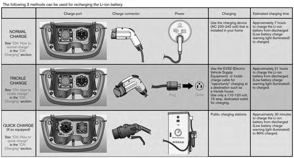
350 CHARGING INFORMATION
2017 LEAF OWNER S MANUAL. For your safety, read carefully and keep in this vehicle.
 2017 LEAF OWNER S MANUAL For your safety, read carefully and keep in this vehicle. FOREWORD Welcome to the growing family of new NISSAN owners. This vehicle is delivered to you with confidence. It was
Black plate (27,1) Index 14 北米Model "A3180BE-B" EDITED: 2014/ 2/ 7
 Index 14 北米Model A3180BE-B EDITED: 2014/ 2/ 7") Index 14 14-2 Index A Abbreviation... 3 ABS (Anti-lock Brake System)... 7-20 Warning light... 3-15, 7-21 Accessories... 5-2, 11-36 Accessory power outlet... 6-10 Active head restraint... 1-6 Air cleaner
Index 14 14-2 Index A Abbreviation... 3 ABS (Anti-lock Brake System)... 7-20 Warning light... 3-15, 7-21 Accessories... 5-2, 11-36 Accessory power outlet... 6-10 Active head restraint... 1-6 Air cleaner
General information S00AK & California proposition 65 warning
 General information S00AK & California proposition 65 warning S00AK02 WARNING Engine exhaust, some of its constituents, and certain vehicle components contain or emit chemicals known to the State of California
NISSAN CUSTOMER CARE PROGRAM
 NISSAN CUSTOMER CARE PROGRAM NISSAN CARES... Both NISSAN and your NISSAN dealer are dedicated to serving all your automotive needs. Your satisfaction with your vehicle and your NISSAN dealer are our primary
SECTION 1 1 FEATURES ON NEW TOYOTA RAV4 EV. Overview of instruments and controls
 FEATURES ON NEW TOYOTA RAV4 EV Overview of instruments and controls SECTION 1 1 Instrument panel overview..................................... 2 Instrument cluster overview....................................
2011 ALTIMA HyBRID. Quick Reference Guide
 21 ALTIMA HyBRID Quick Reference Guide 02 03 15 06 04 05 07 09 10 08 16 17 11 12 13 14 02 03 04 05 POWER METER* LOW TIRE PRESSURE WARNING LIGHT HIGH VOLTAGE BATTERY STATUS METER HEADLIGHT AND TURN SIGNAL
(1,1) Index 14 北米Model "A1330BE-B" EDITED: 2017/ 11/ 30
 Index 14 北米Model A1330BE-B EDITED: 2017/ 11/ 30") Index 14 14-2 Index A Abbreviation... 3 ABS (Anti-lock Brake System)... 7-33 Warning light... 3-20 Access key fob... 2-3 Warning light... 3-25 Accessories... 11-37 Accessory power outlet... 6-7 Air cleaner
Index 14 14-2 Index A Abbreviation... 3 ABS (Anti-lock Brake System)... 7-33 Warning light... 3-20 Access key fob... 2-3 Warning light... 3-25 Accessories... 11-37 Accessory power outlet... 6-7 Air cleaner
Index. Abbreviation list Alphabetical index What to do if
 Index Abbreviation list... 478 Alphabetical index... 479 What to do if...... 489 477 Abbreviation list Abbreviation/Acronym list ABBREVIATIONS ABS ACC ALR CRS DISP ECU EDR ELR GAWR GVWR I/M LATCH LED LSD
Index. Abbreviation list Alphabetical index What to do if
 Index Abbreviation list... 470 Alphabetical index... 471 What to do if...... 481 469 Abbreviation list Abbreviation/Acronym list ABBREVIATIONS ABS ACC ALR CRS DISP ECU EDR ELR GAWR GVWR I/M LATCH LED LSD
2011 Infiniti QX Quick Reference Guide
 21 Infiniti QX Quick Reference Guide 06 11 07 08 12 13 04 09 Behind steering wheel on column 11 05 10 03 14 17 18 19 20 21 15 16 INSTRUMENT BRIGHTNESS control SwITcH* HEADLIGHT AND TURN SIGNAL SwITcH windshield
Quick Reference Guide
 21 XTERRA Quick Reference Guide 04 03 12 05 06 07 10 13 14 08 09 15 19 11 16 17 18 03 04 05 LOW TIRE PRESSURE WARNING LIGHT TRIP COMPUTER* INSTRUMENT BRIGHTNESS CONTROL / TRIP CHANGE BUTTON* HEADLIGHT
InformationProvidedby:
 Foreword Welcome to the growing family of new NISSAN owners. This vehicle is delivered to you with confidence. It was produced using the latest techniques and strict quality control. This manual was prepared
2013LEAF QUIck REFERENcE GUIDE _13_Leaf_QRG_Cover_ indd 2 12/19/12 9:38 AM
 23LEAF Quick Reference Guide 09 04 03 05 10 06 07 08 23 11 12 13 14 15 16 17 18 19 24 25 20 21 26 22 27 28 30 29 30 31 POWER METER HEADLIGHT AND TURN SIGNAL CONTROL 03 LI-ION BATTERY TEMPERATURE GAUGE*
2014 cube OWNER S MANUAL. InformationProvidedby: For your safety, read carefully and keep in this vehicle.
 2014 cube OWNER S MANUAL For your safety, read carefully and keep in this vehicle. WHEN READING THE MANUAL This manual includes information for all options available on this model. Therefore, you may
2012 Nissan LEAF Specifications
 2012 Nissan LEAF pecifications pecifications are based on latest product information available at the time of release Mechanical Mechanical High-response 80 kw AC synchronous electric motor Laminated 24
WARNING IMPORTANT SAFETY INFORMA- TION REMINDERS FOR SAFETY!
 Foreword Welcome to the growing family of new NISSAN owners. This vehicle is delivered to you with confidence. It was produced using the latest techniques and strict quality control. This manual was prepared
Black plate (31,1) Index 14 北米Model "A2530BE-B" EDITED: 2016/ 7/ 27
 Index 14 北米Model A2530BE-B EDITED: 2016/ 7/ 27") Index 14 14-2 Index A Abbreviation... 3 ABS (Anti-lock Brake System)... 7-33 Warning light... 3-19 Access key... 2-10 Warning indicator... 3-25 Accessories... 11-40 Accessory power outlet... 6-10 Air cleaner
Index 14 14-2 Index A Abbreviation... 3 ABS (Anti-lock Brake System)... 7-33 Warning light... 3-19 Access key... 2-10 Warning indicator... 3-25 Accessories... 11-40 Accessory power outlet... 6-10 Air cleaner
Customer Experience Center Pocket Reference Guide
 Customer Experience Center 1-800-331-4331 2007 Pocket Reference Guide MN 00452-PRG07-COR Printed in USA 6/06 17 2007 Corolla This Pocket Reference Guide is a summary of basic vehicle operations. It contains
The following procedures should be observed to ensure safe driving.
 Driving the vehicle The following procedures should be observed to ensure safe driving. n Starting the hybrid system ( P. 162) n Driving STEP 1 With the brake pedal depressed, shift the shift lever to
2015 Scion iq Quick Reference Guide
 2015 Scion iq Quick Reference Guide 2015 Scion iq This Quick Reference Guide is a summary of basic vehicle operations. It contains brief descriptions of fundamental operations so you can locate and use
WARNING IMPORTANT SAFETY INFORMA- TION REMINDERS FOR SAFETY!
 Foreword Welcome to the growing family of new NISSAN owners. This vehicle is delivered to you with confidence. It was produced using the latest techniques and strict quality control. This manual was prepared
tc 2011 QUICK REFERENCE GUIDE GET INFORMED. ROLL.
 tc 2011 QUICK REFERENCE GUIDE GET INFORMED. ROLL. 2011 Scion tc This Quick Reference Guide is a summary of basic vehicle operations. It contains brief descriptions of fundamental operations so you can
requirements, assisting you in the safe operation of your vehicle. WARNING IMPORTANT SAFETY INFORMA- TION REMINDERS FOR SAFETY!
 Foreword Welcome to the growing family of new NISSAN owners. This vehicle is delivered to you with confidence. It was produced using the latest techniques and strict quality control. This manual was prepared
Indicators and warning lights
 Indicators and warning lights The indicator and warning lights on the instrument cluster and instrument panel inform the driver of the status of the vehicle s various systems. Instrument cluster Instrument
2007 VERSA QUICK REFERENCE GUIDE. Shift_space
 2007 VERSA QUICK REFERENCE GUIDE Shift_space 04 05 06 12 13 14 11 07 08 15 09 10 HEADLIGHT AND TURN SIGNAL CONTROL 04 TWIN TRIP ODOMETER 07 INSTRUMENT BRIGHTNESS CONTROL* 10 HOOD RELEASE* 13 AUDIO SYSTEM
WARNING IMPORTANT SAFETY INFORMA- TION REMINDERS FOR SAFETY!
 Foreword Welcome to the growing family of new NISSAN owners. This vehicle is delivered to you with confidence. It was produced using the latest techniques and strict quality control. This manual was prepared
READ FIRST THEN DRIVE SAFELY
 Foreword GUID-E7E6B9D7-70D5-46FD-8070-D86AD68B3005 Welcome to the growing family of new NISSAN owners. This vehicle is delivered to you with confidence. It was produced using the latest techniques and
note remote key & key blade
 remote key & key blade Locks the doors and trunk and arms the alarm. If the car is locked with the remote key while the power retractable hard top is down, the double locking feature activates after approximately
READ FIRST THEN DRIVE SAFELY
 Foreword Welcome to the growing family of new NISSAN owners. This vehicle is delivered to you with confidence. It was produced using the latest techniques and strict quality control. This manual was prepared
note remote key & key blade
 remote key & key blade Locks the doors and tailgate, and arms the alarm. Unlocks the doors and tailgate A and disarms the alarm. Unlocks (but does not open) the tailgate. key blade Used to lock/unlock
Side view. Fig. 1 Vehicle side overview.
 Side view Fig. 1 Vehicle side overview. Key to fig. 1: (1) Fuel filler flap (2) Roof antenna (3) Outside door handles (4) Outside mirror Additional turn signal light (5) Lift points for the jack Front
2014 LEAF QUICK REFERENCE GUIDE
 24 LEAF QUICK REFERENCE GUIDE 09 04 03 05 10 06 07 08 23 11 12 13 14 15 16 17 18 19 24 25 20 21 26 22 27 28 30 29 30 31 POWER METER HEADLIGHT AND TURN SIGNAL CONTROL 03 LI-ION BATTERY TEMPERATURE GAUGE*
Illustrated index. & Exterior
 10 Illustrated index & Exterior 1) Engine hood (page 11-5) 2) Wiper (page 3-97) 3) Headlight (page 3-89) 4) Replacing bulbs (page 11-36) 5) Moonroof (page 2-42) 6) Roof rails (page 8-14) 7) Outside mirror
volvo s40 Quick Guide
 volvo s40 Quick Guide WELCOME TO THE GLOBAL FAMILY OF VOLVO OWNERS! Getting to know your new vehicle is an exciting experience. Please browse through this Quick Guide to get the full benefits from your
Steering Wheel and Nearby Controls
 VISUAL INDEX Quickly locate items in the vehicle s interior. Visual Index Steering Wheel and Nearby Controls 13 7 1 8 9 2 3 4 14 11 10 6 5 12 1 Lights/turn signals/lanewatch button* 2 SEL/RESET knob* Brightness
WARNING IMPORTANT SAFETY INFORMA- TION REMINDERS FOR SAFETY!
 Foreword Welcome to the growing family of new NISSAN owners. This vehicle is delivered to you with confidence. It was produced using the latest techniques and strict quality control. This manual was prepared
Table of contents. Seat, seatbelt and SRS airbags 1. Keys and doors 2. Instruments and controls. Climate control 4. Audio 5. Interior equipment 6
 Table of contents Seat, seatbelt and SRS airbags 1 Keys and doors 2 Instruments and controls 3 Climate control 4 Audio 5 Interior equipment 6 Starting and operating 7 Driving tips 8 In case of emergency
Quick Guide. volvo C30
 volvo C30 Quick Guide WELCOME TO THE GLOBAL FAMILY OF VOLVO OWNERS! Getting to know your new vehicle is an exciting experience. This Quick Guide provides a brief overview of the most common features and
Light condition and operation Windshield glass condition Wiper blade condition Paint condition and corrosion Fluid leaks Door and hood lock condition
 GENERAL CHECKS Engine Compartment The following should be checked regularly: Engine oil level and condition Transmission fluid level and condition Brake fluid level Clutch fluid level Engine coolant level
2013 Scion xd Quick Reference Guide
 2013 Scion xd Quick Reference Guide 2013 INDEX Scion xd OVERVIEW Engine maintenance 7 This Quick Reference Guide is a summary of basic vehicle operations. It contains brief descriptions of fundamental
READ FIRST THEN DRIVE SAFELY
 FOREWORD READ FIRST THEN DRIVE SAFELY Welcome to the growing family of new NISSAN owners. This vehicle is delivered to you with confidence. It was produced using the latest techniques and strict quality
volvo C70 quick guide
 volvo C70 quick guide WELCOME TO THE GLOBAL FAMILY OF VOLVO OWNERS! Getting to know your new vehicle is an exciting experience. Please browse through this Quick Guide to get the full benefits from your
InformationProvidedby:
 Foreword Welcome to the growing family of new NISSAN owners. This vehicle is delivered to you with confidence. It was produced using the latest techniques and strict quality control. This manual was prepared
Owner s Manual Supplement
 Owner s Manual Supplement The information contained within this supplement revises the TIRE CHAINS information in the Maintenance and do-it-yourself section of the 2011-2013 Nissan Quest Owner s Manual.
PRIUS QUICK REFERENCE GUIDE CUSTOMER EXPERIENCE CENTER Printed in U.S.A. 6/10 08-TCS QRG10-PRI
 CUSTOMER EXPERIENCE CENTER 1-800-331-4331 PRIUS 2 0 1 0 QUICK REFERENCE GUIDE Printed in U.S.A. 6/10 08-TCS-04342 00505-QRG10-PRI 2010 Prius This Quick Reference Guide is a summary of basic vehicle operations.
WARNING IMPORTANT SAFETY INFORMA- TION REMINDERS FOR SAFETY!
 Foreword Welcome to the growing family of new NISSAN owners. This vehicle is delivered to you with confidence. It was produced using the latest techniques and strict quality control. This manual was prepared
READ FIRST THEN DRIVE SAFELY
 FOREWORD READ FIRST THEN DRIVE SAFELY Welcome to the growing family of new NISSAN owners. This vehicle is delivered to you with confidence. It was produced using the latest techniques and strict quality
2018 Honda Clarity Plug-In Hybrid Emergency Response Guide
 2018 Honda Clarity Plug-In Hybrid Emergency Response Guide Prepared for Fire Service, Law Enforcement, Emergency Medical, and Professional Towing Personnel 2017 American Honda Motor Co., Inc. All Rights
Quick Guide VOLVO S80
 VOLVO S80 Quick Guide WELCOME TO THE GLOBAL FAMILY OF VOLVO OWNERS! Getting to know your new vehicle is an exciting experience. This Quick Guide provides a brief overview of the most common features and
2015 Quick Reference Guide
 05 Quick Reference Guide For detailed operating and safety information, please refer to your Owner s Manual. BASIC OPERATION Lock/ Unlock doors Remote keyless entry system PANIC 4 4 All doors and the rear
READ FIRST THEN DRIVE SAFELY
 FOREWORD READ FIRST THEN DRIVE SAFELY Welcome to the growing family of new NISSAN owners. This vehicle is delivered to you with confidence. It was produced using the latest techniques and strict quality
READ FIRST THEN DRIVE SAFELY
 FOREWORD READ FIRST THEN DRIVE SAFELY Welcome to the growing family of new NISSAN owners. This vehicle is delivered to you with confidence. It was produced using the latest techniques and strict quality
note remote key & key blade
 remote key & key blade Locks the doors and trunk and arms the alarm. If the car is locked with the remote key while the power retractable hard top is down, the double locking feature activates after approximately
Quick GUIDE Web Edition
 XC90 Quick GUIDE Web Edition WELCOME TO THE GLOBAL FAMILY OF VOLVO OWNERS! Getting to know your new vehicle is an exciting experience. This Quick Guide provides a brief overview of the most common features
2015 Quick Reference Guide
 05 Quick Reference Guide For detailed operating and safety information, please refer to your Owner s Manual. BASIC OPERATION Lock/ Unlock doors Remote keyless entry system PANIC Remote transmitter key
2013 Scion tc Quick Reference Guide
 2013 Scion tc Quick Reference Guide 2013 Scion tc This Quick Reference Guide is a summary of basic vehicle operations. It contains brief descriptions of fundamental operations so you can locate and use
2018 Honda Accord Hybrid Emergency Response Guide
 2018 Honda Accord Hybrid Emergency Response Guide Prepared for Fire Service, Law Enforcement, Emergency Medical, and Professional Towing Personnel 2018 American Honda Motor Co., Inc. All Rights Reserved.
2008 Quick Reference Guide
 2008 Quick Reference Guide Interactive Owner s Guide Have a question about the main features of your new Toyota? Find the answers quickly and easily in this Quick Reference Guide, which includes highlights
READ FIRST THEN DRIVE SAFELY
 FOREWORD READ FIRST THEN DRIVE SAFELY Welcome to the growing family of new NISSAN owners. This vehicle is delivered to you with confidence. It was produced using the latest techniques and strict quality
C>r>E: s EMERGENCY RESPONSE GUIDE
 2016+ C>r>E: s EMERGENCY RESPONSE GUIDE This guide is intended only for use by trained and certified rescuers and first responders. It assumes that readers have a comprehensive understanding of how safety
Indicator and warning lamps. Indicator and warning lamps
 can light up in a variety of combinations and colors. See the table for information on causes and how to react. Note whether a lamp comes on alone or in combination with another. Some lamps can light up
2012 VERSA SEDAN OWNER S MANUAL. For your safety, read carefully and keep in this vehicle.
 2012 VERSA SEDAN OWNER S MANUAL For your safety, read carefully and keep in this vehicle. FOREWORD READ FIRST THEN DRIVE SAFELY Welcome to the growing family of new NISSAN owners. This vehicle is delivered
4Runner Runner The adventurous side of life
 unner 2018 unner 2018 The adventurous side of life Toyota Entune 3.0 available only on selected Toyota 2018 models. Desempeño Engine: 4.0 Liters, DOHC, 24 valves EFI dual independent VVT-i, 270-HP @ 5,600
Z OWNER S MANUAL. InformationProvidedby: For your safety, read carefully and keep in this vehicle.
 2016 370Z OWNER S MANUAL For your safety, read carefully and keep in this vehicle. Foreword Welcome to the growing family of new NISSAN owners. This vehicle is delivered to you with confidence. It was
READ FIRST THEN DRIVE SAFELY
 FOREWORD READ FIRST THEN DRIVE SAFELY Welcome to the growing family of new NISSAN owners. This vehicle is delivered to you with confidence. It was produced using the latest techniques and strict quality
2014, Acura RLX Sport Hybrid Emergency Response Guide
 2014, 2016 18 Acura RLX Sport Hybrid Emergency Response Guide Prepared for Fire Service, Law Enforcement, Emergency Medical, and Professional Towing Personnel NOTE: Acura did not produce this model for
2007 MAXIMA QUICK REFERENCE GUIDE. Shift_exhilaration
 2007 MAXIMA QUICK REFERENCE GUIDE Shift_exhilaration 12 05 13 06 07 08 09 10 14 11 15 HEADLIGHT AND TURN SIGNAL CONTROL STEERING WHEEL SWITCHES FOR AUDIO CONTROL 07 OUTSIDE MIRROR CONTROL SWITCH 10 STEERING
2007 ARMADA QUICK REFERENCE GUIDE. Shift_scale
 2007 ARMADA QUICK REFERENCE GUIDE Shift_scale 07 HOOD RELEASE* 09 08 STEERING WHEEL TILT ADJUSTMENT* 10 09 CONTROL PANEL DISPLAY 05 06 11 12 10 AUDIO SYSTEM 13 07 08 11 FRONT-PASSENGER AIR BAG STATUS LIGHT
Table of contents. Seat, seatbelt and SRS airbags 1. Keys and doors 2. Instruments and controls. Climate control 4. Audio 5. Interior equipment 6
 Table of contents Seat, seatbelt and SRS airbags 1 Keys and doors 2 Instruments and controls 3 Climate control 4 Audio 5 Interior equipment 6 Starting and operating 7 Driving tips 8 In case of emergency
WARNING IMPORTANT SAFETY INFORMA- TION REMINDERS FOR SAFETY!
 Foreword Welcome to the growing family of new NISSAN owners. This vehicle is delivered to you with confidence. It was produced using the latest techniques and strict quality control. This manual was prepared
requirements, assisting you in the safe operation of your vehicle. WARNING IMPORTANT SAFETY INFORMA- TION REMINDERS FOR SAFETY!
 Foreword Welcome to the growing family of new NISSAN owners. This vehicle is delivered to you with confidence. It was produced using the latest techniques and strict quality control. This manual was prepared
Quick Guide. volvo XC90
 volvo XC90 Quick Guide WELCOME TO THE GLOBAL FAMILY OF VOLVO OWNERS! Getting to know your new vehicle is an exciting experience. This Quick Guide provides a brief overview of the most common features and
READ FIRST THEN DRIVE SAFELY
 FOREWORD READ FIRST THEN DRIVE SAFELY Welcome to the growing family of new NISSAN owners. This vehicle is delivered to you with confidence. It was produced using the latest techniques and strict quality
Engine 2.5 litre 3.0 litre. Capacity inch³ (2495 cm³) 181 inch³ (2967 cm³) Bore inch (8.16 cm) inch (8.90cm)
 181 inch³ (2967 cm³) Bore inch (8.16 cm) inch (8.90cm)") 8 Specifications Specifications 8-1 Vehicle data Engine 2.5 litre 3.0 litre Type.................................................. V6, dual overhead camshafts, 4valves/cylinder V6, dual overhead camshafts,
8 Specifications Specifications 8-1 Vehicle data Engine 2.5 litre 3.0 litre Type.................................................. V6, dual overhead camshafts, 4valves/cylinder V6, dual overhead camshafts,
Important information about this manual
 Important information about this manual Safety and vehicle damage warnings Safety symbol Throughout this manual, you will see safety and vehicle damage warnings. You must follow these warnings carefully
FORD ECOSPORT Quick Reference Guide
 FORD ECOSPORT Quick Reference Guide About This Quick Reference Guide We have created this guide to help you get to know certain features of your vehicle quickly. It only contains basic instructions to
READ FIRST THEN DRIVE SAFELY
 FOREWORD Your INFINITI represents a new way of thinking about vehicle design. It integrates advanced engineering and superior craftsmanship with a simple, refined aesthetic sensitivity associated with
READ FIRST THEN DRIVE SAFELY
 FOREWORD READ FIRST THEN DRIVE SAFELY Welcome to the growing family of new NISSAN owners. This vehicle is delivered to you with confidence. It was produced using the latest techniques and strict quality
1 Green light: Vehicle is locked. 2 Yellow light: Vehicle is unlocked. 3 Flashing red light: Someone may be in the
 REMOTE KEY WITH PCC* personal car communicator Locks the doors and trunk and arms the alarm. Unlocks the doors and trunk, and disarms the alarm A. Trunk (press once to unlock, press twice to open trunk
2007 XTERRA QUICK REFERENCE GUIDE. Shift_your limits
 2007 XTERRA QUICK REFERENCE GUIDE Shift_your limits 08 09 10 04 11 12 13 09 CLIMATE CONTROLS 06 14 10 FRONT-PASSENGER AIRBAG STATUS LIGHT 11 E-LOCK SWITCH 07 12 HILL DESCENT CONTROL SWITCH HEADLIGHT AND
Honda Clarity Electric Emergency Response Guide
 2017 18 Honda Clarity Electric Emergency Response Guide Prepared for Fire Service, Law Enforcement, Emergency Medical, and Professional Towing Personnel Supersedes 2017 Honda Clarity Electric Emergency
FORD ECOSPORT Quick Reference Guide
 FORD ECOSPORT Quick Reference Guide About This Quick Reference Guide We have created this guide to help you get to know certain features of your vehicle quickly. It only contains basic instructions to
requirements, assisting you in the safe operation of your vehicle. WARNING IMPORTANT SAFETY INFORMA- TION REMINDERS FOR SAFETY!
 Foreword Welcome to the growing family of new NISSAN owners. This vehicle is delivered to you with confidence. It was produced using the latest techniques and strict quality control. This manual was prepared
ACCENT AIR CONDITIONING HOOD PROTECTOR CARGO TRAY ACCESSORY FRAME PREMIUM ALL-WEATHER FLOOR LINERS
 ACCENT 2017 2017 ACCENT HOOD PROTECTOR Help prevent dents and scratches caused by road and vehicle debris with an attractive plastic hood protector. AIR CONDITIONING Stay cool all summer long with factory
READ FIRST THEN DRIVE SAFELY
 FOREWORD READ FIRST THEN DRIVE SAFELY Welcome to the growing family of new NISSAN owners. This vehicle is delivered to you with confidence. It was produced using the latest techniques and strict quality
WARNING IMPORTANT SAFETY INFORMA- TION REMINDERS FOR SAFETY!
 Foreword Welcome to the growing family of new NISSAN owners. This vehicle is delivered to you with confidence. It was produced using the latest techniques and strict quality control. This manual was prepared
Customer Experience Center Pocket Reference Guide
 Customer Experience Center 1-800-331-4331 2007 Pocket Reference Guide MN 00452-PRG07-4RUN Printed in USA 07/06 2007 4Runner This Pocket Reference Guide is a summary of basic vehicle operations. It contains
2016 MICRA OWNER S MANUAL. For your safety, read carefully and keep in this vehicle.
 2016 MICRA OWNER S MANUAL For your safety, read carefully and keep in this vehicle. FOREWORD READ FIRST THEN DRIVE SAFELY Welcome to the growing family of new NISSAN owners. This vehicle is delivered to
READ FIRST THEN DRIVE SAFELY
 FOREWORD READ FIRST THEN DRIVE SAFELY Welcome to the growing family of new NISSAN owners. This vehicle is delivered to you with confidence. It was produced using the latest techniques and strict quality
READ FIRST THEN DRIVE SAFELY
 FOREWORD READ FIRST THEN DRIVE SAFELY Welcome to the growing family of new NISSAN owners. This vehicle is delivered to you with confidence. It was produced using the latest techniques and strict quality
C>r>E: X EMERGENCY RESPONSE GUIDE
 2016 C>r>E: X EMERGENCY RESPONSE GUIDE This guide is intended only for use by trained and certified rescuers and first responders. It assumes that readers have a comprehensive understanding of how safety
2015 Yaris Liftback Quick Reference Guide
 2015 Yaris Liftback Quick Reference Guide 2015 INDEX Yaris Liftback OVERVIEW Engine maintenance 7 This Quick Reference Guide is a summary of basic vehicle operations. It contains brief descriptions of
For your safety, read carefully and keep in this vehicle Infiniti EX Owner s Manual
 For your safety, read carefully and keep in this vehicle. 2011 Infiniti EX Owner s Manual FOREWORD Your INFINITI represents a new way of thinking about vehicle design. It integrates advanced engineering
2013 NV200 COMPACT CARGO
 2013 NV200 COMPACT CARGO OWNER S MANUAL For your safety, read carefully and keep in this vehicle. FOREWORD READ FIRST THEN DRIVE SAFELY Welcome to the growing family of new NISSAN owners. This vehicle
2018 LEAF QUICK REFERENCE GUIDE
 208 LEAF QUICK REFERENCE GUIDE 4 5 3 2 4 2 3 5 6 7 6 0 7 20 8 2 8 9 9 24 23 22 Vehicle Information Display*/ Power Meter/Li-ion Battery Temperature Gauge 2 Li-ion Battery Available Charge Gauge/Driving
2013 LEAF. First Responder s Guide
 2013 LEAF First Responder s Guide 1 Foreword This manual describes first response operations and related warnings for this vehicle. This vehicle is an electrically driven car equipped with a high voltage
2016 MURANO OWNER S MANUAL. For your safety, read carefully and keep in this vehicle.
 2016 MURANO OWNER S MANUAL For your safety, read carefully and keep in this vehicle. FOREWORD READ FIRST THEN DRIVE SAFELY Welcome to the growing family of new NISSAN owners. This vehicle is delivered
READ FIRST THEN DRIVE SAFELY
 FOREWORD READ FIRST THEN DRIVE SAFELY Welcome to the growing family of new NISSAN owners. This vehicle is delivered to you with confidence. It was produced using the latest techniques and strict quality
2013 VERSA SEDAN OWNER S MANUAL. safety, read carefully and keep in this vehicle.
 2013 VERSA SEDAN OWNER S MANUAL For your safety, read carefully and keep in this vehicle. FOREWORD READ FIRST THEN DRIVE SAFELY Welcome to the growing family of new NISSAN owners. This vehicle is delivered
2017 Acura MDX Sport Hybrid Emergency Response Guide. Prepared for Fire Service, Law Enforcement, Emergency Medical, and Professional Towing Personnel
 2017 Acura MDX Sport Hybrid Emergency Response Guide Prepared for Fire Service, Law Enforcement, Emergency Medical, and Professional Towing Personnel 2017 American Honda Motor Co., Inc. All Rights Reserved.