Positioning axes DMES
|
|
|
- Dylan Flynn
- 5 years ago
- Views:
Transcription
1 Positioning axes DMES
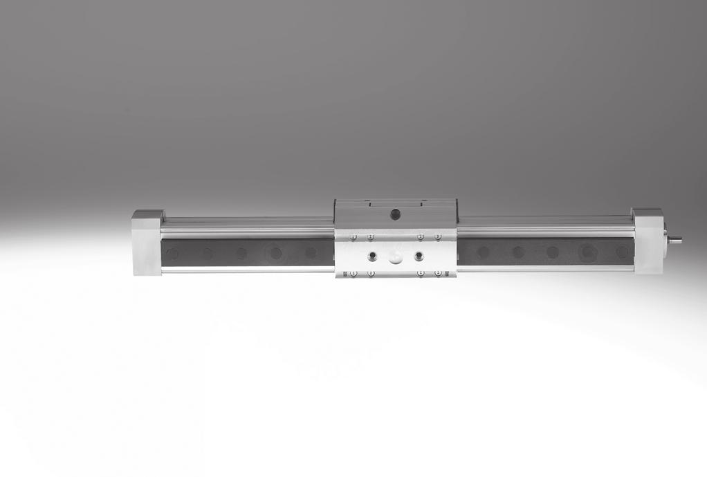
2 Positioning axes DMES Key features At a glance General Properties Range of applications DMES positioning axes are mechanical linear drives that are specially designed for movements involving high forces. The mechanical interfaces are compatible with the spindle axis DGE-SP. High mechanical torques High feed forces up to 3000 N Self-retarding lead-screw spindle Compact dimensions Cost optimised Alternatively: without guide with recirculating ball bearing guide KF For format adjustment: in printing, paper and foil wrapping machines in packaging machines in feed technology Application examples Adjusting sorting conveyors Programming formats for paper or foil cutting machines The technology in detail Positioning axis page 4 Motor page Motor unit MTR-DCI Intelligent servo motor EMMS-ST Servo motor EMME-AS, EMMS-AS 1 Mechanical interfaces are identical to spindle axes DGE- -SP 2 KF: Recirculating ball bearing guide 3 Slot for proximity sensor 4 Lead-screw spindle, for use with high forces The lead-screw spindle is self-retarding, which means that slow movements cannot be excluded in the event of vibration. The entire system with intelligent motor unit MTR-DCI is self-locking. A range of specially adapted complete solutions is available for the positioning axes DMES and the motors. Two motor interfaces are available: Axial motor interface Parallel motor interface 2 Internet: Subject to change 2018/05
 or extended slide (GV) For higher loads For high guide precision Protected version DMES-GA With standard slide (GK) Guide and slide are fitted with a cover to protect against the ingress")
3 Positioning axes DMES Key features Wide choice of variants Basic design DMES, without guide For connection to an existing guide For small loads Recirculating ball bearing guide DMES-KF With standard slide (GK) or extended slide (GV) For higher loads For high guide precision Protected version DMES-GA With standard slide (GK) Guide and slide are fitted with a cover to protect against the ingress of particles from above and from the side Guide characteristics The specifications shown in the table are maximum values. The precise values for each of the variants can be found in the relevant technical data in the catalogue. Basic design DMES Size Working stroke [mm] Speed Repetition accuracy [m/s] [mm] [N] Feed force Forces and torques Page/ Internet Fy [N] Fz [N] Mx [Nm] My [Nm] Mz [Nm] Recirculating ball bearing guide DMES-KF /05 Subject to change Internet: 3
4 Positioning axes DMES, without guide Peripherals overview Variants and accessories Type/Order code Description Page/Internet 1 Positioning axis DMES 2 Intelligent servo unit and parallel kit U 3 Intelligent servo unit and axial kit AX 4 Slot cover B/S 5 Proximity sensor SMT-8 6 Connecting cable KM8 7 Slot nut for mounting slot Y 8 Central support M 9 Foot mounting F Electromechanical axis without guide 6 Complete package for parallel motor attachment, comprising parallel kit and intelligent 14 motor unit MTR-DCI Complete package for axial motor attachment, comprising axial kit and intelligent motor 14 unit MTR-DCI For protecting against ingress of dirt 48 For providing a proximity signal or safety sensing 47 For proximity sensor 47 For mounting attachments 48 For mounting the axis 45 For mounting the axis (can only be attached to end cap, must be combined with central support) 45 -H- Note Servo, stepper motors and the corresponding mounting kits must be ordered separately page 41 4 Internet: Subject to change 2018/05
5 Positioning axes DMES, without guide Type code Type DMES AX : ZUB 2Y 2M DMES Positioning axis Size Stroke [mm] Motor unit AX U Intelligent servo unit and axial kit Intelligent servo unit and parallel kit Accessories ZUB Accessories supplied loose Slot cover S B Sensor slot Mounting slot Slot nut Y For mounting slot Central support M Central support Foot mounting F Foot mounting 2018/05 Subject to change Internet: 5
6 Positioning axes DMES, without guide Technical data Function -W- -N- Size T- Stroke length mm General technical data Size Design Electromechanical linear axis with lead-screw spindle Guide None Assembly position Any Working stroke [mm] Max. feed force F x [N] Max. driving torque [Nm] Max. no-load driving torque 1) [Nm] Max. radial force 2) [N] Max. speed [m/s] 0.05 Max. acceleration [m/s 2 ] 2.5 Repetition accuracy [mm] Positioning rigidity [N/mm] Duty cycle [%] 100 Reversing backlash 3) [mm] 0.1 1) Measured at a speed of 200 rpm. 2) On drive shaft 3) In new condition Operating and environmental conditions Ambient temperature 1) [ C] Protection class IP40 1) Note operating range of proximity sensors Weights [kg] Size Basic weight with 0 mm stroke 1) Additional weight per 100 mm stroke Moving load ) Without coupling housing 6 Internet: Subject to change 2018/05
7 Positioning axes DMES, without guide Technical data Mass moment of inertia Size J 0 [kg cm 2 ] j H per metre stroke [kg cm 2 /m] j L per kg working load [kg cm 2 /Kg] The mass moment of inertia J A of the entire axis is calculated as follows: J A = J 0 + j H x working stroke [m] + j L x m working load [kg] Spindle Size Diameter [mm] Pitch [mm/rev.] Materials Sectional view Positioning axis 1 Cover Wrought aluminium alloy, anodised 2 Spindle Steel 3 Piston, driver Wrought aluminium alloy, anodised 4 Profile Wrought aluminium alloy, anodised 5 Cover strip High-alloy stainless steel 2018/05 Subject to change Internet: 7
8 Positioning axes DMES, without guide Technical data Characteristic load values The indicated forces refer to the centre line of the internal diameter of the profile. They must not be exceeded during dynamic operation. Special attention must be paid to the cushioning phase. If the axis is subjected to more than two of the indicated forces simultaneously, the following equation must be satisfied in addition to the indicated maximum loads: Fy Fz Mx My Mz 1 Fy max. Fz max. Mx max. My max. Mz max. -H- Note Positioning axes DMES without guide are not designed to absorb lateral forces or torques on the slide. Permissible forces and torques Size Fy max. [N] Fz max. [N] Mx max. [Nm] Mymax. [Nm] Mz max. [Nm] nd moment of area F z F y I y I z Size Iy [cm 4 ] Iz [cm 4 ] H- Note Sizing software PositioningDrives 8 Internet: Subject to change 2018/05
9 Positioning axes DMES, without guide Technical data Maximum permissible feed force F as a function of the feed speed v DMES-18 DMES-25 F [N] F [N] v [mm/s] v [mm/s] DMES-40 DMES-63 F [N] F [N] v [mm/s] v [mm/s] Recommended operating range Permissible operating range (duty cycle 50% recommended) 2018/05 Subject to change Internet: 9
10 Positioning axes DMES, without guide Technical data Maximum permissible driving torque M as a function of n (rpm) DMES-18 DMES-25 M [Nm] M [Nm] n [rpm] n [rpm] DMES-40 DMES-63 M [Nm] M [Nm] n [rpm] n [rpm] Recommended operating range Permissible operating range (duty cycle 50% recommended) Driving torque M as a function of the feed force F Speed as a function of the feed speed v n [rpm] v [mm/s] DMES-18 DMES-25 DMES-40 DMES Internet: Subject to change 2018/05
11 Positioning axes DMES, without guide Technical data Dimensions Size 18 Download CAD data Size 25/40/63 1 Coupling housing 2 Coupling 3 Centring hole for foot mounting HP 4 Lubrication opening + = plus stroke length Size B1 B3 B4 B5 B6 B11 B12 B14 D1 D2 D3 D4 D5 D6 D7 H1 H2 H h7 g7 H M5 32 M M6 48 M M8 72 M Size H4 H5 J2 L1 L2 L3 L6 L7 L8 L9 L11 L13 T1 T2 T ) 2) ) When combined with motor unit MTR-DCI with gear reduction 7:1. 2) When combined with motor unit MTR-DCI with gear reduction 14: /05 Subject to change Internet: 11
12 Positioning axes DMES, without guide Technical data Dimensions Profile Download CAD data Size 18 Size 25 Size 40 Size 63 2 Sensor slot for proximity sensor 6 Mounting slot for slot nut NST 12 Internet: Subject to change 2018/05


13 Positioning axes DMES, without guide Ordering data Modular products Order processing for positioning axis DMES in combination with intelligent motor unit MTR-DCI 1 Ordering positioning axis DMES Ordering table page 15 3 Ordering intelligent motor unit MTR-DCI Ordering table page 39 The drive unit and corresponding accessories are configured in the ordering table for the positioning axis DMES. The code AX or U is used to specify whether an intelligent motor unit MTR- DCI and an axial or a parallel kit are required for the positioning axis. The motor unit design must be defined separately. The motor unit order code determined from table 2 must now be completed with the gear unit and parameterisation interface codes. The module number of the intelligent motor unit must not be specified when ordering with order code AX or U. It is determined automatically. 2 Permissible combinations with intelligent motor unit MTR-DCI 4 Order example Positioning axis DMES-18- DMES-25- DMES-40- Motor unit MTR-DCI-32S-VCSC-E MTR-DCI-42S-VCSC-E MTR-DCI-52S-VCSC-E Part No. Type Positioning axis DMES DMES AX:ZUB-2S2Y1M1F Intelligent motor unit MTR-DCI MTR-DCI-42S-VCSC-EG7-R2IO -H- Note Servo, stepper motors and the corresponding mounting kits must be ordered separately page /05 Subject to change Internet: 13
14 Positioning axes DMES, without guide Ordering data Modular products Order code Mandatory data -H- -H- Note The insertion point for the proximity sensor is located on the right-hand side of the positioning axis. O U V H R L top underneath front rear right left Order code Options Motor unit Parallel kit U Motor unit Axial kit AX B/S page 48 page 48 Y M F 14 Internet: Subject to change 2018/05
15 Positioning axes DMES, without guide Ordering data Modular products Ordering table Size Conditions 0M Module No Function Positioning axis without guided slide DMES DMES Size Stroke [mm] O Motor unit Axial kit and motor unit (enclosed separately) 1 -AX Parallel kit and motor unit (enclosed separately) 1 U Accessories Supplied separately :ZUB- :ZUB- Slot cover Sensor slot 1 10 S Mounting slot 1 10 B Slot nut Mounting slot 1 10 Y Central support 1 10 M Foot mounting 1 10 F Code Enter code 1 AX, U Order processing for intelligent motor unit MTR-DCI page 39. M O Mandatory data Options Transfer order code DMES : ZUB MTR-DCI- S- SC-E - IO 2018/05 Subject to change Internet: 15
16 Positioning axes DMES-KF, with recirculating ball bearing guide Peripherals overview 1 2 SIEN M8B Z S K L aj aa ab ac ad 16 Internet: Subject to change 2018/05
17 Positioning axes DMES-KF, with recirculating ball bearing guide Peripherals overview Variants and accessories Type/Order code Description GK/GV GA Page/Internet 1 Positioning axis DMES 2 Sensor retainer T 3 Inductive proximity sensor SIEN 4 Switching lug L 5 Motor unit and parallel kit U 6 Motor unit and axial kit AX 7 Slot nut for slide X 8 Centring sleeves Z 9 Slot cover B/S aj Proximity sensor SMT-8 aa Connecting cable KM8 ab Slot nut for mounting slot Y ac Central support M ad Foot mounting F Electromechanical axis with spindle and recirculating ball bearing guide Adapter for mounting the inductive proximity sensors on the axis For providing a proximity signal or safety sensing For sensing the slide position with inductive proximity sensors Complete package for parallel motor attachment, comprising parallel kit and intelligent motor unit MTR-DCI Complete package for axial motor attachment, comprising axial kit and intelligent motor unit MTR-DCI For mounting loads and attachments on the slide For centring loads and attachments on the slide For protecting against ingress of dirt For providing a proximity signal or safety sensing For proximity sensor For mounting attachments For mounting the axis For mounting the axis (can only be attached to end cap, must be combined with central support) GK: Standard slide GV: Extended slide GA: Protected version -H- Note Servo, stepper motors and the corresponding mounting kits must be ordered separately page /05 Subject to change Internet: 17
18 Positioning axes DMES-KF, with recirculating ball bearing guide Type code Type DMES KF GK SH AX DMES Positioning axis Size Stroke [mm] Guide KF Recirculating ball bearing guide Slide GK GV GA Standard slide Extended slide Protected version Slide attachment position SV Front SH Rear Additional slide KL Left KR Right Motor unit AX Motor unit and axial kit U Motor unit and parallel kit 18 Internet: Subject to change 2018/05
19 Positioning axes DMES-KF, with recirculating ball bearing guide Type code : ZUB 2X 2M Z 2T L Accessories ZUB Accessories supplied loose Slot cover S B Sensor slot Mounting slot Slot nut Y X For mounting slot For slide Central support M Central support Foot mounting F Foot mounting Centring sleeves Z For slide Mounting bracket T For inductive proximity sensors Switching lug L Switching lug 2018/05 Subject to change Internet: 19
20 Positioning axes DMES-KF, with recirculating ball bearing guide Technical data Function -W- -N- Size T- Stroke length 50 1,800 mm General technical data Size Design Electromechanical linear axis with lead-screw spindle Guide With recirculating ball bearing guide Assembly position Any Working stroke [mm] Max. feed force F x [N] Max. driving torque [Nm] Max. no-load driving torque 1) [Nm] Max. radial force 2) [N] Max. speed [m/s] 0.05 Max. acceleration [m/s 2 ] 2.5 Repetition accuracy [mm] Positioning rigidity [N/mm] Duty cycle [%] 100 Reversing backlash 3) [mm] 0.1 1) Measured at a speed of 200 rpm. 2) On drive shaft 3) In new condition Operating and environmental conditions Ambient temperature 1) [ C] Protection class IP40 1) Note operating range of proximity sensors Weights [kg] Size Basic weight with 0 mm stroke 1) GK GV GA Additional weight per 100 mm stroke GK GV GA Moving load GK GV GA Additional slide KL/KR ) Without coupling housing 20 Internet: Subject to change 2018/05
21 Positioning axes DMES-KF, with recirculating ball bearing guide Technical data Mass moment of inertia Size J 0 GK [kg cm 2 ] GV [kg cm 2 ] GA [kg cm 2 ] j H per metre stroke [kg cm 2 /m] j L per kg working load [kg cm 2 /Kg] j W for additional slide [kg cm 2 ] The mass moment of inertia J A of the entire axis is calculated as follows: J A = J 0 + j H x working stroke [m] + j L x m working load [kg] + i x j W i = Number of additional slides Spindle Size Diameter [mm] Pitch [mm/rev.] Materials Sectional view Positioning axis 1 Cover Wrought aluminium alloy, anodised 2 Spindle Steel 3 Piston, driver Wrought aluminium alloy, anodised 4 Profile Wrought aluminium alloy, anodised 5 Cover strip High-alloy stainless steel Guide rail for KF Hardened steel 2018/05 Subject to change Internet: 21
22 Positioning axes DMES-KF, with recirculating ball bearing guide Technical data Characteristic load values for axis with standard slide GK or protected version GA The indicated forces and torques refer to the centre of the guide rail. They must not be exceeded during dynamic operation. Special attention must be paid to the cushioning phase. If the axis is subjected to more than two of the indicated forces and torques simultaneously, the following equation must be satisfied in addition to the indicated maximum loads: Fy Fz Mx My Mz 1 Fy max. Fz max. Mx max. My max. Mz max. Permissible forces and torques Size Fy max. [N] Fz max. [N] Mx max. [Nm] My max. [Nm] Mz max. [Nm] nd moment of area F z F y I y I z Size Iy [cm 4 ] Iz [cm 4 ] H- Note Sizing software PositioningDrives 22 Internet: Subject to change 2018/05
23 Positioning axes DMES-KF, with recirculating ball bearing guide Technical data Characteristic load values for axis with extended slide GV The indicated forces and torques refer to the centre of the guide rail. They must not be exceeded during dynamic operation. Special attention must be paid to the cushioning phase. If the axis is subjected to more than two of the indicated forces and torques simultaneously, the following equation must be satisfied in addition to the indicated maximum loads: Fy Fz Mx My Mz 1 Fy max. Fz max. Mx max. My max. Mz max. Permissible forces and torques Size Fy max. [N] Fz max. [N] Mx max. [Nm] My max. [Nm] Mz max. [Nm] nd moment of area F z F y I y I z Size Iy [cm 4 ] Iz [cm 4 ] /05 Subject to change Internet: 23
24 Positioning axes DMES-KF, with recirculating ball bearing guide Technical data Deflection of the positioning axis as a function of the working load F and the support span l The following diagrams can be used to determine the deflection of a positioning axis supported externally at both ends (see drawing below). A differentiation is made between two load directions. The axis may also need to be supported with central supports MUP in order to limit deflection in the case of large strokes. Deflection along the y-axis F y F y Deflection along the z-axis F z F z Example showing how to determine deflection f [mm] l [mm] Given: Positioning axis DMES KF- Working stroke = 700 mm Total length of the positioning axis, dimensional drawing mm+175 mm = 875 mm Working load F = 2500 N Support span l = 500 mm To be found: Deflection f Procedure: A support span of 500 mm (see X-axis) and a working load of 2500 N (see characteristic curve) produces a deflection of 0.4 mm. Note: The slide may not be moved under this load as the operating point is in the static area of the diagram. In order to be able to operate the slide dynamically, the support span must be reduced to 400 mm. 2,500 N Impermissible range: The positioning axis may not be used. Static range: The slide must not be moved under load. Static and dynamic range: The slide must be moved under load. 24 Internet: Subject to change 2018/05
25 Positioning axes DMES-KF, with recirculating ball bearing guide Technical data Deflection of the positioning axis as a function of the working load F and the working stroke l Along the y-axis Along the z-axis F y F z DMES-18 DMES-18 f [mm] f [mm] l [mm] l [mm] 0 N 150 N 300 N 450 N 600 N 750 N 900 N Impermissible range Static range Static and dynamic range DMES-25 DMES-25 f [mm] f [mm] l [mm] l [mm] 0 N 500 N 1000 N 1500 N 2000 N 2500 N Impermissible range Static range Static and dynamic range 2018/05 Subject to change Internet: 25
26 Positioning axes DMES-KF, with recirculating ball bearing guide Technical data Deflection of the positioning axis as a function of the working load F and the working stroke l Along the y-axis Along the z-axis F y F z DMES-40 DMES-40 f [mm] f [mm] l [mm] l [mm] 0 N 1000 N 2000 N 3000 N 4000 N Impermissible range Static range Static and dynamic range DMES-63 DMES-63 f [mm] f [mm] l [mm] l [mm] 0 N 1000 N 2000 N 3000 N 4000 N 5000 N 6000 N 6500 N Impermissible range Static range Static and dynamic range 26 Internet: Subject to change 2018/05
27 Positioning axes DMES-KF, with recirculating ball bearing guide Technical data Maximum permissible feed force F as a function of the feed speed v DMES-18 DMES-25 F [N] F [N] v [mm/s] v [mm/s] DMES-40 DMES-63 F [N] F [N] v [mm/s] v [mm/s] Recommended operating range Permissible operating range (duty cycle 50% recommended) 2018/05 Subject to change Internet: 27
28 Positioning axes DMES-KF, with recirculating ball bearing guide Technical data Maximum permissible driving torque M as a function of n (rpm) DMES-18 DMES-25 M [Nm] M [Nm] n [rpm] n [rpm] DMES-40 DMES-63 M [Nm] M [Nm] n [rpm] n [rpm] Recommended operating range Permissible operating range (duty cycle 50% recommended) Driving torque M as a function of the feed force F Speed as a function of the feed speed v n [rpm] v [mm/s] DMES-18 DMES-25 DMES-40 DMES Internet: Subject to change 2018/05
29 Positioning axes DMES-KF, with recirculating ball bearing guide Technical data Dimensions Standard slide GK Size 18 Download CAD data 5 Hole for centring pin ZBS-5 Basic dimensions 11 Size 25/40/63 5 Hole for centring pin ZBH-9 6 Mounting slot for slot nut NSTL 7 Hole for central mounting SLZZ + = plus stroke length Basic dimensions 11 Size B7 B8 B9 D10 D11 H7 H10 H11 L1 L2 L17 L19 T4 T8 ±0.2 G ±0.1 max M M M /05 Subject to change Internet: 29
30 Positioning axes DMES-KF, with recirculating ball bearing guide Technical data Dimensions Standard slide GK Size 40/63 Download CAD data 5 Hole for centring pin ZBH-9 6 Mounting slot for slot nut NSTL + = plus stroke length Size D10 L17 L19 L20 T8 ±0.1 ± M M M Profile Size 18 Size 25 Size 40 Size 63 2 Sensor slot for proximity sensor 6 Mounting slot for slot nut NST 30 Internet: Subject to change 2018/05
31 Positioning axes DMES-KF, with recirculating ball bearing guide Technical data Additional slide KL/KR Size 18 1) 4 Additional slide DMES- -KL/KR 1) Recommended minimum distance for access to lubrication nipple Size 25/40/63 1) 4 Additional slide DMES- -KL/KR 1) Recommended minimum distance for access to lubrication nipple Size L Working stroke reduction with standard slide GK or extended slide GV and additional slide KL/KR L17 = Slide/additional slide length L18 = Distance between both slides 4 Additional slide For a toothed belt axis with additional slide, the working stroke is reduced by the length of the additional slide and the distance between both slides. Example: Type DMES KF-GK KL Working stroke without additional slide = 500 mm L18 = 20 mm L17 = 105 mm Working stroke with additional slide = 375 mm (500 mm 20 mm 105 mm) 2018/05 Subject to change Internet: 31
32 Positioning axes DMES-KF, with recirculating ball bearing guide Technical data Dimensions Extended slide GV Size 18 Download CAD data 4 Lubrication opening 5 Hole for centring pin ZBS-5 + = plus stroke length Basic dimensions Internet: Subject to change 2018/05
33 Positioning axes DMES-KF, with recirculating ball bearing guide Technical data Dimensions Extended slide GV Size 25/40/63 Download CAD data 4 Lubrication opening 5 Hole for centring pin ZBS-9 6 Slot for slot nut NSTL 7 Hole for central mounting SLZZ + = plus stroke length Basic dimensions 11 Size 40 5 Hole for centring pin ZBH-9 6 Mounting slot for slot nut NSTL Size B7 B8 B9 B10 D10 D11 H7 H10 H11 ±0.2 G M M M Size L1 L2 L11 L17 L19 L20 L21 T4 T8 ±0.1 ±0.1 ±0.1 ±0.1 max /05 Subject to change Internet: 33
34 Positioning axes DMES-KF, with recirculating ball bearing guide Technical data Dimensions Protected version GA Size 18 Download CAD data 4 Lubrication opening + = plus stroke length Size 25 4 Lubrication opening + = plus stroke length 34 Internet: Subject to change 2018/05
35 Positioning axes DMES-KF, with recirculating ball bearing guide Technical data Dimensions Protected version GA Size 40 Download CAD data 4 Lubrication opening + = plus stroke length 2018/05 Subject to change Internet: 35


36 Positioning axes DMES-KF, with recirculating ball bearing guide Ordering data Modular products Order processing for positioning axis DMES in combination with intelligent motor unit MTR-DCI 1 Ordering positioning axis DMES Ordering table page 38 3 Ordering intelligent motor unit MTR-DCI Ordering table page 39 The drive unit and corresponding accessories are configured in the ordering table for the positioning axis DMES. The code AX or U is used to specify whether an intelligent motor unit MTR- DCI and an axial or a parallel kit are required for the positioning axis. The motor unit design must be defined separately. The motor unit order code determined from table 2 must now be completed with the gear unit and parameterisation interface codes. The module number of the intelligent motor unit must not be specified when ordering with order code AX or U. It is determined automatically. 2 Permissible combinations with intelligent motor unit MTR-DCI 4 Order example Positioning axis DMES-18- DMES-25- DMES-40- Motor unit MTR-DCI-32S-VCSC-E MTR-DCI-42S-VCSC-E MTR-DCI-52S-VCSC-E Part No. Type Positioning axis DMES DMES KF-GK-SH-AX:ZUB-2S2Y1M1F Intelligent motor unit MTR-DCI MTR-DCI-42S-VCSC-EG7-R2IO -H- Note Servo, stepper motors and the corresponding mounting kits must be ordered separately page Internet: Subject to change 2018/05
37 Positioning axes DMES-KF, with recirculating ball bearing guide Ordering data Modular products Order code Mandatory data DMES- -GK DMES- -GV -H- -H- -H- Note The insertion point for the proximity sensor is located on the right-hand side of the positioning axis. O U V H R L top underneath front rear right left Order code Options T page 48 SIEN M8B Z S K L L Motor unit Parallel kit U Motor unit Axial kit AX X Z B/S page 48 page 48 Y M F 2018/05 Subject to change Internet: 37
38 Positioning axes DMES-KF, with recirculating ball bearing guide Ordering data Modular products Ordering table Size Conditions 0M Module No Code Enter code Function Positioning axis with slide DMES DMES Size Stroke [mm] Guide Recirculating ball bearing guide 1 -KF -KF Slide Standard slide 2 -GK Extended slide 2 -GV Protected version 2 -GA Slide attachment position Slide at front 2 -SV Slide at rear 2 -SH Additional slide Additional slide, standard, at left 3 -KL Additional slide, standard, at right 3 -KR Motor unit Axial kit and motor unit (enclosed separately) 4 -AX Parallel kit and motor unit (enclosed separately) 4 -U Accessories Supplied separately :ZUB- :ZUB- Slot cover Sensor slot 1 10 S Mounting slot 1 10 B Slot nut Mounting slot 1 10 Y Slide X Central support 1 10 M Foot mounting 1 10 F Centring sleeve (pack of 10) Z Mounting bracket for inductive T proximity sensors Switching lug 1 5 L 1 KF Only with slide GK, GV or GA and with slide attachment position SV or SH. 2 GK, GV, GA, SV, SH, X, Z Only with guide KF 3 KL, KR Only with guide KF (recirculating ball bearing guide) and with slide GK or GV 4 AX, U Order processing for intelligent motor unit MTR-DCI page 39 5 T, L Only with slide GK or GV M O Mandatory data Options Transfer order code DMES KF : ZUB MTR-DCI- S-VCSC-E - IO 38 Internet: Subject to change 2018/05
39 Motor units MTR-DCI, intelligent servo motors Ordering data Modular products 2018/05 Subject to change Internet: 39
40 Positioning axes DMES Accessories Motor units MTR-DCI 0M Mandatory data Module No. Motor unit Flange/size Nominal voltage Measuring system Parameterisation interface Motor type Torque class Plug design Gearing unit Electrical connection technology MTR DCI S VC SC E G7 G14 R2 H2 IO CO PB DN Order example MTR DCI 42 S VC SC E G7 R2 IO Ordering table Size Conditions 0M Module No Motor unit Motor unit MTR MTR Motor type DC servo motor with integrated position controller -DCI -DCI Flange/size Torque class Standard torque class S S Nominal voltage [V] 24 DC -VC Plug design Straight plug SC SC Measuring system Encoder -E -E Gearing unit Integrated planetary gearing i = 6.75 G7 Integrated planetary gearing i = G14 Parameterisation interface RS232 interface -R2 RS232 interface + control panel -H2 Electrical connection technology I/O interface IO CANopen CO Profibus DP PB DeviceNet DN Code Enter code Transfer order code MTR DCI S SC E PROFIBUS, DeviceNet, CANopen is a registered trademark of its respective trademark holder in certain countries. 40 Internet: Subject to change 2018/05
41 Positioning axes DMES Accessories -H- Note Depending on the combination of motor and drive, it may not be possible to reach the maximum feed force of the drive. The respective no-load driving torque of the kit must be taken into consideration when using parallel kits. Permissible axis/motor combinations with axial kit Without gear unit Technical data Internet: eamm-a Motor 1) Axial kit Axial kit comprises: Motor flange Coupling Coupling housing Type Part No. Type Part No. Type Part No. Type Part No. Type DMES-18 With servo motor EMMS-AS EAMM-A-E20-40A EMMS-AS EAMM-A-E20-55A With stepper motor EMMS-ST EAMM-A-E20-42A With motor unit MTR-DCI-32S EAMM-A-E20-32B EAMF-A-28B-40A EAMF-A-28A/B-55A EAMF-A-28B-42A EAMC-B EAMC-B EAMC-B EAMC EAMK-A-E20-28B EAMK-A-E20-28B EAMK-A-E20-28B EAMK-A-E20-32B DMES-25 With servo motor EMMS-AS EAMM-A-E32-40A EMMS-AS EAMM-A-E32-55A With stepper motor EMMS-ST EAMM-A-E32-57A With integrated drive EMCA-EC EAMM-A-E32-67A With motor unit MTR-DCI-42S- G EAMM-A-E32-42B MTR-DCI-42S- G EAMM-A-E32-42C EAMF-A-44A/B-40A EAMF-A-44A/B-55A EAMF-A-44A/B-57A EAMF-A-44A/B/C-67A-S EAMC EAMC EAMC EAMC EAMC EAMC EAMK-A-E32-44A EAMK-A-E32-44A EAMK-A-E32-44A EAMK-A-E32-44A EAMK-A-E32-42B EAMK-A-E32-42C 1) The input torque must not exceed the maximum permissible transferable torque of the axial kit. 2018/05 Subject to change Internet: 41
42 Positioning axes DMES Accessories Permissible axis/motor combinations with axial kit Without gear unit Technical data Internet: eamm-a Motor 1) Axial kit Axial kit comprises: Motor flange Coupling Coupling housing Type Part No. Type Part No. Type Part No. Type Part No. Type DMES-40 With servo motor EMMS-AS EAMM-A-E48-64A-70A EMME-AS EAMM-A-E48-100A EMMS-AS EAMM-A-E48-100A With stepper motor EMMS-ST EAMM-A-E48-57A EMMS-ST EAMM-A-E48-87A With integrated drive EMCA-EC EAMM-A-E48-67A With motor unit MTR-DCI-52S- -G EAMM-A-E48-52B MTR-DCI-52S- -G EAMM-A-E48-52C EAMF-A-64A/B-70A EAMF-A-64A/C/D-100A EAMF-A-64A/C/D-100A EAMF-A-44A/B-57A EAMF-A-64A/B-87A EAMF-A-64A/B-67A-S EAMC EAMC EAMC EAMC EAMC EAMC EAMC EAMC EAMK-A-E48-64A EAMK-A-E48-64A EAMK-A-E48-64A EAMK-A-E48-44A EAMK-A-E48-64A EAMK-A-E48-64A EAMK-A-E48-52B EAMK-A-E48-52C DMES-63 With servo motor EMMS-AS EAMM-A-E72-70A EAMF-A-64A/B-70A EAMC EAMK-A-E72-64A EMME-AS EAMM-A-E72-100A EAMF-A-64A/C/D-100A EAMC EAMK-A-E72-64A EMMS-AS EAMM-A-E72-100A EAMF-A-64A/C/D-100A EAMC EAMK-A-E72-64A With stepper motor EMMS-ST EAMM-A-E72-87A EAMF-A-64A/B-87A EAMC EAMK-A-E72-64A 1) The input torque must not exceed the maximum permissible transferable torque of the axial kit. 42 Internet: Subject to change 2018/05
43 Positioning axes DMES Accessories Permissible axis/motor combinations with axial kit With gear unit Technical data Internet: eamm-a Motor 1) Gear unit Axial kit Axial kit comprises: Motor flange Coupling Coupling housing Type Type Part No. Type Part No. Type Part No. Type Part No. Type DMES-25 With servo motor EMME-AS-40- EMGA-40-P-G -EAS EAMM-A-E32-40G EAMF-A-44A/B-40G EAMC EAMK-A-E32-44A EMMS-AS-40- EMGA-40-P-G -SAS EAMM-A-E32-40G EAMF-A-44A/B-40G EAMC EAMK-A-E32-44A With stepper motor EMMS-ST-42- EMGA-40-P-G -SST EAMM-A-E32-40G EAMF-A-44A/B-40G EAMC EAMK-A-E32-44A With integrated drive EMCA-EC-67- EMGC EAMM-A-E32-40G EAMF-A-44A/B-40G EAMC EAMK-A-E32-44A DMES-40 With motor unit EMCA-EC-67- EMGC EAMM-A-E48-60H EAMF-A-64A/B-60G/H EAMC EAMK-A-E48-64A DMES-63 With servo motor EMMS-AS-55- EMGA-60-P-G -SAS EAMM-A-E72-60G EAMF-A-64A/B-60G/H EAMC EAMK-A-E72-64A EMME-AS-60- EMGA-60-P-G -EAS EAMM-A-E72-60H EAMF-A-64A/B-60G/H EAMC EAMK-A-E72-64A EMMS-AS-70- EMGA-60-P-G -SAS EAMM-A-E72-60G EAMF-A-64A/B-60G/H EAMC EAMK-A-E72-64A EMMS-AS-70- EMGA-80-P-G -SAS EAMM-A-E72-80G EAMF-A-64A/C-80G EAMC EAMK-A-E72-64A EMME-AS-80- EMGA-80-P-G -EAS EAMM-A-E72-80G EAMF-A-64A/C-80G EAMC EAMK-A-E72-64A EMME-AS-100- EMGA-80-P-G -SAS EAMM-A-E72-80G EAMF-A-64A/C-80G EAMC EAMK-A-E72-64A EMMS-AS-100- EMGA-80-P-G -SAS EAMM-A-E72-80G EAMF-A-64A/C-80G EAMC EAMK-A-E72-64A With stepper motor EMMS-ST-57- EMGA-60-P-G -SST EAMM-A-E72-60G EAMF-A-64A/B-60G/H EAMC EAMK-A-E72-64A EMMS-ST-87- EMGA-80-P-G -SST EAMM-A-E72-80G EAMF-A-64A/C-80G EAMC EAMK-A-E72-64A With integrated drive EMCA-EC-67- EMGC EAMM-A-E72-60H EAMF-A-64A/B-60G/H EAMC EAMK-A-E72-64A 1) The input torque must not exceed the maximum permissible transferable torque of the axial kit. 2018/05 Subject to change Internet: 43
44 Positioning axes DMES Accessories Permissible axis/motor combinations with parallel kit Without gear unit Motor 1) Parallel kit Technical data Internet: eamm-u Space-saving gravity die-cast housing Components can be mounted to the kit facing any direction Type Part No. Type DMES-18 With servo motor EMMS-AS EAMM-U-E24-40A With motor unit MTR-DCI-32S EAMM-U-E24-32B DMES-25 With servo motor EMMS-AS EAMM-U-E32-55A With motor unit MTR-DCI-42S- -G EAMM-U-E32-42B MTR-DCI-42S- -G EAMM-U-E32-42C DMES-40 With servo motor EMMS-AS EAMM-U-E48-70A With motor unit MTR-DCI-52S- -G EAMM-U-E48-52B MTR-DCI-52S- -G EAMM-U-E48-52C 1) The input torque must not exceed the maximum permissible transferable torque of the parallel kit. 44 Internet: Subject to change 2018/05

 Materials: Anodised aluminium Free of copper and PTFE Size 18/25 Size 40/63 MUP-40 1 Position of the central support along the profile is")
45 Positioning axes DMES Accessories Foot mounting HP (order code F) Materials: Galvanised steel Free of copper and PTFE HP-25 1 Position of the central support along the profile is freely selectable Dimensions and ordering data For size AB AC AH AO AT AU TR Weight Part No. Type [g] HP HP HP HP-63 Central support MUP (order code M) Materials: Anodised aluminium Free of copper and PTFE Size 18/25 Size 40/63 MUP-40 1 Position of the central support along the profile is freely selectable Dimensions and ordering data For size AH B1 B2 D1 H1 H2 L1 L2 L3 Weight Part No. Type [g] MUP-18/ MUP-18/ MUP MUP /05 Subject to change Internet: 45


46 Positioning axes DMES Accessories Sensor bracket HWS for inductive proximity sensors (order code T) Material: Galvanised steel Size 18/25 Size 40/63 Switch lug SF (order code L) Material: Galvanised steel 1 Protruding sensor cable, ensure sufficient installation space Dimensions and ordering data For size D1 D2 B1 B2 H1 H2 H3 H4 H5 L1 L2 L3 L4 L M4 M M5 M M5 M M8 M For size L6 L7 L8 Weight Part No. Type Max. Min. Min. [g] HWS-18/25-M SF HWS-18/25-M SF HWS-40-M SF HWS-63-M SF Internet: Subject to change 2018/05
47 Positioning axes DMES Accessories Ordering data Inductive proximity sensors M8 Technical data Internet: sien Electrical connection Switching LED Cable length Part No. Type Cable M8 plug connector output [m] N/O contact 3-wire PNP SIEN-M8B-PS-K-L 3-pin PNP SIEN-M8B-PS-S-L N/C contact 3-wire PNP SIEN-M8B-PO-K-L 3-pin PNP SIEN-M8B-PO-S-L Ordering data Proximity sensors for T-slot, magneto-resistive Type of mounting Switching output Electrical connection Cable length Part No. Type [m] Technical data Internet: smt N/O contact Insertable in the slot from above, flush with the cylinder profile, short design PNP Plug connector M8x1, 3-pin SMT-8M-A-PS-24V-E-0,3-M8D Cable, 3-wire SMT-8M-A-PS-24V-E-2,5-OE Ordering data Connecting cable Technical data Internet: nebu Assembly Connection Cable length Part No. Type [m] Straight socket Union nut M8, both ends 3-pin NEBU-M8G3-K-0.5-M8G NEBU-M8G3-K-1-M8G NEBU-M8G3-K-2.5-M8G NEBU-M8G3-K-5-M8G3 2018/05 Subject to change Internet: 47
48 Positioning axes DMES Accessories Ordering data Technical data Internet: mounting component For size Comment Order code Part No. Type PU 1) Slot nut NST 18/25 For mounting slot Y NST-HMV-M NST-5-M NST-8-M6 1 Slot nut NSTL 25 For slide X NSTL NSTL NSTL-63 1 Centring pin ZBS/centring sleeve ZBH 18 For slide Z ZBS /40/ ZBH-9 10 Slot cover ABP 40 For mounting slot B ABP Every 0.5 m ABP-8 2 Slot cover ABP-S 18/25/40/63 For sensor slot Every 0.5 m S ABP-5-S 2 1) Packaging unit quantity 48 Internet: Subject to change 2018/05


49 Festo North America 1 Festo Canada 2 Montréal 3 Québec City Headquarters Festo Inc Explorer Drive ississauga, O LW , Trans-Canada Pointe-Claire, QC , rue Watt11 Québec, QC Festo United States 5 Appleton 7 etroit Headquarters Festo Corporation 395 Moreland Road orth 9 Tower iew Drive, Suite Greenville, WI 59 auppauge, 11 6 Chicago 8 5 W Algonquin - Suite 30 Arlington eights, IL West Long Lake Road Troy, MI 09 Silicon Valley 935 Southfront Road, Suite F Livermore, CA 9550 Festo Regional Contact Center Canadian Customers Commercial Support: Tel: 1 O FESTO Fax: 1 F FESTO festocanadacafestocom USA Customers Commercial Support: Tel: FESTO Fax: FESTO customerserviceusfestocom Technical Support: Tel:1 O FESTO Fax:1 F FESTO technicalsupportcafestocom Technical Support: Tel:1 O FESTO Fax:100 9 FESTO productsupportusfestocom C Subect to change Internet:
Spindle axes DGE Key features
 Spindle axes DGE Spindle axes DGE Key features At a glance Precision, rigid guide Highly adaptable, thanks to wide choice of mounting and attachment options Wide range of options for attaching drive units
Cantilever axes DGEA, with toothed belt drive
 Features Key features at a glance Super flat Ω drive head enabling high mechanical torques. High-quality guide as for DGE-KF/ DGP-KF axis. Improved dynamics compared to toothed belt axis DGE-ZR in cantilever
Toothed belt axes ELGG
 Key features At a glance Toothed belt axis with two opposing slides Optimum price/performance ratio Ready-to-install unit for quick and easy design High reliability thanks to a tested service life of 2500
Toothed belt axes DGE
 Toothed belt axes DGE Toothed belt axes DGE Key features At a glance Precision, rigid guide Highly adaptable, thanks to wide choice of mounting and attachment options Wide range of options for attaching
Linear drives DGPL Selection aid
 Linear drives DGPL Linear drives DGPL Selection aid General Compact, fitting length relative to stroke Highly adaptable thanks to wide choice of mounting and attachment options Adjustable end-position
Linear drives SLM, with guided slide
 Key features Version The linear drive SLM is a combination of a slide unit and a rodless linear drive. The drive moves the slide. The transmission of movement is accomplished via a magnetic coupling. The
Spindle axes EGC-HD-BS, with heavy-duty guide
 Electromechanical drives Selection aid Overview of toothed belt and spindle axes Toothed belt axes Spindle axes Coordinate system Speeds of up to 10 m/s Acceleration of up to 50 m/s 2 Repetition accuracy
Twin cylinders DPZ/DPZJ
 Key features High force with excellent protection against torsion 100 to 1,000 N thrust at 6 bar operating pressure Load capacity (F q ) from 8 to 105 N F q max. Permissible torque load (T L ) centrally
Mini slides EGSL, electric
 Key features At a glance Electric slide series Maximum performance in compact space: Precision Load capacity Dynamic response Choice of homing: To fixed stop To reference switch Perfect for vertical applications
Toothed belt axes EGC-HD-TB, with heavy-duty guide
 Electromechanical drives Selection aid Overview of toothed belt and spindle axes Toothed belt axes Spindle axes Coordinate system Speeds of up to 10 m/s Acceleration of up to 0 m/s 2 Repetition accuracy
-H- Note. Feed separators HPV Key features at a glance. Separation of workpieces in the supply process
 Key features at a glance Separation of workpieces in the supply process Previously Required at least 2 drives, 2 valves and 4 proximity sensors Extensive programming required Today One unit (1 drive, 1
Mini guided cylinders DFC
 Product range and peripherals overview Function Version Type Piston Stroke [mm] [mm] Doubleacting DFC 4 5, 10, 15, 20 6 5, 10, 15, 20, 25, 0 10 5, 10, 15, 20, 25, 0 Piston 4 mm Piston 6, 10 mm Integrated
Handling modules HSP
 Handling modules HSP Handling modules HSP Key features at a glance Field of application Special features The handling module is a new generation of function modules for the automatic transfer, feed and
Linear drives DGPL Selection aid
 Linear drives DGPL Linear drives DGPL Selection aid General Compact, fitting length relative to stroke Highly adaptable thanks to wide choice of mounting and attachment options Adjustable end-position
Rotary/lifting modules EHMB, electric
 Features At a glance The rotary/lifting module EHMB combines rotary and linear motion in one compact unit. The rotation is always transferred through a toothed belt to a hollow shaft by an electric motor
Guide units FEN/FENG for ISO cylinders
 Key features At a glance The guide units FEN and FENG protect ISO cylinders against torsion when these are subjected to high torque loads. They offer high precision guidance for workpiece handling and
Rotary/lifting modules EHMB, electric
 Features At a glance The rotary/lifting module EHMB combines rotary and linear motion in one compact unit. The rotation is always transferred through a toothed belt to a hollow shaft by an electric motor
Linear drives DGC-HD, with heavy-duty guide
 Linear drives DGC Key features At a glance New heavy-duty design for: Maximum loads and torques thanks to duo rail guide Long service life Ideal as a basic axis for linear gantries and cantilever axes
Parallel grippers HGP, with protective dust cap
 Key features At a glance Double-acting piston drive With protective dust cap for use in dusty environments (protection class IP54) Self-centring Variable gripping action: External/internal gripping High
Toothed belt axes ELGR
 Electromechanical drives Selection aid Overview of toothed belt and spindle axes Toothed belt axes Spindle axes Coordinate system Speeds of up to 0 m/s Acceleration of up to 50 m/s 2 Repetition accuracy
Rotary indexing tables DHTG
 Key features At a glance Sturdy mechanical system Easy planning and commissioning Indexing: 2, 3, 4, 6, 8, 12, 24 Integrated functions: Overload protection Sensor function Cushioning adjustment Speed setting
Guide axes ELFA, without drive
 Guide axes ELFA, without drive Guide axes ELFA, without drive Key features At a glance Driveless linear guide units with guide and freely movable slide The guide axis is designed to support force and torque
Compact cylinders ADVUL
 Piston rod secured against rotation by means of guide rods and yoke plate Profile slots for proximity sensors Extensive range of accessories 2016/03 Subject to change Internet: www.festo.com/catalog/...
Spindle axes ELGA-BS
 Spindle axes ELGA-BS Electromechanical drives Selection aid Overview of toothed belt and spindle axes Toothed belt axes Spindle axes Coordinate system Speeds of up to 10 m/s Acceleration of up to 50 m/s
Stopper cylinders DFST
 Key features At a glance Gentle stopping without impact vibration or noise Single-acting or double-acting Powerful shock absorber for high energy absorption Wide range of applications thanks to adjustable
Mini slides DGSC Key features
 Key features At a glance Properties Smallest guided slide unit (width 8 mm), therefore high component density possible Precision ball bearing cage guide permits accurate linearity/ parallelism Long service
Three-dimensional gantries
 Key features At a glance A three-dimensional gantry (YXCR) is an assembly of several axis modules (EHM /DHMZ) to produce a movement in 3D space. Can be used universally for handling light to very heavy
Stopper cylinders DFSP
 Key features At a glance Versions: Trunnion Trunnion with female thread Roller Single-acting, pulling Double-acting with spring, pulling Double-acting without spring With or without protection against
Semi-rotary drives DSR/DSRL
 Wide variety of mounting options Infinitely adjustable swivel angle Comprehensive range of accessories 2017/10 Subject to change Internet: www.festo.com/catalog/... 1 Features Brief description In these
Swivel/linear drive units DSL-B
 Key features At a glance High repetition accuracy thanks to cushioning components with fixed stop Swivel angle can be infinitely and accurately set The mechanical gearing between the stop element and swivel
Reverse jet pulse valves VZWE, solenoid actuated
 Key features and product range overview Function Reverse jet pulse valves VZWE are piloted 2/2-way valves. They generate pulses of compressed air using a suitable solenoid coil for mechanically cleaning
Parallel grippers HGPC
 Key features At a glance General The compact and low-cost parallel gripper consists of a two-part symmetrical housing. The piston moves traverse to the half-shell casing in an optimum housing design that
Mini slides SLTE, electric
 Key features Range of applications Special features The electric mini slide SLTE is ideal for use in automation applications where controlled end-position cushioning (gentle stopping), constant travel
-V- New. Linear drives DGC Features. 2 Internet:
 Linear drives DGC Features At a glance Without external guide, for simple drive functions Compact fitting length relative to stroke Fully interchangeable with the linear drive DGP Easy assembly and installation
Linear drives DGP/DGPL
 Linear drives DGP/DGPL Low space requirement High precision and load capacity Reliable service life of up to 40,000 km Specified types in accordance with ATEX directive for potentially explosive atmospheres
Passive guide axes DGC-FA, without drive
 Key features At a glance Driveless linear guide units with guide and freely movable slide The passive guide axis is designed to support force and torque capacity in multi-axis applications Higher torsional
Linear drives DGC-K. Festo core product range Covers 80% of your automation tasks
 q/w Worldwide: Superb: Easy: Festo core product range Covers 80% of your automation tasks Always in stock Festo quality at an attractive price Reduces procurement and storing complexity qready for dispatch
Toothed belt axes EGC-TB-KF, with recirculating ball bearing guide
 q/w Worldwide: Superb: Easy: Festo core product range Covers 80% of your automation tasks Always in stock Festo quality at an attractive price Reduces procurement and storing complexity qready for dispatch
Rotary drives ERMO, electric
 q/w Worldwide: Superb: Easy: Festo core product range Covers 80% of your automation tasks Always in stock Festo quality at an attractive price Reduces procurement and storing complexity qready for dispatch
One-way flow control valves GR/GRA, in-line installation
 Product range overview and type codes Product range overview Version Valve function Version Type Connection direction In-line installation Metal One-way flow control function Pneumatic connection 1 GR/GRA
Toothed belt axes ELGA-TB
 Toothed belt axes ELGA-TB q/w Worldwide: Superb: Easy: Festo core product range Covers 80% of your automation tasks Always in stock Festo quality at an attractive price Reduces procurement and storing
Pre-assembled plug connectors Product range overview
 Pre-assembled plug connectors Product range overview Function Electrical connection Type Cable connector Version Page/Internet Round plug connector Plug M8, 3-pin SEA-3GS-M8-S Pg7 Straight/ SEA-GS-M8 Pg7
Parallel grippers HGPP, precision
 Key features 1 3 4 At a glance Wide range of variants for greater flexibility: Double-acting piston drive HGPP-...-A. Compression springs for supporting or retaining gripper forces, or for use as a singleacting
Quarter turn actuators DFPD
 Quarter turn actuators DFPD q/w Worldwide: Superb: Easy: Festo core product range Covers 80% of your automation tasks Always in stock Festo quality at an attractive price Reduces procurement and storing
Electric slides EGSK/EGSP
 Electric slides EGSK/EGSP Electromechanical drives Selection aid Overview of toothed belt and spindle axes Toothed belt axes Spindle axes Coordinate system Speeds of up to 10 m/s Acceleration of up to
Proportional pressure regulators VPPE
 Proportional pressure regulators VPPE Proportional pressure regulators VPPE Product range overview Function Version Pneumatic connection Proportional pressure regulator Nominal size for pressurisation/
Piston rod attachments
 Piston rod attachments q/w Worldwide: Superb: Easy: Festo core product range Covers 80% of your automation tasks Always in stock Festo quality at an attractive price Reduces procurement and storing complexity
Mini slides SLT/SLS/SLF
 Mini slides SLT/SLS/SLF Mini slides SLT/SLS/SLF Key features General information Double-acting drives Precise and rigid guide Versatile air connections Sensors can be integrated Highly flexible thanks
Front panel valves SV
 Front panel valves SV Key features T N H Q P PR PRS SVS-3-1/8 SVOS-3-1/8 SV-3-M5 SV-5-M5-B SV/O-3-PK-3X2 Actuator attachments Pushbutton T Switch N, H, Q Mushroom pushbutton/mushroom pushbutton with detent
Silencers. Festo core product range Covers 80% of your automation tasks
 Silencers q/w Worldwide: Superb: Easy: Festo core product range Covers 80% of your automation tasks Always in stock Festo quality at an attractive price Reduces procurement and storing complexity qready
DGE Linear Actuators. Belt and Ball Screw Driven. Info 130 US
 DGE Linear Actuators Belt and Ball Screw Driven Belt Driven Linear Actuators Sizes: 8, 12, 18, 25, 40, 63 Stroke Lengths up to 5 m Maximum Speed: 10 m/s Repeatability of ±0.10 mm Axial force up to 1,500
-H- Note. Pinch valves VZQA Features
 Features Application Design Areas of application The valve can be used to control liquid and dusty media, solids and material mixtures Easy-to-clean housing (clean design) Open or closed in normal position
Mini slides SLT/SLS/SLF
 Mini slides SLT/SLS/SLF Mini slides SLT/SLS/SLF Key features General information Double-acting drives Precise and rigid guide Versatile air connections Sensors can be integrated Highly flexible thanks
Linear drives DGC Key features
 Linear drives DGC Linear drives DGC Key features General information Compact fitting length relative to stroke Loads and devices can be directly mounted on the slide Three types of cushioning available:
Solenoid valves VZWF, force pilot operated
 q/w Worldwide: Superb: Easy: Festo core product range Covers 80% of your automation tasks Always in stock Festo quality at an attractive price Reduces procurement and storing complexity qready for dispatch
Proportional directional control valves MPYE
 Key features General information The directly actuated proportional directional control valve has a position-controlled spool. This transforms an analogue input signal into a corresponding opening cross-section
Positioners CMSX. Festo core product range Covers 80% of your automation tasks
 Positioners CMSX q/w Worldwide: Superb: Easy: Festo core product range Covers 80% of your automation tasks Always in stock Festo quality at an attractive price Reduces procurement and storing complexity
Parallel grippers DHPS
 Key features At a glance General information Flexible range of applications Resilient and precise T slot guide of the gripper jaws Oval piston for high gripping forces High gripping forces with compact
Semi-rotary actuators DSR/DSRL - Inch Series
 Semi-rotary actuators DSR/DSRL - Inch Series Wide variety of mounting options Infinitely adjustable rotation angle DSR Comprehensive range of accessories DSRL Product range overview Function Version Double-acting
Electric cylinders ESBF, with spindle drive
 q/w Worldwide: Superb: Easy: Festo core product range Covers 80% of your automation tasks Always in stock Festo quality at an attractive price Reduces procurement and storing complexity qready for dispatch
Round Cylinders DSNU, Double-acting Inch Series
 Round Cylinders DSNU, Double-acting Inch Series Piston 5/16 to 2-1/2 Stroke lengths up to 20 Double-acting Meets the highest requirements for running characteristics, service life and load carrying ability
-U- Type discontinued
 Key features At a glance -V- New Sturdier Optimised end stop system Optimised intermediate position module Minimised susceptibility to wear One-way flow control valves that can be externally adjusted Integrated
Pressure and vacuum switches PEV/VPEV
 Pressure and vacuum switches PEV/VPEV Pressure and vacuum switches PEV/VPEV Product range overview Function Design Type Operating pressure Pneumatic connection Mechanical pressure switches Electrical connection
Solenoid valves VOVG Product range overview
 Valve series VOVG Product range overview Function Symbol Version Normally Voltage [V DC] Page/ open closed 5 12 2 Internet /2-way valve In-line valve 8/vovg Semi in-line valve Sub-base valve 5/2-way valve
Feed separators HPVS
 Key features and peripherals overview At a glance 1 Corrosion-resistant thanks to stainless steel plunger 2 Optimum and precise adaption options using centring sleeves 3 Supply ports optionally on top
Semi-rotary drives DRQ
 Features 40 100 mm 16 32 mm Rotating and swivelling The linear movement of the cylinder is converted into rotational movement by a backlash-compensating gear unit. Precision is increased by backlashfree
Index. -V- New. -N- Diameters. -T- Stroke lengths. Pneumatic linear drive units DGP/DGPL Key features at a glance Festo AG & Co.
 Index Key features at a glance 3 4 7 6 2 1 5 DGP with driver DGPL with slide -V- New Protected version GA with shock absorber kit E Version free of copper, Teflon and silicone CT Load inverter AK -N- Diameters
Linear drives DGPL, with external displacement encoder
 Linear drives DGPL, with external displacement encoder Cylinders with displacement encoder Product range overview Function Type Description Drives Rodless DDLI Without guide With contactless measuring
Slide units SPZ, twin piston
 Key features Multi-axis and drive combinations The slide unit SPZ can be combined with different drives. An adapter kit is required for mounting between the two drives. DPZ-/SPZ axis Adapter kits www.festo.com
-H- Note. Feed separators HPV Key features at a glance. Separation of workpieces in the supply process
 Key features at a glance Separation of workpieces in the supply process Previously Required at least 2 drives, 2 valves and 4 proximity sensors Extensive programming required Today One unit (1 drive, 1
Linear drives SLG, flat design
 Features General information Piston 8, 12 and 18 Stroke lengths of 100 900 mm Two cushioning types selectable: Elastic cushioning Shock absorbers Direct mounting via centering holes Extremely flat design
-Q- Temperature range C. -L- Operating pressure bar CRVZS-5/10/20 with condensate drain. Air reservoirs CRVZS Technical data
 Air reservoirs Air reservoirs CRVZS Function CRVZS-0.1/0.4/0.75/2 -Q- Temperature range 10 +100 C -L- Operating pressure 0.95 16 bar CRVZS-5/10/20 with condensate drain The reservoirs can be used to compensate
Universal plug connectors, for self-assembly
 Universal plug connectors, for self-assembly Universal plug connectors, for self-assembly Product range overview Function Version Type Connection technology Connection cross section Degree of [mm 2 ] protection
Linear drives DGC. Festo core product range Covers 80% of your automation tasks
 Linear drives DGC q/w Worldwide: Superb: Easy: Festo core product range Covers 80% of your automation tasks Always in stock Festo quality at an attractive price Reduces procurement and storing complexity
Angle seat valve VZXF, NPT
 Angle seat valve VZXF, NPT -V- New Angle seat valve VZXF, NPT Key features Function Angle seat valves are externally actuated valves. These valves are actuated by a direct supply of compressed air. In
Three-dimensional gantries
 Key features At a glance A three-dimensional gantry (YXCR) is an assembly of several axis modules (EHM /DHMZ) to produce a movement in 3D space. Can be used universally for handling light to very heavy
Linear/swivel clamp CLR
 Key features Functional description The linear/swivel clamp CLR is used for all types of clamping. Through the combination of the linear and swivel motion of the piston rod, it is possible to insert and
Quick exhaust valves VBQF
 Product range overview and type codes Function Higher piston speeds can be achieved on the return stroke of single and double-acting drives with the quick exhaust valves VBQF. Compressed air flows from
Rack and pinion axis EHMH
 Features At a glance Right-angle gear unit with a reduction ratio of i = 5 High-grade bearing guide Comprehensive accessories for individual adaptation to specific requirements Use of time-tested motorcontroller
Fittings NPCK Key features
 Key features Application Effortless selection of the right fitting. Festo offers a secure solution for every connection. The convenient push-in fitting system includes well over 1000 types of standard
Guided drives DFM/DFM-B
 Guided drives DFM/DFM-B q/w Worldwide: Superb: Easy: Festo core product range Covers 80% of your automation tasks Always in stock Festo quality at an attractive price Reduces procurement and storing complexity
-U- Type discontinued. -H- Note. Available up until Angle grippers HGWC Key features
 Key features At a glance General information The compact and cost-optimised angle gripper consists of a two-part mirrorsymmetrical housing made of die-cast zinc. The force generated by the linear motion
Mini slides DGSL. Festo core product range Covers 80% of your automation tasks
 q/w Worldwide: Superb: Easy: Festo core product range Covers 80% of your automation tasks Always in stock Festo quality at an attractive price Reduces procurement and storing complexity qready for dispatch
Semi-rotary drives DRVS
 Key features Key features at a glance Double-acting semi-rotary drive with rotary vanes Lighter than other semi-rotary drives Modern and compact design Fixed swivel angle Swivel angle can be adjusted with
Linear drives DGPI/DGPIL, with integrated displacement encoder
 Linear drives DGPI/DGPIL, with integrated displacement encoder Cylinders with displacement encoder Product range overview Function Type Description Drives Rodless DDLI Without guide With contactless measuring
Planar surface gantries EXCH
 Key features At a glance General Optimum dynamic response when compared with other Cartesian gantry systems The drive concept ensures low moving dead weight Flat system design Perfectly matched drive and
Linear gantries Key features
 Key features At a glance A linear gantry (YXCL) is an assembly of several axis modules (EHM /DHMZ) to produce a movement in 2D space. Ideal for long gantry strokes and heavy loads High mechanical rigidity
Guided drives DFM/DFM-B
 Guided drives DFM/DFM-B q/w Worldwide: Superb: Easy: Festo core product range Covers 80% of your automation tasks Always in stock Festo quality at an attractive price Reduces procurement and storing complexity
Parallel grippers HGPL-B, heavy-duty with long stroke
 Key features At a glance Sturdy The T-slot in combination with the long guide length allows for high forces and torques Space-saving Two parallel and opposing pistons move the gripper jaws directly and
-V- New. Linear drives DGC Features. 2 Internet:
 Linear drives DGC Features At a glance Without external guide, for simple drive functions Compact fitting length relative to stroke Fully interchangeable with the linear drive DGP Easy assembly and installation
-H- Note. Sub-bases VABP Key features
 Key features At a glance The sub-base VABP can be used to help realise specific switch-off behaviour when switching off the valve load voltage. It is a single-channel solution for uncoupling the drive
Motion without compromise
 Toothed belt and spindle axes ELGA Clean, protected, strong Motion without compromise Highlights Protected: insensitive to harsh ambient conditions Clean: virtually no particle emissions for use in cleanrooms
Pressure regulators MS-LR, MS series, NPT
 Pressure regulators MS-LR, MS series, NPT Peripherals overview Pressure regulator MS9-LR 4 5 -H- Note 3 1 Additional accessories: Module connector for combinations with size MS6, MS9 or MS12 Internet:
Guide units EAGF, for electric cylinders
 Guide units EAGF, for electric cylinders q/w Worldwide: Superb: Easy: Festo core product range Covers 80% of your automation tasks Always in stock Festo quality at an attractive price Reduces procurement
Linear gantries Key features
 Key features At a glance A linear gantry (YXCL) is an assembly of several axis modules (EHM /DHMZ) to produce a movement in 2D space. The linear gantry facilitates movement in 2D space. Depending on the
-U- Type discontinued. -H- Note. Available up until Angle grippers HGW Key features. 2 Internet:
 Key features At a glance Double-acting piston drive Self-centring Variable gripping action: External/internal gripping Versatility thanks to externally adaptable gripper fingers Wide range of options for
-H- Note. Angle grippers HGWC Key features. 2 Internet:
 Key features At a glance General information The compact and cost-optimised angle gripper consists of a two-part mirrorsymmetrical housing made of die-cast zinc. The force generated by the linear motion
Swivel modules DSM/DSM-B
 Swivel modules DSM/DSM-B Swivel modules DSM/DSM-B Key features At a glance Double-acting swivel module with rotary vanes The swivel angle is infinitely adjustable over the entire swivel range High precision
Suction cup holders ESH
 Suction cup holders ESH Suction cup holders ESH Type codes ESH HCL 4 QS Type ESH Suction cup holder Suction cup holder HA HB HC HCL HD HDL HE HF Vacuum port on top, mounting via lock nut, without height
Twin-piston semi-rotary drives DRRD
 Twin-piston semi-rotary drives DRRD Twin-piston semi-rotary drives DRRD Key features At a glance Rack and pinion principle Very high accuracy in the end positions Very high bearing load capacity Very good