SECTION E I N D E X. Alternator Illustrations General Information Safety Requirements Electrical Checks 6. 4.
|
|
|
- Samson Clarke
- 5 years ago
- Views:
Transcription
1
2 SECTION E I N D E X Alternator Illustrations 3 1. General Information 4 2. Safety Requirements 5 3. Electrical Checks 6 4. Safety 6 5. Do s & Don ts 6 6. Voltage Setting 7 7. Maintenance 8 8. Brushless - Exploded Illustrations Brushtype - Exploded Illustrations 13 E-3
3 NOTES E-4

 Unit 8 Magnet Frame (Body) NOTE : Depending on which alternator you have in your KGPI genset (please refer our sales office /")
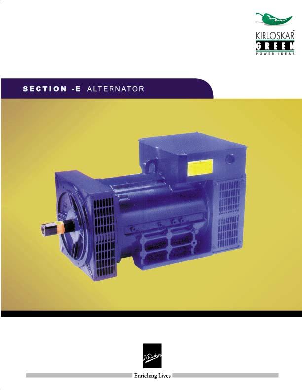
4 KIRLOSKAR GREEN ALTERNATORS Fig. E-1 Fig. E-2 1 End Cover KG BRUSHLESS ALTERNATOR 2 NDE Vent Cover 3 Terminal Board and Rectifier Diode Assly. 4 Terminal Box Cover 5Compound Assembly of Fan and Exciter Rotor-Stator KG BRUSH TYPE ALTERNATOR 1 DE Shield 2 Slotted surround cover 3 Shaft 4 Fan 5Eye bolt 6 Terminal box with LID 7 Excitation (CX) Unit 8 Magnet Frame (Body) NOTE : Depending on which alternator you have in your KGPI genset (please refer our sales office / service dealer) you must refer the illustrations of the same shown above. Only the user serviceable parts are illustrated on the surface of both the alternators above. E-5
5 1.0 GENERAL INFORMATION The Kirloskar Green Alternators are manufactured using the most accurate methods of design, construction and test. Their characteristics, if properly used, ensure a continuous working and a very prolonged trouble free life. For the best use of Kirloskar Green Alternators. Please follow these instructions carefully. 1.1 SPECIFICATIONS : Kirloskar Green Alternators are self excited, self regulated and supplied with Electronic Voltage regulator. They comply with the following International/Indian Standards : ISO : 9001 BS : 5000 IS : 4722 & CSA : Canadian Standard Association (1995) 1.2 MECHANICAL FEATURES Low Weight. Very Compact. Steel Body & C.I. End Shields. Life Lubricated Sealed Ball Bearings at both the ends. Screen Protected: IP 20 (S). Optional: IP 21 (S), IP 23 (S) & IP 44 (S) can be provided. Self Ventilated. Rotating Parts are Dynamically Balanced. 1.3 ELECTRICAL FEATURES Single / Three Phase, 240 Volts / 415 Volts output at 50 Hz. Class F Insulation. Steady State Voltage Regulation of ±5%. Current Compounded Self Excitation System. Lower Harmonic Content of less than 3%, at no load. Power Factor 0.8 Lagging. Phase Sequence is U-V-W when rotated Clockwise viewing from DE side. 1.4 NORMAL OPERATING CONDITIONS (AS PER IS & IS 4722) Altitude Less than 1000 m. Ambient temperature Less than 40 C. Power factor 0.8 Lagging. Speed on load I500 r.p.m. Current Rated current value as mentioned in the nameplate of alternator 1.5 LIMITS FOR SAFE OPERATION : Over speed : 20% (1800 rpm for 50 Hz) Over load : 110% of rated value for one Hr. 2.0 SAFETY REQUIREMENTS : Before any cleaning, lubrication or maintenance operation, ensure that the genset is stationary and disconnected from the power supply. While stopping the gen-set, ensure the compliance with the procedure for stopping prime mover. STOP The alternator, in fact has no emergency stop, but is controlled by the device arranged by the installer to stop the prime mover. Before installing the alternator, arrangements must be made to earth the machine in compliance with any relevant electrical regulations. This is the reason why installer must make sure that the grounding system is in good conditions and in compliance with the regulations of the country where the generators will be installed. CAUTION : THE FINAL INSTALLER IS RESPONSIBLE FOR THE INSTALLATION OF ALL THE PROTECTIONS (SECTIONING DEVICES; PROTECTION AGAINST DIRECT AND INDIRECT CONTACTS, OVER CURRENT AND OVER VOLTAGE P R O T E C T I O N S, EMERGENCY STOP ETC.) NECESSARY FOR THE E-6
6 MACHINE TO COMPLY WITH THE EXISTING INTER- NATIONAL SAFETY REGULATIONS. For handing the unpacked alternators, always use the special eyebolts only, use ropes having a suitable carrying capacity and do not lift the alternator too much from the floor (max. 30 cm.) The operators in charge of the installations, operation and maintenance of the gensets must be skilled technicians who know the characteristics of the gen-sets. The operator must always wear work gloves and safety shoes. In case the alternator or whole DG-SET must be lifted from the floor, the operators must wear a safety helmet. Make sure that the gen-set foundations and base frame are suitable to bear the combined weight of the alternator and prime mover. The alternator should be securely connected and perfectly aligned with the prime mover, otherwise dangerous vibrations may occur resulting in alternator bearing failure. The machine has been designed to ensure the rated output when it is installed in a room having a max. temperature of 40 0 C and at an altitude not exceeding 1000 meters; in case of deviations please make reference to our technical leaflets. No person must wear fluttering cloths (such as scarves etc.) near the machine and any such garment must be fastened with elastic bands at its ends. Alternator must never and for no reason be run with following guards removed : Terminal box cover Rear cover Fan ventilation guard Alternators produce heat proportional to the output. Therefore do not touch it if you do not wear antiscorch gloves, and after switching it off, do not touch it until it has cooled down. Even if all machine components are protected, keep away from the gen-set. Do not lean or sit on the alternator for whatever reason. 2.1 DANGER OF SHORT CIRCUIT The degree of protection of the alternator is IP21. Short circuit may occur if liquids (e.g. water etc.) are split onto areas containing electrical parts. 2.2 STARTING AND STOPPING OPERATIONS: All the instrumentation for starting, running and stopping the system shall be provided by the installer. THE STARTING, RUNNING AND STOPPING OPERATIONS MUST BE CARRIED OUT BY SKILLED PERSONNEL WHO HAVE READ AND UNDERSTOOD THE SAFETY INSTRUCTIONS AT THE BEGINNING OF THIS MANUAL. 2.3 CLEANING : Prior to approaching or touching the alternator, ensure that it is not live and it is at room temperature; at this stage it is possible to clean it on the out side using compressed air. NEVER USE LIQUIDS OR WATER FOR INSIDE CLEANING. E-7
7 N.B. : The alternator frame is provided with many fixing holes so that vibration - damping may be applied in the proper position to ensure the best trim of the genset. 3.0 MECHANICAL COUPLING : ALTERNATOR FOOT FIXING ON THE DE SIDE IS ON END-SHIELD FOOT. HENCE CARE MUST BE TAKEN WHILE CLOSING THE VENT COVER AFTER TIGHTENING THE BOLT THAT NO MATERIAL SHOULD BE LEFT OUT INSIDE, WHICH MAY CAUSE DAMAGE OF FAN UNDER OPERATION. 4.0 ELECTRICAL CHECKS 4.1 CHECKING THE INSULATION RESISTANCE If the alternator has been stored under damp conditions or has taken a lengthy time in shipment, the insulation resistance should be checked. For this purpose, all external connections and neutral to earth link if any should be removed. A Megger of not more than 500 Volts D.C. should be connected between any one AC output terminal and the magnet frame. In case the test reveals the insulation resistance to be less than 2.0 mega ohms (IR value at room temperature), identify the winding or the component by step by step isolation. CAUTION: IF THE INSULATION RESISTANCE IS LESS THAN 2 MEGA OHMS THEN THE ALTERNATOR SHOULD NOT BE OPERATED. 4.2 ELECTRICAL CHECKS : Make sure : A suitable electrical protection device is fitted in the output circuit for safety reasons (in line with the codes of practice in force within the country where the alternator is installed) Ensure before start up that terminal nuts are properly tightened. The control panel protection equipment is correctly set. There is no short circuit due to wrong connections either / or in between the terminals of the alternator and the power switch or breaker (this part of the circuit is not protected by the breaker). 5. SAFETY Basic safety precautions should always be followed to eliminate fire, electric shocks or personal injuries. Always remember safety first. Read and understand all the instructions. Follow alt warnings, safety precautions necessary during the installation, operation & maintenance of the alternator. Cleaning should be done only when the DG set is not running. Do not use damp cloths for cleaning. Do not use any liquid or aerosol cleansers. Use only the eyebolt provided for lifting the alternator. Incorrect lifting or moving may result in equipment damage or personal injuries. Do not overload the cables as it may lead to fires or electric shocks. Never insert any objects inside the alternator as it may lead to fires or electric shocks. Do not spill any liquid on the alternator. Removing the cover of the alternator while it is running will expose you to the dangers of high voltages. Incorrect reassembly can cause electric shocks when the alternator is subsequently used. Ensure that the field pole fasteners are not loose. The earthing for body of alternator and for neutral should always be as specified. 6. DO S and DON T S DO S 1. Tighten the foot mounting bolts. 2. Ensure that the alternator is properly grounded. 3. Ensure the tightness of the terminal bolts. 4. Ensure the crimping of lead wires. 5. Check the fuse if provided. 6. The body and neutral earthing should be perfect. 7. All protection gears should be used as required. 8. The rating of generator should match the load. 9. Ensure that the brushes are fully bedded centrally on the slipring. 10. Check the free movement of the generator shaft by lifting the brushes. 11. Check the spring pressure. 12. Check the voltage during commissioning. 13. Check the phase sequence during installation. 14. All covers and guards should be fitted before starting the generator. E-8

 than the nominal one at rated speed.")
8 15. After servicing the generator, make sure the connections are as per connection diagrams. 16. If the lifting of the alternator is necessary then lift using eye bolts only as shown in the figure. 17. Maintain and operate the generator correctly. 18. Run the DG set daily for at least 5-10 minutes on no load. 7.0 VOLTAGE SETTING AND ROTATING SPEED : The output voltage of the alternator should be checked at rated speed 1500 R.P.M. Usually the alternators are preset at the factory to supply voltage slightly higher (from 3 to 5%) than the nominal one at rated speed. In Frame G2R/160/200/250/280 if one want to regulate the no load voltage of the alternator at determined rated speed it is necessary to operate. 7.1 REMOTE REGULATION OF THE VOLTAGE: (In Frame G2R 160/200/250/280/315) Remote regulation of the voltage is obtained by mounting a 100 KΩ potentiometer between the terminals 5 and 7 permitting a regulation of + 5% of the nominal voltage. WARNING : FOR THE ALTERNATOR GOOD WORKING IT IS ADVISABLE NOT TO DEVIATE FROM THE NOMINAL VOLTAGE MORE THAN 5% Fig. E-3 DON T S 1. Don t operate the machine with higher current than the nameplate current 2. Don t operate the machine at less than 0.8 power factor within deration 3. Don t start the machine with load. 4. Don t operate the generator without the covers. 5. Don t block the air inlet and outlet of the machine. 6. Don t have excessive wiring lengths at the application end. 7. Don t expose the generator to moist condition. 8. Don t use low grade cables. 9. Don t operate the alternator if the IR value is found to be less than 2 mega ohms. 10. Don t apply capacitive loads. 12. Don t run the machine with the field pole fasteners loose. 7.2 ELECTRICAL FAILURE TROUBLESHOOTING When an electrical failure occurs, check for trouble as explained below : 1) In order to find out if the failure has happened in the alternator itself or in the regulation system one has to test the alternator at no load (at nominal speed) exciting the exciter stator directly, using an external dc source. When applying the voltage to the exciter stator one has to comply with polarities : apply the negative polarity of the auxiliary source to the negative terminal and positive terminal to the positive terminal of the exciter fields. Verify that : A) When feeding the winding according to the excitation data at no load (listed in the table) the voltage supplied by the alternator is almost the rated one B) After the localization of fault, repair properly. E-9
9 8. MAINTENANCE 8.1 GENERAL The machine should be completely isolated from all electrically live wires before any electrical or rotating part of it is touched. The frequency of maintenance depends largely on the site conditions. Frequent maintenance of approximate once a week should be practiced at first and the period extended as experience is gained. 8.2 CLEANING The generator and excitation unit should be cleaned internally by blowing out with a jet of dry air and by wiping away any deposits of grease and carbon dust with a clean dry cloth. All fasteners especially the connectors should be inspected for tightness at less frequent intervals. 8.3 BRUSHES (For Brushtype only) The brushes should be closely examined after every 500 hours of operation to establish that they are bedded properly and are not sticking in their holders and that the correct brush pressure is being maintained. Brushes should be replaced with genuine spares before they wear down to 10mm in length. New brushes must be bedded by placing a piece of fine carborundum cloth between the brushes and the slipring with the abrasive side towards the brushes and high application of spring pressure. The cloth should be drawn forward and backward under tension so that it follows the curvature of the slipring. This operation should be finished by several strokes in the direction of rotation, lifting the brushes during the return stroke. It is essential that all carbon and abrasive particles be removed by a jet of dry air and by wiping with a clean and dry cloth. During bedding the adjacent winding should be masked to prevent entry of carbon dust. The pressure on each brush should be checked and adjusted to gms per square cm. Note: Emery paper or any other abrasive should never be used to clean bedded brushes. 8.4 SLIPRINGS (For Brushtype only) Satisfactory electrical operation of the generator depends principally upon maintenance of good working condition of the sliprings. During normal running the rings should have a dark burnished appearance without grooving or uneven wear. During periodic maintenance the sliprings and the grooves between them should be cleaned. If any signs of wear or blackening are observed the spring pressure should be checked and readjusted if required. If blackened badly, the rings should be polished by running the machine and using a fine carborundum or emery paper. This operation is to be carried out with the brushes lifted. If pronounced flats have developed the rings must be skimmed, brushes bedded and the machine cleaned out by blowing compressed air before it is put back in to service. The brush holders should be positioned on the spindle so as to let the brushes ride on the centre of the width of the sliprings. 8.5 BEARINGS WARNING : The field connections Fl & F2 should be removed before working on the sliprings. The bearings used in the machine are from reputed manufacturers and are of sealed type thus requiring no greasing. The bearings are designed for approximately 40,000 hours of use and should be replaced after that. However in case high bearing noise is observed or leakage of grease noticed it is strongly recommended that the bearing be checked and replaced immediately to prevent failure during running as this could cause irreversible damage to the generator. E-10
10 TROUBLE SHOOTING CHART BRUSHLESS ALTERNATORS FAULT CAUSE REPAIR No voltage build - up 1) Insufficient residual voltage 1) Excite the rotor using a battery 2) Improper connection 2) Correct the connection 3) Low speed 3) Reset the speed to the nominal 4) Faulty Winding 4) Check the winding resistance and rewind if required 5) Rotating rectifier failure 5) Replace the rotating rectifier 6) Faulty AVR 6) Replace the AVR Low no - load voltage 1) Low speed 1) Reset the speed to the nominal 2) Faulty Rotating rectifier 2) Replace the rotating rectifier 3) Faulty Winding 3) Check the winding resistance and rewind if required Low voltage on load 1) Low speed at full load 1) Set the rated speed of the prime mover 2) AVR faulty 2) Change AVR 3) Faulty rotor winding 3) Check the rotor winding resistance and if faulty, rewind it 4) Over load on alternator 4) Operate on specified load High voltage on load 1) Capacitors on the load side 1) Disconnect the PF improvement capacitors 2) Faulty AVR setting or 2) Correct the setting / Replace AVR AVR is faulty Too high 1) Excessive speed 1) Adjust the revolving speed no - load voltage 2) Correct the setting Correct the setting Replace AVR Replace AVR Voltage oscillations 1) Incorrect AVR setting 1) Set the AVR stability pot 2) Thyristor load more than 2) Reduce the Thyristor load specified limits 3) Insufficient engine flywheel Unbalance Voltage 1) Unbalance load 1) Correct the load 2) Loose connections 2) Tighten the loose connections 3) Stator winding faulty 3) Check winding resistance & rewind if required E-11
11 TROUBLE SHOOTING CHART BRUSHLESS ALTERNATORS FAULT CAUSE REPAIR Excessive overheating 1) Set misalignment 1) Align the set properly of one or both bearings 2) Bearing loose in end shield 2) Replace the faulty End shield (temp. of bearings over housing 80 0 C) (with or without noise) Excessive overheating 1) Air flow (inlet - outlet) partially 1) Check air inlet - outlets of the of alternator frame clogged or hot air is being alternator circulated either from alternator or prime mover 2) Alternator operating at high 2) Set the voltage to rated value Voltage at load 3) Alternator overloaded 3) Operate at specified load 4) Load PF less than 0.8 lag 4) correct the load power factor Excessive vibrations Defective mounting or play in the Replace the coupling & check the coupling alignment Reset the speed to the nominal Excessive vibration and 1) Three phase alternator is single 1) Check and correct the load humming noise coming phase loaded in excess of from the alternator acceptable limits 2) Start up with no-load : if humming 2) Rewind stator persists - faulty alternator stator winding Smokes, spark or flames Short circuit in the external circuit Stop the set immediately coming from the alternator (including wiring between alternator and control board) Object fallen into the machine short circuit or flash in the stator winding Alternator damaged by Short circuit in external circuit Stop the gen-set immediately a significant impact which Faulty parallel connection (out of phase) is followed by humming Break or deterioration in the coupling and vibration Break or twist in shaft extension Shifting or short circuit of main field winding Bursting or unlocking of the fan Diode burnt, rectifier bridge damaged E-12
12 TROUBLE SHOOTING CHART BRUSHTYPE ALTERNATORS FAULT CAUSE REPAIR No voltage from alternator Open circuit in excitation unit Check the continuity of excitation transformer windings Check rectifier Connections. Wrong field connections Open circuit in field winding Loss of residual magnetism Fault rectifier Faulty surge suppressor unit Defective excitation capacitor Short circuit or open curcuit in armature winding Brushes not bedding properly Check the positive terminal of the rectifier (red wire) connected to F1 and the negative terminal (black wire) to F2. Check the continuity of the field winding, if open connected the joint that have been broken Check the residuaal voltage at the alternator terminals. This should be about 10 volts and balanced between all the three lines. After charging check voltage at the terminals F1 & F2. If there is no D. C. Voltage replace the rectifier (if in doubt) Check the connections. F1 to positive terminal (red) and F2 to negative terminal (black) Check for short circuit or open circuit of the capacitor, if faulty replace it. Armature rewinding is necessary Check if the brushes are sticking in boxes or if bedding is short proper. If the brushes are found tight in the box, just polish the faces of the brush with emery cloth. Check if brush holder leavers are in locked position and the spring pressure is even. E-13
13 TROUBLE SHOOTING CHART BRUSHTYPE ALTERNATORS FAULT CAUSE REPAIR Low or high voltage from Incorrect tappings (shunt) connected Select tappings to get correct voltage alternator on no load if voltage and regulation are not satisfactorily obtained. Incorrect speed of prime mover Unbalanced currents in excitation transformer windings Faulty rectifier Turns shorted in the field coil Check the speed and adjust the speed to 1560 rpm on no load and 1500 rpm on load Reset the excitation unit as per the instructions given. Check the rectifier unit, if current in excitation unit windings are balanced and if the input voltage to the rectifier unit is unbalanced, replace the rectifier. Check the faulty coil and replace it. Voltage regulation is Incorrect speed of the prime mover Adjust the speed of the prime mover unsatisfactory to correct value on no load and full load. The speed should be 1560 rpm on no load. On load the speed should be uniform at 1500 rpm (Full load) Load current are not balanced and within the rated current Open or short circuit in capacitor Series winding of excitation unit are reserved Air gap of excitation unit transformer not correct Machine over loaded Adjust and reduce the load. Check the capacitor and replace if necessary If voltage falls excessively low when load is applied, a possible reason is that the series winding are reversed Check the voltage at the terminals and slipring unit, if there is a large difference reconnect properly If the regulation is marginally outside the limits + 5% then adjustments in air gap to be made. Check the load current with the rated current mentioned on the nameplate. Reduce load if necessary. E-14
14 TROUBLE SHOOTING CHART BRUSHTYPE ALTERNATORS FAULT CAUSE REPAIR Low power factor of the connected load Check power of the load. Power factor equipment is necessary if the power factor is lower than rated p.f. Over heating of alternator Over heating may be generally due to Reduce load so that allowable excessive ambient temperature or altitude temperature are not exceeded Re-circulation of hot air in the vicinity of the alternator Blocking of inlet ventilation louvers Misalignment Overloading of machine Avoid re-circulation by erecting external baffles Clean for free air intake Check the alignment and readjust it Check the load and current with nameplate ratings Over heating of bearing Low speed/frequency incorrect, Correct the speed, assemble reassembly of worn out bearings correctly and replace the bearings Misalignment/Loose coupling bolts Check and correct the misalignment Tighten the coupling bolts Over heating of armature Over loading Adjust load on the alternator Internal short circuit Rewind the armature Over heating of field coils Over heating of alternators Check the load current and reduce the load of capacitors Load power factor low Internal short circuit Improve power factor with connection of capacitor Replace field coils (shorted) High vibrations Loose/Broken Coupling, Loose Tighten or replace the component Foundation Bolts, Damaged Bearings Misalignment Correct the alignment E-15
15 EXPLODED VIEW BRUSHLESS ALTERNATOR G2R/G1R 160/200 Fig. E-4 NOTE : To carry out defective part replacement you may require spares mentioned in the Tables 9.0 and 9.1 as follows. As these parts of an alternator can be seen only after dismantling the alternator (only let trained technicians/ Kirloskar Service Dealer handle it ), we have shown exploded views of the brush type and brushless alternators in figs. E-5 and E-4 respectively. If you still are in need of any of the spare parts mentioned in the list please contact your nearest Kirloskar Service Dealer. E-16
16 9.0 DESIGNATION OF THE SPARE PARTS (Please Refer Fig. C-4) : In case of replacements of spare parts use original spare parts only for the best performance of alternator. For the replacements of worn parts, carefully follow the maintenance instruction, these operations must be carried out by skilled and trained technicians or our authorized service personnel. FRAME : 160 / 200 / 250 / 280 / 315 PART DESCRIPTION NO. PART DESCRIPTION NO. PART NO. DESCRIPTION 3 FRAME WITH WND PACK 4 ROTOR (Wound) 7 WOUND EXCITER STATOR 160 Frame 200 Frame 250/280 Frame 315 Frame 8 WOUND EXCITER ROTOR 160 Frame 200 Frame 250/280 Frame 315 Frame 10a D.E. END SHIELD G1R 160/SAE3 G1R 160/SAE2 G1R 200/SAE3 G1R 250/SAE3 G1R 280/SAE1 G1R 315/SAE1 47 FAN 160 Frame 200 Frame 250 Frame 280 Frame 315 Frame 51 END COVER 160 Frame 200 Frame T. Box ASBY G1R 250 T. Box ASBY G1R 280 T. Box ASBY G1R D.E. VENT COVER G1R 160/SAE 3 G1R 160/SAE 2 G1R 200/SAE 3 G1R 280/SAE 1 G1R 315/SAE 1 54 TERMINAL BOX COVER 160 Frame 200 Frame 55 NDE VENT COVER 160 Frame 200 Frame 65 COUPLING HUB SAE 11.5 FOR G1R160 Frame SAE 11.5 FOR G1R200 Frame SAE 14 FOR G1R250 Frame SAE 14 FOR G1R280 Frame SAE 14 FOR G1R315 Frame 66 COUPLING DISC SET SAE11.5 (Set of 2 Nos.) for G1R 160 SAE11.5 (Set of 3 Nos.) for G1R 200 SAE14 (Set of 4 Nos.) for G1R 280/ N.D.E. BEARING 160 Frame RS 200 Frame RS 250 Frame RS 280 Frame RS 315 Frame RS 325 MAIN TERMINAL BOARD WITH 6 TERMINAL 160 Frame 200 Frame 250 Frame 280 Frame 315 Frame 359 AUXILIARY TERMINAL BOARD (3 TERMINAL) G2R/G1R 160 Frame G2R/G1R 200 Frame 371 DIODE BOARD ASSEMBLY 160/200/250/280 Frames) 315 Frame 386 AVR SR 7/3 AVR UVR - 6 MOV RDN 440/14 for roating Rectifier E-17

17 CONSTRUCTIONAL FEATURES OF THE KIRLOSKAR GREEN BRUSH TYPE ALTERNATORS Fig. E PARTS DESCRIPTION (Please refer Fig. C-5) PART NO. DESCRIPTION QTY. 1 MAGNET FRAME (BODY 1 2 POLE BRICKS 4 3 FIELD COILS 1 SET 4 EYE BOLT 1 5EARTHING SYMBOL PLATE 2 6 ROTOR 1 7 ROTOR COILS 1 SET 8 ROTOR END PLATES 2 9 SHAFT 1 10 FAN KEY 1 11 SLIPRING ASSEMBLY 1 12 BRUSH HOLDER WITH BRUSHES 4 SETS 13 FAN 1 14 EXTENSION KEY 1 NO. E-18
18 PART NO. DESCRIPTION QTY. 15CIRCLIP 1 16 DE BEARING CAP 1 17 DE BEARING 1 18 DE SHIELD 1 19 SLOTTED SURROUND 1 20 BRUSH HOLDER SPINDLE 4 21 NDE BEARING CAP 1 22 NDE BEARING CAP 1 23 NDE SHIELD 1 24 VENTILATION GIRDS 2 25TERMINAL BOX WITH LID 1 26 EXCITATION (CX) UNIT 1 E-19
19 NOTES E-20
 Motor Trouble-Shooting Chart Caution:. Disconnect power to the motor before performing service or maintenance.. Discharge all capacitors before servicing motor.. Always keep hands and clothing away from
R231 A.V.R. Installation and maintenance R 231. This manual is to be given to. the end user. Armature 6- Field. Slow-blow fuse 250V 8 A
 Armature 6- Field This manual is to be given to the end user F1 Slow-blow fuse 250V 8 A 110 0V E+ E- 75 mm 140 mm P1 P2 Voltage Stability R 231 This manual concerns the alternator which you have just purchased.
VOLT POT 1K R220. OPEN FOR 60 Hz STAB A.V.R. R220. Installation and maintenance
 VOLT POT 1K 110 0V E+ E- OPEN FOR 60 Hz STAB This manual concerns the alternator which you have just purchased. We wish to draw your attention to the contents of this maintenance manual. SAFETY MEASURES
DC MOTOR MAINTENANCE ALL ELECTRIC LIFT TRUCKS PART NO SRM 294
 DC MOTOR MAINTENANCE ALL ELECTRIC LIFT TRUCKS PART NO. 897076 620 SRM 294 SAFETY PRECAUTIONS MAINTENANCE AND REPAIR When lifting parts or assemblies, make sure all slings, chains, or cables are correctly
INDUSTRIAL GENERATOR SERVICE
 INDUSTRIAL GENERATOR SERVICE PREVENTATIVE MAINTENANCE PROGRAM Customer: Date: Contact Person: Work Order #: Contact Number: ( ) Technician: INSPECTION COMPONENTS 1. GENERAL Check fuel tank level. Check
MARATHON ELECTRIC INDUCTION GENERATOR
 MARATHON ELECTRIC INDUCTION GENERATOR SINGLE BEARING DESIGN Installation, Operation, and Maintenance Manual Marathon Electric A Subsidiary of Regal-Beloit Corp. 100 East Randolph Street P.O. Box 8003 Wausau,
INDEX Section Page Number Remarks
 INDEX Section Page Number Remarks Synchronous Alternators 2 4 General Fault Finding Capacitors 5 6 Fault Finding & Testing Diodes,Varistors, EMC capacitors & Recifiers 7 10 Fault Finding & Testing Rotors
ELECTRIC HOIST MODEL NO: CH2500B, CH4000B OPERATION & MAINTENANCE INSTRUCTIONS PART NO: , LS1010
 ELECTRIC HOIST MODEL NO: CH2500B, CH4000B PART NO: 7630386, 7630391 OPERATION & MAINTENANCE INSTRUCTIONS LS1010 INTRODUCTION Thank you for purchasing this CLARKE Electric Hoist. Before attempting to use
PANCAKE CAPACITOR GENERATOR Installation, Operation and Maintenance Manual
 PANCAKE CAPACITOR GENERATOR Installation, Operation and Maintenance Manual A Regal Brand TABLE OF CONTENTS INTRODUCTION 2 General Data 2 Initial Inspection 2 SAFETY 2 INSTALLATION 3 Location / Environment
UCDI224E - Technical Data Sheet
 UCDI224E - Technical Data Sheet UCDI224E SPECIFICATIONS & OPTIONS STANDARDS Stamford industrial generators meet the requirements of BS EN 60034 and the relevant section of other international standards
INTRODUCTION GENERAL GUIDELINES ATTACHING THE DRIVE PARTS
 INTRODUCTION Kretzschmar DC motors are of substantialy designed and manufactured to high standards. These motors will work satisfactorily for many years as long as they are maintained following the instructions.
SERVICE SHOP NOTES. Use ohmmeter to check the resistance between the leads.
 SERVICE SHOP NOTES LIMA MAC SELF VOLTAGE REGULATED GENERATORS Troubleshooting Tips Symptom: Engine bogs down or stalls even at no load. Problem: Main stator has one or more taps wound or connected incorrectly.
PI044G - Winding 06 APPROVED DOCUMENT. Technical Data Sheet
 - Winding 06 Technical Data Sheet SPECIFICATIONS & OPTIONS STANDARDS TERMINALS & TERMINAL BOX Stamford industrial generators meet the requirements of BS EN 60034 and the relevant section of other international
UCI274E - Winding 06 APPROVED DOCUMENT. Technical Data Sheet
 - Winding 06 Technical Data Sheet SPECIFICATIONS & OPTIONS STANDARDS Stamford industrial generators meet the requirements of BS EN 60034 and the relevant section of other international standards such as
UCI224E - Winding 06. Technical Data Sheet APPROVED DOCUMENT
 - Winding 06 Technical Data Sheet SPECIFICATIONS & OPTIONS STANDARDS Stamford industrial generators meet the requirements of BS EN 60034 and the relevant section of other international standards such as
R250 A.V.R. Installation and maintenance R250 0V E+ E- VOLT STAB FREQ. & L.A.M. CONFIG. 50Hz. 47.5Hz. 57Hz LAM 1 13% 2 25% OFF LAM OFF 9
 110 0V E+ E- VOLT STAB KNEE 47.5Hz OFF 9 SPECIAL 8 KNEE 65Hz 7 OFF KNEE 6 57Hz OFF 7 8 50Hz o 9 0 5 6 1 2 3 4 OFF 1 13% 2 25% 3 OFF 4 13% 5 25% 60Hz FREQ. & L.A.M. CONFIG. This manual concerns the alternator
PI144J - Winding 05 APPROVED DOCUMENT. Technical Data Sheet
 - Winding 05 Technical Data Sheet SPECIFICATIONS & OPTIONS STANDARDS TERMINALS & TERMINAL BOX Stamford industrial generators meet the requirements of BS EN 60034 and the relevant section of other international
UCI224E - Winding 311 Single Phase. Technical Data Sheet APPROVED DOCUMENT
 - Technical Data Sheet SPECIFICATIONS & OPTIONS STANDARDS WINDINGS & ELECTRICAL PERFORMANCE All generator stators are wound to 2/3 pitch. This Stamford industrial generators meet the requirements of eliminates
UCI224C - Winding 06. Technical Data Sheet APPROVED DOCUMENT
 UCI224C - Winding 06 Technical Data Sheet UCI224C SPECIFICATIONS & OPTIONS STANDARDS Stamford industrial generators meet the requirements of BS EN 60034 and the relevant section of other international
UCI224F - Winding 311 Single Phase. Technical Data Sheet APPROVED DOCUMENT
 - Technical Data Sheet SPECIFICATIONS & OPTIONS STANDARDS WINDINGS & ELECTRICAL PERFORMANCE All generator stators are wound to 2/3 pitch. This Stamford industrial generators meet the requirements of eliminates
SHORT-STOP. Electronic Motor Brake Type G. Instructions and Setup Manual
 Electronic Motor Brake Type G Instructions and Setup Manual Table of Contents Table of Contents Electronic Motor Brake Type G... 1 1. INTRODUCTION... 2 2. DESCRIPTION AND APPLICATIONS... 2 3. SAFETY NOTES...
EDDY CURRENT VARIABLE SPEED DRIVE CONTROLLER - TYPE PM-07
 EDDY CURRENT VARIABLE SPEED DRIVE CONTROLLER - TYPE PM-07 When properly installed, operated and maintained, this equipment will provide a lifetime of optimum operation. It is mandatory that the person
UCI224F - Winding 25. Technical Data Sheet APPROVED DOCUMENT
 - Winding 25 Technical Data Sheet SPECIFICATIONS & OPTIONS STANDARDS Stamford industrial generators meet the requirements of BS EN 60034 and the relevant section of other international standards such as
UCI224F - Winding 14. Technical Data Sheet APPROVED DOCUMENT
 UCI224F - Winding 14 Technical Data Sheet UCI224F SPECIFICATIONS & OPTIONS STANDARDS Stamford industrial generators meet the requirements of BS EN 60034 and the relevant section of other international
UCI224G - Winding 311 APPROVED DOCUMENT. Technical Data Sheet
 - Winding 311 Technical Data Sheet SPECIFICATIONS & OPTIONS STANDARDS WINDINGS & ELECTRICAL PERFORMANCE Stamford industrial generators meet the requirements of BS EN 60034 and the relevant section of other
UCI224E - Winding 311 APPROVED DOCUMENT. Technical Data Sheet
 UCI224E - Winding 311 Technical Data Sheet UCI224E SPECIFICATIONS & OPTIONS STANDARDS WINDINGS & ELECTRICAL PERFORMANCE Stamford industrial generators meet the requirements of BS EN 60034 and the relevant
PI044D - Winding 311 Single Phase APPROVED DOCUMENT. Technical Data Sheet
 - Technical Data Sheet SPECIFICATIONS & OPTIONS STANDARDS Stamford industrial generators meet the requirements of BS EN 60034 and the relevant section of other international standards such as BS5000, VDE
PI144G - Winding 311 Single Phase APPROVED DOCUMENT. Technical Data Sheet
 - Technical Data Sheet SPECIFICATIONS & OPTIONS STANDARDS Stamford industrial generators meet the requirements of BS EN 60034 and the relevant section of other international standards such as BS5000, VDE
PI044H - Winding 311 Single Phase APPROVED DOCUMENT. Technical Data Sheet
 - Technical Data Sheet SPECIFICATIONS & OPTIONS STANDARDS Stamford industrial generators meet the requirements of BS EN 60034 and the relevant section of other international standards such as BS5000, VDE
PI044F - Winding 311 Single Phase APPROVED DOCUMENT. Technical Data Sheet
 - Technical Data Sheet SPECIFICATIONS & OPTIONS STANDARDS Stamford industrial generators meet the requirements of BS EN 60034 and the relevant section of other international standards such as BS5000, VDE
PI044E - Winding 311 Single Phase APPROVED DOCUMENT. Technical Data Sheet
 - Technical Data Sheet SPECIFICATIONS & OPTIONS STANDARDS Stamford industrial generators meet the requirements of BS EN 60034 and the relevant section of other international standards such as BS5000, VDE
PI144E - Winding 311 Single Phase APPROVED DOCUMENT. Technical Data Sheet
 - Technical Data Sheet SPECIFICATIONS & OPTIONS STANDARDS Stamford industrial generators meet the requirements of BS EN 60034 and the relevant section of other international standards such as BS5000, VDE
PI144F - Winding 311 Single Phase APPROVED DOCUMENT. Technical Data Sheet
 - Technical Data Sheet SPECIFICATIONS & OPTIONS STANDARDS Stamford industrial generators meet the requirements of BS EN 60034 and the relevant section of other international standards such as BS5000, VDE
FUJI HEAVY INDUSTRIES LTD.
 RGX6500 RGX7500 FUJI HEAVY INDUSTRIES LTD. 1 2 1. SPECIFICATIONS 3 2. PERFORMANCE CURVES RGX6500 60Hz 240V RGX7500 60Hz 240V 4 3. GENERAL DESCRIPTION Canister?? 5 CONTROL PANEL 50Hz-220V, 240V, 60Hz-220V,
UCI224C - Winding 311 APPROVED DOCUMENT. Technical Data Sheet
 UCI224C - Winding 311 Technical Data Sheet UCI224C SPECIFICATIONS & OPTIONS STANDARDS WINDINGS & ELECTRICAL PERFORMANCE Stamford industrial generators meet the requirements of BS EN 60034 and the relevant
UCI224D - Winding 311 APPROVED DOCUMENT. Technical Data Sheet. Generator Solutions AS
 UCI224D - Winding 311 Technical Data Sheet UCI224D SPECIFICATIONS & OPTIONS STANDARDS WINDINGS & ELECTRICAL PERFORMANCE Stamford industrial generators meet the requirements of BS EN 60034 and the relevant
ALTERNATOR - BOSCH 35/75-AMP & 40/90-AMP
 ALTERNATOR - BOSCH 35/75-AMP & 40/90-AMP 1988 Chrysler LeBaron Convert/Coupe 1988 ALTERNATORS & REGULATORS Chrysler Motors - Bosch 35/75 & 40/90 Amp Alternator All Models DESCRIPTION The charging system
PI044D - Winding 311 APPROVED DOCUMENT. Technical Data Sheet
 PI044D - Winding 311 Technical Data Sheet PI044D SPECIFICATIONS & OPTIONS STANDARDS Stamford industrial generators meet the requirements of BS EN 60034 and the relevant section of other international standards
UCI274E - Winding 14 APPROVED DOCUMENT. Technical Data Sheet
 UCI274E - Winding 14 Technical Data Sheet UCI274E SPECIFICATIONS & OPTIONS STANDARDS Stamford industrial generators meet the requirements of BS EN 60034 and the relevant section of other international
UCI274D - Winding 311 APPROVED DOCUMENT. Technical Data Sheet
 UCI274D - Winding 311 Technical Data Sheet UCI274D SPECIFICATIONS & OPTIONS STANDARDS WINDINGS & ELECTRICAL PERFORMANCE Stamford industrial generators meet the requirements of BS EN 60034 and the relevant
HCI434E/444E - Winding 311 Single Phase APPROVED DOCUMENT. Technical Data Sheet
 HCI434E/444E - Technical Data Sheet HCI434E/444E SPECIFICATIONS & OPTIONS STANDARDS WINDINGS & ELECTRICAL PERFORMANCE All generator stators are wound to 2/3 pitch. This Stamford industrial generators meet
HCI534F/544F - Winding 311 Single Phase APPROVED DOCUMENT. Technical Data Sheet
 HCI34F/44F - Technical Data Sheet HCI34F/44F SPECIFICATIONS & OPTIONS STANDARDS WINDINGS & ELECTRICAL PERFORMANCE All generator stators are wound to 2/3 pitch. This Stamford industrial generators meet
UCDI274J - Winding 311 APPROVED DOCUMENT. Technical Data Sheet
 UCDI274J - Winding 311 Technical Data Sheet UCDI274J SPECIFICATIONS & OPTIONS STANDARDS WINDINGS & ELECTRICAL PERFORMANCE Stamford industrial generators meet the requirements of BS EN 60034 and the relevant
Installation, Maintenance and Operation manual 4 Submersible sand fighter pump. Type: SSFP - Series
 Installation, Maintenance and Operation manual 4 Submersible sand fighter pump Type: SSFP - Series Prakash Pump Warranty We guarantee our products, for the period of 24 months from the date of purchase.
HOT WASHER MODEL NO: KING 125 OPERATION & MAINTENANCE INSTRUCTIONS PART NO: LS1009
 HOT WASHER MODEL NO: KING 125 PART NO: 7320170 OPERATION & MAINTENANCE INSTRUCTIONS LS1009 INTRODUCTION Thank you for purchasing this Hot Washer. This machine is a portable, high pressure power washer,
James Hamilton Electrical Pty Ltd (Inc in Qld) A.C.N trading as. Power Drive Systems. Generator Control Specialists
 A.C.N trading as. Power Drive Systems. Generator Control Specialists") James Hamilton Electrical Pty Ltd (Inc in Qld) A.C.N. 010 848 389 trading as Power Drive Systems Generator Control Specialists 48A Ainsdale Street Telephone: 0500 800 225 P.O. Box 30 West Chermside, Qld
James Hamilton Electrical Pty Ltd (Inc in Qld) A.C.N. 010 848 389 trading as Power Drive Systems Generator Control Specialists 48A Ainsdale Street Telephone: 0500 800 225 P.O. Box 30 West Chermside, Qld
AIR COMPRESSOR OPERATING INSTRUCTION AND PARTS LIST
 AIR COMPRESSOR OPERATING INSTRUCTION AND PARTS LIST BELT TYPE IMPORTANT PLEASE MAKE CERTAIN THAT THE PERSON WHO IS TO USE THIS EQUIPMENT CAREFULLY READS AND UNDERSTANDS THESE INSTRUCTIONS BEFORE STARTING
IMPORTANT INFORMATION
 Table of Contents IMPORTANT INFORMATION Section 1B - Maintenance MAINTENANCE 1 B Specifications........................... 1B-1 Special Tools........................... 1B-2 Mercury/Quicksilver Lubricants
PI144D - Winding 17. Technical Data Sheet APPROVED DOCUMENT
 PI144D - Winding 17 Technical Data Sheet PI144D SPECIFICATIONS & OPTIONS STANDARDS Stamford industrial generators meet the requirements of BS EN 34 and the relevant section of other international standards
HCI434C/444C - Winding 17 APPROVED DOCUMENT. Technical Data Sheet
 - Winding 17 Technical Data Sheet SPECIFICATIONS & OPTIONS STANDARDS TERMINALS & TERMINAL BOX Stamford industrial generators meet the requirements of BS EN 34 and the relevant section of other international
BHARAT ALUMINIUM COMPANY LTD. SPECIFICATIONS FOR SYNCHRONOUS GENERATOR GENERAL Make : Jinan Power Equipment Factory Type : WX2
 BHARAT ALUMINIUM COMPANY LTD. SPECIFICATIONS FOR SYNCHRONOUS GENERATOR 1.00.00 GENERAL 1.01.00 Make : Jinan Power Equipment Factory 1.02.00 Type : WX21Z-073LLT 1.03.00 Reference Standard : GB/T7064-2002
PI144K - Winding 311 APPROVED DOCUMENT. Technical Data Sheet
 PI144K - Winding 311 Technical Data Sheet PI144K SPECIFICATIONS & OPTIONS STANDARDS Stamford industrial generators meet the requirements of BS EN 60034 and the relevant section of other international standards
PI044F - Winding 311 APPROVED DOCUMENT. Technical Data Sheet
 PI044F - Winding 311 Technical Data Sheet PI044F SPECIFICATIONS & OPTIONS STANDARDS Stamford industrial generators meet the requirements of BS EN 60034 and the relevant section of other international standards
PI144J - Winding 311 APPROVED DOCUMENT. Technical Data Sheet
 PI144J - Winding 311 Technical Data Sheet PI144J SPECIFICATIONS & OPTIONS STANDARDS Stamford industrial generators meet the requirements of BS EN 60034 and the relevant section of other international standards
VERTICAL MULTI-STAGE CENTRIFUGAL PUMPS
 Installation and Operating Instructions VERTICAL MULTI-STAGE CENTRIFUGAL PUMPS Models 1, 3, 5, 10, 15, 20, 32, 45, 64, 90 1. Model numbering and nameplate format 1.1 Model numbering Example: SBI / SBN
HCI 534E/544E - Technical Data Sheet
 HCI 34E/44E - Technical Data Sheet SPECIFICATIONS & OPTIONS STANDARDS Newage Stamford industrial generators meet the requirements of BS EN 60034 and the relevant section of other international standards
HCI 434E/444E - Technical Data Sheet
 HCI 434E/444E - Technical Data Sheet SPECIFICATIONS & OPTIONS STANDARDS Newage Stamford industrial generators meet the requirements of BS EN 60034 and the relevant section of other international standards
XR500B Universal Voltage Regulator
 XR500B Universal Voltage Regulator The XR500B is a unique voltage regulator that is designed specifically for Professional Electrical Generator Service and Repair Technicians. The XR500B incorporates patented
A E. P.M.G. range. Low Voltage Alternators - 4 pole. Installation and maintenance
 A E This manual concerns the P.M.G. alternator which which you you have have just just purchased. We wish to draw your attention to the contents of this maintenance manual. SAFETY MEASURES Before using
Medium and high pressure pumps
 Screw pumps Medium and high pressure pumps Installation and Start-up Instruction This instruction is valid for all standard high pressure pumps: E4, D4 and D6 Contents Page Pump identification 2 Installation
MX431 Generator Automatic Voltage Regulator Operation Manual
 Generator Automatic Voltage Regulator Operation Manual Self Excited Automatic Voltage Regulator 1 1. SPECIFICATION Sensing Input Voltage Frequency 190 ~ 264 VAC Max, 1 phase, 2 wire 50 / 60 Hz, selectable
MAKING MODERN LIVING POSSIBLE. Quick Setup VLT FCM 300 Series. Phone: Fax: Web: -
 MAKING MODERN LIVING POSSIBLE Quick Setup VLT FCM 300 Series Factory setting Motors type B14 & B34 mounting Reset (pushbutton) Start Jog Speed reference Fig. 1 - Reset to be closed short time for resetting
HCI 534E/544E - Winding 311 APPROVED DOCUMENT. Technical Data Sheet
 HCI 34E/44E - Winding 311 Technical Data Sheet HCI34E/44E SPECIFICATIONS & OPTIONS STANDARDS TERMINALS & TERMINAL BOX Stamford industrial generators meet the requirements of BS EN 60034 and the relevant
HCI 534C/544C - Winding 311 APPROVED DOCUMENT. Technical Data Sheet
 HCI 34C/44C - Winding 311 Technical Data Sheet HCI34C/44C SPECIFICATIONS & OPTIONS STANDARDS TERMINALS & TERMINAL BOX Stamford industrial generators meet the requirements of BS EN 60034 and the relevant
1 THE WOLVERTON SYSTEM OF TRAIN LIGHTING.
 1 THE WOLVERTON SYSTEM OF TRAIN LIGHTING. The Wolverton equipment is a single battery system utilising a plain shunt wound dynamo. The dynamo is controlled by an automatic field regulator which senses
APPENDIX B SPECIFICATION FOR GENERATOR OVERHAUL EMD MODEL AR10 D18... B-1
 Table of Contents APPENDIX B SPECIFICATION FOR GENERATOR OVERHAUL EMD MODEL AR10 D18... B-1 B.01 SCOPE... B-1 B.02 GENERAL... B-1 B.03 ELECTRICAL QUALIFICATION... B-1 B.04 EQUIPMENT RECONDITIONING... B-2
4291 en /a R220 A.V.R. Installation and maintenance
 4291 en -10.2008 /a Installation and maintenance LEROY-SOMER Installation and maintenance 4291 en-10.2008/a This manual concerns the alternator which you have just purchased. We wish to draw your attention
UCDI224F - Technical Data Sheet
 - Technical Data Sheet SPECIFICATIONS & OPTIONS STANDARDS Newage Stamford industrial generators meet the requirements of BS EN 60034 and the relevant section of other international standards such as BS000,
1100W PORTABLE GENERATOR
 1100W PORTABLE GENERATOR MODEL NO: G1200 PART NO: 8010110 OPERATION & MAINTENANCE INSTRUCTIONS LS0312 INTRODUCTION Thank you for purchasing this CLARKE 1100W Portable Generator. Before attempting to use
PROCESS ELECTRONICS CORPORATION
 MINIVERTER MANUAL PROCESS ELECTRONICS CORPORATION 100 BRICKYARD ROAD MOUNT HOLLY, NORTH CAROLINA 28120 TELEPHONE (800) 421-9107 FAX (704) 827-9595 SALES@PECRECTIFIER.COM WWW.PECRECTIFIER.COM SOLID STATE
UCI224C - Technical Data Sheet
 UCI224C - Technical Data Sheet UCI224C SPECIFICATIONS & OPTIONS STANDARDS Newage Stamford industrial generators meet the requirements of BS EN 60034 and the relevant section of other international standards
UCI274H - Technical Data Sheet
 UCI274H - Technical Data Sheet UCI274H SPECIFICATIONS & OPTIONS STANDARDS Newage Stamford industrial generators meet the requirements of BS EN 60034 and the relevant section of other international standards
UCDI274J - Technical Data Sheet
 UCDI274J - Technical Data Sheet UCDI274J SPECIFICATIONS & OPTIONS STANDARDS Newage Stamford industrial generators meet the requirements of BS EN 60034 and the relevant section of other international standards
ELECTRIC HOIST MODEL NO: CH2500B, CH4000B OPERATION & MAINTENANCE INSTRUCTIONS PART NO: ,
 ELECTRIC HOIST MODEL NO: CH2500B, CH4000B PART NO: 7630386, 7630391 OPERATION & MAINTENANCE INSTRUCTIONS ORIGINAL INSTRUCTIONS LS0517 - Iss 5 INTRODUCTION Thank you for selecting this Clarke Electric Hoist.
HCI634J - Winding 311 and 312 APPROVED DOCUMENT. Technical Data Sheet
 - Winding 311 and 312 Technical Data Sheet SPECIFICATIONS & OPTIONS STANDARDS Stamford industrial generators meet the requirements of BS EN 60034 and the relevant section of other international standards
EA07. Generator Automatic Voltage Regulator Operation Manual
 EA07 Generator Automatic Voltage Regulator Operation Manual Suitable for Single or Three Phase Self Excited Brushless Generator Compatible replacement for Mecc Alte SR-7 * Not a genuine Mecc Alte product.
UCI224F - Technical Data Sheet
 UCI224F - Technical Data Sheet UCI224F SPECIFICATIONS & OPTIONS STANDARDS Newage Stamford industrial generators meet the requirements of BS EN 60034 and the relevant section of other international standards
Service Instructions. Syntron Electromagnetic Feeder Model: F-010-B DF-010-B
 Service Instructions Syntron Electromagnetic Feeder Model: F-010-B DF-010-B Service Manual Syntron Electromagnetic Feeder Models: F-010-B and DF-010-B Installation Operation Maintenance 1 Table of Contents
UCI274D - Technical Data Sheet
 UCI274D - Technical Data Sheet UCI274D SPECIFICATIONS & OPTIONS STANDARDS Newage Stamford industrial generators meet the requirements of BS EN 60034 and the relevant section of other international standards
This manual is to be given to. the end user P.M.G. / ALTERNATORS. Installation and maintenance
 A B C This manual is to be given to the end user Installation and maintenance This manual concerns the PMG which you have just purchased. We wish to draw your attention to the contents of this maintenance
UCI274D - Technical Data Sheet
 - Technical Data Sheet SPECIFICATIONS & OPTIONS STANDARDS Newage Stamford industrial generators meet the requirements of BS EN 60034 and the relevant section of other international standards such as BS000,
UCI274G - Technical Data Sheet
 - Technical Data Sheet SPECIFICATIONS & OPTIONS STANDARDS Newage Stamford industrial generators meet the requirements of BS EN 60034 and the relevant section of other international standards such as BS000,
UCDI274K - Technical Data Sheet
 - Technical Data Sheet SPECIFICATIONS & OPTIONS STANDARDS Newage Stamford industrial generators meet the requirements of BS EN 60034 and the relevant section of other international standards such as BS5000,
INSTALLATION MANUAL. Instructions, precautions, suggestions for installing and servicing resin transformers in full compliance with safety rules
 INSTALLATION MANUAL Instructions, precautions, suggestions for installing and servicing resin transformers in full compliance with safety rules ING TABLE OF CONTENTS 1. General information 2 1.1 Standards
Electric Motor Controls BOMA Pre-Quiz
 Electric Motor Controls BOMA Pre-Quiz Name: 1. How does a U.P.S. (uninterruptable power supply) work? A. AC rectified to DC batteries then inverted to AC B. Batteries generate DC power C. Generator, batteries,
MMA 160S ARC/MMA WELDER OPERATION INSTRUCTIONS
 www.r-techwelding.co.uk MMA 160S ARC/MMA WELDER OPERATION INSTRUCTIONS 2 Thank you for selecting the R-Tech MMA160S Inverter Arc Welder. The MMA160S has many benefits over traditional Arc welders, including
UCDI274K - Technical Data Sheet
 UCDI274K - Technical Data Sheet UCDI274K SPECIFICATIONS & OPTIONS STANDARDS Newage Stamford industrial generators meet the requirements of BS EN 60034 and the relevant section of other international standards
PI144D - Technical Data Sheet
 - Technical Data Sheet SPECIFICATIONS & OPTIONS STANDARDS Stamford industrial generators meet the requirements of BS EN 60034 and the relevant section of other international standards such as BS5000, VDE
PI144J - Technical Data Sheet
 - Technical Data Sheet SPECIFICATIONS & OPTIONS STANDARDS Stamford industrial generators meet the requirements of BS EN 60034 and the relevant section of other international standards such as BS5000, VDE
FAULT FINDING MANUAL. For Stamford AC Generators
 FAULT FINDING MANUAL For Stamford AC Generators 1 SAFETY PRECAUTIONS Test procedures recommended in this manual assume that the reader is fully conversant with electrical safety principles, and is familiar
Manufacturing of: Vehicle Mounted Generators Hydraulic Generators
 Setting the Standard in Mobile Power Instruction Manual for Model HYDRO ARC-S-6500 JSBC Hydraulic Generator Welder Manufacturing of: Vehicle Mounted Generators Hydraulic Generators P.O. Box 582 Chester,
BCI164C - Technical Data Sheet Winding 06
 - Technical Data Sheet Winding 06 SPECIFICATIONS & OPTIONS STANDARDS Newage Stamford industrial generators meet the requirements of BS EN 60034 and the relevant section of other international standards
H.S. MACHINERY RING COMPRESSORS
 OPERATION & PARTS MANUAL Thank you for purchasing an H.S Machinery Limited Regenerative Blower. This product is manufactured under strict ISO-9001-2000 quality control guidelines to ensure your satisfaction.
HCI634V - Technical Data Sheet
 - Technical Data Sheet SPECIFICATIONS & OPTIONS STANDARDS Newage Stamford industrial generators meet the requirements of BS EN 60034 and the relevant section of other international standards such as BS5000,
VERTICAL MULTI-STAGES CENTRIFUGAL PUMPS
 Installation and Operating Instructions VERTICAL MULTI-STAGES CENTRIFUGAL PUMPS Models 1, 3, 5, 10, 15, 20, 32, 45, 64, 90, 120, 150 1. Model numbering and nameplate format 1.1 Model numbering Example:
SERIES PC INSTRUCTION AND OPERATION MANUAL
 MEGGA SERIES PC INSTRUCTION AND OPERATION MANUAL Models PCT and PCF Close-coupled and frame-mounted single-stage horizontal end-suction pumps. WARNING: Read this manual before installing or operating this
HCI 534C/544C - Technical Data Sheet
 HCI 34C/44C - Technical Data Sheet HCI34C/44C SPECIFICATIONS & OPTIONS STANDARDS Newage Stamford industrial generators meet the requirements of BS EN 60034 and the relevant section of other international
HCI634H - Winding 311 and 312. Technical Data Sheet
 HCI634H - Winding 311 and 312 Technical Data Sheet HCI634H SPECIFICATIONS & OPTIONS STANDARDS Stamford industrial generators meet the requirements of BS EN 60034 and the relevant section of other international
UCI274H - Technical Data Sheet Winding 06
 - Technical Data Sheet Winding 06 SPECIFICATIONS & OPTIONS STANDARDS Newage Stamford industrial generators meet the requirements of BS EN 60034 and the relevant section of other international standards
THREE PHASE AND SINGLE PHASE ASYNCHRONOUS ELECTRIC MOTORS OPERATION AND MAINTENANCE BOOKLET Rev
 MORATTO S.R.L. Electrical Machinery I 31030 PERO DI BREDA (Treviso) Italy Via A Volta, 2 Tel. +390422904032 fax +39042290363 www. moratto.it - moratto@moratto.it THREE PHASE AND SINGLE PHASE ASYNCHRONOUS