Burners. Self-recuperative burners high speed free flame REKO-SIK-FF (E3901FF rev /05/2009)
|
|
|
- Kristin Gardner
- 5 years ago
- Views:
Transcription


1 Burners Self-recuperative burners high speed free flame REKO-SIK-FF (E3901FF rev /05/2009)
2 GENERAL WARNINGS: DISPOSAL: ¾ All installation, maintenance, ignition and setting must be performed by qualified staff, respecting the norms present at the time and place of the installation. ¾ To avoid damage to people and things, it is essential to observe all the points indicated in this handbook. The reported indications do not exonerate the Client/User from observing general or specific laws concerning accidents and environmental safeguarding. ¾ The operator must wear proper DPI clothing (shoes, helmets...) and respect the general safety, prevention and precaution norms. ¾ To avoid the risks of burns or high voltage electrocution, the operator must avoid all contact with the burner and its control devices during the ignition phase and while it is running at high temperatures. ¾ All ordinary and extraordinary maintenance must be performed when the system is stopped. To dispose of the product, abide by the local legislations regarding it. GENERAL NOTES: ¾ In accordance to the internal policy of constant quality improvement, ESA-PYRONICS reserves the right to modify the technical characteristics of the present document at any time and without warning. ¾ It is possible to download technical sheets which have been updated to the latest revision from the website. CERTIFICATIONS: ¾ To assure correct and safe use of the combustion plant, it is of extreme importance that the contents of this document be brought to the attention of and be meticulously observed by all personnel in charge of controlling and working the devices. ¾ The functioning of a combustion plant can be dangerous and cause injuries to persons or damage to equipment. Every burner must be provided with certified combustion safety and supervision devices. ¾ The burner must be installed correctly to prevent any type of accidental/undesired heat transmission from the flame to the operator or the equipment. EN746-2 The products manufactured by ESA-PYRONICS have been created in conformity to the UNI EN 746-2:2010 Norms: Equipment for industrial thermal process - Part 2: Safety requirements for combustion and the movement and treatment of combustible elements. This norm is in harmony with the Machine Directive 2006/42/CE. It is certified that the products in question respect all the requirements prescribed by the above mentioned Norms and Directives. These have been designed, produced, controlled and tested in accordance to the company s internal procedures for quality control, certified in conformity with the UNI EN ISO 9001:2008 Norm by DNV Italia s.r.l. The products conform to the Russian market requirements according to the GOST and GOSGORTEKHNADZOR certification. ¾ The performances indicated in this technical document regarding the range of products are a result of experimental tests carried out at ESA-PYRONICS. The tests have been performed using ignition systems, flame detectors and supervisors developed by ESA-PYRO- NICS. The respect of the above mentioned functioning conditions cannot be guaranteed if equipment, which is not present in the ESA-PYRONICS catalogue, is used. Headquarters: Esa S.p.A. Via Enrico Fermi Curno (BG) - Italy Tel Fax esa@esacombustion.it CONTACTS / SERVICE: International Sales: Pyronics International s.a. Zoning Industriel, 4ème rue B-6040 Jumet - Belgium Tel Fax marketing@pyronics.be 2


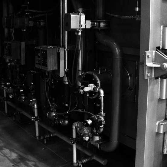
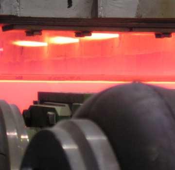
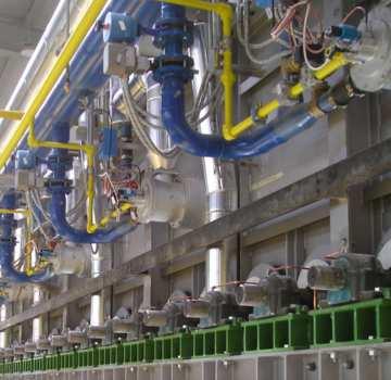
3 REKO-SIK-FF are self - recuperative gas burners for direct heating. These burners use combustive fumes to preheat the combustive air. Depending on size and conditions of use, this type of burner guarantees a substantial reduction in consumption compared to traditional burners. APPLICATIONS ¾Furnaces with fibre covering. ¾Ceramic or treatment furnaces. ¾Tunnel or chariot furnaces. ¾Furnaces with continuous or discontinuous function. ¾Furnaces with pulse-firing burner control. F3901FF03 CHARACTERISTICS GENERAL: ¾Capacity: from 30 to 240 kw ¾Functions with various types of gas: CH4/LPG/Propane/etc. ¾Maximum furnace temperature: 1300 C ¾Burner inlet air pressure: 70 mbar ¾Burner inlet gas pressure: 70 mbar ¾Inlet air temperature: environment ¾Preheated air temperature: up to 750 C ¾Potential ratio: 1:5 ¾Flame velocity: up to 140 m/s ¾Low NOx e CO emission ¾Highly efficient ejector to evacuate 100% of the fumes emitted during combustion. MATERIAL COMPOSITION: ¾Exhaust air-inlet body: ¾Gas collector pipe: ¾Exchange tube: ¾Combustion head: ¾Exhaust guiding spacer: ¾Surface treatment: AISI304 Cast Iron G25 AD-SIC INCOLOY601/AISI310S AISI304/FL35 galvanization, steel pickling, high temperature painting F3901FF04 3
4 CAPACITY AND FLAME LENGTH PARAMETERS The REKO-SIK-FF ignition takes place through a high tension discharge, which is carried out by a WAND electrode. The flame is detected via a uv-scanner (not included). The adoption of flame controls is highly recoended in all systems operating at temperatures below 750 C (UNI EN746-2 Norm). Model Capacity kw Flame length Flame velocity (m/s) Ignition Detection REKO-1-SIK-FF WAND UV-2 REKO-2-SIK-FF WAND UV-2 REKO-3-SIK-FF WAND UV-2 REKO-4-SIK-FF WAND UV-2 REKO-5-SIK-FF WAND UV-2 DESCRIPTION The REKO-SIK-FF burners use the temperature exhaust fumes to preheat the combustive air, thus saving more energy and reducing atmospheric pollution. FLUE GAS OUTLET T AIR UP TO 750 C FLUE GAS RECIRCULATION COMBUSTION AIR INLET COMBUSTION GAS PREHEATED AIR FLUE GAS EJECTOR AIR INLET GAS INLET D3901FF01 The choice of materials has been made according to the burners performance. Furthermore, the stainless steel exhaust-air inlet body, assures a high resistance to heat and oxidation. The heat exchanger element is made of silicon carbide and its special conformation allows the optimization of heat transfer from the combustion products to the combustive air. This choice allows the burner to be used with maximum chamber temperature of up to 1300 C under direct heating conditions. 4
5 Multistage combustion technology, together with the recycling of combustive gases, guarantees low NOx and CO emissions, despite the preheating air temperature value of up to 750 C. The REKO-SIK-FF are compact burners with reduced weight and size. They have separate gas and air inlets, nozzle mixers (no flashbacks) and include: The flame capacity, length and velocity concern natural gas burners (8600 Kcal/Nm 3 ), placed in a combumicrometric gas adjuster, spark electrode, peep sight, gas calibrated orifice flow meter, furnace wall spacer and flue gas ejector. The suggested functioning is with MIN/MAX or ON/OFF and the setting is simplified by special pressure inlets on the air and gas side. BURNER PERFORMANCES stion chamber with zero pressure and at sea level, which can function with 10% of excess air. ¾MIN/MAX (ON/OFF) functioning ¾Chamber temperature 1100 C ¾NOx < 350 mg/nm 3 [O 2 = 3% ref.] MAXIMUM CAPACITY Maximum power Free flame application Burner model REKO-1-SIK REKO-2-SIK REKO-3-SIK REKO-4-SIK REKO-5-SIK SiC recuperator length [] Burner capacity (2% O 2 ) [kw] Burner air flow [Nm 3 /h] Ejector air flow [Nm 3 /h] Total air flow (burner air + ejector air) [Nm 3 /h] Gas flow [Nm 3 /h] Burner air inlet pressure [mbar] Ejector air inlet pressure [mbar] p flange gas measurement [mbar] MINIMUM CAPACITY Minimum power Free flame application Burner model REKO-1-SIK REKO-2-SIK REKO-3-SIK REKO-4-SIK REKO-5-SIK Burner capacity (2% O 2 ) [kw] Burner air flow [Nm 3 /h] Ejector air flow [Nm 3 /h] Total air flow (burner air + ejector air) [Nm 3 /h] Gas flow [Nm 3 /h] Burner air inlet pressure [mbar] Ejector air inlet pressure [mbar] p flange gas measurement [mbar]
6 EFFICIENCY TABLES Permanent operation (100% Fire) 1200 REKO-1-SIK-FF REKO-2-SIK-FF Furnace Temperature [ C] REKO-3-SIK-FF REKO-4-SIK-FF REKO-5-SIK-FF ,0 70,0 75,0 80,0 85,0 Efficency [%] G3901FF01 Permanent operation (100% Fire) 1200 REKO-1-SIK-FF REKO-2-SIK-FF REKO-3-SIK-FF REKO-4-SIK-FF Furnace Temperature [ C] REKO-5-SIK-FF Flue Gas Temperature [ C] G3901FF02 6
7 EFFICIENCY TABLES Permanent operation (100% Fire) 1200 REKO-1-SIK-FF REKO-2-SIK-FF Furnace Temperature [ C] REKO-3-SIK-FF REKO-4-SIK-FF REKO-5-SIK-FF Preheated air [ C] G3901FF03 7
8 FLOW SCHEME - FREE FLAME BURNER D3901FF02 Pos. Description Included Not Included 1 Gas ball valve x 2 Gas calibrated flange x 3 Pressure regulator x 4 Safety solenoid valve x 5 Throttle valve x 6 Ignition electrode x 7 Flame control x 8 Air ball valve x 9 Uv-scanner for flame detection x 10 Regulation valve x 11 Combustion air orifice flow meter x 12 Combustion air gate valve x 13 Ejector air gate valve x 14 Self-recuperative burner x 15 Furnace wall adapting spacer x 8
9 WARNINGS ¾ The REKO-SIK-FF burner series is intended for fixed installations. If mobile installations are needed (bell furnaces, etc...) it is necessary to preventively take into consideration the possibility of damage to hoses in silicon carbide, which is determined by the movement of the actual furnace. ¾ The burner must always be turned on at minimum power, then modulating towards the maximum, facilitating ignition and reducing exit overpressure. ¾ The passing from minimum power to maximum power must always be done gradually and not instantaneously. To do this, the use of two-phase MRBV air regulation valves is suggested. ¾ For all applications at low temperature (up to 750 C), burner ignition and the control of solenoid gas valves must be accomplished using a certified burner control device. ¾ To avoid possible damage to the burners, make sure that the blower does not send them hot or foul air (from combustion products, oils, solvents or other). To avoid this from occurring, install the blower or the air suction duct outside the establishment and far from the exhaust pipes. ¾ Check that the power lines are properly connected after the installation. Check the correct air and gas pressures (pag. 5). ¾ The burner can only work within the indicated power ranges. The functioning with less or more power can compromise the correct functioning and life span of the actual burner. In this case the general warrantee conditions will not be applicable anymore and ESA-PYRO- NICS will not be held responsible for any damage caused to persons or things. ¾ If there is trouble with other devices during the burner start up phase, use the connector with anti disturbance filter for the high-tension (HT) cable connection of the ignition electrode. ¾ Avoid burner ignition close to each other so as not to heat the ignition coand system devices (solenoid valves and transformers). Prewash time lapse + first safety time lapse + min. of 5 sec. = time lapse between one ignition and another. (however, do not attempt more than 2 ignitions during a 30sec. time lapse). ¾ Make sure the power supply is TURNED OFF when intervening on the burner and its devices. In case of burner malfunctioning, follow the indications in the Maintenance chapter of the present manual or contact ESA-PYRONICS assistance. ¾ Any modification or repair done by third parties can compromise the application safety and automatically cause the general warrantee conditions to expire. 9
10 INSTALLATION The REKO-SIK-FF burners are provided with a special furnace wall adapting spacer. The light obtained from the lodging of the burner and its spacer must provide free space around the burner, which has to subsequently be packed with refractory material such as ceramic fibre (see pag.16) Cautiously follow the indications below for the installation: 1 - Place REKO burners far from heat sources and products like: liquids, solvents or corrosive gases. 2 - Make sure the dimensions of the lodging and distance between the stoking pipes and the exhaust pipes correspond to those specified in the Overall Dimensions chapter pag Assemble the spacer on the walls of the furnace (pos. 01) interposing ceramic fibre gaskets between the flanges (pos. 02). During this phase make sure that the external insulation wrapping does not get altered or damaged. Once the spacer is fitted to the wall, from the inside of the combustion chamber, seal all possible cracks that are left between the wall and the spacer with refractory ceramic material. 4 - Insert the burner (pos. 03) into the spacer, interposing ceramic fibre gaskets (pos. 04), making sure that the correct positioning of the air and gas inlets as well as the exhaust pipe have been checked. During this procedure it is necessary to pay close attention to avoid rupturing or damage of the silicon carbide flame tube (pos. 05). 5 - Fit the ejector/chimney assembly at the exhaust outlet (pos. 06). The use of open natural draught hoods is advised so as to avoid exhaust fume pressure, which in turn can create conditions of stress and malfunctioning for the burner. 6 - Assemble the pre-installation of the combustion air lines and ejector (pos. 07) through the rubber compensators (pos. 10) that must then be shut via the appropriate collars. 7 - Connect the burner air and gas inlet tubes, interposing, if possible, dilation joints in AISI. 8 - To the uv-detecting spacer (pos. 08),on the predisposed inlet for the cooling process, connect a hose of Ø 8 with relative fitting. This must carry fixed air for the cooling process of the sensor. 9 - Connect electricity to the ignition electrode and to the uv-scan detector making sure not to pass the conductors near heat sources Check to see that the burner body and all its metallic elements are earthed with appropriate conductors The connecting cable from the ignition transformer to the electrode must be specific for high tension and not screened. It must not be more than 1 meter long; otherwise the ignition transformer must be positioned near the burner. The high tension cable must be placed far from the power cables and not in metallic ducts. Ideally it should be left in open air FLUE GAS OUTLET LEFT SIDE VERSION AIR INLET RIGHT SIDE VERSION AIR INLET D3901FF03 FLUE GAS OUTLET NB: gas insertion may be supplied on request. D3901FF04 For more information refer to the technical sheet concerning ignition transformers. 10
11 START UP AND SETTING The procedures indicated in the following chapter must be carried out by expert technicians. The non-observance of the instructions given can provoke dangerous conditions. 1 - Check that the combustion air pressure exiting the blower and the combustive fuel pressure are both within the allowed range. 2 - Adjust the working pressure and the safety device pressure of the combustion plant, whether there is one per burner or one for the whole plant i.e. gas pressure reduction gear, block valve, relief valve, pressure switches etc. Simulate the intervention of all the safety devices including the intervention of the safety over temperature, checking that the fuel safety block devices act properly. 3 - Place the air regulation valve in the maximum opening position and adjust the burner and ejector inlet air pressure, via the gate valve. This must be done referring to the values indicated in the Burner Performances chapter for the maximum power pag Place the air regulation valve in the minimum opening position and adjust its opening to obtain (in burner and ejector inlet) the relative minimum power pressure. 5 - Activate the burner control device and attempt the ignition until the burner switches on. While attempting to ignite the burner, act on the gas adjustment valve and, starting from the totally closed position, open it gradually until the burner ignites. 6 - Fully open the air regulation valve and adjust, via the gas adjustment valve, the maximum fuel capacity, checking the differential pressure created on the calibrated gas flange. 7 - Double check that, at minimum and maximum power, the burner and ejector inlet pressures correspond to the values in the in the Burner Performances chapter. These values may be different depending on whether the burner is on or off. 8 - If necessary, with all burners turned onto the same power, analyze the combustion products in the chamber (where possible) or exiting each burner (on the exhaust muff). 9 - Repeatedly attempt ignition at minimum burner power, with maximum amplitude, to check the ignition reliability and flame stability during the adjustment. 11
12 NATURAL GAS CAPACITY TABLE - REKO-SIK-FF 10 REKO-1-SIK REKO-2-SIK REKO-3-SIK REKO-4-SIK REKO-5-SIK AIR CAPACITY TABLE - REKO-SIK-FF 100 REKO-1-SIK Differential pressure at orifice flow meter [mbar] 1 0, Natural gas 20 C P.S.=0,6 (Nm 3 /h) G3901FF04 REKO-2-SIK REKO-3-SIK REKO-4-SIK REKO-5-SIK Burner feeding pressure [mbar] Total air flow (burner + 30 C P.S.= 1 [Nm3/h] G3901FF
13 GENERAL MAINTENANCE PLAN Operation Type Advised time Notes High tension electrode connection O annual check integrity of outer plastic and oxidization of internal electrode terminal Electrode ignition O annual replace if the kantal terminal is worn Flexible rubber joints in air line S every semester Fume guiding tube spacer integrity S annual SiC heat exchanger integrity S annual Cleaning of uv-scanner watch glass O every semester Uv-scanner replacement O h of functioning check that there are no leaks nor vulcanized rubber at every maintenance check with furnace turned off, from the inside, make sure there are no cracks in the refractory material at every maintenance check with furnace turned off, from the inside, make sure there are no cracks in the refractory material reduce to a quarterly check in dusty environments. in any case every 2 years Replacement of ejector gaskets (*) S annual to be done only when the furnace is off and cold. Replacement of gas side gaskets (**) S annual see note Burner setting O annual repeat the steps in the IGNITION AND SET- TING section on page 11 NOTES: Caption: O = ordinary / S = extraordinary (*) it is suggested that the gaskets on the gas side are replaced after every disassembly of the gas feeding line. (**) use high temperature gaskets 13
14 ORDINARY MAINTENANCE For correct dismantling and better maintenance of the REKO-SIK-FF burners, meticulously follow the instructions below with the plant turned off. CLEANING OF UV-SCANNER WATCH GLASS 1 - Check that the burner control device is not connected. 2 - Disconnect power supply to the uv-scanner (pos. 01) and the cooling line (where present pos. 07). 3 - Unscrew the aluminium pipe fitting (pos. 06) at the base of the gas collector, removing the uv-scanner with its spacer. 4 - Unscrew the aluminium fitting from the insulation teflon connector (pos. 03) and remove the quartz watch glass (pos. 05). 5 - Clean the quartz watch glass with a damp cloth and proceed to reassemble everything making sure that both the glass as well as the gaskets are put back in the correct positions (pos. 04) between the aluminium teflon spacer, before tightening. 6 - Restore the cooling hoses and power connection. 7 - Check the correct flame detection of the uv-scanner G3901FF
15 EXTRAORDINARY MAINTENANCE For correct dismantling and better maintenance of the REKO-SIK -FF burner, meticulously follow the instructions below with the plant turned off. BURNER SHUTDOWN In shutdown conditions of the burner refer to the burner control device indications and to the relative manual to identify the cause. The main cases are indicated here below: ¾Illegal flame detection: the shutdown is due to an illegal flame detection during the phases prior to ignition or after the turning off. The causes are within the detection system (broken or faulty sensor or presence of humidity), or in the gas draw from the electric safety valve, which allows the burner to remain turned on. ¾Failed ignition: shutdown is caused by the fact that no flame has been created during the staring process. The causes can be found in the start up system (spark absence, faulty electrodes or incorrect position), in the bad setting of the fuel and combustion flow or in the detection system (faulty sensor or interrupted cables). More precisely, in the first two cases the flame is not ignited, while in the last case the flame is created but the burner control device is unable to detect it. ¾Flame signal loss: shutdown due to the loss of flame signal during the normal functioning of the burner. The causes can be found in the combustion air flow adjustment (rapid flow variations, adjustment out of allowed range). They can also be found in the detection system (faulty, dirty or badly positioned sensors). UV-SCANNER REPLACEMENT 1 - Check that the burner control device is not connected. 2 - Disconnect the electrical flow to the uv-scanner (pos. 01) and to the cooling line (where present). 3 - Unscrew the aluminium pipe fitting at the base of the gas collector (pos. 02), removing the uv-scanner with its spacer. 4 - Screw the new component back on, in the same position, after having checked the correct position of the watch glass insulation between the aluminium and teflon spacers. 5 - Restore the cooling pipes and the electrical connection. 6 - Check the correct uv-scanner flame detection. IGNITION ELECTRODE REPLACEMENT Check that the burner control device is not connected. 2 - Disconnect the Ht cable, by disconnecting the electrode insulation connector (pos. 06). 3 - Unscrew the upper connector (pos. 03) and then extract the retaining spring (pos. 04) and the electrode (pos. 05). 4 - Insert the new electrode, checking its beat. Place the retaining spring back inside and completely screw the connector back on again. 5 - Reconnect the electrode insulation connector. Replace it if necessary D3901FF
16 OVERALL DIMENSIONS - REKO-SIK-FF Ø"M" "N"±5 FLUE GAS TUBE SUGGESTED CONFIGURATIONS MIN. Ø"R" MIN. Ø"R" BY CUSTOMER "K" Nr."W" holes Ø"Y" eq.sp. on Ø"Z" D.B.C. Ceramic fiber insulation "I" "L" Ø"Q" FURNACE WALL HOLE Ø"H" 70±5 GAS INLET Ø"B" "G" ORIFICE FLOWMETER (INCLUDED) "F" MIN 100 BY CUSTOMER NOTES: (a) Gas line, flue gas & ejector line adjustable according to customer requests. WALL THICKNESS "X" "P" "P"-"X" "C" "D" AIR INLET Ø"A" MIN 100 BY CUSTOMER Ø"B" "E" D3901FF07 Burner Model A B C D E F G H K I L M N W Y Z P Q R (*) Mass Kg (**) REKO-1-SIK Rp 1.1/2 Rp 1/ ø REKO-2-SIK Rp 2.1/2 Rp 1/ ø 2.1/ / REKO-3-SIK Rp 3 Rp 3/ ø REKO-4-SIK DN100 Rp ø REKO-5-SIK DN100 Rp ø Important note: X wall thickness is the responsibility of the Client. (*) Approximate diameter (depends on the exhaust pipe conformation). (**) Burner mass including air lines, ejector and furnace wall spacer. 16
17 ORDERING INITIALS - COMPLETE BURNER REKO - - SIK - - FF Model Version REKO-1-SIK REKO-2-SIK REKO-3-SIK... (ref. capacity table) Right Left R L Gas adjuster Wall thickness With gas adjuster Without gas adjuster GA* F Indicate length in (see size diagrams)... Fuel Flanging type Natural gas LPG Poor gas ( 1 ) CH4 GPL GP As ESA drawing As customer drawing E* C The initials marked with an asterisk (*) identify the standards. Notes: 1 Particular performance according to gas characteristics To check the components that are not supplied with the burner, consult the burner flow scheme on page
18 ESA worldwide distribution AUTHORIZED DISTRIBUTION STAMP If you have any doubt about the qualifi cation or identity of the distributor, please check that they appear on our website in the Sales Contacts section, or contact us directly at 2012 ESA S.p.A. Company under the management and coordination of SIAD S.p.A. All rights reserved. The information contained herein is offered for use by technically qualifi ed personnel at their discretion and risk without warranty of any kind. We regularly update our data, for updated data please visit our web site Printed in Italy CATukR00/12 Head Office and Factory ESA S.p.A. Company under the management and coordination of SIAD S.p.A. Via E. Fermi, 40 I Curno (Bergamo) ITALY Tel Fax Share Capital euro ,00 paid up - Fiscal Nr.: V.A.T. Nr.: (IT) Reg. Impr. Bg Nr.: R.E.A. BG Export: BG Pyronics International s.a. Zoning Industriel, 4ème rue B-6040 Jumet BELGIUM marketing@pyronics.be Tel Fax
Burners. Self-recuperative burners high speed with flat flame REKO-SIK-SW (E3903 rev /06/2015)
") Burners Self-recuperative burners high speed with flat flame REKO-SIK-SW (E3903 rev. 01-08/06/2015) GENERAL WARNINGS: DISPOSAL: ¾ All installation, maintenance, ignition and setting must be performed by
Burners Self-recuperative burners high speed with flat flame REKO-SIK-SW (E3903 rev. 01-08/06/2015) GENERAL WARNINGS: DISPOSAL: ¾ All installation, maintenance, ignition and setting must be performed by
Burners. Pilot Heads BTC & BTSA (E3121 rev /09/2010)
") Burners Pilot Heads BTC & BTSA (E3121 rev. 01-06/09/2010) GENERAL WARNINGS: DISPOSAL: ¾ All installation, maintenance, ignition and setting must be performed by qualified staff, respecting the norms present
Burners Pilot Heads BTC & BTSA (E3121 rev. 01-06/09/2010) GENERAL WARNINGS: DISPOSAL: ¾ All installation, maintenance, ignition and setting must be performed by qualified staff, respecting the norms present
Orifice Flow Meters POP-S (E5720 rev /03/2013)
") Accessories Orifice Flow Meters POP-S (E5720 rev. 05-20/03/2013) GENERAL WARNINGS: DISPOSAL: ¾ All installation, maintenance, ignition and setting must be performed by qualified staff, respecting the norms
Accessories Orifice Flow Meters POP-S (E5720 rev. 05-20/03/2013) GENERAL WARNINGS: DISPOSAL: ¾ All installation, maintenance, ignition and setting must be performed by qualified staff, respecting the norms
Burners. Metallic free flame burners. EMB (E3004 rev /02/2010)
") Burners Metallic free flame burners EMB (E3004 rev. 06-11/02/2010) GENERAL WARNINGS: DISPOSAL: ¾ All installation, maintenance, ignition and setting must be performed by qualified staff, respecting the
Burners Metallic free flame burners EMB (E3004 rev. 06-11/02/2010) GENERAL WARNINGS: DISPOSAL: ¾ All installation, maintenance, ignition and setting must be performed by qualified staff, respecting the
Burners. Pilot Heads BTC & BTSA (E3121 rev /04/2018)
") Burners Pilot Heads BTC & BTSA (E3121 rev. 02-24/04/2018) GENERAL WARNINGS: DISPOSAL: ¾ All installation, maintenance, ignition and setting must be performed by qualified staff, respecting the norms present
Burners Pilot Heads BTC & BTSA (E3121 rev. 02-24/04/2018) GENERAL WARNINGS: DISPOSAL: ¾ All installation, maintenance, ignition and setting must be performed by qualified staff, respecting the norms present
Free flame burners EMB (E3004 rev /02/2015)
") Burners Free flame burners EMB (E3004 rev. 08-10/02/2015) GENERAL WARNINGS: DISPOSAL: ¾ All installation, maintenance, ignition and setting must be performed by qualified staff, respecting the norms present
Burners Free flame burners EMB (E3004 rev. 08-10/02/2015) GENERAL WARNINGS: DISPOSAL: ¾ All installation, maintenance, ignition and setting must be performed by qualified staff, respecting the norms present
Burners. High velocity LOW NOx combustion air burners EMB-SIK-NxT (E3507 rev /11/2016)
") Burners High velocity LOW NOx combustion air burners EMB-SIK-NxT (E3507 rev. 05-28/11/2016) GENERAL WARNINGS: GENERAL NOTES: ¾ All installation, maintenance, ignition and setting must be performed by qualified
Burners High velocity LOW NOx combustion air burners EMB-SIK-NxT (E3507 rev. 05-28/11/2016) GENERAL WARNINGS: GENERAL NOTES: ¾ All installation, maintenance, ignition and setting must be performed by qualified
Valves. Slow opening and rapid closing solenoid valves VM-L (E1111 rev /11/2012)
") Valves Slow opening and rapid closing solenoid valves VM-L (E1111 rev. 03-19/11/2012) GENERAL WARNINGS: DISPOSAL: ¾ All installation, maintenance, ignition and setting must be performed by qualified staff,
Valves Slow opening and rapid closing solenoid valves VM-L (E1111 rev. 03-19/11/2012) GENERAL WARNINGS: DISPOSAL: ¾ All installation, maintenance, ignition and setting must be performed by qualified staff,
Valves. Rapid opening and closing solenoid valves VMR (E1110 rev /11/2012)
") Valves Rapid opening and closing solenoid valves VMR (E1110 rev. 03-19/11/2012) GENERAL WARNINGS: DISPOSAL: ¾ All installation, maintenance, ignition and setting must be performed by qualified staff, respecting
Valves Rapid opening and closing solenoid valves VMR (E1110 rev. 03-19/11/2012) GENERAL WARNINGS: DISPOSAL: ¾ All installation, maintenance, ignition and setting must be performed by qualified staff, respecting
Radiant tube burners RT (E3900 rev /01/2018)
") Burners Radiant tube burners RT (E3900 rev. 09-23/01/2018) GENERAL WARNINGS: DISPOSAL: ¾ All installation, maintenance, ignition and setting must be performed by qualified staff, respecting the norms present
Burners Radiant tube burners RT (E3900 rev. 09-23/01/2018) GENERAL WARNINGS: DISPOSAL: ¾ All installation, maintenance, ignition and setting must be performed by qualified staff, respecting the norms present
Burners. Ribbon linear flame burners AB & ABM (E3010 rev /11/2017)
") Burners Ribbon linear flame burners AB & ABM (E3010 rev. 09-14/11/2017) GENERAL WARNINGS: DISPOSAL: ¾ All installation, maintenance, ignition and setting must be performed by qualified staff, respecting
Burners Ribbon linear flame burners AB & ABM (E3010 rev. 09-14/11/2017) GENERAL WARNINGS: DISPOSAL: ¾ All installation, maintenance, ignition and setting must be performed by qualified staff, respecting
OIL REGULATORS RFG SERIES FEATURES APPLICATIONS DESCRIPTION INSTALLATION. Bulletin E5301 rev03 02/04/03. Body and valve seat: Shutter seat:
 OIL REGULATORS RFG SERIES FEATURES Body and valve seat: AVP Shutter seat: C40 Valve stem: AISI303 Diaphragm: anti-petrol rubbered fabrics Max viscosity: 3 E Max operating pressure: 7 bar Max differential
Valves. Double stage and modulant motorized butterfly valves MRBV & MRBV-CMAP (E1302 rev /04/2011)
") Valves Double stage and modulant motorized butterfly valves MRBV & MRBV-CMAP (E1302 rev. 04-07/04/2011) GENERAL WARNINGS: DISPOSAL: ¾ All installation, maintenance, ignition and setting must be performed
Valves Double stage and modulant motorized butterfly valves MRBV & MRBV-CMAP (E1302 rev. 04-07/04/2011) GENERAL WARNINGS: DISPOSAL: ¾ All installation, maintenance, ignition and setting must be performed
Electronics. Permanent operation microprocessor burner control device ESA GENIO-S (E7021 rev /05/2015)
") Electronics Permanent operation microprocessor burner control device ESA GENIO-S (E7021 rev. 01-06/05/2015) GENERAL WARNINGS: GENERAL NOTES: ¾ All installation, maintenance, ignition and setting must be
Electronics Permanent operation microprocessor burner control device ESA GENIO-S (E7021 rev. 01-06/05/2015) GENERAL WARNINGS: GENERAL NOTES: ¾ All installation, maintenance, ignition and setting must be
Electronics. Permanent operation microprocessor burner control device ESA GENIO-PRS (E7022 rev /05/2015)
") Electronics Permanent operation microprocessor burner control device ESA GENIO-PRS (E7022 rev. 01-13/05/2015) GENERAL WARNINGS: GENERAL NOTES: ¾ All installation, maintenance, ignition and setting must
Electronics Permanent operation microprocessor burner control device ESA GENIO-PRS (E7022 rev. 01-13/05/2015) GENERAL WARNINGS: GENERAL NOTES: ¾ All installation, maintenance, ignition and setting must
Field proven low emissions. State-of-the-art low NOx firing - adjustable for application flexibility
 -.9- KINEDIZER LE High capacity low NOx gas burners Field proven low emissions. State-of-the-art low NOx firing - adjustable for application flexibility Lower NOx and less excess air than standard KINEDIZER
2.0 Burner Operating Parameters and Requirements
 ECLIPSE INFORMATION GUIDE Silicon Carbide Radiant Auto-Recupes Info 322 2/99 WARNING Handle silicon carbide tubes carefully. Do not drop them or hammer on them. Although they feature excellent mechanical
Electronics. Permanent Operation Microprocessor Burner Control ESA ESTRO-PO (E7014PO rev /05/2013)
") Electronics Permanent Operation Microprocessor Burner Control ESA ESTRO-PO (E7014PO rev. 01-21/05/2013) GENERAL WARNINGS: DISPOSAL: ¾ All installation, maintenance, ignition and setting must be performed
Electronics Permanent Operation Microprocessor Burner Control ESA ESTRO-PO (E7014PO rev. 01-21/05/2013) GENERAL WARNINGS: DISPOSAL: ¾ All installation, maintenance, ignition and setting must be performed
North American 4485 Tempest SE
 Combustion North American 4485 Tempest SE Medium/High Velocity Gas Burner Low NOx gas burner, durable construction and flexible desgin to fit a variety of applications. NPT or BSP air/gas inlets, adjustable
KINEMAX. Medium velocity gas or oil burners
 KINEMAX Medium velocity gas or oil burners High Temperature Burners - KINEMAX -.- Exit velocities up to 00 km/h (8 m/s) to promote workload heat penetration and better furnace temperature uniformity Operate
PRESSURIZED STEEL BOILER WITH REVERSED FLAME
 smoke pipes PRESSURIZED STEEL BOILER WITH REVERSED FLAME OUTPUT RANGE from 340 to 7000 WORKING TEMPERATURE minimum return temperature 55 OPERATION WITH gas or oil fired jet burners MODELS 340 420 510 630
ONE STAGE GAS BURNERS RDBS SERIES
 ONE STAGE GAS BURNERS RDBS SERIES 16 47 kw RDBS.1 16 47 kw The Riello RDBS is a new series of one stage gas burners with integrated gas train, characterised by its small dimensions in spite of its high
US - UP2/OIL 12V US - UP2/OIL 24V
 SELF PRIMING ELECTRIC PUMP FOR TRANSFERRING LUBRICATING OILS OR VISCOUS FLUIDS INSTRUCTIONS FOR USE 164 220 12-US - UP2/OIL 12V 164 220 13-US - UP2/OIL 24V 15/05/14 Rev.02 A PRODUCT DESCRIPTION Self-priming
LVDT/HC PILOT BURNER. External raw gas pilot burner
 4-22.4-1 LVDT/HC PILOT URNER External raw gas pilot burner Stable pilot flame in combination with MXON IRFLO LV, HC, DELT-TE and COMUSTIFUME burners Rugged design urns natural gas, propane and LPG Suitable
Specifications of STICKTITE and PILOTPAK Nozzles
 -.-5 Specifications of STICKTITE and PILOTPK Nozzles This graph indicates the relationship between capacity and applied mixture differential pressure for STICKTITE and PILOTPK nozzles when fed with an
ONE STAGE GAS BURNER GULLIVER RSF SERIES RS5F kw
 ONE STAGE GAS BURNER GULLIVER RSF SERIES 160 330 kw The Riello Gulliver, is a new model of the series of one stage gas burners, developed to respond to any request for light industrial processes like bakery
Info 110 4/98. RatioMatic Burners. RM Series version through 600 Sizes. 750 through 2000 Sizes
 Info 110 4/98 RatioMatic Burners RM Series version 1.01 50 through 600 Sizes 750 through 2000 Sizes For Ratiomatic Serial Numbers 95-5500 and Above Version 1.01 7/97 Contents 1.0 Operating Parameters &
HOT WASHER MODEL NO: KING 125 OPERATION & MAINTENANCE INSTRUCTIONS PART NO: LS1009
 HOT WASHER MODEL NO: KING 125 PART NO: 7320170 OPERATION & MAINTENANCE INSTRUCTIONS LS1009 INTRODUCTION Thank you for purchasing this Hot Washer. This machine is a portable, high pressure power washer,
PNEUMATIC PUMP Series
 PNEUMATIC PUMP Series 3103... User and Maintenance Manual Original text translation TABLE OF CONTENTS 1. INTRODUCTION 2. GENERAL DESCRIPTION 3. PRODUCT-MACHINE IDENTIFICATION 4. TECHNICAL CHARACTERISTICS
TWO STAGE GAS BURNER GULLIVER RSD SERIES RS5D 160/ kw
 TWO STAGE GAS BURNER GULLIVER RSD SERIES 160/208 345 kw The Riello Gulliver is a new model of the series of two stage gas burners, characterized for its small dimensions in spite of its high combustion
VF VFH. elektrogas.com. Butterfly valves DN40 DN150 EE155-11/11
 VF VFH Butterfly valves DN40 DN150 elektrogas.com EE155-11/11 VF VFH Butterfly valves Contents Description.. 2 Features...... 2 Functioning and application.. 3 Technical specifications.... 4 Flow chart
TWO STAGE PROGRESSIVE AND MODULATING GAS BURNERS RIELLO 40 GS/M SERIES GS 10/M 22/ kw GS 20/M 43/ kw
 TWO STAGE PROGRESSIVE AND MODULATING GAS BURNERS RIELLO GS/M SERIES GS /M / 5 3/8 19 The Riello GS/M series of two stage progressive or modulating gas burners, is a complete range of products developed
RS/1 SERIES. One Stage Gas Burners RS 34/1 MZ RS 44/1 MZ kw kw GAS
 The RS/1 series of burners covers a firing range from 70 to 550 kw, and they have been designed for use in low or medium temperature hot water boilers, hot air or steam boilers, diathermic oil boilers.
Safety Shock Absorbers SCS33 to SCS64
 Safety Shock Absorbers SCS33 to SCS64 1 Operating Instruction SCS33-25EU SCS33-50EU SCS45-25EU SCS45-50EU SCS45-75EU Rod Button SCS64-50EU SCS64-100EU SCS64-150EU Integrated Rod Seals Main Bearing Content
all combustible gases and fuel oil, extra light gases up to 1 bar, fuel oil up to 40 bar Fuel Connection gases ½, fuel oil ¼
 Technical Specification High Velocity Burner Type HV Content 1 Type Designation Code Key Technical Data 3 Deployment and Mode of Operation 4 Basic Construction of the Burner Installation and Startup.1
LOW NOx TWO STAGE GAS BURNERS GULLIVER BSD SERIES BS1D 16/19 52 kw BS2D 35/40 91 kw BS3D 65/ kw BS4D 110/ kw
 LOW NOx TWO STAGE GAS BURNERS GULLIVER BSD SERIES 1/19 5 kw 35/4 91 kw 5/75 19 kw 11/14 4 kw The Riello Gulliver BSD series of two stage gas burners, is a complete range of Low NOx emission products, developed
North American 4575 HiRAM
 Combustion North American 4575 HiRAM The quality and performance of our Tempest, but bigger. Low NOx burner High Velocity - High Turndown Inputs to 4-25 million Btu/hr Direct Spark or Pilot Lighting Furnace
MULTIFIRE. High temperature dual fuel burner
 MULTIFIRE High temperature dual fuel burner High temperature burners - MULTIFIRE 3-11.3-1 Operates on-ratio or with excess air to meet the specific demands of your combustion process needs Burns most clean,
INDUSTRIAL MICRODIFFUSION DUAL-FUEL BURNERS
 Operations and Maintenance Manual for INDUSTRIAL MICRODIFFUSION DUAL-FUEL BURNERS Models MD-25-OG MD-7500-OG December 2012 Copyright 2012 Periflame, Design Guide 113 Industrial Dual-Fuel Burners, 12/01/2012
Specifications of LVDT/HC-pilot burner. Materials of construction. Duct burners - LVDT/HC-pilot burner. combustion systems for industry
 4-22.4-4 Specifications of LVDT/HC-pilot burner Typical burner data 15 C 21 % O 2 combustion air 50 % humidity natural gas with 10.9 kwh/m³(st) HHV - sg = 0.6 [1] Stated pressures are indicative - actual
Oil, gas and dual fuel burners. Burner series
 Oil, gas and dual fuel burners Burner series 350...450 Group 4B Capacity 700-5500 kw 1 2 Table of contents General 5 Light fuel oil burners 6 Dimensions and PI diagram 6 Technical data 7 Capacity/back
GREENOx BT LOW RETURN TEMPERATURE DUAL BT WITH TILED BOILERS. GREENOx BT COND LOW RETURN TEMPERATURE WITH CONDENSER
 TECHNICAL MANUAL GREENOx BT LOW RETURN TEMPERATURE DUAL BT WITH TILED BOILERS GREENOx BT COND LOW RETURN TEMPERATURE WITH CONDENSER GREENOx/GREENOx.e/K WITH THREE GAS PASSES DUAL GRX/DUAL GRX.e THREE GAS
RS/E-EV MZ SERIES. Modulating Gas Burners FIRING RATES
 The RS/E-EV MZ burners series covers a firing range from 44 to 2650 kw, and it is based on a new Digital Burner Management System, Riello REC27, which is able to manage the air-fuel ratio by independent
G72x Series Direct Spark Ignition Controls
 Installation Sheets Manual 121 Gas Combustion Combination Controls and Systems Section G Technical Bulletin G72x Issue Date 1299 G72x Series Direct Spark Ignition Controls Figure 1: G72x Direct Spark Ignition
RS SERIES. Two Stage Progressive Gas Burners FIRING RATES
 The RS burners series covers a firing range from 44 to 2290 kw, and it has been designed for use in low or medium temperature hot water boilers, hot air or steam boilers, diathermic oil boilers. Operation
TWO STAGE LIGHT OIL BURNERS PRESS G SERIES
 TWO STAGE LIGHT OIL BURNERS PRESS G SERIES 7/178 356 kw PRESS 1G 13/19 534 kw PRESS 2G 214/356 712 kw PRESS 3G 273/534 1168 kw PRESS 4G 415/83 166 kw The PRESS G series of burners covers a firing range
ATTENTION: Industrial machinery for professional use. These instructions are for qualified personnel USE AND MAINTENANCE MANUAL
 USE AND MAINTENANCE MANUAL PUMPING HEADS ATTENTION: Industrial machinery for professional use. These instructions are for qualified personnel METERING PUMP WITH SPRING RETURN SR Series mod. B HYDRAULIC
Installation- and maintenance instruction ST120 S75/21
 Installation- and maintenance instruction ST120 S75/21 1 171 615 30 05-01 178 058 15 DESCRIPTION Components 1. Reset button 2. Control box 3. Ignition transformer 4. Ignition cables 5. Nozzle assembly
ONE STAGE GAS BURNERS RS/1 SERIES RS 28/ kw RS 34/1 MZ kw RS 38/ kw RS 44/1 MZ kw
 ONE STAGE GAS BURNERS RS/1 SERIES RS 28/1 163 349 kw RS 34/1 MZ 7 39 kw RS 38/1 232 465 kw RS 44/1 MZ 55 kw The RS/1 series of burners covers a firing range from 7 to 55 kw, and they have been designed
Specifications of STICKTITE and PILOTPAK Nozzles
 Low Temperature urners - STICKTITE and PILOTPK Nozzles 1-1.1-5 Specifications of STICKTITE and PILOTPK Nozzles This graph indicates the relationship between capacity and applied mixture differential pressure
Automatic concealed bollards 275 H600 and 275 H800 with pit
 Automatic concealed bollards 275 H600 and 275 H800 with pit Technical installation manual CE Declaration of conformity Warnings for the installer Bollard technical data Preparing and installing the bollard
1470 SERIES HOT AIR GAS BURNER
 1 SERIES HOT AIR GAS BURNER CAPABILITIES High or low temperature furnace High excess air 800% or more Ratio or tempered flame operation Nominal capacity range 0,000 to 3.5 MM Btu/hour Suitable for light
X4 Installation and Operation Manual - POWER FLAME INCORPORATED
 7.13.2 Set the burner s combustion air inlet damper to the approximate setting as shown in this manual for the desired firing rate. Also, verify that the correct main orifice is installed in the main orifice
Safety Shock Absorbers SDH38 to SDH63
 afety hock Absorbers DH38 to DH63 Operating Instruction 1 DH38-50EU DH38-100EU DH38-150EU DH38-0EU DH38-250EU DH38-300EU DH38-350EU DH38-400EU DH38-500EU DH38-600EU DH38-700EU DH38-800EU DH50-100EU DH50-150EU
DIGI-CUT 40PFC MV. Part No. 9030H OPERATOR S MANUAL
 DIGI-CUT 40PFC MV Part No. 9030H OPERATOR S MANUAL IMPORTANT Read this Owner s Manual completely before attempting to use this equipment. Save this manual and keep it handy for quick reference. Pay particular
NON-CONTACT TOOL BREAKAGE DETECTION SYSTEM
 NON-CONTACT TOOL BREAKAGE DETECTION SYSTEM The mass production of mechanical parts requires very short machining times. Therefore a tool check, for guaranteeing high quality products with few rejects,
SARGON S - M - L. All rights reserved INSTALLATION MANUAL
 INSTALLATION MANUAL Our compliments for your excellent choice. SARGON LINE S (300mm) M (400mm) and L (600mm) electro-mechanical gear motor has been produced for reliability and high quality. This Manual
RS/M SERIES. Modulating Gas Burners FIRING RATES
 The RS/M burners series covers a firing range from 45 to 2650 kw, and it has been designed for use in low or medium temperature hot water boilers, hot air or steam boilers, diathermic oil boilers. Operation
Oil, Gas and Dual Fuel Burners
 Oil, Gas and Dual Fuel Burners Burner series 130...150 50, 0 Group 3 Capacity 390-3,500 Table of contents General 1 How to choose a burner Light oil burners Technical data and dimensions 3- PI-diagrams
US - UP2/E 12/24V
 SELF-PRIMING ELECTRIC PUMP FOR TRANSFERRING VARIOUS LIQUIDS INSTRUCTIONS FOR USE 164 660 15-US - UP2/E 12/24V 14/09/10 Ed.01 AIR VENT VALVE ACTIVATION When starting the pump, or when emptying the tank,
VMH. www. delta-elektrogas.com. Safety shut off valves for gas with hydraulic actuator DN65 DN200 EE
 VMH Safety shut off valves for gas with hydraulic actuator DN65 DN200 www. delta-elektrogas.com EE168-0513 VMH Contents Description.. 3 Features.. 3 Functioning and application. 4 Special versions and
VML. elektrogas.com. Safety solenoid valves for gas Slow opening and fast closing type DN10 DN80 EE
 VML Safety solenoid valves for gas Slow opening and fast closing type DN10 DN80 elektrogas.com EE162-1208 VML Safety solenoid valves for gas Slow opening and fast closing type Contents Description.. 2
G76x Direct Spark Ignition Controls
 Installation Sheets Manual 121 Gas Combustion Combination Controls and Systems Section G Technical Bulletin G76x Issue Date 0400 G76x Direct Spark Ignition Controls Figure 1: G76x Direct Spark Ignition
PRESS G SERIES. Two Stage Light Oil Burners FIRING RATES
 The PRESS G series of burners covers a firing range from 107 to 1660 kw and they have been designed for use in civil installations of average dimensions, like building areas and large apartment groups
NOx-Beta Ultra Low NOx Burners
 NOx-Beta Ultra Low NOx s February NOx-Beta Features Ultra low NOx without any performance loss Staged air principle no external NOx reducing devices or FGR needed Robust, well engineered construction Cost
QUOTE NIXON. Industrial kilns and furnaces tel: Revised 24/2/2012
 QUOTE NIXON Industrial kilns and furnaces t.nixon.engineering@hotmail.co.uk tel:- 07814703759 Revised 24/2/2012 Client Clan Ceramics Consultancy ltd./ Wall Colmonoy Contact Dennis Dixon Description investment
DIAPHRAGM PUMPS: Instruction Manual
 INTRODUCTION DIAPHRAGM PUMPS: Instruction Manual Congratulations for choosing a product Imovilli Pompe, the result of a careful manufacturing process supported by over fifty years of specific experience
CO 3-WAY PNEUMATIC VALVE INSTRUCTION MANUAL 2080
 CO 3-WAY PNEUMATIC VALVE INSTRUCTION MANUAL 2080 STI S.r.l has taken every care in collecting and verifying the documentation contained in this Instruction Manual. The information herein contained are
230V DIESEL FUEL TRANSFER PUMP MODEL NO: DFT230
 230V DIESEL FUEL TRANSFER PUMP MODEL NO: DFT230 PART NO: 7160050 OPERATION & MAINTENANCE INSTRUCTIONS GC0816 INTRODUCTION Thank you for purchasing this CLARKE Pump. The DFTP230 pump is a self-priming rotary
CODE MODEL TYPE G3BF 490T G5BF 492T G5BF 489T53
 Installation, use and maintenance instructions Kerosene burners One stage operation CODE MODEL TYPE 3749053 G3BF 490T53 374957 G5BF 49T57 3748953 G5BF 489T53 9036 (6) TECHNICAL FEATURES TYPE - Boiler
Light oil - kerosene burner
 Installation, use and maintenance instructions Light oil - kerosene burner One stage operation CODE MODEL TYPE 3747455 G0KI 474T5 90403 (4) - 0/008 TECHNICAL DATA Thermal power output 95 3 kw 8 8 kg/h
USE AND MAINTENANCE MANUAL
 DEDICATED PUSH/PULLS INTRODUCTION ORIGINAL INSTRUCTIONS This manual includes instructions for assembly, maintenance (regular and extraordinary), and for possible faults with remedies. The instructions
TECHNICAL INSTRUCTIONS
 TECHNICAL INSTRUCTIONS Benchmark 2.0LN (VFD Design) 24-Month Maintenance Kit# 58015-06 Maintenance Kit 58015-06 Contents ITEM 1 Igniter P/N GP-122435-S ITEM 2 Flame Detector P/N 66034 ITEM 3 Flame Detector
INSTRUCTION MANUAL INDUSTRIAL PERISTALTIC PUMPS MODEL RBT-70
 INSTRUCTION MANUAL INDUSTRIAL PERISTALTIC PUMPS MODEL RBT-70 This manual forms an integral part of the pump and must accompany it until its demolition. The series FMP peristaltic pump is a machine destined
FABER BURNER ROUTINE MAINTENANCE
 FABER BURNER ROUTINE MAINTENANCE Version 2016 The Faber burner is designed for minimal maintenance; however, the frequency and quantity of maintenance that is required depends upon many factors which vary
Installation- and maintenance instruction BENTOFLEX ST 108 PL
 Installation- and maintenance instruction BENTOFLEX ST 108 PL 1 171 625 30 03-01 178 001 13 DESCRIPTION COMPONENTS 1. Reset button 2. Control box 3. Ignition transformer 4. Ignition cables 5. Nozzle assembly
Doing more for clean environment and energy saving
 Doing more for clean environment and energy saving Rütli Burners Switzerland AG is a worldwide leading industrial burner solution supplier. Our head quarter is located in Schaffhausen, Switzerland one
These installation and maintenance instructions must be read in full and completely understood before the installation!
 These installation and maintenance instructions must be read in full and completely understood before the installation! 1. General information on the installation and maintenance instructions These instructions
TECHNICAL DATA LEAFLET GAS. RS/1 Series. One Stage Gas Burners. RS 34/1 MZ kw RS 44/1 MZ kw.
 TECHNICAL DATA LEAFLET GAS RS/1 Series One Stage Gas Burners RS 34/1 MZ 7 39 kw RS 44/1 MZ 1 kw www.riello.com One Stage Gas Burners RS/1 Series The RS/1 series of burners covers a firing range from 7
US - UP3-R 12V US - UP3-R 24V
 SELF-PRIMING ELECTRIC PUMP FOR TRANSFERRING VARIOUS LIQUIDS INSTRUCTIONS FOR USE 05/0/6 Rev.00 6 008 -US - UP3-R V 6 008 3-US - UP3-R V PRODUCT DESCRIPTION Self-priming electric pump for the transfer of
NEOTECHA NTB-NTC BALL VALVES INSTALLATION AND MAINTENANCE INSTRUCTIONS
 Before installation these instructions must be fully read and understood 2 SAFETY Please also read through these notes carefully. 2.1 General potential danger due to: a. Failure to observe the instructions
INSTALLATION AND MAINTENANCE
 System Series SDB A.GENERAL The Deflagration- and Endurance burning Flame Arresters, Series SDB, are intended for use in Piping Systems handling flammable Gases / Vapours of Gas Group Ex. IIA / I. B. GUIDANCE
Operating and Installation Instructions Diaphragm Vacuum Pumps and Compressors
 Operating and Installation Instructions Diaphragm Vacuum Pumps and Compressors Type range: UN813.3ANI UN813.4ANI UN813.3ANDCB UN813.4ANDCB UN813.5ANI Fig. 1: UN813.3ANI Fig. 2: UN813.4ANI You have selected
PENBERTHY MODELS GL AND GH GAS OPERATED JET PUMPS INSTALLATION, OPERATION AND MAINTENANCE INSTRUCTIONS
 Before installation, these instructions must be read carefully and understood. PRODUCT WARRANTY Emerson warrants its Penberthy products as designed and manufactured to be free of defects in the material
RL/M BLU SERIES. Low NOx Modulating Light Oil Burners FIRING RATES. LOW NOx T. M 190/ kw M 223/ kw
 LOW NOx T The RL/M BLU burners series covers a firing range from 360 to 1023 kw, and it has been designed for use in hot or superheated water boilers, hot air or steam generators and diathermic oil boilers.
LANDFILL GAS ELEVATED (CANDLESTICK) FLARE SYSTEM
 FLARE SYSTEM") LANDFILL GAS ELEVATED (CANDLESTICK) FLARE SYSTEM Part 1. General 1.01 Description A. This section describes a candlestick flare system for the combustion of landfill gases. The flare system must be of
LANDFILL GAS ELEVATED (CANDLESTICK) FLARE SYSTEM Part 1. General 1.01 Description A. This section describes a candlestick flare system for the combustion of landfill gases. The flare system must be of
Industrial flue gas probes. Instruction manual
 Industrial flue gas probes Instruction manual 2 1 Contents 1 Contents 1 Contents... 3 2 Safety and the environment... 4 2.1. About this document... 4 2.2. Ensure safety... 4 2.3. Protecting the environment...
Installation- and maintenance instruction BENTOFLEX ST120KAV
 Installation- and maintenance instruction BENTOFLEX ST120KAV 1 171 625 61 05-01 178 001 16 DESCRIPTION COMPONENTS 1. Reset button 2. Control box 3. Ignition transformer 4. Ignition cables 5. Nozzle assembly
PREMIX TUNNEL BURNERS
 FOR ENCLOSED GASAIR COMBUSTION MODEL: 01, 0, 06 Revision: 0 BULLETIN 01, 0, 06 EXPLODED VIEW Pyronic Tunnel Burners will burn any standard fuel gas at mixture pressures ranging from 0.1 to 60 W. C. Exclusive,
PNEUMATIC ACTUATORS ASSEMBLY & MAINTENANCE PROCEDURES. Ref. Doc. MMMACTREGDRE English Rev.2 January 2012 ADA & ASR SERIES DOUBLE ACTING ACTUATOR ADA
 ADA & ASR SERIES SPRING RETURN ACTUATOR ASR DOUBLE ACTING ACTUATOR ADA - LCIE 05 AR 022 V R 1 REVIEW CONTROL PROCEDURE REF. DOC. MMMACTREGDRE Rev. Date Carried out by Approved Description 0 02-01-2006
VARIFUEL MAINTENANCE AND REPAIR INSTRUCTIONS
 VARIFUEL2 200-120 MAINTENANCE AND REPAIR INSTRUCTIONS MOTORTECH Gas Regulation P/N 01.50.008-200-120-EN Rev. 06/2015 Copyright Copyright 2015 MOTORTECH GmbH. All rights reserved. Distribution and reproduction
TECHNICAL MANUAL MT064
 Ed.2005 HEAT EXCHANGERS KSI TECHNICAL MANUAL MT064 INSTALLATION, COMMISSIONING AND MAINTENANCE ISTRUCTIONS TABLE OF CONTENTS 1.0 INTRODUCTION 1.1 MAIN FEATURES 1.2 OPERATION 2.0 ACCESSORIES 2.1 DRAIN VALVES
VALUPAK. Packaged gas burners
 VALUPAK Packaged gas burners Low Temperature Burners - VALUPAK 1-1.5-1 High turndown. Available in 6 sizes. Capacities: 2 kw -1124 kw (HHV). Stable and clean combustion. Suitable for UV scanner and flame
VALIADIS S.A. HELLENIC MOTORS
 Explosion proof motors MAK 56-250 (MAKe 63-250) series Groups IIB and IIC Ex db / Ex db e (EPL) executions Gb or Ex tb IIIC (EPL) Db II 2 G, II 2D, 2GD SAFETY INSTRUCTIONS Safety Instructions MAK and MAKe
02. Purpose : Heating / Drying / Calcination etc. 04. Feeder System : 0.5 H.P. Motorized Screw Feeder with VFD.
 I EQUIPMENT : GAS/OIL FIRED INDIRECTLY HEATED ROTARY REACTOR. Technical Data : 01. Type : Indirectly heated. 02. Purpose : Heating / Drying / Calcination etc. 03. Feed Size : 0 25mm. 04. Feeder System
INDUSTRIAL GENERATORS. steam or overheated water 97/23/CE - P.E.D. certified
 05-0514 INDUSTRIAL GENERATORS steam or overheated water 97/23/CE - P.E.D. certified TECHNIQUE, COMPETENCE, EXPERIENCE OR INDUSTRY The steam and overheated water production cost is a decisive factor for
Dival 500 Pressure Regulators
 Dival 500 Pressure Regulators Pressure regulators Dival 500 The DIVAL 500 series of spring loaded, diaphragm controlled, balanced valve design regulators are suitable for low, medium and high outlet pressure.
available in battery up to 4 units for a total of 560 kw
 MODULATING CONDENSING BOILER with double premix low NOx burner and double heat exchanger EXPANDABLE IN BATTERY for indoor and outdoor installations (IPX5D) OUTPUT RANGE from 10 to 560 kw (in battery) WORKING
Mod: KLD6-12/35XLAS-N
 12/2011 Mod: KLD6-12/35XLAS-N Production code: 1914070 INSTRUCTION MANUAL LOGIC LINE PLUS HOOD Reseller Stamp for Warranty Dear customer, Above all, thank you for choosing our product and we would like
E Series CE Approved Intermittent Pilot Ignition Control
 Installation Instructions Issue Date January 11, 2013 E Series CE Approved Intermittent Pilot Ignition Control Application The E Series CE Approved Intermittent Pilot Ignition Control is a safety control