The Marelli Type 159 Distributor
|
|
|
- Rhoda Wright
- 5 years ago
- Views:
Transcription
1 The Marelli Type 159 Distributor Background After 30 years of messing around with these distributors, I finally decided dig in and really figure out how they work, what can be reasonably adjusted and how to maintain and adjust them correctly. There is a little information available in the Workshop Manual, the Owner s Manual, and some very helpful information on various websites and web forums, but nothing I ve found brings everything together in one cohesive document. This is my attempt to do that. While I have tried to be as accurate as possible, I can accept no responsibility for what YOU do to YOUR distributors. I would suggest you read this document thoroughly before you dive in. If it scares you, then have a professional do your distributors. If you are a reasonably good wrench with meticulous work habits and the proper tools you should be able to handle it. My car is a /GT4, so all my references will be to that particular vintage. The information should be relevant to other 308s with conventional (non-electronic) ignition. How It Works Forgive me for getting basic here, but some folks reading this don t really know how the whole thing works. Three functions Points The POINTS are a switch. The switch is operated by a 4-lobe cam on the main shaft of the distributor. As the cam rotates, it opens and closes the points, which act as a switch. In the ignition circuit, there is a COIL, which is basically a big transformer. When the points are closed, they allow current to flow through the primary windings in the coil. This builds a magnetic field in the coil. When the points open the magnetic field collapses and induces a big jolt of voltage in the coil secondary which then travels to the distributor cap through the fat wire, and is distributed to the correct sparkplug by the cap and rotor. Dwell is the time the points are closed, measured in degrees. Think of it this way - each distributor controls 4 cylinders, and thus has a 4-lobe cam. If you split the 360 degrees in one rotation of the distributor into 4 segments (one for each cylinder) each cylinder gets 90. During a portion of the 90 the points are open, during the remainder they are closed. The dwell is the number of degrees the points are closed for each cylinder. On a 4-cylinder distributor dwell is typically On an 8-cylinder distributor it is usually Dwell is usually measured on an Engine Analyzer or Tach/Dwell meter, which electronically determines the value and displays it on a meter. You can also measure dwell with an oscilloscope, which is very accurate. The dwell on our points is 39 plus or minus 3
2 You can also adjust approximate dwell by setting the gap between the points when they are at their maximum opening (determined by the cam in the distributor). The gap on our points is Cap and Rotor As described above, the Cap and Rotor distribute the spark developed in the coil to the correct sparkplug wire. The voltage is so high that the rotor doesn t actually touch the contacts around the periphery of the cap. It just comes close, and the spark jumps from the rotor to contact, and thence to the sparkplug wire and the spark plug. Advance Mechanism You might figure that the best time to deliver the spark to the cylinder is exactly at the Piston s TDC (Top Dead Center). Actually, the engine prefers the spark to be delivered a little before TDC. As RPM increases, the time the spark is delivered before TDC should increase. Not advancing the spark makes the engine run inefficiently, increases heat and may induce mechanical damage. Advancing the spark too much may also cause mechanical damage. These distributors utilize a mechanical device to advance the points cam, thus advancing the spark as a function of RPM. This mechanism is located in the bottom of the distributor, under the points plate. The points cam is part of a hollow shaft that fits over the main drive from the camshaft. The end of this shaft is splined, and fits into an interior splined fitting on the end of the intake camshaft. The mechanical connection between the points cam and the drive is through the advance mechanism. In the advance mechanism there are two heavy arms which are pivoted at one end. This part of the mechanism is driven by the drive from the engine. As engine RPM increases, these arms want to fly outward. The higher the RPM, the higher the force pushing them outward. On the faces of each of these arms there are pins and springs which resist the outward force. There are two of these springs on each arm, but each spring has a different length and tension. Basically, each spring applies its resistance at a different RPM range. On the top of each arm there is a pin and bearing which fits into a slot on the arms connected to the points cam shaft. This provides the mechanical connection between the drive from the engine and the points cam shaft. As the arms swing outward, the points cam shaft rotates in relation to the distributor drive shaft, advancing the points cam, and thus advancing the spark. If you look at the weight assembly, there are four sets of springs/pins. As the weights rotate outward one pin makes contact with the inside of the housing, and provides some resistance. As engine speed increases that spring compresses and a second pin makes contact... and so on. The last spring stops the advance. Each pin/spring has a different clearance between itself and the outer housing. Tools &Test Equipment I went overboard here, and used at least two separate pieces of test equipment to check my calibrations and readings. I realize that most people don t have an oscilloscope or a mechanical rev counter hanging around, but my objective was to get readings as accurate as I could.

3 Distributor Machine Proper test equipment is essential to work on these distributors. Most important is a Distributor Machine. I actually built a homemade one from a sewing machine motor with a digital RPM meter, but it didn t allow me the range of RPM necessary to properly test the advance mechanism. So, I finally broke down and bought a 1955 ALLEN Synchrograph on ebay. It cost me $100 plus $50 shipping. It then took me three months and about another $150 to get it working correctly. I completely rebuilt all the mechanicals, rewired the cabinet to modern standards (it had no fuse!), and rebuilt the electronics (which employ tubes) with a lot of help from my antique radio expert friend. I then calibrated it using a mechanical rev counter and a stopwatch. I used an oscilloscope to calibrate the dwell meter. The Allen a thing of beauty I built an adaptor for the base of the Distributor and a drive mechanism. At high RPM the unit is very stable and it moves through the RPM ranges smoothly.
4 Engine Analyzer A good Tach/Dwell Meter is also essential. I use mine to compare the readings from the Allen so I have double confidence in the readings. For example, after setting the point dwell with an oscilloscope I checked it with the Tach/Dwell Meter and the readings compared exactly. Digital VOM For taking voltage and resistance readings. Hand tools 1. Feeler Gauges 2. Screwdrivers 3. Snap Ring Pliers 4. Small Bearing Puller 5. Digital Calipers Disposables 6. Aerosol Brake Parts Cleaner 7. Bosch Distributor Grease 8. Lightweight synthetic grease The Bosch Distributor grease should be used to lubricate the points cam, but not the advance mechanism use the lightweight synthetic grease for the advance mechanism grit Wet/Dry sandpaper 10. Rags, etc Disassembly Distributor Removal Disconnect all sparkplug wires and remove sparkplugs. Remove the Distributor Cap from distributor on rear bank (cyl 1-4) Rotate the engine to PM 1-4 (TDC). Make sure you are on TDC on the compression stroke the rotor will be pointed to the little slot on the rim of the distributor, otherwise it will be 180 out. I rotate the engine by placing the car in 3rd gear and gently pushing it forward while watching the timing marks on the flywheel. Rotate the engine only in the forward direction. Trying to back it up if you miss the mark can mess up the timing belts. There are two positional references between the distributor and the engine: (1) the position of the rotor ; and (2) the position of the distributor body. If you have the engine at TDC and the rotor pointed at the little slot you have one reference. For the other I usually scribe a line on the distributor base and the cam cover. The scribe marks can be removed later with a little sandpaper. Disconnect the wires on the R1 and R2 posts on the distributor Tag the wires for re-assembly Remove the distributor by pulling it out horizontally. There might be a little oil in the housing. If there is, you might want to check if the camshaft has been plugged.

5 At the top of the distributor is a fragile-looking aluminum casting (I call it the spider) with a ball bearing in the center for the rotor shaft. The spider should slip over the bearing, leaving the bearing on the shaft. You will probably need to use a bearing puller to remove it if necessary, but the base plate should slip over the bearing without removing it. Here is a picture of the top of the distributor with the spider removed: Now you have access to the two sets of points. One set of points is screwed directly to the base plate. This is the R1 point set. The other set of points sits on a plastic insulator, and the screws are insulated from the base plate. This is the R2 point set The wire from the R1 and R2 points goes to an insulated bolt, then through the distributor body (R1 connector). The primary coil wire is connected to this bolt. When the points are closed, current flows through the primary coil winding, through this wire to the points, and through the distributor body to engine ground. You want to make sure that there is good electrical contact between the points and the base plate, so the base plate should be cleaned and degreased. The R2 points are insulated engine ground, and instead have a wire from the base of the points to the R2 connector. This connection goes through the micro switch on the throttle linkage to engine ground. When the throttle is at idle the switch is closed, and these points come into play. Once off idle the switch opens and the R2 points are out of the circuit. The function of these points is to retard the ignition 5 for emission control.


6 Cleaning & Inspection If all you want to do is change the points, scribe a mark on the base plate to identify the exact location of the old points before removing them. Then clean the inside of the distributor body and the base plate with a little brake cleaner. (Skip to Installing Points) Checking the Advance You really need a Distributor Machine to check the advance. You might be able to rig something up using an old sewing machine motor, a blender or a Cuisinart. What the distributor machine does is spin the distributor consistently at a selected speed from about 250 RPM to 3000 RPM, and indicate on a circular protractor scale precisely when the points are opening. Homemade Distributor Machine Not recommended Advance Mechanism As for the weights, you really need a distributor machine to check/modify them. I test and log the advance every 500 RPM from 500 to 3500 (The distributor runs at half engine speed) then plot them on a computer to see what the curve looks like. I use little brass washers under the springs to make adjustments, honing them down until I get them where I want them, then test again. If you don t have access to a Distributor Machine you may want to just try and clean/lubricate the mechanism. BE VERY CAREFUL TO NOT MIX UP THE PARTS. Disassemble the weight arms one at a time, and be sure to remember where each pin, spring and any shims go. Clean them thoroughly with brake cleaner, coat with a light coating of light synthetic grease, and then reassemble. Grease the little brass bearings where the weight arms pivot on the slotted arms.


7 Check the inner and outer shafts and make sure the outer shaft rotates freely on the inner shaft. Disassembled spring/pin assembly, showing parts orientation If you look at the weight assembly, there are four sets of springs/pins. As the weights rotate outward one pin makes contact with the inside of the housing, and provides some resistance. As engine speed increases that spring compresses, and a second pin makes contact... and so on. The last spring stops the advance. Each pin/spring has a different clearance between itself and the outer housing. You can measure these clearances with some narrow feeler gauges or a caliper. Once you figure out the sequence of sping/pin engagement, make sure the increase in gap is roughly linear. Not very accurate, but better than nothing.


8 Measuring pin gap with a feeler gauge
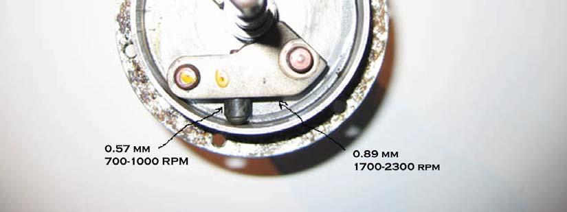
9 The above illustration shows the RPM ranges affected by each of the pin/spring sets. Two of the pin/spring sets were removed from this distributor but the RPM ranges for each set and its relative position in the mechanism is correct. Note the dab of yellow paint it is important. While you can't check linearity, you can check for max advance. At 5000 engine RPM you should see the A5/34 mark on the flywheel Advance Calibration You can measure these clearances with some narrow feeler gauges or a caliper. Once you figure out the sequence of spring/pin engagement, make sure the increase in gap is roughly linear. Not very accurate, but better than nothing. The clearances I measured are noted in the above illustration If you are using a Distributor Machine you will need to reassemble the distributor, install and gap the points, then operate the distributor through the 500 RPM to 3500 RPM at 500 RPM intervals (remember the distributor turns at on-half engine speed) and log the advance from the degree wheel on the distributor machine. You can them plot the advance curve either on a piece of graph paper or with a spreadsheet like Excel. Factory Test Numbers DIST RPM ADV +1% -1% Front1 Rear1 Front2 Rear2 Front3 Rear Deviation


10 Here is the actual plot from my distributors, after they were adjusted. The black line is the desired curve. The dotted lines are the allowable envelope. The red and blue lines are each one of my distributors. I can compensate for the fact that my curves are a little slower than the desired curve by advancing my static advance a couple of degrees. Notice that the maximum deviation between the two distributors is less than two degrees anywhere in the useful RPM range I think that is good enough since the factory envelope allows + or one degree. If you slide the curves to the left about 1.5 degrees my curves fit nicely in the envelope. So I adjust my static advance to compensate. The main thing here is that the curves for each distributor closely match one another. You don t want one bank of cylinders to be advanced or retarded with respect to the other at a specific RPM. Above is the factory graph (from the Owner s Manual) for reference:
11 Reassembly Points Installation When you install your points, you can see that the points base plate has elongated holes for the mounting screws. The whole points assembly can be moved 5 or 10 degrees back and forth. When the points open and the coil discharges you want to be sure the rotor is pointed directly at the brass conductor in the cap for that cylinder. If the points are in the wrong position, the rotor could be 5 or 10 degrees off being pointed directly at the post. Your engine will run, but not well. The slot corresponds with the exact position of the post in the cap for cylinder 1. Install the R1 points then reinstall the spider and bearing (otherwise the shaft will wobble and give erratic readings). Gap the points at If you are using a distributor machine, fine tune the dwell with the machine running at 500 RPM. Then check the points opening position against the slot in the distributor rim. This adjustment is best made in a distributor machine, but you can jury-rig a test: Get a 12v Extra Bright White LED (I get them from Radio Shack in the US for about $1 each) The reason you want an LED is that it acts like a strobethe light is instant on, instant off -unlike an incandescent bulb. Wire the LED through the points to a 12v source (battery). Tape it to the outside of the distributor case, right next to the slot in the rim of the distributor body. Install the rotor on the top of the shaft. Manually turn the distributor (clockwise, looking from the top). Watch the rotor, and it should pass the slot just as the light goes from on to off. Adjust the radial position of the points to achieve this. Both point gap and position affect this measurement, so you may have to adjust and check several times. Your distributor is now set up, unless you need to run the second set of points to effect the retarded spark at idle. I ll have a write-up on the second set of points soon.
Ignition Timing - Honda 180-Degree Twins
 Ignition Timing - Honda 180-Degree Twins First thing to do is make a quick test light - I used a 12 volt indicator bulb from a speedo. Test leads with alligator clips make hookup easy... The point plate
How I installed new brake pads on my i with Sport Package (should be fine for other E39 s) By Robert B.
 By Robert B.") How I installed new brake pads on my 1999 528i with Sport Package (should be fine for other E39 s) How I installed new brake pads on my 1999 528i with Sport Package (should be fine for other E39 s) By
How I installed new brake pads on my 1999 528i with Sport Package (should be fine for other E39 s) How I installed new brake pads on my 1999 528i with Sport Package (should be fine for other E39 s) By
Rebuilding the Power Steering Pump for a 2007 Honda Accord 4CYL
 Rebuilding the Power Steering Pump for a 2007 Honda Accord 4CYL Disclaimer: I have benefited greatly from others who have taken the time to post auto repair videos/tutorials online. To try and return the
 Solid State Ignition Replacement May 15, 2005 Introduction: There are two Tecumseh Solid State Ignitions ( SSI ) configurations we are concerned with here: The one on the left I call SSI Under for short
PORSCHE V r Valve Timing Instructions. Copyright 2009 Written by Mike Frye Edited my Adam G.
 PORSCHE 928 32V r Valve Timing Instructions Copyright 2009 Written by Mike Frye Edited my Adam G. Sections: Overview.3 Disclaimer/warnings/things to watch for 4 Terms and naming conventions used in this
Chapter 5 Part B: Ignition system - transistorised type
 5B 1 Chapter 5 Part B: Ignition system - transistorised type Contents Coil - testing........................................... 9 Distributor - overhaul..................................... 7 Distributor
Prerequisites: Shop Manual (recommended) pages 3-9 through 3-13.
 pages 3-9 through 3-13.") Prerequisites: Order your gaskets average about $25.00 bucks X 2 so $50.00 4NK-11193-00-00 Obtain a shim kit (Should have several 265 and 270s) (Some dealers will exchange) Obtain a Valve Bucket Tool YM-33961
Prerequisites: Order your gaskets average about $25.00 bucks X 2 so $50.00 4NK-11193-00-00 Obtain a shim kit (Should have several 265 and 270s) (Some dealers will exchange) Obtain a Valve Bucket Tool YM-33961
How to Install Your Chevy Distributor
 Porsche GTO BMW Corvette Ferrari Mercedes Mustang Alfa-Romeo 'Cuda Jaguar 442 Lotus GS Trans Am Shelby Delorean Charger Pantera Lars Grimsrud Musclecar Restoration 1285 Cressida Court Lafayette, CO 80026
*Some speedometers have these additional electronic connections. If yours does, then remove the smaller slotted screws shown.
 www.odometergears.com 1981-1985 240 Cable-Driven Speedometers (NOT for 1986 and later electronic units) http://www.davebarton.com/240-odometer-repair.html For this set of instructions below, I will not
AUTOMOTIVE ENGINEERING SECTION
 PURPOSE OF IGNITION SYSTEM The ignition system supplies high-voltage surges as high as 47,000 volts (in some electronic systems) to the spark plugs in the engine cylinders. These surges produce electric
N62 & N62-TU Valve Stem Seal Tool Kit
 N62 & N62-TU Valve Stem Seal Tool Kit Part #: AGA-N62-VST-K Problem: You have a smoking BMW due to bad valve stem seals. The valve stem seal problem is that the old valve stem seal becomes hard over time
The spacers can be made out of.750 round aluminum bar with a.3125 to.318 hole drilled in center.
 SECTION I : FRONT COVER INSTALLATION With Crankshaft, Camshaft and oil Galley plugs installed in engine, you need to verify that the front cover clears the oil galley plugs and fits on engine block. The
Roehrig Engineering, Inc.
 Roehrig Engineering, Inc. Home Contact Us Roehrig News New Products Products Software Downloads Technical Info Forums What Is a Shock Dynamometer? by Paul Haney, Sept. 9, 2004 Racers are beginning to realize
Ignition Installation Troubleshooting Tips/Frequently-Asked Questions
 Ignition Installation Troubleshooting Tips/Frequently-Asked Questions Warning: Reversing the red and black ignition wires will destroy the ignition module and void the warranty. The Hot-Spark module s
Installation Guide for the Electronic Ignition Distributor
 Installation Guide for the Electronic Ignition Distributor Remanufactured By East Coast Roadster East Coast Roadster: Ignition systems and accessories for Datsun Roadster fanatics! PLEASE, Call with any
Remove Air Cleaner Cover and. Filter
 Remove Air Cleaner Cover and Inspect paper filter for tears Foam pre-cleaner is washable if equipped Replace if necessary Filter Remove Trim Panel Pull throttle lever knob off Remove 3, 8mm screws Remove
Fanatec GT3RS V1 to GT3RS V2 Tutorial
 Fanatec GT3RS V1 to GT3RS V2 Tutorial by Roy Visser 1 How to update your Fanatec GT3RS V1 wheel to a GT3RS V2 wheel Welcome to this guided and detailed tutorial for upgrading your Fanatec GT3RS V1 wheel
Gearbox Assembly 101. Introduction. Before Beginning. By Mark Schutzer 4/13/06
 Gearbox Assembly 101 By Mark Schutzer 4/13/06 Introduction If you are planning to re-motor an old brass locomotive you may want to upgrade to a new gearbox at the same time. The early 60 s and 70 s gearboxes
CHAPTER 6 IGNITION SYSTEM
 CHAPTER 6 CHAPTER 6 IGNITION SYSTEM CONTENTS PAGE Faraday s Law 02 The magneto System 04 Dynamo/Alternator System 06 Distributor 08 Electronic System 10 Spark Plugs 12 IGNITION SYSTEM Faraday s Law The
Retro it Steering Column
 Retro it Steering Column INSTALLATION INSTRUCTIONS for 1976-86 CJ5 & CJ7 FOR PART NUMBER S: 1520800010, 1520800020, 1520800051, 1526800010, 1526800020, 1526800051 S I NCE 1986 Instruction # 8000000010
LJ20 Distributor - Disassembly Inspection Repair
 LJ20 Distributor - Disassembly Inspection Repair Old Codger New To Old Suzuki Jeeps The odometer on this 1972 LJ20 indicated the distributor had less than 10,000 miles of wear but during that time it had
I hope this guide helps you as much as Boomer Bob helped me. We re just sharing what we know to help out other folks. Best of luck! Phil C.
 A brief tutorial on swapping cams for the Victory Cross Roads and Cross Country on the Victory Freedom 106 inch V-Twin Engine with 6 speed over drive transmission Disclaimer: Swapping cams on a Victory
75 SERIES BILLET HEI DISTRIBUTORS
 INSTALLATION INSTRUCTIONS 75 SERIES BILLET HEI DISTRIBUTORS GENERAL INFORMATION Mallory 75 Series Distributors are similar to GM HEI distributors, but with many advantages over the OEM design, including:
1.6L 4-CYL - VIN [E]
![1.6L 4-CYL - VIN [E]](/thumbs/81/84172348.jpg "1.6L 4-CYL - VIN [E]") 1.6L 4-CYL - VIN [E] 1993 Nissan Sentra 1993 NISSAN ENGINES 1.6L 4-Cylinder NX, Sentra * PLEASE READ THIS FIRST * NOTE: For engine repair procedures not covered in this article, see ENGINE OVERHAUL PROCEDURES
1.6L 4-CYL - VIN [E] 1993 Nissan Sentra 1993 NISSAN ENGINES 1.6L 4-Cylinder NX, Sentra * PLEASE READ THIS FIRST * NOTE: For engine repair procedures not covered in this article, see ENGINE OVERHAUL PROCEDURES
T-3161-T Texas T Distributor
 T-3161-T Texas T Distributor NOTE: Please read completely through the instructions before installing your distributor. It will insure your installation goes smoothly. If you have installed a distributor
Performer Series Carburetor Rebuild Kit Catalog #1477 Models
 Please read these instructions carefully before attempting to rebuild your carburetor. Make sure to refer to your carburetor Owner s Manual for further information if need be. If you have any questions
Multi-tool 2CV / Visa
 Multi-tool 2CV / Visa For the professional 2CV specialist / perfectionist: The heart of the engine, the crankshaft and camshaft often needs a (partial) revision. There are many new 2CV parts, but for these
DIY: Repairing/Replacing the Timing Chain Tensioner
 DIY: Repairing/Replacing the Timing Chain Tensioner By Saki GT - February 8, 2012 [youtube=http://www.youtube.com/watch?v=24cil5_9yvq] The above video is an example of how a bad Timing Chain Tensioner
Some tips and tricks I learned from getting clutch out of vehicle Skoda Octavia year 2000
 Some tips and tricks I learned from getting clutch out of vehicle Skoda Octavia year 2000 Last change 2013-Oct-11 I bought Haynes manual for a starter. That s something well worth it s cost I believe.
INSTALLATION INSTRUCTIONS
 INSTALLATION INSTRUCTIONS INSTALLATION INSTRUCTIONS FOR A136 REAR DRUM TO DISC BRAKE CONVERSION KIT for 1970-75 Jeep, CJ SERIES with Dana 44 flanged axle Thank you for choosing STAINLESS STEEL BRAKES CORPORATION
DrVanos.com Stage II Installation Instructions. Tool rental is available with the purchase of a vanos kit *See website for more info*
 DrVanos.com Stage II Installation Instructions Special Tools Needed: Camshaft locking tool TDC Crank pin Sprocket turning tool Tool rental is available with the purchase of a vanos kit *See website for
Timing belt change. Timing belt change
 Timing belt change Put 2 new Gates T275 timing belts on today. Tensioner drilled smooth and tight with less than 16,000 miles on her decided not to change the tensioners just the belts. You'll need some
Backwater Performance Systems Large Vanguard Mikuni Twin Carburetor Kit
 Backwater Performance Systems Large Vanguard Mikuni Twin Carburetor Kit 1. Throttle Cable Twin (CKC-41) 2. Carburetor VM30mm (CKC-40) 3. Loctite 242.5mL (A-210) 4. Air Cleaner Filter 6000 (EC-86) 5. Rev
Crestline Dampening System. Installation Instructions. A.B. Dick 350, 360, 375 Single & Dual Lever Machines. X /01 Rev-A
 Crestline Dampening System Installation Instructions A.B. Dick 350, 360, 375 Single & Dual Lever Machines X88-20 01/01 Rev-A GENERAL INFORMATION ATTENTION CRESTLINE DAMPENER OWNER! Accel Graphic Systems
Ford 9 XD Aussie-Locker Install Instructions.
 Ford 9 XD-45831 Aussie-Locker Install Instructions. Before the install check the following. 1. Must be 31 spline 4-pinion carrier. 2. Must be an open carrier not a limited slip. 3. Refer to Ford or vehicle
GESOCO INDUSTRIES INC. FRANKLIN COUNTY AIRPORT 629 AIRPORT ROAD, SWANTON VT TEL FAX
 GESOCO INDUSTRIES INC. FRANKLIN COUNTY AIRPORT 629 AIRPORT ROAD, SWANTON VT 05488 TEL. 802-868-5633 E-MAIL gesoco@together.net FAX 802-868-4465 Date: 23 November 2001 Russian Magnetos, Ignition Systems
Though Indian s 111-cubic-inch engine delivers a
 TECH by Chris Maida Andrews Indian 111 Camshafts Part I: Removing the cams from the camshaft compartment Tools Needed Red Loctite Clean rags 6mm Allen 5/64" Allen 3/32" punch External circlip pliers Needlenose
Disco 3 Clock Spring / Rotary Coupler replacement
 Disco 3 Clock Spring / Rotary Coupler replacement I recently had to change my Clock spring and thought some folks may find it helpful to see what it entailed. I did lots of reading around but couldn t
Use Installation Procedure 1 when the crankshaft has NOT been rotated from the original position.
 2001 Blazer 4WD Applies to: 4.3L Report a problem with this article Removal Procedure Notice: There are two procedures available to install the distributor. Use Installation Procedure 1 when the crankshaft
How To Verify Your Valve/Crankshaft Timing & Set A Distributor.
 How To Verify Your Valve/Crankshaft Timing & Set A Distributor. If you don't have a good working knowledge of shop safety practices, DON'T ATTEMPT THIS! If you don't possess common sense or self preservation
Installing AMP-wiring in a New Beetle
 Installing AMP-wiring in a New Beetle Vehicle used: New Beetle 2.0i Type 9C (1999) Used set of cables: Dietz 35mm² power cable, double shielded Dietz chinch cable ( 35mm² Professional Line ) First of all:
Connecting the rear fog light on the A4 Jetta, while keeping the 5 Light Mod
 Connecting the rear fog light on the A4 Jetta, while keeping the 5 Light Mod DISCLAIMER: I'm human and make mistakes. If you spot one in this how to, tell me and I'll fix it This was done on my 99.5 Jetta.
Mirrored from:
 Mirrored from: http://www.wranglerforum.com/f274/install-synergy-suspension-ball-joints-write-up-147062.html 03-18-2012, 02:43 AM #1 SilverSport Supporting Member WF Supporting Member Install Synergy Suspension
Tri-Spark Ignition System Installation Triple Cylinder TRI-0001
 Tri-Spark Ignition System Installation Triple Cylinder TRI-0001 There are potentially lethal high voltages produced at the ignition coils and spark plugs, therefore every precaution must be taken to prevent
2001 V70 T5 ETM Removal and Cleaning Directions
 2001 V70 T5 ETM Removal and Cleaning Directions Howard Cheng howardc64@gmail.com 10/24/05 Version 1.4 Read this before you start I performed this ETM cleaning because I had gotten 2 reduced performance
DISTRIBUTORLESS IGNITION SYSTEM Installation and Adjustment Instructions
 DISTRIBUTORLESS IGNITION SYSTEM Installation and Adjustment Instructions 1.0 INTRODUCTION: Congratulations on your purchase of a Holley Distributorless Ignition System! Holley cannot and will not be responsible
Distributor: Service and Repair Distributor Replacement REMOVAL PROCEDURE
 2001 Chevy Truck S10/T10 Blazer 2WD V6-4.3L VIN W Copyright 2007, ALLDATA 9.50 Page 1 Distributor: Service and Repair Distributor Replacement REMOVAL PROCEDURE NOTE: There are two procedures available
PERFORMER RPM Camshaft/Lifters/Lube Kit CATALOG #7102 MODEL: c.i.d. Chevrolet V8, 1957 & later
 PERFORMER RPM Camshaft/Lifters/Lube Kit CATALOG #7102 MODEL: 262-400 c.i.d. Chevrolet V8, 1957 & later CAMSHAFT: Edelbrock Performer RPM camshafts are ground specifically for use with the corresponding
VALCON PLUS V-CAM SYSTEM STEP 1 INSTRUCTION MANUAL
 VALCON PLUS V-CAM SYSTEM STEP 1 INSTRUCTION MANUAL NAME OF PRODUCT USE RB26 V-CAM SYSTEM STEP1 AUTOMOBILE PARTS PART NUMBER 22007-AN002 TYPE A MAKE ENGINE YEAR REMARKS 22007-AN003 TYPE B NISSAN SKYLINE
Precision Degree Wheel Kit
 555-81621 Precision Degree Wheel Kit Instruction Booklet Instructions for 81621 Camshaft Degree Kit Thank you for purchasing the Jegs Camshaft Degree Kit. Please follow these detailed instructions to properly
This is a guide to assist you adjust the valve clearance on a 2l V6 MIVEC engine found in a Mitsubishi FTO GPX
 Adjusting the valve clearance on a 2L V6 FTO engine This is a guide to assist you adjust the valve clearance on a 2l V6 MIVEC engine found in a Mitsubishi FTO GPX Disclaimer: This guide is to assist you
2.2L 4-CYL - VIN [S]
![2.2L 4-CYL - VIN [S]](/thumbs/72/67564355.jpg "2.2L 4-CYL - VIN [S]") 2.2L 4-CYL - VIN [S] 1994 Toyota Celica 1994 ENGINES Toyota 2.2L 4-Cylinder Celica NOTE: For repair procedures not covered in this article, see ENGINE OVERHAUL PROCEDURES - GENERAL INFORMATION article
2.2L 4-CYL - VIN [S] 1994 Toyota Celica 1994 ENGINES Toyota 2.2L 4-Cylinder Celica NOTE: For repair procedures not covered in this article, see ENGINE OVERHAUL PROCEDURES - GENERAL INFORMATION article
Distributor Replacement
 Page 1 of 11 2002 Chevrolet Chevy K Silverado - 4WD Sierra, Silverado (VIN C/K) Service Manual Document ID: 690165 Distributor Replacement Removal Procedure Notice: There are two procedures available to
REPAIR MANUAL URW SERIES. URW-6, 8, 9, 10 & 12 Series Repair Manual
 REPAIR MANUAL URW SERIES URW-6, 8, 9, 10 & 12 Series Repair Manual Contents Page 1. Tools Needed for Repair 1 2. Disassembly and Reassembly of the Cam Casing 2-4 3. Disassembly and Reassembly of the Gear
PERFORMER RPM Camshaft/Lifters/Lube Kit CATALOG #7102 MODEL: c.i.d. Chevrolet V8, 1957 & later
 PERFORMER RPM Camshaft/Lifters/Lube Kit CATALOG #7102 MODEL: 262-400 c.i.d. Chevrolet V8, 1957 & later PLEASE study these instructions carefully before installing your new camshaft. If you have any questions
Installation Instructions Jeep CJ-7
 Retrofit Steering Column Installation Instructions 1976-86 Jeep CJ-7 For Part # s 1520800010, 152800020, 1520800051 www.ididitinc.com 610 S. Maumee St., Tecumseh, MI 49286 (517) 424-0577 (517) 424-7293
This LED flashtube kit covers models 400, 404, 500, 504, 600, 680 & 506.
 L.E.D. INSTRUCTIONS I D T S O T U B I R M O C R Y N A P Kit contains: This LED flashtube kit covers models 400, 404, 500, 504, 600, 680 & 506. For the power supply: 1-LED power supply circuit board, 2
Performer-Plus 5.0L Hydraulic Roller Lifter Camshaft only CATALOG #3722 MODEL: 5.0 Litre Ford V8, 1985 & later INSTRUCTIONS
 Performer-Plus 5.0L Hydraulic Roller Lifter Camshaft only CATALOG #3722 MODEL: 5.0 Litre Ford V8, 1985 & later INSTRUCTIONS PLEASE study these instructions carefully before installing your new camshaft.
Tri-Spark - Classic Triple Trident & R3 Installation Instructions
 Tri-Spark - Classic Triple Trident & R3 Installation Instructions TRI-0002 Copyright Tri-Spark 2015 Revised June 2015 Thank you for purchasing the Tri-Spark Classic Triple Ignition system. For your own
Tools needed: Here is a pic of the shift kit I used. It is a Transgo brand and as you can see, it just a bag full of springs and one valve.
 Before installing a shift kit, be sure the transmission is in good operating order. If your transmission is making noises, slipping, shifting bad or the fluid looks brown or smells burnt, take the transmission
Orientation and Conferencing Plan Stage 1
 Orientation and Conferencing Plan Stage 1 Orientation Ensure that you have read about using the plan in the Program Guide. Book summary Read the following summary to the student. Everyone plays with the
BOTTOM END SERVICE TOOLS SERVICE PRODUCTS ENGINE, CVT AND GEARBOX Subsection 10 (BOTTOM END)
") BOTTOM END SERVICE TOOLS Description Part Number Page CRANKCASE SUPPORT MAG/PTO... 529 036 031... 151 CRANKSHAFT LOCKING BOLT... 529 035 617... 154 DRIVE SHAFT OIL SEAL INSTALLER... 529 036 028... 143
BOTTOM END SERVICE TOOLS Description Part Number Page CRANKCASE SUPPORT MAG/PTO... 529 036 031... 151 CRANKSHAFT LOCKING BOLT... 529 035 617... 154 DRIVE SHAFT OIL SEAL INSTALLER... 529 036 028... 143
Before performing any on-vehicle adjustments to fuel or ignition systems, ensure engine mechanical condition is okay.
 Page 1 of 11 ARTICLE BEGINNING INTRODUCTION Introduction information not applicable. ENGINE MECHANICAL Before performing any on-vehicle adjustments to fuel or ignition systems, ensure engine mechanical
INSTALLATION INSTRUCTIONS for HI-1 and HI-2 MOTORCYCLE IGNITIONS. Part Numbers and INTRODUCTION COIL AND SPARK PLUG CABLE CONSIDERATIONS
 INSTALLATION INSTRUCTIONS for HI- and HI- MOTORCYCLE S Part Numbers 8-000 and 8-000 CAUTION: READ INSTRUCTIONS CAREFULLY BEFORE STARTING INSTALLATION INTRODUCTION Crane HI- and HI- ignition systems are
TORKER-PLUS Camshaft/Lifters/Lube Kit CATALOG #5002 MODEL: c.i.d. Chevrolet V8
 PLEASE study these instructions carefully before installing your new camshaft. If you have any questions or problems, do not hesitate to call our Technical Hotline at: 1-800-416-8628. CAMSHAFT: Edelbrock
INSTALLATION INSTRUCTIONS
 INSTALLATION INSTRUCTIONS REAR DRUM TO DISC BRAKE CONVERSION KIT A130 JEEP CJ SERIES W/AMC-20 REAR AXLES AND 5 x 5-1/2" BOLT CIRCLE Thank you for choosing STAINLESS STEEL BRAKES CORPORATION for your braking
DIY: Shiver Valve Check, Illustrated
 DIY: Shiver Valve Check, Illustrated By Petemoss, AF1 Forum Tools needed: 4mm allen wrench to remove all the fairing pieces 2.5mm allen wrench to remove battery holder 5mm allen wrench for valve cover
Mounting instructions for the '123ignition'
 Mounting instructions for the '123ignition' type : 123\GB-4-R-V for : most English 4 cylinder engines, 6 & 12 Volt, negative earth only! IMPORTANT Please read the entire instructions before you begin installation.
PORSCHE 928. PKT Installation 1.6. No air pump version. Air pump version
 PORSCHE 928 PKT Installation No air pump version Air pump version 1.6 Tools Torque wrench 10mm socket 12mm socket 13mm socket 5mm allen socket 6mm allen socket 8mm allen key Caliper Supplies Blue Loctite
Tach-Drive Distributor Reconditioning Joe Fisher PDF prepared by Dave Zuberer Link to Thread on the Corvette Forum (C1-C2)
") Tach-Drive Distributor Reconditioning Joe Fisher PDF prepared by Dave Zuberer Link to Thread on the Corvette Forum (C1-C2) I just finished two Corvette tach-drive distributors. One was a 71 small block
Tach-Drive Distributor Reconditioning Joe Fisher PDF prepared by Dave Zuberer Link to Thread on the Corvette Forum (C1-C2) I just finished two Corvette tach-drive distributors. One was a 71 small block
Roller Camshaft Installation
 Installation Instructions Roller Camshaft Installation For more information, see www.cranecams.com READ CAREFULLY AND COMPLETELY BEFORE INSTALLATION Prior to installation, immerse lifters in a premium
TSS Fit Kit Installation Instructions Timbersled Snow Bike System
 TSS Fit Kit Installation Instructions Timbersled Snow Bike System Information needed before you start: Read the entire installation instructions before starting. The instruction sheet is universal for
Mikuni RS Carburetor Conversion
 Mikuni RS Carburetor Conversion After putting your carbies on the bench or the kitchen table if the wife is out, you will see that the linkages may be in different positions depending on which brand of
List of tools: Jack Two Jack Stands Conventional Socket Set Liquid Collection pan Rear axle lubricant and friction modifier Rags for wiping up spills
 List of tools: Jack Two Jack Stands Conventional Socket Set Liquid Collection pan Rear axle lubricant and friction modifier Rags for wiping up spills 1. Jack car up Loosen wheel lugs first. Don t take
460cc Do-It-Yourself Assembly Guide
 2995 Coleman St North Las Vegas, NV 89032 702-530-7753 702-643-7517 FAX VegasCarts.com 460cc Do-It-Yourself Assembly Guide *DIY Engines do not come with a warranty, these kits are intended for experienced
VALVE ADJUSTMENT. To perform a valve adjustment, the engine must be cold: minimum of 4 hours after shutoff, overnight is preferable.
 VALVE ADJUSTMENT The following instructions cover valve adjustment on nonhydraulic (solid lifter) engines. Check the specification sheet on your vehicle to establish your specific engine. If not available,
June 23, 2014 Page 1
 My engine looks pretty clean but this fuel pump and fuel control assembly looked really nasty. I decided to partially tear them down and clean them up. This is what the asssembly looked like to begin with.
CHAPTER 11: FLYWHEEL, CLUTCH AND ALTERNATOR BACK ON
 CHAPTER 11: FLYWHEEL, CLUTCH AND ALTERNATOR BACK ON Posted on the Wildguzzi forum by Pete Roper: January 17, 2006: Contents: Assembling the engine. Flywheel, clutch and alternator back on. Pic 11-1: To
PERFORMER-PLUS CAMSHAFT / LIFTERS / LUBE KIT MODEL: 351-M/400 c.i.d. Ford V8 CATALOG #2172 INSTALLATION INSTRUCTIONS
 PERFORMER-PLUS CAMSHAFT / LIFTERS / LUBE KIT MODEL: 351-M/400 c.i.d. Ford V8 INSTALLATION INSTRUCTIONS Please study these instructions carefully before installing your new camshaft. If you have any questions
D - ADJUSTMENTS - 4-CYL
 D - ADJUSTMENTS - 4-CYL 1993 Toyota Celica 1993 ENGINE PERFORMANCE Toyota 4-Cylinder On-Vehicle Adjustments Celica ENGINE MECHANICAL Before performing any on-vehicle adjustments to fuel or ignition systems,
Required tools are: Parts list:
 BEW cam and lifters replacement procedure by zanzabar Jay Roberts, Petaluma, CA. (modified from engine timing belt replacement procedure from MOGolf as demonstrated on a 2004 Jetta). Required tools are:
Ford 8, 9 Small Bearing Installation Instructions Rear Disc Conversion
 Ford 8, 9 Small Bearing Installation Instructions Rear Disc Conversion This kit is for Ford 9 rear axles with the small (2.835 ) style bearing and Ford 8 rear ends. This kit is designed to work with axles
CAMSHAFT INSTALLATION INSTRUCTIONS FOR NISSAN KA24DE ENGINES W/DOUBLE ROW CHAIN (SEE LAST PAGE FOR USING JWT CAMS IN KA24DE W/SINGLE ROW CHAIN)
") 9/13 UPDATE CAMSHAFT INSTALLATION INSTRUCTIONS FOR NISSAN KA24DE ENGINES W/DOUBLE ROW CHAIN (SEE LAST PAGE FOR USING JWT CAMS IN KA24DE W/SINGLE ROW CHAIN) 1. It is highly recommended that an oil and filter
9/13 UPDATE CAMSHAFT INSTALLATION INSTRUCTIONS FOR NISSAN KA24DE ENGINES W/DOUBLE ROW CHAIN (SEE LAST PAGE FOR USING JWT CAMS IN KA24DE W/SINGLE ROW CHAIN) 1. It is highly recommended that an oil and filter
Version 1.4 Operating instructions Czech Republic
 Version 1.4 Operating instructions Czech Republic Please check updates of operating instructions at www.rotomotor.cz, that your engine has still the best care. (can happen important changes that will lead
DRIVE AXLE Volvo 960 DESCRIPTION & OPERATION AXLE IDENTIFICATION DRIVE AXLES Volvo Differentials & Axle Shafts
 DRIVE AXLE 1994 Volvo 960 1994 DRIVE AXLES Volvo Differentials & Axle Shafts 960 DESCRIPTION & OPERATION All 960 station wagon models use type 1041 rear axle assembly. All 960 4-door models use type 1045
M52tu-M54 VANOS Assembly & Timing Using G.A.S. Professional Cam Tool Kit
 Home BMW Solutions Porsche Solutions DIY Tech Engine Services Dyno Services Machining About Contact Store Tool Rental M52tu-M54 VANOS Assembly & Timing Using G.A.S. Professional Cam Tool Kit This procedure
JDM B16 & OBD0 HONDA DISTRIBUTOR REPAIR
 PDF Built By: tonyguns Source: Honda Tech JDM B16 & OBD0 HONDA DISTRIBUTOR REPAIR There are two things you should be checking before you begin. First, check the condition of the wiring harness. Pay close
Selected excerpts from the book: Lab Scopes: Introductory & Advanced. Steven McAfee
 Selected excerpts from the book: Lab Scopes: Introductory & Advanced Steven McAfee 1. 2. 3. 4. 5. 6. Excerpt from Chapter 1 Lab Scopes How do they work? (page 6) Excerpt from Chapter 3 Pattern Recognition
Mercedes Diesel Valve Adjustment Procedure
 1 of 30 5/30/2008 12:58 PM Home Cars for sale Trucks for sale Where we are Links to other diesel sites About us Why diesel? Diesel Videos How they work How they sound FAQ Dodge Diesel Maintenance tips,
Prusa i3 Printer Assembly Guide
 Prusa i3 Printer Assembly Guide Special thanks to Carlos Sanchez and Miguel Sanchez for the graphics. All graphics captured from their great animation: http://www.carlos-sanchez.com/ Prusa3/ For copyright
Replacing Valve Guide Oil Seals
 Many thanks to Sonicrete, Bucko and Lucksox who put me onto this whole way of replacing the valve guide oil seals without pulling the head or even taking the motor out of the frame. The key to it all is
2004 Chevy Truck Silverado WD V6-4.3L VIN X
 1 of 14 10/17/2013 8:32 PM 2004 Chevy Truck Silverado 1500 2WD V6-4.3L VIN X Vehicle» Powertrain Management» Ignition System» Distributor» Service and Repair» Distributor Replacement DISTRIBUTOR REPLACEMENT
installation manual 123\TUNE+-2CV
 installation manual 123\TUNE+-2CV Installation Instructions The 123\TUNE+-2CV is designed for the stock (BLACK) 2CV-coil STEP 1 Turn the ignition off. Remove the engine fan use a long 14 mm socket or
Potentiometer Replacement
 Potentiometer Replacement Tools Required: 2x 7/16 1/2 Nut Driver 1/8 Allen Wrench Small Straight Screwdriver Medium Phillips A potentiometer is a device which translates mechanical rotation into variable
Fiat X1/9 1500cc Engine Timing Belt Replacement, Cam Timing and Static Ignition Timing. Photos courtesy of Don Doan.
 Fiat X1/9 1500cc Engine Timing Belt Replacement, Cam Timing and Static Ignition Timing. Photos courtesy of Don Doan. Introduction This document outlines how to replace a timing belt on a Fiat X1/9 1500cc
MGA Twin Cam Engine Assembly.
 MGA Twin Cam Engine Assembly. The following article is a collection of notes of things to be observed in the assembling of MGA Twin Cam engines. To be read in conjunction with the Workshop Manual. It does
Series 1000 and Cutout
 17.15.Remove the belt from the tractor. NOTE: There were a small number of tractors made using a CVT drive and a 2-speed (L-H-N-R) GT transaxle. The belt must pass over the center mounted gear selector
Triumph Street Triple VSM Grip Heater Install
 Triumph Street Triple VSM Grip Heater Install Introduction: With winter fast approaching and with painful memories of last winter riding with the club it was time to do something about getting some grip
Installing the Wireless Charging upgrade kit in a 2018 XT5 (Platinum version)
") Installing the Wireless Charging upgrade kit in a 2018 XT5 (Platinum version) September 2, 2018 Tools needed: Wireless charger upgrade kit Plastic trim tools 7 mm nut driver Background: I purchased the
Installing the Wireless Charging upgrade kit in a 2018 XT5 (Platinum version) September 2, 2018 Tools needed: Wireless charger upgrade kit Plastic trim tools 7 mm nut driver Background: I purchased the
$1.00 FOR THE TQIO/RCIO
 $1.00 FOR THE TQIO/RCIO m mm HDBBYSHOP Champion Jay Halsey has an impressive track record. One of Jay's advantages is a whisper smooth tranny thanks to his dad, Jim. Now you can build a Halsey transmission!