Combiner Manual #OMBINER #OMBINER < 2* )NSTALLATION 7(&+12/ i 62/$5
|
|
|
- Posy Townsend
- 5 years ago
- Views:
Transcription


1 Combiner Manual i
2 ii Combiner Manual
3 Combiner Manual Copyright 2004 SMA America, Inc. All rights reserved. All rights reserved. No part of this document may be reproduced, stored in a retrieval system, or transmitted, in any form or by any means, electronic, mechanical, photographic, magnetic or otherwise, without the prior written permission of SMA America, Inc. SMA America makes no representations, express or implied, with respect to this documentation or any of the equipment and/or software it may describe, including (with no limitation) any implied warranties of utility, merchantability, or fitness for any particular purpose. All such warranties are expressly disclaimed. Neither SMA America nor its distributors or dealers shall be liable for any indirect, incidental, or consequential damages under any circumstances. (The exclusion of implied warranties may not apply in all cases under some statutes, and thus the above exclusion may not apply.) Specifications are subject to change without notice. Every attempt has been made to make this document complete, accurate and up-to-date. Readers are cautioned, however, that SMA America reserves the right to make changes without notice and shall not be responsible for any damages, including indirect, incidental or consequential damages, caused by reliance on the material presented, including, but not limited to, omissions, typographical errors, arithmetical errors or listing errors in the content material. Revision History Rev. No. Date By Description 1.0 Nov. 1, 2004 ES / JP Preliminary Release 1.1 Dec. 1, 2004 KS / JP First Release 1.2 Dec. 10, 2004 JP Torque Update 1.3 Feb. 09, 2005 JP Revised Specifications SMA America, Incorporated C Loma Rica Drive Grass Valley, California Tel Fax iii
4 Combiner Manual IMPORTANT SAFETY INSTRUCTIONS *SAVE THESE INSTRUCTIONS* This manual contains important instructions for the Combiner Box models SCCB and SCCB that must be followed during the installation and use of the Combiner Boxes. The Combiner Boxes are designed and tested according to international safety requirements, but as with all electrical and electronic equipment, certain precautions must be observed when installing the Combiner Boxes. To reduce the risk of personal injury and to ensure the safe installation and operation of the Combiner Boxes, you must carefully read and follow all instructions and warnings in this Installation Guide. Safety and Hazard Symbols This symbol is used to call attention to important information that you must have when installing and/or operating the Combiner Boxes. Failure to read and follow instructions marked with this symbol could result in serious injury and/or damage to the equipment. This symbol appears beside instructions and warnings that deal with dangerous voltages that can injure people who come in contact with them. Warnings WARNING: A Warning describes a hazard to equipment or personnel. It calls attention to a procedure or practice, which, if not correctly performed or adhered to, could result in damage to or destruction of part or all of the SMA equipment and/or other equipment connected to the SMA equipment or personal injury. Warnings may also be accompanied by one or more of the safety and hazard symbols described above to indicate the type of hazard described therein. Other Symbols In addition to the safety and hazard symbols described previously, the following symbol is also used in this Installation Guide: This symbol accompanies notes that call attention to supplementary information that you should know to ensure optimal operation of the system. iv
5 Combiner Manual Warranty All Combiner Boxes sold in the USA have a one-year warranty, as indicated on the warranty card included in the shipping container. For warranty coverage, or if you have questions about the Combiner Box warranty, contact SMA America at the address, telephone number, or Web site listed on page iii (to send , see the Contact section of the SMA America Web site: WARNING: All electrical installation must be done in accordance with the National Electrical Code ANSI/NFPA 70, local building codes and the requirements of the authority having jurisdiction. WARNING:To prevent electrical shock or injury, all wiring and commissioning procedures must be performed by qualified personnel. WARNING: Before installing or using the Combiner Box, read all of the instructions and warnings on the Combiner Box and in this Installation Guide. WARNING: PV arrays produce electrical energy when exposed to light and thus create an electrical shock hazard. This GROUND symbol marks areas in the Combiner Box for connecting equipment grounds only. v
6 Combiner Manual This page intentionally left blank. vi
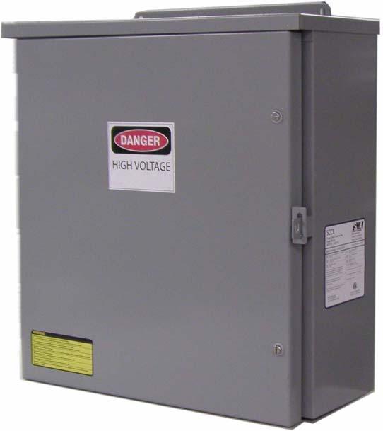
7 Combiner Manual Introduction Introduction SMA America has introduced a new line of PV combiner boxes designed for use with the Sunny Central family of inverters. Combiner Box features include: Listed to UL 1741 Simplified input and output wiring Compact, low-cost design Wall-mount NEMA 3R outdoor steel enclosure Reliable buss-work for combined high current conductors Unpacking and Inspection All SMA Combiner Boxes are thoroughly checked before they are packaged and shipped. Although they are shipped in sturdy packaging, damage can still occur during shipping and delivery. It is important to carefully inspect the shipping container and contents prior to installation. If you detect any external damage after unpacking, report the damage immediately to your SMA dealer and shipping company that delivered the unit. If it becomes necessary to return the Combiner, use the original packing material. If you need assistance in dealing with a damaged unit, contact SMA Input Circuit Configurations The SCCB Combiner Boxes are commonly available with 10 or 28 PV input circuits. Other sizes in between 10 and 28 circuits may be special ordered given sufficient lead time when ordering. Please contact SMA America for more information. 1
8 Installation Combiner Manual Installation Refer to Figure 1-1 for enclosure dimensions. Use appropriate hardware for the mounting surface. The weight of the unit is shown in the specification list. Figure 1-1 Combiner Enclosure Dimensions 2
9 Combiner Manual Wiring Wiring Input Wiring NOTE: The combiner enclosure is shipped with no entry holes. A knock-out is required for the appropriate conduit size. SMA recommends wire entry be made from the bottom, but there is no restriction, other than local code, for making wire entries from other locations in the enclosure. Refer to Figures 1-2 and 1-3 for the input and output wiring locations of the combiner box. PV positive conductors are wired into the outside fuse holder terminals. PV negative conductors are wired into the terminal busses located at the top of the combiner box. All PV safety ground conductors are wired into the terminal busses located at the bottom of the combiner box. Output Wiring The SCCB 28 circuit combiner boxes have a 420A DC fault current rating. When temperature and voltage drop adjustments are considered, the output conductor sizes can become quite large (500 mcm or greater) and difficult to manage. NEC article allows paralleling of conductors greater than 1/0 to achieve higher ampacities. The SCCB circuit combiner boxes provide output terminals for paralleling two conductors for the PV positive and negative, as well as the equipment ground conductors. Combiner Box Output Fusing If more than three combiner boxes are needed for one inverter, it may be necessary to fuse the combiner box output conductors. Please contact SMA America for further details. Refer to Figures 1-2 and 1-3 for the schematic of the combiner circuits. 3
10 Wiring Combiner Manual Figure 1-2 Combiner Box Schematic, SCCB
11 Combiner Manual Wiring Figure 1-3 Combiner Box Schematic, SCCB
12 Wiring Combiner Manual Fuse Sizing In any electrical system, fuses are used to protect wiring and equipment from excessive currents that can cause damage, heating or in extreme cases even fire. If the fuse rating is too small it could open during normal operation. If the fuse rating is too large, it cannot provide the needed protection. In PV systems, the minimum and maximum size of the series fuse is determined by the electrical ratings of the PV module as well as by UL and National Electrical Code (NEC) requirements. Be sure to consult with your PV module manufacturer for appropriate fuse ratings. The minimum size of fuses and wiring are calculated using the Short Circuit Current Rating (Isc) of the PV module. The NEC requires that all fuses and wiring be sized for a minimum of 1.56 times the Isc of the PV module used in the system. The proper size PV string fuse is determined by calculating 1.56 x Isc (of the PV module) and then rounding up to the next standard fuse size. Example: If the Isc of the PV module equals 6.9 Adc, then the fuse size is determined by 1.56 x 6.9 = The next standard fuse size would be a 12A, 600Vdc fuse. DC Disconnect Requirements NEC allows the use of fuse holders as a suitable means of disconnecting PV arrays for servicing. Additional DC disconnects external to the inverter may be required by the local authority having jurisdiction. WARNING: Never open a fuse holder while it is under load. Electrical arcing and damage to the fuse holder will occur if a fuse holder is opened under load. PV String Fuses The SCCB is shipped without PV string fuses. SMA America maintains stock of common fuse sizes for the SCCB products. The current rating of the fuse is dependent upon the specific PV module used in the PV array. Please contact SMA America to order the appropriate fuses for your project. 6
13 Combiner Manual Specifications Specifications SCCB (28 Circuit) Number of Inputs Positive Input Wire Size and Terminal Torque Value Negative Input Wire Size and Terminal Torque Value Max Input Fuse Rating Max Output Current Max Continuous Output Current Number of Outputs Output Wire Size Terminal Torque Value Enclosure Type Weight 28 Positive, 28 Negative 10 to 6 AWG 14 in-lb. 10 to 6 AWG 35 in-lb. 15 A, 600 V DC, Midget Class 420 A DC 340 A DC 2 Positive, 2 Negative 4/0 to 300 mcm 350 in-lb. 3R Rated 56 lbs. (approx.) SCCB (10 Circuit) Number of Inputs Positive Input Wire Size and Terminal Torque Value Negative Input Wire Size and Terminal Torque Value Max Input Fuse Rating Max Output Current Max Continuous Output Current Number of Outputs Output Wire Size Terminal Torque Value Enclosure Type Weight 10 Positive, 10 Negative 10 to 6 AWG 14 in-lb. 10 to 6 AWG 35 in-lb. 15 A, 600 V DC, Midget Class 150 A DC 120 A DC 2 Positive, 2 Negative 4/0 to 300 mcm 350 in-lb. 3R Rated 48 lbs. (approx.) 7
14 Specifications Combiner Manual 8
15

16
SBCB-6, SCCB-12, 28, 52 6 to 52 Circuit Combiner Boxes
 Combiner Manual SBCB-6, SCCB-12, 28, 52 6 to 52 Circuit Combiner Boxes User Manual U.S. Version 2.4 DOC-CBUG-01 i ii Combiner Manual Combiner Manual Copyright 2012 SMA America, LLC. All rights reserved.
Disconnect Combiner Box Installation Manual
 Disconnect Combiner Box Installation Manual SolarBOS, Inc. 310 Stealth Court Livermore CA 94551-9552 925-456-7744 ph. 925-456-7710 fax www.solarbos.com Copyright 2008 SolarBOS, Inc. All rights reserved.
Contactor Combiner Box Installation Manual
 Contactor Combiner Box Installation Manual SolarBOS, Inc. 310 Stealth Court Livermore CA 94551-9552 925-456-7744 ph. 925-456-7710 fax www.solarbos.com Copyright 2008 SolarBOS, Inc. All rights reserved.
Combiner Box Installation Manual
 Combiner Box Installation Manual SolarBOS, Inc. 310 Stealth Court Livermore CA 94551 925-456-7744 ph. 925-456-7755 fax www.solarbos.com Copyright 2008 SolarBOS, Inc. All rights reserved. All rights reserved.
Sunny Boy Accessories SUNNY BOY COMBINER BOX TLUS SBCBTL6
 Sunny Boy Accessories SUNNY BOY COMBINER BOX TLUS SBCBTL6 Installation Guide SBCBTLUS-IUS094510 IMUS-SBCBTLUS Version 1.0 US SMA America, LLC Legal Restrictions Copyright 2010 SMA America, LLC. All rights
Sunny Central Accessories SUNNY CENTRAL STRING-MONITOR US
 Sunny Central Accessories SUNNY CENTRAL STRING-MONITOR US Technical Description SSMUS-TUS094511 98-4001411 Version 1.1 US Copyright 2009 SMA America, Inc. All rights reserved. No part of this document
Solar Inverter SUNNY BOY 5000US / 6000US / 7000US
 Solar Inverter SUNNY BOY 5000US / 6000US / 7000US Installation Guide SB50US-70US-IUS091924 TBUS-SB50_60_70US Version 2.4 US Copyright 2009 SMA America, Inc. All rights reserved. No part of this document
Installation Guide. Trace Combiner Box 6
 Installation Guide Trace Combiner Box 6 About Xantrex Xantrex Technology Inc., is a world-leading supplier of advanced power electronics and controls with products from 50 watt portables to 1 megawatt
SunLink PV System Disconnect with Arc Fault Detection Installation and Operations Manual
 Combiner Box Installation & Operations Manual SunLink PV System Disconnect with Arc Fault Detection Installation and Operations Manual TABLE OF CONTENTS Notices and Safety Precautions Pages 1-2 Combiner
PV Inverter SUNNY BOY 2000HF-US / 2500HF-US / 3000HF-US
 PV Inverter SUNNY BOY 2000HF-US / 2500HF-US / 3000HF-US Installation Guide SB20-30HF-US-IA-en-12 IMUS-SB20-30HFUS Version 1.2 CA US SMA America, LLC Copyright 2012 SMA America, LLC. All rights reserved.
RSDCOM. Installation and Operation Guide. Commercial Rapid Shutdown Combiner. DOCR Published March 2017 Revision C English
 f Commercial Rapid Shutdown Combiner RSDCOM Installation and Operation Guide Models: RSDCOM M-PC-1Z-4F RSDCOM M-PC-1Z-4F-24V RSDCOM M-PC-1Z-5F RSDCOM M-PC-1Z-5F-24V RSDCOM M-FG-2Z-4F RSDCOM M-FG-2Z-4F-24V
System Monitoring SUNNY SENSORBOX
 System Monitoring SUNNY SENSORBOX Installation Manual Sensorbox-eng-IA-IUS-112515 98-0003915 Version 1.5 CA US SMA America, LLC Legal Restrictions Copyright 2011 SMA America, LLC. All rights reserved.
Micro Inverter with Communication Unit SUNNY BOY 240-US SUNNY MULTIGATE-US
 Micro Inverter with Communication Unit SUNNY BOY 240-US SUNNY MULTIGATE-US Installation Manual SMG-SB240US-IA-en-11 Version 1.1 CA US Legal Provisions Legal Provisions Copyright 2013. All rights reserved.
Monicon Instruments Co., Ltd. CHR-1285/2485 CHR-1285/2485 BATTERY CHARGER
 CHR-1285/2485 BATTERY CHARGER TEL:886-4-2238-0698 FAX:886-4-2238-0891 Web Site:http://www.monicon.com.tw E-mail:sales@monicon.com.tw Copyright 2007 Monicon Instruments Co., Ltd. All right reserved. Contents
Model LA 4300 Time Delay OFF Controller
 ISIMET LA Series Model LA 4300 Time Delay OFF Controller Installation, Operation and Maintenance Manual Application: The Time Delay OFF Controller operates as a single output controller where the application
Model LA 4100 Time Delay OFF Controller
 ISIMET LA Series Model LA 4100 Time Delay OFF Controller Installation, Operation and Maintenance Manual Application: The Time Delay OFF Controller operates as a single output controller where the application
CONTACTS RELAY TESTER 66249
 RELAY TESTER 66249 These instructions accompanying the product are the original instructions. This document is part of the product, keep it for the life of the product passing it on to any subsequent holder
PVI 1800/PVI Residential/Commercial Grid-Tied Photovoltaic Inverter WARRANTY MANUAL. Subject to Change REV , Solectria Renewables
 PVI 1800/PVI 2500 WARRANTY MANUAL Residential/Commercial Grid-Tied Photovoltaic Inverter 2009, Solectria Renewables Subject to Change REV 10.09 1 Product Warranty & RMA Policy 1.1 Warranty Policy The Solectria
Model LA 4400 Time Delay OFF Controller
 ISIMET LA Series Model LA 4400 Time Delay OFF Controller Installation, Operation and Maintenance Manual Application: The Time Delay OFF Controller with integral 24-hr. programmable time clock operates
Model HPX60 Series Automatic Battery Charger User s Manual Rev. 1.0 October 17, 2006
 B R A N D Model HPX60 Series Automatic Battery Charger User s Manual Rev. 1.0 October 17, 2006 For Sales, Support and Service phone: 407-331-4793 fax: 407-331-4708 website: www.xenotronix.com email: information@xenotronix.com
Mechanical Spiral Sensor
 Installation Manual Model 6005-1 Mechanical Spiral Sensor No part of this instruction manual may be reproduced, by any means, without the written consent of Geokon, Inc. The information contained herein
Dimensions 12/800N 12/1200N D. DC to AC Power Inverters. OWNERS MANUAL for Models: OWNERS MANUAL April ISO 9001:2000 Certified Company
 Manufacturer of Dimensions Inverters 4467 White Bear Parkway St. Paul, MN 55110 Phone: 651-653-7000 Fax: 651-653-7600 E-mail: inverterinfo@sensata.com Web: www.dimensions.sensata.com OWNERS MANUAL April
Installation Manual. Rev
 Installation Manual ChargePro 620 Charging Station is a trademark of SemaConnect, Inc. All other products or services mentioned are the trademarks, service marks, registered trademarks or registered service
Outdoor Nema Enclosure For Dotworkz CoolDome Power Supply Product Code: NM-CDPS. User Manual
 Outdoor Nema Enclosure For Dotworkz CoolDome Power Supply Product Code: NM-CDPS User Manual Revision June 2008 Outdoor Nema Enclosure For Dotworkz CoolDome Power Supply LIMITED WARRANTY FOR DOTWORKZ SYSTEMS
OWNERS MANUAL JANUARY 2007 ISO
 Manufacturer of Dimensions TM Inverters 4467 White Bear Parkway St. Paul, MN 55110 Phone: 651-653-7000 Fax: 651-653-7600 E-mail: inverterinfo@sensata.com Web: www.dimensions.sensata.com OWNERS MANUAL JANUARY
Patient Care Facility
 ISIMET Patient Care Facility DLA Controller Individual Room Configuration Style 1 W/ Ver 4.41 pcb & Pulse Relay pcb Installation, Operations, Start-up and Maintenance Instructions Meets all Standards for
MIL-24/2600Q MIL-24/3200DQ
 Manufacturer of Dimensions TM Inverters 4467 White Bear Parkway St. Paul, MN 55110 Phone: 651-653-7000 Fax: 651-653-7600 E-mail: inverterinfo@sensata.com Web: www.dimensions.sensata.com 121473B OWNER'S
CONTACTS EGR VALVE TESTER 66248
 EGR VALVE TESTER 66248 These instructions accompanying the product are the original instructions. This document is part of the product, keep it for the life of the product passing it on to any subsequent
END USER TERMS OF USE
 END USER TERMS OF USE The following is the End Users Terms of Use as it currently appears in the Mobileye User Manual and Warranty information. This is here for your review and information; it is subject
Drug Testing Labs. Style 2 W/ Ver 4.41 pcb & Pulse Relay pcb(s) Installation, Operations, Start-up and Maintenance Instructions
 Installation, Operations, Start-up and Maintenance Instructions") ISIMET Drug Testing Labs DLA Controller Style 2 W/ Ver 4.41 pcb & Pulse Relay pcb(s) Installation, Operations, Start-up and Maintenance Instructions Meets all Standards for Canadian Industrial Control
ISIMET Drug Testing Labs DLA Controller Style 2 W/ Ver 4.41 pcb & Pulse Relay pcb(s) Installation, Operations, Start-up and Maintenance Instructions Meets all Standards for Canadian Industrial Control
Sunny Island 4248U SOLARTECHNOLOGY. Installation & Operating Instructions. Battery Inverter/Charger for Stand-Alone and Back-up Applications
 SI4248U Installation Guide Sunny Island 4248U Battery Inverter/Charger for Stand-Alone and Back-up Applications SOLARTECHNOLOGY Installation & Operating Instructions i ii SI4248U Installation Guide SI4248U
F-4600 INLINE ULTRASONIC FLOW METER Installation and Operation Guide
 F-4600 INLINE ULTRASONIC FLOW METER Installation and Operation Guide 11451 Belcher Road South, Largo, FL 33773 USA Tel +1 (727) 447-6140 Fax +1 (727) 442-5699 1054-7 / 34405 www.onicon.com sales@onicon.com
PHOTOVOLTAIC ELECTRICAL POWER SYSTEMS INSPECTOR/INSTALLER CHECKLIST
 PHOTOVOLTAIC ELECTRICAL POWER SYSTEMS INSPECTOR/INSTALLER CHECKLIST The following checklist is an outline of the general requirements found in the 2005 National Electrical Code (NEC) Article 690 for Photovoltaic
General Installation Manual 2007 Sanyo Electric Co., Ltd. All Rights Reserved 6/15/07
 General Installation Manual for SANYO HIT Photovoltaic Modules. Please read this manual completely before use or installation of SANYO modules. This manual applies to the following models: HIP-205BA3,
Installation Manual AUTOMATIC BACKUP UNIT
 Installation Manual AUTOMATIC BACKUP UNIT BUUxx-US-10 SBS-ABU-xx-US-10 ENGLISH SBS-ABU-xx-US-IA-en-12 Version 1.2 Legal Provisions SMA Solar Technology AG Legal Provisions The information contained in
Copyright 2012 DelSolar Co. Ltd MQWRD installation manual-iec Ver. 1.4
 INSTALLATION MANUAL IEC Version www.delsolarpv.com Copyright 2012 DelSolar Co. Ltd MQWRD-01-14--installation manual-iec Ver. 1.4 Content General information 1 Safety precaution for installing solar PV
Installation Manual AXITEC SOLAR MODULES
 Installation Manual AXITEC SOLAR MODULES 1/12 AXITEC INSTALLATION USA 160504 Table of Contents INTRODUCTION... 3 DISCLAIMER OF LIABILITY... 3 GENERAL INFORMATION... 3 SAFETY... 3 1 WARNING AND CAUTION...
PVI 60KW, PVI 82KW, PVI 95KW
 PVI 60KW PVI 82KW PVI 95KW WARRANTY MANUAL Commercial, Grid-Tied Photovoltaic Inverters 2008, Solectria Renewables LLC Subject to Change DOC-020099 rev 024 1 1 Product Warranty & RMA Policy Warranty Policy
Patient Care Facility
 ISIMET Patient Care Facility DLA Controller Individual Room Configuration Style 1 W/ Ver 4.41 pcb & Pulse Relay pcb Installation, Operations, Start-up and Maintenance Instructions Meets all Standards for
Drug Testing Labs. Style 2 W/ Ver 4.41 pcb & Pulse Relay pcb(s) Installation, Operations, Start-up and Maintenance Instructions
 Installation, Operations, Start-up and Maintenance Instructions") ISIMET Drug Testing Labs DLA Controller Style 2 W/ Ver 4.41 pcb & Pulse Relay pcb(s) Installation, Operations, Start-up and Maintenance Instructions Meets all Standards for Canadian Industrial Control
ISIMET Drug Testing Labs DLA Controller Style 2 W/ Ver 4.41 pcb & Pulse Relay pcb(s) Installation, Operations, Start-up and Maintenance Instructions Meets all Standards for Canadian Industrial Control
Acme Conduit Entry. String Combiner/Pass-Through. FOR PHOTOVOLTAIC INSTALLATION Installation Manual
 Acme Conduit Entry String Combiner/Pass-Through FOR PHOTOVOLTAIC INSTALLATION Installation Manual Table of Contents Important Safety Instructions -----------------------------------------------------------------------------------------------------------
Central Inverter SUNNY CENTRAL 500U
 Central Inverter SUNNY CENTRL 500U Installation Guide SC500U-IUS093411 98-4014611 Version 1.1 US SM Solar Technology G Copyright 2009 SM merica, Inc. ll rights reserved. No part of this document may be
Off-Grid Inverter SUNNY ISLAND 4548-US/6048-US
 Off-Grid Inverter SUNNY ISLAND 4548-US/6048-US Technical description SI4548_6048-US-TB_en-13 Version 1.3 US SMA America, LLC Legal Provisions Legal Provisions Copyright 2013 SMA America, LLC. All rights
INSTALLATION GUIDE AND USER MANUAL
 Electric Vehicle Charging Station INSTALLATION GUIDE AND USER MANUAL Model: 30A EVoCharge EVSE Model Number: EV072-300-001A Product Safety Certification: UL and cul Listed Description: SAE J1772 AC Level
Installation Manual Model 3800/3810
 Installation Manual Model 3800/3810 Thermistors & Thermistor Strings No part of this instruction manual may be reproduced, by any means, without the written consent of Geokon, Inc. The information contained
User Manual. Solar Charge Controller 3KW
 User Manual Solar Charge Controller 3KW 1 CONTENTS 1 ABOUT THIS MANUAL... 3 1.1 Purpose... 3 1.2 Scope... 3 1.3 SAFETY INSTRUCTIONS... 3 2 INTRODUCTION... 4 2.1 Features... 4 2.2 Product Overview... 5
Micro-Air Corporation Route 526 Allentown, NJ 08501
 EasyStart 366 Commercial (board-only) Model ASY-366-X05 (36000 BTU, 3 ton) ASY-366-X06 (72000 BTU, 6 ton) Micro-Air Corporation www.microair.net 124 Route 526 help@microair.net Allentown, NJ 08501 Contents
Owner's Manual. GenReady Load Center and Transfer Switch. This manual should remain with the unit. Model Numbers. GenReady Basic Panelboard
 Owner's Manual GenReady Load Center and Transfer Switch 0054480 0054510 0054490 0054520 0054530 0054540 0054560 Model Numbers GenReady Basic Panelboard GenReady Advanced Panelboard with Operator GenReady
PD404-AN V analog control 4 Channel x 500 W Dimmer & Switch Packs ANALOG 0-10 V. Serial Number
 0-10V analog control 4 Channel x 500 W Dimmer & Switch Packs ANALOG 0-10 V 4 circuit Analog 1-10V 4 x 4 A. Dimmer pack Serial Number Dimmers Indicators Digital Lighting Systems,Inc Info@digitallighting.com
TESTER SET SOCKET & VOLTAGE
 SOCKET & VOLTAGE TESTER SET 82384 These instructions accompanying the product are the original instructions. This document is part of the product, keep it for the life of the product passing it on to any
PY-11 Voltage & Continuity Tester
 PY-11 Voltage & Continuity Tester Users Manual PY-11 Voltage & Continuity Tester English Users Manual May 2010, Rev.1 2010 Amprobe Test Tools. All rights reserved. Printed in China Limited Warranty and
ANTI-SYPHON VALVE INSTALLATION GUIDE
 ANTI-SYPHON VALVE INSTALLATION GUIDE The information in this publication is provided for reference only. While every effort has been made to ensure the reliability and accuracy of the information contained
Assembly Instructions Signature Choral Riser 3-Step Model
 Assembly Instructions Signature Choral Riser 3-Step Model Contents Important User Information...........................2 General...2 Manufacturer...2 Intended Use...2 Warranty...2 Safety Precautions.................................3
CPS Energy Balancer. Version: 1.0
 CPS Energy Balancer Version: 1.0 CHINT POWER SYSTEMS AMERICA CO., LTD. Address: 700 International Parkway, Suite 102 Richardson, Texas Zip Code: 75081 Web: www.chintpower.com/na Email: americasales@chintpower.com
Cabling for power, control, and video must be run to the installation site before the mount is installed.
 User Installation User Guide Guide & Operation Manual V940D V-20B-A-2 V940D Mounting Kits Mounting Pole Mounting Kits Adapter X532-11-00 Vicon Industries Inc. does not warrant that the functions contained
Operations Manual. Zero Speed Switch Sensor Model ZS09P
 Zero Speed Switch Sensor Model ZS09P The must be referred to for correct installation. Failure to comply with the shall void all warranties and liabilities. Overview The Phares Electronics Model ZS09P
Operator s Manual. Fairbanks FH Series by Fairbanks Scales, Inc. All rights reserved. . Revision 1 06/2017
 Operator s Manual Fairbanks FH Series 2017 by Fairbanks Scales, Inc. All rights reserved 51393. Revision 1 06/2017 Amendment Record Fairbanks FH Series Operator s Manual Operator s Manual Document 51393
GEatom306KHF-5U Three-phase Grid-Tied Battery Inverter. Version 1.1. Global Mainstream Dynamic Energy Technology Ltd. 1
 GEatom306KHF-5U Three-phase Grid-Tied Battery Inverter Version 1.1 Global Mainstream Dynamic Energy Technology Ltd. 1 Content Prelude... 4 1. Safety... 5 1.1 How to Use This Manual... 5 1.2 Safety Rules...
 OPERATING MANUAL: L/S VARIABLE-SPEED MODULAR DRIVES Model Nos. Pump Drive 07559-00 with Pump Head 07516-00 07559-00 07559-05 07559-10 07559-15 A-1299-7331 Edition 01 (US & Canada only) Toll Free 1-800-MASTERFLEX
NEO-DYN MODEL 100P ENCLOSURE 7 ADJUSTABLE EXPLOSION-PROOF PRESSURE SWITCH
 NEO-DYN MODEL 100P ENCLOSURE 7 ADJUSTABLE EXPLOSION-PROOF PRESSURE SWITCH INSTALLATION AND OPERATION MANUAL PN 610-0006 Rev E WARNING CAUTION SPECIAL CONDITIONS FOR SAFE USE NOTE Manual No. 610-0006 Rev
CPS 3Phs String Inverters NEC 2014 Compliance
 Application Note: NEC 2014 Compliance Revision: 062016 CPS 3Phs String Inverters NEC 2014 Compliance This application note describes the major changes within the NFPA 70, National Electric Code, specifically
Installation Manual SMA SPEEDWIRE/WEBCONNECT DATA MODULE
 Installation Manual SMA SPEEDWIRE/WEBCONNECT DATA MODULE A B FA: FA: xxxxx xxxxx SER: SER: xx xx SPWDM-10.BG1 SPWDM-10.BG1 SWWEBCONDM-IA-US_en-11 Version 1.1 AMERICAN ENGLISH SMA America, LLC Legal Provisions
DCCB. Installation Guide. Sine Wave Plus DC Conduit Box (DCCB)
") DCCB Installation Guide Sine Wave Plus DC Conduit Box (DCCB) Installation Guide Sine Wave Plus DC Conduit Box (DCCB) Installation Guide About Xantrex Xantrex Technology Inc. is a world-leading supplier
DCCB Installation Guide Sine Wave Plus DC Conduit Box (DCCB) Installation Guide Sine Wave Plus DC Conduit Box (DCCB) Installation Guide About Xantrex Xantrex Technology Inc. is a world-leading supplier
GS-IOB-120/240VAC. Input/Output/Bypass Assembly. Installation Instructions. Purpose. Scope. Requirements. Grounding Instructions
 GS-IOB-120/240VAC Input/Output/Bypass Assembly Installation Instructions Purpose This document provides information on how to install the Input/Output/Bypass Assembly needed for a 120/240 Vac configuration
PMA INTAKE FILTER SCREEN INSTALLATION GUIDE
 PMA INTAKE FILTER SCREEN INSTALLATION GUIDE The information in this publication is provided for reference only. While every effort has been made to ensure the reliability and accuracy of the information
CP-250E-60/72-208/240-MC4 Microinverter with Modular Trunk Cable
 CP-250E-60/72-208/240-MC4 Microinverter with Modular Trunk Cable Chilicon Power Aug 2016 1 CONTENTS CP-250E Microinverter System... 3 The CP-100 Cortex Gateway... 3 Important Safety Information... 4 Inverter
OWNERS MANUAL JANUARY 2007 ISO
 Manufacturer of Dimensions TM Inverters 4467 White Bear Parkway St. Paul, MN 55110 Phone: 651-653-7000 Fax: 651-653-7600 E-mail: inverterinfo@sensata.com Web: www.dimensions.sensata.com 121231B OWNERS
Patron Call System. Scope s DataPage II Lite & NexCall Coaster. Operators/Installation Manual
 Scope s DataPage II Lite & NexCall Coaster Operators/Installation Manual PREFACE Important Installation Information It is the purchasers responsibility to determine the suitability of this equipment and
DC to AC Power Inverters
 Manufacturer of Dimensions TM Inverters 4467 White Bear Parkway St. Paul, MN 55110 Phone: 651-653-7000 Fax: 651-653-7600 E-mail: inverterinfo@sensata.com Web: www.dimensions.sensata.com ISO 9001:2000 Certified
1 AMP CURRENT SOURCE
 1 AMP CURRENT SOURCE CS-2000-U CS-2000-E USER MANUAL BC BIOMEDICAL CS-2000 SERIES TABLE OF CONTENTS WARNINGS, CAUTIONS, NOTICES... ii DESCRIPTION... 1 LAYOUT... 2 OPERATION... 4 TESTING... 6 MANUAL REVISIONS...
INSTALLATION GUIDE AND USER MANUAL
 Electric Vehicle Charging Station INSTALLATION GUIDE AND USER MANUAL SAE J1772 AC Level 2 EVSE Model: 30A EVoCharge EVSE Wall Mount P/N: EV072-300-001A Version 2.0 IMPORTANT Read this manual thoroughly
DC to AC Power Inverters
 Manufacturer of Dimensions TM Inverters 4467 White Bear Parkway St. Paul, MN 55110 Phone: 651-653-7000 Fax: 651-653-7600 E-mail: inverterinfo@sensata.com Web: www.dimensions.sensata.com 121114C OWNERS
Residential Transition Box. Model RU-1. Specifications. Electrical
 Residential Transition Box Model RU-1 Model RU-1 transition box provides a quick, simple, and easy transition between a microinverter trunk cable and stranded wire. Using only a single flathead screwdriver,
SunWize SWPB Series Solar Modules GENERAL INSTALLATION & USER GUIDE
 SunWize SWPB Series Solar Modules GENERAL INSTALLATION & USER GUIDE Introduction This guide contains application and user safety information you should become familiar with before using your SWPB series
SUNTURA SOLAR TRACKER
 WindyNation SUNTURA SOLAR TRACKER SOT-TRKS-NF User s Manual Page 1 of 10 WindyNation 08/09/2012 Table of Contents 1 Introduction... 3 1.1 Limited Warranty... 3 1.2 Restrictions... 3 1.3 Warranty Claims
Solar Power Installation Application
 Solar Power Installation Application This Form must be filled out and submitted to Logan City Light and Power Department and given authorization to proceed PRIOR to installing a solar system. Also, please
Wenger Corporation 2011 Printed in USA 08/11 Part #158E006-02
 Owner s Manual Conductor s Podium COntents Warranty.......................................... 2 Important User Information............................ 2 General....................................... 2
INSTALLATION MANUAL.
 INSTALLATION MANUAL D6M_BxA Series : D6M_B1A / D6M_B2A / D6M_B3A / D6M_B5A D6M_AxA Series : D6M_A1A / D6M_A2A / D6M_A3A / D6M_A5A D6P_BxA Series : D6P_B1A / D6P_B2A / D6P_B3A / D6P_B5A D6P_AxA Series :
Installation Manual SMA SPEEDWIRE/WEBCONNECT DATA MODULE
 Installation Manual SMA SPEEDWIRE/WEBCONNECT DATA MODULE A B FA: FA: xxxxx xxxxx SER: SER: xx xx SPWDM-10.BG1 SPWDM-10.BG1 SWWEBCONDM-IA-US_en-13 Version 1.3 AMERICAN ENGLISH Legal Provisions SMA America,
Solar PV Standard Electrical Plan
 *** Provide this document to the inspector along with ALL system installation instructions *** Project Address: Permit Number: SCOPE: Standard plan for installation of solar PV systems utilizing 2 wire
Power Inverter 400 MW Owner s Manual
 Power Inverter 400 MW 1204 Owner s Manual For safe and optimum performance, the Power Inverter must be used properly. Carefully read and follow all instructions and guidelines in this manual and give special
Installation Guide Document N Cleanroom Mirrors Copyright 2016 Terra Universal Inc. All rights reserved. Revised November 2016
 Document N0. 1800-09 Copyright 2016 Terra Universal Inc. All rights reserved. Revised November 2016 Terra Universal, Inc. TerraUniversal.com 800 S. Raymond Ave. Fullerton, CA 92831 TEL: (714) 578-6000
Assembly Instructions
 Assembly Instructions Kid s Wheelbarrow Model # 84-8 Picture Similar KETTLER International Inc. 355 London Bridge Road Virginia Beach, VA 3453 USA www.kettlerusa.com / parts@kettlerusa.com / 866-804-0440
OnBoard Drum Major Podium
 Assembly and Owner s Manual OnBoard Drum Major Podium CONTENTS CONTENTS................................................................................. 1 SAFETY...................................................................................
PSX-240 Enclosed Autotransformer Installation Manual
 PSX-240 Enclosed Autotransformer Installation Manual IMPORTANT SAFETY INSTRUCTIONS SAVE THESE INSTRUCTIONS! This manual contains important instructions for the OutBack PSX-240 Autotransformer. All of the
RECHARGE STATION OPERATION MANUAL. Version
 RECHARGE STATION OPERATION MANUAL Version 1.0-0712 2014 by VirTra Inc. All Rights Reserved. VirTra, the VirTra logo are either registered trademarks or trademarks of VirTra in the United States and/or
High Performance Output Sine Wave Filter Installation, Operation, and Maintenance Manual
 High Performance Output Sine Wave Filter Installation, Operation, and Maintenance Manual TCI, LLC W132 N10611 Grant Drive Germantown, Wisconsin 53022 Phone: 414-357-4480 Fax: 414-357-4484 Helpline: 800-TCI-8282
COOPER POWER SERIES. K-Limiter back-up current-limiting fuse installation instructions. Fusing Equipment MN132010EN
 Fusing Equipment MN132010EN Effective February 2016 Supersedes S240-64A-1 October 1998 COOPER POWER K-Limiter back-up current-limiting fuse installation instructions SERIES DISCLAIMER OF WARRANTIES AND
PowerWorx Power Distribution Products Select Series Circuit Breaker for ±24 or ±48 Vdc User Manual
 PowerWorx Power Distribution Products Select Series Circuit Breaker for ±24 or ±48 Vdc User Manual ADCP-80-580 Issue 3 11/2010 17943-A Circuit Breaker for ±24 or ±48 Vdc 1474485 Rev C Preface COPYRIGHT
TECHNICAL BRIEF Americas
 TECHNICAL BRIEF Americas Design Considerations When AC Coupling IQ Micros to Battery-Based Systems Overview AC coupling allows use of Enphase Microinverters with battery-based inverter systems. These applications
Nota Conductor s Chair
 Assembly and Operation Instructions Nota Conductor s Chair CONTENTS Important User Information...........................2 General......................................2 Manufacturer.................................2
Easy Weigh ADVANCED COUNTING SCALE MODEL: AC-100 OWNER S MANUAL VER 1.00
 Easy Weigh OWNER S MANUAL MODEL: AC-100 ADVANCED COUNTING SCALE VER 1.00 TABLE OF CONTENTS SPECIFICATIONS... 1 NOMENCLATURE... 1 FUNCTION KEYS... 2 DISPLAY... 3 ACCURACY SPECIFICATIONS... 4 UNPACKING &
GENERAL INFORMATION. INSTRUCTIONS FOR 500A Lithium Jump Starter
 INSTRUCTIONS FOR 500A Lithium Jump Starter Stock No.15067 Part No.LJS136 IMPORTANT: PLEASE READ THESE INSTRUCTIONS CAREFULLY TO ENSURE THE SAFE AND EFFECTIVE USE OF THIS PRODUCT. GENERAL INFORMATION These
CP /240-MC4 User Manual
 CP-250-60-208/240-MC4 User Manual Chilicon Power LLC Dec 2015 1 CONTENTS Important Safety Instructions... 3 Safety Instructions... 3 CP-250 Microinverter System Introduction... 4 Inverter Label Information...
SUNTURA HD SOLAR TRACKER
 WindyNation SUNTURA HD SOLAR TRACKER SOT-TRKS-NFHD User s Manual Page 1 of 11 WindyNation 08/09/2012 Table of Contents 1! Introduction... 3! 1.1! Limited Warranty... 3! 1.2! Restrictions... 3! 1.3! Warranty
Matrix APAX. 380V-415V 50Hz TECHNICAL REFERENCE MANUAL
 Matrix APAX 380V-415V 50Hz TECHNICAL REFERENCE MANUAL WARNING High Voltage! Only a qualified electrician can carry out the electrical installation of this filter. Quick Reference ❶ Performance Data Pages
360 Watt Charge Controller
 Owner s Manual & Safety Instructions Save This Manual Keep this manual for the safety warnings and precautions, assembly, operating, inspection, maintenance and cleaning procedures. Write the product s
FLEX-ING TM DISPENSER HOSES INSTALLATION GUIDE
 FLEX-ING TM DISPENSER HOSES INSTALLATION GUIDE The information in this publication is provided for reference only. While every effort has been made to ensure the reliability and accuracy of the information
SUPPLEMENTAL CORRECTION SHEET FOR SOLAR PHOTOVOLTAIC SYSTEMS - ELECTRICAL
 SUPPLEMENTAL CORRECTION SHEET FOR SOLAR PHOTOVOLTAIC SYSTEMS - ELECTRICAL This is intended to provide uniform application of the codes by the plan check staff and to help the public apply the codes correctly.
TIC 300 PRO. Users Manual Mode d emploi Bedienungshandbuch Manual d uso Manual de uso. Non Contact AC Voltage Detector. High Energy Tic Tracer
 TIC 300 PRO High Energy Tic Tracer Non Contact AC Voltage Detector Users Manual Mode d emploi Bedienungshandbuch Manual d uso Manual de uso TIC 300 PRO High Energy Tic Tracer Non Contact AC Voltage Detector