Derailment Detector Assembly
|
|
|
- Justin Malone
- 5 years ago
- Views:
Transcription
1 Derailment Detector Assembly
2 Every attempt has been made to ensure that this documentation is as accurate and up-to-date as possible. However, Vertical Express assumes no liability for consequences, directly or indirectly, resulting from any error or omission. The material contained herein is subject to revision. Please report any problems with this manual to Vertical Express, P.O. Box 2019, Memphis, Tennessee Vertical Express P.O. Box 2019 Memphis, Tennessee Vertical Express. All rights reserved. Published November, 2011 First Edition Printed in the United States of America Manual Number: v.1.1
3 Derailment Detector Contents Contents Safety Precautions Terms in This Manual General Safety Electrical Safety Mechanical Safety Handling Shipping Arrival of Equipment Installation Diagrams Installation Wiring Wiring Tests Replacement Parts T-Style Rail C7 Formed Rail Printed in USA November,
4 Contents Derailment Detector This page intentionally left blank. 2 Vertical Express
5 Derailment Detector Safety Precautions IMPORTANT! Safety Precautions Read this page before any work is performed on elevator equipment. The procedures contained in this manual are intended for the use of qualified elevator personnel. In the interest of your personal safety and the safety of others, do not attempt any procedure that you are not qualified to perform. All procedures must be accomplished in accordance with the applicable rules in the latest edition of the National Electrical Code, the latest edition of ASME A17.1, and any governing local codes. Terms in This Manual CAUTION statements identify conditions that may result in damage to the equipment or other property if improper procedures are followed. WARNING statements identify conditions that may result in personal injury if improper procedures are followed. General Safety Before applying power to the controller, check that all factory wire connections are tight on relays, contactors, fuse blocks, resistors, and terminals on cards and DIN rail terminals. Connections loosened during shipment may cause damage or intermittent operation. Other specific warnings and cautions are found where applicable and do not appear in this summary. See the Elevator Industry Field Employees Safety Handbook for electrical equipment safety information on installation and service. Electrical Safety All wiring must be in accordance with the National Electrical Code and be consistent with all state and local codes. Use the Proper Fuse To avoid fire hazards, use only a fuse of the correct type, voltage, and current rating. See the job specific drawings sheet (Power Supplies) for fusing information. Electric shocks can cause personal injury or loss of life. Circuit breakers, switches, and fuses may not disconnect all power to the equipment. Always refer to the wiring diagrams. Whether the AC supply is grounded or not, high voltage will be present at many points. Printed Circuit Cards Printed circuit boards may be damaged if removed or installed in the circuit while applying power. Before installation and/or removing printed circuit boards, secure all power. Always store and ship printed circuit cards in separate static bags. Printed in USA November,
6 Safety Precautions Electrical Safety (continued) Mainline Disconnect Derailment Detector Unless otherwise directed, always Turn OFF, Lock, and Tag out the mainline disconnect to remove power from elevator equipment. Before proceeding, confirm that the equipment is de-energized with a volt meter. Refer to the Vertical Express Employees Safety and Accident Prevention Program Manual for the required procedure. Test Equipment Safety Always refer to manufacturers instruction book for proper test equipment operation and adjustments. Megger or buzzer-type continuity testers can damage electronic components. Connection of devices such as voltmeters on certain low level analog circuits may degrade electronic system performance. Always use a voltmeter with a minimum impedance of 1M Ohm/Volt. A digital voltmeter is recommended. When Power Is On To avoid personal injury, do not touch exposed electrical connections or components while power is ON. Mechanical Safety See the Elevator Industry Field Employees Safety Handbook for mechanical equipment safety information on installation and service. 4 Vertical Express
7 Derailment Detector Safety Precautions Static Protection Guidelines IMPORTANT! Read this page before working with electronic circuit boards. Elevator control systems use a number of electronic cards to control various functions of the elevator. These cards have components that are extremely sensitive to static electricity and are susceptible to damage by static discharge. Immediate and long-term operation of an electronic-based system depends upon the proper handling and shipping of its cards. For this reason, the factory bases warranty decisions on the guidelines below. Handling Cards shipped from the factory in separate static bags must remain in the bags until time for installation. Anti-static protection devices, such as wrist straps with ground wire, are required when handling circuit boards. Cards must not be placed on any surface without adequate static protection. Only handle circuit cards by their edges, and only after discharging personal static electricity to a grounding source. DO NOT touch the components or traces on the circuit card. Extra care must be taken when handling individual, discrete components such as EPROMS (which do not have circuit card traces and components for suppression). Shipping Complete the included board discrepancy sheet. Any card returned to the factory must be packaged in a static bag designed for the card. Any card returned to the factory must be packaged in a shipping carton designed for the card. Peanuts and styrofoam are unacceptable packing materials. Note: Refer to the Vertical Express Replacement Parts Catalog to order extra static bags and shipping cartons for each card. Failure to adhere to the above guidelines will VOID the card warranty! Arrival of Equipment Receiving Upon arrival of the equipment, inspect it for damage. Promptly report all visible damage to the carrier. All shipping damage claims must be filed with the carrier. Storing During storage in a warehouse or on the elevator job site, precautions should be taken to protect the equipment from dust, dirt, moisture, and temperature extremes. Revision Change Bars Each revised page included in this manual will have a vertical line (change bar) to the left of the text that has been added or changed. The example at the left of this paragraph shows the size and position of the revision change bar. Printed in USA November,
8 Safety Precautions Derailment Detector This page intentionally left blank. 6 Vertical Express
9 Derailment Detector Installation Diagrams Installation Diagrams Verify which type of rail application is to be installed, and reference the applicable figure. Clip, 8# Forged Rail C L CWT Rails 15# Rail (A) Flat Washer.625 Z (used instead of.250 thick flat washer) (B) (2.125) (C) Sensor Ring (each side of cwt.) Top Rail Mount 1/2-90º Electrical Connection Sliding Shoe Option Detail Rope Shackle Top mount (install as high on rail as possible) Top Retainer Plate Left CWT Rail Grounding Washer (on 2 shackles only) Connector Bracket Right CWT Rail Clevis Assy (SeeNote1) To Controller 1/2 thinwall & 90_ connector To Controller Tape both ends of cable (Typ.) #16 Insulated Wire stripped at the end and Clamped to Cable (must make and electrical connection) Clip, Wire Rope Cable Spring Assy (See Note 1) Bottom Rail Mount 5 Bottom Retainer Plate 11 min. to Pit Floor when on Compressed Buffer 8 to Pit Floor (SeeNote1) Note 1: If bottom of CWT is less than 20 above pit floor when on compressed buffer, mount bottom bracket 1 above pit floor. Install Clevis Assy. at the bottom and spring assy at the top. Travel A B C <= 250 Ft > 250 Ft Figure 1 - Derailment Detector - T-Rail Installation without Counterweight Safety Printed in USA November,
10 Installation Diagrams Derailment Detector Installation Diagrams (continued) Clip, 8# Forged Rail 15# Rail (A) Flat Washer.625 Z (used instead of.250 thick flat washer) (B) ( ) Sensor Ring (each side of cwt.) Face of rail (C) Top Rail Mount 1/2-90º Electrical Connection Sliding Shoe Option Detail Top Retainer Plate Rope Shackle Left CWT Rail Grounding Washer (on 2 shackles only) Connector Bracket Right CWT Rail Top mount (install as high on rail as possible) To Controller 1/2 thinwall & 90_ connector Clip, Wire Rope To Controller Tape both ends of cable (Typ.) Cable Spring Assy (See Note 1) Clevis Assy (See Note 1) #16 Insulated Wire stripped at the end and Clamped to Cable (must make and electrical connection) Bottom Rail Mount Bottom Retainer Plate 11 min. to Pit Floor when on Compressed Buffer Note 1: If bottom of CWT is less than 20 above pit floor when on compressed buffer, mount bottom bracket 1 above pit floor. Install Clevis Assy. at the bottom and spring assy at the top. Note 2: 9 minimum required from centerline of counterweight rail to inside of guard. 5 8 to Pit Floor (SeeNote1) Travel A B C <= 250 Ft > 250 Ft Figure 2 - Derailment Detector - T-Rail Installation with Counterweight Safety 8 Vertical Express
11 Derailment Detector Installation Diagrams Installation Diagrams (continued) Clip, Sliding, Formed Rail C7 Rail (A) Flat Washer.625 Z (used instead of.250 thick flat washer) (B) (C) Sensor Ring (each side of cwt.) Top Rail Mount 43/8 1/2-90º Electrical Connection Rope Shackle Top mount (install as high on rail as possible) Top Retainer Plate Left CWT Rail Grounding Washer (on 2 shackles only) Right CWT Rail Connector Bracket To Controller 1/2 thinwall & 90_ connector Cable Cross Connection To Controller Clevis Assy (See Note 1) Tape up both ends of cable (Typ.) Spring Assy (SeeNote1) Formed Rail 5 Retainer Plate 11 min. to Pit Floor when on Compressed Buffer 8 to Pit Floor (Typ.) (SeeNote1) Bottom Rail Mount Note 1: If bottom of CWT is less than 20 above pit floor when on compressed buffer, mount bottom bracket 1 above pit floor. Install Clevis Assy. at the bottom and spring assy at the top. Travel A B C <= 250 Ft > 250 Ft Figure 3 - Derailment Detector - C7 Formed Rail Installation Printed in USA November,
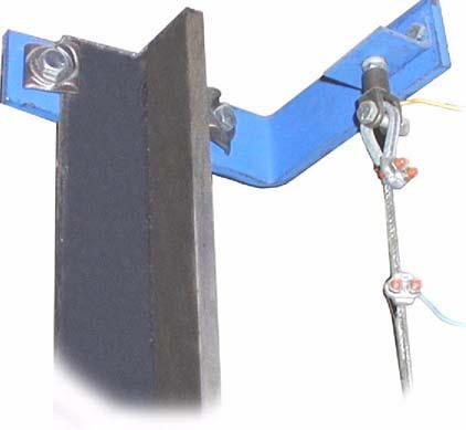
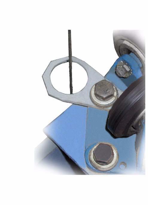
12 Installation Derailment Detector Installation 1. Check for adequate clearance between the counterweight and cab or the counterweight and wall. Note: The minimum clearance required to accommodate the detector is 2 1/4 inches. 2. Install a retainer plate under each roller or slide guide base (as applicable). 3. Verify the proper location for the sensor rings, and ensure that they will fit the counterweight. 4. Install two sensor rings (one on each side) at the counterweight. See Figure 4. a. Remove the appropriate bolt and washer. b. Discard the special 1/4-inch thick flat washer. c. Re-install the bolt, a replacement standard 5/8-inch flat washer, and the sensor ring. Figure 4 - Sensor Rings (C7 Formed Sensors Shown) 5. Install one grounding washer on each of any two counterweight rope shackles. Note: Do not install the bushing on the shackles with the grounding washers. 6. Install top rail mounts at the top of each counterweight rail. See Figure 5. For T-Rails with CWT Safety For T-Rails without CWT Safety and C7 Formed Rails Figure 5 - Rail Mounts 10 Vertical Express
 Clevis Thimble Figure 6 - Clevis Assembly at Top Rail Mount 8.")
13 Derailment Detector Installation (continued) 7. Attach the clevis assembly and bracket to the inside of the rail mount. See Figure 6. Installation Hex Head Cap Screw Flat Washer Rail Mount Insulator Jam Nut (Tighten nut firmly against clevis) Clevis Thimble Figure 6 - Clevis Assembly at Top Rail Mount 8. Attach the electrical connector bracket to the outside of the rail mount. 9. If the bottom of the counterweight is NOT less than 20 inches above the pit floor when on compressed buffer, move on to Step If the bottom of the counterweight is less than 20 inches above the pit floor when on compressed buffer: a. Mount the bottom rail mount 1 inch above the pit floor. b. Install the clevis assembly at the bottom, and the spring assembly at the top. Note: Keep the spring assembly as high as possible at a place 8 inches below the ceiling, and no less than 1/2-inch between the rail mount and the rail top. 11. Thread each cable up through the large hole in the sensors on the bottom and top of the counterweight, and then around the thimble at the top rail mount. Secure the cable with two cable clips. Note: Allow exactly 6 feet of additional length on one cable for cross connection. 12. Install the cable cross-connection with sufficient slack to allow each cable to hang plumb. Use two (2) cable clips on each side. 13. Install the bottom rail mounts 8 inches from the pit floor. 14. Mount the spring assemblies to the bottom rail mount. Make sure that the insulator is installed between the cable connecting rod and the rail mount. See Figure 7 on page 12 for the remaining steps in this procedure. 15. Pull the cable around the thimble, compress the spring to one-half of its length, and secure with (2) two cable clips 16. Repeat for the opposite side. Printed in USA November,
14 Wiring Installation (continued) Derailment Detector 17. Install a 16 gauge insulated wire to one side of the top rail mounted cables. a. Strip the end of the wire. b. Electrically attach the wire to the cable. 18. Connect the opposite end of the 16 gauge wire to the appropriate controller terminal. 19. Check and adjust the position of the sensors, and then center them on the cable. 20. Run the car through the hoistway, and ensure that the cable remains centered in the sensor hole. Cable Thimble Tighten nut firmly against clevis Connecting Rod Clevis Must be electrically isolated from the rail mount. Bottom rail mount Insulator Spring Nut.375 (Lock nut firmly in place) Figure 7 - Spring Assembly Wiring Wiring Tests 1. Verify that all mechanical and electrical installation has been completed. See Figure 8 on page 13 for all steps in this procedure. 2. Reset the circuit breaker. 3. Run the car Up and Down at contract speed several times to make sure the cables do not short out on the sensors during normal service. 4. Run the car to the top landing. 5. Turn the controller door switch to OFF, and the Auto/Inspection switch to INSPECTION. 6. With the I/O Screen displayed, select the proper car in IMS. 7. Right-click on the I/O Screen, and select METERED LOGIC from the pull-down menu. 8. From the pit, deflect one cable to the sensor and verify that the CWD input goes low (turns gray), on the IMS I/O Screen. 9. Reset the counterweight derailment circuit breaker, and then repeat Step 8 for the other cable. 12 Vertical Express
15 Derailment Detector Wiring Wiring Tests (continued) 10. Exit the pit, and reset the counterweight derailment circuit breaker. 11. Turn the Auto/Inspection switch to AUTO with the door switch remaining OFF. 12. Right-click on the IMS I/O Screen for the car being tested, and then select ENABLE I/O INJECT from the pull-down menu. 13. Click on the red box (in the upper left hand corner block of the I/O screen) for the car being tested. Note: The box should turn blue, which will turn off the I/O in the CPU. 14. Use the IMS Car Remote FAST to enter a car call near the bottom landing. 15. Wait until the car reaches high speed, and then click the CWD input on the I/O screen until the input turns blue. 16. Verify that the operation is correct for counterweight derailment. 17. Click on the CWD input until the input turns gray. Note: The input will turn gray for a short period and then turn red, the proper state if the counterweight derailment circuit breaker is reset. 18. Right-click on the I/O screen, and select Disable I/O Inject. 19. With the doors OFF, run the car several floors and verify proper elevator operation. 20. Return the elevator to service. 24VAC Rectifier Detector Assembly CW1 CW2 R1 Counterweight Grounding Apparatus Derailment Cable R2 NOTE: Circuit resistance 1-5 Ohms per 100 ft. of travel Figure 8 - Derailment Detector Assembly Wiring Diagram Printed in USA November,
16 Replacement Parts Derailment Detector Replacement Parts T-Style Rail CL CWT Rails Left CWT Rail Right CWT Rail ITEM PART NO. PRINT NO. DESCRIPTION Spring and Clevis Assembly with mounting bracket Aircraft Cable 1/8" Clip, Wire Rope Clevis Assembly with mounting bracket Bracket for Electrical Connector Washer, LWHR 3/8" C Nut, NH 3/8" Z Screw, CSH 3/8" x 1 1/4" Z Grounding Washer Washer, FWA, 5/8" Z Rail Mount without CWT Safety Rail Mount with CWT Safety Sensor without CWT Safety <= 250 ft Sensor without CWT Safety > 250 ft Sensor with CWT Safety <= 250 ft Sensor with CWT Safety > 250 ft. 14 Vertical Express
17 Derailment Detector Replacement Parts C7 Formed Rail C7 Rail CL CWT Rails Left CWT Rail Right CWT Rail ITEM PART NO. PRINT NO. DESCRIPTION Spring and Clevis Assembly with mounting bracket Aircraft Cable 1/8" Clip, Wire Rope Clevis Assembly with mounting bracket Bracket for Electrical Connector Washer, LWHR 3/8" C Nut, NH 3/8" Z Screw, CSH 3/8" x 1 1/4" Z Grounding Washer Washer, FWA, 5/8" Z Rail Mount BA1 Sensor <= 250 ft. 736BB1 Sensor > 250 ft. Printed in USA November,
18 Replacement Parts Derailment Detector This page intentionally left blank. 16 Vertical Express
19
20 Vertical Express P.O. Box 2019 Memphis, TN Tel: (866) (toll-free) Fax: (901) All illustrations and specifications are based on information in effect at the time of publication approval. Vertical Express reserves the right to change specification or designs and to discontinue items without prior notification or obligation. v.y.m. Copyright 2011 Vertical Express
Overspeed Adjustable Valve
 Overspeed Adjustable Valve Every attempt has been made to ensure that this documentation is as accurate and up-to-date as possible. However, Vertical Express assumes no liability for consequences, directly
Removable Applied Panel Mounting System
 Removable Applied Panel Mounting System Every attempt has been made to ensure that this documentation is as accurate and up-to-date as possible. However, Vertical Express assumes no liability for consequences,
Door Restrictor Assembly. Model R2
 Door Restrictor Assembly Model R2 Every attempt has been made to ensure that this documentation is as accurate and up-to-date as possible. However, Vertical Express assumes no liability for consequences,
LED Downlight Ceiling Fixtures
 ED Downlight Ceiling Fixtures Every attempt has been made to ensure that this documentation is as accurate and up-to-date as possible. However, Vertical Express assumes no liability for consequences, directly
Trimline Car and Sling
 Trimline Car and Sling Every attempt has been made to ensure that this documentation is as accurate and up-to-date as possible. However, Vertical Express assumes no liability for consequences, directly
GD-1 / GD-2 Sheave Brake
 GD-1 / GD-2 Sheave Brake Every attempt has been made to ensure that this documentation is as accurate and up-to-date as possible. However, Vertical Express assumes no liability for consequences, directly
Matrix APAX. 380V-415V 50Hz TECHNICAL REFERENCE MANUAL
 Matrix APAX 380V-415V 50Hz TECHNICAL REFERENCE MANUAL WARNING High Voltage! Only a qualified electrician can carry out the electrical installation of this filter. Quick Reference ❶ Performance Data Pages
Installation Instructions Electric Heaters 5 20 kw
 Small Packaged Products 2 to 5 Tons Accessory Electric Heaters Cancels: IIK 564A-24-2 IIK 564A-24- -02 Installation Instructions Electric Heaters 5 20 kw NOTE: Read the entire instruction manual before
Installation Instructions Electric Heaters 5 20 kw
 Small Packaged Products to 5 Tons Accessory Electric Heaters Cancels: IIK 564A--1 IIK 564A-- 11-01 Installation Instructions Electric Heaters 5 0 kw NOTE: Read the entire instruction manual before starting
Installation Instructions
 NOTE: Read the entire instruction manual before starting the installation. This symbol indicates a change since the last issue. SAFETY CONSIDERATIONS Installing and servicing air conditioning equipment
Digitrip Retrofit System for ITE K-3000, K-3000 S, K-4000 and K-4000 S Breakers
 Supersedes IL 33-858-4 Dated 05/02 Digitrip Retrofit System for ITE K-3000, K-3000 S, K-4000 and K-4000 S Breakers Digitrip Retrofit System for ITE K-3000, Digitrip Retrofit System for ITE K-3000, K-3000
Caution Improper installation could result in tape failure, mounting hardware, and reader. Please read instructions before installing!
 Elgo Sensor Mounting Motion High Speed Landing/Positioning System The encoded tape used for the landing system is suspended between two mounting brackets that attach to the car rail using forged clips
Instruction Manual AVTM for. Strip Chart Recorder Catalog Nos and
 AVTM220003 Rev. B January 2003 Instruction Manual AVTM220003 for DC µa Strip Chart Recorder Catalog Nos. 220003 and 220003-47 PO Box 9007 Valley Forge, PA 19485-1007 U.S.A. 610-676-8500 Shipping Address:
SIEMENS. XJ-L Busway Systems. Storage, Installation and Maintenance Instructions for... Piece No. 32-J Rev 3
 SIEMENS XJ-L Busway Systems Storage, Installation and Maintenance Instructions for... Piece No. 32-J-1010-01 Rev 3 ~DANGER Hazardous voltages and exposed electrical conductors will cause death, serious
REFERENCE MANUAL FORM: MX-TRM-E REL REV MTE
 Matrix APAX 380V-415V 50Hz TECHNICAL REFERENCE MANUAL FORM: MX-TRM-E REL. September 2014 REV. 002 2014 MTE Corporation WARNING High Voltage! Only a qualified electrician can carry out the electrical installation
OPERATIONS AND APPLICATIONS MANUAL MODEL NUMBER PM6. 6 KV DC HIGH POTENTIAL TESTER WITH MEGOHMMETER Version 2.0
 OPERATIONS AND APPLICATIONS MANUAL MODEL NUMBER PM6 6 KV DC HIGH POTENTIAL TESTER WITH MEGOHMMETER Version 2.0 TABLE OF CONTENTS Section Number DANGER PRODUCT INFORMATION 1 -SAFETY AND CAUTION NOTES -DESCRIPTION
Instruction, LS-EDGE Installation
 LS-EDGE Positioning System The LS-EDGE positioning system uses hall-effect sensors and perforated steel tape to report position as the car moves through the hoistway. 5.5-inch magnets are used at each
MAINTENANCE EVALUATION CHECKLIST ELECTRIC ELEVATORS
 Manufacturer: Model: Evaluation Performed By: INTRODUCTION: This checklist will enable the user to make an objective appraisal of the condition of the equipment. Given the variety and complexity of the
INSTRUCTION MANUAL L WIND CONE
 Cooper Industries DOCUMENT September 29, 2009 Revision B Crouse-Hinds Division Crouse-Hinds Airport Lighting Products 1200 Kennedy Road Windsor, CT 06095 860 683-4300 Fax 860 683-4354 Title: INSTRUCTION
MODELS TSX AND TSX-S SINGLE DUCT ROUND AIR TERMINALS
 MODELS TSX AND TSX-S SINGLE DUCT ROUND AIR TERMINALS INSTALLATION OPERATION & MAINTENANCE New Release Form 130.13-NOM4 (908) In conjunction with the use of these instructions, obtain and refer to the construction,
JEEVES. JEEVES Installation Manual. Installation Manual The Easiest Do-It-Yourself Dumbwaiter on the Market
 1 888-323-8755 www.nwlifts.com JEEVES Installation Manual The Easiest Do-It-Yourself Dumbwaiter on the Market This manual will cover the installation procedure step-by-step. The installation of this dumbwaiter
MODELS SGX AND SSX SINGLE DUCT ROUND AIR TERMINALS
 BY JOHNSON CONTROLS INSTALLATION OPERATION & MAINTENANCE MODELS SGX AND SSX SINGLE DUCT ROUND AIR TERMINALS New Release Form ET130.13-NOM4 (908) In conjunction with the use of these instructions, obtain
SPC-PANEL Simplex, Single Phase Pump Control Panel
 Pump Installation and Service Manual SPC-PANEL Simplex, Single Phase Pump Control Panel Pump Controls for 2 HP Grinder Pumps NOTE! To the installer: Please make sure you provide this manual to the owner
INSTALLATION INSTRUCTIONS AMBASSADOR DRUM OVERHEAD SERIES 100 DUMBWAITER
 INSTALLATION INSTRUCTIONS AMBASSADOR DRUM OVERHEAD SERIES 100 DUMBWAITER The installation of Matot Drum Dumbwaiters should only be performed by qualified, experienced, and trained elevator installers.
Matrix AP 400V 690V INSTALLATION GUIDE. Quick Reference. ❶ How to Install Pages 6 20 ❷ Startup/Troubleshooting Pages WARNING
 Matrix AP 400V 690V INSTALLATION GUIDE FORM: MAP-IG-E REL. May 2017 REV. 002 2017 MTE Corporation WARNING High Voltage! Only a qualified electrician can carry out the electrical installation of this filter.
Service Instructions. Syntron Light-Capacity Electromagnetic Model: F-T01-A DF-T01-A
 Service Instructions Syntron Light-Capacity Electromagnetic Model: F-T01-A DF-T01-A Service Instructions Syntron Light-Capacity Electromagnetic Vibrating Feeders Models: F-T01-A and DF-T01-A Contents Page
FIELD CONNECTIONS FOR YK CHILLER (STYLE G) OPTIVIEW CONTROL CENTER WITH REMOTE MEDIUM VOLTAGE SSS
 OPTIVIEW CONTROL CENTER WITH REMOTE MEDIUM VOLTAGE SSS") Supersedes: 160.75-PW2 (508) Form 160.75-PW2 (311) FIELD CONNECTIONS FOR YK CHILLER (STYLE G) OPTIVIEW CONTROL CENTER WITH REMOTE MEDIUM VOLTAGE SSS WIRING DIAGRAM CONTRACTOR ORDER NO. YORK CONTRACT NO.
Supersedes: 160.75-PW2 (508) Form 160.75-PW2 (311) FIELD CONNECTIONS FOR YK CHILLER (STYLE G) OPTIVIEW CONTROL CENTER WITH REMOTE MEDIUM VOLTAGE SSS WIRING DIAGRAM CONTRACTOR ORDER NO. YORK CONTRACT NO.
Elvoron CPL. Planning Guide
 Elvoron PL Planning Guide Please note: Dimensions provided in this Guide are for reference only and should not be used for site preparation or construction. 2 Table of ontents Elvoron PL... 4 omponent
INSTALLATION INSTRUCTIONS AND OPERATION MANUAL
 INSTALLATION INSTRUCTIONS AND OPERATION MANUAL Cornell RG Operator RGRL Series (w/ Internal Interlock sensor) ES 10-288 GENERAL NOTES TO REDUCE THE RISK OF SEVERE INJURY OR DEATH, READ AND FOLLOW ALL INSTALLATION
ibusway for Data Center
 ibusway for Data Center PBPQOD Plug-In Units with 15 60 A Circuit Breakers for Use On Busway Straight Sections Class 5600 Installation S1B99523 06/2012 Hazard Categories and Special Symbols Read these
18VDC ESB6-X Series Cordless Screwdrivers Operation Manual
 18VDC ESB6-X Series Cordless Screwdrivers Screwdriver Models : ESB6-X3.5, ESB6-X3.5F, ESB6-X5F ESB6-X6, ESB6-X9, ESB6-X12 CAUTION - Please read, understand, and follow all operating and safety instructions
Creating An Accessible World ELVORON CPL.
 Creating An Accessible World ELVORON CPL Design And Planning Guide www.garaventalift.com Please note: Dimensions provided in this Guide are for REFERENCE ONLY and should not be used for site preparation
GPA 13.8 kv Semi-Annual Slip Ring PM, Sav 10-41
 GPA 13.8 kv Semi-Annual Slip Ring PM, Sav 10-41 Crane number Contrator Job # Inspection date: GPA Work Order # Inspected by: Trolley Hour Meter Reading Crane Hour Meter Reading Gantry Hour Meter Reading
R O A D M A S T E R, I N C.
 R O A D M A S T E R, I N C. ROADMASTER, Inc. 6110 NE 127th Ave. Vancouver, WA 98682 17 BASEPLATE KIT 11 12 16 19 360-896-0407 fax 360-735-9300 www.roadmasterinc.com ITEM QTY NAME MATERIAL 1...2...12mm
Installation Instructions Studio Makeup Station
 Installation Instructions Studio Makeup Station 30" and 36" Models 5-light 30" Studio Makeup Station 8-light 30" Studio Makeup Station 6-light 36" Studio Makeup Station 9-light 36" Studio Makeup Station
Original. User Manual & Install Guide. Safe-T-Pull Inc. Page 1 of 15
 Original User Manual & Install Guide Safe-T-Pull Inc. Page 1 of 15 TABLE OF CONTINENTS 1. Before You Begin...3 Disclaimer...3 What Is Included...3 Claims...3 Contact Us...4 Safety Notes...4 2. Introduction...5
High Frequency SineWave Guardian TM
 High Frequency SineWave Guardian TM 380V 480V INSTALLATION GUIDE FORM: SHF-IG-E REL. January 2018 REV. 002 2018 MTE Corporation High Voltage! Only a qualified electrician can carry out the electrical installation
Effective November 2016 Supersedes February 2012 (S )
") Fusing Equipment MN132033EN Effective November 2016 Supersedes February 2012 (S240-97-2) 200 A Fused Loadbreak Elbow Connector Shorting Bar (solid link) Installation Instructions COOPER POWER SERIES Pulling
Fusing Equipment MN132033EN Effective November 2016 Supersedes February 2012 (S240-97-2) 200 A Fused Loadbreak Elbow Connector Shorting Bar (solid link) Installation Instructions COOPER POWER SERIES Pulling
IB PowlVac ITE-HK Remote Racking Device
 IB-51802 PowlVac ITE-HK Remote Racking Device for use with ITE-HK 5kV & 15kV Circuit Breakers and PowlVac ITE-HK 5kV & 15kV Replacement Circuit Breakers Powered by Safety PowlVac ITE-HK Remote Racking
PM500. Voltage Regulator User Manual. A Regal Brand. Scan here for other languages.
 PM500 Voltage Regulator User Manual A Regal Brand Scan here for other languages. Introduction The PM500 is an encapsulated electronic voltage regulator intended for use with Marathon Generators PMG system.
Home Elevator. Planning Guide
 Home Elevator Planning Guide Please note: Dimensions provided in this Guide are for REFERENCE ONLY and should not be used for site preparation or construction. 2 Table of Contents Elvoron Home Elevator...4
Jet Fans. Instruction Manual READ AND SAVE THESE INSTRUCTIONS WARRANTY
 Jet Fans Instruction Manual READ AND SAVE THESE INSTRUCTIONS WARRANTY All Leader Fan products are guaranteed to be free from defects of workmanship or material and to function satisfactorily when properly
ELVORON HOME ELEVATOR
 Creating An Accessible World ELVORON HOME ELEVATOR PLANNING GUIDE www.garaventalift.com Please note: Dimensions provided in this Guide are for REFERENCE ONLY and should not be used for site preparation
MODEL No s: PP3, PP3K
 instructions for: Power PROBE 3 12-24v MODEL No s: PP3, PP3K Thank you for purchasing a Sealey product. Manufactured to a high standard this product will, if used according to these instructions and properly
INSTALLATION INSTRUCTIONS AND OPERATION MANUAL
 INSTALLATION INSTRUCTIONS AND OPERATION MANUAL UL325-2010 Compliant Commercial and Industrial Door Operator Logic Control Continuous Duty IMPORTANT INSTALLATION INSTRUCTIONS WARNING To reduce the risk
MATRIX FILTER USER MANUAL. SERIES D 600 Volts, 60HZ PART NO. INSTR 026 REL MTE Corporation
 MATRIX FILTER SERIES D 600 Volts, 60HZ USER MANUAL PART NO. INSTR 026 REL. 080920 2008 MTE Corporation IMPORTANT USER INFORMATION NOTICE The MTE Corporation Matrix Filter is designed for harmonic mitigation
Opening Quality Doors Around The World. Installation Instructions Bi-Parting Freight Doors - Q Style (Power and Manual)
") Opening Quality Doors Around The World www.couriondoors.com Installation Instructions Bi-Parting Freight Doors - Q Style (Power and Manual) Table of Contents For Immediate Help Call 1-800-533-5760 Q Style
Opening Quality Doors Around The World www.couriondoors.com Installation Instructions Bi-Parting Freight Doors - Q Style (Power and Manual) Table of Contents For Immediate Help Call 1-800-533-5760 Q Style
Elvoron Home Elevator
 Creating An Accessible World Elvoron Home Elevator Design And Planning Guide www.garaventalift.com Please note: Dimensions provided in this Guide are for REFERENCE ONLY and should not be used for site
Technical Manual. DLM Module. This manual should remain with the unit.
 Technical Manual DLM Module This manual should remain with the unit. Safety Rules SAVE THESE INSTRUCTIONS! Read the following information carefully before attempting to install, operate or service this
Installation Instructions. APECS 0250 Kit Isuzu 4BG1-TRV Engine. Installation Instructions. Right-Hand Version. Manual 36561
 Installation Instructions APECS 0250 Kit Isuzu 4BG1-TRV Engine Installation Instructions Right-Hand Version Manual 36561 WARNING Read this entire manual and all other publications pertaining to the work
COOPER POWER SERIES. 600 A 15, 25, and 35 kv Class Cleer Loadbreak Bushing Insert Installation Instructions. Loadbreak/Deadbreak Connectors MN650016EN
 Loadbreak/Deadbreak Connectors MN650016EN Effective July 2018 Supersedes January 2018 COOPER POWER SERIES 600 A 15, 25, and 35 kv Class Cleer Loadbreak Bushing Insert Installation Instructions DISCLAIMER
Do-It-Yourself Battery Pack
 Do-It-Yourself Battery Pack 1 Page D I S C L A I M E R O F L I A B I L I T Y A N D W A R R A N T Y This publication describes the author s opinions regarding the subject matter herein. The author and publisher
18VDC ESB6 Series Cordless Screwdrivers Operation Manual
 18VDC ESB6 Series Cordless Screwdrivers Screwdriver Models : ESB6-8, ESB6-12, ESB6-15, ESB6-22 CAUTION - Please read, understand, and follow all operating and safety instructions in this manual before
Galaxy Receiving and Unpacking 09/
 Galaxy 5500 20 120 kva 400 V Receiving and Unpacking 09/2015 www.schneider-electric.com Legal Information The Schneider Electric brand and any registered trademarks of Schneider Electric Industries SAS
COOPER POWER SERIES. 200 A Fused Loadbreak Elbow Connector Replacement Fuse Installation Instructions. Fusing Equipment MN132021EN
 Fusing Equipment MN132021EN Effective November 2016 Supersedes June 2011 (S240-97-1) COOPER POWER SERIES Installation Instructions DISCLAIMER OF WARRANTIES AND LIMITATION OF LIABILITY The information,
50407 / DUAL INDEPENDENT FOOTWEAR AND WRIST STRAP TESTER
 50407 / 50413 DUAL INDEPENDENT FOOTWEAR AND WRIST STRAP TESTER INSTALLATION AND OPERATING INSTRUCTIONS 3651 Walnut Avenue, Chino, CA 91710 Phone: (909) 627-8178 Fax (909) 627-7449 DescoEMIT.com TB-6502
Please complete customer details above so that we can ensure all customers can be given prior notification of future upgrades and product status.
 Product Revision/Upgrade Instructions Product Type HD2200 and HD6200 when Down-converter option is fitted Revision Type Installation of OPI card Version Change From N/A To N/A Date 260701 Issued By Steve
Hollister-Whitney Elevator Corporation
 Hollister-Whitney Elevator Corporation Installation and Service Manual GL101, GL131, GL171, GL130A, GL185 and GL260 AC Permanent Magnet, Gearless Machines Page 1 of 32 Table of Contents I. Introduction
CRD610 Automatic Fitting Inserter
 CRD610 Automatic Fitting Inserter OPERATIONS MANUAL VERSION 1.2 LAST EDITED 12.12.2018 cleanroomdevices.com 1 Table of Contents Title Page. 1 Table of Contents...2 1.0 General Product & Safety Information....3
Hot Dog Roller Grills Instruction Manual Model #8023, Model #8024 and Model #8025 Model #8023SL, Model #8024SL and Model #8025SL
 Part No. 87630 Revised November 2007 Hot Dog Roller Grills Instruction Manual Model #8023, Model #8024 and Model #8025 Model #8023SL, Model #8024SL and Model #8025SL Model #8023 shown Cincinnati, OH 45241-4807
MODEL JH JACKSHAFT INDUSTRIAL DOOR OPERATOR INSTALLATION MANUAL. OPERATOR SPECIALTY COMPANY, INC. P.O. Box 128 Casnovia, MI 49318
 MODEL JH JACKSHAFT INDUSTRIAL DOOR OPERATOR INSTALLATION MANUAL OPERATOR SPECIALTY COMPANY, INC. P.O. Box 128 Casnovia, MI 49318 OSCO requires the use of a reversing edge or photoelectric control for pedestrian
Reliant Series Floor Scale
 Installation Manual Reliant Series Floor Scale Model: 3300 2005 by Fairbanks Scales. All rights reserved 50783 Issue 2 10/06 Amendment Record Reliant Series Floor Scale Model: 3300 50783 Manufactured by
Patient Lift Scale Indicator Owner s Manual
 Patient Lift Scale Indicator Owner s Manual Item # 13046 INTRODUCTION Thank you for purchasing the Model PL600DM Patient Lift Scale Indicator. It has been manufactured with quality and reliability. This
This parts list is current as of the above revision date. See for the current revision.
 Parts List This parts list is current as of the above revision date. See http://www.rheempartslists.net/.pdf for the current revision. Standby Generators Table of Contents Model Explanation...................................................................................................................
M T E C o r p o r a t i o n. dv/dt Filter. Series A VAC USER MANUAL PART NO. INSTR REL MTE Corporation
 M T E C o r p o r a t i o n dv/dt Filter Series A 440-600 VAC USER MANUAL PART NO. INSTR - 019 REL. 041119 2004 MTE Corporation IMPORTANT USER INFORMATION NOTICE The MTE Corporation dv/dt Filter is designed
Installation and Operation Manual
 Indianapolis Chicago San Juan www.hollandapt.com 800-800-8464 Industrial Process Installation and Operation Manual Switch Package 2 (SP2) Table of Contents Table of Contents Introduction and Safety...2
MA-5200 Series MA-5300 Series
 MA-5200 Series MA-5300 Series Two-Position Actuators General Instructions Application The MA-5200 series and MA-5300 series actuators are used for two-position control of valves and dampers which require
Bubble Machine. User Manual
 Bubble Machine User Manual TABLE OF CONTENTS 1. Before You Begin... 3 What Is Included... 3 Unpacking Instructions... 3 Claims... 3 Text Conventions... 3 Icons... 3 Document Information... 3 Product at
INSTRUCTION MANUAL FOR VOLTAGE REGULATOR APR P/N
 INSTRUCTION MANUAL FOR VOLTAGE REGULATOR APR 125-5 P/N 9168800100 Publication: 9168800990 Revision: J 03/09 INTRODUCTION This instruction manual provides information about the operation and installation
Altivar 61/71 Adjustable Speed Drives Plastic Kits and Power Terminal Kit
 Altivar 61/71 Adjustable Speed Drives Plastic Kits and Power Terminal Kit Instruction Bulletin 30072-453-27 Retain for future use. For Frame Sizes 2 5: ATV61H075M3, -HU15M3, -HU22M3, -HU30M3, -HU40M3,
SineWave Guardian TM 380V 600V INSTALLATION GUIDE. Quick Reference. ❶ How to Install Pages 6 17 ❷ Startup/Troubleshooting Pages WARNING
 SineWave Guardian TM 380V 600V INSTALLATION GUIDE FORM: SWG-IG-E REL. October 2018 REV. 003 2018 MTE Corporation High Voltage! Only a qualified electrician can carry out the electrical installation of
www. ElectricalPartManuals. com Instruction Bulletin ALTIVAR FLEX58 TRX Adjustable Speed Chassis Drive Controllers Installation Guide
 Instruction Bulletin ALTIVAR FLEX58 TRX Adjustable Speed Chassis Drive Controllers Installation Guide Retain for future use. 30072-450-47A July 2002 Raleigh, NC, USA HAZARDOUS VOLTAGE Read and understand
Automatic Transfer Switch FT-10 Network Control Communications Module (CCM-T) Kit
 Kit") Instruction Sheet 10-2004 Automatic Transfer Switch FT-10 Network Control Communications Module (CCM-T) Kit 541 0811 PURPOSE OF KIT A CCM-T is used to monitor and control an automatic transfer switch.
Instruction Sheet 10-2004 Automatic Transfer Switch FT-10 Network Control Communications Module (CCM-T) Kit 541 0811 PURPOSE OF KIT A CCM-T is used to monitor and control an automatic transfer switch.
General Description. Product Specification. Document Digital Temperature Interlock
 Document 474751 Installation, Operation and Maintenance Manual Please read and save these instructions for future reference. Read carefully before attempting to assemble, install, operate or maintain the
IMPORTANT ATTENTION INSTALLERS:
 Power Exhaust Kit for P7TQ, Q7TQ & R7TQ Series INSTALLATION INSTRUCTIONS IMPORTANT ATTENTION INSTALLERS: It is your responsibility to know this product better than your customer. This includes being able
MODEL D-SBG Single Arm Barrier Gate Operator
 INSTALLATION AND OWNER S MANUAL MODEL D-SBG Single Arm Barrier Gate Operator UL 325 and UL 991 Listed WITH NITRO BOARD (SEE SUPPLEMENTAL MANUAL) Serial #: Date Installed: Your Dealer: READ THIS MANUAL
IP65 COOLEDGE TILE EXTERIOR R2 INSTALLATION MANUAL. Exterior TILE Jumper Cable. Exterior Cutout TILE. Cable Clamp. T-Cable.
 5 YEAR SYSTEM WARRANTY 5 YEAR SYSTEM WARRANTY COOLEDGE TILE EXTERIOR R2 INSTALLATION MANUAL Exterior Cutout TILE Exterior TILE Jumper Cable T-Cable End Cap Cable Clamp Power Supply Control Module Waterproof
M T E C o r p o r a t i o n MATRIX FILTER. SERIES B Volts, 50HZ USER MANUAL PART NO. INSTR REL MTE Corporation
 M T E C o r p o r a t i o n MATRIX FILTER SERIES B 380-415 Volts, 50HZ USER MANUAL PART NO. INSTR - 015 REL. 040709 2003 MTE Corporation IMPORTANT USER INFORMATION NOTICE The MTE Corporation Matrix Filter
Cincinnati, OH USA
 Part No. 87630PE Revised November 2007 Hot Dog Roller Grills Non-Stick Instruction Manual Model #8023PE, Model #8024PE and Model #8025PE Model #8023SLPE, Model #8024SLPE and Model #8025SLPE Model #8023PE
Effective May 2017 Supersedes December 2004 (S )
") Reclosers MN280054EN Effective May 2017 Supersedes December 2004 (S280-15-10) COOPER POWER Types L, V4L, E, 4E, and V4E; KA785L10S, KA785L20S, KA785L30S, and KA785L40S Automation upgrade kit installation
Reclosers MN280054EN Effective May 2017 Supersedes December 2004 (S280-15-10) COOPER POWER Types L, V4L, E, 4E, and V4E; KA785L10S, KA785L20S, KA785L30S, and KA785L40S Automation upgrade kit installation
12 Series Linear Actuators. Operation & Maintenance Manual, Analog Positioner Installation
 12 Series Linear Actuators Operation & Maintenance Manual, Analog Positioner Installation 6810 POWERLINE DR.-FLORENCE, KY. 41042 - TELEPHONE 859-727-7890, TOLL FREE 1-800-662-9424 FAX. 859-727-4070, E-MAIL:
SM-1700 Secondary Shunt Trip Coil Assembly. Powered by Safety
 SM-1700 Secondary Shunt Trip Coil Assembly Powered by Safety SM-1700 Secondary Shunt Trip Coil Assembly SM-1700 Contact Information Powell Electrical Systems, Inc. www.powellind.com info@powellind.com
Model C230 Pump Controller
 MANUAL Model C230 Earthsafe Systems, Inc. 7553 S. Madison Willowbrook, IL 60527 T: (630) 794-5100 F: (630) 794-5106 info@earthsafe.com www.earthsafe.com March 1, 2010 The information contained herein is
SU51 Air Springs. Copyright 1998 Inter-Industry Conference On Auto Collision Repair v.4.0
 Uniform Procedures For Collision Repair UPCR SU51 Air Springs 1. Description This procedure describes the diagnosis, repair, and inspection of suspension air springs. 2. Purpose The purpose of this procedure
Simple Electrically Operated Ground & Test Device For use in Type VCP-W Switchgear rated up to 15kV, 25 and 40kA UPPER TERMINAL SET VERSION
 Page: 1 Instructions for the Type VCP-W Ground & Test Device (Simple) Upper Terminal Set Version IB131007EN Effective May 2015 Simple Electrically Operated Ground & Test Device For use in Type VCP-W Switchgear
The Da-Lite Difference.
 The Da-Lite Difference. Instruction Book for Large Advantage Electrol DA-LITE SCREEN COMPANY, INC. 3100 North Detroit Street Post Office Box 137 Warsaw, Indiana 46581-0137 Phone: 574-267-8101 800-622-3737
DP140e. Installation & Operations Manual
 Installation & Operations Manual DP140e System Engineering International SEI Incorporated 5115 Pegasus Court, Suite Q Frederick, MD 21704 Phone 301-694-9601 / 800-765-4SEI Fax 301-694-9608 Web http//www.seipower.com
Generator Set Applications FT-10 Network Control Communications Module (CCM-G) Kit
 Kit") Instruction Sheet 10 2004 Generator Set Applications FT-10 Network Control Communications Module (CCM-G) Kit 541 0810 GENERAL INFORMATION This kit contains one Control Communications Module (CCM-G) with
Instruction Sheet 10 2004 Generator Set Applications FT-10 Network Control Communications Module (CCM-G) Kit 541 0810 GENERAL INFORMATION This kit contains one Control Communications Module (CCM-G) with
Declaration of Conformity
 Declaration of Conformity We, Manufacturer: Spartanics Ltd. 3605 Edison Place Rolling Meadows, Illinois 60008 Phone: 847-394-5700 Fax: 847-394-0409 USA ENGLISH declare under our sole responsibility that
M T E C o r p o r a t i o n MATRIX FILTER. SERIES B Volts, 50HZ USER MANUAL PART NO. INSTR REL MTE Corporation
 M T E C o r p o r a t i o n MATRIX FILTER SERIES B 380-415 Volts, 50HZ USER MANUAL PART NO. INSTR - 015 REL. 060628 2006 MTE Corporation IMPORTANT USER INFORMATION NOTICE The MTE Corporation Matrix Filter
#92 DISC BRAKE ADJUSTMENTS # BRAKE MONITOR
 #92 DISC BRAKE ADJUSTMENTS #102-091 BRAKE MONITOR Page 1 of 11 HOLLISTER-WHITNEY DISC BRAKE WITH BRAKE MONITOR ADJUSTMENT PROCEDURE Page 2 of 11 HOLLISTER-WHITNEY DISC BRAKE WITH MONITOR SWITCH ADJUSTMENTS
OPERATING INSTRUCTIONS
 CM OPERATING INSTRUCTIONS 9 Function, Auto Range Digital Multi-Meter DM6450 INTERTEK Read this owner s manual thoroughly before use and save. C LISTED US I. DISPLAY FUNCTIONS & SYMBOLS 9 6 10 11 14 8 7
Feed Scale Installation & Operator s Instruction Manual
 Installation & Operator s Instruction Manual May 004 CTB Inc. Warranty CTB Inc. Warranty CTB Inc. warrants each new C-Collect product manufactured by it to be free from defects in material or workmanship
Inteli-Lift GEN II DUMBWAITER
 1 877-345-4387 530-295-4900 www.eilifts.com Inteli-Lift GEN II DUMBWAITER The Easiest Dumbwaiter system on the Market Fully UL Certified Dumbwaiter Systems UL File # SA32120 This manual will cover the
OPERATING INSTRUCTIONS AND SERVICE MANUAL COUNTDOWN TIMER. MODEL MP-3905 WITH MP-2002 Control
 OPERATING INSTRUCTIONS AND SERVICE MANUAL COUNTDOWN TIMER MODEL MP-3905 WITH MP-2002 Control EFFECTIVE S.N. 17155 May 18, 2001 1. General Information TABLE OF CONTENTS 1.1 Description 1.2 Identification
LESTRONIC II BATTERY CHARGER TAYLOR-DUNN MODEL TYPE 24LC25-8ET
 LESTRONIC II BATTERY CHARGER TAYLOR-DUNN 79-301-10 MODEL 13110-32 TYPE 24LC25-8ET AC Supply: DC Output: Battery Capacity: Specifications 120 volts, 60 Hertz, single-phase 24 volts, 32 amps Use only on
YALE MOTOR DRIVEN TROLLEYS. For 1/2 thru 15 ton YALE Wire Rope Electric Hoists
 INSTRUCTIONS AND PARTS LIST 12681 YALE MOTOR DRIVEN TROLLEYS For 1/2 thru 15 ton YALE Wire Rope Electric Hoists November, 2003 COPYRIGHT 2003, YaleŸLift-Tech, division of Columbus McKinnon Corporation
OEM Manual. 4042SA Leak Detecting Spill Alarm Instruction manual
 OEM Manual 4042SA Leak Detecting Spill Alarm Instruction manual 1 These instructions generally describe the installation, operation, and maintenance of, subject equipment. The manufacturer reserves the
RK Standby Battery Operator s Manual
 49-8103RK Standby Battery Operator s Manual Part Number: 71-0117RK Revision: 0 Released: 8/18/08 www.rkiinstruments.com Product Warranty RKI Instruments, Inc., warrants gas alarm equipment sold by us to
with lcd display 12-42v
 instructions for: AUTO PROBE with lcd display 12-42v MODEL No: PP7 Thank you for purchasing a Sealey product. Manufactured to a high standard this product will, if used according to these instructions