MECA0492 : Vehicle dynamics Suspension technologies
|
|
|
- Dulcie Wood
- 5 years ago
- Views:
Transcription
1 MECA0492 : Vehicle dynamics Suspension technologies Pierre Duysinx Research Center in Sustainable Automotive Technologies of University of Liege Academic Year
2 References R. Bosch. «Automotive Handbook». 5th edition Society of Automotive Engineers (SAE) T. Gillespie. «Fundamentals of vehicle Dynamics», 1992, Society of Automotive Engineers (SAE) T. Halconruy. Les liaisons au sol. ETAI H. Mémeteau. «Technologie Fonctionnelle de l Automobile». 4ème édition. Dunod. Paris W. Milliken & D. Milliken. «Race Car Vehicle Dynamics», 1995, Society of Automotive Engineers (SAE) J. Reimpell, H. Stoll, J. Betzler. «The automotive chassis: engineering principles». 2nd edition. 2001, SAE. 2
3 Outline RIGID AXLES SUSPENSIONS General considerations Hotchkiss Four link De Dion SEMI RIGID SUSPENSIONS 3
4 Outline INDEPENDENT SUSPENSION Trailing arm suspension Short Long Arms: A arms H arm Mc Pherson Five links Rear trailing arm suspension Semi trailing arm suspension Swing axle 4
5 Constructive technology of suspensions 5
6 Solid axles On solid axles, the two wheels are mounted at the two ends of a rigid shaft The motion of one wheel is transmitted to the other one Both wheels experience common camber and steering motions The solid axles are used on live (motorized) axles: On rear axles of many trucks and on some passenger cars (e.g. pick-up vehicles) On front axles of four-wheel drive trucks Solid axles are also used on front axles of trucks when large-load capacity is required 6
7 Solid axles 7
8 Solid axles Advantages of solid axles: The camber of the wheels is not affected by the body roll, the uneveness of the road Little wheel camber angles in turn, except the higher compression of the outer tires due to lateral load transfer The alignment and the wheel track are preserved minimizing wear Disadvantage of solid axles Major drawback is the susceptibility to vibrations, tramp-shimmy of steering Suspended mass is high, so higher transmission of vibration from road to rolling body 8

9 Solid axles: Hotchkiss Gillespie Fig7.1: Hotchkiss suspension 9
10 Solid axles: Hotchkiss The most common and the oldest type of solid axles The axle is centered and damped with semi-elliptic leaf spring Transmission of engine power through a longitudinal shaft with two universal joints (Hook-Cardan) (constant velocity lay-out) The leaf springs are mounted longitudinally and are connected to the body at the two ends (one fixed end and one free end to permit its free extension) The leaf spring also insures other functions like lateral guidance of the axles and also the transmission of longitudinal forces developed in the tire-ground contact patch. 10
11 Solid axles: Hotchkiss The roll of a Hotchkiss with leaf springs Milliken Fig
12 Solid axles: Hotchkiss Heisler Fig 7.7 Leaf spring micro bending due to acceleration/braking torques 12
13 Solid axles: Hotchkiss ADVANTAGES (+) Low manufacturing cost DRAWBACKS (-) Important unsprung mass (-) Uncontrolled friction between the leaf springs (-) Suspension travel due to lateral forces (-) Loss of stability with softer (and so longer) springs for light cars. (-) Lateral deformation and torsion appears when passing high torque and high engine power. Thus reintroduction of traction arms and lateral guidance bars to sustain high braking / traction forces 13
14 Solid axles: 4 links Gillespie Fig 7.2: Four link suspension 14

15 Solid axles: 4 links 15
16 Solid axles: 4 links Answer to the difficulties of leaf springs Best choice for long passenger cars with rear solid axle The lower control arms transfer the longitudinal forces and provide the longitudinal control The upper arms take the braking / traction torques and the lateral forces The set of upper arms can be replaced by a triangular arm, but with a similar functionality 16
17 Solid axles: 4 links ADVANTAGES - DRAWBACKS (+) Enables the use of coil springs or air springs to increase the comfort, reduce the uncontrolled friction, increase NVH comfort (-) More expensive (+) Better control of the roll center of the suspension mechanism (+) It make possible to tailor anti-dive and anti squat geometries (+) Better properties for the roll stiffness and roll-steer properties 17
18 Solid axles: de Dion Gillespie Fig 7.3 : De Dion Suspension 18
19 Solid axles: de Dion Milliken Fig : de Dion suspension 19
20 Solid axles: de Dion Across between solid axles and independent suspensions, the De Dion axle (patented by the Count de Dion and Georges Bouton in 1894) consists of a cross tube between the two driving wheels and of two half shafts connected to the differential. The differential is mounted on the chassis to reduce the unsprung mass. The tube is curved to circumvent the differential 20
21 Solid axles: de Dion The system is classic but of little use in practice The tube maintains a perfect geometry of the wheels. The tube is sometimes able to extend by sliding to have a better comfort The control of the lateral motion requires a sliding tube or a splined shafts, which add friction into the system The motion of the axles can be controlled by various spring and damping systems 21
22 Solid axles: de Dion ADVANTAGES - DRAWBACKS (+) Like solid axles, the system maintains the wheels in a proper geometry, while reducing the unsprung mass (+) The control of the de Dion Axles can be achieved either by leaf springs or by coil (air) springs (-) The sliding pivot introduces some friction in the system (+/-) One has to introduce a lateral guidance system (e.g. a Panhard bar) (+/-) Better comfort than solid axles (lower unsprung mass), but still inferior to the independent suspensions systems. 22


23 Solid axles: de Dion Examples: Smart Fortwo, Alfa GTV6, Mazda Cosmo 23


24 Solid axles: de Dion De Dion axle of Alpha Romeo GTV6 24
25 Lateral restriction systems Milliken Fig : System for restraining the lateral motion 25


26 Semi-rigid or twist axle rear suspensions Semi rigid suspension of VW Golf 26
27 Semi rigid suspension Quite novel family of suspension systems Mostly used for the rear axle of small (A/B) passenger cars with front drive Origin of the name: a beam axle is experiencing some torsion to enable the roll motion of the unsprung mass The axle kinematic allows controlling all parameters except the anti squat because there is no applied traction torque Three major types (lay-out) of semi rigid 3 depending on the position of the twisting beam The roll axis is modified by the position of the twist beam 27
28 Semi rigid suspension Nb=2 Nj=3 M=2*6-2*3-1*4=2 Working principle of a semi rigid suspension 28
29 Semi rigid suspension This the simplest type of axles. Using a very schematic analysis, it can modeled as longitudinal arms hinged to the chassis, connected by a torsion spring, and completed by vertical coil springs, and shock absorbers In some cases, the coil springs can be substituted by torsion springs This type of suspension is very compact. The lay out of the semi rigid axle does not allows to transmit some engine torque so that it is only implemented on front wheel drive cars. 29
30 Semi rigid suspension Type a: twist beam is located at the level of the bearing with the chassis. Similar to an independent trailing arm suspension Type b: The twist beam is positioned at mid way between the bearings and of the wheels. In rebound, the motion about the axis of the bearings In roll, same properties as a semitrailing arm independent suspensions Type c: The twist beam is located in the axis of the wheels Requires a Panhard bar to restrain the lateral motion 30
31 Semi rigid suspension ADVANTAGES DISADVANTAGES (+) The large distance between the supports (bearings) minimizes the structural stresses in the car body (+) Load transfer is favorable to longitudinal arms (+) Simple to manufacture (+) Attachment by two points only (+) Simple to assemble (+) Extremely robust (-) Rather limited kinematic capabilities (limited geometric parameters) 31


32 Semi rigid suspension Semi rigid axles are used on many mid class passenger cars (segment C: VW- Golf, Fiat Punto ) 32
33 Independent suspensions Contrary to solid axle suspensions, the independent suspension allows an independent motion of the two wheels of the axle. The vertical motion of one wheel does not affect the motion and the geometry of the other one Nearly all modern cars and light duty vehicles have independent suspension systems on the front wheels The major advantages of independent suspension: They are very compact and allow for a larger space for the engine compartment They improve the comfort They improve the handling 33
34 Independent suspensions ADVANTAGES They are very compact and allow for a larger space for the engine compartment, which enables a lateral engine mounting Provide a better resistance to shimmy and wobble vibrations by decoupling the wheels and interposing the mass of the engine Provide a higher roll stiffness with a given vertical spring rate Easy control of the roll centers by controlling the position and the geometry of the suspension arms Capability of controlling i.e. minimizing the modification of the wheel geometry and so the pressure distribution in the contact patch in bounce and rebound Larger suspension travel than solid axles 34
35 Independent suspension with trailing arms Historical success of VW and Porsche cars during WWII Front parallel trailing arms with the same dimensions, connected on their front part to a torsion par that provides the spring system The wheels remain parallel but they take the same camber as the roll of the unsprung mass Gillespie Fig. 7.4 Independent suspension with trailing arms 35
36 Independent suspension with trailing arms 36

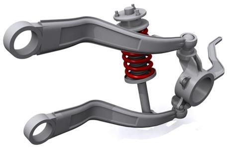
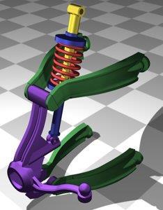
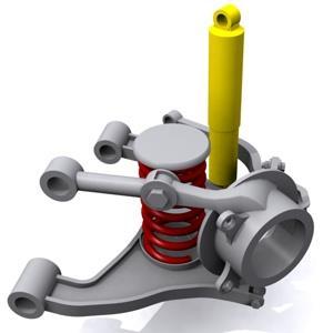
37 Short Long Arm (SLA) Front Suspension Gillespie Fig 7.5 A arm suspension 37


38 Short Long Arm (SLA) Front Suspension The most common lay out in many passenger cars after WWII Two triangular arms maintain the geometry of the wheels The upper and lower arms have generally different lengths so the name of short long arm suspension The arms are generally named A-arm or H-arm (USA), wishbones (GB), suspension triangles (en français) Variants or equivalent designs: The upper arms is replaced by a simple unique link The lower arms is substituted by a lateral arm and an angle strut 38
39 Short Long Arm (SLA) Front Suspension The SLA suspensions are well adapted to Vehicles with a longitudinal engine at the front and rear drive wheel Vehicles with a pseudo chassis separated for the sake of easiness of assembly and for the load shock absorption 39
40 Short Long Arm (SLA) Front Suspension Heisler Fig 7.34 : Effect of short long arms on the minimization of the wheel track 40

41 Short Long Arm (SLA) Front Suspension The design of the geometry calls for great care to reach high performances The geometry of the arms (hinge position) can improve the camber of the outer wheel by counteracting the wheel camber due to roll at the price of a higher camber on the inner wheel Taking unequal arms is attenuating the unfavorable conditions on the inner wheel, even though deteriorating the compensation on the outer wheel It is necessary to minimize the contact patch modifications during wheel travel 41

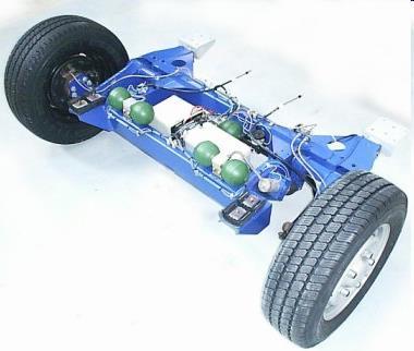
42 Short Long Arm (SLA) Suspension Double triangle suspensions mounted on a false chassis 42
 Suspension")

43 Short Long Arm (SLA) Suspension Porsche 993 (rear rolling train) 43
44 Mac Pherson suspension Gillespie Fig. 7.6 Mc Pherson strut suspension 44

45 Mac Pherson suspension Mc Pherson developed a suspension geometry similar to SLA suspension using a telescopic strut The strut is a prismatic joint integrated with the shock absorber The wheel is rigidly attached on the lower end of the strut so the prismatic joint maintains the wheel in a predefined camber geometry The lower part of the strut takes over the lateral and longitudinal forces generated in the wheel contact patch because of the rigid connections with the wheel knuckle In its upper lower part, the strut is connected to the car body using a spherical joint 45


46 Mac Pherson suspension Examples: Fiat Croma, Lancia Thema, Saab 9000, Fiat Tipo, Tempra, Lancia Delta, Dedra 46

47 Suspension Mac Pherson Système Mc Pherson original Système combinant l'amortisseur, le ressort et la fusée Le système fait office de fusée. La barre stabilisatrice sert au guidage Le combiné est fixé en bas au porte moyeu, et en haut directement sur le châssis. 47

48 Suspension Pseudo Mac Pherson La fusée (5) est solidarisée au corps du Mc Pherson Le bras inférieur (2) est triangulaire et reprend les forces longitudinales Avec un seul triangle, pas de contrôle fin du carrossage dynamique. Par contre, la présence de ce triangle inférieur permet de passer des puissances assez importantes. Utilisé généralement sur des propulsions de moyenne gamme, et presque toujours sur le train avant des tractions. 48
49 Mac Pherson suspension ADVANTAGES - DRAWBACKS (+) The Mac Pherson system is extremely compact. It allows the lateral engine mountings in the front axles. It is usually used in front drive vehicle (+) Because of the large separation of the connection points in the car body, it is well adapted to semi monocoque car body structures, even though the higher connection of the strut is a highly stressed zone. (+) The strut has the advantage of introducing a small number of parts (-) The strut geometry requires a high volume under the hood, which strongly limits the reduction of the height of the front car 49

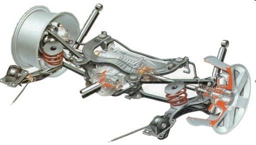
50 Multi (five)-link suspension Miliken Fig 7.33: Five link suspension of a Mercedes 50
51 Multi-link suspension 51
52 Rear multi-link suspension Recently, the multi-link suspension (five links) were developed (e.g. Mercedes, Corvette after 1984) The idea is simple: using 5 links in order to create the five kinematic constraints to define a suspension mechanism able to achieve a desired wheel path The links are connected through spherical joints, which transmit no torque and moment The whole wheel carrier is rotating during the wheel steering Generally one can see this approach as a separation of upper and lower A arms This approach provides a high flexibility to design the suspension characteristics 52
53 Rear multi-link suspension Miliken Fig 7.34: Five link suspension of the Corvette 53
54 Rear multi-link suspension The position and the orientation of the links proceeds from the same idea as for 3 links and 1 triangle (1 triangle = 2 links) Great flexibility of the kinematic approach: tailoring the instantaneous center of rotation in the different projection planes Aim: to achieve the desired kinematic performances in the frontal plane without any compromise with the kinematic in the lateral plane Other targets : to realize very short knuckle axes and very small scrubbing radius 54

55 Rear multi-link suspension 55

56 Rear trailing arm suspensions Gillespie Fig 7.8 : Rear trailing arm suspension of the corvette before
57 Rear trailing arm suspensions Milliken Fig 7.24 : Rear trailing suspension 57

58 Rear trailing arm suspensions 58
59 Rear trailing arm suspensions Often used on luxury cars in which performance is expected: e.g. rear suspension of the Corvette before 1984 The control arms absorb the longitudinal forces and the braking/acceleration torques. They also control the squat and dive motions The trailing arm suspension have the advantage to reduce the unsprung mass by mounting the differential on the chassis 59
60 Rear suspensions with semi trailing arms Gillespie Fig 7.9 : Rear semi trailing arm suspension 60
61 Rear suspensions with semi trailing arms Milliken Fig 7.25 : Rear semi trailing arm suspension 61
62 Rear suspensions with semi trailing arms The independent suspension with semi trailing arms were very popular on BMW and Mercedes The rotation axis makes generally an angle of about 25 with respect to the transverse direction of the car It gives rise to a wheel camber intermediate between trailing arms (no camber change with respect to the chassis) and swing axle The semi trailing arm generates steer effects with vertical motion (jounce and rebound) The combined effect steer / camber on the outer wheel is acting in an opposite direction to the turn direction, which generates a roll steer of the rear axle. Stiffness to the lateral force creates another steering effect that might become oversteering if uncontrolled 62

63 Rear suspensions with semi trailing arms 63
64 Swing axle suspensions Milliken Fig 7.26 : Rear swing axle suspension 64
65 Swing axle suspensions In the Corvette before 1984, a half shaft with a universal joint is used as the upper control arm while a strut is used as the lower lateral arm Milliken Fig 7.27 : Swing axle rear suspension (Corvette before 1984) 65

66 Swing axle suspensions The simplest way to make a rear suspension is to use swing suspension arm. The wheel is attached to an arm connected to the differential by a Universal joint. Famous example: the VW beetle It can be seen as a limit case of semi trailing arm The camber behavior is entirely determined by the rotation of the arm about its joint Because of the short radius circular motion the camber changes can be very important. Thus it is difficult to have a good performance in turn with swing axles 66
67 Swing axle suspensions Gillespie Fig 7.10 : Rear swing axle suspension: jacking 67
68 Swing axle suspensions The jacking problem, which is present in every independent suspension, is critical with swing axles Occurs in turn when the wheels develop important lateral forces and when the outer wheel is the most loaded. The lateral forces pointing inward wrt the chassis tends to lift the vehicle the body is lift up and its resistance to roll over decreases Reduction of the cornering stiffness due to the high camber thrust in the opposite direction to side slip forces Can lead to roll over or jack knife Jacking can be attenuated by including an extra arm to limit the wheel motion 68

69 Swing axle suspensions Jacking phenomenon in which the rear axles is pushed upward by the lateral forces developed at the contact patch Swing arm was applied in many small cars after WWII, especially British car as the Triumph and the Spitfire ones mbrvu 69
70 Rear swing axle suspensions ADVANTAGES DRAWBACKS (+) Low cost (-) Quite limited options to set-up the kinematics (-) Jacking of the rear axle lift by lateral forces in turn (-) Link between vertical motion and generation a high positive camber 70
Suspension systems and components
 Suspension systems and components 2of 42 Objectives To provide good ride and handling performance vertical compliance providing chassis isolation ensuring that the wheels follow the road profile very little
Vehicle dynamics Suspension effects on cornering
 Vehicle dynamics Suspension effects on cornering Pierre Duysinx LTAS Automotive Engineering University of Liege Academic Year 2013-2014 1 Bibliography T. Gillespie. «Fundamentals of vehicle Dynamics»,
Design and Analysis of suspension system components
 Design and Analysis of suspension system components Manohar Gade 1, Rayees Shaikh 2, Deepak Bijamwar 3, Shubham Jambale 4, Vikram Kulkarni 5 1 Student, Department of Mechanical Engineering, D Y Patil college
STUDY OF ROLL CENTER SAURABH SINGH *, SAGAR SAHU ** ABSTRACT
 STUDY OF ROLL CENTER SAURABH SINGH *, SAGAR SAHU ** *, ** Mechanical engineering, NIT B ABSTRACT As our solar car aims to bring new green technology to cope up with the greatest challenge of modern era
MECA0063 : Braking systems
 MECA0063 : Braking systems Pierre Duysinx Research Center in Sustainable Automotive Technologies of University of Liege Academic Year 2018-2019 1 Bibliography T. Gillespie. «Fundamentals of vehicle Dynamics»,
Vehicle Performance. Pierre Duysinx. Research Center in Sustainable Automotive Technologies of University of Liege Academic Year
 Vehicle Performance Pierre Duysinx Research Center in Sustainable Automotive Technologies of University of Liege Academic Year 2018-2019 1 Lesson 3: Tractive forces 2 Outline POWER AND TRACTIVE FORCE AT
Design, Modelling & Analysis of Double Wishbone Suspension System
 Design, Modelling & Analysis of Double Wishbone Suspension System 1 Nikita Gawai, 2 Deepak Yadav, 3 Shweta Chavan, 4 Apoorva Lele, 5 Shreyash Dalvi Thakur College of Engineering & Technology, Kandivali
KINEMATICS OF REAR SUSPENSION SYSTEM FOR A BAJA ALL-TERRAIN VEHICLE.
 International Journal of Mechanical Engineering and Technology (IJMET) Volume 8, Issue 8, August 2017, pp. 164 171, Article ID: IJMET_08_08_019 Available online at http://www.iaeme.com/ijmet/issues.asp?jtype=ijmet&vtype=8&itype=8
Design, analysis and mounting implementation of lateral leaf spring in double wishbone suspension system
 Design, analysis and mounting implementation of lateral leaf spring in double wishbone suspension system Rahul D. Sawant 1, Gaurav S. Jape 2, Pratap D. Jambhulkar 3 ABSTRACT Suspension system of an All-TerrainVehicle
Designing and Hard Point Optimization of Suspension System of a Three-Wheel Hybrid Vehicle
 ISSN (O): 2393-8609 International Journal of Aerospace and Mechanical Engineering Designing and Hard Point Optimization of Suspension System of a Three-Wheel Hybrid Vehicle Gomish Chawla B.Tech Automotive
MECA0063 : Driveline systems Part 3: Differentials
 MECA0063 : Driveline systems Part 3: Differentials Pierre Duysinx Research Center in Sustainable Automotive Technologies of University of Liege Academic Year 2018-2019 1 Bibliography T. Gillespie. «Fundamentals
A traditional semi-elliptical Hotchkiss leaf spring arrangement. On the left, the spring is connected to the frame through a shackle.
 Leaf spring From Wikipedia, the free encyclopedia This article does not cite any references or sources. Please help improve this article by adding citations to reliable sources. Unsourced material may
Torque steer effects resulting from tyre aligning torque Effect of kinematics and elastokinematics
 P refa c e Tyres of suspension and drive 1.1 General characteristics of wheel suspensions 1.2 Independent wheel suspensions- general 1.2.1 Requirements 1.2.2 Double wishbone suspensions 1.2.3 McPherson
SUMMARY OF STANDARD K&C TESTS AND REPORTED RESULTS
 Description of K&C Tests SUMMARY OF STANDARD K&C TESTS AND REPORTED RESULTS The Morse Measurements K&C test facility is the first of its kind to be independently operated and made publicly available in
II YEAR AUTOMOBILE ENGINEERING AT AUTOMOTIVE CHASSIS QUESTION BANK UNIT I - LAYOUT, FRAME, FRONT AXLE AND STEERING SYSTEM
 II YEAR AUTOMOBILE ENGINEERING AT 6402 - AUTOMOTIVE CHASSIS QUESTION BANK UNIT I - LAYOUT, FRAME, FRONT AXLE AND STEERING SYSTEM 1. Write about the requirements of frame and selection of cross section
Collegiate Design Series Suspension 101. Steve Lyman Formula SAE Lead Design Judge DaimlerChrysler Corporation
 Collegiate Design Series Suspension 101 Steve Lyman Formula SAE Lead Design Judge DaimlerChrysler Corporation There Are Many Solutions It depends. Everything is a compromise. Suspension 101 Ride Frequency/
Kinematic Analysis of Roll Motion for a Strut/SLA Suspension System Yung Chang Chen, Po Yi Tsai, I An Lai
 Kinematic Analysis of Roll Motion for a Strut/SLA Suspension System Yung Chang Chen, Po Yi Tsai, I An Lai Abstract The roll center is one of the key parameters for designing a suspension. Several driving
A double-wishbone type suspension is used in the front. A multi-link type suspension is used in the rear. Tread* mm (in.) 1560 (61.
 1560 (61.") CHASSIS SUSPENSION AND AXLE CH-69 SUSPENSION AND AXLE SUSPENSION 1. General A double-wishbone type suspension is used in the front. A multi-link type suspension is used in the rear. 08D0CH111Z Specifications
CHASSIS SUSPENSION AND AXLE CH-69 SUSPENSION AND AXLE SUSPENSION 1. General A double-wishbone type suspension is used in the front. A multi-link type suspension is used in the rear. 08D0CH111Z Specifications
1. SPECIFICATIONS 2. WHEEL ALIGNMENT Front Suspension. (gas type) Rear Suspension. (gas type)
 Rear Suspension. (gas type)") 441101 053 1. SPECIFICATIONS Front Suspension Rear Suspension Description Suspension type Spring type Shock absorber type Stabilizer bar type Suspension type Spring type Shock absorber type Stabilizer
441101 053 1. SPECIFICATIONS Front Suspension Rear Suspension Description Suspension type Spring type Shock absorber type Stabilizer bar type Suspension type Spring type Shock absorber type Stabilizer
Fundamentals of Steering Systems ME5670
 Fundamentals of Steering Systems ME5670 Class timing Monday: 14:30 Hrs 16:00 Hrs Thursday: 16:30 Hrs 17:30 Hrs Lecture 3 Thomas Gillespie, Fundamentals of Vehicle Dynamics, SAE, 1992. http://www.me.utexas.edu/~longoria/vsdc/clog.html
MECA0494 : Braking systems
 MECA0494 : Braking systems Pierre Duysinx Research Center in Sustainable Automotive Technologies of University of Liege Academic Year 2017-2018 1 MECA0494 Driveline and Braking Systems Monday 23/10 (@ULG)
1. SPECIFICATIONS 2. WHEEL ALIGNMENT
 441101 083 1. SPECIFICATIONS Front Suspension Rear Suspension Description Suspension type Spring type Shock absorber type Stabilizer bar type Suspension type Spring type Shock absorber type Stabilizer
MECA0492 : Vehicle dynamics
 MECA0492 : Vehicle dynamics Pierre Duysinx Research Center in Sustainable Automotive Technologies of University of Liege Academic Year 2017-2018 1 Bibliography T. Gillespie. «Fundamentals of vehicle Dynamics»,
Design of Suspension and Steering system for an All-Terrain Vehicle and their Interdependence
 Design of Suspension and Steering system for an All-Terrain Vehicle and their Interdependence Saurabh Wanganekar 1, Chinmay Sapkale 2, Priyanka Chothe 3, Reshma Rohakale 4,Samadhan Bhosale 5 1 Student,Department
Analysis and control of vehicle steering wheel angular vibrations
 Analysis and control of vehicle steering wheel angular vibrations T. LANDREAU - V. GILLET Auto Chassis International Chassis Engineering Department Summary : The steering wheel vibration is analyzed through
Compliant Mechanism Suspensions
 Brigham Young University BYU ScholarsArchive All Theses and Dissertations 2006-06-02 Compliant Mechanism Suspensions Timothy Melvin Allred Brigham Young University - Provo Follow this and additional works
August 2001 THINGS THAT MAKE SPRING CHANGES WORK BACKWARDS
 August 2001 WELCOME Mark Ortiz Automotive is a chassis consulting service primarily serving oval track and road racers. This newsletter is a free service intended to benefit racers and enthusiasts by offering
Study on Dynamic Behaviour of Wishbone Suspension System
 IOP Conference Series: Materials Science and Engineering Study on Dynamic Behaviour of Wishbone Suspension System To cite this article: M Kamal and M M Rahman 2012 IOP Conf. Ser.: Mater. Sci. Eng. 36 012019
SPMM OUTLINE SPECIFICATION - SP20016 issue 2 WHAT IS THE SPMM 5000?
 SPMM 5000 OUTLINE SPECIFICATION - SP20016 issue 2 WHAT IS THE SPMM 5000? The Suspension Parameter Measuring Machine (SPMM) is designed to measure the quasi-static suspension characteristics that are important
International Journal of Scientific & Engineering Research Volume 8, Issue 10, October-2017 ISSN
 309 Design and Analysis of Suspension System for a Formula Style Car Anshul Kunwar 1, Mohit Nagpal 2, Geetanjali Raghav 3 1 Student, Department of Mechanical Engineering, DIT University, Dehradun-248009
According to Newton's First Law, a moving body will continue moving in a straight line until it is acted
 RIDE CONTROL DEFINED According to Newton's First Law, a moving body will continue moving in a straight line until it is acted upon by another force. Newton's Second Law states that for each action there
Appendix X New Features in v2.4 B
 Appendix X New Features in v2.4 B Version 2.4B adds several features, which we have grouped into these categories: New Suspension Types or Options The program now allows for solid front axles and for several
Assemblies for Parallel Kinematics. Frank Dürschmied. INA reprint from Werkstatt und Betrieb Vol. No. 5, May 1999 Carl Hanser Verlag, München
 Assemblies for Parallel Kinematics Frank Dürschmied INA reprint from Werkstatt und Betrieb Vol. No. 5, May 1999 Carl Hanser Verlag, München Assemblies for Parallel Kinematics Frank Dürschmied Joints and
Design and Integration of Suspension, Brake and Steering Systems for a Formula SAE Race Car
 Design and Integration of Suspension, Brake and Steering Systems for a Formula SAE Race Car Mark Holveck 01, Rodolphe Poussot 00, Harris Yong 00 Final Report May 5, 2000 MAE 340/440 Advisor: Prof. S. Bogdonoff
9 Locomotive Compensation
 Part 3 Section 9 Locomotive Compensation August 2008 9 Locomotive Compensation Introduction Traditionally, model locomotives have been built with a rigid chassis. Some builders looking for more realism
Basic Wheel Alignment Techniques
 Basic Wheel Alignment Techniques MASTERING THE BASICS: Modern steering and suspension systems are great examples of solid geometry at work. Wheel alignment integrates all the factors of steering and suspension
SPMM OUTLINE SPECIFICATION - SP20016 issue 2 WHAT IS THE SPMM 5000?
 SPMM 5000 OUTLINE SPECIFICATION - SP20016 issue 2 WHAT IS THE SPMM 5000? The Suspension Parameter Measuring Machine (SPMM) is designed to measure the quasi-static suspension characteristics that are important
Suspension Analyzer Full Vehicle Version
 Suspension Analyzer Full Vehicle Version Overview of Features The Full Vehicle version of Suspension Analyzer has several enhancements over the standard version, the most significant is analyzing various
Comparative study between double wish-bone and macpherson suspension system
 IOP Conference Series: Materials Science and Engineering PAPER OPEN ACCESS Comparative study between double wish-bone and macpherson suspension system To cite this article: Shoaib Khan et al 2017 IOP Conf.
ISO 8855 INTERNATIONAL STANDARD. Road vehicles Vehicle dynamics and road-holding ability Vocabulary
 INTERNATIONAL STANDARD ISO 8855 Second edition 2011-12-15 Road vehicles Vehicle dynamics and road-holding ability Vocabulary Véhicules routiers Dynamique des véhicules et tenue de route Vocabulaire Reference
Chassis Dynamics. BMW Technical Training. BMW of North America, LLC Technical Training ST1115 8/1/12. Reference Manual. The Ultimate Driving Machine
 Reference Manual BMW Technical Training www.bmwcenternet.com The Ultimate Driving Machine Chassis Dynamics BMW of North America, LLC Technical Training ST1115 8/1/12 Information Status: August 01, 2012
Technical elements for minimising of vibration effects in special vehicles
 Technical elements for minimising of vibration effects in special vehicles Tomasz Ostrowski 1, Paulina Nogowczyk 2, Rafał Burdzik 3, Łukasz Konieczny 4 1, 2 SZCZĘŚNIAK Pojazdy Specjalne Sp. z o.o., Bestwińska
WHY CHOOSE MOTOR TRIKE INDEPENDENT REAR SUSPENSION?
 WHY CHOOSE MOTOR TRIKE INDEPENDENT REAR SUSPENSION? WHY CHOOSE MOTOR TRIKE INDEPENDENT REAR SUSPENSION? NOT ALL INDEPENDENT REAR SUSPENSIONS (IRS) ARE CREATED EQUALLY. THIS IS WHY A BMW AND A HYUNDAI DON
MECA0492 : Introduction to Vehicle Stability Control
 MECA0492 : Introduction to Vehicle Staility Control Pierre Duysinx Research Center in Sustainale Automotive Technologies of University of Liege Academic Year 2017-2018 1 Biliography T. Gillespie. «Fundamentals
1 Summary PROPORTIONAL RESPONSE TECHNICAL SUMMARY. Contents
 HABIT WHITE PAPER PROPORTIONAL RESPONSE TECHNICAL SUMMARY Contents 1 Summary 1 2 Suspension for Mountain Bikes 2 3 Proportional Response 10 4 Experimental Validation of Suspension Response 12 5 Size Specific
10/29/2013. Chapter 9. Mechanisms with Lower Pairs. Dr. Mohammad Abuhiba, PE
 Chapter 9 Mechanisms with Lower Pairs 1 2 9.1. Introduction When the two elements of a pair have a surface contact and a relative motion takes place, the surface of one element slides over the surface
Vehicle Engineering MVE 420 (2015)
") 1 Copyright Vehicle Engineering MVE 420 (2015) OVERVIEW AND APPROACH The aim of the Vehicle Engineering 420 course is to establish a technical foundation for prospective vehicle engineers. Basic scientific
1 Copyright Vehicle Engineering MVE 420 (2015) OVERVIEW AND APPROACH The aim of the Vehicle Engineering 420 course is to establish a technical foundation for prospective vehicle engineers. Basic scientific
MODELING SUSPENSION DAMPER MODULES USING LS-DYNA
 MODELING SUSPENSION DAMPER MODULES USING LS-DYNA Jason J. Tao Delphi Automotive Systems Energy & Chassis Systems Division 435 Cincinnati Street Dayton, OH 4548 Telephone: (937) 455-6298 E-mail: Jason.J.Tao@Delphiauto.com
Technician Handbook. 453 Suspension, Steering and Handling. Technician Objectives
 Technician Objectives 1. List the six functions of suspension components.. 2. List the six major groups of components that require inspection. 3. Explain the inspection methods for the individual suspension
epsilon Structural Design of Body and Battery Housing
 ALIVE, ENLIGHT & epsilon Final Workshop epsilon Structural Design of Body and Battery Housing Aachen, 22 September 2016 Dipl.-Ing. Johannes Stein Institute for Automotive Engineering Johannes Stein / Final
Design Methodology of Steering System for All-Terrain Vehicles
 Design Methodology of Steering System for All-Terrain Vehicles Dr. V.K. Saini*, Prof. Sunil Kumar Amit Kumar Shakya #1, Harshit Mishra #2 *Head of Dep t of Mechanical Engineering, IMS Engineering College,
SECTION 2C FRONT SUSPENSION TABLE OF CONTENTS
 SECTION 2C FRONT SUSPENSION TABLE OF CONTENTS Description and Operation... 2C-2 Front Suspension... 2C-2 Specifications... 2C-4 Component Locator... 2C-5 Front Suspension Assembly... 2C-5 Cross-Sectional
NEW DESIGN AND DEVELELOPMENT OF ESKIG MOTORCYCLE
 NEW DESIGN AND DEVELELOPMENT OF ESKIG MOTORCYCLE Eskinder Girma PG Student Department of Automobile Engineering, M.I.T Campus, Anna University, Chennai-44, India. Email: eskindergrm@gmail.com Mobile no:7299391869
R10 Set No: 1 ''' ' '' '' '' Code No: R31033
 R10 Set No: 1 III B.Tech. I Semester Regular and Supplementary Examinations, December - 2013 DYNAMICS OF MACHINERY (Common to Mechanical Engineering and Automobile Engineering) Time: 3 Hours Max Marks:
Introduction. Kinematics and Dynamics of Machines. Involute profile. 7. Gears
 Introduction The kinematic function of gears is to transfer rotational motion from one shaft to another Kinematics and Dynamics of Machines 7. Gears Since these shafts may be parallel, perpendicular, or
Dynamic Analysis of Double Wishbone and Double Wishbone with S Link + Toe Link
 RESEARCH ARTICLE OPEN ACCESS Dynamic Analysis of Double Wishbone and Double Wishbone with S Link + Toe Link Rajkumar Kewat, Anil Kumar Kundu,Kuldeep Kumar,Rohit Lather, Mohit Tomar RJIT, B.S.F ACADEMY
Determination of anti pitch geometry. acceleration [1/3]
![Determination of anti pitch geometry. acceleration [1/3]](/thumbs/83/87345496.jpg "Determination of anti pitch geometry. acceleration [1/3]") 1of 39 Determination of anti pitch geometry Similar to anti squat Opposite direction of D Alembert s forces. acceleration [1/3] Front wheel forces and effective pivot locations 2of 39 Determination of
1of 39 Determination of anti pitch geometry Similar to anti squat Opposite direction of D Alembert s forces. acceleration [1/3] Front wheel forces and effective pivot locations 2of 39 Determination of
Design and optimization of Double wishbone suspension system for ATVs
 Design and optimization of Double wishbone suspension system for ATVs Shantanu Garud 1, Pritam Nagare 2, Rohit Kusalkar 3, Vijaysingh Gadhave 4, Ajinkya Sawant 5 1,2,3,4Dept of Mechanical Engineering,
Load cells for a Portable Structure
 Load cells for a Portable Structure Load Restoring force Side force We know that a weighing system must be rigid to get good results. We should also know that a three point system is inherently more stable
iracing.com Williams-Toyota FW31 Quick Car Setup Guide
 iracing.com Williams-Toyota FW31 Quick Car Setup Guide In this guide we will briefly explain a number of key setup parameters which are distinct to the FW31 and which are new to iracing vehicles. We hope
SRI VIDYA COLLEGE OF ENGINEERING & TECHNOLOGY DEPARTMENT OF MECHANICAL ENGINEERING. ME AUTOMOBILE ENGINEERING Question Bank
 SRI VIDYA COLLEGE OF ENGINEERING & TECHNOLOGY DEPARTMENT OF MECHANICAL ENGINEERING ME6602 - AUTOMOBILE ENGINEERING Question Bank UNIT-4 - STEERING, BREAKS AND SUSPENSION PART-A 1. Define wheel track and
Participant 's Manual Basic principles Chassis
 Participant 's Manual Basic principles Chassis BMW Service Aftersales Training conceptinfo@bmw.de 2004 BMW Group München, Germany. Reprints of this manual or its parts require the written approval of BMW
NVH CAE concept modeling and optimization at BMW.
 06.06.2011 Page 1 VECOM Suppliers Workshop: Vehicle Concept Modeling in the Automotive Sector. NVH CAE concept modeling and optimization at BMW. 06.06.2011 VLEVA, Brussels Page 2 NVH CAE concept modeling
The Mark Ortiz Automotive
 July 2004 WELCOME Mark Ortiz Automotive is a chassis consulting service primarily serving oval track and road racers. This newsletter is a free service intended to benefit racers and enthusiasts by offering
DESIGN AND ANALYSIS OF PUSH ROD ROCKER ARM SUSPENSION USING MONO SPRING
 Volume 114 No. 9 2017, 465-475 ISSN: 1311-8080 (printed version); ISSN: 1314-3395 (on-line version) url: http://www.ijpam.eu ijpam.eu DESIGN AND ANALYSIS OF PUSH ROD ROCKER ARM SUSPENSION USING MONO SPRING
Chapter. Suspension System Technology. Basic Suspension System. Functions of a Suspension System
 76 Chapter Suspension System Technology Name Instructor Date Score Objective: After studying this chapter, you will be able to explain the construction and operation of modern suspension systems. Basic
Modern Auto Tech Study Guide Chapter 67 & 69 Pages Suspension & Steering 32 Points. Automotive Service
 Modern Auto Tech Study Guide Chapter 67 & 69 Pages 1280 1346 Suspension & Steering 32 Points Automotive Service 1. The system allows a vehicle s tires & wheels to move up and down as they roll. Steering
Ball splines can be configured for an endless number of automated operations. Demystifying Ball Spline Specs
 Ball splines can be configured for an endless number of automated operations. Demystifying Ball Spline Specs Place a recirculating-ball bushing on a shaft and what do you get? Frictionless movement of
Finite Element Analysis of Anti-Roll Bar to Optimize the Stiffness of the Anti-Roll Bar and the Body Roll
 International OPEN ACCESS Journal Of Modern Engineering Research (IJMER) Finite Element Analysis of Anti-Roll Bar to Optimize the Stiffness of the Anti-Roll Bar and the Body Roll Bankar Harshal 1, Kharade
Design of a rear suspension configuration for a live axle race car to achieve optimum handling characteristics.
 University of Southern Queensland Faculty of Engineering and Surveying Design of a rear suspension configuration for a live axle race car to achieve optimum handling characteristics. A dissertation submitted
Design of Formula SAE Suspension
 SAE TECHNICAL PAPER SERIES 2002-01-3310 Design of Formula SAE Suspension Badih A. Jawad and Jason Baumann Lawrence Technological University Reprinted From: Proceedings of the 2002 SAE Motorsports Engineering
Chassis and Suspension Concepts
 Chassis and Suspension Concepts Chassis and suspension concepts for ULSAB-AVC feature a range of high strength steels and new technologies such as TWBs for wishbones and tailor tube hydroforming. 7.1 BACKGROUND
Study of the Performance of a Driver-vehicle System for Changing the Steering Characteristics of a Vehicle
 20 Special Issue Estimation and Control of Vehicle Dynamics for Active Safety Research Report Study of the Performance of a Driver-vehicle System for Changing the Steering Characteristics of a Vehicle
Tire 16 inch 225/75R inch 255/60R 18
 417009 143 1. SPECIFICATIONS Description Specification Tire 16 inch 225/75R 16 Tire inflation pressure 18 inch 255/60R 18 Front: 32 psi Rear: 32 psi (44 psi: when the vehicle is fully laden with luggage)
Railway Technical Web Pages
 Railway Technical Web Pages Archive Page Vehicle Suspension Systems Introduction Almost all railway vehicles use bogies (trucks in US parlance) to carry and guide the body along the track. Bogie suspension
OPERATING AND MAINTENANCE MANUAL
 MAN32 15/4/21 1 of 38 SELF-STEERING AXLE OPERATING AND MAINTENANCE MANUAL MAN32 15/4/21 2 of 38 Contents of the manual SECTION 1 INTRODUCTION TO SELF STEERING AXLE 1.1 Operating principle 1.2 Basic components
Shock Absorbers What is Ride Control Vehicle Dynamics Suspension System Shock Absorbers Struts Terminology
 Home Tech Support Shock Absorbers Shock Absorbers What is Ride Control Vehicle Dynamics Suspension System Shock Absorbers Struts Terminology A BRIEF HISTORY These first shock absorbers were simply two
Skid against Curb simulation using Abaqus/Explicit
 Visit the SIMULIA Resource Center for more customer examples. Skid against Curb simulation using Abaqus/Explicit Dipl.-Ing. A. Lepold (FORD), Dipl.-Ing. T. Kroschwald (TECOSIM) Abstract: Skid a full vehicle
1. Rear Suspension (Multi-link Type)
") (MULTI-LINK TYPE) 1. Rear Suspension (Multi-link Type) A: GENERAL The rear suspension is a multilink type. The suspension on each side consists of a rear arm, front link, upper link, rear link, sub frame
(MULTI-LINK TYPE) 1. Rear Suspension (Multi-link Type) A: GENERAL The rear suspension is a multilink type. The suspension on each side consists of a rear arm, front link, upper link, rear link, sub frame
164 6 Vehicle Transmission Systems: Basic Design Principles
 164 6 Vehicle Transmission Systems: Basic Design Principles Table 6.10. (continued) 6.25b 7 AMT, 2-stage S Getrag 247 12.15 12.16 10/ 6.26 6 DCT, principle FT VW DSG 12.17 12.20 11/ 6.27 7 DCT S ZF 7 DCT
Optimization of vehicle handling performance by increasing the ARB effectiveness. Date :- 22 June 2010
 Optimization of vehicle handling performance by increasing the ARB effectiveness Date :- 22 June 2010 BY Dr. A K Jindal, M.G. Belsare and T. M. Arun Prakash 1 Contents Vehicle Specifications Suspension
MECA0063 : Driveline systems
 MECA0063 : Driveline systems Pierre Duysinx Research Center in Sustainable Automotive Technologies of University of Liege Academic Year 2018-2019 1 Bibliography T. Gillespie. «Fundamentals of vehicle Dynamics»,
A new approach to steady state state and quasi steady steady state vehicle handling analysis
 Vehicle Dynamics Expo June 16 nd -18 th 2009 A new approach to steady state state and quasi steady steady state vehicle handling analysis Presentation By Claude Rouelle OptimumG Overview Vehicle Dynamics
Strategy for Transfer Elemental Designing and Employing Physical Characteristic Modeling of Steering Maneuvering (the Second Report)
") TECHNICAL PAPER Strategy for Transfer Elemental Designing and Employing Physical Characteristic Modeling of Steering Maneuvering (the Second Report) S. KIMURA S. NAKANO Our previous report introduced a
TECHNICAL PAPER Strategy for Transfer Elemental Designing and Employing Physical Characteristic Modeling of Steering Maneuvering (the Second Report) S. KIMURA S. NAKANO Our previous report introduced a
DRIVING STABILITY OF A VEHICLE WITH HIGH CENTRE OF GRAVITY DURING ROAD TESTS ON A CIRCULAR PATH AND SINGLE LANE-CHANGE
 Journal of KONES Powertrain and Transport, Vol. 1, No. 1 9 DRIVING STABILITY OF A VEHICLE WITH HIGH CENTRE OF GRAVITY DURING ROAD TESTS ON A CIRCULAR PATH AND SINGLE LANE-CHANGE Kazimierz M. Romaniszyn
DEGREE PROJECT 2004: M037
 DEGREE PROJECT 2004: M037 Department of Technology, Mathematics and Computer Science Concept Development of a Single Wishbone Independent Rear Suspension Matthijs Klomp Anders Nygren Concept Development
SIX-BAR STEERING MECHANISM
 SIX-BAR STEERING MECHANISM Shrey Lende 1 1 UG Student, Department of Mech, G.H Raisoni College of Engineering, Nagpur, RTMN University ABSTRACT In this paper a steering system is designed for a Low weight
VEHICLE ANTI-ROLL BAR ANALYZED USING FEA TOOL ANSYS
 VEHICLE ANTI-ROLL BAR ANALYZED USING FEA TOOL ANSYS P. M. Bora 1, Dr. P. K. Sharma 2 1 M. Tech. Student,NIIST, Bhopal(India) 2 Professor & HOD,NIIST, Bhopal(India) ABSTRACT The aim of this paper is to
SAE Mini BAJA: Suspension and Steering
 SAE Mini BAJA: Suspension and Steering By Zane Cross, Kyle Egan, Nick Garry, Trevor Hochhaus Team 11 Progress Report Submitted towards partial fulfillment of the requirements for Mechanical Engineering
Wheel Alignment Fundamentals
 CHAPTER 67 Wheel Alignment Fundamentals OBJECTIVES Upon completion of this chapter, you should be able to: Describe each wheel alignment angle. Tell which alignment angles cause wear or pull. KEY TERMS
Vehicle Dynamic Simulation Using A Non-Linear Finite Element Simulation Program (LS-DYNA)
") Vehicle Dynamic Simulation Using A Non-Linear Finite Element Simulation Program (LS-DYNA) G. S. Choi and H. K. Min Kia Motors Technical Center 3-61 INTRODUCTION The reason manufacturers invest their time
Vehicle Dynamic Simulation Using A Non-Linear Finite Element Simulation Program (LS-DYNA) G. S. Choi and H. K. Min Kia Motors Technical Center 3-61 INTRODUCTION The reason manufacturers invest their time
White Paper: The Physics of Braking Systems
 White Paper: The Physics of Braking Systems The Conservation of Energy The braking system exists to convert the energy of a vehicle in motion into thermal energy, more commonly referred to as heat. From
Jim Kasprzak 36 years racing experience Developed 7-post testing for GM Racing Currently Race Engineer for SRT Viper Expertise includes:
 Jim Kasprzak 36 years racing experience Developed 7-post testing for GM Racing Currently Race Engineer for SRT Viper Expertise includes: Race Engineering 7 post testing Suspension Engineering Shock design,
Technical Report Lotus Elan Rear Suspension The Effect of Halfshaft Rubber Couplings. T. L. Duell. Prepared for The Elan Factory.
 Technical Report - 9 Lotus Elan Rear Suspension The Effect of Halfshaft Rubber Couplings by T. L. Duell Prepared for The Elan Factory May 24 Terry Duell consulting 19 Rylandes Drive, Gladstone Park Victoria
Silencers. Transmission and Insertion Loss
 Silencers Practical silencers are complex devices, which operate reducing pressure oscillations before they reach the atmosphere, producing the minimum possible loss of engine performance. However they
Wheeled Mobile Robots
 Wheeled Mobile Robots Most popular locomotion mechanism Highly efficient on hard and flat ground. Simple mechanical implementation Balancing is not usually a problem. Three wheels are sufficient to guarantee
DESIGN AND ANALYSIS OF LEAF SPRING FOR SOLAR VEHICLE
 DESIGN AND ANALYSIS OF LEAF SPRING FOR SOLAR VEHICLE MAY MYA DARLI CHO, HTAY HTAY WIN, 3 AUNG KO LATT,,3 Department of Mechanical Engineering, Mandalay Technological University, Mandalay, Myanmar E-mail:
THE INFLUENCE OF PHYSICAL CONDITIONS OF SUSPENSION RUBBER SILENT BLOCKS, IN VEHICLE HANDLING AND ROAD- HOLDING
 REGIONAL WORKSHOP TRANSPORT RESEARCH AND BUSINESS COOPERATION IN SEE 6-7 December 2010, Sofia THE INFLUENCE OF PHYSICAL CONDITIONS OF SUSPENSION RUBBER SILENT BLOCKS, IN VEHICLE HANDLING AND ROAD- HOLDING
STEERING SYSTEM Introduction
 STEERING SYSTEM Introduction The steering makes it possible to change direction. The steering must be reliable and safe; there must not be too much play in the steering. It must be possible to steer accurately.
III B.Tech I Semester Supplementary Examinations, May/June
 Set No. 1 III B.Tech I Semester Supplementary Examinations, May/June - 2015 1 a) Derive the expression for Gyroscopic Couple? b) A disc with radius of gyration of 60mm and a mass of 4kg is mounted centrally