Installation and Maintenance Manual. Medical Gas Outlet. British Standard Compatible
|
|
|
- Cody Griffin Baker
- 5 years ago
- Views:
Transcription


1 Installation and Maintenance Manual Medical Gas Outlet British Standard Compatible w w w. a m i c o. c o m
2 Table of Contents Product Description 3 Cleaning and Lubrication 3 Inspection and Testing 4 Installation & Dimensions 4-7 Flush Mount 5 Console Mount 6 Surface Mount 7 Service 8-12 Preventive Maintenance 8 Latch-Valve Assembly 9 AGSS Latch-Valve Assembly 10 AGSS Flow Control Adjustment 11 Rough-In Assembly-Flush, Console and Surface Mount 12 Model Numbers 13 Latch-Valve Assembly 13 Rough-in Assembly 13 Complete Outlets 13 Gas Indexing 14 Replacement Components Latch-Valve Assembly 15 AGSS Replacement Components 16 Rough-In 17 2 Amico Corporation
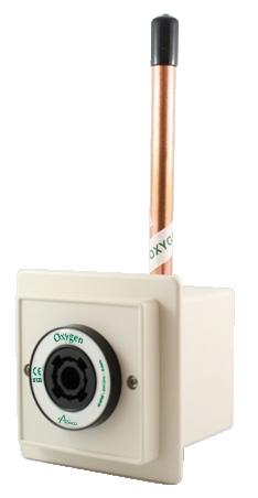
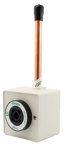
3 Product Description The Amico Medical Gas British Outlet is composed of two separated modules: the Rough-in Assembly and the Latch- Valve Assembly. The Rough-in Assembly consists of a brass machined body that incorporates a spring loaded check assembly. A 12.7 mm OD, 9.52 mm ID copper pipe is sliver brazed into the body for external pipeline connections. The brass body and pipe assembly are inserted into a gas specific plate. The Rough-in Assembly has a colour coded label on the front plate and the copper pipe, so that the installer can easily identify the gas that the copper pipe should be connected to. The Roughin Assembly incorporated a check valve that allows the Latch-Valve Assembly to be removed for service, without requiring the pipeline to be shut down. The Rough-in Assembly has a DUAL pin gas specific indexing arrangement to prevent the wrong Latch-Valve assembly from being plugged into the Rough-in Assembly (see page 17). The Latch-Valve Assembly is manufactured with a gas specific housing which accepts, retains and releases the probe, indexed on the back side to match gas specific indexing of the Rough-in Assembly. CAUTION: DO NOT over tighten the Latch-Valve mounting screws! Distortion of the Latch-Valve can occur. Outlets are available for oxygen, medical air, surgical air, nitrous oxide, medical vacuum and anesthetic gas scavenging system. These are designed in accordance with HTM and ISO Cleaning and Lubrication The Amico British Outlets are factory cleaned for oxygen service. Exposed surfaces of the Outlet may be cleaned with a mild detergent solution or wiped with a disinfectant commonly used in patient rooms, which is compatible with plastic. Lubricate elastomer seals sparingly with silicone lubricant that is oxygen compatible. DO NOT USE OIL 3
4 Inspection and Testing Pressure drops across the Amico British Outlet shall comply with ISO 9170 Standards. Terminal Unit Nominal Distribution Pressure (kpa) Test Pressure (kpa) Test Flow (1/min) Maximum Pressure Drop Across a Terminal Unit (kpa) 400 to to to 1, * Absolute pressure Vacuum * AGSS Requirements for flow and pressure drop across terminal units with probe inserted ISO 9170 Standards. Terminal Type Test Pressure Test Flow (1/min) Maximum Pressure Drop Across a Terminal Unit (kpa) 1 Atmospheric pressure Note: The Amico British Outlets meet and exceed the requirements at the time of manufacture. However piping source capacity, sizing and restrictions may prevent outlets form attaining these values. Installation and Dimensions The Amico British Outlet should be mounted at a height of between 900 mm and 1400 mm above finished floor level and not less than 200 mm from any obstruction. Where more than one Outlet unit is to be mounted in one location, these should be mounted at the following spacing; Two Outlet units mm centres Three or more Outlets units mm centres Outlet units mounted in a horizontal array shall be installed in the following sequence when viewed from the front, left to right; O₂; N₂O; 50%O₂/50%N₂O; Medical Air, Surgical Air, Vacuum; AGSS Please refer to HTM Amico Corporation
5 Installation and Dimensions Flush Mount Flush Mounted Terminal Unit 58mm 58mm 80mm 102mm 58mm 80mm 102mm 22mm 73mm 5
6 Installation and Dimensions Console Mount Console Mounted Terminal Unit 53mm 29mm 260mm 92mm 83mm 102mm 46mm 73mm 102mm 64mm 6 Amico Corporation
7 Installation and Dimensions Surface Mount Surface Mounted Terminal Unit 72mm 58mm 80mm 58mm 80mm 8mm 88mm 7
8 Preventative Maintenance Regular inspection and maintenance of the Outlets will prolong its life and reduce the possibility of sudden, inconvenient component failures. The use of damaged probes or faulty equipment may require further maintenance. Outlets should be subjected to regular inspection and testing as follows: Monthly; a. Visually inspect the Outlet for signs of damage. b. Check to see if the Front Latch Assembly (2nd Fix) operates smoothly with the gas specific probe. c. If there is any disagreement with the operation of the Front Latch Assembly (2nd Fix), remove the unit for closer inspection/repair/replacement if necessary. Annually; a. Remove Trim Plate and clean debris from the mounting box. b. Remove Front Latch Assembly (2nd fix) and inspect the barrel for any damage. c. Inspect the Rough-in Assembly (1st fix) for any damage. If damage or leaking replace components. d. Test Front Latch Assembly (2nd fix) for correct operation (connection and disconnection of the probe) using a blank probe. 8 Amico Corporation
9 Latch-Valve Assembly Unscrew the two Trim Plate screws (1), and remove Trim Box Plate (2) and the Trim plate (3). 2. Unscrew the two Retaining screws (5) until the Latch-Valve Assembly (4) can be removed from the Outlet. 3. Remove the two Retaining washer screws (11), and remove the Retaining washer (10). 4. Remove the gas connector (9) 5. Remove the Body Seal (6) and Poppet (7) from the front of the Gas Connector (9). Inspect the items for wear or damage and replace the Body Seal (6). 6. Remove the Gas or Vacuum Spring (8, to inspect if wear id damage. Re-install the Gas or Vacuum Spring. 7. Re-install all internal components into the Gas Connector (9). Check that the Gas or Vacuum Spring (8), Body Seal (6) and Poppet (7) are in place. Re-install the round Retaining washer (10) and secure with two Retaining washer screws (11), do not over tighten. 8. Re-install the Latch-Valve Assembly into the outlet. Coat the connector (9) with a thin coat of oxygen compatible silicone lubricant to aid insertion. Tighten down the Retaining screws (5), DO NOT over tighten, as this could damage the Latch-Valve Assembly. 9. Re-install Trim Plate (3) and Trim Box Plate (2) and tighten down Trim Plate screws (1). 10. Connect gas specific adapter into the outlet. The connection should be smooth and the adapter should lock and remain in place allowing gas to flow. If not, replace the entire Latch-Valve Assembly (4). 9
10 AGSS Latch-Valve Assembly Unscrew the two Trim Plate screws (1), and remove Trim Box Plate (2) and the Trim plate (3). 2. Unscrew the two Retaining screws (5) until the Latch-Valve Assembly (4) can be removed for the Outlet. 3. After removing the Latch-Valve Assembly (4) from the Outlet, you can then pull the Check Valve Body Assembly from the back side of the Latch-Valve Assembly (4). Remove the Check Valve Body Seal (10) and check for any abnormal wear or Damage and Replace, coat the O-Ring with a thin coat of oxygen compatible silicone lubricant. 4. Disassembly of the Check Valve Body Assembly: Hold the Check Valve Body Assembly in one hand, and push down the Check Valve (6) with your thumb of the same hand, compressing the Check Valve Spring (9). Remove the Check Valve O-Ring (12). Release the Check Valve (6) slowly; the Check Valve Body Assembly will fall apart. 5. Reassembly of the Check Valve Body Assembly: Re-install the Check Valve Spring (9) onto the Check Valve (6), and then insert them into the Check Valve Body (11). Again, hold the Check Valve Body Assembly in one hand, and push down the Check Valve (6) with your thumb of the same hand, compressing the Check Valve Spring (9). Before re-installing the Check Valve O-Ring (12), coat the O-Ring with a thin coat of oxygen compatible silicone lubricant. 6. Insert the Check Valve Body Assembly into the back of the Latch-Valve Assembly. 7. Re-install the Latch-Valve Assembly into the outlet. Coat the outer portion of the Check Valve Body Assembly with a thin coat of oxygen compatible silicone lubricant, to aid insertion. Tighten down Retaining Screws (5), DO NOT over tighten, as this could damage the Latch-Valve. 8. Re-install Trim Plate (3) and Trim Box Plate (2) and tighten down Trim Plate Screws (1). 9. Connect gas specific adapter into the outlet. The connection should thread in smooth and the adapter should remain in place allowing gas to flow. If not, replace the entire Latch-Valve Assembly (4). 10 Amico Corporation

11 AGSS Flow Control Adjustment Reference Part Numbers: O-BSQ-REC-AGS O-BSQ-CON-AGS O-BSQ-SUR-ARS A.G.S.S. Threaded Nose Valve Flow Control Screw (3mm Allen Key) Surface Mount Box British Standard A.G.S.S. 1. Insert a 3 mm Allen Key into the front of the Check Valve. 2. Adjust the Flow Control Screw to desired setting. 11
12 Rough-In Assembly CAUTION: Ensure that the supply pressure is shut off before performing service. Inside the Rough-in Assembly is a secondary check valve whose function is to shut off gas flow when the Latch-Valve Assembly is removed. This seat/seal also prevents leakage around the latch-valve connector. As the secondary seal is only a static seal, it will rarely need replacement. However, if the seat/seal does need replacement, follow the following procedure: NOTE: Suction inlets (Vacuum and AGSS) are not supplied with Secondary Check Valves. The Secondary Check Valve (4) and Secondary Check Valve Spring (5) are not required. 1. Ensure that no pressure exists in the line by depressing the secondary check (4). 2. Remove the retaining ring (1) from the inside of the outlet body. Use a small screwdriver to pull the end of the ring toward the center and then pull the ring up and out. 3. Remove the washer (2), seat/seal (3), secondary check valve (4) and the secondary check valve spring (5). Inspect items for wear or damage and replace the seat/seal (3). 4. Re-install the spring (5), secondary check valve (4), seat/seal (3) and the washer (2). Insert the retaining ring (1) into the slot and ensure that the whole ring is seated properly. 5. Turn on the pressure and check for leaks. Re-install the Latch-Valve Assembly and perform then inspection and test. 12 Amico Corporation
13 Model Numbers Flush Mounted Latch-Valve Assembly Rough-in Assembly Complete Assembly Oxygen O-FASC-BSQ-OXY O-BAKBSQ-OXY O-BSQ-REC-OXY Medical Air O-FASC-BSQ-AIR O-BAKBSQ-AIR O-BSQ-REC-AIR Surgical Air O-FASC-BSQ-SAI O-BAKBSQ-SAI O-BSQ-REC-SAI Vacuum O-FASC-BSQ-VAC O-BAKBSQ-VAC O-BSQ-REC-VAC Nitrous Oxide O-FASC-BSQ-N2O O-BAKBSQ-N2O O-BSQ-REC-N2O Anesthetic Gas Scavenging System O-FASC-BSQ-AGS O-BAKBSQ-AGS O-BSQ-REC-AGS Console Mounted Latch-Valve Assembly Rough-in Assembly Complete Assembly Oxygen O-FASC-BSQ-OXY O-BAKCON-BSQ-OXY O-BSQ-CON-OXY Medical Air O-FASC-BSQ-AIR O-BAKCON-BSQ-AIR O-BSQ-CON-AIR Surgical Air O-FASC-BSQ-SAI O-BAKCON-BSQ-SAI O-BSQ-CON-SAI Vacuum O-FASC-BSQ-VAC O-BAKCON-BSQ-VAC O-BSQ-CON-VAC Nitrous Oxide O-FASC-BSQ-N2O O-BAKCON-BSQ-N2O O-BSQ-CON-N2O Anesthetic Gas Scavenging System O-FASC-BSQ-AGS O-BAKCON-BSQ-AGS O-BSQ-CON-AGS Surface Mounted Latch-Valve Assembly Rough-in Assembly Complete Assembly Oxygen O-FASC-BSQ-OXY O-BAKBSQ-OXY O-BSQ-SUR-OXY Medical Air O-FASC-BSQ-AIR O-BAKBSQ-AIR O-BSQ-SUR-AIR Surgical Air O-FASC-BSQ-SAI O-BAKBSQ-SAI O-BSQ-SUR-SAI Vacuum O-FASC-BSQ-VAC O-BAKBSQ-VAC O-BSQ-SUR-VAC Nitrous Oxide O-FASC-BSQ-N2O O-BAKBSQ-N2O O-BSQ-SUR-N2O Anesthetic Gas Scavenging System O-FASC-BSQ-AGS O-BAKBSQ-AGS O-BSQ-SUR-AGS 13
14 Gas Indexing As seen from the front of the Rough-In Assemblies VACUUM OXYGEN NITROUS OXIDE MEDICAL AIR SURGICAL AIR AGSS 14 Amico Corporation
15 Replacement Components Latch-Valve Assembly Item Description Model Numbers 1 Trim Plate Screws (2 required) H-STPP-6150AB 2 Trim Box Plate O-X-BSQC-BOX625 3 Trim Plate O-X-BSQC-TRIM 4 British Standard Latch-Valve See Above 5 Outlet Mounting Screws (2 required) H-MPP-0616SS 6 Body Seal O-X-OXE-SEAT* 7 Poppet for Body O-X-BSQC-POPET* 8a Spring for All Gases (except Vac.) O-X-LVAPB-SPGAS* 8b Spring for Vacuum O-X-LVAPB-SPVAC* (only for Vacuum) 9 Gas Connector O-X-LVAPB-BDY 10 Retaining Washer O-X-BSQC-WASH 11 Retaining Washer Screws (2 required) H-HLTPP Above parts with an * are found in repair kit: O-RK-LVA-BSQ 15
16 Replacement Components AGSS Replacement Components Item Description Model Numbers 1 Trim Plate Screws (2 required) H-STPP-6150AB 2 Trim Box Plate O-X-BSQC-BOX625 3 Trim Plate O-X-BSQC-TRIM 4 British Standard Latch-Valve See Above 5 Outlet Mounting Screws (2 required) H-MPP-0616SS 6 AGSS Check Valve O-X-BSQC-CHKVLV 7 Flow Adjustment Screw H-HSSS-CPM601-6SS 8 Locking Screw H-HSSS-CPM601-6SS 9 AGSS Check Valve Spring O-X-BSQC-VLV-SPR* 10 Check Valve Body Seal H-ORING-020VTN* 11 Check Valve Body O-X-BSQC-LATCH 12 Check Valve O-Ring O-X-LVAQ-ORING* Above parts with an "*" are found in repair kit: O-RK-LVA-BSQ-AGS 16 Amico Corporation
17 Replacement Components Rough-in Assembly Item Description Model Numbers 1 Retaining Ring O-X-BAK-RETAI* 2 Washer H-WASH-895-SS* 3 Seat/Seal O-X-BAK-SEAT* 4 Secondary Check Valve O-X-BAK-CHECK* 5 Secondary Check Valve Spring O-X-BAK-SPRING* 6 Console Rough-in Assembly See Above 7 Flush and Surface Mount Rough-in Assembly See Above Note: Suction inlets (Vacuum and AGSS) are not supplied with Secondary Check Valves. The Secondary Check Valve (4) and Secondary Check Valve Spring (5) are not required. 17
18 Amico Corporation 85 Fulton Way, Richmond Hill Ontario, L4B 2N4, Canada Toll Free Tel: Toll Free Fax: Tel: Fax: Authorized Representative: RMS-UK Limited 28 Trinity Road Nailsea, Somerset BS484NU England Phone & Fax: APE-INSTAL-MANI-BRIT-STD-OUTLET
Installation and Maintenance Manual. Medical Gas Outlet. British Standard Slim Style Compatible
 Installation and Maintenance Manual Medical Gas Outlet British Standard Slim Style Compatible w w w. a m i c o. c o m Table of Contents Product Description 3 Cleaning and Lubrication 3 Inspection and Testing
PRECISION UK Ltd. Medical Gas Outlet BS Standard
 Contents Page Section No. Product Description General 1 First Fix Assembly 1.2 Check Valve Assembly 1.3 Second Fix Assembly 1.4 Operation General 2 Probe Connection/Disconnection 2.2 Safety General 3 Installation
FLEXIBLE PENDANTS with Axis MEDICAL GAS TERMINAL UNITS
 FLEXIBLE PENDANTS with Axis MEDICAL GAS TERMINAL UNITS Phoenix Pipeline Products Limited. Unit 8, McKenzie Industrial Park, Tel No.: 44 (0) 161 428 7200 Bird Hall Lane, Fax No.: 44 (0) 161 428 7010 Stockport,
Outlets and Accessories
 Service Manual Series B Quick-Connect and Diameter-Index Safety System Outlets and Accessories MAN0-03 Part No. 803-00 Rev. D Pg. Table of Contents General Product Description...3 Tools and Service Materials...
Axis MEDICAL GAS TERMINAL UNITS
 Axis MEDICAL GAS TERMINAL UNITS Phoenix Pipeline Products Limited. Unit 8, McKenzie Industrial Park, Tel No.: 44 (0) 161 428 7200 Bird Hall Lane, Fax No.: 44 (0) 161 428 7010 Stockport, Email: info@p3-phoenix.com
Axis AGSS TERMINAL UNITS
 Axis AGSS TERMINAL UNITS. Unit 8, McKenzie Industrial Park, Tel No.: 44 (0) 161 428 7200 Bird Hall Lane, Fax No.: 44 (0) 161 428 7010 Stockport, Email: info@p3-phoenix.com U.K., SK3 0SB www.p3-phoenix.com
RIGID PENDANT. Phoenix Pipeline Products Limited. Installation, Operation and Maintenance Manual
 RIGID PENDANT Phoenix Pipeline Products Limited. Unit 8, McKenzie Industrial Park, Tel No.: 44 (0) 161 428 7200 Bird Hall Lane, Fax No.: 44 (0) 161 428 7010 Stockport, Email: info@p3-phoenix.com U.K.,
Service Manual Gemini, Diamond II and Diamond III Medical Gas Outlets for Concealed Piping and Console Applications
 Service Manual Gemini, Diamond II and Diamond III Medical Gas Outlets for Concealed Piping and Console Applications MAN0-049 Part number 847706-00 Rev. C00 Table of Contents General Product Description...
Gemini, Diamond II and Diamond III Medical Gas Outlets for Concealed Piping and Console Applications
 Service Manual Gemini, Diamond II and Diamond III Medical Gas Outlets for Concealed Piping and Console Applications Andersen Medical Gas Place Lafitte Madisonville, LA 70447 http://www.themedicalgas.com
At Amico Labs we are dedicated to continued growth while producing products of outstanding quality, and providing excellent service.
 1 ABOUT US Amico Corporation is a leading manufacturer of Medical Equipment, selling its products through a global distribution channel from three manufacturing facilities in Canada and the U.S. With a
Pressure Switch with Gauge for Pressure
 Pressure Switch with Gauge for Pressure General Specifications: Pressure Gauge Assembly for the medical gas alarm system shall incorporate a U.L. Listed single pole double throw snap-action micro switch.
Technical Datasheet. SP Terminal Units. Classification. Services. Terminal Block. Check Valve Assembly. Tailpipe Options
 SP Terminal Units Pneumatech MGS East & Zeus SP terminal units provide a safe means of supplying medical equipment with medical gases from the central gas supply system. They are manufactured to accept
Condor Manual. Corporation
 Condor Manual Corporation PREFACE IMPORTANT, PLEASE READ CAREFULLY Thank you for your purchase with Amico Accessories Inc. This unit is designed for long lasting performance, providing the end user complies
PRECISION UK Ltd DUPLEX AGSS PLANT
 DUPLEX AGSS PLANT Contents Page Section Page Product Description General 3 AGSS Plant 3 AGSS Remote Switch 3 Operation General 4 Safety General 5 Installation General 5 Mechanical 5 Electrical 7 Wiring
CEGA FORANO BY GREGGERSEN
 CEGA FORANO BY GREGGERSEN PRODUCT CATALOG FORANO Terminal Unit According to DIN EN ISO 9170-1 GENERAL According to national and international standards, The unit is used to withdraw compressed gases and
RETRACTABLE CEILING COLUMN
 RETRACTABLE CEILING COLUMN Installation Manual RETRACTABLE CEILING COLUMN INTRODUCTION Location, sequence of services and orientation of Surgical Ceiling Columns are specified on the building plans. Be
Installation Instructions. ARS (Amico Rail Systems)
") Installation Instructions ARS (Amico Rail Systems) w w w. a m i c o. c o m Preface Important, Please Read Carefully Thank you for your purchase with Amico Accessories Inc. This unit is designed for long
Installation Instructions ARS (Amico Rail Systems) w w w. a m i c o. c o m Preface Important, Please Read Carefully Thank you for your purchase with Amico Accessories Inc. This unit is designed for long
Technical Specification
 Technical Specification Agss Plant Product Description Active anesthetic gas scavenging systems should be designed to safely remove exhaled anesthetic agents from the operating environment and dispose
Servicing Instructions
 Servicing Instructions Therapy Equipment Pipeline Suction Range Revision 5 : June 2013 CONTENTS Section No. 1 Record of Permanent Revisions 2 Pipeline Suction Product Information 3 Annual Function Test
Operating & Maintenance Manual. Automatic Medical Gas Manifold Digital Dome Loaded Regulator NFPA v1.5
 Operating & Maintenance Manual Automatic Medical Gas Manifold Digital Dome Loaded Regulator NFPA v1.5 Contents User Responsibility 4 Introduction 5 Features 5 Description of the Manifold 6 Shipment Details
Automatic Medical Gas Manifold Dome Loaded Regulator NFPA v1.1
 Operating & Maintenance Manual Automatic Medical Gas Manifold Dome Loaded Regulator NFPA v1.1 w w w. a m i c o. c o m Contents User Responsibility 4 Introduction 5 Features 5 Description of the Manifold
Spectra EA Series. the right connection. product benefits. Horizontal positioning radius of 81 (205 cm) Vertical positioning range of 27 (68 cm)
 Vertical positioning range of 27 (68 cm)") Clinical Spectra EA Series Horizontal positioning radius of 81 (205 cm) Vertical positioning range of 27 (68 cm) Rotation of 350º degrees with adjustable stops Maximum carrying capacity of 251 lbs. (114
Clinical Spectra EA Series Horizontal positioning radius of 81 (205 cm) Vertical positioning range of 27 (68 cm) Rotation of 350º degrees with adjustable stops Maximum carrying capacity of 251 lbs. (114
6 Bay Battery Charger Operation Manual
 6 Bay Battery Charger Operation Manual Sunoptic Technologies 6018 Bowdendale Avenue Jacksonville, FL 32216 USA Customer Service: 904 737 7611 Toll Free 877 677 2832 EC REP RMS UK, Ltd. 28 Trinity Road
Installation Operation Maintenance
 Installation Operation Maintenance www.challengervalves.com.au 1 QAD#IM1015 REVC 3.10.15 Index 1. INTRODUCTION 3 1.1 Design Features 1.2 Flange and Pipe Compatibility 3 1.3 Operating Pressures and Temperatures
LLS-2054BE. Smart Battery Pack Operator Manual. ST Technologies 6018 Bowdendale Avenue Jacksonville, FL USA
 LLS-2054BE Smart Battery Pack Operator Manual ST Technologies 6018 Bowdendale Avenue Jacksonville, FL 32216 USA Customer Service: 904 208-2290 Toll Free 877-814-2237 EC REP RMS UK, Ltd. 28 Trinity Road
OPERATING MANUAL POWER DRIVE SYSTEM. Cat. No RevH
 OPERATING MANUAL POWER DRIVE SYSTEM Cat. No. 400005 525-1300-00 RevH System components Symbol Definitions Qty Description Catalog Number 1 Power Drive System 300106 1 Controller 300108 1 Cutter Drive
The world's smallest 700 lb patient lift... Weighs less than 10 lbs!
 Safety in Motion The world's smallest 700 lb patient lift... Weighs less than 10 lbs! Ceiling Lift Motors Application The primary purpose of a ceiling lift system is to safely lift, transfer and reposition
Hospital Bed Collection. Amico Care Series Mobility - Simplicity - Versatility
 Hospital Bed Collection Amico Care Series Mobility - Simplicity - Versatility w w w. a m i c o. c o m Apollo MS MedSurg Bed Standard Features 6 inch Tente wheel casters Central locking brake mechanism
Installation Operation Maintenance. LSSN Butterfly Valve AGA Approved 50MM - 150MM. QAD#IM6055.REVA
 LSSN Butterfly Valve Installation Operation Maintenance Licence Number: 5326 www.challengervalves.com.au 1 Index 1. INTRODUCTION 1.1 Design Features 3 1.2 Flange and Pipe Compatibility 4 1.3 Operating
V4043 and V4044 Motorized Valves
 V03 and V0 Motorized Valves INSTALLATION INSTRUCTIONS FEATURES V0 These valves consist of an actuator motor and valve assembly for controlling the flow of hot or cold water. The V03 provides 2-position,
FkcoqpfEctg Eqpuqng Qwvngv
 UGTXKEG"OCPWCN FkcoqpfEctg Eqpuqng Qwvngv Product No. 6803 Hqt"Rctvu"qt"Vgejpkecn"Cuukuvcpeg Technical Suppt: 1-888-4MEDGAS (463-3427) Customer Service: 1-888-4MEDGAS (463-3427) www.beaconmedaes.com OCP466"Tgx0"C
Maintenance Information
 16572679 Edition 2 May 2014 Air Drill QP Series Maintenance Information Save These Instructions Product Safety Information WARNING Failure to observe the following warnings, and to avoid these potentially
DCell Suction. Model DM Operating Instructions & Maintenance Manual. Clearing The Airway Is Our #1 Priority
 DCell Suction Model DM10-001 Clearing The Airway Is Our #1 Priority Operating Instructions & Maintenance Manual, INC. 11064 Randall Street Sun Valley, CA 91352 USA www.sscor.com Email: marketing@sscor.com
Parker Hannifin Corporation Porter Instrument Division 245 Township Line Road Hatfield, PA USA Tel: Ref.
 Parker Hannifin Corporation Porter Instrument Division 245 Township Line Road Hatfield, PA 19440 USA Tel: 215-723-4000 Ref. 10489600 Rev F SAFETY SUMMARY CAUTIONS Federal Law in the U.S.A. and Canada
A-320 Balanced 1st Stage
 Technical Manual A-320 Balanced 1st Stage A Manual for Repair and Maintenance Technicians View: Select Full Screen mode to use page arrows. FEATURES Extra durable satin chrome plated brass body. Fully
Stretchers. Titan Transport and Titan Bariatric
 Stretchers Titan Transport and Titan Bariatric w w w. a m i c o. c o m Designed for Caregivers to Provide More Care with Less Effort The Amico Titan Stretcher uses an innovative design and incorporates
2 CYLINDER MOBILE CART ASSEMBLY INSTRUCTIONS
 Parker Hannifin Corporation Precision Fluidics Division Porter Instrument 245 Township Line Road Hatfield, PA 9440 Office 25-723-4000/Fax 25-723-506 www.porterinstrument.com 2 CYLINDER MOBILE CART ASSEMBLY
MEDICAL IRRIGATION K PUMP OPERATING MANUAL: Manufactured for: K.M.I 3185 Palisades Dr Corona CA USA Model No.
 OPERATING MANUAL: MEDICAL IRRIGATION K PUMP Manufactured for: K.M.I 3185 Palisades Dr Corona CA 92880-9432 USA 1-866-412-7867 Model No. 1000-0031 A-1299-5091 Edition 01 TABLE OF CONTENTS Title SAFETY PRECAUTIONS
TECHNICAL DATA. Viking Technical Data may be found on Style: 90 Degree Pattern (inlet to outlet)
") Flow Control 500a DESCRIPTION The Viking 1-1/2 is a quick opening, differential type flood valve with a spring loaded rolling diaphragm clapper. The can be used to facilitate manual or automatic on/off
Flow Control 500a DESCRIPTION The Viking 1-1/2 is a quick opening, differential type flood valve with a spring loaded rolling diaphragm clapper. The can be used to facilitate manual or automatic on/off
Welker Adjustable Probe with Check Valve and Welker Automatic Insertion Probe with Check Valve
 a Installation, Operation, & Maintenance Manual Welker Adjustable Probe with Check Valve and Welker Automatic Insertion Probe with Check Valve Models AP-3MI & AIP-3MI The information in this manual has
2200 North Main Street Washington, PA PH: FX:
 2200 North Main Street 2200 North Main Street KVAB SERIES MEDICAL VALVES All valves MRI compatible - approved to 3 Tesla. Nominal stroke is 1.5 turns. Full flow at ⅓ turn. Strong, durable body is made
MAINTENANCE PROCEDURE FOR MK17
 MAINTENANCE PROCEDURE FOR MK17 MK17 25. juli 2005-1/5 MAINTENANCE PROCEDURE FOR MK 17 1ST STAGE WARNING: this maintenance procedure is only for appointed Scubapro technicians that followed a complete course
TECHNICAL DATA 1-1/2 (dn40)
") July 1, 2011 Deluge Valves 209a DESCRIPTION The Viking Model E-3 1-1/2 Deluge Valve is a quick-opening, differential type flood valve with a rolling diaphragm clapper. The deluge valve is used to control
July 1, 2011 Deluge Valves 209a DESCRIPTION The Viking Model E-3 1-1/2 Deluge Valve is a quick-opening, differential type flood valve with a rolling diaphragm clapper. The deluge valve is used to control
REGULATORS DELTA 3 SECOND STAGE TROUBLE SHOOTING SYMPTOM POSSIBLE CAUSE TREATMENT
 TROUBLE SHOOTING SYMPTOM POSSIBLE CAUSE TREATMENT * Freeflow or leakage present. (ADJUSTMENT KNOB (33) turned in) 1. LEVER ARM (17) bent. 2. Excessive intermediate pressure. 3. Damaged or worn POPPET SEAT
MODEL 905V OPERATING INSTRUCTIONS
 MODEL 905V OPERATING INSTRUCTIONS Quantek Instruments 183 Magill Drive Grafton, MA 01519 Tel: (508) 839-3940 Fax: (508) 819-3444 Email: sales@quantekinstruments.com GENERAL DESCRIPTION These instructions
Welker Sampler. Installation, Operation, & Maintenance Manual. Model GSS-4HP
 Installation, Operation, & Maintenance Manual Welker Sampler Model GSS-4HP The information in this manual has been carefully checked for accuracy and is intended to be used as a guide to operations. Correct
1 - S-2251 Showerhead 6 - S-2288 Showerhead AP - Anchor Plate (S-2280 Showerhead Only)
") SPEAKMAN COMPANY Sentinel Pro Thermostatic/Pressure Balancing Valve, Showerhead, Tub Spout, & Combo Series Installation, Operation, & Maintenance Instructions DESCRIPTION Speakman Sentinel Pro concealed
SPEAKMAN COMPANY Sentinel Pro Thermostatic/Pressure Balancing Valve, Showerhead, Tub Spout, & Combo Series Installation, Operation, & Maintenance Instructions DESCRIPTION Speakman Sentinel Pro concealed
No Infrared Refrigerant Leak Detector
 No. 22791 Infrared Refrigerant Leak Detector Operator s Manual Product Description The Robinair No. 22791 uses infrared optics to create a refrigerant leak detector that combines sensitivity, speed, battery
Table of Contents Next FLO-SAFE Manifold System Pre-Installation Kit Matrx Toll-Free: Technical Support: Fax: Rev.
 FLO-SAFE Manifold System Pre-Installation Kit Instruction Manual Matrx 145 Mid County Drive Orchard Park, New York 14127 716-662-6650 Toll-Free: 800-847-1000 Technical Support: 888-279-1260 Fax: 716-662-8440
Quickdraw. Model 2400 Series. Operating Instructions & Maintenance Manual. Clearing The Airway Is Our #1 Priority
 Quickdraw Model 2400 Series Clearing The Airway Is Our #1 Priority Operating Instructions & Maintenance Manual, INC. 11064 Randall Street Sun Valley, CA 91352 USA www.sscor.com Email: marketing@sscor.com
Welker Gas Sampler Model MPS-2
 Installation, Operation, and Maintenance Manual Welker Gas Sampler Model MPS-2 The information in this manual has been carefully checked for accuracy and is intended to be used as a guide to operations.
Installation, Operation, and Maintenance Manual
 Installation, Operation, and Maintenance Manual Welker Automatic Insertion Heated Regulator High Voltage Model IHRA-4SS-220/230 100 or more inch insertion length The information in this manual has been
2013 IMPCO Technologies, Inc. Page 1 of 20 EPR Repair Kit Instructions (PPI-122, Rev-B)
") EPR Repair Kit Instructions PPI-122 (Rev-B) A. Introduction: This document covers the repair of the Electronic Pressure Regulator (EPR) used on Spectrum III series fuel systems. These instructions will
EPR Repair Kit Instructions PPI-122 (Rev-B) A. Introduction: This document covers the repair of the Electronic Pressure Regulator (EPR) used on Spectrum III series fuel systems. These instructions will
SERVICE MANUAL. DiamondCare Recessed Wall Outlet and Electrical. MAN Rev. B
 SERVICE MANUAL DiamondCare Recessed Wall Outlet and Electrical Andersen Medical Gas 12 Place Lafitte Madisonville, LA 70447 http://www.themedicalgas.com 1-866-288-3783 MAN01-045 Rev. B 2004 by BeaconMedæs.
Steam/Water Washdown Units Safety and Operation Installation and Maintenance Instructions
 INSTALLATION AND MAINTENANCE INSTRUCTIONS IM-8-002-US October 2016 Steam/Water Washdown Units Safety and Operation Installation and Maintenance Instructions These instructions should be read by the Company
Welker Probe Instrument Regulator with Liquid Eliminator Cartridge
 Installation, Operation, & Maintenance Manual Welker Probe Instrument Regulator with Liquid Eliminator Cartridge Model LEFRD-4SS The information in this manual has been carefully checked for accuracy and
Fluid-O-Tech ROTOFLOW ROTARY VANE PUMP REBUILD MANUAL
 Fluid-O-Tech PUMP TECHNOLOGY AT ITS BEST WWW.FLUID-O-TECH.COM Office: 161 Atwater St., Plantsville, CT 06479 Phone: (860) 276-9270 Fax: (860) 620-0193 ROTOFLOW ROTARY VANE PUMP REBUILD MANUAL 08/09 Ed.,
CYLINDER VALVES. Assembly & Maintenance Guide
 CYLINDER VALVES Assembly & Maintenance Guide TABLE OF CONTENTS Topic Page Yoke Connection Valves...................................2 6300 Series Valves.......................................3 Service Procedures.......................................4
Supplies Required. Teflon Tape Allen Key Wrenches Screwdriver 1/2" NPT Brass Pipe Plug Adjustable Wrench IMPORTANT!
 Bradley TMVT1 Thermostatic Mixing Shower Valve ASSE 1016 & UPC Certified For use with shower heads rated at 9.5 L/min (2.5 gpm) or higher. Supplies Required Teflon Tape Allen Key Wrenches Screwdriver Brass
Series 957, 957N, 957Z, 957RPDA, 957NRPDA, 957ZRPDA
 Series 957, 957N, 957Z, 957RPDA, 957NRPDA, 957ZRPDA Reduced Pressure Zone Assemblies Reduced Pressure Detector Assemblies Sizes: 2 1 2" 10" (65 250mm) Installation Service Repair Kits Maintenance RP/IS-957/957RPDA
Service Handbook High-Pressure Washer Pump
 Service Handbook High-Pressure Washer Pump 9.120-014.0 2 A. Water Inlet Filter C. Nozzle Insert 1. Remove filter with a screwdriver. 2. Clean filter with warm water and mild soap. 3. Reinstall filter.
DECLARATION OF CONFORMITY FOR THE MEDICAL DEVICE FAMILY OUTLETS FOR COMPRESSED MEDICAL GASES AND VACUUM AND FOR ANAESTHETIC GAS SCAVENGING SYSTEMS
 DECLARATION OF CONFORMITY FOR THE MEDICAL DEVICE FAMILY OUTLETS FOR COMPRESSED MEDICAL GASES AND VACUUM AND FOR ANAESTHETIC GAS SCAVENGING SYSTEMS whose codes are specified in the attachment, to the essential
Proposition 65 Warning This product contains chemicals known to the State of California to cause cancer or birth defects or other reproductive harm.
 Model RPHBM Hydrant Backflow Meter Installation Testing Maintenance Instructions CAUTION: Installation of Backflow Preventers must be performed by qualified, licensed personnel. The installer should be
Q= C. v P S Refer to Table 1 for part numbers and shipping weights. Accessories: Table 1: Valve Part Numbers and Specifications
 1 of 9 1. DESCRIPTION The Viking Flow Control Valve is a quick opening, differential diaphragm flood valve with a spring loaded floating clapper. The Flow Control Valve can be used to facilitate manual
Welker Automatic Insertion Diffusing Probe Model AIP-3DP
 Installation, Operation, and Maintenance Manual Welker Automatic Insertion Diffusing Probe Model AIP-3DP The information in this manual has been carefully checked for accuracy and is intended to be used
4400 TwinHybrid Gas Seal
 IS0 14001: 1996 and ISO 9001: 2001 CERTIFIED CHESTERTON FLUID SEALING DIVISION INSTALLATION INSTRUCTIONS 4400 TwinHybrid Gas Seal SEAL INSTALLATION Preparation Determine if the pump is in good condition.
T60 REGULATOR REPAIR KIT INSTRUCTIONS
 T60 REGULATOR REPAIR KIT INSTRUCTIONS This PPI covers the repair of Series I and II T60 regulators using either a minor or major repair kit. Important: Any maintenance, service or repair should be performed
Wastewater Combination Air Valve. Operation, Maintenance and Installation Manual
 Manual No. WCAV-OM1-1 Wastewater Combination Air Valve Operation, Maintenance and Installation Manual INTRODUCTION... 2 RECEIVING AND STORAGE... 2 DESCRIPTION OF OPERATION... 2 INSTALLATION... 3 VALVE
REGULATORS ALPHA 8 SECOND STAGE OCEANIC ALPHA 8 SERVICE PROCEDURE
 OCEANIC ALPHA 8 SERVICE PROCEDURE This Alpha 8 Service Procedure conveys a list of components and service procedures that reflect the Alpha 8 as it was configured at the time of this writing (2/19/05).
ABS Dry Installed Waste Water Pumps Series FR
 A Operating Instruction 3 ABS Dry Installed Waste Water Pumps Series FR Shaft Seal Close-coupled and Bearing Assemblies 3R, 4R, 5R, 5F and 6F! Observe for hazardous liquids that there can be liquid left
Service Manual Air Tech Second Stage
 Service Manual Air Tech Second Stage Copyright 2002, Cressi-sub Revised 3/2002 2 Air Tech Second Stage Service Manual Contents BEFORE STARTING... 3 DISASSEMBLY... 3 PARTS CLEANING AND LUBRICATION... 9
SAFETY MANUAL READ FIRST!
 966-05-XX SAFETY MANUAL READ FIRST! IMPORTANT: READ THESE WARNINGS AND SAFETY PRECAUTIONS PRIOR TO INSTALLATION OR OPER- ATION. FAILURE TO COMPLY WITH THESE INSTRUC- TIONS COULD RESULT IN PERSONAL INJURY
Installation Instructions
 Instructions Aerada 90-75 Series Metering Faucet S53-053 90-75 Series Metering Faucet with 4" Centerset S53-082 90-75 Series Metering Faucet with 4" Centerset & 8" Trim Plate S53-058 90-75 Series Metering
INSTALLATION, OPERATION AND MAINTENANCE MANUAL
 INSTALLATION, OPERATION AND MAINTENANCE MANUAL LUDLOW SERIES FIGURE 350-W 3 to 24 Lever & Weight Air-Cushioned Swing Check Valves TABLE OF CONTENTS Introduction. 1 Description of Operation... 1 Receiving
AIR/HYDRAULIC INJECTION GUN MODEL INSTRUCTIONS
 I. OPERATION & DESCRIPTION The Air / Hydraulic Injection Gun is a high-pressure tool that should be used with caution and according to these instructions. IMPORTANT: The Gun is 0,000 psi rated. Do not
Installation Guidelines
 STYLE No. CODE No. GUPB81 GUSV81R IMPORTANT: To ensure this product is installed properly, you must read and follow these guidelines. STYLE No. CODE No. GUPB87 (with Diverter) GUSV87R The owner/user of
Owner s Manual WARNING
 Filter Housing Models: AWP20C-V, AWP30C-V, AWP32B-V. Overview: Owner s Manual VIQUA offers a variety of housing sizes and styles in durable, molded polymer that defies rust and corrosion, and ensures a
250L Dual Cartridge Seal
 INSTALLATION, OPERATION and MAINTENANCE INSTRUCTIONS 250L Dual Cartridge Seal Installation and Operation TABLE OF CONTENTS 1.0 Cautions... 2 2.0 Transport and Storage... 2 3.0 Description... 2 3.1 Parts
250L Cartridge Dual Seal
 INSTALLATION, OPERATION AND MAINTENANCE INSTRUCTIONS 250L Cartridge Dual Seal Installation, Operation and Maintenance Instructions TABLE OF CONTENTS 1.0 Cautions...2 2.0 Transport and Storage...2 3.0 Description...2
Installation Instructions
 COLONY/COLONY SOFT Bidet Faucet and Transfer Valve with Speed Connect Drain Congratulations on purchasing your American Standard faucet with the Speed Connect drain, a feature found only on American Standard
Second Stage Regulator - 1/4 Turn
 Second Stage Regulator - 1/4 Turn MAINTENANCE AND REPAIR TAL 806 (L) Rev. 6 MSA 2008 Prnt. Spec. 10000005389 (I) Mat. 10042827 Doc. 10000015245 1/4 TURN SECOND STAGE REGULATOR SECOND STAGE REGULATOR COMPONENTS
Service Manual Air Plus Second Stage
 Service Manual Air Plus Second Stage Includes XS Series Second Stage Copyright 2002, Cressi-sub Revised 3/2002 2 Air Plus Second Stage Service Manual Contents BEFORE STARTING... 3 DISASSEMBLY... 3 PARTS
REGULATORS DELTA 4 SECOND STAGE OCEANIC DELTA 4 SERVICE PROCEDURE
 OCEANIC DELTA 4 SERVICE PROCEDURE This Delta 4 Service Procedure conveys a list of components and service procedures that reflect the Delta 4 as it was configured at the time of this writing (2/19/05).
MEMORY SEAL BALL VALVES MAINTENANCE MANUAL 2 12, Class 150 & 300, Regular Port, Flanged Unibody
 MEMORY SEAL BALL VALVES MAINTENANCE MANUAL 2 12, Class 150 & 300, Regular Port, Flanged Unibody I INTRODUCTION These rugged, versatile, high performance, regular port, ball valves meet all requirements
Cordless Endodontic Handpiece. Manual Revision Date: July 2005 OPERATION MANUAL
 LightSpeed EndoPAL TM Powerful and Long-Lasting Cordless Endodontic Handpiece Manual Revision Date: July 2005 OPERATION MANUAL Thank you for choosing the EndoPAL (Powerful And Long-lasting) cordless batterypowered
Troubleshooting the Transmission Hydraulic System
 Testing and Adjusting IT28F INTEGRATED TOOLCARRIER POWER TRAIN Testing And Adjusting Introduction Reference: For Specifications with illustrations, refer to SENR5974, IT28F Integrated Toolcarrier Power
Installation Instructions
 ARIANA IN WALL PRESSURE BALANCING BATH AND SHOWER SETS Installation Instructions 0 0 Thank you for selecting American-Standard...the benchmark of fine quality for over 00 years. To ensure that your installation
 www.wefoundyourflowmeter.com For more information call 1. 866. 462. 6839 / 905. 764. 7736 Ohio Medical has found a flowmeter that won t be moved or lost. Introducing the new Tube Style Integrated Flowmeter
Centrifugal Pumps (Part Nos. PS2SS PS73SS) PS2SS
 PS2SS") Centrifugal Pumps (Part Nos. PS2SS PS73SS) PS2SS Part No. Serial Number Date Purchased Table of Contents Page Safety Messages...2 Pump Curves...2 Pump End Assembly...3 Disassembly...3 Installation...4
Centrifugal Pumps (Part Nos. PS2SS PS73SS) PS2SS Part No. Serial Number Date Purchased Table of Contents Page Safety Messages...2 Pump Curves...2 Pump End Assembly...3 Disassembly...3 Installation...4
INSTRUCTION MANUAL (original instructions) K2, K3
 K2, K3") IMPORTANT DOCUMENT Please pass to Maintenance Department MDM PUMPS LTD Spring Lane Malvern Worcs WR14 1BP England Tel: +44 (0)1684 892678 Fax: +44 (0)1684 892841 E-mail: info@mdmpumps.co.uk www.mdmpumps.co.uk
IMPORTANT DOCUMENT Please pass to Maintenance Department MDM PUMPS LTD Spring Lane Malvern Worcs WR14 1BP England Tel: +44 (0)1684 892678 Fax: +44 (0)1684 892841 E-mail: info@mdmpumps.co.uk www.mdmpumps.co.uk
www. IndustrialPartFinder.com
 Valve Repair Instructions Annovi Reverberi pump model numbers RMW2G20, RMW2G23B, RMW2G24, and RMW2.2G24 This document describes and illustrates how to remove and replace all 6 valves in specific RMW pumps
LC149 SERIES BUTTERFLY VALVE INSTALLATION, OPERATION, & MAINTENANCE
 LC149 SERIES BUTTERFLY VALVE INSTALLATION, OPERATION, & MAINTENANCE APOLLO BFV INSTALLATION MANUAL - Page 2 of 12 INTRODUCTION... 3 DESIGN FEATURES... 3 OPERATING PRESSURES... 3 PRODUCT STORAGE... 3 PRODUCT
INSTALLATION, OPERATION AND MAINTENANCE MANUAL
 INSTALLATION, OPERATION AND MAINTENANCE MANUAL LUDLOW SERIES FIGURE 340-S 3 to 14 Lever & Spring Swing Check Valves TABLE OF CONTENTS Introduction. 1 Description of Operation... 1 Receiving & Storage...
Installation and Operation Instruction Manual FWINSMAN303. Yardney - Filtaworx FW06EX - FW10
 Installation and Operation Instruction Manual FWINSMAN303 Yardney - Filtaworx FW06EX - FW10 Phone: 951.656.6716 Toll-Free: 800.854.4788 www.yardneyfilters.com Yardney Water Management Systems, Inc. 6666
5020 Series Injector
 5.2018.9.k 1 5020 Series Injector 1 2 3 4 5 6 10 11 7 12 13 8 2 14 Parts List 15 16 17 Item # Part # # Reqd. Description Material Alternate Part # 1 A-1854 1 0-12 PSI Pressure Gauge A-1295SS 2 A-0022 1
SERVICE INSTRUCTIONS. Transfer Pump
 TM TM SERVICE INSTRUCTIONS Transfer Pump 6799 DESCRIPTION Model 6799 is an air operated, self-priming, piston type transfer pump designed to transfer gasoline or diesel fuel at 30 gpm or oils up to SAE
1/2" AIR DRIVEN DIAPHRAGM PUMP
 1/2" DRIVEN DIAPHRAGM PUMP OPERATION AND SERVICE GUIDE O-1225D NOV. 2008 Page 1 of 6 Refer to Bulletin P-605, Parts List P-9151 DRIVEN, DOUBLE DIAPHRAGM PUMP MANUAL Congratulations on purchasing one of
Prospenser. User Manual Mode d emploi Bedienungsanleitung Manual Usuario. For capacities of 2.5 ml 5 ml 10 ml 30 ml and 50 ml
 Prospenser User Manual Mode d emploi Bedienungsanleitung Manual Usuario For capacities of 2.5 ml 5 ml 10 ml 30 ml and 50 ml Prospenser User Manual...1 Mode d emploi... 11 Bedienungsanleitung... 21 Manual
Model 2310 Series. Operating Instructions & Maintenance Manual. Clearing The Airway Is Our #1 Priority
 VX-2 Model 2310 Series Clearing The Airway Is Our #1 Priority Operating Instructions & Maintenance Manual, INC. 11064 Randall Street Sun Valley, CA 91352 USA www.sscor.com Email: marketing@sscor.com techsupport@sscor.com
OPERATION AND MAINTENANCE INSTRUCTION MANUAL. AEU-707A & AEU-707AV2 Implant / Surgery Systems
 OPERATION AND MAINTENANCE INSTRUCTION MANUAL AEU-707A & AEU-707AV2 Implant / Surgery Systems TABLE OF CONTENTS: Introduction.........................1 Package Contents....................1 Setting Up the