Process Magnetic Drive Pump. Global Technical Information
|
|
|
- Richard Holt
- 5 years ago
- Views:
Transcription


1 Process Magnetic Drive Pump Global Technical Information


2 Introduction Magnetic drive pumps have become the norm in the corrosive-resistant pump marketplace. Iwaki s magnetic drive pumps are always on step ahead with a strong product lineup and superior performance. These guidelines contain information and instructions on how to use Iwaki's larger magnetic drive pumps that are specially designed for heavy-duty applications. Iwaki also offers many other types of products. Please contact us separately for details on smaller magnetic drive pumps. MDW MDE MDM MXM 1

 27 Selection example 2 (Hydrochloric acid) 31 Selection example 3 (Sulfuric acid) 35 Reference")


3 What is a magnetic drive pump? Operating principles of a magnetic drive pump 3 Construction and components 5 Features of magnetic drive pumps 9 Distinguishing features of IWAKI s magnetic drive pumps 13 Series lineup 15 Model selection Selection procedure 21 Selection example 1 (Sodium hydroxide) 27 Selection example 2 (Hydrochloric acid) 31 Selection example 3 (Sulfuric acid) 35 Reference Piping design tips and guide 41 Equivalent straight pipe length of typical couplings 45 Quick reference chart for pipe resistance 46 Chemicals requiring caution 47 Specific gravity/viscosity of major liquids 51 Remedies when NPSHa is insufficient 52 Performance correction curve 53 Pump startup procedure 55 Product Specifications MDW 59 MDE 61 MDM 63 MXM 65 AMP 67 Related products 69 Topics Life-Cycle Costs 19 How to determine the NPSHr 39 Conversion from conventional sealed pumps 57 Saving energy by using inverters 70 AMP Appendix Glossary, Power supply voltage in major countries, Unit conversion table 72 2
4 Operating principles of a magnetic drive pump Pumps can be categorized into several types according to their structure and operating principle. Centrifugal pumps move fluids in the pump chamber (casing) using centrifugal force generated by a rotating impeller. Typical centrifugal pumps have a pump shaft passing through the casing to transmit the motor power to an impeller in the casing. To keep liquid from leaking, the opening where the shaft enters the casing has a shaft seal, such as a mechanical seal or gland packing. However, with time, there may be minor leaks, or worn-out components may cause leaks. The pump chamber is completely isolated, and the magnetic force from the drive magnet causes the magnet on the impeller to rotate. Since there is no pump shaft passing through the casing, no shaft seal such as a mechanical seal or gland packing is required. This eliminates the potential for leakage from the shaft seal. Impeller Driven magnet Impeller Drive magnet Shaft seal Motor Magnetic drive pumps are magnetically driven centrifugal pumps without shaft seals. An impeller incorporating a permanent magnet is rotated and driven by the magnet mounted on motor shaft. The magnetic force transmitted between the drive magnet mounted on the motor shaft and the driven magnet built into the impeller (transmission torque) is designed to have a safety factor sufficient to accommodate the motor torque. Because the rotational speed of the motor perfectly synchronizes with the pump impeller speed, no power loss due to misalignment of the magnets (slippage) occurs. 3
5 What is a magnetic drive pump? 4
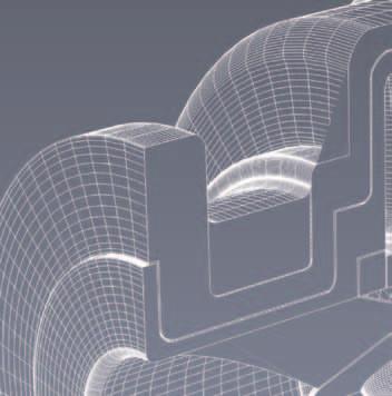
6 Construction and Components Magnetic drive pumps employ a spindle within the pump housing which supports the rotating parts (impeller and magnet capsule). The structure of magnetic drive pumps can be divided into two groups: rotating-spindle type and fixed-spindle type (where the spindle is fixed to the pump casing). IWAKI has a lineup of both types of pumps that can be selected to match your application. Rotating-Spindle Type MDW MDE These pumps have a metal-reinforced split plate that supports the rotating parts within the pump housing, giving them the advantage of increased structural strength. IWAKI MDW and MDE magnetic drive pumps employ this structure. Magnet capsule Sleeve O ring Bearing Thrust ring Split plate Impeller Impeller lock nut O ring Impeller nut Gasket Front casing 5

7 What is a magnetic drive pump? Construction and Components Drive magnet Bracket Rear casing support Rear casing cover Rear casing Gasket Bearing Sleeve Rear casing Split plate Front casing Spindle Impeller Magnet capsule 6
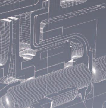
8 Fixed-Spindle Type MDM MXM AMP In a fixed-spindle type, both ends of the spindle are supported by the front and rear casing. Their simple structure and compact design provide for ease of maintenance and make them more resistant to abnormal operation. IWAKI MDM, MXM, and AMP magnetic drive pumps employ this structure. Rear thrust ring Rear casing Spindle Rear ring Gasket Bearing Liner ring Mouth ring Impeller/magnet capsule Front casing 7

9 What is a magnetic drive pump? Construction and Components Drive magnet Bracket Rear casing support Rear casing cover Rear ring Bearing Rear thrust ring Front casing Liner ring Mouth ring Spindle Rear casing Impeller Magnetic capsule 8
10 Features of magnetic drive pumps General Features Magnetic drive pumps do not require a shaft seal and employ materials in their construction that have excellent corrosion resistance, providing them with the following features. Leak-free Seal-less Structure Can safely handle hazardous fluids Drive (Power) Unit As described in "Principles of Magnetic Pumps," the magnetic force between drive and driven magnets must be stronger than motor torque. In a typical sealed centrifugal pump, the motor power required increases with the specific gravity of the fluid. In a magnetic pump, both the magnetic strength of the magnets and the motor power must increase. Dead Head Running Simple Structure Easy to maintain and overhaul Excellent Corrosion Resistance Can be used with a wide range of chemicals, including acids and alkalis If a pump is running with the discharge-side valve closed, friction heat will build up on the sliding parts within the pump and captive liquid. If the suction-side valve is closed, cavitation occurs almost immediately, which is not possible in any kind of pump, not just magnetic pumps. Accordingly, the suction-side valve should always be fully open, and the discharge-side valve should be open as required to maintain a minimum flow rate. Wide Fluid Temperature Range Glass fiber, carbon fiber, and other materials are added to create reinforced plastics. This technique significantly improves the tensile strength, bending elasticity modulus, and compressive stress of those materials. In addition, each part is reinforced using metal to improve thermal resistance and increase durability. Closed-discharge Closed-suction 9
11 What is a magnetic drive pump? Features of magnetic drive pumps Dry Running Dry running of all centrifugal pumps, not just magnetic pumps, will cause damage to the pump and is not recommended. Bearings made from ceramic materials have excellent thermal resistance and corrosion resistance, but friction heat will impact the surrounding parts. In addition, ceramics may crack due to rapid changes in temperature (thermal shock). If bearings are made from carbon-based material, part seizure is less likely to occur due to their self-lubrication, but dry running will hasten wear of the bearing. If bearings are made from fluorocarbon polymers, the bearing can be deformed and scorched due to heat generated by the bearing itself. Periodic inspection of wear components in accordance with the instruction manual and appropriate replacement of these components is required. Slurry In general, magnetic drive pumps are not suited for handling fluids containing slurry, although there is some variation in capability depending on the type of bearing material. If the bearing material is carbon-based or a fluorocarbon polymer, the handling of slurry is not allowed. If the bearing material is ceramic-based, the material has limited durability to friction with slurry. However, restrictions on handling slurry still apply for other wet end parts made from plastics (impeller, casing, etc.). The nature of slurry can vary, so regular testing to determine whether slurry can be handled is recommended. Dry running Component Life Magnetic drive pumps use sliding components such as bearings, sleeves or spindles, and mouth rings in a structure that requires liquid lubrication. The working life of these components is affected by various operating conditions, such as the nature of the fluid being pumped and the presence of slurry. In IWAKI magnetic drive pumps, the dimensions and clearances (gaps) are designed based on our standard, with wear limits stipulated for maintaining performance. 10
12 Internal Circulation Magnetic drive pumps employ a structure which supports the rotating parts (impeller/magnet capsule unit) within the pump housing using bearings. Because moving parts use slide bearings designed for fluid circulation, a portion of the fluid being pumped circulates within the pump. The flow of fluid inside the pump is called the internal circulation. This section describes the internal circulation using a fixed-spindle type pump as an example. Circulation around mouth ring Low-pressure fluid entering from the suction inlet is pressurized by the rotation of the impeller. The pressure within the casing increases with the distance from the center, especially, at the bottom of rear casing. Hence, a pressure differential occurs between the front and rear of the impeller/magnet capsule, giving rise to axial thrust force from the rear casing toward the suction inlet. The mouth ring and liner ring are displaced by this axial thrust force. The mouth ring has a gap that supplies fluid for cooling to the sliding surfaces, flowing in response to the pressure differential between the front casing and the suction inlet, and this fluid then flows back toward the impeller. (A in the diagram). Circulation around bearings The impeller/magnet capsule is also subjected to radial thrust force in addition to axial thrust force. The radial thrust occurs due to imbalance in pressure within the casing. In general, at flow rates lower than the design specification, the pressure is higher in the vicinity of the discharge outlet, which pushes the impeller away from the outlet. At flow rates higher than the design specification, the pressure is lower in the vicinity of the discharge outlet, which pushes the impeller toward the discharge outlet. A load is applied to the bearing and spindle, as they slide, in response to this radial force and the weight of the impeller/magnet capsule. The bearing has a gap that supplies fluid for cooling to the sliding surfaces, flowing in response to the pressure differential between the rear casing and the impeller inlet. This fluid then flows back toward the impeller. (B in the diagram). Bearing Spindle B Mouth ring Liner ring Impeller/magnet capsule unit Radial thrust Low pressure High pressure A Axial thrust 11
13 What is a magnetic drive pump? Features of magnetic drive pumps Magnetic Coupling Drive magnet Driven magnet N A magnetic coupling is a mechanism for transferring S power using magnetic force. The diagram below shows a cross-section of a magnetic pump. S N N S S Driven magnet Static state N Motor Drive magnet The magnet unit connected to the motor shaft is called the drive magnet, and the magnet unit connected to the impeller is called the driven magnet. The drive magnet and driven magnet rotate synchronously. For example, if the motor rotates at 3000 rpm, the impeller also rotates at 3000 rpm. The rear casing sandwiched between the two magnet units is made from plastics (non-magnetic) so that eddy current loss due to magnetic field induction in the casing cannot occur. As a result, there is no generation of heat due to eddy current and no loss of energy. The following information describes how the magnetic coupling transmits torque (rotational power). The first diagram shows a cross-section of the magnetic coupling. The drive magnet and driven magnet both have alternating North (N) and South (S) poles arranged at equal intervals. N and S poles are attracted toward each other. This diagram shows the relative positions of the poles when in a state of rest. This position generates no torque, and is referred to as the neutral position. In the second diagram, when the motor is running, the drive magnet leads the driven magnet in the direction of rotation by an angle θ. In this state, the N pole of the drive magnet pulls the S pole of the driven magnet (attraction) and simultaneously pushes the N pole of the driven magnet (repulsion). S S Direction of rotation Running state N N Thus, the drive magnet is applying torque to the driven magnet. There is a correlation between the angle θ and the torque generated. The maximum torque is generated when the N pole of the drive magnet is about halfway between the S and N poles of the driven magnet (θ max). The strength of the magnetic coupling is designed to always be higher than the rated power of the motor by a safety margin. This provides additional torque for acceleration when starting the motor. As a result, the drive magnet angle θ should never exceed θ max. However, if the applied load exceeds the design load, the two magnet units will slip poles (decoupling), losing synchronism and rendering the pump unable to pump fluid. S S θ N Attraction θ max Repulsion N 12

14 Distinguishing features of IWAKI s magnetic drive pumps Non contact system (PAT.) Drive magnet Driven magnet MDM MXM AMP Unique Design Withstand Dry Running. The pump design features a mechanism to withstand dry running. High magnetic power of the rare earth magnets prevents the magnet capsule from coming into contact with the thrust ring of the rear casing, thus preventing melting of fluororesin components due to heat generation. This greatly improves resistance to dry running in comparison with conventional magnetic drive pumps made of fluororesin. Note: Only CF type (fitted with high density carbon bearing) can be run dry. Dry running is not possible in the case of KK type. Drive magnet Driven magnet Bearing Rear ring Rear thrust Back pull-out system MDW MDE MDM AMP For ease of inspection and maintenance, this series employs the back pullout system. This enables one to conduct inspections internally and replace parts without removing piping. The pump is designed to include safety measures that prevent the liquid from leaking when the foot support is pulled back. Note: Pump base plate is required for the back pullout system. Rear casing support 13
 (International patent applied) MXM Internal flow circulation in the pump chamber is required in order to lubricate and cool bearings.")

.")
15 What is a magnetic drive pump? Distinguishing features of IWAKI s magnetic drive pumps Self radiation structure (PAT. PEND) (International patent applied) MXM Internal flow circulation in the pump chamber is required in order to lubricate and cool bearings. In the case of abnormal operation such as cavitation or airsucking operation, internal flow circulation can not Mganet capsule work properly because the balance of the pressure in the pump chamber is unstable and seizing or bearings is possibile. Most commonly, this phenomenon is occurs on small size pumps with a small flow rate range. Therefore, a heat dispersion holes are included in the magnet capsule of MXM series pumps and these holes make flow circulation smooth under abnormal operation inside of the rear casing. IWAKI refers to this design as Selfradiating construction (PAT). Heat-dispersion holes Highly durable structure MDW MDE MDM MXM AMP A ductile cast iron shell adds strength and durability to the Fluoroplastic wet ends. The rear casing which is subject to the highest stress, is reinforced with an FRP cover to increase strength. Additionally, large magnetic drive pumps employ three layer construction (PAT.) to improve durability and safety, even in long-term harsh operating conditions. Front casing Rear casing, Rear casing cover 14
16 Series lineup (by Construction and material) MDW MDE Parts MDW MDE 1 Front casing ETFE, PFA ETFE 2 Rear casing PFA PFA 3 Rear casing cover FRP FRP 4 Impeller CFRETFE, PFA CFRETFE 5 Impeller thrust SiC SiC 6 Impeller nut PFA CFRETFE 7 Split plate PFA PFA 8 Magnet capsule PFA PFA 9 Bearing SiC SiC 10 Sleeve SiC SiC 11 Thrust - SiC 12 Gasket PTFE PTFE 13 O ring Kalrez Kalrez, FKM, EPDM 15
17 What is a magnetic drive pump? Series lineup MDM MXM AMP Part names MDM MXM AMP Front casing CFRETFE, PFA CFRETFE CFRPP Rear casing CFRETFE, PFA CFRETFE CFRPP Rear casing cover FRP FRP FRP Impeller CFRETFE, PFA CFRETFE CFRPP Magnet capsule CFRETFE, PFA CFRETFE CFRETFE Bearing High density carbon, SiC High density carbon, SiC, Carbon, SiC High purity alumina ceramic Spindle High purity alumina ceramic, SiC High purity alumina ceramic, SiC High purity alumina ceramic, SiC Liner ring High purity alumina ceramic, SiC High purity alumina ceramic, SiC High purity alumina ceramic, SiC Mouth ring Filled PTFE, SiC Filled PTFE, SiC Filled PTFE, SiC Rear thrust Filled PTFE, PTFE CFRETFE, CFRPFA Filled PTFE Rear ring High purity alumina ceramic, SiC High purity alumina ceramic, SiC Gasket PTFE FKM, EPDM, Aflas, DAI-EL Perfluor PTFE O ring FKM, EPDM, Aflas, DAI-EL Perfluor 16
18 Series lineup (by Performance curve) Head [m] Hz 90 MDW MDM MDE AMP 20 MXM 10 Capacity [L/min] [m³/h] 17
19 What is a magnetic drive pump? Series lineup Head [m] Hz 90 MDM MDW MDE AMP 30 MXM Capacity [L/min] [m³/h] Note: The illustration shows the general performance. Please contact us for more details. 18
20 Topic Life-Cycle Costs What are the costs of operating and maintaining a pump? high cost of parts involved in the replacement of expensive components such as shaft seals and related personnel costs. Purchase costs for a pump and electricity costs for operation are well known elements of total cost. In addition, repair costs for periodic replacement of components, failure costs associated with pump malfunctions and disposal costs of the used pump also need to be factored in to the total cost. Let s compare the Life-Cycle Costs between a typical shaft sealed pump and a plastic magnetic drive pump. With limited data, we cannot go beyond a qualitative analysis. Nevertheless, the comparison shows some interesting trends: All these costs from purchase to disposal of the pump (total costs over a pump s working life) are known as the Life-Cycle Costs (LCC). The Life-Cycle Costs model has been developed for making a comprehensive assessment of the operating costs of a pump in order to monitor and improve the efficiency of pump operation. LCC = Cic + Cin + Ce + Co + Cm + Cs + Cenv + Cd Cic: Initial costs (purchase costs and piping costs) Cin: Installation costs (foundation costs and electrical work costs) Ce: Running costs (electricity costs and water charges) Co: Operating costs (wages and supervision costs of operators) Cm: Maintenance costs (maintenance and repair costs) Cs: Shut-down costs (costs associated with failure and downtime) Cenv: Environmental costs (liquid waste disposal costs and leakage prevention costs) Cd: Disposal costs (Various costs associated with disposal) Initial Cost (Cic): Magnetic drive pumps tend to cost more. This is because expensive magnetic components are used in the coupling parts and the wetted parts are molded using costly fluoroplastic materials. Running Costs (Ce): Again, in many cases shaft sealed pumps seem to have a cost advantage. The reason is that the impeller and the casings of a magnetic drive pump, which could have a significant impact on pump efficiency, must be molded in resin and their configurations are limited. In recent years, however, new solutions for reducing the running costs have been developed, by improving drive efficiency resulting from the use of high-efficiency motors and inverters. Maintenance Costs (Cm): It is clear that magnetic drive pumps enjoy an overwhelming advantage. No shaft seals means no The pie chart below represents a breakdown of the Life-Cycle Costs of a typical shaft sealed pump. Clearly the initial costs and running costs make up more than half of the total outlay. replacement of costly components, such as mechanical seals, and thus no need for skilled maintenance technicians. In addition, fluoroplastic-made materials with Maintenance costs Initial costs Running costs strong corrosion resistance will drastically reduce the need for the replacement of worn parts. In addition, in recent years with increasing awareness of adverse environmental impacts, the costs of liquid waste disposal (Cenv) in chemical plants are steadily growing. Other costs Surprisingly, maintenance costs represent approximately one-third of the total expenditure. This is likely due to the Considering these factors, magnetic drive pumps with no possibility of leakage are increasing the smart choice for many demanding applications. 19
21 Model selection 20
22 Selection Procedure The following diagram shows the overall recommended decision flow for selecting a pump. STEP 1 Planning 1.1 Check pipe layout 1.2 Determine the required flow rate 1.3 Check the fluid properties STEP 2 Calculation of total head 2.1 Calculate the length of pipes 2.2 Calculate the pipe resistance 2.3 Calculate the total head STEP 3 Calculation of NPSHa STEP 4 Determine required specifications STEP 5 Pump selection 5.1 Select provisional model 5.2 Review NPSH NPSHa > NPSHr +0.5 m Yes 5.3 Calculate kinematic viscosity Kinematic viscosity > 4.3 cst Yes 5.4 Correct the performance 5.5 Review pump performance Meet required specifications? Yes 5.6 Review power Motor rating > required shaft power 1.1 Yes 5.7 Select materials No No No No No STEP 6 Pump Model Decision 21
23 Model selection Selection Procedure STEP 1 Planning Plan the overall system, from the fluid supply tank to the fluid deliver tank, in order to define the specifications for the pump. 1.1 Check pipe layout Determine the positional relationship between the supply tank, pump, and delivery tank to determine the size and length of the connecting pipes. This will also determine the specifications of fittings, such as valves and elbow joints. The following diagram shows an example of the recommended pipe layout. The pump should be mounted in the vicinity of the supply tank. Pipework for positive inlet pressure (flooded suction) is recommended. In particular, the suction inlet pipe should be thick, short, and straight as a rule. Refer to "Piping design tips and guide" on page Check the fluid properties Check the properties of the fluid that will be pumped including fluid name, fluid temperature, density, specific gravity, viscosity, and saturated vapor pressure. In general, high-density and low-temperature chemicals tend to have a high viscosity. Extra precautions are required if handling hazardous chemicals, such as caustic soda and sulfuric acid, which have a high viscosity at low temperatures. If a pump is restarted some time after pumping was stopped, any increase in viscosity accompanying the temperature drop in the fluid may lead to overloading of the motor. If the fluid contains slurry, check the slurry concentration, hardness, and grain size. Magnetic pumps made of plastics are generally unsuitable for pumping slurry. Additional steps for removing slurry before the magnetic pump are recommended. Refer to "Specific Gravity/Viscosity of Major Fluids" on page 51, and "Chemicals Requiring Caution" on page Determine the required flow rate Determine the maximum flow rate needed by the system. If you want to control the flow rate, the pump should be selected to cover the maximum flow rate. Note that a minimum flow rate of the pump needs to be observed. Recommended pipe layout example Pipe support Valve Check valve Valve Air bleed line Pressure gauge Supply tank Valve Vacuum gauge Expansion joint Valve Suction pipe Pipe support Drain 22
24 STEP 2 Calculation of total head Calculate the total system head based on the pipe layout and the required flow rate. 2.1 Calculate the length of pipes Calculate the combined length of the suction inlet pipe and discharge outlet pipe based on the pipe layout. Elbow joints, valves, and other fittings will introduce a higher pipe resistance compared to a corresponding straight section of pipe, and these must be converted to equivalent lengths of straight pipe for calculating the pipe resistance. This virtual pipe length is referred to as the "equivalent length". If the tanks are open-air. The pressure in each tank is the atmospheric pressure. Ht : Total head [m] Hac : System static head [m] Hf : System friction head loss [m] Hd : Discharge static head [m] Hs : Suction static head [m] Hac System static head Hs Suction static head Ht = Hac + Hf = Hd - Hs + Hfs + Hfd Hfd Discharge friction head loss Supply tank (open-air) Hfs : Suction friction head loss [m] Hfd : Discharge friction head loss [m] Deliver tank (open-air) Hd Discharge static head Refer to "Equivalent straight pipe length of typical couplings" on page 45. Hfs Suction friction head loss Pump 2.2 Calculate the pipe resistance Determine the flow velocity from the pipe diameter and the flow rate. Then calculate the pipe resistance (friction head loss) for the flow velocity. The pipe resistance is calculated using the Darcy-Weisbach equation. If the tanks are sealed. The pressure differential inside the tanks must be included in the calculation. Ht = Hac + Hf + = Hd - Hs + Hfs + Hfd + ( Pd - Ps ) 106 ρ g ( Pd - Ps ) 106 ρ g [m] [m] Pipe resistance: Hf = f L D V2 2g f : Friction coefficient ( /D for new pipes) L : Pipe length [m] D : Pipe diameter [m] (use the inner diameter) V : Fluid velocity [m/s] g : Acceleration of gravity [m/s 2 ] [m] Ht : Total head [m] Hac : System static head [m] Hf : System friction head loss [m] Pd : Pressure inside output tank [MPa] Ps : Pressure inside supply tank [MPa] ρ : Fluid density [kg/m 3 ] g : Acceleration of gravity [9.8 m/s 2 ] Hd : Discharge static head [m] Hs : Suction static head [m] Hfs : Suction friction head loss [m] Hfd : Discharge friction head loss [m] Discharge tank (sealed) Pd You can use the "Quick reference chart for pipe resistance" on page 46 to determine pipe resistance, but for accurate results it is recommended that it be calculated directly from the equation above if you are able to determine is the inside diameter of the pipe. 2.3 Calculate the total head The total system head is the sum of the pipe resistance and the difference in elevation of the fluid surfaces in the supply tank and the deliver tank. Hac System static head Hs Suction static head Supply tank (sealed) Ps Hfd Discharge friction head loss Hfs Suction friction head loss Pump Hd Discharge static head 23
25 Model selection Selection Procedure STEP 3 Calculation of NPSHa STEP 4 Determine required specifications Calculate the NPSHa and review the suction conditions. NPSH (Net Positive Suction Head) is a value of the energy pushing fluid into the suction inlet of a running pump expressed in units of head [m]. It is an important value that must be considered to prevent cavitation. Here, we calculate the NPSHa (NPSH available) from the fluid properties and pipe conditions. This value will then be compared with the NPSHr (NPSH required) which is a characteristic of the pump in STEP 5. NPSHa is calculated using the following equation. Summarize the information required for selecting a pump based on the information obtained thus far. NPSHa = ( PA - Pv ) 106 ρg ± Hs - Hfs [m] PA : Absolute pressure on surface fluid in the supply tank [MPa] If the tank is open to the atmosphere, (nominally standard atmospheric pressure) = [MPa] Pv : Fluid vapor pressure at the pump inlet temperature [MPa] Hs : Suction static head (height of inlet port center relative to supply tank fluid level) [m] (Flooded is positive, Lift-up is negative) Hfs : Suction friction head loss [m] ρ : Fluid density [kg/m 3 ] g : Acceleration of gravity 9.8 [m/s 2 ] Required specification Discharge rate (nominal) Suction rate (maximum) Total head Discharge head Suction head NPSHa Location Operation mode Supply voltage, frequency L/min L/min m m m m Indoor/Outdoor Continuous/Intermittent hr/day V Hz Lower (Flooded): Hs is added Supply tank (open-air) PA Hs Pump Fluid handling Fluid name Concentration % Temperature C Viscosity mpa s Specific gravity Saturated vapor pressure kpa Slurry Yes/No Slurry concentration, particle size, hardness wt%, μm, Hs Higher (Lift-up): Hs is subtracted Pump Hs PA 24
26 STEP 5 Pump selection With the required information summarized, we can proceed to select a pump. 5.1 Select provisional model Select a pump that satisfies the required conditions from the product catalog or from individual standard performance curves. Refer to the performance curves in the series overview on page 17. The standard performance curves for each model must be checked separately. Contact IWAKI for more information. 5.2 Review NPSH The NPSHr required for a pump is determined individually for each model of pump, and can be read from the individual standard performance curves. In order to avoid cavitation, the NPSHa must be greater than the NPSHr. In addition, it is also necessary to have a margin of more than 0.5m above the NPSHa. Therefore, check that the following condition is satisfied. NPSHa > NPSHr Calculate kinematic viscosity Calculate the kinematic viscosity from the fluid viscosity and density. Kinematic viscosity: ν = ν : Kinematic viscosity [m 2 /s] or [cst] μ : Viscosity [mpa s] or [cp] ρ : Density [kg/m 3 ] = γ : Specific gravity 10 3 When the kinematic viscosity ν is less than 4.3, effects of viscosity on pump performance can be ignored. Proceed to STEP 5.6. When the kinematic viscosity ν is greater than 4.3, viscosity will affect pump performance, and performance revision is required. Proceed to STEP 5.4. However, if the specific gravity of the fluid is greater than 1, even if the kinematic viscosity is less than 4.3, the power rating will need to be modified. 5.4 Correct performance Refer to the flow rate and head at the point of maximum efficiency of the pump from the standard performance curves. Read the viscosity correction factor (head Ch, flow rate Cq, efficiency Ce) from the performance correction curve. μ ρ 10³ [m²/s] Refer to Performance correction curve on page 53. If the NPSHr is insufficient, return to STEP 1.1 and see if you can resolve the problem by reviewing the pipework conditions or other factors. If the condition above is still not satisfied, return to STEP 5.1 and select another model with a lower NPSHr. Refer to Remedies when NPSHa is insufficient on page 52. Calculate the revised shaft power from the individual correction factors Corrected head = Hw Ch Corrected flow rate = Qw Cq Corrected efficiency = Ew Ce Corrected shaft power Specific gravity Corrected head [m] = Corrected flow rate [L /min] Corrected efficiency [%] /
27 Model selection Selection Procedure 5.5 Review pump performance Check whether the calculated corrected performance satisfies the required specifications. If the required specifications are not satisfied, the performance must be reviewed again from STEP Review power Calculate the shaft power and review the size of motor to connect to the pump. Required shaft power: SP = γ Q H η / [kw] STEP 6 Pump Model Decision Refer to the connection flange standards, drain requirement, and pump base plate requirement of the specifications. Note that a pump base is required to use the back pullout configuration for maintenance. A drain may also be required, depending on the installation location and the type of maintenance performed. Finally, select the pump model based on above consideration. γ : Specific gravity Q : Flow rate [L/min] H : Head [m] η : Pump efficiency [%] The shaft power of the pump should be larger than calculated to cover changes in operating point, type of fluid, or other factors. A margin of at least 10% is recommended to maintain normal operation. Select a pump with an equivalent or higher rated output motor from the product lineup. 5.7 Select materials Select the materials of wet ends the handled fluid. Consider the optimal combination of corrosion resistance, model, series structure, and other factors. For models and series structure of each type of pump, Refer to Product Specifications on page
28 Selection example 1 (Sodium hydroxide) Here we will consider some actual case studies, and follow the procedure to select a pump. In this example, sodium hydroxide is pumped to a process line from a storage tank located some distance away. The static head is low, and the discharge pipe length is long. Discharge pipe length: 85m Storage tank (open air) Sodium hydroxide Pump 3m 5m 8m Deliver tank (open-air) STEP 1 Planning STEP 2 Calculation of total head 1.1 Check pipe layout Hs : Suction static head 5 [m] Hd : Discharge static head 8 [m] Hac : System static head 3 [m] 1.2 Determine the required flow rate Nominal flow rate : 3000 [L/min] Maximum flow rate : 3000 [L/min] Required flow rate Q = : 3000 [L/min] 1.3 Check the fluid properties Fluid handling Fluid name Sodium hydroxide (NaOH) Concentration 20 % Temperature 20 C Viscosity 4.43 mpa s Specific gravity 1.22 Saturated vapor pressure 2.2 kpa Slurry No 2.1 Calculate the length of pipes Suction pipe Type Qty Size Equivalent length Straight pipe 1 125A 5 m Gate valve (flange) 1 125A 1 m Total 6 [m] Discharge pipe Type Qty Size Equivalent length Straight pipe 1 100A 85 m Gate valve (flange) 1 100A 0.9 m 90 elbow (flange) 2 100A 3.6 m Swing check valve (flange) 1 100A 11.6 m Total [m] 2.2 Calculate the pipe resistance Calculate the flow velocity in the suction pipe and discharge pipe from the pipe diameter and flow rate. 27
29 Model selection Selection example 1 (Sodium hydroxide) Suction pipe D : Pipe inner diameter [m] S : Cross-sectional area [m 2 ] Q : Flow rate 0.05 [m 3 /s] Suction pipe flow velocity: V = Discharge pipe D : Pipe inner diameterr 0.1 [m] S : Cross-sectional area [m 2 ] Q : Flow rate 0.05 [m 3 /s] Discharge pipe flow velocity: V = Calculate the pipe resistance of the suction pipe and discharge pipe. The pipe resistance is calculated using the Darcy-Weisbach equation. Pipe resistance: Hf = f 2.3 Calculate the total head In this example, both tanks are open-air. The total head is given by the following equation. L D V2 2g Q S Q S [m] = 4.07 [m/s] = 6.37 [m/s] Suction pipe f : Friction coefficient ( /D for new pipes) L : Pipe length 6 [m] D : Pipe inner diameter [m] V : Fluid velocity 4.07 [m/s] g : Acceleration of gravity 9.8 [m/s 2 ] Suction friction head loss: Hfs = 0.97 [m] Discharge pipe f : Friction coefficient ( /D for new pipes) L : Pipe length [m] D : Pipe inner diameter 0.1 [m] V : Fluid velocity 6.37 [m/s] g : Acceleration of gravity 9.8 [m/s 2 ] Discharge friction head loss: Hfd = [m] Total head Ht = Hac + Hfs + Hfd [m] Hac : System static head 3 m Hfs : Suction friction head loss 0.97 m Hfd : Discharge friction head loss m Total head Ht = 56.3 [m] STEP 3 Calculation of NPSHa Calculate the NPSHa and review the suction conditions. For open-air tanks, the NPSHa is given by the following equation. STEP 4 Summarize the information obtained thus far. Required specification Discharge rate (nominal) Suction rate (maximum) Total head Discharge head Suction head NPSHa NPSHa = PA : Atmospheric pressure [MPa] Pv : Saturated vapor pressure 2.2 [kpa] = [MPa] Hs : Suction static head 5 [m] Hfs : Suction friction head loss 0.97 [m] ρ : Fluid density 1220 [kg/m 3 ] (Specific gravity 1.22) g : Acceleration of gravity 9.8 [m/s 2 ] Location Operation mode Supply voltage, frequency Connection standard Pump drain Pump base ( PA - Pv ) 106 ρg ± Hs - Hfs [m] NPSHa = 12.3 [m] Determine required specifications 3000 L/min 3000 L/min 56.3 m 5 m 8 m 12.3 m Indoor 2 hr/day 400 V, 50 Hz JIS 10K Required Required Fluid handling Fluid name Sodium hydroxide Concentration 20 % Temperature 20 C Viscosity 4.48 mpa s Specific gravity 1.22 Saturated vapor pressure 2.2 kpa Slurry No 28
30 STEP 5 Pump selection 5.3 Calculate kinematic viscosity 5.1 Select provisional model Select a pump that satisfies the required conditions from a product catalog or from individual standard performance curves. In this case, the following model is selected. Provisional model: MDW _ 2 Check the pump performance with the required specifications using the standard performance curves for the selected pump Standard performance curve SP μ Kinematic viscosity: ν = 10 3 ρ μ : Viscosity 4.43 [mpa s] or [cp] ρ : Density 1220 [kg/m 3 ] (Specific gravity 10 3 ) Kinematic viscosity: ν = 3.63 [cst] In this case, the kinematic viscosity ν is less than 4.3, so the impact on pump performance due to viscosity can be ignored. However, if the fluid viscosity is greater than 1, the power specification needs to be revised. Proceed to step Correct performance Not required in this case Review pump performance H-Q Not required in this case η NPSHr Review power 10 Efficiency η (%) Shaft power SP (kw) Total head H (m) 1000 Discharge head Q (L/min) NPSHr (m) Calculate the shaft power and review the size of motor to connect to the pump. Q : Flow rate 3000 [L/min] H : Head 64 [m] SP : Shaft power 49 [kw] η : Efficiency 64 [%] NPSHr : 6.4 [m] 5.2 Review NPSH NPSHa=10.3 [m], NPSHr=6.4 [m] NPSHa > NPSHr The calculated NPSHa and NPSHr satisfy the above relationship Required shaft power: SP = γ : Specific gravity 1.22 Q : Flow rate 3000 [L/min] H : Head 64 [m] η : Pump efficiency 64 [%] γ Q H η / [kw] Required shaft power: SP = 59.7 [kw] The shaft power of the pump should be larger than planned to cover any changes in operating point, type of fluid, or other cause, hence a margin of at least 10% should be maintained for normal operation. 29
31 Model selection Selection example 1 (Sodium hydroxide) Calculate a revised shaft power by adding a 10% safety margin to the calculated required shaft power. Corrected shaft power: SP = = 65.7 [kw] Therefore, the required motor size must deliver 65.8 kw or higher. Select a pump with 75 kw rated output from the product lineup. 5.7 Select materials Select the materials of wet ends for the handled fluid. The only material available for MDW pump spindlebearing is an SiC-SiC combination, which can be used with Sodium Hydroxide. The O-ring material is the standard Kalrez, which can also be used with caustic soda. Therefore, the material symbol in the model name is EKZ. STEP 6 Pump Model Decision Check the required flange connection standard and the requirements for pump drain and pump base before making a final decision on the pump model. Selected model: MDW E K Z C 750 J - D 2 30
32 Selection example 2 (Hydrochloric acid) In this example, the discharge is hydrochloric acid spray used in the etching process. The pressure of the nozzle tip on the discharge side must be taken into account. Nozzle spray 1m Hydrochloric acid etching bath Pump 2m 3m STEP 1 Planning STEP 2 Calculation of total head 1.1 Check pipe layout Hs : Suction static head 2 [m] Hd : Discharge static head 3 [m] Hac : System static head 1 [m] Nozzle tip pressure: 0.2 [MPa] 1.2 Determine the required flow rate Required flow rate Q = : 300 [L/min] 1.3 Check the fluid properties Fluid handling Fluid name Hydrochloric acid (HCl) Concentration 30 wt% Temperature 20 C Viscosity 1.73 mpa s Specific gravity 1.15 Saturated vapor pressure 2.2 kpa Slurry No 2.1 Calculate the length of pipes Suction pipe Type Qty Size Equivalent length Straight pipe 1 50 A 1 m Gate valve (screw) 1 50 A 0.5 m Total 1.5 [m] Discharge pipe Type Qty Size Equivalent length Straight pipe 1 40 A 7 m Gate valve (screw) 1 40 A 0.4 m 90 elbow (screw) 1 40 A 2.3 m Total 9.7 [m] 2.2 Calculate the pipe resistance Calculate the flow velocity in the suction pipe and discharge pipe from the pipe diameter and flow rate. 31
33 Model selection Selection example 2 (Hydrochloric acid) Suction pipe D : Pipe inner diameter 0.05 [m] S : Cross-sectional area [m 2 ] Q : Flow rate [m 3 /s] Suction pipe flow velocity: V = Discharge pipe D : Pipe inner diameter 0.04 [m] S : Cross-sectional area [m 2 ] Q : Flow rate [m 3 /s] Discharge pipe flow velocity: V = Calculate the pipe resistance of the suction pipe and discharge pipe. The pipe resistance is calculated using the Darcy-Weisbach equation. Q S Q S = 2.55 [m/s] = 3.98 [m/s] STEP 3 Calculation of NPSHa Calculate the NPSHa and review the suction conditions. For open-air tanks, the NPSHa is given by the following equation. NPSHa = ( PA - Pv ) 106 ρg ± Hs - Hfs [m] PA : Atmospheric pressure [MPa] Pv : Saturated vapor pressure 2.2 [kpa] = [MPa] Hs : Suction static head 2 [m] Hfs : Suction friction head loss 0.3 [m] ρ : Fluid density 1150 [kg/m 3 ] (Specific gravity 1.15) g : Acceleration of gravity 9.8 [m/s 2 ] NPSHa = [m] Pipe resistance: Hf = f L D V2 2g [m] Suction pipe f : Friction coefficient ( /D for new pipes) L : Pipe length 1.5 [m] D : Pipe inner diameter 0.05 [m] V : Fluid velocity 2.55 [m/s] g : Acceleration of gravity 9.8 [m/s 2 ] Suction friction head loss: Hfs = 0.30 [m] Discharge pipe f : Friction coefficient ( /D for new pipes) L : Pipe length 9.7 [m] D : Pipe inner diameter 0.04 [m] V : Fluid velocity 3.98 [m/s] g : Acceleration of gravity 9.8 [m/s 2 ] Discharge friction head loss: Hfd = 6.36 [m] 2.3 Calculate the total head In this example, the tank is open-air. Calculate the total head taking into account the nozzle tip pressure. Total head Ht = Hac + Hfs + Hfd [m] Hac : System static head 1 m Hfs : Suction friction head loss 0.3 m Hfd : Discharge friction head loss 6.36 m Total head Ht = 7.7 [m] Taking into account the 0.2 [MPa] nozzle tip pressure: ρg 106 = Total head Ht = 25.4 [m] STEP 4 Determine required specifications Summarize the information obtained thus far. Required specification Discharge rate (nominal) 300 L/min Suction rate (maximum) 300 L/min Total head (including nozzle tip pressure) 25.4 m Discharge static head 3 m Suction static head 2 m NPSHa 10.5 m Location Outdoor Operation mode 24 hr/day Supply voltage, frequency 200 V, 50 Hz Connection standard JIS 10K Pump drain Not required Pump base Required Fluid handling Fluid name Hydrochloric acid Concentration 30 wt% Temperature 20 C Viscosity 1.73 mpa s Specific gravity 1.15 Saturated vapor pressure 2.2 kpa Slurry No 32
34 STEP 5 Pump selection 5.3 Calculate kinematic viscosity 5.1 Select provisional model Select a pump that satisfies the required conditions from a product catalog or from individual standard performance curves. In this case, the following model is selected. Provisional model: MXM 54 _ _ - _ Check the pump performance with the required specifications using the standard performance curves of the selected pump. Standard performance curve μ Kinematic viscosity: ν = 10³ ρ μ : Viscosity 1.73 [mpa s] or [cp] ρ : Density 1150 [kg/m 3 ] (Specific gravity 10 3 ) Kinematic viscosity ν = 1.5 [cst] In this case, the kinematic viscosity ν is less than 4.3, so the impact on pump performance due to viscosity can be ignored. However, if the fluid viscosity is greater than 1, the power specification needs to be revised. Proceed to step Correct performance Not required in this case SP 5.5 Review pump performance Not required in this case H-Q η Review power NPSHr Calculate the shaft power and review the size of motor to connect to the pump. Efficiency η (%) Shaft power SP (kw) Total head H Discharge head Q (L/min) 300 (m) NPSHr (m) Q : Flow rate 300 [L/min] H : Head 27 [m] SP : Shaft power 2.75 [kw] η : Efficiency 48 [%] NPSHr : 2.6 [m] Required shaft power: SP = γ : Specific gravity 1.15 Q : Flow rate 300 [L/min] H : Head 27 [m] η : Pump efficiency 48 [%] γ Q H η / [kw] Required shaft power: SP = 3.16 [kw] 5.2 Review NPSH NPSHa=10.5 [m], NPSHr=2.6 [m] NPSHa > NPSHr The calculated NPSHa and NPSHr satisfy the above relationship The shaft power of the pump should be larger than planned to cover any changes in operating point, type of fluid, or other cause, hence a margin of at least 10% should be maintained for normal operation. 33
35 Model selection Selection example 2 (Hydrochloric acid) Calculate a revised shaft power by adding a 10% safety margin to the calculated required shaft power. STEP 6 Pump Model Decision Corrected shaft power: SP = = 3.48 [kw] Therefore, the required motor size must deliver 3.48 kw or higher. Select a pump with 3.7 kw rated output from the product lineup. Check the required flange connection standard and the requirements for pump drain and pump base before making a final decision on the pump model. Selected model: MXM E CF V J - B 5.7 Select materials Select the materials that can be used for wet ends for the handled fluid. The following options are available for selecting the bearing/spindle material for MXM pumps. Bearing/spindle material CF type Carbon/Alumina ceramics FF type Alumina ceramics/alumina ceramics KK type SiC/SiC The CF type combination is recommended for its dryrunning capability. The following options are available for the O-ring material. O-ring material V type A type FKM (Fluoro Rubber) AFLAS E type (EPDM) is also available, but it is not suitable for acidic chemicals. In this example, select V type. Therefore, the material symbol in the model name is E CF V. 34
36 Selection example 3 (Sulfuric acid) In this example, the pumps transport sulfuric acid. Sulfuric acid is a slightly viscous liquid. Kinematic viscosity, in particular, must be checked. 10 m 8 m Sulfuric acid Pump 2 m STEP 1 Planning STEP 2 Calculation of total head 1.1 Check pipe layout Hs : Suction static head 2 [m] Hd : Discharge static head 10 [m] Hac : System static head 8 [m] 1.2 Determine the required flow rate Nominal flow rate : 400 [L/min] Maximum flow rate : 400 [L/min] Required flow rate Q = : 400 [L/min] 1.3 Check the fluid properties Fluid handling Fluid name Sulfuric acid (H₂SO₄) Concentration 98 wt% Temperature 25 C Viscosity 26 mpa s Specific gravity 1.84 Saturated vapor pressure kpa Slurry No 2.1 Calculate the length of pipes Suction pipe Type Qty Size Equivalent length Straight pipe 1 50A 5 m Gate valve (flange) 1 50A 0.5 m Total 5.5 [m] Discharge pipe Type Qty Size Equivalent length Straight pipe 1 40 A 18 m Check valve (screw) 1 40 A 4.6 m Gate valve (screw) 1 40 A 0.4 m 90 elbow (screw) 1 40 A 2.3 m Total 25.3 [m] 2.2 Calculate the pipe resistance Calculate the flow velocity in the suction pipe and discharge pipe from the pipe diameter and flow rate. 35
37 Model selection Selection example 3 (Sulfuric acid) Suction pipe D : Pipe inner diameter 0.05 [m] S : Cross-sectional area [m 2 ] Q : Flow rate [m 3 /s] Suction pipe flow velocity: V = Discharge pipe D : Pipe inner diameter 0.04 [m] S : Cross-sectional area [m 2 ] Q : Flow rate [m 3 /s] Discharge pipe flow velocity: V = Calculate the pipe resistance of the suction pipe and discharge pipe. The pipe resistance is calculated using the Darcy-Weisbach equation. Q S Q S = 3.40 [m/s] = 5.31 [m/s] STEP 3 Calculation of NPSHa Calculate the NPSHa and review the suction conditions. For open-air tanks, the NPSHa is given by the following equation. NPSHa = ( PA - Pv ) 106 ρg ± Hs - Hfs[m] PA : Atmospheric pressure [MPa] Pv : Saturated vapor pressure [kpa] = [MPa] Hs : Suction static head 2 [m] Hfs : Suction friction head loss 1.94 [m] ρ : Fluid density 1840 [kg/m 3 ] (Specific gravity 1.84) g : Acceleration of gravity 9.8 [m/s 2 ] NPSHa = 5.67 [m] Pipe resistance: Hf = f L D V2 2g [m] Suction pipe f : Friction coefficient ( /D for new pipes) L : Pipe length 5.5 [m] D : Pipe inner diameter 0.05 [m] V : Fluid velocity 3.40 [m/s] g : Acceleration of gravity 9.8 [m/s 2 ] Suction friction head loss: Hfs = 1.94 [m] Discharge pipe f : Friction coefficient ( /D for new pipes) L : Pipe length 23.9 [m] D : Pipe inner diameter 0.04 [m] V : Fluid velocity 5.31 [m/s] g : Acceleration of gravity 9.8 [m/s 2 ] Discharge friction head loss: Hfd = 27.9 [m] 2.3 Calculate the total head In this example, both tanks are open-air. The total head is given by the following equation. Total head Ht = Hac + Hfs + Hfd [m] Hac : System static head 8 m Hfs : Suction friction head loss 1.94 m Hfd : Discharge friction head loss 27.9 m Total head Ht = 37.8 [m] STEP 4 Determine required specifications Summarize the information obtained thus far. Required specification Discharge rate (nominal) 400 L/min Suction rate (maximum) 400 L/min Total head 37.8 m Discharge static head 10 m Suction static head 2 m NPSHa 5.67 m Location Outdoor Operation mode 8 hr/day Supply voltage, frequency 200 V, 50 Hz Connection standard JIS 10K Pump drain Required Pump base Required Fluid handling Fluid name Sulfuric acid Concentration 98 wt% Temperature 25 C Viscosity 26 mpa s Specific gravity 1.84 Saturated vapor pressure kpa Slurry No 36
38 STEP 5 Pump selection 5.3 Calculate kinematic viscosity 5.1 Select provisional model Select a pump that satisfies the required conditions from a product catalog or from individual standard performance curves. In this case, the following model is selected. Provisional model: MDM _ F - _ 2 Check the pump performance with the required specifications using the standard performance curves for the selected pump Standard performance curve SP H-Q μ Kinematic viscosity: ν = 1000 ρ μ : Viscosity 26 [mpa s] or [cp] ρ : Density 1840 [kg/m 3 ] (Specific gravity 10 3 ) Kinematic viscosity: ν = 14.1 [cst] in this example, the fluid viscosity ν is greater than 4.3, so the power specification needs to be revised. Proceed to step Correct performance Refer to the flow rate and head at the point of maximum efficiency of the pump from the standard performance curves. Maximum efficiency point Flow rate: 450 L/min, Head: 41 m Read the viscosity correction factor (head Ch, flow rate Cq, efficiency Ce) from the performance correction curve η NPSHr Ce 88% 70 Viscosity correction factor [%] Cq 100% Ch 98% Ch Cq 60 Efficiency η (%) Shaft power SP (kw) Total head H Discharge head Q (L/min) (m) NPSHr (m) Q : Flow rate 400 [L/min] H : Head 43 [m] SP : Shaft power 6.5 [kw] η : Efficiency 43 [%] NPSHr : 3.7 [m] 5.2 Review NPSH NPSHa= 5.67 [m], NPSHr=3.7 [m] NPSHa > NPSHr The calculated NPSHa and NPSHr satisfy the above relationship Head [m] Discharge head Viscosity [SSU] Intersection Intersection Viscosity [cst] Ce 1. Intersection 1 between flow rate at maximum efficiency of 450 L/min and head of 41 m. 2. Extend a horizontal line from intersection 1 to get intersection 2 with kinematic viscosity of 14.1 cs. 3. Extend a vertical line from intersection 2 to read Ch, Cq, and Ce [m³/min] [L/min] 37
39 Model selection Selection example 3 (Sulfuric acid) Calculate the corrected head, corrected flow rate, corrected efficiency, and corrected shaft power. Corrected head = Head : Hw Ch = = 42.1 [m] Corrected flow rate = Flow rate : Qw Cq = = 400 [L/min] Corrected efficiency = Efficiency : Ew Ce = = 37.8 [%] Corrected shaft power Specific gravity Corrected Corrected head [m] flow rate [L/min] = 10-3 Corrected efficiency [%] / 100 = 13.4 [kw] 5.7 Select materials Select the materials of wet ends for the handled fluid. On the MDM pumps, the main wet-end plastic material that can be selected is CFRETFE (E type) or PFA (P type) depending on liquid properties. If corrosion is not a problem, CFRETFE (E type) is recommended for a cost advantage. The following options are available for the bearing/ spindle material. Bearing/spindle material CF type Carbon/Alumina ceramics KK type SiC/SiC 5.5 Correct performance Check whether the calculated corrected performance satisfies the required specifications. Required specification Flow rate: 400 L/min, Head: 37.8 m Corrected performance Flow rate: 400 L/min, Head: 42.1 m You can now check to see if the required specifications are satisfied. 5.6 Review power Review the size of motor that supplies the corrected shaft power. The shaft power of the pump should be larger than planned due to cover any changes in operating point, type of fluid, or other cause, hence a margin of at least 10% should be maintained for normal operation. The CF type combination is recommended for its dryrunning capability. Therefore, the material symbol in the model name is E CF. STEP 6 Pump Model Decision Check the required flange connection standard and the requirements for pump drain and pump base before making a final decision on the pump model. Selected model: MDM E CF F 150 J - D 2 Corrected shaft power: SP = = 14.7 [kw] Therefore, the required motor size must deliver 14.7 kw or higher. Select a pump with 15 kw rated output from the product lineup. 38
40 Topic How to determine NPSHr How to calculate the NPSHr of a pump? NPSHr is the minimum head (water head) required by a pump to prevent cavitation in the pump. Although there are several ways of measuring the NPSHr, including throttling the suction valve, reducing the pressure in the suction tank and increasing the liquid temperature, the principle behind any method is the same: reducing the suction head until cavitation occurs in the pump. It is difficult to clearly determine the exact point where the cavitation occurs in the course of reducing the suction head. Today, it is generally considered that cavitation occurs when the pump shows a reduction in total head of 3%. The NPSHr value determined in this way, in particular, is sometimes called NPSH3. Now, let us take the method of throttling a suction valve as an example to explain the testing procedure. Q : Discharge P1 : Suction pressure P2 : Discharge pressure V1 : Suction pipe flow V2 : Discharge pipe flow The figure above shows the outline of the NPSHr measuring system. First, start up the pump with the suction valve fully opened, and then adjust the discharge valve until the flow rate reaches a certain level. The total head measured at this point is used as a reference. Tank Flowmeter Q P1 V1 V2 Pressure gauge P2 Next, throttle the suction valve slightly. Because P1 is reduced due to pressure loss, NPSH is decreased. To compensate the reduction in flow rate, open the discharge valve a little bit to restore the flow rate to its original level. By repeating the steps described above, calculate the total head for each case while gradually reducing the NPSH value. If all of the intersections of each total head and each NPSH value are plotted on the graph, a curve will appear as shown in the figure below. Total head : H [m] Reference total head 3% reduction NPSHr [m] NPSH [m] Finally, the NPSHr value at this flow rate can be determined by locating the intersection of the minus 3% line from the reference total head and the NPSH curve. Because the NPSHr of a pump varies with the flow rate, repeat the above testing procedure at various flow rates. Once all the calculated NPSHr values are plotted on the graph, the NPSHr characteristic curve can eventually be obtained. Refer to Total head of the glossary on page 74. Where PA is standard atmospheric pressure = [Pa]; and Pv is saturated vapor pressure of room temperature water = 2339[Pa], Total head in this condition can be calculated as follows: NPSH = = [m] Where H (total head) = [m]; and NPSH = 0.24 [m] It can be confirmed that m of NPSH is already available at the tank level. NPSHr [m] Flow rate [L/min] 39
41 Reference 40
42 Piping design tips and guide In order to safety use and maximize the performance of the pump, Please consider the following notes when planning piping, design and construction. In addition, please be sure to read the instruction manual when installing and using the pump. Concrete foundation Keep enough space Pip Installation Installation location Keep enough space around the pump for the back pull-out of motor, assembly and maintenance of the pump. Keep enough space Pipework Foundation bolt Pump Flooded suction Baseplate is recommended Install the pump as close to the tank as possible and Keep Liner at a lower position than the tank (flooded enough suction). space If the pump is installed at the location that the pump Concrete foundation suction port is at a higher position than the liquid level of tank (suction Concrete lift style), foundation install the priming piping and foot valve. S Pi Concrete foundation Select a flat and sound foundation, free from vibration, for an installation location. The installation location should be free from exposure to water. Provide necessary equipment and a space for carrying the pump in and out. Foundation work Use a level to check if the foundation is flat. Securely fix the base by foundation bolts. Insert a shim if there is a gap between the base bottom and foundation surface. The foundation should be larger than a pump base footprint. See the diagram below as necessary. Priming Foundation bolt piping Pump Baseplate Liner Foot valve Concrete foundation Flooded suction piping Suction lift piping Pipe support Try not to apply a pipe weigh to the pump inlet and Flexible Priming joint outlet flanges. piping Pipe support Drain Install the pipe support so that the pump does not support the weight of the pipe. Drain Foot valve If Flooded the liquid suction must piping be drained to Suction protect lift from piping freezing, install a drain valve. S Foundation bolt Pump screen Baffle plate Flexible joint Baseplate Drain Pipe support Liner Concrete foundation more than 500 mm 41
43 Reference Piping design tips and guide Piping for flushing Install pump flushing piping if dangerous liquid will be handled. Pipe connection Pipes must be connected securely so that the air can not be introduced. If the sealing is not perfect, air is introduced causing pump damage. Suction line Shortest piping Employ the fewer possible bends and the shortest possible piping length. Try to reduce the number of joints. If air enters the suction line, liquid may not be pumped or the pump may break and fail. Prevent water hammer Refrain from the use of fast operating such as electromagnetic valves or automatic valves if possible. Pipe diameter Pipe diameter should be larger than pump inlet bore. That flow velocity in the tube of 1.5 m/s or less is appropriate. Supply tank Pipe diameter : d = 4 Q V π d Q V : Pipe diameter [m] : Capacity [m³/s] : Flow velocity [m/s] Select an appropriate tank size Keep Using a high flow pump and small supply enough tank, the space liquid level in the tank changes greatly. End of suction piping The end of suction pipe always should be located 500 mm or more below the liquid level. Take care so that air can not be Foundation introduced boltinto suction Pumppiping. Baseplate End of suction line Concrete foundation Liner Provide a screen in the supply tank to prevent foreign matter from entering the pump. (Clean the Concrete foundation screen periodically.) screen Baffle plate Straight piping d : Pipe diameter [m] Pipe Employ diameter straight : d = pipe 4 just Q before Q the : Capacity pump [m³/s] inlet port. V π V : Flow velocity [m/s] Pump inlet bore 50A or smaller : Straight pipe of 500 mm or longer Pump inlet bore 65A or larger : Straight pipe of 8 times as large as the inlet port For the easy pump dismantling and maintenance, Less than 0.5m/s install a removable short length pipe of 300mm or Separated suction pipe Branched suction pipe so in the straight piping. Shutoff valve Priming piping more than 500 mm Air pocket Straight pipe Foot valve Flooded suction piping Suction lift piping 42
44 Priming piping Straight pipe Air pocket Foot valve Flooded suction piping Suction lift piping Separated suction pipe Flexible joint Each pump requires suction piping directly from Pipe support suction tank. If you use Drain one suction of piping for several pumps, the flow speed at the collecting piping section must be less than 0.5 m/s. Flexible joint Different diameter of gradient pipes If diameter of pump suction port is different from that of suction pipe, use the eccentric reducer pipe. Connect the eccentric reducer pipe so that upper side is level. Residual air may not go out if it is mounted in reverse. dation ing Pipe diameter : d = 4 Q Separated suction pipe V π screen Install shutoff valves (gate valves) d : Pipe diameter [m] Less than 0.5m/s Q : Capacity [m³/s] Branched suction pipe V : Flow velocity [m/s] Baffle plate and inspection work. Less than 0.5m/s Shutoff valves on suction pipes should be fully Separated suction pipe Branched suction pipe opened during operation. Shutoff valve Do not allow any bend in piping where air may be trapped along the suction pipe. Priming Do not make an notched piping line in order to prevent air from being trapped. Straight pipe Foot valve Flexible joint Suction pipe should have an ascending gradient. 1 to 1.5 times of pipe diameter or more Air pocket more than 500 mm Install shutoff valves (gate valves) for maintenance No air pocket in piping NPSHa > NPSHr m If suction is not good (e.g., the suction tank is a vacuum, the suction head is large, or the suction Shutoff valve pipe is long), the condition NPSHa > NPSHr m should be established. Check valve For the NPSHr level, refer to the standard Air vent performance curve. Pressure gauge In case of suction lift piping The end of suction piping should be 1 to 1.5 times of pipe diameter or more away from the bottom of suction tank. Install foot valve or check valve in suction piping. Periodical maintenance is required to prevent foot valve or check valve from clogging. Install piping for priming. Priming piping Less than 1m gradient Flexible joint 1 to 1.5 times of pipe diameter or more Priming piping Foot valve Shutoff valve 43 Air vent Check valve Pressure
45 Reference Piping design tips and guide Discharge line Pipe diameter If the discharge piping is long, the specified performance may not be obtained because of unexpected pipe resistance particularly if the pipe diameter is the same as pump bore. Calculate the pipe resistance in advance to decide the proper diameter of pipe. Install shutoff valves (gate valves) Install shutoff valves (gate valves) for flow rate adjustment, operation start/stop, operation maintenance and inspection work. It is recommend to keep 1 m distance between the pump discharge and the shutoff valve. Pressure gauge installation A pressure gauge is recommend to monitor an operating state. Air vent Install an air vent line that branches between the pump and a check valve for degassing at start-up or maintenance as long as the check valve is installed the discharge line. If horizontal discharge piping is longer than 15 to 20 meters, install an air vent in that section of piping. Check valve installation Install a check valve in the following cases: When selecting a check valve, check its maximum operating pressure to make sure it tolerates a possible pressure rise due to water hammer or backflow. 1. Discharge line is too long. 2. Actual delivery head (static discharge head plus discharge pipe resistance) is more than 15m. 3. The end of the discharge line is 9m higher than the liquid level in the tank. 4. Several pumps are running in parallel. Shutoff valve Check valve By-pass piping When reducing flow, by-pass piping must be installed. (return to suction tank). Air vent Pressure gauge For suction lift piping Install piping for priming. Less than 1m Priming piping 44
46 Equivalent straight pipe length of typical couplings Equivalent straight pipe length [m] Fittings Connection 3/4" 20A 1" 25A 1 1/4" 32A 1 1/2" 40A 2" 50A 2 1/2" 65A 3" 80A 4" 5" 6" 100A 125A 150A 8" 200A Elbows Regular 90 Screwed Flanged Elbows Long radius 90 Screwed Flanged Elbows Regular 45 Screwed Flanged Tees Line flow Screwed Flanged Tees Branch flow Screwed Flanged Return bends 180 Screwed Flanged Globe valve Screwed Flanged Gate valve Screwed Flanged Angle valve Screwed Flanged Swing check valve Screwed Flanged Diaphragm valve Flanged Butterfly valve Flanged Union joint Screwed Bell mouth pipng Flat pipng Insert piping note: The above data is for reference only. 45
47 Quick reference chart for pipe resistance Reference Equivalent straight pipe length of typical couplings Quick reference chart for pipe resistance Pipe resistance of straight pipe per 100m [m] Bore [mm] Discharge rate [L/min] note: The above data is for reference only
48 Chemicals requiring caution The following information is provided based on experience gained by IWAKI. Some details may change depending on the nature of the fluid and the pump operating conditions. For information relating to the handling of various chemicals, refer to the MSDS issued by the manufacturer of the chemical. High-viscosity fluids Sodium hydroxide, sulfuric acid, etc. Viscosity limit : The pump head and flow rate reduce as the viscosity of the fluid increases, accompanied by a reduction in pumping efficiency. In addition, the amount of internal circulation within the pump itself tends to decrease. Consequently, the pumping of extremely high viscosity fluids may cause overheating of the bearings and potentially a risk of poor lubrication. To counter this problem, Iwaki imposes a limit on viscosity of 120 mpa s on fluids in magnetic drive pumps. Please contact IWAKI for more information about the handling of higher viscosity fluids. the pipes and inside the pump using a relief valve. However, separation of fluid and gas is more difficult in high-viscosity fluids, compared to water, meaning that some residual air may be left the pump after relieving. In such cases, venting of air must be conducted more frequently. Specifically, increasing the number of inching motions and the flow rate are effective. If the planned flow rate is relatively low, the flow rate will tend to drop even further when venting air, so maintaining a sufficient motor power margin and venting at as high a flow rate as possible is recommended for the effective release of trapped air. Precautions against fluid temperature drop : In general, the viscosity of a fluid increases as the temperature drops. The fluid viscosity increases as the temperature of the fluid drops after stopping pumping and as the ambient temperature drops. This may result in a higher required shaft power than originally planned when pumping resumes, and the required flow rate may not be achievable. Accordingly, a sufficient motor power margin should be maintained to cover this scenario. A normal motor power margin of 10% is recommended. However, if there is an expectation of the kind of viscosity problem mentioned above, it is recommended that a margin greater than 10% be maintained. Precautions for air venting operation : During operation, you can release any air trapped in Fluids with high electrical-insulating properties Ultra-pure water, inert fluids, etc. Fluoroplastics used for wet ends in the pump have high insulation properties. When handling fluids with highinsulation properties, friction between the fluid and fluorocarbon polymer materials can cause a build-up of static electricity within the pump. If an excessive electrostatic charge accumulates, an electrical discharge (spark) may occur within the pump that can damage components. Accordingly, anti-static measures are recommended. Note that models for handling ultra-pure water are also available by custom order. For more information, contact IWAKI. 47
49 Reference Chemicals requiring caution Fluids containing slurry Silica, iron powder, etc. As a rule of thumb, the maximum limits on slurry permitted in a magnetic pump are 5 wt% density, 50 µm particle size, and 80 Hs hardness. However, magnetic pumps are basically unsuitable for the handling of fluids that contain slurry. Slurry not only leads to increased wear of pump components, but can also accumulate in the clearances of the bearing and spindle, potentially causing poor lubrication. In addition, the pump may become damaged, depending on the properties of the slurry and the operating conditions. Testing under actual conditions are essential. Observe the following points if pumping fluid containing slurry. Select SiC material for bearings SiC (KK type) is a very hard material that prevents wear of the bearings. Carbon (CF type) wears more easily, compared to SiC, and its use should be avoided. Prevent slurry in the supply tank Damage to the pump can be greatly reduced by preventing slurry in the supply tank. The risk of slurry deposits entering the pump is further reduced by placing the suction pipe inlet some distance off the bottom of the supply tank. If possible, however, avoid placing a filter in the suction pipe. A clogged filter can cause cavitation and other trouble in the pump. Foaming fluids Hydrogen peroxide, sodium hypochlorite, etc. If the amount of gas bubbles created during pumping is relatively small, any affect on pump performance may safely be ignored. However, if a large volume of gas bubbles enters the pump, not only will there be a drop in pump performance, but there is also a risk that it may lead to poor lubrication of the bearing. In addition, any air bubbles generated may accumulate in the suction pipe when the pump stops and that air may flow into the pump all at once when the pump is restarted, potentially causing a vapor lock condition. Accordingly, air venting is required each time before starting the pump when handling fluids that contain or generate large quantities of gas bubbles. Adding a gas relief pipe on the discharge side is required and adding a gradient to the suction pipe to help release trapped gas is also effective. Fluids that crystallize easily High salt concentration, etc. In handling fluids prone to crystallization, management of liquid temperature and concentration will be required to ensure the fluid is not in an oversaturated state. Any crystal material generated from a fluid in an oversaturated state may adhere to and accumulate in the clearances of the pump wet ends, leading to the pump sticking or seizing. 48
50 Fluids with high permeability Nitric acid, hydrofluoric acid, Halogenized hydrocarbon solvents, etc. Fluoroplastics used in process magnetic pumps have a very high corrosion resistance compared to metallic materials. On the other hand, plastics are also materials where the permeation of chemicals is inevitable. In particular, when handling nitric acid, hydrofluoric acid, hydrocarbon solvents, and other fluids with a high permeability at high temperatures, the affects of permeability must be considered. The following typical affects of permeability may occur: Corrosion of metallic components due to chemical permeation Blistering of plastic due to chemical permeation In both cases, pump trouble will not occur in the short term, but will manifest itself gradually, depending on the duration and conditions of use. If handling chemicals with high permeability, inspect the interior of the pump regularly (every 3 to 6 months) in order to determine the condition of pump component. Halogenated chemicals Halogenated hydrocarbon chemicals are chemicals with high permeability and at the same time are corrosive to fluorocarbon polymers at high temperatures. In addition, hydrocarbon-based chemicals have a high saturated vapor pressure, making the pumping of such fluids highly susceptible to cavitation. Therefore, pump liquid ends made from plastics are not suitable. Fluids containing corrosive gases Free chlorine, ozone, etc. Magnetic pumps are designed for pumping fluids, and are unsuitable for pumping fluids containing large volumes of gas. In particular, the handling of fluids containing corrosive gases can adversely affect the pump. For example, the circulation of sulfuric acid in chlorine gas drying towers and other fluids that produce chlorine gas pose a corrosion risk to carbon materials. Always select SIC (KK type) material for bearings. Fluids that attack fluorocarbon polymers Fluorocarbon polymer materials have excellent chemical resistance in general, but there are some exceptions (below) that do attack fluorocarbon polymers. If the wet end material is PFA : High-concentration hydrofluoric acid (HF) at more than 100 C Strong oxidizing agents at high temperature such as Chlorine trifluoride (ClF3), bromine trifluoride (BrF3), iodine pentafluoride (IF5) If the wet end material is ETFE : Chemicals above that cannot be handled with PFA Halogenated organic compounds such as Chloroform (CHCl3), Perchloroethylene (C2Cl4) 49
51 Reference Chemicals requiring caution Low-temperature fluids Antifreeze, etc. If handling low-temperature fluids such as antifreeze, precautions are required to guard against the formation of condensation and frost. In particular, any frost that adheres to the rear casing may come into contact with and damage the drive magnet. Covering the surface of the pump with thermal insulation material and reducing the temperature difference with outside air are effective. Plating solutions Gold plating, chrome plating, etc. In so-called water gilding, a electric potential difference is applied to a product in a plating bath to create a surface film, but here it refers to components of plating solutions deposited on the inside of the pump. As the deposits increase, friction loss of sliding components increases and may eventually lead bearings seizing. The level of deposit formation depends on the type, temperature, and concentration of the plating solution, so evaluation of the working life of the pump based on past history and actual operation is required when selecting a pump. In electroless nickel plating, more deposits in the pump can also be expected. For more information, contact IWAKI. 50
52 Specific gravity/viscosity of major liquids Chemical Specific gravity [mpa s] Temperature [ C] 51 Concentration [%] Viscosity Water H2O Ethylene glycol HOCH2.CH2OH Calcium chloride CaCl Sodium chloride NaCl Hydrochloric acid HCl Caustic potash KOH Sodium hydroxide NaOH Acetic acid CH3COOH Nitric acid HNO Hydrofluoric acid HF Sulfuric acid H2SO Phosphoric acid H3PO The above data is for reference only.
53 Reference Remedies when NPSHa is insufficient Specific gravity/viscosity of major liquids Remedies when NPSHa is insufficient Causes of shortage of NPSHa value Too low flooded suction height (hs) Too high suction lift height Too large suction pipe resistance (hfs) Too low pressure (Pa) on liquid surface of suction tank Too high vapor pressure (Pv) Countermeasure Lower liquid level of tank Lower pump installed level Use larger, shorter & straight piping Change to pipe or valve of smaller resistance In case of closed tank, pressurize with N2 gas etc. In case of vacuum tank, lower vacuum level Lower liquid temp. at pump inlet to reduce vapor pressure It may be possible to select the pump which has lower NPSHr value by selecting, for example, the pump model one step larger. Too high suction lift Fully opened discharge valve (Increased capacity) Suction height Valve resistance is too large Too small suction pipe (Excessive pipe resistace) Too long piping and too many bends (Excessive pipe resistace) 52
54 Performance correction curve 1. To obtain coefficient of kinematic Less than 400 L/min viscosity cst of pumped liquid. 2. From the performance correc corrected coefficient [%] Ch Cq Ch tion diagram, obtain respective corrected coefficient of head (Ch), discharge capacity (Cq), efficiency (Ce) at the most efficient point of the pump Ce Cq Ce Get the intersection point 1 of the 10 line extended vertically from the capacity at the most efficient point [cst] and the line of the head relative to the capacity. 4.3 Viscosity [cst] Horizontally extend the line from the point 1 to get the intersection point 2 with the line of already got coefficient of kinetic viscosity cst Vertically extend the line from the point 2 to get the respective intersection point with line Ch (head), Cq (capacity), Ce (efficient) to get the respective corrected coefficient (%). 3. Corrected head, corrected discharge capacity and corrected efficiency are obtained from following calculation, where Hw, Qw and Ew are obtained from standard performance curves when pumping water, and Ch, Cq and Ce are the coefficient obtained from the calculation on above item Head [m] Capacity Viscosity [SSU] Point [m³/min] Point [L/min] 53
55 Reference Performance correction curve More than 400 L/min corrected coefficient [%] Ch Cq Ce Viscosity [cst] Head [m] Viscosity [SSU] Capacity [m³/min] [L/min] 54
56 Pump startup procedure Always check the following items before starting the pump. Also, be sure to read the instruction manual. Pipe layout Pump power turned off Sufficient level in the supply tank No foreign objects in the pipes Check discharge pressure at pump operating point No possibility that other personnel will operate the pump STEP 1 Check 1 Fill the pump with fluid Check pump for problems Turn motor fan by hand Fully open suction valve (OPEN) Fully open discharge valve (OPEN) Heavy or does not turn Turns freely Assembly problem? Pump failure? Pump disassembly/ inspection Jammed by foreign objects Bearing damage Spindle damage Impeller damage Drive magnet contact Prime pump with fluid If there is an air vent line, open the valve to release the air from the pipe Turn motor fan by hand If using a coupling connection type motor, remove the coupling cover and turn the coupling by hand STEP 2 Check 2 Bleed air from pipes Check motor rotating direction Run pump for an instant (<0.5s) Pump stops suddenly or emits strange noise ADVICE Correct direction of rotation is clockwise when viewed from the motor. Reverse rotation Correct direction, stops smoothly Motor wire connection error? Check connections & go to STEP 1 If there is an air vent line: Fully close discharge valve (CLOSE), fully open air vent valve (OPEN) If there is no air vent line: Leave discharge valve fully open ADVICE if air vent line is too narrow to release air and maintain sufficient flow rate, we recommend opening the discharge valve partway. Run pump for an instant (<1s) Repeat at least 10 times Stops smoothly ADVICE We recommend you operate the pump for only 0.5s the first time, and then gradually increase to about 1s. To STEP 3 Pump stops suddenly, or emits strange noise 55
57 Reference Pump startup procedure STEP 3 Start the pump Open the discharge valve halfway ADVICE Open the discharge valve just enough to maintain the minimum flow rate. Running the pump with the valve closed may damage the pump Start the pump Check 3 Check that discharge pressure is not too low Abnormal Normal Operate valve slowly to adjust the pressure Check 4 Abnormal Normal Forget to open valve? Magnetic coupling decoupling? Air entering operation? Motor rotating in reverse direction? Excessive flow rate? Check that discharge pressure is at the specified pressure ADVICE Measure the current consumption to accurately gauge the running status. Recheck condition of pipes Discharge into bypass tube Air pockets in pipes Air entering in Check current consumption Higher than rated motor current Excessive flow rate? Lower than rated motor current Decoupling of magnet coupling Normal operation Stopping the pump Slowly close the discharge valve and turn off the motor power supply. Monitor the motor fan and check the motor stops smoothly. 56
58 Topic Conversion from conventional sealed pumps When the different costs associated with the use of low corrosion-resistant materials and required maintenance are taken into account, conversion from conventional sealed metallic pumps to plastic lined magnetic drive pumps offers many advantages. Shaft seal Motor Some piping layouts may be prone to water hammer or air stagnation problems. Even if the piping layout designed for a sealed metallic pump has not caused any problems yet, in some instances, the same layout can result in problems once the sealed metallic pump is replaced with a magnetic drive pump. Secondly, you should also check the chemical specifications. Fluoroplastics used in magnetic drive pumps have good corrosion resistance; however, some chemicals may affect the useful life of components because of gas permeation occurring through the surface. Therefore, when handling highly permeable fluids or any high-temperature halogen based hydrocarbon solution, you should periodically inspect the internal pump surfaces. Typical sealed metallic pump Mechanical seals or gland packing are used as shaft seals. Fluoroplastics used in IWAKI s magnetic drive pumps have excellent corrosion resistance to both acid and alkaline liquids. In particular, magnetic drive pumps are best at the pumping of inorganic chemicals such as hydrochloric acid and sulfuric acid. Generally, fluoroplastics have better corrosion resistance than so-called anticorrosion alloys such as hastelloy and nickel. Thus, the fluoroplastic parts will help reduce the costs associated with periodic parts replacement. In addition, magnetic drive pumps without shaft seals will eliminate the possibility of leaks to the outside, reducing the burden on the surrounding environment. These guidelines describe the preferred piping conditions, operating procedure and chemical specifications for magnetic drive pumps. Please read them carefully and consider the reasons to consider converting to magnetic drive pumps. Advantages of converting to plastic lined magnetic drive pumps Excellent corrosion resistance to acid and alkaline Long useful life of components: reduced replacement costs No shaft seals costs Reduced maintenance costs Reduced downtime No leaks from seals There are several points to keep in mind when converting from sealed metallic pumps to plastic magnetic drive pumps. First, you need to review the operating procedure and piping conditions for magnetic drive pumps. Sometimes sealed metallic pumps are handled more roughly than magnetic drive pumps. Points to keep in mind when converting to plastic lined magnetic drive pumps Pump capacity/mounting dimensions Review of the operating procedure and piping conditions Checking of chemical specifications 57
59 Product Specification 58
60 MDW Specification (50/60Hz) Model Discharge bore Suction bore Max. discharge head Max. discharge capacity mm mm m L/min 2P 4P 2P MDW /96 22/ /1500 MDW /100 25/ /4000 MDW /99 24/ /5000 4P 800/ / /3000 Minimum flow Motor output L/min kw 2P 4P 2P 4P 200/ /200 22, 30, 37, 45, 55, 75 11, 15, 18.5, 22, 30, / /200 37, 45, 55, 75 11, 15, 18.5, 22, 30, / /200 37, 45, 55, 75 11, 15, 18.5, 22, 30, 37 Max. operating pressure MPa 1.6 Viscosity limit Allowable slurry mpa s Less than 120 (Please contact us if the viscosity is more than 120) Hardness 80Hs or less, Particle size 50μm or less, Concentration 5wt% or less (Please contact us for more details) Liquid temp. range C -10 to to 105 Installation Ambient temperature 0 to 40 C, Ambient humidity 35 to 85 %RH Mass (pump section) kg Wet-end materials Front casing Impeller Rear casing Split plate Magnet capsule Bearing Sleeve Gasket O ring PFA PFA PFA PFA PFA SiC SiC PTFE Kalrez ETFE CFRETFE Identification MDW E K Z C 750 I - D 2 Pump size (Suction x Discharge bore) 50: 80mm x 50mm 80: 125mm x 80m 100: 125mm x 100mm Impeller range 170mm to 260mm Motor poles 2: 2P 4: 4P Wet-end material E: ETFE, CFRETFE, PFA P: PFA Type of motor C: Foot mounted Bearing/Spindle material K: SiC Motor output 110: 11kW 150: 15kW 185: 18.5kW 220: 22kW 300: 30kW 370: 37kW 450: 45kW 550: 55kW 750: 75kW O ring material Z: Kalrez Pump standard I: ISO flange note: ANSI flange and JIS flange are also available. Please contact us for more details. Special version A: Without drain + With base, coupling, Coupling cover S: Without drain + With base, coupling, Coupling cover + Special version D: With drain + With base, coupling, Coupling cover X: With drain + With base, coupling, Coupling cover + Special version B: Without drain + Without base, coupling, Coupling cover Y: Without drain + Without base, coupling, Coupling cover + Special version E: With drain + Without base, coupling, Coupling cover Z: With drain + Without base, coupling, Coupling cover + Special version 59

61 MDW Consumable parts Consumable parts are defined as parts that should be replaced when pump is reassembled. Parts name Identification Materials Qty Gasket PTFE 1 Gasket PTFE 1 Drain gasket PTFE 1 Air vent gasket PTFE 1 O ring Z Kalrez 1 O ring Z Kalrez 1 Remarks for Front casing for Rear casing Spare parts Spare parts are defined as parts that should be replaced periodic maintenance. IWAKI recommends that the end-user keep the following parts on hand. Parts name Identification Materials Qty Remarks Bearing SiC 1 Impeller thrust SiC 1 Ball bearing 2 Split plate assembly PFA, Ductile cast iron, SiC 1 Split plate, Bearing, Thrust Sleeve SiC 1 Oil seal NBR 1 Replace it along with the ball bearing Magnet capsule assembly Magnet, PFA, SiC 1 Please contact us for more details. 60
62 MDE Specification (50/60Hz) Model Discharge bore Suction bore Discharge head Discharge capacity Minimum flow mm mm m L/min L/min MDE (2P) / / MDE (2P) MDE (4P) / / / / Model MDE65 MDE80 MDE125 Impeller range mm 170 to to to 250 Motor output kw 2P 4P 18.5, 22, 30, 37, , 22, 30, 37, , 15, 18.5, 22, 30, 37 Max. operating pressure MPa Viscosity limit mpa s Less than 120 (Please contact us if the viscosity is more than 120) Allowable slurry Hardness 80Hs or less, Particle size 50μm or less, Concentration 5wt% or less (Please contact us for more details) Liquid temp. range C 0 to 100 Installation Ambient temperature 0 to 40 C, Ambient humidity 35 to 85 %RH Standard motor 200/220V, 50/60Hz, 2Pole(4Pole), 3-phase, out door flange mount type Wet-end materials Front casing ETFE Impeller CFRETFE Rear casing PFA Split plate PFA Magnet capsule PFA Bearing SiC Sleeve SiC Gasket PTFE O ring Kalrez /FKM/EPDM Identification MDE E K V F 370 I - D 2 1 A Pump size (Suction x Discharge bore) 65 : 80mm 65mm 80 : 100mm 80m 125 : 150mm 125mm Impeller range 120mm to 250mm Option Identification Wet-end material E: ETFE P: PFA Bearing/Spindle material K: SiC O ring material Z: Kalrez V : FKM E : EPDM Option No code: With out option 1: With leak sensor 2: With bearing temperature monitor 3: With bearing creep sensor 4: With bearing flusher 5: With inducer 6: With two more option Type of motor C: Foot mount type F: Flange mount type Motor output 110: 11kW 150: 15kW 185: 18.5kW 220: 22kW 300: 30kW 370: 37kW 450: 45kW Pump standard I: ISO flange A: ANSI flange J: JIS flange Special version A: Without drain S: Without drain + Special version D: With drain X: With drain + Special version Motor poles 2: 2P 4: 4P 61

63 MDE Consumable parts Consumable parts are defined as parts that should be replaced when pump is reassembled. Parts name Identification Materials Qty Remarks Gasket PTFE 1 for Front casing Gasket Gasket O ring O ring Z V E Z V E PTFE PTFE Kalrez FKM EPDM Kalrez FKM EPDM for Drain for Rear casing Spare parts Spare parts are defined as parts that should be replaced periodic maintenance. IWAKI recommends that the end-user keep the following parts on hand. Parts name Identification Materials Qty Impeller thrust SiC 1 Bearing SiC 1 Split plate assembly 1 Sleeve SiC 1 Magnet capsule assembly 1 Please contact us for more details. Remarks Split plate, Bearing, Impeller thrust Magnet capsule, Sleeve, Thrust Can not be disassemble the thrust and the magnet capsule 62
64 MDM Specification (50/60Hz) 2 Pole motor type 4 Pole motor type Model MDM25-1 MDM25-2 MDM25-3 MDM40-1 MDM40-2 MDM50-1 MDM65-1 MDM25-1 MDM25-2 MDM25-3 MDM40-1 MDM40-2 MDM50-1 MDM65-1 Max. operating pressure Viscosity limit Allowable slurry Liquid temp. range Installation Minimum flow Standard motor Impeller range 1 Impeller range 2 Impeller range 3 Impeller range 1 Impeller range 2 Impeller range 1 Impeller range 2 Impeller range 3 Impeller range 1 Impeller range 2 Pump size Suction Discharge 40A 25A 40A 25A 40A 25A 50A 40A 50A 40A 65A 50A 80A 65A 40A 25A 40A 25A 40A 25A 50A 40A 50A 40A 65A 50A 80A 65A Impeller size Hz Capacity L/min Head m Impeller size Hz Capacity L/min , , 2.2, , 2.2, 3.7, , 2.2, , 2.2, 3.7, , 2.2, , 2.2, 3.7, Head m Motor output kw 1.5, , 5.5, , 7.5, 11, 15 or 18.5 (60Hz only) 3.7, 5.5, , 7.5, 11, 15 or 18.5 (60Hz only) 3.7, 5.5, , 7.5, 11, 15 or 18.5 (60Hz only) 1.0 MPa (MDM25-3 and MDM40-2 are 1.6 MPa) Please contact us. Hardness 80Hs or less, Particle size 50μm or less, Concentration 5wt% or less (KK type only. Please contact us for more details.) EKK/ECF type: -20 to 100 C, PKK type: -20 to 150 C, NKK type: -20 to 120 C (Please contact us when handling liquid temp. is below 0 C or handling liquid temp. is higher than 120 C with PFA type.) Ambient temp. 0 to 40 C, Ambient humidity 35 to 85 %RH MDM25 (2 pole motor): 20L/min, (4 pole motor): 10L/min, MDM40/50/60 (2 pole motor): 50L/min, (4 pole motor): 20L/min 2 pole, 3-phase, TEFC, out door flange mount type 63
 037 : 3.7kW 055 : 5.")
65 MDM Identification MDM E KK F 055 I - D 2 H Pump size (Suction x Discharge bore) 25 40A 25A 40 50A 40A 50 65A 50A 65 80A 65A Bearing/Spindle material KK: SiC/SiC CF: High density carbon/high purity alumina ceramic Motor output 004 : 0.4kW 007 : 0.75kW 015 : 1.5kW 022 : 2.2kW Impeller size 100mm to 225mm Wet-end main material E: ETFE P: PFA N: PFA (MDM40-1 only) 037 : 3.7kW 055 : 5.5kW 075 : 7.5kW 110 : 11kW 150 : 15kW 185 : 18.5kW Impeller range 1, 2, 3 Type of motor F: Flange mount type Standard for pipe connection and motor I: ISO flange + IEC motor A: ANSI flange + JIS motor J: JIS flange + JIS motor Special code H: 80 to 120 C (MDM25-3, MDM40-2 only) T: 120 to 150 C Motor pole 2: 2 pole 4: 4 pole Special version Mark Drain Base Special version A Without Standard S drain With Special version D With base Standard X drain Special version B Without Standard Y drain Without Special version E With base Standard Z drain Special version Note: PFA type with drain includes an air vent. Consumable parts Consumable parts are defined as parts that should be replaced when pump is reassembled. Parts name Identification Materials Qty Gasket PTFE 1 Drain gasket PTFE 1 Air vent gasket PTFE 1 Remarks Spare parts Spare parts are defined as parts that should be replaced periodic maintenance. IWAKI recommends that the end-user keep the following parts on hand. Parts name Identification Materials Qty Spindle PKK SiC 1 ECF High purity alumina ceramic Impeller assembly Fluoroplastic, etc. 1 Impeller/magnet capsule Magnet, Fluoroplastic, etc. 1 assembly Bearing PKK, EKK, NKK SiC 1 ECF High density carbon Mouth ring PKK, EKK, NKK SiC 1 ECF PTFE with filler Rear thrust PKK PTFE 1 EKK, ECF PTFE with filler Rear ring PKK, EKK, NKK SiC 1 ECF High purity alumina ceramic Please contact us for more details. Remarks Impeller, Mouth ring 64
66 MXM Specification (50/60Hz) Model MXM22 Impeller range 1 MXM22 MXM44 MXM44 MXM54 MXM54 MXM54 MXM54 Impeller range 2 Impeller range 1 Impeller range 2 Impeller range 1 Impeller range 2 Impeller range 3 Impeller range 4 Max. operating pressure Viscosity limit Allowable slurry Liquid temp. range Installation Minimum flow Standard motor Pump size Suction Discharge 25A 25A 25A 25A 40A 40A 40A 40A 50A 40A 50A 40A 50A 40A 50A 40A Impeller size Hz Capacity L/min MXM22: 0.2MPa, MXM44: 0.3MPa, MXM54: 0.45MPa Less than 120 mpa s (Please contact us for more details.) Hardness 80Hs or less, Particle size 50μm or less, Concentration 5wt% or less (KK type only. Please contact us for more details.) Standard model: -10 to 90 C, High temperature version: -10 to 105 C (The lowest temperature is 10 C when O-ring material is AFLAS. Please contact us when handling liquid temperature is below 0 C.) Ambient temp. 0 to 40 C, Ambient humidity 35 to 85 %RH MXM22/44: 10L/min, MXM54 Impeller range 1/2/3: 20L/min, MXM54 Impeller range 4: 50L/min 2 pole, 3-phase, out door flange mount type Head m Hz Impeller size Capacity Head L/min m Identification MXM E CF V I - H Pump size (Suction x Discharge bore) 25: 25A 25A 44: 40A 40A 54: 50A 40A Special code H: High temperature version (with rear casing cover) B: With base plate S: Other special order note: Special code may overlap. Motor output 0: 0.4kw 1: 0.75kw 2: 1.5kw 3: 2.2kw 5: 3.7kw Impeller size 150, 140, 130, 125, 120, 115, 110, 105, 100, 095, 090, 085, 080, 075, 070 Wet-end main material E: CFRETFE Impeller range 1, 2, 3, 4 Bearing/Spindle material CF: High density carbon/high purity alumina ceramic FF: High purity alumina ceramic/high purity alumina ceramic KK: SiC/SiC Standard for pipe connection and motor O-ring material I: ISO flange + IEC motor V: FKM A: ANSI flange + JIS motor E: EPDM J: JIS flange + JIS motor A: Aflas P: DAI-EL Perfluor 65

67 MXM Consumable parts Consumable parts are defined as parts that should be replaced when pump is reassembled. Parts name O-ring Identification Materials Qty V FKM 1 E EPDM A Aflas P DAI-EL Perfluor V E A P FKM EPDM Aflas DAI-EL Perfluor 2 Remarks for Casing for Drain Spare parts Spare parts are defined as parts that should be replaced periodic maintenance. IWAKI recommends that the end-user keep the following parts on hand. Parts name Spindle Bearing Identification Materials Qty CF High purity alumina ceramic 1 KK SiC CF KK Bearing/Spindle set FF High purity alumina ceramic 1 Mouth ring CF, FF PTFE with filler 1 KK SiC Rear thrust CFRETFE MXM22,44 CFRPFA MXM54 1 Magnet capsule assembly Magnet capsule assembly/ Spindle set Please contact us for more details. CF KK FF High density carbon SiC CFRETFE, High density carbon 1 CFRETFE, SiC CFRETFE, High purity alumina ceramic 1 1 Remarks 66
68 AMP Specification (50/60Hz) Model Pump size Impeller size Suction Discharge Capacity L/min AMP AMP Hz Head m Capacity L/min Hz Head m Max. operating pressure Viscosity limit Allowable slurry Liquid temp. range Installation Minimum flow Standard motor 1.0MPa Less than 120 mpa s (Please contact us for more details.) Hardness 80Hs or less, Particle size 50μm or less, Concentration 5wt% or less (KK type only. Please contact us for more details.) 0 to 80 C (Please contact us for more details.) Ambient temp. 0 to 40 C, Ambient humidity 35 to 85 %RH 50L/min 2 pole, 3-phase, out door flange mount type Identification AMP CF F 055 I - D 2 Pump size (Suction x Discharge bore) 40 : 50A 40A 50 : 65A 50A Impeller size 110mm to 165mm Bearing/Spindle material CF : Hidensity cabon/high purity alumina ceramic KK: SiC/SiC Motor output 037 : 3.7kW 055 : 5.5kW 075 : 7.5 kw Impeller range Type of motor F: Flange mount type Standard for pipe connection and motor I : ISO flange note: ANSI flange and JIS flange are also available. Please contact us for more details. Special version Mark Drain A Without S drain D With X drain B Without Y drain E With Z drain Base With base Without base Motor pole 2 Special version Standard Special version Standard Special version Standard Special version Standard Special version 67

69 AMP Consumable parts Consumable parts are defined as parts that should be replaced when pump is reassembled. Parts name Identification Materials Qty Gasket, Casing PTFE 1 Gasket, Drain PTFE 1 Remarks Spare parts Spare parts are defined as parts that should be replaced periodic maintenance. IWAKI recommends that the end-user keep the following parts on hand. Parts name Identification Materials Qty Spindle CF High purity alumina ceramic 1 KK SiC Bearing CF High density carbon 1 KK SiC Mouth ring CF PTFE with filler 1 KK SiC Rear thrust ring PTFE 1 Rear ring CF High purity alumina ceramic 1 KK SiC Impeller assembly CFRPP 1 Impeller/Magnet capsule CFRPP 1 assembly Please contact us for more details. Remarks 68


70 Related products Dry run protection device DR series The DR series is a dry run protection device that monitors the electric current of the motor. This device will automatically stop the pump when the motor's current draw falls below a set lower limit, runs dry or is overloaded. Displays current set value Allows upper and lower current control settings Upper limit: Overload Lower limit: Dry running and cavitation Built-in current transformer DIN rail mounting 69
PDF-A Magnetic drive pumps. MDM series
 PDF-A 0010-09 Magnetic drive pumps MDM series Magnetic drive process pump resistant to dry run damage The MDM Series of Magnetic drive process pumps have wetted parts made of fluororesin. Natural PFA and
MXM. Magnetic drive pumps Magnetic drive pumps with an excellent balance of features and performance. s e r i e s
 MXM s e r i e s Magnetic drive pumps Magnetic drive pumps with an excellent balance of features and performance The MXM series of pumps have now been added to the line-up of Iwaki s magnetic drive process
MDM. Magnetic drive pumps Magnetic drive process pump resistant to dry run damage. Magnetic drive pumps. series
 MDM series Magnetic drive pumps Magnetic drive process pump resistant to dry run damage Magnetic drive pumps The MDM Series of Magnetic drive process pumps have wetted parts made of fluororesin. Patent
IWAKI MAGNETIC DRIVE PUMPS MDM. Patent JAPAN / U.S.A. / TAIWAN / EU / CHINA
 IWAKI MAGNETIC DRIVE PUMPS Patent JAPAN / U.S.A. / TAIWAN / EU / CHINA Magnetic drive process pump resistant to dry run damage The Series of Magnetic drive process pumps have wetted parts made of fluororesin.
IWAKI MAGNETIC DRIVE PUMPS MDM. Patent JAPAN / U.S.A. / TAIWAN / EU / CHINA
 IWAKI MAGNETIC DRIVE PUMPS Patent JAPAN / U.S.A. / TAIWAN / EU / CHINA Magnetic drive process pump resistant to dry run damage The Series of Magnetic drive process pumps have wetted parts made of fluororesin.
Main material CFRETFE IWAKI SELF-PRIMING MAGNETIC DRIVE PUMPS SMX-F PATENT JAPAN / U.S.A. / EU / CHINA / TAIWAN
 Main material CFRETFE IWAKI SELF-PRIMING MAGNETIC DRIVE PUMPS PATENT JAPAN / U.S.A. / EU / CHINA / TAIWAN Chemically resistant self-priming magnetic drive pumps which can tolerate abnormal operation The
IWAKI MAGNETIC DRIVE PUMPS MDM. Patent & Pat.Pend. JAPAN / U.S.A. / EU / CHINA / TAIWAN
 IWAKI MAGNETIC DRIVE PUMPS Patent & Pat.Pend. JAPAN / U.S.A. / EU / CHINA / TAIWAN Magnetic drive process pump resistant to dry run damage The Series of Magnetic drive process pumps have wetted parts made
MDW NEW Magnetic drive pumps
 NEW MDW s e r i e s Magnetic drive pumps Max. flow capacity of 300m 3 /hr and max. discharge head of 98m. The world s largest class fluoroplastic magnetic drive pump. The MDW series are the largest class
MX-F. Magnetic drive pumps. Chemically resistant magnetic drive pumps which can tolerate abnormal operation. s e r i e s
 MX-F s e r i e s Magnetic drive pumps Chemically resistant magnetic drive pumps which can tolerate abnormal operation The MX-F series development was based on the concept of optimum reliability under severe
IWAKI MAGNETIC DRIVE PUMPS MDM. Patent JAPAN / U.S.A. / TAIWAN / EU / CHINA
 IWAKI MAGNETIC DRIVE PUMPS Patent JAPAN / U.S.A. / TAIWAN / EU / CHINA Magnetic drive process pump resistant to dry run damage The Series of Magnetic drive process pumps have wetted parts made of fluororesin.
IWAKI MAGNETIC DRIVE PUMPS MX-F
 IAKI MAGNEIC DRIE PUMPS Chemically resistant magnetic drive pumps which can tolerate abnormal operation he series development was based on the concept of optimum reliability under severe operating conditions
Max. flow capacity of 5,000 L/min and max. discharge head of 98m. The world s largest class fluoroplastic magnetic drive pump.
 MDW series Magnetic drive pumps Max. flow capacity of 5,000 L/min and max. discharge head of 98m. The world s largest class fluoroplastic magnetic drive pump. The MDW series are the largest class fluoroplastic
SMX-F. Self-priming magnetic drive pumps. Chemically resistant self-priming magnetic drive pumps which can tolerate abnormal operation CFRETFE
 SMX-F series Self-priming magnetic drive pumps Chemically resistant self-priming magnetic drive pumps which can tolerate abnormal operation Self-priming magnetic drive pumps Main material CFRETFE The SMX-F
TI TOWN CHEMICAL PUMPS
 TMI Series (Industrial-process thermoplastic resin centrifugal pumps) Exceptional mechanical strength provided by the ductile cast iron (FCD 450) pump casing and non metallic back casing cover TI TOWN
IWAKI MAGNETIC DRIVE PUMPS MDW. Patent JAPAN / U.S.A. / EU / CHINA / TAIWAN
 IWAKI MAGNETIC DRIVE PUMPS Patent JAPAN / U.S.A. / EU / CHINA / TAIWAN Max. flow capacity of 300 3 /hr and ax. discharge head of 98. The world s largest class fluoroplastic agnetic drive pup. The series
UTN-L / UTN-BL I frame
 UTN-L / UTN-BL I frame Lined Magnetic Drive Process Centrifugal Pumps UTN-BL PFA CLOSE COUPLED EXECUTION Plastic and Fluoroplastic Lined Magnetic drive Horizontal - Single Stage - Process Centrifugal pumps
SP SERIES SELF-PRIMING MAG DRIVE
 SP SERIES SELF-PRIMING MAG DRIVE spend less time waiting. and more time pumping. year Big on power yet short on energy consumption, the SP Series from Finish Thompson is one of the most versatile and economical
Pumping Station. Marisa Handajani
 Pumping Station Marisa Handajani Function To lift or to elevate the liquid from a lower elevation to an adequate height at which it can flow by gravity or overcome the hydrostatic head Applications: 1.
FIXED CONE VALVE. The flow is guided by the inner vanes, in order to decrease the vortex and the vibration;
 BEI JI NG JOI NTFLOW SYSTEM CO. FI XEDCONEVALVE The Fixed cone Valve is typically operated by a manual, electric or hydraulic actuator mounted above the bevel gear. The bevel gear transmits torque to the
Main material CFRETFE IWAKI SELF-PRIMING MAGNETIC DRIVE PUMPS SMX-F PATENT JAPAN / U.S.A. / EU / CHINA / TAIWAN
 Main material CFREFE IWAKI SELF-PRIMING MAGNEIC DRIE PUMPS SM-F PAEN JAPAN / U.S.A. / EU / CHINA / AIWAN Chemically resistant self-priming magnetic drive pumps which can tolerate abnormal operation he
Sealless magnetic coupled centrifugal pump Type NMR Design with heavy duty oil lubricated bearing bracket. our. contribution for
 Sealless magnetic coupled centrifugal pump Type NMR Design with heavy duty oil lubricated bearing bracket our contribution for environmental protection GENERAL DICKOW-pumps of series NMR are sealless centrifugal
Non-Metallic Seal-less Mag-Drive Pumps
 Non-Metallic Seal-less Mag-Drive Pumps Seal-less Mag-Drive Pump Specialists SOLID PP & PVDF Thermoplastic Mag-Drive Pumps Centrifugal, Turbine & Self-Priming From WARRENDER: Advanced design, materials
PROMAG SR SERIES SEAL-LESS CENTRIFUGAL PUMPS
 PROMAG SR SERIES SEAL-LESS CENTRIFUGAL PUMPS INSTALLATION, OPERATION, AND MAINTENANCE INSTRUCTIONS TO OBTAIN THE BEST PERFORMANCE FROM YOUR PROMAG SR PUMP, PLEASE READ THE MANUAL CAREFULLY. Failure to
Specifications. Ansimag KF Series Pumps for Chemical Process. Models: KF2110 KF31510 KF3210 KF4310 KF4310H KF6410
 Specifications Ansimag KF Series Pumps for Chemical Process Models: KF2110 KF31510 KF3210 KF4310 KF4310H KF6410 English Original, September 2015 1 DESCRIPTION Sealless Horizontal, End Suction, Mag-drive
our contribution for Sealless Magnetic Coupled Multistage Centrifugal Pumps Type HZM / HZMR / HZMB environmental protection
 Sealless Magnetic Coupled Multistage Centrifugal Pumps Type HZM / HZMR / HZMB our contribution for environmental protection General DICKOW-pumps of series HZM are sealless multistage horizontal centrifugal
SMX. Self-priming magnetic drive pumps Magnetic drive pumps with an excellent balance of features and performance GFRPP
 SMX s e r i e s Self-priming magnetic drive pumps Magnetic drive pumps with an excellent balance of features and performance Self-priming magnetic drive pumps Main material GFRPP The SMX is a horizontal
SPECIFY THE RIGHT HOT OIL PUMP FOR YOUR APPLICATION
 SPECIFY THE RIGHT HOT OIL PUMP FOR YOUR APPLICATION Hot oil pumps are used in a range of industries, with their main user being the heat transfer oil customer. Often, oil temperatures will exceed 500 F
PDF-A Self-priming magnetic drive pumps. SMX series
 PDF-A 0067-02 SMX series Versatile self-priming magnetic drive pump with enhanced durability under abnormal operation The SMX is a horizontal self-priming magnetic drive pump made from reinforced plastic.
Sealless Magnetic Coupled Hot Oil Circulation Pumps acc. to DIN EN / ISO 2858 Type NMWR / NMWB / NMW. our. contribution for
 Sealless Magnetic Coupled Hot Oil Circulation Pumps acc. to DIN EN 22858 / ISO 2858 Type NMWR / NMWB / NMW our contribution for environmental protection General DICKOW pumps of series NMWR / NMWB / NMW
RS Multi-Stage, Ring Section Pumps
 RS Multi-Stage, Ring Section Pumps Technical Specification Pages This page left intentionally blank. 1.0 Overview. The RS Series is Carver s multi-stage pump for fluids at moderate to high pressures. The
IWAKI AMERICA MXM SERIES MAGNETIC DRIVE PUMP INSTRUCTION MANUAL
 IWAKI AMERICA MXM SERIES MAGNETIC DRIVE PUMP INSTRUCTION MANUAL MXM SERIES INSTRUCTION MANUAL Table of Contents 1 SAFETY INSTRUCTION... 1 2 CAUTION... 2 3 UNPACKING AND INSPECTION... 3 4 MODEL IDENTIFICATION...
Main material GFRPP IWAKI MAGNETIC DRIVE PUMPS
 Main material IWAKI MAGNETIC DRIVE PUMPS A worldwide best-seller, our high-quality compact magnetic drive pumps Our series leak-free compact magnetic pumps are a worldwide best-seller and are used in medical
Quality Value Assurance
 Pump Selection Guide Quality Value Assurance In the beginning From it s inception in 1990 with one man in a service van, to the industry leader in innovative dairy solutions that DariTech is today, we
GRUNDFOS DATA BOOKLET SP A, SP. Submersible pumps, motors and accessories 50 Hz
 GRUNDFOS DATA BOOKLET SP A, SP, motors and accessories 5 Hz Contents General data Performance range Page 3 Applications Page 4 Type key Page 4 Pumped liquids Page 4 Operating conditions Page 4 Curve conditions
NECO Pumping Systems
 INSTALLATION OPERATION & MAINTENANCE INSTRUCTIONS For Your NECO Pumping Systems Fuel Oil Transfer System THIS COMPLETELY ASSEMBLED, TESTED, PACKAGED SYSTEM IS OF THE HIGHEST QUALITY AND DESIGN. TO OBTAIN
A measured step forward. CENTRAN TM - Centrifugal Transfer Pumps
 A measured step forward CENTRAN TM - Centrifugal Transfer Pumps TM Lutz-JESCO Centrifugal Pumps Products you can rely on Lutz-JESCO s CENTRAN TM - Magnetic Drive Centrifugal - pumps are the ideal complement
our contribution for Sealless Magnetic Coupled Multistage Centrifugal Pumps Type HZM / HZMR / HZMB environmental protection
 Sealless Magnetic Coupled Multistage Centrifugal Pumps Type HZM / HZMR / HZMB our contribution for environmental protection General DICKOW-pumps of series HZM are sealless multistage horizontal centrifugal
3D SERIES. EBARA PUMPS EUROPE S.p.A. CENTRIFUGAL PUMPS. Page
 CONTENTS Page - SPECIFICATIONS 0 SELECTION CHART 1 TYPE KEY 3 PERFORMANCE CURVE SPECIFICATIONS 4 PERFORMANCE CURVE 32-125 5 PERFORMANCE CURVE 32-6 PERFORMANCE CURVE 32-0 7 PERFORMANCE CURVE 40-125 8 PERFORMANCE
IWAKI. M Series - Chemical Process Pumps. Non-Metallic, Sealless, Corrosion Resistant, Leak Free. Standard Product Capabilities.
 Standard Product Capabilities IWAKI Series - Chemical Process Pumps Non-etallic, Sealless, Corrosion Resistant, Leak Free 2 YEAR WARRANTY D Series ANSI Dimensional for ease of installation D Series is
Chemical Magnetic Pumps with PTFE/PFA lining ATEX- and FDA compliant
 Chemical Magnetic Pumps with PTFE/PFA lining ATEX- and FDA compliant Highly corrosionresistant pumps for absolute aggressive liquids and dangerous liquids. Energy-efficient pumps and chemical pumps Sustainable
SP A, SP. Submersible pumps Submersible motors Accessories. 50 Hz
 SP A, SP Submersible motors Accessories For raw water supply, irrigation systems, groundwater lowering, pressure boosting and various industrial applications. 5 Hz TM 7318 2298 Contents General data Performance
DSC3/DSCA3, DSZ3. EBARA Submersible Sewage and Propeller Pumps. Technical Data Contents Project: Model: Chk d: Date:
 Technical Data Contents Section Page Motor Protection 3-238 Thrust Bearing Thermal Protection 3-239 Leakage Detector 3-20 Cable Entry 3-21 Cable Connector 3-21.1 Mechanical Seal Sectional DWG 3-22 Mechanical
our contribution for environmental protection Sealless magnetic coupled centrifugal pumps acc. to EN Type NML / NMB
 Sealless magnetic coupled centrifugal pumps acc. to EN 22858 our contribution for environmental protection Type NML / NMB General Magnetic coupled DICKOW-pumps of the series NM are sealless pumps. The
Richter Sealless Chemical Magnetic Drive Pumps
 Richter Sealless Chemical Magnetic Drive Pumps MDK, MDK-B SAFEGLIDE PLUS dry-run option Corrosion-resistant through PFA Unfilled virgin lining Richter sealless chemical magnetic drive pumps Fields of application
self-priming thermoplastics magnetic drive pumps
 Rhino TMA Alifter TMA EU product Made in Italy self-priming thermoplastics magnetic drive pumps 2 Rhino - Alifter Chemical pumps In this catalog Argal offers self priming pumps with magnetic drive TMA
Sealless Magnetic Coupled Multistage Centrifugal Pumps with Priming Stage Type HZSM / HZSMB / HZSMR / HZSMA / HZSMAR
 Sealless Magnetic Coupled Multistage Centrifugal Pumps with Priming Stage Type HZSM / HZSMB / HZSMR / HZSMA / HZSMAR our contribution for environmental protection General DICKOW-pumps of series HZSM are
The Practical Pumping Handbook
 The Practical Pumping Handbook by Ross Mackay ELSEVIER Contents Acknowledgements Dedication About the author xv xviii xix Centrifugal Pumps 1 1.1 The pump 1 1.2 Applications 2 1.3 Pump cases 4 1.3.1 Diffuser
1 Full Year Factory Warranty SIKO PUMP
 Catalogue No. SIKO-CQB-003 B A CATALOUGE FOR CQ MAG- DRIV E CEN TRIFUGAL PUMP 1 Full Year Factory Warranty Food & Beverage Mining Paints & Dyes Petrochemical Pharmaceutical Pulp & Paper Power & Energy
HORIZONTAL MULTI STAGE PUMPS
 HORIZONTAL MULTI STAGE PUMPS APPLICATIONS Water supply Hot/cold water Sprinklers Agriculture Construction Factories Mines Boiler feed Other general high pressure services *Please choose the model, referring
LPCD. EBARA PUMPS EUROPE S.p.A. CENTRIFUGAL PUMPS. Page
 CONTENTS Page - SPECIFICATIONS 200 SELECTION CHART 201 TYPE KEY AND CURVE SPECIFICATIONS 203 PERFORMANCE CURVE 40 204 PERFORMANCE CURVE 50 205 PERFORMANCE CURVE 65 207 PERFORMANCE CURVE 80 208 PERFORMANCE
seal-less Magnetic drive PuMPs
 seal-less Magnetic drive Pumps MAXP Magnetic Drive ANSI Process Pumps MP / MPL / MPH ANSI & Sub ANSI Magnatex MAXP Series ANSI process pumps are available in a wide variety of materials to meet demanding
25% reduction in volume * PB1013A/Air-operated type without foot
 Process Pump (Diaphragm Pump) Series Compact, large capacity diaphragm pump, suitable for transferring and collecting a wide range of fluids Smaller, lighter, lmtop size Pa 5% reduction in volume * 11A/Air-operated
HEAVY DUTY HORIZONTAL, SEALLESS CENTRIFUGAL PUMP WITH PERMANENT MAGNET DRIVE SYSTEM, NO MECHANICAL SEAL ISO DIN 24256
 HEAVY DUTY HORIZONTAL, SEALLESS CENTRIFUGAL PUMP WITH PERMANENT MAGNET DRIVE SYSTEM, NO MECHANICAL SEAL ISO 2858 - DIN 24256 CN MAG-M Series The separation of liquid chamber/atmosphere by means of an isolation
HTM Circulation Pumps acc. to DIN EN 733 Type NKLs
 HTM Circulation Pumps acc. to DIN EN 733 Type NKLs General The DICKOW standard HTM pumps, series NKLs according to EN 733, are designed as centrifugal pumps of light duty for handling heat transfer media.
Goulds 3296 EZMAG. Chemical Process Pump
 Goulds 396 EZMAG Chemical Process Pump Goulds 396 EZMAG Chemical Process Pump Capacities to 700 gpm (160 m3/h) Heads to 60 ft (189 m) Temperatures to 535 F (80 C) Pressures to 75 PSIG Performance Features
FLUID POWER TUTORIAL HYDRAULIC PUMPS APPLIED PNEUMATICS AND HYDRAULICS H1
 FLUID POWER TUTORIAL HYDRAULIC PUMPS This work covers outcome 2 of the Edexcel standard module: APPLIED PNEUMATICS AND HYDRAULICS H1 The material needed for outcome 2 is very extensive so the tutorial
CAT-E Magnetic drive pumps. MD series
 CAT-E 0015-11 Magnetic drive pumps MD series MD series, one of the world s best-selling pumps The MD/MD-F series are leak-proof, small-sized magnetic pumps, which are our best-selling product line and
UTS HE / UTS-B HE. Metallic Magnetic Drive Process Centrifugal Pumps. UTS-B Close Coupled Execution. Pompe S.P.A.
 UTS HE / UTS-B HE Metallic Magnetic Drive Process Centrifugal Pumps Metallic Magnetic drive Horizontal - Single Stage - Process Centrifugal pumps Materials : AISI 316 (1.4408) Close-coupled and End-suction
Tapflo - your reliable pumpchoice
 Tapflo - your reliable pumpchoice Tapflo - your reliable pumpchoice With experience from industrial fluid handling and pump manufacture since 1970, we know what you as a customer require from an industrial
Pump Analysis 1) Capacity - volume of liquid pumped per unit of time 2) Head
 Capacity - volume of liquid pumped per unit of time 2) Head") Pump Analysis 1) Capacity - volume of liquid pumped per unit of time 2) Head - several terms are used as shown in the attached Figures Static Suction Head, h s The difference in elevation between the suction
Pump Analysis 1) Capacity - volume of liquid pumped per unit of time 2) Head - several terms are used as shown in the attached Figures Static Suction Head, h s The difference in elevation between the suction
UTN-L / UTN-BL II frame
 UTN-L / UTN-BL II frame Lined Magnetic Drive Process Centrifugal Pumps UTN-BL 125-80-160 PFA CLOSE COUPLED EXECUTION Plastic and Fluoroplastic Lined Magnetic drive Horizontal - Single Stage - Process Centrifugal
Wilfley. Model. Technical Handbook. ASME B73.1 Chemical Processing Pump
 Wilfley Technical Handbook ASME B73.1 Chemical Processing Pump Model A7 Wilfley Model A7 Chemical Processing Pumps Wilfley hydraulic seal in actual operation. ASME B73.1 M-91 Wilfley s Model A7 pump series
VERTICAL MULTI-STAGES CENTRIFUGAL PUMPS
 Installation and Operating Instructions VERTICAL MULTI-STAGES CENTRIFUGAL PUMPS Models 1, 3, 5, 10, 15, 20, 32, 45, 64, 90, 120, 150 1. Model numbering and nameplate format 1.1 Model numbering Example:
ANSI DIME. Engineered for EXTREME Reliability in Chemical Processes
 Pat. No. 5,779,456 ANSI DIME Extreme situations call for extreme measures. Finish Thompson s ULTRAChem is a magnetically driven, ANSI dimensional pump engineered for the utmost reliability in even the
EBARA Submersible Propeller Pumps Contents Project: Model: Chk d: Date: Model
 Contents Model A0553 C1125 V0494 A0713 C1285 V0554 A0843 C1455 V0754 A03 C15 V0854 C1915 V0974 C2185 V1154 C2905 Section Page Specifications 3-3 Model Designation 3-6 Impeller Data 3-8 Material Specifications
Grundfos Home Booster
 GRUNDFOS DATA BOOKLET Grundfos Home Booster UPA 15-9, UPA 15-12, UPA 15-16, UPA 12 5/6 Hz Grundfos Home Booster Table of contents 1. Product description 3 Applications..................................................................................
Magnetic drive pumps MX series
 PDFA 64 Magnetic drive pups MX series ithstands difficult operating conditions and offers high efficiency The MX Series represents the latest state of the art design in plastic agnetic drive pups. ith
IWAKI Magnetic Drive Pump MDE Series (18.5~45kW-2P, 11~30kW-4P) Instruction Manual
 Instruction Manual") IWAKI Magnetic Drive Pump MDE Series (8.5~45kW-2P, ~30kW-4P) Instruction Manual Read this manual before use of product Thank you for selecting the Iwaki Magnetic Drive Pump type MDE. This instruction manual
IWAKI Magnetic Drive Pump MDE Series (8.5~45kW-2P, ~30kW-4P) Instruction Manual Read this manual before use of product Thank you for selecting the Iwaki Magnetic Drive Pump type MDE. This instruction manual
INSTALLATION, OPERATION AND MAINTENANCE INSTRUCTIONS
 INSTALLATION, OPERATION AND MAINTENANCE INSTRUCTIONS Contents Section 1. General Observations... 2 2. Operation... 4 3. Control During Operation... 5 4. Trouble Shooting... 6 5. Maintenance... 7 Please
Magnetic drive pumps. A worldwide best-seller, our high-quality compact magnetic drive pumps GFRPP. Magnetic drive pumps. series.
 MD series Magnetic drive pumps A worldwide best-seller, our high-quality compact magnetic drive pumps Magnetic drive pumps Main material Magnetic drive seal-less pumps are free from leakage problems and
Contents. Identification
 Contents Identification Type key Product data Introduction Applications Features and benefits Performance range pole pole Construction Sectional drawing Construction features Test pressure Operating conditions
- CONSTRUCTIONS 300 SECTIONAL VIEW (4N1 4N2 4N4) 300 SECTIONAL VIEW (4N7 4N10 4N15) 301 SECTIONAL VIEW TABLE 302 ITEM QUANTITY FOR MODEL 303
 300 SECTIONAL VIEW (4N7 4N10 4N15) 301 SECTIONAL VIEW TABLE 302 ITEM QUANTITY FOR MODEL 303") CONTENTS Page - CONTENTS 100 - SPECIFICATIONS 200 SELECTION CHART 201 SELECTION CHART 202 TYPE KEY 203 PERFORMANCE CHART 4N1 204 PERFORMANCE CHART 4N2 205 PERFORMANCE CHART 4N4 206 PERFORMANCE CHART 4N7
CONTENTS Page - CONTENTS 100 - SPECIFICATIONS 200 SELECTION CHART 201 SELECTION CHART 202 TYPE KEY 203 PERFORMANCE CHART 4N1 204 PERFORMANCE CHART 4N2 205 PERFORMANCE CHART 4N4 206 PERFORMANCE CHART 4N7
- CONSTRUCTIONS 300 SECTIONAL VIEW 300 MECHANICAL SEAL DIMENSIONS AND WEIGHT 400 PUMP 400 PACKING 401
 CONTENTS Page - SPECIFICATIONS 200 SELECTION CHART 201 TYPE KEY AND CURVE SPECIFICATIONS 202 PERFORMANCE CURVE 70 203 PERFORMANCE CURVE 120 204 PERFORMANCE CURVE 200 205 - CONSTRUCTIONS 300 SECTIONAL VIEW
Operation & Maintenance Manual for Northern Magnetic Drive Pumps. Operation Manual. Northern Magnetic Drive 4400 and 4600 Series
 Operation Manual Northern Magnetic Drive 4400 and 4600 Series 340 West Benson Avenue Grantsburg, WI 54840 Telephone: 1-800-366-1410 715-463-5177 www.northern-pump.com Page 1 of 16 Table of Contents Cautionary
2CDX. EBARA PUMPS EUROPE S.p.A. CENTRIFUGAL PUMPS. Page
 CONTENTS Page - SPECIFICATIONS 200 SELECTION CHART 201 TYPE KEY AND CURVE SPECIFICATIONS 202 PERFORMANCE CURVE 70 203 PERFORMANCE CURVE 120 204 PERFORMANCE CURVE 200 205 - CONSTRUCTIONS 300 SECTIONAL VIEW
- SPECIFICATIONS 200 SELECTION CHART 201 TYPE KEY AND CURVE SPECIFICATIONS 202 PERFORMANCE CURVE DWC PERFORMANCE CURVE DWC
 CONTENTS Page - SPECIFICATIONS 200 SELECTION CHART 201 TYPE KEY AND CURVE SPECIFICATIONS 202 PERFORMANCE CURVE 300 203 PERFORMANCE CURVE 500 204 - CONSTRUCTIONS 300 SECTIONAL VIEW DRAWING 300 SECTIONAL
Background. The function of wear rings. Wear Rings. Throat Bushing
 Fluid processing industries have embraced the use of composite materials in pumps to reduce vibration, increase mechanical seal life and MTBR (mean time between repair), reduce the risk of seizure, increase
Chempump. G Series. Canned Motor Pumps
 Chempump G Series Canned Motor Pumps G SERIES Exceptional Fugitive Emissions Containment Chempump introduced the first hermetically sealed pump and motor design over 50 years ago, and we ve been improving
- click here for pricing and ordering
 www.pumpagents.com - click here for pricing and ordering No. 51-038 Mar. 01, 2006 MD-40R MD-40RX MD-40RZ(-5) Item Description Q'ty Material Part No. Part No. Part No. 1 Front Casing Unit 1 GFRPP+PTFE MD0053
Service Manual #67. Installation and Service Instructions 6000, 7000 & 8000 Series Magnetically Coupled Pumps
 Service Manual #67 Installation and Service Instructions 6000, 7000 & 8000 Series Magnetically Coupled Pumps Table of Contents Section Description Page 1 General Description 4 2 The Pumping Principle 5
TECHNICAL DESCRIPTION
 TECHNICAL DESCRIPTION STN-SP are self-priming magnetic driven centrifugal pumps in close-coupled execution. Ideal for safe installation priming from the top of vessels and/or tanks for transferring acids,
NS Series Non Metallic End-Suction Centrifugal Pumps
 Non Metallic End-Suction Centrifugal Pumps GFRPP CFRPVDF MECHANICAL SEAL GLAND PACKING Corrosion Resistant Chemical Pumps Non Metallic End-Suction Centrifugal Pumps GFRPP CFRPVDF MECHANICAL SEAL GLAND
UNIVERSAL PRODUCT LINE: DUCTILE IRON JACKETED PUMPS TABLE OF CONTENTS SERIES DESCRIPTION RELATED PRODUCTS OPERATING RANGE
 Page 1602.1 TABLE OF CONTENTS Features & Benefits...2 Porting & Sealing...2 Jacketing...2 Revolvable Pump Casings...2 Cutaway View & Pump Features...3 Model Number Key...4 Standard Materials of Construction...4
SERIES FE MAGNETIC COUPLED PUMPS
 SERIES FE MAGNETIC COUPLED PUMPS Refer to Bulletin P-518 O-2804 TABLE OF CONTENTS Description Page Number Important Information...3 Chemical Reaction Disclaimer...3 Safety Precautions...3 Installation/Operation
This manual presents installation, servicing, troubleshooting, and maintenance for M PUMPS CM MAG-M SERIES Information that may be required regarding
 Installation, Operating, Maintenance & Safety Instruction for M PUMPS CM MAG-M SERIES Centrifugal light Mag-Drive pumps (CM MAG-M06/1/2/3/4) This manual presents installation, servicing, troubleshooting,
LPC. EBARA PUMPS EUROPE S.p.A. CENTRIFUGAL PUMPS. Page
 CONTENTS Page - SPECIFICATIONS 200 SELECTION CHART 201 TYPE KEY AND CURVE SPECIFICATIONS 203 32 205 40 206 50 210 65 213 80 216 100 218 - CONSTRUCTIONS 300 SECTIONAL VIEW 300 MECHANICAL SEAL 302 - DIMENSIONS
- CONSTRUCTIONS 300 SECTIONAL VIEW DRAWING 300 SECTIONAL VIEW TABLE 301 BEARINGS 302 MECHANICAL SEALS 303 DIAGRAM AND ELECTRIC CONNECTIONS 304
 CONTENTS Page - SPECIFICATIONS 200 SELECTION CHART 201 TYPE KEY 202 PERFORMANCE CHART A (up to 0.6 kw) 203 PERFORMANCE CHART A (from 0.75 kw up to 1.1 kw) 204 PERFORMANCE CHART A (1.3 kw) 205 PERFORMANCE
3D SERIES. EBARA PUMPS EUROPE S.p.A. CENTRIFUGAL PUMPS. Page
 CONTENTS Page SPECIFICATIONS 0 PERFORMANCE RANGE and SELECTION CHART 1 TYPE KEY 3 PERFORMANCE CURVE SPECIFICATIONS 4 MEI INDEX SPECIFICATIONS 5 PERFORMANCE CURVE 32 6 PERFORMANCE CURVE 32 7 PERFORMANCE
Verdermag Global Style series
 125 series GENERAL 125 Horizontal End-Suction centrifugal pump Centerline discharge Mag-drive Synchronous coupling Back-pull out design Maximum possible temperature: 205 C Minimum possible temperature
VdS-Guidelines for water extinguishing systems. VdS en. Sprinkler Pumps. Requirements and test methods. VdS en : (03)
") VdS-Guidelines for water extinguishing systems VdS 2100-07en Sprinkler Pumps Requirements and test methods VdS 2100-07en : 2013-05 (03) Publisher: VdS Schadenverhütung GmbH Publishing house: VdS Schadenverhütung
VdS-Guidelines for water extinguishing systems VdS 2100-07en Sprinkler Pumps Requirements and test methods VdS 2100-07en : 2013-05 (03) Publisher: VdS Schadenverhütung GmbH Publishing house: VdS Schadenverhütung
European Fire Pump Listing
 European Fire Pump Listing EN12259-12 Current Status of European Listings Germany - National Listings France - National Listings UK - National Listings Poland - National Listings Hungary - National Listings
MODEL INFORMATION CANNED MOTOR PUMP TYPE CAM HERMETIC
 MODEL INFORMATION CANNED MOTOR PUMP TYPE CAM HERMETIC ... 3... 4 3000 rpm 50 Hz / 3600 rpm 60 Hz... 4... 5... 7 Modular pump / motor systems... 7 Materials...........................................................
- CONSTRUCTIONS 300 SECTIONAL VIEW DRAWING 300 SECTIONAL VIEW TABLE 301 BEARINGS 302 MECHANICAL SEAL 303 FITTINGS 304
 CONTENTS 1 Page - SPECIFICATIONS 200 PERFORMANCE RANGE and SELECTION CHART 201 TYPE KEY and CURVES SPECIFICATIONS 202 PERFORMANCE CURVES 32-250/7.56 203 PERFORMANCE CURVES 32-250/9.26 203 PERFORMANCE CURVES
Page - DIMENSIONS AND WEIGHT 400 PUMP MATRIX PUMP DRAWING MATRIX 5/10/ PUMP TABLE MATRIX 5/10/ PACKING 403
 CONTENTS Page - SPECIFICATIONS 200 SELECTION CHART 201 SELECTION CHART TABLE 202 TYPE KEY AND CURVE SPECIFICATIONS 203 PERFORMANCE CURVE 3 ( 2-3 IMPELLERS ) 204 PERFORMANCE CURVE 3 ( 4-5-6 IMPELLERS )
U-mag Pump Series Sales Guide
 WWW.INNOMAG.COM Page 1 of 24 U-mag Pump Series Sales Guide Compact, Heavy Duty, Sealless, Mag-drive pump # Document Description Page # 1 Pump Specification & Features 3 2 Pump Identification Code 5 3 Item
Matrix_Techdata_SS_V14
 Matrix_Techdata_SS_V4 CONTENTS V4 SPECIFICATIONS Page Features & Applications Typical Exploded View Pump & Motor Specifications Selection Chart / Type key 3 Selection Chart 4 PERFORMANCE CURVES Performance
NJK Series ISO Standard End-Suction Centrifugal Pumps
 ISO Standard End-Suction Centrifugal Pumps PVDF CFRPVDF ISO 8 ISO 5199 EN 28 Armour Type Corrosion Resistant Chemical Pumps ISO Standard End-Suction Centrifugal Pumps PVDF CFRPVDF ISO 8 ISO 5199 EN 28
UNIVERSAL PRODUCT LINE: STEEL EXTERNALS JACKETED PUMPS TABLE OF CONTENTS SERIES DESCRIPTION RELATED PRODUCTS OPERATING RANGE
 SERIES 223A, 4223A, 323A, 4323A Page 1302.1 Issue B TABLE OF CONTENTS Features & Benefits...2 Jacketing...2 Relief Valve Configurations...3 Porting & Sealing...3 Revolvable Pump Casings...3 Cutaway View
VIKING. Series LVP STAINLESS STEEL VANE PUMP. VIKING PUMP A Unit of IDEX Corporation Cedar Falls, IA 2016 PRODUCT DESCRIPTION SERIES OPERATING RANGE
 Page 445.1 PRODUCT DESCRIPTION Rotary vane pumps are used for liquid transfer in applications ranging from chemicals to LP gas. Vanes extend from slots on the rotor, sweeping liquid through a cam-shaped
iglidur G The General Purpose Bearing: most popular iglidur material worldwide
 Standards Wide Range from Stock polymer bearings G The General Purpose Bearing: most popular material worldwide from page 51 J The Fast and Slow Motion Specialist: used in long-life applications, also