STIGA VILLA VILLA 12 VILLA 14 HST VILLA 16 HST
|
|
|
- Eric Payne
- 5 years ago
- Views:
Transcription

1 STIGA VILLA VILLA 12 VILLA 14 HST VILLA 16 HST BRUKSANVISNING KÄYTTÖOHJEET BRUGSANVISNING BRUKSANVISNING GEBRAUCHSANWEISUNG INSTRUCTIONS FOR USE MODE D EMPLOI GEBRUIKSAANWIJZING SV...5 FI...12 DA..19 NO.27 DE...35 EN...44 FR...53 NL


2 1 B C HST A D 2 HST G H E F I Z 3 Man 4 Man E J H F A C B 5 6 L M K N 2


3 7 8 Max 9 P x Q

4 13 14 R S T 17 4


 or wirechain (Royal). 2.")

5 EN ENGLISH 1 GENERAL This symbol indicates WARNING. Serious personal injury and/or damage to property may result if the instructions are not followed carefully. You must read these instructions for use and the accompanying pamphlet SAFETY INSTRUCTIONS carefully, before starting up the machine. 1.1 SYMBOLS The following symbols appear on the machine. They are there to remind you of the care and attention required during use and maintenance. This is what the symbols mean: Warning! Read the instruction manual and the safety manual before using the machine. Warning! Watch out for discarded objects. Keep onlookers away. Warning! Always wear hearing protectors. Warning! This machine is not designed to be driven on public roads. Warning! The machine must not be driven in any direction on slopes with a gradient greater than 10º. Warning! Risk of burn injuries. Do not touch the silencer/catalytic converter. 1.2 References Figures The figures in these instructions for use are numbered 1, 2, 3, etc. Components shown in the figures are marked A, B, C, etc. A reference to component C in figure 2 is written as follows: See fig. 2:C. or simply (2:C) Headings The headings in these instructions for use are numbered in accordance with the following example: General safety check is a subheading to 1.3 Safety checks and is included under this heading. When referring to headings, only the number of the heading is normally specified. E.g. See DESCRIPTION 2.1 Drive The machine has front-wheel drive. Front-mounted implements are powered via drive belts. 2.2 Steering The machine has rear-wheel steering. The rearwheel steering means that the machine can easily turn around trees and other obstacles. Steering is controlled via a wire (Comfort and Elite) or wirechain (Royal). 2.3 Safety system The machine is equipped with an electrical safety system. The safety system interrupts certain activities that can entail a danger of incorrect manoeuvres. For example, the engine cannot be started if the clutch-parking brake pedal is depressed. The operation of the safety system must always be checked every time before use. 2.4 Controls Implement lifter, mechanical (1, 3:A) To switch between working position and transport position: 1. Depress the pedal fully. 2. Release the pedal slowly Service brake - Clutch - Parking brake (3:B) (Man) A pedal that combines both service brake and clutch. There are 3 positions: 1. Pedal released forward drive engaged. The machine will move if a gear is engaged. Service brake not activated. 2. Pedal depressed halfway forward drive disengaged, gear shifting can be performed. Service brake not activated. 3. Pedal fully depressed forward drive disengaged. Service brake fully activated. NOTE! You must never regulate the operating speed by slipping the clutch. Use a suitable gear instead, so that the right speed is obtained Clutch-parking brake (1:B) (HST) Never press the pedal while driving. There is a risk of overheating in the power transmission. 44
6 ENGLISH EN The pedal (2:B) has the following three positions: Released. The clutch is not activated. The parking brake is not activated. Depressed halfway. Forward drive disengaged. The parking brake is not activated. Fully depressed. Forward drive disengaged. The parking brake is fully activated but not locked. This position is also used as emergency brake Inhibitor, parking brake (1, 3:C) The inhibitor locks the clutch-brake pedal in the depressed position. This function is used to lock the machine on slopes, during transport, etc., when the engine is not running. The parking brake must always be released during operation. Locking: 1. Depress the pedal (1, 3:A) fully. 2. Move the inhibitor (1, 3:C) to the right. 3. Release the pedal. 4. Release the inhibitor. Unlocking: Press and release the pedal Driving-service brake (1:D) (HST) If the machine does not brake as expected when the pedal is released, the left pedal (1:B) should be used as an emergency brake. The pedal (1:D) determines the gearing ratio between the engine and the drive wheels (= the speed). When the pedal is released, the service brake is activated. 1. Press the pedal forward the machine moves forward. 2. No load on the pedal the machine is stationary. 3. Press the pedal backward the machine reverses. 4. Reduce the pressure on the pedal the machine brakes Steering wheel (HST) The height of the steering wheel is infinitely adjustable. Undo the adjustment knob (2:G) on the steering column and raise or lower the steering wheel to the desired position. Tighten. Do not adjust the steering wheel during operation. Never turn the steering wheel when the machine is stationary with a lowered implement. There is a risk of abnormal loads on the servo and steering mechanisms Throttle and choke control (2, 4:H) A control for setting the engine speed and to choke the engine when starting from cold. If the engine runs unevenly there is a risk that the control is too far forward so that the choke is activated. This damages the engine, increases fuel consumption and is harmful to the environment. 1. Choke for starting a cold engine. The choke position is located at the front of the groove. Do not operate in this position when the engine is warm. 2. Full throttle when the machine is in operation, full throttle should always be used. The full throttle position is approximately 2 cm behind the choke position. 3. Idling Ignition lock/headlight (2, 4:F) The ignition lock is used for starting and stopping the engine. Do not leave the machine with the key in position 2 or 3. There is a fire risk, fuel can run into the engine through the carburettor, and there is a risk of the battery being discharged and damaged. Four positions: 1. Stop position the engine is short-circuited. The key can be removed. 2. Operating position. 3. Operating position. 4. Start position the electric start motor is activated when the key is turned to the spring-loaded start position. Once the engine has started, let the key return to operating position Gear lever (4:J) (Man)) A lever for selecting one of the five forward gears in the gearbox ( ), neutral (N) or reverse (R). The clutch pedal must be kept pressed in when changing gear. 45
7 EN ENGLISH NOTE! You must make sure the machine is quite stationary before changing from reverse to forward gear or vice versa. If a gear does not engage immediately, release the clutch pedal and then press it in once again. Engage the gear once again. Never force a gear in Power take-off (2; 4:E) A lever for engaging and disengaging the power take-off for operating cutting decks and frontmounted accessories. Two positions: 1.Forward position power take-off disengaged. 2. Backward position power take-off engaged Cutting height adjustment (2:I) (HST) The machine is equipped with a control for using the cutting deck with electrical cutting height adjustment. The switch is used to adjust the cutting height in continuously variable positions. The cutting deck is connected to the contact (2:Z) Clutch release lever (5:K) A lever for disengaging the variable transmission. Enables the machine to be moved by hand without the help of the engine. The disengagement lever must never be between the outer and inner positions. This overheats and damages the transmission. Two positions: 1. Lever out transmission engaged for normal operation. There is an audible click when the lever locks in the outer position. 2. Lever in transmission disengaged. The machine can be moved by hand. The machine may not be towed over long distances or at high speeds. The transmission could be damaged Seat (6:L) The seat can be folded and adjusted forwards and backwards. The seat s forward/ backward position can be locked with the knobs (6:M). The seat is equipped with a safety switch that is connected to the machine s safety system. This means that certain activities that can entail danger cannot be carried out when nobody is sitting in the seat. See also Engine casing (fig. 7) To fill with fuel and to inspect and maintain the engine and battery, open the engine casing. The engine must not be running when the casing is opened Opening 1. Ensure that the control arms are in their forward positions. 2. Raise the seat lock (6:N) and fold the seat forwards. 3. Grasp the front edge of the engine casing and fold up the casing (fig. 3) Closing Grasp the front edge of the engine casing and fold down the casing. The machine may not be operated unless the engine casing is folded down. Risk of burns and crushing injuries. 3 AREAS OF USE The machine may only be used for the following tasks using the genuine STIGA accessories stated. Work Accessories, STIGA genuine Mowing Using mowing decks: 85 C, 95 C (HST), 95 C El (16 HST) Sweeping Using brush unit or collector brush unit. The use of a dust guard is recommended with the first option. Snow clearance Using snow blade or snow thrower Snow chains and frame weights are recommended. Grass clipping and Using towed collector 30" or leaf collection 42". Grass and leaf Using dump cart Standard. transport The maximum vertical load on the towing hitch must not exceed 100 N. The maximum over-run load on the towing hitch from towed accessories must not exceed 500 N. NOTE! Before using a trailer contact your insurance company. NOTE! This machine is not intended to be driven on public roads. 46
8 ENGLISH EN 4 STARTING AND OPERATION The machine may not be operated unless the engine casing is closed and locked. Risk of burns and crushing injuries. 4.1 Filling with petrol Always use lead-free petrol. You must never use 2- stroke petrol mixed with oil. The tank holds 14 litres. The level can easily be read through the transparent tank. NOTE! Ordinary lead-free petrol is a perishable and must not be stored for more than 30 days. Environmental petrol can be used, i.e. alkylate petrol. This type of petrol has a composition that is less harmful for people and nature. Petrol is highly inflammable. Always store fuel in containers that are made especially for this purpose. Only fill or top up with petrol outdoors, and never smoke when filling or topping up. Fill up with fuel before starting the engine. Never remove the filler cap or fill with petrol while the engine is running or still warm. Never completely fill the petrol tank. Leave an empty space (= at least the entire filler tube plus 1-2 cm at the top of the tank) to allow the petrol to expand when it warms up without overflowing. See fig Checking the engine oil level On delivery, the crankcase is filled with SAE 10W- 40 oil. See fig. 9. Check the oil level every time before using to ensure it is correct. The machine should be standing on level ground. Wipe clean around the oil dipstick. Unscrew and pull it up. Wipe off the dipstick. Slide the dipstick down completely and tighten it. Pull up the dipstick again. Read off the oil level. Top up with oil to the FULL mark, if the level comes below this mark (11). The oil level must never exceed the FULL mark. This results in the engine overheating. If the oil level exceeds the FULL mark, the oil must be drained until the correct level is achieved. 4.3 Safety checks Check that the results of the safety checks below are achieved when testing the machine in question. The safety checks must always be carried out every time before use. If any of the results below is not achieved, the machine must not be used! Take the machine to a service workshop for repair General safety check Object Result Fuel lines and connections. No leaks. Electrical cables. All insulation intact. No mechanical damage. Exhaust system. No leaks at connections. All screws tightened. Oil lines No leaks. No damage. HST; Drive the The machine will stop. machine forwards/ backwards and release the drivingservice brake pedal. Test driving No abnormal vibrations. No abnormal sound Electrical safety check The operation of the safety system should always be checked every time before use. Status Action Result The clutch-brake pedal is not depressed. The power take-off is not activated. Try to start. The engine will not start. The clutch-brake Try to start. pedal is depressed. The power take-off is activated. Engine running. The power take-off is activated. The driver gets up from the seat. Engine running. Remove fuse 10 A. The engine will not start. The power take-off will be disengaged. The engine will stop. 4.4 Start 1. See fig. 10. Open the fuel cock located inside the cover on the rear left-hand side (12). 2. Check that the spark plug cable(s) is/are installed on the spark plug(s). 3. Check to make sure that the power take-off is disengaged. 4. Do not keep your foot on the drive pedal. 47
9 EN ENGLISH 5. Starting cold engine put the throttle control in the choke position. Starting warm engine put the throttle control at full throttle (approx. 2 cm behind the choke position). 6. Depress the clutch-brake pedal fully. 7. Turn the ignition key and start the engine. 8 Once the engine has started, move the throttle control gradually to full throttle (approx. 2 cm behind the choke position) if the choke has been used. 9. When starting from cold, do not make the machine work under load immediately, but let the engine run for a few minutes first. This will allow the oil to warm up. When the machine is in operation, full throttle should always be used. 4.5 Operating tips Always check that there is the correct volume of oil in the engine. This is particularly important when operating on slopes. See 4.2. Be careful when driving on slopes. No sudden starting or stopping when driving up or down a slope. Never drive across a slope. Move from the top down or from the bottom to the top. The machine may not be driven on slopes greater than 10º in any direction. Reduce the speed on slopes and when making sharp turns in order to retain control and reduce the risk of tipping over. Do not turn the steering wheel to full lock when driving in top gear and at full throttle. The machine can easily topple over. Keep hands and fingers well away from articulated steering joint and seat bracket. Risk of crushing injuries. Never drive with the engine casing open. Never drive with the deck connected in the transport position. This will damage the deck s drive belt. Never drive with the deck connected in the transport position. This will damage the deck s drive belt. 4.6 Stop Disengage the power take-off. Apply the parking brake. Allow the engine to idle 1-2 mins. Stop the engine by turning off the ignition key. Shut off the petrol cock. This is particularly important if the machine is to be transported on a trailer for example. If the machine is left unattended, remove the spark plug cable(s) from the spark plug(s). Also remove the starter key The engine may be very warm immediately after it is shut off. Do not touch the silencer, cylinder or cooling fins. This can cause burn injuries. 4.7 Cleaning To reduce the risk of fire, keep the engine, silencer, battery and fuel tank free from grass, leaves and oil. To reduce the risk of fire, regularly check the machine for oil and/or fuel leakage. Clean the machine after each use. The following instructions apply for cleaning: When washing the machine with water under high pressure, do not point the jet directly at axle seals, electrical components or hydraulic valves. Do not spray water directly at the engine. Clean the engine with a brush and/or compressed air. Clean the engine s cooling air intake 5 MAINTENANCE 5.1 Service programme In order to keep the machine in good condition as regards reliability and operational safety as well as from an environmental perspective, STIGA s Service programme should be followed. The contents of this programme can be found in the attached service log. Basic service must always be carried out by an authorised workshop. First service and intermediate service should be carried out by an authorised workshop, but can also be carried out by the user. The content of this can be found in the service log and the actions are described under 4 as well as below. Servicing carried out at an authorised workshop guarantees professional work using genuine spare parts. At each basic service and intermediate service carried out at an authorised workshop, the service log is stamped. A service log presenting these services is a valuable document that improves the machine s second-hand value. 48
10 ENGLISH EN 5.2 Preparation All service and all maintenance must be carried out on a stationary machine with the engine switched off. Prevent the machine from rolling by always applying the parking brake. Prevent unintentional starting of the engine by disconnecting the spark plug cable(s) from the spark plug(s) and removing the ignition key. 5.3 Tyre pressure Adjust the air pressure in the tyres as follows: Front: 0.4 bar (6 psi). Rear: 1.2 bar (17 psi). 5.4 Changing engine oil Change engine oil for the first time after 5 hours of operation, and subsequently after every 50 hours of operation or once a season. Change the oil more often (after 25 hours of operation or at least once a season) if the engine has to operate under demanding conditions or if the ambient temperature is high. Use synthetic oil of service grade SF or higher in accordance with the table below. Use Oil All temperatures SAE 10W-40 Below -18 C SAE 5W-30 Above 0 C SAE 30 Use oil without any additives. Do not fill with too much oil. This can cause the engine to overheat. Change oil when the engine is warm. The engine oil may be very hot if it is drained off directly after the engine is shut off. Therefore allow the engine to cool a few minutes before draining the oil. 1. Unscrew the oil drain plug (fig. 11). 2. Collect the oil in a collection vessel. Then take the oil to a recycling station. Do not spill any oil on the drive belts. 3. Screw in the oil drain plug. 4. Remove the dipstick and fill up with new oil. Oil quantity: 1.4 l 5. After filling up the oil, start the engine and idle for 30 seconds. 6. Check to see if there is any oil leakage. 7. Stop the engine. Wait for 30 seconds and then check the oil level in accordance with Fuel filter (9:Q) Replace the fuel filter every season. Check for fuel leaks once the new filter has been installed. 5.6 Belt transmissions After 5 hours of operation, check that all the belts are intact and undamaged. 5.7 Steering The steering must be checked/adjusted after 5 hours of operation and thereafter every 25 hours of operation Checks Briefly turn the steering wheel back and forth. There must be no mechanical clearance in the steering Adjustment (18:T) Tension the steering cables by tightening up the nut (fig. 16). Important! The screws in the ends of the cable should be held firmly during adjustment so that the cable is not twisted. Using an adjustable wrench or similar, grasp the key handle on the screws in the ends of the cable. Adjust the steering cables until all play is removed. Do not tension the steering cables too hard. Otherwise the steering will be heavy and wear and tear on the cables will increase. 5.8 Battery Never overcharge the battery. Overcharging can damage the battery. Do not short-circuit the battery s terminals. Sparks occur which can result in fire. Do not wear metal jewellery which can come into contact with the battery terminals. In the event of damage to the battery casing, cover, terminals or interference to the strip covering the valves, the battery should be replaced. The battery is a valve-regulated battery with 12 V nominal voltage. The battery fluid does not need to and cannot be checked or topped up. The only maintenance that is required is charging, for example after extended storage. The battery must be fully charged before being used for the first time. The battery must always be stored fully charged. If the battery is stored while discharged, serious damage will occur Charging with the engine The battery can be charged using the engine s generator as follows: 49
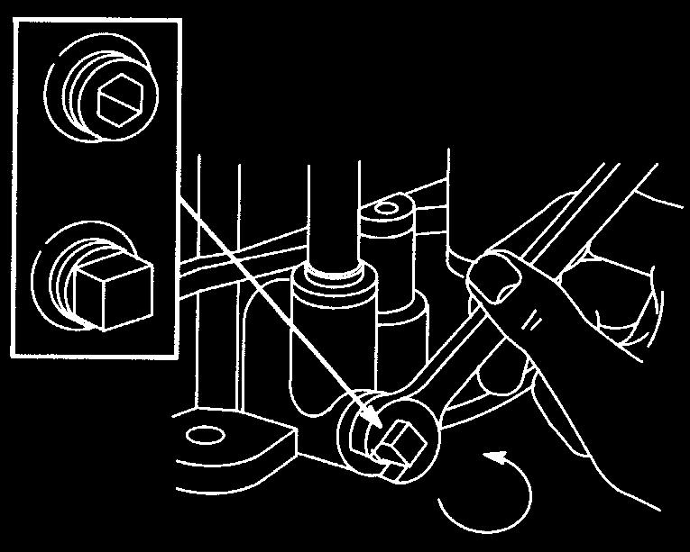
11 EN ENGLISH 1. Install the battery in the machine as shown below. 2. Place the machine outdoors or install an extraction device for the exhaust fumes. 3. Start the engine according to the instructions in the user guide. 4. Allow the engine to run continuously for 45 minutes. 5. Stop the engine. The battery will now be fully charged Charging using battery charger When charging using a battery charger, a battery charger with constant voltage must be used. Contact your dealer to purchase a battery charger with constant voltage. The battery can be damaged if a standard type battery charger is used Removal/Installation The battery is placed under the engine casing. See fig. 13. During removal/installation of the battery, the following applies regarding connection of the cables: During removal. First disconnect the black cable from the battery s negative terminal (-). Then disconnect the red cable from the battery s positive terminal (-). During installation. First connect the red cable to the battery s positive terminal (+). Then connect the black cable to the battery s negative terminal (-). If the cables are disconnected/connected in the wrong order, there is a risk of a short-circuit and damage to the battery. If the cables are interchanged, the generator and the battery will be damaged. Tighten the cables securely. Loose cables can cause a fire. The engine must never be driven with the battery disconnected. There is a risk of serious damage to the generator and the electrical system Cleaning If the battery terminals are coated with oxide, they should be cleaned. Clean the battery terminals with a wire brush and lubricate them with terminal grease. 5.9 Air filter The pre-filter (foam filter) must be cleaned/replaced after 25 hours of operation. The air filter (paper filter) must be cleaned/replaced after 100 hours of operation. NOTE! The filters should be cleaned/replaced more often if the machine operates on dusty ground. Remove/install the air filters as follows. 1. Clean carefully around the air filter cover. 2. Dismantle the air filter cover (14:R) by removing the two clamps. 3. Dismantle the filter assembly (14:S). The prefilter is placed over the air filter. Make sure that no dirt gets into the carburettor. Clean the air filter housing. 4. Clean the paper filter by tapping it gently against a flat surface. If the filter is very dirty, replace it. 5. Clean the pre-filter. If the filter is very dirty, replace it. 6. Assemble in the reverse order. Compressed air or petroleum-based solvents such as kerosene may not be used for cleaning the paper filter insert. This will damage the filter. Do not use compressed air for cleaning the paper filter insert. The paper filter insert must not be oiled Spark plug The spark plug(s) must be replaced every 200 hours of operation (=at every other basic service). Use the spark plug key supplied. Before disconnecting the spark plug, clean around its mounting. Spark plug: Champion RC12YC or equivalent.. Electrode distance: 0.75 mm Air intake (9:P) The engine is air-cooled. A blocked cooling system can damage the engine. Clean the engine s air intake after 50 hours of operation. More meticulous cleaning of the cooling system is carried out during each basic service Lubrication All lubrication points in accordance with the table below must be lubricated every 25 hours of operation as well as after every wash. Object Action Figure Rear shaft 3 grease nipples. (26:Z) Use a grease gun filled with universal grease. Pump until the grease emerges Steering cables Brush the cables clean with a wire brush. Lubricate with universal chain spray. - 50
12 ENGLISH EN Tensioning arms Control cables Lubricate the bearing points with an oil can when each control is activated. Ideally carried out by two people. Lubricate the cable ends with an oil can when each control is activated. Must be carried out by two people
13 EN ENGLISH 5.13 Fuses If any of the faults listed below occurs, replace the relevant fuse. The fuse(s) is located together with the battery under the engine casing.. Fault Fuse Figure The engine does not start or 10 A 25:Y starts and stops immediately. The battery is charged. All electrical functions are out of operation. The battery is charged. 20 A 24:X 25:X 6 PATENT - DESIGN REGISTRA- TION This machine or parts thereof is covered by the following patent and design registration: (SE), SE00/00250 (PCT), (SE), SE00/00577 (PCT), (SE), SE00/ (PCT), (SE), SE95/00525 (PCT), (US), (EPC) (SE), (DE), M (IT), (FR), (US). GGP reserves the right to make alterations to the product without prior notification. 52
14 GGP Sweden AB Box 1006 SE TRANÅS
STIGA PARK 4WD PRO 25 PRO 20 PRO 16. PRO Svan
 STIGA PARK 4WD PRO 25 PRO 20 PRO 16 PRO Svan BRUKSANVISNING KÄYTTÖOHJEET BRUGSANVISNING BRUKSANVISNING GEBRAUCHSANWEISUNG INSTRUCTIONS FOR USE MODE D EMPLOI GEBRUIKSAANWIJZING SV...8 FI...19 DA..30 NO.41
STIGA PARK PRO 18 PRO 16 PRESIDENT CLASSIC
 STIGA PARK PRO 18 PRO 16 PRESIDENT CLASSIC 8211-0211-06 7. Park Classic-President 11. 8. Park Pro16-Pro18 12. Park Classic-President 9. Park President 13. Park Pro16-Pro18 10. Park Pro16-Pro18 14. Park
STIGA TORNADO 51 S 51 SE PRO 51 S
 STIGA TORNADO 51 S 51 SE PRO 51 S 8211-0225-09 SVENSKA S 1 2 3 1. 2. ADD FULL FULL ADD ADD FULL 0,15 l. 3. LS 45 4. XTE 60 3x 5. LS 45 6. XTE 60 STOP I H 7. 8. 2 S SVENSKA 9. 10. 11. 12. LS 45 0,75 mm
STIGA DINO 45 EURO TORNADO
 STIGA DINO 45 EURO TORNADO 45 8211-3389-08 SVENSKA S 1. 2. 1 2 3 4 3. 4. FULL ADD ADD FULL 5. 6. STOP G G 7. 8. EURO 2 S SVENSKA 3 2 1 3x 9. 10. 0,76 mm 0,75 mm 11. 12. 40 Nm 13. 3 SVENSKA S 4 GB ENGLISH
STIGA PARK 4 WD 107 M 107 M HD 121 M. 125 Combi Pro B INSTRUCTIONS FOR USE. »HC P K»fl œoà «Œ EÀfl
 STIGA PARK 4 WD 107 M 107 M HD 121 M 125 Combi Pro B INSTRUCTIONS FOR USE»HC P K»fl œoà «Œ EÀfl 8211-0543-01 1 125 Combi Pro 2 125 Combi Pro 3 125 Combi Pro 121 M 107 M HD A B C B 4 125 Combi Pro 107 M
D 5b. 1. Park a. 6b. Park Park a. Park Park Park -1993
 STIGA PARK 121 M 1. Park -1993 5a. D 5b. 2. Park -1993 6a. Park -1999 6b. Park 2000- F G H 3. Park -1993 7. I I 4. Park -1993 8. 2 J 9. 13. 10. 14. Z X Y W V 11. 15. Denna produkt, eller delar därav, omfattas
STIGA COMPACT LINE SNOW REX SNOW BREEZE
 STIGA COMPACT LINE SNOW REX SNOW BREEZE BRUKSANVISNING KÄYTTÖOHJEET BRUGSANVISNING BRUKSANVISNING GEBRAUCHSANWEISUNG INSTRUCTIONS FOR USE MODE D EMPLOI ISTRUZIONI PER L USO INSTRUKCJA OBS UGI»HC P K»fl
Mountfield 480 R R Lawnmower Owner s Manual
 DEUTSCH D Mountfield 480 R - 550 R Lawnmower Owner s Manual 8211-0403-03 S SVENSKA 1 2 1 2 3 3 4 A B 5 6 7 8 2 SVENSKA 9 10 S 11 12 13 Briggs & Stratton 14 Honda ADD FULL 0,15 l. FULL/MAX ADD/MIN 15 Briggs
MTD OHV Series FORM NO B. jqa=mêççìåíë=^âíáéåöéëéääëåü~ñí= =p~~êäêωåâéå= =déêã~åó
 MTD OHV Series J15 FORM NO. 769-08890B jqa=mêççìåíë=^âíáéåöéëéääëåü~ñí= =p~~êäêωåâéå= =déêã~åó 4 11 19 27 35 43 51 58 65 72 79 87 96 104 112 119 126 134 141 148 155 162 171 179 188 197 206 213 221
Mountfield M Series Lawnmower Owner s Manual
 DEUTSCH D Mountfield M Series Lawnmower Owner s Manual 8211-0401-03 S SVENSKA B 1. 2. 3. 4. F D E 5. 6. 7. 2 SVENSKA S ADD FULL 0,15 l. 8. Briggs & Stratton 9. Honda FULL/MAX ADD/MIN 10. Briggs & Stratton
WARNING! Ensure that there are no naked flames around the product! Do not smoke while filling fuel and oil!
 Engine Oil and Fuel Engine Operation This product is equipped with a 4 stroke engine. Before operation you have to add proper fuel and engine oil. DO NOT MIXTURE THEM! 1. Place the product on a stable,
MTD OHV Series I15 FORM NO I. MTD Products Aktiengesellschaft Saarbrücken Germany
 MTD OHV Series I15 FORM NO. 769-01577I MTD Products Aktiengesellschaft Saarbrücken Germany 8 15 23 31 38 46 54 61 68 75 82 90 99 107 115 122 130 138 145 152 159 166 175 183 193 202 211 218 226 English
F B F B USER MANUAL. spac100. Dok: A-GB 0820
 F B 2 2 5 F B 2 5 0 USER MANUAL spac100 USE SWEPAC FB 225 / FB 250 are used to pack ballast under foundations, in connection with road building, in trenches, etc. On account of the forward/reverse function,
PowerSafe Two Wheel Tractors
 PowerSafe Two Wheel Tractors Manufactured by BCS S.p.A. Models 710 728 738 740 750 Operating Instructions Before commissioning the machine, read operating instructions and observe warning and safety instructions.
Edition Manual Chapter Page Workshop Manual, Stiga Park 4 Hydraulic system 8
 2008-05-19 Workshop Manual, Stiga Park 4 Hydraulic system 8 The charge pump (1) and the main pump (2) are integrated into one unit, the hydraulic pump (C) which is located separat in front of the engine.
Mountfield 480 R R Lawnmower Owner s Manual
 DEUTSCH Mountfield 480 R - 550 R Lawnmower Owner s Manual 8211-0403-01 D SVENSKA S B 1. 2. F D E 3. 4. 5. 6. 7. 8. 3 S SVENSKA ADD FULL 0,15 l. 9. 10. G I STOP 11. 12. 13. Y X 14. 0,75 mm 15. 16. 4 SVENSKA
HOFFMANN POWER PRODUCTS PARTS LIST 2014
 HOFFMANN POWER PRODUCTS PARTS LIST 2014 VIBRATORY PLATE COMPACTOR ALL PARTS ARE SUBJECT TO STANDARD HOFFMANN TERMS AND CONDITIONS OF SALE 2010 Replacement parts are not manufactured, sold or warranted
Side Discharge Chute Oil Filler & Dipstick Silencer/Exhaust
 1 SPECIFICATION Electric Start Engine - Size 6HP Engine speed 2850rpm Metal Deck Cutting width 550mm (22 ) Adjustable cutting height 7 Grass collection capacity 60L Gross weight 41Kg Fuel type Unleaded
Operator s manual. Please read the operator s manual carefully and make sure you understand the instructions before using the machine.
 8 8 Operator s manual Please read the operator s manual carefully and make sure you understand the instructions before using the machine. CONTENTS Contents CONTENTS Contents... 2 INTRODUCTION Dear Customer,...
Operator s manual. Please read the operator s manual carefully and make sure you understand the instructions before using the machine.
 Operator s manual Please read the operator s manual carefully and make sure you understand the instructions before using the machine. FR 2213 RA FR 2215 MA FR 2215 MA 4X4 CONTENTS Contents CONTENTS Contents...
Items Vehicles with 4G63 engine Vehicles with 4D56 engine. Type 4-speed full automatic 4-speed full automatic. 2nd rd
 23-2 AUTOMATIC TRANSMISSION General Information/ Service Specifications GENERAL INFORMATION 23100010141 Items Vehicles with 4G63 engine Vehicles with 4D56 engine Transmission model R4AW2-6 V4AW2-6 Type
Operator s manual. Rider 15Ts AWD. Please read the operator s manual carefully and make sure you understand the instructions before using the machine.
 Rider 15T Operator s manual Rider 15T AWD Rider 15Ts AWD Please read the operator s manual carefully and make sure you understand the instructions before using the machine. English CONTENTS Contents CONTENTS
North Dakota State University Grounds Maintenance Equipment
 North Dakota State University Grounds Maintenance Equipment I. Introduction Grounds maintenance equipment is an important part of the work activities on NDSU campus. They can make grounds maintenance jobs
GENERATOR MODEL NO: FG3005 OPERATION & MAINTENANCE INSTRUCTIONS PART NO: LS0413
 GENERATOR MODEL NO: FG3005 PART NO: 8857707 OPERATION & MAINTENANCE INSTRUCTIONS LS0413 INTRODUCTION Thank you for purchasing this CLARKE Generator. Before attempting to use this product, please read this
FB 160 FB 175 FB 235 FB 255 FB 265 USER MANUAL IN ORIGINAL
 FB 160 FB 175 FB 235 FB 255 FB 265 USER MANUAL IN ORIGINAL 2 USE SWEPAC FB160 / FB 175 / FB 235 / FB 255 / FB 265 are used to pack ballast under foundations, in connection with road building, in trenches,
1P88F-1 1P90F-1 1P92F-1. Owner's Manuel
 1P88F-1 1P90F-1 1P92F-1 Owner's Manuel EN 1 TABLE OF CONTENTS 1. General information... 1 2. Safety regulations... 1 3. Components and controls... 2 4. What you need to know... 3 5. Standards of use...
Operator s manual. Please read the operator s manual carefully and make sure you understand the instructions before using the machine.
 FR2312 MA Operator s manual Please read the operator s manual carefully and make sure you understand the instructions before using the machine. FR2312 M CONTENTS Contents CONTENTS Contents... 2 INTRODUCTION
PF-4000, PF-4010, PF-4210 MULTI-PURPOSE ENGINE
 PF-4000, PF-4010, PF-4210 MULTI-PURPOSE ENGINE Date 09-26-01 Supplier To The Outdoor Power Equipment Industry ISM, Inc. 1028 4 th Street SW Auburn, WA 98001 Phone: (253) 333-1200 Fax: (253) 333-1212 WWW.TANAKA-USA.COM
Operator s manual. Rider 316TXs AWD
 Operator s manual Rider 316T Rider 316T AWD Rider 316Ts AWD Rider 316Ts AWD Please read the operator s manual carefully and make sure you understand the instructions before using the machine. English CONTENTS
Owner s/operator s Manual
 Water Pump MP2533E2 Owner s/operator s Manual Completely read and understand this manual before using this product. Foreword This Owner s/ Operator s Manual is designed to familiarize the operator with
GENERATOR MODEL NO: FG3000 OPERATION & MAINTENANCE INSTRUCTIONS PART NO: LS0609
 GENERATOR MODEL NO: FG3000 PART NO: 8857700 OPERATION & MAINTENANCE INSTRUCTIONS LS0609 INTRODUCTION Thank you for purchasing this CLARKE Generator. Before attempting to use this product, please read this
Operator s manual. Please read the operator s manual carefully and make sure you understand the instructions before using the machine.
 3 3 8 8 Operator s manual Please read the operator s manual carefully and make sure you understand the instructions before using the machine. FR 2318 FA FR 2318 FA 44 CONTENTS Contents CONTENTS Contents...
Operator s manual. Please read the operator s manual carefully and make sure you understand the instructions before using the machine.
 FR 2211R FR 2211M FR 2213 MA FR2216 MA 44 Operator s manual Please read the operator s manual carefully and make sure you understand the instructions before using the machine. CONTENTS Contents CONTENTS
R 418Ts R 418Ts AWD Please read the operator s manual carefully and make sure you understand the instructions before using the machine.
 Operator s manual R 418Ts R 418Ts AWD Please read the operator s manual carefully and make sure you understand the instructions before using the machine. English CONTENTS Contents CONTENTS Contents...
Operator s manual. Please read the operator s manual carefully and make sure you understand the instructions before using the machine.
 FR 2311 M FR 2312 MA Operator s manual Please read the operator s manual carefully and make sure you understand the instructions before using the machine. CONTENTS Contents CONTENTS Contents... 2 INTRODUCTION
GENERATOR MODEL NO: FG2500 OPERATION & MAINTENANCE INSTRUCTIONS PART NO: LS0114
 GENERATOR MODEL NO: FG2500 PART NO: 8857727 OPERATION & MAINTENANCE INSTRUCTIONS LS0114 INTRODUCTION Thank you for purchasing this CLARKE Generator. Before attempting to use this product, please read this
Operating and Assembly Manual
 Model 1080 Operating and Assembly Manual Midwest Equipment Manufacturing, Inc. 5225 Serum Plant Road Thorntown, IN 46071 08-02-16 SAFETY RULES Remember, any power equipment can cause injury if operated
FB 300 FB 450 FB 700 USER MANUAL
 FB 300 FB 450 FB 700 USER MANUAL 2 USE SWEPAC FB 300 / FB 450 / FB 700 are used to pack ballast under foundations, in connection with road building, in trenches, etc. On account of the forward/reverse
LAWN MOWER OWNER S MANUAL
 LAWN MOWER OWNER S MANUAL Woodies SKU: 1153279 & 1153280 CAUTION: Read and follow all Safety Rules and Instructions before operating this equipment Thank you for choosing our Gasoline Lawnmower. 1 To ensure
5.5KVA GENERATOR MODEL NO: PG6500DVES OPERATION & MAINTENANCE INSTRUCTIONS PART NO: LS0616
 5.5KVA GENERATOR MODEL NO: PG6500DVES PART NO: 8857810 OPERATION & MAINTENANCE INSTRUCTIONS LS0616 INTRODUCTION Thank you for purchasing this CLARKE 5.5KVA Generator. Before attempting to use this product,
1.CONTENTS 1. Contents Control location Before riding Safe riding Driving Use genuine spare parts Use
 1.CONTENTS 1. Contents... 1 2. Control location... 3 3. Before riding... 4 4. Safe riding... 4 5. Driving... 5 6. Use genuine spare parts... 5 7. Use of each component... 6 Gauges... 6 Operation of ignition
jqa=mêççìåíë=^âíáéåöéëéääëåü~ñí= =p~~êäê ÅâÉå= =déêã~åó
 jqa=mêççìåíë=^âíáéåöéëéääëåü~ñí= =p~~êäê ÅâÉå= =déêã~åó 1 Max. Min. Q R 1 2 1. 4. 1 2. 1 2 3 3. 5. 1 4 1 6 8. 8. 6. 5 7. 9. 1 2 English....................... 8 (Original operating instructions) Français......................
Operator s manual. Please read the operator s manual carefully and make sure you understand the instructions before using the machine.
 R 422Ts Operator s manual R 422Ts AWD Please read the operator s manual carefully and make sure you understand the instructions before using the machine. English CONTENTS Contents CONTENTS Contents...
Mountfield. Princess Lawnmower Owner s Manual
 DEUTSCH D Princess Lawnmower Owner s Manual 8211-0408-01 GB ENGLISH SAFETY INSTRUCTIONS SYMBOLS The following symbols can be found on the machine to remind you of the care and attention that are required
PR 17 PR 17 AWD PF 21 PF 21 AWD Please read the operator s manual carefully and make sure you understand the instructions before using the machine.
 Operator s manual PR 17 PR 17 AWD PF 21 PF 21 AWD Please read the operator s manual carefully and make sure you understand the instructions before using the machine. English CONTENTS Contents CONTENTS
1200W INVERTER GENERATOR
 1200W INVERTER GENERATOR MODEL NO: IG1200 PART NO: 8877070 OPERATION & MAINTENANCE INSTRUCTIONS LS0117 INTRODUCTION Thank you for purchasing this CLARKE 1200W Inverter Generator. Before attempting to use
Workshop manual Rider ProFlex 18 Rider ProFlex 21 English
 Workshop manual Rider ProFlex 18 Rider ProFlex 21 English Workshop manual for Rider ProFlex 18 and ProFlex 21 Contents Contents...1 Safety Instructions...2 General Instructions...2 Special Instructions...2
TC07 TURF CUTTER Operating Instructions
 TC07 TURF CUTTER Operating Instructions Before commissioning the machine, read operating instructions and observe warning and safety instructions. Tracmaster Ltd CAMON TC07 Turf Cutter Manufacturer Details
Operator s manual Rider 155. Please read these instructions carefully and make sure you understand them before using the machine.
 Operator s manual Rider 155 Please read these instructions carefully and make sure you understand them before using the machine. English CONTENTS Operator s Manual for Rider 155 Introduction... 2 Driving
INSTRUCTION MANUAL. LAWN MOWER LazerMulch LMS400 CONSUMER HELPLINE PLEASE READ THE INSTRUCTIONS IN THIS MANUAL BEFORE OPERATION.
 INSTRUCTION MANUAL LAWN MOWER LazerMulch LMS400 CONSUMER HELPLINE 1800 466 068 PLEASE READ THE INSTRUCTIONS IN THIS MANUAL BEFORE OPERATION. INSTRUCTION MANUAL LMS400 LAWN MOWER What you get with your
Water pump Owner's Manual
 Water pump Owner's Manual Safety Precautions I. General Safeguards Please read this operation manual to have a thorough understanding of the content there before use the product. Failure to do so may lead
Workshop manual. Rider ProFlex 21 II. English.
 Workshop manual Rider ProFlex 21 II English Svenska 31 Workshop Manual for the Rider ProFlex 21 II Contents Contents...1 Safety Instructions...2 General Instructions...2 Special Instructions...2 Special
INSTRUCTION MANUAL GASOLINE BRUSH CUTTER TR L. 42.7cc. 1.3 kw. 450 mm. Note : Read and carefully before using this machine
 INSTRUCTION MANUAL GASOLINE BRUSH CUTTER TR15142 Note : Read and carefully before using this machine 42.7cc 1.3 kw 450 mm 18" 0.70 L MANUAL SAFETY SYMBOLS AND IMPORTANT INFORMATION This symbol accompanied
M. E. Y. EQUIPMENT MOWER MANUAL
 M. E. Y. EQUIPMENT MOWER MANUAL 200 COLLIER ROAD, BAYSWATER. WESTERN AUSTRALIA 6053 TELEPHONE (08) 9370 1110, FACSIMILE (08) 9370 2566 Web Site: www.mey.com.au Email: info@mey.com.au INTRODUCTION The technical
Operator s manual R 214TC. Please read the operator s manual carefully and make sure you understand the instructions before using the machine.
 Operator s manual R 214TC Please read the operator s manual carefully and make sure you understand the instructions before using the machine. English KEY TO SYMBOLS Symbols These symbols are on the machine
Rider Pro 15. Operator s manual Please read these instructions carefully and make sure you understand them before using the machine.
 Rider Pro 15 Operator s manual Please read these instructions carefully and make sure you understand them before using the machine. 101 91 34-26 CONTENTS Operator s Manual for Rider Pro 15 Introduction...
Operator's Manual. Please read these instructions carefully and make sure you understand them before using the machine.
 Operator's Manual Please read these instructions carefully and make sure you understand them before using the machine. TABLE OF CONTENTS Operator s manual for FR 2111, FR 2111 M, FR 2113 A, FR 2113 MA,
Wheel Horse. 44 Snowthrower. for 5xi Lawn and Garden Tractors. Model No & Up. Operator s Manual
 FORM NO. 8 Rev A Wheel Horse Snowthrower for 5xi Lawn and Garden Tractors Model No. 7966 890050 & Up Operator s Manual IMPORTANT: Read this manual, and your tractor manual, carefully. They contain information
Operator's Manual. Please read these instructions carefully and make sure you understand them before using the machine.
 Operator's Manual Please read these instructions carefully and make sure you understand them before using the machine. TABLE OF CONTENTS Operator s manual for FR 2111, FR 2111 M, FR 2113 MA, FR 2115 MA,
QT INSTRUCTION MANUAL
 QT INSTRUCTION MANUAL PLEASE READ BEFORE USE Distributed by Qpod Motor Company Tel: 01404 850545 Fax: 01404 851110 www.qpod.co.uk Contents Pg 3 Servicing and Warranty Pg 4 Serial Numbers / Vehicle Keys
Maintenance of Pleasureboat Diesel Engine GM Series
 Maintenance of Pleasureboat Diesel Engine GM Series.Safety Precaution for Inspection )Battery Fluid Battery fluid is diluted sulfuric acid. It can blind you if it gets in your eyes, or burn your skin.
Wheel Horse. 523Dxi Tractor. Model No & Up. Operator s Manual
 FORM NO. 332 988 Wheel Horse 523Dxi Tractor Model No. 73590 990000 & Up Operator s Manual IMPORTANT: Read this manual carefully. It contains information about your safety and the safety of others. Also
SECTION 8 2 DO IT YOURSELF MAINTENANCE. Chassis
 DO IT YOURSELF MAINTENANCE Chassis SECTION 8 2 Checking the coolant level of the traction motor................ 184 Checking the radiator....................................... 185 Checking brake fluid........................................
Wheel Horse. 42 Mower. for Lawn and Garden Tractors. Model No & Up. Operator s Manual
 FORM NO. 9 559 Rev A Wheel Horse 4 Mower for Lawn and Garden Tractors Model No. 78 890000 & Up Operator s Manual IMPORTANT: Read this manual carefully. It contains information about your safety and the
Operating Instructions Gasoline Hedge Trimmer. After Sales Support. TEL: WEB: BG-PH2250 N16188
 Operating Instructions Gasoline Hedge Trimmer After Sales Support TEL: 1300 130 579 WEB: www.rossmac.com N16188 BG-PH2250 Gasoline Hedge Trimmer What your 1 year warranty means Great care has gone into
GRAVELY CONVERTIBLE 10 CONVERTIBLE 12 OWNERS MANUAL
 A SAFETY MESSAGE The product for which you have requested information or replacement parts is not a current product. The replacement models incorporate product designs, safety features, safety instruction
Edition Manual Chapter Page Workshop Manual, Stiga Park 5 Belts 11
 2008-05-19 Workshop Manual, Stiga Park 5 Belts 11 Pro 20 1. Dismantle the belts A and B as described above. 2. Block up the rear frame and remove the right rear wheel. Clean carefully the insex hole in
RedGum GP160 Splitter. Owner s Manual
 RedGum GP160 Splitter Owner s Manual Product Description & Intended Purpose: This Log Splitter / Wood Splitter is an outdoor product that splits wood logs for use as fuel in a fireplace or a woodstove.
Finishing Mower Estate 72
 Finishing Mower Estate 72 Owners/Operators Manual & Spare Parts List Issue Date: October 2011 1 Introduction Your FIELDMASTER Estate 72 Finishing Mower has been designed to do a range of work to your satisfaction.
WARNING: Read these instructions before using the machine GENERATOR MODEL NO: IG3500F PART NO: OPERATION & MAINTENANCE INSTRUCTIONS
 WARNING: Read these instructions before using the machine GENERATOR MODEL NO: IG3500F PART NO: 8877100 OPERATION & MAINTENANCE INSTRUCTIONS ORIGINAL INSTRUCTIONS LS0217 INTRODUCTION Thank you for purchasing
TC07 Turf Cutter Operating Instructions
 TC07 Turf Cutter Operating Instructions Before commissioning the machine, read operating instructions and observe warning and safety instructions. Manufacturer Details Tracmaster Ltd Sovereign Centre
48 Side Discharge Mower
 FORM NO. 9 7GB Wheel Horse 48 Side Discharge Mower for Lawn & Garden Tractors Model No. 7868 790000 & Up Operator s Manual IMPORTANT: Read this manual carefully. It contains information about your safety
LWA STIGA DINO. Model:... Type:... (Year)... S/N...
... S/N...") STIGA DINO Model:................ Type:........... (Year)....... S/N................ LWA db BRUKSANVISNING KÄYTTÖOHJEET BRUGSANVISNING BRUKSANVISNING GEBRAUCHSANWEISUNG INSTRUCTIONS FOR USE MODE D EMPLOI
STIGA DINO Model:................ Type:........... (Year)....... S/N................ LWA db BRUKSANVISNING KÄYTTÖOHJEET BRUGSANVISNING BRUKSANVISNING GEBRAUCHSANWEISUNG INSTRUCTIONS FOR USE MODE D EMPLOI
Wheel Horse. 48 Mower. for Lawn and Garden Tractors. Model No & Up. Operator s Manual
 FORM NO. 5 Wheel Horse 48 Mower for Lawn and Garden Tractors Model No. 786 990000 & Up Operator s Manual IMPORTANT: Read this manual carefully. It contains information about your safety and the safety
Cordless Screwdriver
 ENGLISH Cordless Screwdriver MODEL 6796D MODEL 6796FD MODEL 6797D MODEL 6797FD MODEL 6798D MODEL 6798FD 00260 I N S T R U C T I O N M A N U A L WARNING: For your personal safety, READ and UNDERSTAND before
Owner s Manual. Mortar / Plaster Mixer. Models M785 M1000 M1200
 Owner s Manual Mortar / Plaster Mixer Models M785 M1000 M1200 Tiger Equipment LLC. 15 Byrd Lane Rocky Mount, VA 24151 Tel: 540-489-7777 Fax: 540-489-7778 www.tigerequip.com 1. PREFACE This manual contains
Wheel Horse. 520Lxi Tractor. Model No & UP. Operator s Manual
 FORM NO. 33 980 Wheel Horse 50Lxi Tractor Model No. 73580 990000 & UP Operator s Manual IMPORTANT: Read this manual carefully. It contains information about your safety and the safety of others. Also become
DIAMOND CONCRETE SAW MODEL CC1800XL P R O D U C T S OPERATOR S MANUAL. February Part #
 DIAMOND P R O D U C T S OPERATOR S MANUAL CONCRETE SAW MODEL CC1800XL February 2007 Part #1801038 Intentionally Blank GENERAL SAFETY WARNINGS AND PRECAUTIONS PERSONAL SAFETY Read and understand all operating
Recovery instructions
 Recovery instructions Contents Contents General... 2 Chassis lifting points General chassis lifting points... 3 Recovery/towing Preparatory work... 6 Recovery Recovery from a ditch... 8 Lifting an air
GROUNDSMASTER. 52 Recycler. for 120 Traction Unit. Model No & UP. Operator s Manual
 FORM NO. 8-980 Rev A GROUNDSMASTER 5 Recycler for 0 Traction Unit Model No. 077 79000 & UP Operator s Manual IMPORTANT: Read this manual carefully. It contains information about your safety and the safety
TRE 0701 TRE 0702 TRE 0801
 TRE 070 TRE 0702 TRE 080 FR EN DE IT NL ES PT EL TR MK NO SV DA FI CS PL HU RU HR SL MANUEL D UTILISATION OPERATOR S MANUAL GEBRAUCHSANWEISUNG MANUALE DI ISTRUZIONI GEBRUIKERSHANDLEIDING MANUAL DE INSTRUCCIONES
1100W PORTABLE GENERATOR
 1100W PORTABLE GENERATOR MODEL NO: G1200 PART NO: 8010110 OPERATION & MAINTENANCE INSTRUCTIONS LS0312 INTRODUCTION Thank you for purchasing this CLARKE 1100W Portable Generator. Before attempting to use
Model 560 Model 580. Operating and Assembly Manual. Midwest Equipment Mfg Serum Plant Road Thorntown, IN 46071
 Model 560 Model 580 Operating and Assembly Manual Midwest Equipment Mfg. 5225 Serum Plant Road Thorntown, IN 46071 10/14/2018 SAFETY RULES Remember, any power equipment can cause injury if operated improperly
Racing NAVODILO ZA UPORABO USER'S MANUAL
 Racing NAVODILO ZA UPORABO USER'S MANUAL TOMOS USER'S MANUAL YOUNGST'R YOUNGST'R FULL RACING 45 1 CONTENTS Warnings 3 Riding Safety Tips 3 Technical Specification 4-5 Technical Description 6-9 Vehicle
Repair Manual 11/99 PS-34. Page 1
 Repair Manual /99 PS-4 Page Table of contents Index Technical Data page Special tools 4 Repair instructions, general 0 Chain brake 6 0 Centrifugal clutch 8 0 Oil pump 9-04 Ignition system - 0 Starting
Light condition and operation Windshield glass condition Wiper blade condition Paint condition and corrosion Fluid leaks Door and hood lock condition
 GENERAL CHECKS Engine Compartment The following should be checked regularly: Engine oil level and condition Transmission fluid level and condition Brake fluid level Clutch fluid level Engine coolant level
3KVA DUAL VOLTAGE GENERATOR MODEL NO: PG3800DV
 3KVA DUAL VOLTAGE GENERATOR MODEL NO: PG3800DV PART NO: 8857815 OPERATION & MAINTENANCE INSTRUCTIONS LS1016 INTRODUCTION Thank you for purchasing this CLARKE 3KVA Dual Voltage Generator. Before attempting
OWNER S / OPERATOR S MANUAL
 OWNER S / OPERATOR S MANUAL SAFETY PAGE 1 RECOGNIZE SAFETY INFORMATION This is the safety-alert symbol. When you see this symbol in this manual or on your EdgeMasterTM, be alert to the potential for personal
by Eder Maschinenbau GmbH
 by Eder Maschinenbau GmbH GB Owner's Manual Contents Symbols 3 Technical data 3 Field of use 4 Safety regulations 4 Fuel and filling the tank 5 Engine oil 5 Slings and rope guide 5 Safety instruction for
Rider 115C Rider 120C
 Operator s manual Rider 115C Rider 120C Please read the operator s manual carefully and make sure you understand the instructions before using the machine. English CONTENTS Contents CONTENTS Contents...
720W PORTABLE GENERATOR
 720W PORTABLE GENERATOR MODEL NO: G720 PART NO: 8857800 OPERATION & MAINTENANCE INSTRUCTIONS LS0214 INTRODUCTION Thank you for purchasing this CLARKE 720W Portable Generator Before attempting to use this
Rider 850 HST Rider 970 HST
 RIDER 970 RIDER 850 RIDER 850 Rider 850 HST Rider 970 HST Operator s manual Please read these instructions carefully and make sure you understand them before using the machine. 101 89 36-26 CONTENTS Operator
Mountfield El 33 Lawnmower Owner s Manual
 DEUTSCH D Mountfield El 33 Lawnmower Owner s Manual 811-0400-01 S SVENSKA 4 1 3 1 = 0 mm = 30 mm 3 = 40 mm 4 = 50 mm 1 130 mm 4 3 3. 160 mm 1 A C B 1. 4. 1 8 4 3 5 9. SVENSKA S 5. 6.. 3 STOP SAFETY INSTRUCTIONS
SAFETY AND OPERATION REQUIREMENTS CHART
 OPERATION, MAINTENANCE and SAFETY MANUAL MB16 and MTB16 Scoot-Crete Power Buggies IMPORTANT MACHINE SERVICE NOTES This manual covers the safety, operation and adjustment procedures for the Miller Scoot-Crete
FR2315 MA. Operator s manual. Please read the operator s manual carefully and make sure you understand the instructions before using the machine.
 FR2315 MA Operator s manual Please read the operator s manual carefully and make sure you understand the instructions before using the machine. CONTENTS Contents CONTENTS Contents... 2 INTRODUCTION Dear
CONTENTS. Contents. 2 English
 Rider 15V2 Operator s manual Rider 15V2 AWD Rider 15V2s AWD Please read the operator s manual carefully and make sure you understand the instructions before using the machine. English CONTENTS Contents
KING CANADA 950W PORTABLE GENERATOR MODEL: KCG-951G INSTRUCTION MANUAL COPYRIGHT 2011 ALL RIGHTS RESERVED BY KING CANADA TOOLS INC.
 KING CANADA 950W PORTABLE GENERATOR MODEL: KCG-951G INSTRUCTION MANUAL COPYRIGHT 2011 ALL RIGHTS RESERVED BY KING CANADA TOOLS INC. WARRANTY & SERVICE INFORMATION 1-YEAR LIMITED WARRANTY FOR THIS 950W
MOTORINI GP 50. User s Manual.
 MOTORINI GP 50 User s Manual www.motorini.co.uk Dear user: Thank you for choosing to buy a Motorini GP 50 This manual provides the correct operation and maintenance methods for safe riding and maintaining
Worldlawn Power Equipment, Inc. Industrial Park 2415 Ashland Ave. Beatrice, NE Toll Free Number:
 Operator s Manual R WYZ48/52/60CS BAGGER Worldlawn Power Equipment, Inc. Industrial Park 2415 Ashland Ave. Beatrice, NE 68310 Toll Free Number: 1-800-267-4255 OPERATOR S MANUAL This catcher manual is for
Engine oil. Introduction. Warning and indicator lights WARNING
 Engine oil Introduction In this section you ll find information about: Warning and indicator lights Engine oil specifications Engine oil capacities Checking the engine oil level and adding oil Engine oil