PH: (925)
|
|
|
- Alexander Smith
- 5 years ago
- Views:
Transcription


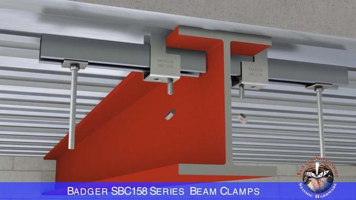
1 SBC BEAM CLAMPS


2 PH: (925) SERIES BEAM CLAMPS IBC, ASCE, ANSI/MSS SP-58, ANSI/FM , FM , FM , CBC / OSHPD AND NFPA-13 CODE AND STANDARD COMPLIANT The ULTIMATE Strut & Single Hanger VISUAL INSPECTION COMPLIANT WORKS ON FIRE PROOFED BEAMS & SEISMIC COMPLIANT 50% OR MORE LABOR SAVINGS IDEAL FOR STRUT CEILING GRIDS


3 LINK TO VIDEO


4 LINK TO VIDEO
 -C See Fitment Detail (-C-FRD) L See Fitment Detail (L-FRD) ~ - BEAM CLAMPS ~ FITS")


5 SERIES BEAM CLAMPS Cost Effective - CODE Compliance - No Known Equal -C L L-C STRUT BEAM CLAMP See Fitment Detail (-FRD) -C See Fitment Detail (-C-FRD) L See Fitment Detail (L-FRD) ~ - BEAM CLAMPS ~ FITS ROD TREADED SIZES 3/8" 1/2" 5/8" 3/8" 1/2" 5/8" 3/4" **FITS STRUT SINGLE SIZES 13/16"x 1-5/8" 1"x 1-5/8" 1-3/8"x 1-5/8" 1-5/8"x 1-5/8" 2-7/16"x 1-5/8" 13/16"x 1-5/8" 1"x 1-5/8" 1-3/8"x 1-5/8" 1-5/8"x 1-5/8" 2-7/16"x 1-5/8" 13/16"x 1-5/8" 1"x 1-5/8" 1-3/8"x 1-5/8" 1-5/8"x 1-5/8" 2-7/16"x 1-5/8" 3-1/4"x 1-5/8" **FITS BACK- TO- BACK STRUT SIZES 1-5/8"x 1-5/8" 2"x 1-5/8" 2-3/4"x 1-5/8" Used For Connection Of RIGID & CABLE Seismic Bracing To Steel Beams & Joists. 1-5/8"x 1-5/8" 2"x 1-5/8" 2-3/4"x 1-5/8" 3-1/4"x 1-5/8" QUANTITY PER BOX 20 pcs. 20 pcs. WEIGHT PER lbs. 175 lbs. MFG. Suggested LIST PRICE $4.95 each 20 pcs. 153 lbs. $10.65 each $7.95 each 3/8" 1-5/8"x 1-5/8" L-C 20 pcs. 188 lbs. $ /2" 2"x 1-5/8" each See Fitment Detail 5/8" 2-3/4"x 1-5/8" (L-C-FRD) 3/4" 3-1/4"x 1-5/8" Contact: Sales@NoDrillHangers.com Information subject to change without notice. **Strut size fitment varies per beam or joist flange flange thickness. Contact: Sales@NoDrillHangers.com For Buy America Compliance / Buy American Compliance, Special Order Requirements.
6 SERIES BEAM CLAMPS Cost Effective - CODE Compliance - No Known Equal -C L L-C Stocking Master Distributors: Southern California Jobsite Supply Co. Brad Lawhorn (714) Pacific Southwest Sales Carl Curtis (213) ACME Construction Supply Co. Jamie Shaughnessy (714) Stocking Master Distributors: Northern California Fluid Gauge Co. / Force Support Services Tim Lindfelt, P.E. (415) ACME Construction Supply Co. Jamie Shaughnessy (714) Stocking Master Distributors: Washington & Oregon ACME Construction Supply Co. James Punzel (253) Stocking Master Distributors: National E-Commerce MahannCo Stocking Master Distributors: CANADA Cascadia M8 Seismic Terry Richards (778)
7 ~ SBC GENERAL NOTICE ~ Neither NUSIG nor is responsible for engineering or detailing the use of NUSIG, Industries and/or others products and components for a specific project and/or application. All such engineering is to be performed by an engineer, retained by others, who is licensed to perform the necessary engineering, and who is insured to provide these Responsible Engineer engineering services. All design submittals specifying NUSIG / products and components must be sealed and signed by the Responsible Engineer, and submitted for review and approval to the project S.E.O.R. (Structural Engineer Of Record). Laboratory testing (even that recognized by building codes and standards) is not necessarily indicative of actual project specific application usage conditions. The usage, design, engineering, installation and inspection of construction component assemblies (both seismic and non seismic) shall take into account the capacity limits of the weakest components and conditions within the overall assembly, including but not limited to the building structure, threaded rod compression with or (without) rod stiffeners, prying and eccentricity interactions, etc. Such shall be the responsibility of non NUSIG / others. NUSIG / documents are subject to change without notice or responsibility. NUSIG / Industries products, components and documents are for interior use. It is the responsibility of the user to qualify that they are using the most current NUSIG / documents. Prior to usage read (Back Of Strut Opening Notice), (Fire Proofed Beam Notice) and (Beam Bending Notice). LIMITATION OF LIABILITY To the fullest extent permissible by law, NUSIG,, and their respective owners, officers, directors, employees, agents and representatives (collective, the Parties ) excludes all liability except liability that is directly attributable to the willful negligence of the Parties. Should the Parties be held liable, under any theory, the aggregate liability of all of them is limited to the total purchase price of the Parties products that caused the injury or loss. In addition to the foregoing, THE PARTIES ARE IN NO EVENT LIABLE FOR ANY LOSS OF BUSINESS OR PROFITS, LOSS OF USE, LOSS OF OPPORTUNITIES, DOWNTIME OR DELAY, LABOR, REPAIR OR MATERIAL COST OR ANY OTHER SIMILAR OR DISSIMILAR, INCIDENTAL OR CONSEQUENTIAL LOSS OR DAMAGE INCURRED BY BUYER. By purchasing the Parties products, you agree to this limitation of liability on your behalf, and on behalf of the person or organization purchasing the products. WARRANTY NUSIG and/or products are warranted to be free from defects in material and workmanship at the time of shipment. NO OTHER WARRANTY, WHETHER EXPRESS OR IMPLIED (INCLUDING ANY WARRANTY OF MERCHANTABILITY OR FITNESS FOR A PARTICULAR PURPOSE), SHALL EXIST IN CONNECTION WITH THE SALE OR USE OF ANY NUSIG AND/OR PRODUCTS. Products claimed to be defective or nonconforming must be identified in writing and returned (within 30 calendar days) to NUSIG / for inspection. Notice of a warranty claim within this 30 day period is a condition precedent to this Warranty. In no event shall NUSIG / be responsible if the products have been improperly stored, improperly used, abused or misused. NUSIG / Industries will, at its option, either repair or replace defective or nonconforming products for which it is responsible or return the purchase price to the BUYER. THE FOREGOING STATES BUYER S EXCLUSIVE REMEDY FOR ANY BREACH OF THE NUSIG AND/OR WARRANTY AND FOR ANY CLAIM, WHETHER SOUNDING IN CONTRACT, TORT OR NEGLIGENCE, FOR LOSS OR INJURY CAUSED BY THE SALE OR USE OF ANY NUSIG AND/OR PRODUCT(S). WARNING The improper use, misuse and/or misapplication of these documents and/or NUSIG / products may cause product malfunction, property damage, bodily injury and death. CONTINUED NEXT PAGE
8 ~ SBC GENERAL NOTICE ~ Seismic tension and compression capacities where derived from ANSI/FM testing performed by Factory Mutual. ANSI/FM testing meets the requirements of FM and FM Seismic (LRFD) tension and compression profiles were determined using the data provided by Factory Mutual. Listed (LRFD) seismic capacities can be converted to (ASD) capacities by dividing by (1.4). Seismic capacities listed within these details only take into consideration the identified beam clamp and/or strut member. Capacities for all other items, including but not limited to, steel beams and joist, threaded rods, pipe / conduit clamps, etc., are not taken into consideration. The following controls and parameters where used to develop listed seismic tension and compression capacities. a.) ANSI/FM b.) strut deflection at applied load = 1 inch. c.) strut (LRFD) design capacity based on 70% of minimum material yield stress. d.) Section properties per detail identified strut manufacture literature. Gravity tension capacities were determined through testing performed on a calibrated universal tensile machine at Anvil International s Research & Development facility in North Kingstown, RI. Test data was analyzed in accordance with ANSI/MSS SP-58. Gravity tension capacities listed within these details only take into consideration the identified beam clamp and/or strut member. Threaded rod tension capacities are based on ANSI/MSS SP-58, Table 3. Capacities for all other items, including but not limited to, steel beams and joist, pipe / conduit clamps, etc., are not taken into consideration. The follow controls and parameters where used to develop listed MSS SP-58 gravity tension capacities. e.) Tested capacities by the derived safety factors listed within ANSI/MSS SP-58. capacities not to exceed 67% of the yield load. f.) strut design capacity based on 12,900 psi allowable material stress within ANSI/MSS SP-58, referenced by ASME B31.1. g.) Section properties per detail identified strut manufacture literature. Allowable stresses were derived from ANSI/MSS SP-58 and ASME B31.1 and apply a minimum 3.5 times safety factor to the design. The Metal Framing Manufactures Association s (MFMA) 25,000 psi allowable stress applies a minimum 1.8 times safety factor and exceeds 75% of the material s minimum yield. MFMA s allowable design stress does not meet the design requirements of ANSI/MSS SP-58 and therefore was not used to determine listed gravity tension capacities. For compliance with NFPA-13 (Safety Factor = 5 plus 250 lbs.) gravity hanger building attached component design requirement, take the detail applicable ANSI/MSS SP-58 capacity and multiply it by (3.5) and match it to an equal or lesser Minimum Check Load identified below. 1" & 1-1/4" pipe size /2" pipe size " pipe size /2" pipe size " pipe size /2" pipe size " pipe size " pipe size " pipe size " pipe size " pipe size " pipe size lbs Minimum Check Load. 520 lbs Minimum Check Load. 635 lbs Minimum Check Load. 940 lbs Minimum Check Load. 1,060 lbs Minimum Check Load. 1,255 lbs Minimum Check Load. 1,500 lbs Minimum Check Load. 2,000 lbs Minimum Check Load. 2,650 lbs Minimum Check Load. 4,050 lbs Minimum Check Load. 5,855 lbs Minimum Check Load. 7,900 lbs Minimum Check Load. Capacities per NFPA-13 maximum hanger spans using schedule 40 steel pipe full of water and a (Safety Factor = 5 plus 250 lbs.). Project specific hanger spacing and pipe schedule capacities can be engineered provided a (Safety Factor = 5 plus 250 lbs.) is maintained. ANVIL PRODUCTS Additional information on Anvil products, including warranties can be found at END
9 BACK OF STRUT ~ OPENINGS NOTICE ~ TOP VIEW Side Of Strut Member (9/16") Inch Diameter Hole Opening Center Spaced (1-7/8") Inches Apart, (1-7/8") END VIEW Back Of Strut Member (1 Of 1) () Bolt, Installed In Full Contact With Inside Back Of Strut Metal. See Notice SIDE OF STRUT SIDE OF STRUT TOP VIEW Side Of Strut Member (9/16"x1-1/8") Inch Slot Opening Center Spaced Inches Apart, TOP OF STRUT () Bolt, (1 Of 1) () Bolt, Installed In Full Contact With Inside Back Of Strut Metal. See Notice () Bolt Shall Be In Full Contact With Inside Back Of Strut Metal. Bolt Shall Not Overhang Or Pass Through Holes, Slots Or Openings In The Back Of The Strut Member. Outside Back Of Strut Shall Be In Full Contact With Underside Of Steel. Solid Back Strut Without Holes Or Slots Is Not Referenced Within This Notice, As The Placement Of The Clamp Bolt Between The Openings Is Not Relevant. Strut Options Have Been Identified WIthin Installation Details. BOSON Back Of Strut Openings Notice (Not To Scale) - (Read SBC General Notice Prior To Use)
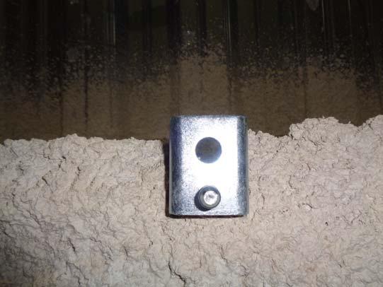
10 ~ FIRE PROOFED BEAM NOTICE ~ Notch Fire Proofing At Edge And Top Of With Saw Blade To Expose Steel For Placement Of Legs. Top Of Flange Notches Only Need To Be (1-1/4") Inch Long To Allow For Upper Legs Of. Press Or Hammer Tap Tight To Edge And Top Of Steel. Tighten Bolt Allowing It To Burrow Through Bottom Of Flange Fire Proofing And Become Tight Against Steel. Continue Tightening Until Head Of Bolt Breaks Away. Inspect To Comfirm Is Tight And Secure To Steel. Prior To Installation Lower Bolt To Clear Fire Proofing On Bottom Side Of Flange. Attachment Usable For Both Upper And Lower Beam Flange Installations. This Attachment May Or May Not Require Patching Of The Fire Proofing. Consult With Project Structural Engineer Of Record And Authority Having Jurisdiction Prior To Notching Fire Proofing. Use Depicted () Beam Clamp For Flange Thickness (0.1875") Inch, To A Thickness Of (1.260") Inch. Use (L-C) For Flange Thickness (1.300") Inch, To A Thickness Of (3.00") Inch. For Thickness (2.1250") To (3.00") Inch Use (L) Or (L-C). Upper Legs Shall Be In Full Contact With Beam Flange Steel, Upper Legs Shall Be In Full Contact With Beam Flange Steel, (1-1/4") (3/4") (1-1/4") (3/4") (1-1/4") (3") L Bolt Shall Be In Full Contact With Beam Flange Steel, Bolt Head, FPBN-SH Fire Proofed Beam Notice - Single Hanger

11 LINK TO VIDEO
12 ~ BEAM BENDING NOTICE ~ As Determined By The Project Structural Engineer Of Record, Excessive Loading Of A Can Cause Bending Of The Beam. To Provide Resistance To Beam Bending Due To Threaded Rod Vertical Hanger Clamp Loading, See Industries Stiffener Detail (BFS-TRVH). (1 Of 2 Or More) Vertical Hanger Clamps Used To Support Strut Trapeze. Each Of Which May Or May Not Require A Beam Flange Stiffener Per Detail (BFS-TRVH) As Determined By The Project Structural Engineer Of Record, Excessive Loading Of A Beam Flange Can Cause Bending Of The Beam. To Provide Resistance To Beam Bending Due To Cantileved Strut Loading, See Stiffener Detail (BFS-CST). As Determined By The Project Structural Engineer Of Record, Excessive Loading Of A Can Cause Bending Of The Beam. To Provide Resistance To Beam Bending Due To Seismic Brace Lateral And/Or Splayed Loading, See Stiffener Details (LBK-SSC1), (LBK-SSC2) And (LBK-SSC2-2). To Provide Resistance To Beam Bending Due To Seismic Brace Parallel Loading, See Industries Stiffener Details (BFS-SSC1), (BFS-SSC2) And (BFS-SSC3). As Determined By The Project Structural Engineer Of Record, Excessive Loading Of A Beam Flange Can Cause Bending Of The Beam. To Provide Resistance To Beam Bending Due To Cantileved Strut Loading, See Stiffener Detail (BFS-CST). SSC Application specific seismic and non seismic beam loading and bending may differ from that depicted. If, when, where, and how many Stiffener(s) and/or Lateral Brace Kicker(s) are required shall be as determined by the project Structural Engineer Of Record. BBN Beam Bending Notice
13 SINGLE HANGER STRUT HANGER () () (0.1875") Flange Thickness For Threaded Rod Sizes, (3/8"), (1/2") & (5/8") (0.1875") Flange Thickness For Single Strut Depth Sizes, (13/16"), (1"), (1-3/8") & (0.1875") Max. (0.375") Flange Thickness For Single Strut Depth Size, (2-7/16") (1-1/2") Depth Per Detail Depth Per Detail (1-1/2") (0.1875") Max. (1.125") Flange Thickness For Back-To-Back Strut Depth Size, (0.1875") Max. (0.9375") Flange Thickness For Back-To-Back Strut Depth Size, (0.1875") Max. (0.5625") Flange Thickness For Back-To-Back Strut Depth Size, (2-3/4") Listed Flange Thickness Applicable For Both Upper And Lower Flanges. Actual With Strut And/Or Threaded Rod Assembly Combinations Shall Be As Engineered. Steel Beam And/Or Joist Are. -FRD - Fitment Reference Detail
14 SEISMIC BRACE Perpendicular To Beam Length SEISMIC BRACE Parallel To Beam Length SEISMIC BRACE Skewed To Beam Length (-C) With Cup Point Spacer (-C) With Cup Point Spacer (-C) With Cup Point Spacer (0.1875") Flange Thickness For Threaded Rod Sizes, (3/8"), (1/2") & (5/8") Cup Point Space Depicted Perpendicular To Beam Length (SSC) With RIGID Or CABLE Bracing Per SEBO (0.1875") Flange Thickness For Threaded Rod Sizes, (3/8"), (1/2") & (5/8") Depicted Parallel To Beam Length (SSC) With RIGID Or CABLE Bracing Per SEBO Cup Point Space (0.1875") Flange Thickness For Threaded Rod Sizes, (3/8"), (1/2") & (5/8") SSC SSC Depicted Skewed To Beam Length (SSC) With RIGID Or CABLE Bracing Per SEBO Cup Point Space Cup Point Space Cup Point Space Cup Point Space SSC SSC Listed Flange Thickness Applicable For Both Upper And Lower Flanges. Actual Seismic Brace Assembly Combinations Shall Be As Engineered By Others. Steel Beam And/Or Joist Are. -C-FRD -C - Fitment Reference Detail
15 SINGLE HANGER STRUT HANGER (L) (L) (2.00") Max. (3.00") Flange Thickness For Threaded Rod Sizes, (3/8"), (1/2"), (5/8") & (3/4") (1.875") Max. (3.00") Flange Thickness For Single Strut Depth Sizes, (13/16"), (1"), (1-3/8") & (1.875") Max. (2.250") Flange Thickness For Single Strut Depth Size, (2-7/16") (1-1/2") Depth Per Detail Depth Per Detail (1-1/2") (1.00") Max. (3.00") Flange Thickness For Back-To-Back Strut Depth Size, (0.8125") Max. (2.625") Flange Thickness For Back-To-Back Strut Depth Size, (0.4375") Max. (1.875") Flange Thickness For Back-To-Back Strut Depth Size, (2-3/4") Listed Flange Thickness Applicable For Both Upper And Lower Flanges. Actual With Strut And/Or Threaded Rod Assembly Combinations Shall Be As Engineered. Steel Beam And/Or Joist Are. (0.1875") Max. (1.375") Flange Thickness For Back-To-Back Strut Depth Size, (3-1/4") L L L L-FRD L - Fitment Reference Detail
16 SINGLE HANGER STRUT HANGER (L-C) With Cup Point Spacer (L-C) With Cup Point Spacer (1.250") Max. (3.00") Flange Thickness For Threaded Rod Sizes, (3/8"), (1/2"), (5/8") & (3/4") Cup Point Space, Hidden Behind Threaded Rod (1.125") Max. (3.00") Flange Thickness For Single Strut Depth Sizes, (13/16"), (1"), (1-3/8") & (1.125") Max. (2.250") Flange Thickness For Single Strut Depth Size, (2-7/16") (1-1/2") Depth Per Detail Cup Point Space Depth Per Detail (1-1/2") (0.250") Max. (2.1875") Flange Thickness For Back-To-Back Strut Depth Size, (0.1875") Max. (2.000") Flange Thickness For Back-To-Back Strut Depth Size, (0.1875") Max. (1.625") Flange Thickness For Back-To-Back Strut Depth Size, (2-3/4") Listed Flange Thickness Applicable For Both Upper And Lower Flanges. Actual With Strut And/Or Threaded Rod Assembly Combinations Shall Be As Engineered. Steel Beam And/Or Joist Are. (0.1875") Max. (1.375") Flange Thickness For Back-To-Back Strut Depth Size, (3-1/4") L Cup Point Space L L L-C-FRD L-C - Fitment Reference Detail
17 Detail (BFS-TRVH), Or L-C Vertical Support Rod Size 3/8" 1/2" 5/8" SEISMIC FpT (LRFD) FpC (LRFD) 2,040 lbs. 2,040 lbs. 2,040 lbs. 1,500 lbs. 1,500 lbs. 1,500 lbs. FpC Controlled By Capacity Of (1") Inch EMT Conduit Stiffener Member And Beam Depth Of (36") Inch. Conduit Stiffener Not Required For Gravity Only Loads. Bolt Shall Be In Full Contact With Beam Flange Steel, MSS Allowable Tension 730 lbs. 1,350 lbs. 2,160 lbs. Listed Capacities Based On FM Global Seismic Testing And Engineered Analysis. Testing Was Performed (Without) Restraining Strap. Was Not Tested For Use On Beams With "S" Section Shapes. Weaker Components / Conditions Within Overall Design And Application Including, But Not Limited To The Building Structure Install Throat Steel-To-Steel Tight To Flange Of Beam. Tighten Each Bolt Until Tight Against And Head Of Bolt Breaks Away. : Use (L-C) For Flange Thickness (1.300") Inch, To A Thickness Of (3.00") Inch. (1 And 2 Of 2) () s. See Upper And Lower Strut Nuts (1 And 2 Of 2) () s. See (1 And 2 Of 2) EMT Conduit Rod Stiffener Clamps FpT Tension Only Design Applications Threaded Rod Stiffener Not Required Beam Depth (36") Inch (1 Of 2) EMT Conduit Rod Stiffener Clamps (6") Max. (1") EMT Conduit Fit Between Strut Nuts, (2 Of 2) EMT Conduit Rod Stiffener Clamps Upper And Lower Strut Nuts Sized To Fit Threaded Rod And Tightened Hand Tight Plus (1/4) Turn, Or Stronger Threaded Rod Size, (0.1875") Thickness. See For Design Applications Rod Stiffener Requirements For Threaded Rod Below Lower Shall Be Engineered By Other, (6") Max. For Design Applications (1") EMT Conduit Rod Stiffener Member Required Between s, FpT (Tension) BFS-TRVH FpC (Compression) FpT (Tension) Stiffener - Threaded Rod Vertical Hanger Connection FpC (Compression) FpT (Tension)
18 Detail (BFS-CST), Or L-C Vertical Support Rod Size 5/8" MSS Allowable Tension 2,160 lbs. SEISMIC FpT (LRFD) FpC (LRFD) 2,040 lbs. 1,500 lbs. FpC Controlled By Capacity Of (1") Inch EMT Conduit Stiffener Member And Beam Depth Of (36") Inch. Conduit Stiffener Not Required For Gravity Only Loads. Listed Capacities Based On FM Global Seismic Testing And Engineered Analysis. Testing Was Performed (Without) Restraining Strap. Was Not Tested For Use On Beams With "S" Section Shapes. Weaker Components / Conditions Within Overall Design And Application Including, But Not Limited To The Building Structure Install Throat Steel-To-Steel Tight To Flange Of Beam. Tighten Each Bolt Until Tight Against And Head Of Bolt Breaks Away. The Number Of Stiffener Assemblies Required And The Spacing Between A Given Stiffener Assembly And The Load Point To Shall Be Determined By The Project Structural Engineer Of Record. : Use (L-C) For Flange Thickness (1.300") Inch, To A Thickness Of (3.00") Inch. Bolt Shall Be In Full Contact With Beam Flange Steel, (1 And 2 Of 2) () s. See FpC (Compression) FpT (Tension) (1 And 2 Of 2) () s. See (1 Of 2) EMT Conduit Rod Stiffener Clamps (1") EMT Conduit Fit Between Strut Nuts, (6") Max. (6") Max. (1") EMT Conduit Rod Stiffener Member Can Be Orientated In Plan About The Center Of The Threaded Rod Other Than Depicted, Beam Depth (36") Inch (5/8") Inch Or Stronger Threaded Rod. Secured To Each With Double Strut Nuts Or Hex Nuts Each Beam Clamp End Connection. Tightened Hand Tight Plus (1/4) Turn, (6") Max. (1") EMT Conduit Rod Stiffener Member Can Be Orientated In Plan About The Center Of The Threaded Rod Other Than (6") Max. Depicted, FpC (Compression) FpT (Tension) See NOTICE Depicted Cantilevered Strut May Vary (0.1875") Thickness. See For Design Applications Rod Stiffener Requirements For Threaded Rod Connected To Cantilevered Strut Shall Be Engineered By Other, Depicted Cantilevered Strut May Vary BFS-CST Stiffener - Cantilevered Strut Trapeze Connection
19 Listed Capacities Based On FM Global Seismic Testing And Engineered Analysis. Testing Was Performed (Without) Restraining Strap. Was Not Tested For Use On Beams With "S" Section Shapes. Weaker Components / Conditions Within Overall Design And Application Including, But Not Limited To The Building Structure Install Throat Steel-To-Steel Tight To Flange Of Beam. For (-C) Tighten Beam Clamp Bolt Until Cup Point End Of Spacer Is Tight Against Beam Flange And Head Of Bolt Breaks Away. For () Tighten Bolt Until Tight Against And Head Of Bolt Breaks Away. For (-C) -C Or C Which Indicates Cup Point Spacer Required To Be Installed At Threaded End Of Bolt, May Or May Not Be Stamped Into. Bolt Shall Be In Full Contact With Beam Flange Steel, Detail (BFS-SSC1) -C SSC 440 lbs., Or L-C N / A For Stiffener Assembly Brace Angle From Vertical Parallel To Parallel To Parallel To Beam Length Beam Length Beam Length 30º to 44º Fp (LRFD) 45º to 60º Fp (LRFD) 61º to 75º Fp (LRFD) 550 lbs. 478 lbs. SEISMIC FpT = 2,040 lbs. (LRFD) SEISMIC FpC = 1,500 lbs. (LRFD) (1 Of 1) Upper Flange Conn. () FpC (Compression) FpT (Tension) (1 Of 1) () s (1") EMT Conduit Fit Between Strut Nuts, (1 And 2 Of 2) EMT Conduit Rod Stiffener Clamps Beam Depth (36") Inch (1 And 2 Of 2) Industries EMT Conduit Rod Stiffener Clamps (6") Max. (1") EMT Conduit Fit Between Strut Nuts, Depicted Parallel To Beam Length (SSC) With RIGID Or CABLE Bracing. See Detail (SSC51) Or Detail (SSC51-J) Horizontal Fp BFS-SSC1 SSC (1 Of 1) (-C) (0.1875") Thickness. See (5/8") Inch Or Stronger Threaded Rod. Secured To Upper Beam Clamp With Double Strut Nuts Tightened Hand Tight Plus (1/4) Turn, And Secured To Lower With (SSC) Seismic Bracket, Using Strut Nut And Hex Nut With Lock Washer As Depicted, Tightened Hand Tight Plus (1/4) Turn, Cup Point Spacer, For (-C) Seismic Brace Conn., Depicted Parallel To Beam Length (SSC) With RIGID Or CABLE Bracing. See Detail (SSC51) Or Detail (SSC51-J) Stiffener - SSC Parallel Brace Connection (6") Max. (1 Of 1) Lower Flange Conn. (-C)
20 Detail (BFS-SSC1-OS) -C SSC 440 lbs., Or L-C N / A For Stiffener Assembly Bolt Shall Be In Full Contact With Beam Flange Steel, Brace Angle From Vertical Parallel To Parallel To Parallel To Beam Length Beam Length Beam Length 30º to 44º Fp (LRFD) 45º to 60º Fp (LRFD) 61º to 75º Fp (LRFD) 550 lbs. 478 lbs. SEISMIC FpT = 2,040 lbs. (LRFD) SEISMIC FpC = 1,500 lbs. (LRFD) Listed Capacities Based On FM Global Seismic Testing And Engineered Analysis. Testing Was Performed (Without) Restraining Strap. Was Not Tested For Use On Beams With "S" Section Shapes. Weaker Components / Conditions Within Overall Design And Application Including, But Not Limited To The Building Structure Install Throat Steel-To-Steel Tight To Flange Of Beam. Tighten Each Bolt Until Tight Against And Head Of Bolt Breaks Away. Spacing Between A Given Stiffener Assembly And The Seismic Brace Load Point To Shall Be Determined By The Project Structural Engineer Of Record. (1 And 2 Of 2) () s FpC (Compression) FpT (Tension) (1 And 2 Of 2) () s (1 Of 2) EMT Conduit Rod Stiffener Clamps (1") EMT Conduit Fit Between Strut Nuts, (6") Max. (6") Max. (1") EMT Conduit Rod Stiffener Member Can Be Orientated In Plan About The Center Of The Threaded Rod Other Than Depicted, See NOTICE Beam Depth (36") Inch (5/8") Inch Or Stronger Threaded Rod. Secured To Each With Double Strut Nuts Or Hex Nuts Each Beam Clamp End Connection. Tightened Hand Tight Plus (1/4) Turn, (6") Max. (1") EMT Conduit Rod Stiffener Member Can Be Orientated In Plan About The Center Of The Threaded Rod Other Than (6") Max. Depicted, Depicted Parallel FpC (Compression) To Beam Length FpT (Tension) (SSC) With RIGID Or CABLE Bracing. See Detail (SSC51) Or Detail (SSC51-J) Horizontal Fp BFS-SSC1-OS SSC (1 Of 1) (-C) With Cup Point Spacer Cup Point Spacer, For (-C) Seismic Brace Conn., (0.1875") Thickness. See (1 Of 1) (-C) With Cup Point Spacer Depicted Parallel To Beam Length (SSC) With RIGID Or CABLE Bracing. See Detail (SSC51) Or Detail (SSC51-J) Stiffener - SSC Parallel Brace Connection
21 Detail (LBK-SSC1) -C SSC 493 lbs. Brace Angle From Vertical Perpendicular Perpendicular Perpendicular To Beam Length To Beam Length To Beam Length 30º to 44º Fp (LRFD) 45º to 60º Fp (LRFD) 61º to 75º Fp (LRFD) 493 lbs. 435 lbs. Listed Capacities Based On FM Global Seismic Testing And Engineered Analysis. Testing Was Performed (Without) Restraining Strap. Was Not Tested For Use On Beams With "S" Section Shapes. Weaker Components / Conditions Within Overall Design And Application Including, But Not Limited To The Building Structure Capacity Shall Control. Lateral Brace Kicker Assembly Shall Be Installed So That It Is Orientated Perpendicular To The Length Of The Steel Beam It Is Attached To. Install Throat Steel-To-Steel Tight To Flange Of Beam. Tighten Bolt Until Cup Point End Of Spacer Is Tight Against And Head Of Bolt Breaks Away. -C Or C Which Indicates Cup Point Spacer Required To Be Installed At Threaded End Of Bolt, May Or May Not Be Stamped Into. Various Seismic Brace To Building Structure Connections SSC Vertical Horizontal Fp Lateral Brace Kicker Angle Per Chart, LBK-SSC1 Lateral Kicker (SSC) With RIGID Bracing, Lateral Brace Kicker Same Side As Brace To Be Installed Perpendicular To Beam Length (1 And 2 Of 2) (-C) With Cup Point Spacer SSC SSC Seismic Brace (SSC) With RIGID Or CABLE Bracing. See Detail (SSC51) Or Secure Detail (SSC51-J) Industries Seismic Hardware To Beam Clamp Using (5/8") ASTM A307 Or Stronger Bolt With Lock Washer And Hex Nut Tightened Until Lock Washer Is Flat, Plus (1/4) Turn, Bolt Prior To Installation Of Seismic Hardware, Industries Cup Point Spacer, (0.1875") Thickness Industries Cup Point Spacer, Bolt With Cup Point Spacer Shall Be In Full Contact With Steel, (1 And 2 Of 2) (-C) With Cup Point Spacer Lateral Brace Kicker Angle, Seismic Lateral Brace Kicker - SSC Perpendicular Brace Connection Various Seismic Brace To Building Structure Connections SSC SSC Vertical Horizontal Fp SSC OPTIONAL: Lateral Brace Kicker Opposite Side Of Brace To Be Installed Perpendicular To Beam Length Do Not Connect Seismic Hardware To Bolt
22 Detail (SVC51) Vertical Support Rod Size ANSI / MSS SP-58 Allowable Tension SEISMIC (LRFD) 3/8" 730 lbs. 1/2" 1,350 lbs. 3,531 lbs. 5/8" 1,350 lbs. 3/4" 1,350 lbs. Compliant Per 2016 NFPA-13, Paragraph For Single Hanger Piping 8" And Smaller Listed Capacities Based On Testing And Engineered Analysis. Testing Was Performed (Without) Restraining Strap. Was Not Tested For Use On Beams With "S" Section Shapes. Weaker Components / Conditions Within Overall Design And Application Including, But Not Limited To The Building Structure Install Throat Steel-To-Steel Tight To Flange Of Beam. Tighten Bolt Until Tight Against And Head Of Bolt Breaks Away. : Use (L-C) For Flange Thickness (1.300") Inch, To A Thickness Of (3.00") Inch. (1 Of 1) (). See (0.1875") Thickness. See Bolt Shall Be In Full Contact With Underside Of Steel, Bolt Prior To Installation Of Rod, Rod, ASTM A563 Coupler Nut, One End Sized To Fit (1/2-13) Bolt, And One End Sized To Fit Vertical Support Rod. Coupler Nut Thread Engagement Onto Bolt Threads Shall Be Minimum (1/2") Inch. Coupler Nut Shall Not Contact Underside Of SVC51 Seismic Vertical Connection - Single Attachment
23 Detail (SVC51-EF) Vertical Support Rod Size 3/8" 1/2" 5/8" ANSI / MSS SP-58 Allowable Tension 730 lbs. 1,350 lbs. 2,160 lbs. SEISMIC (LRFD) 2,040 lbs. Compliant Per 2016 NFPA-13, Paragraph For Single Hanger Piping 10" And Smaller Listed Capacities Based On Testing And Engineered Analysis. Testing Was Performed (Without) Restraining Strap. Was Not Tested For Use On Beams With "S" Section Shapes. Weaker Components / Conditions Within Overall Design And Application Including, But Not Limited To The Building Structure Install Throat Steel-To-Steel Tight To Flange Of Beam. Tighten Bolt Until Tight Against And Head Of Bolt Breaks Away. : Use (L-C) For Flange Thickness (1.300") Inch, To A Thickness Of (3.00") Inch. Bolt Shall Be In Full Contact With Underside Of Steel, Bolt Head, Rod Placement Off-Set At Edge Of Allows For Full Beam Depth Vertical Adjustment, Upper And Lower Strut Nuts Sized To Fit Vertical Support Rod. Installed Hand Tight Plus (1/4) Turn. Lower Strut Nut Is Not Required For Gravity Vertical Supports Not Required To Resist Uplift Forces, (1 Of 1) (). See Rod. Supported Within Using Strut Nut Size To Fit Rod Bolt, (0.1875") Thickness. See Thick Flange Notice (1 Of 1) (). See Rod. Supported Within Using Strut Nuts Size To Fit Rod SVC51-EF Seismic Vertical Connection - Single Attachment
24 Detail (SVC51L-EF) L Or L-C See Flange Thickness Notes Vertical Support Rod Size ANSI / MSS SP-58 Allowable Tension 3/8" 730 lbs. 1/2" 1,350 lbs. 5/8" 2,160 lbs. 3/4" 2,160 lbs. SEISMIC (LRFD) 2,040 lbs. Compliant Per 2016 NFPA-13, Paragraph For Single Hanger Piping 10" And Smaller For Thickness (1.300") To (3.00") Use (L-C). Listed Capacities Based On Testing And Engineered Analysis. Testing Was Performed (Without) Restraining Strap. Was Not Tested For Use On Beams With "S" Section Shapes. Weaker Components / Conditions Within Overall Design And Application Including, But Not Limited To The Building Structure Install Throat Steel-To-Steel Tight To Flange Of Beam. Tighten Bolt Until Tight Against And Head Of Bolt Breaks Away. For Thickness (1.300") To (3.00") Use (L-C). For Thickness (2.1250") To (3.00") Use (L) Or (L-C) Bolt With Cup Point Spacer Shall Be In Full Contact With Underside Of Beam Flange Steel For Thickness (2.1250") To (3.00") Use (L) Or (L-C) Bolt Shall Be In Full Contact With Underside Of Steel Bolt Head, (L-C) With Cup Point Spacer Rod Placement Off-Set At Edge Of Allows For Full Beam Depth Vertical Adjustment, Upper And Lower Strut Nuts Sized To Fit Vertical Support Rod. Installed Hand Tight Plus (1/4) Turn. Lower Strut Nut Is Not Required For Gravity Vertical Supports Not Required To Resist Uplift Forces, (1 Of 1) (L-C) Or (L). See Thick Flange Rod. Supported Within Using Hex Or Strut Nut Size To Fit Rod L Bolt, L (1 Of 1) (L-C) Or (L). See Thick Flange Rod. Supported Within Using Hex Or Strut Nut Size To Fit Rod SVC51L-EF Seismic Vertical Connection - Single Attachment
25 Detail (SVC51-C2) 4" 5" 6" 7" 8" 9" 12" 15" 18" 21" 24" ANSI / MSS SP-58 Allowable Tension 316 lbs. 271 lbs. 237 lbs. 211 lbs. 190 lbs. 172 lbs. 135 lbs. 111 lbs. 95 lbs. 82 lbs. 73 lbs. Cantilever End Load SEISMIC FpT (LRFD) FpC (LRFD) 583 lbs. 499 lbs. 437 lbs. 388 lbs. 350 lbs. 317 lbs. 199 lbs. 134 lbs. 96 lbs. 72 lbs. 56 lbs. 503 lbs. 386 lbs. 313 lbs. 263 lbs. 227 lbs. 176 lbs. 94 lbs. 59 lbs. 40 lbs. 29 lbs. 22 lbs. Listed Capacities Based On Testing And Engineered Analysis. Testing Was Performed (Without) Restraining Strap. Was Not Tested For Use On Beams With "S" Section Shapes. Weaker Components / Conditions Within Overall Design And Application Including, But Not Limited To The Building Structure Install Throat Steel-To-Steel Tight To Flange Of Beam. Tighten Each Bolt Until Strut Is Tight Against And Head Of Bolt Breaks Away. Use Of An Alternate Strut Shall Be Engineered. Multiple Loads Can Be Placed Across Span, Provided The Accumulated Loads Do Not Exceed Applicable Listing Within Chart. : Use (L-C) For Flange Thickness (1.300") Inch, To A Thickness Of (3.00") Inch. Rod Or FpC (Compression) FpT (Tension) (1 Of 1) (). See (0.70") Minimum (1 Of 1) (). See (0.1875") Thickness. See Threaded Rod Conn., To Strut Hex Nut, Anvil Square Strut Washer And Anvil Strut Nut Tighten Hand Tight Plus (1/4) Turn Anvil (AS 200), (AS 200H) Or (AS 200EH) (12 ga. 1-5/8"x1-5/8") Single Strut Member, Bolt Shall Be In Full Contact With Inside Back Of Strut Metal. Bolt Shall Not Overhang Or Pass Through Holes, Slots Or Openings In The Back Of The Strut Member. Outside Back Of Strut Shall Be In Full Contact With Underside Of Steel, SVC51-C2 Bolt Head, Attachment Can Be Other Minimum Entire Length Must Be In Contact With Underside Of (0.70") Seismic Vertical Connection - Single Attachment FpC (Compression) FpT (Tension) Rod Or
26 Detail (SVC51L-C2) L L L L L L L L L L L 4" 5" 6" 7" 8" 9" 12" 15" 18" 21" 24" ANSI/MSS SP-58 Allowable Tension 350 lbs. 300 lbs. 262 lbs. 233 lbs. 210 lbs. 190 lbs. 150 lbs. 123 lbs. 105 lbs. 91 lbs. 80 lbs. Cantilever End Load SEISMIC FpT (LRFD) FpC (LRFD) 982 lbs. 841 lbs. 736 lbs. 654 lbs. 588 lbs. 535 lbs. 420 lbs. 346 lbs. 294 lbs. 256 lbs. 226 lbs. 624 lbs. 479 lbs. 388 lbs. 326 lbs. 282 lbs. 247 lbs. 141 lbs. 88 lbs. 60 lbs. 43 lbs. 33 lbs. Listed Capacities Based On Testing And Engineered Analysis. Testing Was Performed (Without) Restraining Strap. Was Not Tested For Use On Beams With "S" Section Shapes. Weaker Components / Conditions Within Overall Design And Application Including, But Not Limited To The Building Structure Install Throat Steel-To-Steel Tight To Flange Of Beam. Tighten Each Bolt Until Strut Is Tight Against And Head Of Bolt Breaks Away. Use Of An Alternate Strut Shall Be Engineered. Multiple Loads Can Be Placed Across Span, Provided The Accumulated Loads Do Not Exceed Applicable Listing Within Chart. Rod Or FpC (Compression) FpT (Tension) L (0.70") (1 Of 1) (L) (1 Of 1) (L) (0.1875") Thickness Threaded Rod Conn., To Strut Anvil (AS 200 BTB) (12 ga. 3-1/4"x1-5/8") Double Back-To-Back Manufacturer Spot Welded Single (12 ga. 1-5/8"x1-5/8") Strut Members, Both Having Solid Backs (Without) Holes Or Slotted Openings, Hex Nut, Anvil Square Strut Washer And Anvil Strut Nut Tighten Hand Tight Plus (1/4) Turn Bolt Shall Be In Full Contact With Inside Back Of Strut Metal. Both Strut Rails Shall Be In Full Contact With Underside Of Lower Steel, SBC51L-C2 Bolt Entire Length Must Be In Contact With Underside Of Minimum L (0.70") Seismic Vertical Connection - Single Attachment (3-1/4") Rod Or
27 Detail (SVC51-C3) 4" 5" 6" 7" 8" 9" 12" 15" 18" 21" 24" ANSI / MSS SP-58 Allowable Tension 407 lbs. 356 lbs. 316 lbs. 285 lbs. 259 lbs. 237 lbs. 190 lbs. 155 lbs. 128 lbs. 109 lbs. 94 lbs. Cantilever End Load SEISMIC FpT (LRFD) FpC (LRFD) 749 lbs. 655 lbs. 583 lbs. 525 lbs. 476 lbs. 437 lbs. 350 lbs. 262 lbs. 190 lbs. 143 lbs. 111 lbs. 503 lbs. 386 lbs. 313 lbs. 263 lbs. 227 lbs. 176 lbs. 94 lbs. 59 lbs. 40 lbs. 29 lbs. 22 lbs. Listed Capacities Based On Testing And Engineered Analysis. Testing Was Performed (Without) Restraining Strap. Was Not Tested For Use On Beams With "S" Section Shapes. Weaker Components / Conditions Within Overall Design And Application Including, But Not Limited To The Building Structure Install Throat Steel-To-Steel Tight To Flange Of Beam. Tighten Each Bolt Until Strut Is Tight Against And Head Of Bolt Breaks Away. Use Of An Alternate Strut Shall Be Engineered. Multiple Loads Can Be Placed Across Span, Provided The Accumulated Loads Do Not Exceed Applicable Listing Within Chart. : Use (L-C) For Flange Thickness (1.300") Inch, To A Thickness Of (3.00") Inch. Rod Or FpC (Compression) FpT (Tension) (1 Of 1) (). See (0.70") (3") Minimum (1 Of 1) (). See (0.1875") Thickness. See Threaded Rod Conn., To Strut Hex Nut, Anvil Square Strut Washer And Anvil Strut Nut Tighten Hand Tight Plus (1/4) Turn Anvil (AS 200), (AS 200H) Or (AS 200EH) (12 ga. 1-5/8"x1-5/8") Single Strut Member, Bolt Shall Be In Full Contact With Inside Back Of Strut Metal. Bolt Shall Not Overhang Or Pass Through Holes, Slots Or Openings In The Back Of The Strut Member. Outside Back Of Strut Shall Be In Full Contact With Underside Of Steel, SVC51-C3 Bolt Head, Attachment Can Be Other (3") Minimum Entire Length Must Be In Contact With Underside Of (0.70") Seismic Vertical Connection - Single Attachment FpC (Compression) FpT (Tension) Rod Or
28 Detail (SVC51L-C3) ANSI/MSS SP-58 Allowable Tension Cantilever End Load L 4" 450 lbs. 1,262 lbs. L 5" 393 lbs. 1,104 lbs. L L 6" 7" 350 lbs. 315 lbs. 982 lbs. 883 lbs. L 8" 286 lbs. 802 lbs. L L 9" 12" 262 lbs. 210 lbs. 736 lbs. 588 lbs. L L 15" 18" 175 lbs. 150 lbs. 490 lbs. 420 lbs. L L 21" 24" 131 lbs. 116 lbs. 368 lbs. 326 lbs. SEISMIC FpT (LRFD) FpC (LRFD) 624 lbs. 479 lbs. 388 lbs. 326 lbs. 282 lbs. 247 lbs. 141 lbs. 88 lbs. 60 lbs. 43 lbs. 33 lbs. Listed Capacities Based On Testing And Engineered Analysis. Testing Was Performed (Without) Restraining Strap. Was Not Tested For Use On Beams With "S" Section Shapes. Weaker Components / Conditions Within Overall Design And Application Including, But Not Limited To The Building Structure Install Throat Steel-To-Steel Tight To Flange Of Beam. Tighten Each Bolt Until Strut Is Tight Against And Head Of Bolt Breaks Away. Use Of An Alternate Strut Shall Be Engineered. Multiple Loads Can Be Placed Across Span, Provided The Accumulated Loads Do Not Exceed Applicable Listing Within Chart. Rod Or FpC (Compression) FpT (Tension) L (0.70") (3") (1 Of 1) (L) (1 Of 1) (L) (0.1875") Thickness Threaded Rod Conn., To Strut Anvil (AS 200 BTB) (12 ga. 3-1/4"x1-5/8") Double Back-To-Back Manufacturer Spot Welded Single (12 ga. 1-5/8"x1-5/8") Strut Members, Both Having Solid Backs (Without) Holes Or Slotted Openings, Hex Nut, Anvil Square Strut Washer And Anvil Strut Nut Tighten Hand Tight Plus (1/4) Turn Bolt Shall Be In Full Contact With Inside Back Of Strut Metal. Both Strut Rails Shall Be In Full Contact With Underside Of Lower Steel, SBC51L-C3 Bolt Entire Length Must Be In Contact With Underside Of (3") Minimum L (0.70") Seismic Vertical Connection - Single Attachment (3-1/4") Rod Or
29 Detail (SVC51-C4) 4" 5" 6" 7" 8" 9" 12" 15" 18" 21" 24" ANSI / MSS SP-58 Allowable Tension 475 lbs. 422 lbs. 380 lbs. 336 lbs. 294 lbs. 261 lbs. 195 lbs. 155 lbs. 128 lbs. 109 lbs. 94 lbs. Cantilever End Load SEISMIC FpT (LRFD) FpC (LRFD) 875 lbs. 777 lbs. 700 lbs. 603 lbs. 527 lbs. 468 lbs. 350 lbs. 279 lbs. 232 lbs. 198 lbs. 172 lbs. 503 lbs. 386 lbs. 313 lbs. 263 lbs. 227 lbs. 176 lbs. 94 lbs. 59 lbs. 40 lbs. 29 lbs. 22 lbs. Listed Capacities Based On Testing And Engineered Analysis. Testing Was Performed (Without) Restraining Strap. Was Not Tested For Use On Beams With "S" Section Shapes. Weaker Components / Conditions Within Overall Design And Application Including, But Not Limited To The Building Structure Install Throat Steel-To-Steel Tight To Flange Of Beam. Tighten Each Bolt Until Strut Is Tight Against And Head Of Bolt Breaks Away. Use Of An Alternate Strut Shall Be Engineered. Multiple Loads Can Be Placed Across Span, Provided The Accumulated Loads Do Not Exceed Applicable Listing Within Chart. : Use (L-C) For Flange Thickness (1.300") Inch, To A Thickness Of (3.00") Inch. Rod Or FpC (Compression) FpT (Tension) (1 Of 1) (). See (0.70") (4") Minimum (1 Of 1) (). See (0.1875") Thickness. See Threaded Rod Conn., To Strut Hex Nut, Anvil Square Strut Washer And Anvil Strut Nut Tighten Hand Tight Plus (1/4) Turn Anvil (AS 200), (AS 200H) Or (AS 200EH) (12 ga. 1-5/8"x1-5/8") Single Strut Member, Bolt Shall Be In Full Contact With Inside Back Of Strut Metal. Bolt Shall Not Overhang Or Pass Through Holes, Slots Or Openings In The Back Of The Strut Member. Outside Back Of Strut Shall Be In Full Contact With Underside Of Steel, SVC51-C4 Bolt Head, Attachment Can Be Other (4") Minimum Entire Length Must Be In Contact With Underside Of (0.70") Seismic Vertical Connection - Single Attachment FpC (Compression) FpT (Tension) Rod Or
30 Detail (SVC51L-C4) L L L L L L L L L L L 4" 5" 6" 7" 8" 9" 12" 15" 18" 21" 24" ANSI/MSS SP-58 Allowable Tension 525 lbs. 466 lbs. 420 lbs. 381 lbs. 350 lbs. 323 lbs. 262 lbs. 221 lbs. 190 lbs. 168 lbs. 150 lbs. Cantilever End Load SEISMIC FpT (LRFD) FpC (LRFD) 1,472 lbs. 1,309 lbs. 1,178 lbs. 1,071 lbs. 982 lbs. 906 lbs. 736 lbs. 620 lbs. 535 lbs. 471 lbs. 420 lbs. 624 lbs. 479 lbs. 388 lbs. 326 lbs. 282 lbs. 247 lbs. 141 lbs. 88 lbs. 60 lbs. 43 lbs. 33 lbs. Listed Capacities Based On Testing And Engineered Analysis. Testing Was Performed (Without) Restraining Strap. Was Not Tested For Use On Beams With "S" Section Shapes. Weaker Components / Conditions Within Overall Design And Application Including, But Not Limited To The Building Structure Install Throat Steel-To-Steel Tight To Flange Of Beam. Tighten Each Bolt Until Strut Is Tight Against And Head Of Bolt Breaks Away. Use Of An Alternate Strut Shall Be Engineered. Multiple Loads Can Be Placed Across Span, Provided The Accumulated Loads Do Not Exceed Applicable Listing Within Chart. Rod Or FpC (Compression) FpT (Tension) L (0.70") (4") (1 Of 1) (L) (1 Of 1) (L) (0.1875") Thickness Threaded Rod Conn., To Strut Anvil (AS 200 BTB) (12 ga. 3-1/4"x1-5/8") Double Back-To-Back Manufacturer Spot Welded Single (12 ga. 1-5/8"x1-5/8") Strut Members, Both Having Solid Backs (Without) Holes Or Slotted Openings, Hex Nut, Anvil Square Strut Washer And Anvil Strut Nut Tighten Hand Tight Plus (1/4) Turn Bolt Shall Be In Full Contact With Inside Back Of Strut Metal. Both Strut Rails Shall Be In Full Contact With Underside Of Lower Steel, SBC51L-C4 Bolt Entire Length Must Be In Contact With Underside Of (4") Minimum L (0.70") Seismic Vertical Connection - Single Attachment (3-1/4") Rod Or
31 Detail (SVC51-C5) 4" 5" 6" 7" 8" 9" 12" 15" 18" 21" 24" ANSI / MSS SP-58 Allowable Tension 527 lbs. 471 lbs. 392 lbs. 336 lbs. 294 lbs. 261 lbs. 195 lbs. 155 lbs. 128 lbs. 109 lbs. 94 lbs. Cantilever End Load SEISMIC FpT (LRFD) FpC (LRFD) 971 lbs. 844 lbs. 703 lbs. 603 lbs. 527 lbs. 468 lbs. 350 lbs. 279 lbs. 232 lbs. 198 lbs. 172 lbs. 503 lbs. 386 lbs. 313 lbs. 263 lbs. 227 lbs. 176 lbs. 94 lbs. 59 lbs. 40 lbs. 29 lbs. 22 lbs. Listed Capacities Based On Testing And Engineered Analysis. Testing Was Performed (Without) Restraining Strap. Was Not Tested For Use On Beams With "S" Section Shapes. Weaker Components / Conditions Within Overall Design And Application Including, But Not Limited To The Building Structure Install Throat Steel-To-Steel Tight To Flange Of Beam. Tighten Each Bolt Until Strut Is Tight Against And Head Of Bolt Breaks Away. Use Of An Alternate Strut Shall Be Engineered. Multiple Loads Can Be Placed Across Span, Provided The Accumulated Loads Do Not Exceed Applicable Listing Within Chart. : Use (L-C) For Flange Thickness (1.300") Inch, To A Thickness Of (3.00") Inch. Rod Or FpC (Compression) FpT (Tension) (1 Of 1) (). See (0.70") (5") Minimum (1 Of 1) (). See (0.1875") Thickness. See Threaded Rod Conn., To Strut Hex Nut, Anvil Square Strut Washer And Anvil Strut Nut Tighten Hand Tight Plus (1/4) Turn Anvil (AS 200), (AS 200H) Or (AS 200EH) (12 ga. 1-5/8"x1-5/8") Single Strut Member, Bolt Shall Be In Full Contact With Inside Back Of Strut Metal. Bolt Shall Not Overhang Or Pass Through Holes, Slots Or Openings In The Back Of The Strut Member. Outside Back Of Strut Shall Be In Full Contact With Underside Of Steel, SVC51-C5 Bolt Head, Attachment Can Be Other (5") Minimum Entire Length Must Be In Contact With Underside Of (0.70") Seismic Vertical Connection - Single Attachment FpC (Compression) FpT (Tension) Rod Or
32 Detail (SVC51L-C5) L L L L L L L L L L L 4" 5" 6" 7" 8" 9" 12" 15" 18" 21" 24" ANSI/MSS SP-58 Allowable Tension 583 lbs. 525 lbs. 477 lbs. 437 lbs. 403 lbs. 375 lbs. 308 lbs. 262 lbs. 228 lbs. 201 lbs. 181 lbs. Cantilever End Load SEISMIC FpT (LRFD) FpC (LRFD) 1,636 lbs. 1,472 lbs. 1,339 lbs. 1,227 lbs. 1,132 lbs. 1,052 lbs. 865 lbs. 736 lbs. 640 lbs. 566 lbs. 507 lbs. 624 lbs. 479 lbs. 388 lbs. 326 lbs. 282 lbs. 247 lbs. 141 lbs. 88 lbs. 60 lbs. 43 lbs. 33 lbs. Listed Capacities Based On Testing And Engineered Analysis. Testing Was Performed (Without) Restraining Strap. Was Not Tested For Use On Beams With "S" Section Shapes. Weaker Components / Conditions Within Overall Design And Application Including, But Not Limited To The Building Structure Install Throat Steel-To-Steel Tight To Flange Of Beam. Tighten Each Bolt Until Strut Is Tight Against And Head Of Bolt Breaks Away. Use Of An Alternate Strut Shall Be Engineered. Multiple Loads Can Be Placed Across Span, Provided The Accumulated Loads Do Not Exceed Applicable Listing Within Chart. Rod Or FpC (Compression) FpT (Tension) L (0.70") (5") (1 Of 1) (L) (1 Of 1) (L) (0.1875") Thickness Threaded Rod Conn., To Strut Anvil (AS 200 BTB) (12 ga. 3-1/4"x1-5/8") Double Back-To-Back Manufacturer Spot Welded Single (12 ga. 1-5/8"x1-5/8") Strut Members, Both Having Solid Backs (Without) Holes Or Slotted Openings, Hex Nut, Anvil Square Strut Washer And Anvil Strut Nut Tighten Hand Tight Plus (1/4) Turn Bolt Shall Be In Full Contact With Inside Back Of Strut Metal. Both Strut Rails Shall Be In Full Contact With Underside Of Lower Steel, SBC51L-C5 Bolt Entire Length Must Be In Contact With Underside Of (5") Minimum L (0.70") Seismic Vertical Connection - Single Attachment (3-1/4") Rod Or
33 Detail (SVC51-C6) 4" 5" 6" 7" 8" 9" 12" 15" 18" 21" 24" ANSI / MSS SP-58 Allowable Tension 570 lbs. 471 lbs. 392 lbs. 336 lbs. 294 lbs. 261 lbs. 195 lbs. 155 lbs. 128 lbs. 109 lbs. 94 lbs. Cantilever End Load SEISMIC FpT (LRFD) FpC (LRFD) 1,050 lbs. 844 lbs. 703 lbs. 603 lbs. 527 lbs. 468 lbs. 350 lbs. 279 lbs. 232 lbs. 198 lbs. 172 lbs. 503 lbs. 386 lbs. 313 lbs. 263 lbs. 227 lbs. 176 lbs. 94 lbs. 59 lbs. 40 lbs. 29 lbs. 22 lbs. Listed Capacities Based On Testing And Engineered Analysis. Testing Was Performed (Without) Restraining Strap. Was Not Tested For Use On Beams With "S" Section Shapes. Weaker Components / Conditions Within Overall Design And Application Including, But Not Limited To The Building Structure Install Throat Steel-To-Steel Tight To Flange Of Beam. Tighten Each Bolt Until Strut Is Tight Against And Head Of Bolt Breaks Away. Use Of An Alternate Strut Shall Be Engineered. Multiple Loads Can Be Placed Across Span, Provided The Accumulated Loads Do Not Exceed Applicable Listing Within Chart. : Use (L-C) For Flange Thickness (1.300") Inch, To A Thickness Of (3.00") Inch. Rod Or FpC (Compression) FpT (Tension) (1 Of 1) (). See (0.70") (6") Minimum (1 Of 1) (). See (0.1875") Thickness. See Threaded Rod Conn., To Strut Hex Nut, Anvil Square Strut Washer And Anvil Strut Nut Tighten Hand Tight Plus (1/4) Turn Anvil (AS 200), (AS 200H) Or (AS 200EH) (12 ga. 1-5/8"x1-5/8") Single Strut Member, Bolt Shall Be In Full Contact With Inside Back Of Strut Metal. Bolt Shall Not Overhang Or Pass Through Holes, Slots Or Openings In The Back Of The Strut Member. Outside Back Of Strut Shall Be In Full Contact With Underside Of Steel, SVC51-C6 Bolt Head, Attachment Can Be Other (6") Minimum Entire Length Must Be In Contact With Underside Of (0.70") Seismic Vertical Connection - Single Attachment FpC (Compression) FpT (Tension) Rod Or
34 Detail (SVC51L-C6) L L L L L L L L L L L 4" 5" 6" 7" 8" 9" 12" 15" 18" 21" 24" ANSI/MSS SP-58 Allowable Tension 630 lbs. 572 lbs. 525 lbs. 484 lbs. 450 lbs. 420 lbs. 350 lbs. 300 lbs. 262 lbs. 233 lbs. 210 lbs. Cantilever End Load SEISMIC FpT (LRFD) FpC (LRFD) 1,767 lbs. 1,606 lbs. 1,472 lbs. 1,359 lbs. 1,262 lbs. 1,178 lbs. 982 lbs. 841 lbs. 736 lbs. 634 lbs. 553 lbs. 624 lbs. 479 lbs. 388 lbs. 326 lbs. 282 lbs. 247 lbs. 141 lbs. 88 lbs. 60 lbs. 43 lbs. 33 lbs. Listed Capacities Based On Testing And Engineered Analysis. Testing Was Performed (Without) Restraining Strap. Was Not Tested For Use On Beams With "S" Section Shapes. Weaker Components / Conditions Within Overall Design And Application Including, But Not Limited To The Building Structure Install Throat Steel-To-Steel Tight To Flange Of Beam. Tighten Each Bolt Until Strut Is Tight Against And Head Of Bolt Breaks Away. Use Of An Alternate Strut Shall Be Engineered. Multiple Loads Can Be Placed Across Span, Provided The Accumulated Loads Do Not Exceed Applicable Listing Within Chart. Rod Or FpC (Compression) FpT (Tension) L (0.70") (6") (1 Of 1) (L) (1 Of 1) (L) (0.1875") Thickness Threaded Rod Conn., To Strut Anvil (AS 200 BTB) (12 ga. 3-1/4"x1-5/8") Double Back-To-Back Manufacturer Spot Welded Single (12 ga. 1-5/8"x1-5/8") Strut Members, Both Having Solid Backs (Without) Holes Or Slotted Openings, Hex Nut, Anvil Square Strut Washer And Anvil Strut Nut Tighten Hand Tight Plus (1/4) Turn Bolt Shall Be In Full Contact With Inside Back Of Strut Metal. Both Strut Rails Shall Be In Full Contact With Underside Of Lower Steel, SBC51L-C6 Bolt Entire Length Must Be In Contact With Underside Of (6") Minimum L (0.70") Seismic Vertical Connection - Single Attachment (3-1/4") Rod Or
35 Detail (SVC51-Ca) 4" 5" 6" 7" 8" 9" 12" 15" 18" 21" 24" ANSI / MSS SP-58 Allowable Tension 201 lbs. 154 lbs. 125 lbs. 105 lbs. 91 lbs. 80 lbs. 58 lbs. 46 lbs. 38 lbs. 32 lbs. 28 lbs. Cantilever End Load SEISMIC (LRFD) 503 lbs. 386 lbs. 313 lbs. 263 lbs. 227 lbs. 176 lbs. 94 lbs. 59 lbs. 40 lbs. 29 lbs. 22 lbs. Listed Capacities Based On Testing And Engineered Analysis. Testing Was Performed (Without) Restraining Strap. Beam Clamp Was Not Tested For Use On Beams With "S" Section Shapes. Weaker Components / Conditions Within Overall Design And Application Including, But Not Limited To The Building Structure Install Throat Steel-To-Steel Tight To Flange Of Beam. Tighten Bolt Until Strut Is Tight Against Underside Of And Head Of Bolt Breaks Away. Use Of An Alternate Strut Shall Be Engineered. Multiple Loads Can Be Placed Across Span, Provided The Accumulated Loads Do Not Exceed Applicable Listing Within Chart. : Use (L-C) For Flange Thickness (1.300") Inch, To A Thickness Of (3.00") Inch. Bolt Head, Bolt Shall Be In Full Contact With Inside Back Of Strut Metal. Bolt Shall Not Overhang Or Pass Through Holes, Slots Or Openings In The Back Of The Strut Member. Outside Back Of Strut Shall Be In Full Contact With Underside Of Beam Flange Steel, SVC51-Ca (1 Of 1) (). See (0.1875") Thickness. See (1 Of 1) (). See (0.70") Anvil (AS 200), (AS 200H) Or (AS 200EH) (12 ga. 1-5/8"x1-5/8") Single Strut Member, Seismic Vertical Connection - Single Attachment
36 Detail (SVC51L-Ca) L L L L L L L L L L L 4" 5" 6" 7" 8" 9" 12" 15" 18" 21" 24" ANSI/MSS SP-58 Allowable Tension 222 lbs. 170 lbs. 138 lbs. 116 lbs. 100 lbs. 88 lbs. 65 lbs. 51 lbs. 42 lbs. 36 lbs. 31 lbs. Cantilever End Load SEISMIC (LRFD) 624 lbs. 479 lbs. 388 lbs. 326 lbs. 282 lbs. 247 lbs. 141 lbs. 88 lbs. 60 lbs. 43 lbs. 33 lbs. Listed Capacities Based On Testing And Engineered Analysis. Testing Was Performed (Without) Restraining Strap. Was Not Tested For Use On Beams With "S" Section Shapes. Weaker Components / Conditions Within Overall Design And Application Including, But Not Limited To The Building Structure Install Throat Steel-To-Steel Tight To Flange Of Beam. Tighten Bolt Until Strut Is Tight Against Underside Of And Torque- Off Head Of Bolt Breaks Away. Use Of An Alternate Strut Shall Be Engineered. Multiple Loads Can Be Placed Across Span, Provided The Accumulated Loads Do Not Exceed Applicable Listing Within Chart. Hex Nut, Anvil Square Strut Washer And Anvil Strut Nut Tighten Hand Tight Plus (1/4) Turn Threaded Rod Conn., To Strut Bolt Head, Bolt Shall Be In Full Contact With Inside Back Of Strut Metal. Bolt Shall Not Overhang Or Pass Through Holes, Slots Or Openings In The Back Of The Strut Members. Both Strut Rails Shall Be In Full Contact With Underside Of Lower Steel, SVC51L-Ca (1 Of 1) (L) (0.1875") Thickness L (1 Of 1) (L). See (0.70") Anvil (AS 200 BTB) (12 ga. 3-1/4"x1-5/8") Double Back-To-Back Manufacturer Spot Welded Single (12 ga. 1-5/8"x1-5/8") Strut Members, Both Having Solid Backs (Without) Holes Or Slotted Openings, Rod Or Seismic Vertical Connection - Single Attachment FpC (Compression) FpT (Tension) (3-1/4")
37 Detail (SVC51-Cb) 2" 3" 4" 5" 6" 7" 8" 9" 10" 11" 12" ANSI / MSS SP-58 Allowable Tension 246 lbs. 179 lbs. 141 lbs. 116 lbs. 99 lbs. 86 lbs. 76 lbs. 68 lbs. 62 lbs. 56 lbs. 52 lbs. Cantilever End Load SEISMIC (LRFD) 615 lbs. 448 lbs. 353 lbs. 291 lbs. 247 lbs. 205 lbs. 161 lbs. 129 lbs. 106 lbs. 88 lbs. 75 lbs. Listed Capacities Based On Testing And Engineered Analysis. Testing Was Performed (Without) Restraining Strap. Beam Clamp Was Not Tested For Use On Beams With "S" Section Shapes. Weaker Components / Conditions Within Overall Design And Application Including, But Not Limited To The Building Structure Install Throat Steel-To-Steel Tight To Flange Of Beam. Tighten Bolt Until Strut Is Tight Against Underside Of And Head Of Bolt Breaks Away. Use Of An Alternate Strut Shall Be Engineered. Multiple Loads Can Be Placed Across Span, Provided The Accumulated Loads Do Not Exceed Applicable Listing Within Chart. : Use (L-C) For Flange Thickness (1.300") Inch, To A Thickness Of (3.00") Inch. (1 Of 1) (). See (1 Of 1) (). See (0.1875") Thickness. See Anvil (AS 200), (AS 200H) Or (AS 200EH) (12 ga. 1-5/8"x1-5/8") Single Strut Member, Threaded Rod Conn., To Strut Hex Nut, Anvil Square Strut Washer And Anvil Strut Nut Tighten Hand Tight Plus (1/4) Turn Bolt Shall Be In Full Contact With Inside Back Of Strut Metal. Bolt Shall Not Overhang Or Pass Through Holes, Slots Or Openings In The Back Of The Strut Member. Outside Back Of Strut Shall Be In Full Contact With Underside Of Steel, SVC51-Cb Bolt Head, Rod Or (0.70") End Of Strut Shall Extend Beyond Attachment Can Be Other Seismic Vertical Connection - Single Attachment
38 Detail (SVC51L-Cb) L L L L L L L L L L L 2" 3" 4" 5" 6" 7" 8" 9" 10" 11" 12" ANSI/MSS SP-58 Allowable Tension 272 lbs. 198 lbs. 156 lbs. 128 lbs. 109 lbs. 95 lbs. 84 lbs. 75 lbs. 68 lbs. 62 lbs. 57 lbs. Cantilever End Load (1 Of 1) (L) SEISMIC (LRFD) 763 lbs. 557 lbs. 438 lbs. 361 lbs. 307 lbs. 267 lbs. 236 lbs. 212 lbs. 192 lbs. 175 lbs. 161 lbs. Listed Capacities Based On Testing And Engineered Analysis. Testing Was Performed (Without) Restraining Strap. Beam Clamp Was Not Tested For Use On Beams With "S" Section Shapes. Weaker Components / Conditions Within Overall Design And Application Including, But Not Limited To The Building Structure Install Throat Steel-To-Steel Tight To Flange Of Beam. Tighten Bolt Until Strut Is Tight Against Underside Of And Head Of Bolt Breaks Away. Use Of An Alternate Strut Shall Be Engineered. Multiple Loads Can Be Placed Across Span, Provided The Accumulated Loads Do Not Exceed Applicable Listing Within Chart. (1 Of 1) (L) (0.1875") Thickness Attachment Can Be Other Anvil (AS 200 BTB) (12 ga. 3-1/4"x1-5/8") Double Back-To-Back Manufacturer Spot Welded Single (12 ga. 1-5/8"x1-5/8") Strut Members, Both Having Solid Backs (Without) Holes Or Slotted Openings, Threaded Rod Conn., To Strut Hex Nut, Anvil Square Strut Washer And Anvil Strut Nut Tighten Hand Tight Plus (1/4) Turn Bolt Shall Be In Full Contact With Inside Back Of Strut Metal. Bolt Shall Not Overhang Or Pass Through Holes, Slots Or Openings In The Back Of The Strut Members. Both Strut Rails Shall Be In Full Contact With Underside Of Lower Steel, Bolt Head, Rod Or (0.70") L End Of Strut Shall Extend Beyond (3-1/4") SVC51L-Cb Seismic Vertical Connection - Single Attachment
39 Detail (SVC52) Width 6" 12" ANSI / MSS SP-58 Allowable Tension 1,900 lbs. 1,780 lbs. SEISMIC (LRFD) 1,934 lbs. 18" 1,135 lbs. Compliant Per 2016 NFPA-13, Paragraph For Single Hanger Piping 6" And Smaller Listed Capacities Based On Testing And Engineered Analysis. Testing Was Performed (Without) Restraining Strap. Beam Clamp Was Not Tested For Use On Beams With "S" Section Shapes. Weaker Components / Conditions Within Overall Design And Application Including, But Not Limited To The Building Structure Install Each Throat Steel-To-Steel Tight To Flange Of Beam. Tighten Each Bolt Until Strut Is Tight Against And Head Of Bolt Breaks Away. Use Of An Alternate Strut Shall Be Engineered. : Use (L-C) For Flange Thickness (1.300") Inch, To A Thickness Of (3.00") Inch. (18") Bolt Shall Be In Full Contact With Inside Back Of Strut Metal. Bolt Shall Not Overhang Or Pass Through Holes, Slots Or Openings In The Back Of The Strut Member. Outside Back Of Strut Shall Be In Full Contact With Underside Of Steel, Bolt Head, (1 Of 2) (). See End Of Strut Shall Be Flush With Or Extend Beyond, Rod Or (2 Of 2) (). See (0.1875") Thickness. See Anywhere Between Clamps Bolt, Attachment Can Be Other Anvil (AS 200), (AS 200H) Or (AS 200EH) (12 ga. 1-5/8"x1-5/8") Single Strut Member, Threaded Rod Conn., To Strut Hex Nut, Anvil Square Strut Washer And Anvil Strut Nut Tighten Hand Tight Plus (1/4) Turn SVC52 Seismic Vertical Connection - Double Attachment
40 Detail (SVC52L) Width ANSI/MSS SP-58 Allowable Tension SEISMIC (LRFD) L 18" 2,100 lbs. 2,152 lbs. Compliant Per 2016 NFPA-13, Paragraph For Single Hanger Piping 10" And Smaller Listed Capacities Based On Testing And Engineered Analysis. Testing Was Performed (Without) Restraining Strap. Beam Clamp Was Not Tested For Use On Beams With "S" Section Shapes. Weaker Components / Conditions Within Overall Design And Application Including, But Not Limited To The Building Structure Install Each Throat Steel-To-Steel Tight To Flange Of Beam. Tighten Each Bolt Until Strut Is Tight Against And Head Of Bolt Breaks Away. Use Of An Alternate Strut Shall Be Engineered. (18") (1 Of 2) (L) (2 Of 2) (L) (0.1875") Thickness Anvil (AS 200 BTB) (12 ga. 3-1/4"x1-5/8") Double Back-To-Back Manufacturer Spot Welded Single (12 ga. 1-5/8"x1-5/8") Strut Members, Both Having Solid Backs (Without) Holes Or Slotted Openings Attachment Can Be Other Bolt Shall Be In Full Contact With Inside Back Of Strut Metal. Bolt Shall Not Overhang Or Pass Through Holes, Slots Or Openings In The Back Of The Strut Members. Both Strut Rails Shall Be In Full Contact With Underside Of Lower Steel, Bolt Head, L End Of Strut Shall Be Flush With Or Extend Beyond, Rod Or Anywhere Between Clamps L Bolt, (3-1/4") Threaded Rod Conn., To Strut Hex Nut, Anvil Square Strut Washer And Anvil Strut Nut Tighten Hand Tight Plus (1/4) Turn SVC52L Seismic Vertical Connection - Double Attachment
41 Detail (SVC52a) Width 6" 12" 18" ANSI / MSS SP-58 Allowable Tension 1,900 lbs. 1,780 lbs. 1,135 lbs. SEISMIC (LRFD) 1,934 lbs. Compliant Per 2016 NFPA-13, Paragraph For Single Hanger Piping 6" And Smaller Listed Capacities Based On Testing And Engineered Analysis. Testing Was Performed (Without) Restraining Strap. Beam Clamp Was Not Tested For Use On Beams With "S" Section Shapes. Weaker Components / Conditions Within Overall Design And Application Including, But Not Limited To The Building Structure Install Each Throat Steel-To-Steel Tight To Flange Of Beam. Tighten Bolt Until Tight Against Beam Flange And Head Of Bolt Breaks Away. Use Of An Alternate Strut Shall Be Engineered. : Use (L-C) For Flange Thickness (1.300") Inch, To A Thickness Of (3.00") Inch. (18") Bolt Hidden Behind Depicted Threaded Rod, Shall Be In Full Contact With Underside Of Beam Flange Steel, (1 Of 2) (). See (1/2") Bolt Or Hex Nut, Square Strut Washer On Strut End And Strut Nut On End. Tighten Until Strut Is Hand Tight To Underside Of Beam Flange, Plus (1/4) Turn Bolt Head, Rod Or (2 Of 2) (). See (0.1875") Thickness. See Anywhere Between Clamps (1/2") Bolt Or Hex Nut, Square Strut Washer On Strut End And Strut Nut On End. Tighten Until Strut Is Hand Tight To Underside Of Beam Flange, Plus (1/4) Turn Attachment Can Be Other Anvil (AS 200), (AS 200H) Or (AS 200EH) (12 ga. 1-5/8"x1-5/8") Single Strut Member, Threaded Rod Conn., To Strut Hex Nut, Anvil Square Strut Washer And Anvil Strut Nut Tighten Hand Tight Plus (1/4) Turn SVC52a Seismic Vertical Connection - Double Attachment
42 Detail (SVC52a-DS) Width ANSI/MSS SP-58 Allowable Tension SEISMIC (LRFD) 18" 1,900 lbs. 1,934 lbs. Compliant Per 2016 NFPA-13, Paragraph For Single Hanger Piping 10" And Smaller Listed Capacities Based On Testing And Engineered Analysis. Testing Was Performed (Without) Restraining Strap. Beam Clamp Was Not Tested For Use On Beams With "S" Section Shapes. Weaker Components / Conditions Within Overall Design And Application Including, But Not Limited To The Building Structure Install Each Throat Steel-To-Steel Tight To Flange Of Beam. Tighten Bolt Until Tight Against Beam Flange And Head Of Bolt Breaks Away. Use Of An Alternate Strut Shall Be Engineered. : Use (L-C) For Flange Thickness (1.300") Inch, To A Thickness Of (3.00") Inch. (18") Bolt Hidden Behind Depicted Threaded Rod, Shall Be In Full Contact With Underside Of Beam Flange Steel, (1 Of 2) (). See Bolt Head, (2 Of 2) (). See (0.1875") Thickness. See Attachment Can Be Other Anvil (AS 300 BTB), (AS 300H BTB), (AS 300EH BTB), (AS 200 BTB), (AS 200H BTB) Or (AS 200EH BTB) (12 ga. X-X/X"x1-5/8") Double Back-To-Back Manufacturer Spot Welded Strut Members, Installed Tight To Underside Of Steel, (2-3/4") Minimum (1/2") Bolt Or Hex Nut, Square Strut Washer On Strut End And Strut Nut On End. Tighten Until Strut Is Hand Tight To Underside Of Beam Flange, Plus (1/4) Turn Rod Or Anywhere Between Clamps (1/2") Bolt Or Hex Nut, Square Strut Washer On Strut End And Strut Nut On End. Tighten Until Strut Is Hand Tight To Underside Of Beam Flange, Plus (1/4) Turn Threaded Rod Conn., To Strut Hex Nut, Anvil Square Strut Washer And Anvil Strut Nut Tighten Hand Tight Plus (1/4) Turn SVC52a-DS Seismic Vertical Connection - Double Attachment
43 Detail (SVC52-C4) 6" 9" 12" 15" 18" 21" 24" 27" 30" ANSI/MSS SP-58 Allowable Tension 337 lbs. 254 lbs. 195 lbs. 155 lbs. 128 lbs. 109 lbs. 94 lbs. 83 lbs. 74 lbs. Cantilever End Load SEISMIC (LRFD) 703 lbs. 468 lbs. 350 lbs. 279 lbs. 221 lbs. 166 lbs. 130 lbs. 103 lbs. 84 lbs. Listed Capacities Based On Testing And Engineered Analysis. Testing Was Performed (Without) Restraining Strap. Was Not Tested For Use On Beams With "S" Section Shapes. Weaker Components / Conditions Within Overall Design And Application Including, But Not Limited To The Building Structure Install Each Throat Steel-To-Steel Tight To Flange Of Beam. Tighten Each Bolt Until Strut Is Tight Against And Torque- Off Head Of Bolt Breaks Away. Use Of An Alternate Strut Shall Be Engineered. Multiple Loads Can Be Placed Across Span, Provided The Accumulated Loads Do Not Exceed Applicable Listing Within Chart. : Use (L-C) For Flange Thickness (1.300") Inch, To A Thickness Of (3.00") Inch. (4") Minimum Bolt Shall Be In Full Contact With Inside Back Of Strut Metal. Bolt Shall Not Overhang Or Pass Through Holes, Slots Or Openings In The Back Of The Strut Member. Outside Back Of Strut Shall Be In Full Contact With Underside Of Steel, Bolt Head, (1 Of 2) (). See End Of Strut Without Vertical Support Rod Shall Be Flush With Or Extend Beyond Beam Clamp (2 Of 2) (). See (0.1875") Thickness. See Attachment Can Be Other Threaded Rod Conn., To Strut (0.70") Anvil (AS 200), (AS 200H) Or (AS 200EH) (12 ga. 1-5/8"x1-5/8") Single Strut Member, Hex Nut, Anvil Square Strut Washer And Anvil Strut Nut Tighten Hand Tight Plus (1/4) Turn Rod Or SVC52-C4 Seismic Vertical Connection - Double Attachment
44 Detail (SVC52L-C4) L L L L L L L L L 6" 9" 12" 15" 18" 21" 24" 27" 30" ANSI/MSS SP-58 Allowable Tension 372 lbs. 281 lbs. 226 lbs. 189 lbs. 162 lbs. 142 lbs. 126 lbs. 114 lbs. 104 lbs. Cantilever End Load SEISMIC (LRFD) 1,169 lbs. 884 lbs. 710 lbs. 594 lbs. 510 lbs. 447 lbs. 398 lbs. 358 lbs. 326 lbs. Listed Capacities Based On Testing And Engineered Analysis. Testing Was Performed (Without) Restraining Strap. Was Not Tested For Use On Beams With "S" Section Shapes. Weaker Components / Conditions Within Overall Design And Application Including, But Not Limited To The Building Structure Install Each Throat Steel-To-Steel Tight To Flange Of Beam. Tighten Each Bolt Until Strut Is Tight Against And Torque- Off Head Of Bolt Breaks Away. Use Of An Alternate Strut Shall Be Engineered. Multiple Loads Can Be Placed Across Span, Provided The Accumulated Loads Do Not Exceed Applicable Listing Within Chart. (4") Minimum (1 Of 2) (L) (2 Of 2) (L) (0.1875") Thickness Threaded Rod Conn., To Strut Hex Nut, Anvil Square Strut Washer And Anvil Strut Nut Tighten Hand Tight Plus (1/4) Turn Anvil (AS 200 BTB) (12 ga. 3-1/4"x1-5/8") Double Back-To-Back Manufacturer Spot Welded Single (12 ga. 1-5/8"x1-5/8") Strut Members, Both Having Solid Backs (Without) Holes Or Slotted Openings, Bolt Shall Be In Full Contact With Inside Back Of Strut Metal. Bolt Shall Not Overhang Or Pass Through Holes, Slots Or Openings In The Back Of The Strut Members. Both Strut Rails Shall Be In Full Contact With Underside Of Lower Steel, SVC52L-C4 Bolt Head, L End Of Strut Without Rod Shall Be Flush With Or Extend Beyond L (0.70") Seismic Vertical Connection - Double Attachment (3-1/4") Rod Or
45 Detail (SVC52-C6) 6" 9" 12" 15" 18" 21" 24" 27" 30" ANSI/MSS SP-58 Allowable Tension 392 lbs. 261 lbs. 195 lbs. 155 lbs. 128 lbs. 109 lbs. 94 lbs. 83 lbs. 74 lbs. Cantilever End Load SEISMIC (LRFD) 703 lbs. 468 lbs. 350 lbs. 279 lbs. 232 lbs. 198 lbs. 172 lbs. 152 lbs. 136 lbs. Listed Capacities Based On Testing And Engineered Analysis. Testing Was Performed (Without) Restraining Strap. Was Not Tested For Use On Beams With "S" Section Shapes. Weaker Components / Conditions Within Overall Design And Application Including, But Not Limited To The Building Structure Install Each Throat Steel-To-Steel Tight To Flange Of Beam. Tighten Each Bolt Until Strut Is Tight Against And Torque- Off Head Of Bolt Breaks Away. Use Of An Alternate Strut Shall Be Engineered. Multiple Loads Can Be Placed Across Span, Provided The Accumulated Loads Do Not Exceed Applicable Listing Within Chart. : Use (L-C) For Flange Thickness (1.300") Inch, To A Thickness Of (3.00") Inch. (6") Minimum Bolt Shall Be In Full Contact With Inside Back Of Strut Metal. Bolt Shall Not Overhang Or Pass Through Holes, Slots Or Openings In The Back Of The Strut Member. Outside Back Of Strut Shall Be In Full Contact With Underside Of Steel, Bolt Head, (1 Of 2) (). See End Of Strut Without Vertical Support Rod Shall Be Flush With Or Extend Beyond Beam Clamp (2 Of 2) (). See (0.1875") Thickness. See Attachment Can Be Other Threaded Rod Conn., To Strut (0.70") Anvil (AS 200), (AS 200H) Or (AS 200EH) (12 ga. 1-5/8"x1-5/8") Single Strut Member, Hex Nut, Anvil Square Strut Washer And Anvil Strut Nut Tighten Hand Tight Plus (1/4) Turn Rod Or SVC52-C6 Seismic Vertical Connection - Double Attachment
46 Detail (SVC52L-C6) L L L L L L L L L 6" 9" 12" 15" 18" 21" 24" 27" 30" ANSI/MSS SP-58 Allowable Tension 492 lbs. 389 lbs. 321 lbs. 274 lbs. 238 lbs. 211 lbs. 189 lbs. 172 lbs. 157 lbs. Cantilever End Load SEISMIC (LRFD) 1,545 lbs. 1,221 lbs. 1,009 lbs. 860 lbs. 742 lbs. 634 lbs. 553 lbs. 490 lbs. 439 lbs. Liisted Capacities Based On Testing And Engineered Analysis. Testing Was Performed (Without) Restraining Strap. Was Not Tested For Use On Beams With "S" Section Shapes. Weaker Components / Conditions Within Overall Design And Application Including, But Not Limited To The Building Structure Install Each Throat Steel-To-Steel Tight To Flange Of Beam. Tighten Each Bolt Until Strut Is Tight Against And Torque- Off Head Of Bolt Breaks Away. Use Of An Alternate Strut Shall Be Engineered. Multiple Loads Can Be Placed Across Span, Provided The Accumulated Loads Do Not Exceed Applicable Listing Within Chart. (6") Minimum (1 Of 2) (L) (2 Of 2) (L) (0.1875") Thickness Threaded Rod Conn., To Strut Hex Nut, Anvil Square Strut Washer And Anvil Strut Nut Tighten Hand Tight Plus (1/4) Turn Anvil (AS 200 BTB) (12 ga. 3-1/4"x1-5/8") Double Back-To-Back Manufacturer Spot Welded Single (12 ga. 1-5/8"x1-5/8") Strut Members, Both Having Solid Backs (Without) Holes Or Slotted Openings, Bolt Shall Be In Full Contact With Inside Back Of Strut Metal. Bolt Shall Not Overhang Or Pass Through Holes, Slots Or Openings In The Back Of The Strut Members. Both Strut Rails Shall Be In Full Contact With Underside Of Lower Steel, SVC52L-C6 Bolt Head, L End Of Strut Without Rod Shall Be Flush With Or Extend Beyond L (0.70") Seismic Vertical Connection - Double Attachment (3-1/4") Rod Or
47 Detail (SVC52L-C8) L L L L L L L L L 6" 9" 12" 15" 18" 21" 24" 27" 30" ANSI/MSS SP-58 Allowable Tension 576 lbs. 470 lbs. 397 lbs. 343 lbs. 302 lbs. 270 lbs. 244 lbs. 223 lbs. 205 lbs. Cantilever End Load SEISMIC (LRFD) 1,808 lbs. 1,475 lbs. 1,118 lbs. 892 lbs. 742 lbs. 634 lbs. 553 lbs. 490 lbs. 439 lbs. Listed Capacities Based On Testing And Engineered Analysis. Testing Was Performed (Without) Restraining Strap. Was Not Tested For Use On Beams With "S" Section Shapes. Weaker Components / Conditions Within Overall Design And Application Including, But Not Limited To The Building Structure Install Each Throat Steel-To-Steel Tight To Flange Of Beam. Tighten Each Bolt Until Strut Is Tight Against And Torque- Off Head Of Bolt Breaks Away. Use Of An Alternate Strut Shall Be Engineered. Multiple Loads Can Be Placed Across Span, Provided The Accumulated Loads Do Not Exceed Applicable Listing Within Chart. (8") Minimum (1 Of 2) (L) (2 Of 2) (L) (0.1875") Thickness Threaded Rod Conn., To Strut Hex Nut, Anvil Square Strut Washer And Anvil Strut Nut Tighten Hand Tight Plus (1/4) Turn Anvil (AS 200 BTB) (12 ga. 3-1/4"x1-5/8") Double Back-To-Back Manufacturer Spot Welded Single (12 ga. 1-5/8"x1-5/8") Strut Members, Both Having Solid Backs (Without) Holes Or Slotted Openings, Bolt Shall Be In Full Contact With Inside Back Of Strut Metal. Bolt Shall Not Overhang Or Pass Through Holes, Slots Or Openings In The Back Of The Strut Members. Both Strut Rails Shall Be In Full Contact With Underside Of Lower Steel, SVC52L-C8 Bolt Head, L End Of Strut Without Rod Shall Be Flush With Or Extend Beyond L (0.70") Seismic Vertical Connection - Double Attachment (3-1/4") Rod Or
48 Detail (SVC52L-C10) L L L L L L L L L 6" 9" 12" 15" 18" 21" 24" 27" 30" ANSI/MSS SP-58 Allowable Tension 638 lbs. 533 lbs. 458 lbs. 401 lbs. 357 lbs. 322 lbs. 293 lbs. 269 lbs. 240 lbs. Cantilever End Load SEISMIC (LRFD) 2,003 lbs. 1,493 lbs. 1,118 lbs. 892 lbs. 742 lbs. 634 lbs. 553 lbs. 490 lbs. 439 lbs. Listed Capacities Based On Testing And Engineered Analysis. Testing Was Performed (Without) Restraining Strap. Was Not Tested For Use On Beams With "S" Section Shapes. Weaker Components / Conditions Within Overall Design And Application Including, But Not Limited To The Building Structure Install Each Throat Steel-To-Steel Tight To Flange Of Beam. Tighten Each Bolt Until Strut Is Tight Against And Torque- Off Head Of Bolt Breaks Away. Use Of An Alternate Strut Shall Be Engineered. Multiple Loads Can Be Placed Across Span, Provided The Accumulated Loads Do Not Exceed Applicable Listing Within Chart. (10") Minimum (1 Of 2) (L) (2 Of 2) (L) (0.1875") Thickness Threaded Rod Conn., To Strut Hex Nut, Anvil Square Strut Washer And Anvil Strut Nut Tighten Hand Tight Plus (1/4) Turn Anvil (AS 200 BTB) (12 ga. 3-1/4"x1-5/8") Double Back-To-Back Manufacturer Spot Welded Single (12 ga. 1-5/8"x1-5/8") Strut Members, Both Having Solid Backs (Without) Holes Or Slotted Openings, Bolt Shall Be In Full Contact With Inside Back Of Strut Metal. Bolt Shall Not Overhang Or Pass Through Holes, Slots Or Openings In The Back Of The Strut Members. Both Strut Rails Shall Be In Full Contact With Underside Of Lower Steel, SVC52L-C10 Bolt Head, L End Of Strut Without Rod Shall Be Flush With Or Extend Beyond L (0.70") Seismic Vertical Connection - Double Attachment (3-1/4") Rod Or
49 Detail (SVC52L-C12) L L L L L L L L L 6" 9" 12" 15" 18" 21" 24" 27" 30" ANSI/MSS SP-58 Allowable Tension 685 lbs. 584 lbs. 509 lbs. 451 lbs. 404 lbs. 351 lbs. 305 lbs. 269 lbs. 240 lbs. Cantilever End Load SEISMIC (LRFD) 2,152 lbs. 1,493 lbs. 1,118 lbs. 892 lbs. 742 lbs. 634 lbs. 553 lbs. 490 lbs. 439 lbs. Listed Capacities Based On Testing And Engineered Analysis. Testing Was Performed (Without) Restraining Strap. Was Not Tested For Use On Beams With "S" Section Shapes. Weaker Components / Conditions Within Overall Design And Application Including, But Not Limited To The Building Structure Install Each Throat Steel-To-Steel Tight To Flange Of Beam. Tighten Each Bolt Until Strut Is Tight Against And Torque- Off Head Of Bolt Breaks Away. Use Of An Alternate Strut Shall Be Engineered. Multiple Loads Can Be Placed Across Span, Provided The Accumulated Loads Do Not Exceed Applicable Listing Within Chart. (12") Minimum (1 Of 2) (L) (2 Of 2) (L) (0.1875") Thickness Threaded Rod Conn., To Strut Hex Nut, Anvil Square Strut Washer And Anvil Strut Nut Tighten Hand Tight Plus (1/4) Turn Anvil (AS 200 BTB) (12 ga. 3-1/4"x1-5/8") Double Back-To-Back Manufacturer Spot Welded Single (12 ga. 1-5/8"x1-5/8") Strut Members, Both Having Solid Backs (Without) Holes Or Slotted Openings, Bolt Shall Be In Full Contact With Inside Back Of Strut Metal. Bolt Shall Not Overhang Or Pass Through Holes, Slots Or Openings In The Back Of The Strut Members. Both Strut Rails Shall Be In Full Contact With Underside Of Lower Steel, SVC52L-C12 Bolt Head, L End Of Strut Without Rod Shall Be Flush With Or Extend Beyond L (0.70") Seismic Vertical Connection - Double Attachment (3-1/4") Rod Or
50 Detail (SVC52-2C4) 6" 9" 12" 15" 18" 21" 24" 27" 30" ANSI/MSS SP-58 Allowable Tension 337 lbs. 254 lbs. 195 lbs. 155 lbs. 128 lbs. 109 lbs. 94 lbs. 83 lbs. 74 lbs. Cantilever End Load SEISMIC (LRFD) 703 lbs. 468 lbs. 350 lbs. 279 lbs. 221 lbs. 166 lbs. 130 lbs. 103 lbs. 84 lbs. Listed Capacities Based On Testing And Engineered Analysis. Testing Was Performed (Without) Restraining Strap. Was Not Tested For Use On Beams With "S" Section Shapes. Weaker Components / Conditions Within Overall Design And Application Including, But Not Limited To The Building Structure Install Each Throat Steel-To-Steel Tight To Flange Of Beam. Tighten Each Bolt Until Strut Is Tight Against And Torque- Off Head Of Bolt Breaks Away. Use Of An Alternate Strut Shall Be Engineered. Multiple Loads Can Be Placed Across Span, Provided The Accumulated Loads Do Not Exceed Applicable Listing Within Chart. : Use (L-C) For Flange Thickness (1.300") Inch, To A Thickness Of (3.00") Inch. (4") Minimum Bolt Shall Be In Full Contact With Inside Back Of Strut Metal. Bolt Shall Not Contact, Overhang Or Pass Through Holes, Slots Or Openings In The Back Of The Strut Member. Outside Back Of Strut Shall Be In Full Contact With Underside Of Steel, (1 Of 2) (). See (2 Of 2) (). See (0.1875") Thickness. See Threaded Rod Conn., To Strut Hex Nut, Anvil Square Strut Washer And Anvil Strut Nut Tighten Hand Tight Plus (1/4) Turn Anvil (AS 200), (AS 200H) Or (AS 200EH) (12 ga. 1-5/8"x1-5/8") Single Strut Member, Rod Or SVC52-2C4 Bolt Head, (0.70") Seismic Vertical Connection - Double Attachment Rod Or
51 Detail (SVC52L-2C4) L L L L L L L L L L L 6" 9" 12" 15" 18" 21" 24" 27" 30" 33" 36" ANSI/MSS SP-58 Allowable Tension 372 lbs. 281 lbs. 226 lbs. 189 lbs. 162 lbs. 142 lbs. 126 lbs. 114 lbs. 104 lbs. 95 lbs. 88 lbs. Cantilever End Load SEISMIC (LRFD) 1,169 lbs. 884 lbs. 710 lbs. 594 lbs. 510 lbs. 447 lbs. 398 lbs. 358 lbs. 326 lbs. 299 lbs. 276 lbs. Listed Capacities Based On Testing And Engineered Analysis. Testing Was Performed (Without) Restraining Strap. Was Not Tested For Use On Beams With "S" Section Shapes. Weaker Components / Conditions Within Overall Design And Application Including, But Not Limited To The Building Structure Install Each Throat Steel-To-Steel Tight To Flange Of Beam. Tighten Each Bolt Until Strut Is Tight Against And Torque- Off Head Of Bolt Breaks Away. Use Of An Alternate Strut Shall Be Engineered. Multiple Loads Can Be Placed Across Span, Provided The Accumulated Loads Do Not Exceed Applicable Listing Within Chart. (4") Minimum Bolt Shall Be In Full Contact With Inside Back Of Strut Metal. Bolt Shall Not Overhang Or Pass Through Holes, Slots Or Openings In The Back Of The Strut Members. Both Strut Rails Shall Be In Full Contact With Underside Of Lower Steel, (1 Of 2) (L) (2 Of 2) (L) (0.1875") Thickness Threaded Rod Conn., To Strut Hex Nut, Anvil Square Strut Washer And Anvil Strut Nut Tighten Hand Tight Plus (1/4) Turn Anvil (AS 200 BTB) (12 ga. 3-1/4"x1-5/8") Double Back-To-Back Manufacturer Spot Welded Single (12 ga. 1-5/8"x1-5/8") Strut Members, Both Having Solid Backs (Without) Holes Or Slotted Openings, L L (3-1/4") Rod Or SVC52L-2C4 Bolt Head, (0.70") Seismic Vertical Connection - Double Attachment Rod Or
52 Detail (SVC52L-2C6) L L L L L L L L L L L 6" 9" 12" 15" 18" 21" 24" 27" 30" 33" 36" ANSI/MSS SP-58 Allowable Tension 492 lbs. 389 lbs. 321 lbs. 274 lbs. 238 lbs. 211 lbs. 189 lbs. 172 lbs. 157 lbs. 145 lbs. 134 lbs. Cantilever End Load SEISMIC (LRFD) 1,545 lbs. 1,221 lbs. 1,009 lbs. 860 lbs. 742 lbs. 634 lbs. 533 lbs. 490 lbs. 439 lbs. 397 lbs. 362 lbs. Listed Capacities Based On Testing And Engineered Analysis. Testing Was Performed (Without) Restraining Strap. Was Not Tested For Use On Beams With "S" Section Shapes. Weaker Components / Conditions Within Overall Design And Application Including, But Not Limited To The Building Structure Install Each Throat Steel-To-Steel Tight To Flange Of Beam. Tighten Each Bolt Until Strut Is Tight Against And Torque- Off Head Of Bolt Breaks Away. Use Of An Alternate Strut Shall Be Engineered. Multiple Loads Can Be Placed Across Span, Provided The Accumulated Loads Do Not Exceed Applicable Listing Within Chart. (6") Minimum Bolt Shall Be In Full Contact With Inside Back Of Strut Metal. Bolt Shall Not Overhang Or Pass Through Holes, Slots Or Openings In The Back Of The Strut Members. Both Strut Rails Shall Be In Full Contact With Underside Of Lower Steel, (1 Of 2) (L) (2 Of 2) (L) (0.1875") Thickness Threaded Rod Conn., To Strut Hex Nut, Anvil Square Strut Washer And Anvil Strut Nut Tighten Hand Tight Plus (1/4) Turn Anvil (AS 200 BTB) (12 ga. 3-1/4"x1-5/8") Double Back-To-Back Manufacturer Spot Welded Single (12 ga. 1-5/8"x1-5/8") Strut Members, Both Having Solid Backs (Without) Holes Or Slotted Openings, L L (3-1/4") Rod Or SVC52L-2C6 Bolt Head, (0.70") Seismic Vertical Connection - Double Attachment Rod Or
53 Detail (SVC52L-2C8) L L L L L L L L L L L 6" 9" 12" 15" 18" 21" 24" 27" 30" 33" 36" ANSI/MSS SP-58 Allowable Tension 576 lbs. 470 lbs. 397 lbs. 343 lbs. 302 lbs. 270 lbs. 244 lbs. 223 lbs. 205 lbs. 190 lbs. 177 lbs. Cantilever End Load SEISMIC (LRFD) 1,808 lbs. 1,475 lbs. 1,118 lbs. 892 lbs. 742 lbs. 634 lbs. 553 lbs. 490 lbs. 439 lbs. 397 lbs. 362 lbs. Listed Capacities Based On Testing And Engineered Analysis. Testing Was Performed (Without) Restraining Strap. Was Not Tested For Use On Beams With "S" Section Shapes. Weaker Components / Conditions Within Overall Design And Application Including, But Not Limited To The Building Structure Install Each Throat Steel-To-Steel Tight To Flange Of Beam. Tighten Each Bolt Until Strut Is Tight Against And Torque- Off Head Of Bolt Breaks Away. Use Of An Alternate Strut Shall Be Engineered. Multiple Loads Can Be Placed Across Span, Provided The Accumulated Loads Do Not Exceed Applicable Listing Within Chart. (8") Minimum Bolt Shall Be In Full Contact With Inside Back Of Strut Metal. Bolt Shall Not Overhang Or Pass Through Holes, Slots Or Openings In The Back Of The Strut Members. Both Strut Rails Shall Be In Full Contact With Underside Of Lower Steel, (1 Of 2) (L) (2 Of 2) (L) (0.1875") Thickness Threaded Rod Conn., To Strut Hex Nut, Anvil Square Strut Washer And Anvil Strut Nut Tighten Hand Tight Plus (1/4) Turn Anvil (AS 200 BTB) (12 ga. 3-1/4"x1-5/8") Double Back-To-Back Manufacturer Spot Welded Single (12 ga. 1-5/8"x1-5/8") Strut Members, Both Having Solid Backs (Without) Holes Or Slotted Openings, L L (3-1/4") Rod Or SVC52L-2C8 Bolt Head, (0.70") Seismic Vertical Connection - Double Attachment Rod Or
54 Detail (SVC52L-2C10) L L L L L L L L L L L 6" 9" 12" 15" 18" 21" 24" 27" 30" 33" 36" ANSI/MSS SP-58 Allowable Tension 638 lbs. 533 lbs. 458 lbs. 401 lbs. 357 lbs. 322 lbs. 293 lbs. 269 lbs. 240 lbs. 217 lbs. 197 lbs. Cantilever End Load SEISMIC (LRFD) 2,003 lbs. 1,493 lbs. 1,118 lbs. 892 lbs. 742 lbs. 634 lbs. 533 lbs. 490 lbs. 439 lbs. 397 lbs. 362 lbs. Listed Capacities Based On Testing And Engineered Analysis. Testing Was Performed (Without) Restraining Strap. Was Not Tested For Use On Beams With "S" Section Shapes. Weaker Components / Conditions Within Overall Design And Application Including, But Not Limited To The Building Structure Install Each Throat Steel-To-Steel Tight To Flange Of Beam. Tighten Each Bolt Until Strut Is Tight Against And Torque- Off Head Of Bolt Breaks Away. Use Of An Alternate Strut Shall Be Engineered. Multiple Loads Can Be Placed Across Span, Provided The Accumulated Loads Do Not Exceed Applicable Listing Within Chart. (10") Minimum Bolt Shall Be In Full Contact With Inside Back Of Strut Metal. Bolt Shall Not Overhang Or Pass Through Holes, Slots Or Openings In The Back Of The Strut Members. Both Strut Rails Shall Be In Full Contact With Underside Of Lower Steel, (1 Of 2) (L) (2 Of 2) (L) (0.1875") Thickness Threaded Rod Conn., To Strut Hex Nut, Anvil Square Strut Washer And Anvil Strut Nut Tighten Hand Tight Plus (1/4) Turn Anvil (AS 200 BTB) (12 ga. 3-1/4"x1-5/8") Double Back-To-Back Manufacturer Spot Welded Single (12 ga. 1-5/8"x1-5/8") Strut Members, Both Having Solid Backs (Without) Holes Or Slotted Openings, L L (3-1/4") Rod Or SVC52L-2C10 Bolt Head, (0.70") Seismic Vertical Connection - Double Attachment Rod Or
55 Detail (SVC52L-2C12) L L L L L L L L L L L 6" 9" 12" 15" 18" 21" 24" 27" 30" 33" 36" ANSI/MSS SP-58 Allowable Tension 685 lbs. 584 lbs. 509 lbs. 451 lbs. 404 lbs. 351 lbs. 305 lbs. 269 lbs. 240 lbs. 217 lbs. 197 lbs. Cantilever End Load SEISMIC (LRFD) 2,152 lbs. 1,493 lbs. 1,118 lbs. 892 lbs. 742 lbs. 634 lbs. 533 lbs. 490 lbs. 439 lbs. 397 lbs. 362 lbs. Listed Capacities Based On Testing And Engineered Analysis. Testing Was Performed (Without) Restraining Strap. Was Not Tested For Use On Beams With "S" Section Shapes. Weaker Components / Conditions Within Overall Design And Application Including, But Not Limited To The Building Structure Install Each Throat Steel-To-Steel Tight To Flange Of Beam. Tighten Each Bolt Until Strut Is Tight Against And Torque- Off Head Of Bolt Breaks Away. Use Of An Alternate Strut Shall Be Engineered. Multiple Loads Can Be Placed Across Span, Provided The Accumulated Loads Do Not Exceed Applicable Listing Within Chart. (12") Minimum Bolt Shall Be In Full Contact With Inside Back Of Strut Metal. Bolt Shall Not Overhang Or Pass Through Holes, Slots Or Openings In The Back Of The Strut Members. Both Strut Rails Shall Be In Full Contact With Underside Of Lower Steel, (1 Of 2) (L) (2 Of 2) (L) (0.1875") Thickness Threaded Rod Conn., To Strut Hex Nut, Anvil Square Strut Washer And Anvil Strut Nut Tighten Hand Tight Plus (1/4) Turn Anvil (AS 200 BTB) (12 ga. 3-1/4"x1-5/8") Double Back-To-Back Manufacturer Spot Welded Single (12 ga. 1-5/8"x1-5/8") Strut Members, Both Having Solid Backs (Without) Holes Or Slotted Openings, L L (3-1/4") Rod Or SVC52L-2C12 Bolt Head, (0.70") Seismic Vertical Connection - Double Attachment Rod Or
56 Detail (SVC52L-2C14) L L L L L L L L L L L 6" 9" 12" 15" 18" 21" 24" 27" 30" 33" 36" ANSI/MSS SP-58 Allowable Tension 723 lbs. 626 lbs. 551 lbs. 493 lbs. 411 lbs. 351 lbs. 305 lbs. 269 lbs. 240 lbs. 217 lbs. 197 lbs. Cantilever End Load SEISMIC (LRFD) 2,242 lbs. 1,493 lbs. 1,118 lbs. 892 lbs. 742 lbs. 634 lbs. 533 lbs. 490 lbs. 439 lbs. 397 lbs. 362 lbs. Listed Capacities Based On Testing And Engineered Analysis. Testing Was Performed (Without) Restraining Strap. Was Not Tested For Use On Beams With "S" Section Shapes. Weaker Components / Conditions Within Overall Design And Application Including, But Not Limited To The Building Structure Install Each Throat Steel-To-Steel Tight To Flange Of Beam. Tighten Each Bolt Until Strut Is Tight Against And Torque- Off Head Of Bolt Breaks Away. Use Of An Alternate Strut Shall Be Engineered. Multiple Loads Can Be Placed Across Span, Provided The Accumulated Loads Do Not Exceed Applicable Listing Within Chart. (14") Minimum Bolt Shall Be In Full Contact With Inside Back Of Strut Metal. Bolt Shall Not Overhang Or Pass Through Holes, Slots Or Openings In The Back Of The Strut Members. Both Strut Rails Shall Be In Full Contact With Underside Of Lower Steel, (1 Of 2) (L) (2 Of 2) (L) (0.1875") Thickness Threaded Rod Conn., To Strut Hex Nut, Anvil Square Strut Washer And Anvil Strut Nut Tighten Hand Tight Plus (1/4) Turn Anvil (AS 200 BTB) (12 ga. 3-1/4"x1-5/8") Double Back-To-Back Manufacturer Spot Welded Single (12 ga. 1-5/8"x1-5/8") Strut Members, Both Having Solid Backs (Without) Holes Or Slotted Openings, L L (3-1/4") Rod Or SVC52L-2C14 Bolt Head, (0.70") Seismic Vertical Connection - Double Attachment Rod Or
57 Detail (SVC52-EF1) ANSI/MSS SP-58 SEISMIC SEISMIC (LRFD) (LRFD) 1'- 0" 1,572 lbs. 785 lbs. 2,817 lbs. 1,407 lbs. 2'- 0" 783 lbs. 390 lbs. 1,405 lbs. 701 lbs. 3'- 0" 519 lbs. 257 lbs. 934 lbs. 464 lbs. 4'- 0" 386 lbs. 189 lbs. 697 lbs. 345 lbs. 5'- 0" 306 lbs. 148 lbs. 555 lbs. 273 lbs. 6'- 0" 252 lbs. 120 lbs. 459 lbs. 224 lbs. 7'- 0" 212 lbs. 100 lbs. 390 lbs. 189 lbs. 8'- 0" 183 lbs. 84 lbs. 338 lbs. 162 lbs. 9'- 0" 159 lbs. 72 lbs. 297 lbs. 141 lbs. 10'- 0" 140 lbs. 61 lbs. 235 lbs. 123 lbs. 11'- 0" 124 lbs. 52 lbs. 178 lbs. 109 lbs. 12'- 0" 110 lbs. 45 lbs. 137 lbs. 86 lbs. Listed Capacities Based On Testing And Engineered Analysis. Testing Was Performed (Without) Restraining Strap. Was Not Tested For Use On Beams With "S" Section Shapes. Weaker Components / Conditions Within Overall Design And Application Including, But Not Limited To The Building Structure Install Each Throat Steel-To-Steel Tight To Flange Of Beam. Tighten Bolt Until Tight Against And Head Of Bolt Breaks Away. Use Of An Alternate Strut Shall Be Engineered By Others. (Non-Uniform) Load Or Loads Can Be Placed Across Span, Provided The Accumulated Loads Do Not Exceed Applicable Center Load Listing Within Chart. : Use (L-C) Beam Clamp For Flange Thickness (1.300") Inch, To A Thickness Of (3.00") Inch. (1 Of 2) (). See (0.250") Thickness. See Depicted Individual Beam Clamps Can Be Installed On Individual Steel Beams Or Joists. (2 Of 2) (). See Bolt Shall Be In Full Contact With Underside Of Beam Flange Steel, ing - And - Not Depicted Center Loading Anvil (AS 200), (AS 200H) Or (AS 200EH) (12 ga. 1-5/8"x1-5/8") Single Strut Member SVC52-EF1 Minimum (1/2") Diameter ASTM A307 Bolt With Square Strut Washer And Strut Nut, Hand Tight Plus (1/4) Turn. Bolt Threads Shall Be Exposed Through Strut Nut. Connection Of Strut To Bolt Shall Be In Full Contact With Underside Of Steel, Seismic Vertical Connection - Double Attachment
58 Detail (SVC52-EF2) ANSI/MSS SP-58 SEISMIC SEISMIC (LRFD) (LRFD) 1'- 0" 2,994 lbs. 1,496 lbs. 4,083 lbs. 2,681 lbs. 2'- 0" 1,493 lbs. 744 lbs. 2,678 lbs. 1,337 lbs. 3'- 0" 992 lbs. 492 lbs. 1,782 lbs. 887 lbs. 4'- 0" 740 lbs. 365 lbs. 1,332 lbs. 661 lbs. 5'- 0" 588 lbs. 288 lbs. 1,062 lbs. 525 lbs. 6'- 0" 486 lbs. 236 lbs. 881 lbs. 433 lbs. 7'- 0" 412 lbs. 198 lbs. 751 lbs. 367 lbs. 8'- 0" 356 lbs. 169 lbs. 652 lbs. 317 lbs. 9'- 0" 312 lbs. 146 lbs. 576 lbs. 278 lbs. 10'- 0" 277 lbs. 127 lbs. 514 lbs. 245 lbs. 11'- 0" 247 lbs. 111 lbs. 463 lbs. 219 lbs. 12'- 0" 222 lbs. 98 lbs. 373 lbs. 196 lbs. Listed Capacities Based On Testing And Engineered Analysis. Testing Was Performed (Without) Restraining Strap. Was Not Tested For Use On Beams With "S" Section Shapes. Weaker Components / Conditions Within Overall Design And Application Including, But Not Limited To The Building Structure Install Each Throat Steel-To-Steel Tight To Flange Of Beam. Tighten Bolt Until Tight Against And Head Of Bolt Breaks Away. Use Of An Alternate Strut Shall Be Engineered By Others. (Non-Uniform) Load Or Loads Can Be Placed Across Span, Provided The Accumulated Loads Do Not Exceed Applicable Center Load Listing Within Chart. : Use (L-C) Beam Clamp For Flange Thickness (1.300") Inch, To A Thickness Of (3.00") Inch. (1 Of 2) (). See (2 Of 2) (0.250") Thickness. See Depicted Individual Beam Clamps Can Be Installed On Individual Steel Beams Or Joists. (). See Bolt Shall Be In Full Contact With Underside Of Beam Flange Steel, (2-7/16") ing - And - Not Depicted Center Loading Anvil (AS 150), (AS 150H) Or (AS 150EH) (12 ga. 2-7/16"x1-5/8") Single Strut Member SVC52-EF2 Minimum (1/2") Diameter ASTM A307 Bolt With Square Strut Washer And Strut Nut, Hand Tight Plus (1/4) Turn. Bolt Threads Shall Be Exposed Through Strut Nut. Connection Of Strut To Bolt Shall Be In Full Contact With Underside Of Steel, Seismic Vertical Connection - Double Attachment
59 Detail (SVC52-EF3) ANSI/MSS SP-58 SEISMIC SEISMIC (LRFD) (LRFD) 1'- 0" 4,320 lbs. 2,392 lbs. 4,083 lbs. 4,083 lbs. 2'- 0" 2,389 lbs. 1,193 lbs. 4,083 lbs. 2,139 lbs. 3'- 0" 1,588 lbs. 790 lbs. 2,851 lbs. 1,421 lbs. 4'- 0" 1,186 lbs. 587 lbs. 2,133 lbs. 1,061 lbs. 5'- 0" 944 lbs. 465 lbs. 1,701 lbs. 844 lbs. 6'- 0" 781 lbs. 382 lbs. 1,413 lbs. 698 lbs. 7'- 0" 665 lbs. 322 lbs. 1,206 lbs. 593 lbs. 8'- 0" 576 lbs. 277 lbs. 1,050 lbs. 514 lbs. 9'- 0" 507 lbs. 241 lbs. 928 lbs. 451 lbs. 10'- 0" 451 lbs. 211 lbs. 830 lbs. 401 lbs. 11'- 0" 405 lbs. 187 lbs. 749 lbs. 359 lbs. 12'- 0" 366 lbs. 166 lbs. 681 lbs. 324 lbs. Listed Capacities Based On Testing And Engineered Analysis. Testing Was Performed (Without) Restraining Strap. Was Not Tested For Use On Beams With "S" Section Shapes. Weaker Components / Conditions Within Overall Design And Application Including, But Not Limited To The Building Structure Install Each Throat Steel-To-Steel Tight To Flange Of Beam. Tighten Bolt Until Tight Against And Head Of Bolt Breaks Away. Use Of An Alternate Strut Shall Be Engineered By Others. (Non-Uniform) Load Or Loads Can Be Placed Across Span, Provided The Accumulated Loads Do Not Exceed Applicable Center Load Listing Within Chart. : Use (L-C) Beam Clamp For Flange Thickness (1.300") Inch, To A Thickness Of (3.00") Inch. (1 Of 2) (). See (2 Of 2) (0.250") Thickness. See Depicted Individual Beam Clamps Can Be Installed On Individual Steel Beams Or Joists. (). See Bolt Shall Be In Full Contact With Underside Of Beam Flange Steel, (3-1/4") ing - And - Not Depicted Center Loading Anvil (AS 100), (AS 100H) Or (AS 100EH) (12 ga. 3-1/4"x1-5/8") Single Strut Member SVC52-EF3 Minimum (1/2") Diameter ASTM A307 Bolt With Square Strut Washer And Strut Nut, Hand Tight Plus (1/4) Turn. Bolt Threads Shall Be Exposed Through Strut Nut. Connection Of Strut To Bolt Shall Be In Full Contact With Underside Of Steel, Seismic Vertical Connection - Double Attachment
60 Detail (SVC52-EF1T) ANSI/MSS SP-58 SEISMIC SEISMIC (LRFD) (LRFD) 1'- 0" 1,572 lbs. 785 lbs. 2,817 lbs. 1,407 lbs. 2'- 0" 783 lbs. 390 lbs. 1,405 lbs. 701 lbs. 3'- 0" 519 lbs. 257 lbs. 934 lbs. 464 lbs. 4'- 0" 386 lbs. 189 lbs. 697 lbs. 345 lbs. 5'- 0" 306 lbs. 148 lbs. 555 lbs. 273 lbs. 6'- 0" 252 lbs. 120 lbs. 459 lbs. 224 lbs. 7'- 0" 212 lbs. 100 lbs. 390 lbs. 189 lbs. 8'- 0" 183 lbs. 84 lbs. 338 lbs. 162 lbs. 9'- 0" 159 lbs. 72 lbs. 297 lbs. 141 lbs. 10'- 0" 140 lbs. 61 lbs. 235 lbs. 123 lbs. 11'- 0" 124 lbs. 52 lbs. 178 lbs. 109 lbs. 12'- 0" 110 lbs. 45 lbs. 137 lbs. 86 lbs. Listed Capacities Based On Testing And Engineered Analysis. Testing Was Performed (Without) Restraining Strap. Was Not Tested For Use On Beams With "S" Section Shapes. Weaker Components / Conditions Within Overall Design And Application Including, But Not Limited To The Building Structure Install Each Throat Steel-To-Steel Tight To Flange Of Beam. Tighten Bolt Until Tight Against And Head Of Bolt Breaks Away. Use Of An Alternate Strut Shall Be Engineered By Others. (Non-Uniform) Load Or Loads Can Be Placed Across Span, Provided The Accumulated Loads Do Not Exceed Applicable Center Load Listing Within Chart. : Use (L-C) Beam Clamp For Flange Thickness (1.300") Inch, To A Thickness Of (3.00") Inch. (1 Of 2) (). See (0.1875") Thickness. See Depicted Individual Beam Clamps Can Be Installed On Upper Or Lower Flange And/Or On Individual Steel Beams Or Joists. Rod Placement Off-Set At Edge Of Allows For Full Beam Depth (2 Of 2) Vertical Adjustment, (). See Bolt Shall Be In Full Contact With Underside Of Beam Flange Steel, Hex Nuts And Square Strut Washers. For Suspended Trapeze Supports Upper And Lower Strut Nuts Sized To Fit Vertical Support Rod. Installed Hand Tight Plus (1/4) Turn. Lower Strut Nut Is Not Required For Gravity s Not Required To Resist Uplift (Compression) Forces, Bolt Prior To Installation Of, Rod Rod, Engineered Bolt Shall Be In Full Contact With Underside Of Steel, SVC52-EF1T Minimum, ing - And - Not Depicted Center Loading Anvil (AS 200), (AS 200H) Or (AS 200EH) (12 ga. 1-5/8"x1-5/8") Single Strut Member Seismic Vertical Connection - Double Attachment
61 Detail (SVC52-EF2T) ANSI/MSS SP-58 SEISMIC SEISMIC (LRFD) (LRFD) 1'- 0" 2,994 lbs. 1,496 lbs. 4,083 lbs. 2,681 lbs. 2'- 0" 1,493 lbs. 744 lbs. 2,678 lbs. 1,337 lbs. 3'- 0" 992 lbs. 492 lbs. 1,782 lbs. 887 lbs. 4'- 0" 740 lbs. 365 lbs. 1,332 lbs. 661 lbs. 5'- 0" 588 lbs. 288 lbs. 1,062 lbs. 525 lbs. 6'- 0" 486 lbs. 236 lbs. 881 lbs. 433 lbs. 7'- 0" 412 lbs. 198 lbs. 751 lbs. 367 lbs. 8'- 0" 356 lbs. 169 lbs. 652 lbs. 317 lbs. 9'- 0" 312 lbs. 146 lbs. 576 lbs. 278 lbs. 10'- 0" 277 lbs. 127 lbs. 514 lbs. 245 lbs. 11'- 0" 247 lbs. 111 lbs. 463 lbs. 219 lbs. 12'- 0" 222 lbs. 98 lbs. 373 lbs. 196 lbs. Listed Capacities Based On Testing And Engineered Analysis. Testing Was Performed (Without) Restraining Strap. Was Not Tested For Use On Beams With "S" Section Shapes. Weaker Components / Conditions Within Overall Design And Application Including, But Not Limited To The Building Structure Install Each Throat Steel-To-Steel Tight To Flange Of Beam. Tighten Bolt Until Tight Against And Head Of Bolt Breaks Away. Use Of An Alternate Strut Shall Be Engineered By Others. (Non-Uniform) Load Or Loads Can Be Placed Across Span, Provided The Accumulated Loads Do Not Exceed Applicable Center Load Listing Within Chart. : Use (L-C) Beam Clamp For Flange Thickness (1.300") Inch, To A Thickness Of (3.00") Inch. (1 Of 2) (). See (0.1875") Thickness. See Depicted Individual Beam Clamps Can Be Installed On Upper Or Lower Flange And/Or On Individual Steel Beams Or Joists. Rod Placement Off-Set At Edge Of Allows For Full Beam Depth (2 Of 2) Vertical Adjustment, (). See Bolt Shall Be In Full Contact With Underside Of Beam Flange Steel, Hex Nuts And Square Strut Washers. For Suspended Trapeze Supports Upper And Lower Strut Nuts Sized To Fit Vertical Support Rod. Installed Hand Tight Plus (1/4) Turn. Lower Strut Nut Is Not Required For Gravity s Not Required To Resist Uplift (Compression) Forces, Bolt Prior To Installation Of, Rod Rod, Engineered Bolt Shall Be In Full Contact With Underside Of Steel, (2-7/16") SVC52-EF2T Minimum, ing - And - Not Depicted Center Loading Anvil (AS 150), (AS 150H) Or (AS 150EH) (12 ga. 2-7/16"x1-5/8") Single Strut Member Seismic Vertical Connection - Double Attachment
62 Detail (SVC52-EF3T) ANSI/MSS SP-58 SEISMIC SEISMIC (LRFD) (LRFD) 1'- 0" 4,320 lbs. 2,392 lbs. 4,083 lbs. 4,083 lbs. 2'- 0" 2,389 lbs. 1,193 lbs. 4,083 lbs. 2,139 lbs. 3'- 0" 1,588 lbs. 790 lbs. 2,851 lbs. 1,421 lbs. 4'- 0" 1,186 lbs. 587 lbs. 2,133 lbs. 1,061 lbs. 5'- 0" 944 lbs. 465 lbs. 1,701 lbs. 844 lbs. 6'- 0" 781 lbs. 382 lbs. 1,413 lbs. 698 lbs. 7'- 0" 665 lbs. 322 lbs. 1,206 lbs. 593 lbs. 8'- 0" 576 lbs. 277 lbs. 1,050 lbs. 514 lbs. 9'- 0" 507 lbs. 241 lbs. 928 lbs. 451 lbs. 10'- 0" 451 lbs. 211 lbs. 830 lbs. 401 lbs. 11'- 0" 405 lbs. 187 lbs. 749 lbs. 359 lbs. 12'- 0" 366 lbs. 166 lbs. 681 lbs. 324 lbs. Listed Capacities Based On Testing And Engineered Analysis. Testing Was Performed (Without) Restraining Strap. Was Not Tested For Use On Beams With "S" Section Shapes. Weaker Components / Conditions Within Overall Design And Application Including, But Not Limited To The Building Structure Install Each Throat Steel-To-Steel Tight To Flange Of Beam. Tighten Bolt Until Tight Against And Head Of Bolt Breaks Away. Use Of An Alternate Strut Shall Be Engineered By Others. (Non-Uniform) Load Or Loads Can Be Placed Across Span, Provided The Accumulated Loads Do Not Exceed Applicable Center Load Listing Within Chart. : Use (L-C) Beam Clamp For Flange Thickness (1.300") Inch, To A Thickness Of (3.00") Inch. (1 Of 2) (). See (0.1875") Thickness. See Depicted Individual Beam Clamps Can Be Installed On Upper Or Lower Flange And/Or On Individual Steel Beams Or Joists. Rod Placement Off-Set At Edge Of Allows For Full Beam Depth (2 Of 2) Vertical Adjustment, (). See Bolt Shall Be In Full Contact With Underside Of Beam Flange Steel, Hex Nuts And Square Strut Washers. For Suspended Trapeze Supports Upper And Lower Strut Nuts Sized To Fit Vertical Support Rod. Installed Hand Tight Plus (1/4) Turn. Lower Strut Nut Is Not Required For Gravity s Not Required To Resist Uplift (Compression) Forces, Bolt Prior To Installation Of, Rod Rod, Engineered Bolt Shall Be In Full Contact With Underside Of Steel, (3-1/4") SVC52-EF3T Minimum, ing - And - Not Depicted Center Loading Anvil (AS 100), (AS 100H) Or (AS 100EH) (12 ga. 3-1/4"x1-5/8") Single Strut Member Seismic Vertical Connection - Double Attachment
63 Detail (SVC52-EF4T) ANSI/MSS SP-58 SEISMIC SEISMIC (LRFD) (LRFD) 3'- 0" 1,460 lbs. 725 lbs. 2,623 lbs. 1,306 lbs. 4'- 0" 1,089 lbs. 537 lbs. 1,961 lbs. 973 lbs. 5'- 0" 865 lbs. 424 lbs. 1,563 lbs. 773 lbs. 6'- 0" 714 lbs. 347 lbs. 1,296 lbs. 637 lbs. 7'- 0" 606 lbs. 291 lbs. 1,104 lbs. 540 lbs. 8'- 0" 524 lbs. 248 lbs. 960 lbs. 466 lbs. 9'- 0" 459 lbs. 214 lbs. 847 lbs. 408 lbs. 10'- 0" 407 lbs. 186 lbs. 755 lbs. 360 lbs. 11'- 0" 363 lbs. 162 lbs. 680 lbs. 321 lbs. 12'- 0" 326 lbs. 142 lbs. 617 lbs. 288 lbs. Listed Capacities Based On Testing And Engineered Analysis. Testing Was Performed (Without) Restraining Strap. Was Not Tested For Use On Beams With "S" Section Shapes. Weaker Components / Conditions Within Overall Design And Application Including, But Not Limited To The Building Structure Install Each Throat Steel-To-Steel Tight To Flange Of Beam. Tighten Bolt Until Tight Against And Head Of Bolt Breaks Away. Use Of An Alternate Strut Shall Be Engineered By Others. (Non-Uniform) Load Or Loads Can Be Placed Across Span, Provided The Accumulated Loads Do Not Exceed Applicable Center Load Listing Within Chart. (1 Of 2) (). See (0.1875") Thickness. See Depicted Individual Beam Clamps Can Be Installed On Upper Or Lower Flange And/Or On Individual Steel Beams Or Joists. Rod Placement Off-Set At Edge Of Allows For Full Beam Depth (2 Of 2) Vertical Adjustment, (). See Bolt Shall Be In Full Contact With Underside Of Beam Flange Steel, Hex Nuts And Square Strut Washers. For Suspended Trapeze Supports Upper And Lower Strut Nuts Sized To Fit Vertical Support Rod. Installed Hand Tight Plus (1/4) Turn. Lower Strut Nut Is Not Required For Gravity s Not Required To Resist Uplift (Compression) Forces, Bolt Prior To Installation Of, Rod Rod, Engineered Bolt Shall Be In Full Contact With Underside Of Steel, : Use (L-C) Beam Clamp For Flange Thickness (1.300") Inch, To A Thickness Of (3.00") Inch. Minimum, SVC52-EF4T ing - And - Not Depicted Center Loading (3-1/4") Anvil (AS 200 BTB), (AS 200H BTB) Or (AS 200EH BTB) (12 ga. 1-5/8"x1-5/8") Double Back-To-Back Manufacturer Spot Welded Strut Member Seismic Vertical Connection - Double Attachment
64 Detail (SVC52-EF5T) ANSI/MSS SP-58 SEISMIC SEISMIC (LRFD) (LRFD) 3'- 0" 2,917 lbs. 1,452 lbs. 4,083 lbs. 2,611 lbs. 4'- 0" 2,180 lbs. 1,081 lbs. 3,918 lbs. 1,950 lbs. 5'- 0" 1,736 lbs. 857 lbs. 3,127 lbs. 1,552 lbs. 6'- 0" 1,438 lbs. 706 lbs. 2,597 lbs. 1,285 lbs. 7'- 0" 1,224 lbs. 596 lbs. 2,218 lbs. 1,093 lbs. 8'- 0" 1,063 lbs. 513 lbs. 1,932 lbs. 948 lbs. 9'- 0" 936 lbs. 448 lbs. 1,709 lbs. 834 lbs. 10'- 0" 834 lbs. 394 lbs. 1,530 lbs. 742 lbs. 11'- 0" 750 lbs. 350 lbs. 1,382 lbs. 665 lbs. 12'- 0" 679 lbs. 312 lbs. 1,258 lbs. 602 lbs. Listed Capacities Based On Testing And Engineered Analysis. Testing Was Performed (Without) Restraining Strap. Was Not Tested For Use On Beams With "S" Section Shapes. Weaker Components / Conditions Within Overall Design And Application Including, But Not Limited To The Building Structure Install Each Throat Steel-To-Steel Tight To Flange Of Beam. Tighten Bolt Until Tight Against And Head Of Bolt Breaks Away. Use Of An Alternate Strut Shall Be Engineered By Others. (Non-Uniform) Load Or Loads Can Be Placed Across Span, Provided The Accumulated Loads Do Not Exceed Applicable Center Load Listing Within Chart. (1 Of 2) (). See (0.1875") Thickness. See Depicted Individual Beam Clamps Can Be Installed On Upper Or Lower Flange And/Or On Individual Steel Beams Or Joists. Rod Placement Off-Set At Edge Of Allows For Full Beam Depth (2 Of 2) Vertical Adjustment, (). See Bolt Shall Be In Full Contact With Underside Of Beam Flange Steel, Hex Nuts And Square Strut Washers. For Suspended Trapeze Supports Upper And Lower Strut Nuts Sized To Fit Vertical Support Rod. Installed Hand Tight Plus (1/4) Turn. Lower Strut Nut Is Not Required For Gravity s Not Required To Resist Uplift (Compression) Forces, Bolt Prior To Installation Of, Rod Rod, Engineered Bolt Shall Be In Full Contact With Underside Of Steel, : Use (L-C) Beam Clamp For Flange Thickness (1.300") Inch, To A Thickness Of (3.00") Inch. Minimum, SVC52-EF5T ing - And - Not Depicted Center Loading (4-7/8") Anvil (AS 150 BTB), (AS 150H BTB) Or (AS 150EH BTB) (12 ga. 2-7/16"x1-5/8") Double Back-To-Back Manufacturer Spot Welded Strut Member Seismic Vertical Connection - Double Attachment
65 Detail (SVC52-EF6T) ANSI/MSS SP-58 SEISMIC SEISMIC (LRFD) (LRFD) 3'- 0" 4,320 lbs. 2,409 lbs. 4,083 lbs. 4,083 lbs. 4'- 0" 3,616 lbs. 1,797 lbs. 4,083 lbs. 3,235 lbs. 5'- 0" 2,883 lbs. 1,427 lbs. 4,083 lbs. 2,578 lbs. 6'- 0" 2,392 lbs. 1,179 lbs. 4,083 lbs. 2,138 lbs. 7'- 0" 2,040 lbs. 1,000 lbs. 3,684 lbs. 1,822 lbs. 8'- 0" 1,775 lbs. 865 lbs. 3,213 lbs. 1,584 lbs. 9'- 0" 1,567 lbs. 758 lbs. 2,846 lbs. 1,398 lbs. 10'- 0" 1,400 lbs. 672 lbs. 2,550 lbs. 1,247 lbs. 11'- 0" 1,262 lbs. 600 lbs. 2,308 lbs. 1,123 lbs. 12'- 0" 1,146 lbs. 540 lbs. 2,105 lbs. 1,019 lbs. Listed Capacities Based On Testing And Engineered Analysis. Testing Was Performed (Without) Restraining Strap. Was Not Tested For Use On Beams With "S" Section Shapes. Weaker Components / Conditions Within Overall Design And Application Including, But Not Limited To The Building Structure Install Each Throat Steel-To-Steel Tight To Flange Of Beam. Tighten Bolt Until Tight Against And Head Of Bolt Breaks Away. Use Of An Alternate Strut Shall Be Engineered By Others. (Non-Uniform) Load Or Loads Can Be Placed Across Span, Provided The Accumulated Loads Do Not Exceed Applicable Center Load Listing Within Chart. (1 Of 2) (). See (0.1875") Thickness. See Depicted Individual Beam Clamps Can Be Installed On Upper Or Lower Flange And/Or On Individual Steel Beams Or Joists. Rod Placement Off-Set At Edge Of Allows For Full Beam Depth (2 Of 2) Vertical Adjustment, (). See Bolt Shall Be In Full Contact With Underside Of Beam Flange Steel, Hex Nuts And Square Strut Washers. For Suspended Trapeze Supports Upper And Lower Strut Nuts Sized To Fit Vertical Support Rod. Installed Hand Tight Plus (1/4) Turn. Lower Strut Nut Is Not Required For Gravity s Not Required To Resist Uplift (Compression) Forces, Bolt Prior To Installation Of, Rod Rod, Engineered Bolt Shall Be In Full Contact With Underside Of Steel, : Use (L-C) Beam Clamp For Flange Thickness (1.300") Inch, To A Thickness Of (3.00") Inch. Minimum, SVC52-EF6T ing - And - Not Depicted Center Loading (6-1/2") Anvil (AS 100 BTB), (AS 100H BTB) Or (AS 100EH BTB) (12 ga. 3-1/4"x1-5/8") Double Back-To-Back Manufacturer Spot Welded Strut Member Seismic Vertical Connection - Double Attachment
66 Detail (SVC52-LF) ANSI/MSS SP-58 SEISMIC SEISMIC (LRFD) (LRFD) 5'- 0" 463 lbs. 306 lbs. 837 lbs. 555 lbs. 6'- 0" 383 lbs. 252 lbs. 694 lbs. 459 lbs. 7'- 0" 325 lbs. 212 lbs. 592 lbs. 390 lbs. 8'- 0" 281 lbs. 183 lbs. 514 lbs. 338 lbs. 9'- 0" 246 lbs. 159 lbs. 454 lbs. 297 lbs. 10'- 0" 219 lbs. 140 lbs. 405 lbs. 264 lbs. 11'- 0" 195 lbs. 124 lbs. 365 lbs. 237 lbs. 12'- 0" 176 lbs. 110 lbs. 331 lbs. 214 lbs. Center Loading Listed Capacities Based On Testing And Engineered Analysis. Testing Was Performed (Without) Restraining Strap. Was Not Tested For Use On Beams With "S" Section Shapes. Weaker Components / Conditions Within Overall Design And Application Including, But Not Limited To The Building Structure Install Each Throat Steel-To-Steel Tight To Flange Of Beam. Tighten Each Beam Clamp Bolt Until Strut Is Tight Against Beam Flange And Head Of Bolt Breaks Away. Use Of An Alternate Strut Shall Be Engineered. (Non-Uniform) Load Or Loads Can Be Placed Across Span, Provided The Accumulated Loads Do Not Exceed Applicable Center Load Listing Within Chart. : Use (L-C) Beam Clamp For Flange Thickness (1.300") Inch, To A Thickness Of (3.00") Inch. Bolt Shall Be In Full Contact With Inside Back Of Strut Metal. Bolt Shall Not Overhang Or Pass Through Holes, Slots Or Openings In The Back Of The Strut Member. Outside Back Of Strut Shall Be In Full Contact With Underside Of Steel, Bolt Head, (1 Of 2) (). See ing Center Loading Strut Orientation To Underside Of, (2 Of 2) (). See "W", "M", "HP" & "L" Section Steel Beams And Joists (0.1875") Thickness. See SVC52-LF (0.70") Bolt Head, ing Anvil (AS 200), (AS 200H) Or (AS 200EH) (12 ga. 1-5/8"x1-5/8") Single Strut Member, Installed Tight To Underside Of Steel, Seismic Vertical Connection - Double Attachment
67 Detail (SVC52L-LF) ANSI/MSS SP-58 SEISMIC SEISMIC (LRFD) (LRFD) L 5'- 0" 1,306 lbs. 865 lbs. 2,152 lbs. 1,563 lbs. L 6'- 0" 1,082 lbs. 714 lbs. 1,954 lbs. 1,296 lbs. L 7'- 0" 921 lbs. 606 lbs. 1,669 lbs. 1,104 lbs. L 8'- 0" 799 lbs. 524 lbs. 1,454 lbs. 960 lbs. L 9'- 0" 704 lbs. 459 lbs. 1,286 lbs. 847 lbs. L 10'- 0" 627 lbs. 407 lbs. 1,150 lbs. 755 lbs. L 11'- 0" 564 lbs. 363 lbs. 1,039 lbs. 680 lbs. L 12'- 0" 510 lbs. 326 lbs. 946 lbs. 617 lbs. Listed Capacities Based On Testing And Engineered Analysis. Testing Was Performed (Without) Restraining Strap. Was Not Tested For Use On Beams With "S" Section Shapes. Weaker Components / Conditions Within Overall Design And Application Including, But Not Limited To The Building Structure Install Each Throat Steel-To-Steel Tight To Flange Of Beam. Tighten Each Beam Clamp Bolt Until Strut Is Tight Against Beam Flange And Head Of Bolt Breaks Away. Use Of An Alternate Strut Shall Be Engineered. (Non-Uniform ) Load Or Loads Can Be Placed Across Span, Provided The Accumulated Loads Do Not Exceed Applicable Center Load Listing Within Chart. Center Loading L L (1 Of 2) (L) s ing Center Loading (2 Of 2) (L) s Strut Orientation To Underside Of, (0.1875") Thickness Bolt Shall Be In Full Contact With Inside Back Of Strut Metal. Both Strut Rails Shall Be In Full Contact With Underside Of Lower Beam Flange Steel, Bolt, SVC52L-LF (0.70") Bolt, ing L (3-1/4") Anvil (AS 200 BTB) (12 ga. 3-1/4"x1-5/8") Double Back-To-Back Manufacturer Spot Welded Single (12 ga. 1-5/8"x1-5/8") Strut Members, Both Having Solid Backs (Without) Holes Or Slotted Openings, Seismic Vertical Connection - Double Attachment
68 Detail (SVC52-LFa) ANSI/MSS SP-58 SEISMIC SEISMIC (LRFD) (LRFD) 5'- 0" 463 lbs. 306 lbs. 837 lbs. 555 lbs. 6'- 0" 383 lbs. 252 lbs. 694 lbs. 459 lbs. 7'- 0" 325 lbs. 212 lbs. 592 lbs. 390 lbs. 8'- 0" 281 lbs. 183 lbs. 514 lbs. 338 lbs. 9'- 0" 246 lbs. 159 lbs. 454 lbs. 297 lbs. 10'- 0" 219 lbs. 140 lbs. 405 lbs. 264 lbs. 11'- 0" 195 lbs. 124 lbs. 365 lbs. 237 lbs. 12'- 0" 176 lbs. 110 lbs. 331 lbs. 214 lbs. Listed Capacities Based On Testing And Engineered Analysis. Testing Was Performed (Without) Restraining Strap. Was Not Tested For Use On Beams With "S" Section Shapes. Weaker Components / Conditions Within Overall Design And Application Including, But Not Limited To The Building Structure Install Each Throat Steel-To-Steel Tight To Flange Of Beam. Tighten Each Beam Clamp Bolt Until Strut Is Tight Against Beam Flange And Head Of Bolt Breaks Away. Use Of An Alternate Strut Shall Be Engineered. (Non-Uniform) Load Or Loads Can Be Placed Across Span, Provided The Accumulated Loads Do Not Exceed Applicable Center Load Listing Within Chart. : Use (L-C) Beam Clamp For Flange Thickness (1.300") Inch, To A Thickness Of (3.00") Inch. (0.70") Bolt Shall Be In Full Contact With Inside Back Of Strut Metal. Bolt Shall Not Overhang Or Pass Through Holes, Slots Or Openings In The Back Of The Strut Member. Outside Back Of Strut Shall Be In Full Contact With Underside Of Steel, Center Loading Bolt Head, Anvil (AS 200), (AS 200H) Or (AS 200EH) (12 ga. 1-5/8"x1-5/8") Single Strut Member "W", "M", "HP" & "L" Section Steel Beams And Joists (0.1875") Thickness. See Thick Flange Notice SVC52-LFa (1 Of 2) (). See ing (2 Of 2) (). See Seismic Vertical Connection - Double Attachment
69 Detail (SVC52L-LFa) ANSI/MSS SP-58 SEISMIC SEISMIC (LRFD) (LRFD) L 5'- 0" 1,306 lbs. 865 lbs. 2,152 lbs. 1,563 lbs. L 6'- 0" 1,082 lbs. 714 lbs. 1,954 lbs. 1,296 lbs. L 7'- 0" 921 lbs. 606 lbs. 1,669 lbs. 1,104 lbs. L 8'- 0" 799 lbs. 524 lbs. 1,454 lbs. 960 lbs. L 9'- 0" 704 lbs. 459 lbs. 1,286 lbs. 847 lbs. L 10'- 0" 627 lbs. 407 lbs. 1,150 lbs. 755 lbs. L 11'- 0" 564 lbs. 363 lbs. 1,039 lbs. 680 lbs. L 12'- 0" 510 lbs. 326 lbs. 946 lbs. 617 lbs. Listed Capacities Based On Testing And Engineered Analysis. Testing Was Performed (Without) Restraining Strap. Was Not Tested For Use On Beams With "S" Section Shapes. Weaker Components / Conditions Within Overall Design And Application Including, But Not Limited To The Building Structure Install Each Throat Steel-To-Steel Tight To Flange Of Beam. Tighten Each Beam Clamp Bolt Until Strut Is Tight Against Beam Flange And Head Of Bolt Breaks Away. Use Of An Alternate Strut Shall Be Engineered. (Non-Uniform ) Load Or Loads Can Be Placed Across Span, Provided The Accumulated Loads Do Not Exceed Applicable Center Load Listing Within Chart. Bolt Shall Be In Full Contact With Inside Back Of Strut Metal. Bolt Shall Not Overhang Or Pass Through Holes, Slots Or Openings In The Back Of The Strut Members. Both Strut Rails Shall Be In Full Contact With Underside Of Lower Steel, (0.70") L Anvil (AS 200 BTB) (12 ga. 3-1/4"x1-5/8") Double Back-To-Back Manufacturer Spot Welded Single (12 ga. 1-5/8"x1-5/8") Strut Members, Both Having Solid Backs (Without) Holes Or Slotted Openings Center Loading Bolt Head, L (3-1/4") "W", "M", "HP" & "L" Section Steel Beams And Joists (0.1875") Thickness. See Thick Flange Notice SVC52L-LFa (1 Of 2) (L) ing (2 Of 2) (L) Seismic Vertical Connection - Double Attachment
70 Detail (SVC52-LF1T) ANSI/MSS SP-58 SEISMIC SEISMIC (LRFD) (LRFD) 5'- 0" 306 lbs. 148 lbs. 555 lbs. 273 lbs. 6'- 0" 252 lbs. 120 lbs. 459 lbs. 224 lbs. 7'- 0" 212 lbs. 100 lbs. 390 lbs. 189 lbs. 8'- 0" 183 lbs. 84 lbs. 338 lbs. 162 lbs. 9'- 0" 159 lbs. 72 lbs. 297 lbs. 141 lbs. 10'- 0" 140 lbs. 61 lbs. 235 lbs. 123 lbs. 11'- 0" 124 lbs. 52 lbs. 178 lbs. 109 lbs. 12'- 0" 110 lbs. 45 lbs. 137 lbs. 86 lbs. Listed Capacities Based On Testing And Engineered Analysis. Testing Was Performed (Without) Restraining Strap. Was Not Tested For Use On Beams With "S" Section Shapes. Weaker Components / Conditions Within Overall Design And Application Including, But Not Limited To The Building Structure Install Each Throat Steel-To-Steel Tight To Flange Of Beam. Tighten Bolt Until Tight Against And Head Of Bolt Breaks Away. Use Of An Alternate Strut Shall Be Engineered By Others. (Non-Uniform) Load Or Loads Can Be Placed Across Span, Provided The Accumulated Loads Do Not Exceed Applicable Center Load Listing Within Chart. Depicted Individual Beam Clamps Can Be Installed On Upper Or Lower Flange. (1 Of 2) (). See Hex Nuts And Square Strut Washers. For Suspended Trapeze Supports Bolt Shall Be In Full Contact With Underside Of Steel, Rod Placement Off-Set At Edge Of Allows For Full Beam Depth Vertical Adjustment, Bolt Head, Upper And Lower Strut Nuts Sized To Fit Vertical Support Rod. Installed Hand Tight Plus (1/4) Turn. Lower Strut Nut Is Not Required For Gravity Vertical Supports Not Required To Resist Uplift Forces, Vertical Support Rod, Engineered "W", "M", "HP" & "L" Section Steel Beams And Joists (2 Of 2) (). See (0.1875") Thickness. See Thick Flange Notice Anvil (AS 200), (AS 200H) Or (AS 200EH) (12 ga. 1-5/8"x1-5/8") Single Strut Member : Use (L-C) Beam Clamp For Flange Thickness (1.300") Inch, To A Thickness Of (3.00") Inch. SVC52-LF1T Minimum, ing - And - Not Depicted Center Loading Seismic Vertical Connection - Double Attachment
71 Detail (SVC52-LF2T) ANSI/MSS SP-58 SEISMIC SEISMIC (LRFD) (LRFD) 5'- 0" 588 lbs. 288 lbs. 1,062 lbs. 525 lbs. 6'- 0" 486 lbs. 236 lbs. 881 lbs. 433 lbs. 7'- 0" 412 lbs. 198 lbs. 751 lbs. 367 lbs. 8'- 0" 356 lbs. 169 lbs. 652 lbs. 317 lbs. 9'- 0" 312 lbs. 146 lbs. 576 lbs. 278 lbs. 10'- 0" 277 lbs. 127 lbs. 514 lbs. 245 lbs. 11'- 0" 247 lbs. 111 lbs. 463 lbs. 219 lbs. 12'- 0" 222 lbs. 98 lbs. 373 lbs. 196 lbs. Listed Capacities Based On Testing And Engineered Analysis. Testing Was Performed (Without) Restraining Strap. Was Not Tested For Use On Beams With "S" Section Shapes. Weaker Components / Conditions Within Overall Design And Application Including, But Not Limited To The Building Structure Install Each Throat Steel-To-Steel Tight To Flange Of Beam. Tighten Bolt Until Tight Against And Head Of Bolt Breaks Away. Use Of An Alternate Strut Shall Be Engineered By Others. (Non-Uniform) Load Or Loads Can Be Placed Across Span, Provided The Accumulated Loads Do Not Exceed Applicable Center Load Listing Within Chart. Depicted Individual Beam Clamps Can Be Installed On Upper Or Lower Flange. (1 Of 2) (). See Hex Nuts And Square Strut Washers. For Suspended Trapeze Supports Bolt Shall Be In Full Contact With Underside Of Steel, Rod Placement Off-Set At Edge Of Allows For Full Beam Depth Vertical Adjustment, Bolt Head, Upper And Lower Strut Nuts Sized To Fit Vertical Support Rod. Installed Hand Tight Plus (1/4) Turn. Lower Strut Nut Is Not Required For Gravity Vertical Supports Not Required To Resist Uplift Forces, Vertical Support Rod, Engineered "W", "M", "HP" & "L" Section Steel Beams And Joists (2 Of 2) (). See (0.1875") Thickness. See Thick Flange Notice Anvil (AS 150), (AS 150H) Or (AS 150EH) (12 ga. 2-7/16"x1-5/8") Single Strut Member : Use (L-C) Beam Clamp For Flange Thickness (1.300") Inch, To A Thickness Of (3.00") Inch. SVC52-LF2T Minimum, ing - And - Not Depicted Center Loading (2-7/16") Seismic Vertical Connection - Double Attachment
72 Detail (SVC52-LF3T) ANSI/MSS SP-58 SEISMIC SEISMIC (LRFD) (LRFD) 5'- 0" 944 lbs. 465 lbs. 1,701 lbs. 844 lbs. 6'- 0" 781 lbs. 382 lbs. 1,413 lbs. 698 lbs. 7'- 0" 665 lbs. 322 lbs. 1,206 lbs. 593 lbs. 8'- 0" 576 lbs. 277 lbs. 1,050 lbs. 514 lbs. 9'- 0" 507 lbs. 241 lbs. 928 lbs. 451 lbs. 10'- 0" 451 lbs. 211 lbs. 830 lbs. 401 lbs. 11'- 0" 405 lbs. 187 lbs. 749 lbs. 359 lbs. 12'- 0" 366 lbs. 166 lbs. 681 lbs. 324 lbs. Listed Capacities Based On Testing And Engineered Analysis. Testing Was Performed (Without) Restraining Strap. Was Not Tested For Use On Beams With "S" Section Shapes. Weaker Components / Conditions Within Overall Design And Application Including, But Not Limited To The Building Structure Install Each Throat Steel-To-Steel Tight To Flange Of Beam. Tighten Bolt Until Tight Against And Head Of Bolt Breaks Away. Use Of An Alternate Strut Shall Be Engineered By Others. (Non-Uniform) Load Or Loads Can Be Placed Across Span, Provided The Accumulated Loads Do Not Exceed Applicable Center Load Listing Within Chart. Depicted Individual Beam Clamps Can Be Installed On Upper Or Lower Flange. (1 Of 2) (). See Hex Nuts And Square Strut Washers. For Suspended Trapeze Supports Bolt Shall Be In Full Contact With Underside Of Steel, Rod Placement Off-Set At Edge Of Allows For Full Beam Depth Vertical Adjustment, Bolt Head, Upper And Lower Strut Nuts Sized To Fit Vertical Support Rod. Installed Hand Tight Plus (1/4) Turn. Lower Strut Nut Is Not Required For Gravity Vertical Supports Not Required To Resist Uplift Forces, Vertical Support Rod, Engineered "W", "M", "HP" & "L" Section Steel Beams And Joists (2 Of 2) (). See (0.1875") Thickness. See Thick Flange Notice Anvil (AS 100), (AS 100H) Or (AS 100EH) (12 ga. 3-1/4"x1-5/8") Single Strut Member : Use (L-C) Beam Clamp For Flange Thickness (1.300") Inch, To A Thickness Of (3.00") Inch. SVC52-LF3T Minimum, ing - And - Not Depicted Center Loading (3-1/4") Seismic Vertical Connection - Double Attachment
73 Detail (SVC52-LF4T) ANSI/MSS SP-58 SEISMIC SEISMIC (LRFD) (LRFD) 5'- 0" 865 lbs. 424 lbs. 1,563 lbs. 773 lbs. 6'- 0" 714 lbs. 347 lbs. 1,296 lbs. 637 lbs. 7'- 0" 606 lbs. 291 lbs. 1,104 lbs. 540 lbs. 8'- 0" 524 lbs. 248 lbs. 960 lbs. 466 lbs. 9'- 0" 459 lbs. 214 lbs. 847 lbs. 408 lbs. 10'- 0" 407 lbs. 186 lbs. 755 lbs. 360 lbs. 11'- 0" 363 lbs. 162 lbs. 680 lbs. 321 lbs. 12'- 0" 326 lbs. 142 lbs. 617 lbs. 288 lbs. Listed Capacities Based On Testing And Engineered Analysis. Testing Was Performed (Without) Restraining Strap. Was Not Tested For Use On Beams With "S" Section Shapes. Weaker Components / Conditions Within Overall Design And Application Including, But Not Limited To The Building Structure Install Each Throat Steel-To-Steel Tight To Flange Of Beam. Tighten Bolt Until Tight Against And Head Of Bolt Breaks Away. Use Of An Alternate Strut Shall Be Engineered By Others. (Non-Uniform) Load Or Loads Can Be Placed Across Span, Provided The Accumulated Loads Do Not Exceed Applicable Center Load Listing Within Chart. Depicted Individual Beam Clamps Can Be Installed On Upper Or Lower Flange. (1 Of 2) (). See Hex Nuts And Square Strut Washers. For Suspended Trapeze Supports Bolt Shall Be In Full Contact With Underside Of Steel, Rod Placement Off-Set At Edge Of Allows For Full Beam Depth Vertical Adjustment, Bolt Head, Upper And Lower Strut Nuts Sized To Fit Vertical Support Rod. Installed Hand Tight Plus (1/4) Turn. Lower Strut Nut Is Not Required For Gravity Vertical Supports Not Required To Resist Uplift Forces, Vertical Support Rod, Engineered "W", "M", "HP" & "L" Section Steel Beams And Joists (2 Of 2) (). See (0.1875") Thickness. See Thick Flange Notice Anvil (AS 200 BTB), (AS 200H BTB) Or (AS 200EH BTB) (12 ga. 1-5/8"x1-5/8") Double Back-To-Back Manufacturer Spot Welded Strut Member : Use (L-C) Beam Clamp For Flange Thickness (1.300") Inch, To A Thickness Of (3.00") Inch. SVC52-LF4T Minimum, ing - And - Not Depicted Center Loading (3-1/4") Seismic Vertical Connection - Double Attachment
74 Detail (SVC52-LF5T) ANSI/MSS SP-58 SEISMIC SEISMIC (LRFD) (LRFD) 5'- 0" 1,736 lbs. 857 lbs. 3,127 lbs. 1,552 lbs. 6'- 0" 1,438 lbs. 706 lbs. 2,597 lbs. 1,285 lbs. 7'- 0" 1,224 lbs. 596 lbs. 2,218 lbs. 1,093 lbs. 8'- 0" 1,063 lbs. 513 lbs. 1,932 lbs. 948 lbs. 9'- 0" 936 lbs. 448 lbs. 1,709 lbs. 834 lbs. 10'- 0" 834 lbs. 394 lbs. 1,530 lbs. 742 lbs. 11'- 0" 750 lbs. 350 lbs. 1,382 lbs. 665 lbs. 12'- 0" 679 lbs. 312 lbs. 1,258 lbs. 602 lbs. Listed Capacities Based On Testing And Engineered Analysis. Testing Was Performed (Without) Restraining Strap. Was Not Tested For Use On Beams With "S" Section Shapes. Weaker Components / Conditions Within Overall Design And Application Including, But Not Limited To The Building Structure Install Each Throat Steel-To-Steel Tight To Flange Of Beam. Tighten Bolt Until Tight Against And Head Of Bolt Breaks Away. Use Of An Alternate Strut Shall Be Engineered By Others. (Non-Uniform) Load Or Loads Can Be Placed Across Span, Provided The Accumulated Loads Do Not Exceed Applicable Center Load Listing Within Chart. Depicted Individual Beam Clamps Can Be Installed On Upper Or Lower Flange. (1 Of 2) (). See Hex Nuts And Square Strut Washers. For Suspended Trapeze Supports Bolt Shall Be In Full Contact With Underside Of Steel, Rod Placement Off-Set At Edge Of Allows For Full Beam Depth Vertical Adjustment, Bolt Head, Upper And Lower Strut Nuts Sized To Fit Vertical Support Rod. Installed Hand Tight Plus (1/4) Turn. Lower Strut Nut Is Not Required For Gravity Vertical Supports Not Required To Resist Uplift Forces, Vertical Support Rod, Engineered "W", "M", "HP" & "L" Section Steel Beams And Joists (2 Of 2) (). See (0.1875") Thickness. See Thick Flange Notice Anvil (AS 150 BTB), (AS 150H BTB) Or (AS 150EH BTB) (12 ga. 2-7/16"x1-5/8") Double Back-To-Back Manufacturer Spot Welded Strut Member : Use (L-C) Beam Clamp For Flange Thickness (1.300") Inch, To A Thickness Of (3.00") Inch. SVC52-LF5T Minimum, ing - And - Not Depicted Center Loading (4-7/8") Seismic Vertical Connection - Double Attachment
75 Detail (SVC52-LF6T) 5'- 0" 6'- 0" 7'- 0" 8'- 0" 9'- 0" 10'- 0" 11'- 0" 12'- 0" ANSI/MSS SP-58 2,883 lbs. 2,392 lbs. 2,040 lbs. 1,775 lbs. 1,567 lbs. 1,400 lbs. 1,262 lbs. 1,146 lbs. 1,427 lbs. 1,179 lbs. 1,000 lbs. 865 lbs. 758 lbs. 672 lbs. 600 lbs. 540 lbs. SEISMIC SEISMIC (LRFD) (LRFD) 4,083 lbs. 4,083 lbs. 3,684 lbs. 3,213 lbs. 2,846 lbs. 2,550 lbs. 2,308 lbs. 2,105 lbs. 2,578 lbs. 2,138 lbs. 1,822 lbs. 1,584 lbs. 1,398 lbs. 1,247 lbs. 1,123 lbs. 1,019 lbs. Listed Capacities Based On Testing And Engineered Analysis. Testing Was Performed (Without) Restraining Strap. Was Not Tested For Use On Beams With "S" Section Shapes. Weaker Components / Conditions Within Overall Design And Application Including, But Not Limited To The Building Structure Install Each Throat Steel-To-Steel Tight To Flange Of Beam. Tighten Bolt Until Tight Against And Head Of Bolt Breaks Away. Use Of An Alternate Strut Shall Be Engineered By Others. (Non-Uniform) Load Or Loads Can Be Placed Across Span, Provided The Accumulated Loads Do Not Exceed Applicable Center Load Listing Within Chart. Depicted Individual Beam Clamps Can Be Installed On Upper Or Lower Flange. (1 Of 2) (). See Hex Nuts And Square Strut Washers. For Suspended Trapeze Supports Bolt Shall Be In Full Contact With Underside Of Steel, Rod Placement Off-Set At Edge Of Allows For Full Beam Depth Vertical Adjustment, Bolt Head, Upper And Lower Strut Nuts Sized To Fit Vertical Support Rod. Installed Hand Tight Plus (1/4) Turn. Lower Strut Nut Is Not Required For Gravity Vertical Supports Not Required To Resist Uplift Forces, Vertical Support Rod, Engineered "W", "M", "HP" & "L" Section Steel Beams And Joists (2 Of 2) (). See (0.1875") Thickness. See Thick Flange Notice Anvil (AS 100 BTB), (AS 100H BTB) Or (AS 100EH BTB) (12 ga. 3-1/4"x1-5/8") Double Back-To-Back Manufacturer Spot Welded Strut Member : Use (L-C) Beam Clamp For Flange Thickness (1.300") Inch, To A Thickness Of (3.00") Inch. SVC52-LF6T Minimum, ing - And - Not Depicted Center Loading (6-1/2") Seismic Vertical Connection - Double Attachment
76 Detail (SVC52-FS) ANSI/MSS SP-58 SEISMIC SEISMIC (LRFD) (LRFD) 1'- 0" 1,572 lbs. 785 lbs. 2,817 lbs. 1,407 lbs. 2'- 0" 783 lbs. 390 lbs. 1,405 lbs. 701 lbs. 3'- 0" 519 lbs. 257 lbs. 934 lbs. 464 lbs. 4'- 0" 386 lbs. 189 lbs. 697 lbs. 345 lbs. 5'- 0" 306 lbs. 148 lbs. 555 lbs. 273 lbs. 6'- 0" 252 lbs. 120 lbs. 459 lbs. 224 lbs. 7'- 0" 212 lbs. 100 lbs. 390 lbs. 189 lbs. 8'- 0" 183 lbs. 84 lbs. 338 lbs. 162 lbs. 9'- 0" 159 lbs. 72 lbs. 297 lbs. 141 lbs. 10'- 0" 140 lbs. 61 lbs. 235 lbs. 123 lbs. Listed Capacities Based On Testing And Engineered Analysis. Testing Was Performed (Without) Restraining Strap. Was Not Tested For Use On Beams With "S" Section Shapes. Weaker Components / Conditions Within Overall Design And Application Including, But Not Limited To The Building Structure Install Each Throat Steel-To-Steel Tight To Flange Of Beam. Tighten Bolt Until Tight Against And Head Of Bolt Breaks Away. Use Of An Alternate Strut Shall Be Engineered By Others. (Non-Uniform) Load Or Loads Can Be Placed Across Span, Provided The Accumulated Loads Do Not Exceed Applicable Center Load Listing Within Chart. : Use (L-C) Beam Clamp For Flange Thickness (1.300") Inch, To A Thickness Of (3.00") Inch. (0.70") (1 Of 2) (). See (0.250") Thickness. See (2 Of 2) (). See Anvil (AS 200) Or (AS 200H) (12 ga. 1-5/8"x1-5/8") Single Strut Member Bolt Shall Be In Full Contact With Underside Of Steel, Beam Clamp Bolt Head Prior To Installation Of Depicted Lock Washer And Long (1/2-13) Coupler Nut, Tightened Until Lock Washer Is Flat, Plus (1/4) Turn, Vertical Support Rod Strut Can Be Skewed Or Perpendicular To Beam Length Long (1/2-13) Coupler Nut And Lock Washer. Tightened Until Lock Washer Is Flat, Plus (1/4) Turn, Threaded Rod Conn., To Strut Hex Nut, Anvil Square Strut Washer And Anvil Strut Nut Tighten Hand Tight Plus (1/4) Turn SVC52-FS Seismic Vertical Connection - Double Attachment
77 Detail (SVC52-LFS1) ANSI/MSS SP-58 SEISMIC SEISMIC (LRFD) (LRFD) 8'- 0" 183 lbs. 84 lbs. 338 lbs. 162 lbs. 9'- 0" 159 lbs. 72 lbs. 297 lbs. 141 lbs. 10'- 0" 140 lbs. 61 lbs. 238 lbs. 123 lbs. 11'- 0" 124 lbs. 52 lbs. 179 lbs. 109 lbs. 12'- 0" 110 lbs. 45 lbs. 138 lbs. 87 lbs. 13'- 0" 98 lbs. 38 lbs. 109 lbs. 68 lbs. 14'- 0" 88 lbs. 32 lbs. 87 lbs. 54 lbs. 15'- 0" 79 lbs. 26 lbs. 71 lbs. 44 lbs. 16'- 0" 71 lbs. 21 lbs. 58 lbs. 36 lbs. 17'- 0" 63 lbs. 17 lbs. 49 lbs. 30 lbs. 18'- 0" 56 lbs. 12 lbs. 41 lbs. 25 lbs. Center Loading Listed Capacities Based On Testing And Engineered Analysis. Testing Was Performed (Without) Restraining Strap. Was Not Tested For Use On Beams With "S" Section Shapes. Weaker Components / Conditions Within Overall Design And Application Including, But Not Limited To The Building Structure Install Each Throat Steel-To-Steel Tight To Flange Of Beam. Tighten Bolt Until Tight Against And Head Of Bolt Breaks Away. Use Of An Alternate Strut Shall Be Engineered By Others. (Non-Uniform) Load Or Loads Can Be Placed Across Span, Provided The Accumulated Loads Do Not Exceed Applicable Center Load Listing Within Chart. (0.70") Bolt Shall Be In Full Contact With Underside Of Steel, Beam Clamp Bolt Head Prior To Installation Of Depicted Lock Washer And Long (1/2-13) Coupler Nut, Tightened Until Lock Washer Is Flat, Plus (1/4) Turn, (1 Of 2) () s. See Strut Can Be Skewed Or Perpendicular To Beams ing Center Loading (2 Of 2) () s. See "W", "M", "HP" & "L" Section Steel Beams And Joists (0.250") Thickness. See : Use (L-C) For Flange Thickness (1.300") Inch, To A Thickness Of (3.00") Inch. SVC52-LFS1 Long (1/2-13) Coupler Nut And Lock Washer. Tightened Until Lock Washer Is Flat, Plus (1/4) Turn, Strut Can Be Skewed Or Perpendicular To Beams ing Anvil (AS 200) Or (AS 200H) (12 ga. 1-5/8"x1-5/8") Single Strut Member, Seismic Vertical Connection - Double Attachment
78 Detail (SVC52-LFS2) ANSI/MSS SP-58 SEISMIC SEISMIC (LRFD) (LRFD) 8'- 0" 356 lbs. 169 lbs. 652 lbs. 317 lbs. 9'- 0" 312 lbs. 146 lbs. 576 lbs. 278 lbs. 10'- 0" 277 lbs. 127 lbs. 514 lbs. 245 lbs. 11'- 0" 222 lbs. 111 lbs. 463 lbs. 219 lbs. 12'- 0" 201 lbs. 98 lbs. 381 lbs. 196 lbs. 13'- 0" 182 lbs. 86 lbs. 302 lbs. 177 lbs. 14'- 0" 166 lbs. 75 lbs lbs. 152 lbs. 15'- 0" 151 lbs. 66 lbs. 197 lbs. 124 lbs. 16'- 0" 138 lbs. 57 lbs. 163 lbs. 102 lbs. 17'- 0" 126 lbs. 50 lbs. 136 lbs. 85 lbs. 18'- 0" 115 lbs. 43 lbs. 115 lbs. 72 lbs. Center Loading Listed Capacities Based On Testing And Engineered Analysis. Testing Was Performed (Without) Restraining Strap. Was Not Tested For Use On Beams With "S" Section Shapes. Weaker Components / Conditions Within Overall Design And Application Including, But Not Limited To The Building Structure Install Each Throat Steel-To-Steel Tight To Flange Of Beam. Tighten Bolt Until Tight Against And Head Of Bolt Breaks Away. Use Of An Alternate Strut Shall Be Engineered By Others. (Non-Uniform) Load Or Loads Can Be Placed Across Span, Provided The Accumulated Loads Do Not Exceed Applicable Center Load Listing Within Chart. (0.70") Bolt Shall Be In Full Contact With Underside Of Steel, Strut Can Be Skewed Or Perpendicular To Beams "W", "M", "HP" & "L" Section Steel Beams And Joists Beam Clamp Bolt Head Prior To Installation Of Depicted Lock Washer And Long (1/2-13) Coupler Nut, Tightened Until Lock Washer Is Flat, Plus (1/4) Turn, (1 Of 2) () s. See ing Center Loading (2 Of 2) () s. See (0.250") Thickness. See : Use (L-C) For Flange Thickness (1.300") Inch, To A Thickness Of (3.00") Inch. SVC52-LFS2 Long (1/2-13) Coupler Nut And Lock Washer. Tightened Until Lock Washer Is Flat, Plus (1/4) Turn, Strut Can Be Skewed Or Perpendicular To Beams ing (2-7/16") Anvil (AS 150) Or (AS 150H) (12 ga. 2-7/16"x1-5/8") Single Strut Member, Seismic Vertical Connection - Double Attachment
79 Detail (SVC52-LFS3) ANSI/MSS SP-58 SEISMIC SEISMIC (LRFD) (LRFD) 8'- 0" 576 lbs. 277 lbs. 1,050 lbs. 514 lbs. 9'- 0" 507 lbs. 241 lbs. 928 lbs. 451 lbs. 10'- 0" 451 lbs. 211 lbs. 830 lbs. 401 lbs. 11'- 0" 405 lbs. 187 lbs. 749 lbs. 359 lbs. 12'- 0" 366 lbs. 166 lbs. 681 lbs. 324 lbs. 13'- 0" 332 lbs. 148 lbs. 617 lbs. 294 lbs. 14'- 0" 303 lbs. 132 lbs. 501 lbs. 267 lbs. 15'- 0" 278 lbs. 118 lbs. 410 lbs. 244 lbs. 16'- 0" 255 lbs. 105 lbs. 339 lbs. 213 lbs. 17'- 0" 234 lbs. 94 lbs. 285 lbs. 178 lbs. 18'- 0" 216 lbs. 83 lbs. 239 lbs. 150 lbs. Center Loading Listed Capacities Based On Testing And Engineered Analysis. Testing Was Performed (Without) Restraining Strap. Was Not Tested For Use On Beams With "S" Section Shapes. Weaker Components / Conditions Within Overall Design And Application Including, But Not Limited To The Building Structure Install Each Throat Steel-To-Steel Tight To Flange Of Beam. Tighten Bolt Until Tight Against And Head Of Bolt Breaks Away. Use Of An Alternate Strut Shall Be Engineered By Others. (Non-Uniform) Load Or Loads Can Be Placed Across Span, Provided The Accumulated Loads Do Not Exceed Applicable Center Load Listing Within Chart. (0.70") Bolt Shall Be In Full Contact With Underside Of Steel, Strut Can Be Skewed Or Perpendicular To Beams "W", "M", "HP" & "L" Section Steel Beams And Joists Beam Clamp Bolt Head Prior To Installation Of Depicted Lock Washer And Long (1/2-13) Coupler Nut, Tightened Until Lock Washer Is Flat, Plus (1/4) Turn, (1 Of 2) () s. See ing Center Loading (2 Of 2) () s. See (0.250") Thickness. See : Use (L-C) For Flange Thickness (1.300") Inch, To A Thickness Of (3.00") Inch. SVC52-LFS3 Long (1/2-13) Coupler Nut And Lock Washer. Tightened Until Lock Washer Is Flat, Plus (1/4) Turn, Strut Can Be Skewed Or Perpendicular To Beams ing Anvil (AS 100) Or (AS 100H) (12 ga. 3-1/4"x1-5/8") Single Strut Member, Seismic Vertical Connection - Double Attachment (3-1/4")
80 Detail (SSC51) Brace Angle From Vertical Perpendicular Perpendicular Perpendicular To Beam Length To Beam Length To Beam Length 30º to 44º Fp (LRFD) 45º to 60º Fp (LRFD) 61º to 75º Fp (LRFD) Parallel To Beam Length 30º to 44º Fp (LRFD) Brace Angle From Vertical Parallel To Beam Length 45º to 60º Fp (LRFD) Parallel To Beam Length 61º to 75º Fp (LRFD) -C SSC 493 lbs. 493 lbs. 435 lbs. 440 lbs. Brace Splayed Between Perpendicular And Parallel. 550 lbs. 478 lbs. 440 lbs. 493 lbs. 435 lbs. 440 lbs. 493 lbs. 435 lbs. Listed Capacities Based On FM Global Seismic Testing And Engineered Analysis. Testing Was Performed (Without) Restraining Strap. Was Not Tested For Use On Beams With "S" Section Shapes. Weaker Components / Conditions Within Overall Design And Application Including, But Not Limited To The Building Structure Install Throat Steel-To-Steel Tight To Flange Of Beam. Tighten Bolt Until Cup Point End Of Spacer Is Tight Against Beam Flange And Head Of Bolt Breaks Away. -C Or C Which Indicates Cup Point Spacer Required To Be Installed At Threaded End Of Bolt, May Or May Not Be Stamped Into. Bolt With Cup Point Spacer Shall Be In Full Contact With Underside Of Beam Flange Steel, Secure To Using (5/8") ASTM A307 Or Stronger Bolt With Lock Washer And Hex Nut Tightened Until Lock Washer Is Flat, Plus (1/4) Turn, SSC51 Depicted Perpendicular Can Be Installed Upper Or Lower Depicted Perpendicular To Beam Length (SSC) With RIGID Or CABLE (1 Of 1) Bracing (-C) With Cup Point Spacer (5/8-11) Hex Nut With Lock Washer, Bolt Head, SSC SSC Industries Cup Point Spacer, Cup Point Spacer, Depicted Perpendicular To Beam Length (SSC) With RIGID Or CABLE Bracing Depicted Parallel Can Be Installed Upper Or Lower (0.1875") Thickness Depicted Parallel To Beam Length (SSC) With RIGID Or CABLE Bracing (SSC) With RIGID Or CABLE Bracing Horizontal Fp Seismic Brace Connection - Single Attachment SSC SSC Do Not Connect To Bolt Brace Angle Do Not Install With Brace Arm Crossing Over Bolt SSC Vertical
 Brace Angle From Vertical Parallel To Beam Length 45º to 60º Fp (LRFD) Parallel To Beam Length 61º to 75º Fp (LRFD) -C SSC 493 lbs. 493 lbs. 435 lbs.")
81 Detail (SSC51-J) Brace Angle From Vertical Perpendicular Perpendicular Perpendicular To Beam Length To Beam Length To Beam Length 30º to 44º Fp (LRFD) 45º to 60º Fp (LRFD) 61º to 75º Fp (LRFD) Parallel To Beam Length 30º to 44º Fp (LRFD) Brace Angle From Vertical Parallel To Beam Length 45º to 60º Fp (LRFD) Parallel To Beam Length 61º to 75º Fp (LRFD) -C SSC 493 lbs. 493 lbs. 435 lbs. 440 lbs. Brace Splayed Between Perpendicular And Parallel. 550 lbs. 478 lbs. 440 lbs. 493 lbs. 435 lbs. 440 lbs. 493 lbs. 435 lbs. Listed Capacities Based On FM Global Seismic Testing And Engineered Analysis. Testing Was Performed (Without) Restraining Strap. Was Not Tested For Use On Beams With "S" Section Shapes. Weaker Components / Conditions Within Overall Design And Application Including, But Not Limited To The Building Structure Install Throat Steel-To-Steel Tight To Flange Of Joist. Tighten Bolt Until Cup Point End Of Spacer Is Tight Against Joist Flange And Head Of Bolt Breaks Away. -C Or C Which Indicates Cup Point Spacer Required To Be Installed At Threaded End Of Bolt, May Or May Not Be Stamped Into. Horizontal Fp (0.1875") Joist Flange Thickness, Vertical Brace Angle (1 Of 1) (-C) With Cup Point Spacer SSC Depicted Perpendicular To Joist Length (SSC) With RIGID Or CABLE Bracing (3/4") Depicted Perpendicular To Joist Length (SSC) With RIGID Or CABLE Bracing Steel Joist SSC SSC SSC Do Not Connect To Bolt Do Not Install With Brace Arm Crossing Over Bolt Bolt With Cup Point Spacer Shall Be In Full Contact With Joist Flange Steel, Secure To Using (5/8") ASTM A307 Or Stronger Bolt With Lock Washer And Hex Nut Tightened Until Lock Washer Is Flat, Plus (1/4) Turn, SSC51-J (5/8-11) Hex Nut With Lock Washer, Bolt Head, SSC Depicted Perpendicular To Joist Length (SSC) With RIGID Or CABLE Bracing Cup Point Spacer, Depicted Parallel To Joist Length (SSC) With RIGID Or CABLE Bracing (SSC) With RIGID Or CABLE Bracing Horizontal Fp Seismic Brace Connection - Single Attachment Brace Angle SSC Vertical


82 Integrated Lean Constuction Through Innovation
CADDY CAT LINKS. Unleash the versatility
 CADDY CAT LINKS Unleash the versatility CADDY CAT LINKS Cable Management System CADDY CAT LINKS is the most technologically advanced cable support system from ERICO. CADDY CAT LINKS is UL listed and meets
Manufacturing Facility is ISO9001:2000. Welded Steel Pipe Conform to ASTM A53. Threads Conform to ASME B1.20.1
 STEEL NIPPLES S40 & S80 Steel Nipple Product Specifications Manufacturing Facility is ISO9001:2000 Welded Steel Pipe Conform to ASTM A53 Threads Conform to ASME B1.20.1 800-678-2544 800-678-0857 www.msi-products.com
CADDY. PYRAMID Pipe & Equipment Supports
 CADDY PYRAMID Pipe & Equipment Supports CADDY PYRAMID Pipe & Equipment Supports CADDY PYRAMID Rooftop Supports Stand the Test of Time Wood Blocks Don t! s CADDY PYRAMID Rooftop Supports are weatherproof
BC Brake Caliper. (i) MEX (55) QRO (442) MTY (81) DIST. AUTORIZADO
 MEX (55) QRO (442) MTY (81) DIST. AUTORIZADO") MEX (55) 5 6 QRO (44) 95 7 60 MTY () 54 0 BC Brake Caliper (i) FORM NO. L-0066-B-040 In accordance with Nexen s established policy of constant product improvement, the specifications contained in this
MEX (55) 5 6 QRO (44) 95 7 60 MTY () 54 0 BC Brake Caliper (i) FORM NO. L-0066-B-040 In accordance with Nexen s established policy of constant product improvement, the specifications contained in this
TERMS OF USE TERMS AND CONDITIONS. Plumbing and Heating Products (PL-WR)
") TERMS OF USE 1. Watts pricing and product data is subject to change without notice and such changes supersede all previous versions. 2. Watts data is to be used as provided. Watts is not responsible for
TERMS OF USE 1. Watts pricing and product data is subject to change without notice and such changes supersede all previous versions. 2. Watts data is to be used as provided. Watts is not responsible for
Installation Instructions
 1 Installation Instructions SharkBite Connection System The SharkBite System The SharkBite connection system uses an advanced push-fit design that works in two stages. When the tube is inserted into the
SUNTURA SOLAR TRACKER
 WindyNation SUNTURA SOLAR TRACKER SOT-TRKS-NF User s Manual Page 1 of 10 WindyNation 08/09/2012 Table of Contents 1 Introduction... 3 1.1 Limited Warranty... 3 1.2 Restrictions... 3 1.3 Warranty Claims
CADDY SPEED LINK. Universal Support System
 CADDY SPEED LINK Universal Support System FIRE RATED CADDY SPEED LINK Universal Support Systems Are cost-effective alternatives to jack chain, threaded rod and associated hardware Reduce installation time,
TBM Series 3-Way Ball Valve
 www.simtechusa.com TBM Series 3-Way Ball Valve Operating, Installation, & Maintenance Manual Corrosion Resistant Fluid and Air Handling Systems. Dated 06-26-13 TBM Series Ball Valves SIMTECHRECOMMENDSREADINGTHEFOLLOWINGINFORMATIONPRIORTOINSTALLINGANDUSING
Grinnell Grooved Fire Protection Products Grooved Fittings
 Technical Services: Tel: (800) 38-932 / Fax: (800) 79-5500 www.tyco-fire.com Grinnell Grooved Fire Protection Products Grooved Fittings General Description LPCB Vd S The grooved fittings provide an economical
Straight-Bore Clutch LSCC-32, 44, 54
 Straight-Bore Clutch LSCC-32, 44, 54 1 In accordance with Nexen s established policy of constant product improvement, the specifications contained in this manual are subject to change without notice. Technical
STAINLESS STEEL FORGED FITTINGS 3000lb 304/304L & 316/316L Forged Stainless Steel Fittings Product Specifications
 STAINLESS STEEL FORGED FITTINGS 3000lb 304/304L & 316/316L Forged Stainless Steel Fittings Product Specifications Manufactured in ISO9000:2000 Facility Manufactured to ASTM/ASME A182/SA182 Items conform
GRINNELL Model B302 and Model BN302 Grooved End Butterfly Valves with Gear Operators or Lever-Lock Operators General Description
 Technical Services -00- +-0--0 www.grinnell.com GRINNELL Model B0 and Model BN0 Grooved End Butterfly Valves with Gear Operators or Lever-Lock Operators General Description The GRINNELL Models B0 and BN0
FIRE SPRINKLER EQUIPMENT SUBMITTAL
 Fire Systems West, Inc. 206 FRONTAGE ROAD NORTH, SUITE C PACIFIC, WA 98047 (253) 833-1248 FIRE SPRINKLER EQUIPMENT SUBMITTAL FOR Being 4-20-21 VPAL MAINTENANCE SHED AND SUBSTATION FSW JOB NO. 02-11-11013
MLS DEFENDER SOCCER TABLE ASSEMBLY INSTRUCTIONS
 MLS DEFENDER SOCCER TABLE ASSEMBLY INSTRUCTIONS NGD1032 THANK YOU! Thank you for your purchase of this Harvil product. We work around the clock and around the globe to ensure that Harvil products maintain
WEB CONTROL PRODUCTS
 WEB CONTROL PRODUCTS User Manual MB Tension Sensor (i) FORM NO. L-20127-G-0501 In accordance with Nexen s established policy of constant product improvement, the specifications contained in this manual
CADDY CAT LINKS. Unleash the versatility
 CADDY CAT LINKS Unleash the versatility CADDY CAT LINKS: Overview CADDY CAT LINKS is the most technologically advanced cable support system from ERICO. It is UL listed and designed to meet the growing
DAP-625S and DAP-875S
 AIR CHAMP PRODUCTS DAP-625S and DAP-875S (i) FORM NO. L-20078-B-0501 In accordance with Nexen s established policy of constant product improvement, the specifications contained in this manual are subject
SUNTURA HD SOLAR TRACKER
 WindyNation SUNTURA HD SOLAR TRACKER SOT-TRKS-NFHD User s Manual Page 1 of 11 WindyNation 08/09/2012 Table of Contents 1! Introduction... 3! 1.1! Limited Warranty... 3! 1.2! Restrictions... 3! 1.3! Warranty
Single-Position Detent Clutch DC Series. (i) MTY (81) MEX (55) QRO (442)
 MTY (81) MEX (55) QRO (442)") Single-Position Detent Clutch DC Series (i) FORM NO. L-2017-A-001 In accordance with Nexen s established policy of constant product improvement, the specifications contained in this manual are subject
Single-Position Detent Clutch DC Series (i) FORM NO. L-2017-A-001 In accordance with Nexen s established policy of constant product improvement, the specifications contained in this manual are subject
APCO CRF-100A RUBBER FLAPPER SWING CHECK VALVES
 APCO CRF-100A RUBBER FLAPPER SWING CHECK VALVES Instruction D12043 June 2016 DeZURIK Instructions These instructions provide installation, operation and maintenance information for APCO CRF-100A Rubber
HR-20P Pneumatically Controlled Pressure Regulator
 HR-20P Pneumatically Controlled Pressure Regulator Instruction and Service Manual Hydroplex Corporation 230 West Gloria Switch Rd. Lafayette, LA 70507 337-233-0626 www.hydroplexpumps.com I. General Instructions
Single Post Caliper Brake VC500
 Single Post Caliper Brake VC500 1 In accordance with Nexen s established policy of constant product improvement, the specifications contained in this manual are subject to change without notice. Technical
MEX (55) QRO (442) Web Controls
 QRO (442) Web Controls") Web Controls SINGLE AND DUAL ROTOR TENSION CONTROL BRAKES MODELS:,,,, AND INSTALLATION, OPERATION, AND MAINTENANCE INSTRUCTIONS Read this manual carefully, making full use of its explanations and instructions.
Web Controls SINGLE AND DUAL ROTOR TENSION CONTROL BRAKES MODELS:,,,, AND INSTALLATION, OPERATION, AND MAINTENANCE INSTRUCTIONS Read this manual carefully, making full use of its explanations and instructions.
PowerMax Diesel Upgrade For Cummins Engines
 PowerMax Diesel Upgrade For Cummins Engines 00.5-007.5 Dodge Ram With Cummins 5.9L Item 3 4 5 6 7 8 9 0 3 4 5 6 7 8 Parts List Description Turbocharger Ancillary kit 773069- (includes) Installation Instructions
WARRANTY POLICY. Grid-Tied Photovoltaic Inverters. Revision D. 2014, Solectria Renewables, LLC DOCIN
 WARRANTY POLICY Revision D 2014, Solectria Renewables, LLC DOCIN-070360 1 Product Warranty & RMA Policy 1. Warranty Policy Warranty Registration: It is important to have updated information about the inverter
Cardinal DETECTO. PORTABLE PLATFORM SCALES Digital Type Series 850F Owner s Manual
 Cardinal DETECTO PORTABLE PLATFORM SCALES Digital Type Series 850F Owner s Manual CARDINAL SCALE MFG. CO. PO BOX 151, WEBB CITY, MO 64870 0066-M176-O1 Rev H 10/06 417-673-4631 www.cardinalscale.com Printed
Instruction Sheet SRSR SERIES. Rotating Sliding Rail System
 Instruction Sheet SRSR SERIES Rotating Sliding Rail System THANK YOU Thank you for purchasing the SRSR Series Rotating Sliding Rail System. Please read these instructions thoroughly before assembling this
MANUAL NO CREATED: 08/08/2012 MMH REV A STEEL COMPANY R 65 BUSHEL MINI-BIN PARTS AND ASSEMBLY MANUAL
 MANUAL NO. 195988 CREATED: 08/08/2012 MMH REV A STEEL COMPANY R 65 BUSHEL MINI-BIN PARTS AND ASSEMBLY MANUAL TABLE OF CONTENTS SAFETY AND STATEMENTS OF IMPORTANCE... 2 GENERAL INFORMATION... 3 ASSEMBLY
Firstmate Installation Manual and User's Guide May, 2003
 Firstmate Installation Manual and User's Guide May, 2003 Aqualogic Marine, Inc. 506-D Terry Lane - Washington - Missouri - 63090 Warning No user serviceable parts are located inside your Firstmate unit.
PORTABLE PLATFORM SCALES Digital Type Series 850F Owner s Manual
 PORTABLE PLATFORM SCALES Digital Type Series 850F Owner s Manual Model 850F CARDINAL SCALE MFG. CO. 0066-M176-O1 Rev J 203 E. Daugherty, Webb City, MO 64870 USA 11/14 Ph: 417-673-4631 Fax: 417-673-5001
Level Alert Model Multi-Switch Liquid Level Sensor. Assembly and Installation Instructions
 Level Alert Model 2000 Multi-Switch Liquid Level Sensor Assembly and Installation Instructions Kit Form Each unit is provided in kit form with step-by-step instructions, making it extremely easy to custom
Carbon Steel Nipples
 CORPORATE OFFICE TEL (800) 766-0076 LOCAL (323) 890-4455 WWW.SMITHCOOPER.COM FAX (323) 890-4456 Carbon Steel Nipples Schedule 40 & 80 Welded, Schedule 80 Seamless, & XXH Seamless Carbon Steel Nipples Specifications
Elgin Hydraulic Clutch-Brake ECB-240, Product Number FORM NO. L F FORM NO. L F-0704
 Elgin Hydraulic Clutch-Brake ECB-20, Product Number 96225 FORM NO. L-20283-F-070 1 FORM NO. L-20283-F-070 In accordance with Nexen s established policy of constant product improvement, the specifications
TRANSDUCER INSTRUCTION MANUAL... TYPE SLIM CELL TRANSDUCER. INSTRUCTION NUMBER: AO of 9
 CLEVELAND-KIDDER SLIM CELL TRANSDUCER INSTRUCTION MANUAL... TYPE SLIM CELL TRANSDUCER INSTRUCTION NUMBER: AO-70165 1 of 9 1.0 GENERAL INFORMATION 1.1 RECEIVING AND UNPACKING Handle and unpack the equipment
BC Brake Caliper 1 FORM NO. L D-0414
 BC Brake Caliper FORM NO. L-0066-D-044 In accordance with Nexen s established policy of constant product improvement, the specifications contained in this manual are subject to change without notice. Technical
PVI 1800/PVI Residential/Commercial Grid-Tied Photovoltaic Inverter WARRANTY MANUAL. Subject to Change REV , Solectria Renewables
 PVI 1800/PVI 2500 WARRANTY MANUAL Residential/Commercial Grid-Tied Photovoltaic Inverter 2009, Solectria Renewables Subject to Change REV 10.09 1 Product Warranty & RMA Policy 1.1 Warranty Policy The Solectria
Model:M5B/M5W/M5N. Installation Guide. Specifications Desktop Weight Capacity Keyboard Tray Weight Capacity Height Adjustable Range
 Model:M5B/M5W/M5N Installation Guide Website: www.flexispot.com Tel: 1-855-421-2808 Specifications Desktop Weight Capacity Keyboard Tray Weight Capacity Height Adjustable Range 33 Ibs (15 KG) 4.4 Ibs (2
PVI 60KW, PVI 82KW, PVI 95KW
 PVI 60KW PVI 82KW PVI 95KW WARRANTY MANUAL Commercial, Grid-Tied Photovoltaic Inverters 2008, Solectria Renewables LLC Subject to Change DOC-020099 rev 024 1 1 Product Warranty & RMA Policy Warranty Policy
ASSEMBLY / OPERATION INSTRUCTIONS. Low Profile Motorcycle Dolly
 ASSEMBLY / OPERATION INSTRUCTIONS 1,500LB CAPACITY Low Profile Motorcycle Dolly Model: 03-CG1500-01(B1) WARNING BEFORE USE PLEASE READ ALL WARNINGS AND INSTRUCTIONS TO PREVENT SERIOUS INJURY Drop-Tail
PowerMax Diesel Upgrade For Cummins Engines
 PowerMax Diesel Upgrade For Cummins Engines Installation Instructions 998.5-2002 Dodge Ram Part Numbers: 75936-000 (Stage ) 75936-0002 (Stage 2) 75936-0003 (Stage 3) Parts List Tools Needed Item 2 3 4
MLS KICK-OFF TABLETOP SOCCER TABLE ASSEMBLY INSTRUCTIONS
 MLS KICK-OFF TABLETOP SOCCER TABLE ASSEMBLY INSTRUCTIONS NGD1028 1 THANK YOU! Thank you for your purchase of this Harvil product. We work around the clock and around the globe to ensure that Harvil products
HAYWARD FLOW CONTROL TBH SERIES TRUE UNION BALL VALVE INSTALLATION, OPERATION AND MAINTENANCE INSTRUCTIONS
 HAYWARD FLOW CONTROL TBH SERIES TRUE UNION BALL VALVE INSTALLATION, OPERATION AND MAINTENANCE INSTRUCTIONS Pg. 1 of 10 PLEASE READ THE FOLLOWING INFORMATION PRIOR TO INSTALLING AND USING HAYWARD TBH SERIES
BEAMER Tilt Beam Sensor
 User s Manual BEAMER Tilt Beam Sensor Serial No. 140 Chestnut Street San Francisco, CA 94111 Phone: 415 364 3200 Fax: 415 861 1448 www.geomechanics.com CAUTION: Never measure the sensor inside your Beamer
TRACKS BUILT TO LAST. AGRICULTURAL MADE FOR AGRICULTURE. PROVEN TO PERFORM. FOR HIGH-HORSEPOWER TRACTORS
 AGRICULTURAL TRACKS MADE FOR AGRICULTURE. PROVEN TO PERFORM. BUILT TO LAST. When it comes to tracks for agriculture, we understand the need for strength and durability. Our commitment to quality is steadfast.
Instruction Sheet. SFR Series. Swing Frame rack
 Instruction Sheet SFR Series Swing Frame rack THANK YOU Thank you for purchasing the SFR Series Swing Frame Rack. Please read these instructions thoroughly before installing/assembling this product. PRODUCT
15H882 Slider Bearing Kit
 Instructions 15H882 Slider Bearing Kit 311616D ENG To replace slider bearings on E-Flo 4-Ball Piston Pumps. For professional use only. Important Safety Instructions Read all warnings and instructions in
Installation Instructions
 Equipment Required: Fastener Kit: F Wrenches: 15/16, 15/16 Crowfoot Adaptor Drill Bits: 1/4 Other Tools: Drill, Reciprocating saw Optional, Raise Bed: 18mm socket, 15 extension As an option you can loosen
TONS. Before each shift: Before operating: Before initial operation of hoist:
 LEVER HOIST 0.25 9 TONS Manual Notice It is the responsibility of the owner/user to install, inspect, test, maintain, and operate these lever hoists in accordance with ASME B30.21, Safety Standard for
AIR CHAMP PRODUCTS. User Manual. Sheave & Pilot Mount Clutch-Brake Model BCB-275 FORM NO. L F-0414 FORM NO. L F-0414
 AIR CHAMP PRODUCTS User Manual Sheave & Pilot Mount Clutch-Brake Model BCB-275 i In accordance with Nexen s established policy of constant product improvement, the specifications contained in this manual
PREMIER, MARINE, & STANDARD
 INSTA LLATION INSTRUCTION AND SERVICE MANUAL I TITAN 12" x 2" BRAKES FREE BACKING. UNI-SERVO. DUO-SERVO PREMIER, MARINE, & STANDARD Limited Warranty TITAN Inc. ("TITAN') warrants its products to be free
EZ-IN Series Turbine Flowmeter
 Class I, Group A, B, C, D, Division I Complies with ASME Standard B31.3 NUFLO EZ-IN Series Turbine Flowmeter Installation Manual Part No. 9A-100062997, Rev. 01 Measurement Systems EZ-IN Series BF Turbine
Model F822 thru F834 Mulsifyre Directional Spray Nozzles, Open, High Velocity General Description
 Technical Services: Tel: () 31-931 / Fax: () 791-55 Model F thru F3 Mulsifyre Directional Spray Nozzles, Open, High Velocity General Description The Mulsifyre Nozzles are open (nonautomatic) nozzles and
Installation Instructions
 85-3180 rev. 07 03-14 Installation Instructions Thank you for purchasing this antisway bar kit. Please read through these instructions before installation. Front Anti-Sway Bar Kit for the Ford E350/450
AIR CHAMP PRODUCTS. User Manual. BW Clutch or Brake Sheave, Pilot and Coupling Mount FORM NO. L U-1209 FORM NO.
 AIR CHAMP PRODUCTS User Manual BW Clutch or Brake Sheave, Pilot and Coupling Mount i In accordance with Nexen s established policy of constant product improvement, the specifi cations contained in this
TITAN 13 x 2½ BRAKES DUO-SERVO AND FREE BACKING
 INSTALLATION INSTRUCTION AND SERVICE MANUAL Actuator/Trailer Dealer - Please provide these instructions to the consumer. Consumer - Read and follow these instructions. Keep them with the trailer for future
Through-Shaft Clutch-Brake LSCB-32HT, LSCB-32HT, LSCB-44, LSCB-44HT, LSCB-54HT FORM NO. L D-0606 MEX (55) QRO (442)
 QRO (442)") Through-Shaft Clutch-Brake LSCB-HT, LSCB-HT, LSCB-, LSCB-HT, LSCB-5HT In accordance with Nexen s established policy of constant product improvement, the specifications contained in this manual are subject
Through-Shaft Clutch-Brake LSCB-HT, LSCB-HT, LSCB-, LSCB-HT, LSCB-5HT In accordance with Nexen s established policy of constant product improvement, the specifications contained in this manual are subject
Harley Davidson FL Touring Current Xtreme
 ITEMS SUPPLIED Description Part # Qty Front Header (Chr/Blk) 100-0119/100-0123 1 Rear Header (Chr/Blk) 100-0120/100-0124 1 Front Heat Shield (Chr/Blk) 100-0121/100-0125 1 Rear Heat Shield (Chr/Blk) 100-0122/100-0126
Customer Support
 Portable auxiliary air tanks owner's Manual aux05 aux05a aux10 WWW.CALIFORNIAAIRTOOLS.COM Customer Support 1-866-409-4581 TAbLe OF CONTeNTS INTROduCTION IntroductIon Important Safety InStructIonS components
Read and follow all instructions. Safety can only be ensured if the walker is assembled and operated according to these instructions.
 Aqua Walker 9889 Garrymore Ln Missoula, MT 59808 888-687-3552 +1-406-549-0769 www.aquacreek.com Manual PART #: F-605UW 300 LB. [136 kg] MAXIMUM WEIGHT CAPACITY MANDATORY LEAVE THIS MANUAL WITH WALKER OWNER
Rear Sway Bar for XC90 ( ) 2.5T and T6 ipd mounting kit SBK42
 2.5T and T6 ipd mounting kit SBK42") Dedicated to improving vehicle fun, safety & performance Installation Instructions Rear Sway Bar for XC90 (2003-0) 2.5T and T6 ipd mounting kit SBK2 PI-298 08/06 Thank you for purchasing this anti-sway
Dedicated to improving vehicle fun, safety & performance Installation Instructions Rear Sway Bar for XC90 (2003-0) 2.5T and T6 ipd mounting kit SBK2 PI-298 08/06 Thank you for purchasing this anti-sway
LTR SYSTEM Label - Tape - Ribbon Dispensers MODEL 670N MODEL 660N/670N
 LTR SYSTEM Label - Tape - Ribbon Dispensers MODEL 660N MODEL 670N MODEL 660N/670N FEATURES: - Dispensers accommodate tape, labels and ribbon in any roll width having core diameters of either 1 or 3 and
Colt Series C400, C500
 Colt Series C400, C500 RP/IS-A-C400/C500 C400 OSY Reduced Pressure Zone Assemblies Reduced Pressure Detector Assemblies Sizes: 2 1 2" 10" (65 250mm) Installation Service Repair Kits Maintenance For other
PRO JACK 4500 ROLLING BRIDGE JACK 4,500 POUND CAPACITY. PARTS MANUAL P/n NRJ450BK
 PRO JACK 4500 ROLLING BRIDGE JACK 4,500 POUND CAPACITY PARTS MANUAL P/n NRJ450BK 2007 RJ-45 (M) PARTS LIST Item # Part Number Description Qty 1 NRJ45-1000 Bottom Tray 1 2 NRJ45-2100 Outer Scissor 1 3
Users Guide for Ac-sync
 Problem solved. Users Guide for Ac-sync Thank you for choosing Anywhere Cart! The AC-SYNC is designed to sync, charge and store 1-36 ipads or tablets. Adjustable device divider bays allow fitment of any
Spare Parts, Instruction and Maintenance Manual for SPANCO Model 301 Jib Cranes
 Manual No. 103-0007 REV. 6/10 Spare Parts, Instruction and Maintenance Manual for SPANCO Model 301 Jib Cranes ISO 9001 REGISTERED SPANCO, Inc. 2 TABLE OF CONTENTS Forward... 4 Installation... 4-6 Maintenance...
Do not install and/or operate this safety product unless you have read and understand the safety information contained in this manual.
 Installation and Operation Instructions MR Tri- Light Available in various color combinations, the MR Directional LED surface mount, tri-color warning light is ideal for a wide variety of auxiliary warning
Slimline Duals Installation Instructions Harley-Davidson Touring Models 2009-Current
 Slimline Duals Installation Instructions Harley-Davidson Touring Models 2009-Current Thank you for buying a Rinehart Racing exhaust system. We are committed to providing premium products that with proper
GRINNELL MODEL CB800 CIRCUIT BALANCING VALVE INSTALLATION & SETTING HANDBOOK
 Technical Services 866-500-4768 +-40-78-8220 GRINNELL MODEL CB800 CIRCUIT BALANCING VALVE INSTALLATION & SETTING HANDBOOK AUGUST 20 IH-4500 Table of Contents Contents General Description.... 3 Dimensional
FCB-450, LCB-600, MCB-800
 AIR CHAMP PRODUCTS User Manual FCB-450, LCB-600, MCB-800 Clutch-Brakes (i) In accordance with Nexen s established policy of constant product improvement, the specifications contained in this manual are
Guardian Steel Gear Shaft Coupling
 Guardian Steel Gear Shaft Coupling P-8609-GC GUA-MRK-DOC-026 Service & Installation Instructions TABLE OF CONTENTS NOTICES AND WARNINGS PAGE 2 SECTION 1 COUPLING OVERVIEW PAGE 3 SECTION 2 TOOLS/MATERIALS
Female Plug. connecting to Fuel Quantity
 **Ag Diesel Solutions recommends replacing the Transorb/Suppressor Diode before the installation of this module*** Red wire = 12V Constant power. Male Plug connecting to Fuel Quantity Valve Black wire
AD-7 THERMAL INDICATING AMMETER
 AD-7 THERMAL INDICATING AMMETER a nd ACCESSORIES Operating & Instruction Manual HD ELECTRIC COMPANY 1 4 7 5 L A K E S I D E D R I V E W A U K E G A N, I L L I N O I S 6 0 0 8 5 U. S. A. P H O N E 8 4 7.
Push Trolley. Owner s Manual
 Push Trolley Owner s Manual WARNING: Read carefully and understand all ASSEMBLY AND OPERATION INSTRUCTIONS before operating. Failure to follow the safety rules and other basic safety precautions may result
Installation Instructions
 85-3909 rev. 01 09-09 Installation Instructions Thank you for purchasing this anti-sway bar kit. Please read through these instructions before installation. Rear Anti-Sway Bar Kit for Chevrolet G30 part
Installation Guide. Marine Filter SURT023M SURT024M
 Installation Guide Marine SURT023M SURT024M suo0738a Product Description The APC by Schneider Electric Marine Application reduces the EMI (electro magnetic interference), produced by a connected that
INSTALLATION INSTRUCTIONS
 INSTALLATION INSTRUCTION AND SERVICE MANUAL Actuator/Trailer Dealer - Please provide these instructions to the consumer. Consumer - Read and follow these instructions. Keep them with the trailer for future
LifeGuardLift. LifeGuard Power Lift Model #100287A OWNERS MANUAL. Rev: 2/14/11
 LifeGuardLift OWNERS MANUAL LifeGuard Power Lift Model #100287A Rev: 2/14/11 Table of Contents 1. ASSEMBLY INSTRUCTIONS A. Lift Assembly B. Setup C. Disassembly 2. CONTROL SYSTEM A. Batteries B. Battery
PLAYOFF 48" FOOSBALL TABLE ASSEMBLY INSTRUCTIONS
 PLAYOFF 48" FOOSBALL TABLE ASSEMBLY INSTRUCTIONS NG1031F THANK YOU! Thank you for purchasing this product. We work around the clock and around the globe to ensure that our products maintain the highest
Parts Manual Vermeer/ McLaughlin Mud System 230P
 2006 Perimeter Road. Greenville, SC 29605 Toll Free: 800/435-9340 - Phone: 864/277-5870 Fax: 864/235-9661 - Website address: www.mightymole.com Email address: mmole@mightymole.com Parts Manual Vermeer/
GC-1. Roof and Gutter De-Icing Control Installation and Operating Instructions FOR EXTERIOR INSTALLATION ONLY
 GC-1 Roof and Gutter De-Icing Control Installation and Operating Instructions FOR EXTERIOR INSTALLATION ONLY GENERAL INFORMATION The GC-1 heating cable controller has been designed and manufactured for
Installation and Operation Instructions Safety Director Arrow
 Installation and Operation Instructions Safety Director Arrow! WARNING! Failure to install or use this product according to manufacturers recommendations may result in property damage, serious bodily/personal
Installation Instructions
 85-3910 rev. 03 01-18 Installation Instructions Thank you for purchasing the antisway bar kit. Please read through these instructions before installation. Rear Anti-Sway Bar Kit for Ford F-250/F-350 part
9' & 12' CHALLENGER SHUFFLEBOARD TABLE ASSEMBLY INSTRUCTIONS
 9' & 12' CHALLENGER SHUFFLEBOARD TABLE ASSEMBLY INSTRUCTIONS NG1205 / NG1210 / NG1212 / NG1214 THANK YOU! Thank you for purchasing this product. We work around the clock and around the globe to ensure
AD-7. Instruction Manual. Thermal Indicating Ammeter HD ELECTRIC COMPANY 1475 LAKESIDE DRIVE WAUKEGAN, ILLINOIS U.S.A.
 CONTROLS & SYSTEM MEASUREMENT AD-7 Thermal Indicating Ammeter Instruction Manual HD ELECTRIC COMPANY 1475 LAKESIDE DRIVE WAUKEGAN, ILLINOIS 60085 U.S.A. PHONE 847.473.4980 FAX 847.473.4981 website: www.hdelectriccompany.com
INSTALLATION AND MAINTENANCE MANUAL FORM #PM-122 REV A 12/09
 HAND CRANK WELDING CABLE REEL: SERIES 100WC COXREELS The technical data and images which appear in this manual are for informational purposes only. NO WARRANTIES, EXPRESS OR IMPLIED, INCLUDING WARRANTIES
ASM Maxi Poles. Instruction-Parts B Series. For the application of architectural paints and coatings.
 Instruction-Parts ASM Maxi Poles 312483B For the application of architectural paints and coatings. 3400 Series 4050 psi (27.92 MPa, 280 bar) Maximum Working Pressure Important Safety Instructions Read
Owners Manual. LifeGuard Power Lift Model # Rev. 2/1/13
 Owners Manual LifeGuard Power Lift Model #100287 Rev. 2/1/13 Table of Contents 1. ASSEMBLY INSTRUCTIONS 3-5 A. Lift Assembly 3 B. Setup 3 1. Clinch Pin Location Drawings 4 2. Down Tube and Seat Assembly
FIGURE 310A & 311A 3-PIECE BALL VALVE
 INTRODUCTION This instruction manual includes installation, operation and maintenance information for the figure 310A, 310ASW, 311A, and 311ASW 3-piece 1000CWP, threaded end (NPT) or socket weld end (SW)
DRAIN WATER TEMPERING KIT
 INSTALLATION, OPERATION AND MAINTENANCE MANUAL FOR FOR USE WITH SH(X) GAS FIRED HUMIDIFIER OUTDOOR MODELS CANADIAN HEAD OFFICE AND FACTORY 1401 HASTINGS CRES. SE CALGARY, ALBERTA T2G 4C8 Ph: (403) 287
Installation Instructions
 85-3195 rev. 12 04-18 Installation Instructions Thank you for purchasing this antisway bar kit. Please read through these instructions before installation. Part #1139-117 Rear Anti-Sway Bar Kit 1½ diameter
Installation / Operation Instructions Sunnex ORION Series Exam Lights
 Installation / Operation Instructions Sunnex ORION Series Exam Lights OR-120 OR-127 OR-220 OR-227 Models: OR-300 OR-400 OR-500 OR-600 1. APPLICATIONS The Sunnex ORION Series light was designed specifically
Triangle Specialty Trailer Tires
 Triangle Specialty Trailer Tires Specialty Trailer Tires You Can Depend On We know you have a lot of choices when it comes to the purchase of ST (specialty trailer) tires, but when it comes to pulling
Installation Instructions
 85-4209 rev. 05 11-18 Installation Instructions Thank you for purchasing this anti-sway bar kit. Please read through these instructions before installation. Factory Replacement Anti-Sway Bar Kit part #1129-135
37SCENE 46SCENE 79SCENE
 Installation and Operation Instructions LED SCENE LIGHT LED SCENE LIGHT 37SCENE 46SCENE 79SCENE 37SCENE 46SCENE Introduction The 37SCENE, 46SCENE, 79SCENE LED Scene Lights are designed for the emergency
Installation Instructions
 85-3207 rev. 03 05-06 Installation Instructions Thank you for purchasing this anti-sway bar kit. Please read through these instructions before installation. Rear Anti-Sway Bar Kit for the Freightliner
C-RAIL LADDER TRAY SYSTEM
 C-RAIL LADDER TRAY SYSTEM 20 OCEAN-1 MARINE PRODUCTS, LTD. MARINE & OFFSHORE CABLE TRAY SYSTEMS Section Page Marine Channel 2 Flatbar Ladder Tray 35 C-Rail Leg-In Ladder Tray 46 I-Beam Ladder Tray 67 Important
Installation Instructions
 85-3511 rev. 04 11-15 Installation Instructions Polyurethane Bushing Kit for Ford F-53 (Front) (replaces OE bushings and brackets) part #4139-127 1-5/8 diameter INTRODUCTION Thank you for purchasing this
INSTALLATION OF HOTCHKIS FRONT STABILIZER BAR
 22441 FRONT AND REAR SPORT SWAY BAR SET Infiniti G37/S Coupe & G35/S Sedan Thank you for your purchase from our Hotchkis line of suspension parts. Please call us at (877) 4NO-ROLL if you have any questions
Type Flexair Pneumatic Pressure Control Valves
 Industrial Hydraulics Electric Drives and Controls Linear Motion and Assembly Technologies Pneumatics Service Automation Mobile Hydraulics Type Flexair Pneumatic Pressure Control Valves Catalog pages from