MONORAIL and AMS. Profiled linear guideways and integrated measuring systems
|
|
|
- Jesse Junior May
- 5 years ago
- Views:
Transcription

1 MONORAIL and AMS Profiled linear guideways and integrated measuring systems Application catalog 2017
2 Latest version of the catalogs You can always find the latest version of our catalogs in the Download area of our website. Disclaimer This publication has been compiled with great care and all information has been checked for accuracy. However, we can assume no liability for incorrect or incomplete information. We reserve the right to make changes to the information and technical data as a result of enhancements to our products. Reprinting or reproducing, even in part, is not permitted without our written consent.
3 Foreword The present MONORAIL and AMS application catalogue is intended for general design purposes. It supplements the general catalogues: MONORAIL and AMS product catalogue MONORAIL and AMS installation instructions with extensive information and know-how for sales and application recommendations. The application catalogue is available in a printed version or electronically in the Download section accessible from the SCHNEEBERGER home page at All geometric dimensions and performance data such as load capacities and speeds should be taken from the MONORAIL and AMS product catalogue. The standard products can also be viewed there. The application catalogue essentially describes the MR and BM product series as well as the AMS measuring systems under the name of SCHNEEBERGER MONORAIL guideways. The content is structured in the following sections: Technical principles, development and design, storage and transport, commissioning and operation, maintenance and servicing of products. The areas of expertise of guiding, driving and measuring are described separately within these sections. SCHNEEBERGER GmbH Höfen/Enz 1
4 2
5 Notes User guidelines This publication has been produced with great care and all information has been checked for its accuracy. No liability can, however, be accepted for erroneous or incomplete details. We reserve the right to make changes to the information and technical data for the purposes of the continuous development of our products. Reprinting or copying, including extracts, is not permitted without our written approval. Symbols used Notes Note Notes and recommendations are set out here Warning note Keyword Nature and source of the danger Consequences in the event of a failure to observe the warning. Measures to prevent damage. Warning notes are categorised as follows using the keyword: Warning Means that there is a danger of serious injury or serious damage to property if the stipulated precautionary measures are not taken. Caution Means that there is a danger of minor injury or damage to property if the stipulated precautionary measures are not taken. Additional literature MONORAIL and AMS product catalogue Interpolation and digitizing electronics SMEa operating instructions AMSA-3L installation instructions/software instructions Installation instructions for the BAC cover strip for MONORAIL BM Installation instructions for the MAC cover strip for MONORAIL MR Installation instructions for MRS/BRS brass plugs for MONORAIL MR/BM MONORAIL and AMS installation instructions Installation instructions for SPL lubrication plate for MONORAIL Installation instructions for the MRZ steel plugs for MONORAIL MR Installation notes for ASM metal wipers Installation notes for MONORAIL MR and BM carriages Installation notes for MONORAIL MR 100 carriages Installation notes for MONORAIL BM2G Installation notes for MONORAIL BZ Product catalogues and installation instructions can be obtained from a SCHNEEBERGER agent or downloaded from 3
6 4
7 Contents 1 Technical Data: Guiding SCHNEEBERGER profile rail guideways Construction of a profile rail guideway Load carrying capacity Preload Rigidity Accuracy Service life calculation principles Sealing system Build-up of noise Lubrication Technical Data: Driving Integral rack drive BZ Lubrication Technical Data: Measuring Distance measuring systems Interfaces Development and design: Guiding Factors influencing the choice of product Ball to Roller comparison Guide rail types Carriage types Preload Accuracy Installation methods for guide systems Calculation and sizing Attaching the guide rail Multi-part guide rails Fastening carriages Configuration of the connecting structure Lubrication Seal
8 Contents Corrosion protection Additional functionality of clamps and brakes SCHNEEBERGER Download and On-line CAD catalogue Development and design: Driving Product overview Calculation and sizing Attaching the guide rail Multi-part guide rails Configuration of the connecting structure Lubrication Development and design: Measuring Integration Product overview Factors influencing the choice of product Arrangement of the measuring systems Operating conditions Shielding Storage and transport Delivered condition Storage Transport Commissioning Guideway check list Measuring system check list Operating, maintenance and service Wipers Influencing factors on operating conditions Precautionary measures hour delivery service
9 1 Technical Data: Guiding 7
10 8
11 1 Contents 1 Technical Data: Guiding SCHNEEBERGER profile rail guideways Types of linear guideway Characteristics and advantages of SCHNEEBERGER MONORAIL guideways Construction of a profile rail guideway Carriage and guide rail Individual components and accessories Types and design principles Materials Hardening process Load carrying capacity Load carrying capacity Dynamic loading capacity C Static loading capacity C Static and dynamic moments Load directions Preload Definition Generating SCHNEEBERGER MONORAIL guideways Rigidity Definition Accuracy Accuracy Accuracy classes of SCHNEEBERGER MONORAIL guideways Running accuracy Influences on running accuracy Measures to improve accuracy Service life calculation principles Definition of terms Applicable standards Sealing system Function of seals Types of seals Friction of different seals Build-up of noise Definition Causes Measures to reduce noise Lubrication Function of the lubrication Types of lubricant Characteristics of the lubricants Recommended lubricants Indicators and additives for lubricants Brief description of the lubricants in accordance with DIN Deciding factors in your choice of lubricant

12 1 Technical Data: Guiding 1.1. SCHNEEBERGER profile rail guideways Types of linear guideway 1.1. SCHNEEBERGER profile rail guideways Types of linear guideway Linear guideways are used to enable precise straightline movements in machines and technical systems. Depending on the type, they are able to convey forces laterally to the direction of motion and moments. Linear guideways can be categorised according to the type of physical active principle in accordance with the following figure. Roller guideways can also be subdivided according to the type of rolling element movement within the guideways into roller guideways with and without a rolling element recirculating unit. In the case of guideways without a rolling element recirculating unit, the stroke is limited by the length of the guiding components. Guideways with a rolling element recirculating unit, which include the SCHNEEBERGER profile rail guideways, have a theoretically unlimited stroke, which is only limited by the length of the guide rail. The figure in the following section provides an overview of the roller guideways with corresponding products offered by SCHNEEBERGER. 10
13 1 Technical Data: Guiding 1.1. SCHNEEBERGER profile rail guideways Types of linear guideway SCHNEEBERGER profile rail guideways are compact, ready-to-install linear guideway systems, whose construction consists of a profile rail and a rolling element carriage with a sealed rolling element recirculating unit. Rollers or balls are used as rolling elements. Depending on the type, the guideways differ in terms of the number of tracks. They support low-friction and, due to preloaded carriages, both zero-backlash and precise longitudinal movement. In so doing they absorb forces from all directions laterally to the movement and moments around all axes. Thanks to the standardised main dimensions, the guideways of different manufacturers are interchangeable. SCHNEEBERGER profile rail guideways, as the following figure shows, are able to fulfill other functions in addition to precise guiding, such as for example driving with integral racks and measuring through the integration of distance measuring systems. 11
14 1 Technical Data: Guiding 1.1. SCHNEEBERGER profile rail guideways Characteristics and advantages of SCHNEEBERGER MONORAIL guideways Characteristics and advantages of SCHNEEBERGER MONORAIL guideways. Due to increasing competition, products need to be manufactured at ever more cost-effective prices and to even higher quality standards. This imposes stringent requirements in respect of production facilities and their guiding components, which are largely responsible alongside driving and control systems for the quality produced. Included amongst these requirements in respect of modern linear guideways are: High load carrying capacity and rigidity Consistent precision Zero-backlash Positive dynamic characteristics Ease of movement Cost-effectiveness Low procurement costs Simple installation and adjustment Minimal maintenance overhead Simple storage and spare parts procurement Standardisation Interchangeability Extended service life Added value through the integration of additional functions Environmental sustainability SCHNEEBERGER MONORAIL guideways meet these requirements to a high level and thus offer definite advantages compared to hydrodynamic slideways. Load carrying capacity and rigidity Due to the design principle, in spite of their compact construction SCHNEEBERGER MONORAIL guideways are able to absorb high forces and moments from all directions. For this, load carrying capacity and rigidity essentially depend on the number of load-bearing rolling elements and their structural form. Thanks to the larger contact surface between the rolling element and the track compared to ball guideways, roller guideways have a higher load carrying capacity and rigidity and are therefore able to absorb higher forces for a given size. Consistent precision With SCHNEEBERGER MONORAIL guideways, the rolling elements roll on the tracks without virtually any slippage. As a result, they are only subject to minimal wear, which is also aided by the fully standard sealing of the carriages. With proper use, the SCHNEEBERGER MONORAIL guideways retain their precision throughout their entire service life without the need to be readjusted or re-finished in any kind of way. This of course presupposes that the following conditions are met: adequate lubrication protecting the guideways from abrasive particles using appropriate measures ensuring they are not overloaded protection from chemicals 12 Zero-backlash The SCHNEEBERGER MONORAIL guideways are preloaded ensuring that the profile rail guideways are also free of backlash when subjected to forces. This means that the rolling elements do not lift off the tracks. Otherwise, as a result of the preload the rigidity of the system is affected, which in turn also affects the push force F V and service life. The level of preload and thus the rigidity can be ordered on a per-application basis as a result of being able to select the preload class. The preload is generated during production by selecting the appropriate rolling element and does not need to be set during installation. The customer receives systems that are fully ready-for-use, which retain their preload throughout the entire operational period under the appropriate environmental conditions.
15 1 Technical Data: Guiding 1.1. SCHNEEBERGER profile rail guideways Characteristics and advantages of SCHNEEBERGER MONORAIL guideways. Dynamic characteristics Modern SCHNEEBERGER MONORAIL guideways are ideally suited for highly dynamic applications and are decidedly superior to slideways in this respect. As a matter of principle, higher speeds and accelerations can be achieved with ball guideways than with roller guideways. This is related to the lower masses moved in the rolling element and to the simpler mechanism of guiding the balls on their cycle, as their orientation is not relevant for this. Ease of movement In addition to the sealing friction, SCHNEEBERGER MONORAIL guideways need to overcome to the rolling friction of the rolling element. Compared to slideways they demonstrate a significantly lower push force, which also only increases a lilttle as the speed increases, as indicated in the figure below. Otherwise there is no pronounced starting friction involving the stick-slip effect as with hydrodynamic slideways. As a result, high levels of positioning accuracy can be achieved and smaller drives can be used. 1 Roller guideway 2 Magnetic guideway 3 Aerostatic guideway 4 Hydrostatic guideway 5 Hydrodynamic guideway F R v Friction force Speed Speed vapplied against the friction force F R. Cost-effectiveness SCHNEEBERGER MONORAIL guideways are standard machine components whose structural form, main dimensions and sizes are standardised. This guarantees the interchangeability of the systems of different manufacturers and saves purchasing and storage costs. As the guideways are bolted on to the machine bed as complete units, the overheads for installation and adjustment are minimal. The configuration of the machine bed is also less complex than with slideways. Generally, all that is required is to mill the locating surfaces to achieve a high level of accuracy. Tracks do not necessarily need to be ground. Integrating additional functions into the guideways offers another area of potential for increasing cost-effectiveness, as for example the SCHNEEBERGER products allow with BZ integral rack drive or AMS distance measuring system. SCHNEEBERGER MONORAIL guideways are virtually maintenance-free with adequate lubrication and achieve a long service life. They retain their accuracy throughout their entire operating lifetime. Lubrication and replacement of parts subject to wear represent a minimal overhead. This ensures that with SCHNEEBERGER MONORAIL guideways a high level of cost-effectiveness can be achieved compared with other types of guiding. 13
16 1 Technical Data: Guiding 1.1. SCHNEEBERGER profile rail guideways Characteristics and advantages of SCHNEEBERGER MONORAIL guideways. Environmental sustainability The carriages for the SCHNEEBERGER MONORAIL guideways are compleately sealed wipers and in the rolling element recirculating units incorporate cavities, which act as lubricant repositories. As a result, particularly with grease lubrication, the loss of lubricant and thus the consumption of lubricant is minimal. In the case of roller guideways, unlike slideways, only an extremely thin film of lubricant is needed to separate the metal rolling contacts And as a result only a small amount of lubricant is needed for safe functioning, which means that the SCHNEEBERGER MONORAIL guideways demonstrate a high level of environmental sustainability. The positive environmental sustainability of SCHNEEBERGER MONORAIL guideways is also exhibited in the disposal of the products. Simple separation of the different materials is thus guaranteed, and so steel and plastic can be recycled. 14


17 1 Technical Data: Guiding 1.2. Construction of a profile rail guideway Carriage and guide rail 1.2. Construction of a profile rail guideway Carriage and guide rail SCHNEEBERGER MONORAIL guideways consist of guide rails and carriages, in which there are rolling elements. The rolling elements run on tracks enclosed in the carriage and thereby allow unlimited linear motion of the carriages on the guide rail. The rolling element tracks are divided into a load zone and into an unloaded area, which is made up of areas for changing direction and returning and ensures that the rolling elements are returned to the start of the load zone. Carriage and guide rail: 1 Carriage 2 Guide rail Rolling element recirculating unit in the carriage: 1 Force zone 2 Redirection unit 3 Returning Reference surfaces and attaching SCHNEEBERGER MONORAIL guideways are attached to the surrounding structure by the underside of the guide rail, and the lateral locating surfaces. The supporting surface on the underside of the guide rail has been designed by SCHNEEBERGER to be the complete surface area to achieve the greatest possible rigidity in the join between the guide rail and the surrounding structure. Guide rails and carriages have several fixing holes for fastening using screws. These fixing holes are either designed as continuous fixing holes or tapped fixing holes. The lateral locating surfaces are designed as standard to be single-sided and are used for lateral support and orientation against the connecting structure. Double-sided locating surfaces can also be supplied on request. The quality of the installation and locating surfaces and their position in relation to one another influence the geometric precision and service life of the guideway. They are therefore precisionengineered to high quality standards. 15


18 1 Technical Data: Guiding 1.2 Construction of a profile rail guideway Carriage and guide rail Individual components and accessories Use of the tapped fixing holes Use of the carriage fixing hole as continuous fixing hole Guide rail with continuous fixing hole Guide rail with tapped fixing hole from below Individual components and accessories The carriages for SCHNEEBERGER MONORAIL guideways are made up of several components. The core is the load-bearing body made of high-grade roller bearing steel with the fixing holes as well as the tracks and return fixing holes for the rolling elements. Rollers or balls are used as rolling elements. These are also made of hardened roller bearing steel. Another component of the carriage body are the synthetic guide elements with their integral longitudinal wipers. The redirection unit of the rolling element is also a component of the carriage body. The front plates have integral cross wipers for sealing the front of the carriage and are responsible for distributing lubricant within the carriage. Lube nipples or adapter pieces can be screwed in using connecting thread, by means of which the lubricant gets into the inside of the front plate and from there is distributed via c channels and directed to the rolling elements. The carriages can be upgraded with accessories, such as additional wipers, metal wipers or lubrication plates, which are installed at the front in front of the front plates and support optional adaptation of the system to the application in question. The guide rails like the carriages are made of roller bearing steel and are either hardened in the track zone or through hardened. Closures for the guide rail fixing holes in the form of caps or cover strips finish the guide rails.

 3 Roller redirection unit 4 Rollers 5 Front plate 6 Screws")
19 1 Technical Data: Guiding 1.2 Construction of a profile rail guideway Individual components and accessories Basic equipment for a SCHNEEBERGER MONORAIL guideways in this example of a MONORAIL MR roller guideway: 1 Guide rail 2 Options for closing the fixing holes (e.g. plastic plugs) 3 Roller redirection unit 4 Rollers 5 Front plate 6 Screws 7 Lube nipple 1 Lubrication plate (SPL) 2 Additional wipers (ZCN/ZCV) 3 Metal wipers (ASM) 4 Fastening screws Accessories for a SCHNEEBERGER MONORAIL guideway based on the example of a MONORAIL MR roller guideway. 17
20 1 Technical Data: Guiding 1.2 Construction of a profile rail guideway Types and design principles Types and design principles Applicable standards SCHNEEBERGER MONORAIL guideways are available in a wide range of sizes and types. To create a consistent standard for these machine components, the most important design elements have been compiled in the industry standard DIN 645 Part 1. In addition to the types, the standard defines the main dimensions and the accuracy classes for guide rails and carriages. The SCHNEEBERGER MONORAIL MR and BM products comply with this standard and are therefore interchangeable. In addition to the standardised designs, SCHNEEBERGER also offers a wide range of other variants for special applications, such as for example special guide rail cross sections, guide rails with gear rack, short carriages or heavy load designs. Important product standards DIN 637 Technical safety specifications for dimensioning and operating profile rail guideways complete with rolling element recirculating unit DIN Part 1: Profile rails - roller guideways - Part 1: Dimensions for Series 1 to 3 DIN Part 2: Profile rails - roller guideways - Part 2: Dimensions for Series 4 DIN ISO Part 1: Linear roller-contact bearings - Part 1: Dynamic loading capacities and nominal service life DIN ISO Part 2: Linear roller-contact bearings - Part 2: Static loading capacities ISO Part 1: Linear bearing with ball and roller recirculating unit - linear guideway - Part 1 Dimensions and tolerances for series 1, 2 and 3 ISO Part 2: Linear bearing with ball and roller recirculating unit - linear guideway - Part 2 Dimensions and tolerances for series 4 and 5 Individual components DIN 5401: Balls for roller-contact bearings and general industrial requirements DIN Part 1: Roller-contact bearing components - Part 1: Cylindrical rollers 18 DIN 631: Test conditions for experimental verification of the dynamic loading capacity of linear roller guideways with profiled rails and rolling element recirculating unit
21 1 Technical Data: Guiding 1.2 Construction of a profile rail guideway Types and design principles Sizes The size of the SCHNEEBERGER MONORAIL guideways is approximately equivalent to the guide rail base width in mm and can be derived from this. It also defines the main dimensions of the carriages and the fixing boreholes. The miniature guideways for sizes 7, 9, 12 and 15 are compiled in Part 2 of DIN 645 (dimensions for Series 4). Arrangement of the rolling elements The number of rows of rolling elements and the arrangement of the rolling elements depend in the case of profile rail guideways on the rolling element shape, the roller contact, the available installation space, the transmittable forces as well as other factors. There are guideways with two, four, six or more rows of rolling elements. In principle, the load carrying capacity and rigidity increase with the number of rows of rolling elements, although the push force and the design overhead also increase commensurately. SCHNEEBERGER offers 4-row and 2-row guideways, as illustrated in the following overview: Type of guideway: SCHNEEBERGER MONORAIL guideways with rollers Geometry: 4-row Linear contact O-geometry SCHNEEBERGER products: MONORAIL MR MONORAIL AMS 3B MONORAIL AMSABS 3B MONORAIL AMSA 3L Type of guideway: SCHNEEBERGER MONORAIL guideways with balls Geometry: 4-row 2-point contact O-geometry SCHNEEBERGER products: MONORAIL BM MONORAIL BZ MONORAIL AMS 4B MONORAIL AMSABS 4B O-geometry A distinction is made between X- and O-geometry in the arrangement of the tracks of profile rail guideways. With the so-called O-geometry of the tracks, large internal spacings are achieved with rolling element tracks offset by 90. As a result the guideways are able to consistently absorb high forces from all directions and relatively large moments around their longitudinal axis. In so doing they exhibit a higher torsional rigidity than with X-geometry. 19

22 1 Technical Data: Guiding 1.2 Construction of a profile rail guideway Types and design principles Consequently, SCHNEEBERGER roller and ball guideways are designed using the favourable O-geometry. X-geometry with spacing a s O-geometry with spacing a s Contact angle With SCHNEEBERGER MONORAIL guideways the tracks are arranged at a particular angle so that they are able to absorb forces from different directions. This contact angle α is defined in accordance with DIN ISO as the angle between the direction of the force acting on the guideway and the line of influence of the resulting force, which is transmitted from a track on to a rolling element. All SCHNEEBERGER MONORAIL guideways have a contact angle of α = 45 and can therefore simultaneously absorb large forces from all directions. Contact angle of the rolling element with the guide rail. 20


23 1 Technical Data: Guiding 1.2 Construction of a profile rail guideway Materials Hardening process Materials High-grade tool steels and various high-grade plastics are used as materials for guide rails and carriages for SCHNEEBERGER MONORAIL guideways. Non-ferrous metals and aluminium are in part used for accessories. The following table provides an overview of the mateirals used by SCHNEEBERGER: Component Materials Guide rails Roller bearing steel, tracks or complete guide rail hardened Carriage body Roller bearing steel, body, fully hardened Rolling element Roller bearing steel, hardened Front plates PAPA, injection moulded Redirection units POM and polyamide, injection moulded Seals TPU, injection moulded Additional wipers NBR or FPM (Viton) for the sealing lips, stainless steel for the carrier plate Metal wiper Stainless steel, non-corrosive Plugs for guide rail Stainless steel, brass, plastic (POM) Cover strip for guide rail Spring steel, non-corrosive Reading head Stainless steel, non-corrosive Housing Aluminium Electronics housing Aluminium Lubricating accessories Steel, galvanised, nickel-plated or yellow-chromatized Hardening process To achieve a sufficiently high load carrying capacity and long service life, in the case of profile rail guideways the surfaces in contact with the rolling element must exhibit a high level of surface hardness. For this purpose in the case of guide rails and carriages either the rolling element tracks alone or the complete guide rail and the complete carriage body are hardened. Guide rails Both guide rails with inductively hardened tracks and through hardened guide rails are offered by SCHNEEBERGER. As well as achieving sufficient load carrying capacity, a hard surface of the guide rails offers the following advantages compared with a supple surface depending on the application: Long service life of wipers Surface can be used as a running surface for protective covers (only fully hardened guide rails) Protection of the guide rail against incoming swarf (only fully hardened guide rails) Inductively hardened guide rail with hardness zone (1) based on the example of an MR guide rail Fully hardened guide rail based on the example of an MR guide rail 21
24 1 Technical Data: Guiding 1.2 Construction of a profile rail guideway Hardening process Carriage The steel bodies of the carriages are the critical element in achieving a long service life with a constant level of precision throughout the entire service life. To maintain these demanding requirements throughout the entire period of operation, even under extreme loads without plastic deformation of the carriage, SCHNEEBERGER uses high-grade roller bearing steel for all of its products. Not only the running surfaces but the complete cross-section of the carriage is hardened with this. Even when subjected to loads exceeding their recommended levels, SCHNEEBERGER carriages retain their factory-set characteristics as in principle no plastic deformation can occur. Advantages of through hardened carriages: A high level of dimensional stability of the carriage body throughout its entire period of operation No plastic deformation of the carriage in case of overloading or a crash No undefined geometry errors and preload losses High level of force absorption up to breaking point Ground locating surfaces in the carriage cannot be damaged or scratched during transportation, storage, installation and commissioning. 1 Loaded 2 Unloaded red = fully hardened grey = inductively hardened Force F is applied against deformation dx up to breaking point. In case of excessive loading an inductively hardened carriage is subject to plastic deformation; deformation x continues to occur. 22

25 1 Technical Data: Guiding 1.3 Load carrying capacity Load carrying capacity Dynamic loading capacity C 1.3. Load carrying capacity Load carrying capacity The load carrying capacity is an important criterion in selecting and designing SCHNEEBERGER MONORAIL guideways and a measure for their performance. It is described by the key characteristics. Dynamic loading capacity C (N) Static loading capacity C 0 (N) and the characteristics derived from these for the permissible moment load Dynamic longitudinal moment M L (Nm) Dynamic transverse moment M Q (Nm) Static longitudinal moment M L (Nm) Static transverse moment M 0Q (Nm) The individual values can be found in the SCHNEEBERGER MONORAIL and AMS product catalogue. Moments (green) and load capacities (beige) The load capacities indicate what force or load a guideway can absorb before it suffers permanent damage. The size of the load capacities is determined by the following factors: Number of load-bearing rows of rolling elements Number of load-bearing rolling elements per row Rolling element diameter Length of rolling element (for rollers) Contact angle Material Surface hardness of the tracks Dynamic loading capacity C The dynamic loading capacity C (N) is the force with which a linear guideway can theoretically cover a defined distance without exhibiting any signs of fatigue. In accordance with the standard DIN ISO , this reference distance is 100 km. Forming the basis for the calculation is the statistical assumption that 90% of a sufficiently large group of linear guideways covers the 100 km route before any initial damage occurs to the rolling elements or tracks. The force in this is assumed to be constant in terms of time and position in the direction of pressure. The dynamic loading capacity is the basis for calculating the service life of SCHNEEBERGER MONORAIL guideways. See also Section Calculations and sizing. The individual values can be found in the SCHNEEBERGER MONORAIL and AMS product catalogue. 23

26 1 Technical Data: Guiding 1.3 Load carrying capacity Dynamic loading capacity C Static loading capacity C0 Conversion factors for C Some manufacturers relate the dynamic load capacities in derogation of DIN ISO to a nominal service life of 50 km, as a result of which significantly higher load capacities occur compared to the DIN ISO values. To be able to compare the different values with one another, the respective values must be converted based on the following formulae. for roller-guideways for ball-guideways Static loading capacity C 0 The static loading capacity C 0 (N) is also an important characteristic in the design of SCHNEEBERGER MONORAIL guideways. It is used for verifying the static reliability factor. According to the definition as per DIN ISO , the static loading capacity C 0 is the force at which plastic deformation of rolling elements and track occurs on a contact surface times the rolling element diameter. The static loading capacity marks the load limit of the guideway when idle or during slow motion. During operation it is important to ensure that the guideway is never exposed to forces, which exceed the static loading capacity. This also applies in respect of short-lived events, such as vibrations or impacts. The product-specific values are specified in the SCHNEEBERGER MONORAIL and AMS product catalogue. The static loading capacity C 0 exclusively relates to the deformation of the roller contact. The maximum permissible tensile load of a profile rail guideway is also, however, limited by the screw connections to the carriage and guide rail. See Section Attaching the guide rail - Permissible tensile forces and transverse torques. Static reliability factor S0 The static reliability factor S 0 is a value for securing against unpermitted permanent deformations to rolling elements and tracks. It is defined as the ratio of the static loading capacity C 0 to the static equivalent force P 0. SS 0 static reliability factor C 0 static loading capacity static equivalent force P 0 Depending on the application in question and the operating conditions, appropriate safety factors are recommended for the static reliability factor. See Section Calculations and sizing. 24
27 1 Technical Data: Guiding 1.3 Load carrying capacity Static and dynamic moments Static and dynamic moments The permissible static moment M 0 is a moment, which causes a load on the carriage, which corresponds to the static loading capacity C 0. The same applies correspondingly for the permissible dynamic moment M and the dynamic loading capacity C. The permissible dynamic moments are critical for the design of the guideway, in terms of the loading of the carriages with transverse moments M Q and longitudinal moments M L. Transverse and longitudinal moments increase the overall loading of the guideway and are to be taken into account accordingly in calculating the service life and static reliability factor S 0. See Section Calculations and sizing. The height of the permissible longitudinal moments M L essentially depends on the number of rolling elements per row and thus on the length of the carriage. Long carriages can therefore absorb higher moments than short ones. The loading of the individual bodies takes place in this from the outside towards the carriage centre. As well as the carriage length, the track spacing is critical for the height of the permissible transverse moments M Q. The track spacing is higher in the case of the so-called O-geometry than in guideways with X-geometry. See Section Construction of a profile rail guideway The static transverse moment M 0Q exclusively relates to the deformation of the roller contact. The maximum permissible transverse moment of a profile rail guideway is also, however, limited by the screw connection to the carriage and guide rail. See Section Attaching guide rails - Permissible tensile forces and transverse torques. Moments, which act on the carriages. In the SCHNEEBERGER MONORAIL guideways the four tracks are arranged at a 90 angle to one another. This results in producing for longitudinal moments an equally high loading capacity for moments around the transverse axis (M L ) and vertical axis (M L ). Thanks to the O-geometry of the guideways, a large track spacing and therefore high loading capacity is achieved for moments around the longitudinal axis (M Q ). The individual values can be found in the SCHNEEBERGER MONORAIL and AMS product catalogue. 25
28 1 Technical Data: Guiding 1.3 Load carrying capacity Load directions Load directions Influence on the load capacities The static (C 0 ) and dynamic (C) load capacities are specified in the SCHNEEBERGER MONORAIL and AMS product catalogue for the load directions tension/pressure/lateral force. If the guideways are loaded at a different angle, the load carrying capacity decreases. The reason for this is the internal absorption of force. Ideally the force of 2 tracks is absorbed. In the worst case scenario, for a load below 45, only one track is bearing any load. The load carrying capacity thereby decreases to approximately 70% of its original value, thereby reducing the service life to almost 30%. Influence of the direction of force on the service life as a %: Roller guideway MR (red) and ball guideway BM (yellow). 26

29 1 Technical Data: Guiding 1.3 Load carrying capacity Load directions Influence on the service life The load carrying capacity and the service life of the SCHNEEBERGER MONORAIL guideways depend on the load direction. When calculating the service life, this is taken into account using the combined equivalent force P. In geometric terms, given a sloping direction of force, horizontal F Y and vertical force components F Z are cumulatively applied to the carriages by means of vector addition, in accordance with the figure below of the total load F res. Vector addition of the horizontal F Y and vertical F Z force components for the total load F res. Conversely, given the equivalent force P the force components are arithmetically added using the P F Y F Z equivalent force horizontal force component (force in the y-direction) vertical force component (force in the z-direction) formula. The dynamic equivalent force is therefore always greater for forces, which are different from the main directions, than the actual force acting on the guideway. This procedure makes it possible to always use in the service life formula L nom nominal service life C dynamic loading capacity P equivalent force a 1 service life adjustment factor q Exponent for the service life calculation = 10/3 in the case of roller = 3 in the case of ball the dynamic loading capacity C while still taking into account the reduced load carrying capacity for an inclined load direction and the associated reduction in service life. See Section Calculations and sizing. This loss of service life for inclined load can be significant as the ratio C/P is included in the calculation where the exponent q 3. In the worst case scenario, for an acting force below 45 the service life is reduced by approximately 2/3 compared with the service life for a load in the main direction of force. When constructing the axle it is therefore important to ensure that the guideway is arranged according to the predominant load direction to achieve the longest possible service life. 27
30 1 Technical Data: Guiding 1.4 Preload Definition 1.4. Preload Definition SCHNEEBERGER MONORAIL guideways exhibit an elastic deflection behaviour, which is not linear but degressive. That means that the rolling elements are relatively supple under minimal force and become more rigid with increasing force. The guideways are preloaded by the preload and so part of the elastic deformation has already been removed. Consequently, the rigidity of the overall system is increased. The following figure shows the influence of preload on the deflection behaviour based on the example of a ball. The preload Changes the rigidity and thus also the natural frequency of a guide system. Influences the travel pulsation of the carriage Increases the displacement resistance of the carriage Increases the load acting on the carriage and thus reduces the nominal service life. When calculating the service life the preload therefore needs to be taken into account as an additional force. The selection of preload is thus always a compromise between rigidity, displacement resistance and service life and needs to be weighed up depending on the application. For this reason SCHNEEBERGER offers four different preload classes V0, V1, V2 and V3. 1 low preload, V1 2 medium preload, V2 3 high preload, V3 L nom nominal service life P equivalent force C dynamic load capacity Nominal service life as a function of preload and force based on the example of an MR 45 roller guideway. Ratio P/C (%) with equivalent force P (N) and dynamic load capacity C (N) is applied against the nominal service life L nom (km). 28

31 1 Technical Data: Guiding 1.4 Preload Generating SCHNEEBERGER MONORAIL guideways Generating The preload V in the carriage is created by using rolling elements with an interference fit. This means the rolling element diameter is bigger than the clearance between the guide rail and carriage by a few micrometers. As a result the flanks of the carriages are bent when being pushed on to a guide rail. The preload occurs due to the restoring force due to the elasticity of the carriage body. The magnitude of the preload force is set by selecting the corresponding rolling element diameter. Preload force F vsp generated by rolling elements, which acts against the carriage. The figure shows a finished ground carriage top SCHNEEBERGER MONORAIL guideways Preload classes SCHNEEBERGER offers three or four different preload classes for the MONORAIL guideways with roller and ball. See Section Preload. Measuring preload The preload not only generates a bulging of the flanks, but also a minor sag in the top of the carriage. This deformation of the top is proportional to the magnitude of the preload force and is therefore used to measure and check it. Consistency of the preload Caution Preload loss due to deformation of the carriage To guarantee the preset preload following installation of the carriage, it is necessary to maintain the evenness specifications set out in this manual for the connecting structure. Otherwise it is possible that a loss of preload or an increase in preload occurs due to the deformation of the carriage when screwing tight. One feature of the SCHNEEBERGER MONORAIL guideways is that the carriages have a level carriage top on any guide rail irrespective of the preload. Carriages with a different preload can be used on any guide rails. The set preload is maintained throughout. 29
32 1 Technical Data: Guiding 1.5 Rigidity Definition 1.5. Rigidity Definition The rigidity is a technical parameter, which describes the correlation between the external force acting on a body and the elastic deformation of the body. In the case of SCHNEEBERGER MONORAIL guideways the overall rigidity of the guideway is influenced by its components (guide rail, carriage and rolling element), and by the surrounding structure, the connection of the guideway with the machine bed and the axis slides. Rigidity is an important criteria in selecting SCHNEEBERGER MONORAIL guideways. It is specified in the SCHNEEBERGER MONORAIL and AMS product catalogue in the form of a diagram for the main force directions of tension and pressure. The diagram only takes into account the carriage/guide rail profile rail system. Deformation δ (μm) is applied against the load F (kn) and results in compressive rigidity or tensile rigidity. Type: δ Deformation 1 MR W 45 A V3 and MR W 45 C V3 F Force 2 MR W 45 B V3 and MR W 45 D V3 3 Quadrant of tensile rigidity 4 Quadrant of compressive rigidity 30

33 1 Technical Data: Guiding 1.6 Accuracy Accuracy Accuracy classes of SCHNEEBERGER MONORAIL guideways Running accuracy 1.6. Accuracy Accuracy Together with the surrounding structure, the accuracy of the SCHNEEBERGER MONORAIL guideways essentially determines the accuracy of the overall machine and is therefore an important criterion for the choice of guideway. Depending upon the application different levels of accuracy are required. The higher the accuracy and stability of the guideway, the more stringent are the requirements in respect of the configuration of the location surfaces and the rigidity of the surrounding structure Accuracy classes of SCHNEEBERGER MONORAIL guideways MONORAIL guideways are classified by SCHNEEBERGER into different accuracy classes. To do this both the tolerances of the reference dimensions of the carriages in relation to the guide rail and the running accuracy of the carriages over the guide rail length are defined. This allows the products to be best adapted to the necessary accuracy requirements of the application. The tolerances of these dimensions are limited by SCHNEEBERGER in internal production specifications and thereby guarantee a high quality standard of the SCHNEEBERGER MONORAIL guideways in terms of customers' use and the interchangeability of the products Running accuracy Ideally movement of the carriages along the guide rail takes place on a precisely straight track. Based on manufacturing tolerances, deviations from this ideal line do occur in which case the motion of the carriage is characterised by a total of 5 component errors. The vertical (XTZ) and horizontal (XTY) deviations are described by the running accuracy. Over and above this, however, rotary movements can also occur around all three axes (XRX, XRY and XRZ). Rotational and translational movement of an individual carriage 31

34 1 Technical Data: Guiding 1.6 Accuracy Running accuracy Short description: XRX XRY XRZ XTX XTY XTZ Rotational deviation around the x-axis Rotational deviation around the y-axis Rotational deviation around the z-axis Translational deviation in the x-direction (direction of motion) Translational deviation in the y-direction Translational deviation in the z-direction Definition of the short description for rotation: X R X Axis Component type (R = rotation) Rotating axis of rotation (rotation variation) Definition of the short description for translation: X T X Axis Component type (T = translation) Direction of deviation (translation variation) Effects of component errors Illustrated based on the example of a machine axis. The geometric behaviour is determined by the component errors of the integrated linear guideways. One axis of a machine usually consists of 4 carriages, which move on 2 guide rails and are connected with one rigid plate. The component errors for the individual elements then act on the axis so that 5 component errors for each axis in turn can occur. Rotational and translation movement of 4 connected carriages If more axes are then connected with one another, the individual component errors will affect one another reciprocally. For this reason it is important to keep the variations in each individual carriage as small as possible within the system. 32
35 1 Technical Data: Guiding 1.6 Accuracy Influences on running accuracy Influences on running accuracy The running accuracy of SCHNEEBERGER MONORAIL guideways is not only influenced by the production accuracy of the rolling element tracks in the guide rail, but by a variety of other factors. The variations, which result from this, can be categorised according to their pattern as follows. Long-range variation: Geometry error in the guide rail tracks Geometry error in the location surfaces in the machine bed Medium-range variation: Deformation of the guide rail due to screw forces Positional tolerances of the guide rail boreholes Short-range variations: Travel pulsation of the carriages Butt transition joint with multi-component guide rails Geometry error in the connecting structure For a high level of accuracy in guiding it is critical that the location surfaces in the connecting structure also exhibit a high level of accuracy. The maximum vertical, lateral and parallel deviations in the guide rail requirements can be found in Section Configuration of the connecting structure. Additional geometry errors are the result of the accuracy and rigidity of the machine bed, and/or of the general surrounding structure. Always adhere to the recommended installation tolerances here, and check the connection configuration in relation to rigidity. Screw forces The screw forces when installing the guide rail can lead to local instances of compression, the characteristics of which will depend on the tightening torques and on the geometric configuration of the guide rail. Compressions in the guide rail lead to a very small vertical rippling when running the carriage and thus in the spacing of the fixing boreholes. How great the effect of these compressions are on running accuracy, depends both on their size and also on the length of the carriage and the spacing of the fixing boreholes. Long carriages and small borehole spacings are more favourable than short carriages with large borehole spacings. The screw tightening torque, and lubricating the screw heads are essential for reducing head friction as well as observing a consistent tightening torque. The tightening torque should only be set as high as is necessary for this. 33

36 1 Technical Data: Guiding 1.6 Accuracy Influences on running accuracy Running accuracy when using multiple carriages and guide rails In practical applications, the carriages and the guide rails are interconnected by means of saddles or machine beds. The other descriptions assume that these components are infinitely rigid. Once again we consider the overall movement of the system, in this instance in relation to the middle of the connecting plate (stands): Translation movement of 4 connected carriages The movements of the individual carriages in rotation XRX, XRY and XRZ are no longer visible in the overall system. The translations XTY and XTZ are reduced for standard spacings to approximately 1/5 of the original size. The rotations and translations of the individual carriages take effect in the form of additional forces on the carriage tracks. 34
37 1 Technical Data: Guiding 1.6 Accuracy Influences on running accuracy Measures to improve accuracy Travel pulsation Travel pulsation is understood to mean movements of the carriage in the XTY and XTZ direction, which occur as a result of the periodic entry and exit of the rolling elements into the load-bearing zone. For this the number and location of the load-bearing rolling elements varies per track, which leads to pulsating oscillating forces in the carriage body. Travel pulsation can be influenced by the carriage length L and the preload V of the carriage. The following applies in this: A long carriage and a small preload V reduce travel pulsation. With SCHNEEBERGER particular attention is paid to the rolling element recirculating units and the run-in areas in the steel body. These areas are geometrically configured to achieve a very smooth run with minimal travel pulsation and variation in push force and minimal generation of noise Measures to improve accuracy The following list provides an overview of measures which can be used to promote a high level of running accuracy. The most rigid machine bed possible with precisely manufactured guide rail supporting surfaces Installation of the guideway with single-sided lateral reference Selecting a high accuracy class for the guideway Selecting guide rails with similar running behaviour (see matched systems in Section 4.6 -Accuracy) Selecting smaller borehole spacings in the guide rails Reducing the screw tightening torques (in so doing ensure sufficient load carrying capacity) Use of long carriages Axle configuration with two guide rails and in each case at least two carriages Large guideway spacings (track gauge) and carriage spacings 35
38 1 Technical Data: Guiding 1.7 Service life calculation principles Definition of terms Applicable standards 1.7. Service life calculation principles Definition of terms The service life of a profile rail guideway is characterised by the distance, which can be covered under a specified load before the initial signs of material fatigue occur on the tracks or rolling elements of a linear guideway. The basis for the calculation is the dynamic loading capacity C, the equivalent force P and an exponent, which depends on the rolling element shape. L nom nominal service life C dynamic loading capacity P equivalent force q Exponent for the service life calculation = 10/3 in the case of roller = 3 in the case of ball The graphic shows a nominal service life L nom compared with the ratio C/P of roller guideway to ball guideway without the influence of preload and highlights the increased service life of a roller guideway compared with a ball guideway. 1 Roller guideway 2 Ball guideway L nom nominal service life C dynamic loading capacity P equivalent force Service life of roller/ball guideway without the influence of preload Ratio C/P is applied against the nominal service life L nom (km). Nominal service life L nom Nominal service life L nom is understood to mean the calculated travelling distance, which is completed or exceeded by a sufficiently large gropu of identical linear guideways under identical operating conditions with an event probability of 90%, without material fatigue occuring. Assuming no other requirements apply, all SCHNEEBERGER designs are shown as L nom service life. Operating life The operating life is the actual lifetime achieved, which can vary greatly from the theoretical normal service life. The reasons for this can be, amongst others, external influences, operating conditions different from those assumed or faulty installation. See Section Operating conditions Applicable standards The calculation of service life and the static and dynamic load capacities of linear guideways is descrbied in the standard DIN ISO The calculation procedure is derived from the rotary roller-contact bearings in accordance with DIN ISO 281.

39 1 Technical Data: Guiding 1.8 Sealing system Function of seals Types of seals 1.8. Sealing system Function of seals Seals on SCHNEEBERGER MONORAIL guideways protect the carriages and rolling elements from penetration of foreign bodies in the form of solids or liquids and prevent the lubricant from discharging. Inadequate lubrication and contamination with dirt, swarf and cooling lubricants are by far the most common causes of premature wear and failure of SCHNEEBERGER MONORAIL guideways. To maintain the operability of the guideway over its calculated service life, other measures are required other than adequate lubrication. These include all-round sealing of the carriages, which is supported as required by additional protective devices such as telescopic covers and bellows. Using these the guideway should be protected from direct contact with foreign objects so that only small quantities of material can get on to the tracks. For optimal functionality of the guideway seals, several factors are critical: Fully functional configuration and installation of the wipers Supply of lubricant to the sealing lips, to prevent stick-slip effects, turning over of the sealing lips and wear. The smoothest possible wiping surface without projecting edges, e.g. using ground surfaces and using guide rails with fixings from below or using a MAC cover strip Types of seals Cross wipers Cross wipers seal the carriages at the front in the direction of movement. The wipers are located on the two ends of the carriages and are double-lipped in design. A stable sealing lip points towards the outside of the carriage and is used to wipe away swarf and dried on dirt. A thin, friction-optimised sealing lip points inwards. It is used to minimise the discharge of lubricant. Cross wipers are always designed to be a contact seal. That means that for reliable operation a normal force F N is required, which acts on the sealing lips. This gives rise to a friction force F R, which is reduced by optimising the geometry and the material of the sealing lip. It is essential that the sealing lip, always loaded with a minimum force F N, makes contact with the surface of the guide rail. 1 Direction of movement 2 Dirt 3 Guide rail 4 Lubricant 5 Carriage interior 6 Cross wiper F N Normal force F R Friction force The function of a cross wiper (cross-section) in the direction of movement (yellow arrow). 37
40 1 Technical Data: Guiding 1.8 Sealing system Types of seals Longitudinal wipers Longitudinal wipers are seals, which are arranged in the direction of movement and seal the rolling element recirculating units through their entire length of the side. The seal is not actively made in the movement, as lubricant on the inside and foreign bodies on the outside only make lateral contact with the wiper. The effect is comparable with that of a rotary shaft seal. Ideally, as with the SCHNEEBERGER MONORAIL guideways, four longitudinal wipers are used on both sides on the upper and lower tracks. The longitudinal and cross wipers are built into the carriage: Longitudinal wipers (green) and cross wipers (red) on a carriage: Smooth-running cross wipers The smooth-running cross wiper is used to reduce the push force in applications with minimal accumulation of dirt. The sealing lip is not designed to be double-lipped and the preload of the sealing lip is reduced. Additional cross wipers Under particular operating conditions such as heavy accumulation of dirt, the impact of swarf or coolant, additional seal components can be used, which are installed on the front end of the carriage and offer additional mechanical protection. These are single-lipped additional seals made of NBR or high-tenacity fluorinated rubber or noncontact sheet metal attachments, which are intended to keep larger particles away from the sealing lips of the wipers. 38

41 1 Technical Data: Guiding 1.8 Sealing system Friction of different seals Friction of different seals There is a direct relationship with contact seals between friction force FR and sealing efficiency. Good sealing efficiency requires a high degree of surface pressure on the sealing lip with a steady increase in pressure. This can only be achieved by means of a large preload path, which is connected with correspondingly high compressive force and friction in the wiping direction. 1 Smooth-running wiper (QL) 2 Standard wiper (QN) 3 Standard wiper and addition wiper (ZBN/ZBV) Push force based on the example of a ball guideway BM 35. The push force F V (%) of wiper variants is illustrated in relation to a standard wiper (100%). 39

42 1 Technical Data: Guiding 1.9 Build-up of noise Definition Causes 1.9. Build-up of noise Definition Causes Roller bearing-fitted guideways generate airborne noise and body noise. The airborne noise caused directly by the bearing is secondary in this. The main component is the generation of body noise, which essentially depends on the type of connection and the consistency of the surrounding structure. Essential sources for the build-up of noise are elastic deformations in the points of contact between rolling elements and guideway, surface consistencies, effects of friction and noises caused by lubricants and the connection with and consistency of the surrounding structure. Elastic deformations Deformations occur at the points of contact between rolling elements and guiding components due to the impact-like loads that occur Particularly the entrance and exit of the rolling elements into the load-bearing zone of the carriage leads to periodic oscillations, which cause a running noise, the intensity and frequency of which increase with speed. The build-up of noise by a ball guideway BM 25 depending on speed. Speed v (m/s) is plotted against sound pressure p S (%). Lubrication is provide by means of oil. Surface effects The geometry of the rolling contacts has an essential influence on running noise. Both different diameters of rolling elements and rippling or surface unevenness in surfaces can cause vibrations, in which surface quality has the biggest influence on this. Consequently, great value is placed by SCHNEEBERGER linear guideways on a high surfance quality standard particularly of the rolling elements. Friction The friction contact surfaces between the rolling elements themselves, between the rolling elements and the surrounding guiding components and between the sliding seals for carriage and guide rail also contribute to the build-up of noise. Noise is generated at high speeds during the return passage of the rolling elements. Spacers prevent the rolling elements from rubbing against one another or from being able to impact upon one another. See Section 11.3 Spacers. 40 Lubricant The film of lubricant in the carriage has an attenuating effect on the running noise as it is able to prevent direct mechanical contact of the sliding and rolling contacts. Contaminants in the lubricant can, however, contribute to an intensification in the running noise, as the surfaces of the guiding components housed in the rolling contact are roughened as a result of being rolled over by, in particular, hard and large particles. The base oil viscosity of the lubricant and, in the case of lubricating grease, the thickener type also influence the running noise.

43 1 Technical Data: Guiding 1.9 Build-up of noise Measures to reduce noise Measures to reduce noise Lubricant The thicker the film of lubricant the smaller the metal contact is thus the noise. The use of special greases is therefore an excellent aid for reducing noise emissions. The behaviour is determined both by the base oil viscosity and by the thickener type and proportion of thickener. The higher the base oil viscosity and the higher the proportion of thickener (e.g. NLGI grade 2), the greater the reduction that can be expected. Mineral-oil-based greases with calcium and barium soap thickeners, for example, have proved themselves to be effective for lubrication of low-noise linear guideways. The following diagram shows the noise level of a SCHNEEBERGER MONORAIL guideway with different lubrication states based on the example of a ball guideway BM 35. Lubrication state: 1 dry 2 oiled 3 greased The build-up of noise by a ball guideway BM 35 depending on lubrication. The lubrication state is plotted against noise pressure p S (%). Surfaces To reduce the running noises due to metal contact of rolling elements with the surrounding guiding components, in the case of linear guideways the redirection unit components and return channels of the rolling elements are generally manufactured out of smooth plastics, which as well as reducing noise also reduce the sliding resistance of the carriages. For this reason SCHNEEBERGER not only manufactures roller carriages but also ball carriages with a return channel made of plastic, which contribute to noise reduction thanks to their special geometry. For this purpose these channels form an additional lubrication reservoir. Spacers As well as the effective measures using lubricants to reduce noise, SCHNEEBERGER provides the option for BM ball guideways to incorporate spacers between the rolling elements. These prevent the rolling elements from rubbing against one another or from being able to impact upon one another. Spacers unlike chains have the advantage that they are only subjected to pressure and due to the absence of connecting bars no flexural or tensile stresses can occur, which has a positive impact on service life and wear. 41
44 1 Technical Data: Guiding 1.10 Lubrication Function of the lubrication Types of lubricant Lubrication Function of the lubrication Adequate lubrication and subsequent lubrication using a lubricant adapted to the operating and environmental conditions is required to maintain the functionality of SCHNEEBERGER MONORAIL guideways. The lubrication performs the following functions: Separate the metal rolling contacts thanks to the formation of a film of stable lubricant Minimise wear Reduce friction between rolling elements and track and between the rolling elements with one another. Reduce sliding friction of the seals Protect against corrosion Reduce running noises In addition, lubrication can fulfil other functions too, such as: Dissipate heat or rinse dirt (in the case of oil lubrication) Together with the sealing system, prevent penetration of liquid or solid foreign bodies (with grease lubrication). The lubrication therefore has an essential influence on the function and service life of the linear guideway. The prerequisite for optimal efficiency of the lubrication system is, however, selecting a lubricant, which is suitable for the operating and environmental conditions as well as a properly functioning sealing system. The job of the seals in this is to keep the lubricant in the carriage and to prevent the penetration of liquid or solid foreign particles into the carriages. The seals should thus prevent the lubricant from getting contaminated or discharged. Caution Personal injury and damage to components due to breakage A deficiency of lubricant or choosing an unsuitable lubricant are the most common causes of failure of linear guideways alongside contamination and overload. Make sure you employ the correct operating conditions and lubricate regularly Types of lubricant Both grease and fluid grease or oil can be used as a lubricant for SCHNEEBERGER MONORAIL guideways. Lubricants with solid lubricant additives such as, for example, graphite, MoS 2 or PTFE are not suitable for use in SCHNEEBERGER MONORAIL guideways as they can form harmful deposits on the rolling element tracks. The lubricant can either be applied manually, e.g. using a grease gun, or automatically using a centralised lubricating system or an additional lubricant dispenser on the carriage, see Section Lubrication plate SPL. The use of a centralised lubricating system generally guarantees a consistent and reliable supply of lubricant. In special cases an oil airborne lubricant is also used, which is a type of minimum-volume lubrication. See Section Application expertise on lubrication requirements in respect of lubrication under certain operating conditions. Critical for the selection of lubrication type and its implementation are: Type of application Operating conditions Configuration of the machine and of the surrounding structure Accessibility of the guideways 42
45 1 Technical Data: Guiding 1.10 Lubrication Characteristics of the lubricants Characteristics of the lubricants Lubricating oils Either mineral oils or synthetically manufactured synthetic oils with additives to protect against ageing, corrosion, foaming and to increase compressive strength are used as lubricating oils. Lubricating oils are classified into different grades according to their viscosity in accordance with DIN Lubricating oils penetrate more easily into the carriages and disperse more effectively than grease effectively dissipate heat escape more easily from the carriage than grease are subject to the force of gravity and thus require a higher design overhead depending on the installation orientation than is the case with grease lubrication Provide a rinsing effect. Lubricating greases Lubricating greases consist of a base oil (usually mineral oil), a thickener (metal soaps, simple soaps, complex soaps (calcium, lithium, sodium, other)) and various additives (e.g. to protect against oxidation, corrosion and to increase compressive strength). Lubricating greases are classified according to their consistency and/or strength into various NLGI grades (National Lubricating Grease Institute) in accordance with DIN See Section - Characteristics of lubricants in accordance with DIN. Lubricating greases prevent running noises support the effect of the wipers thanks to their solid consistency counteract the penetration of dirt into the carriage remain defined at the lubricating point thanks to their share of thickener have a sustained release / deposit effect have a permanent effect and support extended subsequent lubricating intervals the thickener in the lubricating greases also offer certain emergency running characteristics Fluid greases Fluid greases are low-viscosity greases and thus are suitable for use in centralised lubricating systems have a soft, fluid-like consistency Miscibility Mineral-oil-based lubricating oils can be mixed when they have the same classification and their viscosity does not differ by more than one ISO-VG grade. Ask the lubricant manufacturer for synthetic oils. Changing lubricant Subsequently changing oil lubrication to grease lubrication can be completed without danger assuming compatibility of the different lubricants. Changing grease lubrication to oil lubrication is not possible, as grease will remain in the narrow lubrication channels following initial lubrication and this obstructs the flow of oil which means that an adequate supply of oil lubricant cannot be guaranteed. 43
46 1 Technical Data: Guiding 1.10 Lubrication Recommended lubricants Indicators and additives for lubricants Recommended lubricants Lubricants recommended by SCHNEEBERGER: Lubrication with oil Mineral oil CLP in accordance with DIN or HLP in accordance with DIN in the viscosity range ISO VG 32 to ISO VG 100 in accordance with DIN Bed track oils CGLP in accordance with DIN up to viscosity grade ISO VG 220 Lubrication with grease Lubricating grease KP2K in accordance with DIN Lubrication with fluid grease Fluid greases GP00N or GP000N in accordance with DIN Indicators and additives for lubricants Viscosity Viscosity is understood to mean the measurement for resistance to flow based on the internal friction of a liquid. Lubricating oils are classified into different grades according to their viscosity in accordance with DIN A low viscosity means thin-flowing, high viscosity means that the lubricant is viscous. Water, for example, has the ISO-VG grade 1. ISO viscosity grades in accordance with DIN Viscosity grade ISO Mid-point viscosity at 40 C (mm²/s) min. limits of the kinematic viscosity at 40 C (mm²/s) max. limits of the kinematic viscosity at 40 C (mm²/s) ISO VG ISO VG ISO VG ISO VG ISO VG ISO VG Consistency The resistance of a grease to deformation is defined as its consistency. This indicator is used to classify lubricating greases. For this purpose in DIN the lubricating greases are classified into 9 different NLGI grades. Worked penetration is used as an evaluation parameter for the classification, which states how deeply a standard cone penetrates into the lubricant under weight. For SCHNEEBERGER MONORAIL guideways, greases in NLGI grades 000 to 3 are used. NLGI grades in accordance with DIN 51818: NLGI grade Type of grease Consistency Worked penetration (0.1 mm) 000 fluid Fluid greases viscous semi-fluid very soft soft soft greases 3 smooth Application Use in centralised lubricating system, gear lubrication, SCHNEEBERGER MONORAIL guideways SCHNEEBERGER MONORAIL guideways 44 4 almost solid solid hard greases 6 very solid Sealing greases
47 1 Technical Data: Guiding 1.10 Lubrication Indicators and additives for lubricants Brief description of the lubricants in accordance with DIN Additives Lubricants used industrially are generally mixed with various additives. These are admixtures, which provide the lubricant with certain characteristics or improve it. Additives Intended purpose Antioxidants Prevention of changes in lubricant VI-improver Reduction in the dependency of viscosity on temperature EP additives Improvement in compressive rigidity (is needed for high forces; EP = extreme pressure) Corrosion inhibitors Corrosion and rust prevention Foam inhibitors Prevent the formation of foam (improves force transmissibility) Brief description of the lubricants in accordance with DIN Structure of the brief description for lubricating oils Sample brief description of lubricating oils: C L P PG -68 Lubricating oil type Identification letter for additives (corrosion, ageing) Identification letter for additives (wear, friction, loading capacity) Additional identification letter for synthetic lubricants Viscosity, ISO-VG grade Lubricating oils C, CL, CLP in accordance with DIN Lubricating oil CLP Mineral oil (C) with additives to increase corrosion protection and resistance to ageing (L) and to reduce wear in the mixed friction area (P) Lubricating oil CGLP Sliding and bed track oil (CG) with particularly good sliding behaviour and adhesion (G) and with additives to increase corrosion protection and resistance to ageing (L) and to reduce wear in the mixed friction area (P) Hydraulic oils HL, HLP, HVLP in accordance with DIN Hydraulic oils HLP Hydraulic oil (H) with additives to increase corrosion protection and resistance to ageing (L) and to reduce wear in the mixed friction area (P) Structure of the brief description for lubricating greases Sample brief description of lubricating greases: K P 2 K -30 Type of lubricating grease Additional letter for base oil type and additives Consistency, NLGI grade Performance indicator for maximum operating temperature and behaviour in relation to water Minimum operating temperature in C Lubricating greases K in accordance with DIN Lubricating grease KP 2 K Lubricating grease for roller-contact bearings, slide bearings and sliding surfaces (K) with additives to reduce friction and wear in the mixed friction area and/or to increase loading capacity (P), consistency grade NLGI 2, maximum operating temperature 120 C (K) Lubricating greases OG in accordance with DIN Lubricating grease OGP 2 K Lubricating grease for open gears (OG) with additives to reduce friction and wear in the mixed friction area and/or to increase loading capacity (P), consistency grade NLGI 2, maximum operating temperature 120 C (K) Lubricating greases G in accordance with DIN Lubricating grease GP 00/000 N Lubricating grease for closed gears (G) with additives to reduce friction and wear in the mixed friction area and/or to increase loading capacity (P), consistency grade NLGI 00/000 (fluid grease), maximum operating temperature 140 C (N) 45
48 1 Technical Data: Guiding 1.10 Lubrication Deciding factors in your choice of lubricant Deciding factors in your choice of lubricant The choice of a suitable lubricant should be made in collaboration with a lubricant manufacturer. The following factors are critical in your choice of lubricant, quantities of lubricant and application method: Type of use, e.g. tool machinery, handling, cleanroom Operating conditions, e.g. speed, stroke, forces, vibrations Environmental influences, e.g. temperature, cooling lubricant, dirt Linear guideway, e.g. ball/roller, size, installation orientation, accessibility Lubricant feed, e.g. manual, centralised lubricating system, lubrication intervals, compatibility with other lubricants Miscellaneous, e.g. operating life of the lubricant, approvals/specifications, materials, environmental factors, cost-effectiveness 46
49 2 Technical Data: Driving 47
50 48
51 2 Contents 2 Technical Data: Driving Integral rack drive BZ Construction Integration Comparison with other drive designs Tooth quality Lubrication Function of the lubrication Types of lubricant Characteristics of lubricants Recommended lubricants


52 2 Technical Data: Driving 2.1 Integral rack drive BZ Construction 2.1. Integral rack drive BZ Construction Linear guideways with BZ 25 and BZ 35 integral rack drive consist of one BM profile rail with integral rack on which one or multiple rolling element carriages run, and one or multiple drive pinions, which mesh with the rack. All BM types can be used in the corresponding sizes as carriages. Typical applications of such systems are used in the fields of handling, automation, water jet / laser cutting systems, wood processing. To construct a complete axis, generally a standard BM SCHNEEBERGER MONORAIL guideway is used as a parallel rail. The pinion is usually driven by means of gear motors, see figure, which is not within SCHNEEBERGER's scope of supply. Parallel rail with pinion The gear rack is fixed on to the underside of the guide rail ensuring that no orientation of the gear rack with the guideway is necessary. In addition, in the case of the SCHNEEBERGER MONORAIL guideways with integral MONORAIL BZ-type rack drive, an AMS 4B distance measuring system can also be integrated. Carriage with guide rail and rack The BZ rails can be butt-joined. 50

53 2 Technical Data: Driving 2.1 Integral rack drive BZ Integration Comparison with other drive designs Integration Integrating the rack drive into SCHNEEBERGER MONORAIL guideways offers significant advantages compared to having a separately installed rack Reduced expense in terms of design and manufacturing, as only two rather than three locating surfaces are required for guiding and driving Minimal space requirement thanks to its fairly compact design Installation and orientation of the rack segments in the machine is not required Orientation of the rack for the guide rail is not required Reduced logistics overhead No purchase and storage of racks One supplier for guiding and driving Comparison with other drive designs Advantages of the BZ SCHNEEBERGER rack drive compared with: Ballscrew Multiple independent movements on a single guide system possible Essentially more rigid in the case of large lengths and large forces (backlash) Positioning not temperature-dependent Interchangeable in some instances Significantly more robust Design does not limit speed capability (similar inclination of the spindle) Preload fully adjustable and can be varied during operation No tendency to vibrate in the case of long lengths No separate storage required Infinitely long travel distances can be achieved Toothed belt drive Significantly higher forces can be transmitted More precise positioning and greater rigidity in case of alternating forces Reduced wear Temperature-resistant No breaking off of the teeth Linear motor Significantly reduced investment Significantly lighter No cooling required Significantly higher transmittable forces Does not attract metal debris (e.g. swarf) A smaller guideway can be selected, as the magnetic attraction forces do not need to be additionally taken into account No brake carriage required in case of power failure Significantly reduced energy costs "Elastic" in response to alternating force 51

54 2 Technical Data: Driving 2.1 Integral rack drive BZ Tooth quality Tooth quality The tooth quality of spur gears is defined in DIN 3961/3962/3963/3967 and tested in accordance with DIN The tolerance class, e.g. quality grade 5 (Q5), determines the dimensional accuracy of the gear rack (pitch error, shape and position tolerances of the reference circle, deviation of the profile from the nominal profile,...) and thus for rack drives e.g. the achievable positional accuracy and running quality. Quality grade 5 (depending on the manufacturer) is the highest grade, which can still be manufactured using cost-effective grinding engineering. As the specified standards only apply in respect of gearwheels, all information for racks is interpreted as though the rack were a pinion where z = 100 teeth. SCHNEEBERGER offers two qualities of gear for the MONORAIL BZ systems in order to be able to fulfil different customer requirements in relation to quality and cost-effectiveness: Quality Q5 (on request), with hardened and ground gearing Quality Q6, with soft and milled gearing The teeth of the pinions that can be supplied as accessories (see SCHNEEBERGER product catalogue for MONORAIL and AMS) incorporate quality Q6 and are essentially hardened and ground, as the gearing of the pinion undergoes significantly more mesh engagements per travel distance than the rack. Example for 1000 mm travel distance for tolerance Q5 and Q6. 1 Accumulative pitch error for Q5 40 µm (on request) 2 Accumulative pitch error for Q6 50 µm 52
55 2 Technical Data: Driving 2.2 Lubrication Function of the lubrication Types of lubricant Characteristics of lubricants Recommended lubricants 2.2. Lubrication Function of the lubrication Adequate lubrication using a lubricant adapted to the operating conditions is required to maintain the functionality of the rack drive. This also includes regular subsequent lubrication. Lubrication performs the following functions: Separate metal rolling contacts due to the formation of a film of stable lubricant Minimise wear Reduce friction between the rolling contact surfaces on the gearwheel and rack Protect against corrosion Reduce running noises The lubrication therefore has an essential influence on the function and service life of the gear rack Types of lubricant Both grease or liquid grease or oil can be used as a lubricant for the rack drive. Mineral-oil-based lubricants or synthetic lubricants can be used, which also in part contain a proportion of solid lubricants such as graphite or MoS Characteristics of lubricants It is important to ensure in the case of lubricants for open gears and gear racks that they provide high viscosity and adhesion so that they cannot be spun off by the rotating gearwheels. Other characteristics that the lubricant must fulfil include: High shear stability Good wear protection Good corrosion protection Oxidation stability High compressive stability Recommended lubricants Lubricants recommended by SCHNEEBERGER: Lubrication with oil Mineral oil CLP in accordance with DIN in viscosity grade ISO VG 460 in accordance with DIN Lubrication with grease Lubricating grease OGP2K in accordance with DIN For characteristics of lubricants, see Section Lubrication. 53
56 54
57 3 Technical Data: Measuring 55
58 56
59 3 Contents 3 Technical Data: Measuring Distance measuring systems Classification of measuring systems Overview of different distance measuring principles Magneto-resistive measuring technology by SCHNEEBERGER Distance measuring system Interfaces Incremental interfaces Absolute interfaces
60 3 Technical Data: Measuring 3.1 Distance measuring systems Classification of measuring systems 3.1. Distance measuring systems Classification of measuring systems Different types of measuring principle Different types of high-precision distance measuring systems are used for linear distance measuring in industrial applications. These can be categorised into different groups depending on the physical measuring principle. The basic principle of a periodic graduation, which is scanned with a sensor, is widely used. Magneto-resistive systems record periodic changes in magnetization of the scale using MR sensors (MR = magneto-resistive) or Hall-effect sensors. Unlike optical systems, magnetic systems are not sensitive to dirt, and typical graduation periods are between 0.4 and 10 mm. Optical systems are widespread. Using them a graduation is scanned with appropriate sensors, which record a periodic change in brightness or in the phase of the reflected or transmitted light. By means of etching or vapour deposition, very fine graduations with periods less than 10 µm can be achieved, which is why optical systems generally deliver the highest resolutions. Inductive systems work with a mechanically structured, metal scale, which can be designed to be extremely robust. The bands on this scale work in a similar way to the yoke of a transformer. As a result of the shift, the amplitude and phase of an electric oscillation is modulated. Graduation periods below 1mm are difficult to achieve with these systems. Magnetostriction and other processes have only found limited appeal. Depending on the type of arrangement of components What however has proved to be far more important is how the drive components and measuring system components work together. Depending on the active principle, we talk about an indirect or direct measurement with machine axes. In the case of the indirect distance measurement the linear shift is converted into a different measured value. One example that we often encounter is a linear axis with ballscrew drive. The ballscrew converts rotation into linear motion, and the angle of rotation is usually measured directly by the servo motor. The advantage of this is being able to determined the position of the axis with an inexpensive and compact rotary encoder. The disadvantage is that the conversion of one measured value into another can never be completed without error. In the case of the spindle, pitch errors, clearance, vibrations and thermal expansion distort the measurement of position. In the case of direct measurement a so-called linear measuring scale is used, which is scanned directly by a sensor. Better results are attained as a result of the targeted elimination of intermediate values and minimal distance between the measurement object and the measuring sensor. In general, the direct distance measurement should therefore be favoured as it delivers more accurate readings and ones less influenced by environmental factors, provided it can be achieved with a justifiable amount of effort in achieving the technical measurement. For this reason SCHNEEBERGER positioning systems integrates AMS into its linear guideway to combine the advantages of a precise linear guideway with the benefits of direct distance measurement. 58

61 3 Technical Data: Measuring 3.1 Distance measuring systems Classification of measuring systems Linear guideway without integral positioning measurement system MONORAIL AMS: 1 Rotary encoder 4 Drive ballscrew 2 Motor 5 Table 3 Linear guideway 6 Machine bed Linear guideway with integral positioning measurement system MONORAIL AMS: 1 Rotary encoder 5 Table 2 Motor 6 Machine bed 3 Linear guideway 7 Integral positioning measurement system MONORAIL AMS 4 Drive ballscrew Depending on the type of electronic interface used Analogue current interfaces (11 µa SS ) or analogue voltage interfaces (1 V SS ) are used The problem of identifying direction is resolved by transmitting two sinusoidal signals with a phase offset of 90 (et seq. sine, cosine). For high-resolution processing (interpolation) for this purpose two high-grade A/D converter channels are needed on the receiver side. By digitizing the two channels, the pole angle of the signal is immediately defined by determining the quadrant and with trigonometry, thereby deducing the exact position. Whole periods can easily be counted using an up-down counter. There are products incorporating an individual reference mark, a regular reference point grid or an irregular reference point grid (distance coding). It is possible with increasing levels of integration to integrate the interpolation of the signals on the side of the evaluation electronics in the sensor. These systems deliver purely digital information (quadrature signals) at high resolution. The interpolation of the system defining accuracy is thus on the side of the distance measuring system. One disadvantage is that the ratio of travelling speed and resolution is determined by the potential data transmission rate. Both the analogue systems and the digital ones with integral interpolation electronics can be included amongst the incremental signal transmissions, as the information is transmitted as distinct from preceding versions. In the case of absolute interfaces, which either attain the absolute position as a serial protocol (SSI) or combined with an analogue incremental data transmission. The essential difference with absolute systems is that the absolute position is immediately available after switching on. 59


62 3 Technical Data: Measuring 3.1 Distance measuring systems Overview of different distance measuring principles Magneto-resistive measuring technology by SCHNEEBERGER Overview of different distance measuring principles Distance principle measuring Optical Magnetoresistive Inductive Resolution Ease of integration Sensitivity to dirt Installation space Installation Note: = Satisfactory, = Very good Magneto-resistive measuring technology by SCHNEEBERGER Magneto-resistive effect All magneto-resistive effects are based on the fact that ferromagnetic thin layers change their ohmic resistance due to external magnetic fields. The three known effects are: AMR (Anisotropic Magnetic Resistance) GMR (Giant Magneto Resistance) TMR (Tunnelling Magneto Resistance) The sensors in SCHNEEBERGER's distance measuring system use the anisotropic magneto-resistive effect (AMR effect), which was discovered in ferromagnetic materials by Thomson in If the direction of electrical flow is parallel to the magnetisation in such a conductor, the specific resistance becomes a few percent greater, compared with normal magnetisation and direction of current flow normally in relation to one another. With a thin layer of a ferromagnetic material, it is possible to build magnetic field sensors by orienting its internal magnetic field with an external magnetic field. After the external magnetic field is removed, the internal magnetic field continues to be oriented. This is an essential characteristic of ferromagnetic materials 60 1 MR-strips I Current H x Intrinsic magnetization of the strip (mainly due to form anisotropy) H r Resulting magnetization H y Measuring field R MR Resistance of MR strips R0 medium resistance (field-free) dr maximum change in resistance φ Angle between magnetization and direction of current flow Magnetic regions (Weiss domains) are oriented on the external magnetic field.

63 3 Technical Data: Measuring 3.1 Distance measuring systems Magneto-resistive measuring technology by SCHNEEBERGER The magneto-resistive incremental sensor As the resistance of an individual MR strip is influenced by temperature variations and magnetic interference fields, four strips are usually used as the sensor, which are switched like a Wheatsone bridge. They are characterised by the fact that the same change in all four resistances, e.g. due to an increase in temperature, generates no voltage difference on the outputs. To achieve a measurable effect, the resistances must therefore be deflected appropriately, e.g. resistance 1 increased, 2 decreased, 3 increased, 4 decreased. This can be achieved by appropriate positioning of the MR strips in the periodic magnetization. It follows on from this that each sensor is adapted to its graduation period for the magnetization and only works with this. In addition, an MR strip is designed not as an individual but as a series switching of multiple strips, which in each case are one magnetic period away from one another. We talk about equivalent positions. This is how to attain the mean variations in the scale in relation to the intensity of magnetization and pole length. Based on the quadratic characteristic curve for the sensors (the value of the field intensity is measured), an initial signal is attained with half the period length of the magnetic graduation. MONORAIL AMS sensors have a magnetic graduation of 400 µm and thus an electric signal period of 200 µm. Finally two of these identical structures are offset by 1/4 signal period (50 µm) thereby obtaining a sine and a cosine signal, with which the direction of movement and distance of travel can be measured. The full schematic sensor structure then has the following appearance: Schematic sensor structure: 1 Sine sensor 2 Cosine sensor 3 Averaging over 13 periods 4 MR-strips 5 Magnetization U b Bridge voltage As the origin for the two signals comes from the same positions on the measuring scale, such sensors are very insensitive to lateral and rotary displacements. In practice, this results in stable characteristics for the periodic measuring variations. The field intensity of the scale changes with the spacing from the scale in the y direction. This results in the magnetic fields offsetting one another at a great distance from the scale. At close range, the distance is about a period length, but the magnetic field intensity decreases exponentially with distance in the y direction. 61

, with MR sensors you can build an incremental distance measuring system.")
64 3 Technical Data: Measuring 3.1 Distance measuring systems Magneto-resistive measuring technology by SCHNEEBERGER Magnetic scale If you generate a magnetic scale whose field varies periodically in the longitudinal direction (N-S-N-S-N-S.), with MR sensors you can build an incremental distance measuring system. 1 Ground slot 2 Adhesive magnetic strip 3 Magnetization 4 Welded on protective strip Magnetic scale SCHNEEBERGER manufactures profile rails in which the measuring scale is integrated. Precise geometric positioning of the magnetic track is achieved by means of mechanical processing of the edges. To protect the measuring scale against scratches, dirt, coolant and lubricant, it is covered with a very hard, thin strip. The edges of this strip are welded with the profile guide rail and are thus sealed. Interaction of the measuring system Included in a fully functional system are a guide rail with integral measuring scale (1) and a measuring carriage (3), which is obtained as a complete unit. The measuring carriage consists of a MONORAIL carriage on to one side of which the housing is installed. 1 Guide rail with integral measuring scale 2 Accessories 3 Measuring carriage 4 Screws 5 Reading head Magnetic scale The housing contains a cutout with supporting surfaces for the reading head (5). The reading head is fastened to the housing with screws (4) and is therefore easy to replace. Cross wipers are installed at the two ends of the housing, which together with the assembled longitudinal wipers form an enclosed chamber around the profile of the guide rail. The external end of the housing contains mounts and threaded fixing holes for accessories (2). The carriage can continue to be lubricated, including from the side of the housing, by means of the standard lubrication connections. 62 Contact sampling For error-free processing of incremental signals, a consistent working distance between the sensor and the measuring scale is required. This small tolerance cannot be observed with a rigid, adjusted structure for measuring scale and sensor, which is why a contact sliding measuring principle has been selected for the AMS distance measuring systems. For this the MR sensors are packed in a shoe housing, which is held in its horizontal position by means of a leaf spring
65 3 Technical Data: Measuring 3.1 Distance measuring systems Magneto-resistive measuring technology by SCHNEEBERGER and is pressed against the measuring scale by the compression springs. The shoe housing has precisely ground sliding surfaces over which the working spacing between sensor and measuring scale is set and kept constant. The leaf spring is configured to be exactly parallel to the direction of movement so that it is rigid in the direction of measurement x and supple in the z direction. AMS distance measuring systems: 1 Ceramic shoes 2 Compression spring 3 Leaf spring 4 Measuring scale 5 Shoe with sensor 6 Protective strip 7 Working spacing The sliders also form a wiper edge, which larger particles and liquids cannot pass. Furthermore, the wipers described above for the housing must be intact to ensure effective operating conditions for contact sampling. This construction ensures that all parts subject to wear and the specified electronics are in the reading head. This can very easily be replaced thanks to the lateral mount. The small manufacturing tolerances ensure that reading heads can be replaced in the field without difficulty. The guide rail with the scale remains untouched. 63
66 3 Technical Data: Measuring 3.1 Distance measuring systems Distance measuring system Distance measuring system Interpolation For applications in distance measuring, interpolation means the signal conversion of analogue input signals into digital output signals with a smaller signal period. This is necessary as counter readings and/or position readings cannot be generated directly from analogue signals. The analogue input signals (sin, cos, Ref) are interpolated (red arrow) with the digital output signals (+A, +B, +Z). Inverted signals are not represented: 1 Analogue input signal: sin, cos, REF 2 Digital output signal: +A, +B, +Z 3 Downstream electronics 4 Interpolation 5 Signal transmission 6 Analogue input signal (cos) 7 Analogue input signal (sin) 8 Analogue input signal (REF) 9 Digital output signal (+A) 10 Digital output signal (+B) 11 Digital output signal (+Z) 12 Measuring counter, PC, controller for machine etc. For this the interpolation factor defines the ratio of signal periods from the analogue input signal to the digital output signal. 64
67 3 Technical Data: Measuring 3.1 Distance measuring systems Distance measuring system Signal transmission and evaluation The digital signals, consisting of the two incremental signals +A and +B and the reference signal +R, are transmitted to the downstream electronics. This can be a simple measuring counter, a PC or the controller for a machine. The downstream electronics then determines the position value from the digital signals by counting the signal edges. The counting direction is determined from the level of the other channel in question. Depending on how many edges are being evaluated, we talk about: Single edge evaluation: In each case only one edge of a channel is counted, which means one measuring step corresponds to one digital signal period Two-edge evaluation: Both rising and falling edges of a channel are counted, which means one measuring step corresponds to half a digital signal period Four-edge evaluation: Both rising and falling edges of both channels are counted, which means one measuring step corresponds to a quarter of a digital signal period 1 Four-edge evaluation 2 Two-edge evaluation 3 Single edge evaluation 4 In each case one measuring step Edge evaluation Amplitude control (AGC - automatic gain control) Amplitude control is understood to mean the feature of SCHNEEBERGER AMS evaluation electronics to adjust the output amplitude to a particular value. In the case of AMS the instantaneous values of the sine and cosine signal are digitized for this purpose and the amplitude is calculated from this. The calculated value is compared with the nominal value and the bridge voltage U b of the MR sensor is adjusted accordingly. As a result a stable output value for voltage is attained. After making the adjustment, a new better instantaneous value occurs. MONORAIL AMS works with control times of between 2 khz and 10 khz. Power Sense Function All AMS products have a Power Sense wire (see pin layout supply voltage feed back) for offsetting the supply voltage drop-feed back) for offsetting the supply voltage drop in case of long power supply lines. If the controller being used supports this function, we recommend using it to guarantee functional reliability of the reading head. 65
68 3 Technical Data: Measuring 3.1 Distance measuring systems Distance measuring system Accuracy class The accuracy class specifies the maximum expected measuring deviation of a system under the specified operating conditions. A distance measuring system with an accuracy class of 5 µm allows deviations of +/- 5 µm. For reasons of comparability, the accuracy class is specified assuming a reference length of 1 m. Resolution The resolution describes the smallest possible measurable positional change in the measuring system. It is determined by the analogue signal period, the interpolation factor and the evaluation procedure (integration time or sampling rate). By way of example, given a set interpolation factor of 100 and an input signal period of 200 µm you get an output signal period of 2 µm and according to four-edge evaluation in the controller a resolution of 0.5 µm. Sampling rate The sampling rate describes the frequency at which the analogue signal is sampled per time interval. Usually the time interval is one second, which is why the unit for the sampling rate is Hz. The frequency of sampling should according to the Nyquist-Shannon Theorem be at least twice as big in this as that of the original signal in order to guarantee what should approximate to a complete reproduction of the original signal. Reversal error/hysteresis If one were to conduct repeatability measurements using an appropriate test set-up in each case alternating in the opposite direction, then findings could be made about the difference in the average positions of the distance measuring system between an approach from the right and from the left. This difference is referred to as the reversal error or also hysteresis. SCHNEEBERGER specifies this value in its technical data sheets. The unidirectional repeatability is generally significantly below the specified hysteresis. Repeatability Unidirectional repeatability of a measuring system is generally understood to mean the ability to repeat the results that a particular system returns under exactly the same environmental conditions. With this type of assessment, the measuring error must be known and be factored into the analysis. The repeatability of a machine tool can be determined using simple methods for a particular position and a particular direction of travel. When assessing the repeatability, many measurements are completed, and the arithmetic mean and the standard deviation are calculated. 66
69 3 Technical Data: Measuring 3.1 Distance measuring systems Distance measuring system Hysteresis and repeatability of a measuring system: 1 Motor 2 Guide rail 3 Ballscrew 4 Δx right 5 Average position when approaching from the right 6 Hysteresis 7 x nom 8 Average position when approaching from the left 9 Δx left 10 Carriage 11 Approach route 12 Repeatability start up start up start up 67
70 3 Technical Data: Measuring 3.1 Distance measuring systems Distance measuring system Referencing Incremental measuring systems such as AMS-3B and -4B cannot determine the absolute position after being switched on, which is why another magnetic track is added to the incremental track, the reference track. An individual reference point, a reference point grid or distance-coded reference points can be imposed upon this reference track. A reference move is required to reference the system. The counter can then modify the internal counter to a specified value using the reference signal. In so doing, the counter identifies a predefined position for the incremental signals in relation to one another, this is usually SIN = COS and both greater than zero and as additional information REF = high. The figure shows the inverted signal path, which means that the negative values of the signals are illustrated. U aref Starting voltage of the reference signal Analogue voltage interfaces TSU/TRU/TMI with a signal period of 200 µm 68
71 3 Technical Data: Measuring 3.1 Distance measuring systems Distance measuring system Individual reference point An individual reference point represents the simplest feature of a reference track, it can be imposed at any point along the scale. With SCHNEEBERGER a reference point consists of three magnetic reference marks, which are sampled with one individual MR bridge without averaging. One piece of reference data represents the rising edge, another one the falling edge of the reference pulse. The third piece of reference data is redundant and is used to increase the operational reliability of the reference point identification system. 1 R out = Reference track 2 Threshold RI1 Reference information 1 RI2 Reference information 2 RI3 Reference information 3 Reference point identification system Reference point grid In the case of a reference point grid, multiple reference points are imposed at equal distances along the scale. The customer selects from these reference points one, which it will be using for referencing the axis. The advantages of a grid compared to an individual reference point are firstly a shortened reference journey, thanks to targeted application of external additional elements (cams, proximity switches, amongst other things), but also the ability to be able to operate multiple measuring carriages on one rail. For this, various reference points along the scale are allocated to the different measuring carriages for the referencing in question. 69


72 3 Technical Data: Measuring 3.1 Distance measuring systems Distance measuring system Distance coding In the case of distance-coded reference points, these are arranged on the scale so that every spacing between two reference points only occurs once. If, for example, you travel over three reference points on the rail in the case of a distance measuring system, the controller is able to work out the absolute position. This represents an industry standard, which is supported by many controller manufacturers. The principle is illustrated later. The value 100 is usually designated as a base period and represents the distance, which needs to be travelled in the worst case scenario to be able to complete the referencing. Distance coding The base period determines the maximum encodable length. For short axes it is sensible to select the base period as being small in order to reduce the maximum necessary travel distance. That is why SCHNEEBERGER offers customer-specific distance-coded reference points with different base periods for its AMS products. Absolute coding For absolute measuring systems, instead of the reference track a track with absolute coding is used. This coding system is either imposed in series on a track or in parallel on multiple tracks. In theory, it should be possible to measure the distance just with this track but as the resolution of this code is relatively small, an absolute coded track is usually combined with an incremental track. Consequently the absolute code defines which signal period the measuring system is located in and the fine resolution within this signal period is obtained by interpolating the incremental signal. The following graphic provides examples of coded systems. Serial-coded 1 Interpolation track 2 non-magnetized zone 3 absolute track Parallel-coded - pulse disc 70 In the case of serially encoded tracks, the absolute position can only be determined by comparing two sequential signal periods. As a result, in spite of the fact that the absolute position is known, two different procedures are being used. One possibility is to use sensors, which are correspondingly long so that they cover the necessary code to determine the absolute position. As a result they are able to determine the absolute position directly in any position.
73 3 Technical Data: Measuring 3.1 Distance measuring systems Distance measuring system The other possibility is to build evaluation electronics on a two-channel basis. One channel, including when the machine is switched off, is always operating (battery-buffered) and determines any change in position of the axis. When switching the machine on, this low-resolution position information is combined with the high-resolution position information from the other channel to achieve a correct absolute position. SCHNEEBERGER uses battery-buffered scanning for determining the absolute position. For this purpose a specially distance-coded reference track is imposed on the rail as an absolute track. The measuring system determines the distance between three adjacent reference marks during the process and determines the instantaneous absolute position by matching the values determined with a stored matrix. In the example the three marked reference marks are passed over by the reading head and determines their spacings 1 (code Y) and 5 (code X). These two measured values can then be assigned the absolute position Pos 1:5 in the two-dimensional matrix. Example for determining position by means of battery-buffered scanning: 1 Incremental track 3 Sampling direction 2 Reference track Two-dimensional matrix Code Y/Code X Pos 1;1 Pos 1;2 Pos 1;3 Pos 1;4 Pos 1; Pos 2;1 Pos 2;2 Pos 2;3 Pos 2;4 Pos 2; Pos 3;1 Pos 3;2 Pos 3;3 Pos 3;4 Pos 3; Pos 4;1 Pos 4;2 Pos 4;3 Pos 4;4 Pos 4; Pos 5;1 Pos 5;2 Pos 5;3 Pos 5;4 Pos 5; Pos Y;X One-dimensional distance measuring deviation To qualify the measuring scale, SCHNEEBERGER uses procedures supporting the VDI/VDE 2617 Guidelines for using DIN EN ISO for checking distance measurements. In this the focus lies on the attaining the highest possible benefits for the customer in terms of technical specifications. Three different specifications relating to distance measuring deviation are used for the technical data: Periodic deviation Distance measuring deviation over a 40 mm route Distance measuring deviation over a 1 m route To safeguard the quality of the scale, a limit curve for permitted deviation is created. The limit curve and the measuring deviations of different reference lengths, which the customer typically uses, have been set out in a diagram. That is why it is permitted to interpolate between the specifications for SCHNEEBERGER measuring systems. 71
74 3 Technical Data: Measuring 3.1 Distance measuring systems Distance measuring system Periodic deviations All incremental distance measuring systems are accompanied by the effect of a periodic deviation, whose wavelength corresponds exactly to the graduation spacing or a fraction of the graduation spacing. This periodic deviation or also short-wave deviation occurs due to small deviations in the sensors or electrical signal processing. The sine and cosine signals deviate in this from the mathematical exact form. Deviations can be classified depending on the arrangement (harmonics). KWF period Deviation occurs due to 1 signal period Sine/cosine offset 1/2 signal period Sine and cosine amplitude are different 1/3-1/8 signal period Sensors deliver a signal which is fundamentally different from the sine wave shape. Interpolation error If periodic deviations only occur during digitization and calculation of position, then we talk about an interpolation error. This can very easily be the case under certain circumstances when the transmitter and receiver circuitry are not precisely matched with one another. Comparator error The comparator error, also referred to as the Abbe error, is a systematic deviation, which occurs when the axis of the length standards do not coincide with the axis of the distance standards. The causes for the deviation are minute rotary movements in the axis design, which influence the measuring result. 72
75 3 Technical Data: Measuring 3.2 Interfaces Incremental interfaces 3.2. Interfaces Incremental interfaces Analogue voltage interface (1 V SS ), products AMSA-3B, AMSA-4B, AMSA-3L Signal reading head for analogue systems, operational amplifier output, differential output with fixed reference voltage Signal reading head for analogue systems, operational amplifier output, differential output with fixed reference voltage 1 Receiver U b Bridge voltage U Voltage V SS 1V peak-peak t Time This interface guarantees secure data transmission and is thus most frequently used for incremental measurements. The incremental signals sine and cosine are offset 90 in their phasing. The signal period is 0.2 mm. Because of the signal voltage adjustment AGC (Automatic-Gain- Control), the level following differential gain of the incremental signals and of the reference signal are always constantly 1 +/- 0,2 V SS. Depending on the controller, the switch-off limit is approx. 0.4 V SS to 1.6 V SS. 73
76 3 Technical Data: Measuring 3.2 Interfaces Incremental interfaces The reference pulse is set symmetrically to the intersection of sine and cosine (at 45 ). The width and phasing of the reference pulse are limited as shown in the figure. When evaluating the signal, the precision of the reference point can thus be increased by the additional use of the incremental information. This interface works with all standard controllers that support a 1 V SS voltage interface. The terminating resistor should be 120 Ohm. The maximum cable length of the reading head is 30 m. Signal waveform of the analogue voltage interface, shown inverted, with a signal period of 200 μm. Pin layout TSU/TRU/TMU interfaces Contact Signal Signal type 1 - Ua2 - Cosine V sensor Supply voltage feedback 3 + Ua0 Reference signal 4 Reference - Ua0 signal 5 + Ua1 + Sine 6 - Ua1 - Sine 7 - Uas NC 8 + Ua2 + Cosine 9 - NC 10 0 V (GND) Supply voltage 11 0 V sensor Supply voltage feedback V Supply voltage The pin layout is compatible with many standard linear measuring systems. For pin layout, see SCHNEEBERGER MONORAIL and AMS product catalogue. 74
77 3 Technical Data: Measuring 3.2 Interfaces Incremental interfaces Digital interface, products AMSD-3B and AMSD-4B Fully differential interface in accordance with EIA-RS 422. In the case of the digital reading head interface a pair of wires is used to transmit the signals A+ and the inverted signals A-. In the same way B+, B- and the reference signals R+, R- are transmitted differentially. An DS34C87TM-type output driver from National Semiconductor is used for this. The advantage of differential transmission is that interference immunity is enhanced by symmetrical transmission with inverted signals. Digital systems 1 high Mode 2 common Mode 3 low Mode The figure shows the positive signals. The levels of the individual signals are: High = 2.5 V- 5V Low = 0 V- 0.5 V Rise and fall times are less than 20 ns. The minimum edge spacings (x) can be calculated from the set maximum output frequency and the resolution. The downstream electronics must be able to process the maximum output frequency reliably. The maximum programmable output frequency of the reading head is 8 MHz. Resolutions of 0.2 µm/1µm/5µm can be set. Signal waveform of the digital interface 75
78 3 Technical Data: Measuring 3.2 Interfaces Incremental interfaces Absolute interfaces Pin layout TSD/TRD/TMD interfaces Contact Signal Signal type 1 - Ua2 Quadrature signal V sensor Supply voltage feedback 3 + Ua0 Reference signal synchronized 4 - Ua0 Reference signal synchronized 5 + Ua1 Quadrature signal 6 - Ua1 Quadrature signal 7-0as Interference signal active low, minimum duration 20 ms 8 + Ua2 Quadrature signal 9 - NC 10 0 V (GND) Supply voltage 11 0 V sensor Supply voltage feedback V Supply voltage Absolute interfaces Products AMSABS-3B and AMSABS-4B The signals are transmitted fully differentially according to the interface standard EIA - RS 485. An output driver SN75LBC176AD from Texas Instruments is used for this. 76 Absolute interfaces: 1 high Mode 2 common Mode 3 low Mode
79 3 Technical Data: Measuring 3.2 Interfaces Absolute interfaces A pair of wires is used to transmit an inverted signal and a non-inverted signal. At the receiver the original signal is generated by creating the difference based on the difference between the two voltage levels. The advantage of this form of data transmission is in its enhanced interference immunity. A 120 Ohm terminating resistor should be used. Pin layout RS 485 only records the electrical properties of the interface. The protocols and the pin layouts are application-specific. SCHNEEBERGER uses the following pin layouts for its absolute interfaces: Pin layout TRH/TMH interfaces Contact Signal Signal type V sensor Supply voltage feedback 2 - NC 3 - NC 4 0 V sensor Supply voltage feedback 5 - NC 6 - NC V or 24 Supply voltage 8 +CLK + cycle 9 -CLK - cycle 10 0 V (GND) Supply voltage 11 - NC 12 + Ua2 + Cosine 13 - Ua2 - Cosine 14 + DATA +Data 15 + Ua1 + Sine 16 - Ua1 - Sine 17 - DATA - Data SCHNEEBERGER offers the SSI and SSI + 1 V SS transmission protocols for its AMSABS products. 77
80 3 Technical Data: Measuring 3.2 Interfaces Absolute interfaces Synchronous-Serial Interface (SSI) The synchronous-serial interface consists of two channels (2x2 twisted pair wires) The first channel (cycle) transmits a clock signal from the downstream electronics to the measuring system. The second channel (data) transmits the measuring system information in the form of data words synchronously from the measuring system to the downstream electronics. Each data word consist of up to 32 bits, which contain the complete absolute position, which is represented in binary or in grey code, and optionally up to three configurable special bits (bits 3, 2 and 1). A special bit can be an error, warning or parity bit. In this way, errors can be detected more quickly and the system can operate safely and reliably. This product can be connected to commerciallyavailable controllers with a synchronous-serial interface. A position is transmitted as follows: The downstream electronics issues the command upon the first falling edge in the clock signal (1) to start the data transmission (2) to the measuring system. With each subsequent rising cycle edge a data bit is then transmitted from the measuring system to the downstream electronics. After transmitting the last bit, the least significant bit, the data transmission and the cycle stops. The data signal is then set to low for a defined time t m and then jumps to high. Only upon the next rising edge (4) can a new data transmission commence. Example of transmitting a position: 1 first falling edge in the clock signal 2 start of the data transmission 3 last falling edge in the clock signal 4 next rising edge 5 Special 6 Monoflop P/S 7 Data serial 8 Cycle T t m t V Period duration of the clock signal Monoflop time (between 10 µs and 30 µs) 100 ns 78

81 3 Technical Data: Measuring 3.2 Interfaces Absolute interfaces Synchronous-serial interface with analogue signal (SSI + 1 V SS ) The synchronous-serial interface with analogue signal is different from the other absolute interfaces in the way that in principle it is made up of an incremental and a digital interface. The incremental signals are used to determine the position with a high level of precision. The absolute information is used to determine the position values. The incremental and the absolute position are determined in separate parts of the circuit. As a result a more consistent comparison of the two signals is possible. As a result of the redundant processing of signals, the operating reliability of the system is significantly increased. AMSABS 1 non-standardised U b Bridge voltage Signal waveform of the synchronous-serial interface with analogue signal, connection between the SSI values and the analogue signals: 1 Signal period 360 electrical 2 Direction with rising values 3 Location of the zero position of the SSI absolute value Illustration for 11-bit multi-turn and 2-bit single-turn, in the case of 4 quadrant evaluation. Track A, track B and SSI value with 11-bit multi-turn, 2-bit single-turn (4 quadrates/period) 79
82 3 Technical Data: Measuring 3.2 Interfaces Absolute interfaces Sine and cosine occur in the same period, the single turn value is then always 0. In the controller the last two bits are cut off, and only the multi-turn is counted and the high-resolution single-turn component is inserted. Parameter lists for use with specific controllers are available on request. 80
83 4 Development and design: Guiding 81
84 82
85 4 Contents 4 Development and design: Guiding Factors influencing the choice of product Choice of product Influencing factors Ball to Roller comparison Characteristics Fields of application Guide rail types Guide rail types - overview Characteristics and selection criteria Carriage types Carriage types - overview Characteristics and selection criteria Preload Definition and purpose Preload classes Areas of application Accuracy Accuracy classes Dimensional tolerances Running accuracy Installation methods for guide systems Selection criteria Installation variants Calculation and sizing Principles Calculating service life Calculating the static reliability factor S Calculation program for the dimensioning MONORAIL Sample data sheet for an x-/y-table Sample machine drawing for an x-/y-table Attaching the guide rail Methods of attachment Rail options Closures for fixing holes Tolerances for guide rail length and guide rail fixing holes for N-, ND-, NU-, NUD-, C- und CD-type guide rails Permissible screw tightening torques Permissible lateral force without locating surface Permissible tensile forces and transverse torques Accuracy - influencing factors Multi-part guide rails Combined guide rails and butt joints Installation and markings Fastening carriages Methods of attachment Lateral locating surfaces
86 4 Contents Permissible lateral force without locating surface Influence of the number fastening screws on rigidity Permissible screw tightening torques Minimum screw depth Configuration of the connecting structure Lateral locating surfaces Methods of orientation for the rail Lateral locating surfaces Installation methods Geometrical and position accuracy of the support surfaces Lubrication Lubrication in its delivered condition Initial lubrication and subsequent lubrication Lifetime lubrication Precautionary measures Lube connections Lubrication with grease Lubrication with oil Application know-how on lubrication - requirements in respect of lubrication in special operating conditions Lubrication plate SPL Seal Standard - seals Additional wipers Bellows Application of sealing systems Corrosion protection Coatings MONORAIL BM in its stainless steel model (WR, SR) Additional functionality of clamps and brakes Clamping and braking components - construction and areas of use Types of clamping and braking components Overview of types SCHNEEBERGER Download and On-line CAD catalogue SCHNEEBERGER Downloads On-line CAD catalogue
87 4 Development and design: Guiding 4.1 Factors influencing the choice of product Choice of product Influencing factors 4.1. Factors influencing the choice of product Choice of product A SCHNEEBERGER MONORAIL guideway should be selected in several stages. The following parameters should be determined as part of this process. Type of guideway: roller - ball Additional functions: measuring, driving Size and number of carriages or guide rails Type of guide rails and carriages Accuracy class Preload class Lubrication type and connections Guide rail and carriage accessories Protective elements (wipers, bellows) Closures for the guide rail (plugs, cover strip) Lubricating accessories Clamping/brake elements Influencing factors Selecting an appropriate guideway depends on the requirements of the application, the operating conditions and on external influences. These factors must be determined at the start of the process of selecting a product. Application Type of application Additional functions: measuring, driving, braking Required accuracy and rigidity Type of drive Installation orientation and installation space Length of travel Masses moved Operating conditions Forces Speed and acceleration Distances travelled, short travel Period of use and cycles Coolants, swarf Maintenance Environmental conditions Dirt Temperature Humidity Cleanroom or vacuum 85


88 4 Development and design: Guiding 4.2 Ball to Roller comparison Characteristics 4.2. Ball to Roller comparison Characteristics Depending on the application, different requirements are stipulated in respect of the SCHNEEBERGER MONORAIL guideways. The advantages of the roller guideways mainly apply for applications in which a high load carrying capacity and rigidity as well as an extended service life are required or for applications with limited installation space. Because of the smaller masses being moved, the advantages of the ball guideways lie in dynamic applications, in other words in high speeds and accelerations or in increased requirements in respect of noise build-up and push force. Otherwise they offer cost benefits compared with the roller and optimal adaptation to the structural conditions due to their greater selection of structural shapes. Roller - MONORAIL MR Technical characteristics: 4 roller tracks in O-geometry rollers with a spherical surface Fully sealed carriages Main dimensions in accordance with DIN Wide range of designs and lubricating options Numerous accessories for a wide range of applications Main fields of application: Machine tools for high cutting performance and extended service life, machines/devices with very small installation dimensions, CNC machining centres, CNC lathes, CNC grinding machines, eroding machines, injection moulding machines Ball - MONORAIL BM Technical characteristics: 4 rows of balls with 2-point contact in O-geometry, Optimised track geometry with a low number of transitions, Low number of individual components, Reduced maintenance thanks to integral lubrication reservoirs, Complete carriage seal, Trapezoidal guide rail profile for high rigidity and easy replacement of parts subject to wear, Main dimensions in accordance with DIN Main fields of application: Machine tools for small and medium-sized cutting performance, secondary axes, woodworking machines, sheet metal processing machines, water jet / laser cutting systems, automatic punching presses, robotics, handling devices and automation technology, electronics and semiconductor technology, measuring technology, medical technology 86
89 4 Development and design: Guiding 4.2 Ball to Roller comparison Fields of application Characteristic Roller MONORAIL MR Ball MONORAIL BM Load carrying capacity Rigidity Accuracy Service life Running characteristics/ Pulsation Friction behaviour Permissible speeds Installation and serviceability Requirements in respect of accuracy and rigidity of the high medium surrounding structure Integrated distance measuring yes yes system Integrated rack no yes Note: = satisfactory, = very good Fields of application Roller guideways are typically used in Machine tools for high cutting performance and for extended service life Machines and devices with very small installation dimensions Machining centres Drilling centres CNC lathes CNC grinding machines Eroding machines Injection moulding machines Forming technology Ball guideways are used, for example, in Machine tools for small and medium-sized cutting performance Secondary axes Woodworking machines Sheet metal processing machines Water jet and laser cutting systems Automatic punching presses Robotics Handling devices and automation technology Electronics and semiconductor technology Measuring technology Medical technology 87
90 4 Development and design: Guiding 4.3 Guide rail types Guide rail types - overview 4.3. Guide rail types Guide rail types - overview The guide rail types mainly differ in terms of their method of attachment, which also defines the closure options for the fixing holes. In addition to this there are other different fixing hole spacings and hardness characteristics. The table provides an overview of the types for MONORAIL MR with roller and MONORAIL BM/BZ with ball. For available sizes, see SCHNEEBERGER MONORAIL and AMS product catalogue. Product overview of MR guide rails Sizes/ Guide rail types N ND NU NUD C CD standard standard, fully with fixing from for cover strip hardened below with fixing from below, fully hardened for cover strip, fully hardened Size 25 MR S 25-N MR S 25-ND MR S 25-NU MR S 25-C MR S 25-CD Size 35 MR S 35-N MR S 35-ND MR S 35-NU MR S 35-NUD MR S 35-C Size 45 MR S 45-N MR S 45-ND MR S 45-NU MR S 45-C Size 55 MR S 55-N MR S 55-NU MR S 55-C Size 65 MR S 65-N MR S 65-NU MR S 65-C Size 100 MR S 100-N Special characteristics screwable from above screwable from below minimal assembly effort large one-piece System lengths for use in case of swarf For supporting covers Note: = applicable 88
91 4 Development and design: Guiding 4.3 Guide rail types Guide rail types - overview Product overview BM guide rails Sizes/ Guide rail types N ND NXD NU C CD standard standard, fully with fixing from for cover strip hardened below standard, half fixing hole spacing, fully hardened for cover strip, fully hardened Size 15 BM S 15-ND BM S 15-NXD BM S 15-CD Size 20 BM S 20-N BM S 20-NU BM S 20-C Size 25 BM S 25-N BM S 25-NU BM S 25-C Size 30 BM S 30-N BM S 30-NU BM S 30-C Size 35 BM S 35-N BM S 35-NU BM S 35-C Size 45 BM S 45-N BM S 45-NU BM S 45-C Special Characteristics screwable from above screwable from below minimal assembly effort high-precision installation without lateral locating surface large one-piece System lengths For supporting covers Note: = applicable 89


92 4 Development and design: Guiding 4.3 Guide rail types Characteristics and selection criteria Characteristics and selection criteria Attaching With guide rails a distinction is made between two types of main attachment. Standard rails -N- and the rails for cover strips -C- have continuous fixing holes for fastening from above. In the case of N-rails the fixing holes are closed with plugs, and in the case of the C-rail with a cover strip. There are also guide rails with tapped fixing holes on the bottom for fastening from below. These guide rails are characterised by a -U- in the type description. They offer the advantage of being a completely smooth wiping surface and that no closure components are required for the guide rail fixing holes. They are mainly used for connecting structures with access from below, for costeffective installation and for extended service life of the wipers. The -D- suffix to the type description identifies a fully hardened guide rail, an -X- in the case of MR rails identifies double, and for BM rails half the hole spacing for fixing holes. Type/ Attachment N, ND C, CD NU, NUD NX (BZ) from above from below from the side Note: = applicable Guide rails with lateral fixing represents the fourth variant. This is used for MONORAIL BZ toothed systems. In this instance the fixing holes are outside the range of motion of the carriages offering the advantage that the fixing holes are very easily accessible and to protect the wipers do not need to be closed. Rail lengths Maximum single piece L3 guide rail lengths MONORAIL rails are manufactured as a single component in maximum lengths according to the following table. Longer guide rails consist of several individual components butt-joined in which the joints are always located centrally between two fixing holes. Rail ends of individual components, which abut one another, are ground on their front faces and have a special chamfer. External guide rail ends and the ends of one-piece guide rails are separated and deburred at the front end. Maximum one-part guide rail length L3 (lengths in mm) Type/hardness procedure MR inductive single-part 6000* inductive multi-part 4000* fully hardened BM inductive single-part inductive multi-part fully hardened 1500 BZ inductive Note:* MR 25-C guide rail for MAC cover strip max mm 90
 for MONORAIL BZ L3 Rail length (mm) n = 3, 4, 5.")
93 4 Development and design: Guiding 4.3 Guide rail types Characteristics and selection criteria Standard guide rail lengths The standard guide rail lengths for MONORAIL MR and BM are L3 Rail length (mm) n = 3, 4, 5... L4 Fixing hole pitch (mm) for MONORAIL BZ L3 Rail length (mm) n = 3, 4, 5... L4 fixing hole division (mm) Guide rails in special lengths In case of deviations in the standard guide rail lengths set out above, the guide rail length for MONORAIL MR and BM can be calculated using the following formula: L3 Rail length (mm) n = 3, 4, 5... L4 fixing hole division (mm) L5 Initial fixing hole spacing (mm) L10 End fixing hole spacing (mm) Guide rail: 1 Locating side 2 Attachment side F2 Counterbore diameter (mm) L4 L5 L10 Fixing hole division (mm) Initial fixing hole spacing (mm) End fixing hole spacing (mm) In so doing the following values should be observed for start fixing hole spacing L5 and for end fixing hole spacing L10: L5 Initial fixing hole spacing (mm) L10 End fixing hole spacing (mm) L4 Fixing hole division (mm) F2 Counterbore diameter (mm) L5 Initial fixing hole spacing (mm) L10 End fixing hole spacing (mm) F2 Counterbore diameter (mm) 91

 Surface hardness As standard the side surfaces and tracks of the MONORAIL guide rails are inductively hardened.")
94 4 Development and design: Guiding 4.3 Guide rail types Characteristics and selection criteria In the case of MONORAIL BZ, the following set values apply for L5 and L10: L5 Initial fixing hole spacing (mm) L10 End fixing hole spacing (mm) L4 Fixing hole pitch (mm) Surface hardness As standard the side surfaces and tracks of the MONORAIL guide rails are inductively hardened. These guide rails are recommended for normal applications, for large-scale system lengths and if fixing holes need to be incorporated into the guide rail retrospectively, e.g. for pins or for fastening bellows. In the event that a hardened guide rail upper surface is required, e.g. to support shoes for covers or because the guide rails are being used in an open machining area, through hardened variants are also available. In ND, NUD and CD types, the D stands for through hardened. Guide rail covers Guide rail cover Depending on the type of guide rail, the guide rail fixing holes can be closed in different ways. For this purpose SCHNEEBERGER a variety of components for each specific application. The following table provides an overview of the variants on offer and their specific characteristics: Guide rail types/ order code U-rail* Plastic plugs Brass plugs Steel plugs Cover strip MONORAIL MR MRK MRS MRZ MAC MONORAIL BM BRK BRS BAC MONORAIL BZ BRK 92 Characteristics Costs low medium high Assembly effort low medium high Available space needed at guide rail ends Can be re-used High mechanical loading capacity Operating conditions Liquids Dirt, fine Swarf, coarse hot particles Ease of disassembly medium good very good Note: = applicable, * = Fastening from below - no rail cover required
95 4 Development and design: Guiding 4.4 Carriage types Carriage types - overview 4.4. Carriage types Carriage types - overview When selecting the carriage type in addition to the load carrying capacity of particular importance are fastening type and available installation space. The table provides an overview of the types for MONORAIL MR with roller and MONORAIL BM with ball. For available sizes, see SCHNEEBERGER MONORAIL and AMS product catalogue. All carriage types match DIN 645 in terms of external dimensions and position of the lubrication fixing holes and are therefore interchangeable. Product overview BM carriages Sizes/ carriage types A B C D E F G standard standard, long compact, high compact, high, compact, high, compact compact, long long for lateral fixing Size 15 BM W 15-A BM W 15-C BM W 15-F Size 20 BM W 20-A BM W 20-B BM W 20-C BM W 20-D Size 25 BM W 25-A BM W 25-B BM W 25-C BM W 25-D BM W 25-E BM W 25-F BM W 25-G Size 30 BM W 30-A BM W 30-B BM W 30-C BM W 30-D BM W 30-E BM W 30-F BM W 30-G Size 35 BM W 35-A BM W 35-B BM W 35-C BM W 35-D BM W 35-E BM W 35-F BM W 35-G Size 45 BM W 45-A BM W 45-B BM W 45-C BM W 45-D BM W 45-F BM W 45-G Special characteristics screwable from above screwable from below screwable from the side for high forces and moments for medium forces and moments for limited-space installation conditions Note: = applicable 93
96 4 Development and design: Guiding 4.4 Carriage types Carriage types - overview Product overview of MR carriages Sizes/ carriage types A B C D E F G standard standard, long compact, high compact, high, compact, high, compact compact, long long for lateral fixing Size 25 MR W 25-A MR W 25-B MR W 25-C MR W 25-D MR W 25-E MR W 25-F MR W 25-G Size 35 MR W 35-A MR W 35-B MR W 35-C MR W 35-D MR W 35-E Size 45 MR W 45-A MR W 45-B MR W 45-C MR W 45-D MR W 45-F Size 55 MR W 55-A MR W 55-B MR W 55-C MR W 55-D MR W 55-G Size 65 MR W 65-A MR W 65-B MR W 65-C MR W 65-D Size 100 MR W 100-B Special characteristics screwable from above screwable from below screwable from the side for high forces and moments for medium forces and moments for limited-space installation conditions Note: = applicable 94
97 4 Development and design: Guiding 4.4 Carriage types Characteristics and selection criteria Characteristics and selection criteria Attachment All carriage types have 6 tapped fixing holes and/or through fixing holes for fastening. For carriages, they are designed as blind holes incorporating a compact cross-section (type C, D, F and G) and allow fixing from above and in the case of the E-type from the side. Carriage types A and B have through tapped fixing holes. They allow fixing from above and below. Fixing from above achieves a more rigid attachment thanks to the larger screw diameter. When fixing from below it is important to note that screws with a low head are used in accordance with DIN 6912 for medium-sized fixing holes and the plastic plugs have to be removed from the middle carriage fixing holes. It is important to have a completely flat support for the mounting surface when fastening the carriage. Otherwise the evenness of the supporting surface needs to comply with the specification set out in Section Geometrical and position accuracy of the supporting surfaces, otherwise deformation of the carriage will be caused, which can result in a change in the preload of the carriage. Carriages with continuous tapped fixing holes fastened from above Carriages with continuous tapped fixing holes fastened from below Carriages with blind fxing holes fastened from below 95

98 4 Development and design: Guiding 4.4 Carriage types Characteristics and selection criteria Replaceability The carriages of a single size can be replaced. The preload is maintained. The carriages have different screw hole template depending on the type. Carriage types A and B are an exception to this. In spite of their different length, they have the same drilling template, which makes it possible to interchange them. Thus, for example, short (A) and long (B) carriages can be interchanged without having to modify the machine slide. This is not possible with all other carriage types. Screw drilling templates for carriage type A and B Screw drilling templates for carriage type C, D, F and G Types D, G and C, F have identical drilling templates, but different carriage heights. Rigidity In terms of the rigidity when loading with forces and moments, long carriages (type B, D and G) achieve the best values based on the large number of load bearing rolling elements. The carriage cross-section plays a significantly lesser role, particularly as the carriage stiffness in its bolted in state is to a large part achieved by means of the surrounding structure. For this it is important particularly for tensile loads to achieve a rigid connection between the carriage body and the surrounding structure. SCHNEEBERGER offers 6 fixing holes for all its carriage types. This ensures that a significantly more rigid connection is achieved than with 4 fastening screws. For lateral loading types A and B are preferred as better later stiffness is achieved thanks to the flange structure. Accuracy If a high level of running accuracy needs to be achieved, or when using multi-part guide rails, we recommend using long carriage types B, D and G, as these have a lower travel pulsation than short A, C and F and more effectively balance out levels of unevenness in the guide rail, e.g. due to deformations resulting from the screw forces or tolerances on the butt transition joints. Short carriage types are preferred when a greater resilience and tolerance is required in relation to angle errors to balance out inaccuracies in the connecting structure. 96

99 4 Development and design: Guiding 4.5 Preload Definition and purpose 4.5. Preload Definition and purpose SCHNEEBERGER MONORAIL guideways are preloaded to facilitate zero-backlash movement when loaded and to increase the rigidity of the guideway. At the same time, the preload also affects service life, displacement resistance and vibration behaviour of the system. The preload is generated in the carriage by using oversized rolling elements, as a result of which the steel body of the carriage is elastically bent. The restoring force generated as a result matches the preload force. The preload is specified in this as the percentage share of dynamic loading capacity C. The effects E of the respective preload of the guideways on 1 Rigidity 2 Displacement resistance 3 Service life Influence of rigidity on the vibration behaviour of the guideway The amplitude of a low-attenuation system depends on the ratio of excitation frequency to natural frequency. Higher rigidity increases the natural frequency and reduces static deflection. In machine tools a high natural frequency is targeted so that the enlarged amplitude remains as small as possible for the specified excitation force and excitation frequency. Consequence: Use of roller guideways with a high preload class. 97
100 4 Development and design: Guiding 4.5 Preload Preload classes Areas of application Preload classes SCHNEEBERGER offers a total of four different preload classes for different requirements in the region of 0-13% of the dynamic loading capacity C. The tolerance of the preload classes is ± 3 % of C. The values in the following table can be found in the SCHNEEBERGER MONORAIL and AMS product catalogue. Preload classes Note: * V0 only obtainable for BM guideways Areas of application The SCHNEEBERGER MONORAIL guideways in the MONORAIL MR with roller series are available in the three preload classes V1, V2 and V3 with low, medium and high preload. The preload class V0 is also available for MONORAIL BM with ball. For this class the preload can vary between very low preload and low backlash. The following table sets out the typical areas of application: Representations of profile rails Preload class: V0 Operating conditions: Very low-friction guideways for even loading Minimal vibrations Examples of use: Manual axes Small axes and table systems for: electronics/cleanroom/medical technology Secondary axes Linear motor axes Preload class: V1 98 Operating conditions: Low-friction guideways for even loading Minimal vibrations Examples of use: Handling axes Robotics Measuring systems Laboratory facilities Auxiliary and secondary axes
101 4 Development and design: Guiding 4.5 Preload Areas of application Preload class: V2 Operating conditions: High rigidity Medium alternating loads and vibrations Examples of use: Machine tools with light cutting forces Grinding machines Machines for woodworking Water jet systems Laser cutting systems Eroding machines Preload class: V3 Operating conditions: Maximum rigidity High shock loads and vibrations Greatly changing, high loads and moments Examples of use: Machine tools with high cutting forces Press machines Milling centres Lathes Drilling machines Effectiveness of the preload With external loads, which are smaller than 3 times the preload force, the preload is retained under load. This means the system has a high level of rigidity. If the external force exceeds the value of the preload, the rigidity decreases. That is why it is important to ensure in the design that you remain in the field of effective preload force if there is a requirement for higher rigidity. 99

102 4 Development and design: Guiding 4.6 Accuracy Accuracy classes 4.6. Accuracy Accuracy classes SCHNEEBERGER offers a total of four different accuracy classes for its MONORAIL guideways. They allow the user to make an accurate, application-specific selection of the guideways in line with design requirements. Extremely accurate Very accurate Accurate Standard The accuracy classes determine both the tolerances of the reference sizes of the carriages to the guide rail, see the following image and Section Accuracy - Dimensional tolerances, and running accuracy of carriages on guide rails in accordance with Section Accuracy - running accuracy. 1 Locating side of carriage 2 Locating side of guide rail 3 Label side of guide rail A System height B2 Spacing between locating side of carriage an locating side of guide rail Tolerances of reference measurements for carriages to the guide rail 100


103 4 Development and design: Guiding 4.6 Accuracy Accuracy classes Dimensional tolerances Fields of application Accuracy class: Extremely accurate Examples of use: Measuring machines, Dressing units Accuracy class: Very accurate Examples of use: Measuring machines, Dressing units, CNC machines, CNC machining centres Accuracy class: Accurate Examples of use: CNC machines, CNC machining centres, Handling, robotics, secondary axes Accuracy class: Standard Examples of use: Handling, robotics, secondary axes Dimensional tolerances System dimensions A and B2 MONORAIL carriages and guide rails are manufactured independently of each other with extreme precision, and are therefore completely interchangeable. This means that any carriage can be used on any rail of the same size without any influence on the preload level because the preload is determined by the rolling elements of the carriage. For dimensional differences between any carriages on any rail, the values from column A/B2 of the following table are applicable. Accuracy class A / B2 ΔA / ΔB2 ΔA Standard G0 ± 5 μm 3 μm 10 μm G1 ± 10 μm 5 μm 20 μm G2 ± 20 μm 10 μm 40 μm G3 ± 50 μm 25 μm 60 μm 101


104 4 Development and design: Guiding 4.6 Accuracy Dimensional tolerances Tolerances in dimensions for any carriages and any guide rails: A/B2 Measuring position: Measured in the middle of the carriage and any guide rail position Maximum dimensional difference between the carriages on a guide rail: ΔA/ΔB2 Measuring position: Measured in the middle of the carriage and in each case the same guide rail position Maximum dimensions difference in carriages for two or more parallel guide rails, standard: ΔA standard Measuring position: Measured in the middle of the carriage and in each case the same guide rail position Matched carriages All carriages in a set are matched to a production measurement standard and re-ground on their top and lateral locating surface. Then the main dimensions A and B2 are measured on a master rail to then match the carriages to one another. The carriage match can be supplied in two qualities. Matching carriage Maximum dimensional difference of all carriages, which belong to a match Implementation ΔA / ΔB2 SLWGP0 3 µm SLWGP1 5 µm 102 Matched guide rails For matched guide rails, suitable guide rails with similar running characteristics are searched for from the existing data. The criterion for the selection process is the maximum difference whilst running over the length of the guide rail, the so-called matching tolerance.

105 4 Development and design: Guiding 4.6 Accuracy Dimensional tolerances The margin of all running protocols is within this tolerance for matched guide rails. The guide rail match can be supplied in four qualities. Guide rail match Matching tolerance Implementation SLSGP0 5 µm SLSGP1 10 µm SLSGP2 15 µm SLSGP3 20 µm Limited tolerance for A Limited tolerance for A with carriages, which are assembled close to one another on the same guide rail or on adjacent guide rails. With a very rigid connecting structure to prevent reductions in service life the following applies: when Lb < L then A 5 µm L Carriage length Lb Spacing between two carriages A Dimensional deviation in system height Limited tolerance for carriages, which are built close to one another on one guide rail 103


106 4 Development and design: Guiding 4.6 Accuracy Dimensional tolerancess Dimensions of guide rails and carriages Rail width B1 Tolerances: Standard; ± 0.05 mm Rail height J1 Tolerances: Standard/MAC/BAC; ± 0.05 mm 104

.")
107 4 Development and design: Guiding 4.6 Accuracy Dimensional tolerances Running accuracy Carriage width B Tolerances: Standard locating face; MR 0/-0.3 mm; BM 0/-0.4 mm Tolerances: Double locating face; MR -0.35/-0.25 mm; BM -0.35/-0.25 mm Running accuracy The running accuracy describes the vertical and horizontal deviations in parallelism in the carriages whilst moving over the guide rail. It can have a linear or wave-shaped curve within the framework of tolerance (vertical XTZ and horizontal XTY). The tolerance level in relation to the carriage centre is determined from the following diagram depending on guide rail length and accuracy class. SCHNEEBERGER accuracy classes G0-G3 The guide rail length I (mm) applied against the maximum permitted deviation Δ (μm). Reading example: For a guide rail length L3 = 2000 mm, there is a permitted tolerance of mm for G2. 105

108 4 Development and design: Guiding 4.7 Installation methods for guide systems Selection criteria Installation variants 4.7. Installation methods for guide systems Selection criteria The installation method describes the orientation and arrangement of the individual guide rails in relation to one another in a guide system. When selecting the installation variants, different criteria must be observed. These include: Type of application Forces and moments occurring Accuracy requirements Rigidity requirements Operating conditions, e.g. contamination Type of lubrication Available installation space Assembly effort Consideration of changes in temperature that occur in components and the associated additional forces Consideration of the screw connections used on axes Consideration of an additional fall protection device for hanging axes Basically the guideways should be arranged so that the forces that occur are distributed as evenly as possible over the carriages and the main load acts in the direction of tension/compression. This has the advantage that the forces are absorbed directly by the guideway and can be diverted via the fastening screws into the surrounding structure. High lateral forces in some instances cause moments acting on the guideway and can only be transmitted from additional locating surfaces in the connecting structure, which incurs additional costs. A horizontal or vertical arrangement of the guideway should be favoured over other arrangements in terms of lubrication and protecting the guideway. In terms of installation and guideway accuracy, an arrangement with all guide rails in only one plane is recommended Installation variants Set out below are some typical installation methods with their respective characteristics and features. In most examples there are variants with two guide rails and in each case two carriages, as in practice these occur most frequently. The screw orientation of guide rails and carriages and the method of lateral fixing have not been included in the examples. These subjects are examined in more detail in sections Fastening guide rails, Fasting carriages and Configuration of the connecting structure. Description: A guide rail with one or two carriages Horizontal installation Minimal moment load carrying capacity M a Manual and secondary axes with low load Simple alignment High level of lateral force absorption against locating surface (1) Low level of lateral force absorption against counter-locating surface (2) 106

 High level of moment load carrying capacity M a Description:")

 High level of absorption of horizontal force Separate lubrication for")


109 4 Development and design: Guiding 4.7 Installation methods for guide systems Installation variants Description: Two guide rails each with two carriages Horizontal installation Simple installation High level of accuracy Axes of all kinds, travelling columns Simple alignment using reference rail (1) High level of moment load carrying capacity M a Description: Inclined installation e.g. inclined 45 around the longitudinal axis High absorption of force at the angle of inclination Separate lubrication for oil Rail susceptible to dirt (cover where applicable) Lathe with inclined bed Accumulation of dirt and coolant in the upper prism: Special cover required Drain hole/groove supplied Description: Hanging installation, inclined by 90 (wall assembly) High level of absorption of horizontal force Separate lubrication for oil Rail susceptible to dirt Lathes, Matching Centre lateral slideways Accumulation of dirt and coolant in the upper prism: Special cover required Drain hole/groove supplied Description: Horizontal installation, guide rails offset by 90 High level of moment rigidity Elaborate installation Lateral slideways for portal machines Stringent requirement in respect of accuracy of location surfaces Description: Installation rotated by 180, hanging axis Reduced rigidity due to tensile load Carriages are susceptible to dirt Increased static reliability factor a requirement Fall protection provided Recalculate screw load Description: Horizontal installation Multiple guide rails next to one another each with three of more carriages (carriage heights must be in small tolerances.) High level of vertical absorption of force and rigidity Machine tables for very high forces Large spacing between external rails Support of the plate against sagging 107

 For overhanging axes and supporting beams Horizontal milling/drilling machines, eroding machines Carriages susceptible to dirt Description: Fit every 2 rails and")

110 4 Development and design: Guiding 4.7 Installation methods for guide systems Installation variants Description: Guide rails rotated by 180 with fixed carriages Horizontal installation (rail protrudes into processing room and may be damaged by swarf. Remedy: hard guide rail surface) For overhanging axes and supporting beams Horizontal milling/drilling machines, eroding machines Carriages susceptible to dirt Description: Fit every 2 rails and carriages close to one another High absorption of force vertically Gantry machines Due to rigid surrounding structure, use carriages in high accuracy class and/or matched design Description: Medium-sized carriages arranged very close under main force, connecting plate not rigid enough External carriages are additionally loaded due to sagging of plates. Remedy: rigid connecting plate For heavy machine tools Use carriages in high accuracy class and/or matched design. Horizontal installation Caution Carriages can become detached from the guide rail The carriages can become detached from the guide rail which is why an additional safety feature for the carriage must be implemented, e.g. in the form of a safety clamp around the guide rail to prevent detachment. Appropriate design and technical safety measures need to be taken by the user, which prevent separation of carriage and guide rail in case of an error (e.g. due to loss of rolling element). A possible variant in a design measures is a safety clamp around the guide rail. The specifi cations of professional associations, relevant guidelines and standards for the application in question are also to be observed. 108
111 4 Development and design: Guiding 4.8 Calculation and sizing Principles 4.8. Calculation and sizing Principles The claims relating to accuracy levels, surface quality and short processing times are continuously increasing. That is why linear guideways in the modern machinery construction are increasingly determined by the permissible elastic deformation. The following stages have been established as a result for dimensioning roller guideways: Determining the external forces and moments Distributing forces and moments on the individual carriages Determining the preload and deformation Calculating service life Calculating static reliability factor The service life can be limited by material fatigue and also by damage to running surfaces due to environmental influences. Surfaces being rolled over leads to material fatigue and thus to damage of the track and the rolling element (pitting). If the force on the rolling contact surfaces is known, the fatigue service life can be calculated in accordance with DIN IS 281 or DIN 636. Wear to running surfaces is determined in particular by the lubrication, dirt, surface pressure and the size of relative movements of the loaded surfaces. The calculated service life can be reduced by additional risks of failure or other aspects, which void the warranty. 109

112 4 Development and design: Guiding 4.8 Calculation and sizing Principles External forces and moments: m Mass F a,x F a,z Q K X a Y a Z a external force in the x-direction external in the z-direction Lateral spacing system Carriage spacing Force application coordinates in the x-direction Force application coordinates in the y-direction Force application coordinates in the z-direction X m Y m Z m M a,x M a,y M a,z Y sp Z sp Centre of gravity coordinates in the x-direction Centre of gravity coordinates in the y-direction Centre of gravity coordinates in the z-direction external moment around the x-axis external moment around the y-axis external moment around the z-axis Point of action of the force of the longitudinal drive in the y-direction Point of action of the force of the longitudinal drive in the z-direction How to calculate the fatigue service life is described in the following sections. Due to indeterminable factors, there is no standard wear-life calculation procedure. 110

113 4 Development and design: Guiding 4.8 Calculation and sizing Calculating service life Calculating service life Determining the external forces and moments The external forces acting on the guide system are determined by the force components F ax, F ay and F az with the force application coordinates X a, Y a and Z a. A mass m with the acceleration components a x, a y and a z leads to loading of the guide system as a result of the inertia forces F mx, F my and F mz, which act on the centre of gravity coordinates X m, Y m and Z m. F mx Inertia force in the x-direction F my Inertia force in the y-direction F mz Inertia force in the z-direction m Mass a x a y a z Acceleration in the x-direction Acceleration in the y-direction Acceleration in the z-direction The forces acting laterally to the longitudinal axis of the table ΣF y, ΣF z are absorbed directly by the guide system, and the forces in the longitudinal direction ΣF x are transmitted by the drive. In addition, other external moments M ax, M ay and M az can have an influence. The external forces F ax, F ay and F az and the inertia forces F mx, F my and F mz also result in moments due to their respective weak points. The weak point of the longitudinal drive Y sp and Z sp influences the size of the moments on the guide system. Distributing forces and moments onto the individual MONORAIL carriages To calculate the lateral forces F jy and tension-compression forces F jz on each of the carriages (j = 1 n), the carriage longitudinal spacing K and carriage lateral spacing (track gauge) Q are needed. Otherwise, the design arrangement of carriage and guide rail in the axes must be taken into account. Determining the preload and deformation The preload class of SCHNEEBERGER MONORAIL guideways is determined by the operating conditions and the demands made on the rigidity of the machine guideway. The preload V1, V2 or V3 not only increases the rigidity, they also load the rolling contact surfaces as long as the preload is effective. For details on the various preload classes, see Section Preload. The external forces acting on the MONORAIL result in displacements of the carriages. Rigidity diagrams with the structural shape and size-dependent deflection values for traction and compression load can be found in the SCHNEEBERGER MONORAIL and AMS product catalogue. Factors influencing the calculation of service life The factors affecting service life are the forces acting on MONORAIL carriages, the selected preload, dynamic loading capacity and the event probability. If constant forces act over the entire travel distance, the service life is calculated with the equivalent force P. However, if varying forces are expected, the dynamic equivalent force P j must be used. 111
 is needed to calculate the service life.")
 in the z-direction In the case of applications, in which the MONORAIL carriage")
114 4 Development and design: Guiding 4.8 Calculation and sizing Calculating service life Dynamic equivalent force P The dynamic equivalent force Pj for each MONORAIL carriage (j = 1 n) is needed to calculate the service life. The amounts of the force components F jy and F jz acting on the carriages are added algebraically to the effective force F j : F j F jy F jz effective force (N) effective force (N) in the y-direction effective force (N) in the z-direction In the case of applications, in which the MONORAIL carriages are subject to loads comprising both forces and moments, e.g., in the case of single carriages or systems with only one guide rail, the dynamic equivalent force P j is determined using the following formula: C = dynamic loading capacity (N) F j effective force (N) F jy effective force (N) in the y-direction F jz effective force (N) in the z-direction M j dynamic moment (Nm) M QL permissible dynamic longitudinal or transverse moment (Nm) The following formula can then be used to calculate the approximate value of the dynamic equivalent force P j, which actually acts on the rolling-contact surfaces under constant load: for F j 3 F vsp F j effective per partial travel distance Lk (N) F vsp preload force (N) P j dynamic equivalent force (N) for F j > 3 F vsp If force P is not constant, the dynamic equivalent force P j in the step-loading mode can be calculated for each MONORAIL carriage using the following formula (the respective force P jk is constant for each partial travel distance I k ): P j dynamic equivalent force (N) P jk dynamic equivalent force (N) per partial travel distance l k, k = 1 n l k partial travel distance (m), k = 1 n q Exponent for the service life calculation = 10/3 in the case of roller = 3 in the case of ball Dynamic loading capacity C The loading capacity figures for roller guideways are based on the principles specified by the ISO for calculation of rolling-contact bearings (DIN ISO 281). Dynamic loading capacity is the loading, which results in a nominal service life corresponding to a translation distance of 100,000 m (100 km) provided that the loading due to mass and direction is unchanged and the line of influence acts vertically on the rolling-contact bearing unit. 112

115 4 Development and design: Guiding 4.8 Calculation and sizing Calculating service life Comparison of loading capacity Other manufacturers often indicate their loading capacities for a travel distance of m (50 km). These values according to the JIS Standard are significantly above the values according to DIN ISO. The recalculation of the loading capacities is completed using the following formula: for roller-guideways for ball-guideways Event probability According to DIN ISO, the loading capacities for roller-contact bearings are specified such that a value results from the service life formula which will be exceeded with a probability of 90 %. If this probability is insufficient, the service life values must be reduced by a factor a1 according to the table set out below: Event probability (%) a Service life calculation The nominal calculated service life L nom for an equivalent force P (N) and a dynamic loading capacity C (N) is: L nom nominal service life (m) C dynamic loading capacity P equivalent force a 1 service life adjustment factor q Exponent for the service life calculation = 10/3 in the case of roller = 3 in the case of ball L nom, h nominal service life (h) L nom nominal service life (m) v m average speed (m/min) s travel length (m) n stroke frequency (min -1 ) Note For short-stroke applications with a stroke, which is less than or equal to two times the diameter of the rolling element, the calculated service life needs to be reduced. 113
116 4 Development and design: Guiding 4.8 Calculation and sizing Calculating the static reliability factor S Calculation program for the dimensioning MONORAIL Calculating the static reliability factor S 0 The static reliability factor S 0 is the safeguard against unpermitted permanent deformations to rolling elements and tracks and is defined as the ratio of static loading capacity C 0 to static equivalent force P 0. S 0 C 0 P 0 static reliability factor static loading capacity static equivalent force C 0 static loading capacity F 0y external static forces (N) F 0z external static forces (N) P 0 static equivalent force M 0QL permissible static longitudinal or transverse moment (Nm) M 0 = static moment load (Nm) The actual force acting on the rolling-contact surfaces must be taken into account for P 0. The governing factor for a deformation of the rolling-contact surfaces is the highest amplitude which can also occur for a very short period of time. We recommend that the following minimum values are observed for the static reliability factor S 0 depending on requirements and operating conditions: Operating conditions S 0 Overhead hanging arrangements, 20 Application with high risk potential High dynamic stress, high shock loads and vibrations 8-12 Normal design of machinery and plant, not all load 5-8 parameters fully known medium alternating loads and vibrations All load data fully known, even load and low 3-5 vibrations Calculation program for the dimensioning MONORAIL Manual calculating the service life, the reliability factor and, in particular, the displacement under a combined load is very complicated and can only be carried out for simple applications. For this reason, as a service SCHNEEBERGER offers to carry out these calculations with the help of a computer program. Objective and purpose of the MONORAIL calculation program The computer-assisted calculation program for designing MONORAILs is used to determine: The required MONORAIL size The optimum preload Static reliability factor Nominal service life Deflection of the working point under the effect of a load for a given MONORAIL system. Taken into consideration to do this are the real, non-linear rigidities of the individual MONORAIL carriages and the interaction of the carriages with one another, which are produced by the differing rigidities under tensile, compressive and lateral loads. Additional deformations as a result of thermal expansion and elastic deformation of the machine construction are not taken into consideration. 114
117 4 Development and design: Guiding 4.8 Calculation and sizing Calculation program for the dimensioning MONORAIL Required data By way of example for the design, full information is required, as represented on the following machine drawing complete with data sheet: Guideway geometry with the number of carriages and guide rails, carriage spacings longitudinally and laterally Position of the axes in space and distances between them (distances between the reference points of adjacent axes) Masses of all machine axes and workpieces being calculated Location of the mass centres of gravity Location of the drive elements in relation to the corresponding axis reference point Location of the load point (point of attack of force and moment) Maximum travel distances (stroke) of all axes being calculated Maximum speed and acceleration of the axes Additionally, in the case of differing load scenarios: Collective load with speed, acceleration, travel distance and percentage proportion of time as well as magnitude and direction of the forces and moments applied at the working point according to the corresponding load scenario. All geometrical dimensions are related to the corresponding axis centre (refer to drawing). The designation of the axes in the Cartesian coordinates system can be selected as required. For a large number of typical machines and designs, SCHNEEBERGER can provide machine sketches and data sheets. For further information, please contact your SCHNEEBERGER representative. 115
118 4 Development and design: Guiding 4.8 Calculation and sizing Sample data sheet for an x-/y-table Sample data sheet for an x-/y-table Masses m x = kg m y = kg m w = kg Dimensions S1 = mm S2 = mm S3 = mm S4 = mm S5 = mm S6 = mm S7 = mm S8 = mm S9 = mm K1 = mm K5 = mm Q2 = mm Q4 = mm A2 = mm A3 = mm A4 = mm A6 = mm L4 = mm L5 = mm L6 = mm B1 = mm B2 = mm B3 = mm Stroke (max.) s x = mm s y = mm Acceleration (max.) a x = m/s 2 a y = m/s 2 Combined force: Forces and moments No. Cycle F x F y F z M x M y M z N N N Nm Nm Nm Combined force: Proportions of distance / time X axis No. Speed Proportion of time Y axis Travel distance Speed Proportion of Travel dis- time tance v (m/min) t (%) s (mm) v (m/min) t (%) s (mm) 116
119 4 Development and design: Guiding 4.8 Calculation and sizing Sample machine drawing for an x-/y-table Sample machine drawing for an x-/y-table Example of a machine drawing for an x-/y-table 1 Ballscrew 117
120 4 Development and design: Guiding 4.8 Calculation and sizing Sample machine drawing for an x-/y-table Example of a machine drawing for an X-/Y-table 1 Ballscrew 118
 and guide rails for cover strips (C) have continuous fixing holes with countersinking for fastening from above.")

121 4 Development and design: Guiding 4.9 Attaching the guide rail Methods of attachment Rail options 4.9. Attaching the guide rail Methods of attachment The MONORAIL guide rails can be attached in two ways. Standard rails (N) and guide rails for cover strips (C) have continuous fixing holes with countersinking for fastening from above. In addition there are also guide rails with tapped fixing holes on the underside (U), which can be screwed through the machine table from below. The following overview shows the advantages and disadvantages of the two methods of attachment. Attaching from above (N, ND, C, CD) Advantages: Good accessibility Disadvantages: Rail fixing holes must be closed with plugs or cover strips to protect the wipers Projecting edges due to closures: Wiper wear, Contamination Attaching from below (NU, NUD) Advantages: No closures required for guide rail fixing holes Rail surface without projecting edges Disadvantages: Limited accessibility Lower tensioning force due to long screws Rail options Special fixing hole pitches L4 Fixing hole pitches: L5 Starting fixing hole spacing L4 fixing hole pitch L3 L10 Rail length End fixing hole spacing Double or half fixing hole pitch L4 MONORAIL MR guide rails are supplied with double fixing hole spacing L4 on request. This is not a standard product (order code NX). Availability on request. It is important to note with this that rigidity and running accuracy is reduced in this scenario. Guide rails with half fixing hole pitch (corresponds to MR Standard L4) can also be supplied for MONORAIL BM guide rails to increase rigidity and to improve running accuracy. This is not a standard product (order code NX). Availability on request. 119
122 4 Development and design: Guiding 4.9 Attaching the guide rail Rail options Closures for fixing holes Other special fixing hole pitches Customer-specific fixing hole pitches or fixing hole pitches, which change over the guide rail length, e.g. at the butt joint with multi-part guide rails, can be supplied on request. Additional locating fixing holes and threads Guide rails with additional fixing holes, e.g. for locating pins or with additional tapped holes can be supplied as an option. Availability on request. Guide rail additional fixing holes upper side On the guide rail upper side additional fixing holes can be incorporated according to customerspecific specifications e.g. for locating pins, or through fixing holes, for carriage installation for instance. Availability on request. Rail end processing The guide rail ends are processed after separating the guide rails. Standard design: Phase for transferring carriages. Protection against damage. Clean support for the cover strip in the case of rails with cover strips. Standard Closures for fixing holes The following closures can be supplied for guide rail holes. A comparison of the individual component types with their advantages and disadvantages can be found in Section Guide rail types. For available sizes, types and order details, see SCHNEEBERGER MONORAIL and AMS product catalogue and information on installation, see SCHNEEBERGER Installation instructions for steel and brass plugs. Plastic plugs Features: Inexpensive Easy to install and uninstall For protected axes and clean working environment, e.g. for handling applications Order code for roller products: MRK Order code for ball products: BRK Cannot be re-used 120
123 4 Development and design: Guiding 4.9 Attaching the guide rail Closures for fixing holes Brass plugs Features: Inexpensive Smooth and gap-free surface Excellent wiper function For increased thermal and mechanical stresses Liquid-tight Assembly with hydraulic installation tool necessary Not reusable Order code for roller products: MRS Order code for ball products: BRS Steel plugs Features: Smooth guide rail surface Good wiper function For high mechanical and thermal stresses, e.g. outdoors Swarf area Simple assembly with hydraulic installation tool Expensive Not reusable Order code for roller products: MRZ Cover strip Features: Smooth guide rail surface with only one projecting edge in the longitudinal direction Good wiper function Minimal installation overhead using installation tool Only one closure for the entire guide rail Can be reused on multiple occasions and easy to disassemble Free space needed behind the guide rail for installation Securing the cover strip ends by means of end pieces (EST) or securing bands (BSC) Order code for roller products: MAC Order code for ball products: BAC 121

124 4 Development and design: Guiding 4.9 Attaching the guide rail Tolerances for guide rail length and guide rail fixing holes for N-, ND-, NU-, NUD-, C- und CD-type guide rails Permissible screw tightening torques Tolerances for guide rail length and guide rail fixing holes for N-, ND-, NU-, NUD-, C- und CD-type guide rails The longitudinal tolerance for single- and multi-part guide rails is L3 = -/-2 mm The position tolerance of the fixing holes for single- and multi-part guide rails is: Diagram of fixing hole spacing L4: L4 Fixing hole pitch L3 Rail length Position tolerance t (mm) Rail x n 1000 mm x n > 1000 mm inductively hardened fully hardened Permissible screw tightening torques See the table below for the maximum tightening torques for fastening screws DIN 912 / ISO This is based on a friction coefficient as delivered of μ = Caution Component damage due to screws not tightened using the correct torque The recommendations of the screw suppliers must be followed and are always binding. Screws with low head DIN 6912 are to be tightened according to strength grade grade screws should be used for AMS guide rails. Tightening torques for fastening screws ISO 4762: Maximum tightening torque (Nm) Screw M4 M5 M6 M8 M12 M14 M16 M24 Size (15) (20) (25) (30, 35) (45) (55) (65) (100) Strength grade To increase breakage resistance in the event of a collision of moving axes, where possible screws of strength grade 12.9 should be used for linear guideways in accordance with ISO Basically, however, screws with strength classes from 8.8 to 12.9 can be used. A more uniform preload force is obtained when grease containing MoS 2 is applied to the carriage fastening screws, which are then tightened with a torque wrench. This results in a marked improvement of running accuracy.

125 4 Development and design: Guiding 4.9 Attaching the guide rail Permissible screw tightening torques Permissible lateral force without locating surface Caution Component damage due to screws not tightened using the correct torque By using greases, especially greases containing MoS 2, the coefficient of friction µ can drop to half. The torques must be reduced accordingly. The fastening screws can be secured if losses in tension are expected Permissible lateral force without locating surface The guide values for the maximum permissible side forces can be obtained from the table below for cases where no locating surfaces are provided. The F Side_max values depend on the dynamic load carrying capacity C, the type of carriage fastening and the strength grade of the screws. Max. side force F Side_max (N) on the guide rail without locating surfaces based on screw connections with screws of strength grade 8.8. The values in the table indicate the max. side force that is exerted by one carriage on the rail and are valid for a standard fixing hole spacing L4. The values increase accordingly with the use of two or more carriages. Maximum lateral force F Lateral_max (N) MONORAIL MR MONORAIL BM Carriage type A, C, E B, D A, C, E, F B, D, G Size Maximum side force F Side_max (N), which acts on one carriage The maximum side forces listed only apply for ideal rigid connecting surfaces in the connecting structure and screw fastenings made of steel or cast steel. In the case of unstable connecting surfaces the screw loads in part increase enormously and can result in screw connections coming undone. For screw fastenings made of aluminium, the maximum permissible side forces should be reduced in accordance with VDI
126 4 Development and design: Guiding 4.9 Attaching the guide rail Permissible tensile forces and transverse torques Accuracy - influencing factors Permissible tensile forces and transverse torques The maximum load of a profile rail guideway is not only determined by the static load carrying capacities C 0 and the static moments M 0 of the rolling contacts, but also by the screw connections to the carriages and rails. In this a maximum load limit is determined by the screw connection of the guide rail. Maximum tensile forces F Tension_max and transverse torques M Q_max of profile rail guideways based on screw connections with screws of strength grade 8.8. The values in the table indicate the maximum permissible tensile forces and transverse torques that are exerted by one carriage on the rail and are valid for a standard fixing hole spacing L4. Maximum tensile forces F Tension_max (N) and transverse torques M Q_max (Nm) MONORAIL MR MONORAIL BM Carriage type A, C, E B, D A, C, E, F B, D, G F Tension_max (N) M Q_max (Nm) F Tension_max (N) M Q_max (Nm) F Tension_max (N) M Q_max (Nm) F Tension_max (N) M Q_max (Nm) Size When these values are exceeded, always check the screw connections. For this purpose you may need to loosen the screw connections. The maximum tensile forces and torsional moments listed only apply for ideal rigid connecting surfaces in the connecting structure and screw fastenings made of steel or cast steel. In the case of unstable connecting surfaces the screw loads in part increase enormously and can result in screw connections coming undone. For screw fastenings made of aluminium, the maximum tensile forces and transverse torques should be reduced in accordance with VDI Accuracy - influencing factors The accuracy of the guide rail fastening is influenced by a series of factors: Accuracy of the connecting structure Accuracy of the surfaces is translated to the guide rail: Reduction in service life in case of inadequate quality Straightness of the guide rail No kinks, in accordance with the SCHNEEBERGER specification Fixing hole spacing of the fixing holes Screws cannot be installed in the machine bed but sit in the guide rail fixing hole Installation method with/without lateral locating surfaces where applicable, limit straightness Tightening torque make sure that the screws are tightened evenly Use of flat washers make user that they are not located on the fixing hole and the installation space is not restricted for plugs Greasing state of the machine bed, guide rail and screws clean all Installation method See MONORAIL and AMS installation instructions (in one stage tighten the screws or prealign with reduced tightening torque) Tightening sequence for the fixing holes See MONORAIL and AMS installation instructions Temperature difference between guide rail and machine bed during installation (thermal longitudinal expansion) ensure that the guide rails have the same temperature during installation as the machine bed 124 Detailed information about the individual points can be found in: SCHNEEBERGER MONORAIL and AMS product catalogue and installation instructions Section Accuracy Section Straightness and guide rail curvature Section Straightness


127 4 Development and design: Guiding 4.10 Multi-part guide rails Combined guide rails and butt joints Installation and markingsinstallation and markings Multi-part guide rails Combined guide rails and butt joints The length L3 of a single-part SCHNEEBERGER MONORAIL guideway is limited to max. 6 m by the production facility. The maximum lengths can be taken from the respective product descriptions. Longer lengths can be made by joining two or more guide rails. The guide rail sections are fixed to create a gap-free fully loadable butt joint Installation and markings Multi-part guide rails are marked on the butt joints with a digit and in the case of GP versions are also given a set number at the start of the guide rail. Numbering of the guide rail joints and set numbers The notation 1.1 only refers to the GP design. Install the guide rails in such a manner, that the butt joint numbers match. The guide rail with the set number index 1, or with the butt joint number 1 is designated as the reference rail. When installing multi-part guide rail tracks without a locating surface in the machine bed, then align the guide rail butt joints using a fixing bridge. Installation using a fixing bridge During the installation with locating surfaces on the machine side, always lay the guide rails with their locating side against the locating surface. In both cases pay attention, that the guide rails are joined together without any gaps. For replacement parts, multi-part guide rails can only be replaced as complete units. A subsequent order of individual, customer-specific parts is not possible. Interchangeability of individual guide rail parts for types N, NU, NUD, C and CD is only allowed with MONORAIL RSR and BSR, and with MONORAIL AMS 3L. 125

128 4 Development and design: Guiding 4.11 Fastening carriages Methods of attachmentnt Fastening carriages Methods of attachment The MONORAIL carriages, depending on the type and size have fixing holes with positions in accordance with DIN 645 for fastening to the connecting structure. For types A and B, they are designed as combination tapped fixing holes, and for compact types C, D, E, F and G as blind fixing holes. To achieve maximum carriage rigidity, it is recommended that all fixing holes are used. See Section 3. Fastening from above Attaching using the tapped hole Attaching using the tapped hole All carriages can be fastened from above using the tapped fixing holes. This is the preferred method. It results in a stronger joint because the thread permits the use of a larger screw diameter. Remove the plastic protective plugs if the middle fixing holes in the carriage are being used. Please note the length of the middle fastening screws to avoid damaging the guide rail. Fastening from below Attaching using the tapped hole 126 Carriage types A and B can also be fastened from below by using the tapped fixing holes as
129 4 Development and design: Guiding 4.11 Fastening carriages Lateral locating surfaces Permissible lateral force without locating surface continuous fixing holes with the corresponding smaller screw diameter. Where this is the case, screws with low screw heads in accordance with DIN 6912 have to be used in the middle fixing holes. Remove the plastic protective plugs if the two middle fixing holes are being used Lateral locating surfaces Standard datum edge As standard the carriages have a ground locating surface on one side. This is defined by the B2 dimension. Double datum edge Both sides of the carriage have a ground surface. The main stop locating side is identified in the case of the MR carriages by an A on the side surface. In the case of BM carriages the main locating surface is identified by means of a longitudinal notch. The main locating surface is defined by the B2 dimension. The second locating surface is dimensioned in relation to the main locating surface. In relation to the B2 dimension the two locating surfaces are not symmetrically in the middle of the carriage Permissible lateral force without locating surface The guide values for the maximum permissible side forces can be obtained from the table below for cases where no locating surfaces are provided. The F Side_max values depend on the dynamic load carrying capacity C, the type of carriage fastening and the strength grade of the screws. Maximum lateral force per carriage without locating surfaces depending on size and number of fastening screws DIN 912/ISO 4762: Maximum lateral force F Lateral_max (N) Screw M4 M4 M5 M5 M6 M6 M8 M8 (Size) (15) (15) (15, 20) (15, 20) (20, 25) (20, 25) (25, 30, 35) (25, 30, 35) Number of screws 4 S 6 S 4 S 6 S 4 S 6 S 4 S 6 S Strength grade Screw M10 M10 M12 M12 M14 M14 M16 M16 (Size) (30, 35, 45) (30, 35, 45) (45, 55) (45, 55) (55, 65) (55, 65) (65) (65) Number of screws 4 S 6 S 4 S 6 S 4 S 6 S 4 S 6 S Strength grade Screw M16 M16 M20 M20 (Size) (100) (100) (100) (100) Number of screws 6 S 9 S 6 S 9 S Strength grade
130 4 Development and design: Guiding 4.11 Fastening carriages Influence of the number fastening screws on rigidity Permissible screw tightening torques Influence of the number fastening screws on rigidity The diagram illustrates the correlation between guideway rigidity and the number and quality of the fastening screws per carriage. Particularly under tensile load, the elastic deformation increases significantly when reducing the number of screws from 6 to 4 screws. 1 4 screws, quality grade screws, quality grade screws, quality grade 8.8 δ F Deformation under force F Force Influence of carriage fastening on rigidity based on the example of a 4-row ball guideway with O-geometry. The force F (kn) under tension and pressure is applied against the deformation δ (μm) Permissible screw tightening torques See the table below for the maximum tightening torques for fastening screws in accordance with ISO This is based on a friction coefficient as delivered of μ = Caution Component damage due to screws not tightened using the correct torque The recommendations of the screw suppliers must be followed and are always binding. Screws with low head DIN 6912 are to be tightened according to strength grade 8.8 Tightening torques for fastening screws ISO 4762: To increase breakage resistance in the event of a collision of moving axes, where possible screws of strength grade 12.9 should be used for linear guideways in accordance with ISO Basically, however, screws with strength classes from 8.8 to 12.9 can be used. Maximum tightening torque (Nm) Screw M4 M5 M6 M8 M10 M12 M14 M16 (Size) (15) (15, 20) (20, 25) (25-35) (30-45) (45, 55) (55) (65) Strength grade Screw M20 (Size) (100) Strength grade A more uniform preload force is obtained when grease containing MoS 2 is applied to the carriage fastening screws, which are then tightened with a torque wrench. This results in a marked improvement of running accuracy. 128
131 4 Development and design: Guiding 4.11 Fastening carriages Permissible screw tightening torques Minimum screw depth Caution Component damage due to screws not tightened using the incorrect torque By using greases, especially greases containing MoS 2, the coefficient of friction µ can drop to half. The torques must be reduced accordingly. Secure the screws if any loss of tension is expected Minimum screw depth The required screw length for the carriage fastening can be determined based on the thickness of the carriage or of the machine slide and the minimum screw depth e.g. in accordance with guideline VDI For carriage dimensions, see SCHNEEBERGER MONORAIL and AMS product catalogue. 129

132 4 Development and design: Guiding 4.12 Configuration of the connecting structure Lateral locating surfaces Configuration of the connecting structure Lateral locating surfaces For simple installation and precise alignment of the SCHNEEBERGER MONORAIL guideway, the location surfaces of the guide rails and carriages should be fitted to lateral locating surfaces. As a result it will be possible to transmit higher lateral forces. See permitted lateral force without locating surfaces, Section Fastening guide rail and Fastening carriages. Observance of the following height specifications for the locating surfaces guarantees secure absorption of force and sufficient free space for the carriages. The carriages and guide rails have a chamfer on the edges of the locating surfaces which means that the connecting structure can be designed without a relief groove. The specified corner radiuses are maximum values, which ensure that carriages and guide rails correctly lie adjacent to the location surfaces. r1 Corner radius of guide rail edge r2 Corner radius of carriage edge H1 Locating height of guide rail H2 Locating height of carriage Dimensions of the connecting structure The values are applicable for steel and cast steel with a limit of elasticity of at least 240 N/mm². Type Size H1, min H1, max H2, min r1, max r2, max MR BM


133 4 Development and design: Guiding 4.12 Configuration of the connecting structure Methods of orientation for the rail Lateral locating surfaces Methods of orientation for the rail The alignment of the guide rails depends on the required level of accuracy and must be carefully devised right at the design phase as the number and position of the locating surfaces are set at this point. See Section Configuration of the connecting structure. A distinction is made between the following types of alignment: Features: No reference edge available Manual alignment without tools Not recommended Very low level of accuracy Features: No reference edge available Manual alignment with tools, e.g. aligning gauge, guide strip, dial gauge, installation carriage Depending on the complexity, average to high level of accuracy Features: Lateral datum in the machine bed Alignment by pressing against locating surface High level of accuracy, depending on the accuracy of the reference edge Minimal time required Features: Lateral locating surfaces and additional lateral clamping Alignment by pressing against locating surfaces using lateral fixing components Very high level of accuracy, depending on the accuracy of the reference edge Minimal time required Lateral locating surfaces When using lateral locating surfaces for installing the SCHNEEBERGER MONORAIL guideways it is recommended that the opposite side of the guide rail and carriage are also fixed with press-on components. This makes it easier to align the guideway and supports high lateral force absorption in both directions. Different press-on components can be used for lateral clamping. The height of the transmittable lateral forces depends on the respective design and needs to be checked on a case by case basis. Adjusting screws and clamping strips Single or double wedge strips Shaft with countersunk head screw Eccentric screw 131

134 4 Development and design: Guiding 4.12 Configuration of the connecting structure Lateral locating surfaces Installation methods Clamping piece with conical chamfer Installation methods Different criteria must be taken into consideration when choosing an appropriate installation method and defining the number and arrangement of the locating surfaces. These are: Load Required accuracy Assembly effort Specific installation Load Forces in direction of tension/compression do not have any influence on the lateral locating surfaces. If loads from the side occur and they exceed the values for the permissible lateral force without locating surfaces (see section Fastening guide rail and Fastening carriages), then references and, where applicable, lateral fixings must be provided. Number and orientation depend on the forces that occur. The locating surfaces should be arranged depending on the direction of force of the main load. Lateral references should also be provided when vibrations and impacts occur. Otherwise increase the rigidity of the system. Accuracy Lateral references are recommended in case of stringent requirements in respect of guideway accuracy. The references make installation easier and reduce the complexity involved in achieving accuracy. The guideway accuracy is determined by the straightness of the locating surfaces and by the guide rail compression process and/or on the accuracy of the lateral fixing. Assembly effort Locating surfaces make installation easier and reduce the complexity involved in aligning the guide rails. With careful manual alignment of the guideway, it is possible to dispense with lateral locating surfaces. When deciding on a method, the complexity of the installation should be carefully weighed up compared with the design and technical manufacturing complexity. Specific installation Locating surfaces and lateral fixings require additional installation space and access to the installation positions. It is therefore important to check whether the provided references and fixings are compatible with the installation location in the machine. Set out below some typical installation methods are described, which differ in terms of the number and orientation of the locating surfaces, the transmittable lateral forces and the complexity of installation and should serve as a design aid: 132

135 4 Development and design: Guiding 4.12 Configuration of the connecting structure Installation methods Features: No locating surfaces Small absorption of force from the side, forces are transmitted by means of friction locking High assembly effort Features: Both guide rails with one reference, one carriage side with opposite reference Simple installation High lateral force absorption from one direction, e.g. for inclined bed axes or hanging installation Features: A guide rail and its carriage with datum and lateral clamping For high lateral forces from both directions, a guide rail with carriage absorbs the majority of the lateral forces Relatively simple installation Features: Both guide rails and a carriage side with a reference, a guide rail and its carriage also with lateral clamping Simple installation High absorption of lateral forces from both directions Features: Both guide rails and a carriage side with reference and lateral clamping Simple installation very high level of accuracy For very high lateral forces from both directions Features: A guide rail and two carriage sides with reference and lateral clamping Simple installation very high level of accuracy For very high lateral forces from both directions 133


136 4 Development and design: Guiding 4.12 Configuration of the connecting structure Geometrical and position accuracy of the support surfaces Geometrical and position accuracy of the support surfaces The capabilities of the SCHNEEBERGER MONORAIL guideways can only be achieved when mounted to a rigid structure with a high level of geometric accuracy. Inaccuracies in the attachment surfaces are partially compensated for by the elastic deformation of the MONORAIL guideways, however, they may affect overall accuracy, running behaviour, push force and service life. Unstable connecting surfaces increase the internal constraining forces of the guideways, which can also adversely affect service life. When the tolerances set out below are observed for height deviation and parallelism, the influence on service life is negligible in practice. Surface quality of the connecting surfaces The surface quality of the supporting surface does not have a direct influence on the function and running behaviour of the guideway, but it does to the static accuracy. Carriages and guide rails are compressed against the location surfaces by the screw connections with a high level of force. To prevent settling behaviour of the connection, a high surface contact ratio is required. This is achieved by means of high level of surface quality. An average surface roughness of Ra 0.4 to 1.6 μm is recommended for the supporting and locating surfaces. Permissible deviations in transverse direction Use values in mm for the calculation. Permissible deviations in transverse direction: B Carriage width (mm) B1 Guide rail width (mm) E1 height deviation laterally E3 Parallelism of guide rail supporting surface laterally E4 E6 E7 Q Parallelism of carriage supporting surface laterally Evenness of the guide rail supporting surface Evenness of the carriage supporting surface Guide rail spacing system (mm) Height deviation laterally E1=E1.1 + E1.2. This also includes the tolerance for the dimension A = MONORAIL height E1 height deviation laterally Q Guide rail spacing system (mm) v vsp Preload factor Parallelism of guide rail supporting surface laterally E3: B1 Guide rail width(mm) E3 Parallelism of the guide rail supporting surface laterally v vsp Preload factor 134

137 4 Development and design: Guiding 4.12 Configuration of the connecting structure Geometrical and position accuracy of the support surfaces Parallelism of carriage supporting surface laterally E4: B Carriage width (mm) E4 Parallelism of the carriage supporting surface laterally v vsp Preload factor Preload factor The preload factor describes the influence of preload on the requirements in respect of accuracy of the supporting surfaces of carriage and guide rail. A higher preload means higher rigidity and thus greater internal forces in case of deviations in the connecting surfaces. Preload factor v vsp Preload V0 / V1 V2 V3 v vsp Permissible deviations in longitudinal direction Permissible deviations in longitudinal direction: L Total carriage length E2 Height difference between carriage 1 and carriage 2 E5 K Parallelism of carriage support longitudinally Carriage spacing longitudinally Height deviation longitudinally E2 also includes the maximum dimensional difference ΔA in the carriages between the carriages on a guide rail: E2 Height difference between carriage 1 and carriage 2 K Carriage spacing longitudinally t carriage factor: = 5 for MRA/C and BMA/C/F = 4 for MRB/D and BMB/D/G Parallelism of the carriage supporting surface longitudinally E5: E5 Parallelism of carriage support longitudinally L Total carriage length 135

138 4 Development and design: Guiding 4.12 Configuration of the connecting structure Geometrical and position accuracy of the support surfaces Permissible tolerances of parallelism for the locating surfaces For non-parallel aligned guide rails, the stroke movement leads to tensions in the guide system, which add additional load to the rolling contact surfaces. This can cause a reduction in service life. Otherwise this deteriorates the running accuracy of the guideway. Thus the specified tolerances of parallelism Δ should be observed working on the assumption that the rigidity of the carriage seating is infinitely high. Permissible tolerance of parallelism Δ for the locating surfaces Tolerances Δ for preload classes V0 - V3 (μm) Size V0 V1 V2 V Flatness of the location surfaces For the flatness E6 of the guide rail support over the entire length, it is recommended to be guided by the values for running accuracy depending on the accuracy class in accordance with the diagram in Section 3 - Running accuracy. The flatness of the carriage support E7 should not exceed the values in the table set out below. Flatness of the carriage support E7 Size Flatness (µm)
139 4 Development and design: Guiding 4.13 Lubrication Lubrication in its delivered condition Initial lubrication and subsequent lubrication Lubrication Lubrication in its delivered condition The carriages in the SCHNEEBERGER MONORAIL guideways are delivered as standard with a protective level oil or grease on the guideways. This is sufficient as a protection for the assembly of the guideway. A choice can be made between different options depending on the demands of the application, the required storage period and the lubrication type during operation. For order details, see SCHNEEBERGER MONORAIL and AMS product catalogue: Oil protection (order code: LN) Grease protection (order code: LG) Full greasing (order code: LV) Lubricants used Lubricating oil for oil protection Mineral-based lubricating oil with additives to protect against corrosion and foaming, with excellent VI and demulsifying behaviour, good sealing compatibility, high oxidation stability, viscosity grade ISO VG 32. See Section Lubrication. Lubricating grease for grease protection Mineral oil-based lithium complex saponified grease, with additives to protect against wear and corrosion, suitable for high loads, supple consistency, NLGI grade 2 The lubricants used by SCHNEEBERGER are mineral-oil-based grease or oil. They are compatible with other mineral-oil-based lubricants. However, their compatibility must be checked with the lubricant being used. To do this contact a SCHNEEBERGER representative. Conservation method Oil protection is sufficient for applications, which guarantee continuous lubrication during the installation and operation phase (order code: LN) or grease protection (order code: LG). Caution Component damage due to lack of lubricant Initial lubrication using the quantity of lubricant required for operation must be carried out by the customer prior to commissioning for oil or grease protection. For quantities of lubricant see Lubrication with grease and Lubrication with oil. Note Full greasing is recommended for applications with manual re-lubrication (order code: LV). I.e. the carriage is fully replenished with grease around the rolling element recirculating units. Where this is the case initial lubrication is not required by the customer prior to commissioning Initial lubrication and subsequent lubrication Carriages should never be commissioned without an initial lubrication. Compatibility with factory preservatives should be checked in respect of the lubricants being used. Lubricating greases with solid lubricating components such as graphite or MoS 2 should not be used. The required quantities of lubricant can be found in sections Lubrication with grease or Lubrication with oil. An initial lubrication can be dispensed with if the carriages are pre-lubricated at the factory. 137
140 4 Development and design: Guiding 4.13 Lubrication Initial lubrication and subsequent lubrication Lifetime lubrication Precautionary measures To maintain operation of SCHNEEBERGER MONORAIL guideways in addition to an initial lubrication regular subsequent lubrication is generally also a requirement. See Section Lifetime lubrication. Use the same lubricant as the one used for the initial lubrication and check compatibility for subsequent lubrication. The required quantities of lubricant and subsequent lubrication periods can be found in sections Lubrication with grease or Lubrication with oil. The specifications apply for normal operating conditions and a clean working environment. In practice the consumption of lubricant, however, depends on many factors and can vary greatly depending on individual use. More frequent subsequent lubrication may be required to counter unwanted influences such as, deposits of coolant, high speeds, very short or long strokes, increased temperatures, high forces and vibrations Lifetime lubrication Grease lubrication also when combined with additional lubricant dispensers such as the Lubrication plate SPL is a valid form of minimum-volume and is often referred to as lifetime lubrication. When operating SCHNEEBERGER MONORAIL guideways, as a matter of principle lubricant escapes from the carriage as a result of the linear motion and is distributed over the guide rails. Under the influence of dirt or coolants, this lubricant can bind together or be washed away and will therefore have to be replaced. Otherwise, the grease changes its consistency because of the diffusion of oil out of the carrier substance. These circumstances call for subsequent lubrication. This is also applicable when using the lubrication plate SPL, with which the available quantity of lubricant is increased thanks to the additional oil reservoir and as a result the subsequent lubrication intervals are significantly prolonged. Subsequent lubrication volumes and intervals must be determined under actual operating conditions. Depending on the individual application, i. e. according to the C/P ratio, the stroke of the carriage and environmental influences, the useful service life of the grease can be between a few hundred hours and several years. As a rule, the maximum storage and operating period for the lubricants is three to four years, because they are subject to an ageing process and after this time period they become unusable as a result of chemical changes. It is recommended that the lubricant manufacturers' instructions are observed! SCHNEEBERGER cannot guarantee, that with a single lubrication, the calculated service life of the SCHNEEBERGER MONORAIL guideways will be achieved! Without any subsequent lubrication, the service life of the SCHNEEBERGER MONORAIL guideway will depend on the useful service life of the grease! Precautionary measures The SCHNEEBERGER MONORAIL guideways should be supplied with sufficient lubricant adapted to the application and the environmental conditions. In selecting a lubricant, we recommend that you contact a lubricant manufacturer directly. Before using lubricants if you have no experience or claims made by the lubricant manufacturer, you should always check for compatibility with: Other lubricants used Anti-corrosive agents Coolants Synthetic materials (elastomers and duroplastics), e.g. seals, front plates Non-ferrous and light metals. Use of coolants If the linear guideways are being affected by coolants, as a result of the emulsifying effect the lubricant can be washed out of the can and thus have a detrimental effect on the operational life of the guideways. Consequently, when using coolants the guideways should always be protected from direct contact with the liquid media by means of covers. The compatibility of the coolant with the lubricant needs to be checked. Otherwise, the subsequent lubrication intervals need to be shortened accordingly. 138
141 4 Development and design: Guiding 4.13 Lubrication Lube connections Lube connections The front plates have a large number of lube connection options. It is therefore possible to optimise the lubrication supply to the carriage to meet structural design. Either a lubricating nipple or a central lubrication system can be connected to each lube port. As standard, all four tracks are lubricated through one connection. As a special feature for certain installation positions, SCHNEEBERGER systems provide for independent lubrication of both sides of a carriage (S32, S42 and S60). This enhances the lubrication reliability of the guideway and thus the service life of the machine. Location of the lube connections is defined with a view towards the locating side R1 in accordance with the following images. When lubricating from above, an O-ring is inserted. All unused lube connections are closed with grub screws. Carriage lube connections for standard lubrication R1 Locating surface R2 Counter-locating surface Carriage lube connections for independent lubrication of the tracks centre left centre right top left top right side bottom left side bottom right side top left side top right side left side right middle 139
142 4 Development and design: Guiding 4.13 Lubrication Lube connectionss Connecting thread in the front plate front and side Connecting thread in the front plate front and side: D1 Connecting thread diameter front D2 Connecting thread diameter side M1 Spacing dimension lubrication front plate front * Connection for optional lubricating facility M2* Spacing dimension lubrication front plate front M3 Spacing dimension lubrication front plate side M4 Spacing dimension lubrication front plate side Type Dimensions (mm) M1 M2 M3 M4 D1 D2 MRA/B/F/G M6 - MRC/D/E M6 - MRA/B M6 M6 MRC/D/E M6 M6 MRA/B/F M6 M6 MRC/D M6 M6 MRA/B/G M6 M6 MRC/D M6 M6 MRA/C M6 M6 MRB/D M6 M6 MRB M6 M6 140 Type Dimensions (mm) M1 M2 M3 M4 D1 D2 BMA/F M3 M3 BMC M3 M3 BMA/B M6 M3 BMC/D M6 M3 BMA/B/F/G M6 M6 BMC/D/E M6 M6 BMA/B/F/G M6 M6 BMC/D/E M6 M6 BMA/B/F/G M6 M6 BMC/D/E M6 M6 BMA/B/F/G M6 M6 BMC/D M6 M6
143 4 Development and design: Guiding 4.13 Lubrication Lube connections Lubrication connection from above It is also possible to lubricate from above. The desired location should also be specified for this in the order. The required rework is carried out by SCHNEEBERGER. Order details: top left -S11 top right: -S21 Lube connections from above: 1 for MRA/MRB, BMA/BMB, BMC/BMD, BME, BMF/BMG 2 for MRC/MRD, MRE D3 Counterbore diameter D4 Maximum diameter of the lubrication fixing hole C7 Spacing from fixing hole to the lubrication fixing hole C7 (mm) MR 25 MR 35 MR 45 MR 55 MR 65 MR 100 MRA MRB MRC MRD MRE MRF MRG D D C7 (mm) BM 15 BM 20 BM 25 BM 30 BM 35 BM 45 BMA BMB BMC BMD BME BMF BMG D D O-rings are required for sealing the lube connection. The following table shows the size of the O-ring for the respective carriage type. Where D5 designates the O-ring internal diameter and D6 the O-ring thickness. Type D5 x D6 BM x 1.78 BM 20, MR x 1.78 BM 25-45, MR x 1.78 MR x 2 For standard lubrication options that can be delivered and order details, see SCHNEEBERGER MONORAIL and AMS product catalogue. The designation Sxx is required in the carriage order code. Other lubrication connection options for special individual circumstances are available on request. 141
144 4 Development and design: Guiding 4.13 Lubrication Lubrication with grease Lubrication with grease SCHNEEBERGER recommends KP2K lubricating grease in accordance with DIN or liquid grease GP00N and GP000N accordance with DIN Initial lubrication Before commissioning, an initial greasing of the carriages using the specified quantities must be completed as part of the initial lubrication. This also applies if lubrication plates are also used. The quantities indicated are applicable per carriage. If two connections per carriage are used, then the values have to be halved correspondingly. Note While greasing, the carriage needs to be moved around the rail several times by 3 times its length, or at least by a single carriage length in case of bilateral lubrication. In the event that the maximum stroke < carriage length, take note of Section Application know-how on lubrication - requirements in respect of lubrication in special operating conditions. Carriage types MR* MR 25 MR 35 MR 45 MR 55 MR 65 MR 100 A, C, E B, D Carriage types BM* BM 15 BM 20 BM 25 BM 30 BM 35 BM 45 A, C, E, F B, D, G K Note: * Amount of grease per carriage (cm³) Subsequent lubrication quantities and intervals Subsequent lubrication should take place depending on carriage load and external factors. As a guideline at a speed of v = 1 m/s, normal temperature T = 20 C -30 C and a C/P ratio of 2 the following formula should be used for calculations: C P dynamic loading capacity Dynamic equivalent force The C/P ratio is the ratio between dynamic loading capacity C 100 (for values, see SCHNEEBERGER MONORAIL and AMS product catalogue) and the dynamic equivalent force P (see Section Calculating service life). The quantity of lubricant to be provided in accordance with this interval can be taken from the following table. Carriage types MR* MR 25 MR 35 MR 45 MR 55 MR 65 MR 100 A, C, E B, D Carriage types BM* BM 15 BM 20 BM 25 BM 30 BM 35 BM 45 A, C, E, F B, D, G K Note: * Amount of grease per carriage (cm³) Note 142 The specified volumes of lubricant and lubricating intervals are valid for both grease and fluid grease. The lubricating volumes for MONORAIL MR carriages are also applied for AMSA 3B, AMSD 3B and AMSABS 3B, the lubricating volumes for MONORAIL BM carriages also apply in respect of AMSA 4B, AMSD 4B, AMSABS 4B and BZ carriages. The values indicated above are only guideline values. An accurate determination of the quantities and intervals can only be achieved under actual operating conditions. The lubrication is sufficient

145 4 Development and design: Guiding 4.13 Lubrication Lubrication with grease Lubrication with oil when a clearly visible film of grease can be distinguished on the surface of the guide rail. Irrespective of running performance, we recommend re-lubricating at least every 3 months. In case of unfavourable operating and environmental conditions, particularly with deposits of coolant, heavy contamination, high loads and temperatures, more frequent replenishment may be required Lubrication with oil Initial lubrication Before commissioning, the carriages have to be filled with the indicated quantities for initial lubrication. In so doing, the total quantity of oil should be injected in a single impulse or in several impulses in short succession while the carriage is being moved. The specified quantities are applicable per carriage with one connection. If two connections per carriage are used, then the values have to be halved correspondingly. In case of a specific installation orientation or short stroke, take note of the instructions set out in Section Application know-how on lubrication - requirements in respect of lubrication in special operating conditions. Carriage types MR* MR 25 MR 35 MR 45 MR 55 MR 65 MR 100 Any installation orientation Carriage types BM* BM 15 BM 20 BM 25 BM 30 BM 35 BM 45 Any installation orientation Note: * Amount of oil per carriage for all carriage types (cm³) Subsequent lubrication quantities and intervals Subsequent lubrication should take place depending on carriage load and external factors. As a guideline at a speed of v = 1 m/s, normal temperature T = 20 C -30 C and a C/P ratio of 2 the following interval should be assumed for subsequent lubrication: The lubrication quantity to be provided in accordance with this interval can be taken from the following table: Carriage types MR* MR 25 MR 35 MR 45 MR 55 MR 65 MR 100 Normal installation orientation Any installation orientation Carriage types BM* BM 15 BM 20 BM 25 BM 30 BM 35 BM 45 Normal installation orientation Any installation orientation Note: * Amount of oil per carriage for all carriage types (cm³) The required number of fill pulses can be calculated as a factor of the subsequent lubrication volume as set out in the table and according to the piston distributor size used. The lubrication cycle is then worked out by diving the subsequent lubrication interval by the number of fill pulses that is determined. Example: When v = 0.2 m/s and 100% operating time, the lubrication interval for 30 km corresponds to approximately 40 operating hours. For a subsequent lubrication volume of 0.5 cm³ for MR 55 in a normal installation orientation as set out in the table and according to the piston distributor size of 0.1 cm³, it follows for example that a fill pulse volume of oil of 0.1 cm³ should be given every 8 hours (8 h = 0.1 cm³ / 0.5 cm³ * 40 h). 143
146 4 Development and design: Guiding 4.13 Lubrication Lubrication with oil Application know-how on lubrication - requirements in respect of lubrication in special operating conditions. Note In case of a specific installation orientation or short stroke, take note of the lubrication instructions set out in Section Application know-how on lubrication - requirements in respect of lubrication in special operating conditions. The lubricating volumes for MONORAIL MR carriages are also applied for AMSA 3B and AMSD 3B, the lubrication volumes for MONORAIL BM carriages also apply in respect of AMSA 4B, AMSD 4B and BZ carriages. The values indicated above are only guideline values. An accurate determination of the quantities and intervals can only be achieved under actual operating conditions. Lubrication is sufficient when an accumulation of lubricant forms when pushing the carriage in front of the wiper, or an accumulation of lubricant forms at the turn-around points of the carriage on the guide rail. It is recommended to re-lubricate during operation at least once per month and after a a lengthy machine shut-down prior to recommissioning. In case of unfavourable operating and environmental conditions, particularly with deposits of coolant, heavy contamination, high loads and temperatures, more frequent replenishment may be required Application know-how on lubrication - requirements in respect of lubrication in special operating conditions. The choice of lubrication system for a linear guideway system is essentially influenced by the type of application and operating conditions. Specific applications impose specific requirements Lubricant type and lubricant properties Method of application Location of the lube connections Lubrication volume and lubricating cycles Furthermore, different factors affect the frequency of lubrication: Coolant effect: Wash out effects by coolant Length and stroke ratio of the movement of the carriage Machine-based covers Method of carriage sealing Smooth-running wipers, additional wipers When using a centralised lubricating system, as well as the choice of lube connection and of an appropriate lubricant it is important to note that the lubricant lines are dimensioned to be as short and sufficient as possible. Piston distributors should be fitted where possible close to the lubrication points. The lubricating system manufacturer's instructions should be observed. Typical examples of use and their requirements are set out below: Installation orientation In the case of grease lubrication it is ensured in every installation orientation that all four tracks of the carriage are supplied with lubricant with one lube connection. In the case of oil lubrication and a horizontal or vertical installation, no particular precautions need to be taken either. Because of the adapted lubrication channel cross sectional areas in the front plates, this is also applicable for an installation with the guideways rotated by180 around the longitudinal axis of the guide rails. 144


147 4 Development and design: Guiding 4.13 Lubrication Application know-how on lubrication - requirements in respect of lubrication in special operating conditions. Oil lubrication in a horizontal installation Lube connections S10 to S23 can be used. For a vertical installation or one inclined around the transverse axis, the lube connection should be provided in the upper front plate. Oil lubrication for vertical installation and installation inclined around the transverse axis Lube connections S10 to S23 can be used. 145

148 4 Development and design: Guiding 4.13 Lubrication Application know-how on lubrication - requirements in respect of lubrication in special operating conditions. When oil lubrication is provided or lubrication using fluid grease NLGI class 000 and an installation inclined around the longitudinal axis of the guide rails, special measures are required as oil has the tendency based on its fairly low viscosity to flow downwards due to gravity and therefore to one end of the track. It has to be ensured that all four carriage tracks are supplied with sufficient lubricant. Depending on the type of guideway, this is achieved in different ways. The following specifications provide an overview of the measures required depending on the car- Installation inclined around the guide rail longitudinal axis Use separate lubrication Lube connections S32, S42 and S60. riage type to ensure lubrication with oil lubrication and when the installation orientation is rotated around the longitudinal axis: Type MR 25 Measure Separate lubrication 2 connections per carriage front centre Order code -S60- Lube connections S60 146
149 4 Development and design: Guiding 4.13 Lubrication Application know-how on lubrication - requirements in respect of lubrication in special operating conditions. Type MR 35 - MR 100 BM 15 - BM 45 Measure Separate lubrication 2 connections per carriage Order code -S32- or -S42- depending on the installation orientation Lube connections S32 S42 Note In the case of special installation orientations, the customer should include an installation drawing with the inquiry when obtaining a recommendation from SCHNEEBERGER. In the case of a single lubrication connection per carriage, grease, or liquid grease, is preferred over oil. See Section Lubrication. The specification for MONORAIL BM also apply in respect of carriages for MONORAIL BZ. For systems with MONORAIL AMS and a particular installation orientation, the customer should seek a recommendation about lubrication from SCHNEEBERGER. Coolants In the case of direct contact by the linear guideways with water soluble coolants, there is a risk due to their emulsifying behaviour that they mix with the lubricant and wash it off, which can as a result lead to inadequate lubrication and corrosion of the metal surfaces. Consequently, only lubricants may be used, which have high corrosion resistance and good demulsifying behaviour. Otherwise it is necessary to re-lubricate in larger quantities and at shorter intervals. Use of aqueous media, alkalis and acids With applications in which the linear guideways are exposed to aggressive liquid media such as, for example, condensation or splashes, salt solutions or diluted acids and alkalis, lubricating greases with corrosion-inhibiting properties should be used. They should otherwise have excellent demulsifying behaviour as well as high adhesiveness and excellent sealing effect to prevent the lubricant from being washed off or from being mixed with the aggressive media. Lubricating oils are not generally suitable for such applications. High forces With high dynamic forces there is a risk that due to the high surface pressure on the points of contact the lubricating film is pulled off resulting in increased wear due to inadequate lubrication. Such applications require lubricants with so-called EP additives (EP = Extreme Pressure ) and high shear strength. These, for example, include lubricating greases with the KP or GP designation, which are better suited to high-force applications such as lubricating oils. It is important to note with lubricating oils that they at least have the CLP classification and high viscosity. To increase the absorption of pressure and to avoid wear, solid lubricants such as molybdenum sulphide and graphite are often used. Solid lubricants minimise wear during the start-up phase or in emergency running situations. Molybdenum sulphide and graphite can actually form uneven deposits on roller-contact bearings and profile rail guideways. Such surface unevenness can lead to localised concentrations of stresses and thus to premature failure on rolling elements. 147
150 4 Development and design: Guiding 4.13 Lubrication Application know-how on lubrication - requirements in respect of lubrication in special operating conditions. High speeds For high speeds lubricants with low viscosity, that is with low internal friction and good heat dissipation are required. Lubricating oils are more suitable than lubricating greases for this. Short stroke and vibrations Short stroke is defined as less than two carriage lengths, as for this the rolling elements in the carriage no longer revolve completely and so the lubricant in the carriage is no longer able to be optimally distributed. In such instances, two lube connections per carriage are recommended, that is one lubrication point on both sides. The lubrication quantities per carriage, however, remain the same, that is the table values shown in the relevant section are halved per connection. For very short strokes (less than the diameter of a single ball or roller) or in case of vibrations, oscillating sliding and rolling movements occur on the rolling element points of contact, which can destroy the film of lubricant with a risk of fretting corrosion and premature guideway failure. This requires lubricants with excellent pressure absorption capacity, good wetting behaviour and corrosion protection properties. Grease lubrication should be favoured above oil lubrication for which more frequent subsequent lubrication is necessary than under normal circumstances due to the shorter grease service life. For oil lubrication, use oil with high viscosity VG 220. It is also recommended that a so-called lubricating stroke (distance travelled > 2x carriage length) is carried out occasionally. Long stroke With long strokes more lubricant is delivered from the carriages and is distributed over a larger surface area. This requires larger quantities of lubricant and shorter lubrication intervals than with a normal stroke. Before commissioning the entire guide rail surface should be rubbed with the lubricant so that from the start there is a closed film of lubricant on the tracks and under the wipers. Temperature The ability to form a stable film of lubricant under specific operating conditions is essentially determined by the viscosity of the lubricant. Lubricating oils and lubricating greases have the property that their viscosity depends on the temperature. It decreases as the temperature rises and increases as the temperature falls. This means that the lubricant is more viscous at low temperatures than at high temperatures. For this reason every lubricant has a specific temperature operating range in which its lubricating properties can be guaranteed. This temperature range is generally greater in synthetic lubricants than in mineral-based ones as the viscosity-temperature ratio is not as greatly pronounced in them. To maintain the reliability of lubrication in any operating condition it is important to ensure that a lubricant is selected whose permissible temperature range covers all temperatures occurring during operation. As most applications of linear guideways take place at normal temperatures from about 0 C to +40 C, generally standard lubricating greases and standard oils are sufficient for this. At very low temperatures, however, a special lubricant with low viscosity is required and at very high temperatures a lubricant with high viscosity. In addition, however the permissible temperature operating range of the linear guideways also needs to be noted. 148
151 4 Development and design: Guiding 4.13 Lubrication Application know-how on lubrication - requirements in respect of lubrication in special operating conditions. Dirt, grinding dust If linear guideways are exposed during operation to dirt such as, dust or fine swarf from the machining process, it is important to prevent this dirt from getting into the carriages. In addition to the lubrication, effective protection of the carriages by appropriate covers and additional wipers is also very important. In principle, both lubricating oils can be used due to their rinsing effect and lubricating greases due to their sealing properties. Compared with normal conditions, subsequent lubrication must take place using more lubricant and at shorter intervals. With dust of all kinds, commercially available oil-air lubricants can be used, which create a sealing air effect due to excess pressure in the carriage thereby preventing dust from getting in. MONORAIL carriages are ideally suited to this due to their excellent sealing properties. Otherwise cleaning strokes should be completed regularly to free the guide rail surface of any stuck on dirt. Similarly a cleaning stroke should be completed prior to any extended machine shut-down, e.g. at weekends. Machine tools It can generally be assumed that for applications in machine tools high static and dynamic forces occur, that often liquid media, e.g. coolants act on the guideways and that the linear guideways are used over a long period of time or over long running distances. This calls for the following characteristics in lubricants: Effective force transmissibility High-pressure resistance Resistance to ageing Corrosion resistance Transport in centralised lubricating system Cleanroom When used under cleanroom conditions absolutely no particle emissions can escape from the linear guideway, e.g. from the seal and the lubricants. Other requirements include minimal and consistent push force of the carriages and extended maintenance-free operating time. Wipers are often dispensed with on the carriages. Due to their sealing effect, lubricating greases are usually used. They should be suitable for longterm lubrication, demonstrate lower evaporation rates and excellent adhesion and have smooth running properties. High vacuum. For applications in a vacuum it is important that the lubricant does not escape at high temperatures either and emit particles into the atmosphere. Consequently, special lubricating greases are used here, which demonstrate very low vapour pressures. Rack drives Both oil and grease lubrication are used to lubricate racks and pinions. Lubricating grease is used for manual brush lubrication. With the integral rack drive on the MON- ORAIL BZ linear guideway, the supply of lubricant to the gear racks is usually made continuously using a lubricating pinion made of felt, which is fed by a lubricant dispenser. Either a high-viscosity lubricating oil, e.g. ISO VG 460 or an NLGI class 0 fluid grease is used for this. Generally the lubricants should demonstrate good force transmissibility and high shear strength as well as adequate adhesive strength and high viscosity to prevent the lubricant from being shaken off the pinions. 149

152 4 Development and design: Guiding 4.13 Lubrication Lubrication plate SPL Lubrication plate SPL Carriage with lubrication plate SPL Function and application Lubrication plates SPL have an integral oil reservoir and are mounted on both sides of the carriage in each case in front of the front plates. Via several points of contact they supply the rolling element tracks and the upper side of the guide rail evenly and over an extended period with lubricant. Consequently, the seals on the carriage are protected against wear and their service life is extended. Together with initial lubrication of the carriages with grease the maintenance intervals can be significantly extended with the lubrication plates under favourable conditions. They are ideally used in dry and clean environments, such as in handling technology or on the ancillary axes of tool machinery. Installation positions The SPL guarantees an assured supply of lubricant in all installation positions. Delivered condition and fill quantities General The SPL is always delivered ready for installation, i.e., filled with oil. The lube connections for subsequent lubrication on the front end and on the sides of the narrow sides are in each case closed with a set screw pin or a screw. Factory fitted on the carriage When delivered together with a MONORAIL system or individual carriages, in each case two lubrication plates are installed on the carriage at the works. The carriages are also filled with a roller bearing grease (mineral-oil based lithium soap grease). Delivery as accessory/individual component (order number) When delivering the SPL for retro-fitting, they are supplied in pairs ready for installation, i. e., filled with oil. 150
153 4 Development and design: Guiding 4.13 Lubrication Lubrication plate SPL Initial oil fill in the factory The SPL is filled with oil in the factory using KLÜBER Lamora D 220 type and is therefore immediately ready for use. SPL xx-mr* MR 25 MR 35 MR 45 MR 55 MR SPL xx-bm* BM 15 BM 20 BM 25 BM 30 BM 35 BM Note: * Amount of oil for each 1x SPL (cm³) Subsequent lubrication quantities and intervals Refilling of the lubrication plates should take place depending on the load and other operating conditions for the guideways. As a guideline, the following refilling intervals can be assumed: SPL - MR* MR 25 MR 35 MR 45 MR 55 MR km 2500 km 5000 km 5000 km 5000 km - SPL - BM* BM 15 BM 20 BM 25 BM 30 BM 35 BM km 2500 km 2500 km 2500 km 2500 km 5000 km The quantity of oil to be supplied according to these refilling intervals can be taken from the following table: SPL xx-mr* MR 25 MR 35 MR 45 MR 55 MR SPL xx-bm* BM 15 BM 20 BM 25 BM 30 BM 35 BM Note: * Amount of oil for each 1x SPL (cm³) Note When refilling of the lubrication plates, KLÜBER Lamora D 220-type oil should be used. Special bottles of oil can be obtained as an accessory. When refilling with other lubricants, SCH- NEEBERGER will not assume any liability. More details on this can be found in the Operation, Maintenance and Service Section. The SPL is refilled using lubricating fixing holes at the front, middle and side. A detailed description is included in the SPL installation instructions, which can be downloaded from and Downloads. The values indicated above are only guideline values. The quantities and intervals can only be accurately determined under actual operating conditions. The lubrication is sufficient when a clearly visible film of oil can be seen on the surface of the guide rail. Irrespective of the distance travelled, refilling is necessary after a maximum of 12 months operation. In case of unfavourable operating and environmental conditions, particularly in case of dirt, high loads and temperatures, more frequent replenishment may be required. When lubrication plates are retro-fitted, the carriages also need to be filled with grease. The recommended quantities of lubricant can be found in the Section Lubrication with grease. When retro-fitting BM carriages make sure that the front plate needs to be held securely when loosening the fastening screws as otherwise the balls will fall out. Use of coolants For applications incorporating coolants it is important to ensure that the linear guideways are protected with appropriate covers and additional wipers on the carriages before any direct contact with the fluid media. When coolants are deposited directly onto the guideways, due to the risk of the lubricating oil being washed out of the SPL their use is not recommended. 151
154 4 Development and design: Guiding 4.14 Seal Standard - seals Seal Standard - seals The carriages in the SCHNEEBERGER MONORAIL guideways are equipped as standard with double lip cross wipers on the front ends and in each case two top and bottom longitudinal wipers per side. These are responsible for ultra-efficient sealing. Consequently, dirt penetration is effectively prevented and loss of lubricant is minimised to achieve extended service life of the guideway. Carriages with longitudinal wipers (green) and cross wipers (red) 152

155 4 Development and design: Guiding 4.14 Seal Standard - seals The MONORAIL BM ball guideways are frequently used for applications with minimal dirt, for which however there is a requirement for low push forces. Consequently special smooth-running wipers and an option of no cross wipers for cleanroom applications are offered for these guideways alongside the standard cross wipers. MONORAIL BM wiper variants Prerequisite for optimal functioning of the sealing system is adequate lubrication and the smoothest possible wiping surface without projecting edges. Wiper type Standard wipers Order code QN Wiper type Smooth-running wipers Order code QL Wiper type Without cross wipers Order code Q0 153
156 4 Development and design: Guiding 4.14 Seal Additional wipers Additional wipers For special operating conditions such as heavy accumulation of dirt, deposits of swarf or coolant, SCHNEEBERGER offers additional seals, which are fitted in front of the carriage and offer additional mechanical protection. Additional wipers made of NBR The additional wipers made of NBR (nitrile rubber) provide additional protection to the carriages in heavily contaminated environments. They consist of a carrier plate, on which a very strong single-lipped sealing lip is fitted. As the wipers can be pushed over the guide rail cross section due to their flexibility, retrofitting is possible without any need to remove the carriage from the rail. The additional NBR wiper is available for all MR and BM carriage types. The order code is ZBN xx for BM carriages and ZCN xx for MR carriages, where xx stands for the size. Carriages with additional NBR wipers Additional wipers made of Viton Like NBR wipers, additional Viton wipers provide additional protection to the carriages in heavily contaminated environments. However, they are also suitable for applications with aggressive coolants, as Viton (fluorinated rubber) is resistant to chemicals and exhibits high temperature resistance. As the wipers can be pushed over the guide rail cross section due to their flexibility, retrofitting is also possible without any need to remove the carriage from the rail. The additional Viton wiper is available for all MR and BM carriage types. The order code is ZBV xx for BM carriages and ZCV xx for MR carriages, where xx stands for the size. 154
157 4 Development and design: Guiding 4.14 Seal Additional wipers Carriages with additional Viton wipers Metal wipers Made of stainless steel, metal wipers are used to protect the sealing lips of carriages and additional wipers against hot swarf. Large and loose dirt particles are pushed away and cannot get stuck due to the large radial gap with the guide rail. Specially adapted types are available for guide rails using AMS measuring systems. The metal wipers are usually used when combined with additional wipers made of NBR or Viton. The metal wiper is available for all MR and BM carriage types. The order code is ABM xx for BM carriages and ASM xx for MR carriages, where xx stands for the size. Carriages with metal wipers Metal wipers and additional wipers can be combined. It is also possible to combine them with the lubrication plate SPL. For a retrofit order, the additional wipers are supplied together with the required screws. Particularly when loosening the fastening screws in the front plate, the guidelines in the installation instructions and those in Section Wipers should be noted. 155

158 4 Development and design: Guiding 4.14 Seal Bellows Bellows Bellows are mainly used as an additional form of protection for carriages against dust and splashes of water. They are offered for the MONORAIL MR roller guideways and for the MONORAIL BM ball guideway in one standard design. The bellows are made of synthetic fabric coated on both sides with plastic. It is extended over the full length of the guide rail, its cross-section matches the respective front plate on the carriage. For special applications, e.g. in laser cutting or welding systems on request a version in heatresistant material is also available. It is fastened simply using special plates, which are screwed on to the guide rail ends or to the carriage front plate. The bellows are fastened by two rivets to both the adapter plate and the end plate. Retro-fitting is only recommended for inductively hardened guide rails as holes need to be drilled into the end of the guide rail for attaching the end plate. The order code is FBB for all BM carriages of size and FBM for all MR carriages of size Carriages with bellows Caution Component damage due to improper construction When using bellows it is important to ensure that no dirt can be sucked under the bellows due to any vacuum that may occur when in motion. 156


159 4 Development and design: Guiding 4.14 Seal Bellows Calculating lengths Total length of carriages with LB adapter plates Rail with one carriage Lengths of one guide rail with one carriage: LB Overall length with adapter plates LH Stroke LF_min Compression of the bellows LF_max Extended length of the bellows L3 Guide rail length LA TE LZ TZ Extension per fold of the bellows Thickness of the end plate Compression of the fold of the bellows Thickness of the adapter plate LB Overall length with adapter plates L Total carriage length TZ Thickness of the adapter plate Rail with two carriages Lengths of one guide rail with two carriages and bellows: LB Overall length with adapter plates AW Clear width between the carriages L Total carriage length W TZ Carriage spacing longitudinally Thickness of the adapter plate LB Overall length with adapter plates K Carriage spacing L Total carriage length TZ Thickness of the adapter plate 157
160 4 Development and design: Guiding 4.14 Seal Bellows Number of folds per bellows n Between carriages and guide rail ends n Number of folds per bellows (n rounded to whole number) LH Stroke LZ Compression of the fold of the bellows LA Extension per fold of the bellows Between two carriages n AW LA Number of folds per bellows (n rounded to whole number) Clear width between the carriages Extension per fold of the bellows Guide rail length L3 LF_min LF_max LB Compression of the bellows Extended length of the bellows Overall length with adapter plates where LF_min n LZ Compression of the bellows Number of folds per bellows (n rounded to whole number) Compression of the fold of the bellows + LF_max LH LF_min Extended length of the bellows Stroke Compression of the bellows Size* MR 25 MR 35 MR 45 MR 55 MR 65 LA LZ TE TZ Size* BM 20 BM 25 BM 30 BM 35 BM 45 LA LZ TE TZ Note: * Dimensions in mm, LA = Extension per fold of the bellows, LZ = compression of the folds in the bellows, TE = thickness of the end plate, TZ = thickness of the adapter plate 158

161 4 Development and design: Guiding 4.14 Seal Bellows Dimensions ZPB/ZPL adapter plate Dimensions of guide rail with carriage, bellows and adapter plate: 1 EPB/EPL end plate 2 FBB/FBM bellows 3 ZPB/ZPL adapter plate 4 Rivets (4x) BZ HZ Width of the adapter plate Height of the adapter plate 159

 GE Thread depth S Screw diameter H3 Height")

162 4 Development and design: Guiding 4.14 Seal Bellows Application of sealing systems EPB/EPL end plate BE Width of the EPB/EPL end plate HE Height of the EPB/EPL end plate TE Thickness of the end plate (8 mm) GE Thread depth S Screw diameter H3 Height of fixing hole 1/fixing hole 2 H4 Height of guide rail supporting surface/fixing hole 1 Size* MR 25, FBM 25 Dimensions and front fixing holes in the guide rail MR 35, FBM 35 MR 45, FBM 45 MR 55, FBM 55 MR 65, FBM 65 BE BZ HE HZ H H S x GE M4 x 5 M4 x 5 M6 x 8.5 M6 x 8.5 M6 x 8.5 Size* BM 20, FBB 20 BM 25, FBB 25 BM 30, FBB 30 BM 35, FBB 35 BM 45, FBB 45 BE BZ HE HZ H H S x GE M3 x 12 M4 x 8 M4 x 8 M4 x 8 M6 x 10 Note: * Dimensions in mm, BE = width of the end plate, BZ = width of the adapter plate, HE = height of the end plate, HZ = height of the adapter plate, H1 - height of fixing hole 1/fixing hole 2, H2 = height of guide rail supporting surface/fixing hole 1, S = screw diameter, GE = thread depth Application of sealing systems The following figure provides an overview of the different types of seals, their characteristics and their potential uses: Product Overview: Seals 160 Operating conditions without cross wiper Smooth-running wiper 1 Standard wiper Additional wiper (NBR) Order code Q0 (only BM) QL (only BM) QN ZCN (MR), ZBN (BM) Cleanroom Additional wiper (Viton) ZCV (MR), ZBV (BM) Metal wipers ASM (MR), ABM (BM) Bellows FBB (BM), FBM (MR 25-65) Minimal contamination Normal contamination Heavy contamination Dust ( ) Coarse, hot swarf Splashes of water ( ) Chemicals, coolant Minimal push forces Note: = applicable, 1 not for MONORAIL MR

163 4 Development and design: Guiding 4.15 Corrosion protection Coatings Corrosion protection Coatings SCHNEEBERGER offers a variety of surface coatings with anti-corrosive properties for its MONORAIL MR, BM and AMS products. The various procedures are set out in more detail below with their characteristics and fields of application. For information about the availability of individual products, please contact SCHNEEBERGER. Coating options: No CN coating CH coating CL coating, on request CH coating The CH coating is an electroplated hard chromium thin film. Due to the special processing technology a micro pearl structure with excellent adhesion and good sliding properties is created. The pure chromium layer, in a molecular bond with the substrate, has a high level of hardness, high resistance to wear and excellent corrosion protection characteristics. No structural changes in the base material occur due to the low process temperature of below 70 C. The matt grey chromium layer is in part able to store lubricant thanks to its pearl-like surface structure and thus has advantages in terms of mixed friction behaviour compared to non-coated products. The coating does not contain any levels of chromium-vi and is licensed for use in the food industry, where stringent requirements in respect of resistance to corrosion and wear are stipulated. 1 Cr layer 2 Base material Characteristics High surface hardness ( HV) High corrosion-resistance Coating thickness 2-5 μm Emergency running characteristics in case of mixed friction No effect on load carrying capacity Low influence on friction values Edge processing Fixing holes/undercuts uncoated Colour: matt, light grey 161

164 4 Development and design: Guiding 4.15 Corrosion protection Coatings MONORAIL BM in its stainless steel model (WR, SR) CL coating CL coating is an electroplated thin-film hard chrome plating. It also has a surface with a fine pearl structure and excellent adhesion as well as very good sliding properties. The pearl structure is covered with a mixed oxide layer as part of an additional process and the cavities are filled. This enhanced chrome coating has an even higher wear resistance, very high corrosion resistance and extremely low friction values. Due to the low process temperature no loss of hardness or distortion in the coated base material occurs. The black gloss chrome coating has advantages over and above its fine decorative appearance in case of inadequate lubrication and as a result achieves significantly higher running performance compared with CH coating. The coating does not contain any levels of chromium-vi. 1 Cr Oxide layer 2 Cr layer 3 Base material Characteristics High surface hardness ( HV) High corrosion-resistance Coating thickness 2-5 μm Emergency running characteristics in case of mixed friction No effect on load carrying capacity Low influence on friction values Edge processing Fixing holes/undercuts uncoated Colour: black, gloss Overview of coating types Coating CH CL Colour matt, light grey black, glossy Film thickness 2-5 μm 4-6 μm Film hardness up to 1400 HV up to 1400 HV Process Chromium separation electroplating Chromium separation electroplating, Chromium oxide layer Maximum length 4000 mm 4000 mm Chromium VI no no Corrosion protection excellent excellent Wear-protection good for mixed friction excellent for mixed friction edge processing yes yes Corrosion-protection of fixing holes, undercuts no no Applications Mechanical engineering with stringent requirements, cleanroom technology, food industry, medical technology Mechanical engineering with stringent requirements, decorative purposes, minimum quantities of lubrication MONORAIL BM in its stainless steel model (WR, SR) Linear guideways made of non-corrosive steel SCHNEEBERGER MONORAIL BM WR/SR have been specially developed for requirements, for which standard coatings for linear guideways have reached their limits. This is always the case when the emission of particles is unwanted in processes or the performance of products is affected by corrosion. Advantageous applications are Machines for the food industry Medical technology Cleanroom or vacuum applications Chemical processes Outdoor applications 162 In such applications, the MONORAIL BM WR/SR products are capable of error-free, clean, precise and extended operation of linear axles.

165 4 Development and design: Guiding 4.15 Corrosion protection MONORAIL BM in its stainless steel model (WR, SR) Construction of the MONORAIL BM WR carriage 1 Balls 2 Body 3 Stainless steel screws Carriage structure The bodies (2) of SCHNEEBERGER MONORAIL BM WR carriages are made out of austenitic steel containing chromium. Only hardened stainless steel is used for the balls (1). Front plates and accessories are fastened with stainless steel screws (3). Construction of the MONORAIL BM SR guide rail The guide rail consists of stainless steel with a high level of chromium and is hardened using the hardening process at Rockwell C The tracks and the entire surface of the guide rail are hard. If longer axes are to be built, the MONORAIL BM SR guide rails with specially manufactured butt joints can be supplied. Process optimisations are currently being undertaken on the maximum length of guide rails. Restriction to other products Set out below are the differences between MONORAIL BM and MONORAIL BM WR/SR: The guide rails are delivered without corrosion protection. In the case of the BM WR products only the lubricating option S99 is offered as assembly with stainless steel lube nipples leads to increase delivery times. The tapped fixing holes of the lube connections are closed with stainless steel grub screws. Preload classes greater than V3 are not available. The G0 accuracy class can only be offered on request. The loading capacity is reduced compared with the standard products. Features The external dimensions are exactly the same as the corresponding BM product, similarly all accessory components such as additional wipers, metal wipers or lubrication plates can be used. Stainless steel fastening screws are used for all components. Plastic plugs are offered for closing the guide rail fixing holes. The maximum single-piece guide rail length is limited to 1000 mm. Finishing the butt joint of the guide rails is possible. See the SCHNEEBERGER MONORAIL and AMS product catalogue for the order descriptions of the product model. Delivered condition The guide rails are delivered without corrosion protection on their surface. The carriages are supplied with lubricant to guarantee reliable installation. Carriage accessories from the standard program: The accessories product range (additional wipers, metal wipers, lubrication plates) from the product catalogue can be used for the sizes and model variants specified above. 163
166 4 Development and design: Guiding 4.15 Corrosion protection MONORAIL BM in its stainless steel model (WR, SR) Product overview of BM SR guide rails ND NUD Sizes/rail types standard screwable from below Size 15 BM SR 15-ND BM SR 15-NUD Size 20 BM SR 20-ND BM SR 20-NUD Size 25 BM SR 25-ND BM SR 25-NUD Size 35 BM SR 35-ND BM SR 35-NUD Special characteristics attaching from above attaching from below Product overview of BM WR carriages A B C D F Sizes/rail types standard standard, long compact, high compact, high, compact, flat long Size 15 BM WR 15-A BM WR 15-C BM WR 15-F Size 20 BM WR 20-A BM WR 20-B BM WR 20-C BM WR 20-D Size 25 BM WR 25-A BM WR 25-B BM WR 25-C BM WR 25-D Size 35 BM WR 35-A BM WR 35-B BM WR 35-C BM WR 35-D Special characteristics attaching from above attaching from below for medium forces for high forces 164 Carriages with additional wipers ABM Carriages with lubrication plate SPL


167 4 Development and design: Guiding 4.16 Additional functionality of clamps and brakes Clamping and braking components - construction and areas of use Types of clamping and braking components Additional functionality of clamps and brakes Clamping and braking components - construction and areas of use SCHNEEBERGER offers clamping and braking components for MR and BM MONORAIL guideways. Typical areas of use for these components are: Securing the position of linear axles to relieve the load on the drive Clamping machine tables to accept axial forces during processing Securing vertical axes when stationary Transportation lock for axes Braking and securing linear motor axes in case of power failure Clamping and braking components are built in a similar way to the carriages in SCHNEEBERGER MONORAIL guideways. They consist of a body, which is screwed on to the machine table and surrounds the guide rail profile. Instead of the rolling elements, radial moving clamping jaws are positioned on both sides of the guide rail, which upon activation rest against the guide rail in the cavity between the tracks and clamp or brake the axis. Individual types for guide rails with AM measuring system use the guide rail collar as a contact surface. In their disengaged stated, there is no contact between guide rail and clamping components, the clamping components do not therefore perform any guiding function. There are narrow and wide types, the main dimensions of the components are mainly based upon DIN 645 and thus correspond with carriage cross sections. The activation of the clamping pads occurs either by synchronously switched two-sided plunging components or by one individual plunging component with a floating bearing. In each case it guarantees that the clamping motion exerts minimal or no transverse forces on the connecting structure. Contact surface area between tracks. Not suitable for guide rails with AMS! Contact surface area against guide rail collar. Suitable for guide rails with AMS! Types of clamping and braking components There are various types of stabilizing components, which are different in terms of function, their method for generating pressure and in their effect. Function According to their function a distinction is made between clamping components and braking components. Clamping components are used to safeguard idle machine axes. Braking elements are able to brake axes out of a motion. For this purpose they have special slideway coatings, which are designed so that the guide rail is not damaged. Caution Component damage due to failure of the braking system Brake components are designed for emergency stop situations and may not be used as an operational brake! 165
168 4 Development and design: Guiding 4.16 Additional functionality of clamps and brakes Types of clamping and braking components Overview of types Pressure medium A distinction is made depending on the method for generating pressure. Manual Pneumatic Hydraulic and Electric Clamping and braking components Effect There are both active ones, that is components acting by applying pressure, and passive ones, in which case their retaining force is made effective with a drop in pressure. For these components the retaining force is generated by means of an integral spring energy store. The pressure medium is used to release the retaining force or can be used in components with a so-called plus connection combined with the spring energy store to boost its retaining force Overview of types The following figures provide an overview of the different types, their characteristics and use: Product overview Series HK MK MKS MBPS BWPS TKPS UBPS LBPS Pressure medium manual pneumatic hydraulic electric Spring energy store PLUS connection Brake component DIN 645-compatible Type of guideway MR roller MR with AMS BM ball Note: = applicable Order code: Series xx, where xx = size (e.g. MKS xx ) Product overview 166 Series KWH KBH KBHS MKE Pressure medium manual pneumatic hydraulic electric Spring energy store PLUS connection Brake component DIN 645-compatible Type of guideway MR roller MR with AMS BM ball Note: = applicable Order code: Series xx, where xx = size (e.g. MKS xx )

169 4 Development and design: Guiding 4.17 SCHNEEBERGER Download and On-line CAD catalogue SCHNEEBERGER Downloads On-line CAD catalogue SCHNEEBERGER Download and On-line CAD catalogue SCHNEEBERGER Downloads In order to assist the development and design in the CAD-environment, all MONORAIL-components are available for download as 2-D or 3-D models in all common data formats from www. schneeberger.com. This provides an opportunity to configure an individual system with all the accessory components and the compatible guide rail lengths and carriage types and to import them into a surrounding structure On-line CAD catalogue Using the CADENAS part server you have an opportunity to download the large number of CADneutral 2D/3D geometric data on the SCHNEEBERGER products from All available CAD components have been created with great care. The company SCHNEEBERG- ER does not accept any liability for erroneous components or incomplete geometries or the ensuing consequences. Technical data is subject to change without notice. 167
170 168

171 5 Development and design: Driving 169
172 170
173 5 Contents 5 Development and design: Driving Product overview Characteristics and advantages Installation orientation Calculation and sizing Carriage and guide rail Gear rack Attaching the guide rail Fastening method Closures for fixing holes Permissible screw tightening torques Transport protection including assembly fixture Multi-part guide rails Butt transition joint Design Alignment Replaceability Configuration of the connecting structure Lateral locating surfaces Installation methods Geometrical and position accuracy of the supporting surfaces, connection dimensions Lubrication Delivered condition in terms of protection Initial lubrication and subsequent lubrication Coatings
174 5 Development and design: Driving: 5.1 Product overview Characteristics and advantages 5.1. Product overview Characteristics and advantages The gearrack MONORAIL BZ systems from SCHNEEBERGER combine the characteristic performance of the SCHNEEBERGER MONORAIL BM guideways with the advantages of a highprecision, integral rack drive. Rack drive with two carriages The system offers the following advantages for customers: One-piece system lengths up to 6,000 mm Multi-part systems > 6,000 mm High-quality gear rack (hardened and ground) Cost saving of up to 25% due to the reduced overheads for design, manufacturing and installation Outstanding running characteristics, high load carrying capacity and extended service life based on the SCHNEEBERGER MONORAIL BM guideways Focus on customer requirements thanks to a wide range of carriage types, extensive accessories and the use of different qualities of gear rack Furthermore the MONORAIL BZ distinguishes itself with the following characteristics: Can be butt-jointed due to its specially developed transition geometry Combination of functions for guiding, driving and measuring in a single system Transmission of high lateral forces Double the number of fastening screws between the system and its substructure and between the rack and guide rail Fairly large system height with more favourable lever ratios Reduced handling and installation overheads as the transport fixtures can be used for installing the system Interchangeability of individual rack segments (e.g. on sections subject to intensive wear) 172


175 5 Development and design: Driving: 5.1 Product overview Characteristics and advantages One-piece system lengths up to 6,000 mm Precise, gap-free running of the carriage over large distances with the one-piece system lengths of up to 6,000 mm. By linking together multiple BZ systems larger travel distances can also be achieved whilst ensuring consistent quality. BZ systems with rack drive Gearing to quality 6 The ground and hardened rack to quality 6 supports an accurate running with maximum transmission of force, high levels of positioning accuracy and extended service life. Other qualities and designs are available. Rack with pinion 173


176 5 Development and design: Driving: 5.1 Product overview Installation orientation Installation orientation Variant 1* The installation orientation of the guideways is based on the application, that is on the functionality of the machine, its construction and the direction of travel of the axis. It affects the method of supplying lubricant and the susceptibility to contamination of the guideway.this machine concept, as illustrated by way of example in the following figure: Features: Horizontal axis BZ guide rail horizontal, rotated by 90 BZ guide rail with carriage type E with side attachment Rail with carriage type C/D, which means that in each case Location surfaces for the guide rails and carriages they are on the same level Variant 2* Note: * M = Motor with gears and pinion Features: hanging installation horizontal movement BZ guide rail vertical, which means that the gear rack it properly protected against dirt BZ guide rail with carriage type E with side attachment Parallel rail with carriage type C/D, which means that in each case Location surfaces for the two guide rails and carriages they are on the same level Note: * M = Motor with gears and pinion Variant 3* Variant 4* Features: Horizontal axis BZ guide rail vertical, which means that the gear rack it properly protected against dirt Parallel standard rail with cross section such as BZ, but without gear rack BZ and standard rail with the same cross-section, consequently good accessibility, simple installation Motor attachment from the side, which means maximum free room on the upper side of the carriage Note: * M = Motor with gears and pinion Features: Hanging installation Horizontal movement Carriage type C/D with attachment from above and 6 screws for a high level of rigidity Motor attachment from the side, which means maximum free room on the upper side of the carriage 174 Note: * M = Motor with gears and pinion

177 5 Development and design: Driving: 5.2 Calculation and sizing Carriage and guide rail 5.2. Calculation and sizing Carriage and guide rail When designing the SCHNEEBERGER MONORAIL BZ guideways with rack drive, the following should be noted: Load capacities and loading capacity The guide rail with carriage is no different from a standard guideway in terms of its design. The load capacities of MONORAIL BM are in accordance with the SCHNEEBERGER MONORAIL and AMS product catalogue. In the case of MONORAIL BZ, however, it should be noted that the total loading capacity of the system is restricted compared with MONORAIL BM. The reason for this is the high load on the lateral screw connection due to the leverage of the guide rail under lateral forces, the friction locking of the internal screw connection between the guide rail and the rack and the minimal contact surface area with the gear rack. The values from the table set out below based on a screw connection with screws of strength grade 12.9 apply for the permissible lateral load ± F Y and the permissible tensile and compressive load ± F Z. The values are applicable per carriage. A1 max. 3 (BZ 25) or max. 5 (BZ 35) Effect of tensile, compression and lateral forces Maximum tensile, compression and lateral forces (N) Size/carriage type +F Y (N) -F Y (N) +F Z (N) -F Z (N) BZ 25 A/C/E B/D BZ 35 A/C/E B/D It is important to note in the design that the transmittable forces cannot be limited by the characteristic values of the carriages, but by the connection with the structure. 175


178 5 Development and design: Driving: 5.2 Calculation and sizing Carriage and guide rail Service life In the case of table systems with rack drive, additional forces occurs at the meshing of the teeth orthogonally to the direction of movement. These are transmitted via the pinion, motor and slideway to the guideway and must be taken into consideration when calculating service life. As a result of the helical gearing, when driving laterally to the guide rail longitudinal axis, forces F y occur, where F y = 0.35 F x. The value 0.35 is produced from the helix angle β = of the gearing. The force is constant with a constant drive force. Its direction reverses with the direction of acceleration (change from acceleration to braking). Otherwise forces F z occur vertically to the gear rack and indeed pointing away from the gear rack where F z = 0.36 F x due to the pressure angle of the tooth flanks of approximately 20. This force swells. F z 2/3 of F z_max should be applied as a guideline for the service life calculation. F x F y F z Force in the x-direction Force in the y-direction Force in the z-direction Forces on the gear rack Application of force when using a type E carriage When using type E carriages, the type of direction of force should be observed. As a result of the lateral connection of carriages on the axis slides, torques can occur, which lead to internal additional forces, which can drastically reduce service life. 176 Rack drive with two type E carriages

179 5 Development and design: Driving: 5.2 Calculation and sizing Gear rack Gear rack The calculation principles set out below are used for a rough estimate of the possible load and service life of the rack drive. For an exact design, however, a detailed calculation is required, which can be requested from SCHNEEBERGER as required. Loading of rack and pinion Rack with longitudinal force F L and pinion with torque T N The table provides an overview of the maximum force F L and the max. torque T N depending on size and rack design of the MONORAIL BZ, the number of teeth z in the pinion and the change in load number. The specified values are valid with effective lubrication, smooth operation and stable bearings. A safety factor for tooth root stress S F 1,4 and a safety factor for tooth flank stress S H 1,0 are factored into the equation. A safety factor of S B for the operating conditions (angle error, inadequate lubrication, dirt,...) needs to be taken into account based on experience. Depending on the application we recommend using the values for 10 6 or 10 7 change in load. Values for 10 5 are only to be used in exceptional circumstances, e.g. for static loads, and in collaboration with SCHNEEBERGER. The number of changes in load applied is determined as follows: If the number of teeth in the rack section that is mainly used is more than ten times the number of teeth z in the pinion, then it is possible to design with 10 6 otherwise you should design assuming 10 7 changes in load. Number of changes in load Pinion tooth count z T N (Nm) F L (N) T N (Nm) F L (N) T N (Nm) F L (N) Rack type and design BZ 25 soft hardened soft hardened BZ 35 soft hardened soft hardened Notes: F L = Longitudinal force, T N = Torque 177
180 5 Development and design: Driving: 5.2 Calculation and sizing Gear rack Calculating forces and moments for vertical stroke axis F vs Push force (N) m Mass moved (kg) g Gravity = 9,81 m/s² a Acceleration (m/s²) F R Frictional resistance (N) for a horizontal travel axis F vs Push force (N) m Mass moved (kg) a Acceleration (m/s²) F R Frictional resistance (N) a v t b Acceleration (m/s²) Speed (m/s) Acceleration time (s) F R Frictional resistance (N) µ Coefficient of friction m Mass moved (kg) g Gravity = 9,81 m/s² M erf required torque F vs Push force (N) d Reference diameter (mm) M erf Permissible torque T N S B Torque (from table, previous page) Safety factor for operating conditions The safety factor for the operating conditions (angle error, inadequate lubrication, dirt,...) should be taken into consideration based on experience (S B ). The following condition must be met: M zul Permissible torque M erf Required torque 178
181 5 Development and design: Driving: 5.2 Calculation and sizing Gear rack SCHNEEBERGER calculation service When required, SCHNEEBERGER will complete an exact design of the rack drive. The following details are required for this: Application Description of application Requirements in respect of the drive Small dimensions with high transmittable moments Position accuracy Smooth running Number of changes in load per hour Operating data Permanent operation or intermittent operation (start-ups/h) Iddle time Drive rotational speed Type of drive rotational speed (variable, continuous) Desired output rotational speed Mass being moved Desired speed of the mass being moved Acceleration time Type of rack drive installation Working environment Environmental temperature Humidity Configuration Accessories Motor attachment geometry Type of output Special modifications, dimensions or characteristics 179


182 5 Development and design: Driving: 5.3 Attaching the guide rail Fastening method Closures for fixing holes 5.3. Attaching the guide rail Fastening method The MONORAIL BZ guide rails are fastened to the connecting structure from the side. For this purpose they have lateral continuous holes with countersinking in the rack segments. Fastening from the side Advantages: Good accessibility of the fixing holes Gear rack isn't weakened by fixing holes Fastening the BZ guide rail Closures for fixing holes The lateral fixing holes can be closed if required with plastic plugs BRK. However, this is not essential as the fixing holes are not located inside the carriage s area of movement. The fixing holes for the connecting screws between the guide rail and rack are also closed in the standard design in the factory with plastic plugs. Instructions on installation can be found in the MONORAIL and AMS installation instructions. 180 Fixing holes with plastic plugs
183 5 Development and design: Driving: 5.3 Attaching the guide rail Permissible screw tightening torques Transport protection including assembly fixture Permissible screw tightening torques See the table below for the maximum tightening torques for fastening screws DIN 912 / ISO This is based on a friction coefficient as delivered of μ = Caution Component damage due to screws not tightened using the correct torque The recommendations of the screw suppliers must be followed and are always binding. Screws with low head DIN 6912 are to be tightened according to strength grade 8.8 Tightening torques for DIN 912 / ISO 4762 fastening screws, µ = Maximum tightening torque (Nm) Screw M6 M8 Size BZ Strength grade A more uniform preload force is obtained when grease containing MoS 2 is applied to the guide rail fastening screws, which are then tightened with a torque wrench. This results in a marked improvement of running accuracy. Caution Component damage due to screws not tightened using the correct torque By using greases, especially greases containing MoS 2, the coefficient of friction µ can drop to half. The torques must be reduced accordingly. The fastening screws can be secured if losses in tension are expected. SCHNEEBERGER recommends using fastening screws of strength grade Transport protection including assembly fixture MONORAIL BZ guide rails, with a length > 1200 mm are delivered with a transport fixture. This consists of an aluminium L-profile section, which is connected via several clamps with the BZ guide rail. The L-profile section stabilises and protects the BZ system against buckling during storage, transportation and installation. The top of the profile section has several tapped fixing holes into which eyelets can be screwed for lifting with hoisting devices. BZ systems should always be transported in an upright position, that is with the gear rack pointing downwards, because the guide rails and the transport fixtures are more rigid in this orientation. The transport fixture should only be removed after the BZ guide rail has been fixed to the machine. Additional information can be found in the MONORAIL BZ installation instructions. 181
184 5 Development and design: Driving 5.3 Attaching the guide rail Transport protection including assembly fixture 1 BZ system 2 Clamp 3 Screw 4 Transport fixture Transport fixture for guide rail with rack 182

185 5 Development and design: Driving: 5.4 Multi-part guide rails Butt transition joint Design Alignment Replaceability 5.4. Multi-part guide rails Butt transition joint BZ systems with a length > 6 m are made up of several sections due to the limited length of the individual rails. By linking multiple segments theoretically any length can be achieved whereby rail butt joints and rack butt joints are installed offset as standard Design The guide rail ends in the BZ systems are prepared and finished in the factory for the system joint so that carriages and wipers do not suffer any reductions in service life due to any gap that has formed Alignment It is critical to pay attention to carefully installing the system joint with the machine bed. In general where possible joints should not be placed in heavily loaded and frequently travelled zones. Two criteria are critical for the correct alignment of the systems at the joint: Alignment of the guide rails Correct rack spacing of racks with adjacent systems The correct alignment of guide rails in vertical and horizontal orientations perpendicular to the system axis can be achieved using precise machine-side end stops and alignments using dial gauges. See MONORAIL and AMS installation instructions. The systems must be aligned in the axial direction using the gear rack so that the pinion does not jam when rolling over the joint. To do this the spacing of the teeth must be set at the joint so that it corresponds with the spacing of the remaining racks and thus moves within the permissible individual pitch error of the adjacent rack. For this purpose for installation the BZM assembly fixture should be used, a short rack segment with counter gearing. After the guide rails have been orthogonally aligned, it is pulled into the gearing using a clamp and so the systems are axially aligned with one another. To do this at least one of the segments must be capable of axial alignment. 1 Guide rail joint: mm 2 Rack joint: mm 3 BZM assembly fixture Installing multi-part guide rails Replaceability For replacement parts, multi-part BZ guide rails can only be replaced as complete units. A subsequent order of individual parts is not possible. 183

186 5 Development and design: Driving: 5.5 Configuration of the connecting structure Lateral locating surfaces 5.5. Configuration of the connecting structure Lateral locating surfaces For simple installation and precise alignment of the MONORAIL BZ guideway, the location surfaces of the guide rails and carriages should be fitted with lateral locating surfaces. In this way higher lateral forces can be transmitted to the carriages and/or compressive forces to the guide rail. See the permissible lateral force without locating surfaces, Section Attaching the guide rail and Fastening carriages. Observance of the following height specifications for the locating surfaces guarantees secure absorption of force and sufficient free space for the carriages. The carriages and guide rails have a chamfer on the edges of the locating surfaces which means that the connecting structure can be designed without a relief groove. The specified corner radiuses are maximum values, which ensure that carriages and guide rails correctly lie adjacent to the location surfaces. r1 Corner radius of guide rail edge r2 Corner radius of carriage edge H1 Locating height of the guide rail H2 Locating height of the carriage A1 Width of the guide rail system collar Design of the connecting structure Type Size A1* H1_min* H1_max H2_min* r1_max r2_max BZ Note: * Values A1, H1_min and H2_min are applicable for steel and cast steel with a limit of elasticity of at least 240 N/mm². Note For smaller A1 values the maximum vertical load of the carriages is reduced. The screw layout is critical without the use of a locating collar. 184


187 5 Development and design: Driving: 5.5 Configuration of the connecting structure Installation methods Installation methods Different criteria must be taken into consideration when choosing an appropriate installation method and defining the number and arrangement of the lateral locating surfaces for BZ systems. These are: Load Required accuracy Assembly effort Specific installation Details on this can be found in Section Configuration of the connecting structure. Set out below some typical installation methods are described, which differ in terms of the number and orientation of the locating surfaces, the transmittable lateral forces and the complexity of installation and should serve as a design aid: No locating surfaces Features: Very simple configuration of the location surfaces High assembly effort Small absorption of force from the side, forces are transmitted by means of friction locking Both guide rails and carriages for BZ guide rail with a datum edge. Features: Carriages on BZ guide rail with lateral fastening Simple configuration of the location surfaces Minimal assembly effort For high lateral forces from one direction, e.g. for hanging installation Both guide rails and a carriage side with datum edge Features: Carriages on BZ guide rail with fastening from above Complex configuration of slideways Simple installation For high lateral forces from one direction, e.g. for hanging installation Both guide rails and a carriage side with a datum edge, a guide rail and its carriages also with side fastening Features: Simple installation For high compressive forces and high lateral forces from both directions, e.g. for horizontal axes 185

188 5 Development and design: Driving: 5.5 Configuration of the connecting structure Geometrical and position accuracy of the supporting surfaces, connection dimensions Geometrical and position accuracy of the supporting surfaces, connection dimensions Advantages of the SCHNEEBERGER MONORAIL BZ guideways can best be achieved when mounted to a rigid structure with a high level of geometric accuracy. Inaccuracies in the attachment surfaces are partially compensated for by the elastic deformation of the guideway, however, they may have a detrimental effect on overall accuracy, running behaviour, push force and service life as a result. For MONORAIL BZ the same specifications apply as for MONORAIL. In Section Configuration of the connecting structure, the permissible values for height deviation laterally height deviation longitudinally tolerances of parallelism of the locating surfaces and evenness of the location surfaces are defined. The surface quality of the supporting surface does not have a direct influence on the function and running behaviour of the guideway, but it does on the static accuracy. Carriages and guide rails are compressed against the location surfaces by the screw connections with a high level of force. To prevent settling behaviour of the connection, a high surface contact ratio is required. This is achieved by means of high level of surface quality. An average surface roughness of Ra 0.4 to 1.6 μm is recommended for the supporting and locating surfaces. Connection dimensions of a BZ rail: L3 Rail length L4 Fixing hole pitch L10 End fixing hole spacing L12 B4 β Rack projection Rack projection (half rail width) Helix angle The values for the connection dimensions can be found in the MONORAIL and AMS product catalogue 186

189 5 Development and design: Driving: 5.6 Lubrication Delivered condition in terms of protection Initial lubrication and subsequent lubrication 5.6. Lubrication Delivered condition in terms of protection For shipping the MONORAIL BZ systems are protected with oil as standard. This serves as a means of protection during storage, transportation and installation. Initial lubrication of the racks must be carried out prior to commissioning of the guideway. More detailed information on preservation of the SCHNEEBERGER MONORAIL guideways can be found in Section Lubrication. Lubrication used for protection: A synthetic oil-based corrosion protection oil viscosity grade ISO VG 15 is used for protection, which does not harden. This ensures that the gearing does not have to be cleaned prior to installation. SCHNEEBERGER preservatives are compatible with other mineral-oil-based lubricants. However, their compatibility must be checked with the lubricant being used Initial lubrication and subsequent lubrication Before commissioning MONORAIL BZ systems, a base lubrication of the guideway and of the rack drive should be completed with oil or grease. To do this adequately moisten the rack and the drive pinions with lubricant either manually, e.g. using a brush, or automatically apply the lubricant using an attached felt pinion. The felt pinion meshes with the gearing of the rack and transfers the lubricant. In this way an even film of lubricant is applied. The supply of lubricant is made by the axis. Either a lube nipple or a stand-alone lubricant dispenser can be attached to this. This will provide you with automated lubrication. Supply of lubricant via the machine's centralised lubricating system is not usually considered as generally other lubricants with significantly higher viscosity are used for the rack drive than for the SCHNEEBERGER MONORAIL guideways. Fully soak the felt pinion (BZR) in lubricant before commissioning the automated lubrication. Stand-alone lubricant dispenser: 1 Lubricating pinion 2 Pinion hub for lubricating pinion 3 Lubrication pump 4 Lubricating distributor 187
190 5 Development and design: Driving: 5.6 Lubrication Initial lubrication and subsequent lubrication Coatings To maintain operability of the rack drive in addition to an initial basic lubrication regular subsequent lubrication is generally also a requirement. Use the same lubricant as the one used for the initial lubrication and check compatibility with the base lubricant for subsequent lubrication. The lubricating intervals can vary greatly depending on the application and must be determined during operation. The felt pinions are subject to wear and harden with time. They therefore need to be regularly checked and where applicable replaced. Their average operating life is about one year. Information about lubricating the guideway can be found in Section Lubrication. For lubricating accessories for MONORAIL BZ, see SCHNEEBERGER MONORAIL and AMS product catalogue Coatings The MONORAIL BZ systems with surface coatings to protect against corrosion are available on demand. It is important to note that only the carriages and guide rails are coated. The racks and pinions available as an accessory should remain uncoated. 188

191 6 Development and design: Measuring 189
192 190
193 6 Contents 6 Development and design: Measuring Integration Characteristics Product overview Measuring systems Guide rail types Carriage types System comparison technical data Accessories Factors influencing the choice of product Choice of product Examples of use Arrangement of the measuring systems Arrangement of the measuring system and reading head Cabling and connection to the controller Operating conditions Lubrication Wear and service life Shielding Definition Types of shielding Shielding for the SCHNEEBERGER distance measuring system
194 6 Development and design: Measuring 6.1 Integration Characteristics 6.1. Integration Characteristics With AMS, SCHNEEBERGER provides a distance measuring system fully integrated into the profile rail guideway, which can be installed directly without alignment and adjustment. With an easily interchangeable reading head and the system's imperviousness to all kinds of dirt, the necessary servicing and maintenance work are also reduced. Consequently, cost savings in terms of design, manufacturing and maintenance of products are achieved thanks to its integrated design, and the combination of its high-precision scale and the MONORAIL guide rail. Accuracy Coefficient of expansion like steel Good thermal connection with the machine base Measurement close to the machining process Optimal alignment of the scale Vibration-resistant technology The measuring scale is produced as a ready-to-fit component Installation and adjustment Ready-to-fit solution (no additional overheads) No alignment of the measuring scale No additional mounting brackets needs Extremely straightforward commissioning (no adjustment) Phase-locked interchangeable solution (AMSA-3L) No sealing air required Service and maintenance Parts subject to wear are interchangeable One reading head for all sizes Simple reading head replacement in case of a fault Protection class IP68 Resistant to oil, coolant, solvent Non-corrosive cover for the scale Impervious to all kinds of foreign particles Interchangeable guide rail segments (AMSA-3L) Design and production process Reading head and electronics are a single part Short construction times, compact solutions Multiple reading heads can be operated on one guide rail Standard accessories for MONORAIL can be deployed Single-piece up to 6m. Standardised segment lengths for longer lengths Special guide rail ends and reading heads for longer travels with butt jointed rails (AMSA-3L) 192


195 6 Development and design: Measuring 6.2 Product overview Measuring systems 6.2. Product overview Measuring systems SCHNEEBERGER offers integrated measuring systems for both BM and MR types. For most systems the measuring length is limited to 6 m. For larger measuring lengths there is AMSA-3L based on the MR roller guideway and the incremental analogue interface. AMSA 3L is possible as a result of the highly accurate construction of the rails in terms of both mechanics and metrology. The special design of the guide rail butt joints combined with the AMSA-3L reading head makes it possible to travel over joints and to build measuring axes of any length. 1 AMSA 3L measuring rail 2 AMSA 3L joint 3 AMSA 3L carriage 4 AMSA 3L reading head AMSA 3L measuring system The AMSA 3L product sets itself apart due to the following special features: Large measuring length High level of accuracy for large measuring lengths Travels over joints without loss of accuracy Integrated electronics in the reading head No additional electronics Individual rail segments interchangeable One reading head for all sizes 193
196 6 Development and design: Measuring 6.2 Product overview Guide rail types Carriage types Guide rail types The guide rails with integral scale are no different in terms of their cross-sectional geometry to standard guide rails. The product portfolio, however, is limited in terms of fastening options: Sizes/ Guide rail types Size 15 N standard AMS 4B S 15-ND* NU with thread from below C for cover strip AMS 4B S 15-CD* Size 20 AMS 4B S 20-N AMS 4B S 20-C Size 25 AMS 3B/4B/3L S 25-N AMS 3B S 25-NU AMS 3B/4B S 25-C Size 30 AMS 4B S 30-N AMS 4B S 30-C Size 35 Size 45 Size 55 Size 65 AMS 3B/4B/3L S 35-N AMS 3B/4B/3L S 35-N AMS 3B/3L S 55-N AMS 3B/3L S 65-N AMS 3B S 35-NU AMS 3B S 45-NU AMS 3B S 55-NU AMS 3B S 65-NU AMS 3B/4B S 35-C AMS 3B/4B S 45-C AMS 3B S 55-C AMS 3B S 65-C Special Characteristics Fixing from above Fixing from below Minimal Assembly effort Large one-piece system lengths Note: = applicable, * Size 15 guide rails are fully hardened The MONORAIL AMS guide rail is also no different in terms of its mechanical characteristics to the standard MONORAIL guide rails. Consequently, details for Tolerances of guide rail lengths and fixing holes Permissible screw tightening torques Permissible lateral force without locating surface Details about guide rail types, fastening methods and maximum single-part guide rail lengths can be found in Section Guide rail types and Attaching the guide rail Carriage types All AMS systems can be combined with any carriage available for the guide system (except K-carriages). Details on the different carriage types can be found in Section Carriage types. 194


197 6 Development and design: Measuring 6.2 Product overview System comparison technical data System comparison technical data SCHNEEBERGER supplies distance measuring systems for a variety of applications. Set out in the table below are the applications and technical specifications of the different systems. Technical data for distance measuring systems AMSA 3B/4B AMSD 3B/4B AMSABS 3B/4B AMSA 3L Distance measurement Incremental Absolute System characteristics Measuring scale Hard-magnetic periodic north-south graduation Hard-magnetic periodic north-south graduation Hard-magnetic periodic north-south graduation Hard-magnetic periodic north-south graduation Signal period 200 µm 200 µm 200 µm 200 µm Reference marks equidistant 50 mm 50 mm L4* Distance-coded (base period) 40/100 mm 40/100 mm absolute Diagnostics LED Maximum scale length 6000 mm > 6000 mm Integration MONORAIL MR MONORAIL BM/BZ Accuracy Accuracy class/ 1000 mm ± 5 µm ± 5 µm ± 5 µm ± 5 µm Accuracy class/ 40 mm ± 2 µm ± 2 µm ± 2 µm ± 2 µm Periodic deviation ± 0.7 µm ± 1 µm ± 0.7 µm ± 0.7 µm Overall accuracy at the butt joint ± 7 µm Maximum resolution 0.2/1.0/5.0 µm µm Hysteresis < µm < 0.5 µm** < µm < µm Movement Maximum speed 3 m/s 3 m/s 3 m/s 1 m/s Vibrations / Impacts 30 g 30 g 30 g 10 g 195
198 6 Development and design: Measuring 6.2 Product overview System comparison technical data Accessories AMSA 3B/4B AMSD 3B/4B AMSABS 3B/4B AMSA 3L Interfaces electric analogue 1 V SS 1 V SS digital Quad. signal RS422 (TTL) digital absolute SSI, SSI + 1 VSS Supply voltage 5 V ± 10 % 5 ± 0.25 V 5 ± 0.25 V 24 V ± 10 % 5 ± 0.25 V Current consumption (unloaded) 40 ma 110 ma < 200 ma 50 ma Interfaces mechanical connector type S connector type R connector type M Environment Protection category IP 68 (up to 0.3 bar) IP 68 (up to 0.3 bar) IP 68 (up to 0.3 bar) Working temperature 0 C C 0 C C 0 C C 0 C C Storage temperature -20 C C -20 C C -20 C C -20 C C Vibrations / Impacts 30 g 30 g 30 g 10 g Note: = applicable, limited by controller, in connection with SMEA up to µm, * except MR45, here 105 mm (at the guide rail butt joint 52.5 mm), ** or digitally adjustable IP Accessories A large part of the accessories for the corresponding MONORAIL guide systems are used for the MONORAIL AMS systems. These include: Plugs for the guide rails (MRK/BRK, MRS/BRS, MRZ) Cover strips (MAC/BAC) Installation tools for plugs (MWH) Additional wipers (ZCN/ZBN, ZCV/ZBV) Bellows (FBM/FBB) Lubrication plates (SPL) Lube nipples and lubrication adapter In addition, SCHNEEBERGER offers special accessories for MONORAIL AMS: Cable Metal wipers for AMS (ASM/ABM - xx A) Assembly fixture for AMSA 3L (MWM 3L) End piece for AMSA 3L guide rails (EST 3L) Assembly rail for AMSA 3L (MRM 3L) Configuration software for AMSD and AMSABS A full overview of the available accessories can be found in the SCHNEEBERGER MONORAIL and AMS product catalogue. 196

199 6 Development and design: Measuring 6.3 Factors influencing the choice of product Choice of product 6.3. Factors influencing the choice of product Choice of product The following factors influence the choice of distance measuring system: Type of guideway: roller - ball Selection tools can be found in Section Ball - roller comparison Absolute - Incremental measuring procedure Interfaces, availability in Section Product overview Interface Analogue - Digital Details can be found in Section Principles Accuracy of the measuring system Specific details in sections Principles and Product overview Referencing procedures The different referencing procedures are explained in Section Principles, and availability is outlined in Section Product overview Speed Depending on the guide system used; see Section Product overview Measuring length Environmental conditions Controllers Measuring length The measuring length for linear distance measuring systems is the maximum stroke along which the distance information can be obtained. It depends on the length of the measuring scale in scale-specific systems. The measuring length ML for the MONORAIL AMS is worked out according to the figure from the guide rail length L3 and the length of the carriage including reading head housing L9 as ML = L3 - L9-10 (mm). 197
200 6 Development and design: Measuring 6.3 Factors influencing the choice of product Choice of product Maximum usable length (L max = L3-10) and measuring length (ML = L3 - L9-10): L max ML L3 maximum usable length of the system L9 Measuring length L11 Guide rail length TS LW Total length of carriages with housing Length of the housing Thickness of the front plate Inner carriage body length For larger measuring lengths AMS long has been developed by SCHNEEBERGER. Detailed information about this product can be found in Section Product overview and Section Multi-part measuring rails. In the case of scales with distance-coded reference marks, the base period determines the maximum encodable length, which in turn limits the measuring length of the measuring system. For these systems the base period is often selected to be small for short axes to reduce the maximum travel distance required for the reference journey. The smaller the base period, the smaller the encodable length. SCHNEEBERGER offers different base periods for its AMS products with distance-coded reference marks. The following table outlines the maximum encodable length L max depending on the SCHNEEBERGER standard base periods GP. Name GP (mm) L max (mm) TD TD (theoretical)* Note: * limited to 6000mm due to maximum guide rail length 198 Environmental conditions When using coolants, compatibility with the lubricant needs to be checked and the subsequent lubrication intervals curtailed accordingly. For extended standing times or short stroke, additional strokes over the entire travel distance should be provided, so-called lubricating and cleaning strokes. They should prevent sticking and clogging of coolants. Stick-on dirt can affect the functionality of the measuring system and damage the sensor. If swarf or similar occurs during operation, adequate protection of the measuring systems should be provided in the form of covers.
201 6 Development and design: Measuring 6.3 Factors influencing the choice of product Choice of product Examples of use Controllers The SCHNEEBERGER distance measuring systems can be used with most industrial CNC controllers, such as for example the Siemens SINUMERIC CNC controllers and the FANUC CNC controllers. More detailed information on controllers that can be used and their specific settings can be obtained from the controller manufacturer or via the competent SCHNEEBERGER agent Examples of use Product Features Examples of use AMSABS 3B, 4B Integrated absolute measuring system for MONORAIL MR and BM Use typical in CNC machines for scale length 6 m AMSA 3B, 4B AMSD 3B, 4B Integrated incremental measuring system for MONORAIL MR and BM Use typical in CNC machines with axle lengths 6 m AMSA 3L Integrated incremental measuring system for MONORAIL MR Use in all CNC large-scale machinery with stroke > 6 m Turning, grinding, milling and general machining equipment Turning, grinding, milling and general machining equipment Large-scale milling machines and lathes, drilling machinery, automated lines, systems for aircraft production 199

202 6 Development and design: Measuring 6.4 Arrangement of the measuring systems Arrangement of the measuring system and reading head 6.4. Arrangement of the measuring systems Arrangement of the measuring system and reading head Reading head position and locating sides The AMS reading head can be arranged on the carriages in four positions. This supports flexible adaptation of the measuring system to the structural design. The following steps are necessary for the configuration: Determining the locating side of the rail Determining the side of the scale All combinations are possible here. The respective descriptions are: Locating side at bottom, scale at bottom Locating side at bottom, scale at top Locating side at top, scale at bottom Locating side at top, scale at top Determining the locating side of the carriage in relation to the rail Locating side of carriage: Reference edge at bottom Reference edge at top The reading head position can be determined by the first steps and the need to position the reading head on the side of the scale. P1 Housing right, reading head top P1 Housing left, reading head top P3 Housing left, reading head bottom P3 Housing right, reading head bottom Position of the housing Arrangement of the measuring systems SCHNEEBERGER recommends positioning the reading head between carriages on the outside of the guideway. This has the following advantages: No additional installation space or additional rail length for the housing and the reading head is required Protected position for the reading head between the carriages Generally good accessibility of the reading head for servicing 200


203 6 Development and design: Measuring 6.4 Arrangement of the measuring systems Arrangement of the measuring system and reading head Position of the reading head with multiple carriages In addition, depending on the installation orientation of the axis the following recommendations should be taken into account. Horizontal axes Rails are horizontal adjacent to one another, vertical or rotated by 180. The general recommendation applies here for arranging the reading head between the carriages. The reading head is in any case well protected provided the machine slideway covers the area of the guideway and of the reading head and the machine is set up in such a way that no dirt or swarf accumulation can be deposited next to the rail. When being used in a dirty working environment and when using coolant, additional protective measures are necessary. Reading head arrangement for a horizontal axis Vertical axes The optimum position is as illustrated in the figure hanging below the upper carriage. Falling particles of dirt and swarf are not able to deposit themselves on the reading head. The supply of lubricant is guaranteed by a lube connection on the upper carriage. Reading head arrangement for a vertical axis 201

204 6 Development and design: Measuring 6.4 Arrangement of the measuring systemss Arrangement of the measuring system and reading head Cabling and connection to the controller Horizontal axes with wall assembly Rails are arranged above one another and rotated by 90. The best position for the reading head, depending on accessibility of the axis, is either on the underside of the bottom rail, provided you ensure that no dirt of swarf accumulate in this area, or on the underside of the top rail. This recommendation also applies in respect of inclined bed axles with, for example, an installation rotated around the longitudinal axis. Reading head arrangement for the horizontal axis with wall assembly; rotated 90 around the longitudinal axis or inclined installation, e.g. inclined 45 around the longitudinal axis Further information about arrangement of the guideway, installation orientation and lubrication can be found in Sections Arrangement of the guideway and Installation methods for guide systems Cabling and connection to the controller Reading head interface The AMS measuring systems depending on the type can be supplied with different mechanical interfaces, see also SCHNEEBERGER MONORAIL and AMS product catalogue. In principle, three different connector variants are offered: 1 Reading head 2 Electronics box 3 Interfaces 4 Service LED 5 Connector type S: 12-pin round plug with contact pins and union nut with internal thread, cable length: 3 m 6 Connector type R: 12/17-pin round plug with contact pins and union nut with external thread, cable length: 3 m 7 Connector type M: 12/17-pin round plug with contact pins and external thread, built into a mounting base, cable length: 0.3 m Overview of components in an AMS reading head SCHNEEBERGER recommends using connector type M, as this can be fitted directly to the machine close to the cable carrier via the fixing holes in the mounting base. From here it is then possible in the case of AMSA and AMSD to run on to the connection point for the controller using a KAO 13-type extension cable. For an overview of interfaces, extension and connection cable, see SCHNEEBERGER MONORAIL and AMS product catalogue. As a special implementation the reading head interface is also available with a 0.17m long connecting cable between the reading head and the electronics box. 202 Electronics box The electronics box for the reading head should be fitted so that the front of the box is easily accessible for servicing. Here there is an LED to display the operating state. Otherwise it is important to ensure that the cables from and to the box after being laid are tensioned and have the minimum bending radiuses (see below).
205 6 Development and design: Measuring 6.4 Arrangement of the measuring systems Cabling and connection to the controller Cable When laying cables for the measuring system, the following points must be observed: 12-pin cables with a minimum cross-section of [4 x (2 x 0.14) + (2 x (2 x 0.5)] mm 2 should be used as an extension and connecting cable between the measuring system and the controller. The maximum cable lengths are: Signal type Maximum cable length analogue 30 m digital 50 m absolute 30 m When using AMS with an analogue signal and interpolation and digitizing electronics SMEa, the specified cable lengths also apply, which means that a max. of 30 m between the measuring system and SMEa and 50 m between SMEa and the controller. For cable conduits, observe the dimensions of the mounting base in accordance with the catalogue or a connector diameter (Ø = 28 mm). Do not lay cables next to interference sources, e.g. magnetic fields from voltage supplies, mains electricity lines, motors, valves, relays and their feeds. An adequate distance to interfering cables is achieved by observing: a distance of 0.1 m an earthed intermediate wall, when metal cable ducts are used A minimum distance of 0.2 m to the storage chokes in switched mode power supplies Separate hydraulic hoses and electrical cables. Lay the reading head cable statically wherever possible, that is not in cable carriers for example. Use an extension cable for cable carrier. 1 Reading head 2 Electronics box 3 Reading head cable 4 Extension cable 5 Cable carrier (not included) Reading head interface with cable carrier Do not use sharp-edged ducts. Lay cables without any tensile load. Observe bending radiuses for cables: Cable diameter Permissible bending radius Alternating bending Single bend 6 mm > 75 mm > 20 mm 8 mm > 100 mm > 40 mm Shielding The cables for the AMS measuring systems are shielded as standard against electromagnetic interference fields. The shielding in the connecting cable is connected to the controller via the connector housing. In addition to the cable shielding, the metal housing from the measuring system and drive controller act as shielding. This housing must demonstrate exactly the same electric potential. They must be connected to the protective ground wire of the driver controller via the machine body or the controller cabinet. The cross section of the equipotential bonding conductors must be at least 6 mm 2 (Cu). 203
206 6 Development and design: Measuring 6.4 Arrangement of the measuring systems Cabling and connection to the controller Connect the housing of the measuring system and drive controller via the machine body and/or the controller cabinet to the earth of the drive controller. Connect the cable shielding of the connecting cable to the drive controller directly with the connector housing covering a large surface area and with the lowest induction possible. Note When connectors are present in a cabling run, avoid electrical contacts between the connectors (plugs) and other metal components. So that no grounding occurs via the metal housing, only use transmission lines with plastic coated metal connectors. Accessibility of the measuring system when installed In case of inaccessible axes it is recommended to create a service hatch in the machine so that service work can easily be carried out on the measuring system. In this way the reading head and the connection from the reading head cable and extension cable should be easy to reach. 204
207 6 Development and design: Measuring 6.5 Operating conditions Lubrication Wear and service life 6.5. Operating conditions Lubrication The lubrication for the measuring the system is indirect via the carriages in the MONORAIL guideway. For this the carriages are lubricated as per the specifications in Sections Lubrication and Lubrication; additional lubrication is not necessary. The lubrication fulfils the following tasks for the measuring system: To reduce sliding friction and wear of the seals Together with the sealing system, to prevent penetration of liquid or solid foreign bodies into the housing (with grease lubrication). Dissipate heat or rinse dirt (in the case of oil lubrication) Protect against corrosion Separate the metal and ceramic sliding components with the formation of a film of stable lubricant Minimise wear on the sensor slider The function of the sensor is not affected when lubrication according to specifications Wear and service life Lubrication of the measuring system counteracts wear on the wipers and wear on the sliding components. With adequate lubrication, no notable wear occurs to the sliding components which means that the service life of the guideway is critical for the service life of the measuring system. In addition, the SCHNEEBERGER AMS system has been developed so that with inadequate supply of lubricant the mechanical wear on the AMS cover strip (guide rail) is negligible compared to that of the shoe (reading head). Consequently, wear would occur on easily interchangeable system components. 205
208 6 Development and design: Measuring 6.6 Shielding Definition Types of shielding Shielding for the SCHNEEBERGER distance measuring system 6.6. Shielding Definition Shielding means in very general terms the protection of electronic devices against electromagnetic interference. This can either affect the device due to electromagnetic radiation or be conductor-based, in which case the transmission of an interference-prone conductor onto another conductor can occur due to a capacitive or inductive link. As the frequency range of electromagnetic interference is very large in industrial settings and ranges from about 10 khz in the case of contactors, switching regulators etc. to 3 GHz for mobile phones, and the different mechanisms for transmission of interference are to a great extent frequency-dependent, it is very difficult to predict which transmission routes will predominate for interference in the respective application and which shielding measures will be the most effective Types of shielding Most shielding measures use the concept of the Faraday cage or discharging interference, mainly in a general reference potential earth or protective ground wire, in which case both methods are generally used in combination with one another. The principle of the Faraday cage is based on the fact that the Interior of a closed, electrically conducting body is field-free. The shielding of a cable is an example of a Faraday cage, in which an enclosed state, in other words coverage, of 85% and more is achieved. The interference currents flowing in the cable shielding, that is voltages and currents caused by external electromagnetic radiation, need to be discharged to the reference potential as efficiently as possible. In the case of alternating voltage, frequencydependent complex resistances (impedances) occur, which can lead to interfering voltage drops in particular across connection points on different device parts such as cable shielding, plug, housing, cover, earthing terminal, etc.. A lower ohmic dc resistance does not yet say anything about the quality (impedance) of a connection in terms of high-frequency interference fields. Short longitudinal dimensions, large cross-sections, a large surface-area connection in two parts and a large distance from the interference source are all helpful. A long, thing earthing wire, on the other hand, is more or less ineffective. The emitted interference or sensitivity to interference of electrical and electronic systems is regulated by various international standards and there are a wide number of standardised testing procedures for this. The SCHNEEBERGER AMS systems have undergone and passed such tests based on the standards EN 55011, EN , EN , EN , EN , EN and ENV Shielding for the SCHNEEBERGER distance measuring system 206 SCHNEEBERGER shielding design 1 Housing 2 Cable shielding 3 Electronic switch 4 Control cabinet 5 Motor controller 6 Connector 7 Electronics housing 8 Reading head
209 6 Development and design: Measuring 6.6 Shielding Shielding for the SCHNEEBERGER distance measuring system The housings with the cable shielding form an enclosed Faraday cage. The cable shielding is connected to the connector housing. To earth the measuring system, the cable's outer shielding must be connected with the earth in the switching cabinet, and so the interference currents can be discharged in this way. In the switching cabinet or controller 0 V = GND is connected with earth (protective ground wire). By using EMC-compliant cable glands, the transition from cable shield to housing can also be achieved at low impedance. Otherwise in the electronics housing 0V is connected with the shielding which means that interference can also be effectively diverted away to the supply cables. 207
210 208

211 7 Storage and transport 209
212 210
213 7 Contents 7 Storage and transport Delivered condition Storage Transport
214 7 Storage and transport 7.1 Delivered condition 7.1. Delivered condition The delivered condition of SCHNEEBERGER MONORAIL guideways is described here. As standard all guideway components are delivered individually packaged. Individual packaging All guideway components are supplied individually, that is unassembled, in appropriate packaging. Accessories are included in a separate package. If not specified by the customer, the lube connections are prepared at the front in the middle of the front plate (S10, S20) and covered with plastic plugs. Lubrication connections that are not required for use are closed. Individual carriages are supplied on a TPS transport rail to protect the rolling elements. AMS systems are installed ready to plug-in, electrical accessories and cables are packaged with the mechanics. In its delivered condition the reading head can be installed into the housing or be supplied as an individual component in separate packaging. System delivery A system delivery means that the carriages are assembled with all their accessories and installed onto the guide rail. Lube connections on the carriages are prepared according to the customer's specifications. Lubricating accessories are installed as specified or supplied in separate packaging. Corrosion protection The external surfaces of the carriages and of the rails are treated with a hardening corrosion protection. The rolling elements are given a mineral-oil-based corrosion protection. Grease protection can also be provided, on request. Carriages and guide rails are wrapped with a corrosion protection film. Additional precautions are taken for special requirements such as overseas transport. Packaging material Cardboard packaging is used for individual guide rail deliveries and system deliveries. Wooden crates are possible for certain countries or special requirements for an additional fee. Individual carriage packaging is made up using cardboard boxes. The lubricating accessories are enclosed. Accompanying product literature Product-related mounting notes and operating instructions as well as customer-specific protocols are delivered with the products. Comprehensive installation instructions are obtainable on request from SCHNEEBERGER. See notes Additional literature. 212
215 7 Storage and transport 7.2 Storage 7.2. Storage SCHNEEBERGER MONORAIL guideways and the AMS distance measuring system are highly precise components, which have to be treated with care. To protect against damage, the following instructions should be followed: Storage in original packaging is only possible for a limited period. Check the condition of products at regular intervals. Guide rails must be supported over their entire length. For guide rails longer than 1.5 m, support in at least 3 places. Store rolled up cover strips in their original packaging, support straight cover strips over their entire length and do not bend. Store carriages on the guide rail or on a transport or assembly rail in order to protect the rolling elements. Do not store products exposed to the elements and protect against moisture / humidity. Observe the following storage temperatures -40 C to +80 C for MONORAIL guideways and accessories -20 C to +70 C for AMS measuring system For guideways with full greasing ex works please note that the operating life of the lubricant can be shortened by very long storage periods (several years). Protect the SCHNEEBERGER MONORAIL guideways with AMS distance measuring system from magnetic fields and from mechanical damage. Magnetic fields can destroy the magnetization of the scale. In the case of the AMS measuring system, absolutely never remove the activation strips on the electronics box for the power supply. Only activate the battery when installing. Only remove the products from their original packaging at their installation location and immediately prior to assembly. 213
216 7 Storage and transport 7.3 Transport 7.3. Transport General SCHNEEBERGER MONORAIL guideways and the AMS distance measuring system are highly precise components, which have to be treated with care. For transportation of these products in house, the following points should therefore be noted: Transport guideways and accessories in their original packaging. Protect guideways against impacts and moisture / humidity. Rails Warning Rails can fall down during transportation and injure people Suspend long rails at several points with a crane during transportation. Observe the balance of long guide rails. Cover strips Cover strips may not be bent during transportation. They must always be supported over their entire length or be transported rolled up. Observe the minimum bending radius (Rmin = 0.4 m) of the cover strips. Carriages Caution Transport rails are not suitable for installing the carriages. Use an assembly rail (MRM or MBM) for guiding carriages on to the guide rail. To prevent loss of rolling elements, protect carriages against shock loads. Always transport on the guide rail or on a transport rail or assembly rail. Measuring system Caution Magnetic fields can destroy the magnetic scale of the AMS guide rails. Protect rails with an integral scale from magnetic fields. Do not use lifting magnets for transportation. Protect AMS reading heads from sudden vibrations or impacts (max. impact load 30 g). Always transport reading heads together with the carriages. Only remove reading heads for transferring the carriage onto the guide rail from the housing. Transport packaging The MONORAIL products are either sent in individual cardboard boxes, in wooden crates or on pallets containing several packaged items. The packaged items can be up to approx. 6 m in length. For cardboard packages from a gross weight of 30 kg upwards, disposable or returnable pallets are placed underneath to make them easier to stack. For a package length greater than 1.50 m boards are also placed under the cardboard boxes for reinforcement to prevent them from sagging dangerously. In the case of wooden crates and pallets, pick-up points for fork-lift trucks should be noted to avoid any damage. Pick up long packaged items with its centre of gravity in the middle. Wooden creates can be stacked on top of one another up to a maximum weight of 1,000 kg. Cardboard boxes can be stacked up to a weight of 100 kg / m². 214

217 7 Storage and transport 7.3 Transport BZ transport protection MONORAIL BZ systems with integral rack are supplied together with an aluminium L profile to improve transport reliability and handling. After successfully installing the system, the aluminium profile is disassembled and can be disposed of. It is possible to arrange a return consignment for recycling on a case by case basis with SCHNEEBERGER, where applicable containing all installation components. Always transport and store BZ systems with the transport fixture. Remove transport fixture 1 BZ system 2 Clamp 3 Screw 4 Transport fixture Transport fixture for guide rail with rack Auxiliary tools All lifting devices, crane or fork-lift truck can be used as auxiliary tools for moving individual carriages and guide rails of packaged items. Only use appropriate lifting devices. The lifting device may not damage the products or their packaging. The lifting device must minimise the amount of sag. 215


218 7 Storage and transport 7.3 Transport Handling instructions The following symbols can be found on the transport packaging, which must be observed. Name Symbol Explanation Zerbrechliches Packgut/ Fragile, Handle with care The symbol should be applied in the case of extremely breakable goods. Goods described in this way should be handled with care and should on no account be thrown or strung up. Oben/This way up The packaged item must always be transported, packaged and stored so that the arrows are pointing upwards at all times. Rolling, collapsing, sudden jerking or tilting as well as other forms of handling must be avoided. The load should not, however, but piled on top. Vor Nässe schützen/keep dry Goods marked in this way should be protected from high levels of air moisture, they must therefore be stored covered up. If particularly heavy or awkward packaged items cannot be stored in warehouses or shelters, careful arrangements needs to be made for them. 216
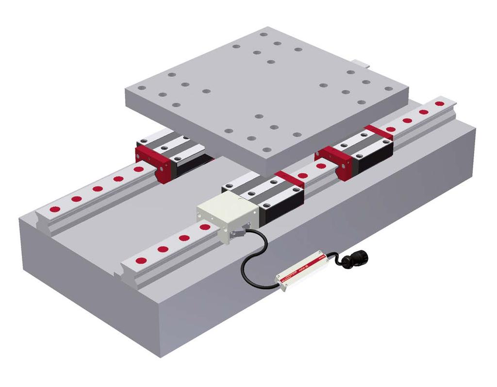
219 8 Commissioning 217
220 218
221 8 Contents 8 Commissioning Guideway check list Installation and checking system accuracy Supply of lubricant Corrosion protection Initial lubrication Lubrication plate SPL Measuring system check list
222 8 Commissioning 8.1 Guideway check list Installation and checking system accuracy Supply of lubricant Corrosion protection Initial lubrication 8.1. Guideway check list Before commissioning the guideway, it is important to ensure that the performance of the guideway is optimised by checking the following points: Guideway properly installed System accuracy and push force verified Supply of lubricant guaranteed Anti-corrosive protective device removed and guide rail oiled Initial lubrication completed Rail covers fitted and their seating has been checked Functionality of the wipers checked Functionality and correct seating of the bellows checked Installation and checking system accuracy After fitting the guideway in accordance with the MONORAIL and AMS installation instructions, system accuracy must be verified by measuring guide rail parallelism and running accuracy of the guideway or of the axis slide Supply of lubricant It is important to ensure that the supply of lubricant works properly. When the carriage is moving at the same time as the centralised lubricating system is working, a thin film of lubricant must be present on the guide rail and no leaks should occur within the lubrication system Corrosion protection When commissioning the guideway it is important to ensure that the factory-fitted anti-corrosive protective device on the guide rails is fully removed, see MONORAIL and AMS installation instructions, and that the guide rails are lightly moistened with the lubricant. A thin film of lubricant reduces the consumption of lubricant at the start of operation as any surface unevenness of the guide rail will be pre-filled with lubricant Initial lubrication Before commissioning the machine, initial lubrication of the carriages (other than in cases of carriages with full greasing in the factory) should be completed with oil, grease or fluid grease. Check the lubricants used for compatibility with factory preserving agents, coolants and other working materials. Initial lubrication can be dispensed with in case of factory-based full greasing of the carriages. When a centralised lubricating system is used ensure that the lubricating lines are properly connected and vented. Observe the system manufacturer's instructions. After initial lubrication check that the lubricant has reached the lubrication points in the carriage. When the carriage moves a significant film of lubricant must be visible on the tracks of the guide rail. Lubrication with grease With grease or fluid grease make sure that when greasing the carriages they are moved along the rail, ideally several times by 3 times the carriage length, or at least by the length of a single carriage. In the event that the maximum stroke is less than the carriage length, take note of Section Application know-how on lubrication - requirements in respect of lubrication in special operating conditions. 220 Lubrication with oil When lubricating with oil, the total quantity of oil should be injected in a single impulse or in several impulses in short succession while the carriage is actually being moved. In case of a specific installation orientation or short stroke, take note of the instructions set out in Section Application know-how on lubrication - requirements in respect of lubrication in special operating conditions.
223 8 Commissioning 8.1 Guideway check list Lubrication plate SPL Lubrication plate SPL Lubrication plates are always delivered ready for installation, i.e., filled with oil. When delivering together with a MONORAIL system or individual carriages, the carriages are also pre-filled with grease. When lubrication plates are retro-fitted, full greasing (LV) of the carriages is also necessary. For the recommended quantities of lubricant, see Section Lubrication with grease. For additional information about the lubrication plate SPL, see Section Lubrication. Rail covers The guide rail fixing holes must be fully closed with a cover strip or plugs and the closures must be fitted so that no dirt build up is able to form neither can the carriage wipers be damaged as a result. Cover strips must be placed on a clean guide rail surface without gaps and the ends must be secured with a fixing bracket or end pieces. Plugs must be fitted flush and parallel with the guide rail surface and there should not be any residual swarf or burrs. Wipers The wipers on the carriages and on the accessory components must be checked to ensure they are properly seated and work correctly: Standard wipers and additional wipers The function of the cross wipers is guaranteed when lubricant applied to the guide rail is cleanly wiped off and when the carriage reverses no streaking occurs on the guide rail surface that has been travelled over. Metal wipers The wipers must form an even gap around the guide rail profile and should not make any contact with the guide rail. Bellows When using bellows correct installation on to the adapter plate and end plate must be ensured, as well as its freedom of movement. 221
224 8 Commissioning 8.2 Measuring system check list 8.2. Measuring system check list Make sure that the performance of the measuring system is optimised by checking the following points: Carriage with housing is conveyed on the guide rail so that the recess for the reading head is located on the guide rail side with the scale. The scale side can be identified by the reference mark. Battery for AMSABS should be activated by removing the magnet on the electronics box. See Section Measuring system - AMSABS Reading head correctly installed in the housing, see additional documents. Cable and electronics box properly laid, see additional documents. Connection with the controller made. See Additional documents Section. LED for the operating state display (optional) is illuminated green after switching on the controller. 222

225 9 Operating, maintenance and service 223
226 224
227 9 Contents 9 Operating, maintenance and service Wipers Testing Replacement Influencing factors on operating conditions Environmental conditions Operating conditions Installation of the guideway Precautionary measures hour delivery service Objectives and sequence Products
228 9 Operating, maintenance and service 9.1 Wipers Testing Replacement 9.1. Wipers Testing Seals on SCHNEEBERGER MONORAIL guideways protect the carriages and the integral distance measuring system from penetration of foreign bodies in the form of solids or liquids and prevent the lubricant from discharging. Their functionality therefore influences the service life of the guideway significantly. In general, the seals are designed so that they are maintenance-free with sufficient lubrication and in a clean environment. Often, however, the guideways are used under conditions in which dust and swarf can get on to the guideway. This also inevitably leads to wear of the sealing lips, as with inadequate lubrication. The wipers on the front plates and additional wipers thus need to be checked for wear at regular intervals (maximum 6 monthly) and where applicable be replaced. Standard wipers and additional wipers The function check on cross wipers is carried out most simply using lubricant, which is applied to the guide rail. When propelling the machine slideway, the lubricant must be wiped off cleanly and when reversing over the guide rail surface that has already been passed over should not form any streaks. Otherwise the front plate (MR) and/or cross wipers (BM) or the additional wipers need to be replaced. Metal wipers Metal wipers like additional wipers and front plates need to be replaced in case of any visible mechanical damage Replacement Note In the case of MONORAIL BM, the front plate is part of the rolling element recirculating unit. Pulling off the front plate will lead to the loss of balls. Only the cross wipers QAS and not the complete front plate are replaced in this instance. With MONORAIL BM it is important to note that when replacing or retrofitting additional wipers or lubrication plates the front plate is secured to prevent it from coming away. Doing otherwise can lead to a loss of balls. Front plates and additional wipers can be individually re-ordered as spare parts. See Section Spare parts and the SCHNEEBERGER MONORAIL and AMS product catalogue. In case of damage to longitudinal wipers, which are mainly permanently connected with the carriage or housing (with integral distance measuring systems), the entire carriage will need to be replaced. Damage to longitudinal wipers can only usually be detected after complete uninstallation of carriage or housing components. When replacing front plates and additional wipers (ZCN/V and ZBN/V) the fastening screws of the front plates must be removed. In the case of MONORAIL MR, front plates should only be removed from the carriage for a replacement and the carriage should not be moved after removing the front plate. 226


229 9 Operating, maintenance and service 9.1 Wipers Replacement Always use an MRM assembly guide rail for rolling carriages on an off the guide rail. Additional information can be found in the MONORAIL and AMS installation instructions. Additional wipers Due to the flexibility of the additional wipers, they can be pulled over the top of the rail after removing the fixing screws. Installation is carried out in exactly the same way by putting it over the guide rail cross section or by driving over the guide rail end. As a result additional wipers can also be installed retrospectively, e.g. in the case of carriages on which the cross wipers of the front plate are closed and the carriages for replacement cannot be removed from the guide rail. Before tightening the screws, align the wiper using the centring cone on its back and ensure it is seated evenly. For the maximum tightening torque of screws, see the table section Permissible screw tightening torques. 227
230 9 Operating, maintenance and service 9.1 Wipers Replacement Metal wipers When replacing, undo the screws on the front plate and pull off the wiper at the end of the rail. Mount a new metal wiper over the guide rail end. To ensure reliable operation, the metal wipers require a consistent gap around the guide rail profile. This needs to be set during installation. For this purpose losely fix the fastening screws ensuring that the wiper can still be moved. Set the gap with a feeler gauge or similar device. Hold the metal wiper and tighten the fastening screws. For maximum torque, see table in the section Permissible screw tightening torques. Check the gap again after tightening the screws. MONORAIL MR front plates In the case of the front plates, the screw connection is undone and the front plate is pulled axially from the guide rail. The carriage should not be pushed in the process. Installation takes place in reverse order. When tightening fastening screws, observe maximum tightening torque in accordance with the section Permissible screw tightening torques. 228

231 9 Operating, maintenance and service 9.1 Wipers Replacement MONORAIL BM front plates In the case of MONORAIL BM, only the cross wipers in the front plate should be replaced. After driving the carriage off the guide rail using an assembly guide rail, the cross wipers can be pulled off downwards from the front plate housing. Insert new cross wipers into the guideway groove until the wiper audibly snaps into place. Then remount the carriages on to the guide rail. Permissible screw tightening torques Caution Component damage due to the reusing of fastening screws several times Do not re-use fastening screws several times. The screws are equipped with threadlocker. Its adhesion deteriorates when screwed in and out on numerous occasions, which can lead to unwanted loosening of the screws in operation. See the table below for the maximum tightening torques for fastening screws for the front plates and additional wipers. Maximum front plate tightening torque (Nm) MONORAIL BM Size M Anz BM BM 20 BM BM MONORAIL MR MR 25 MR MR MR 55 MR
232 9 Operating, maintenance and service 9.2 Influencing factors on operating conditions Environmental conditions Operating conditions Installation of the guideway 9.2. Influencing factors on operating conditions Environmental conditions The widest variety of environmental conditions occur for SCHNEEBERGER MONORAIL guideways from the large number of possible applications influencing the characteristics and service life of the guideway: Contamination of the carriages due to swarf and dust can be prevented by using additional wipers thereby increasing the operating period in dirty environments. When using coolants there is a risk that they wash out the lubricant from the guideway causing inadequate lubrication. This can also be successfully mitigated by additional wipers. Coolants can damage synthetic components due to chemical reactions or have a detrimental influence on the lubricant causing it, for example, to agglutinate. Moisture can drip onto the guide rails and carriages and lead to corrosion on metal components. This is prevented by the use of non-corrosive materials or corrosion-inhibiting coatings. SCHNEEBERGER offers a variety of hard chromium coatings and products in a stainless steel design. Temperatures outside the provided operating temperature result in changing the viscosity of the lubricating oil, which in the worse case scenario can lead to a break in the lubricating film Otherwise the mechanical characteristics of the plastics being used are only guaranteed within specific temperature limits. Another point are changes in length that occur in components in case of temperature variations. Differences in temperature between machine components can thus lead to stresses between guide rails and carriages due to different thermal expansion and cause high additional forces Operating conditions Inadequate lubrication leads to premature failure of the guideways. It is therefore important to ensure adequate and appropriate lubrication during operation of the linear guideway. Another parameter is the travelling speed, which should be within the specified limits. If it is permanently exceeded, the synthetic components in the recirculating units can be damaged. Short-stroke applications, where in a normal stroke not all the rolling elements enter the load zone, require special measures in terms of lubrication. Oscillations, vibrations and shock loads also reduce service life and need to be taken into consideration in their design due to corresponding factors Installation of the guideway The attainable service life is significantly influenced by the design configuration of the installation space and the arrangement of the guideway. These should be arranged so that the guideway itself as well as an integrated distance measuring system are protected as best as possible against the influence of dust, swarf and coolants. This includes the fact that measuring systems are basically fitted on the side pointing away from the working area. See Section Arrangement of the guideway. Another aspect is the accuracy of the connecting structure. Machine beds or stands can generate significant additional forces on the guideways due to deviations from the specified geometry, which in turn reduces service life. During installation of the guideways, constraining forces can occur due to poor alignment of components, which lead to a reduction in service life. 230
233 9 Operating, maintenance and service 9.3 Precautionary measures 9.3. Precautionary measures To maintain optimum operation of SCHNEEBERGER MONORAIL guideways over their entire service life, the following points need to be taken into account: Precision components are used in all SCHNEEBERGER guideways, which are preserved and packaged in the factory to optimal specifications. The systems need to be protected against impacts and humidity during transportation and storage. Instructions for transportation and installation are included with the measuring systems,which need to be observed. Installation of the guideways and the covering of the holes in the rails must be carried out by qualified staff. Instruction on installation are available from the Download area at www. schneeberger.com. The guideways should be adequately supplied with a lubricant adapted to a movement and load profile as well as the environmental conditions. In selecting a lubricant, we recommend that you contact a lubricant manufacturer directly. Lubrication recommendations can otherwise be obtained from The compatibility of coolants and lubricants needs to be checked by the user prior to commissioning to exclude the possibility of causing any negative influence on the guideway. The guideways should be protected from contamination, hot swarf and direct contact with coolants through covers or a suitable installation position. If the incidence of dirt or contact with coolant is expected during the operating phase of products, additional wipers should always be used. The functionality of these components over time is guaranteed by appropriate inspection intervals. Information on these products can be found at If the guideways come into contact with hot swarf, the use of metal wipers is also recommended. Information on these products can be found at The front wipers and the additional wipers for the MONORAIL carriages must be analysed at regular intervals for wear and replaced, where necessary. DIN 637 should always be observed when operating and dimensioning MONORAIL guideways. Furthermore DIN 637 is always valid even if contradictory statements are encountered within the DIN 637 document. 231
234 9 Operating, maintenance and service hour delivery service Objectives and sequence ProductsProducts hour delivery service Objectives and sequence With its 24-hr delivery service, SCHNEEBERGER offers the option of ordering MONORAIL guideways and AMS distance measuring systems as spare parts, e.g during a machine shut-down, at very short notice. To achieve this SCHNEEBERGER maintains its own semi-finished product warehouse of carriages, reading heads, guide rails and guide rails with integral scale. Enquiries and orders can be addressed directly to SCHNEEBERGER when required: Telephone No for enquiries to the 24-hr Service Department, working days from 7.30am to 5pm. Fax-No for orders Orders by post to the Service Department quoting Priority order for 24-hr Service Department. Orders for goods available from stock received before 10am can generally be dispatched on the same day. Orders received later are delivered within 24 hours Products SCHNEEBERGER offers a limited range of standard products for delivery as part of its 24-hr service. This includes: MONORAIL MR Guide rail type: N, Standard; C, Cover strip Carriage type: A, B, C and D Size: Accuracy class: G0 Preload: Average between V2 and V3 MONORAIL BM Guide rail type: N (ND), Standard; C, Cover strip Carriage type: A, B, C, D, E, F and G Size: Accuracy class: G0 Preload: Average between V2 and V3 MONORAIL AMS Guide rails with integral distance measuring system, accuracy class G0 Reading heads type AMS30, AMSA 3B, AMSD 3B, AMSA 4B and AMSD 4B Reading heads for older products and special guide rails on request. Detailed information on the products that can be supplied and prices can be obtained on request. 232


235 PROSPECTUSES COMPANY BROCHURE CUSTOMIZED BEARINGS GEAR RACKS LINEAR BEARINGS and RECIRCULATING UNITS MINERAL CASTING SCHNEEBERGER MINISLIDE MSQscale MINI-X MINIRAIL / MINISCALE PLUS / MINISLIDE MONORAIL and AMS profiled linear guideways with integrated measuring system MONORAIL and AMS application catalog POSITIONING SYSTEMS SLIDES
Ball Rail Systems RE / The Drive & Control Company
 Ball Rail Systems RE 82 202/2002-12 The Drive & Control Company Rexroth Linear Motion Technology Ball Rail Systems Roller Rail Systems Standard Ball Rail Systems Super Ball Rail Systems Ball Rail Systems
Profi le rail guides LLR
 Profi le rail guides LLR Content The SKF brand now stands for more than ever before, and means more to you as a valued customer. While SKF maintains its leadership as the hallmark of quality bearings throughout
Courtesy of CMA/Flodyne/Hydradyne Motion Control Hydraulic Pneumatic Electrical Mechanical (800)
") 01_1 Miniature st Headline_36 Ball Rail pt/14.4 Systems mm second line 2 Linear Motion and Assembly Technologies Miniature Ball Rail Systems Ball Rail Systems Roller Rail Systems Linear Bushings and Shafts
01_1 Miniature st Headline_36 Ball Rail pt/14.4 Systems mm second line 2 Linear Motion and Assembly Technologies Miniature Ball Rail Systems Ball Rail Systems Roller Rail Systems Linear Bushings and Shafts
R310EN 2302 ( ) The Drive & Control Company
 The Drive & Control Company") R31EN 232 (26.4) The Drive & Control Company Bosch Rexroth AG Linear Motion and Assembly Technologies Ball Rail Systems Linear Bushings and Shafts Ball Screw Drives Linear Motion Systems Basic Mechanical
R31EN 232 (26.4) The Drive & Control Company Bosch Rexroth AG Linear Motion and Assembly Technologies Ball Rail Systems Linear Bushings and Shafts Ball Screw Drives Linear Motion Systems Basic Mechanical
MINIRAIL Profiled miniature guideway
 MINIRAIL Profiled miniature guideway Table of Contents 1 Product overview and technical informations MINIRAIL a range of high-precision products.... 2 MINIRAIL overview accuracy classes:.... 3 MINIRAIL
Miniature Ball Rail Systems
 R310EN 2210 (2004.06) The Drive & Control Company 2 Bosch Rexroth AG Linear Motion and Assembly Technologies Miniature-BRS R310EN 2210 (2004.06) Linear Motion Systems Ball Rail System Standard Ball Rail
Contents. Page. 1. Product description. 2. The AXC line of linear axes. 3. AXLT line of linear tables. AXC and AXS product overview...
 SNR Industry Contents Page 3 1. Product description AXC and AXS product overview... 6-8 Dynamic load ratings of the linear motion systems... 9 Compact modules... 10-11 Linear tables... 12 Telescopic axes...
R310EN 2211 ( ) The Drive & Control Company
 The Drive & Control Company") eline Ball Rail Systems R310EN 2211 (2006.04) The Drive & Control Company Bosch Rexroth AG Linear Motion and Assembly Technologies Ball Rail Systems Roller Rail Systems Linear Bushings and Shafts Ball
eline Ball Rail Systems R310EN 2211 (2006.04) The Drive & Control Company Bosch Rexroth AG Linear Motion and Assembly Technologies Ball Rail Systems Roller Rail Systems Linear Bushings and Shafts Ball
Profile rail guides LLT
 Profile rail guides LLT Contents The SKF brand now stands for more than ever before, and means more to you as a valued customer. While SKF maintains its leadership as the hallmark of quality bearings throughout
series Linear guideways CG-serie 3.3 CG series
 series CG-serie 3.3 CG series 3.3.1 Properties of the linear guideways, series CG The HIWIN linear guideways of the CG series with O-arrangement of the ball tracks guarantee high torque loading capacity,
TELESCOPIC RAIL HEAVY
 TELESCOPIC RAIL HEAVY Every care has been taken to ensure the accuracy of the information contained in this catalogue, but no liability can be accepted for any errors or omissions. We reserve the right
EMC-HD. C 01_2 Subheadline_15pt/7.2mm
 C Electromechanical 01_1 Headline_36pt/14.4mm Cylinder EMC-HD C 01_2 Subheadline_15pt/7.2mm 2 Elektromechanischer Zylinder EMC-HD Short product name Example: EMC 085 HD 1 System = ElectroMechanical Cylinder
Precision Modules PSK
 Precision Modules PSK 2 Bosch Rexroth AG Precision Modules PSK R999000500 (2015-12) Identification system for short product names Short product name Example:: P S K - 050 - N N - 1 System = Precision Module
Precision Modules PSK
 Precision Modules PSK The Drive & Control Company Rexroth Linear Motion Technology Ball Rail Systems Roller Rail Systems Standard Ball Rail Systems Super Ball Rail Systems Ball Rail Systems with Aluminum
Slides. Dynamic and precise
 Slides Dynamic and precise Product catalog 2017 Latest version of the catalogs You can always find the latest version of our catalogs in the Download area of our website. Disclaimer This publication has
Ball Rail Systems BSCL. Ball Runner Blocks, Ball Guide Rails, accessories
 Ball Rail Systems BSCL Ball Runner Blocks, Ball Guide Rails, accessories 2 Ball Rail Systems BSCL General product information The Ball Rail System Compact Line BSCL The new Ball Rail System BSCL (Ball
...components in motion. Miniature Linear Guideways
 ...components in motion Miniature Linear Introduction Miniature linear guideway systems are widely used throughout industry for precise, compact applications. Precise and Stainless The gothic arch shape
Linear Motion Technology Handbook. The Drive & Control Company
 Linear Motion Technology Handbook The Drive & Control Company 1-2 Bosch Rexroth AG Linear Motion Technology Handbook R310EN 2017 (2006.07) Linear Motion and Assembly Technologies www.boschrexroth.com/brl
Axial-radial cylindrical roller bearings
 Axial-radial cylindrical roller bearings Designs and variants.............. 320 Bearing data..................... 321 (Boundary dimensions, tolerances) Product table 5.1 Axial-radial cylindrical roller
Easy Slide Rails ov -easy_slide_divider - U pdated
 Easy Slide Rails ov-easy_slide_divider - Updated - 18-09-2017 163 Easy Slide Rails Easy Slide Rails Introduction The Easy Slide family of linear rails have a compact cross-section and low-friction movement.
Guide units. For toolmaking, fixture manufacturing and machine engineering
 Guide units For toolmaking, fixture manufacturing and machine engineering Guide units in compliance with DIN, ISO and STEINEL standards or according to your specifications Guide pillars Guide and pillar
1. Product overview Basic-Line-Module AXN Product description Basic-Line-Module AXN 4-5. Guide system Roller guide 6 Drive system Gear belt 7
 Directory Page 1. Product overview Basic-Line-Module AXN 3 2. Product description Basic-Line-Module AXN 4-5 Guide system Roller guide 6 Drive system Gear belt 7 3. Basic-Line-Modul AXN 45-Z 8-9 AXN 65-Z
Compact Modules. with ball screw drive and toothed belt drive R310EN 2602 ( ) The Drive & Control Company
 The Drive & Control Company") with ball screw drive and toothed belt drive R310EN 2602 (2007.02) The Drive & Control Company Bosch Rexroth AG Linear Motion and Assembly Technologies Ball Rail Systems Roller Rail Systems Linear Bushings
with ball screw drive and toothed belt drive R310EN 2602 (2007.02) The Drive & Control Company Bosch Rexroth AG Linear Motion and Assembly Technologies Ball Rail Systems Roller Rail Systems Linear Bushings
Precision Modules PSK. The Drive & Control Company
 Precision Modules PSK The Drive & Control Company 2 Bosch Rexroth Coporation Precision Modules PSK R310A 2414 (2008.07) Linear Motion and Assembly Technologies Ball Rail Systems Roller Rail Systems Linear
Берг АБ Тел. (495) , факс (495)
 , факс (495)") AUTOMATION Linear- and Rotary Modules Table of Contents 1 Product Overview............................................. 4 1.1 Selection of the Linear Modules................................. 8 1.2 Selection
AUTOMATION Linear- and Rotary Modules Table of Contents 1 Product Overview............................................. 4 1.1 Selection of the Linear Modules................................. 8 1.2 Selection
Positioning Tables. Slides NFM NH2 - AL NE - AL
 Positioning Tables NFM NH2 - AL Slides NE - AL Product catalog 2017 Latest version of the catalogs You can always find the latest version of our catalogs in the Download area of our website. Disclaimer
Load Cell for Manually Operated Presses Model 8451
 w Technical Product Information Load Cell for Manually Operated Presses 1. Introduction... 2 2. Preparing for use... 2 2.1 Unpacking... 2 2.2 Using the instrument for the first time... 2 2.3 Grounding
NSK Linear Guides. Roller Guide RA Series. Extended series
 NSK Linear Guides A roller guide series employing advanced analysis technology offers super-high load capacity and rigidity. The RA series includes a complete lineup to handle a wide range of applications.
TRANSLATION (OR LINEAR)
") 5) Load Bearing Mechanisms Load bearing mechanisms are the structural backbone of any linear / rotary motion system, and are a critical consideration. This section will introduce most of the more common
5) Load Bearing Mechanisms Load bearing mechanisms are the structural backbone of any linear / rotary motion system, and are a critical consideration. This section will introduce most of the more common
TELESCOPIC RAILS HARDENED TELESCOPIC RAILS FOR HIGHLY DYNAMIC APPLICATIONS 7.1 PRODUCT OVERVIEW 7.2 PART EXTENSIONS 7.
 7 TELESCOPIC RAILS HARDENED TELESCOPIC RAILS FOR HIGHLY DYNAMIC APPLICATIONS PAGE 106 PAGE 116 PAGE 120 PAGE 126 7.1 PRODUCT OVERVIEW 7.2 PART EXTENSIONS 7.3 FULL EXTENSIONS 7.4 LINEAR GUIDES 105 PRODUCT
Miniature profi le rail guides
 Miniature profi le rail guides Contents The SKF brand now stands for more than ever before, and means more to you as a valued customer. While SKF maintains its leadership as the hallmark of quality bearings
Features of the LM Guide
 Features of the Functions Required for Linear Guide Surface Large permissible load Highly rigid in all directions High positioning repeatability Running accuracy can be obtained easily High accuracy can
Any reproduction, even partial, is allowed only by written permission by Rollco.
 EASYSLIDE Every care has been taken to ensure the accuracy of the information contained in this catalogue, but no liability can be accepted for any errors or omissions. We reserve the right to make changes
Toothed belt axis ELGC-TB-KF. Operating instruction [ ]
![Toothed belt axis ELGC-TB-KF. Operating instruction [ ]](/thumbs/83/87984161.jpg "Toothed belt axis ELGC-TB-KF. Operating instruction [ ]") Toothed belt axis ELGC-TB-KF en Operating instruction 8068220 2017-02 [8068222] Original instructions Identification of hazards and instructions on how to prevent them: Danger Immediate dangers which can
Toothed belt axis ELGC-TB-KF en Operating instruction 8068220 2017-02 [8068222] Original instructions Identification of hazards and instructions on how to prevent them: Danger Immediate dangers which can
Connection technology for Linear Motion Systems 1.3
 Connection technology for Linear Motion Systems 1.3 2 Connection technology for Linear Motion Systems 1.3 Connection technology for Linear Motion Systems 1.3 3 Contents 4 Combination options for -Z linear
TELESCOPIC-LINE. Semi-telescopic-rail LST. Telescopic-rail LSE. Linear guides with ball-cage LSS
 TELESCOPIC-LINE Semi-telescopic-rail LST Telescopic-rail LSE Linear guides with ball-cage LSS 1 Ball rails LSS, LST and LSE The ball rails produced by Nadella are very compact and flexible products. Made
Components for parallel kinematics
 Components for parallel kinematics Series GLK, GLAE Joints and struts form the core components of machines with parallel kinematics (PKM). Irrespective of the control technology possibilities, good mechanical
Dynamic Elements Linear Slides Mechanical Drive Elements Accessories for Mechanical Drive Elements
 8 Dynamic Elements Mechanical Drive Elements Accessories for Mechanical Drive Elements The Dynamic Elements product group of the MB Building Kit System contains components which enable precise linear movement.
General Technical Data and Calculations
 12 Bosch Rexroth AG R310EN 2202 (2009.06) General Product Description General Technical Data and Calculations General notes The general technical data and calculations apply to all, i.e., to all ball runner
...components in motion. Easy Rail
 ...components in motion Easy Rail Easy Rail Introduction The Easy Rail family have a compact cross-section and low-friction movement. Robust and Long Service Life Easy Rail s range of cross-sectional rail
SNR, YOUR GUIDE TO LINEAR MODULES
 SNR, YOUR GUIDE TO LINEAR MODULES A bearing manufacturer known across the world For almost a century NTN-SNR has been focusing on the development, design and manufacture of bearings. Today NTN-SNR has
Linear Bushings and Shafts
 Linear Bushings and Shafts 45 b 1cr RA 83 100.1 Linear Motion and Assembly Technologies STAR Linear Motion Technology Ball Rail Systems Standard Ball Rail Systems Ball Rail Systems with Aluminum Runner
Product overview. 10 Bosch Rexroth Corporation Compact Modules R310A 2602 ( ) Compact Modules CKK. Compact Modules with ball screw drive (CKK)
 Compact Modules CKK. Compact Modules with ball screw drive (CKK)") 10 Bosch Rexroth Corporation R310A 2602 (2008.09) CKK with ball screw drive (CKK) Product overview are precision, ready-to-install linear motion systems characterized by their high performance and compact
10 Bosch Rexroth Corporation R310A 2602 (2008.09) CKK with ball screw drive (CKK) Product overview are precision, ready-to-install linear motion systems characterized by their high performance and compact
Assemblies for Parallel Kinematics. Frank Dürschmied. INA reprint from Werkstatt und Betrieb Vol. No. 5, May 1999 Carl Hanser Verlag, München
 Assemblies for Parallel Kinematics Frank Dürschmied INA reprint from Werkstatt und Betrieb Vol. No. 5, May 1999 Carl Hanser Verlag, München Assemblies for Parallel Kinematics Frank Dürschmied Joints and
Tension and Compression Load Cell Model 8435
 Technical Product Information w Tension and Compression Load Cell 1. Introduction... 2 2. Preparing for use... 2 2.1 Unpacking... 2 2.2 Using the instrument for the first time... 2 2.3 Grounding and potential
TRACK GUIDANCE SYSTEMS
 EURO-BEARINGS LTD TRACK GUIDANCE SYSTEMS www.euro-bearings.com Tel. 01908 511733 email: sales@euro-bearings.com INTRODUCTION EURO-BEARINGS LTD www.euro-bearings.com Tel. 01908 511733 This linear guidance
MONORAIL AND AMS. Lubrification pages Dimensioning pages Design and installation pages Precautinary Measures page 125
 MONORAIL AND AMS Lubrification pages 21-31 Dimensioning pages 104-111 Design and installation pages 112-124 Precautinary Measures page 125 3.7 Lubrication As delivered condition Lubrication connections
PRECISION BELLOWS COUPLINGS
 PRECISION BELLOWS COUPLINGS Bellows couplings are used where precise rotation, high speeds, and dynamic motion must be transmitted. They exhibit zero backlash and a high level of torsional stiffness, offering
A superior alternative to hydraulic or pneumatic motion providing 15 times the life of a ball screw. Planetary Roller Screws
 A superior alternative to hydraulic or pneumatic motion providing 15 times the life of a ball screw Planetary Roller Screws Exlar Your Linear Motion Experts Exlar Corporation is committed to providing
eline Profiled Rail Systems
 eline Profiled Rail Systems with Ball and Cam Roller Runner Blocks R310EN 2211 (2008.04) The Drive & Control Company Bosch Rexroth AG Linear Motion and Assembly Technologies Ball Rail Systems Roller Rail
Linear Drive with Ball Screw Drive Series OSP-E..SB
 Linear Drive with Ball Screw Drive Series OSP-E..SB Contents Description Data Sheet No. Page Overview 1.30.001E 47-50 Technical Data 1.30.002E-1 to 5 51-55 Dimensions 1.30.002E-6, -7 56-57 Order instructions
Linear Drive with Toothed Belt and Integrated Guide with Recirculating Ball Bearing Guide with Roller Guide Series OSP-E..BHD
 Linear Drive with and Integrated Guide with Recirculating Ball Bearing Guide with Roller Guide Contents Description Page Overview 11-14 Version with Recirculating Ball Bearing Guide Technical Data 15-17
INDEX EASY RAIL: THE SOLUTION IS EASY...D4 EXAMPLES OF LOAD CAPACITIES...D5 ORDER CODES...D6 MOUNTING EXAMPLES...D7 TECHNICAL DATA...
 INDEX EASY RAIL: THE SOLUTION IS EASY...D4 EXAMPLES OF LOAD CAPACITIES...D5 ORDER CODES...D6 MOUNTING EXAMPLES...D7 TECHNICAL DATA...D8 STANDARD CONFIGURATIONS...D10 VERIFICATION UNDER STATIC LOAD...D12
ELGC-BS-KF. Spindle axis. Instructions Operating c [ ]
![ELGC-BS-KF. Spindle axis. Instructions Operating c [ ]](/thumbs/88/115778972.jpg "ELGC-BS-KF. Spindle axis. Instructions Operating c [ ]") ELGC-BS-KF Spindle axis Instructions Operating 8095590 8095590 2018-08c [8095592] Translation of the original instructions 2 Festo ELGC-BS-KF 2018-08c Table of contents 1 Further applicable documents...
ELGC-BS-KF Spindle axis Instructions Operating 8095590 8095590 2018-08c [8095592] Translation of the original instructions 2 Festo ELGC-BS-KF 2018-08c Table of contents 1 Further applicable documents...
ORIGA Pneumatic Linear Drives OSP-L
 ORIGA Pneumatic Linear Drives OSP-L Very long lifetime and lowest leakage A NEW Modular Linear Drive System With this second generation linear drive Parker Origa offers design engineers complete flexibility.
LOCKED SERIES. Machine Failures. General Information. set up. maintenance. reconditioning. repair 30.4%
 General Information LOCKED SERIES 2 Lowering machinery process costs is key in today s world. According to a recent study approximately a third of all machine stoppages result in unexpected damage and
STAR Ball Rail Tables TKK
 before operating X4 X8 X3 X1 X2 S1 S2 12 4 13 5 14 6 15 7 16 8 1 2 3 9 10 11 1 2 3 4 5 6 8.8 S3 X30 Indramat DANGER! AC-CONTROLLER High voltage Danger of electrical shock Do not touch electrical connnections
Components for parallel kinematics
 Components for parallel kinematics Series GLK, GLK 2, GLK 3 and GLAE Parallel kinematic components consist of a number of parallel, longitudinally adjustable mechanical struts that are arranged between
Ball. Ball cage. Fig.1 Structure of Caged Ball LM Guide Actuator Model SKR
 Caged all LM Guide Actuator Model Inner block all screw shaft Grease nipple Outer rail all cage all Structure and Features Fig.1 Structure of Caged all LM Guide Actuator Model Caged all LM Guide Actuator
Table of Contents 1 Product Overview... L 4
 Table of Contents 1 Product Overview............................................ L 4 2 Applications 2.1 Linear Bearings for a Universal Tool Grinding Machine Table......... L 12 2.2 Grinding Table Mounting
506E. LM Guide Actuator General Catalog
 LM Guide Actuator General Catalog A LM Guide Actuator General Catalog A Product Descriptions 506E Caged Ball LM Guide Actuator Model SKR.. A2-4 Structure and Features... A2-4 Caged Ball Technology... A2-6
Ball screw drives KGT General technical data
 KGT General technical data Manufacturing process The thread profile is produced by cold rolling in the thread rolling method. Both screw and nut have a gothic thread profile. The load angle is 45. Linear
10 Thrust ball bearings
 10 Thrust ball bearings Designs and variants.............. 1010 Single direction thrust ball bearings... 1010 Double direction thrust ball bearings.. 1010 Cages............................ 1010 Bearings
Linear Guideways ov -linear -guidew ays-divider - U pdated
 Linear Guideways ov-linear-guideways-divider - Updated - 11-01-2017 163 Linear Guideways Linear Guideways Introduction L1016 Linear guideways Linear guideways are widely used throughout industry for heavy-duty
1.1 UNITS AND DEFINITIONS 12
 PRODUCT TECHNOLOGY 11 TABLE OF CONTENTS 1.1 UNITS AND DEFINITIONS 12 1.2 PRECISION AND TOLERANCES 13 1.2.1 Qualities 13 1.2.2 Profile tolerances 13 1.2.3 Lengths, hole distances 13 1.2.4 Matching 14 1.2.5
Features of the LM Guide
 Features of the Functions Required for Linear Guide Surface Large permissible load Highly rigid in all directions High positioning repeatability Running accuracy can be obtained easily High accuracy can
Linear Actuator with Toothed Belt Series OSP-E..B
 Linear Actuator with Toothed Belt Series OSP-E..B Contents Description Data Sheet No. Page Overview 1.20.001E 21-24 Technical Data 1.20.002E-1 to 5 25-29 Dimensions 1.20.002E-6 30 Order Instructions 1.20.002E-7
RE / STAR Tolerance Rings STAR Ball Knobs, Knob and Lever Type Handles
 RE 2 970/.99 STAR Tolerance Rings STAR Ball Knobs, Knob and Lever Type Handles STAR Tolerance Rings Product Overview Tolerance rings are made of hard, embossed spring steel strip and belong to the class
Inner block. Grease nipple. Fig.1 Structure of LM Guide Actuator Model KR
 LM Guide ctuator Model LM Guide + all Screw = Integral-structure ctuator Stopper Housing all screw Inner block Grease nipple Outer rail earing (supported side) Housing Stopper Double-row ball circuit earing
Integral tapered roller bearings Series JK0S
 Integral tapered roller bearings Series JK0S Technical Product Information Features Features FAG integral tapered roller bearings JK0S are ready-to-fit, easily mounted units. The single row bearings are
Product Description. Characteristic features R310A 2402 ( ) Linear Modules MLR
 Linear Modules MLR") 9 Bosch Rexroth Corporation R310A 40 (1.11) MLR Product Description Characteristic features MLR...: with Cam Roller Guide and Toothed Belt Drive for high-speed applications (up to 10 m/s) with Cam Roller
9 Bosch Rexroth Corporation R310A 40 (1.11) MLR Product Description Characteristic features MLR...: with Cam Roller Guide and Toothed Belt Drive for high-speed applications (up to 10 m/s) with Cam Roller
Main Catalogue. EichenbergerGewinde. 100 % Swiss made
 EichenbergerGewinde 100 % Swiss made Main Catalogue Carry ball screws Carry Speed-line high-helix ball screws Speedy high-helix lead screws Rondo round thread lead screws The choice is yours Thread rolling
Planetary Roller Type Traction Drive Unit for Printing Machine
 TECHNICAL REPORT Planetary Roller Type Traction Drive Unit for Printing Machine A. KAWANO This paper describes the issues including the rotation unevenness, transmission torque and service life which should
Linear Bushings and Shafts. The Drive & Control Company
 Linear Bushings and s The Drive & Control Company 2 Bosch Rexroth Corp. Linear Motion and Assembly Technologies Linear Bushings R310A 3100 Linear Motion Technology Ball Rail Systems Standard Ball Rail
The Classification Chart of PMI Linear Guideways
 1 The Characteristics of MI s The Classification Chart of MI s 2 (1) igh positioning accuracy, high repeatability The MI linear guideway is a design of rolling motion with a low friction coefficient, and
Instructions for Miniature Ball Rail Systems
 Industrial Hydraulics Electric Drives and Controls Linear Motion and Assembly Technologies Pneumatics Service Automation Mobile Hydraulics Instructions for Miniature Ball Rail Systems The Drive and Control
High precision bearings for combined loads
 High precision bearings for combined loads Axial/radial bearings Axial angular contact ball bearings Axial/radial bearings with integral angular measuring system The right product for every application
WIESEL SPEEDLine WHZ80 with roller guideway and AT toothed belt
 WIESEL WHZ80 with roller guideway and AT toothed belt All figures shown in millimeters. Note: Mounted wipers on request. The use of a long power bridge increases the total length. Technical data Linear
Any reproduction, even partial, is allowed only by written permission by Rollco.
 LINEAR UNIT E-SMART Every care has been taken to ensure the accuracy of the information contained in this catalogue, but no liability can be accepted for any errors or omissions. We reserve the right to
Linear Guideways HG Series
 18 G99TE1-67 Linear Guideways 2-1 - Heavy Load Ball Type Linear Guideway HG series linear guideways are designed with load capacity and rigidity higher than other similar products with circular-arc groove
BEVEL GEAR UNITS ZZ-SERVOLINE
 BEVEL GEAR UNITS ZZ-SERVOLINE ZZ-SERVOLINE GEARBOX DESIGN AND FUNCTIONAL FEATURES Gear Ratios i= 3:1 i= 4:1 i= 5:1 i= 6:1 i= 8:1 i= 10:1 i= 12:1 i= 15:1 Spiral Bevel Gear KLINGELNBERG tooth system Hypoid
Slotted nut NMG. Housing nut GWR. Bosch Rexroth AG. for economical constructions. a min. 0,3. M A = tightening torque of slotted nut.
 R310EN 3301 (2009.08) Precision Ball Screw Assemblies Bosch Rexroth AG 113 Slotted nut NMG for economical constructions B D d d1 b M A = tightening torque of slotted nut a min. 0,3 Polyamide insert Designation
Shaft-Hub-Connections
 Stand: 14.01.2010 Shaft-Hub-Connections Shrink Discs Cone Clamping Elements Star Discs 36 Edition 2012/2013 RINGSPANN Eingetragenes Warenzeichen der RINGSPANN GmbH, Bad Homburg Table of Contents Introduction
SKF Miniature Profile Rail Guides
 Linear Motion SKF Miniature Profile Rail Guides The SKF Group The SKF Group is an international industrial corporation of AB SKF Sweden, founded in 1907, operating in 130 countries. The company has some
Linear Actuator with Ball Screw Series OSP-E..S. Contents Description Overview Technical Data Dimensions 89
 Linear Actuator with Ball Screw Series OSP-E..S Contents Description Page Overview 79-82 Technical Data 83-88 Dimensions 89 79 The System Concept ELECTRIC LINEAR ACTUATOR FOR HIGH ACCURACY APPLICATIONS
ISO INTERNATIONAL STANDARD. Rolling bearings Sleeve type linear ball bearings Boundary dimensions and tolerances
 INTERNATIONAL STANDARD ISO 10285 Second edition 2007-11-01 Rolling bearings Sleeve type linear ball bearings Boundary dimensions and tolerances Roulements Roulements linéaires à recirculation de billes,
Proven to be better. Development trends in industrial rolling bearings
 Proven to be better Development trends in industrial rolling bearings Contents 1. General trends in power transmission and in machine construction and plant engineering Page 3 2. General trends in rolling
LM Guide Radial Type Model SR
 LM Guide Radial Type Model Endplate LM block Grease nipple End seal LM rail 90 Ball Retainer plate Side seal (Optional) Cross section 30 Point of Selection A Point of Design Options Model No. Precautions
Installation and Operational Instructions for EAS - HTL housed overload clutch Sizes 01 3 Type 490._24.0
 Please read these Operational Instructions carefully and follow them accordingly! Ignoring these Instructions may lead to malfunctions or to clutch failure, resulting in damage to other parts. Contents:
Linear Guideways RG/QR series
 CRD Devices Ltd All Saints Industrial Estate, Shildon, Co, Durham, DL4 2RD Tel: +44 (0)1388 778400 Fax: +44 (0)1388 778800 E: sales@crd-devices.co.uk W: www.crd-devices.co.uk 1.7 Linear Guideway Series
Heavy-Duty Rod Ends - Male with integral spherical plain bearing
 Heavy-Duty Rod Ends - Male with integral spherical plain bearing 65700 Order No. Thread (hand) d 1 l 1 d 2 d 3 d 4 l 2 l 3 X g H7 65700.W0005 Right 5 33 M 5 11,11 18 20 9 14 65700.W0006 Right 6 36 M 6
LINEAR RAIL BALL CHAIN TYPE
 LINEAR RAIL BALL CAIN TYPE Svanemærket tryksag 54-73 INDEX Index Product overview... 4-5 Dimension table RC/ERC... 6-7 Dimension table RC... 8-9 Dimension table ARC... 0-3 Dimension table & Grease... 4
ndustr SNR our guide to linear modules
 ndustr SNR our guide to linear modules SNR A bearing manufacturer known across the world For almost a century SNR has been focusing on the development, design and manufacture of bearings. Today SNR has
High Precision Bearings for Combined Loads
 High Precision Bearings for Combined Loads Axial/radial bearings Axial angular contact ball bearings Axial/radial bearings with angular measuring system added competence for your success With their forward-looking
V SWISS MADE LINEAR TECHNOLOGY
 Compact units Excerpt from main catalogue SWISS MADE LINEAR TECHNOLOGY V 11-15 Line Tech compact units Table of contents Product overview 106 107 Design fundamentals / Lubrication / Maintenance 108 Profile
Installation and Operational Instructions for EAS -Compact overload clutch, Type 49_. 4._ Sizes 4 and 5
 Please read these Operational Instructions carefully and follow them accordingly! Ignoring these Instructions may lead to malfunctions or to clutch failure, resulting in damage to other parts. Contents:
Linear Bushings and Shafts
 Linear Bushings and s R310EN 3100 (2004.09) The Drive & Control Company R310EN 3100 (2004.09) Linear Bushings Bosch Rexroth AG 3 Linear Bushings and s Selection Guide 9 Product Overview 10 Overall Dimensions
3. BEARING ARRANGEMENT DESIGN
 3. BEARING ARRANGEMENT DESIGN 3.1 GENERAL PRINCIPLES OF ROLLING BEARING ARRANGEMENT DESIGN Rotating shaft or another component arranged in rolling bearings is guided by them in radial as well as in axial
VBK 2596/12E/RSF. Thickness and Width Gauge for Strip and Profile. Operating- & Service Instructions. (with lateral guide rollers)
") Thickness and Width Gauge for Strip and Profile (with lateral guide rollers) VBK 2596/12E/RSF Operating- & Service Instructions erstellt am 5.2.1998 freigegeben am Bemerkungen Rev.01 Seiten:16 Name: Rietdorf
Thickness and Width Gauge for Strip and Profile (with lateral guide rollers) VBK 2596/12E/RSF Operating- & Service Instructions erstellt am 5.2.1998 freigegeben am Bemerkungen Rev.01 Seiten:16 Name: Rietdorf
2-9 RG Series High Rigidity Roller Type Linear Guideway
 G99TE17-136 2-9 High Rigidity Roller Type Linear Guideway 2-9-1 Advantages and features The new RG series from Hiwin features a roller as the rolling element instead of steel balls. The roller series offers