Read Me At a Glance Getting Started Display Setup Settings Performance Settings Diagnostics
|
|
|
- Cory Conley
- 5 years ago
- Views:
Transcription

1
2 Table of Contents Read Me 4...Safety Warning and Caution 5...Safety Guidelines At a Glance 6...Physical Overview - The Display 7...Accessories 8...Touch Screen Gestures 9...Menu Icons 9...Common Terms Getting Started 10...Download the Fusion Update Software 11...Using the Fusion Update Software 12...Cable Installation 12...Windshield Mount Installation 13...Installing the Display Display Setup 14...Download and Install MyStyle Software 15...Adding Custom Background Images 16...Entering the Quick Link Menu 17...Entering the Pull Down Menu 18...Changing the Default Background Image 19...Individual Gauge Setup 20...Configuring the Home Screens 22...Calibrating Pitch, Roll, & G-Force Gauges 23...Using the Off Road Screen 24...Using the Switch Screen - Quick Features 26...Using the Switch Screen - Toggle Switches Settings 28...Accessory Settings 30...Alert Settings 31...Sound Duration - Alerts 31...Backlight Auto dim 32...Menu Time out 32...Vehicle Weight 32...Units 33...Unlock TPMS Control 33...Show Swipe Tutorial Off 33...Calibrate Accelerometer 33...Factory Reset Performance Settings 34...Basic Programming 36...Custom Vehicle Programming 38...Power Levels Explained 39...Custom Options Explained Diagnostics 40...Read DTCs 41...Clear DTCs
3 Performance Testing & Quarter Mile 43...Horsepower Data Log 44...Data Logging Explained 45...Retrieving Data Using MyStyle Records 46...Records Explained Help 47...Help Menu Explained Maintenance Manager 48...Turn on Maintenance Manager 49...Entering the Odometer Value 50...Setting the Alert Threshold 51...Customizing Maintenance Items Mileage Coach 52...Mileage Coach Set Up Appendix 54...Limited 1 Year Warranty 55...Important Information about your Vehicle s Warranty 56...Service Center and Compatibility Cautions 57...Tips 57...CARB/EPA Compliance 58...Trouble Shooting
4 Read Me Safety Warning and Caution Throughout this User Manual you will see important messages regarding your safety or the protection of your vehicle. These messages are designated by the words WARNING or CAUTION. WARNING indicates a condition that may cause serious injury or death to you, your passengers or others nearby. Pay careful attention to these Warning messages, and always comply with them. They could save a life. CAUTION indicates a condition that could cause damage to your vehicle. It is important to install and operate your product in conformance with instructions in this Manual. Caution alerts you to particularly important things that will keep your vehicle operating properly. The product you have purchased is a high-performance product. As such, it does present some risks of which you should be fully aware. Do not use this product until you have carefully read the following safety information and the Owner Agreement. NOTE: After the display has been installed, a warning screen will appear (3) different times. WARNING: Misuse of this device could lead to a serious accident. Do not use to break legal speed limits. Before installing, read and comply with all information in the User Guide. Do you agree? If you agree with the agreement, select Yes to continue. 4
5 Safety Guidelines 1. Do not exceed legal speed limits on public roadways. Use any enhanced speed capabilities of this product only in closed circuit, legally sanctioned racing environments expressly for this purpose. Loss of control from speeding on a public road could seriously injure you, your passengers, or others on the roadway. 2. Do not operate the device while driving. Perform all adjustments or changes while stopped. Changing a setting while under way can interfere with your attention to roadway conditions. 3. Stacking performance-enhancing devices or other improper installation can cause power train failure on the road. Other products may have features incompatible with your Superchips device. Follow all installation and operating instructions, and do not stack products. 4. Some modifications may affect other parts of your vehicle. For example, if you remove/adjust the speed limiter in your vehicle, be sure your tires and other components are rated for the increased speeds they will have to withstand. Not doing so can lead to loss of vehicle control. Modify the speed limiter only for use in closed circuit, legally sanctioned racing environments, not for use on public roadways. WARNING - Misapplication or misuse of this product could lead to a serious or fatal accident. Comply with all safety information in this manual, and your vehicle owner s manual. Follow safety, installation and operating instructions in this User Manual to assure proper use. 5


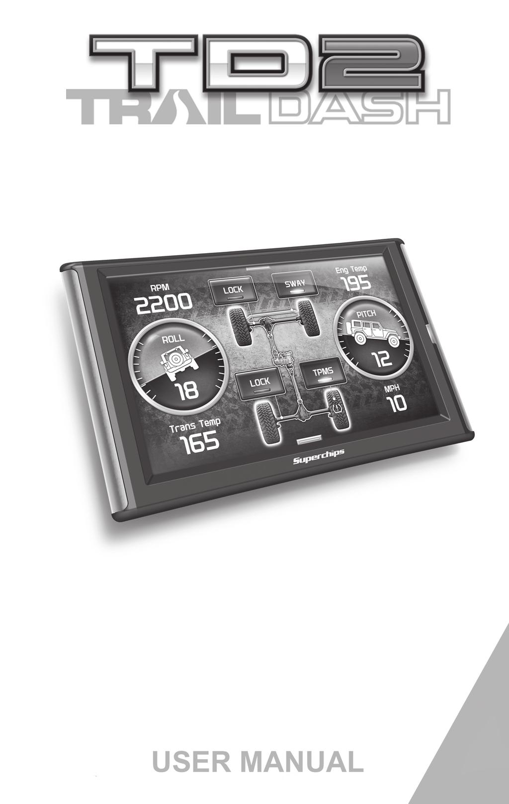
6 At a Glance Physical Overview - The Display Drop-down Menu Gauges Ambient Light Sensor Quick Link Menu Video In HDMI Port Mini USB port Mount Receiver 6 At a Glance


7 Accessories Windshield Mount Alcohol Wipe Isopropyl Mini USB Cable Zip-Ties OBDII to HDMI cable HDMI EAS OBDII At a Glance 7

8 Touch Screen Gestures Use these gestures to navigate and control the display. Press Hold & Drag The Press gesture is used to select options, input values, enter menus, etc. The Hold & Drag gesture is used to drag up or down menus, and scroll through menu items. Swipe The Swipe gesture is used to scroll through gauge screens. 8 At a Glance
9 Menu Icons Icon Home Background Custom Color Default Color Back What it does Brings you back to the home screen Changes the background Image Opens the custom color picking menu Opens the default color picking menu Brings you back to the previous screen or menu Common Terms Term PID - Parameter IDs EAS - Expandable Accessory System ECM - Engine Control Module TCM - Transmission Control Module PCM - Power Control Module What it is Data taken from a vehicle & viewed in a gauge Allows you to connect aftermarket sensors and other devices such as turbo timers (aka ECU) A computer that controls various sensors and engine components (aka TCU) A computer that controls automatic transmissions (aka PCU) Combines and provides power for the ECM and TCM At a Glance 9
10 Getting Started Download the Fusion Update Software A computer with internet access is required: STEP 1 - Go to STEP 2 - Click the UPDATES tab, then DOWNLOAD Fusion. STEP 3 - Open the FusionClientSetup.exe file, then click Run. STEP 4 - Click Next to begin. STEP 5 - Choose a folder location, then click Next to continue. STEP 6 - Click Next to confirm the installation. STEP 7 - Click the OK button if during the installation, the following message appears: These drivers are not Windows Logo or WHQL verified. If you are asked, please choose to install them anyway. STEP 8 - Click Close to exit once the installation is complete. STEP 9 - Double click the Fusion Icon on your desktop. STEP 10 - Click on the Create a New User option. STEP 11 - Fill in the required information and click Save. An containing your fusion password will be sent to the you used in the form. Use this password to login into Fusion. (NOTE: The password is case sensitive) STEP 12 - Double click the Fusion Icon on your desktop. STEP 13 - Plug the display into the computer using the USB cable. STEP 14 - If asked, choose Yes, this time only, then click Next. STEP 15 - Select Install the software automatically then Next. STEP 16 - If you re asked to Continue Anyway or STOP installation click Continue Anyway then click Next to complete the hardware wizard. 10 Getting Started


11 Using the Fusion Update Software A computer with internet access is required: STEP 1 - Double click the Fusion Icon on your desktop. STEP 2 - When asked, plug the display into the computer using the supplied USB cable. STEP 3a - If an update is available, click YES to continue. DO NOT unplug the display from the computer during an update. STEP 3b - If an update is not available, click the OK button. STEP 4 - Once the update is complete, click Close. Getting Started 11


12 Cable Installation STEP 1 - Locate the On Board Diagnostics II (OBDII) port. (This connector is typically found directly below the driver side dash console.) STEP 2 - Plug the OBDII connector into the vehicle port. STEP 3 - Route the HDMI end up the driver side dash. (On most vehicles, the side panel may be removed to expose the underside of the dash for easier routing. Leave exposed until after the display is installed.) EAS HDMI OBDII Windshield Mount Installation STEP 1 - Use the Alcohol Wipe to liberally clean the windshield in the area you plan to place the suction cup. Allow the glass to fully dry. STEP 2 - Firmly press and hold the suction mount against the glass. STEP 3 - Rotate the Cam Lever towards the glass to create the suction. 12 Getting Started


13 Installing the Display STEP 1 - Plug the HDMI connector into the HDMI receptacle located on the back side of the display. STEP 2 - Align the Dual Tabs on the Mount with the mount receiver on the back side of the display, then slide it into place. STEP 3 - Adjust the viewing angle using the adjustment nut on the mount s swivel head. STEP 4 - Pull any extra cable back behind the pillar and dash. (Re-install any panels removed during the Cable Installation.) Getting Started 13


14 Display Setup Download and Install MyStyle Software MyStyle is software that allows you to customize your display background image and manage your EAS devices. A computer with internet access is required: STEP 1 - Go to STEP 2 - Click the UPDATES tab, then Mystyle DOWNLOAD. STEP 3 - Open the MyStyleSetup.exe file, then click Run. STEP 4 - Click Next to begin. STEP 5 - Choose a folder location, then click Next to continue. STEP 6 - Click Next to confirm the installation. STEP 7 - Click the OK button if during the installation, the following message appears: These drivers are not Windows Logo or WHQL verified. If you are asked, please choose to install them anyway. STEP 8 - Click Close to exit once the installation is complete. 14 Display Set Up

15 Adding Custom Background Images This section describes how to add personalized photos or pictures to your display using a computer. STEP 1 - Double-click the MyStyle icon on your desktop. STEP 2 - Connect the display using the supplied USB cable. When a display is plugged in, an image of the display will appear with a 9 digit number. STEP 3 - Click the image of your display. STEP 4 - Choose to Customize the Display. STEP 5 - Select an Image to replace. STEP 6 - Select the Open Image button. STEP 7 - Use the available tools to size and align your image. STEP 8 - Click the Save Background button to save your progress. This will also save the new background image to you display. Display Set Up 15
16 Entering the Quick Link Menu STEP 1 - Press the lower menu tab to enter the Quick Link Menu. STEP 2 - The Main Menu will appear. Choose a menu option, and Press the Icon to enter that feature menu. (Note: Each feature menu option is shown in detail later in this manual) Return to Home Screen Display Set Up 16
17 Entering the Pull Down Menu STEP 1 - Press the upper menu tab to enter the Pull Down Menu. The following screen will appear: If notifications are active they will be listed here. If multiple notifications are active at one time they will alternate every few seconds. Light Indicator These buttons toggle the power level which is displayed between the two. Change Background Image Return to Home Screen Adjust Background Color & Opacity When the Drop Down menu is closed, this tab alerts you to any notifications that are available by changing color. Display Set Up 17


18 Changing the Default Background Image STEP 1 - Enter the Pull Down Menu. STEP 2 - Press the Background icon. Each press of the icon will cycle through to the next image: Tracks Honey Comb Moab Carbon Fiber Sand Camouflage Cement Desert Tread Old Barn 18 Display Set Up Refer to the Adding Custom Background Images section of this manual for information on how to add your own images to the display.

19 Individual Gauge Setup STEP 1 - Press any gauge. STEP 2 - Select New PID Some Analog gauges allow you to change its color Describes the selected PID Battery Voltage Select New PID Alert Settings Gauge Color PID Information Exit Menu Please Refer to Alert Options Section for more info STEP 3 - Press the Up/Down arrows to locate a new PID. Select a new PID. PID Select Menu Manifold Abs Pressure Mass Air Flow Mileage Avg. Mileage Inst. Mileage Coach STEP 4 - Return Home. The new PID will be displayed on the gauge you selected. Display Set Up 19
20 Configuring the Home Screens STEP 1 - Enter the Quick Link menu. STEP 2 - Press the Screen Layout Icon STEP 3 - Select the a DAQ screen option Screen Layout Background DAQ Screen 1 - Master DAQ Screen 2 - Accelerometer Press to select a default Background image STEP 4 - Select one of the screen layout options Screen Layout Master Digital Retro Needles Accelerometer Rubicon 20 Display Set Up


21 Master Gauge Digital Gauges Retro Gauge Needle Gauges Accelerometer Gauges Rubicon Gauges Switch Screen The Switch Screen is an additional layout. Continue with steps 5 & 6 below until the Switch Gauges are shown. STEP 5 - Return to the Home screen. STEP 6 - Swipe horizontally to switch between your selected layouts. Display Set Up 21

22 Calibrating Pitch, Roll, & G-Force Gauges Once the display has been installed, and is mounted in a semipermanent position, the Pitch, Roll, & G-Force gauges will need to be calibrated. STEP 1 - Refer to Configuring the Home Screen section in this manual. Assign the Accelerometer screen layout to one of the DAQ screens. STEP 2 - Once the Accelerometer Gauge is displayed, enter the Quick Link menu. STEP 3 - Press the Settings STEP 4 - Press the Up/ Down arrows until the Calibrate Accelerometer option is available. STEP 5 - Press the Calibrate Accelerometer option. icon. Settings Calibrate Accelerometer Units: English Unlock TPMS Control Factory Reset STEP 6 - Return home to the gauge screen. The Pitch, Roll, & G-Force gauges should all read zero. 22 Display Set Up


23 Using the Rubicon Screen The following screen is vehicle specific. Your screen may or may not have all of the features as shown. NOTE: Screen images may vary based on your vehicle. SWAY This will disable the light from displaying on your dash. To turn this feature on, press the button and follow the onscreen instructions. TPMS (2007+) This feature allows you to turn the Tire Pressure Monitoring System (TPMS) sensors OFF in vehicles that are equipped with non-stock tires. Quite often many after-market tires lack these sensors and this causes the TPMS lamp to turn ON in a vehicle. To turn this feature on, press the button and follow the on-screen instructions. LOCK Locks and unlocks Front or Rear Differentials. To enable this feature, press the button and follow the on-screen instructions. NOTE: The LOCK feature will be automatically disabled after you exceed 30 MPH for safety. Display Set Up 23


24 Using the Switch Screen - Quick Features The availability of the following features depends on the year & model of your Jeep. Tire Size This feature allows you modify the programmed Tire Height while also adjusting the speedometer for non-stock tires. Axle Ratio This feature allows you to adjust the calculated output shaft speed. CAUTION: This feature should only be used if you have replaced the stock Axle. Engine Idle This feature allows the user to increase the engine Idle RPM momentarily during extreme conditions (e.g. while winching, etc.) Select an RPM that you would like the engine to idle at and press ENTER. Run Lights This feature allows you to change the Daytime Running lights configuration on your vehicle. -OFF: No lamps. -TURN SIGNALS: Turn lamps -LOW: Same as stock. -FOG: Fog lamps only -EURO: Dim Setting/Half Luminosity -HIGH: High Beams NOTE: Changes will take effect as soon as the vehicle is started and placed into Reverse or Drive. Engine Timing This feature gives the option to Retard the Timing down a total of 6 degrees. CAUTION: This feature should only be used if you are experiencing pre-detonation while in a programmed level. Tire Pressure This feature allows you to adjust the tire pressure at which the TPMS warning light will illuminate for a low tire-pressure condition. The selectable range is from 22 PSI to 64 PSI. NOTE: If your dash is able to display Tire Pressure, the value you entered may not be the value shown. 24 Display Set Up
25 The following Quick Features are not shown on the previous page, but could be displayed instead of or in addition to what is shown. The availability of the following features depends on the year and model of your Jeep: Accessory Delay Adjustment Allows you to adjust the length of time your radio stays on after you have turned the key to the Off position. Automatic Door Lock Toggle Allows you to turn ON or OFF the vehicle feature that automatically locks your doors once the vehicle is in motion. Horn Chirp Allows you to turn ON or OFF the horn chirp when locking the vehicle. Lamp Flash Allows you to turn ON or OFF the vehicle lamp flash when locking the vehicle. One Touch Lane Change Allows you to toggle this vehicle feature ON or OFF. When this feature is turned OFF, your blinker will only blink once after pressing the switch. Transfer Case Ratio Adjustment This feature allows you to adjust the ratio based on your Jeeps specific transfer case. Transfer Case HI Adjustment Allows you to adjust the transfer case settings while in 4-HI. Transfer Case LO Adjustment Allows you to adjust the transfer case settings while in 4-LO. Display Set Up 25
26 Using the Switch Screen - Toggle Switches If you have purchased an Expandable Accessory System (EAS) Power Switch, you can use the Switch Screen to quickly toggle On or Off up to (4) different components (e.g. light bars, pumps, winch, etc.) For proper installation of the Power Switch, refer to the EAS Installation Manual. For information on how to operate and customize each switch, continue on with this section. STEP 1 - Install the EAS Power Switch device according to the EAS Installation Manual. STEP 2 - Once all of the proper connections are made, turn the key to the ON position. The display will detect the newly installed Power Switch during boot up. Once detected, the first two buttons (left) will automatically be populated. STEP 3 - To toggle the switch On or Off, simply press the switch. The light indicator will illuminate when the switch is On. 26 Display Set Up
 Changes the color of the illuminated indicator when the switch is On.")
27 If you would like to customize a switch: STEP 1 - Touch and hold the switch for 3 second, then let off. A menu will appear STEP 2 - Select each option and make your adjustments accordingly. The default name for each Power Switch that corresponds to the wire on the Power Switch pigtail. (SW2 is blue) Changes the color of the illuminated indicator when the switch is On. EAS SW1 (Green) Select New Switch Rename Switch Button Color Switch Information Exit Menu Allows you to select which device you are controlling. You may also Deactivate the switch location. The new name can be up to two words with less than 12 characters per word. STEP 3 - Return to the Switch Screen to see the changes you have made. Display Set Up 27
28 Settings Accessory Settings STEP 1 - Enter the Quick Link menu. STEP 2 - Press the Settings icon. STEP 3 - Select Accessory Settings. Settings Accessory Settings Alert Settings Sound Duration - Backlight Autodim - Menu Timeout STEP 4 - Select an option in which you would like to modify. Accessory Options Camera Delay sec Camera at Startup: On Turbo Cool Down Setup STEP 5 - Select Camera Delay. Adjust the value using the arrows, then press Enter. 28 Settings
29 The TrailDash is designed to display the back-up camera when the vehicle is put into reverse. This feature allows you to specify how many Camera Delay seconds you would like the camera view to wait before it shows up on 2.0 the display. NOTE: This feature is not available on all model years. STEP 6 - Select Camera At Startup. Turning the Camera At Startup feature ON allows the back-up camera image to automatically come on during the startup of the display. EXIT ENTER WARNING: Do not rely solely on the camera image for backing up. It is possible for the camera image to freeze. Settings 29


30 Alert Settings STEP 1 - Enter the Quick Link menu. STEP 2 - Press the Settings STEP 3 - Select Alert Settings from the list. STEP 4 - Select a PID from the list. icon. Alert Settings Alerts are Off Abs Throttle Position Ambient Air Temp Barometric Pressure Battery Voltage STEP 5 - Make your adjustments. In the example below, battery voltage is being modified. Turn On or Off the alert system for all PIDs. Turn On or Off this specific PID s alerts. Turn On or Off the alert sound for this PID only. Battery Voltage Alert System On Bat V Alert On Sound On Set Point: 11.5 Exit Menu This is the point at which you want the alert to be triggered for this PID. The example above shows 11.5 as the value. If the display detects a battery voltage of 11.5 volts or less, the alert will be triggered. During an alert: 1)The alert will be displayed 2)This will light up in red 3)The tab will flash red 4) The gauge will flash red 30 Settings
31 Sound Duration - Alerts STEP 1 - Enter the Quick Link menu. STEP 2 - Press the Settings icon. STEP 3 - Select Sound Duration from the list. Sound Duration STEP 4 - Adjust the time (in seconds) to the length of time an alert should sound. EXIT 2 ENTER STEP 5 - Press Enter Backlight Auto dim Each display is equipped with a light sensor that detects how much light is entering the vehicle cab. During the day, the display will be at it s maximum brightness. As it gets darker outside, the display will automatically dim according to the amount of sunlight. If the value is kept at 99%, the display will be as dim as possible. If the value is set to 50%, the display will only be half as dim at night. STEP 1 - Enter the Quick Link menu. STEP 2 - Press the Settings icon. STEP 3 - Scroll through the list and select Backlight Auto dim. STEP 4 - Adjust the percent value for how much dimming will take place at night. Auto dim Percent 99 STEP 5 - Press Enter. EXIT ENTER Settings 31
32 Menu Time out This feature prevents the display from staying on for excess amounts of time. Once the time runs out, the display will return to the main gauge screen, then shut off. STEP 1 - Enter the Quick Link menu. STEP 2 - Press the Settings STEP 3 - Scroll through the list and select Menu Time out. icon. Menu Time out STEP 4 - Adjust the time value (in seconds). STEP 5 - Press Enter. EXIT 300 ENTER Vehicle Weight Before using the Horsepower test, the vehicle weight (aka curb weight) must be entered first. The curb weight is the total weight of a vehicle with standard equipment, all necessary operating consumables (e.g., motor oil, coolant), a full tank of fuel, with no passengers or cargo. Units Changing the unit option allows you to view PIDs in either Metric or English. Vehicle Speed, for example, may be viewed as either MPH or KPH. Temperature PIDs such as Engine Coolant Temperature may be viewed as either Fahrenheit or Celsius, etc. CAUTION: If you set up your display while the units are in English, and then switch to Metric, the values will remain the same, and not be converted. 32
33 Unlock TPMS Control This feature allows you to access your vehicle s TPMS (Tire Pressure Monitoring System). Once it is unlocked, you will be given the ability to modify it s parameters. In order to use this feature: 1. Locate the serial # on the bottom of your device. 2. Go to: tpmsoptions.superchips.com 3. Fill out the required information and submit. An will be sent providing a link allowing you access to your unlock code. 4. Write this code down for future reference. Use the code to unlock the TPMS on your device. Show Swipe Tutorial Off This setting allows you to turn off the Swipe Tutorial that is shown each time the device turns on. Calibrate Accelerometer Once the display has been installed, and is mounted in a semi-permanent position, the Pitch, Roll, & G-Force gauges will need to be calibrated. The Calibrate Accelerometer setting allows you to zero out all gauges at one time. Factory Reset This feature will return the display to the factory default settings. All records and input data will be deleted unrecoverable. 33
34 Performance Settings Basic Programming The TrailDash comes ready with power levels that can be used to easily program the Jeep s Power Control Module (PCM). This section explains how to tune a Jeep using the standard level options. CAUTION: Programming requires that the vehicle be parked and not moving. As such, make sure to park away from traffic or areas where the vehicle may impede access or exit. Programming will take several minutes and the vehicle can t be started during this process. STEP 1 - Unplug all power consuming devices plugged into the cigarette lighter or other power ports. (NOTE: Some vehicles require that the radio fuse be removed prior to programming.) STEP 2 - Enter the Quick Link menu. STEP 3 - Press the Performance Settings icon. STEP 4 - Select one of the available tuning levels. WARNING: Do Not combine or Stack chips (modules) to gain more horsepower. The chips could be incompatible and result in power-train failure or create dangerous conditions leading to a serious or fatal accident. Current Lvl - Stock Lvl 0-Stock Lvl 1 - Performance 93 Lvl 2 - Performance 91 Lvl 3 - Towing Lvl 4-87 Octane Performance Settings 34

 Quick Link Menu Performance Settings Pick a Level Choose Tune If programming for the first time Key On/Off Device downloads Stock File No")
35 STEP 5 - Press Yes to continue. STEP 6 - When asked if you would like to create a custom program, press NO. NOTE: The TrailDash will begin to save the stock files. These files are used to return your vehicle back to it s stock settings. STEP 7 - When asked, follow the Key-ON / Key-OFF instructions. (NOTE: After the programming is complete, you will be taken back to the Levels screen. At the top it will say: Current Lvl - the tune you picked ) Quick Link Menu Performance Settings Pick a Level Choose Tune If programming for the first time Key On/Off Device downloads Stock File No Continue? Yes Programming Complete Custom Program? No Key On/Off Programming Do not Unplug! Key On/Off Yes See Custom Vehicle Programming section NOTE: Do not be alarmed if your lights flash, your dash chimes, or your doors automatically lock and unlock during the programming process. These operations are normal. CAUTION: Do Not unplug any of the cables until the programming sequence is 100% complete. Performance Settings 35

36 Custom Vehicle Programming The TrailDash comes ready with power levels that can be used to easily program the vehicle s Power Control Module (PCM). This section explains how to modify custom options within each power level. CAUTION: Programming requires that the vehicle be parked and not moving. As such, make sure to park away from traffic or areas where the vehicle may impede access or exit. Programming will take several minutes and the vehicle can t be started during this process. STEP 1 - Unplug all power consuming devices plugged into the cigarette lighter or other power ports. (NOTE: Some vehicles require that the radio fuse be removed prior to programming.) STEP 2 - Enter the Quick Link menu. (see page 15) STEP 3 - Press the Performance Tuning icon. STEP 4 - Select one of the available tuning levels. WARNING: Do Not combine or Stack chips (modules) to gain more horsepower. The chips could be incompatible and result in power-train failure or create dangerous conditions leading to a serious or fatal accident. Current Lvl - Stock Lvl 0-Stock Lvl 1 - Performance 93 Lvl 2 - Performance 91 Lvl 3 - Towing Lvl 4-87 Octane STEP 5 - Press Yes to continue. 36 Performance Settings
37 STEP 6 - When asked if you would like to create a custom program, press Yes. STEP 7 - Scroll through the available options, modify them accordingly, then press Enter. STEP 8 - Select Continue Programming. Speed Limiter Speed Limiter - 85 STEP 9 - When asked, follow the Key-ON / Key-OFF instructions. (NOTE: After the programming is complete, you will be taken back to the Levels screen. At the top it will say: Current Lvl - the tune you picked ) EXIT ENTER Quick Link Menu Performance Tuning Pick a Level Choose Tune If programming for the first time Key On/Off Device downloads Stock File No Continue? Yes Programming Complete Custom Program? No See Basic Vehicle Programming section Key On/Off Yes Programming Do not Unplug! Custom Options Choose Option Make Adjustments Continue Programming Key On/Off Performance Settings 37
38 Power Levels Explained NOTE: Levels shown below may not be available for every model year. The TrailDash device typically comes ready with (4) power levels. These levels are tuned specifically for different driving situations. This section describes each level and how it should be used. WARNING: Performance levels are not intended for and should not be used for towing. Do not exceed your vehicle s max Gross Vehicle Weight Rating (GVWR) as outlined in the vehicle s owner s manual. Doing so may result in loss of vehicle control and cause bodily injury. 87 Octane - Base level tune designed for use with 87 octane fuel. 89 Octane - Base level tune designed for use with 89 octane fuel. Mileage XS - Designed to conserve fuel. Savings are dependant on the user s driver profile (this tune cannot cure a lead foot). 87 or higher octane is recommended. Crawl (JK Only) - Designed for off-road conditions. Pedal response will be less sensitive. Use 87 or higher octane. Performance 91 - Designed for use with 91 octane fuel. Performance 93 - Designed for use with 93 octane fuel. CAUTION: Removing/adjusting the speed limiter for purposes inconsistent with the products s intended function violates the product s intended use and will invalidate the product s warranty. Superchips is not responsible for, or liable for the consequences of improper product use 38 Performance Settings
39 Custom Options Explained After choosing a power level you will be given the option to adjust a custom option. This means that within each programming level you can adjust specific vehicle functions. Rev Limiter - Allows you to increase the engine RPM limiter. The value can be increased from 5700 RPM to 6300 RPM depending on the vehicle. Speed Limiter - Allows you to adjust the factory speed limiter higher or lower. Typically, stock vehicles are set at ~ 100 MPH. WARNING: Removal/adjustment of the factory speed limiter is intended for use at a closed circuit, legally sanctioned racing environment. If you drive on public roads after removal or adjustment of the speed limiter, you must still obey all driving laws, including adhering to posted speed limits. To drive at racing speeds on public roads seriously endangers you, your passengers, and others nearby. Also it is your responsibility to ensure your tires and other vehicle components are rated to travel at increased speeds. Driving at high speeds with inadequate tires or other components can lead to serious or fatal injury. Fans Settings - Allows you to change the temperature at which your fans will turn on/off during specific driving speeds. Pedal Response - Allows you to change the accelerator pedal sensitivity. This is especially useful in standard transmission vehicles while off-roading. Reset all values - This options will restore all of the settings back to the factory default settings. Performance Settings 39
40 Diagnostics Read DTCs When your PCM detects a problem with your vehicle it sets a trouble code, and most times a Check Engine light on your dash is activated. These codes can be retrieved and used to help diagnose specific issues. STEP 1 - Enter the Quick Link menu. STEP 2 - Press the Diagnostics icon. STEP 3 - Select Trouble Codes. Diagnostics Trouble Codes Performance Tests Records Mileage Coach Data Logging STEP 4 - Select Read DTCs. STEP 5 - If a code is listed, select the code to see a brief explanation of the issue. Alert Settings P0122 P0130 If a code is shown, write down the information given. You can use this code number to research the particular issue. The internet is a good resource for looking up most codes. 40 Diagnostics
41 Clear DTCs This feature allows you to clear most DTCs. This will erase any codes currently set. If the codes come back we recommend you see a qualified mechanic who can accurately diagnose and repair the problem. STEP 1 - Enter the Quick Link menu. STEP 2 - Press the Diagnostics STEP 3 - Select Trouble Codes. STEP 4 - Select Clear DTCs. icon. Diagnostics 41


42 Performance Testing 0-60 & Quarter Mile Performance tests can be helpful for measuring performance gains after vehicle modifications have been made. The results recorded during these test will likely differ from what you ll see on a drag-strip or other racing venues. Incorrect speedometer calibration, data sample rate, and tire slippage can cause miscalculations in the displayed results. STEP 1 - Enter the Quick Link menu. STEP 2 - Press the Performance Testing icon. STEP 3 - Select either the 0-60 or Quarter Mile option. STEP 4 - Bring the vehicle to a complete stop. STEP 5 - Use the drag strip style light tree on the left of the screen to know when to begin accelerating. Once you have reached 60 mph (or a quarter mile), the test will show as completed. Performance Tests 0-60 Quarter Mile Horsepower Instructions Speed (mph) Distance (ft) Time (sec) Accelerate to 60 mph... STEP 6 - Touch the screen to exit the test. WARNING: Do not use the Performance Tests feature to break any traffic laws. Performance Testing 42
, a full tank of fuel, with no passengers or cargo.")
43 Horsepower NOTE: Before using the Horsepower test, the vehicle weight (aka curb weight) must be entered first. The curb weight is the total weight of a vehicle with standard equipment, all necessary operating consumables (e.g., motor oil, coolant), a full tank of fuel, with no passengers or cargo. STEP 1 - Enter the Quick Link menu. STEP 2 - Press the Settings icon. STEP 3 - Scroll through the menu, then select the Vehicle Weight option. Settings Vehicle Weight STEP 4 - Use the UP & DOWN arrows to enter the weight. Calibrate Accelerometer Units: English Smarty Live On Factory Reset Vehicle Weight 6800 EXIT ENTER STEP 5 - Return Home and re-enter the Quick Link menu. STEP 6 - Select the Performance Testing icon. STEP 7 - Select the Horsepower option. STEP 8 - Bring the vehicle to a complete stop. STEP 9 - Use the drag strip style light tree on the left of the screen to know when to begin accelerating. Touch the screen to exit the test. Performance Testing 43
44 Data Log Data Logging Explained The data logging feature allows you to record all of the available PID data on your display. This information can be retrieved and viewed using the MyStyle software package. NOTE: The display also runs background tasks which are also recorded. This information can be ignored. STEP 1 - Enter the Quick Link menu. STEP 2 - Press the Data Log icon. STEP 3 - Select one of the (5) Data Run options. This will turn the run On or Off. Data Logging NOTE: Only one run can be turned on at a time. STEP 4 - Select the Home button to return to the main gauge screen. The display is now in recording mode. STEP 5 - Once you have recorded for a desired period of time, return to the Data Logging menu and turn Off the run. NOTE: The maximum amount of Data Logging time depends on how many items you are logging at once. This may be anywhere from 15 to 20 minutes total. Once the limit is reached, the Data Logging feature will be automatically shut off. NOTE: If you turn the same Data Run back On, the previous data will be erased and a new recording session will begin. If the indicator light is red, there is currently a recorded file associated with that run. 44 Data Log Data Run 1: Off Data Run 2: Off Data Run 3: Off Data Run 4: Off Data Run 5: Off


45 Retrieving Data Using MyStyle This section describes how to retrieve the data recorded during a Data Logging recording session. If you have not yet installed MyStyle refer to the Display Set Up section of this manual. STEP 1 - Double-click the MyStyle icon on your desktop. STEP 2 - Connect the display using the supplied USB cable. When a display is plugged in, an image of the display will appear with a 9 digit number. STEP 3 - Click the image of your display. STEP 4 - Select Data Logs. STEP 5 - Click the Save File As button and save the file. STEP 6 - Locate the saved file on your computer and open it. The file will be saved as a.csv file and can be opened using Microsoft Excel or similar. Data Log 45
46 Records Records Explained Records contain certain parameters for later review. This is useful after completing a performance test on the drag strip, or when you are trying to trouble shoot a particular issue. STEP 1 - Enter the Quick Link menu. STEP 2 - Press the Records icon. STEP 3 - Scroll through the list to view all records. STEP 4 - Press, hold, and release any individual record to reset it to default. All other records will remain as is. Records Clear All 0 to 60: 0.0s Boost psi: 20 ECT F: 195 MPH: 56 STEP 6 - Press, hold, and release the Clear All option to reset all values to zero. 46 Records
47 Help Help Menu Explained The Help Menu contains useful information about your display, and the vehicle it is currently plugged into. It also contains Superchips contact information and Technical Support tools. STEP 1 - Enter the Quick Link menu. STEP 2 - Press the Help icon. STEP 3 - Select the option that best describes your need: Product Info (Display) Version Application Version Calibration Version Firmware (BC) Version FPGA Version MSP430 Version Serial Number (used to identify your display in the software update process and during Technical Support calls) Product Info (EAS) If you have an EAS device installed on your vehicle and plugged into your display, another Product Info screen will be available. It will list your EAS device s Firmware Version as well as its serial number. Vehicle Info Displays important information about your vehicle that is used by technical support to trouble shoot issues. Contact Info Shows our website, company address, the technical support address, and the technical support phone number. Tech Support Tools This menu should only be used when requested by Superchips Technical Support personnel. Help 47
48 Maintenance Manager Turn on Maintenance Manager STEP 1 - Enter the Quick Link menu. STEP 2 - Press the Maintenance Manager Icon. STEP 3 - Select the Maintenance Mgr button to turn the feature on. (This button toggles the feature off and on.) Maintenance Manager Maintenance Mgr. On Maintenance Items Odometer: 10,400 Alert Threshold: Maintenance Manager

49 Entering the Odometer Value STEP 1 - While in the Maintenance Manager menu, Press the Odometer button. Maintenance Manager Maintenance Mgr. On Maintenance Items Odometer: 10,400 Alert Threshold: 100 STEP 2 - Enter the current Odometer reading from your vehicle, then press Enter. Maintenance Manager 49
50 Setting the Alert Threshold STEP 1 - While in the Maintenance Manager menu, Press the Alert Threshold button. NOTE: The alert threshold is the number of miles you would like to be alerted before a specific maintenance item is due. In the example above, you would be alerted 100 miles before the actual mileage it is due. Maintenance Manager Maintenance Mgr. On Maintenance Items Odometer: 10,400 Alert Threshold: 100 STEP 2 - Press the arrows to adjust the value. Then press Enter. MM Alert Threshold 98 EXIT ENTER 50 Maintenance Manager
51 Customizing Maintenance Items Once the odometer has been updated, you may begin to modify each of the specific maintenance items. STEP 1 - While in the Maintenance Manager menu, Press the Maintenance Items button. Maintenance Manager Maintenance Mgr. On Maintenance Items Odometer: 10,400 Alert Threshold: 100 STEP 2 - Scroll through and select an item from the list. Maintenance Items Change Air Filter Change Axle Fluid Change Cabin Air Filter Change Engine Coolant Change Engine Oil Enter the interval (in miles) in which you would like the item to alert you. In this example, you will be Alerted every 3000 miles to change your oil. NOTE: Refer to your vehicle user manual to determine what interval is recommended for each Maintenance Item. Engine Oil Alert: On Service Performed Interval: 3000 Next Service: Exit Menu Turning On an alert means the item is now being managed Press the Service Performed button each time the item is serviced. This will reset the mileage for the Next Service. Based on the Odometer value you previously input, and the Interval value above, the Mileage that will read on the vehicle odometer at the time of required service will be calculated and displayed. Maintenance Manager 51
52 Mileage Coach Mileage Coach Set Up The Mileage Coach feature provides useful tips and tools that help you learn ways to improve your fuel mileage. STEP 1 - Enter the Quick Link menu. STEP 2 - Press the Mileage Coach Icon. STEP 3 - Scroll through the list and adjust each item according to your individual requirement. The Clear Fuel Average option clears the calculated average displayed in the Mileage Average PID. The Last Fuel Economy option allows you to enter your actual Fuel Economy value. This value is important and should be calculated and entered regularly. This can be manually calculated by dividing the distance travelled by how much fuel you have used (Distance/Fuel = Fuel Economy). Some vehicles have their own Fuel Economy average that is displayed in cab and may be used instead of a manual calculation. Mileage Coach Clear Fuel Avg: 0.00 Last Fuel Econo: 0.00 Trip Odometer: 1250 Fuel Price: $ 0.00 Mileage Cost: $ 0.00 The Trip Odometer is used to calculate the Trip Cost and Fuel Average. 52 Mileage Coach
53 The Mileage Cost is a calculated average based on how many miles you have traveled and the Fuel Price you entered. The Trip Cost is calculated from the Fuel Price and the Trip Odometer values. There are two ways to display the Mileage Coach PID: The Fuel Price is used to calculate your Mileage and Trip Costs. Mileage Coach Fuel Price: $ 0.00 Mileage Cost: $ 0.00 Trip Cost: $ 1250 Mileage Coach Display Mileage Driving Tips Show Difference Displays the difference between Instantaneous and Average fuel mileage. Show Values Displays as: Instantaneous Average. Mileage Driving Tips are intended to give you general information regarding driving habits or anything that will help maximize your fuel economy and overall driving experience. STEP 4 - Refer to the Individual Gauge Set Up section of this manual to display one or all three Mileage Coach PIDs on the main gauge screen. Mileage Average displays the calculated average MPG or L/100km and is updated continuously while driving. The average is calculated only when the PID is being displayed on the main Gauge Screen. This value will typically change more during start/stop driving, and less on the highway. Mileage Instantaneous - shows a conscientious driver how to vary the pressure on the gas pedal to save fuel every second. The value is displayed in either MPG or L/100km. Mileage Coach - takes the Average and Instantaneous values mentioned above and creates a visual tool to help maximize your fuel economy. This PID is best viewed using one of the Analog Gauge locations. Mileage Coach 53
54 Appendix Limited 1 Year Warranty Superchips, (hereafter SELLER ) gives Limited Warranty as to description, quality, merchantability, fitness for any product s purpose, productiveness, or any other matter of SELLER s product sold herewith. The SELLER shall be in no way responsible for the product s open use and service and the BUYER hereby waives all rights other than those expressly written herein. This Warranty shall not be extended or varied except by a written instrument signed by SELLER and BUYER. The Warranty is Limited to one (1) year from the date of sale and limited solely to the parts contained within the product s kit. All products that are in question of Warranty must be returned shipping prepaid to the SELLER and must be accompanied by a dated proof of purchase receipt. All Warranty claims are subject to approval by Superchips. Under no circumstances shall the SELLER be liable for any labor charged or travel time incurred in diagnosis for defects, removal, or reinstallation of this product, or any other contingent expenses. If the BUYER sends back a failed unit that is out of warranty and chooses to buy a refurbished unit, the refurbished unit will only carry a 90 day warranty. If the BUYER purchases a new unit at a predetermined discounted rate, it will have the standard 1 year warranty. Under no circumstances will the SELLER be liable for any damage or expenses insured by reason of the use or sale of any such equipment. THE INSTALLATION OF THIS PRODUCT INDICATES THAT THE BUYER HAS READ AND UNDERSTANDS THIS AGREEMENT AND ACCEPTS ITS TERMS AND CONDITIONS. IN THE EVENT THAT THE BUYER DOES NOT AGREE WITH THIS AGREEMENT, THE BUYER MAY PROMPTLY RETURN THIS PRODUCT, IN A NEW AND UNUSED CONDI- TION, WITH A DATED PROOF OF PURCHASE, TO THE PLACE OF PUR- CHASE WITHIN THIRTY (30) DAYS FROM DATE OF PURCHASE FOR A FULL REFUND. NOTE: This warranty is void for any new products purchased through auction web sites. Warranty is valid only for new products purchased through Authorized Dealers (proof of purchase required for all warranty claims). 54 Appendix
55 Important Information about your Vehicle s Warranty Many of our customers ask, Will your product void my vehicle s manufacturer s warranty? While the answer is straightforward from a legal standpoint, it s important to educate our customers (and all aftermarket consumers) on some industry realities and offer some common sense precautions to minimize your risk. Superchips is committed to providing quality products that are safe to use. Our products do not cause damage to a vehicle when used as intended. CAUTION: Operate your vehicle within manufactures recommended load and weight limits as shown in the Manufactures Operator Manual. Please keep in mind that towing in anything higher than the towing level and hard driving in race or extreme performance levels using Superchips is not recommended. Consumers of aftermarket products are protected by the Federal Magnusson-Moss Warranty Act. The Act states that if something breaks on your vehicle and you take it in for warranty repair, the dealer must honor your warranty unless whatever modifications you have added to your vehicle actually caused the problem in question. However, the reality is that many dealerships have been known to void warranties on vehicles that use aftermarket products as a matter of policy. This applies in particular to those aftermarket products that produce horsepower, such as performance enhancement chips, modified intake manifolds, or aftermarket exhaust systems, regardless of product brand. You have strong legal protection as a consumer in regard to your vehicle s warranty. However, Superchips strongly recommends you always disconnect and remove your module/programmer and monitor when you take your vehicle to a dealer for warranty work. In addition, leaving the product connected may affect dealer diagnostic analysis and scan tool functions. Superchips makes every effort to produce product that can be easily removed. NOTE: Even if you disconnect your unit, your dealer can detect the use of any programmer even if the unit has been removed. Appendix 55
56 Service Center and Compatibility Cautions CAUTION: RETURN YOUR VEHICLE TO STOCK BEFORE TAKING IT TO A SERVICE CENTER. All Superchips programmers are built to operate with OEM calibrations. If you take your vehicle to a service center they may, by your request or otherwise, update your vehicle s calibrations. If this happens and your vehicle has not been returned to stock your device will no longer be capable of programming your vehicle. Therefore it is important that you return your vehicle to stock before taking it in for service. Superchips updates its active products (i.e. those currently being manufactured) to work effectively with updated OEM calibrations. However, this process can take some time as Superchips is not always made aware of calibration changes made by the OEM. In the case of discontinued products, Superchips cannot ensure that your unit will work effectively if you take your vehicle to a dealership and you are given, by your request or otherwise, a new calibration. CAUTION: If you have used another tuner/programmer on your vehicle, you will need to program the vehicle back to stock and remove the device before using the programmer. Failure to return to stock may result in PCM failure or engine damage. Programming your vehicle may expose existing defects in the vehicle s PCM that could disable your vehicle. It is advised that you do not program your vehicle in remote locations in case of vehicle failure. CAUTION: The TrailDash programmer was developed on a stock vehicle with no aftermarket bolt-on parts; as such, the performance changes implemented by the TrailDash may not be compatible with certain aftermarket power add-ons. See below for a brief explanation of how the TrailDash tuning may be affected by certain aftermarket devices. 56 Appendix

57 Tips Tip: Programming your vehicle may expose existing defects in your PCM that could disable your vehicle. It is advised that you do not program in remote locations in case of failure. Vehicle manufacturers do not recommend programming in extreme temperature. Please see your vehicle service manual to ensure that programming is being done in accordance to the original equipment manufacturers specifications. Tip: Keep in mind that the TrailDash is a high performance product and that not all vehicles deliver the exact same power output when programmed. It is recommended that you select a program that will best fit your needs. Whether towing, or traveling long distances, choose your power level wisely and keep in mind the condition and tolerances of your vehicle when selecting a suitable power level. Tip: If any problems persist, contact Superchips Technical Support. Please have the product Serial Number and Vehicle Information prior to calling Technical Support. This will help ensure quick and accurate support. Tip: When taking your vehicle to the dealership to get work done, it is always a good idea to program the vehicle to stock before taking it in for service. In many cases, the dealership has new updates for the vehicle, and consequently will update the vehicles computer. If your vehicle is programmed to a power level, the dealership update will over write the programming and lock the device. CARB/EPA Compliance This product meets the emissions compliance requirements of the California Air Resources Board and Federal Environmental Protection Agency and is legal for sale and use on pollution-controlled vehicles operated on public streets and highways. It must be installed and operated according to the instructions provided in this user s manual. Included with this product is a sticker like the one pictured for you to keep in your vehicle. You can either apply it somewhere on the vehicle (e.g., driver s side door jam) or simply store it in your glove box. The purpose of these stickers is to inform anyone who may have questions regarding the use of your Superchips product and how it affects emissions. For example, it would be something to show an emissions technician if questioned when taking your vehicle in for an emissions check to let him/her know the product is CARB emissions compliant. Appendix 57
Table of Contents Read Me At a Glance Getting Started Display Set Up 22 Settings Performance Tuning 34 Diagnostics
 Table of Contents 4 Read Me 4 Safety Warning & Caution 5 Safety Guidelines 6 At a Glance 6 Physical Overview - The Display 7 Accessories 8 Button Icons 8 Common Terms 9 Navigating Menus 10 Getting Started
Table of Contents Read Me At a Glance Getting Started Display Set Up 26 Settings Performance Tuning 38 Diagnostics
 Table of Contents 4 Read Me 4 Safety Warning & Caution 5 Safety Guidelines 6 At a Glance 6 Physical Overview - The Display 7 Accessories 8 Touch Screen Gestures 9 Menu Icons 9 Common Terms 10 Getting Started
USER GUIDE **READ IMPORTANT SAFETY INFORMATION IN THIS MANUAL**
 USER GUIDE **READ IMPORTANT SAFETY INFORMATION IN THIS MANUAL** S A F E T Y W A R N I N G & C A U T I O N SAFETY TERMS Throughout this User Guide (hereafter noted as User Manual or Manual) you will see
Table of Contents Read Me At a Glance Getting Started Display Set Up 22 Settings Juice Control
 Table of Contents 4 Read Me 4 Safety Warning & Caution 5 Safety Guidelines 6 At a Glance 6 Physical Overview - The Display 7 Accessories 8 Button Icons 8 Common Terms 9 Navigating Menus 10 Getting Started
Dodge Cummins 5.9L 24 Valve Edge Products EZ Module Installation Instructions & Manual
 1998.5-2002 Dodge Cummins 5.9L 24 Valve Edge Products EZ Module Installation Instructions & Manual OLD P/N s: EZD1000 / EZD1000A / EZD1000B NEW P/N s: 30200 / 30201 2007 Edge Products All rights reserved.
STORAGE AND MAINTENANCE... 3 BEFORE YOU BEGIN... 4 LIST OF COMPONENTS...4 BUTTON FUNCTIONALITY...4
 TABLE OF CONTENTS STORAGE AND MAINTENANCE... 3 BEFORE YOU BEGIN... 4 LIST OF COMPONENTS...4 BUTTON FUNCTIONALITY...4 BASIC MENU LAYOUT... 5 DOWNLOAD IGNITION UPDATER TOOL... 6 PRODUCT UPDATES USING IGNITION...
Some of the menu options or features displayed in this manual are vehicle specific, and may not be available for your make and model.
 BASIC MENU LAYOUT Some of the menu options or features displayed in this manual are vehicle specific, and may not be available for your make and model. Quick Tunes Advanced Tunes See tuning sections WARNING:
At a Glance. Physical Overview - The Display. Alert Indicator Lights. Home. Level Indicator. Ambient Light Sensor
 Safety Guidelines 1. Do not exceed legal speed limits on public roadways. Use any enhanced speed capabilities of this product only in closed circuit, legally sanctioned racing environments expressly for
Table of Contents Read Me At a Glance Getting Started Display Set Up Performance Tuning 28 Settings
 Table of Contents 4 Read Me 4 Safety Warning & Caution 5 Safety Guidelines 6 At a Glance 6 Physical Overview - The Display 7 Accessories 8 Button Icons 8 Common Terms 9 Navigating Menus 10 Getting Started
Table of Contents Getting Started Read Me 6 Installation 9 Controls Power Levels Tire Size Axle Ratio 19 FAQs
 Table of Contents 3 Getting Started 3 Materials 3 Required Tools 4 Read Me 4 Safety Warning & Caution 5 Safety Guidelines 6 Installation 6 PCM Removal 7 Pulsar Installation 9 Controls 9 Steering Wheel
LIST OF COMPONENTS BUTTON FUNCTIONALITY DISPLAY DEVICE
 BEFORE YOU BEGIN CARB/EPA COMPLIANCE LIST OF COMPONENTS DISPLAY DEVICE USB CABLE PROTECTIVE BAG BUTTON FUNCTIONALITY Left Back Exit Up_Increase OK Down_Decrease Right Next Forward NAVIGATING TIPS: To move
BEFORE YOU BEGIN LIST OF COMPONENTS. Isopropyl SWITCH SCOTCH-BRITE PAD ALCOHOL PREP PAD SWITCH HARNESS REVOLVER PCM COVER STICKER
 User Manual TABLE OF CONTENTS BEFORE YOU BEGIN...3 LIST OF COMPONENTS... 3 REVOLVER INSTALLATION 95-97 Trucks...4 REVOLVER INSTALLATION 98-03 Trucks...7 SWITCH INSTALLATION...12 SAFETY WARNING & CAUTION...14
Table of Contents Read Me At a Glance Getting Started Display Set Up Performance Tuning 32 Settings
 Table of Contents 4 Read Me 4 Safety Warning & Caution 5 Safety Guidelines 6 At a Glance 6 Physical Overview - The Display 7 Accessories 8 Touch Screen Gestures 9 Menu Icons 9 Common Terms 10 Getting Started
Cummins-2004 Dodge Edge EZ Module Installation Instructions and Manual
 Cummins-2004 Dodge Edge EZ Module Installation Instructions and Manual 2004, 2005 All rights reserved. 1080 South Depot Dr. Ogden, UT 84404 (801) 476-3343 www.edgeproducts.com Manual Version 110105 Table
Vehicle Programming Instructions Ford Powerstroke 7.3 liter
 Vehicle Programming Instructions 1994 2003 FORD Powerstroke 7.3 liter 2003, Edge Products Incorporated All rights reserved. Edge Products Incorporated 1080 South Depot Dr. Ogden, UT 84404 (801) 476-3343
2017 FIAT 124 Spider 1.4L MultiAir Turbo MADNESS Autoworks MAXPower ECM Module Installation Instructions & Manual Part Numbers
 2017 FIAT 124 Spider 1.4L MultiAir Turbo MADNESS Autoworks MAXPower ECM Module Installation Instructions & Manual Part Numbers 1 SAFETY INFORMATION The MADNESS product you have purchased is a high performance
USER GUIDE 1 USER GUIDE
 USER GUIDE 1 USER GUIDE 1 TABLE OF CONTENTS IN THE BOX...3 NAVIGATING THE MENUS...3 MENU LAYOUT...3 UPDATE YOUR PROGRAMMER...4 CONNECT WITH THE MOTORCYCLE...5 TUNE YOUR MOTORCYCLE...6 ADDITIONAL FEATURES...8
Dodge Cummins 5.9L Edge Comp Module Installation Instructions & Manual
 1998.5-2002 Dodge Cummins 5.9L Edge Comp Module Installation Instructions & Manual P/N s: 30300, 30301 READ IMPORTANT SAFETY INFORMATION IN THIS MANUAL Table of Contents IMPORTANT SAFETY INFORMATION 3
Owner s Manual Ford Powerstroke 7.3 liter CAUTION: THIS IS A HIGH PERFORMANCE PRODUCT. USE AT YOUR OWN RISK.
 Owner s Manual 1994 2003 Ford Powerstroke 7.3 liter CAUTION: THIS IS A HIGH PERFORMANCE PRODUCT. USE AT YOUR OWN RISK. Edge Products Inc distributed by BD Power Evolution FORD Powerstroke 7.3 liter - 1
Dfuser T/C Lock-Un Lock
 Dfuser T/C Lock-Un Lock Performance Diesel and more! For more information visit our website at: http://www.dfuser.com Page 1 of 6 User Guide This harness overrides and monitors Torque Converter (T/C) lockup
Dfuser T/C Lock Override with LED
 Dfuser T/C Lock Override with LED the bug that has no cure For more information visit our website at: http://www.dfuser.com Page 1 of 7 User Guide This harness overrides and monitors Torque Converter (T/C)
Dfuser Stage I Power Module DT-466, DT-570, and HT-570
 Dfuser Stage I Power Module DT-466, DT-570, and HT-570 Copyright 2004, 2005, 2006 dfuser.com, LLC. All rights reserved. Page 1 of 6 User Guide What Gain as much as +35HP and 90ft/lbs of torque!, plus improve
**READ IMPORTANT SAFETY INFORMATION IN THIS MANUAL**
 User Guide **READ IMPORTANT SAFETY INFORMATION IN THIS MANUAL** T A B L E O F C O N T E N T S Table Of Contents SAFETY WARNING & CAUTION...3 SAFETY GUIDELINES...3 INTRODUCTION...3 PRODUCT REGISTRATION...4
Dodge Cummins 5.9L Edge Comp Module Installation Instructions & Manual OLD P/N s: ECD2000, ECD2000A & ECD2000B NEW P/N s: 30300, 30301,
 1998.5-2002 Dodge Cummins 5.9L Edge Comp Module Installation Instructions & Manual OLD P/N s: ECD2000, ECD2000A & ECD2000B NEW P/N s: 30300, 30301, 30301 Table of Contents DISCLAIMER OF LIABILITY 3 LIMITATION
Table of Contents Read Me At a Glance Getting Started Display Set Up 22 Settings 28 Diagnostics Performance Testing
 Table of Contents 4 Read Me 4 Safety Warning & Caution 5 Safety Guidelines 6 At a Glance 6 Physical Overview - The Display 7 Accessories 8 Button Icons 8 Common Terms 9 Navigating Menus 10 Getting Started
Smart Power. Smarter Decision. GettinG Started
 Smart Power. Smarter Decision. TM GettinG Started TM Welcome Thank you for purchasing Superchips state-of-the-art Cortex hand held vehicle programmer and diagnostic tool. Superchips drive in the automotive
Attitude Instructions Ford 6.0 Powerstroke
 Attitude Instructions Ford 6.0 Powerstroke Attitude 2003, Edge Products Incorporated All rights reserved. Edge Products Incorporated 5875 South Adams Avenue Suite 100 Ogden, UT 84405 (801) 476-3343 www.edgeproductsinc.com
Edge Evolution Programmer Installation Instructions & Manual
 1997-2003 Ford F-Series 5.4L & 4.6L Triton V8 Edge Evolution Programmer Installation Instructions & Manual P/N: 15050 READ IMPORTANT SAFETY INFORMATION IN THIS MANUAL California Air Resources Board Executive
QUICK START GUIDE. (407) /
 /") QUICK START GUIDE (407) 774-2447 / www.sctflash.com SECTION 1: PARTS + CHECKLIST X4 DEVICE MICRO USB CABLE HDMI/OBD II CABLE TOOLS NEEDED: Fuse Puller Voltage Tester Battery Charger Pliers SECTION 2: PRE-INSTALL
QUICK START GUIDE (407) 774-2447 / www.sctflash.com SECTION 1: PARTS + CHECKLIST X4 DEVICE MICRO USB CABLE HDMI/OBD II CABLE TOOLS NEEDED: Fuse Puller Voltage Tester Battery Charger Pliers SECTION 2: PRE-INSTALL
08 Ford Power Stroke 6.4L Edge Evolution Programmer Installation Instruction &Manual P/N: (Not for use with F-550, and Larger Vehicles)
") 08 Ford Power Stroke 6.4L Edge Evolution Programmer Installation Instruction &Manual P/N: 15004 (Not for use with F-550, and Larger Vehicles) TABLE OF CONTENTS DISCLAIMER OF LIABILITY 4 LIMITATION OF WARRANTY
08 Ford Power Stroke 6.4L Edge Evolution Programmer Installation Instruction &Manual P/N: 15004 (Not for use with F-550, and Larger Vehicles) TABLE OF CONTENTS DISCLAIMER OF LIABILITY 4 LIMITATION OF WARRANTY
Duramax LB7 / LLY / LBZ / LMM
 Pacific Performance Engineering, Inc. www.ppediesel.com 2001-2009 Duramax LB7 / LLY / LBZ / LMM Economy / Standard / Hot Installation Guide Made in the U.S.A ATTENTION: Please read instructions carefully
Dfuser Eighteen-K Plus Power Module the bug that has no cure
 Dfuser Eighteen-K Plus Power Module the bug that has no cure Copyright 2004, 2005, 2006 dfuser.com, LLC. All rights reserved. Page 1 of 6 User Guide What Known as the 18K module, this device is designed
Color Touch Screen. Color Screen **READ IMPORTANT SAFETY INFORMATION IN THIS MANUAL**
 User Guide Color Touch Screen Color Screen **READ IMPORTANT SAFETY INFORMATION IN THIS MANUAL** T A B L E O F C O N T E N T S U S E R G U I D E Table Of Contents INTRODUCTION...4 SAFETY WARNING & CAUTION...
NO PART OF THIS DOCUMENT MAY BE REPRODUCED WITHOUT PRIOR AGREEMENT AND WRITTEN PERMISSION OF FORD PERFORMANCE PARTS.
 Table of Contents Table of Contents... 1 Getting Started... 2 ProCal Flash Tool... 2 Verify Package Contents... 2 Getting to Know the ProCal 3 Software... 3 Prepare Vehicle for Flashing... 7 Download Calibration
Edge Evolution Programmer Installation Instructions & Manual
 2003-2007 Ford F-Series Power Stroke 6.0L Edge Evolution Programmer Installation Instructions & Manual NEW P/N s: 15002 / 15003 READ IMPORTANT SAFETY INFORMATION IN THIS MANUAL 1 Ford 6.0 Liter Evolution
READ IMPORTANT SAFETY INFORMATION IN THIS MANUAL
 2008-2010 Ford F-Series 6.4L Power Stroke Edge Juice & Attitude Module Installation Instructions & Manual P/N: 10103 (Not for use on F-Series 550, and larger vehicles) READ IMPORTANT SAFETY INFORMATION
EXPANDABLE ACCESSORY SYSTEM EGT
 EXPANDABLE ACCESSORY SYSTEM EGT Installation Guide Table of Contents 4 Read Me 4 Important Information 4 Safety Terms 5 At a Glance 5 EAS (Expandable Accessory System) 6 Main Cable Connections 6 Securing
Edge Evolution Programmer Installation Instructions & Manual
 1999-2003 Ford F-Series 7.3L Power Stroke Edge Evolution Programmer Installation Instructions & Manual P/N: 15001 READ IMPORTANT SAFETY INFORMATION IN THIS MANUAL Evolution FORD 7.3 Liter TABLE OF CONTENTS
Chevy/GM Duramax Diesel LBZ Edge Juice and Attitude Installation Instructions and Manual
 Chevy/GM Duramax Diesel LBZ Edge Juice and Installation Instructions and Manual GM Juice/ Manual 2005, All rights reserved. 1080 South Depot Dr. Ogden, UT 84404 (801) 476-3343 www.edgeproducts.com Manual
Reference Guide and Step-by-Step Installation Manual
 Reference Guide and Step-by-Step Installation Manual Some adjustable features listed on the following pages are NOT applicable for all applications. The year, make, and model of the vehicle will determine
Ford Gasoline Speedo-Pro Programmer. Reprogram. Power
 Ford Gasoline Speedo-Pro Programmer 4 Reprogram Power INSTALLATION INSTRUCTIONS OVERVIEW Your vehicle has an onboard computer that controls the engine and transmission. The JET programmer reprograms your
GM Duramax 6.6L LLY / LBZ Edge Juice and Attitude Installation Instructions and Manual
 2006-2007 GM Duramax 6.6L LLY / LBZ Edge Juice and Attitude Installation Instructions and Manual OLD P/N: EAC1000B/ EJC1000B/ EJC1000BWAM NEW P/N: 23003/ 20002/ 20102 GM Juice/Attitude Manual Table of
Duramax GM 6.6L Duramax Diesel LB7/LLY/LBZ/LMM ( )
") PPEdiesel.com Duramax GM 6.6L Duramax Diesel 2001-2010 LB7/LLY/LBZ/LMM (111001800) User Guide Maximum performance designed for closed course racing applications. Technical Support (714) 985-4825 Rev: 06/06/18
PPEdiesel.com Duramax GM 6.6L Duramax Diesel 2001-2010 LB7/LLY/LBZ/LMM (111001800) User Guide Maximum performance designed for closed course racing applications. Technical Support (714) 985-4825 Rev: 06/06/18
Dfuser Eighteen-K Plus Power Module T444E Special Edition the bug that has no cure
 Dfuser Eighteen-K Plus Power Module T444E Special Edition the bug that has no cure Copyright 2004, 2005, 2006 dfuser.com, LLC. All rights reserved. Page 1 of 7 User Guide What This device is designed for
U S E R G U I D E. User Guide. Color Touch Screen. Color Screen
 User Guide Color Touch Screen Color Screen 2 T A B L E O F C O N T E N T S Table Of Contents INTRODUCTION...4 SAFETY WARNING & CAUTION... 4 SAFETY GUIDELINES... 5 LIMITED 1 YEAR WARRANTY... 6 WARRANTY
Speedometer Interface
 Pacific Performance Engineering, Inc. www.ppediesel.com Speedometer Interface Technical Support (714) 985-4825 Rev: 12/19/12 v5 DISCLAIMER OF LIABILITY This is a performance product which can be used with
Vehicle Application Triple Dog Part # OutLook Combo# Dodge 5.9L Cummins Dodge 5.9L Cummins Ford 7.
 INSTALLATION Manual Vehicle Application Triple Dog Part # OutLook Combo# 03-05 Dodge 5.9L Cummins 40500 42500 06-07 Dodge 5.9L Cummins 40500 41500 99.5-03 Ford 7.3 L Power Stroke 40500 N/A 03-07 Ford 6.0
Vehicle Programming Instructions
 Page 1 of 24 Form 0163G 2815 09/02/08 Superchips Inc. Superchips Model 2815 flashpaq Tuner 1996-2008 GM/GMC/Chevrolet/Cadillac/Hummer 1/2, 3/4 & 1 Ton Trucks & SUV Series V8 Gas Motors 2006 GM/GMC/Chevrolet
Cannondale Diagnostic Tool Manual
 Cannondale Diagnostic Tool Manual For vehicles (ATV & Motorcycles) equipped with the MC1000 Engine Management System Software CD P/N 971-5001983 Data Cable P/N 971-5001984 POTENTIAL HAZARD Running the
MODEL MCL-3212 SPEEDOMETER/TACHOMETER for 2012 up Dyna and Softail with 4 gauge
 MODEL MCL-3212 SPEEDOMETER/TACHOMETER for 2012 up Dyna and Softail with 4 gauge IMPORTANT NOTE! This gauge has an odometer preset option that is only available one time in the first 100 miles (160km) of
Vehicle Programming Instructions
 Page 1 of 20 Form 0161A 2/24/2006 Superchips Model 2805 Tuner 2001-2006 GM Duramax 2500-3500 Diesel Trucks ming Instructions PLEASE READ THIS ENTIRE INSTRUCTION SHEET BEFORE YOU PROCEED Thank you for choosing
Superchips Model 2704 MAX MicroTuner GM Trucks with 6.6L Duramax Diesel Engines Vehicle Programming Instructions
 Page 1 of 12 Form 0137D 11/30/2004 Superchips Inc. Superchips Model 2704 MAX MicroTuner 2004-2005 GM Trucks with 6.6L Duramax Diesel Engines Vehicle Programming Instructions PLEASE READ THIS ENTIRE INSTRUCTION
Power. Reprogram. JET Performance Products Apex Circle, Huntington Beach, CA (714) Fax: (714)
 Fax: (714)") Performance PROGRAMMER GM Truck 4.8L, 5.3L, 6.0L & 8.1L WARNING:Failure to read and follow instructions may result in damage to your vehicle. Please read and follow the instructions before attempting to
Performance PROGRAMMER GM Truck 4.8L, 5.3L, 6.0L & 8.1L WARNING:Failure to read and follow instructions may result in damage to your vehicle. Please read and follow the instructions before attempting to
MODEL MCL /8 SPEEDOMETER/TACHOMETER for 2004 up
 MODEL MCL-3204 3-3/8 SPEEDOMETER/TACHOMETER for 2004 up IMPORTANT NOTE! This gauge has an odometer preset option that is only available one time in the first 100 miles (160km) of operation. See Odometer
Ford F-Series 7.3L Power Stroke Edge Juice Module Installation Instructions & Manual
 1999-2003 Ford F-Series 7.3L Power Stroke Edge Juice Module Installation Instructions & Manual OLD P/N s:eaf2100a/ EJF2100/EJF2100WAM NEW P/N s: 13000/ 10000/10100 TABLE OF CONTENTS DISCLAIMER OF LIABILITY
Power Edge Juice Module Ford 6.0 Powerstroke Diesel
 Power Edge Juice Module Ford 6.0 Powerstroke Diesel 2004, Edge Products Incorporated All rights reserved. Edge Products Incorporated 1080 South Depot Dr. Ogden, UT 84404 (801) 476-3343 www.edgeproducts.com
Getting Started Guide Racing Supplement EXTREME CONTENTS INSIDE
 Getting Started Guide Racing Supplement EXTREME CONTENTS INSIDE Table of Contents What is a Superchips Racing tuner? Activating your Superchips Racing tuner Power Levels & Features Racing Features Definitions
Getting Started Guide Racing Supplement EXTREME CONTENTS INSIDE
 Getting Started Guide Racing Supplement EXTREME CONTENTS INSIDE Table of Contents What is a Superchips Racing tuner? Activating your Superchips Racing tuner Power Levels & Features Racing Features Definitions
ATS Diesel Performance 5293 Ward Road Arvada, CO E-Power Programmer. Toll free
 ATS Diesel Performance 5293 Ward Road Arvada, CO. 80002 www.atsdiesel.com Dodge Ram 2003-2005 2003-2006 E-Power Programmer Toll free 800.949.6002 DISCLAIMER OF LIABILITY This is a performance product which
Edge Evolution Programmer Installation Instructions & Manual
 2006-2007 GM Duramax 6.6L LLY / LBZ Edge Evolution Programmer Installation Instructions & Manual OLD P/N: EEC1000 NEW P/N: 25002 06 LBZ & LLY Duramax Evolution TABLE OF CONTENTS DISCLAIMER OF LIABILITY
Power. Reprogram. GM Truck 4.3L, 5.0L, 5.7L, 7.4L
 Performance PROGRAMMER GM Truck 4.3L, 5.0L, 5.7L, 7.4L 4 Reprogram JET Performance Products 17491 Apex Circle, Huntington Beach, CA 92647 (714) 848-5515 Fax: (714) 847-6290 Power 2012 JET Performance Products
Table of Contents. Disclaimers Warranty... 5 Gas Tuner Instructions Diesel Tuner Instructions Fuse Removal...
 INSTALLATION Table of Contents Disclaimers... 3-4 Warranty... 5 Gas Tuner Instructions... 6-10 Diesel Tuner Instructions... 11-14 Fuse Removal... 15 2 Release The Beast Thanks for your purchase of a Quadzilla
REMOVAL OF FACTORY GAUGE ULTRA FLHT & FLHX (STREET GLIDE
 MCL-36K-SPD Thank you for purchasing the Dakota Digital MCL-36K-SPD gauge for your Harley Davidson Touring bike. This kit is designed to be a direct, plug in replacement for all touring models from 2004
FAST-FLASH Programmer Ford 6.0L Powerstroke Turbo Diesel (2003 and Newer)
") INSTRUCTIONS FAST-FLASH Programmer Ford 6.0L Powerstroke Turbo Diesel (2003 and Newer) Thank you for your purchase of electronic tuning products; we are proud to be your manufacturer of choice! The FAST-FLASH
INSTRUCTIONS FAST-FLASH Programmer Ford 6.0L Powerstroke Turbo Diesel (2003 and Newer) Thank you for your purchase of electronic tuning products; we are proud to be your manufacturer of choice! The FAST-FLASH
Power. Reprogram. Ford Gasoline E-Z TUNE Programmer
 Ford Gasoline E-Z TUNE Programmer 4 Reprogram JET Performance Products 17491 Apex Circle, Huntington Beach, CA 92647 (714) 848-5515 Fax: (714) 847-6290 Power 2010 JET Performance Products JET P/N 16-300
SECTION HEADER HERE USER GUIDE PART # S: FORD 5015P GM 5416P
 SECTION HEADER HERE USER GUIDE PART # S: FORD 5015P GM 5416P 1 TABLE OF CONTENTS SECTION 1: GENERAL INFORMATION 1.1 Device Firmware & Tune Revision Updates...pg. 4 1.2 About Your SCT Device...pg. 4 SECTION
Owner smanual Banks OttoMind Programmer
 with Installation Instructions Owner smanual Banks OttoMind Programmer w/economind Features 01-07 GM 8.1L Workhorse Class-A Motor Home 99-07 4.8L, 5.3L, 6.0L, 8.1L Trucks THIS MANUAL IS FOR USE WITH P/N
Overview of operation modes
 Overview of operation modes There are three main operation modes available. Any of the modes can be selected at any time. The three main modes are: manual, automatic and mappable modes 1 to 4. The MapDCCD
User Guide. Color Touch Screen. Color Screen
 User Guide Color Touch Screen Color Screen 2 T A B L E O F C O N T E N T S Table Of Contents INTRODUCTION...4 DISCLAIMER OF LIABILITY... 4 LIMITATION OF WARRANTY... 5 PARTS DESCRIPTION... 10 PARTS INCLUDED...10
GM Duramax 6.6L LLY / LBZ Edge Juice and Attitude Installation Instructions and Manual
 2006-2007 GM Duramax 6.6L LLY / LBZ Edge Juice and Installation Instructions and Manual OLD P/N: EAC1000B/ EJC1000BWAM NEW P/N: 23003() 20102(Juice w/) 1 GM Juice/ Manual Table of Contents DISCLAIMER OF
Rev: Mini Maxx Installation Manual 1 Mini Maxx
 Rev: 10.17.13 1-888-628-1730 Mini Maxx Installation Manual 1 Revision Date These instructions are current as of 10/17/13. Revisions may apply, and are available at www.hsperformance.com Warning! THIS IS
Rev: Mini Maxx Installation Manual 1 Mini Maxx
 Rev: 08.21.13 1-888-628-1730 Mini Maxx Installation Manual 1 Revision Date These instructions are current as of 08/21/13. Revisions may apply, and are available at www.hsperformance.com Warning! THIS IS
Indian Speedometer and Body Control Module Service Tool Users Guide
 Indian Speedometer and Body Control Module Service Tool Users Guide Installing speedometer software to your computer 1. Go to the Indian Motorcycle Website: WWW. Indianmotorcycle.com 2. Log in to Service
MCL-3014 gauge kit. Optional Readings: Boost Pressure with MBM-09, Front or Rear Air Suspension Pressure with MBM-19
 MCL-3014 gauge kit Thank you for purchasing the Dakota Digital MCL gauge kit for your Harley Davidson Touring bike. This kit is designed to be a direct plug in replacement for all touring models from 2014
Tractor Applications Rapid Power Model Number
 INSTALLATION Manual Tractor Applications Rapid Power Model Number John Deere 8130 to 8530 40605 John Deere 8230 (T) to 8430 (T) 40605 TABLE OF CONTENTS TROUBLESHOOTING: If you have questions during the
Before You Begin. Contents. What s in the box: Button Functions
 Getting Started Contents Before You Begin...2 Dear Auto Enthusiast...3 Getting Started - Step 1...4 Getting Started - Step 2...5 Getting Started - Step 3...6 Tunes...8 Advanced Options...10 Jeep Features...12
GM 6.6L Duramax. Up to 90HP Gain. AgDieselSolutions.com
 21700 Module Installation Guide 2017 GM 6.6L Duramax *L5P* Up to 90HP Gain 1-3 MPG Fuel Savings AgDieselSolutions.com Adjustable Switch Female Fuel Pressure Sensor Connector Male Fuel Pressure Sensor Connector
Advanced User Manual
 Advanced User Manual Banks SpeedBrake For use with Palm Tungsten E2 2004-2005 Chevy/GMC 6.6L (LLY) Turbo-Diesel Pickup THIS MANUAL IS FOR USE WITH KITS 55419 & 55421 Gale Banks Engineering 546 Duggan Avenue
15100 Module Installation Guide Mercedes EPA07 w/dpf
 15100 Module Installation Guide 2007-2009 Mercedes EPA07 w/dpf 7.2L Engines Up to 30% HP Gain 10-20% Fuel Savings AgDieselSolutions.com 2007-2009 Mercedes 7.2L Engine Module +12 volts red wire. Ground
30100 Module Installation Guide L
 30100 Module Installation Guide 1997-2006 12.0L Mack Engines Up to 30% HP Gain 10-20% Fuel Savings AgDieselSolutions.com 1997-2006 Mack 12.0L Engine Module +12 volts red wire. Ground black wire Injector
Dual Fueler Kit Dodge Cummins 6.7L kit w/no pump ( ) package w/pump ( ) Installation Guide
 package w/pump ( ) Installation Guide") Pacific Performance Engineering, Inc. www.ppediesel.com Dual Fueler Kit Dodge Cummins 6.7L 2007.5-2010 kit w/no pump (2130030) 2007.5-2010 package w/pump (2130031) Installation Guide Technical Support
Pacific Performance Engineering, Inc. www.ppediesel.com Dual Fueler Kit Dodge Cummins 6.7L 2007.5-2010 kit w/no pump (2130030) 2007.5-2010 package w/pump (2130031) Installation Guide Technical Support
Updating Online. USB Cable included
 INSTALLATION Manual Gas Downloader Vehicle Application Nissan 5.6L V8 Titan 05-09 Nissan 5.6L V8 Armada 05-09 Nissan 5.6L V8 Pathfinder 08-09 Nissan 4.0L V6 Pathfinder 05-09 Nissan 4.0L V6 Frontier 05-09
UNLEASH THE POWER. See More at: bullydog.com WITH BULLY DOG PERFORMANCE PRODUCTS. Doc.# BD41001 v1.0.3
 Bully Dog Technologies, LLC is a team built on integrity that is dedicated to leading the vehicle performance industry with an uncompromising code of ethics demonstrated in the soundness of its employees,
Not legal for sale or use in California on pollution-controlled vehicles. GT for Hemi Plus Part # Doc v1.2
 Not legal for sale or use in California on pollution-controlled vehicles. Part #40430 Doc. 40430-99 v1.2 40430 Contents Updating the GT...20-27 Overview...20-21 FAQs about Updating...20 Basic Steps to
DODGE CUMMINS 24V ISB OEM BYPASS LIFT PUMP KIT Installation Instructions Part #
 2/15/2006 2000-2002 Dodge Cummins OEM Bypass Lift Pump Kit # 1050229-1 - 2000-02 DODGE CUMMINS 24V ISB OEM BYPASS LIFT PUMP KIT Installation Instructions Part # 1050229 PLEASE READ ALL INSTRUCTIONS CAREFULLY
GT Diesel Part# 40420
 Bully Dog Technologies develops products with customers in mind, and almost every customer has unique needs and desires. Every Bully Dog product is developed to be flexible, allowing users to customize
INSTALLATION MANUAL APPLICATION: DRP psi) Dodge Replacement
 Dodge Replacement") INSTALLATION MANUAL APPLICATION: DRP 02 (110GPH @ 16-18psi) Dodge Replacement 1998.5-2002 Dear Valued Customer, Made in the USA is not just a slogan at FASS; it s what we live by! FASS is not only assembled
INSTALLATION MANUAL APPLICATION: DRP 02 (110GPH @ 16-18psi) Dodge Replacement 1998.5-2002 Dear Valued Customer, Made in the USA is not just a slogan at FASS; it s what we live by! FASS is not only assembled
Mercedes MBE 906/ L & 7.2L Engine Module. Part # Installation Instructions
 1999-2006 Mercedes MBE 906/926 6.4L & 7.2L Engine Module Part # 15000 Installation Instructions 15000_revC 1999-2006 Mercedes 6.4L & 7.2L Engine Module +12 volts red wire. Ground black wire Injector Terminals
Tazer JL Programmer/Light Show
 Tazer JL Programmer/Light Show For Firmware Version 11.0.6 The Tazer JL is an electronic OBD2 plug-in device for the following vehicles: 2018 Wrangler JL Feature List: Tazer features can be broken into
INSTALLATION Manual. DODGE cummins 5.9L. RealTruck.Com Days A Week
 INSTALLATION Manual DODGE cummins 5.9L 2 Monitor 1 REMEMBER THIS IS A PERFORMANCE PRODUCT, USE AT YOUR OWN RISK. This product is not intended to be used to break the law. Do not use this product until
RACE PPE Manifolds and Up-Pipes
 RACE ONLY High-Flow Exhaust Manifolds with Up-pipes GM DURAMAX 6.6L 2001-2015 DISCLAIMER OF LIABILITY This is a performance product which increases horsepower above factory specifications. Additional horsepower
TRIPLE DOG GT Diesel
 The Triple Dog Gauge Tuner is a vehicle engine tuner, monitor, gauge and diagnostic device all in a single unit. Through Bully Dog s advanced engine tuning techniques the GT will add over 100 horsepower
SECTION 1: PARTS+ CHECKLIST
 QUICK START GUIDE SECTION 1: PARTS+ CHECKLIST LIVEWIRE TS+ DEVICE MICRO USB CABLE LIVEWIRE TS+ WINDOW MOUNT HDMI/OBD II CABLE TOOLS NEEDED: Fuse Puller Voltage Tester Battery Charger Pliers SECTION 2:
Rev: XRT Pro Installation Manual 1 XRT Pro In
 Rev: 08.21.13 1-888-628-1730 XRT Pro Installation Manual 1 Revision Date These instructions are current as of 08/21/13. Revisions may apply, and are available at www.hsperformance.com Warning! THIS IS
Accessport. User Guide AP3-POR-001 AP3-POR-002 AP3-POR-003 AP3-POR-004 AP3-POR-005 AP3-POR-006
 Accessport User Guide AP3-POR-001 AP3-POR-002 AP3-POR-003 AP3-POR-004 AP3-POR-005 AP3-POR-006 Contents Product Introduction... 3 Supported Vehicle List... 3 In-Box Contents... 5 Accessport Installation...
GM Truck 4.8L, 5.3L, 6.0L & 8.1L. E-Z Tune Programmer. Reprogram
 GM Truck 4.8L, 5.3L, 6.0L & 8.1L E-Z Tune Programmer 4 Reprogram JET Performance Products 17491 Apex Circle, Huntington Beach, CA 92647 (714) 848-5515 Fax: (714) 847-6290 Power 2010 JET Performance Products
½ DODGE CUMMINS OEM BYPASS LIFT PUMP KIT Installation Instructions Part #
 29 July 2005 2003-04.5 Dodge Cummins OEM Bypass Lift Pump Kit # 1050227-1 - 2003-04½ DODGE CUMMINS OEM BYPASS LIFT PUMP KIT Installation Instructions Part # 1050227 PLEASE READ ALL INSTRUCTIONS CAREFULLY
Dodge Ram 5.9L Cummins LOW FUEL PRESSURE ALARM LIGHT - Installation Manual -
 29 September 2005 Dodge Cummins Low Fuel Pressure Alarm Light Kit 1081130-33 1 1999-2005 Dodge Ram 5.9L Cummins LOW FUEL PRESSURE ALARM LIGHT - Installation Manual - Part Number Sequence: 1081130 Red 1081133
Components. Options Accessory Harness USB Charger. Quick Connector. Hook & Loop / Cable-ties. RFID Antenna. Module. Main Harness.
 SRX SERIES Table of Contents - Components - Planning The Install - Mounting - Switched Power - Attach Accessory Harness - Plug In Module - Back-Up Battery - Remote Encoding - 2-Way RFID Remote User Instructions
6032 Jacksboro Highway, #100 Fort Worth, Tx MADE IN THE U.S.A.
 6032 Jacksboro Highway, #100 Fort Worth, Tx 76135 817-306-2444 888-842-6572 I N S T A L L A T I O N I N S T R U C T I O N S D O D G E 9 8. 5-0 2 MADE IN THE U.S.A. w w w. q u a d z i l l a p o w e r. c