GPU Equipment Operating Instructions Table of Contents
|
|
|
- Neal Davis
- 5 years ago
- Views:
Transcription
1 GPU Equipment Operating Instructions Table of Briggs & Stratton Model: Davco Model: GP28R under construction Foxtronics Model: PR-2000-T7S GUINAULT MODEL: GA90V133 HOBART MODEL: JET EX-2, EX-3, EX-4, EX-4D HOBART MODEL: 6T28-400CL, 6T28-600CL HOBART MODEL: 60G20-F / 60G20-K / 60GP20 HOBART MODEL: 60G20-S / 90G20 HOBART MODEL: 90P20P / 60P20P HOBART MODEL: 60P20EV JETWAY SYSTEMS MODEL: Jetpower I and II Stewart & Stevenson MODEL: TM-4900D Stewart & Stevenson MODEL: DAVCO TLD Model: GPU 4090 TRILECTRON Model: LP TRILECTRON Model: 9OT4OOS TRIECTRON MODEL: 2000A (800A)

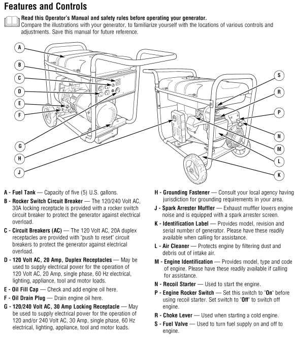
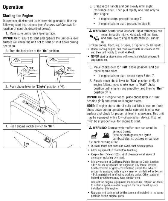
2 Briggs & Stratton Model: OPERATING INSTRUCTIONS EQUIPMENT: GPU TYPE: Gasoline MANUFACTURER: Briggs & Stratton Model: BEFORE STARTING Complete Daily Check before using. Check placards for special instructions and restrictions. Check location of levers, switches and controls. Check general condition of entire unit. Equipment Description The generator is an engine-driven, revolving field, alternating current (AC) generator. It was designed to supply electrical power for operating compatible electrical lighting, appliances, tools and motor loads. The generator's revolving field is driven at about 3,600 rpm by a single-cylinder engine.
3

4 120/240 Volt AC, 30 Amp, Locking Receptacle Use a NEMA L14-30 plug with this receptacle. Connect a 4-wire cord set rated for 250 Volt AC loads at 30 Amps (or greater). You can use the same4-wire cord if you plan to run a 120 Volt load. 120 Volt AC, 20 Amp, Duplex Receptacles The duplex receptacles are protected against overload by push-to-reset circuit breakers. Use each receptacle to operate 120 Volt AC, single-phase, 60 Hz electrical loads requiring up to 2,400 watts (2.4 kw) at 20 Amps of current. Use cord sets that are rated for 125 Volt AC loads at 20 Amps (or greater). Inspect cord sets before each use.
5
6

7 Davco Model: GP28R OPERATING INSTRUCTIONS EQUIPMENT: GPU TYPE: Electric MANUFACTURER: Davco Model: GP28R BEFORE STARTING Complete Daily Check before using. Check placards for special instructions and restrictions. Check location of levers, switches and controls. Check general condition of entire unit.

8 Foxtronics Model: PR-2000-T7S OPERATING INSTRUCTIONS EQUIPMENT: GPU TYPE: Electric MANUFACTURER: Foxtronics Model: PR-2000-T7S PURPOSE OF EQUIPMENT The Foxcart ground power unit is designed to provide smooth, high current DC power to aircraft during engine starts or ground maintenance. The Foxcart, when used as an external DC source, eliminates or minimizes excessive current drain from the aircraft s battery and battery relay contacts. It is also designed as a low profile unit that requires minimum ventilation and is easily moved in a crowded hangar by one person.

9 Front Panel
10 OPERATION 1. Move the Foxcart into position and set the wheel brakes. 2. Ensure that 14/28-volt selector switch is in the same voltage range as the Aircraft. (If cart is so equipped with this optional feature). 3. Plug the Foxcart Input Power Cable into the AC Outlet. 4. Switch the Foxcart ON/OFF breaker to ON and rotate the Step Switch to adjust the Voltmeter to the desired voltage. 5. Switch the Foxcart ON/OFF breaker to OFF and plug the DC cable into the Aircraft DC receptacle. 6. Switch the Foxcart ON/OFF breaker to ON and re-adjust the Step Switch to the desired voltage. Ideally, there will be no current draw until the aircraft system is activated. Some aircraft such as early Lear Jets have a direct connection between the external connection and the battery. An internal current draw of 100 Amperes may be observed on the ammeter of the FOXCART. This current will decrease as the batteries are charged. On this type of Aircraft, the batteries should be allowed to charge before energizing the Aircraft electrical system. 7. Perform normal start or maintenance. 8. After starting or completion of maintenance, switch the Foxcart ON/OFF breaker to OFF and disconnect the Power Cable from the Aircraft. Move the FOXCART to a safe distance and set the brake locks to prevent movement due to Jet or Prop blast. SOFTSTART OPERATION Softstart provided current limiting during engine starts to prevent over-torquing starter motors and starter drive mechanism during starts. Use this option only if your aircraft requires it. During a Softstart, the Foxcart produces about 20% or more of the current needed for a start and the Aircraft batteries supply the remaining current. If the Aircraft design maintains the ship s batteries on line, the FOXCART will supply all the power. After start, if the FOXCART is left on line long enough, it will recharge the Aircraft batteries.

11 GUINAULT MODEL: GA90V133 OPERATING INSTRUCTIONS EQUIPMENT: GPU TYPE: DIESEL MANUFACTURER: GUINAULT MODEL: GA90V133 GPU overview

12 CONTROL PANEL See next page for labeling
13 CONTROL PANEL INDICATORS FAULT DISPLAY (Mark 73) 400Hz frequency (Mark 22) FAULT pilot light (Mark 15) 400Hz current (Mark 21) EMERGENCY STOP (Mark 18) 400Hz voltage (Mark 20) 400Hz & 28V EF By-passed p. l. (33) ENGINE DATA DISPLAY (Mark 81) 400Hz ON/OFF (Mark 8 & 10) 400Hz ON pilot light (Mark 9) LOW FUEL LEVEL pilot light (Mark 3) HOURMETER (Mark 16) 28VDC voltage (Mark 23) (*) FUEL LEVEL indicator (Mark 2) 28VDC current (Mark 24) (*) pilot light (Mark 31) 28VDC ON/OFF (Mark 11 & 13) (*) OK pilot light (Mark 5) 28VDC ON pilot light (Mark 12) (*) 0 1 (Ignition) (Mark 1) IGNITION pilot light (Mark 4) AUTOM. GPU SHUTDOWN p. light (M. 72) START (Mark 17) SPEED commutator (Mark 74) (*) SPEED pilot light (Mark 58 or 75) (*) 28V I LIMITATION commutator (Mark 7) (*) Earth leakage protection inhibited pilot light (Mark 77) (*) Engine starting safety key (Mark 78) (*)
14 BEFORE STARTING Complete Daily Check before using. Check placards for special instructions and restrictions. Check location of levers, switches and controls. Check that the tow bar is in high position Check the good condition of the cables and the aircraft plugs. Check general condition of entire unit. Operating sequence Starting GPU 1. Unlocked the EMERGENCY STOP (Mark 18) NOTE : According to the equipment (OPTION) ; engage the key switch of the engine starting safety system. 2. Put the switch 0 1 (Ignition) (Mark 1) on 1 position a. A test of panel lamps is carried out for about 7 sec. b. Check that the two EF BYPASSED pilot lights (marks 33) are light off ( & EF commutator (mark 6 or 28) Maintenance control panel - on PLANE mode). c. Make sure that the SPEED pilot light (mark 58 or 75) is off (& SPEED SELECTION commutator (mark 59) Maintenance control panel - on AUTO mode) d. In case the EF BYPASSED pilot lights is ON. Don t use the GPU. WARNING EF LIGHT (MARK 33) ON, MEANS THE SAFETY DEVICE IS BYPASSED FOR MAINTENANCE PURPOSE. NOTE : According to the ambient temperature, an engine preheating cycle is automatically started. If the pilot light (Mark 31) is lit, the engine preheating is put into operation When the pilot light (Mark 31) switches off, the engine starting is possible In case where ambient temperature does not require a preheating cycle, the control light (Mark 31) switches off after the control lights test period and the engine starting is possible.
15 3. Launch the starter by pressing the START (Mark 17) If the engine starting is OK, the engine reaches is idle speed. A delay of about 1 minute prevents the use of the 400Hz and 28VDC generations. During this warming period, the OK pilot light (Mark 5) blinks, then becomes still. The HOURMETER (Mark 16) counts the time only while engine is running 4. Before operating the generations * For GPUs WITH aircraft plugs stored detection : when at least one plug is removed from its support : the SPEED pilot light (mark 58) flashes during 5sec., after the time, the speed increase up to the nominal speed, the SPEED pilot light switches off. * For GPUs WITHOUT aircraft plugs stored detection: Switch the SPEED commutator (mark 74) on NOMINAL SPEED position, the SPEED integrated pilot light (mark 75) flashes during 5sec., after the time, the speed increase up to the nominal speed, the SPEED pilot light switches off. the 400Hz voltmeter (Mark 20) indicates 115VAC, the 400Hz frequency meter (Mark 22) indicates 400Hz. REMARK : If the SPEED commutator (Mark 74 or 59) is in NOMINAL SPEED position when the GPU is started; the unit runs idle during the warming period, then the engine increases to its nominal rating. NOTE : The 400 Hz and 28 VDC generations can be used simultaneously up to power supplied by the engine. 5. The generations are available as soon as the OK pilot light (Mark 5) is still.
 of the selected 400 Hz circuit, the output contactor is on, the integrated 400Hz ON pilot light (Mark 9) lights up, the aircraft is supplied 4.")
16 Operating the 400Hz generation 1. Check that the 400Hz EF BYPASS pilot light (Mark 33) is switched off 2. Connect the cable to the aircraft 3. Energizing Press the green 400Hz ON (Mark 8) of the selected 400 Hz circuit, the output contactor is on, the integrated 400Hz ON pilot light (Mark 9) lights up, the aircraft is supplied 4. De-energizing Press the red 400Hz OFF (Mark 10) of the selected 400 Hz circuit, the output contactor opens, the integrated pilot light switches off, the cable is not energized anymore. 5. Disconnect cable from the aircraft
17 Operating the 28VDC generation (According to the equipment) 1. Place the 28V I LIMITATION commutator (Mark 7) on the required position. 0 : No current limitation 1 : Limitation to the pre-adjusted value (1275A) 2. Connect the cable to the aircraft 3. Energizing Press the green 28V ON (Mark 11), the output contactor is on, the integrated 28V ON pilot light (Mark 12) lights up, the aircraft is supplied 4. De-energizing Press the red 28V OFF (Mark 13), the output contactor opens, the integrated pilot light switches off, the cable is not energized anymore. 5. Disconnect cable from the aircraft

18 HOBART OPERATING INSTRUCTIONS EQUIPMENT: GPU MANUFACTURER: HOBART MODEL: JET EX-2, EX-3, EX-4, EX-4D TYPE: GASOLINE/DIESEL TRAILER MOUNT 28V DC MODEL: JET EX-2, JET EX-3 JET EX-4, JET EX-4D BEFORE STARTING Complete Daily Check before using. Check placards for special instructions and restrictions. Check location of levers, switches and controls. Check general condition of entire unit. Starting The Engine (Figure 1 above) 1. Check AIR CLEANER SERVICE INDICATOR lamp (17, Figure 1). If lamp is glowing, replace air filter element and/or remove other objects that obstruct air flow. 2. Place SPEED CONTROL toggle switch (11) in the IDLE (down) position. Caution: If the engine stalls or falters in starting, wait three or four seconds before re-engaging starter. This will prevent possible damage to starter or the engine. DO NOT Operate the starter for periods longer than 15 seconds at a time. An interval of at least two minutes should be allowed between cranking periods to protect the starter from overheating. 1. Hold engine ENGINE CIRCUIT toggle switch (14) in START position. 2. Press and hold ENGINE START push-button switch (13). Release as soon as engine starts. 3. Release engine ENGINE CIRCUIT toggle switch (14) to RUN position when oil pressure builds up. 4. Observe engine RPM on the TACHOMETER (2), and observe engine for excessive vibration. Idle speed should be 750 RPM + 50 RPM. If there is excessive vibration, adjust engine idle speed, gradually increasing or decreasing it - whichever is necessary - until vibration is reduced. 5. Allow engine to warm up before applying a load.
 Figure 1 11.")
19 1. CONTROL PANEL light DS401, DS TACHOMETER M HOUR METER M VOLTMETER (generator) M AMMETER M PANEL LIGHTS FUSE (10 amp) F PANEL LIGHTS toggle switch S CONTACTOR CONTROL toggle switch S CONTACTOR CLOSED lamp DS CURRENT LIMITING CONTROL potentiometer R402 Control Panel Assembly (Front View) Figure SPEED CONTROL toggle switch S ENGINE ON lamp DS ENGINE START push button switch S ENGINE CIRCUIT toggle switch S ENGINE CIRCUIT FUSE (20 Amp.) F WATER TEMPERATURE gauge M AIR FILTER RESTRICTION INDICATOR lamp DS OIL PRESSURE gauge M FUEL gauge M VOLTMETER (battery) M401
20 WARNING: The engine s entire exhaust system will get very hot and cause severe burns if touched. Generator Operation (Figure 1) 1. Place speed control switch (11) in RATED RPM (up) position. Engine speed will be 2140 RPM, and the generator will automatically build up to produce rated voltage. 2. Adjust CURRENT LIMITING CONTROL potentiometer (10) if necessary. Deliver Power 1. Connect output cable to AIRCRAFT. 2. Hold CONTACTOR CONTROL toggle switch (8) in CLOSE position. Release to ON position as soon as green CONTACTOR CLOSED lamp (9) comes on. Stop Operation (Shutdown) 1. Normal Conditions a. When power delivery is completed (aircraft discontinues drawing current), place CONTACTOR CONTROL toggle switch (8) in OFF position. The CONTACTOR CONTROL lamp (9) should go off to indicate load contactor has opened and power is no longer available at the aircraft. b. Place SPEED CONTROL toggle switch (11) in IDLE (down) position. Allow engine to run for 2 to 3 minutes. c. Disconnect output cable from aircraft receptacle and store cable in cable trays or on cable hangers as the case may be. d. Place ENGINE CIRCUIT toggle switch (14) in STOP position. CAUTION: THE BATTERY WILL DRAIN if the ENGINE CIRCUIT toggle switch (14), is not placed in STOP position after shutdown, Emergency Conditions 1. To prevent personal damage or damage to generator set, use of the EMERGENCY SHUT DOWN (E-STOP) push button switch (1, Figure 2) will provide immediate shut down of the engine. Once pushed in, the E-STOP button must be pulled back out to restart the generator set. Depress E-STOP button; engine will shut down Pull E-STOP button back out to restart.

21 HOBART OPERATING INSTRUCTIONS EQUIPMENT: 28V DC RECTIFIER MODEL: 6T28-400CL, 6T28-600CL TYPE: Electric MANUFACTURER: HOBART MODEL: 6T28-400CL 6T28-600CL ELECTRIC SHOCK AND FIRE CAN KILL! READ AND UNDERSTAND ALL OPERATING INSTRUCTIONS BEFORE ATTEMPING TO OPERATE THE EQUIPMENT. OPERATION ATTEMPTS BY UNTRAINED PERSONNEL CAN ENDANGER PEOPLE, THIS EQUIPMENT, AND THE LOAD. DO NOT ATTEMPT TO OPERATE THE EQUIPMENT FOR USES NOT APPROVED BY THE MANUFACTURE, OR AT INPUT AND OUTPUT RATINGS NOT LISTED IN THE SPECIFICATIONS CAUTION ALWAYS CHECK CORDS FOR CUTS, AND PULLED WIRES FROM SOURCE TO UNIT AND FROM UNIT TO AIRCRAFT. PREPARATION FOR OPERATION 1. Verify input power is disconnected (OFF) at source. 2. Verify that the supply input connections agree with the input voltage 3. Connect your output cable between your load and the proper connection points in the DC power supply. 4. When all covers or panels are in place, turn ON the source of input power. 5. Set R13 start level knob (9,Fig. 1) to the output surge limit required for your load.
22 OPERATION PROCEDURE 1. Input Control Functions a. Turn on S1 input contactor switch (3, Fig.1). b. Verify that only the amber input power light (7, Fig.1) glows. If the light glows, no problem exists. 2. Output Control Functions a. Hold the S2 output contactor switch (4, Fig.1) in the up CLOSE position long enough for the green output contactor light (10, Fig. 1) to glow. b. Release the S2 switch to the middle ON position. c. Verify that M1 DC ammeter (5, Fig.1) does not read an excessive amperage. Release S2 switch. d. The DC power supply should continue to deliver power until the S2 switch is placed in the down OFF position. 3. VOLTMETER a. Verify on the M2 DC voltmeter (6, Fig1) that the DC output Voltage level is correct. If not, turn off power supply, disconnect your load, and refer to Maint. Service. 4. OUTPUT CURRENT LIMIT a. If the DC ammeter continuously reads more then 400/600 A DC. After start up, immediately turn R13 current control (9, Fig.1) down to continuous operation current point, normally 400/600 A DC. This may prevent automatic overload trip or blowing of fuses at the source. b. If R13 has no affect or if the output current cannot be decreased. About 250 A DC at the R13 minimum position, a faulty SCR device or control circuit malfunction is indicated requiring power supply repair. Contact Maint. Service.

23 HOBART OPERATING INSTRUCTIONS EQUIPMENT: GPU MODEL: 60G20-F / 60G20-K / 60GP20 TYPE: Diesel MANUFACTURER: HOBART MODEL: 60G20-F / 60G20-K / 60GP20 BEFORE STARTING Complete Daily Check before using. Check placards for special instructions and restrictions. Check location of levers, switches and controls. Check general condition of entire unit. DAILY CHECK These items should be checked daily: Fuel supply. Oil level. Radiator coolant level. Battery water level. Tire inflation and condition (if trailer mounted). General condition of entire unit including lights, instruments canopy enclosure, etc. Starting Engine, Normal 1. If illumination is required, place light switch in ON position. Note: This switch must be ON to check fuel quantity when engine is stopped. 2. Make sure engine STOP control is at IN position. 3. Be sure engine air shut-off value is in LATCHED, open position. Push lever DOWN to LATCH value OPEN. 4. Place engine-generator control switch in IDLE position.
24 CAUTION: IF ENGINE FAILS TO START WITHIN 30 SECONDS, RELEASE THE START SWITCH AND ALLOW THE STARTING MOTOR TO COOL FOR A FEW MINUTES. IF THE ENGINE FAILS TO START AFTER FOUR (4) ATTEMPTS, TROUBLESHOOT TO DETERMINE THE CAUSE. 5. Activate engine START switch to crank engine. Release the START switch as soon as the engine starts. When engine starts, observe engine protective system light. When this light glows GREEN, it indicates the fuel pressure switch is closed and the engine protective system is functional. Note: If the air shut-off value is tripped for any reason during start-up, it will be necessary to latch the value mechanism by pushing the latch lever down. If the shut down value cannot be latched, check the overspeed governor. It may have been tripped by an overspeed condition. Press the RESET button on overspeed governor head, then latch shutdown value open. Always reset the overspeed governor immediately after an overspeed trip, because the shut down solenoid will remain energized and discharge the batteries until governor is reset. CAUTION: MAKE CERTAIN THERE IS SUFFICIENT FUEL. DO NOT ALLOW UNIT TO RUN OUT OF FUEL. IT WILL REQUIRE ALL AIR TO BE BLED FROM FUEL SYSTEM BEFORE ENGINE WILL RESTART. 6. Observe all engine instruments for normal operation. CAUTION: DO NOT ALLOW ENGINE TO IDLE FOR LONG PERIODS OF TIME. 7. Allow engine to idle and warm for about five minutes before applying load.
25 Engine Starting, Cold Weather Note: A cold weather starting aid kit is provided to assist in starting the engine at temperatures below 50. If engine fails to start normally because of cold temperature, use the starting aid as follows: CAUTION: USE STARTING AID FOR STARTING. DO NOT OPERATE WHILE ENGINE IS RUNNING. DO NOT FLOOD ENGINE WITH STARTING FLUID. A SERIOUS EXPLOSION COULD RESULT. 1. Cold weather starting procedures are exactly the same as for normal starting except: a. Before cranking the engine, pull the starting aid control OUT to full extent of travel. Hold for 2 to 3 seconds (this allows the starting aid value chamber to fill with pressurized ether). b. Push the control IN (this step sprays starting fluid into engine intake manifold). c. Press engine STARTER switch to crank engine. Power Delivery 1. Connect cable plug to the aircraft receptacle. Be sure connectors are fully and securely mated. 2. For normal operation, TEST BANK switch will be OFF and the AUTOMATIC/MANUAL switch will be in the AUTOMATIC position. Note: These switches are located inside power unit and are normally only used for test. 3. Place the engine generator control switch in BUILD-UP VOLTAGE position momentarily; then allow it to position itself in GEN position. The electronic governor will immediately increase engine speed to 2,000 RPM and maintain it. 4. When satisfactory frequency and voltage values are indicated by the instruments, close the load contactor by momentarily placing the load contactor switch in the top (spring loaded) ON position. 5. The GREEN indicating light should glow at once to indicate the load contactor is closed and power is available at the aircraft. 6. As soon as the light glows, release the switch to the center ON position.
26 Discontinue Power Delivery 1. Place the load contactor switch in OFF position. GREEN light should go OFF immediately to indicate the load contactor has opened and power is no longer being delivered to the aircraft. 2. Place the engine generator control in IDLE position. NEVER DISCONNECT THE OUTPUT CABLE WHILE POWER IS BEING DELIVERED TO AIRCRAFT. 3. Disconnect output cable from aircraft receptacle and store cable. Engine Shut Down 1. Allow the engine to idle a few minutes before stopping to permit cooling. 2. Pull the STOP control OUT and hold until the engine stops. This control is spring loaded and should return to the IN position when released. 3. Place light switch in OFF position, if used.

27 HOBART MODEL: 60G20-S / 90G20 OPERATING INSTRUCTIONS EQUIPMENT: GPU TYPE: Diesel MANUFACTURER: HOBART MODEL: 60G20-S / 90G20 BEFORE STARTING Complete Daily Check before using. Check placards for special instructions and restrictions. Check location of levers, switches and controls. Check general condition of entire unit. Starting Engine, Normal 1. Set handbrake. 2. Place gear lever in NEUTRAL position. 3. Place operating mode switch in DRIVE position. 4. Be sure contactor switch is in OFF position. 5. Make sure engine STOP control is all the way IN. 6. Depress accelerator slightly.
28 CAUTION: IF ENGINE FAILS TO START WITHIN 30 SECONDS, RELEASE THE START SWITCH AND ALLOW THE STARTING MOTOR TO COOL FOR A FEW MINUTES. IF THE ENGINE FAILS TO START AFTER FOUR (4) ATTEMPTS, TROUBLESHOOT TO DETERMINE THE CAUSE. 7. Press and hold STARTER switch to crank engine. Note: If the air shut-off value is unlatched, the starter will not function. Re-latch shut down value to the OPEN position (value is located on intake manifold). CAUTION: MAKE CERTAIN THERE IS SUFFICIENT FUEL. DO NOT ALLOW UNIT TO RUN OUT OF FUEL. IT WILL REQUIRE ALL AIR TO BE BLED FROM FUEL SYSTEM BEFORE ENGINE WILL RESTART. 8. Observe all engine instruments for normal operation. CAUTION: DO NOT ALLOW ENGINE TO IDLE FOR LONG PERIODS OF TIME. 9. Allow engine to idle and warm for about five minutes before applying load. Engine Starting, Cold Weather Note: A cold weather starting aid kit is provided to assist in starting the engine at temperatures below 50. If engine fails to start normally because of cold temperature, use the starting aid as follows: CAUTION: USE STARTING AID FOR STARTING. DO NOT OPERATE WHILE ENGINE IS RUNNING. DO NOT FLOOD ENGINE WITH STARTING FLUID. A SERIOUS EXPLOSION COULD RESULT. 1. Cold weather starting procedures are exactly the same as for normal starting except: a. Before cranking the engine, pull the starting aid control OUT to full extent of travel. Hold for 2 to 3 seconds (this allows the starting aid value chamber to fill with pressurized ether). b. Push the control IN (this step sprays starting fluid into engine intake manifold). c. Press engine STARTER switch to crank engine.
29 Mobile Operation ALWAYS CHECK THE OPERATION OF THE SERVICE BRAKES BEFORE MOVING VEHICLE. 1. Make sure the operating mode switch is in the DRIVE position. 1. Depress clutch. 2. Move gear shift lever to first speed position. 3. Release handbrake. 4. Release clutch pedal and depress accelerator. CAUTION: DO NOT USE THIRD SPEED ON RAMP. DO NOT USE UNIT TO PUSH OR PULL OTHER EQUIPMENT. 5. Accelerate and change gears as required. 6. Stopping of vehicle: NOTE: Because of the great force of inertia built in the generator rotor, engine compression has no braking effect when the accelerator is released. a. Always depress clutch pedal before applying brakes. Thus, the brakes do not need to slow the rapidly turning rotor in addition to stopping the vehicle. a. Apply brakes smoothly and avoid sudden stops except in the case of an emergency. b. If vehicle is to be parked, place the gearshift lever in the NEUTRAL position and apply brakes. c. To stop engine, pull STOP control and hold until engine stops rotating. Power Delivery 1. With engine running at idle speed, place operating mode control switch in GEN position. Electronic governor will take control of engine speed (2,000 RPM). 2. Observe generator instruments. Frequency meter should indicate Hz. Voltmeter should indicate 115 VAC when line switch is in LINE-TO-NEUTRAL position. 3. Connect power cable to aircraft. Be sure connectors are fully and securely mated. 4. Momentarily place the contactor control switch in TOP (spring-loaded) ON position. GREEN indicating light should glow at once to indicate the load contactor is closed and power is available at the aircraft. As soon as the light glows, release the switch. It will automatically return to the center ON position. 5. Check the voltage and current in each of the three phases early in the power delivery run.
30 NOTE: A condition of over voltage, under voltage, under frequency, over frequency or overload in the output will automatically open the load contactor and turn on the applicable indicating light to signal the operator which of the above faults caused the protective monitor system to operate. After the fault has been corrected, press the RESET switch to turn off the indicating light and reset the protective relay system. Proceed with power delivery by operating the load contactor switch. Discontinue Power Delivery 1. Place the load contactor switch to the OFF position. GREEN light should go OFF immediately indicating the load contactor has opened. NEVER DISCONNECT THE OUTPUT CABLE WHILE POWER IS BEING DELIVERED TO AIRCRAFT. 2. Disconnect output cable at aircraft. Stow cable and place plug connector in plug box. 3. Place operating mode switch in DRIVE position to allow engine to idle. NOTE: If the engine is stopped without first placing mode switch in DRIVE position, an under frequency fault may be indicated at the next start-up. 4. Allow the engine to idle a few minutes, before stopping after a heavy power delivery run, to permit cooling. 5. To stop the engine, pull STOP control and hold until engine stops rotating.

31 HOBART MODEL: 90P20P / 60P20P OPERATING INSTRUCTIONS EQUIPMENT: GPU TYPE: Diesel MANUFACTURER: HOBART MODEL: 90P20P / 60P20P BEFORE STARTING Complete Daily Check before using. Check placards for special instructions and restrictions. Check location of levers, switches and controls. Check general condition of entire unit. DAILY CHECK These items should be checked daily: Fuel supply. Oil level. Radiator coolant level. Battery water level. Tire inflation and condition (if trailer mounted). General condition of entire unit including lights, instruments canopy enclosure, etc.
32 Starting Engine, Normal 1. If illumination is required, place light switch in ON position. Note: This switch must be ON to check fuel quantity when engine is stopped. 2. Make sure engine STOP control is at IN position. 3. Place engine-generator control switch in IDLE position. CAUTION: IF ENGINE FAILS TO START WITHIN 30 SECONDS, RELEASE THE START SWITCH AND ALLOW THE STARTING MOTOR TO COOL FOR A FEW MINUTES. IF THE ENGINE FAILS TO START AFTER FOUR (4) ATTEMPTS, TROUBLESHOOT TO DETERMINE THE CAUSE. 4. Activate engine START switch to crank engine. Release the START switch as soon as the engine starts. When engine starts, observe engine protective system light. When this light glows GREEN, it indicates the fuel pressure switch is closed and the engine protective system is functional. CAUTION: MAKE CERTAIN THERE IS SUFFICIENT FUEL. DO NOT ALLOW UNIT TO RUN OUT OF FUEL. IT WILL REQUIRE ALL AIR TO BE BLED FROM FUEL SYSTEM BEFORE ENGINE WILL RESTART. 5. Observe all engine instruments for normal operation. CAUTION: DO NOT ALLOW ENGINE TO IDLE FOR LONG PERIODS OF TIME. 6. Allow engine to idle and warm for about five minutes before applying load.
33 Engine Starting, Cold Weather Note: A cold weather starting aid kit is provided to assist in starting the engine at temperatures below 50. If engine fails to start normally because of cold temperature, use the starting aid as follows: CAUTION: USE STARTING AID FOR STARTING. DO NOT OPERATE WHILE ENGINE IS RUNNING. Warning: DO NOT FLOOD ENGINE WITH STARTING FLUID. A SERIOUS EXPLOSION COULD RESULT. 1. Cold weather starting procedures are exactly the same as for normal starting except: a. Before cranking the engine, pull the starting aid control OUT to full extent of travel. Hold for 2 to 3 seconds (this allows the starting aid value chamber to fill with pressurized ether). b. Push the control IN (this step sprays starting fluid into engine intake manifold). c. Press engine STARTER switch to crank engine. Power Delivery 1. Connect cable plug to the aircraft receptacle. Be sure connectors are fully and securely mated. 2. For normal operation, TEST BANK switch will be OFF and the AUTOMATIC/MANUAL switch will be in the AUTOMATIC position. Note: These switches are located inside power unit and are normally only used for test. 3. Place the engine generator control switch in BUILD-UP VOLTAGE position momentarily; then allow it to position itself in GEN position. The electronic governor will immediately increase engine speed to 2,000 RPM and maintain it. 4. Observe generator instruments. Frequency meter should indicate Hz and voltmeter should indicate 115 volts in all three phases, A, B and C. 5. When satisfactory frequency and voltage values are indicated by the instruments, close the load contactor by momentarily placing the LOAD CONTACTOR switch in the top (spring loaded) position. The GREEN indicating light should glow at once to indicate that the load contactor is closed and power is available at the aircraft. As soon as the light glows, release the switch to the center ON position.
34 Discontinue Power Delivery 1. Place the load contactor switch in OFF position. GREEN light should go OFF immediately to indicate the load contactor has opened and power is no longer being delivered to the aircraft. 2. Place the engine generator control in IDLE position. Warning: NEVER DISCONNECT THE OUTPUT CABLE WHILE POWER IS BEING DELIVERED TO AIRCRAFT. 3. Disconnect output cable from aircraft receptacle and store cable. Engine Shut Down 1. Allow the engine to idle a few minutes before stopping to permit cooling. 2. Pull the STOP control OUT and hold until the engine stops. This control is spring loaded and should return to the IN position when released. 3. Place light switch in OFF position, if used.

35 HOBART OPERATING INSTRUCTIONS EQUIPMENT: GPU MODEL: 60P20EV TYPE: Diesel MANUFACTURER: HOBART MODEL: 60P20EV BEFORE STARTING Complete Daily Check before using. Check placards for special instructions and restrictions. Check location of levers, switches and controls. Check general condition of entire unit. DAILY CHECK These items should be checked daily: Fuel supply. Oil level. Radiator coolant level. Battery water level. Tire inflation and condition (if trailer mounted). General condition of entire unit including lights, instruments canopy enclosure, etc.
36 Starting Engine, Normal 1. If illumination is required, place light switch in ON position. Note: This switch must be ON to check fuel quantity when engine is stopped. 2. Make sure engine STOP control is at IN position. 3. Place engine-generator control switch in IDLE position. CAUTION: IF ENGINE FAILS TO START WITHIN 30 SECONDS, RELEASE THE START SWITCH AND ALLOW THE STARTING MOTOR TO COOL FOR A FEW MINUTES. IF THE ENGINE FAILS TO START AFTER FOUR (4) ATTEMPTS, TROUBLESHOOT TO DETERMINE THE CAUSE. 4. Activate engine START switch to crank engine. Release the START switch as soon as the engine starts. When engine starts, observe engine protective system light. When this light glows GREEN, it indicates the fuel pressure switch is closed and the engine protective system is functional. CAUTION: MAKE CERTAIN THERE IS SUFFICIENT FUEL. DO NOT ALLOW UNIT TO RUN OUT OF FUEL. IT WILL REQUIRE ALL AIR TO BE BLED FROM FUEL SYSTEM BEFORE ENGINE WILL RESTART. 5. Observe all engine instruments for normal operation. CAUTION: DO NOT ALLOW ENGINE TO IDLE FOR LONG PERIODS OF TIME. 6. Allow engine to idle and warm for about five minutes before applying load.
37 Power Delivery 1. Connect cable plug to the aircraft receptacle. Be sure connectors are fully and securely mated. 2. For normal operation, TEST BANK switch will be OFF and the AUTOMATIC/MANUAL switch will be in the AUTOMATIC position. Note: These switches are located inside power unit and are normally only used for test. 3. Place the engine generator control switch in BUILD-UP VOLTAGE position momentarily; then allow it to position itself in GEN position. The electronic governor will immediately increase engine speed to 2,000 RPM and maintain it. 4. Observe generator instruments. Frequency meter should indicate Hz and voltmeter should indicate 115 volts in all three phases, A, B and C. 5. When satisfactory frequency and voltage values are indicated by the instruments, close the load contactor by momentarily placing the LOAD CONTACTOR switch in the top (spring loaded) position. The GREEN indicating light should glow at once to indicate that the load contactor is closed and power is available at the aircraft. As soon as the light glows, release the switch to the center ON position.
38 Discontinue Power Delivery 1. Place the load contactor switch in OFF position. GREEN light should go OFF immediately to indicate the load contactor has opened and power is no longer being delivered to the aircraft. 2. Place the engine generator control in IDLE position. Warning: NEVER DISCONNECT THE OUTPUT CABLE WHILE POWER IS BEING DELIVERED TO AIRCRAFT. 3. Disconnect output cable from aircraft receptacle and store cable. Engine Shut Down 1. Allow the engine to idle a few minutes before stopping to permit cooling. 2. Pull the STOP control OUT and hold until the engine stops. This control is spring loaded and should return to the IN position when released. 3. Place light switch in OFF position, if used.

39 JETWAY SYSTEMS OPERATING INSTRUCTIONS EQUIPMENT: GPU MANUFACTURER: JETWAY SYSTEMS MODEL: Jetpower I and II TYPE: Solid State MODEL: Jetpower I and II WARNING: CONTAINS HIGH VOLTAGE. DISCONNECT POWER BEFORE OPENING ACCESS PANELS. REMOVE ALL RINGS, WATCHES, ETC.,BEFORE ACCOMPLISHING POWER ON TROUBLESHOOTING. 400 HZ GROUND POWER UNIT CONTROL PANEL STATUS LIGHTS STATUS LIGHTS Fault Unit Shut Down RED Check alarm board per 1-4, Paragraph 2, JETPOWER 400Hz Specifications. INPUT PHASE INCORRECT Red Flashing Shut unit off correct input phase. 28V PRESENT FROM AIRCRAFT Green This light indicates power is present at the aircraft plug. 28V NOT PRESENT FROM AIRCRAFT Green Flashing The problem is in the aircraft INPUT POWER PRESENT Orange Unit is ready to be turned on. 28V AIRCRAFT BYPASS ON Orange Flashing Do not connect to aircraft without turning off the 28V aircraft bypass switch.
40 Start Up Procedures 1. Powering Aircraft a. Apply 480 VAC, 60 Hz, 3 Phase input power to the JETPOWER Unit though the appropriate disconnected switch. The red and orange light will come on simultaneously. The red light will go out in approximately four (4) seconds if no faults exist within the unit. The orange light will remain on in a steady state condition if the input phase is in the correct ABC phase rotation. b. Connect the 400 Hz aircraft plug to the aircraft. c. Activate POWER ON (start) pushbutton on the JETPOWER control box. correct results are indicated by a steady green light on the side panel of the unit. NOTE: The STOP pushbutton may need to be activated to reset the unit prior to activating the POWER ON pushbutton. 2. Powering the JETPOWER Unit without an Aircraft Follow the same procedure as above except the 28 VDC bypass switch must be In the ON position before the POWER ON pushbutton can be activated. 3. Adjustment If adjustment of the output voltage is desired, lower the primary access panel to gain access to a trim potentiometer adjustment knob. A meter is located next to the knob. 4. Shut Off Procedures a. To remove power from the inverter, depress the STOP pushbutton on the JETPOWER control box. The result is indicated by the loss of the green light. b. Carefully remove the aircraft power cable(s) and replace on hanger hooks.

41 Stewart & Stevenson MODEL: TM-4900D OPERATING INSTRUCTIONS EQUIPMENT: GPU TYPE: DIESEL MANUFACTURER: Stewart & Stevenson MODEL: TM-4900D BEFORE STARTING Complete Daily Check before using. Check placards for special instructions and restrictions. Check location of levers, switches and controls. Check electrical cord and connection for wear and breakage Check general condition of entire unit. Starting Engine (Normal) 1. Set hand brake. 2. Assure protective system warning lights are OFF. 3. Place engine RUN/STOP switch to the RUN position. 4. Press the engine START button; release when engine starts. The engine will attain idle speed when the manually activated throttle handle is fully depressed. NOTE: Do not keep starter engaged for more than 30 seconds at a time. This vehicle is equipped with a cold start kit. In extreme cold, it may be necessary to inject ether into the engine by pulling the ether aid cable handle. To use, rotate engine with starter; then pull cable handle. NEVER INJECT ETHER INTO THE ENGINE UNLESS IT IS ROTATING. 5. Allow engine to warm up. 6. Pull the throttle control T handle OUT to maximum load speed position and lock.
42 Power Delivery 1. Observe AC voltmeter for buildup of generator voltage. If no voltage has built up, momentarily actuate FIELD FLASH switch. 2. Observe the frequency meter for an indication of Hertz. Engine speed and generator frequency can be precisely adjusted with the throttle control. 3. Place CABLE INTERLOCK switch in NORMAL position. 4. Make sure load contactor is open. (LOAD CONTACTOR CLOSED lamp should be dark). 5. Plug AC load cable into aircraft. 6. To apply 115/200 VAC to the aircraft, momentarily press the CONTACTOR CLOSE button. The LOAD CONTACTOR CLOSED lamp should illuminate. Discontinue Power Delivery 1. Momentarily press the CONTACTOR OPEN button. The LOAD CONTACTOR CLOSED lamp should extinguish. 2. If the CABLE INTERLOCK switch is in the NORMAL position, leave it there. If it is not, operate it to NORMAL. 3. Unplug the load cable from the aircraft and store properly. 4. Operate throttle control to idle position. 5. Allow diesel engine to idle approximately 5 minutes. 6. Operate ENGINE/RUN STOP switch to STOP position. DAILY CHECK The following items are to be checked daily. 1. Fuel Supply 2. Tire inflation and condition

43 Stewart & Stevenson MODEL: DAVCO OPERATING INSTRUCTIONS EQUIPMENT: GPU TYPE: DIESEL MANUFACTURER: Stewart & Stevenson MODEL: DAVCO BEFORE STARTING Complete Daily Check before using. Check placards for special instructions and restrictions. Check location of levers, switches and controls. Check general condition of entire unit. OPERATING PROCEDURES WARNING: DO NOT CONNECT LIVE POWER CABLE(S) TO AIRCRAFT. SEVERE ELECTRICAL ARCING MAY CAUSE SERIOUS INJURY, DEATH AND/OR DAMAGE TO EQUIPMENT. 1. Set engine toggle switch to ON. The engine control unit will automatically control the starting function and cycle engine start. 2. Observe panel gauges for operation. 3. Observe voltmeter reading for 115 VAC. 4. Observe frequency reading for 400 Hz.
44 GENERATOR OPERATION ( AC POWER ): WARNING: DO NOT CONNECT ENERGIZED POWER CABLE TO AIRCRAFT. COULD CAUSE SERIOUS INJURY. 1. Connect AC cable to aircraft. 2. Check voltmeter 3. Press AC LOAD ON push-button to provide AC power to the aircraft. a. AC fault indicators: If the AC output reaches the protective limits the AC FAULT indicators will light, and the output contactor will open to remove power from output cable. b. Reset Fault by shutting down and restarting. SHUT-DOWN PROCEDURES: 1. Press AC LOAD CABLE OFF push-button. 2. Disconnect cable from aircraft. 3. Allow unit to cool down for (3) minutes, then set IGNITION switch to OFF.

45 TLD Model: GPU 4090 OPERATING INSTRUCTIONS EQUIPMENT: GPU TYPE: Electric MANUFACTURER: TLD Model: GPU 4090 BEFORE STARTING Complete Daily Check before using. Check placards for special instructions and restrictions. Check location of levers, switches and controls. Check general condition of entire unit. DAILY CHECK These items should be checked daily: Fuel supply. Oil level. Radiator coolant level. Battery water level. Tire inflation and condition (if trailer mounted). General condition of entire unit including lights, instruments canopy enclosure, etc.
46 Delivering Power to the Aircraft 1. Connect the power cable to the AC external power receptacle on the aircraft. 2. Hold the contactor switch (#1 or #2 output) in the "CLOSE" position. 3. When the output lamp (#1 or #2) lights, release the contactor switch. 4. External power is now being supplied to the aircraft. Removing Power from the Aircraft 1. Place the contactor switch in the "OFF" position. 2. Disconnect the power cable from the aircraft. 3. Stow the power cable on the generator in the proper location. Shutting Down the Engine 1. Turn the ignition switch to OFF position. The engine will ramp down to idle and remain in idle for approximately one (1) minute to cool down. It will then shut down automatically. CAUTION: FAILURE TO ALLOW THE ENGINE TO IDLE AFTER OPERATING UNDER LOAD MAY LEAD TO TURBOCHARGER BEARING DAMAGE. DO NOT USE THE EMERGENCY STOP SWITCH TO SHUT DOWN THE UNIT DURING NORMAL OPERATION.


47 TRILECTRON Model: LP OPERATING INSTRUCTIONS EQUIPMENT: GPU TYPE: Electric MANUFACTURER: TRILECTRON Operation Model: LP28-400
48
49

50 TRILECTRON Model: 9OT4OOS OPERATING INSTRUCTIONS EQUIPMENT: GPU TYPE: Electric MANUFACTURER: TRILECTRON Model: 9OT4OOS BEFORE STARTING Complete Daily Check before using. Check placards for special instructions and restrictions. Check location of levers, switches and controls. Check general condition of entire unit. DAILY CHECK These items should be checked daily: Fuel supply. Oil level. Radiator coolant level. Battery water level. Tire inflation and condition (if trailer mounted). General condition of entire unit including lights, instruments canopy enclosure, etc. Operating Procedures Follow steps on control panel

51 Figure 1 Operating Procedures Engine Start 1. Set run/idle switch to idle position. 2. Set engine ignition switch to on position. 3. Press engine start push button switch1-2 seconds until engine starts. 4. Allow engine to idle 2-3 minutes to warm properly. 5. Set idle/run switch to run position for operating speed. Warning Never connect or disconnect output cable while power is being delivered. AC Output 1. Voltage and Frequency levels are factory set to 115 vac. 400 mz. 2. Connect AC power cable to aircraft. 3. Press AC load ON pushbutton. AC power is now supplied to aircraft. AC OFF 1. Press AC Load OFF push button to turn off AC power. The load indicator will go out. To Stop Engine 1. Set idle/run switch to idle. Engine will return to idle speed. 2. Disconnect cable from aircraft. Let engine run at idle speed for 2-3 minutes to cool, then set ignition switch to OFF.

52
53 Instrument Panel The GPU s instrument panel is located at the extreme rear of the unit. It provides the operator with controls and displays for generator and engine functioning.
54 Operating Procedures Engine Starting Procedures The engine and generator operating controls and monitoring equipment are mounted on the instrument panel. (Figure 14) 1. Turn the ignition switch to the "START" position. 2. Release the ignition switch when the engine starts. 3. The engine is now running at idle speed. Let the engine warm up to the operating temperature. 4. The engine is now running at idle speed. Let the engine warm up to the operating temperature. 5. Hold the engine switch in the "UP" position momentarily to bring the engine to operating speed and to build up generator voltage. Starting Engine in Cold Weather 1. This engine is equipped with an automatic intake manifold heater. Pre-heating to the heater takes place automatically when the engine ambient temperature reaches a predetermined value. 2. The heater light illustrates when pre-heating is taking place. Wait until the heater light goes out then follow the normal starting procedure. NOTE: Always wait until the heater light goes out then start the engine to ensure a successful and clean start.

55 TRIECTRON MODEL: 2000A (800A) OPERATING INSTRUCTIONS EQUIPMENT: GPU TYPE: DIESEL MANUFACTURER: TRIECTRON MODEL: 2000A (800A) BEFORE STARTING Complete Daily Check before using. Check placards for special instructions and restrictions. Check location of levers, switches and controls. Check general condition of entire unit. ENGINE STARTING PROCEDURES DO NOT CONNECT AN ENERGIZED POWER CABLE TO AIRCRAFT. MAY CAUSE SERIOUS INJURY, OR DAMAGE TO EQUIPMENT. 1. Set IGNITION switch to ON. FAULT MODE LOW OIL indicator will be illuminated. 2. Set RUN/IDLE switch to IDLE. 3. Press START push-button for 1-2 seconds to start engine. 4. Let engine idle for 2-3 minutes to warm up engine. DO NOT PLACE THE OUTPUT ON/OFF TO ON, OR MAKE ANY FURTHER SWITCH ADJUSTMENTS UNTIL THE UNIT IS PROPERLY CONNECTED TO THE AIRCRAFT. FAILURE TO COMPLY COULD RESULT IN EQUIPMENT DAMAGE, AND/OR INJURY TO PERSONEL.
56 GENERATOR OPERATING PROCEDURES 1. Connect power cord to aircraft. 2. Bring engine to operating speed by placing the RUN/IDLE switch To RUN position. 3. Set OUTPUT switch to ON to provide DC power to the power cable. DC OUTPUT ON indicator should be illuminated and volt meter be reading 28VDC. NEVER CONNECT OR DISCONNECT OUTPUT CABLE WHILE DC POWER IS BEING DELIVERED. SHUT DOWN PROCEDURES 1. Set OUTPUT ON/OFF switch to OFF. 2. Set engine RUN/IDLE switch to IDLE. 3. Disconnect DC power cable from aircraft. 4. Allow engine to run at idle for 2-3 minutes to cool down. 5. Set engine idle switch to OFF.
SECTION 3.00 WARNING WARNING ENGINE STARTUP AND SHUTDOWN PRESTART INSPECTION
 SECTION 3.00 ENGINE STARTUP AND SHUTDOWN PRESTART INSPECTION Be sure that the clutch, circuit breaker, or other main power transmission device is disconnected. Generators develop voltage as soon as the
Commander 15i Container and Pallet Loader. Property of American Airlines
 Commander 15i Container and Pallet Loader Section 2. Operation BEFORE ATTEMPTING TO OPERATE OR MAINTAIN THE VEHICLE, COMPLETELY READ AND UNDERSTAND THE OPERATION AND MAINTENANCE MANUAL, INCLUDING ALL DANGER,,
DASSAULT AVIATION Proprietary Data
 F2000EX EASY 02-49-00 CODDE 1 PAGE 1 / 2 TABLE OF CONTENTS 02-49 02-49-00 TABLE OF CONTENTS 02-49-05 GENERAL Introduction Sources Equipment location 02-49-10 DESCRIPTION Introduction Description Operating
User s Manual. Automatic Switch-Mode Battery Charger
 User s Manual Automatic Switch-Mode Battery Charger IMPORTANT Read, understand, and follow these safety rules and operating instructions before using this battery charger. Only authorized and trained service
Operation and Maintenance Manual
 OM-2075 430577-31 011596 Operation and Maintenance Manual Model 90C24 Generator Set Part No. 500046 Hobart Brothers Company Airport Systems Group Ground Power Equipment Troy, OH 45373 U.S.A. This page
CAUTION. Start & Stop Procedures. Section 1-2. Engine Oil Level
 Section 1-2 Start & Stop Procedures Before operating this machine, the operator must have: received operator training, a familiarity with this manual, and a complete understanding of all the procedures
CAUTION. Start & Stop Procedures. Section 4-2. Engine Oil Level
 Section 4-2 Start & Stop Procedures Before operating this machine, the operator must have: received operator training, a familiarity with this manual, and a complete understanding of all the procedures
ATA 49 AUXILIARY POWER UNIT
 F900EX EASY 02-49-00 CODDE 1 PAGE 1 / 2 TABLE OF CONTENTS 02-49 02-49-00 TABLE OF CONTENTS 02-49-05 GENERAL Introduction Sources APU location 02-49-10 DESCRIPTION Introduction Description Operating principle
INOVA HIGHTECH Ltd. MEP 002/003 Auto Starter Manual
 INOVA HIGHTECH Ltd. MEP 002/003 Auto Starter Manual Complete Installation and Operating Manual for the MEP 002/003 Auto / Remote Starter for the following MEP Power Generators: MEP 002A/003A/011A/802A/803A/811A
QUICK REFERENCE FOR DEPARTURE (updated 05/22/08)
") Mariah QUICK REFERENCE FOR DEPARTURE (updated 05/22/08) The Quick Reference for Departure is just that condensed checklists and reminders. It assumes that the charter guest/operator is experienced and
Mariah QUICK REFERENCE FOR DEPARTURE (updated 05/22/08) The Quick Reference for Departure is just that condensed checklists and reminders. It assumes that the charter guest/operator is experienced and
N1387 Series Troubleshooting Guide for N Alternators
 N1387 Series Troubleshooting Guide for N1387-1 Alternators Hazard Definitions These terms are used to bring attention to presence of hazards of various risk levels or to important information concerning
Troubleshooting Guide
 Troubleshooting Guide P/N 0153180 July 1999 P.O. Box 1160 St. Joseph, MO 64502-1160 1-800-255-0317 Fax: 816-360-9379 www.snorkelusa.com GENERAL INFORMATION This manual contains procedures for locating
Portable Lighting Equipment Operating Instructions Table of Contents
 Portable Lighting Equipment Operating Instructions Table of Generac Magnum Ingersoll Rand TEREX AMIDA TEREX GENIE Model: MLT3060 Model: LIGHTSOURCE Model: Amida AL4000 series Model: TML4000N Generac Magnum
60 Series Engine Controls
 ECU 60 Series Engine Controls Use CAUTION since you are applying 120VAC RMS to the AC Input terminals and that it is always potentially their during engine run!!! ECU is a registered trademark of Engineering
Dash8-200/300 - Auxiliary Power Unit APU CONTROLS AND INDICATORS. Page 1
 APU CONTROLS AND INDICATORS Page 1 APU control and indicators Page 2 closed APU controls and indicators Page 3 SYSTEM DESCRIPTION General The auxiliary power unit (APU) is a gas turbine engine, located
MODEL 520 REMOTE START ENGINE MANAGEMENT SYSTEM
 MODEL 520 REMOTE START ENGINE MANAGEMENT SYSTEM DSE 520 ISSUE 4 4/4/02 MR 1 TABLE OF CONTENTS Section Page INTRODUCTION... 4 CLARIFICATION OF NOTATION USED WITHIN THIS PUBLICATION.... 4 1. OPERATION...
TECHNICAL MANUAL OPERATOR S, UNIT, INTERMEDIATE (DS) AND INTERMEDIATE (GS) MAINTENANCE MANUAL FOR
 AND INTERMEDIATE (GS) MAINTENANCE MANUAL FOR") TM 5-2815-232-14 TECHNICAL MANUAL OPERATOR S, UNIT, INTERMEDIATE (DS) AND INTERMEDIATE (GS) MAINTENANCE MANUAL FOR ENGINE, DIESEL, CATERPILLAR, MODEL 3508 NSN 2815-01-216-0938 HEADQUARTERS, DEPARTMENT
TM 5-2815-232-14 TECHNICAL MANUAL OPERATOR S, UNIT, INTERMEDIATE (DS) AND INTERMEDIATE (GS) MAINTENANCE MANUAL FOR ENGINE, DIESEL, CATERPILLAR, MODEL 3508 NSN 2815-01-216-0938 HEADQUARTERS, DEPARTMENT
GCU-10. Automatic Engine Control Unit Operators Manual
 GCU-10 Automatic Engine Control Unit Operators Manual KUTAI ELECTRONICS INDUSTRY CO., LTD. TEL : +886-7-8121771 FAX : +886-7-8121775 Website : www.kutai.com.tw Headquarters : No.3, Lane 201, Chien Fu St.,
GP-1000 Inverter. Go Power! Electric Inc. PO Box 6033 Victoria, BC V8P 5L4 Tel: Fax:
 Go Power! Manual GP-1000 Inverter Go Power! Electric Inc. PO Box 6033 Victoria, BC V8P 5L4 Tel: 866-247-6527 Fax: 866-607-6527 Email: info@gpelectric.com Table of Contents 1. INTRODUCTION 3 2. SPECIFICATIONS
Troubleshooting Guide
 Troubleshooting Guide diesel - gasoline - LPG P/N 0172021 June 1999 P.O. Box 1160 St. Joseph, MO 64502-1160 1-800-255-0317 Fax: 816-360-9379 www.snorkelusa.com GENERAL INFORMATION This manual contains
Valcom Failsafe Unit. 1620ESv2 SERIES. Operation and Maintenance Manual
 Valcom Failsafe Unit 1620ESv2 SERIES Operation and Maintenance Manual Table of Contents Section Title Page 1. - Introduction.. 2. - Unpacking the Failsafe unit. 3. - Installation 3.1 - Auto / Timed UPS
User Guide 1 WAY FM MANUAL TRANSMISSION REMOTE STARTER. Table of Contents. Introduction
 1 WAY FM MANUAL TRANSMISSION REMOTE STARTER User Guide Table of Contents... 1 Introduction... 1 Using the Remote Control... 2 Multi-Level Features (default state)... 2 Remote-Starting Your Vehicle... 3
MD10. Engine Controller. Installation and User Manual for the MD10 Engine Controller. Full Version
 MD10 Engine Controller Installation and User Manual for the MD10 Engine Controller. Full Version File: MartinMD10rev1.4.doc May 16, 2002 2 READ MANUAL BEFORE INSTALLING UNIT Receipt of shipment and warranty
Axpert-CSS AMTECH DRIVES Axpert-CSS Amtech
 The Axpert-CSS is a range of Combination Soft Starter panels offered by AMTECH DRIVES. We also offer the module unit as an individual product, named as Axpert-Opti torque Soft Starter. This is only the
GENSET CONTROL MODULE LEVEL 0 A120A. User selectable time delays for engine start and engine stop (cool down).
.") Technical Data Sheet GENSET CONTROL MODULE LEVEL 0 A120A Features: One model for both spark ignition and diesel engines. 4-alarm light outputs with automatic lamp-test provision. Overspeed adjustment not
Technical Data Sheet GENSET CONTROL MODULE LEVEL 0 A120A Features: One model for both spark ignition and diesel engines. 4-alarm light outputs with automatic lamp-test provision. Overspeed adjustment not
Pure Sine Wave Inverter GP-HS1500. Owner s Manual
 Pure Sine Wave Inverter GP-HS1500 Owner s Manual 2 Table of Contents Introduction 3 Specifications 4 Name and Main Function 5 Installation 7 Operation 9 Operating Limits 13 Troubleshooting 13 Maintenance
SECTION 1 7 OPERATION OF INSTRUMENTS AND CONTROLS Ignition switch, Transmission and Parking brake
 SECTION 1 7 OPERATION OF INSTRUMENTS AND CONTROLS Ignition switch, Transmission and Parking brake Ignition switch.............................................. 114 Automatic transmission.....................................
GENSET CONTROL MODULE LEVEL 1 A121CM / A241CM. Special logic to re-establish cranking following a false start.
 Technical Data Sheet GENSET CONTROL MODULE LEVEL 1 A121CM / A241CM Features: Models for both 12V and 24V systems. One model for both spark ignition and diesel engines. 5-alarm light outputs with lamp-test
Automated Control Electronics (ACE ) System Operation and Diagnostics
 System Operation and Diagnostics") Commercial Products Automated Control Electronics (ACE ) System Operation and Diagnostics PART NO. 98962SL This page is intentionally blank. Table of Contents Introduction... 1 Controller Operation and
Commercial Products Automated Control Electronics (ACE ) System Operation and Diagnostics PART NO. 98962SL This page is intentionally blank. Table of Contents Introduction... 1 Controller Operation and
AUTOMATIC LEVELING SYSTEM OPERATION & MAINTENANCE
 WARNING For maximum stability during use of the PowerPlus Leveling Systems, all levelers and wheels must be in contact with the ground. NEVER use levelers to change tires or to perform under chassis work
Service Manual. Extractor Model XR28QP. For The. For: Troubleshooting Adjustments
 Service Manual For The X Ride 28 Rider Extractor Model XR28QP For: Training Troubleshooting Adjustments Contents 1 Cautions ------------------------------------------------------------------------------
Safety, Installation And Operating Instructions For The Following Battery Charger Models: i2412, i3612, i4809, i2425, i3625, and i4818
 Safety, Installation And Operating Instructions For The Following Battery Charger Models: i2412, i3612, i4809, i2425, i3625, and i4818 IMPORTANT NOTICE: Please save and read these safety, operating and
3 Phase Smart Controller
 3 Phase Smart Controller Installation and Owner s Manual STP-SCIII 208-230 VAC, 60Hz, 120 Volt Coil Franklin Fueling 3760 Marsh Rd. Madison WI 53718 USA Tel: +1 608 838 8786 800 225 9787 Fax: +1 608 838
Go Power! Manual. GP-1750HD Inverter GP-2500 Inverter
 Go Power! Manual GP-1750HD Inverter GP-2500 Inverter Go Power! Electric Inc. PO Box 6033 Victoria, BC V8P 5L4 Tel: 866-247-6527 Fax: 866-607-6527 Email: info@gpelectric.com Table of Contents 1. INTRODUCTION...
RVS-AX Instruction Manual
 RVS-AX Analog Soft Starter 8-170A, 220-600V Instruction Manual Ver. 10/11/2009 2 Table of Content RVS-AX Instruction Manual 1. TABLE OF CONTENT 1. Table of Content...2 2. Safety & Warnings...3 2.1 Safety...3
Starting System DS-102 Series 200. Elmatik AS P.O.Box 309 NO-3471, Slemmestad T F
 Starting System DS-102 Series 200 Elmatik AS P.O.Box 309 NO-3471, Slemmestad T - +47 31 28 37 83 F - +47 31 28 37 93 www.elmatik.no post@elmatik.no CONTENT 1. INTRODUCTION 3 2. TECHNICAL SPECIFICATIONS
POWERLINE 2000 Energy Management System TM
 Display Panel TM The PowerLine 00 EMS is a specialized power distribution and energy management system intended to be used in recreational vehicles. The Control Module is housed in the standard main distribution
Controls and Instruments
 CHAPTER 9 Controls and Instruments A complex set of controls and instruments monitors the operation of an electric generator set. Equipment operators must understand what these controls and instruments
CARENADO COPYRIGHTS. Normal & Emergency Checklist
 NORMAL PROCEDURES CHECKLIST PREFLIGHT CHECK Control wheel -- RELEASE BELTS Avionics -- OFF Master Switch -- ON Fuel quantity gauges -- CHECK Master switch -- OFF Ignition -- OFF Exterior -- CHECK FOR DAMAGE
Terex Utilities. Issue: Action:
 Terex Utilities PRODUCT ADVISORY PA-1024-14 DATE: 7/21/14 REVISED: TO: Owners, Users, Dealers, and Installers Models Affected: Units with a 408V HyPower TM System Installed SUBJECT: 408V HyPower TM Systems
Centrifuge Operator / Service Manual
 3000 Centrifuge Centrifuge Operator / Service Manual cat.# 26230 & 26231 The Q-sep 3000 centrifuge complies with all requirements of UL standard 3101 20, Can/CSA C22.2 No. 1010.1, and Can/CSA C22.2 No.
PureSine 150/300 Pure Sine Wave Inverter User s Manual
 PureSine 150/300 Pure Sine Wave Inverter User s Manual 1. Important Safety Instructions WARNING! Before you install and use your Inverter, please read and follow these safety instructions. 1-1. General
GENSET CONTROL MODULE A121A / A241A
 Technical Data Sheet GENSET CONTROL MODULE A121A / A241A Features: Models for both 12V and 24V systems. One model for both spark ignition and diesel engines. 4-alarm light outputs with lamp-test provisions.
CANDO Diagnostic List Cummins_v8.27
 CANDO Diagnostic List Cummins_v8.27 Remark: 1. : means that the system has this function 2. - : means that the system does not have this function 3.compared with the last version, the new added function
Solar Hybrid Power Generating System CPS1200EOH12SC CPS2200EOH24SC CPS3000EOH24SC. User s Manual K01-C
 Solar Hybrid Power Generating System CPS1200EOH12SC CPS2200EOH24SC CPS3000EOH24SC User s Manual K01-C000304-02 2 TABLE OF CONTENTS 1 IMPORTANT SAFETY INSTRUCTIONS..4 2 INSTALLATION....5 2-1 Unpacking...5
STARTING SYSTEM TEST STARTING SYSTEM
 2013 Dodge or Ram Truck RAM 1500 Truck 2WD V8-5.7L Vehicle > Starting and Charging > Starting System > Testing and Inspection > Component Tests and General Diagnostics STARTING SYSTEM TEST STARTING SYSTEM
XENON POWER SUPPLY 4000 Watt Gladiator IV
 XENON POWER SUPPLY 4000 Watt Gladiator IV 220 Volt Equipment Type 62-00049 Rev. February 2003 STRONG INTERNATIONAL a division of Ballantyne of Omaha, Inc. 4350 McKinley Street Omaha, Nebraska 68112 USA
SECTION 1-6 OPERATION OF INSTRUMENTS AND CONTROLS 05 HIGHLANDER_U (L/O 0409) Gauges, Meters and Service reminder indicators
 Gauges, Meters and Service reminder indicators") SECTION 1-6 OPERATION OF INSTRUMENTS AND CONTROLS Gauges, Meters and Service reminder indicators Fuel gauge................................................ 132 Engine coolant temperature gauge...........................
SECTION 1-6 OPERATION OF INSTRUMENTS AND CONTROLS Gauges, Meters and Service reminder indicators Fuel gauge................................................ 132 Engine coolant temperature gauge...........................
Deicer Operating Instructions Table of Contents
 Deicer Operating Instructions Table of Contents FMC FMC FMC/Trump FMC Global Premier Trump Model: LA1000 Model: LMD-2000 Model: T2000 Model: TM1800 Model: 2100TE Model: HC29050 Model: D240 Contents FMC
500 Series Troubleshooting Guide for C520 Alternators
 500 Series Troubleshooting Guide for C520 Alternators Hazard Definitions These terms are used to bring attention to presence of hazards of various risk levels or to important information concerning product
702 AUTOMATIC START MODULE OPERATING INSTRUCTIONS
 702 AUTOMATIC START MODULE OPERATING INSTRUCTIONS > TABLE OF CONTENTS 1 DESCRIPTION OF OPERATION... 4 1.1 MANUAL MODE OPERATION... 4 1.2 AUTOMATIC MODE OF OPERATION...
Welcome back. In the next two
 The Shock of Your Life, PART 2 OF 3 by Steve Garrett Welcome back. In the next two parts of this series, we ll look at how the Parallel Hybrid Truck (PHT) operates, and some of the procedures and precautions
Go Power! Manual. GP-SW1500 Inverter. Table of Contents. Go Power! Electric Inc. PO Box 6033 Victoria, BC V8P 5L4
 Table of Contents 1. INTRODUCTION... 3 Go Power! Manual GP-SW1500 Inverter 2. SPECIFICATIONS... 3 3. NAME AND MAIN FUNCTION... 3 4. INSTALLATION... 5 5. OPERATION... 7 6. OPERATING LIMITS... 9 7. TROUBLESHOOTING...
Quick Start Guide TS 910
 Quick Start Guide TS 910 DANGER HAZARD OF ELECTRICAL SHOCK, EXPLOSION, OR ARC FLASH Read and understand this quick start guide before installing and operating the transfer switch The installer is responsible
Flight Systems. Replacement for KASSEC DESCRIPTION
 DESCRIPTION The is a universal generator controller that will start, stop, and provide engine protection for most generators. Universal replacement for both the 90353 and 90354 KASSEC Compatible with most
ELECTRICAL SYSTEM RP-7
 ELECTRICAL SYSTEM RP-7 This section of the manual does not include integral electrical components of the engine. Refer to section Engine RP-1 for details. This section of the manual is divided into three
TWO-WAY LED MANUAL TRANSMISSION REMOTE STARTER. User Guide WARNING
 TWO-WAY LED MANUAL TRANSMISSION REMOTE STARTER User Guide WARNING It is the responsibility of the vehicle operator to ensure their vehicle is parked in a safe and responsible manner. 1. When leaving the
C.E. Niehoff & Co. C653/C653A and C625 Alternators Troubleshooting Guide NOTICE. Hazard Definitions. Battery Charge Volt and Amp Values
 C.E. Niehoff & Co. C653/C653A and C625 Alternators Troubleshooting Guide Hazard Definitions These terms are used to bring attention to presence of hazards of various risk levels or to important information
University of Houston Master Construction Specifications Insert Project Name SECTION ELECTRONIC VARIABLE SPEED DRIVES PART 1 - GENERAL
 SECTION 23 04 10 ELECTRONIC VARIABLE SPEED DRIVES PART 1 - GENERAL 1.1 RELATED DOCUMENTS: A. The Conditions of the Contract and applicable requirements of Division 1, "General Requirements", and Section
PHASE CONVERTERS OPERATING & MAINTENANCE INSTRUCTIONS. MODEL NO: PC40 and PC60. PART Nos:
 PHASE CONVERTERS MODEL NO: PC40 and PC60 MODEL PART No: NO: 6012805 PC20 and PC40 6012810 PC60 PART Nos: 6012800 6012805 6012810 OPERATING & MAINTENANCE INSTRUCTIONS 0107 Specifications PC20 PC40 PC60
ACC Series Power Conditioner OPERATION & INSTALLATION MANUAL
 ACC Series Power Conditioner OPERATION & INSTALLATION MANUAL PHASETEC digital power conditioners are designed to safely operate electrical equipment in the harshest power quality environments. With a wide
TWO-WAY LED AUTOMATIC TRANSMISSION REMOTE STARTER. User Guide WARNING
 TWO-WAY LED AUTOMATIC TRANSMISSION REMOTE STARTER User Guide WARNING It is the responsibility of the vehicle operator to ensure their vehicle is parked in a safe and responsible manner. 1. When leaving
Grid Heater Starting Aid (T000)
") Page 1 of 14 Topic No. Rev. Level Topic Date Group No. 94T13-2 01-May-1994 13 Expiration Date (U.S. and Canada): Expiration Date (International): Engine Family 6B, ISB, QSB5.9, B5.9 Fuel System Plant From
Page 1 of 14 Topic No. Rev. Level Topic Date Group No. 94T13-2 01-May-1994 13 Expiration Date (U.S. and Canada): Expiration Date (International): Engine Family 6B, ISB, QSB5.9, B5.9 Fuel System Plant From
Model H30 Operation Manual
 Model H30 Operation Manual Model H30 Version 1.0 August 1, 2007 2 135 West Davenport Street Rhinelander WI 54501 Phone: 866.441.7997 Fax: 866.278.0036 info@houstonst.com www.houstonst.com 3 Table of Contents
DC TO AC POWER INVERTER
 DC TO AC POWER INVERTER 12V / 24V / 48Vdc Input 115V / 230Vac Output 150W ~ 6000W Output cont. L-Series User Manual Before install and use your Inverter, read the User Manual and safety instructions. Cooler
G72x Series Direct Spark Ignition Controls
 Installation Sheets Manual 121 Gas Combustion Combination Controls and Systems Section G Technical Bulletin G72x Issue Date 1299 G72x Series Direct Spark Ignition Controls Figure 1: G72x Direct Spark Ignition
ECU-02 Ver2.1 Automatic Engine Control Unit Operators Manual
 ECU-02 Ver2.1 Automatic Engine Control Unit Operators Manual Headquarters : No.3, Lane 201, Chien Fu St., Chyan Jenn Dist., Kaohsiung, TAIWAN Tel : + 886-7-8121771 Fax : + 886-7-8121775 URL : http://www.kutai.com.tw
GSL Electronics Modified Sine Wave Power Inverters
 GSL Electronics Modified Sine Wave Power Inverters Congratulations on choosing one of our Modified Sine Wave Inverters for your application. There are 6 models in the range, which will meet most of your
U. Electric Golf Cart (egc) CHARGING PROCEDURE. California Roadster. HUMMER H3 egc. Cadillac Escalade egc
 CHARGING PROCEDURE. California Roadster. HUMMER H3 egc. Cadillac Escalade egc") 2010-08-U 2010 Electric Golf Cart (egc) CHARGING PROCEDURE California Roadster Cadillac Escalade egc HUMMER H3 egc. GENERAL WARNINGS 1) This Charging Procedures Manual should be read completely before
2010-08-U 2010 Electric Golf Cart (egc) CHARGING PROCEDURE California Roadster Cadillac Escalade egc HUMMER H3 egc. GENERAL WARNINGS 1) This Charging Procedures Manual should be read completely before
Cascade CD101 Auto-Start Controller. Installation and Operations Manual Sections 40 & 75
 Cascade CD101 Auto-Start Controller Installation and Operations Manual 00-02-0594 2018-02-15 Sections 40 & 75 In order to consistently bring you the highest quality, full featured products, we reserve
TWO-WAY LED MANUAL / AUTOMATIC TRANSMISSION REMOTE STARTER. User Guide WARNING
 TWO-WAY LED MANUAL / AUTOMATIC TRANSMISSION REMOTE STARTER User Guide WARNING It is the responsibility of the vehicle operator to ensure their vehicle is parked in a safe and responsible manner. 1. a)
R & D SPECIALTIES ROTROL I USER'S MANUAL
 R & D SPECIALTIES ROTROL I USER'S MANUAL TABLE OF CONTENTS INTRODUCTION...2 SPECIFICATIONS...2 CONTROLS AND INDICATORS...3 TIME DELAYS...4 INSTALLATION...5 SYSTEM OPERATION...9 TROUBLESHOOTING...13 OPTIONAL
PHASE PERFECT PHASE CONVERTERS OPERATION & INSTALLATION MANUAL PHASE TECHNOLOGIES, LLC
 PHASE PERFECT PHASE CONVERTERS OPERATION & INSTALLATION MANUAL PHASE TECHNOLOGIES, LLC 1 DANGER: HIGH VOLTAGE Electric shock could result in death or injury. qualified personnel for installation. Please
INDEX. Preflight Inspection Pages 2-4. Start Up.. Page 5. Take Off. Page 6. Approach to Landing. Pages 7-8. Emergency Procedures..
 INDEX Preflight Inspection Pages 2-4 Start Up.. Page 5 Take Off. Page 6 Approach to Landing. Pages 7-8 Emergency Procedures.. Page 9 Engine Failure Pages 10-13 Propeller Governor Failure Page 14 Fire.
Film-Tech. The information contained in this Adobe Acrobat pdf file is provided at your own risk and good judgment.
 Film-Tech The information contained in this Adobe Acrobat pdf file is provided at your own risk and good judgment. These manuals are designed to facilitate the exchange of information related to cinema
PSM72H Push-Button Start Module
 Capricorn Controls DA02PSM72H1-2 Data & Application Note Page 1 of 6 PSM72H Push-Button Start Module Genset Controls - Timers/Monitors/Trips - Battery Charging Spares & Accessories - Custom Products Ultra
G - TESTS W/CODES - 2.2L
 G - TESTS W/CODES - 2.2L 1994 Toyota Celica 1994 ENGINE PERFORMANCE Toyota 2.2L Self-Diagnostics Celica INTRODUCTION If no faults were found while performing F - BASIC TESTING, proceed with self-diagnostics.
1. AC VOLTS: Displays generator output in voltage. 2. AC FREQUENCY: Displays the speed of the generator set in Hertz.
 1. AC VOLTS: Displays generator output in voltage. 2. AC FREQUENCY: Displays the speed of the generator set in Hertz. 3. AMMETER/PERCENT OF LOAD: Displays the load on the generator in amps or in percentage.
ES52 Auto Start Engine Controller Installation and User Manual for the ES52 Auto Start Engine Controller.
 ES52 Auto Start Engine Controller Installation and User Manual for the ES52 Auto Start Engine Controller. Full Version File: ES52rev2.63.doc October 24, 2006 2 Thank You For Purchasing This DynaGen Product
1 The speedometer displays the speed of machine in mph and km/h Emergency warning lamp Right turning pilot lamp Hyd oil temp gauge Fuel gauge
 . CLUSTER ) STRUCTURE The cluster consists of gauges, lamps and LCD as shown below, to warn the operator in case of abnormal machine operation or conditions for the appropriate operation and inspection.
Power Inverter. User s Manual. Diamond Series CPD1200EILCD
 Power Inverter Diamond Series CPD1200EILCD User s Manual 2 TABLE OF CONTENTS 1 IMPORTANT SAFETY INSTRUCTIONS..4 2 INSTALLATION....5 2-1 Unpacking...5 2-2 Product Overview & Outlook..5 2-3 Power Requirements
PowerLevel s e r i e s
 Owner s Manual Hydraulic Leveling CONTENTS Introduction Operation Control Panel Automatic Leveling Manual Leveling Retracting Jacks Remote Operation Care & Maintenance Troubleshooting Error Codes 1 2 2
S150,S300 Series Pure Sine Wave Inverter User s Manual
 S150,S300 Series Pure Sine Wave Inverter User s Manual List of contents 1. Important Safety Instructions 3 1-1 General Safety Precautions 3 1-2 Precautions When Working With Batteries.. 3 2. Features...
1333 (SERIES B & C) TROUBLESHOOTING GUIDE
 TROUBLESHOOTING GUIDE") 1333 (SERIES B & C) TROUBLESHOOTING GUIDE Preventive Maintenance: Problems with Your Drive? Bulletin 1333 is convection or fan cooled by air flowing through the heat sink slots. The slots must never be
1333 (SERIES B & C) TROUBLESHOOTING GUIDE Preventive Maintenance: Problems with Your Drive? Bulletin 1333 is convection or fan cooled by air flowing through the heat sink slots. The slots must never be
Informer Compact Series
 IMPORTANT SAFETY INSTRUCTIONS Informer Compact Series LINE-INTERACTIVE SINEWAVE UPS Uninterruptible Power System WARNING : (SAVE THESE INSTRUCTIONS) This manual contains important safety instructions.
PI1500X Power Inverter User s Manual
 PI1500X Power Inverter User s Manual featuring WARNING Failure to follow instructions may cause damage or explosion, always shield eyes. Read entire instruction manual before use. Warning: This product
Main 20 A fuse has blown (2) Connector has come off PCB
 Connector has come off PCB") ELECTRICAL FAULT FINDING OMS TRACTORS C & A from September 00 D&K series from April 00 JCB from Jan 00 Note: This Bulletin must be used in conjunction with the correct wiring diagram for the Tractor being
ELECTRICAL FAULT FINDING OMS TRACTORS C & A from September 00 D&K series from April 00 JCB from Jan 00 Note: This Bulletin must be used in conjunction with the correct wiring diagram for the Tractor being
innovations in battery charging
 innovations in battery charging AutomaticBatteryCharger forsealed or Valve Regulated Lead-Acid Batteries Model HPX-60 Series OperatingInstructions WARNING CONCERNING THE REMOVAL OF COVER: CAUTION: TO PREVENT
Installation and Maintenance Instructions. World Leader in Modular Torque Limiters. PTM-4 Load Monitor
 World Leader in Modular Torque Limiters Installation and Maintenance Instructions PTM-4 Load Monitor 1304 Twin Oaks Street Wichita Falls, Texas 76302 (940) 723-7800 Fax: (940) 723-7888 E-mail: sales@brunelcorp.com
GENSET CONTROL MODULE A121H / A241H. User selectable time delays for engine start and engine stop (cool down).
.") Technical Data Sheet GENSET CONTROL MODULE A121H / A241H Features: Models for both 12V and 24V systems. One model for both spark ignition and diesel engines. 4-alarm light outputs with lamp-test provisions.
Technical Data Sheet GENSET CONTROL MODULE A121H / A241H Features: Models for both 12V and 24V systems. One model for both spark ignition and diesel engines. 4-alarm light outputs with lamp-test provisions.
V 2.0 DC TO AC POWER INVERTER PWRINV500012W PWRINV500024W PWRINV500036W PWRINV500048W. Instruction Manual
 DC TO AC POWER INVERTER PWRINV500012W PWRINV500024W PWRINV500036W PWRINV500048W Instruction Manual Introduction The AIMS Power 5000 Watt series inverters are the most advanced line of mobile DC to AC power
DEEP SEA ELECTRONICS PLC
 COMPLEX SOLUTIONS MADE SIMPLE DEEP SEA ELECTRONICS PLC DSE704 AUTOSTART CONTROL MODULE OPERATING MANUAL 057-042 704 Operating Instructions Issue 2.1 18/06/2007 11:27:00 JR - 1 - Deep Sea Electronics Plc
OPERATING AND MAINTENANCE INSTRUCTIONS. Generator Models SXA1900HX, SXA2800HX,SXB2800HX SXB4000HX, SXB5500HX(S), SXB7000HX(S)
, SXB7000HX(S)") GASOLINE POWERED PORTABLE GENERATORS OPERATING AND MAINTENANCE INSTRUCTIONS Generator Models SXA1900HX, SXA2800HX,SXB2800HX SXB4000HX, SXB5500HX(S), SXB7000HX(S) JOHN BROOKS COMPANY LIMITED TORONTO - MONTREAL
GASOLINE POWERED PORTABLE GENERATORS OPERATING AND MAINTENANCE INSTRUCTIONS Generator Models SXA1900HX, SXA2800HX,SXB2800HX SXB4000HX, SXB5500HX(S), SXB7000HX(S) JOHN BROOKS COMPANY LIMITED TORONTO - MONTREAL
Eaton Hybrid Transmissions
 Eaton Hybrid Transmissions More time on the road Driver Instructions Eaton Hybrid Transmissions TRDR1000 January 2010 EH-8E306A-U EH-8E306A-UP EH-8E306A-UPG EH-8E306A-CD EH-6E606B-CD EH-8E306A-T EH-8E406A-P
Quick Start Guide TS 910 & TS 920
 Quick Start Guide TS 910 & TS 920 DANGER HAZARD OF ELECTRICAL SHOCK, EXPLOSION, OR ARC FLASH Read and understand this quick start guide before installing and operating the transfer switch The installer
OPERATION AND MAINTENANCE MANUAL. ILLUSTRATED PARTS for
 Revised 053194 OPERATION AND MAINTENANCE MANUAL with ILLUSTRATED PARTS for LIST ENGINE DRIVEN GENERATOR SETS 60-kVA, 400-Hz, 115/200-V AC, 3-Phase Units with PERKINS DIESEL ENGINE Type 6.3544 SPECIFICATION
,QGXVWULDO#*HQVHW. 3RZHU#5DWLQJ 4833#USP283#+] 4;33#USP293#+] 3ULPH 27.5kVA, 22.0kW 32.5kVA, 25.9kW 6WDQGE\ 30.0kVA, 24.1kW 35.5kVA, 28.
![,QGXVWULDO#*HQVHW. 3RZHU#5DWLQJ 4833#USP283#+] 4;33#USP293#+] 3ULPH 27.5kVA, 22.0kW 32.5kVA, 25.9kW 6WDQGE\ 30.0kVA, 24.1kW 35.5kVA, 28.](/thumbs/76/73812476.jpg ",QGXVWULDO#*HQVHW. 3RZHU#5DWLQJ 4833#USP283#+] 4;33#USP293#+] 3ULPH 27.5kVA, 22.0kW 32.5kVA, 25.9kW 6WDQGE\ 30.0kVA, 24.1kW 35.5kVA, 28.") ,QGXVWULDO#*HQVHW '3#5: 3RZHU#5DWLQJ 4833#USP283#+] 4;33#USP293#+] 3ULPH 27.5kVA, 22.0kW 32.5kVA, 25.9kW 6WDQGE\ 30.0kVA, 24.1kW 35.5kVA, 28.5kW Generator set consisting of engine and alternator mounted
,QGXVWULDO#*HQVHW '3#5: 3RZHU#5DWLQJ 4833#USP283#+] 4;33#USP293#+] 3ULPH 27.5kVA, 22.0kW 32.5kVA, 25.9kW 6WDQGE\ 30.0kVA, 24.1kW 35.5kVA, 28.5kW Generator set consisting of engine and alternator mounted
OPERATION MANUAL for MANUAL LEVELING SYSTEMS with square foot pads on jacks
 OPERATION MANUAL for MANUAL LEVELING SYSTEMS with square foot pads on jacks Dewald manual system touchpad #140-1179 Visit us on the web at www.powergearus.com 82-L0377 REV.0B 2 TABLE OF CONTENTS Page 3:
MAGNAMAX DVR DIGITAL VOLTAGE REGULATOR
 MAGNAMAX DVR DIGITAL VOLTAGE REGULATOR TECHNICAL MANUAL MODEL DVR 2000 AND DVR 2000C FIGURE 1 - FRONT AND REAR VIEW OF VOLTAGE REGULATOR...4 SECTION 1- INTRODUCTION...5 GENERAL DESCRIPTION...5 SPECIFICATIONS...5
HGM1780 AUTOMATIC GENERATOR MODULE CONTENT 1. SUMMARY PERFORMANCE AND CHARACTERISTICS SPECIFICATION OPERATION...
 CONTENT 1. SUMMARY...4 2. PERFORMANCE AND CHARACTERISTICS...4 3. SPECIFICATION...5 4. OPERATION...6 4.1. DISPLAY PANEL...6 4.2. LCD ICON INSTRUCTION...7 4.3. DISPLAY INSTRUCTIONS...7 4.4. DISPLAY DESCRIPTION...8