RESIDUAL CURRENT CIRCUIT BREAKERS WITH OVERCURRENT PROTECTION OLFE (6 ka)
|
|
|
- Briana Armstrong
- 5 years ago
- Views:
Transcription

 They react to sine-wave residual current (type AC) Tripping")

![Package [ma] [A] Type Product code Type Product code of modules [kg] [pcs] 30 OLFE-B-N-030AC 34829 OLFE-C-N-030AC 3483 2 0.](/docs-images/80/82204013/images/1-4.jpg "2 0 OLFE-0B-N-030AC 34830 OLFE-0C-N-030AC 34837 2 0.2 OLFE-B-N-030AC 3483 OLFE-C-N-030AC 34838 2 0.")


 2 mm 2")
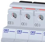
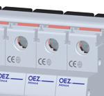
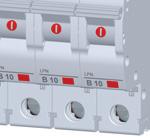
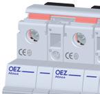
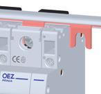
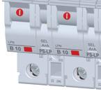
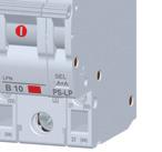
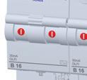
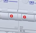
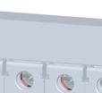
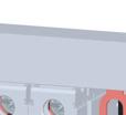
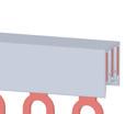
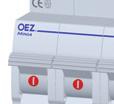
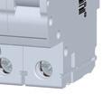
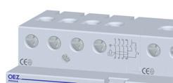
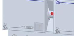
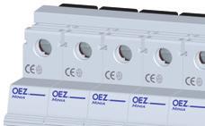
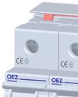
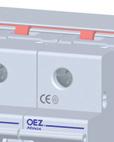
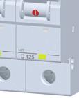
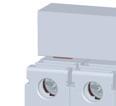
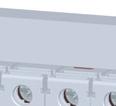
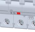
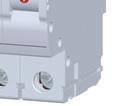
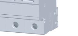
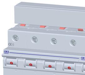
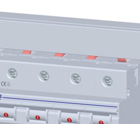
1 Residual current circuit breakers MINIA RESIDUAL CURRENT CIRCUIT BREAKERS WITH OVERCURRENT PROTECTION OLFE ( ka) The device is a combination of residual current circuit breaker and circuit breaker For building, housing and similar installations up to 40 A, 230 V a.c. For protection: against dangerous contact with live parts (I Δn 30 ma) against dangerous contact with dead parts against fire against overload against short circuit (breaking capacity I cn = ka) They react to sine-wave residual current (type AC) Tripping characteristics B, C according to EN 0898 Possibility of additional mounting of auxiliary switches PS-OLF-000 on the right side of the device Residual current circuit breakers with overcurrent protection I Δn I n Characteristic B Characteristic C Number Weight Package [ma] [A] Type Product code Type Product code of modules [kg] [pcs] 30 OLFE-B-N-030AC OLFE-C-N-030AC OLFE-0B-N-030AC OLFE-0C-N-030AC OLFE-B-N-030AC 3483 OLFE-C-N-030AC OLFE-20B-N-030AC OLFE-20C-N-030AC OLFE-2B-N-030AC OLFE-2C-N-030AC OLFE-32B-N-030AC OLFE-32C-N-030AC OLFE-40B-N-030AC 3483 OLFE-40C-N-030AC Accessories to OLFE Auxiliary switch PS-OLF-000 page C Busbar G2L-000- page D4 Connecting adapters AS-2-G, AS-0-S-AL page D9 Specification Type OLFE Standards EN 009- Approval marks Number of poles 2 Tripping characteristics B, C Type AC Rated current I n 40 A Rated residual current I Δn 30 ma Rated operating voltage U e 230 V a.c. Min. operating voltage ) U min 00 V a.c. Max. operating voltage U max 2 V a.c. Rated frequency f n 40 0 Hz Surge resistance (8/20 μs) 20 A Rated short-circuit breaking capacity I cn ka Rated residual making and breaking capacity I Δm 7. ka Rated pulse withstand voltage (.2/0 μs) U imp kv Mechanical endurance operating cycles Electrical endurance operating cycles Energy limitation class 3 Degree of protection IP20 Mounting on U rail according to EN 07 - type TH 3 Connection Conductor - rigid (solid, stranded) 2 mm 2 (upper terminal) 3 mm 2 (lower terminal) Conductor - flexible mm 2 (upper terminal) 2 mm 2 (lower terminal) Torque 3 Nm (upper terminal) 4 Nm (lower terminal) Opposite yes Operating conditions Ambient temperature - C 40 C Working position arbitrary Seismic immunity 3 g / 8 0 Hz ) For preserving the function of the test push-button C2
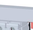
2 Residual current circuit breakers MINIA RESIDUAL CURRENT CIRCUIT BREAKERS WITH OVERCURRENT PROTECTION OLFE ( ka) Internal impedance Z and powers loss P Correction of rated currents I n Z ) P ) I n Correction of rated currents for ambient temperature C up to + 40 C [A] 2) [A] [mω/pole] [W/pole] [A] - C 0 C 0 C 20 C 30 C 40 C ) Mean values 2) Reference temperature: 30 C Dimensions OLFE Diagram OLFE N N 2 C3
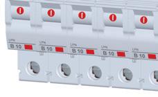
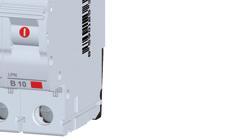
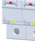
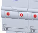
3 Residual current circuit breakers MINIA RESIDUAL CURRENT CIRCUIT BREAKERS WITH OVERCURRENT PROTECTION OLFE ( ka) Characteristics Characteristic B: for protection of electrical circuits with equipment which does not cause current surges (lighting and socket circuits etc.). The short-circuit release is set to (3 ) I n Characteristic C: for protection of electrical circuits with equipment which causes current surges (bulb lamp groups, motors etc.). The short-circuit release is set to ( 9) I n In.4 In At ambient temperature +30 C min t[s] v B C B C x I n Tripping characteristics of circuit breakers according to EN 0898 Thermal release Tripping characteristic type Tripping characteristic type Electromagnetic release B, C B C Conventional non-tripping current I nt for t h I nt =.3 I n Current I 4 for 0. s < t < 4 s (for I n 32 A) Conventional tripping current It for t < h I t =.4 I n 0. s < t < 90 s (for I n > 32 A) I 4 = 3 I n Current I 3 for s < t < 0 s (for I n 32 A) 0. s < t < s (for I I 3 = 2. I n 32 A) s < t < 20 s (for n In > 32 A) 0. s < t < 30 s (for I n > 32 A) I 4 = I n t - break time of the circuit breaker Current I for t < 0. s I = I n I = 0 I n t - break time of the circuit breaker C4

![overload protection circuit breaker with overload protection Type Product Arrangement Number Weight Package code of contacts ) of modules [kg] [pcs] PS-OLF-000](/docs-images/80/82204013/images/4-1.jpg "34843 00")

![breakers Accessories to Type Product Arrangement Number Weight Package code of contacts ) of modules [kg] [pcs] OFI, OFE up to 80 A PS-OF-00 3309 0.](/docs-images/80/82204013/images/4-4.jpg "0.07 OFI 00")
 Each digit indicates successively the number of make and break contacts Specification Type PS-OLF-000 PS-OF-00 PS-OF2-00 Standards EN 209 EN 0947-- EN")
 MCB A, char.")
 fuse A gg fuse A gg fuse A gg Electrical endurance 0 000 operating cycles 0 000 operating cycles 0 000 operating cycles Degree of protection IP20 IP20")
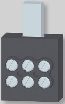
4 AUXILIARY SWITCHES Residual current circuit breakers MINIA Auxiliary switch for residual current circuit breakers with overcurrent protection Accessories to OLFI and OLFE For signalling the position of contacts of residual current Installation: : on the right side of the residual current circuit breakers with overload protection circuit breaker with overload protection Type Product Arrangement Number Weight Package code of contacts ) of modules [kg] [pcs] PS-OLF ) Each digit indicates successively the number of make, break and break-make contacts Auxiliary switch for residual current circuit breakers Accessories to OFI and OFE Installation: on the right side of the residual current circuit breaker For signalling the position of contacts of residual current circuit breakers Accessories to Type Product Arrangement Number Weight Package code of contacts ) of modules [kg] [pcs] OFI, OFE up to 80 A PS-OF OFI 00, 2 A PS-OF ) Each digit indicates successively the number of make and break contacts Specification Type PS-OLF-000 PS-OF-00 PS-OF2-00 Standards EN 209 EN EN 209 EN 209 EN Approval marks Arrangement of contacts ) 00 Rated operating U e /I e AC V a.c. / A 230 V a.c. / A voltage / current AC- 230 V a.c. / A 230 V a.c. / 3, A - DC V d.c. / 0, A, 220 V d.c. / A 220 V d.c. / 0, A 24 V d.c. / 4 A Min. voltage / current 24 V a.c. / 0 ma 24 V a.c. / 0 ma 24 V a.c. / 0 ma Short-circuit protection 2) MCB A, char. B or C MCB A, char. B or C 2) MCB A, char. B or C 2) fuse A gg fuse A gg fuse A gg Electrical endurance operating cycles operating cycles operating cycles Degree of protection IP20 IP20 IP20 Mounting on the right side of the device on the right side of the device on the right side of the device Connection Conductor - rigid (solid, stranded) 2. mm 2, 2x. mm mm mm 2 Conductor - flexible mm mm mm 2 Torque 0. Nm 0.8 Nm 0.8 Nm Opposite yes yes yes Operating conditions Ambient temperature -2 C 40 C -2 C 4 C -2 C 4 C Working position arbitrary arbitrary arbitrary ) Each digit indicates successively the number of make, break and break-make contacts 2) MCB - Miniature Circuit Breaker C
5 Residual current circuit breakers MINIA AUXILIARY SWITCHES Dimensions PS-OLF PS-OF PS-OF Diagram PS-OLF-000 PS-OF-00 PS-OF C


6 Residual current circuit breakers MINIA BASIC TERMS AND SYMBOLS Rated residual operating current I Δn is the value of residual current I Δn specified by the manufacturer, at which the residual current circuit breaker must switch out under specified conditions. Alternating residual current must by cut off by the residual current circuit breaker within (0. ) I Δn Rated current I n is the value of current specified by the manufacturer, which can be transferred by the residual current circuit breaker continuously. So the current I n can pass through the contacts for an unlimited time. Therefore it is, for instance, possible to use a residual current circuit breaker with I n =2 A in the circuit with max. current up to 2 A. For protection against overload of the residual current circuit breakers OFI, OFE, it is recommended to use the circuit breakers LSN, LST, LSE with rated current I n MCB I n RCCB Rated operating voltage U e is the voltage the residual current circuit breaker is to be connected to and which properties are related to. The connected voltage has no effect on the device function but on the function of the test circuit and isolation properties. Rated frequency f n is the frequency the residual current circuit breaker is designed for and at which it works correctly under stated conditions. Majority of residual current circuit breakers are designed for f n = 0 to 0 Hz. As the residual current circuit breaker function is based on the induction principle, the residual current behaviour and frequency show an effect upon tripping. When using a device designed for 0/0 Hz in a network with a different frequency, the user must count on a change of the tripping threshold i.e. a change of I Δn Conditional short-circuit current I nc short-circuit strength. The function and design principle does not allow to use the residual current circuit breaker for protection against short circuit. For circuit protection it is necessary to use a circuit breaker or a fuse. These elements cut the short-circuited circuit safely off. The residual current circuit breaker must only withstand the through-going short-circuit current. The amplitude of the maximum through current is defined as rated conditional short-circuit current I nc. The short-circuit strength is then expressed by the current I nc. For example, on the rating plate I nc = 0 ka is expressed by the following symbol: Ambient temperature T for the residual current circuit breakers is (- +40) C according to almost all international standards. Some residual current circuit breakers work in an extended range (-2 +40) C. This possibility is identified by the following symbol on the rating plate: Residual current circuit breaker type AC reacts to sine-wave residual current it is used in conventional AC networks Residual current circuit breaker type A reacts to sine-wave alternating and pulsating direct residual currents - it is used in conventional AC networks and the networks with phase power regulation etc. Residual current circuit breaker type G special residual current circuit breaker reducing the number of undesirable cut-offs. It is mainly installed before the devices causing short-time (up to 0 ms) stray currents. Identification: G Surge resistance: 3 ka (8/20 μs) Release delay: 0 ms G Residual current circuit breaker type S special residual current circuit breaker, which is mainly intended for selective switching of residual current circuit breakers and reduction of undesirable cut-offs. It is installed before the devices causing short-time (up to 40 ms) stray currents. Identification: S Surge resistance: ka (8/20 μs) Release delay: 40 ms S Selective (discriminating) switching means that if the residual current circuit breakers are connected in series, only the device in which circuit a failure occurs will cut off the current. More specifically, only the device in which the tripping residual current appears due to a failure in the protected circuit will turn off the current. The advantage consists in maintaining the power supply in the other circuits not affected by the failure. Such function of the protected circuit is achieved by connection of the selective residual current circuit breaker (see Fig. ) before the standard or G type residual current circuit breaker, with the following ratio of rated residual current: I Δn S 3 x I Δn -,G I ΔnS Rated residual operating current of the selective residual current circuit breaker I Δn -,G Rated residual operating current of standard or G type residual current circuit breaker The main reason of selective disconnecting of circuits is higher time delay of the selective residual current circuit breakers in tripping (compared to standard or G type ones). load I ΔnS = 0.3 A I Δn- = 0. A I = 0.03 A ΔnG load Fig. : Simplifi ed example of selective connection of residual current circuit breakers Residual current circuit breaker with overcurrent protection - the device is a combination of residual current circuit breaker and circuit breaker with 2-module width - it saves the space in the switchboard compared to conventional connection of two separate devices (3 modules). This eliminates the problem of primary protection and interconnection. The disadvantage of such a design compared to conventional one is that it is not possible to identify whether the tripping was actuated by the residual current circuit breaker or by the circuit breaker. C


![outlets [mm 2 ] 2 0 GL-30-0 3732 - ) 0.008 0 GL-30-373 - ) 0.02 0 0 GL-0-0 3733-0.](/docs-images/80/82204013/images/7-4.jpg "023 0 GL-0-3737 - 0.037 0 0 GL-20-0 3734-2 0.04 0 GL-20-3738 - ) 0.")
 37 24 GL--000-24 3730-0.307 0 2 2x 28 G2L-000-373 EKC-2+3 0.")
 0.")


 The busbar is manufactured as enclosed one 2) For single-pole devices with")


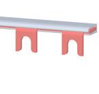
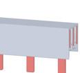
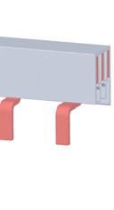
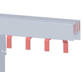
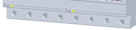
7 INTERCONNECTING BUSBARS Interconnecting busbars For interconnection of to 4-pole circuit breakers, tumbler switches, residual current circuit breakers, lightning current arresters and surge voltage arresters For interconnection of a series of single-phase or threephase circuit breakers and tumbler switches, on which an auxiliary switch is mounted switch fork pin Busbars GL-.., G2L-.., G3L-.., G4L-.. with forks into the head part of the terminal, Busbars SL-.., S2L-.., S3L-.., S4L-.. with pins into the clamp part of the terminal Busbar Number Output Number Cross-section Type Product End cap Weight Package shape of poles spacing [mm] of outlets [mm 2 ] 2 0 GL ) GL ) GL GL GL GL ) GL EKC GL ) GL x 28 G2L EKC x 2 0 G3L ) G3L ) G3L x G3L G3L x G3L ) x 9 0 G3L-000-0C 373 EKC G3L-000-C 3739 EKC x G3L EKC x G4L EKC x G3L+N EKC SL ) SL EKC SL EKC SL EKC SL x 28 S2L EKC x 9 S3L EKC S3L EKC x 2 2 S3L EKC x 9 2 S4L EKC ) The busbar is manufactured as enclosed one 2) For single-pole devices with auxiliary switch Accessories End caps For covering the ends of connecting busbars Type Product Description Weight Package EKC for -pole rails cross-section 0, 2, mm EKC for 2-pole rails and for 3-pole rails cross-section mm EKC for 3-pole rails cross-section 0 mm EKC for 3-pole rails and for 4-pole rails cross-section 2 mm EKC for 4-pole rails cross-section mm Power supply unit It enables power supply of interconnecting busbars by conductors of cross section up to 3 mm 2 The blocks can be assembled in series to create a multipole connection unit. Degree of protection IP20 Type Product Weight Package ES-3-GS D4
8 INTERCONNECTING BUSBARS Specification Type G.., S.. Rated operating voltage U e 4 V a.c. Max. operating voltage U max 00 V a.c. Loading current 3 80 A Cross-section 0 2 mm 2 Short-circuit strength with primary fuse 20 A gg 0 ka Overvoltage category III Busbar material E-Cu-F2 Insulation material PC/ABS-Blend Max. loading current per phase Rail cross-section 0 mm 2 2 mm 2 mm 2 20 mm 2 24 mm 2 2 mm 2 Power supply from the rail edge 3 A A 80 A 90 A 00 A 00 A Power supply from the rail centre ) 00 A 0 A 30 A 0 A 0 A 80 A ) Max. loading current in one direction must not be higher than max. loading current at power supply from the rail edge Diagram GL-.., SL-.. G2L-.., S2L-.. G3L-.., S3L-.. G4L-.., S4L-.. G3L+N-.. L L L2 (N) L L2 L3 L L2 L3 N L N L2 N L3 N D
9 INTERCONNECTING BUSBARS Dimensions GL-30-0, GL-0-0, GL-20-0 GL x 7 2. G-L--000/ x G2L x (GL-30-0) 0 (GL-0-0) 20 (GL-20-0) 99.8 x GL-30-, GL-0-, GL-20- GL (GL-30-) 0 (GL-0-) 20 (GL-20-) G3L-0-0, G3L-0-0, G3L-20-0 G3L-000-0C x 9 G3L-0-, G3L-0-, G3L-20- G-3L-000/C x (G3L-0-0) 0 (G3L-0-0) 20 (G3L-20-0) 0 (G3L-0-) 0 (G3L-0-) 20 (G3L-20-) G3L x 2.8. G4L-000-, G3L+N x D
10 INTERCONNECTING BUSBARS Dimensions SL-20- SL x x SL-000- x SL x SL S2L-000- x x S3L-000- S3L x x S3L S4L x x ES-3-GS D7
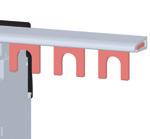
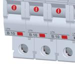


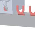
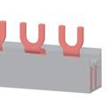

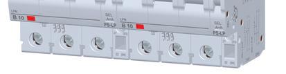

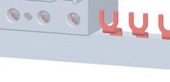
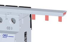


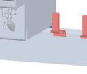
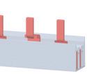
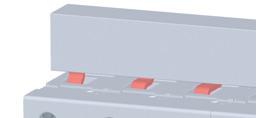
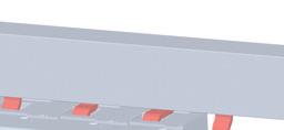
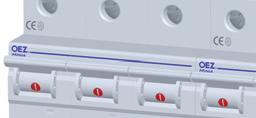
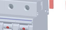
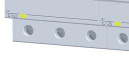

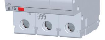
11 INTERCONNECTING BUSBARS Examples of use of interconnecting busbars INTERCONNECTING BUSBARS WITH FORKS -pole interconnecting busbars For interconnection of -pole devices in the head part of the terminal Use: LPE, LPN, SJB, SVL, SVM, APN -pole interconnecting busbars with spacing mm For interconnection of -pole devices with auxiliary switch in the head part of the terminal Use: LPE, LPN, APN 2-pole interconnecting busbars For interconnection of 2-pole devices in the head part of the terminal Use: LSN, LSE, SVL, SJL, ASN 3-pole interconnecting busbars For interconnection of 3-pole devices in the head part of the terminal Use: LPE, LPN, SJB, SVL, SVM, APN 3-pole interconnecting busbars with a gap on the auxiliary switch For interconnection of 3-pole devices with auxiliary switch in the head part of the terminal Use: LPE, LPN, APN 4-pole interconnecting busbars For interconnection of 4-pole devices in the head part of the terminal Use: LPE, LPN, OFI, OFE, APN INTERCONNECTING BUSBARS WITH PINS -pole interconnecting busbars For interconnection of -pole devices in clamp part of the terminal Use: LPE, LPN, SJB, SVL, SVM, APN -pole interconnecting busbars with spacing mm For interconnection of -pole circuit breakers LST in clamp part of the terminal or for interconnection of -pole devices with auxiliary switch in clamp part of the terminal Use: LPE, LPN, LST, APN, AST 2-pole interconnecting busbars For interconnection of 2-pole devices in clamp part of the terminal Use: LPE, LPN, OLFE, OLFI, OFE, OFI, APN 3-pole interconnecting busbars For interconnection of 3-pole devices in clamp part of the terminal Use: LPE, LPN, APN 3-pole interconnecting busbars with spacing mm For interconnection of 3-pole circuit breakers LST in clamp part of the terminal or for interconnection of -pole devices with auxiliary switch in clamp part of the terminal Use: LPE, LPN, LST, APN, AST 4-pole interconnecting busbars with spacing mm For interconnection of 4-pole circuit breakers LST in clamp part of the terminal Use: LST, AST D8


12 CONNECTING ADAPTERS Connecting adapter up to 2 mm 2 with fork For connection of another conductor to the head part of the terminal of a circuit breaker, residual current circuit breaker, tumbler power switch etc. For example, the best solution is to connect a conductor for power supply of an electric meter in the clamp part of the circuit breaker terminal, and another conductor through the connecting adapter AS-2-G in the head part of the circuit breaker terminal Conductor cross-section: 2 mm 2 Type Product Accessories Weight Package AS-2-G LPE, LPN, OLFI, OLFE, OFI, OFE, SJB, SVM, APN Connecting adapter up to 2 mm 2 with pin Accessories to: OFI20, OFE20, SVL, SJL, RP Conductor cross-section: 2 mm 2 For connection of conductors to the clamp part of the terminal Type Product Accessories Weight Package AS-2-S OFI , OFE , RLP Connecting adapter up to 0 mm 2 For connection of Al or Cu conductors Cross-section of Cu conductors: 2. 0 mm 2 Cross-section of Al conductors: 0 mm 2 Type Product Accessories Weight Package AS-0-S-AL 3739 LPE, LPN, LST, SJBplus, APN, AST 0.08 Connecting adapters up to 9 mm 2 For connection of Cu/Al conductors of cross section 3 9 mm 2 With direct or outbowed terminal Type Product Accessories Weight Package CS-FH000-3NP straight guidon the package contains the set of 3 pieces LST, SJBplus, SJB-NPE, AST 0. CS-FH000-NP9 378 straight guidon LST, SJBplus, SJB-NPE, AST 0.0 CS-FH000-3NV outbowed guidon the package contains the set of 3 pieces LST, SJBplus, SJB-NPE, AST 0.84 Connecting adapter 3x0 mm 2 For connection of 3 conductors / device pole of cross section 0 mm 2 Type Product Accessories Weight Package N3x0-FH000 LST, SJB, SVM, AST 0.03 D9


13 CONNECTING ADAPTERS Dimensions AS-2-G AS-2-S AS-0-S-AL N3x0-FH CS-FH NP9 24 CS-FH000-3NV Examples of use of connecting adapters and blocks AS-2-G For connection of another conductor of cross section up to 2 mm 2 to the head part of the terminal Use: LPE, LPN, OLFI, OLFE, OFI, OFE, SJB, SVM, APN AS-2-S For connection of conductors of cross section up to 2 mm 2 to the clamp part of the terminal Use: OFI , OFE , RLP AS-0-S-AL For connection of Cu/Al conductors of cross section up to 0 mm 2 to the clamp part of the terminal Use: LSN, LST, LSE, LFI, LFE, SJBplus, ASN, AST CS-FH000-3NP9, CS-FH000-NP9, CS-FH000-3NV9 For connection of Cu/Al conductors of cross section up to 9 mm 2 to the clamp part of the terminal Use: LST, SJBplus, SJB-NPE, AST N3x0-FH000 For connection of three conductors of cross section 0 mm 2 to the clamp part of one terminal Use: LST, SJB, SVM, AST D70
RESIDUAL CURRENT CIRCUIT BREAKERS OFI (10 ka)
") Residual current circuit breakers RESIDUAL CURRENT CIRCUIT BREAKERS OFI (10 ka) They react to both alternating sine-wave residual current and pulsating direct current (type A) For protection: against accidental
Residual current circuit breakers RESIDUAL CURRENT CIRCUIT BREAKERS OFI (10 ka) They react to both alternating sine-wave residual current and pulsating direct current (type A) For protection: against accidental
RESIDUAL CURRENT CIRCUIT BREAKERS OFE (6 ka)
") Residual current circuit breakers RESIDUAL CURRENT CIRCUIT BREAKERS OFE ( ka) Standard type for common use in building and housing installations up to 3 A, 230/400 V a.c. They react to alternating sine-wave
Residual current circuit breakers RESIDUAL CURRENT CIRCUIT BREAKERS OFE ( ka) Standard type for common use in building and housing installations up to 3 A, 230/400 V a.c. They react to alternating sine-wave
Residual current circuit breakers with conditional shortcircuit
 LFE Residual current circuit breakers RESIDUAL CURRENT CIRCUIT BREAKERS LFE Residual current circuit breakers with conditional shortcircuit current 6 ka. They react to sine-wave residual current (type
RESIDUAL CURRENT CIRCUIT BREAKERS WITH OVERCURRENT PROTECTION OLE
 OLE Residual current circuit breakers RESIDUAL CURRENT CIRCUIT BREAKERS WITH OVERCURRENT PROTECTION OLE OLE-10B-1N-030AC The device is a combination of residual current circuit breaker and circuit breaker.
Basic function. Rated current. Appropriate for three-phase motors of output 2) [kw] I n. = 400 V a.c. 2) Appropriate for three-phase motors
![Basic function. Rated current. Appropriate for three-phase motors of output 2) [kw] I n. = 400 V a.c. 2) Appropriate for three-phase motors](/thumbs/74/70162763.jpg "Basic function. Rated current. Appropriate for three-phase motors of output 2) [kw] I n. = 400 V a.c. 2) Appropriate for three-phase motors") MOTOR STARTERS SM Basic function Switching and protection of motors up to A Protection against short-circuit and protection against overload The device responds to phase failure The device is provided
MOTOR STARTERS SM Basic function Switching and protection of motors up to A Protection against short-circuit and protection against overload The device responds to phase failure The device is provided
Varius SUMMARY OF MODELS
 SUMMARY OF MODELS Type 10 14 22 OPT22/OPT20 OPVF10 Rated operating current I e / Rated current I n 32 A / - 63 A / - 125 A / - 63 A / - - / 30 A Rated operating voltage U e / Rated voltage U n AC 690 V
Varius SUMMARY OF MODELS
 Varius SUMMARY OF MODELS Type FH00 FH1 FH2 FH3 LTL4a Rated operating current I e 160 A 160 A 250 A 400 A 630 A 1 600 A Rated operating voltage AC/DC U e 690 V 690 V 690 V 690 V 690 V 690 V Size 000 00
Devices for switching and control
 Devices for switching and control WWWOEZCOM Motor starters MOTOR STARTERS SM Basic function Switching and protection of motors up to 2 A Protection against short-circuit and protection against overload
max pole for t=15 ms
 Types RI 61 RI 61N RI 61J RI 62 RI 62J RI 63 RI 63N RI 64 single-pole single-pole + neutral pole single-pole (for DC circuits) two-pole two-pole (for DC circuits) three-pole three-pole + neutral pole three-pole
Fuse switch-disconnectors
 Fuse switch-disconnector FH000 is intended for fuse-links with blade contacts size 000. It enables safe disconnection not only of rated current, but also overcurrent up to octuple rated current. A version
IP20 degree of protection; IP40 degree of protection after installation in a distribution box
 RI 50 RI 50 is used for the protection of installations and devices (overload and short circuit), and as a disconnector in case of electric shock Simple and quick fixing to a 35 mm mounting rail in accordance
Selective main circuit breakers S 750 series Technical Data
 Selective main circuit breakers S 750 series Technical Data When connecting aluminium conductors ( 4 mm 2 ) ensure that the contact surfaces of the conductors are cleaned, brushed and treated with grease.
COMMERCIAL INFORMATION TECHNICAL INFORMATION BA511*33
 BA511*33 COMMERCIAL INFORMATION Type designation specification for ordering...146 (design and circuit breaker and switch-disconnector accessories selection, circuit breaker rated current selection) Connecting
Varius SUMMARY OF MODELS
 SUMMARY OF MODELS FH000 FH00 FH FH2 FH LTL4a Rated operating current I e 60 A 60 A 250 A 400 A 60 A 600 A Rated operating voltage AC/DC U e 690 V 690 V 690 V 690 V 690 V 690 V Size 000 00 2 4a Fuse-link
Overcurrent releases - description, specifications, characteristics specifications specifications description...
 BA5*37 COMMERCIAL INFORMATION Type designation specification for ordering...68 (design and circuit breaker and switch-disconnector accessories selection, circuit breaker rated current selection) Connecting
Low Voltage A GE Power Controls Company. General catalogue
 Low Voltage A GE Power Controls Company General catalogue this is a blanc page Miniature circuit breakers A Miniature circuit breakers AC miniature circuit breakers Benefits of the new MCB s A 3 The AEG
MS25, MST25, MS20, MST20
 Versions: - MS25 with thermal and magnetic releases - MST25 with a thermal release - MS20 - with thermal and magnetic releases for single-phase consumers - MST20 with a thermal for single phase consumers
Modeion MOULDED CASE CIRCUIT BREAKERS BL1600S
 H MOULDED CASE CIRCUIT BREAKERS BL6S H BL6S COMMERCIAL INFORMATION Switching units, withdrawable device...h4 Overcurrent releases...h5 Signalling units...h5 Residual current monitor...h6 Current transformers
MS25, MST25, MS20, MST20
 Motor protection switches MS25, MST25, MS20, MST20 Versions: - MS25 with thermal and magnetic releases - MST25 with a thermal release - MS20 - with thermal and magnetic releases for single-phase consumers
W Datasheet: Residual current circuit breaker, series PRIORI, 10kA, Typ B
 W Datasheet: Residual current circuit breaker, series PRIORI, 10kA, Typ B W SCHRACK-INFO All-current sensitive RCCB ( type B, B+ and Bfq) B+ types also meet the requirements of superior fire-protection
System pro M compact Miniature Circuit Breaker SU200 M for branch circuit protection acc. to UL 489
 Data Sheet System pro M compact for branch circuit protection acc. to UL 489 2CDC021004S0014 2CDC021046S0014 The miniature circuit breaker SU200 M is BB s solution for UL 489 branch circuit protection
Fuse switch-disconnectors
 Fuse switch-disconnector FH00 is intended fuse-links with blade contacts size 000 and 00. It enables safe disconnection not only of rated current, but also overcurrent up to octuple rated current. A version
MOULDED CASE CIRCUIT BREAKERS BC160N
 D MOULDED CASE CIRCUIT BREAKERS BC160N D BC160N COMMERCIAL INFORMATION Circuit breakers...d4 Switch-disconnectors...D5 Connecting sets......d6 Mounting sets......d6 Switches...D7 Shunt trips...d7 Undervoltage
Index. Manual Motor Starters 1. Auxiliary Contact Blocks 1. Trip Alarm Auxiliary 1. Switch. Shunt Release 1. Under-voltage Release 2.
 Index Index Page Manual Motor Starters 1 Auxiliary Contact Blocks 1 Trip Alarm Auxiliary 1 Switch Shunt Release 1 Under-voltage Release 2 Accessories 2 Busbar Connectors 2 Enclosures 2 Leistung, kw C mv
D509E. Manual Motor - Starters
 D509E Manual Motor - Starters Index Page Manual Motors Starters 182 Auxilliary Contact Blocks 182 Trip Alarm Aux. Switch 182 Shunt Release 182 Under-voltage Release 183 Accessories 183 Busbar Connectors
Residual current devices
 Residual devices FH00 Plus of range /30 Technical features table /3 Ordering information /34 Technical details /37 DS01 and DS0C Plus of range /38 Technical features table /40 Ordering information DS01
System pro M compact Miniature Circuit Breaker SU200M for branch circuit protection acc. to UL 489
 System pro M compact Miniature Circuit Breaker SU200M for branch circuit protection acc. to UL 489 2CDC021004S0014 2CDC021046S0014 The miniature circuit breaker SU 200 M is ABB s solution for UL 489 branch
RCBOs - Residual current circuit breakers with integral overcurrent protection KZS
 RCBOs - Residual current circuit breakers with integral overcurrent protection KZS Advantages of residual current circuit breakers with integral overcurrent protection KZS - 1M Combining the features of
Characteristics of LV circuit breakers Releases, tripping curves, and limitation
 Characteristics of LV circuit breakers Releases, tripping curves, and limitation Make, Withstand & Break Currents A circuit breaker is both a circuit-breaking device that can make, withstand and break
Miniature Circuit-Breakers (MCBs)
") Product Overview Miniature Circuit-Breakers (MCBs) Design Tripping characteristics Rated current I n Rated breaking capacity Power supply company product range 5SP3 E 16 - A Standard product range 5SQ2
Product Overview Miniature Circuit-Breakers (MCBs) Design Tripping characteristics Rated current I n Rated breaking capacity Power supply company product range 5SP3 E 16 - A Standard product range 5SQ2
Electronic circuit breaker EBU10-T
 Description The electronic circuit protector type EBU10-T (Electronic Breaker Unit) provides selective overcurrent protection in AC 230 V UPS systems. It consists of an MCB approved for short circuit interruptions
DSE201 Compact design with enhanced protection
 DSE201 Compact design with enhanced protection The best of safety DSE201 6 ka: the highest level of reliability The 1P+N electronic residual current circuit-breakers with overcurrent protection (RCBOs)
TX³ RCCBs 2P up to 100 A
 87045 LIMOGES Cedex Telephone number: +33 (0)5 55 06 87 87 Fax: +33 (0)5 55 06 88 88 TX³ RCCBs CONTENTS PAGE 1. Description, use... 1 2. Range... 1 3. Overall dimensions... 1 4. Preparation - Connection...
All round protection guaranteed
 s With SLR ll round protection guaranteed Betagard MCB 5SL Inspiring Safety nswers for infrastructure. Overview s a culture Siemens has always endeavoured to introduce innovative products worldwide. The
MOULDED CASE CIRCUIT BREAKERS BH630N, BH630S
 MOULDED CASE CIRCUIT BREAKERS BH6N, BH6S F BH6N, BH6S COMMERCIAL INFORMATION Switching units, withdrawable device, plug-in device...f4 Switch-disconnector unit...f6 Connecting sets...f7 Mounting sets...f9
Miniature Circuit-Breakers (MCBs)
") Product overview Miniature Circuit-Breakers (MCBs) Design Tripping characteristic Rated currents I n Rated breaking capacity Power supply company product range 5SP3 E 16 - A Standard product range 5SX2
Product overview Miniature Circuit-Breakers (MCBs) Design Tripping characteristic Rated currents I n Rated breaking capacity Power supply company product range 5SP3 E 16 - A Standard product range 5SX2
Technical Data. Miniature circuit-breakers for branch circuit protection according to UL 489, CSA C 22.2 No. 5
 Technical Data Miniature circuit-breakers for branch circuit protection according to UL 489, CSA C 22.2 No. 5 When connecting aluminum conductors, ensure that the contact surfaces of the conductors are
Page. Circuit-Breakers M4 2 for motor protection. Auxiliary contacts 3 Signalling switch Auxiliary releases
 Circuit Breakers M4 Page Circuit-Breakers M4 2 for motor protection Auxiliary contacts 3 Signalling switch Auxiliary releases Insulated 3-pole busbar system 4 Terminal block DIN-rail adapters 5 Busbar
Miniature Circuit Breaker
 Introduction - Miniature Circuit Breaker (MCB) SALIENT FEATURES SALIENT FEATURES Standards MCBs conform to the latest standard IS 8828: 1996/IEC: 898 1995 Mid-Trip Position The Mid trip position of the
Technical Data Accessories MCBs Ex9B.
 Auxiliary and signal contact units AX31, A31, AX31 General parameters With one circuit breaker Ex9B., it can be used up to three contact units with single CO contact or up to two contact units with 2 CO
TeSys contactors. Use in category DC-1 (resistive loads; time constant L/R y 1 ms) Rated operational current Ie. to be wired in series
 Rated operational current Ie. to be wired in series") Selection 3-pole shockproof contactors FG d.c. supply Selection guide for utilisation categories DC-1 to DC-5 Use in category DC-1 (resistive loads; time constant L/R y 1 ms) Rated operational current
Selection 3-pole shockproof contactors FG d.c. supply Selection guide for utilisation categories DC-1 to DC-5 Use in category DC-1 (resistive loads; time constant L/R y 1 ms) Rated operational current
Main catalogue. Distribution Innovation
 Main catalogue Distribution Innovation Contents The family... 2 3 Miniature circuit-breakers - General, technical data... 6 9 - Order data... 10 19 Residual current operated circuit-breakers - Residual
Residual Current Protective Devices / Arc Fault Detection Devices (AFDDs)
") Introduction Overview Devices Page Application Standards Used in / Personnel, material and fire protection, as well as protection against direct contact. SIGRES with active condensation protection for
Introduction Overview Devices Page Application Standards Used in / Personnel, material and fire protection, as well as protection against direct contact. SIGRES with active condensation protection for
87045 LIMOGES Cedex. 2. PRODUCT RANGE (continued) 1. DESCRIPTION - USE. Breaking capacity : Symbol : Technology : 3. OVERALL DIMENSIONS
 1. DESCRIPTION - USE. Breaking capacity : Symbol : Technology : 3. OVERALL DIMENSIONS") 87045 LIMOGES Cedex Phone : + 33 5 55 06 87 87 Fax : + 33 5 55 06 88 88 R.C.B.O. DX 6000 A Phase + Neutral,, neutral on right side Cat. n (s) : 077 31 077 44-077 77 077 84 078 79 079 01-083 95 084 06 084
87045 LIMOGES Cedex Phone : + 33 5 55 06 87 87 Fax : + 33 5 55 06 88 88 R.C.B.O. DX 6000 A Phase + Neutral,, neutral on right side Cat. n (s) : 077 31 077 44-077 77 077 84 078 79 079 01-083 95 084 06 084
Latch for Contactors 4-pole see page 36. Ratings Rated Aux. Contacts Type Coil voltage 2) AC2 Current Built-in Additional 24 24V= DC 5
 AC2 Current Built-in Additional 24 24V= DC 5") 3-pole DC Operated Ratings Rated Aux. Contacts Type Coil voltage 1) AC2 Current Built-in Additional 24 24V= DC 5 AC3 see 48 60V= DC 6 380V AC1 page 34 110 110V= DC 7 400V 660V 220 220V= DC 8 415V 690V
3-pole DC Operated Ratings Rated Aux. Contacts Type Coil voltage 1) AC2 Current Built-in Additional 24 24V= DC 5 AC3 see 48 60V= DC 6 380V AC1 page 34 110 110V= DC 7 400V 660V 220 220V= DC 8 415V 690V
Modular contactor for installation into distribution boards
 Modular contactor for installation into distribution boards Description Modular contactors are used for installation in consumer units in dwellings, business premises, hotels, hospitals, shopping centres,
Residual Current Circuit-breaker (RCCB) FH 200 Series
 FH 200 Series") Residual Current Circuit-breaker (RCCB) FH 200 Series Bi-directional cylindrical terminal ensure higher safety of connecting operations, making them easier. Test pushbutton to verify the correct functioning
Residual Current Circuit-breaker (RCCB) FH 200 Series Bi-directional cylindrical terminal ensure higher safety of connecting operations, making them easier. Test pushbutton to verify the correct functioning
Thermal-magnetic Miniature Circuit Breaker 4230-T...
 Thermal-magnetic Miniature Circuit Breaker 420-T... Description Single pole and multipole thermal-magnetic miniature circuit breakers (MCBs) in accordance with EN 60947-2, UL 077 and UL 489 for DIN rail
and other modular devices for low voltage installation
 Technical catalogue System and other modular devices for low voltage installation 2CSC400002D0204 SUMMARY Introduction Miniature Circuit-Breakers Residual Current Devices Auxiliary elements and accessories
DNX 3 MCB 4500 A / 6 ka Phase + Neutral, neutral on left side
 87045 LIMOGES Cedex Telephone number: +33 (0)5 55 06 87 87 Fax: +33 (0)5 55 06 88 88 DNX 3 MCB 4500 A / 6 ka CONTENTS PAGE 1. Description, use... 1 2. Range... 1 3. Overall dimensions... 1 4. Preparation
Phase + Neutral, neutral on left side
 87045 LIMOGES Cedex Téléphone : 05 55 06 87 87 Télécopie : 05 55 06 88 88 DX 3 MCB 10000 A / 16 ka CONTENTS PAGE 1. Description, use...1 2. Range...1 3. Overall dimensions...1 4. Preparation - Connection...1
Technical data. Miniature Circuit Breakers. System pro M. System pro M
 Technical data System pro M System pro M 1 Prior to connection of aluminium conductors ensure that their contact points are cleaned, brushed and coated with grease. The contact terminals must be tighten
MS /27/2015. ABB contact for United States of America. General Information Extended Product Type: Categories
 Page 1 of 5 MS132-10 ABB contact for United States of America General Information Extended Product Type: Product ID: EAN: Catalog Description: Long Description: MS132-10 1SAM350000R1010 4013614400100 MS132-10
TECHNICAL DESCRIPTION
 DC Circuit Breaker TECHNICAL DESCRIPTION TRK5650523200 Ed.1 of 23/07/13 CONTENTS 1. INTRODUCTION... 2 2. DESCRIPTION... 2 2.1 Description of circuit breaker... 2 2.2 Operating mode... 2 2.3 Variants and
AF40... AF96 3-pole contactors Technical data
 Main pole - Utilization characteristics according to IEC Standards IEC 60947- / 60947-4- and EN 60947- / 60947-4- Rated operational voltage Ue max. 690 V Rated frequency (without derating) 50 / 60 Hz Conventional
COMBINATION CIRCUIT BREAKERS RCBO
 COMBINATION CIRCUIT BREAKERS RCBO W COMBINED MCB AND RCCB, SERIES BOLF W CONTACT POSITION INDICATOR 108 TYPE EAN CODE FOR QUICK ORDERING TRIP INDICATOR WHITE/BLUE CONTACT POSITION INDICATOR RED/GREEN W
Contactors KNL A 68 KNL6, KNL9, KNL12, KNL16, KNL18, KNL22, KNL30. Dimensional drawing of KNL KNL6, KNL9, KNL12, KNL16, KNL18 KNL22, KNL30
 Contactors KNL KNL6, KNL9, KNL12, KNL16, KNL18, KNL22, KNL30 Adaptable to various control requirements with ability of mounting from one to four additional auxiliary contacts. Versatile product capable
DX³ 4-pole RCBO 6000 A/10 ka
 87045 LIMOGES Cedex Telephone number: +33 (0)5 55 06 87 87 Fax: +33 (0)5 55 06 88 88 DX³ 4-pole RCBO CONTENTS PAGE 1. Description, use... 1 2. Range... 1 3. Overall dimensions... 1 4. Preparation - Connection...
Cat. N (s) : /65/66/83/84, /94/95/96/99, /01/02/06/07/11/12/13/14. Pollution degree : C / + 40 C. .
 : /65/66/83/84, /94/95/96/99, /01/02/06/07/11/12/13/14. Pollution degree : C / + 40 C. .") 87045 LIMOGES Cedex Telephone : (+33) 05 55 06 87 87 Fax : (+ 33) 05 55 06 88 88 R.C.C.B. s 0090 00/01/02/06/07/11/12/13/14 0/01/02/06/07/11/12/13/14/18/19/23/24/25/26/ /18/19/23/24/25/26/45/46 45/46 0090
87045 LIMOGES Cedex Telephone : (+33) 05 55 06 87 87 Fax : (+ 33) 05 55 06 88 88 R.C.C.B. s 0090 00/01/02/06/07/11/12/13/14 0/01/02/06/07/11/12/13/14/18/19/23/24/25/26/ /18/19/23/24/25/26/45/46 45/46 0090
Electronic overload relay EF65, EF96 and EF146
 Data sheet Electronic overload relay EF65, EF96 and EF146 Electronic overload relays are the alternative to the thermal overload relays. An electronic overload relay offers reliable and fast protection
Phase + Neutral, neutral on right side
 87045 LIMOGES Cedex Telephone number: +33 5 55 06 87 87 Fax: +33 5 55 06 88 88 DX 3 MCB 6000 A / 10 ka Cat.. N (s): 4 074 67 / 68 / 69 / 70 / 71 / 72 / 73 / 74 / 75 / 76 / 77 / 78 / 79 ; 4 077 33 / 34
MINIATURE CIRCUIT BREAKERS RCBO s & DIN RAIL MOUNTED FUSE HOLDERS
 MINIATURE CIRCUIT BREAKERS RCBO s & DIN RAIL MOUNTED FUSE HOLDERS MANUFACTURED IN THE EU EUROPEAN QUALITY 1, 2 & 3 POLE MCB s TRIPPING CURVES C & D CURRENT RATINGS 1AMP TO 63AMPS 10KA BREAKING CAPACITY
System pro M compact Miniature Circuit Breaker S 200 M UC for DC and AC applications
 Data Sheet System pro M compact Miniature Circuit Breaker S 200 M UC for DC and AC applications 2CDC021031S0011 2CDC021033S0011 The miniature circuit breaker S 200 M UC extends the established ABB System
Technical Information
 -100 Controller IEC Performance Data (CSA C22.2, UL 508 No. 14 in connection with a short-circuit protection device Catalog No. -100... 25A 40A 63A 90A Maximum Short-Circuit Current 480V [ka] 65 65 42
3VU13, 3VU16 Circuit-Breakers
 3VU3, 3VU6 Circuit-Breakers Description The 3VU3, 3VU6 circuit-breakers are compact circuit-breakers for currents up to 80 A which operate according to the current limiting principle. The devices are used
Circuit-Breakers M4 166 for motor protection. Auxiliary contacts 167 Signalling switch Auxiliary releases
 Index Page Circuit-Breakers M4 166 for motor protection Auxiliary contacts 167 Signalling switch Auxiliary releases Insulated 3-pole busbar system 168 Terminal block DIN-rail adapters 169 Busbar adapters
Electronic overload relays EF205 and EF370
 Data sheet Electronic overload relays EF205 and EF370 Electronic overload relays offer reliable protection in case of overload and phase-failure. They are the alternative to thermal overload relays. Motor
System pro M compact Supplementary protector S 200 PR for ring-tongue applications acc. to UL1077
 Data Sheet System pro M compact Supplementary protector S 200 PR for ring-tongue applications acc. to UL1077 2CDC021026S0011 2CDC021016S0012 The S 200 PR is a high-performance supplementary protector with
RESIDUAL CURRENT CIRCUIT BREAKER
 Quality Features Mid Trip - Different knob position to indicate whether the device is Switched OFF by a fault or Switched OFF manually Inscription Window - Ensures circuit identification and hence reduces
MOULDED CASE CIRCUIT BREAKERS BL1600S
 H MOULDED CASE CIRCUIT BREAKERS BL6S H BL6S COMMERCIAL INFORMATION Switching units, withdrawable device, plug-in device...h4 Overcurrent releases...h Signalling units...h Connecting sets...h6 Switches...H8
Interchangeable Built-in Fixed thermal Adjustable thermal Magnetic Fixed Adjustable Adjustable Electronic RMS 7 LS LSI
 . Technical Data and Specifications Ratings Frames EG, JG and LG EG JG LG Maximum rated current (amperes) 15, 160 1 50 400, 630 Breaker type 3 B B E S S H H C E S H C U X E S H C U X of poles 1, 3, 4,
Protection Equipment
 Protection Equipment Price Groups 101, 102, 121, 131, 143 /2 Introduction Motor Starter Protectors/ Circuit Breakers SIRIUS 3RV2 Motor Starter Protectors up to 40 A new /7 General data /13 For motor protection
Connecting sets CS-FS CS-FS123-WD. Connecting space covers OD-FS00-.. OD-FS123-KP. Adapter for parallel outlet - HP-SE/K
 Varius SUMMARY OF MODELS OF FUSE-RAILS Type FSR00 FSR1 FSR2 FSR3 Rated operating current I e 160 A 250 A 400 A 630 A Rated operating voltage AC/DC U e 690 V 690 V 690 V 690 V Size 00 1 2 3 Busbar spacing
DX³ RCBO 4500/6 ka Phase + Neutral, neutral on left
 87045 LIMOGES Cedex Telephone number: +33 5 55 06 87 87 Fax: +33 5 55 06 88 88 DX³ RCBO 4500/6 ka CONTENTS PAGE 1. Description, use... 1 2. Range... 1 3. Overall dimensions... 1 4. Preparation Connection...
Switch Disconnectors. SENTRON 3NP5 Fuse Switch Disconnectors up to 630 A. Introduction. 7/106 Siemens LV
 Switch Disconnectors Introduction Siemens AG 2010 Overview 3NP5 0 3NP5 2 3NP5 fuse disconnector range 3NP5 4 SENTRON 3NP5 fuse disconnectors are controls for the occasional manual ing/isolating of loads
Btdin RCBO 6000A up to 63A (2P)
") Index Pages 1. Descripton... 2 2. Product range... 2 3. Overall dimensions... 2 4. Fixing Connection... 3 5. Generl characteristics.... 4-29 6. Compliance - Approvals... 30 7. Curves... 30-34 8.Auxiliaries-
Index Pages 1. Descripton... 2 2. Product range... 2 3. Overall dimensions... 2 4. Fixing Connection... 3 5. Generl characteristics.... 4-29 6. Compliance - Approvals... 30 7. Curves... 30-34 8.Auxiliaries-
TECHNICAL DESCRIPTION
 DC Circuit Breaker TECHNICAL DESCRIPTION TRK5650515200 Ed.1 of 21/02/13 CONTENTS 1. INTRODUCTION... 2 2. DESCRIPTION... 2 2.1 Description of circuit breaker... 2 2.2 Operating mode... 2 2.3 Variants and
Thermal overload relay TF140DU and TF140DU-V1000
 Data sheet Thermal overload relay TF140DU and TF140DU-V1000 Thermal overload relays are economic electromechanical protection devices for the main circuit. They are used mainly to protect motors against
COMPLETE SOLUTIONS FOR POWER PROTECTION
 COMPLETE SOLUTIONS FOR POWER PROTECTION GLOBAL SPECIALIST IN ELECTRICAL AND DIGITAL BUILDING INFRASTRUCTURES Modular protection P. 8 RX 3 MCBs 63 A 4500 & 6000 P. 18 DX 3 -IS isolating switches P. 9 RX
Approved Standards. Motor Contactor. Main contactor. Accessoires. 21 Motor Contactor J7KN
 Motor Contactor Main contactor AC & DC operated Integrated auxiliary contacts Screw fixing and snap fitting (35 mm DIN rail) up to 45 kw Range from 4 to 110 kw (AC 3, 380/415V) Finger proof ( VBG 4) Accessoires
SENTRON Switching and Protection Devices Switch Disconnectors
 SENTRON Switching and Protection Devices Switch Disconnectors /2 Introduction 3K, 3KE, 3LD Switch Disconnectors 3K, 3KE Switch Disconnectors up to 1000 /4 General data /8 Floor mounting 3LD Main and EMERGENCY-STOP
Thermal overload relay TF65 and TF96
 Data sheet Thermal overload relay TF65 and TF96 Thermal overload relays are economic electromechanical protection devices for the main circuit. They are used mainly to protect motors against overload and
DX³ RCCBs - ID 4P up to 100 A
 87045 LIMOGES Cedex Telephone number: +33 (0)5 55 06 87 87 Fax: +33 (0)5 55 06 88 88 DX³ s - ID CONTENTS PAGE 1. Description, use... 1 2. Range... 1 3. Overall dimensions... 1 4. Preparation - Connection...
, , PREPARATION - CONNECTION. Mounting:. On symmetrical EN rail or DIN 35 rail
 87045 LIMOGES Cedex Telephone number: +33 (0)5 55 06 87 87 Fax: +33 (0)5 55 06 88 88 DX 3 4500 A / 6 ka CONTENTS PAGES 1. Description, use...1 2. Range...1 3. Overall dimensions...1 4. Preparation - Connection...1
RSC09 RSC16 RSC22 RSC38 RSC43 RSC63 RSC-AUX
 IEC-Contactor RSC 1 Features Rated operational current 9 63 (C-3) Coil voltages C 24, 230V 3 main contacts and auxiliary contact Extendable with auxiliary contact block Mounting position any 2 Description
Approbationen IEC/EN ; UL 508; CSA-C22.2 No ; CE marking
 Contactor,4kW/400V,DCoperated Partno. DILEM-10-G(24VDC) Articleno. 010213 Program Product range Contactors Subrange DILEM contactors Application Mini Contactors for Motors and Resistive Loads Description
CI-TI Contactors and motor starters Types CI 61 - CI 98
 Data sheet CI-TI Contactors and motor starters s CI 6 - CI 98 Contactors CI 6, CI 7, CI 86 and CI 98 switch powers of up to 0 kw, 7 kw, 45 kw and 55 kw respectively under 80 V - loads. Accessories include
MS General Information Extended Product Type: MS
 MS132-1.6 General Information Extended Product Type: MS132-1.6 Product ID: 1SAM350000R1006 EAN: 4013614400063 Catalog Description: MS132-1.6 Manual Motor Starter Long Description: The MS132-1.6 manual
3 - Protection components Motor circuit-breakers
 Contents 0 - Protection components Motor circuit-breakers protection components for the motor protection Thermal-magnetic motor circuit-breakers Selection guide..............................................page
Electronic Circuit Breaker ESS20-0..
 Electronic Circuit Breaker ES-0.. Description Electronic circuit breaker type ES-0.. is designed to ensure selective disconnection of individual loads in systems which are powered by a DC 4 V switch-mode
MOULDED CASE CIRCUIT BREAKERS BC160N
 D MOULDED CASE CIRCUIT BREAKERS BC6N Tento výrobek byl vyvinut za finanční podpory ze státních fondů prostřednictvím Ministerstva průmyslu a obchodu. D BC6N COMMERCIAL INFORMATION Circuit breakers...d4
Domae. The right solution for distribution boards
 Domae The right solution for distribution boards Guaranteed quality and adapted solutions Domae : SIRIM approved The quality marks prove product conformity to their reference standard. They guarantee:
W DATASHEET: MINIATURE CIRCUIT BREAKER (MCB), SERIES AMPARO
, SERIES AMPARO") W DATASHEET: MINIATURE CIRCUIT BREAKER (MCB), SERIES AMPARO W SCHRACK-INFO Lift and clamp terminals on both sides Terminal guide for secure connection Terminal cross-section: 1-25mm² Snap-on mounting for
W DATASHEET: MINIATURE CIRCUIT BREAKER (MCB), SERIES AMPARO W SCHRACK-INFO Lift and clamp terminals on both sides Terminal guide for secure connection Terminal cross-section: 1-25mm² Snap-on mounting for
BETA Low-Voltage Circuit Protection
 BETA Low-Voltage Circuit Protection /2 Introduction Miniature Circuit Breakers /4 5SP and 5SY miniature circuit breakers / 5SJ6...-.KS miniature circuit breakers with plug-in terminal /21 5SY6 0 miniature
The University of New South Wales. School of Electrical Engineering and Telecommunications. Industrial and Commercial Power Systems Topic 6
 The University of New South Wales School of Electrical Engineering and Telecommunications Industrial and Commercial Power Systems Topic 6 PROTECTIONS 1 FUNCTION OF ELECTRICAL PROTECTION SYSTEMS Problems:
New DX 3 High rating & breaking capacity
 New High rating & breaking capacity a new range OF MOduLar CirCuiT BrEakErs up TO 125 a T new dx³ MCBs AN ENHANCED range for HIgH-pErforMANCE INstALLAtIoNs DX³ : the new Legrand MCBs with dx³, Legrand
Instantaneous tripping TYPE B, C, D TYPE B, C TYPE B, C, D TYPE B, C IEC RCCB TYPE C IEC61008 RCBO 25, 40, 63A. IEC61009 Isolating Switch
 Features (1) All models fully comply with IEC regulations (2) Units can be mounted on a standard 35mm IEC rail (3) Residual current circuit breakers use an original Mitsubishi Electric IC securing reliable
Cylindrical fuse-link
 Cylindrical fuse-link Technical data Rated voltage Rated current Rated frequency Rated breaking capacity Characteristics ody material 00 V AC, 00 V AC, 90 V AC CH 8 - A/00 V CH 0,- A/00 V, 0-3 A/00 V CH
Micro Contactor MA Series
 Relay-sized contactor, making it the world s smallest >3mm contact clearance acc. to IEC 60335-1 for Safety Applications Reversing contactor with mechanical interlock 3 Pole and 1 Aux. Contact NO or NC
System pro M compact Miniature Circuit Breaker S 200 M UC for DC and AC applications
 System pro M compact Miniature Circuit Breaker S 200 M UC for DC and AC applications 2CDC021031S0011 2CDC021033S0011 The miniature circuit breaker S 200 M UC extends the established ABB System pro M compact