MARINE ILLUSTRATED PARTS MANUAL
|
|
|
- Leon Cook
- 5 years ago
- Views:
Transcription
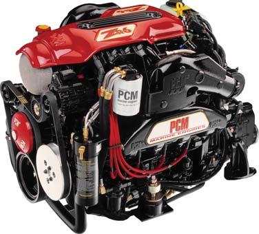


1 MARINE ILLUSTRATED PARTS MANUAL MODEL MP6.0L MY /04
2 This Page Was Intentially Left Blank
3 MODEL MP6.0L PARTS MANUAL - Contents: Symbols... 2 Maintenance Item Part Numbers... 3 Cylinder Block Assembly - Figure... 4 Cylinder Head Assembly / Front Cover - Figure Exhaust Manifold Assembly / Knock Sensors - Figure Intake Manifold Components - Figure Oil Pan and Oil Pump Assembly - Figure Throttle Body Assemblies and Related Components - Figure Remote Oil Filter Components (Standard Drive) - Figure Remote Oil Filter Components ( V - Drive) - Figure Fuel Control Cell (FCC) Components 03 (Standard Drive) - Figure Fuel Control Cell (FCC) Components 04 (Standard Drive) - Figure Fuel Control Cell (FCC) Components 03 ( V - Drive) - Figure Fuel Control Cell (FCC) Components 04 ( V - Drive) - Figure Heat Exchanger and Components - Figure Fresh Water Cooling System Components - Figure Raw Water Drain System Components - Figure Exhaust Manifold and Components - Figure Raw Water Cooling Pump - Figure Wiring Harness Assemblies and Senders - Figure ECM and Relays - Figure Accessory Drive System Components - Figure Starter Assembly Components - Figure Engine and Transmission Mounts - Figure Bellhousing Assembly - Figure Transmission and Related Parts (Standard Drive) - Figure Transmission and Related Parts ( V - Drive) - Figure TYPICAL VIEWS ARE SHOWN ENGINE ROTATION Engine Rotation is identifi ed as RH or LH with the engine model number. Rotation always is determined from the fl ywheel end looking toward the front of the engine. In some instances, propeller shaft rotation may be opposite to that of the engine. When ordering a replacement engine, production block or parts for the engine, be certain to check engine rotation. DO NOT rely on propeller rotation in order to determine engine rotation. LEFT-HAND ROTATION is STANDARD ROTATION. (Flywheel turns counterclockwise when viewed from fl ywheel end of the engine.) RIGHT-HAND ROTATION is OPPOSITE ROTATION. (Flywheel turns clockwise when viewed from fl ywheel end of the engine.)
4 MODEL MP6.0L PARTS MANUAL - 2 HOW TO READ THIS PARTS BOOK: ITEM PART NUMBER DESCRIPTION QUANTITY RB00005I Base Engine Assembly, 6.0L ITEM NUMBER - This number corresponds with the number in the exploded view on the facing page. 2 PART NUMBER - This is the designated part number for the particular component or assembly. 3 DESCRIPTION - This identifi es what the component or assembly is. 4 QUANTITY - This refers to the number of pieces used. ====================================================================== Symbols shown throughout parts list are defi ned here or on the bottom of the individual parts list page. AR = As Required OPT = Optional NSS = Not Serviced Separately NA = Not Available OS = Oversize US = Undersize TBD = To Be Determined NI = Not Illustrated ======================================================================
5 MODEL MP6.0L PARTS MANUAL - 3 REPLACEMENT PARTS: WARNING: Electrical, ignition and fuel system components on PCM Engines are designed and manufactured to comply with U.S. Coast Guard rules and regulations to minimize risks of fi re or explosion. Use of replacement electrical, ignition and fuel system components which do not comply with these rules and regulations could result in a fi re or explosion hazard and should be avoided. MAINTENANCE ITEM PART NUMBERS: Description Oil Filter Fuel Filter (FCC) Spark Plugs Spark Plug Wire Set Serpentine Drive Belt Raw Water Pump Impeller Kit Thermostat Part Number R07700 RP RP0300 RK2002 R RP06022 R MARINE TRANSMISSIONS: PCM Engines are equipped with PCM or Hurth Transmissions, standard or V -drive. If transmission parts are required, contact your dealer or closest PCM Parts Distributor for required parts. Parts manuals and overhaul manuals are available through PCM Distributors.
6 MODEL MP6.0L PARTS MANUAL - 4 CYLINDER BLOCK ASSEMBLY - FIGURE PC60P_
7 MODEL MP6.0L PARTS MANUAL - 5 CYLINDER BLOCK ASSEMBLY - FIGURE ITEM PART NUMBER DESCRIPTION QUANTITY * RB0002 Base Engine Assembly TBD Bearing Set, camshaft 2 TBD Bearing Set, connecting rod (STD) 8 3 TBD Piston, (STD) 8 4 TBD Ring Set, piston (STD) 8 5 TBD Connecting Rod (STD) 8 6 TBD Bolt, connecting rod cap 6 7 TBD Bolt, rear engine cover 2 8 RA3806 Flywheel Assembly 9 R Bolt, fl ywheel attaching 6 0 R Seal, crankshaft rear oil TBD Cover, rear engine 2 TBD Gasket, rear engine cover 3 part of item #4 Reluctor Ring, crankshaft 4 TBD Crankshaft Assembly 5 TBD Bearing Set, crankshaft 6 TBD Cap, crankshaft bearing # and #5 2 7 TBD Bolt, crankshaft bearing cap side 0 8 TBD Cap, crankshaft bearing #2 - #4 3 9 TBD Stud, crankshaft bearing cap attaching 20 TBD Bolt, crankshaft bearing cap attaching 2 R06406 Balancer, crankshaft 22 TBD Bolt, crankshaft balancer 23 TBD Oil Pump Assembly 24 TBD Drive, oil pump 25 TBD Key, crankshaft 26 TBD Chain, timing 27 TBD Bolt, camshaft sprocket attaching 28 TBD Sprocket, camshaft 29 TBD Bolt, camshaft retainer attaching 3 30 TBD Retainer, camshaft 3 TBD Camshaft
8 MODEL MP6.0L PARTS MANUAL - 6 CYLINDER HEAD ASSEMBLY / FRONT COVER - FIGURE PC60P_
9 MODEL MP6.0L PARTS MANUAL - 7 CYLINDER HEAD ASSEMBLY / FRONT COVER - FIGURE 2 ITEM PART NUMBER DESCRIPTION QUANTITY TBD Hose, PCV valve 2 TBD Valve, positive crankcase ventilation (PCV) 3 TBD Grommet, PCV valve 4 TBD Rocker Arm, valve 6 5 TBD Bolt, valve rocker arm attaching 6 6 TBD Guide, valve rocker arm 2 7 TBD Valve Spring Assembly 6 8 TBD Retainer, valve stem Bolt, lifting eye attaching Lockwasher, lifting eye attaching bolt 4 R04202 Lifting Eye 2 2 TBD Cap, valve spring 6 3 TBD Seal, valve stem 6 4 TBD Rotator, valve 32 5 TBD Guide, valve stem 6 6 RP0300 Spark Plug 8 7 RK2002 Spark Plug Wire Set 8 R Engine Coolant Temperature (ECT) Sensor 9 TBD Valve, exhaust (STD) 8 20 TBD Valve, intake (STD) 8 2 TBD Bolt, valve lifter retainer attaching 8 22 TBD Retainer, valve lifter 8 23 RM0280 Gasket, front engine cover 24 TBD Cover, front engine 25 R Seal, front engine cover oil 26 RM028 Gasket, water circulating pump 2 27 RA Water Circulation Pump Assembly 28 TBD Bolt, water circulating pump attaching 4 29 RM0275 Gasket, thermostat housing 2 30 R Housing, thermostat Bolt, thermostat housing attaching Lockwasher, thermostat housing attaching Plug, thermostat housing 34 R Thermostat, (60 F) 35 R0905 Plate, thermostat retainer 36 RS355 Plug, water neck 37 R Water Neck 38 R Switch, coolant temperature 39 TBD Bolt, front engine cover attaching 8
10 MODEL MP6.0L PARTS MANUAL - 8 CYLINDER HEAD ASSEMBLY / FRONT COVER - FIGURE 2 (cont d) PC60P_
11 MODEL MP6.0L PARTS MANUAL - 9 CYLINDER HEAD ASSEMBLY / FRONT COVER - FIGURE 2 (cont d) ITEM PART NUMBER DESCRIPTION QUANTITY 40 TBD Lifter, valve 6 4 TBD Push Rod 6 42 RM0278 Gasket, Cylinder Head 2 43 R00306 Cylinder Head 2 44 TBD Bolt, cylinder head (short) 6 45 TBD Bolt, cylinder head (medium) 4 46 TBD Bolt, cylinder head (long) 4 47 TBD Cover, rocker (LH) 48 RM0282 Gasket, rocker cover 2 49 TBD Bolt, rocker cover attaching 8 50 TBD Tube, breather 5 TBD Tube, oil fi ll 52 R034038B Cap, oil fi ll tube 53 TBD Fitting, breather tube 54 TBD Cover, rocker (RH)
12 MODEL MP6.0L PARTS MANUAL - 0 EXHAUST MANIFOLD / KNOCK SENSORS - FIGURE PC60P_
13 EXHAUST MANIFOLD / KNOCK SENSORS - FIGURE 3 MODEL MP6.0L PARTS MANUAL - ITEM PART NUMBER DESCRIPTION QUANTITY TBD Bolt, coolant air bleed pipe attaching 2 2 TBD Pipe, coolant air bleed 3 TBD Harness, knock sensor 4 TBD Bolt, crankshaft position attaching 5 R Sensor, crankshaft position 6 TBD Bolt, valley cover attaching 0 7 R Sensor, knock 2 8 TBD Cover, valley 9 TBD Gasket, valley cover 0 TBD Seal, knock sensor oil 2 R Sensor, camshaft position 2 TBD Bolt, camshaft position attaching 3 R02906 Elbow, exhaust 2 4 RM0274 Gasket, exhaust elbow to manifold 2 5 R Manifold, exhaust 2 6 R03035 Stud, exhaust manifold attaching Lockwasher, exhaust manifold stud attaching Nut, exhaust manifold stud attaching 2 9 R Switch, exhaust temperature 2
14 MODEL MP6.0L PARTS MANUAL - 2 INTAKE MANIFOLD COMPONENTS - FIGURE PC60P_
15 INTAKE MANIFOLD COMPONENTS - FIGURE 4 MODEL MP6.0L PARTS MANUAL - 3 ITEM PART NUMBER DESCRIPTION QUANTITY R75055 Bolt, engine cover attaching 2 2 R Insert, engine cover 3 R Cover, engine 4 R703 Coil, ignition 8 5 R Bracket, ignition coil mounting 2 6 R Bracket, support 2 7 TBD Bolt, fuel rail attaching 4 8 RK2002 Spark Plug Wire Set 9 R Regulator, fuel pressure ( 03 Only) 0 R Sensor, manifold absolute pressure (MAP) TBD Seal, throttle body 2 R Plate, throttle body adapter 3 RM025 Gasket, throttle body 4 RA035036B Throttle Body Assembly 5 L0098 Nut, throttle body attaching 3 6 R Intake Manifold 7 RA Fuel Injector Assembly 8 8 R27097 Retainer, fuel injector 8 9 RS526 Bolt, coil bracket attaching Bolt, coil bracket attaching 2 NI Lockwasher, coil bracket attaching Bolt, ignition coil attaching 6 22 RM0277 Gasket Set, intake manifold 23 R4354 Decal, engine cover 2 24 R Fuel Rail, 6.0L, (right) 25 R Fuel Rail, 6.0L, w/regulator pocket (left) 25 R086004A Fuel Rail, 6.0L, w/o regulator pocket (left)
16 MODEL MP6.0L PARTS MANUAL - 4 OIL PAN and OIL PUMP ASSEMBLY - FIGURE PC60P_
17 OIL PAN and OIL PUMP ASSEMBLY - FIGURE 5 MODEL MP6.0L PARTS MANUAL - 5 ITEM PART NUMBER DESCRIPTION QUANTITY R04079 Tube, oil dipstick 2 R04080 Dipstick, oil level (0 to 4 degree) AR 2 R0408 Dipstick, oil level (2 degree) AR 3 RS0302 Bolt, oil dipstick tube attaching 4 R2705 Clamp, oil dipstick tube attaching 5 RS280 Lockwasher, oil dipstick tube attaching 6 RS028 Nut, oil dipstick tube attaching 7 TBD Bolt, engine rear cover attaching 8 R Seal, engine rear cover oil 9 TBD Cover, engine rear 0 R Tube, oil pickup RM0279 Gasket, oil pan 2 R Oil Pan 3 TBD Bolt, oil sending unit adapter attaching 2 4 R07907 Adapter, oil sending unit 5 TBD Gasket, oil sending unit adapter 6 TBD Bolt, oil pan attaching (long) 2 7 TBD Bolt, oil pan attaching (short) 2 8 TBD Nut, oil pickup tube attaching 9 TBD Bolt, oil pickup tube attaching 20 TBD Nut, windage tray attaching 0 2 TBD O-ring, oil pickup tube 22 R02027 Tray, windage 23 TBD Bolt, oil pump attaching 4 24 TBD Oil Pump Assembly 25 TBD Drive, oil pump
18 MODEL MP6.0L PARTS MANUAL - 6 THROTTLE BODY and RELATED COMPONENTS - FIGURE PC60P_
19 MODEL MP6.0L PARTS MANUAL - 7 THROTTLE BODY and RELATED COMPONENTS - FIGURE 6 ITEM PART NUMBER DESCRIPTION QUANTITY R45026 Arrestor, fl ame 2 RS3857 Clamp, fl ame arrestor 3 R Bracket, perfect pass 4 R08008 Throttle Arm, throttle body 5 RA035036B Throttle Body Assembly 6 R Valve, idle air control 7 TBD Screw, IAC valve attaching 2 8 TBD Screw, TP sensor attaching 2 9 R02004 Sensor, throttle position 0 R78003 Ball Joint Assembly, cable attaching RS2055 Locking Nut, cable clip mounting bolt 2 2 R090267A Throttle Bracket, intake 3 TBD Bolt, throttle cable brkt attaching 2 4 R Cable Clip, throttle attaching 5 RS522 Bolt, cable clip mounting 2 6 RS078 Nut, throttle arm attaching 2 7 RS025 Bolt, throttle arm attaching Lockwasher, bracket attaching 9 RS6503 Bolt, bracket attaching
20 MODEL MP6.0L PARTS MANUAL - 8 REMOTE OIL FILTER COMPONENTS (STANDARD DRIVE) - FIGURE PC60P_
21 MODEL MP6.0L PARTS MANUAL - 9 REMOTE OIL FILTER COMPONENTS (STANDARD DRIVE) - FIGURE 7 ITEM PART NUMBER DESCRIPTION QUANTITY Bolt, oil fi lter header mounting 3 2 RS279 Lockwasher, oil fi lter header mounting 3 3 R Oil Filter Header 4 R Bracket, oil fi lter header mounting 5 RS540 Nut, sender terminal 6 RS297 Lockwasher, sender terminal 7 R02000 Sender, oil pressure 8 R02445 Tee, sender attaching 9 R02005A Switch, oil pressure 0 R07907 Adapter, oil sending unit R O-ring, oil bypass adapter 2 R Adapter, oil bypass 3 R O-ring, oil bypass adapter attaching fi tting 4 R Nut, oil bypass adapter attaching 5 R02484 Fitting, 90 degree 6 RA04520D Hose Assembly, fi lter header to bypass adapter 7 RA04520D Hose Assembly, bypass adapter to fi lter header 8 R02448 Fitting, straight 9 R07700 Filter, oil 20 R Nipple, header fi lter adapter 2 R O-Ring, oil line 2
22 MODEL MP6.0L PARTS MANUAL - 20 REMOTE OIL FILTER COMPONENTS ( V - DRIVE) - FIGURE PC60P_
23 MODEL MP6.0L PARTS MANUAL - 2 REMOTE OIL FILTER COMPONENTS ( V - DRIVE) - FIGURE 8 ITEM PART NUMBER DESCRIPTION QUANTITY R Bracket, oil fi lter header mounting 2 R Oil Filter Header 3 R Nipple, header fi lter adapter 4 R07700 Filter, oil 5 RS279 Lockwasher, oil fi lter header mounting Bolt, oil fi lter header mounting 3 7 RA04520 Hose Assembly, bypass adapter to fi lter header 8 RA04520 Hose Assembly, fi lter header to bypass adapter 9 R02484 Fitting, 90 degree 2 0 R Fitting, oil bypass adapter attaching R O-ring, oil bypass adapter attaching fi tting 2 R Adapter, oil bypass 3 R O-ring, oil bypass adapter 4 R07907 Adapter, oil sending unit 5 R02005A Switch, oil pressure 6 R02445 Tee, sender attaching 7 R02000 Sender, oil pressure 8 RS297 Lockwasher, sender terminal 9 RS540 Nut, sender terminal 20 R O-Ring, oil line 2
24 MODEL MP6.0L PARTS MANUAL - 22 FUEL CONTROL CELL (FCC) COMPONENTS 2003 (STANDARD DRIVE) - FIGURE a PC60P_
25 MODEL MP6.0L PARTS MANUAL - 23 FUEL CONTROL CELL (FCC) COMPONENTS 2003 (STANDARD DRIVE) - FIGURE 9 ITEM PART NUMBER DESCRIPTION QUANTITY RA03503 Fitting, fuel pressure, Schrader valve NI R03404 Cap, schrader valve 2 R02463A Fitting, fuel line 3 R02475 Fitting, fuel line 3a RA Pump, high pressure fuel 4 R04724 O-ring, FCC sealing 5 RP Filter, FCC fuel (includes O-ring) 6 RA085090C Hose Assembly, FCC to fuel rail (inlet) 7 RA08509C Hose Assembly, fuel rail to FCC (return) Bolt, FCC mounting 3 9 R Bracket, FCC mounting 0 R Fitting, 90 degree RS52L Locking Nut, low-pressure fuel pump 3 2 R09642 Washer, fuel pump mounting 3 3 R094035A Grommet, mounting bracket 3 4 R Bracket, low-pressure fuel pump mounting 5 R0964 Washer, fuel pump mounting 3 6 R Fitting, 90 degree 7 RA08008 Fuel Pump, low-pressure 8 R02492 Fitting, 90 degree 9 RA085070A Hose Assembly, low-pressure pump to FCC 20 RA Fuel Control Cell Assembly NI R432 Decal, FCC operating instructions NI R434 Decal, Warning, fuel leaks 2 R02463 Fitting, 90 degree Bolt, FCC mounting bracket 2 23 RS7070 Lockwasher, FCC mounting bracket Lockwasher, bracket attaching Bolt, bracket attaching
26 MODEL MP6.0L PARTS MANUAL - 24 FUEL CONTROL CELL (FCC) COMPONENTS 2004 (STANDARD DRIVE) - FIGURE PC60P_008a
27 MODEL MP6.0L PARTS MANUAL - 25 FUEL CONTROL CELL (FCC) COMPONENTS 2004 (STANDARD DRIVE) - FIGURE 0 ITEM PART NUMBER DESCRIPTION QUANTITY R02424 Fitting, fuel line 2 R Regulator, fuel pressure ( 04 Only) 3 RA Pump, high pressure fuel 4 R04724 O-ring, FCC sealing 5 RP Filter, FCC fuel (includes O-ring) 6 RA085090C Hose Assembly, FCC to fuel rail (inlet) Bolt, FCC mounting 3 8 R Bracket, FCC mounting 9 R Fitting, 90 degree 0 RS52L Locking Nut, low-pressure fuel pump 3 R09642 Washer, fuel pump mounting 3 2 R094035A Grommet, mounting bracket 3 3 R Bracket, low-pressure fuel pump mounting 4 R0964 Washer, fuel pump mounting 3 5 R Fitting, 90 degree 6 RA08008 Fuel Pump, low-pressure 7 R02492 Fitting, 90 degree 8 RA085070A Hose Assembly, low-pressure pump to FCC 9 RA Fuel Control Cell Assembly NI R432 Decal, FCC operating instructions NI R434 Decal, Warning, fuel leaks 20 R02463 Fitting, 90 degree Bolt, FCC mounting bracket 2 22 RS7070 Lockwasher, FCC mounting bracket Lockwasher, bracket attaching Bolt, bracket attaching
28 MODEL MP6.0L PARTS MANUAL - 26 FUEL CONTROL CELL (FCC) COMPONENTS 2003 ( V - DRIVE) - FIGURE 2 3 3a PC60P_
29 MODEL MP6.0L PARTS MANUAL - 27 FUEL CONTROL CELL (FCC) COMPONENTS 2003 ( V - DRIVE) - FIGURE ITEM PART NUMBER DESCRIPTION QUANTITY RA03503 Fitting, fuel pressure, schrader valve NI R03404 Cap, schrader valve 2 R02463A Fitting, fuel line 3 R02475 Fitting, fuel line 3a RA Pump, high pressure fuel ( 03 Only) 4 R04724 O-ring, FCC sealing 5 RP Filter, FCC fuel (includes O-ring) 6 RA085090B Hose Assembly, FCC to fuel rail (inlet) 7 RA08509B Hose Assembly, fuel rail to FCC (return) Bolt, FCC mounting 3 9 R Bracket, FCC mounting 0 RS7070 Lockwasher, FCC mounting bracket Bolt, FCC mounting bracket 2 2 R Fitting, 90 degree 3 R02463 Fitting, 90 degree 2 4 RA Fuel Control Cell Assembly NI R432 Decal, FCC operating instructions NI R434 Decal, Warning, fuel leaks 5 RA08507B Hose Assembly, low-pressure pump to FCC 6 RS52L Locking Nut, low-pressure fuel pump 3 7 R09642 Washer, fuel pump mounting 3 8 R Grommet, mounting bracket 3 9 R Bracket, low-pressure fuel pump mounting 20 R0964 Washer, fuel pump mounting 3 2 R Fitting, 90 degree 22 RA08008 Fuel Pump, low-pressure Lockwasher, bracket attaching Bolt, bracket attaching
30 MODEL MP6.0L PARTS MANUAL - 28 FUEL CONTROL CELL (FCC) COMPONENTS 2004 ( V - DRIVE) - FIGURE PC60P_03a
31 MODEL MP6.0L PARTS MANUAL - 29 FUEL CONTROL CELL (FCC) COMPONENTS 2004 ( V - DRIVE) - FIGURE 2 ITEM PART NUMBER DESCRIPTION QUANTITY R02424 Fitting, fuel line 2 R Regulator, fuel pressure ( 04 Only) 3 RA Pump, high pressure fuel ( 04 Only) 4 R04724 O-ring, FCC sealing 5 RP Filter, FCC fuel (includes O-ring) 6 RA085090B Hose Assembly, FCC to fuel rail (inlet) Bolt, FCC mounting 3 8 R Bracket, FCC mounting 9 RS7070 Lockwasher, FCC mounting bracket Bolt, FCC mounting bracket 2 R Fitting, 90 degree 2 R02463 Fitting, 90 degree 2 3 RA Fuel Control Cell Assembly NI R432 Decal, FCC operating instructions NI R434 Decal, Warning, fuel leaks 4 RA08507B Hose Assembly, low-pressure pump to FCC 5 RS52L Locking Nut, low-pressure fuel pump 3 6 R09642 Washer, fuel pump mounting 3 7 R Grommet, mounting bracket 3 8 R Bracket, low-pressure fuel pump mounting 9 R0964 Washer, fuel pump mounting 3 20 R Fitting, 90 degree 2 RA08008 Fuel Pump, low-pressure Lockwasher, bracket attaching Bolt, bracket attaching
32 MODEL MP6.0L PARTS MANUAL - 30 HEAT EXCHANGER and COMPONENTS - FIGURE PC60P_
33 HEAT EXCHANGER and COMPONENTS - FIGURE 3 MODEL MP6.0L PARTS MANUAL - 3 ITEM PART NUMBER DESCRIPTION QUANTITY R Cap, degas bottle 2 R4600 Bottle, degas NI R4352 Decal, 6.0L specifi cation NI R4353 Decal, coolant fi ll 3 RS3872 Clamp, hose 2 4 R04553 Hose, degas bottle to heat exchanger 5 R68008 Anode, sacrifi cial zinc AR 6 RS078 Nut, ground wire stud 7 R003 Wire, grounding 8 RA47047 Heat Exchanger Assembly 9 R End Cap Kit, exchanger AR 0 R Isolator, rubber 2 R Bracket, heat exchanger 2 RS0304 Bolt, heat exchanger bracket attaching 2 3 RS2380 Lockwasher, mounting bolt 2 4 RS3857 Clamp, exchanger mounting 2 NI R4355 Decal, Protective Anode NI R4362 Decal, 6.0 Emission MY 03 NI R Decal, 6.0 Emission MY 04 NI R4358 Decal, Ultra Low Emission
34 MODEL MP6.0L PARTS MANUAL - 32 FRESH WATER COOLING SYSTEM COMPONENTS - FIGURE PC60P_
35 MODEL MP6.0L PARTS MANUAL - 33 FRESH WATER COOLING SYSTEM COMPONENTS - FIGURE 4 ITEM PART NUMBER DESCRIPTION QUANTITY R0455 Hose, exchanger to exhaust manifold (Starboard STD) 2 RS3872 Clamp, hose 2 3 R04553 Hose, degas bottle to heat exchanger 4 R Cap, degas bottle 5 R4600 Bottle, degas 6 R27087 Clamp, hose (5/8 - degas bottle) 7 R04532 Hose, coolant air bleed to bottle 8 RS385 Clamp, hose ( ) 4 9 R04549 Hose, circ. pump to heat exchanger 0 RS3868 Clamp, hose ( /2 ) 2 R04548 Hose, exchanger to thermostat housing 2 R04550 Hose, exchanger to exhaust manifold (Port STD) 3 R024006A Fitting, 90 degree 4 R4704 Cooler, transmission oil Plug, manifold 2 6 TBD Tube, coolant air bleed 7 RM028 Gasket, water pump to engine block 2 8 RA Water Pump Assembly 9 RA Raw Water Pump 20 R04559 Hose, oil cooler to raw water pump (level installation with.23: transmission) 20 R04552 Hose, oil cooler to raw water pump (angled installation with.0: transmission) 2 R04547 Hose, raw water pump to exchanger 22 RM0275 Gasket, thermostat housing 2 23 R Thermostat Housing 24 R0905 Plate, thermostat retainer 25 R Thermostat, (60 degree) 26 R Water Neck 27 R04553 Hose, coolant bypass fi tting (3/4 bulk) 28 R02420 Bypass, coolant 29 R Hose, coolant bypass fi tting (5/8 bulk) 30 R Fitting, manifold straight 3 RS3858 Clamp, hose ( /4 ) 6 32 R27087G Clamp, hose ( /6 oetiker) 2 33 R27087F Clamp, hose ( oetiker) 2 34 R27084 Clamp, hose (vent tube)
36 MODEL MP6.0L PARTS MANUAL - 34 OPTIONAL DRAIN KIT COMPONENTS - FIGURE DRAIN = Drain Kit The drain kit does not ensure that all of the water will drain out of the system. Engine angle, routing of drain hose, and restricted drain fittings are some things that could prevent all of the water from draining completely.
37 OPTIONAL DRAIN KIT COMPONENTS - FIGURE 5 MODEL MP6.0L PARTS MANUAL - 35 ITEM PART NUMBER DESCRIPTION QUANTITY R02428 Fitting, straight 4 2 R02425 Tee, hose 2 3 RS3557 Plug, drain 4 R02426 Fitting, 4-way RW drain NS R27087G Clamp, hose ( /6 oetiker) 0 NS R27087F Clamp, hose ( oetiker) 2
38 MODEL MP6.0L PARTS MANUAL - 36 EXHAUST MANIFOLD and COMPONENTS - FIGURE PC60P_
39 EXHAUST MANIFOLD and COMPONENTS - FIGURE 6 MODEL MP6.0L PARTS MANUAL - 37 ITEM PART NUMBER DESCRIPTION QUANTITY RS527 Nut, exhaust elbow attaching 8 2 RS279 Lockwasher, exhaust elbow attaching 8 3 RM0274 Gasket, manifold to exhaust elbow 2 4 R03036 Stud, exhaust elbow attaching (short) 4 4 R03039 Stud, exhaust elbow attaching w/4 riser (short) AR 5 R Exhaust Manifold Assembly 2 6 R03035 Stud, manifold to cylinder head attaching 2 7 RS279 Lockwasher, manifold to cylinder head attaching 2 8 RS7026 Nut, manifold to cylinder head attaching 2 9 RM0276 Gasket, manifold to cylinder head 2 0 R02906 Exhaust Elbow Assembly 2 R03037 Stud, exhaust elbow attaching (long) 4 R03040 Stud, exhaust elbow attaching w/4 riser (long) AR 2 R Switch, exhaust temperature 2 3 R09644 Retainer, spark plug wire clip Washer, retainer attaching 2 5 RS0280 Bolt, retainer attaching 2 6 TBD Bolt, bracket attaching Lockwasher, bracket attaching Bolt, bracket attaching 4 9 R Bracket, manifold support 2 20 R43002F Decal, exhaust manifold, 6.0L 2 *NOTE: See Fresh Water Cooling section for parts used on Fresh Water Cooled engines.
40 MODEL MP6.0L PARTS MANUAL - 38 RAW WATER COOLING PUMP - FIGURE PC60P_
41 RAW WATER COOLING PUMP - FIGURE 7 MODEL MP6.0L PARTS MANUAL - 39 ITEM PART NUMBER DESCRIPTION QUANTITY TBD Bolt, bearing housing attaching 3 2 TBD Lockwasher, bearing housing attaching bolt 3 3 R O-ring, bearing housing attaching bolt 3 4 R O-ring, bearing housing attaching 5 RP06022 Impeller 6 R Housing, raw water pump 7 RA3407 Bearing Housing Assembly 8 RA Raw Water Pump Assembly
42 MODEL MP6.0L PARTS MANUAL - 40 WIRING HARNESS ASSEMBLIES and SENDERS - FIGURE PC60P_
43 MODEL MP6.0L PARTS MANUAL - 4 WIRING HARNESS ASSEMBLIES and SENDERS - FIGURE 8 ITEM PART NUMBER DESCRIPTION QUANTITY RS540 Nut, sender terminal 2 RS297 Lockwasher, sender terminal 3 RS2746 Washer, sender terminal 4 R Sender, temperature 5 R02009 Sensor, engine coolant temperature (ECT) 6 RA2076C Engine Wiring Harness Assembly ( 02-04) (MUST be used with relay, p/n R300A) 7 R09642 Washer, main harness attaching 4 8 RS55 Screw, main harness attaching 4 9 RS540 Nut, sender terminal 0 RS297 Lockwasher, sender terminal R02000 Sender, oil pressure 2 R02445 Tee, sender attaching 3 R07907 Adapter, oil sending unit 4 R02005A Switch, oil pressure 5 TBD Harness, ignition coil 2 6 R2078 Harness, FCC ( V - Drive) AR
44 MODEL MP6.0L PARTS MANUAL - 42 ECM and RELAYS - FIGURE a a A / 6A PC60P_
45 ECM and RELAYS - FIGURE 9 MODEL MP6.0L PARTS MANUAL - 43 ITEM PART NUMBER DESCRIPTION QUANTITY R53006C Circuit Breaker Assembly (60 amp) 2 RS5084 Bolt, circuit breaker mounting Bolt, circuit breaker bracket attaching 2 4 R Bracket, circuit breaker mounting NI Decal, main circuit breaker 5 RS0302 Bolt, oil dipstick tube attaching 6 R3002 Relay, fuel pump, ignition, starter 3 (s/n thru 44502) 6A R300A Relay, fuel pump, ignition, starter 3 (s/n thru present) 7 R609K Engine Control Module (MEFI 4) ( 03 Only) 7 R602 Engine Control Module (MEFI 4B) ( 04 Only) Bolt, ECM attaching 3 9 R2604 Cover, fuse holder 0 R5307B Fuses, 20 amp 3 RS0304 Bolt, bracket attaching 2 2 RS280 Lockwasher, bracket attaching bolt 2 3 RS028 Nut, oil dipstick tube attaching 4 RS280 Lockwasher, oil dipstick tube attaching 5 R2705 Clamp, oil dipstick tube attaching 6 R Bracket, ECM/relay mounting
46 MODEL MP6.0L PARTS MANUAL - 44 ACCESSORY DRIVE SYSTEM COMPONENTS - FIGURE 20 Belt Tensioner Alternator Idler Circulation Pump Raw Water Pump Crankshaft Pulley A PC60P_
47 MODEL MP6.0L PARTS MANUAL - 45 ACCESSORY DRIVE SYSTEM COMPONENTS - FIGURE 20 ITEM PART NUMBER DESCRIPTION QUANTITY R Belt, serpentine drive 2 part of item #5 Bolt, tensioner pulley attaching 3 part of item #5 Washer, tensioner pulley attaching bolt 4 part of item #5 Pulley, tensioner 5 RA Tensioner, belt 6 RS653 Bolt, idler pulley attaching 7 RS279 Lockwasher, idler pulley attaching bolt Washer, idler pulley attaching bolt (small) 9 R09645 Washer, idler pulley attaching bolt (large) 0 R Pulley, idler R Bracket, idler pulley mounting / alternator Lockwasher, idler pulley bracket attaching bolt Bolt, idler pulley bracket attaching Bolt, alternator mounting 5 RA Raw Water Pump Assembly Bolt, raw water pump mounting 2 7 R Pulley, raw water pump Flat Washer, raw water pump pulley attaching Lockwasher, raw water pump pulley attaching bolt Bolt, raw water pump pulley attaching 3 2 R06406 Balancer, crankshaft 22 TBD Bolt, crankshaft balancer 23 TBD Bolt, water circulation pump attaching 4 24 TBD Bolt, belt tensioner mounting 3 25 RA097007C Alternator Assembly 26 R Pulley, alternator (70 amp) Flatwasher, alternator mounting Lockwasher, alternator mounting Bolt, alternator mounting 30 R4347 Decal, belt routing
48 MODEL MP6.0L PARTS MANUAL - 46 STARTER ASSEMBLY COMPONENTS - FIGURE PC60P_
49 STARTER ASSEMBLY COMPONENTS - FIGURE 2 MODEL MP6.0L PARTS MANUAL - 47 ITEM PART NUMBER DESCRIPTION QUANTITY RS708 Nut, solenoid terminal 2 RS7080 Lockwasher, solenoid terminal 3 RU0050A Solenoid, starter 4 R Bolt, starter mounting 2 5 RA2209 Starter Motor Assembly Lockwasher, solenoid terminal 2 7 RS7036 Nut, solenoid terminal 2
50 MODEL MP6.0L PARTS MANUAL - 48 ENGINE and TRANSMISSION MOUNTS - FIGURE 22 Engine Mount Group Front Mount Engine Mount Group Rear Mount PC60P_
51 ENGINE and TRANSMISSION MOUNTS - FIGURE 22 MODEL MP6.0L PARTS MANUAL - 49 ITEM PART NUMBER DESCRIPTION QUANTITY R Bolt, trunnion clamp Lockwasher, engine mount attaching bolt Bolt, engine mount attaching 8 4 R Mount, engine front 2 5 RS28 Lockwasher, trunnion clamp bolt 2 6 RS529 Nut, trunnion clamp bolt 2 7 RS075 Nut, adjustment and lock 4 8 RS286 Lockwasher, adjusting nut 2 9 R0900 Trunnion 2 0 RC0900 Trunnion Assembly RA09206 Trunnion Assembly 2 RA0920 Trunnion Assembly, tall (.23: STD / V-drive) 2 Used with item #7 - R09045 mount 2 RA0920A Trunnion Assembly, tall (.23: STD / V-drive) 2 Used with item #6 - R mount 2 RA09003 Trunnion Assembly, short (.0: STD) 2 Used with item #7 - R09045 mount 2 RA09006 Trunnion Assembly, short (.0: STD) 2 Used with item #6 - R mount 3 R09003 Trunnion, 2.5 (use with R09045) 2 3 R09006 Trunnion, 2.25 (use with R090205) 2 4 RS0329 Bolt, rear mount attaching (R090205) 4 4 RS0328 Bolt, rear mount attaching (R09045) 4 5 RS28 Lockwasher, rear mount attaching bolt 4 6 R Mount, rear 7 R09045 Mount, rear 8 R Mount, engine front (port).23: 8 R Mount, engine front (starboard).23: 8 R Mount, engine front (port).0: 8 R Mount, engine front (starboard).0: NI Lockwasher, engine mount attaching bolt 6 NI Bolt, engine mount attaching, upper 4 NI Bolt, engine mount attaching, lower 2
52 MODEL MP6.0L PARTS MANUAL - 50 BELL HOUSING ASSEMBLY - FIGURE a PC60P_
53 BELL HOUSING ASSEMBLY - FIGURE 23 MODEL MP6.0L PARTS MANUAL - 5 ITEM PART NUMBER DESCRIPTION QUANTITY RA5706 Transmission Assembly, (:) AR a R Adapter, V-Drive AR 2 RS28 Lockwasher, transmission attaching bolt 4 3 RS0334 Bolt, transmission attaching 4 4 RA5707 Transmission Assembly, (.23:) AR 5 R4006 Plate, damper (PCM Transmissions) 5 R4008 Plate, damper (Hurth Transmission/2-speed) 6 RS7070 Lockwasher, damper plate attaching bolt Bolt, damper plate attaching 6 8 R090A Cover, dust, (stbd) (use w/top mount starter) 8 R090 Cover, dust (stbd) (use w/bottom mount starter) 9 R0902 Cover, dust (port) 0 RS078 Nut, dust cover attaching 2 RS6503 Bolt, dust cover attaching 2 2 RS0256 Bolt, dust cover attaching 2 3 R03034 Stud, bellhousing attaching 2 4 RS7070 Lockwasher, bellhousing attaching Nut, bellhousing attaching 2 6 RS6556 Bolt, bellhousing attaching 2 7 RS7070 Lockwasher, bellhousing attaching 2 8 R4204A Bellhousing Lockwasher, dust cover attaching 2 NI R0900 Cover, dust, top mount starter (used w/r090) NI RS0327 Bolt, dust cover attaching 2 NI RS28 Lockwasher, dust cover attaching 2
54 MODEL MP6.0L PARTS MANUAL - 52 TRANSMISSION AND RELATED COMPONENTS (STANDARD DRIVE) - FIGURE A - FRONT MOUNT SHIFT BRACKET A PC60P_
55 MODEL MP6.0L PARTS MANUAL - 53 TRANSMISSION AND RELATED COMPONENTS (STANDARD DRIVE) - FIGURE 24 ITEM PART NUMBER DESCRIPTION QUANTITY R Cable Clip, single cable 2 RS522 Bolt, cable clip attaching 2 3 R09043A Bracket, shift 4 RS2055 Nut, cable clip attaching bolt 2 5 R02400 Fitting, 90 degree 6 R Fitting, 45 degree 7 RA5707 Transmission,.23: 7 RA5706 Transmission,.0: AR 8 RA045007B Hose Assembly, cooler to transmission 9 R4704 Transmission Cooler Assembly 0 R02400 Fitting, 90 degree 2 RA045007T Hose Assembly, transmission to cooler
56 MODEL MP6.0L PARTS MANUAL - 54 TRANSMISSION AND RELATED COMPONENTS (.0: V - DRIVE) - FIGURE PCB57036
57 MODEL MP6.0L PARTS MANUAL - 55 TRANSMISSION AND RELATED COMPONENTS (.0: V - DRIVE) - FIGURE 25 ITEM PART NUMBER DESCRIPTION QUANTITY R09000 Bracket, oil cooler mounting 2 R4704 Cooler, oil, transmission 3 R02400 Fitting, 90 degree 4 R02400 Fitting, 90 degree 5 RA5706 Transmission,.0:, (w/r Adapter) 6 RA045007B Hose Assembly, cooler to transmission 2 7 RA045007K Hose Assembly, transmission to cooler 8 R02400 Fitting, 90 degree 2
MARINE ILLUSTRATED PARTS MANUAL MODEL MP6.0L
 MARINE ILLUSTRATED PARTS MANUAL MODEL MP6.0L L510014 12/02 This Page Was Intentially Left Blank MODEL MP6.0L PARTS MANUAL - 1 Contents: Symbols... 2 Maintenance Item Part Numbers... 3 Cylinder Block Assembly
MARINE ILLUSTRATED PARTS MANUAL
 MARINE ILLUSTRATED PARTS MANUAL MODEL MP454 XLi SERIAL NUMBER 101810 THRU 103880 MODEL MP7.4L SERIAL NUMBER 103538 AND ABOVE L510008 10/01 This Page Was Intentially Left Blank Contents: MODEL MP7.4L PARTS
MARINE ILLUSTRATED PARTS MANUAL MODEL MP6.0L MY
 MARINE ILLUSTRATED PARTS MANUAL MODEL MP6.0L 2004-2005 MY 05/07 This Page Was Intentially Left Blank MODEL MP6.0L PARTS MANUAL - 1 Contents: Symbols... 2 Maintenance Item Part Numbers... 3 Cylinder Block
MARINE ILLUSTRATED PARTS MANUAL
 MARINE ILLUSTRATED PARTS MANUAL MODEL MP 6.0L SN 48607 thru 48xxxx L007-08 08/08 This Page Was Intentially Left Blank MODEL MP6.0L PARTS MANUAL - Contents: Symbols... Maintenance Item Part Numbers... Cylinder
MARINE ILLUSTRATED PARTS MANUAL MODEL MP6.0L 2006 MY
 MARINE ILLUSTRATED PARTS MANUAL MODEL MP6.0L 2006 MY L1001-06 0/07 This Page Was Intentially Left Blank MODEL MP6.0L PARTS MANUAL - 1 Contents: Symbols... 2 Maintenance Item Part Numbers... 3 Cylinder
MARINE ILLUSTRATED PARTS MANUAL
 MARINE ILLUSTRATED PARTS MANUAL MODEL MP6.0L SN 670001 thru 60367 L1001-07 0/0 This Page Was Intentially Left Blank MODEL MP6.0L PARTS MANUAL - 1 Contents: Symbols... 2 Maintenance Item Part Numbers...
MARINE ILLUSTRATED PARTS MANUAL MODEL MP5.0/5.7L MY
 MARINE ILLUSTRATED PARTS MANUAL MODEL MP5.0/5.L 00-005 MY 05/0 This Page Was Intentially Left Blank MODEL MP5.0/5.L PARTS MANUAL - Contents: Symbols... Maintenance Item Part Numbers... Cylinder Block Assembly
MARINE ILLUSTRATED PARTS MANUAL MODEL MP8.1L 2006 MY
 MARINE ILLUSTRATED PARTS MANUAL MODEL MP8.L 006 MY L50009-06 0/07 This Page Was Intentially Left Blank MODEL MP8.L PARTS MANUAL - Contents: Symbols... Gasket and Decal Kit Numbers... 3 Maintenance Item
MARINE ILLUSTRATED PARTS MANUAL MODEL MP5.0/5.7L 2006 MY
 MARINE ILLUSTRATED PARTS MANUAL MODEL MP5.0/5.L 006 MY L500-06 05/0 This Page Was Intentially Left Blank MODEL MP5.0/5.L PARTS MANUAL - Contents: Symbols... Maintenance Item Part Numbers... Cylinder Block
MARINE ILLUSTRATED PARTS MANUAL MODEL MP8.1L 2007 MY
 MARINE ILLUSTRATED PARTS MANUAL MODEL MP8.L 007 MY L50009-07A 0/07 This Page Was Intentially Left Blank Contents: MODEL MP8.L PARTS MANUAL - Symbols... Maintenance Item Part Numbers... 3 Cylinder Block
2004 Fresh Water Cooling Installation Instructions - V-Drive Kit RK147050A
 2004 Fresh Water Cooling Installation Instructions - V-Drive Kit This Page Was Intentially Left Blank TABLE OF CONTENTS 1 - FWC Kit Installation Instructions - V-Drive... Table of Contents...... 1 Installation
5.7L ENGINE PARTS BOOK. Not for. Reproduction
 5.7L ENGINE PARTS BOOK Engine Model: Engine Family: PSI, Industrial Engine Spec N.: 39004120-39004248 Parts Book Revision: December, 2015 TABLE OF CONTENTS SECTION PAGE CYLINDER BLOCK... 3-5 CYLINDER HEAD...
FORD - Cyl Block and Related Parts
 FORD - Cyl Block and Related Parts Ref Description Qty All 302 Qty 351 Qty 351-HP 1 BLOCK ASSEMBLY 1 59-4046 1 59-4047 1 59-4047 2 PLUG - 1½ CUP - BRASS 6 59-4048 6 59-4048 6 59-4048 3 PLUG - OIL PASSAGE
E70PL4EEC 1999 : CAMSHAFT [1/23] Page 1 of 49
![E70PL4EEC 1999 : CAMSHAFT [1/23] Page 1 of 49](/thumbs/96/129257940.jpg "E70PL4EEC 1999 : CAMSHAFT [1/23] Page 1 of 49") E70PL4EEC 1999 : CAMSHAFT [1/23] Page 1 of 49 E70PL4EEC 1999 : CAMSHAFT [1/23] 1 5030657 1 CAMSHAFT 2 5030658 1 PLATE, Camshaft thrust 3 5030549 1 SEAL, Camshaft 4 5030989 2 BOLT, Plate 5 5030663 8 ARM,
E70PL4EEC 1999 : CAMSHAFT [1/23] Page 1 of 49 E70PL4EEC 1999 : CAMSHAFT [1/23] 1 5030657 1 CAMSHAFT 2 5030658 1 PLATE, Camshaft thrust 3 5030549 1 SEAL, Camshaft 4 5030989 2 BOLT, Plate 5 5030663 8 ARM,
3.0L (181 CID) PARTS MANUAL
 PARTS MANUAL") 3.0L (181 CID) PARTS MANUAL 17506 Marine Power Industrial Park Ponchatoula, LA 70454 Parts Direct Line: (985) 386-2081 Parts Direct Fax: (504) 386-0076 TL30L-0600 HOW TO USE THIS BOOK This 181 CID 3.0
3.0L (181 CID) PARTS MANUAL 17506 Marine Power Industrial Park Ponchatoula, LA 70454 Parts Direct Line: (985) 386-2081 Parts Direct Fax: (504) 386-0076 TL30L-0600 HOW TO USE THIS BOOK This 181 CID 3.0
E50PL4SSC 4-Stroke, Elec Start, TNT, 20 IN. shaft 2000 : CAMSHAFT & TIMING [1/21] Page 1 of 44
![E50PL4SSC 4-Stroke, Elec Start, TNT, 20 IN. shaft 2000 : CAMSHAFT & TIMING [1/21] Page 1 of 44](/thumbs/96/129257785.jpg "E50PL4SSC 4-Stroke, Elec Start, TNT, 20 IN. shaft 2000 : CAMSHAFT & TIMING [1/21] Page 1 of 44") E50PL4SSC 4-Stroke, Elec Start, TNT, 20 IN. shaft 2000 : CAMSHAFT & TIMING [1/21] Page 1 of 44 E50PL4SSC 4-Stroke, Elec Start, TNT, 20 IN. shaft 2000 : CAMSHAFT & TIMING [1/21] 1 5031326 1 CAMSHAFT, Intake
E50PL4SSC 4-Stroke, Elec Start, TNT, 20 IN. shaft 2000 : CAMSHAFT & TIMING [1/21] Page 1 of 44 E50PL4SSC 4-Stroke, Elec Start, TNT, 20 IN. shaft 2000 : CAMSHAFT & TIMING [1/21] 1 5031326 1 CAMSHAFT, Intake
DISASSEMBLED VIEWS. Disassembled Views. Engine Covers and Component Assemblies (1 of 2) (LF1, LFW or LFX)
 (LF1, LFW or LFX)") 2012 Cadillac CTS Wagon AWD V6-3.0L Vehicle > Engine, Cooling and Exhaust > Engine > Locations > Components DISASSEMBLED VIEWS Disassembled Views Engine Covers and Component Assemblies (1 of 2) (LF1, LFW
2012 Cadillac CTS Wagon AWD V6-3.0L Vehicle > Engine, Cooling and Exhaust > Engine > Locations > Components DISASSEMBLED VIEWS Disassembled Views Engine Covers and Component Assemblies (1 of 2) (LF1, LFW
COMPONENT LOCATOR > DISASSEMBLED VIEWS
 Page 1 of 45 2006 Pontiac Grand Prix 3.8L Eng Base Service Manual: ENGINE MECHANICAL - 3.8L COMPONENT LOCATOR > DISASSEMBLED VIEWS Fig 1: Engine Block Component Views Callout Component Name 100 Engine
DESCRIPTION AND OPERATION
 303-01B-10 Engine 3.0L 303-01B-10 DESCRIPTION AND OPERATION Upper Engine Components G72932 en 303-01B-11 Engine 3.0L 303-01B-11 DESCRIPTION AND OPERATION (Continued) Item Part Number Description 1 9H589
PARTIAL ENGINE ASSY (2TR FE)
") COMPONENTS 147 1421Z01 Clip Hood Subassy x9 Radiator Support to Frame Seal LH 30 (306, 22) 30 (306, 22) Fan and Generator V Belt 5.0 (51, 44 in. lbf) Fan Shroud Fan Pulley Fan w/ Fluid Coupling PRE RUNNER
COMPONENTS 147 1421Z01 Clip Hood Subassy x9 Radiator Support to Frame Seal LH 30 (306, 22) 30 (306, 22) Fan and Generator V Belt 5.0 (51, 44 in. lbf) Fan Shroud Fan Pulley Fan w/ Fluid Coupling PRE RUNNER
Fastener Tightening Specifications Specification
 2008 G6 Applies to: 3.5L Report a problem with this article Fastener Tightening s A/C Compressor Bracket Bolt Camshaft Position Actuator Assembly Bolt 16 Y 12 lb ft Camshaft Position Actuator Magnet Bolt
Air Intake/Filtration
 Air Intake/Filtration Air Intake/Filtration Ref # Part Description Qty 25 048 -S CLEANER, AIR-CANISTER (includes 2-8) 2 25 096 06-S COVER ASSMBLY,AIR CLEANER (includes 3,4) 3 24 462 07-S VALVE, DUST EJECTOR
Lower Intake Manifold Replacement
 Lower Intake Manifold Replacement Removal Procedure 1. Turn OFF all the lamps and the accessories. 2. Ensure the ignition switch is in the OFF position. 3. Disconnect the negative battery cable from the
Appendix 3 Exploded Views and Parts Lists
 Engine, Alternator Drive and Starter Assembly Drawing No. 0D5057-A 40 Generac Power Systems, Inc. Engine, Alternator Drive and Starter Assembly Drawing No. 0D5057-A 1 0C5598 1 BEARING CARRIER, FRONT 2
Illustrated Parts List MODEL Reproduction. Not for. 48,000 Watt Home Generator System
 Illustrated Parts List MODEL 076035-0 48,000 Watt Home Generator System Rev. A 4/14/2011 Table Of Contents PRODUCT COMPONENTS Main Unit... 4 Alternator... 6 Control Panel... 7 Enclosure... 8 Engine -
0G4969PMNL. 4.2 liter. Ford GAS ENGINE PARTS MANUAL
 0G4969PMNL 4.2 liter GAS Ford ENGINE PARTS MANUAL 4.2L Diesel Engine Table of Contents Quick Reference Guide... 1 Cylinder Block And Related Parts... 2 Timing Cover... 3 Cylinder Head... 4 Camshaft...
Service Parts 4CCFOZ 4/6.5EFOZ 5CCOZ 5/8EOZ. Marine Generator Sets. Models: TP /05c. Specification Series 126
 Service Parts Marine Generator Sets Models: 4CCFOZ 4/6.5EFOZ 5CCOZ 5/8EOZ Specification Series 126 TP-5616 9/05c Description Page Introduction... 3 Numbering System Significance... 3 Illustrations... 3
Parts Book. VGT series engine
 Parts Book VGT series engine Rev 2.2 AUG 2017 1 Dear customer In this catalog you will find all the components that your Marinediesel VGT-engine is constructed of. We have listed a couple of tips that
Carrier Transicold Diesel Engine CT4-91-TV (V1505) Service Parts List Rev A
 Service Parts List Rev A") Carrier Transicold Diesel Engine CT--TV (V0) Service Parts List -0 Rev A Service Parts List DIESEL ENGINE CT--TV (V0) CONTENTS INTRODUCTION... REPLACEMENT ENGINE PART NO.... ORDERING INSTRUCTIONS... GENERAL
Carrier Transicold Diesel Engine CT--TV (V0) Service Parts List -0 Rev A Service Parts List DIESEL ENGINE CT--TV (V0) CONTENTS INTRODUCTION... REPLACEMENT ENGINE PART NO.... ORDERING INSTRUCTIONS... GENERAL
P984 For Models: M984K, ML984, L984, M30C, M984W and M33CW OPERATOR S MANUAL. Marine Generators Marine Diesel Engines Land-Based Generators
 P984 For Models: M984K, ML984, L984, M30C, M984W and M33CW OPERATOR S MANUAL Marine Generators Marine Diesel Engines Land-Based Generators CALIFORNIA Proposition 65 Warning: Diesel engine exhaust and some
MPI PARTS MANUAL
 454 502 7.4 MPI PARTS MANUAL 17506 Marine Power Industrial Park Ponchatoula, LA 70454 Parts Direct Line: (504) 386-3571 or (877) 388-9555 Parts Direct Fax: (504) 386-0076 TL454-10.00 HOW TO USE THIS BOOK
STX-26 Stump Grinder
 Form No. 3365-311 Rev B STX-26 Stump Grinder Model No. 23210 Serial No. 310000001 and Up Model No. 23210G Serial No. 310000001 and Up Register at www.toro.com. Original Instructions (EN) *3365-311* B Ordering
XC 450 EFT Model Number A2013KCK4CETT SHARE OUR PASSION.
 2013 XC 450 EFT Model Number A2013KCK4CETT TM SHARE OUR PASSION. TABLE OF CONTENTS 2013 XC 450 EFT Green (Model No. A2013KCK4CETT) FRONT BODY ASSEMBLY... 1 REAR BODY AND TAILLIGHT ASSEMBLY... 2 BUMPER,
service bulletin MCM 454 Magnum EFI, MIE 454 EFI Ski GM Gen V Engine Specifications No Magnum 454 EFI Model EFI Ski (Average Octane Rating)
") service bulletin TO: SERVICE MANAGER MECHANICS PARTS MANAGER No. 93-25 MCM 454 Magnum EFI, MIE 454 EFI Ski GM Gen V Engine Specifications NOTE: Generation V Engines Have the Fuel Pump Mounted on the Belt
service bulletin TO: SERVICE MANAGER MECHANICS PARTS MANAGER No. 93-25 MCM 454 Magnum EFI, MIE 454 EFI Ski GM Gen V Engine Specifications NOTE: Generation V Engines Have the Fuel Pump Mounted on the Belt
2003 Taurus/Sable Workshop Manual
 Page 1 of 24 SECTION 303-01A: Engine 3.0L (2V) ASSEMBLY 2003 Taurus/Sable Workshop Manual Engine Special Tool(s) Piston Ring Compressor 303- D032 (D81L-6002-C) Camshaft Bearing Set 303-017 (T65L-6250-A)
 REQUIRES SPECIAL TOOLS TO INSTALL. SEE REPAIR INSTRUCTION MANUAL. 411 718 38 3 1027 1 127 127 127A 1080 1081 1028 127 718A 127 718 44B 718A 2 44A 493 44 1069 112 718B 1019 LABEL KIT 1058 OWNER S MANUAL
5.7 PARTS MANUAL TL57V-0500
 5.7 PARTS MANUAL 17506 Marine Power Industrial Park Ponchatoula, LA 70454 Parts Direct Line: (504) 386-3571 or (877) 388-9555 Parts Direct Fax: (504) 386-0076 TL57V-0500 Marine Power Parts Book TABLE OF
TD 3.6 L4. Parts Manual. Deutz Engine. Telescopic Handlers. Gehl RS6-34 (Tier IV) Manitou MT6034 T (Tier IV)
 Manitou MT6034 T (Tier IV)") TD 3.6 L4 Form No. 50960088 Revision A September 04 Deutz Engine Telescopic Handlers Gehl RS6-34 (Tier IV) Manitou MT6034 T (Tier IV) Parts Manual Introduction Deutz TD 3.6 L4 The Table of Contents pages
TD 3.6 L4 Form No. 50960088 Revision A September 04 Deutz Engine Telescopic Handlers Gehl RS6-34 (Tier IV) Manitou MT6034 T (Tier IV) Parts Manual Introduction Deutz TD 3.6 L4 The Table of Contents pages
Intake Components 1117
 Item Part Number Description 1 W705654 Bolt 2 N807309 Bolt (2 req'd) 3 9F460 Bracket 4 N807071 Bolt (5 req'd) 5 9A448 Intake manifold (upper) 6 9E498 Vacuum harness 7 9F792 Fuel injection supply manifold
DISASSEMBLY Procedure revision date: 11/22/2001
 Page 1 of 31 Evan Groenke From: Daniel Lelovic [dlelovic@rogers.com] Sent: May 8, 2005 12:06 PM To: 'Evan Groenke' Subject: 2.5 L Engine Disassembly SECTION 303-01B: Engine 2.5L 2000 Contour/Mystique Workshop
service bulletin MCM 7.4L Bravo, MIE 7.4L Inboard GM Generation V Engine Specifications No. 91-6
 service bulletin TO: SERVICE MANAGER MECHANICS PARTS MANAGER No. 91-6 MCM 7.4L Bravo, MIE 7.4L Inboard GM Generation V Engine Specifications NOTE: Generation V Engines Have the Fuel Pump Mounted on the
Service Manual Outline
 Service Manual Outline Section 1 - Important Information A - General Information B - Maintenance C - Troubleshooting Section 2 - Removal and Installation A - MCM Models B - MIE Models Section 3 - Engine
Mid Size Traction Unit
 FORM NO. 3318 701 ProLine Mid Size Traction Unit 18 H.P. Kohler Gear Drive Model No. 30183 790001 & Up Parts Catalog 3318 701 ORDERING REPLACEMENT PARTS To order replacement parts, please supply: the part
STX-26 Stump Grinder
 Form No. 3383-656 Rev B STX-26 Stump Grinder Model No. 23208 Serial No. 314000001 and Up Model No. 23208G Serial No. 314000001 and Up Register at www.toro.com. Original Instructions (EN) *3383-656* B Ordering
P773-2 For Model: M773LW2 PARTS MANUAL. Marine Generators Marine Diesel Engines Land-Based Generators
 P773-2 For Model: M773LW2 PARTS MANUAL Marine Generators Marine Diesel Engines Land-Based Generators CALIFORNIA Proposition 65 Warning: Diesel engine exhaust and some of its constituents are known to the
Illustrated Parts List Vanguard to Compliance
 Non-Compliance Illustrated Parts List Vanguard Model Series 104700 to 104799 FORM MS-9878 7/93 REPLACES FORM MS-9878 5/92 FILE IN SECT. 2 OF SERVICE MANUAL 104700 to 104799 Compliance TYPE NUMBERS 0101,
Illustrated Parts List. Model Series AIR COOLED
 FORM MS6154--06/10/2010 REPLACE FORM MS6154--03/06/2010 FILE IN SECT. 2 OF SERVICE MANUAL Illustrated Parts List Model Series AIR COOLED TYPE NUMBERS 0035, 0038, 0048, 0076, 0078, 0079, 0100, 0111, 0113,
POLARIS MARINE 1200 Model #W000099D Polaris Sales Inc. PARTS MANUAL PN and MICROFICHE PN /00
 POLARIS MARINE 00 Model #W000099D 000 Polaris Sales Inc. PARTS MANUAL PN 9968 and MICROFICHE PN 9969 /00 TABLE OF CONTENTS POLARIS MARINE 00 W000099D Parts Manual A AIR VENT...........................
ILLUSTRATED PARTS MANUAL
 ILLUSTRATED PARTS MANUAL Wildcat X LTD Model Number U2014WTW1PUSE Model Number U2014WTW1PUSJ Model Number U2014WTW1POSE - International Model Number U2014WTW1POSJ - International TM SHARE OUR PASSION.
2007 Ford Freestyle SEL
 Fig. 279: Exploded View Of Engine Heads, Intake & Exhaust Components Item Part Number Description 1 9D475 Exhaust gas recirculation (EGR) system module 2 9D477 EGR module tube 3 9F485 RH exhaust manifold
Service Parts. General Motors 3.0 L Powertrain EPA Certified Engines. Engine. Engine Model: Generator Models: 25/30REZG TP /10
 Service Parts Engine Engine Model: General Motors 3.0 L Powertrain EPA Certified Engines Generator Models: 25/30REZG TP-6742 4/0 Table of Contents Description Page Introduction... 3 Number System Significance...
2002 Mustang Workshop Manual
 Page 1 of 13 SECTION 303-01B: Engine 4.6L (2V) 2002 Mustang Workshop Manual REMOVAL Procedure revision date: 01/02/2003 Cylinder Heads Special Tool(s) Remover, Crankshaft Vibration Damper 303-009 (T58P-6316-D)
FRONT RACK, BODY PANEL, AND HEADLIGHT ASSEMBLIES
 FRONT RACK, BODY PANEL, AND HEADLIGHT ASSEMBLIES 0747-506 1 2506-107 1 Rack, Front - Assembly (inc. 2) 2 0411-576 1 Decal, Warning - Load 3 0441-592 4 Bushing 4 8410-835 4 Screw, Cap 5 0423-669 4 Spacer
Spare Parts List. EW-3500-C and D EW-4200-C and D Marine Diesel Generators
 ENTEC WEST, INC. Spare Parts List EW-3500-C and D EW-4200-C and D Marine Diesel Generators Every generator produced by Entec West, Inc. has been recorded in a master computer file by serial number. This
CONTENTS 4 CYLINDER. ENGINE MECHANICAL GM V6 AND va ENGINES SPECIFICATIONS 4-41 ENGINE MECHANICAL. FORD va ENGINES SPECIFICATIONS 5-23 ENGINE OVERHAUL
 CONTENTS HOW TO USE THIS MANUAL 1 2 BOATING SAFElY 1-4 SAFETY IN SERVICE 1 11 TROUBLESHOOTING 1 11 TOOLS AND EQUIPMENT 1-15 TOOLS 1-17 FASTENERS, MEASUREMENTS AND CONVERSIONS 1-24 1-25 ENGINE AND DRIVE
PARTS LIST WESTERBEKE. 55A Four. Publication # Edition One. August 1999
 PARTS LIST WESTERBEKE 55A Four Marine Diesel Engine Publication # 0000 Edition One August 999 ~r~ rwesterbeke WESTERBEKECORPORATION MYLES STANDISH INDUSTRIAL PARK 50 JOHN HANCOCK ROAD, TAUNTON, MA 0780-739
P864 For Models: M864K, M864W, and M864W3 PARTS CATALOG. Marine Generators Marine Diesel Engines Land-Based Generators
 P864 For Models: M864K, M864W, and M864W3 PARTS CATALOG Marine Generators Marine Diesel Engines Land-Based Generators CALIFORNIA Proposition 65 Warning: Diesel engine exhaust and some of its constituents
9/7/2014 T9.9ELRZ 2001 / TOP COWLING Yamaha Motor Corporation, U.S.A. All rights reserved.
 T9.9ELRZ 00 Page of 56 9/7/0 T9.9ELRZ 00 / TOP COWLING 0 Yamaha Motor Corporation, U.S.A. All rights reserved. T9.9ELRZ 00 Page of 56 9/7/0 Part List T9.9ELRZ 00 / TOP COWLING REF - NO PART NUMBER PART
UNIVERSAL ATOMIC DIESEL MODEL (16 H.P.) PARTS MANUAL. Universal Motors
 PARTS MANUAL. Universal Motors") UNIVERSAL ATOMIC DIESEL MODEL 20 5416 (16 H.P.) PARTS MANUAL Universal Motors This copy of the Universal Motors Owners Manual has been re-created using images computer scanned from a manual rather than
UNIVERSAL ATOMIC DIESEL MODEL 20 5416 (16 H.P.) PARTS MANUAL Universal Motors This copy of the Universal Motors Owners Manual has been re-created using images computer scanned from a manual rather than
Reproduction. Not for. Illustrated Parts List 49E700. Model Series TYPE NUMBERS FORM MS /17/2014 FILE IN SECT. 2 OF SERVICE MANUAL 49E700
 FORM MS10562 10/17/2014 FILE IN SECT. 2 OF SERVICE MANUAL 49E700 Illustrated Parts List Model Series 49E700 TYPE NUMBERS 0001. PRINTED IN U.S.A. COPYRIGHT by BRIGGS & STRATTON CORPORATION All rights reserved.
Marine Generators Marine Diesel Engines Land-Based Generators
 P1066 For Models: L1066T, L1066A, L1066H, M1066T, M1066A1, M1066A2, M1066A3, M1066H, M1066TMCA, NL1066T, NL1066H1, NL1066H2, NL1066H3, NL1066H4, and M99C2 PARTS CATALOG Marine Generators Marine Diesel
Service Manual Outline
 Service Manual Outline Section 1 - Important Information A - General Information B - Maintenance C - Troubleshooting Section 2 - Removal and Installation A - MCM Models B - MIE Models Section 3 - Engine
Illustrated Parts Manual
 1 10 Illustrated Parts Manual 2 425 CR EFT Model Number A2011IRK4CETR (Red) S H A R E O U R PA S S IO N. TM TABLE OF CONTENTS 2011 ATV 425 CR EFT Red (A2011IRK4CETR) FRONT RACK, BODY PANEL, AND HEADLIGHT
PARTIAL ENGINE ASSY (2ZZ GE)
") COMPONENTS 14189 140R701 7.0 (71, 62 in. lbf) Cylinder Head Cover No. 2 19 (194, 14) Radiator Support Upper 19 (194, 14) Radiator Hose Inlet Cruise Control Actuator Assy 6.0 (61, 53 in. lbf) Radiator Assy
COMPONENTS 14189 140R701 7.0 (71, 62 in. lbf) Cylinder Head Cover No. 2 19 (194, 14) Radiator Support Upper 19 (194, 14) Radiator Hose Inlet Cruise Control Actuator Assy 6.0 (61, 53 in. lbf) Radiator Assy
TRX-26 Trencher. Model No Serial No and Up * * B. Register at Original Instructions (EN)
") Form No. 3414-278 Rev B TRX-26 Trencher Model No. 22974 Serial No. 400000000 and Up Register at www.toro.com. Original Instructions (EN) *3414-278* B Ordering Replacement Parts To order replacement parts,
Form No. 3414-278 Rev B TRX-26 Trencher Model No. 22974 Serial No. 400000000 and Up Register at www.toro.com. Original Instructions (EN) *3414-278* B Ordering Replacement Parts To order replacement parts,
Illustrated Parts List. Model Series. AIR COOLED Horizontal Shaft
 Illustrated Parts List Model Series 613400 AIR COOLED Horizontal Shaft FORM MS6154 REV C -- 12/14/2012 REPLACE FORM MS6154 REV B -- 06/10/2010 FILE IN SECT. 2 OF SERVICE MANUAL 613400 TYPE NUMBERS 0035,
Cylinder Head Replacement
 CYLINDER HEAD REPLACEMENT (EN... CYLINDER HEAD REPLACEMENT (ENGINE MECHANICAL - 1.6L) Document ID# 1430093 Cylinder Head Replacement Tools Required J 45059 Angle Meter KM-470-B Angular Torque Gauge J 42492-A
Diesel Engine. SERVICE PARTS LIST for V2203 -DI ( ) Tier /13
 Tier /13") Diesel Engine SERVICE PARTS LIST for V0 -DI ( -00) Tier -- SERVICE PARTS LIST for DIESEL ENGINE V0 -DI ( -00) Tier Carrier Corporation, 0 D Printed in U. S. A. April 0 INTRODUCTION This Parts List identifies
Diesel Engine SERVICE PARTS LIST for V0 -DI ( -00) Tier -- SERVICE PARTS LIST for DIESEL ENGINE V0 -DI ( -00) Tier Carrier Corporation, 0 D Printed in U. S. A. April 0 INTRODUCTION This Parts List identifies
P844L3MS For Models: NL844L3.1MS1 and NL844L3.1MS2 PARTS CATALOG. Marine Generators Marine Diesel Engines Land-Based Generators
 P844L3MS For Models: NL844L3.1MS1 and NL844L3.1MS2 PARTS CATALOG Marine Generators Marine Diesel Engines Land-Based Generators CALIFORNIA Proposition 65 Warning: Diesel engine exhaust and some of its constituents
service bulletin MCM 4.3L, 4.3LX Alpha GM Generation II Engine Specifications No
 service bulletin TO: SERVICE MANAGER MECHANICS PARTS MANAGER No. 91-17 MCM 4.3L, 4.3LX Alpha GM Generation II Engine Specifications NOTE: These engines have an electric fuel pump because there is no pad
Illustrated Parts List. Reproduction MODEL Not for. 45,000 Watt Liquid Cooled Home Generator System
 Illustrated Parts List MODEL 076031-0 45,000 Watt Liquid Cooled Home Generator System Manual Part No. Revision A Rev. Date: 4/14/2011 Table Of Contents PRODUCT COMPONENTS Main Unit... 4 Alternator...
Cylinder Head. Special Tool(s) Compressor, Valve Spring (T93P-6565-AR) Heavy Duty Floor Crane or equivalent
 Compressor, Valve Spring (T93P-6565-AR) Heavy Duty Floor Crane or equivalent") SECTION 303-01C: Engine 5.4L (4V) 2009 Mustang Workshop Manual INSTALLATION Procedure revision date: 04/03/2009 Cylinder Head Special Tool(s) Compressor, Valve Spring 303-452 (T93P-6565-AR) Heavy Duty
SECTION 303-01C: Engine 5.4L (4V) 2009 Mustang Workshop Manual INSTALLATION Procedure revision date: 04/03/2009 Cylinder Head Special Tool(s) Compressor, Valve Spring 303-452 (T93P-6565-AR) Heavy Duty
DISASSEMBLY. Engine. CAUTION: Remove the cylinder heads before removing the crankshaft. Failure to do so can result in engine damage.
 303-01A-1 DISASSEMBLY Engine Special Tool(s) Remover, Crankshaft Vibration Damper 303-101 (T74P-3616-A) Special Tool(s) Crankshaft Socket 303-674 303-01A-1 Remover, Crankshaft Vibration Damper 303-773
Service Parts. Engine. Engine Model: KG L. Generator Models: 24/30RCL 38RCLB CCL. TP /18b
 Service Parts Engine Engine Model: KG0.L Generator Models: /0RCL 8RCLB 5--6CCL TP-690 9/8b Table of Contents Description Page Introduction... Number System Significance... Illustrations... How to Find
Mid Size Traction Unit
 FORM NO. 3319 398 ProLine Mid Size Traction Unit 14 H.P. Kohler Gear Drive Model No. 30177 695101 Thru 696000 Parts Catalog 3319 398 ORDERING REPLACEMENT PARTS To order replacement parts, please supply:
2003 Nissan-Datsun Truck Frontier 4WD V6-3.3L (VG33E)
") 1 of 15 8/7/2016 2:34 PM 2003 Nissan-Datsun Truck Frontier 4WD V6-3.3L (VG33E) Vehicle» Engine, Cooling and Exhaust» Engine» Cylinder Head Assembly» Service and Repair» Removal and Installation 2 of 15
1 of 15 8/7/2016 2:34 PM 2003 Nissan-Datsun Truck Frontier 4WD V6-3.3L (VG33E) Vehicle» Engine, Cooling and Exhaust» Engine» Cylinder Head Assembly» Service and Repair» Removal and Installation 2 of 15
Wildcat X. U2013WSW1POSX - International SHARE OUR PASSION.
 2013 Wildcat X Model Model Model Model Number Number Number Number U2013WSW1PUSE U2013WSW1POSE - International U2013WSW1PUSX U2013WSW1POSX - International SHARE OUR PASSION. TM TABLE OF CONTENTS (Model
Engine. Special Tool(s) Compressor, Piston Ring 303-D032 (D81L-6002-C) or equivalent. Compressor, Valve Spring (T93P-6565-AR)
 Compressor, Piston Ring 303-D032 (D81L-6002-C) or equivalent. Compressor, Valve Spring (T93P-6565-AR)") SECTION 303-01C: Engine 5.4L (4V) 2009 Mustang Workshop Manual ASSEMBLY Procedure revision date: 12/12/2008 Engine Special Tool(s) Compressor, Piston Ring 303-D032 (D81L-6002-C) or equivalent Compressor,
SECTION 303-01C: Engine 5.4L (4V) 2009 Mustang Workshop Manual ASSEMBLY Procedure revision date: 12/12/2008 Engine Special Tool(s) Compressor, Piston Ring 303-D032 (D81L-6002-C) or equivalent Compressor,
6.8 liter ENGINE PARTS MANUAL. Gas. 0h0923PMNL. Ford
 0h0923PMNL 6.8 liter Gas Engine Part Number Note: Engine Assembly Build Date From 1/1/2009 to present is Generac P/N: 0H0923 Ford ENGINE PARTS MANUAL 6.8L Gas Engine Table of Contents Quick Reference Guide...
CALIFORNIA Proposition 65 Warning:
 PARTS MANUAL P1064 For Models: L1064D, L1064A, M1064D, M1064T1, M1064T2, M1064A, M1064H, NL1064D, NL1064T1, NL1064T2, NL1064H1, NL1064H2, M40C2, M55C2, & M65C2 CALIFORNIA Proposition 65 Warning: Diesel
Service Parts. Doosan 11.1 L. Engine. Engine Model: Generator Models: 180/200REZX 180/200RZX TP /09
 Service Parts Engine Engine Model: Doosan. L Generator Models: 80/00REZX 80/00RZX TP-0 /09 Table of Contents Introduction... Numbering System Significance... Illustrations... How to Find Part Numbers...
ELECTRONIC FUEL INJECTION AIR COOLED HORIZONTAL SHAFT
 Illustrated Parts List Model Series 54E100 ELECTRONIC FUEL INJECTION FORM MS10639 - REV A - 02/21/2017 REPLACES FORM MS10639 - REV - - 05/06/2016 FILE IN SECT. 2 OF SERVICE MANUAL 54E100 AIR COOLED HORIZONTAL
Alternator bracket Box 1. Alternator engine plate Box 1. Alternator pulley Box 1. Alternator spacer (1.760") Box 1
 Box 1") NASCAR SPEC ENGINE KIT PACKING LIST Part + Required Fasteners Quantity RYRE Part # Box # Inside Crate Alternator 1 100001 Individual Box 3/8-24 x 5.00 Hex 1 7/16-14 x 5.50 Hex 1 3/8-24 Flanger Nut 1 3/8
NASCAR SPEC ENGINE KIT PACKING LIST Part + Required Fasteners Quantity RYRE Part # Box # Inside Crate Alternator 1 100001 Individual Box 3/8-24 x 5.00 Hex 1 7/16-14 x 5.50 Hex 1 3/8-24 Flanger Nut 1 3/8
GASOLINE FLAT RATE GUIDE
 Gasoline Tables FLAT RATE TABLE INSTRUCTIONS MERCURY MERCRUISER EXPLANATION OF TABLE All Mercury Marine products have a flat rate table which is used to complete warranty claims for labor reimbursement.
service bulletin MCM 350 Magnum Alpha, MCM 5.7L Bravo, MIE 350 Magnum Tournament Ski Inboard Specifications No. 91-8
 service bulletin TO: SERVICE MANAGER MECHANICS PARTS MANAGER No. 91-8 MCM 350 Magnum Alpha, MCM 5.7L Bravo, MIE 350 Magnum Tournament Ski Inboard Specifications NOTE: These three engines have a steel camshaft
REMOVAL 1. DRAIN ENGINE COOLANT 2. REMOVE THROTTLE BODY COVER 3. DISCONNECT TIMING BELT FROM CAMSHAFT TIM- ING PULLEYS (See page EM 14)
") EM34 ENGINE MECHANICAL (2UZFE) EM11U02 REMOVAL 1. DRAIN ENGINE COOLANT 2. REMOVE THROTTLE BODY COVER 3. DISCONNECT TIMING BELT FROM CAMSHAFT TIM- ING PULLEYS (See page EM14) A02844 Be careful not to drop
EM34 ENGINE MECHANICAL (2UZFE) EM11U02 REMOVAL 1. DRAIN ENGINE COOLANT 2. REMOVE THROTTLE BODY COVER 3. DISCONNECT TIMING BELT FROM CAMSHAFT TIM- ING PULLEYS (See page EM14) A02844 Be careful not to drop
PARTS CATALOG
 R Ingersoll COMPACT TRACTORS WITH DIESEL ENGINES 3118D AND 4118D PARTS CATALOG 8-3310 PAINT ENGINES GENERAL INFO MODEL 3118D and 4118D COMPACT TRACTORS PRODUCT IDENTIFICATION NUMBERS (PIN) OR SERIAL NUMBERS
O-540-F1B5 SERIES PARTS CATALOG WIDE CYLINDER FLANGE CRANKCASE MODEL ENGINES
 INTRODUCTION This illustrated parts catalog contains a complete parts listing for the Lycoming O-540-F1B5 series wide cylinder flange crankcase model aircraft engines. Major assembly and sub-assembly parts
SECTION C Engine 5.4L (4V)
") 303-01C-i Engine 5.4L (4V) 303-01C-i SECTION 303-01C Engine 5.4L (4V) CONTENTS PAGE SPECIFICATIONS... 303-01C-2 303-01C-2 Engine 5.4L (4V) 303-01C-2 SPECIFICATIONS Material Motorcraft Metal Surface Prep
303-01C-i Engine 5.4L (4V) 303-01C-i SECTION 303-01C Engine 5.4L (4V) CONTENTS PAGE SPECIFICATIONS... 303-01C-2 303-01C-2 Engine 5.4L (4V) 303-01C-2 SPECIFICATIONS Material Motorcraft Metal Surface Prep
For Discount Tecumseh Engine Parts Call or V J Page 1 of 8 Engine Parts List #1
 V60-70346J Page 1 of 8 Engine Parts List #1 V60-70346J Page 2 of 8 Engine Parts List #1 1 34177 0 Cylinder Assy. (2-5/8" Bore) 2 27652 0 Pin, Dowel 3 31461 0 Bushing, Crankshaft 4 27876B 0 Seal, Oil 5
By Jacobsen 1 - INCLUDES ITEMS Engine Parts Manual. Suzuki 660 K6A. Turf Truckster Haulster
 9 11 16 15 1 7 18 17 19 4 6 5 10 8 1 - INCLUDES ITEMS - 16 414061 By Jacobsen Engine Parts Manual Suzuki 660 K6A Turf Truckster Haulster GB To Order Parts 1. Write your full name and complete address on
P673L For Models: M673L and NL673L PARTS CATALOG. Marine Generators Marine Diesel Engines Land-Based Generators
 P673L For Models: M673L and NL673L PARTS CATALOG Marine Generators Marine Diesel Engines Land-Based Generators CALIFORNIA Proposition 65 Warning: Diesel engine exhaust and some of its constituents are
1000 Mud Pro Model Number A2013MLW1PUSN Model Number A2013MLW1POSN - International SHARE OUR PASSION.
 2013 1000 Mud Pro Model Number A2013MLW1PUSN Model Number A2013MLW1POSN - International TM SHARE OUR PASSION. TABLE OF CONTENTS 2013 ATV 1000 Mud Pro (Model No. A2013MLW1PUSN) (Model No. A2013MLW1POSN
P864 For Models: M864K, M864W, and M864W3 PARTS CATALOG. Marine Generators Marine Diesel Engines Land-Based Generators
 P864 For Models: M864K, M864W, and M864W3 PARTS CATALOG Marine Generators Marine Diesel Engines Land-Based Generators CALIFORNIA Proposition 65 Warning: Diesel engine exhaust and some of its constituents
Parts Catalog MDKBD MDKBE MDKBF
 Parts Catalog MDKBD MDKBE MDKBF Printed U.S.A. /0 00C To avoid errors or delay in filling your parts order, always give the MODEL, SPEC NO. and SERIAL NO. from the Onan nameplate. For handy reference,
PARTIAL ENGINE ASSY COMPONENTS. Clip. Radiator Grille. Clip. Front Bumper Cover. Engine Under Cover LH. N m (kgf cm, ft lbf) : Specified torque
 : Specified torque") ENGINE MECHANICAL 1417 COMPONENTS 141FP01 Radiator Grille Front Bumper Cover Engine Under Cover RH Engine Under Cover LH A79361 962 1418 ENGINE MECHANICAL Heater Outlet Water Hose 7.0 (71, 62 in. lbf)
ENGINE MECHANICAL 1417 COMPONENTS 141FP01 Radiator Grille Front Bumper Cover Engine Under Cover RH Engine Under Cover LH A79361 962 1418 ENGINE MECHANICAL Heater Outlet Water Hose 7.0 (71, 62 in. lbf)
P673-2 For Models: M673LD2, M673L2, NL673L2, M673LD3, M673L3 and NL673L3 PARTS CATALOG. Marine Generators Marine Diesel Engines Land-Based Generators
 P673-2 For Models: M673LD2, M673L2, NL673L2, M673LD3, M673L3 and NL673L3 PARTS CATALOG Marine Generators Marine Diesel Engines Land-Based Generators CALIFORNIA Proposition 65 Warning: Diesel engine exhaust
ILLUSTRATED PARTS MANUAL
 ILLUSTRATED PARTS MANUAL Wildcat Trail Model Number U2014W5T2PUSG Model Number U2014W5T2PUSR Model Number U2014W5T2PUSZ Model Number U2014W5T2POSG - International Model Number U2014W5T2POSR - International
Parts Catalog MDKBP MDKBR MDKBS
 Parts Catalog MDKBP MDKBR MDKBS Printed U.S.A. 0 0 To avoid errors or delay in filling your parts order, always give the MODEL, SPEC NO. and SERIAL NO. from the Onan nameplate. For handy reference, insert
Mfg. No: 49T G1
 Parts Manual Mfg. No: 49T877-0004-G1 Copyright Briggs and Stratton. All Rights reserved 28-Feb-2018 Model Components Table Of Contents Page Blower Housing, Air Cleaner............................................................................