Preparatory Course (task NA 3.6) Basics of experimental testing and theoretical background
|
|
|
- Estella Dana Little
- 5 years ago
- Views:
Transcription
 Basics of experimental testing and theoretical background Module 4 TEST SYSTEM Part 1 SHAKING TABLE")
1 Preparatory Course (task NA 3.6) Basics of experimental testing and theoretical background Module 4 TEST SYSTEM Part 1 SHAKING TABLE TECHNOLOGY ACTUATORS PUMPS PERFORMANCES Dr. J.C. QUEVAL, CEA/Saclay 10/03/2010 1
2 2 The principal methods are: - Quasi-static loading test method, - Shaking table testing method, - Effective force method, - Pseudo-dynamic testing method, - Real time pseudo-dynamic testing method, - Real time dynamic hybrid testing method, - Centrifuge tests 10/03/2010 2
3 3 : m5x5a Quasi-static loading test method The test specimen is subjected to slowly changing prescribed forces or deformations by means of hydraulic actuators. Effective force method (EFT) The method consists to apply dynamic forces to a test specimen that is anchored rigidly to an immobile ground and to perform real-time earthquake simulation : m4x4a : m3x3a : m2x2a : m1x1a 10/03/2010 3

4 4 Pseudo-dynamic testing method (PDT) That method consists to apply slowly varying forces to a structural model. The motions and deformations observed in the test specimens are used to infer the inertial forces that the model would have been exposed to during the actual earthquake. The method uses substructure techniques. Real time pseudo-dynamic testing method This method is the same as the pseudodynamic test except that it is conducted in the real time. This method introduces problem in control, such as delay caused by numerical simulation and actuators. Fi F2 F1 10/03/2010 4


5 5 Shaking table testing method The test structures may be subjected to actual earthquake acceleration records to investigate dynamic effects. The inertial effects and structure assembly issues are well represented but the size of the structures are limited or scaled by the size and capacity of the shake table. 10/03/2010 5

6 6 Real time dynamic hybrid testing method That method allows to combine shaking table tests and real time substructure techniques. For large structure, which cannot be test on shaking table, a part of the structure is represented by a mockup tested on the shaking table and the other part of the structure is modeled and theirs effects are applied by additional actuators using substructure techniques. Fi Centrifuges For soil tests and soilstructure interaction, tests can be performed on reduced scale mockup with centrifuges. 10/03/2010 6


7 7 Electro dynamic shakers Some large shakers allow providing static load support up to 5000 kg. The addition of a slip table extends the capabilities. The biggest performances are about: Useful frequency range for vibration control from 5 to 2500 Hz Up to ± 25 mm for displacement available Maximum vibration force rating: 160 kn. Excitation mono axial only 10/03/2010 7
, Does not run at very low frequency (under 2 or 5 Hz), Important volume or size, Very expensive, Limited forces,")
8 8 Advantages Large frequency range of excitation and specially at very high frequency (up to 2000 Hz), Low distortion. Disadvantages Very low stroke (1 or 2 inches), Does not run at very low frequency (under 2 or 5 Hz), Important volume or size, Very expensive, Limited forces, Limited static load compensation. 10/03/2010 8
9 9 Hydraulic actuators Advantages Long stroke (200 mm and over), Important force or power, Multi axial excitations are possible, Low volume or size, Limited cost. Disadvantages Frequency range limited to 100 Hz or 300 Hz, Important distortion Low velocity. For seismic tests, all laboratories use hydraulic actuators because it is necessary to have important stroke, important forces at low frequency (lower than 35 Hz). 10/03/2010 9

10 10 10/03/

11 11 Components of a shaking table - the plate, - actuator (s), - servo valves, - accumulators, - hydraulic pumps, - piping system, - cooling system, - controllers and associated sensors. 10/03/

12 12 Hydraulic pumps Heat exchang e Huile/ea u Water warm/cold Power Accumulat or Pressure actuator Power Accumulat or Return actuator HSM Accumulat or actuator Return line actuator Accumulator Pressure line to actuator Oil pilote return line Plate Additionn al Software Accelerometer Accelerometer Pressure Command Servovalv e Driv e Controller Cooling system LVDT Servo LVDT Act 10/03/
13 13 - a cylinder with hydrostatic bearings [Servotest] or special bearings with very low friction coefficient [MTS], - a piston, - two swivels (one at each extremity), - one or several servo valves, - a LVDT transducer in the piston, - a small LVDT in the servo valve, A - a pressure sensor, - some time a load cell. several types of linear actuator: - Single-acting (A) - Double- acting, single rod (B), - Double-acting, double-rod (C). B C 10/03/
14 14 10/03/


15 SEISMIC ENGINEERING RESEARCH INFRASTRUCTURES FOR EUROPEAN SYNERGIES 15 10/03/
16 16 Return pilot Pressure pilote Command Servovalve The servo valve is the heart of the system. It is a kind of hydraulic amplificator which gives oil to the actuator as function of a low level signal Pressure Actuator Return Actuator Return pilot Command Pressure pilote Return Actuator Pressure 10/03/2010Actuator 16
17 17 *The voice coil servo valve 10/03/


18 18 The Flapper nozzle valves servo valve 10/03/
19 19 Working Parts Operating Principle Pilot or First Stage Power or Second Stage Transformation: electric signal (low power) in hydraulic force (high power) 10/03/

20 20 Operating Principle Pilot Stage Hydraulic Amplifier Armature and Flapper are rigidly joined and supported by a thin wall Flexure tube. Fluid continuously flows from the supply pressure P through both inlet orifices, through the nozzle flapper chamber then to return R. The rocking motion of the armature/flapper throttle flows through one nozzle or the other. This diverts flow to A or B or builds up pressure if A or B are blocked. 10/03/

21 21 Operating Principle Power Stage valve spool 4 way Spool slides within the Bushing or Sleeve. The bushing contains holes that connect to supply pressure P and return R. At Null, the spool is centred in the bushing; spool lands cover P and R openings. Spool motion to either side of null allows fluid to flow from P to one of the control port and from other control port R. 10/03/


22 22 Operating Principle Power Stage valve spool Bushing Spool 10/03/

23 23 Operating Principle Torque motor & Spool operation The electrical current in the torque motor coils creates magnetic forces on the ends of the armature. The armature and flapper assembly rotates about the flexure tube support. The Flapper closes-off one of the nozzles and diverts the flow to the spool end. The spool then moves to open P to control port C2 and opens C1 to R The spool pushes the Ball end of the Feed Back Spring, thus creating a restoring Torque on the Armature/Flapper. 10/03/

24 24 Operating Principle Torque motor & Spool operation As the feedback torque becomes equal to the torque from the magnetic forces, the armature/flapper moves back to the centre position. The spool stops at the position where the feedback spring torque equals the torque due to the input current. Therefore the spool position is proportional to the input current. With the constant pressure, Flow to load is proportional to spool position. 10/03/
25 25 10/03/
26 26 10/03/
27 27 10/03/
28 28 10/03/
29 29 10/03/
30 30 10/03/
31 31 10/03/
32 32 10/03/
33 33 10/03/
34 34 10/03/


35 35 The plate By the past, some plates were built in reinforced concrete 10/03/
.")
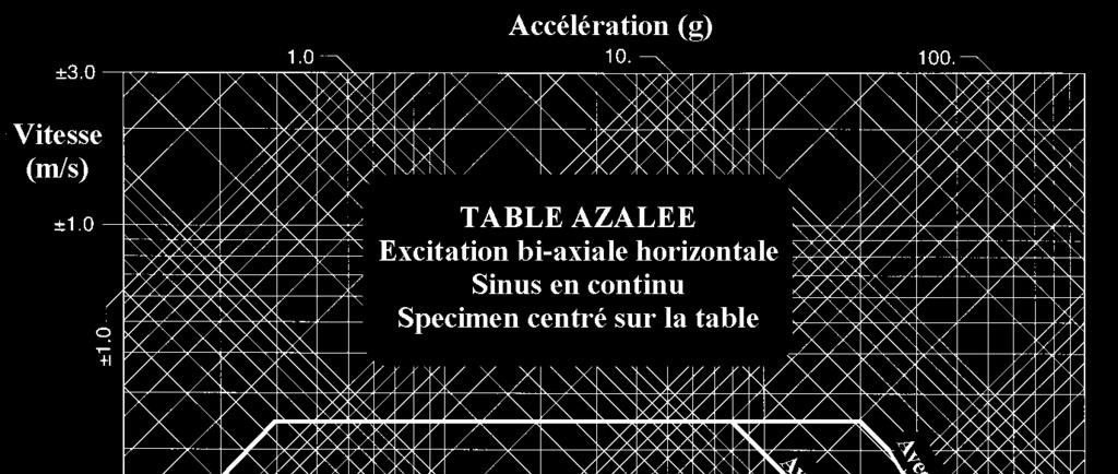
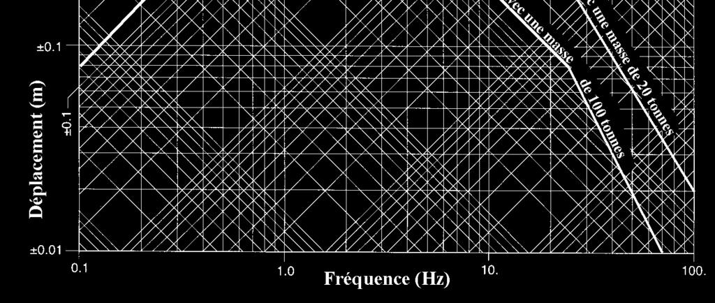
36 36 The plate The majority of the plates is made in steel. To increase the performance in acceleration, a solution is reducing the mass of the plate. For this reason, some plates have been made in aluminum alloy (for example AZALEE shaking table). The advantage is to decrease the mass, by this solution is more expensive, and the plates are more brittle and there are some problems for welding. The AZALEE shaking table has a 6 m x 6 m plate made in AG7 (aluminum alloy). The plate weights about 24 tons. 10/03/

37 SEISMIC ENGINEERING RESEARCH INFRASTRUCTURES FOR EUROPEAN SYNERGIES 37 To have a good control of the table and to not overload the mockup fixed to the plate, the natural frequencies of the plate must be over the frequency range of the time history. 10/03/


38 38 Mode 1 Mode 2 Mode 3 Mode 4 Mode 5 Mode 6 Test results free-free 80.5 Hz 95.7 Hz Hz Hz Hz Hz CAST3M free-free 82,4 Hz 100 Hz 120 Hz SAP - free-free 80 Hz 95 Hz 117 Hz Hz Hz Hz Mode 1 Mode 2 Mode 3 Mode 4 Mode 5 Mode 6 SAP plate fixed 54.3 Hz 54.3 Hz 65.7 Hz 73.5 Hz 73.5 Hz 99 Hz 10/03/
39 Hz 33,7 Hz 20 Hz Abaque pour les modes de flexion de la maquette 21,4 Hz 16 Hz Hz 10,6 Hz Chute de fréquence (% ) ,6 Hz 14,4 Hz SMART sur plaque rigide 10,6 Hz 11,1 Hz 7,3 Hz 10,6 Hz Camus Ox et Oy 6,8 Hz 5,3 Hz 8,02 Hz SMART sur plaque rigide 10,6 Hz 5,3 Hz 5,3 Hz 5 Hz 2,56 Hz 5,3 Hz 2,64 Hz Ecoleader 3,73 Hz 0 1,44 Hz Moment en pied de structure (t.m) = masse modale x hauteur du centre de masse modale 8 Hz 5,3 Hz 5 Hz 3 Hz Fréquence de la m aquette encastrée au sol 10/03/
.")
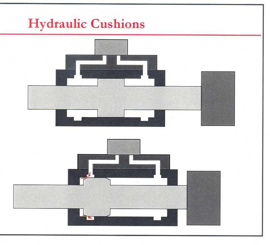
40 40 Accumulators The aims of these accumulators are: to increase the performances of the actuator (distortion and velocity) accumulator pressurized at 125 bars, to decrease hydraulic shocks in the piping (return line, accumulators pressurized at 3 bars). Discharge of the accumulator Accumulator Charging 10/03/


41 41 Some others accumulators can be placed directly on the hydraulic line to increase the power or the global flow of the testing facility. The accumulators are pressurized when the pumps starts and they give flow for a short duration when the testing facility needs oil. 10/03/
42 42 Bladder accumulators consist of a pressure vessel and an internal elastomeric bladder that contains the gas. The bladder is charged through a gas valve at the top of the accumulator, while a poppet valve at the bottom prevents the bladder from being ejected with the outflowing fluid. The poppet valve is sized so that maximum volumetric flow (typically to 15 liter/sec, but up to 140 liter/sec for high-flow designs) cannot be exceeded. The bladder can be replaced, usually through the fluid end of the vessel. To operate, the bladder is charged with nitrogen to a pressure specified by the manufacturer according to the operating conditions. When system pressure exceeds gas-precharge pressure of the accumulator, the poppet valve opens and hydraulic fluid enters the accumulator. The change in gas volume in the bladder between minimum and maximum operating pressure determines the useful fluid capacity. Piston accumulators have an outer cylinder tube, end caps, a piston element, and sealing system. The cylinder holds fluid pressure and guides the piston, which forms the separating element between gas and fluid. Charging the gas side forces the piston against the end cover at the fluid end. As system pressure exceeds the minimum operating level for the accumulator, the piston moves and compresses gas in the cylinder. Each type of separated, hydropneumatic accumulator has advantages, but bladder designs are generally considered the most versatile. For shock and pulsation, for example, bladder models are ideal. Piston units are not recommended because they are too slow to react to shock waves. 10/03/
 10/03/2010")
43 43 Oil pressure in a bladder accumulator ( or Floating piston accumulator) 10/03/
44 44 Open view of accumulators (hydro-pneumatic) bladder accumulator 10/03/
45 45 Open view of Floating piston accumulator 10/03/

46 46 Hydraulic power system The principal parts of a hydraulic power system are: a motor, a pump, a pressure regulator, a tank, a filtration system, an oil cooler. 10/03/

47 47 Several types of pump: Gear pumps - Vane pumps - Radial-piston pumps - Axial-piston swash-plate pump Output : Pressurrized oil Gear pumps Oil Input 10/03/


48 48 Several types of pump: Gear pumps - Vane pumps - Radial-piston pumps - Axial-piston swash-plate pump Vane pumps 10/03/

49 49 Radial-piston pumps 10/03/

50 50 Radial-piston pumps 10/03/

51 51 Radial-piston pumps 10/03/
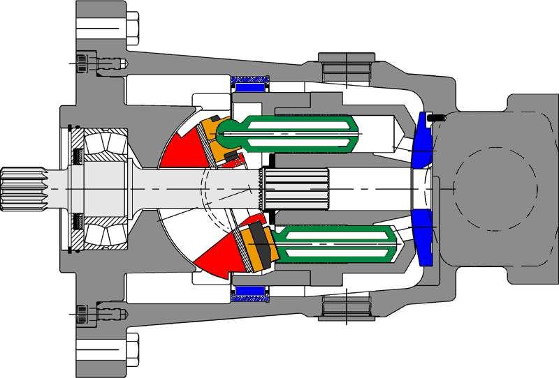
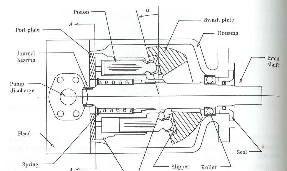
52 52 Axial-piston swash-plate pump 10/03/
53 53 Axial-piston swash-plate pump 10/03/
54 54 Axial-piston swash-plate pump 10/03/
55 55 Axial-piston swash-plate pump 10/03/
56 56 Variation of the output pressure/flow 10/03/

57 57 piston cylinder block Suction kidney Pressure kidney valve plate 10/03/
58 58 11 cm³ trapped volume 0.3 cm³ compression volume compression starts angle cm³ trapped volume 0.3 cm³ compression volume compression ends angle 12 standard pump 0.3 cm³ 11 angle 1.22 ms l/min ~21% of 69 l/min 10/03/
59 59 Pressure 400 bar Time ms Standard l/min 60 Flow Rotation 10/03/
60 60 piston cylinder block suction kidney valve plate pressure kidney Precompression volume 10/03/
61 61 11 cm³ trapped volume 0.3 cm³ compression volume compression starts 11 cm³ trapped volume 0.3 cm³ compression volume compression ends chamber refill starts angle cm³ trapped volume 0.3 cm³ compression volume chamber refill ends angle 12 angle 35 PVplus 0.3 cm³ 23 angle 2.56 ms 7.04 l/min 10% of 69 l/min 10/03/
62 62 10/03/
63 63 10/03/
64 64 Pressure ripple reduction 10/03/

65 65 Precom- pression volume 10/03/
66 66 Pump Housing Optimization reduces pump nois - absolute reduction in noise emission - frequency shift to better sound Precompression Volume Reduces Flow and Pressure Pulsation by 40-60% - no extra cost: additional casting core is offset by material saving - minor effect on pump noise - major effect on system noise 10/03/
67 67 Several type of regulation Bypass regulated constant pressure hydraulic power supply Stroke regulated constant pressure hydraulic power supply Constant pressure hydraulic power supply with servo load 10/03/

68 68 The oil Generally these oils are used: Shell TELLUS 46 or Mobil DTE 25 - Class of pollution ISO The ISO class of the oil is characterized by a code with 2 numbers relative to the number of particles with diameter > 5 microns/milli-liter and with diameter > 15 microns /milli-liter Example: Required Class ISO 13/9 13 = 400 to 800 particles size 5 microns 9 = 250 to 500 particles size 15 microns Limit Class: ISO15/11 - Bulk modulus (Compressibility) = à kg/cm² - Flash Point (temperature) = 236 C - Viscosity at 40 C = 46 mm²/s 10/03/
69 SEISMIC ENGINEERING RESEARCH INFRASTRUCTURES FOR EUROPEAN SYNERGIES 69 10/03/
3. DESCRIPTION OF SHAKING TABLE SYSTEM COMPONENTS
 17 3. DESCRIPTION OF SHAKING TABLE SYSTEM COMPONENTS 3.1. INTRODUCTION The earthquake simulator is a system that consists of several components which must be designed to effectively work together. Each
Seismic Engineering Research Infrastructures for European Synergies. JRA1: Small Lab Experience. Iasi 13th July 2009
 Seismic Engineering Research Infrastructures for European Synergies Structural Dynamics Research Group Department of Engineering Science University of Oxford JRA1: Small Lab Experience Iasi 13th July 2009
Test Which component has the highest Energy Density? A. Accumulator. B. Battery. C. Capacitor. D. Spring.
 Test 1 1. Which statement is True? A. Pneumatic systems are more suitable than hydraulic systems to drive powerful machines. B. Mechanical systems transfer energy for longer distances than hydraulic systems.
TUTORIAL QUESTIONS FOR THE INDUSTRIAL HYDRAULICS COURSE TEP 4205
 TUTORIAL QUESTIONS FOR THE INDUSTRIAL HYDRAULICS COURSE TEP 4205 The book for the course is Principles of Hydraulic System Design, by Peter J Chapple. Published by Coxmoor Publishing Co., UK. Available
What does pressure refer to in relation to hydrostatics and what is it dependent on?
 Question 1 [3 Marks] What does pressure refer to in relation to hydrostatics and what is it dependent on? Question 2 [14 Marks] Make a circuit diagram of a regular hydraulic plant that is used to control
test with confidence HV Series TM Test Systems Hydraulic Vibration
 test with confidence HV Series TM Test Systems Hydraulic Vibration Experience. Technology. Value. The Difference. HV Series TM. The Difference. Our philosophy is simple. Provide a system designed for optimum
CHAPTER 4: EXPERIMENTAL WORK 4-1
 CHAPTER 4: EXPERIMENTAL WORK 4-1 EXPERIMENTAL WORK 4.1 Preamble 4-2 4.2 Test setup 4-2 4.2.1 Experimental setup 4-2 4.2.2 Instrumentation, control and data acquisition 4-4 4.3 Hydro-pneumatic spring characterisation
LogSplitterPlans.Com
 Hydraulic Pump Basics LogSplitterPlans.Com Hydraulic Pump Purpose : Provide the Flow needed to transmit power from a prime mover to a hydraulic actuator. Hydraulic Pump Basics Types of Hydraulic Pumps
Directional servo-valve of 4-way design
 Courtesy of CM/Flodyne/Hydradyne Motion Control Hydraulic Pneumatic Electrical Mechanical (0) 426-54 www.cmafh.com Directional servo-valve of 4-way design Type 4WSE3E 32 Size 32 Component series 5X Maximum
MECHATRONICS LAB MANUAL
 MECHATRONICS LAB MANUAL T.E.(Mechanical) Sem-VI Department of Mechanical Engineering SIESGST, Nerul, Navi Mumbai LIST OF EXPERIMENTS Expt. No. Title Page No. 1. Study of basic principles of sensing and
Design and Modeling of Fluid Power Systems ME 597/ABE 591
 Systems ME 597/ABE 591 Dr. Monika Ivantysynova MAHA Professor Flud Power Systems MAHA Fluid Power Research Center Purdue University Systems Dr. Monika Ivantysynova, Maha Professor Fluid Power Systems Mivantys@purdue.edu
Hydraulic Proportional and Closed Loop System Design
 Hydraulic Proportional and Closed Loop System Design Neal Hanson Product Manager Industrial Valves and Electrohydraulics 1 Electrohydraulics Contents 1. Electrohydraulic Principles 2. Proportional Valve
Module 6 Assignment Part A
 Module 6 Assignment Part A TOTAL MARKS Part A = 192 TOTAL QUESTIONS Part A = 36 Question 1 [3 Marks] What does pressure refer to in relation to hydrostatics and what is it dependent on? Question 2 [14
TUTORIAL QUESTIONS FOR COURSE TEP 4195
 TUTORIL QUESTIONS FOR COURSE TEP 4195 Data: Hydraulic Oil Density 870 kg/m 3 bsolute viscosity 0.03 Ns/m 2 Spool valve discharge coefficient 0.62. 1) hydrostatic transmission has a variable displacement
TPV Variable Displacement Closed Loop System Axial Piston Pump THE PRODUCTION LINE OF HANSA-TMP HT 16 / M / 852 / 0815 / E
 HYDRAULIC COMPONENTS HYDROSTATIC TRANSMISSIONS GEARBOXES - ACCESSORIES Certified Company ISO 9001-14001 ISO 9001 Via M. L. King, 6-41122 MODENA (ITALY) Tel: +39 059 415 711 Fax: +39 059 415 729 / 059 415
Definitions of Technical Terms
 Definitions of Technical Terms ABSOLUTE A measure having as it s zero point of base the complete absence of the entity being measured. ABSOLUTE PRESSURE A pressure scale with zero point at a perfect vacuum.
HS CYCLIC CUM STATIC TRIAXIAL TEST SYSTEM
 HS28.610 CYCLIC CUM STATIC TRIAXIAL TEST SYSTEM Meets the essential requirements of ASTM-5311/3999 Introduction The system is a highly advanced combination of hydraulic and pneumatic technology where σ1
Lecture 6. This week: Lab 13: Hydraulic Power Steering [ Lab 14: Integrated Lab (Hydraulic test bench) ]
![Lecture 6. This week: Lab 13: Hydraulic Power Steering [ Lab 14: Integrated Lab (Hydraulic test bench) ]](/thumbs/84/91055223.jpg "Lecture 6. This week: Lab 13: Hydraulic Power Steering [ Lab 14: Integrated Lab (Hydraulic test bench) ]") 133 Lecture 6 This week: Lab 13: Hydraulic Power Steering [ Lab 14: Integrated Lab (Hydraulic test bench) ] 4-way directional control valve; proportional valve; servo-valve Modeling / Analysis of a servo-valve
133 Lecture 6 This week: Lab 13: Hydraulic Power Steering [ Lab 14: Integrated Lab (Hydraulic test bench) ] 4-way directional control valve; proportional valve; servo-valve Modeling / Analysis of a servo-valve
Steering Test Rigs. The World of Steering Test Machines. A world of experience TEST AND MOTION SIMULATION 2
 Steering Test Rigs The World of Steering Test Machines Steering column assemblies, are by their nature extremely safety critical, thus the ability to test them accurately and repeatedly is extremely important.
Content. Chapter 1 Hydraulic energy converters... 10
 Content Chapter 1 Hydraulic energy converters... 10 1.1 List of symbols... 13 1.2 Hydraulic pump types, constant output... 14 1.2.1 External gear pumps... 16 1.2.2 Internal gear pumps... 17 1.2.3 Vane
G761 Series Servovalves ISO Size 04
 G761 Series Servovalves ISO 137 Size 4 TWO STAGE SERVOVALVES G761 SERIES SERVOVALVES The G761 Series flow control servovalves are throttle valves for 3- and preferably 4-way applications.they are a high
631 Series Servovalves ISO 4401 Size 05
 631 Series Servovalves ISO 4401 Size 05 TWO STAGE SERVOVALVES 631 SERIES SERVOVALVES The 631 Series flow control servovalves are throttle valves for 3- and preferably 4-way applications.they are a medium
3/3 servo directional control valve with mechanical position feedback
 Courtesy of CMA/Flodyne/Hydradyne Motion Control Hydraulic neumatic Electrical Mechanical () 426-4 www.cmafh.com 3/3 servo directional control valve with mechanical position feedback Type 4WS2EM...XN...-114
Servo and Proportional Valves
 Servo and Proportional Valves Servo and proportional valves are used to precisely control the position or speed of an actuator. The valves are different internally but perform the same function. A servo
three different ways, so it is important to be aware of how flow is to be specified
 Flow-control valves Flow-control valves include simple s to sophisticated closed-loop electrohydraulic valves that automatically adjust to variations in pressure and temperature. The purpose of flow control
D633/D634 SERVOVALVES FOR ELECTROHYDRAULIC POSITION, VELOCITY, PRESSURE OR FORCE CONTROL SYSTEMS WITH HIGH DYNAMIC RESPONSE REQUIREMENTS
 SERVOVALVES DIRECT DRIVE SERVOVALVES D633/D634 SERVOVALVES FOR ELECTROHYDRAULIC POSITION, VELOCITY, PRESSURE OR FORCE CONTROL SYSTEMS WITH HIGH DYNAMIC RESPONSE REQUIREMENTS Rev. 2, 04/2009 ISO 4401 SIZES
Comparison - TE 80 and PCS HFFR
 Comparison - TE 80 and PCS HFFR For ISO 12156-1 and ASTM D6079 fuel lubricity standard tests, results from the TE 80 differ to those from the PCS HFRR. The TE 80 (and the TE 77 with low load adapter) consistently
Pneumatic Control System
 Matakuliah: Teknik Otomasi Pneumatic Control System Eka Maulana, ST, MT, MEng. What is Pneumatic? Pneumatics is a type of power transmission that uses a gas ( in our case, air) and pressure differential
SHOCK ABSORBER/DAMPER TESTING MACHINE
 SHOCK ABSORBER/DAMPER TESTING MACHINE Dampening force of a shock absorber is directly proportional to velocity and this parameter needs to be precisely controlled. A small variation of 1mm in a stroke
Directional servo-valve in 4-way design
 Directional servo-valve in 4-way design RE 2983/.11 Replaces: 7.3 1/ Type 4WS.2E... Size Component series X Maximum operating pressure 31 bar Maximum flow 1 l/min HD892 Type 4WSE2ED -X/...K31EV HD893 Type
Hydraulic Pump and Track Motor for Hydrostatic Transmission
 KYB TECHNICAL REVIEW No. 55 OCT. 2017 Product Introduction Hydraulic Pump and Track Motor for Hydrostatic Transmission INADA Takanori, MIURA Takuya, MATSUZAKA Keita 1 Introduction 2 Hydraulic Pumps There
LECTURE-23: Basic concept of Hydro-Static Transmission (HST) Systems
 Systems") MODULE-6 : HYDROSTATIC TRANSMISSION SYSTEMS LECTURE-23: Basic concept of Hydro-Static Transmission (HST) Systems 1. INTRODUCTION The need for large power transmissions in tight space and their control
MODULE-6 : HYDROSTATIC TRANSMISSION SYSTEMS LECTURE-23: Basic concept of Hydro-Static Transmission (HST) Systems 1. INTRODUCTION The need for large power transmissions in tight space and their control
Mechanical Engineering
 Mechanical Engineering Stepper Motor Drive Full step controlling of stepper Motor Single step, low and high speed, Forward and Reverse Small stepper Motor with driver and Power Circuit Necessary Power
Nomenclature... xi Hydraulic Laws, Theorems, and Equations...xii
 Nomenclature... xi Hydraulic Laws, Theorems, and Equations...xii 1 Introduction 1.1 Component Design Perspective...1 1.2 Hydraulic Power Evolution...2 1.3 Hydraulic Applications...6 1.4 Component Design
Finite Element and Experimental Validation of Stiffness Analysis of Precision Feedback Spring and Flexure Tube of Jet Pipe Electrohydraulic Servovalve
 Finite Element and Experimental Validation of Stiffness Analysis of Precision Feedback Spring and Flexure Tube of Jet Pipe Electrohydraulic Servovalve M. Singaperumal*, Somashekhar. S. Hiremath* R. Krishna
2. Hydraulic Valves, Actuators and Accessories. 24 Marks
 2. Hydraulic Valves, Actuators and Accessories 24 Marks Co related to chapter 602.2 Describe working principle of various components used in hydraulic & pneumatic systems. 602.3 Choose valves, actuators
Horizontal Table. Full lineup of IMV slip tables. *The specifications and design are subject to change without notice.
 Horizontal Table Full lineup of IMV slip tables http://www.imvglobal.com/ *The specifications and design are subject to change without notice. Feb. 2017 Cat No.1702 TBVEng. FNCLB V80D95L34 FNCLB V83D95L68
Lecture 7. Lab 14: Integrative lab (part 2) Lab 15: Intro. Electro-hydraulic Control Setups (2 sessions)
 Lab 15: Intro. Electro-hydraulic Control Setups (2 sessions)") Coming week s lab: Lecture 7 Lab 14: Integrative lab (part 2) Lab 15: Intro. Electro-hydraulic Control Setups (2 sessions) 4 th floor Shepherd (room # TBD) Guest lecturer next week (10/30/15): Dr. Denis
Coming week s lab: Lecture 7 Lab 14: Integrative lab (part 2) Lab 15: Intro. Electro-hydraulic Control Setups (2 sessions) 4 th floor Shepherd (room # TBD) Guest lecturer next week (10/30/15): Dr. Denis
D660 Series Servo-Proportional Control Valves with Integrated Electronics ISO 4401 Size 05 to 10
 D660 Series Servo-Proportional Control Valves with Integrated Electronics ISO 4401 Size 05 to 10 OVERVIEW Section Page MOOG SERVO-PROPORTIONAL CONTROL VALVES Overview 2 3 Technical Data 4 5 Electronics
Rexroth Hydraulics. Servo directional valve of 4-way design Type 4WS.2EM RE /03.99
 RE 29 564/03.99 Replaces: 29 563 Servo directional valve of 4-way design ype 4WS.2EM Nominal size 6 Series 2X Maximum operating pressures 210 / 315 bar Maximum flow 40 L/min H//D 5994/98 ype 4WS2EM 6-2X/.E...K17EV
VESPA: a servohydraulic shock testing machine P. Hunziker Defence Procurement Agency, NC Laboratory Spiez, CH-3700 Spiez, Switzerland
 VESPA: a servohydraulic shock testing machine P. Hunziker Defence Procurement Agency, NC Laboratory Spiez, CH-3700 Spiez, Switzerland Abstract Equipment installed in Swiss civil defense shelters and military
CH.4 Basic Components of Hydraulic and Pneumatic System/16 M HAP/17522/AE5G
 Content : 4.1 Hydraulic and Pneumatic actuators. 10 Marks Hydraulic Actuators - Hydraulic cylinders (single, double acting and telescopic) construction and working, Hydraulic motors (gear and piston type)
APS 420 ELECTRO-SEIS Long Stroke Shaker with Linear Ball Bearings Page 1 of 5
 Long Stroke Shaker with Linear Ball Bearings Page 1 of 5 The APS 420 ELECTRO-SEIS shaker is a long stroke, electrodynamic force generator specifically designed to be used alone or in arrays for studying
Servovalve Test Equipment ValveExpert 8.1
 Servovalve Test Equipment DIETZ automation GmbH 3 Introduction Figure 1: Manual mode of the Test Equipment. is an automatic test equipment for checking, maintenance, and adjustment of servoand proportional
G761 Series Servovalves ISO Size 04
 G761 Series Servovalves ISO 137 Size 4 TWO STAGE SERVOVALVES G761 SERIES SERVOVALVES The G761 Series flow control servovalves are throttle valves for 3-, and preferably 4-way applications.they are a high
SM4-30 Servovalves Flows to 113 l/min (30 USgpm) Pressures to 140 bar (2000 psi)
 Pressures to 140 bar (2000 psi)") Vickers Servo Valves SM4-30 Servovalves Flows to 113 l/min (30 USgpm) Pressures to 140 bar (2000 psi) Released 1/94 653 Introduction Vickers SM4-30 servovalves can provide system closed loop control with
Vickers Servo Valves SM4-30 Servovalves Flows to 113 l/min (30 USgpm) Pressures to 140 bar (2000 psi) Released 1/94 653 Introduction Vickers SM4-30 servovalves can provide system closed loop control with
Rotary Actuators. The World of Rotary Actuators. A world of experience TEST AND MOTION SIMULATION
 Rotary Actuators The World of Rotary Actuators Servotest produces two types of Rotary Actuators; Dual Vane, and Torque rotary actuators. By virtue of their design, both types of actuators, when used continuously,
Contents. Pressure measurement technology Pressure calibrators 18 Exercises 19-20
 1 Pressure Contents Topics: Slide No: Pressure measurement technology 03-17 Pressure calibrators 18 Exercises 19-20 2 Pressure Gauges Barometer Used to measure Barometric Pressure Reference is 0 psia,
CLOSED CIRCUIT HYDROSTATIC TRANSMISSION
 Energy conservation and other advantages in Mobile Equipment Through CLOSED CIRCUIT HYDROSTATIC TRANSMISSION C. Ramakantha Murthy Technical Consultant Various features/advantages of HST Hydrostatic transmissions
Lecture 6. Systems review exercise To be posted this weekend Due next Friday (3/6)
") 150 Systems review exercise To be posted this weekend Due next Friday (3/6) Lecture 6 Coming week: Lab 13: Hydraulic Power Steering Lab 14: Integrated Lab (Hydraulic test bench) Topics today: Pumps and
150 Systems review exercise To be posted this weekend Due next Friday (3/6) Lecture 6 Coming week: Lab 13: Hydraulic Power Steering Lab 14: Integrated Lab (Hydraulic test bench) Topics today: Pumps and
TPV Variable Displacement Axial Piston Pumps CONTENTS. General Information. Installation Instructions. Technical Specifications 6-7
 CONTENTS General Information Installation Instructions Technical Specifications Single Pump Installation Drawing Tandem Pump Installation Drawing Mounting Flanges and Shaft Details Rear Pump Mounting Flanges
4-way directional servo-valve
 4-way directional servo-valve RE 29564/09.10 Replaces: 01.07 1/12 Type 4WS.2E Size 6 Component series 2X Maximum operating pressure 315 bar Maximum flow 48 l/min HD5994 Table of contents Contents age Features
 Flow Line Controls Positioner Specifications Series 55 3-15 psi Pneumatic Series 56 4-20 ma Electro-Pneumatic Series 55 Series 56 Flow Line Controls, Inc. P.O. Box 677 Schriever, LA 70395 Phone: 985-414-6003
D661-G...A Series Servovalve With Bushing and Integrated 24 Volt Electronics ISO 4401 Size 05
 D661-G...A Series Servovalve With Bushing and Integrated 24 Volt Electronics ISO 4401 Size 05 OVERVIEW Section Page MOOG SERVO-PROPORTIONAL CONTROL VALVES Overview 2 3 Technical Data 4 5 Performance Specs.
APS 113 ELECTRO-SEIS Long Stroke Shaker with Linear Ball Bearings Page 1 of 5
 Long Stroke Shaker with Linear Ball Bearings Page 1 of 5 The ELECTRO-SEIS shaker is a long stroke, electrodynamic force generator specifically designed to be used alone or in arrays for studying dynamic
72 Series Servovalves
 72 Series Servovalves TWO STAGE SERVOVALVES 72 SERIES SERVOVALVES The 72 Series flow control servovalves are throttle valves for 3 and preferably 4-way applications.they are a high performance, two-stage
Starting up hydraulic systems
 General / Installation A hydraulic system that operates economically, safely, and trouble-free requires careful planning, as well as proper installation and start-up. Conscientious maintenance has a considerable
Advanced Modeling Techniques and Innovations in External Gear Pumps
 Advanced Modeling Techniques and Innovations in External Gear Pumps Andrea Vacca Associate Professor Maha Fluid Power Research Center Purdue University, West Lafayette, IN (USA) https://engineering.purdue.edu/maha/
771, 772, 773 Series Servovalves
 771, 772, 773 Series Servovalves TWO STAGE SERVOVALVES 771/2/3 SERIES SERVOVALVES The 771/2/3 Series flow control servovalves are throttle valves for 3- and preferably 4-way applications.they are a high
4/3-way high response directional control valve pilot operated with electrical feedback and integrated electronics (OBE)
") 4/3-way high response directional control valve pilot operated with electrical feedback and integrated electronics (OE) ype 4WRDE Nominal size to 35 Component series 5X Maximum operating pressure 3 bar
4/3-way high response directional control valve pilot operated with electrical feedback and integrated electronics (OE) ype 4WRDE Nominal size to 35 Component series 5X Maximum operating pressure 3 bar
UŽSISAKYKITE internetu telefonu el. paštu
 Features Axial piston pump MA10VO in swashplate design is used in open loop circuits. Flow is proportional to drive speed and displacement. By adjusting the position of the swashplate it is possible to
THE DYNAMIC CHARACTERISTICS OF A DIRECT-ACTING WATER HYDRAULIC RELIEF VALVE WITH DOUBLE DAMPING: NUMERICAL AND EXPERIMENTAL INVESTIGATION
 THE DYNAMIC CHARACTERISTICS OF A DIRECT-ACTING WATER HYDRAULIC RELIEF VALVE WITH DOUBLE DAMPING: NUMERICAL AND EXPERIMENTAL INVESTIGATION Yipan DENG * Yinshui LIU * Defa WU * Hui LI * * State Key Laboratory
EXPERIMENTAL RESEARCH OF PROPERTIES OF HYDRAULIC DRIVE FOR VALVES OF INTERNAL COMBUSTION ENGINES
 Journal of KONES Powertrain and Transport, Vol. 0, No. 1 013 EXPERIMENTAL RESEARCH OF PROPERTIES OF HYDRAULIC DRIVE FOR VALVES OF INTERNAL COMBUSTION ENGINES Tomasz Szyd owski, Mariusz Smoczy ski Technical
Input, Control and Processing elements
 PNEUMATIC & HYDRAULIC SYSTEMS CHAPTER FIVE Input, Control and Processing elements Dr. Ibrahim Naimi Valves The function of valves is to control the fluid path or the pressure or the flow rate. Depending
SM4-10/12/15 Servovalves Flows to 57 l/min (15 USgpm) Pressures to 210 bar (3000 psi)
 Pressures to 210 bar (3000 psi)") Vickers Servo Valves SM4-10/12/15 Servovalves Flows to 57 l/min (15 USgpm) Pressures to 210 bar (3000 psi) Released 12/93 651 Introduction Vickers SM4-10/12/15 servovalves can provide system closed loop
Vickers Servo Valves SM4-10/12/15 Servovalves Flows to 57 l/min (15 USgpm) Pressures to 210 bar (3000 psi) Released 12/93 651 Introduction Vickers SM4-10/12/15 servovalves can provide system closed loop
GoTo Europe Focused Delivery Program. Product overview Industrial and Mobile Hydraulics
 GoTo Europe Focused Delivery Program Product overview Industrial and Mobile Hydraulics 2 GoTo Europe You have hardly any time to complete your order before your delivery arrives Nowadays, every day counts
PROPORTIONAL VALVES SERVO VALVES. Maximum operating pressure MPa {kgf/cm 2 } Model [Model No.]
![PROPORTIONAL VALVES SERVO VALVES. Maximum operating pressure MPa {kgf/cm 2 } Model [Model No.]](/thumbs/82/85298236.jpg "PROPORTIONAL VALVES SERVO VALVES. Maximum operating pressure MPa {kgf/cm 2 } Model [Model No.]") J PROPORTIONAL VALVES SERVO VALVES J Model [Model No.] Solenoid pilot operated proportional relief valve [JRP] Solenoid operated proportional relief valve [JRPL] Type C2 solenoid operated proportional
J PROPORTIONAL VALVES SERVO VALVES J Model [Model No.] Solenoid pilot operated proportional relief valve [JRP] Solenoid operated proportional relief valve [JRPL] Type C2 solenoid operated proportional
GPM Hydraulic Consulting, Inc. P.O. Box 689. Social Circle, GA Hydraulic Consulting, Inc
 Hydraulic Consulting, Inc This special promotional CD is to demonstrate how your hydraulic troubleshooting manual can be ordered as an Adobe Acrobat ebook. It can be installed on any computer with the
Topic 1. Basics of Oil Hydraulic Systems
 Topic 1. Basics of Oil Hydraulic Systems Fluid power Fluid power is the technology that deals with the generation, control and transmission of forces and movement of mechanical element or system with the
Air Bearing Shaker for Precision Calibration of Accelerometers
 Air Bearing Shaker for Precision Calibration of Accelerometers NOMENCLATURE Jeffrey Dosch PCB Piezotronics 3425 Walden Avenue, Depew NY DUT Device Under Test S B DUT sensitivity to magnetic field [(m/sec
KVF. Flow Control Servovalve (FCS) DESCRIPTION FEATURES ORDERING INFORMATION KVF X X X X X. BLN Issued: February 2004
 DESCRIPTION FEATURES ORDERING INFORMATION KVF X X X X X. BLN Issued: February 2004") DESCRIPTION KVF Flow Control Servovalve (FCS) Issued: February 004 The KVF Flow Control Servovalve is a precision servovalve that provides an output flow rate proportional to a low power electrical input
DESCRIPTION KVF Flow Control Servovalve (FCS) Issued: February 004 The KVF Flow Control Servovalve is a precision servovalve that provides an output flow rate proportional to a low power electrical input
Hydrostatic Drive. 1. Main Pump. Hydrostatic Drive
 Hydrostatic Drive The Hydrostatic drive is used to drive a hydraulic motor at variable speed. A bi-directional, variable displacement pump controls the direction and speed of the hydraulic motor. This
FLOW CONTROL SERVOVALVES
 FLOW CONTOL SEVOVALVES TWO STAGE SEVOVALVES FO INDUSTIAL APPLICATIONS What moves your world OUTLINE J869 Series flow control servovalves are throttle valves for 3 and preferably 4 way applications. They
Vibration Test Systems. ibratio
 ibratio Lansmont Vibration Test Systems are versatile, easy to operate, and reliable servo-hydraulic vibration testing equipment. Whether you are testing bare products, individual packages, full pallet
Vibration Test Systems
 Vibration Test Systems Lansmont Vibration Test Systems are versatile, easy to operate, and reliable servo-hydraulic vibration testing equipment. Whether you are testing bare products, individual packages,
D680 Series Mini Direct Drive Valve Piloted Servo-Proportional Control Valves with Integrated Electronics ISO 4401 Size 05 to 08
 D68 Series Mini Direct Drive Valve Piloted Servo-Proportional Control Valves with Integrated Electronics ISO 441 Size 5 to 8 OVERVIEW Section Page MOOG SERVO-PROPORTIONAL CONTROL VALVES Overview 2 3 Technical
Design and experiment of hydraulic impact loading system for mine cable bolt
 Procedia Earth and Planetary Science 1 (2009) 1337 Procedia Earth and Planetary Science www.elsevier.com/locate/procedia The 6 th International Conference on Mining Science & Technology Design and experiment
2 Poster Motorcycle Ride Simulator
 2 Poster Motorcycle Ride Simulator The World of Ride Simulators The 2 Poster Motorcycle Road Simulator System is designed to reproduce responses experienced under normal driving conditions, to test motorcycle
HYDRAULICS VINCKE HYDRAULIC PUMPS
 VINCKE HYDRAULIC PUMPS TECH-VHP200.1 index 3 link to your page / link a su página Gear pumps Introduction 3 Group 0 3 Group 1 3 Group 2 3 Group 3 4 6 7 12 18 Variable displacement pumps 21 Hand pumps 3
Influence of Cylinder Bore Volume on Pressure Pulsations in a Hermetic Reciprocating Compressor
 Purdue University Purdue e-pubs International Compressor Engineering Conference School of Mechanical Engineering 2014 Influence of Cylinder Bore Volume on Pressure Pulsations in a Hermetic Reciprocating
3/3-Way-Proportional Valve
 3/3-Way-Proportional Valve Content Page General Description 1 Design 2 Function 2 Technical Data 3 Options 4 Dimensions 5 Accessories 6 Flow Curves 7 General Description This proportional valve in combination
Lecture 6. Systems review exercise To be posted this afternoon Due in class (10/23/15)
") 153 Systems review exercise To be posted this afternoon Due in class (10/23/15) Lecture 6 Coming week: Lab 13: Hydraulic Power Steering Lab 14: Integrated Lab (Hydraulic test bench) Topics today: 2 min
153 Systems review exercise To be posted this afternoon Due in class (10/23/15) Lecture 6 Coming week: Lab 13: Hydraulic Power Steering Lab 14: Integrated Lab (Hydraulic test bench) Topics today: 2 min
Considerations on Flow Regeneration Circuits and Hydraulic Motors Speed Variation at Constant Flow
 Considerations on Flow Regeneration Circuits and Hydraulic Motors Speed Variation at Constant Flow PhD. eng. Teodor Costinel POPESCU 1, Dipl. eng. lina Iolanda POPESCU 2, PhD. student eng. lexandru MRINESCU
APS 400 ELECTRO-SEIS. Long Stroke Shaker Page 1 of 5. Applications. Features
 Long Stroke Shaker Page 1 of 5 The APS 400 ELECTRO-SEIS is a force generator specifically designed to be used alone or in arrays for studying dynamic response characteristics of various structures. It
Automatic Back-Flushing Filter AutoFilt RF9.
 Automatic Back-Flushing Filter AutoFilt RF9. AutoFilt RF9 Clearing the Way. The Challenge: In response to the Tier III standard which will come into effect in 2016, the International Maritime Organization
STI LVDT Displacement Sensors
 STI LVDT Displacement Sensors The LVDT Still the most reliable and widely used displacement transducer available today. The best performance to cost ratio of any of its rival products in today s market.
Hydraulic Pumps Classification of Pumps
 Fluidsys Training Centre, Bangalore offers an extensive range of skill-based and industry-relevant courses in the field of Pneumatics and Hydraulics. For more details, please visit the website: https://fluidsys.org
Four-Quadrant Multi-Fluid Pump/Motor
 Georgia Institute of Technology Marquette University Milwaukee School of Engineering North Carolina A&T State University Purdue University University of California, Merced University of Illinois, Urbana-Champaign
Hydraulics. Axial Piston Pumps Series PVP. Introduction. With thru shaft option for multiple pump options Swash plate type for open circuit
 Introduction *not included Pump with standard compensator, code: "omit" With thru shaft option for multiple pump options Swash plate type for open circuit Pump with load sensing, code: "A" Mounting style
Appendix B. Glossary of Terms. Absolute pressure: The pressure above absolute pressure. It is the sum of atmospheric pressure and gauge pressure.
 Appendix B Glossary of Terms Absolute pressure: The pressure above absolute pressure. It is the sum of atmospheric pressure and gauge pressure. Absolute zero pressure: The reference zero that is not the
DESCRIPTION & OPERATION
 DESCRIPTION & OPERATION BRAKE BOOSTER Delco-Moraine Single Diaphragm A combined vacuum-hydraulic unit which uses a combination of intake manifold vacuum and atmospheric pressure to provide power assist.
Systems. Dynamic Test. Electrodynamic Vibration Test Systems
 Systems 100 - water 120 kn cooled Electrodynamic Vibration Test Systems SW3-10480APP (100KN) SW3-10LS3-550APP (100KN) SW3-10650APP (100KN) SW3-12480APP (120KN) SW3-12LS3-550APP (120KN) Dynamic Test Technical
LECTURE 27 SERVO VALVES FREQUENTLY ASKED QUESTIONS
 LECTURE 27 SERVO VALVES FREQUENTLY ASKED QUESTIONS 1. Define a servo valve Servo valve is a programmable orifice. Servo valve is an automatic device for controlling large amount of power by means of very
THE VARIATION OF POWER OBTAINED BY SERIAL AND PARALLEL CONNECTION OF A SHOCK ABSORBER ENERGY RECOVERY SYSTEM INSTALLED ON A HYBRID HYDRAULIC VEHICLE
 THE VARIATION OF POWER OBTAINED BY SERIAL AND PARALLEL CONNECTION OF A SHOCK ABSORBER ENERGY RECOVERY SYSTEM INSTALLED ON A HYBRID HYDRAULIC VEHICLE 1 Vlad Şerbănescu *, Horia Abăitancei, Gheorghe-Alexandru
Series 20 Axial Piston Pumps. Technical Information
 Series 20 Axial Piston Pumps Technical Information General Description INTRODUCTION Sauer-Danfoss a world leader in hydraulic power systems has developed a family of axial piston pumps. DESCRIPTION Sauer-Danfoss
Robot components: Actuators
 Robotics 1 Robot components: Actuators Prof. Alessandro De Luca Robotics 1 1 Robot as a system program of tasks commands Robot actions working environment mechanical units supervision units sensor units
variable displacement DELTA SAE Serie m i
 variable displacement pumps DELTA SAE Serie m i Contents xxx Range and characteristics... 1 Dimensions... 2 Performance.... 5 Control devices.... 4 to 8 Under development Delta pump with constant torque
An Introduction to Fatigue Testing Equipment, Test Setup & Data Collection
 An Introduction to Fatigue Testing Equipment, Test Setup & Data Collection Lisa Goodwin Servohydraulic Sales Specialist & Market Manager - Instron The difference is measurable 1 Themes.. Certainty of Measurement
TPV Variable Displacement Closed Loop System Axial Piston Pump MANUFACTURING THE PRODUCTION LINE OF HANSA-TMP HT 16 / M / 403 / 1110 / E
 HYDRAULIC COMPONENTS HYDROSTATIC TRANSMISSIONS GEARBOXES - ACCESSORIES Via M. L. King, 6-41122 MODENA (ITALY) Tel: +39 059 415 711 Fax: +39 059 415 729 / 059 415 730 INTERNET: http://www.hansatmp.it E-MAIL:
SECTION DOMESTIC-WATER PACKAGED BOOSTER PUMPS
 SECTION 221123.13 - DOMESTIC-WATER PACKAGED BOOSTER PUMPS PART 1 - GENERAL 1.1 RELATED DOCUMENTS A. Drawings and general provisions of the Contract, including General and Supplementary Conditions and Division