Service Manual. Fuller Heavy Duty Transmissions. Fuller Heavy Duty Transmissions. October 2007 TRSM0300. More time on the road
|
|
|
- Thomasina Sharon Ball
- 5 years ago
- Views:
Transcription
1 Fuller Heavy Duty Transmissions More time on the road Service Manual Fuller Heavy Duty Transmissions TRSM0300 October 2007 RTO-11607L RTO-11607L RTO-11607LL RTO-11607LL RTOF-11607L RTOF-11607LL
2
3 TABLE OF CONTENTS FOREWORD MODEL DESIGNATIONS AND SPECIFICATIONS LUBRICATION OPERATION (L) Models (LL) Models POWER FLOW TIMING TORQUE RECOMMENDATIONS TOOL REFERENCE PREVENTIVE MAINTENANCE PRECAUTIONS DISASSEMBLY INSPECTION REASSEMBLY CHANGING INPUT SHAFT AIR SYSTEM RANGE SHIFT AI R SYSTEM: ALL MODELS DEEP REDUCTION AIR SYSTEM: (LL) Models AI R SYSTEM SCHEMATICS DISASSEMBLY AND REASSEMBLY - SHIFTING CONTROLS AIR SYSTEM GEAR SHIFT LEVER HOUSING ASSEMBLY SHIFT BAR HOUSING ASSEMBLY REMOVAL - COMPANION FLANGE, AUXILIARY SECTION AND CLUTCH HOUSING DISASSEMBLY - AUXILIARY SECTION (L) Models... REASSEMBLY - AUXILIARY SECTION (L) Models.... DISASSEMBLY - AUXILIARY SECTION (LL) Models.. REASSEMBLY - AUXILIARY SECTION (LL) Models... DISASSEMBLY - FRONT SECTION REASSEMBLY - FRONT SECTION INSTALLATION - COMPANION FLANGE, AUXILIARY SECTION AND CLUTCH HOUSING INSTALLATION - SHIFTING CONTROLS SHIFT BAR HOUSING ASSEMBLY GEAR SHIFT LEVER HOUSING ASSEMBLY AIR SYSTEM
4 FOREWORD This manual is designed to provide detailed information necessary to service and repair the Fuller Transmissions listed on the cover. As outlined in the Table of Contents, the manual is divided into 3 main sections: a. Technical information and reference b. Removal, disassembly, reassembly and installation c. Options The format of the manual is designed to be followed in its entirety if complete disassembly and reassembly of the transmission is necessary. But if only one component of the transmission needs to be repaired, refer to the Table of Contents for the page numbers showing that component. For example, if you need to work on the Shift Bar Housing, you will find instructions for removal, disassembly and reassembly on page 47. Instructions for installation are on page 131. Service Manuals, Illustrated Parts Lists, Drivers Instructions, Driver Training Programs and other forms of product service information for these and other Fuller Transmissions are available upon request. A Technical Literature Order Form may be found in the back of this manual*. You may also obtain Service Bulletins, detailing information on product improvements, repair procedures and other servicerelated subjects by writing to the following address: EATON CORPORATION TRANSMISSION DIVISION Technical Service Department P.O. Box 4013 Kalamazoo, Michigan (616) Every effort has been made to ensure the accuracy of all information in this brochure. However, Eaton Transmission Division makes no expressed or implied warranty or representation based on the enclosed information. Any errors or omissions may be reported to Marketing Communications, Eaton Transmission Division, P.O. Box 4013, Kalamazoo, Ml
5 MODEL DESIGNATIONS AND SPECIFICATIONS IMPORTANT: All Fuller Transmissions are identified by model and serial number. This information is stamped on the transmission identification tag and affixed to the case. DO NOT REMOVE OR DESTROY THE TRANSMISSION IDENTIFICATION TAG. Gear Ratios Model Deep Reduction Low Range High Range Reverse Rev. LO-LO LO 1st 2nd 3rd 4th 5th 6th 7th OD Low/High RTO-11607L _ /3.33 RTO-11607LL /3.33
6 LUBRICATION Proper Lubrication... the Key to long transmission life Proper lubrication procedures are the key to a good all-around maintenance program. If the oil is not doing its job, or if the oil level is ignored, all the maintenance procedures in the world are not going to keep the transmission running or assure long transmission life. Eaton Fuller Transmissions are designed so that the internal parts operate in a bath of oil circulated by the motion of gears and shafts. Thus, ail parts will be amply lubricated if these procedures are closely followed: 1. Maintain oil level. Inspect regularly. 2. Change oil regularly. 3. Use the correct grade and type of oil. 4. Buy from a reputable dealer. I I I I I I I I Lubrication Change and Inspection Eaton Roadranger CD50 Transmission Fluid HIGHWAY USE Heavy Duty and Mid-Range First 3,000 to 5,000 miles Factory fill (4827 to 8045 Km) Inltlal drain Every 10,000 miles Check fluid level (16090 Km) Check for leaks Heavy Duty Highway Change Interval Every 250,000 miles Change transmission ( Km) fluid, Mid-Range Highway Change Interval Every 100,000 miles (160,000 Km) or every 3 years whichever occurs first First 30 hours Every 40 hours Every 500 hours Every 1,000 hours OFF-HIGHWAY USE Change transmission fluid. Factory fill Initial drain, Inspect fluid level Check for leaks Change transmission fluid where severe dirt conditions exist. Change transmission fluid (Normal off-highway use), Heavy Duty Engine Lubricant or Mineral Gear Lubricant HIGHWAY USE First 3,000 to 5,000 miles Factory fill (4827 to 8045 Km) Initial drain. Every 10,000 miles Inspect Iubricant level, (16090 Km) Check for leaks, Every 50,000 miles Change transmission (80450 Km) lubricant, OFF-HIGHWAY USE First 30 hours Change transmission lubricant on new units Every 40 hours Inspect Iubricant level Check for leaks Every 500 hours Change transmission Iubricant where severe dirt conditions exist. Every 1,000 hours Change transmission Iubricant (Normal off-highway use), Change the oil filter when fluid or lubricant is changed. Type Recommended Lubricants Grade (SAE) Fahrenheit (Celsius) Ambient Temperature Eaton Roadranger CD50 Transmission Fluid 50 All Heavy Duty Engine 011 MI L-L-2104B C or D or 50 Above 10 o F(-12 o C.) API-SF or API-CD 40 Above 10 o F(-12 o C.) (Previous API designations 30 Below 10 o F(-12 o C.) acceptable) Mineral Gear 011 with rust 90 Above 10 o F(-12 o C.) and oxidation Inhibitor 80W Below 10 o F(-12 o C.) API-GL-1 The use of mild EP gear oil or multi-purpose gear oil is not recommended, but if these gear oils are used, be sure to adhere to the following limitations: Do not use mild EP gear oil or multi-purpose gear oil when operating temperatures are above 230 F (110 o C). Many of these gear oils, particularly 85W140, break down above 230 F and coat seals, bearings and gears with deposits that may cause premature failures. If these deposits are observed (especially a coating on seal areas causing oil leakage), change to Eaton Roadranger CD50 transmission fluid, heavy duty engine oil or mineral gear oil to assure maximum component life and to maintain your warranty with Eaton. (Also see Operating Temperatures.) Additives and friction modifiers are not recommended for use in Eaton Fuller transmissions. Proper Oil Level Make sure oil is level with filler opening. Because you can reach oil with your finger does not mean oil is at proper level. One inch of oil level is about one gallon of oil. Draining Oil Drain transmission while oil is warm. To drain oil remove the drain plug at bottom of case. Clean the drain plug before re-installing. Refilling Clean case around filler plug and remove plug from side of case. Fill transmission to the level of the filler opening. If transmission has two filler openings, fill to level of both openings. The exact amount of oil will depend on the transmission inclination and model. Do not over fill this will cause oil to be forced out of the transmission. When adding oil, types and brands of oil should not be mixed because of possible in- 4 compatibility.,.....
7 LUBRICATION Operating Temperatures With Eaton Roadranger CD50 Transmission Fluid Heavy Duty Engine Oil and Mineral Oil The transmission should not be operated consistently at temperatures above 250 o F (120 o C). However, intermittent operating temperatures to 300 o F (149 o C) will not harm the transmission. Operating temperatures above 250 o F increase the lubricant s rate of oxidation and shorten its effective life. When the average operating temperature is above 250 o F, the transmission may require more frequent oil changes or external cooling. The following conditions in any combination can cause operating temperatures of over 250 o F: (1) operating consistently at slow speeds, (2) high ambient temperatures, (3) restricted air flow around transmission, (4) exhaust system too close to transmission, (5) high horsepower, overdrive operation. External oil coolers are available to reduce operating temperatures when the above conditions are encountered. Proper Lubrication Levels as Related to Transmission Installation Angles If the transmission operating angle is more than 12 degrees, improper lubrication can occur. The operating angle is the transmission mounting angle in the chassis plus the percent of upgrade (expressed in degrees). The chart below illustrates the safe percent of upgrade on which the transmission can be used with various chassis mounting angles. For example: if you have a 4 degree transmission mounting angle, then 8 degrees (or 14 percent of grade) is equal to the limit of 12 degrees. If you have a O degree mounting angle, the transmission can be operated on a 12 degree (21 percent) grade. Anytime the transmission operating angle of 12 degrees is exceeded for an extended period of time the transmission should be equipped with an oil pump or cooler kit to insure proper lubrication. Note on the chart the effect low oil levels can have on safe operating angles. Allowing the oil level to fall 1/2 below the filler plug hole reduces the degree of grade by approximately 3 degrees (5.5 percent). Proper Lubrication Levels are Essential! Transmission Oil Coolers are: Recommended With engines of 350 H.P. and above with overdrive transmissions Required With engines 399 H.P. and above with overdrive transmissions and GCW S over 90,000 lbs. With engines 399 H.P. and above and 1400 Lbs.-Ft. or greater torque With engines 450 H.P. and above With EP or Multipurpose Gear Oil Mild EP gear oil and multipurpose gear oil are not recommended when lubricant operating temperatures are above 230 F (110). In addition, transmission oil coolers are not recommended with these gear oils since the oil cooler materials may be attacked by these gear oils. The lower temperature limit and oil cooler restriction with these gear oils generally limit their success to milder applications. Transmission Mounting Angle Dotted line showing 2 Quarts Low is for reference only. Not recommended.
8 OPERATION Shift Lever Patterns and Shifting Controls
 1.")
9 POWER FLOW The transmission must efficiently transfer the engine's power, in terms of torque, to the vehicle's rear wheels. Knowledge of what takes place in the transmission during torque transfer is essential when trouble-shooting and making repairs as they become necessary. Front Section Power Flow: (Both Models) 1. Power (torque) from the vehicle's engine is transferred to the transmission's input shaft. 2. Splines of input shaft engage internal splines in hub of main drive gear. 3. Torque is split between the two countershaft drive gears. 4. Torque is delivered along both countershaft to mating countershaft gears of "engaged" mainshaft gear. The cross section view shown below illustrates LO/LO gear engagement. 5. Internal clutching teeth in hub of engaged mainshaft gear transfers torque to mainshaft through sliding clutch. 6. Mainshaft transfers torque directly to auxiliary drive gear. Auxiliary Section Power Flow: (RTO-11607LL LO/LO) 7. The auxiliary drive gear splits torque between the two auxiliary countershaft drive gears. 8. Torque is delivered along both auxiliary countershaft to the mating "engaged" deep reduction gear on output shaft. 9. Torque is transferred to output shaft through sliding clutch. 10. Output shaft delivers torque to driveline as LO/LO. DEEP REDUCTION POWER FLOW Figure 1


10 POWER FLOW Auxiliary Section Power Flow: LOW RANGE (All Models) The auxiliary drive gear splits torque between the two auxiliary countershaft drive gears. 9. Torque is delivered along both countershaft to "engaged" low range gear on range mainshaft or 10. output shaft. Torque is transferred to range mainshaft or output shaft through sliding clutch. Torque is delivered to driveline as LOW RANGE. LOW RANGE POWER FLOW (RTO-11607L Model Shown) Figure 2. Auxiliary Section Power Flow: HIGH RANGE (All Models) 7. The auxiliary drive gear transfers torque directly to 8. Torque is delivered through range mainshaft the range mainshaft or output shaft through and/or output shaft to driveline as HIGH RANGE "engaged" sliding clutch. 4th. 7 HIGH RANGE POWER FLOW (RTO-11607L Model Shown) Figure 3.
11 TIMING All Fuller twin countershaft transmissions are timed at assembly. It is important that proper timing procedures are followed when reassembling the transmission. Timing assures that the countershaft gears will contact the mating mainshaft gears at the same time, allowing mainshaft gears to center on the mainshaft and equally divide the load. Timing is a simple procedure of marking the appropriate teeth of a gear set prior to installation and placing them in proper mesh while in the transmission. In the front section, it is necessary to ime only he drive gear set. And depending on the model, only the low range or deep reduction gear set is timed in the auxiliary section. C. Meshing marked countershaft gear teeth with marked drive gear teeth. (After installing drive gear and mainshaft assemblies, the countershaft bearings are installed to complete countershaft installation.) 1. When installing bearings on the left countershaft, mesh the marked countershaft gear tooth between two marked teeth on the drive gear. Repeat the procedure when installing the right countershaft bearings. (See Illustration c.) A. Marking countershaft drive gear teeth. 1. Prior to placing each countershaft assembly into case, clearly mark on each drive gear the gear tooth which is directly over the keyway in gear. (See illustration A.) This tooth is stamped with an O to aid identification. C. COUNTERSHAFT GEAR TEETH MESHED WITH DRIVE GEAR TEETH FOR CORRECT TIMING A. TOOTH ON COUNTERSHAFT DIRECTLY OVER KEYWAY MARKED FOR TIMING B. Marking drive gear teeth. 1. Mark any two adjacent teeth on the drive gear. 2. Mark the two adjacent teeth on the drive gear which are directly opposite the first set marked. There should be an equal number of teeth between the markings on each side of gear. (See Illustration B.) B. DRIVE GEAR TEETH CORRECTLY MARKED FOR TIMING D. Timing auxiliary section. (In the auxiliary section, the low speed gear set is marked for timing instead of the drive gear set. ) 1. Mark any two adjacent teeth on the large mainshaft low speed gear, then mark the two adjacent teeth directly opposite the same procedure as used when marking the front section drive gear. 2. On each auxiliary countershaft assembly, mark the tooth on the small low speed gear which is stamped with an O. 3. Install the low speed gear and tailshaft assembly in auxiliary housing. 4. Partially install outer races of countershaft rear bearings in case bores. 5. Place the auxiliary countershaft assemblies into position, meshing marked tooth on each countershaft gear between marked teeth on low speed gear. Countershafts will be partially seated in rear bearing. 6. Fully install rear bearings to complete auxiliary countershaft installation.
12 TORQUE RECOMMENDATIONS Correct torque application is extremely important to assure long transmission life and dependable performance. Over-tightening or under-tightening can result in a loose installation and, in many instances, eventually cause damage to transmission gears, shafts, and/or bearings. Use a torque wrench whenever possible to attain recommended lbs./ft. ratings. Do not torque capscrews dry. FRONT SECTION: ALL MODELS
13 TORQUE RECOMMENDATIONS Cut 7191A
14 TOOL REFERENCE Some repair procedures pictured in this manual show The specialized tools listed below can be obtained the use of specialized tools. Their actual use is from a tool supplier or made from dimensions as recommended as they make transmission repair required by the individual user. Detailed Fuller@ Tool easier, faster, and prevent costly damage to critical Prints are available upon request by writing. parts. But for the most part, ordinary mechanic s tools such Eaton Corporation as socket wrenches, screwdrivers, etc., and other Transmission Division standard shop items such as a press, mauls and soft Technical Service Dept. bars are all that is needed to successfully disassemble P.O. Box 4013 and reassemble any Fuller Transmission. Kalamazoo, Michigan PAGE TOOL HOW OBTAINED 57 Auxiliary Section Hanger Bracket 46 Tension Spring Driver Made from Fuller Print T Made from Fuller Print T Snap Ring Pliers Tool Supplier 101 Impact Puller (1/2-13 Threaded End) Tool Supplier 94 Bearing Drivers (Flanged-End) 87 Quill Snap Ring Installer Made from Fuller Print Series T-10842* Made from Fuller Print T F 127 Torque Wrench, 1000 Lbs./Ft. Capacity Tool Supplier 98 Input Shaft Nut Installer Made from Fuller Print T A Dimensions necessary to determine specific tool number required.

15 PREVENTIVE MAINTENANCE CHECK CHART
16 PREVENTIVE MAINTENANCE PREVENTIVE MAINTENANCE CHECK CHART CHECKS WITHOUT PARTIAL DISASSEMBLY OF CHASSIS OR CAB Air System and Connections a. Check for leaks, worn air lines, loose connections and capscrews. See AIR SYSTEM. Clutch Housing Mounting a. Check all capscrews in bolt circle of clutch housing for looseness. Clutch Release Bearing (Not Shown) a. Remove hand hole cover and check radial and axial clearance in release bearing. b. Check relative position of thrust surface of release bearing with thrust sleeve on pushtype clutches. Clutch Pedal Shaft and Bores a. Pry upward on shafts to check wear. b. If excessive movement is found, remove clutch release mechanism and check bushings in bores and wear on shafts. Lubricant a. Change at specified service intervals. b. Use only the types and grades as recommended. See LUBRICATION. Filler and Drain Plugs a. Remove filler plugs and check level of lubricant at specified intervals. Tighten filler and drain plugs securely. Capscrews and Gaskets a. Check all capscrews, especially those on PTO covers and rear bearing covers for looseness which would cause oil leakage. See TORQUE RECOMMENDATIONS. b. Check PTO opening and rear bearing covers for oil leakage due to faulty gasket. Gear Shift Lever a. Check for looseness and free play in housing. If lever is loose in housing, proceed with Check No Gear Shift Lever Housing Assembly a. Remove air lines at slave valve and remove the gear shift lever housing assembly from transmission. b. Check tension spring and washer for set and wear. c. Check the gear shift lever spade pin and slot for wear. d. Check bottom end of gear shift lever for wear and check slot of yokes and blocks in shift bar housing for wear at contact points with shift lever. CHECKS WITH DRIVE LINE DROPPED 10. Universal Joint Companion Flange or Yoke Nut a. Check for tightness. Tighten to recommended torque. 11. Output Shaft (Not Shown) a. Pry upward against output shaft to check radial clearance in mainshaft rear bearing. CHECKS WITH UNIVERSAL JOINT COMPANION FLANGE OR YOKE REMOVED NOTE: If necessary, use a solvent and shop rag to clean sealing surface of companion flange or yoke. DO NOT USE A CROCUS CLOTH, EMERY PAPER OR OTHER ABRASIVE MATERIALS THAT WILL MAR SURFACE FINISH. 12. Splines on Output Shaft a. Check for wear from movement and chucking action of the universal joint companion flange or yoke. 13. Mainshaft Rear Bearing Cover a. Check oil seal for wear.
17 PRECAUTIONS Disassembly It is assumed in the detailed assembly instructions that the lubricant has been drained from transmission, the necessary linkage and air lines were disconnected, and the transmission has been removed from vehicle chassis. Removal of the gear shift lever housing assembly (or remote control assembly) is included in the detailed instructions (Disassembly and Reassembly Shifting Controls); however, this assembly MUST be detached from shift bar housing before transmission can be removed. FOLLOW CLOSELY EACH PROCEDURE IN THE DETAILED INSTRUCTIONS, MAKING USE OF THE TEXT, ILLUSTRATIONS AND PHOTOGRAPHS PROVIDED. 1. BEARINGS - Carefully wash and relubricate all reusable bearings as removed and protectively wrap until ready for use. Remove bearings planned to be reused with pullers designed for this purpose. 2. ASSEMBLIES - When disassembling the various assemblies, such as the mainshaft, countershaft, and shift bar housing, lay all parts on a clean bench in the same sequence as removed. This procedure will simplify reassembly and reduce the possibility of losing parts. 3. SNAP RINGS - Remove snap rings with pliers designed for this purpose. Snap rings removed in this manner can be reused. 4. INPUT SHAFT - The input shaft can be removed from transmission without removing the countershaft, mainshaft, or main drive gear. Special procedures are required and provided in this manual. CLEANLINESS - Provide a clean place to work. It is important that no dirt or foreign material enters the unit during repairs. Dirt is an abrasive and can damage bearings. It is always good practice to clean the outside of the unit before starting the planned disassembly. WHEN USING TOOLS TO MOVE PARTS - Always apply force to shafts, housings, etc, with restraint. Movement of some parts is restricted. Never apply force to the part being driven after it stops solidly. The use of soft hammers, bars and mauls for all disassembly work is recommended. Inspection Before reassembling the transmission, check each part carefully for abnormal or excessive wear and damage to determine reuse or replacement. When replacement is necessary, use only genuine Fuller parts to assure continued performance and extended life from your unit. Since the cost of a new part is generally a small fraction of the total cost of downtime and labor, avoid reusing a questionable part which could lead to additional repairs and expense soon after initial reassembly. To aid in determining the reuse or replacement of any transmission part, consideration should also be given to the unit s history, mileage, application, etc. Recommended inspection procedures are provided in the following check list. A. BEARINGS B. GEARS 1. Wash all bearings in clean solvent. Check balls, 1. Check gear teeth for frosting and pitting. rollers and raceways for pitting, discoloration, and spalled areas. Replace bearings that are pitted, discolored, or spalled. Frosting of gear tooth faces present no threat of transmission failure. Often in continued operation of the unit, frosted gears will heal 2. Lubricate bearings that are not pitted, and not progress to the pitting stage. In most discolored, or spalled and check for axial and cases, gears with light to moderate pitted teeth radial clearances. have considerable gear life remaining and can be reused. But gears with advanced stage Replace bearings with excessive clearances. pitting should be replaced. 3. Check bearing fits. Bearing inner races should 2. Check for gears with clutching teeth be tight to shaft; outer races slightly tight to abnormally worn, tapered, or reduced in length slightly loose in case bore. If bearing spins from clashing in shifting. Replace gears found freely in bore, however, the case should be in any of these conditions. replaced.
18 PRECAUTIONS Inspection (Cont.) 3. Check axial clearance of gears. Where excessive clearance is found, check gear snap ring, washer, spacer, and gear hub for excessive wear. Maintain.005 to.012 axial clearance between mainshaft gears. C. SPLINES 1. Check splines on all shafts for abnormal wear. If sliding clutch gears, companion flange, or clutch hub have worn into the sides of the splines, replace the specific shaft affected. D. TOLERANCE/LIMIT WASHERS 1. Check surfaces of all limit washers. Washers scored or reduced in thickness should be replaced. E. REVERSE IDLER GEAR ASSEMBLIES 1. Check for excessive wear from action of roller bearings. F. GRAY IRON PARTS 1. Check all gray iron parts for cracks and breaks. Replace or repair parts found to be damaged. Heavy castings may be welded or brazed provided the cracks do not extend into bearing bores or bolting surfaces. When welding, however, never place the ground so as to allow current to pass through the transmission. G. CLUTCH RELEASE PARTS 1. Check clutch release parts. Replace yokes worn at cam surfaces and bearing carrier worn at contact pads. 2. Check pedal shafts. Replace those worn at bearing surfaces. H. SHIFT BAR HOUSING ASSEMBLY 1. Check for wear on shift yokes and blocks at pads and lever slot. Replace excessively worn parts. 2. Check yokes for correct alignment. Replace sprung yokes. 3. Check Iockscrews in yokes and blocks. Tighten and rewire those found loose. 4. If housing has been disassembled, check neutral notches of shift bars for wear from interlock balls. I. J. K. L. M. GEAR SHIFT LEVER HOUSING ASSEMBLY 1. Check spring tension on shift lever. Replace tension spring and washer if lever moves too freely. 2 If housing is disassembled, check spade pin and corresponding slot in lever for wear. Replace both parts if excessively worn. BEARING COVERS 1. Check covers for wear from thrust to adjacent bearing. Replace covers damaged from thrust of bearing outer race. 2. Check bores of covers for wear. Replace those worn oversize. OIL RETURN THREADS AND SEALS 1. Check oil return threads in front bearing cover. If sealing action of threads has been destroyed by contact with input shaft, replace bearing cover. 2. Check oil seal in mainshaft rear bearing cover. If sealing action of lip has been destroyed, replace seal. SLIDING CLUTCHES 1. Check all shift yokes and yoke slots in sliding clutches for extreme wear or discoloration from heat. 2. Check engaging teeth of sliding clutches for partial engagement pattern. SYNCHRONIZER ASSEMBLY 1. Check synchronizer for burrs, uneven and excessive wear at contact surface, and metal particles. 2. Check blocker pins for excessive wear or looseness. 3. Check synchronizer contact surfaces on the auxiliary drive and low range gears for excessive wear. N. O-RINGS 1. Check all O-rings for cracks or distortion. Replace if worn.
19 PRECAUTIONS Reassembly Make sure that interiors of case and housings are clean. It is important that dirt and other foreign materials be kept out of the transmission during reassembly. Dirt is an abrasive and can damage polished surfaces of bearings and washers. Use certain precautions, as listed below, during reassembly. 1. GASKETS - Use new gaskets throughout the 7. transmission as it is being rebuilt. Make sure all gaskets are installed. An omission of any gasket can result in oil leakage or misalignment of bearing covers. 2. CAPSCREWS - To prevent oil leakage, use Loctite 242 thread sealant on all capscrews. For torque ratings, see TORQUE RECOMMENDATIONS. 3. O-RINGS - Lubricate all O-rings with silicon lubricant ASSEMBLY - Refer to the illustrations provided in the detailed disassembly instructions as a guide to reassembly. 5. INITIAL LUBRICATION - Coat all limit washers and splines of shafts with Lubriplate during reassembly to prevent scoring and galling of such parts. 6. AXIAL CLEARANCES - Maintain original axial clearances of.005 to.012 for mainshaft gears. BEARINGS - Use of flanged-end bearing drivers is recommended for the installation of bearings. These special drivers apply equal force to both bearing races, preventing damage to balls/rollers and races while maintaining correct bearing alignment with bore and shaft. Avoid using a tubular or sleeve-type driver, whenever possible, as force is applied to only one of the bearing races. See TOOL REFERENCE. UNIVERSAL JOINT COMPANION FLANGE OR YOKE - Pull the companion flange or yoke tightly into place with the output shaft nut, using foot-pounds of torque. Make sure the speedometer drive gear or a replacement spacer of the same width has been installed. Failure to pull the companion flange or yoke tightly into place will permit the output shaft to move axially with resultant damage to the rear bearing. IMPORTANT: REFER TO THE APPROPRIATE ILLUSTRATED PARTS LIST (SPECIFIED BY MODEL SERIES) TO ENSURE THAT PROPER PARTS ARE USED DURING REASSEMBLY OF THE TRANSMISSION.


20 CHANGING INPUT SHAFT Special Procedure For Changing Input Shaft NOTE: In some cases in field repair it may be necessary to replace only the input shaft due to clutch wear on the splines. In these instances, the input shaft can be removed without disassembling the transmission other than removing the shifting bar housing. Removal of the clutch housing is optional. Following is the detailed procedure. A. INPUT SHAFT REMOVAL 1. Remove the gear shift lever housing assembly (or 2. Remove the front bearing cover and gasket. remote control assembly) from shift bar housing, if necessary, and the shift bar housing assembly from transmission case.
.")


21 CHANGING INPUT SHAFT 3. Remove the drive gear bearing nut (left hand threads). Suggestion: For removal of nut ONLY, engage two mainshaft sliding clutches into gear to prevent the input from rotating. 6. Drive the input shaft back through the bearing and into the case as far as possible. Drive the shaft forward again to free the input shaft bearing from the bore in the case. NOTE: If this procedure does not free the bearing from its bore, repeat steps 4 through Drive the input shaft as far forward as possible Pry the bearing from the input shaft with two large screwdrivers. Remove the spacer from the input shaft. 5. Tap the input shaft down to cock the input shaft bearing in its bore.


22 CHANGING INPUT SHAFT From the front of transmission, remove the snap ring from I.D. of main drive gear using two small screwdrivers. If mainshaft was previously locked in two gears, it may become necessary to place sliding clutches in the neutral position to rotate input shaft and mainshaft for removal of snap ring. Pull the input shaft forward from the splines of the drive gear. 4. Install spacer on input shaft. B. INPUT SHAFT INSTALLATION 5. Move the clutch gear forward to contact end of input shaft in hub of drive gear. Block between rear of sliding clutch and front of the overdrive gear. When installing bearing this will hold input shaft in position to seat the bearing properly. 1. If necessary, install bushing in pocket of input shaft. 2. Install new input shaft into splines of main drive gear just far enough to expose snap ring groove in I.D. of drive gear. 3. Install snap ring in groove of drive gear.


23 CHANGING INPUT SHAFT 6. Using a flanged-end driver, install the drive gear bearing on shaft and into case bore. When applying force to driver, use caution so as not to damage bearing shield. 7. Remove the blocking from the mainshaft. 10. With a punch and maul, peen the nut into the two milled slots of input shaft, using caution so as not to distort O.D. of nut. 8. Apply Fuller adhesive sealant #71204 or equivalent to the cleaned threads of input shaft and nut, using caution so as not to contaminate bearing with sealant. 9. Engage two mainshaft sliding clutches into gear to prevent the mainshaft from rotating and install the new drive gear bearing nut, left-hand threads, on input shaft. Tighten nut with Lbs./ Ft. of torque. DO NOT REUSE OLD NUT. Suggestion: To avoid damaging the O.D. of nut, use the tool specifically designed for this purpose. See TOOL REFERENCE. 11. To facilitate proper reinstallation of the shift bar housing assembly on case, make sure mainshaft sliding clutches are placed in the neutral position. 12. Reinstall the shift bar housing assembly, the front bearing cover and all other parts and assemblies previously removed, making sure to replace the gaskets used. NOTE: The above instructions are for changing the input shaft only. To change the drive gear, complete disassembly of the front section is required.

24 AIR SYSTEM RTO-11607L

25 AIR SYSTEM RTO-11607LL
26 AIR SYSTEM RANGE SHIFT AIR SYSTEM - ALL MODELS Operation The Range Shift Air System consists of the air filter/regulator, slave valve, a Range Control Valve or Master Control Valve, range cylinder, fittings and connecting air lines. See Air System Schematics. CONSTANT AIR from the air filter/regulator is supplied to the S or Supply Port of slave valve and passed through to the INLET or S Port of control valve. WHILE IN LOW RANGE, the control valve is OPEN and AIR is returned to slave valve at the "P or End Port. This signals the valve to supply AIR in Iine between the Low Range or L Port of slave valve and the Low Range Port of range cylinder housing. AIR received at this port moves the range piston to the rear and causes the auxiliary low range gear to become engaged. WHILE IN HIGH RANGE, the control valve is CLOSED and NO AIR is returned to the slave valve. This signals the slave valve to supply AIR in line between the High Range or H Port of valve and the High Range Port of range cylinder cover. AIR received at this port moves the range piston forward to engage the auxiliary drive gear with sliding clutch and bypass the low range gear set. Range shifts can be made ONLY when the gear shift lever is in, or passing through, neutral. Thus, the range desired can be PRESELECTED while the shift lever is in a gear position. As the lever is moved through neutral, the actuating plunger in the shift bar housing releases the slave valve piston, allowing it to move to the selected range position. Troubleshooting If the transmission fails to make a range shift or shifts too slowly, the fault may be in the Range Shift Air System or actuating components of the shift bar housing assembly. To locate the trouble, the following checks should be made with normal vehicle air pressure applied to the system, but with the engine off. CAUTION: NEVER WORK UNDER A VEHICLE WHILE ENGINE IS RUNNING as personal injury MAY result from the sudden and unintended movement of vehicle under power. 1. INCORRECT AIR LINE HOOK-UPS (See Air System Schematics) With the gear shift Iever in neutral, move the control that provides range selection UP and DOWN. A. If the air lines are crossed between control valve and slave valve, there will be CONSTANT AIR flowing from the exhaust port of control valve WHILE IN HIGH RANGE. B. If the air lines are crossed between the slave valve and range cylinder, the transmission gearing will not correspond with the range selection. A LOW RANGE selection will result in a HIGH RANGE engagement and vice versa. 2. AIR LEAKS With the gear shift lever in neutral, coat all air lines and fittings with soapy water and check for leaks, moving the control that provides range selection UP and DOWN. 3. A. B. C. D. If there is a steady leak from the exhaust port of control valve, O-rings and/or related parts of the control valve are defective. If there is a steady leak from breather of slave valve: an O-ring in valve is defective, or there is a leak past O-rings of range cylinder piston. If transmission fails to shift into LOW RANGE or is slow to make the range shift and the case is pressurized, see Check Note 7 of this section. Tighten all loose connections and replace defective O-rings and parts. AIR FILTER/REGULATOR (See illustration, Page 26.) With the gear shift lever in neutral, check the breather of air filter/regulator assembly. There should be NO AIR leaking from this port. The complete assembly should be replaced if a steady leak is found. Cut off the vehicle air supply to the air filter/regulator assembly, disconnect the air line at fitting in Supply OUTLET and install an air gauge in opened port. Bring the vehicle air pressure to normal. Regulated air pressure should be 57.5 to 62.5 PSI. DO NOT ADJUST SCREW AT BOTTOM OF REGULATOR TO OBTAIN CORRECT READINGS. The air regulator has been PREADJUSTED within the correct operating limits. Any deviation from these limits, especially with regulators that have been in operation for some time, is likely to be caused by dirt or worn parts. if replacement or cleaning of the filter element does nothing to correct the air pressure readings, replace the complete assembly, as the air regulator is nonserviceable. 4. CONTROL VALVE (See Pages 27 and 28.) With the gear shift lever in neutral, select HIGH RANGE and disconnect the 1/8 O.D. airline at the OUTLET or P Port of control valve. A. When LOW RANGE is selected, a steady blast of air will flow from opened port. Select HIGH RANGE to shut off air flow. This indicates the control valve is operating properly. Reconnect air line.


27 AIR SYSTEM B. If control valve does not operate properly, 7. RANGE CYLINDER (Refer to the following check for restrictions and air leaks. Leaks illustration.) indicate defective or worn O-rings. If any of the seals in the range cylinder assembly are defective, the range shift will be affected. 5. HIGH RANGE OPERATION A. With the gear shift lever in neutral, select LOW RANGE and disconnect the 1/4 I.D. air line at the port of range cylinder cover. Make sure this line B. leads from the High Range or H Port of slave valve. C. A. When HIGH RANGE is selected, a steady blast of air should flow from disconnected line. Select LOW RANGE to shut off air flow. B. Move the shift lever to a gear position and select HIGH RANGE. There should be NO AIR flowing from disconnected line. Return the gear shift lever to the neutral position. There should now be a steady flow of air from disconnected line. Select LOW RANGE to shut off air flow and reconnect air line. C. If the air system does not operate accordingly, the slave valve or actuating components of the shift bar housing assembly are defective. Leak at either O-ring A results in complete failure to make a range shift; steady flow of air from breather of slave valve in both ranges. Leak at gasket B results in a steady flow of air to atmosphere while in HIGH RANGE. Leak at O-ring C results in a slow shift to LOW RANGE; pressurizing of transmission case. IMPORTANT: RANGE PRESELECTION The plunger pin, located in case bore between the slave valve and actuating plunger of shift bar housing, prevents the slave valve from operating while the shift lever is in a gear position. When the lever is moved to or through the neutral position, the pin is released and the slave valve becomes operational. 6. LOW RANGE OPERATION With the gear shift lever in neutral, select HIGH RANGE and disconnect the 1/4 I.D. air Iine at the fitting on range cylinder housing. Make sure this line leads from the Low Range or L Port of slave valve. A. When LOW RANGE is selected, a steady blast of air should flow from disconnected line. Select HIGH RANGE to shut off air flow. B. Move the shift lever to a gear position and select LOW RANGE. There should be NO AIR flowing from disconnected line. Return the gear shift lever to the neutral position. There should now be a steady flow of air from disconnected line. Select HIGH RANGE to shut off air flow and reconnect air line. c. If the air system does not operate accordingly, the slave valve or actuating components of the shift bar housing assembly are defective. RANGE CYLINDER ASSEMBLY ALL MODELS
28 AIR SYSTEM AIR FILTER/REGULATOR ASSEMBLY The air filter contains a replaceable filter element which can be removed by turning out the end cap. This element should be cleaned at each oil change, or more often under high humidity conditions. Replace if necessary. SLAVE VALVES PISTON-TYPE POPPET-TYPE Refer to the drawing for disassembly and reassembly of the piston-type slave valve assembly. Should the poppet-type slave valve assembly prove to be defective, replace the complete assembly, as it is non-serviceable. The actuating components used with these valve assemblies are non-interchangeable. Failure to use the correct plunger pin, spring and alignment sleeve during installation on the transmission will cause hard shifting in Low Range gears.
29 AIR SYSTEM RANGE CONTROL VALVE NOTE: This valve provides range selection ONLY. When equipped on LL Models, the dash-mounted Deep Reduction Valve is required to provide deep reduction selections. Removal and Disassembly Reassembly and Installation 1. Disconnect the air lines and loosen clamp securing the valve to gear shift lever. Remove valve. Remove the four screws to separate the front and rear housings and remove the slide and two sets of position springs and balls. Remove the seal, insert valve O-ring and spring from rear housing. If necessary, remove the two felt seals. Punch out 3. the roll pin to remove the control knob from slide. Refer to the drawing for proper reassembly. Use a VERY SMALL amount of silicone lubricant on the O- rings to avoid clogging ports. A small amount of grease on the position springs and balls will help to hold them in place during reassembly. Install the air lines with their sheathing and O-rings on the gear shift lever. Secure the valve on gear shift lever with mounting clamp. The control knob should face to the front and be approximately 6 below the centerline of ball grip. 4. Attach the air lines.
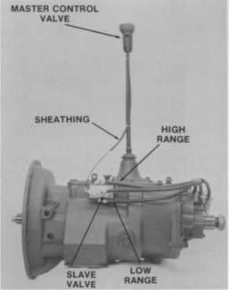
30 AIR SYSTEM MASTER CONTROL VALVE A-5010 NOTE: This valve provides range selection ONLY. When equipped on 15-Speed Models, the dash-mounted Deep Reduction Valve is required to provide deep reduction selections. Cut 6146 Removal and Disassembly Reassembly and Installation 1. Remove two screws holding bottom cover to valve 1. and slide cover down gear shift lever to expose air line fittings. Disconnect air lines Loosen jam nut and turn control valve from gear shift lever. 3. Pry medallion from recess in top cover. 4. Turn out the two screws to remove the top cover 3. from valve housing. Turn out the two screws in side of valve housing to separate the housing. Remove the Range Preelection Lever from left housing and the position balls and guide from lever. If necessary, remove spring and O-ring from bores in left housing. If necessary, remove springs, O-ring and sleeve from bores in right housing. 2. Refer to the drawing for proper reassembly. Use a VERY SMALL amount of silicone Iubricant on the O- rings to avoid clogging ports. A small amount of grease on the position springs and balls will help to hold them in place during reassembly. Reinstall control valve on gear shift lever and tighten jam nut. Attach air lines and reinstall bottom cover. 28
31 AIR SYSTEM DEEP REDUCTION AIR SYSTEM: LOW-LOW MODELS ONLY Operation In addition to the various components of the Range Shift Air System, the Deep Reduction Air System utilizes a reduction cylinder and a separate dashmounted Deep Reduction Valve OR the Master Control Valve A CONSTANT AIR from the air filter/regulator assembly is supplied to the reduction cylinder at the port on right side of cylinder cover. See Air System Schematics. With the Deep Reduction lever in the OUT position, the valve is OPENED and AIR is supplied to the Center Port of cylinder cover, moving the reduction piston forward to disengage deep reduction gearing. With the lever moved to the IN position, the valve is CLOSED and NO AIR is supplied to the Center Port. CONSTANT AIR from the air filter/regulator assembly moves the reduction piston rearward to engage reduction gearing. WHILE IN LOW RANGE, the button can be moved FORWARD to operate in DEEP REDUCTION. The SP Port of valve is OPENED when deep reduction selection is made, supplying AIR to the Center Port of cylinder cover. Button FORWARD ( SP Port OPENED) NOTE: WHILE IN HIGH RANGE, the mechanical interlock of Master Control Valve prevents movement of Deep Reduction Button to the FORWARD position. Lever to OUT (Valve OPENED) Lever to IN (Valve CLOSED) For models equipped with the Master Control Valve A-5015, AIR is supplied to the built-in deep reduction valve ONLY WHILE IN LOW RANGE from tee fitting at the Low Range or L Port of slave valve. The insert valve (see Page 33) MUST be installed in cylinder cover to provide the proper air flow needed to move the reduction piston in the cylinder. See schematic provided on Page 31. NOTE: The insert valve is NOT USED in the reduction cylinder cover of models equipped with the Deep Reduction Valve. With the Deep Reduction Button in the REARWARD position, the SP Port of control valve is CLOSED and NO AIR is supplied to the Center Port of cylinder cover. Button REARWARD ( SP Port CLOSED) Troubleshooting If the transmission fails to shift or shifts too slowly to or from DEEP REDUCTION, the fault may be in the Deep Reduction Air System or related components of the Range Shift Air System. To Iocate the trouble, the following checks should be made with normal vehicle air pressure supplied to the system, but with the engine off. See CAUTION, Page 24. NOTE: It is assumed that correct PSI readings were obtained from the air filter/regulator and all air lines have been checked for leaks. For Models Equipped with the Deep Reduction Valve Air Supply (See Air System Schematics.) With the gear shift lever in neutral, loosen the connection at the INLET (End Port) or Deep Reduction Valve until it can be determined that CONSTANT AIR is supplied to valve. Reconnect air line. If there is NO AIR, check for a restriction in line between the Deep Reduction Valve and slave valve, making sure this line is connected to tee fitting at the Supply or S Port of slave valve.
32 AIR SYSTEM 2. Deep Reduction Valve (See Air System 3. Reduction Cylinder (Refer to the following Schematics.) Illustration.) If any of {he seals in the reduction cylinder With the gear shift lever in neutral, disconnect the assembly are defective, the deep reduction shift air line leads from OUTLET of Deep Reduction will be affected. The degree of air lost will govern Valve. the degree of failure, from slow shifting to complete shift failure. A. WHILE IN LOW RANGE, move the Deep A. Reduction Valve Lever to the IN position. There should be NO AIR from disconnected line. B. B. Move the valve lever to the OUT position. There should now be CONSTANT AIR flowing from disconnected line. Return the valve Iever to the IN position to shut off air flow and reconnect air line. C. Leak at O-ring A results in a slow shift to engage deep reduction gearing; pressurizing of transmission case; deep reduction gearing can be disengaged. Leak at O-ring B results in slow shifting or complete failure to engage and disengage deep reduction gearing; steady flow of air from exhaust port of Deep Reduction Valve when lever is in the IN position. Leak at gasket C results in a slow shift to disengage deep reduction gearing; steady flow of air to atmosphere. REDUCTION CYLINDER ASSEMBLY (Models equipped with Deep Reduction Valve ONLY.)
 With the gear shift lever in neutral, select LOW RANGE and loosen the connection at the H Port of control valve until it can be determined that AIR is supplied to valve. Reconnect air line.")
33 AIR SYSTEM For Models Equipped with the Master Control Valve A Air Supply (See schematic below.) With the gear shift lever in neutral, select LOW RANGE and loosen the connection at the H Port of control valve until it can be determined that AIR is supplied to valve. Reconnect air line. If there is NO AIR, check for a restriction in the 1/8 O.D. air line between the control valve and slave valve, making sure this line is connected to tee fitting at the Low Range or L Port of slave valve. NOTE: Arrows are provided in this schematic to note direction of air flow through PRESSUR- IZED LINES SHOWN AS SHADED AREA ONLY.
34 AIR SYSTEM 2. Master Control Valve (See Page 34 and 4. Insert Valve (See next page.) schematic on preceding page.) Any constant flow of air from exhaust port of With the gear shift lever in neutral, disconnect the cylinder cover usually indicates a faulty insert 1/8 O.D. air line at the Center Port of reduction valve. Exhaust should occur ONLY BRIEFLY when cylinder cover, making sure this line Ieads from the Deep Reduction Button is moved FORWARD SP Port of control valve. WHILE IN LOW RANGE. A. WHILE IN LOW RANGE, move the Deep A faulty insert valve, leaking at the O-rings of Reduction Button FORWARD. There should be valve O.D. or from inner seals, will result in shift AIR flowing from disconnected line. Move the failure. Two indications of defective O-rings or button REARWARD to shut off air flow and seals are: reconnect air line. A. CONSTANT AIR flowing from exhaust port of B. If the preceding conditions did not exist, the cylinder cover. control valve is defective, or there is a B. CONSTANT AIR flowing from exhaust port E restriction in the air lines. of control valve WHILE DEEP REDUCTION 3. BUTTON IS REARWARD (providing the Reduction Cylinder (Refer to the following illustration.) control valve is operating properly). If any of the seals in the reduction cylinder The three O-rings in position on valve O.D can be assembly are defective, the deep reduction shift replaced. However, if an inner seal is damaged, the will be affected. The degree of air lost will govern complete assembly MUST be replaced. the degree of failure, from slow shifting to complete shift failure. A. Leak at O-ring A results in a slow shift to engage deep reduction gearing; pressurizing of transmission case; deep reduction gearing can be disengaged. B. Leak at O-ring B results in slow shifting or complete failure to engage and disengage deep reduction gearing; steady flow of air from exhaust port of control valve and/or cylinder cover when Deep Reduction Button is in the FORWARD position. C. Leak at gasket C results in a slow shift to disengage deep reduction gearing; steady flow of air to atmosphere. REDUCTION CYLINDER ASSEMBLY (Models equipped with Master Control A-5015 ONLY.)


.")

35 AIR SYSTEM Insert Valve: LL Models Equipped with Master Control Valve A-5015 The insert valve is a self-contained 1-3/16 valve Travel of the small insert valve piston is only 3/16. assembly located in the reduction cylinder cover. It As shown in the illustrations below, when NO AIR is CANNOT be disassembled except for the three O- applied to the top side of valve piston, CONSTANT AIR RINGS ON outer diameter. The O-rings provide a supplied from the regulator passes freely through the stationary seal and do not move in cylinder. insert valve and to the back side of cylinder piston, moving the yoke bar forward to disengage deep reduction gearing (LOW RANGE AND HIGH RANGE). When AIR is supplied to the top side of valve piston through signal line, the piston moves down to cutoff air CENTER PORT, supplied to the back side of cylinder piston. This air is SIGNAL LINE FROM exhausted out bottom port of cover when CONSTANT CONTROL VALVE AIR supplied from the regulator is directed to the front "SP PORT. side of cylinder piston, moving the yoke bar rearward to engage deep reduction gearing (LO/LO). INSERT VALVE RETAINING NUT BOTTOM EXHAUST PORT LO/LO When installing the insert valve in bottom bore of cover, apply Fuller #71206 silicone lubricant or its equivalent to O-rings and cylinder walls. Install valve in bore with flat surface to the inside. When installing the special valve retaining nut, apply Fuller #71204 adhesive/sealant or its equivalent to threads and tighten. See TORQUE RECOMMENDATIONS. AIR APPLIED THROUGH SIGNAL LINE PUSHES INSERT VALVE PISTON DOWN LOW RANGE AND HIGH RANGE NO AIR ON SIGNAL LINE CONSTANT AIR CONSTANT AIR SEALED OFF AT THIS POINT CONSTANT AIR TO BACK SIDE OF PISTON, YOKE BAR FORWARD AIR EXHAUST THROUGH BOTTOM PORT FROM BACK SIDE OF PISTON Cut 7450A
. Removal and Disassembly Reassembly and Installation 1. Remove two screws holding bottom cover to valve 1. Refer to the drawing for proper reassembly.")
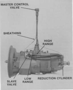
36 AIR SYSTEM MASTER CONTROL VALVE A-5015 NOTE: This valve provides BOTH range and deep reduction selection, replacing the need for separate units (Range Control Valve A-3546 or Master Control Valve A-5010 with dash-mounted Deep Reduction Valve). Removal and Disassembly Reassembly and Installation 1. Remove two screws holding bottom cover to valve 1. Refer to the drawing for proper reassembly. Use a and slide cover down gearshift lever to expose air line fittings. Disconnect air lines. VERY SMALL amount of silicone lubricant on the O- rings to avoid clogging ports. A small amount of 2. grease on the position springs and balls will help to Loosen jam nut and turn control valve from gear shift hold them in place during reassembly. lever. 3. Pry medallion from recess in top cover. 2. Reinstall control valve on gear shift lever and tighten jam nut. 4. Turn out the two screws to remove the top cover from valve housing, 3. Attach air lines and reinstall bottom cover. 5. Remove the actuator button from valve housing and the spring retainer, springs, seal and detent parts from actuator and/or valve housing. 6. Turn out the two screws in side of valve housing to separate the housing. 7. Remove the Range Preelection Lever from left housing and the position balls and guide from lever. 8. If necessary, remove springs, O-ring and retainer from bores in right housing.
37 7L: 8: 9: and 10 Speed (2-Speed Auxiliary) Range LO A-3546 Range Valve Down OR A-5010 Roadranger Valve Down Slave Valve Identification A-4688 Valve Outlet A-5000 Valve P S P S Valve A-4688 Slave Valve or A-5000 Slave Valve S P OR HI S P HI LO LO Schematic Air Filter/Regulator Assembly Range Cylinder Assembly LO Air to Housing Port For all questions concerning removal and replacement, refer to Eaton Service and Parts Literature. Air from Vehicle Source No Air Constant Air HI
38 7L: 8: 9: and 10 Speed (2-Speed Auxiliary) Range HI A-3546 Range Valve Up Outlet OR A-5010 Roadranger Valve Up Slave Valve Identification A-4688 Valve A-5000 Valve P S P S Valve A-4688 Slave Valve or A-5000 Slave Valve S P OR HI S P Schematic HI LO LO For all questions concerning removal and replacement, refer to Eaton Service and Parts Literature. Air Filter/Regulator Assembly Range Cylinder Assembly LO No Air Air from Vehicle Source Air to Cover Port Constant Air HI
39 RT, RTO, & RTX XX607LL: XX608LL: and XX615 Models Deep Reduction A-3546 Range Valve Down Outlet OR A-5010 Roadranger Valve Down Slave Valve Identification A-4688 Valve A-5000 Valve P S P S Valve A-4688 Slave Valve or A-5000 Slave Valve R S P OR R HI Schematic HI LO S LO P For all questions concerning removal and replacement, refer to Eaton Service and Parts Literature. Air Filter/Regulator Assembly Air from Vehicle Source Deep Reduction Valve DE E OUT P REDUCT SHIFT ONLY WHEN IN LOW RANGE DO NOT PRE-SELECT R Reduction Cylinder Assembly Constant Air ION IN In No Air Range Cylinder Assembly LO No Air Air to Housing Port HI
40 RT, RTO, & RTX XX607LL: XX608LL: and XX615 Models Range LO A-3546 Range Valve Down Outlet OR A-5010 Roadranger Valve Down Slave Valve Identification A-4688 Valve A-5000 Valve P S P S Valve A-4688 Slave Valve or A-5000 Slave Valve R S P OR R HI HI LO S LO P Schematic Air Filter/Regulator Assembly Air from Vehicle Source Deep Reduction Valve E DE P REDUCT SHIFT ONLY WHEN IN LOW OUT RANGE IN DO NOT PRE-SELECT R Reduction Cylinder Assembly Constant Air ION Out Range Cylinder Assembly LO No Air Air to Housing Port For all questions concerning removal and replacement, refer to Eaton Service and Parts Literature. HI
41 RT, RTO, & RTX XX607LL: XX608LL: and XX615 Models Range HI A-3546 Range Valve Up Outlet OR A-5010 Roadranger Valve Up Slave Valve Identification A-4688 Valve A-5000 Valve P S P S Valve A-4688 Slave Valve or A-5000 Slave Valve R S P OR R HI Schematic HI LO S LO P For all questions concerning removal and replacement, refer to Eaton Service and Parts Literature. Air Filter/Regulator Assembly Air from Vehicle Source Reduction Cylinder Assembly Constant Air Deep Reduction Valve E DE OUT P REDUCT SHIFT ONLY WHEN IN LOW RANGE DO NOT PRE-SELECT ION IN R Out Range Cylinder Assembly LO Air to Cover Port No Air HI
 NOTE: The example shown in this sequence uses an A-5010 master control valve and a #19470 slave valve.")

42 DISASSEMBLY AND REASSEMBLY SHIFTING CONTROLS RANGE SHIFT AIR SYSTEM A. To Remove the Range Shift Control Valve. (RTO-11607L) NOTE: The example shown in this sequence uses an A-5010 master control valve and a #19470 slave valve. Disassembly is similar for units equipped with different control and slave valve combinations. disconnect the nylon air lines at the master control valve. 1. Slide the shroud off the master control and 2. Disconnect the two nylon air lines at slave valve on transmission.


43 DISASSEMBLY AND REASSEMBLY SHIFTING CONTROLS C. To Remove the Slave Valve Assembly 3. B. Remove the master control valve, shroud and nylon air lines from the shift lever. To Remove the Air Regulator and Filter Assembly 1. Remove the two air lines between the slave valve and range cylinder. 1. Disconnect and remove the air line between the slave valve and air regulator. 2. Remove street ell and reducer from regulator if necessary. 2. Turn out the four capscrews and remove the slave valve from the transmission. Remove the sleeve from the slave valve. 3. Turn out capscrews and remove the air regulator and filter assembly from transmission.

44 DISASSEMBLY AND REASSEMBLY SHIFTING CONTROLS 3. If necessary, remove fittings from slave valves. 4. Remove the actuating spring and pin from bore in transmission.
45 DISASSEMBLY AND REASSEMBLY SHIFTING CONTROLS RANGE SHIFT AIR SYSTEM A. Remove the Range Shift Control Valve (RTO-11607LL) NOTE: The example shown in this sequence uses an A-5015 Master Control Valve, a Deep Reduction Cylinder and an A-4688 Slave Valve. master control and disconnect the nylon air lines at the master control valve. 1. Remove retaining screws, slide the shroud off the 2. Disconnect the three nylon air lines at the slave valve.


46 DISASSEMBLY AND REASSEMBLY SHIFTING CONTROLS B. To Remove Air Regulator and Filter Assembly 3. Disconnect the nylon air line at the deep reduction cylinder. 1. Remove the air line between the air regulator and the deep reduction cylinder. 4. Remove the master control valve, shroud and nylon air lines from the shift lever. 2. Remove the air line running from the air regulator to the slave valve at the regulator.


47 DISASSEMBLY AND REASSEMBLY SHIFTING CONTROLS 3. Turn out capscrews and remove the air regulator 2. Disconnect the two air lines running between the and filter assembly from transmission. slave valve and the range cylinder, at the range cylinder. C. To Remove the Slave Valve 1. Remove the hose clamp holding the air lines to the auxiliary. 3. Turn out the four capscrews and remove the slave valve from the transmission.


48 DISASSEMBLY AND REASSEMBLY SHIFTING CONTROLS 4. Remove the hat type sleeve from the bore in the slave valve. 5. Remove the actuating spring and pin from bore in transmission.
49 DISASSEMBLY AND REASSEMBLY SHIFTING CONTROLS GEAR SHIFT LEVER HOUSING


50 DISASSEMBLY AND REASSEMBLY SHIFTING CONTROLS A. Removal and Disassembly B Reassembly and Installation Install the spade pin in the bore in the housing. If previously removed, install the O-ring in the groove. Install the gear shift lever in the housing, fitting the slot in the lever ball over the spade pin. Place the tension spring washer over the lever ball with the dished side up. 1. Turn out the capscrews, jar lightly to break the gasket seal and remove the gear shift lever housing from the shift bar housing. 4. Seat the tension spring under the lugs in the housing, seating one coil at a time. Use of a spring driving tool is recommended. 2. Secure the housing in a vise and use a large screwdriver to twist between the spring and side of the housing, forcing the spring from under the three lugs. Do one coil at a time. Remove the spring. 3. Remove the washer and gear shift Iever. 4. Remove the spade pin from the bore in the housing. If necessary, remove the O-ring from the housing. 5. Make sure that the three tension springs and balls are in the shift bar housing bores and install the gear shift lever housing and gasket on the shift bar housing.

51 DISASSEMBLY AND REASSEMBLY SHIFTING CONTROLS SHIFT BAR HOUSING ASSEMBLY A. Removal and Disassembly Shift Bar Housing 1. Remove the capscrews from the shift bar housing. 2. Jar the housing to break the gasket seal, and Iift the housing up and off.


52 DISASSEMBLY AND REASSEMBLY SHIFTING CONTROLS 3. Tilt the housing, and remove the three tension balls 5. Remove the capscrews from all shift yokes and and springs. blocks. 4. Place housing in a vice with plunger side up and cut lock wire from all capscrews. 6. Slide the direct shift rail out of yokes and the housing. NOTE: Rails not being removed must be in the neutral position.


53 DISASSEMBLY AND REASSEMBLY SHIFTING CONTROLS 7. Remove center rail, yoke and block, being careful to remove the neutral interlock pin from the rail. 9. Remove reverse rail and yoke. 8. Remove air system interlock plunger. 10. Remove the two interlock balls from the front web.

54 DISASSEMBLY AND REASSEMBLY SHIFTING CONTROLS 11. Clamp the reverse yoke in a soft jawed vice and remove the snap ring from the reverse yoke plunger. 12. Remove the retainer, springs and plunger from the bore.


55 DISASSEMBLY AND REASSEMBLY SHIFTING CONTROLS SHIFT BAR HOUSING ASSEMBLY A. To Reassemble Shift Bar Housing 1. Coat the reverse yoke plunger lightly with oil, and install in bore. 3. Install the hat shaped retainer in the bore with the crown to the outside. 2. Install the springs in the bore, with the smaller 4. Install the retaining snap ring. diameter spring inside the larger. 5. Check the plunger for smooth operation by pushing it down into the bore several times and checking for free return.


56 DISASSEMBLY AND REASSEMBLY SHIFTING CONTROLS 6. Install the reverse rail through the reverse yoke, with the neutral notches to the rear. 8. Drop first interlock ball into web. 7. Line up the hole in the rail with the hole in the yoke and install capscrew. CAUTION: Do not torque capscrews beyond 45 ft. lbs. or rails could be distorted. 9. Install range plunger in bore.


57 DISASSEMBLY AND REASSEMBLY SHIFTING CONTROLS 10. Put reverse rail in neutral and start center rail partially in, installing center block with tapped hole toward the rear. 12. The shorter capscrew with the beveled head must be installed in the center block. 11. Install center yoke, and before pushing the rail completely in, install the interlock pin. 13. Drop the second ball in the web.

58 DISASSEMBLY AND REASSEMBLY SHIFTING CONTROLS 14. With the center and reverse rails in the neutral position, install the direct rail through the block and yoke. 15. Install all capscrews and lockwire. 16. Check that the lockout feature is working by putting one rail in gear and attempting to move the other two rails out of the neutral position. They should not move.


59 REMOVAL - COMPANION FLANGE, AUXILIARY SECTION AND CLUTCH HOUSING COMPANION FLANGE, AUXILIARY SECTION AND CLUTCH HOUSING A. To Remove the Universal Joint Companion Flange or Yoke 1. Lock the transmission by engaging two gears with 2. Use a large breaker bar to turn output shaft nut the mainshaft sliding clutches. from the output shaft


60 REMOVAL - COMPANION FLANGE, AUXILIARY SECTION AND CLUTCH HOUSING B. To Remove the Auxiliary Section from Transmission 3. Pull the companion flange or yoke from splines of output shaft. 1. Turn out the capscrews that attach the two sections. 2. Insert three puller screws in the tapped holes of housing flange. 4. Remove the speedometer drive gear or replacement spacer from hub of flange/yoke or from inside rear bearing cover remaining on output shaft (inset). For some models, it is necessary to remove the snap ring in groove of output shaft PRIOR to removal of the speedometer gear or spacer. NOTE: Temporarily reinstall output shaft nut to protect the threads during auxiliary removal. 3. Tighten puller screws evenly to move auxiliary section to the rear and just far enough from front section to break gasket seal.


61 REMOVAL - COMPANION FLANGE, AUXILIARY SECTION AND CLUTCH HOUSING Attach lifting eye to auxiliary and hook a hoist into position before sliding auxiliary section completely off dowels. Remove the gasket from the front section. 3. Jar clutch housing with a rubber mallet to break gasket seal and pull from transmission case. Remove gasket. C. 1. Removal of Clutch Housing For models so equipped, remove the clutch release mechanism and/or clutch brake assembly. See OPTIONS. 2. Turn out the four capscrews and remove the six nuts and lockwashers from studs securing the clutch housing to transmission case.
 A.")


62 DISASSEMBLY - AUXILIARY SECTION AUXILIARY SECTION (LOW) A. To Remove The Auxiliary Countershaft Assemblies 1. Remove countershaft bearing covers and the range 2. Remove the countershaft snap ring. cylinder cover.


63 DISASSEMBLY Ñ - AUXILIARY SECTION 3. Remove the locknut holding the range piston in the housing. 5. Remove the capscrews from the shift yoke. 4. Cut the lockwire from the shift yoke capscrews. 6. Slide the yoke bar back slightly to provide clearance and lift out the shift yoke.


64 DISASSEMBLY - AUXILIARY SECTION 7. Remove the piston from the yoke bar. 9. Drive the countershaft assemblies out through the countershaft bearings using a soft bar and maul. NOTE: Support the countershaft on the input side to prevent them from dropping. 10. If necessary, secure the assembly in a vise and remove the bearing inner race from front of countershaft with jaw pullers. NOTE: The vise used should be equipped with brass jaws or wood blocks to prevent damage to the countershaft. 8. Pull the yoke bar out the input side of housing.


65 DISASSEMBLY - AUXILIARY SECTION REAR HOUSING ASSEMBLY Cut /80 B. To Remove the Synchronizer Assembly, Mainshaft Assembly and Range Shift Air Cylinder 1. Slide the synchronizer assembly off the mainshaft. 2. Drive the mainshaft assembly out using a soft bar and maul. NOTE: Support the gear while driving.


66 DISASSEMBLY - AUXILIARY SECTION 3. Remove the rear bearing cover and the outer roller bearing. 5. Remove the range cylinder housing. 4. Tap out bearing cups and spacer using a soft punch. 6. Remove the O-Ring from the small bore in the housing if it is damaged or needs replacement.

67 DISASSEMBLY - AUXILIARY SECTION 7. Remove the countershaft bearings with a flat driver and a maul.


68 DISASSEMBLY - AUXILIARY SECTION I Cut /80 C. Mainshaft Disassembly 1. Remove the bearing inner spacer from the mainshaft. 2. Press the inner bearing from the mainshaft. CAUTION: Support the mainshaft from below so it does not drop and sustain damage during the pressing operation.
69 DISASSEMBLY - AUXILIARY SECTION 3. Remove the spline washer from the hub of low speed gear.


70 DISASSEMBLY - AUXILIARY SECTION SYNCHRONIZER ASSEMBLY Cut D. Synchronizer Disassembly 1. Pull upward to remove the high range synchronizer from pins. 2. Remove the sliding clutch from low range synchronizer pins. CAUTION: There are three springs which will be released as the high range synchronizer is removed from the pins. Cover the assembly with a rag to prevent losing springs.


71 REASSEMBLY - AUXILIARY SECTION AUXILIARY SECTION (LOW) A. Mainshaft Reassembly 1. Mark two adjacent gear teeth, and two teeth 180 from the first two teeth for timing purposes. IMPORTANT! There should be the same number of teeth between the markings on each side of the gear. 3. Install low speed gear on mainshaft with clutching teeth down. 2. Place the spline spacer in hub of low speed gear, shoulder toward rear. 4. Install the spacer washer with chamfer side up.


72 REASSEMBLY - AUXILIARY SECTION B. Mainshaft Installation 5. Heat the rear bearing in oil to 50 o F and drop down into position on mainshaft. CAUTION: Use asbestos gloves when handling heated bearings. 1. Install the outer bearing races and spacer into the housing. Make certain the lip on the outer race seats against the housing. 6. Install the inner race spacer above the bearing on the mainshaft. 2. Position the mainshaft and gear assembly in the housing. 3. Heat the outer bearing in oil to 250 o F. Slide the bearing into position and hold in place until it cools and seats on the shaft.

 in this hole. 1.")
 down over the pins on the synchronizer. 6.")
73 REASSEMBLY - AUXILIARY SECTION 4. If previously removed, install the oil seal in rear bearing cover, lip of seal to the rear. The spring in the seal should be toward the inside of the transmission. C. Synchronizer Reassembly 5. Locate the unshielded capscrew hole in the rear bearing cover, and install the capscrew with the brass washer (or brass washer and plastic sleeve, depending on model) in this hole. 1. Place the larger low range synchronizer face down on the bench with pins up. Install the sliding clutch (recessed side up) down over the pins on the synchronizer. 6. Bolt the cover into place using a new gasket. 2. Install the three springs into their bores. NOTE: The cover may be rotated 180 o for proper speedometer opening location.


74 REASSEMBLY - AUXILIARY SECTION D. Synchronizer Installation 3. Position the high range synchronizer ring so that the springs contact the side of the low speed synchronizer pins. Seat the ring by pushing down and twisting counterclockwise to compress springs. 1. Position the synchronizer in the low range position, and slide the assembly onto the mainshaft.


75 REASSEMBLY - AUXILIARY SECTION E. Countershaft Installation Seat the bearings part way in the bores with a soft mallet. If previously removed, install the bearing inner race on front of each countershaft. 4. Mesh the marked tooth on each countershaft with the marked teeth on the mainshaft gear, and slide the countershaft into position. 3. Locate gear tooth on both countershaft with "O" stamp and mark for timing. 5. Drive the countershaft bearings into the housing with a stepped driver and maul, until both bearings are fully seated on the shoulder in housing.


76 REASSEMBLY - AUXILIARY SECTION 6. With a soft bar and maul, drive the countershafts to the rear to expose snap ring grooves in countershaft. NOTE: It will be necessary to temporarily install the bearing covers to hold the countershaft bearings in place during this operation. 8. Reinstall the rear bearing covers using new gaskets. 7. Install the snap rings. F. Range Cylinder Installation 1. Bolt the cylinder housing into place using a new gasket. NOTE: The air port should be located in the 10 o'clock position.


77 REASSEMBLY - AUXILIARY SECTION 2. If previously removed, lubricate the O-ring and install in the small bore in the cylinder. 5. Install O-rings on OD and ID of piston and apply a light coat of silicone lubricant to the O-rings, 3. Position the shift yoke, and slide the yoke bar through the shift yoke and into the cylinder body from the input side. 6. Install the piston in the housing with the stepped face to the inside. 4. Install the yoke capscrews and lock with safety wire. 7. Install a new locknut on the yoke bar to secure the piston.

78 REASSEMBLY - AUXILIARY SECTION 8. Install the cylinder cover using a new gasket. NOTE: The air port opening should be located at the 11 o'clock position.


79 DISASSEMBLY - AUXILIARY SECTION AUXILIARY SECTION (LOW - LOW) A. Countershaft Removal 1. Remove the countershaft bearing covers. 2. Remove the range cylinder cover.


80 DISASSEMBLY - AUXILIARY SECTION 3. Remove the locking nut from the range yoke shaft and discard. 5. Remove the snap rings from the countershaft bearings. 4. Remove the reduction cylinder cover. 6. Cut the lockwire and remove capscrews.


81 DISASSEMBLY - AUXILIARY SECTION 7. Slide the yoke bar part way into the range cylinder housing to allow clearance for the shift yoke to be lifted out. 9. Drive out countershaft using a soft-bar and maul. CAUTION: Support the countershaft from the gear side to prevent them from dropping. 10. If necessary, secure the assembly in a vise and remove the bearing inner race from front of countershaft with jaw pullers. NOTE: The vise used should be equipped with brass jaws or wood blocks to prevent damage to the countershaft. 8. Remove piston from yoke bar, and slide yoke bar out from gear side of housing.


82 DISASSEMBLY - AUXILIARY SECTION B. Synchronizer and Low Range Gear Removal 1. Slide the synchronizer from the mainshaft. 3. Turn the tolerance washer to line up the splines and slide the low range gear off the mainshaft. 2. Remove the square key from the range mainshaft. 4. Remove spacer from inside low range gear.


83 DISASSEMBLY - AUXILIARY SECTION 5. Slide the coupler off mainshaft. 6. Remove the snap ring from the mainshaft.


84 DISASSEMBLY - AUXILIARY SECTION C. Reduction and Range Cylinder Removal 1. Cut lockwire and remove capscrew from reduction cylinder yoke. 2. Slide yoke and reduction clutch forward off mainshaft.


85 DISASSEMBLY - AUXILIARY SECTION 3. Remove the reduction cylinder body and yoke bar. 4. Remove the range cylinder body by removing capscrews.


86 DISASSEMBLY - AUXILIARY SECTION D. Mainshaft Removal 1. Remove C-ring from end of quill, 2. Pry range mainshaft off output shaft quill with two large screwdrivers. NOTE: Bearing can be removed from range mainshaft if replacement is necessary.

 off output shaft. 6.")


87 DISASSEMBLY - AUXILIARY SECTION 3. Remove rear bearing cover. 5. Slide speedospacer (or gear, depending on model) off output shaft. 6. Temporarily reinstall rear bearing cover. 4. Remove snap ring from output shaft. 7. Drive the output shaft out through the bearing with a soft bar and maul. 8. Remove rear bearing cover.


88 DISASSEMBLY - AUXILIARY SECTION 9. Remove the spacer and two outer races from bore. 10. Drive out the two countershaft bearings. CAUTION: The bearing is a matched set. If one piece of the bearing is damaged, the whole set must be replaced.


89 DISASSEMBLY - AUXILIARY SECTION E. Mainshaft Disassembly 3. Remove the washer from inside the deep reduction gear. 1. Press the inner bearing and deep reduction gear off the mainshaft. 2. Remove the spacer and oil retention ring from the deep reduction gear.
90 DISASSEMBLY - AUXILIARY SECTION F. Reduction Cylinder Insert Valve Disassembly 1. Remove the nut from the reduction cylinder cover. 2. Remove the insert valve from the cover. 3. Check the orifices in the valve for obstructions, and check the O-rings for damage. Replace any damaged or questionable O-rings.
.")


91 REASSEMBLY - AUXILIARY SECTION AUXILIARY SECTION (LOW - LOW). Cut /81 A. Mainshaft Reassembly 1. Use a driver to install range mainshaft and bearing 2. Use a "O" ring driver to install the C-ring on the on quill. nose of the quill.


92 REASSEMBLY - AUXILIARY SECTION 3. Mark two sets of gear teeth at a point 180 degrees apart for timing purposes. 4. Turn the mainshaft assembly over in the vise, and drop the externally splined washer down on the shaft. 6. Install the rear spacer with the machined surface riding on the machined surface of the gear. 5. Install the reduction gear on the mainshaft with conical clutching teeth facing down.


93 REASSEMBLY - AUXILIARY SECTION B. Main Shaft Installation 1. Install the oil deflector in the rear housing bore with the cupped surface facing up. Use a large bearing driver to drive the deflector down until the top surface of the deflector is 2" below the machined surface of the output shaft bore. NOTE: If available, use two bearing outer spacers stacked on top of each other to drive the oil deflector into the bore. The deflector will beat the proper depth when the top of the top spacer is flush with the machined surface of the output shaft bore. 3. Heat the inner bearing in oil to 250 o F and lower into place. CAUTION: Use asbestos gloves when handling heated bearings. 4. Install the bearing inner spacer on the shaft and against the front bearing cone. 2. Install the rear housing over the output shaft, allowing the housing to rest on the reduction gear.


94 REASSEMBLY - AUXILIARY SECTION 5. Stack the two bearing cups and outer spacer in the output shaft bore in the proper sequence. Make sure that the front bearing cup taper matches the taper direction of the front bearing cone. 8. Put speedo spacer (or drive gear) into place on shaft and install snap ring. Reposition housing in vise. 9. Tap the end of the output drive shaft with a soft bar and maul to make certain the mainshaft and bearings are seated Tap the two cups and outer spacer lightly and evenly into the case bore until the Iip of the rear cup seats against the machined surface. It will be necessary to block under the rear housing slightly to permit the output shaft assembly to move far enough. Heat and install the rear bearing cone on the shaft and in the rear cup, taper facing down. 10. Install the rear bearing cover using a new gasket and positioning the speedo drive gear bore at either the 10 o'clock or 3 o'clock position. NOTE: The capscrew with the brass washer must be installed in the unshielded capscrew hole using a new plastic collar.


95 REASSEMBLY - AUXILIARY SECTION C. Reduction Cylinder Assembly 1. Replace inner O-ring on reduction cylinder and external O-ring on reduction yoke bar. Lube both O-rings with silicone lube and install yoke bar in cylinder, 3. Install the insert valve into the cover with the tip pointing out. 2. Lube the O-rings on the insert valve with silicone lubricant. 4. Reinstall the insert valve retaining nut.


96 REASSEMBLY - AUXILIARY SECTION D. Low Range Gear Installation 5. Line up air hole in reduction cylinder body with hole in cover. Install a new gasket and match up the holes. 6. Install the reduction cylinder using a new gasket. Position the cylinder so the insert valve is at 6 oõclock. 1. Slide the low-low clutch part way onto the mainshaft, with the splined side toward the reduction gear. 2. Mesh the shift yoke with the clutch and slide back onto yoke bar.


97 REASSEMBLY - AUXILIARY SECTION 3. Install yoke capscrew and lockwire into place. 6. Install low range gear on mainshaft with machined surface facing machined surface on coupler. 4. Install snap ring on mainshaft. 7. Install the spacer-tolerance washer with beveled teeth facing out, and mesh it inside the low range gear. NOTE: Splined washers with varying thicknesses are available. Use the washer that provides the tightest fit in the hub of the gear. 5. Install coupler, with clutching teeth to rear.


98 REASSEMBLY - AUXILIARY SECTION E. Countershaft Installation 1. If previously removed, install the bearing inner race on front of each countershaft. 8. Rotate the spacer-tolerance washer to line up the square notch in the washer with the keyway in the range mainshaft. Install the key in the keyway, shoulder to rear. 9. If the synchronizer was disassembled, rebuild as detailed in low range auxiliary section. 2. Locate the stamped "O" on each countershaft gear. Mark the gear tooth directly above the "O" for timing purposes. 10. Slide the synchronizer into position on the mainshaft. 3. Install the countershaft bearings with a flanged driver.


99 REASSEMBLY - AUXILIARY SECTION 4. Mesh the marked tooth on each countershaft with the marked teeth on the reduction gear. 5. Drive the countershaft bearings fully into place in the housing. 7. When the snap ring grooves are fully exposed, install the snap rings. 6. Temporarily install the countershaft bearing covers and use a soft bar and maul to drive the countershaft back into the bearing. 8. Install the bearing covers with new gaskets.


100 REASSEMBLY - AUXILIARY SECTION F. Range Air System Installation 1. Install range shift air cylinder body. 2. If previously removed, install the O-ring in bore of range cylinder body. 3. Position the range yoke on the synchronizer. 5. Install the range yoke capscrews and lockwire. 4. Slide the range yoke bar through the range yoke and into the housing from the gear side. 6. Install range yoke piston with step to inside. Lube both internal and external O-rings with silicone before sliding into position.


101 REASSEMBLY - AUXILIARY SECTION 7. Install a new range yoke locking nut, torquing to 45 ft. lbs. 8. Install range cylinder cover with a new gasket.
 2. Engage two mainshaft sliding clutches into gear; this prevents transmission from rotating.")
102 DISASSEMBLY - FRONT SECTION A. To Remove Input Shaft Nut 1. Turn out the capscrews and remove the front bearing cover. (Tap input shaft to loosen bearing cover seal. ) 2. Engage two mainshaft sliding clutches into gear; this prevents transmission from rotating. Remove nut (left hand thread) with drive gear nut removing tool.


103 DISASSEMBLY - FRONT SECTION CASE ASSEMBLIES I *NOTE: Use lockwire at these positions during reassembly. Cut /80 B. Removal and Disassembly of Auxiliary Drive Gear Assembly 1. Cut the lockwire from the retainer plate capscrews and remove the capscrews 3. Insert the three puller screws into tapped holes of the retainer ring and tighten evenly to remove the drive gear assembly from the case bore. 2. Remove snap rings from the two counter shafts and the mainshaft.


104 DISASSEMBLY - FRONT SECTION 4. Remove the snap ring from hub of auxiliary drive gear. 6. If necessary, remove the O-rings from hub O.D. of auxiliary drive gear. 7. Remove the inner snap ring from the mainshaft. 5. Using the rear face of retainer ring as a base, press the drive gear through bearing.


105 DISASSEMBLY - FRONT SECTION C. Upper Reverse Idler Gear Assembly Removal 1. Remove the upper reverse idler gear assembly locknut and washer. 3. Remove the reverse idler shaft plug to allow the puller tool to be installed in the end of the shaft. 2. Pull the front auxiliary countershaft bearing with a flanged slide puller. 4. Install a threaded slide puller in the end of the shaft and pull the reverse idler shaft from the bore.


106 DISASSEMBLY - FRONT SECTION D. Upper Countershaft Assembly and Mainshaft Assembly Removal 5. Remove the snap ring from the inside of the reverse gear, allowing the gear to be slid forward on the mainshaft. 1. Remove the upper countershaft rear bearing by driving out with a soft bar and maul. NOTE: Bearing will be damaged during this operation. 6. Lift out upper reverse idler gear and washer. 2. Remove the snap ring from the upper countershaft front bearing.


107 DISASSEMBLY - FRONT SECTION 3. Drive the countershaft part way through the 6. bearing with a soft bar and maul. NOTE: Make certain that the reverse gear is up on the lower idler gear and is not hanging up during 7. this operation. Support the reverse gear with one thumb from behind while lifting upon the mainshaft at the front clutch. Support reverse gear on the auxiliary web, switch position of back hand and lift out mainshaft assembly. 4. When the shaft is almost through, go to the back 8. side and drive the shaft forward to remove the front bearing from the bore. Remove upper countershaft by sliding the shaft back, and tilting front up and out. 5. Remove bearing from shaft using bearing puller or pry bars, and remove upper countershaft toward case wall as far away from the mainshaft as possible.


108 DISASSEMBLY - FRONT SECTION E. Lower Countershaft, Lower Idler Assembly and Input Shaft Assembly Removal 3. Tap the input shaft bearing out the front of the case with a driver. 1. Drive the input shaft back through bearing with a soft bar and maul. 2. Lift input shaft and input drive gear from case. 4. Remove the lower countershaft. Steps for removal are identical to upper countershaft removal. NOTE: Make certain the countershaft are not mixed after removal. The upper countershaft has a 45 tooth PTO gear and the lower a 47 tooth PTO.

109 DISASSEMBLY - FRONT SECTION 5. Remove the lower reverse idler assembly. Steps for removal are identical to the upper idler assembly removal. 6. If any of the magnets in the bottom of the case were damaged during disassembly, chip them out and glue new magnets into place using Scotch Grip Rubber Adhesive or equivalent adhesive.


110 DISASSEMBLY - FRONT SECTION F. To Disassemble the Countershaft Assemblies NOTE: Both countershaft are disassembled in the same manner, as construction is identical. 1. Remove snap ring from front of countershaft. 2. Press the drive ear, PTO and overdrive gear off the countershaft in one cluster. NOTE: A press with a minimum of 20 tons will be necessary for this operation.


111 DISASSEMBLY - FRONT SECTION 3. Press off 2nd speed gear. 4. Press the 1st speed gear from the countershaft, 5. Remove the key and roll pin if replacement is necessary due to damage or excessive wear.


112 DISASSEMBLY - FRONT SECTION G. To Disassemble the Mainshaft Assembly 1. Remove the sliding clutch from the mainshaft. 3. Rotate the tolerance washer to line up splines, and remove washer, spacer, overdrive gear and second gear.. 2. Lift the short key out of the groove in the mainshaft. 4. Clamp the mainshaft in a vise with brass or soft jaws and withdraw the long key.


113 DISASSEMBLY - FRONT SECTION 5. Remove the spacer and tolerance washer from mainshaft. 7. Remove low gear with tolerance washer and spacer. 6. Remove reverse gear and reverse clutch. 8. Remove first gear with tolerance washer and spacer.

114 DISASSEMBLY - FRONT SECTION 9. Lift the final sliding clutch and tolerance washer from the mainshaft.

115 REASSEMBLY - FRONT SECTION A. Reassembly of the Countershaft Assemblies 1. If previously removed, install the roll pin and long key in keyway of countershaft. 3. Press the second speed gear on countershaft, long hub of gear against first speed gear hub. 2. Align keyway in gear with key in countershaft and press first speed gear into position on shaft, long hub of gear toward front of countershaft. 4. Press the overdrive gear on countershaft against second speed gear.
116 REASSEMBLY - FRONT SECTION 7. Reinstall the snap ring on the front of the countershaft. 5. Press the power take-off gear on the countershaft with the bullet nose teeth against the overdrive gear. 6. Press the drive gear on the countershaft with the long nub facing the PTO gear.


117 REASSEMBLY - FRONT SECTION B. To Reassemble the Mainshaft Assembly 1. Place the mainshaft in a brass or soft jawed vise with pilot end down. 2. Install a tolerance washer on the mainshaft with the step on the washer facing up. Rotate washer to locate in groove of mainshaft. NOTE: The stepped side of tolerance washers always faces a clutch. 4. Install a tolerance washer with the flat side up, rotate washer to locate in groove. Install a spacer. 5. Temporarily install the key. 3. Locate the missing spline in a clutch, and install over the groove with the roil pin at the bottom. 6. Install first gear with clutching teeth toward the clutch (flat machined surface facing up).


118 REASSEMBLY - FRONT SECTION Install low gear with the machined surface facing down toward first gear. Remove the key. 10. Rotate the tolerance washer to line up splines and install key. 9. Install a spacer and a tolerance washer with the stepped side of the tolerance washer facing up. 11. Check the clearance between low and first gear by lightly wedging the gears apart with two large screwdrivers and measuring the gap with a feeler gauge. The gap must be between.005" to.012".


119 REASSEMBLY - FRONT SECTION 12. Washers are available in the following thicknesses to obtain the correct limits Refer to Illustrated Parts Lists for washer part numbers. 16. Temporarily install the internal snap ring in the reverse gear, and install the reverse gear with the clutching teeth facing down. 13. Install a clutch with the missing internal spline of the clutch aligned over the key. 14. Temporarily remove the key and install the tolerance washer with the step down and a spacer. 17. Install the mainshaft snap ring. 15. Rotate the tolerance washer to line up splines and reinstall the key.

. 19.")
120 REASSEMBLY - FRONT SECTION NOTE: Because the auxiliary drive gear assembly is used in checking reverse gear axial clearance, it must be reassembled before continuing mainshaft reassembly. 18. If previously removed, install the O-rings on extended front hub of auxiliary drive gear. 20. Start the auxiliary drive gear bearing on front hub, bearing snap ring facing groove in retainer ring. Using both the inner and outer race of bearing as a base, press the bearing on gear with snap ring in groove of retainer ring or use a bearing driver (inset). 19. Install the retainer ring on auxiliary drive gear snap ring groove facing front hub and away from gear teeth. 21. Install the snap ring in groove of front gear hub to retain bearing.


121 REASSEMBLY - FRONT SECTION 22. Temporarily install the auxiliary drive gear on the mainshaft with the clutching teeth facing up. 23. Apply slight downward pressure on the auxiliary drive gear and reverse gear, and check the clearance between the two gears with a feeler gauge. 27. Remove the mainshaft from the vise and install with pilot end up. Install a spacer on the mainshaft. 24. Clearance can be adjusted by replacing reverse gear splined washer with a different thickness washer. Proper clearance at this location should be.005" to.012". 25. Remove the auxiliary drive gear and reverse gear. 26. Remove the internal snap ring from reverse gear. (This is necessary for mainshaft installation.) 28. Install second gear with the clutching teeth down. (Machined surface facing up.)


122 REASSEMBLY - FRONT SECTION 31. Install the short key in the keyway. 29. Install overdrive gear with the clutching teeth facing up. 30. Install a spacer in the overdrive gear. Install a tolerance washer with the stepped side facing up, aligning the square internal notch of the tolerance washer with the keyway in the mainshaft. 32. Check the clearance between the second and overdrive gears by placing two large screwdrivers between the gears. Apply light downward pressure on the screwdrivers, and measure the gap between the gears with a feeler gauge. 33. The clearance between the gears must be between.005" and.01 2". Adjust in the same manner as low and first gear.

")
123 REASSEMBLY - FRONT SECTION 34. Install the sliding clutch. 35. Remove the mainshaft assembly from the vise. 36. Install the reverse gear (without internal snap ring) and the mainshaft snap ring if previously removed.


124 REASSEMBLY - FRONT SECTION C. Lower Countershaft Installation 1. Before beginning installation, mark the gear tooth 3. Install the front bearing (snap ring to outside) into directly above the keyway on both countershaft the case and onto the countershaft using a flanged for timing purposes. This tooth will be identified by driver. an "O" that is stamped on the front of the tooth. 4. When the snap ring groove is fully exposed, install the snap ring on the countershaft. 2. Position the lower countershaft (47 tooth PTO gear) in the front section.


125 REASSEMBLY - FRONT SECTION 5. Position the rear countershaft bearing with the chamfered side of the inner race toward the inside D. Install the snap ring on the countershaft when the groove is fully exposed. Tap on the drive gear end of the countershaft with a soft bar and maul, to make certain both bearings are fully seated. Lower Reverse Idler Gear Installation 6. Drive the new rear bearing in with a flanged driver. 1. Press the inner needle bearing and race into the reverse idler gear, if they were removed.


126 REASSEMBLY - FRONT SECTION 2. Position the idler gear in the case with the long hub toward the front of the transmission. 5. Drive the shaft back into the boss with a soft bar and maul. 3. Start the shaft, with half moon washer installed, partway into the gear. 6. Install the washer and locknut on the shaft and tighten securely. Check the gear for free rotation after tightening nut. 4. Position the flat washer between the gear and boss, and install the shaft completely into the boss.


127 REASSEMBLY - FRONT SECTION E. Input Drive Gear Assembly Installation 7. Install the plug in the end of the shaft. 1. Paint any two adjacent teeth of the main drive gear and then paint the two teeth directly opposite. 2. Install the inner bushing in the input shaft if removed. 8. Install the auxiliary bearing with a driver until the bearing bottoms against idler shaft retainer, 3. Install the main drive gear (snap ring toward case) and input shaft, meshing the marked teeth with the marked tooth on the lower countershaft. 4. Slide the input shaft through the main drive gear.


128 REASSEMBLY - FRONT SECTION 5. Install spacer and bearing on shaft with external 8. Use a long bar and maul to drive the input shaft out snap ring to the outside. through the bearing from the inside of the case. 9. Remove the front bearing cover. NOTE: If a flanged driver of the correct length is available, it can be used to install the bearing. If the driver is unavailable, follow steps 6 through Tap the bearing into position in the bore with a soft mallet. 7. Temporarily install the front bearing cover.


129 REASSEMBLY - FRONT SECTION F. Mainshaft Assembly and Upper Countershaft Installation 1. Lower the upper countershaft assembly into position in the case. 4. Lower the mainshaft assembly into position, reverse end first. 2. Rotate the countershaft until the timing tooth is close to the marked teeth on the main drive gear. CAUTION: Support the reverse gear to prevent it from dropping and causing injury. 3. Pry the countershaft awayfrom the drive gear as far as possible with a large screwdriver. 5. Use a soft mallet to temporarily install the auxiliary drive gear assembly. Seat it part way into the bearing bore to hold the mainshaft in position. 6. Check to make sure the timing marks are still properly in mesh between the lower countershaft and the main drive gear.


130 REASSEMBLY - FRONT SECTION 10. Install the upper reverse idler gear assembly following the same sequence as used for the lower reverse idler. 7. Remove the screwdriver wedging the upper countershaft and rotate the countershaft until the timing tooth is meshed correctly with the drive gear timing teeth. 8. Install the front and rear countershaft bearings, following the same sequence used when installing the lower countershaft bearings. 11. Slide the reverse gear back into position and install the snap ring in the gear. 9. Remove the auxiliary drive gear assembly. Do not let the mainshaft move to the rear when removing auxiliary drive gear.


131 REASSEMBLY - FRONT SECTION G. Auxiliary Drive Gear Installation 1. Reinstall auxiliary drive gear assembly. 2. Install the capscrews holding the auxiliary drive gear to the case, and torque to specifications. 4. Install rear snap ring on mainshaft. 5. Check that the gear assemblies all spin freely, and engage all clutches to check that the unit is timed correctly. 3. Lockwire the capscrews.
132 REASSEMBLY - FRONT SECTION H. Drive Gear Nut and Bearing Cover Installation 1. Apply Ioctite grade 277 sealant and install a new drive gear nut and torque to lbs. ft. of torque using a drive gear nut installer. DO NOT REUSE OLD NUT. 3 Install the bearing cover using a new gasket and aligning the oil return slot in the cover with the hole in the case. 2. Stake the nut into the two milled slots of the input shaft with a staking tool or a punch and maul.


133 INSTALLATION - COMPANION FLANGE, AUXILIARY SECTION AND CLUTCH HOUSING A. Clutch Housing Installation B. Position the corresponding new gasket on housing mounting surface and install the clutch housing on front case, piloting on the six studs and drive gear bearing cover. Install the six nuts with washers or lockwashers on studs and tighten. See TORQUE RECOMMEN- DATIONS. Install the four capscrews with lockwashers and tighten. See TORQUE RECOMMENDATIONS. Auxiliary Section Installation 2. Slide the auxiliary part way onto the dowels, and remove the lifting eye. 3. Slide the auxiliary the rest of the way into position. It may make assembly easier if someone slowly rotates the input shaft during installation. 4. Fasten the auxiliary to the front section, drawing the capscrews down evenly. See TORQUE RECOMMENDATIONS. C. Companion Flange Installation 1. Install a new auxiliary mating surface gasket. Lower the auxiliary section into position with a hoist and align on the dowel pins. NOTE: When installing a low-low auxiliary, the deep reduction clutch must be moved to the rear, engaging the deep reduction gear. 1. Lock the transmission by engaging two gears with the mainshaft sliding clutches.


134 INSTALLATION - COMPANION FLANGE, AUXILIARY SECTION AND CLUTCH HOUSING 2. Slide the companion flange or yoke onto the output shaft. 3. Install the output shaft nut and washer, torqueing to ft. lbs.


135 INSTALLATION - SHIFTING CONTROLS SHIFT BAR HOUSING ASSEMBLY A. Installation 1. Make sure the shift bars are in the neutral position. 4. Install the shifting bar housing on transmission, fitting yokes into slots of corresponding clutch gears. 2. Place the sliding clutches on the mainshaft in the neutral position. 3. Install a new shift bar housing gasket in position on the case. 5. Install the attaching capscrews; tighten securely.


136 INSTALLATION - SHIFTING CONTROLS GEAR SHIFT LEVER HOUSING ASSEMBLY A. Installation 1. Make certain the three tension springs and balls are in the shift housing bores and install the gear shift lever housing and gasket on the shift bar housing, fitting the lever into shift block and yoke notches. 2. Install the four capscrews and tighten securely.


137 INSTALLATION - SHIFTING CONTROLS AIR SYSTEM - RTO-11607L A. Installation of Slave Valve NOTE: For air line routing on transmissions equipped with a different combination of control valve and slave valve, see air schematics on pages 35 to Install the actuating pin and spring in bore in transmission. 2. If previously removed, install the fittings on the slave valve. 4. Install the slave valve on transmission using a new gasket. Tighten capscrews evenly and securely. Actuating plunger in case fits into alignment sleeve in slave valve. B. Installation of Air Lines and Regulator 3. Make sure the alignment sleeve is installed in the slave valve. 1. Install the low range airline between the "L" port on the slave valve and the air port in the body of the range cylinder.

138 INSTALLATION - SHIFTING CONTROLS 2. Install the high range air line between the "H" port on slave valve and the air port in the cover of the range cylinder. 4. Install the air line between the air regulator and the "S" port of slave valve. C. Master Control Valve Installation Install the air regulator and filter assembly on mounting surface on the range cylinder cover; tighten capscrews securely. 1. Install the master control valve on the gear shift lever. 2. If air lines are to be replaced, measure lines and sheathing for correct length.


139 INSTALLATION - SHIFTING CONTROLS 3. Install sheathing on lines and draw under shroud on lever. 4. Connect the black nylon air line to the "S" port on 6. Install the white nylon air line from the "P" port of the master control valve, and the white nylon line to the control valve to the "P" port in the slave valve. the "P" port. 5. Install the black nylon air line from the "S" port of the control valve to the "S" port in the slave valve.

140 INSTALLATION - SHIFTING CONTROLS AIR SYSTEM - RTO-11607LL A. Installation of Slave Valve NOTE: For air line routing on transmissions equipped with a different combination of control valve and slave valve, see air schematics on pages 35 to B. Install the slave valve using a new gasket. Installation of Air Lines and Regulator 1. Install the actuating pin and spring in bore in transmission. 1. Install the air line from the low range port in the slave valve to the body of the range cylinder. 2. Install the hat type alignment sleeve in the slave valve. 2. Install the line from the high range port of the slave valve to the cover of the range cylinder.

141 INSTALLATION - SHIFTING CONTROLS 3. Install the air regulator and filter assembly on mounting surface on the range cylinder; tighten capscrews securely. 5. Install the air line from the slave valve to the reduction cylinder. 4. Install the air supply line from the slave valve to the air regulator. 6. Install the hose clamp that routes the air lines.


142 INSTALLATION - SHIFTING CONTROLS C. To Install the Master Control Valve 5. Install the nylon air line from the "H" port of the master control valve to the low range port of the slave valve Install the master control valve on the gear shift lever. If air lines are to be replaced, measure lines and sheathing for correct length. Install sheathing on lines and draw under shroud on lever. 6. Install the nylon air line from the "SP" port of the control valve to the reduction cylinder. 4. Connect the black nylon air line to the "S" port on the master control valve, and the white nylon line to the "P" port.
143

144 Copyright Eaton and Dana Corporation, EATON AND DANA CORPORA TION hereby grants its customer s, vendor s, or distributor s permission to freely copy, reproduce and/or distribute this document in printed format. It may be copied only in its entirety without any changes or modifications. THIS INFORMATION IS NOT INTENDED FOR SALE OR RESALE, AND THIS NOTICE MUST REMAIN ON ALL COPIES. For spec ing or service assistance, call HELP (4357) 24 hours a day, 7 days a week (Mexico: ), for mo re time on the road. O r visit our web sit e at ang er.com. Roadranger: Eaton, Dana and other trusted partner s providing the best products and services in the industry, ensuring more time on the road Eaton Corporation All rights reserved. Pr inted in US A Eaton Corporation Truck Components Operations P. O. Bo x 4013 Kalamaz oo, MI U.S.A.
Service Manual. Fuller Heavy Duty Transmissions TRSM0880 October 2007
 Service Manual Fuller Heavy Duty Transmissions TRSM0880 October 2007 For parts or service call us Pro Gear & Transmission, Inc. 1 (877) 776-4600 (407) 872-1901 parts@eprogear.com 906 W. Gore St. Orlando,
Fuller Heavy Duty Transmissions TRSM0660 October 2007
 Service Manual Fuller Heavy Duty Transmissions TRSM0660 October 2007 RTLO-14613B RTLOF-14613B TABLE OF CONTENTS FOREWORD............. MODEL DESIGNATIONS AND LUBRICATION............ OPERATION.............
Service Manual. Fuller Heavy Duty Transmissions
 Fuller Heavy Duty Transmissions More time on the road Service Manual Fuller Heavy Duty Transmissions TRSM0430 July 2010 RT-8608L RTF-8608L RTO-11608LL RTO-14608LL RTOF-11608LL RTOF-14608LL RTX-11608LL
Fuller Mid-Range Transmissions TRDR0100
 Driver Instructions Video Instruction Available Instructional videos are available for download at no charge at roadranger.com Videos are also available for purchase. To order, call 1-888-386-4636. Ask
Service Manual. Fuller Mechanical Transmissions TRSM0992 October 2007
 Service Manual Fuller Mechanical Transmissions TRSM0992 October 2007 Introduction Warnings and Precautions Before starting a vehicle always be seated in the driver s seat, place the transmission in neutral,
For the most current information, visit the Roadranger web site at
 Eaton Fuller Heavy Duty Transmissions 8 - Speed Direct Drivers Instructions TRDR-0310 March 2004 For the most current information, visit the Roadranger web site at www.roadranger.com Warnings Warnings
Service Manual. Fuller Heavy Duty Transmissions TRSM0515 October 2007
 Service Manual Fuller Heavy Duty Transmissions TRSM0515 October 2007 TABLE OF CONTENTS Timing Description Operations Lubrication Preventive Maintenance Torque Recommendations Air System Precautions Disassembly
Service Manual. Fuller Heavy Duty Transmissions TRSM0250 October 2007
 Service Manual Fuller Heavy Duty Transmissions TRSM0250 October 2007 TABLE OF CONTENTS FOREWORD........................................ MODEL DESIGNATIONS AND SPECIFICATIONS.......... LUBRICATION......................................
Service Manual. Fuller Medium Heavy Transmissions TRSM0201 October 2007
 Service Manual Fuller Medium Heavy Transmissions TRSM0201 October 2007 Model Designations...2 Description...3 Specifications...4 Lubrication...5 Conversion to Overdrive...6 Clutch Shaft Replacement...6
Eaton Fuller Heavy Duty Transmissions
 Eaton Fuller Heavy Duty Transmissions 13 Speed Models Driver Instructions TRDR-0630 May 2004 For the most current information, visit the Roadranger web site at www.roadranger.com General Information Warnings
Fuller Mid-Range Transmissions TRSM0160 October 2007
 Service Manual Fuller Mid-Range Transmissions TRSM0160 October 2007 FS-5106A FS-6206A Before starting a vehicle always be seated in the drivers seat, place the transmission in neutral, set the parking
Fuller Heavy Duty Transmissions TRSM0503 October 2007
 Service Manual Fuller Heavy Duty Transmissions TRSM0503 October 2007 RTX-12510 RTX-12515 RTXF-12510 RTXF-12515 Table of Contents Model Designations..............................3 Description....................................4
Fuller Heavy-Duty Transmissions TRSM1500 EN-US May 2017
 Service Manual Fuller Heavy-Duty Transmissions TRSM1500 EN-US May 2017 RT-8908LL RTO-11707LL RTO-11708LL RTOF-11707LL RTOF-11708LL RTOF-14708LL RTX-11708LL RTX-14708LL RTXF-11708LL RTXF-14708LL RTO-11707DLL
Transmission Overhaul Procedures-Bench Service
 How to Assemble the Lower Reverse Idler Gear Assembly Special Instructions In 1996 Eaton changed the reverse idler system design. In the nut design, the reverse idler bearing was lubricated through a hole
Fuller Automated Transmissions TRSM0020 October 2007
 Service Manual Fuller Automated Transmissions TRSM000 October 007 RT-09A-AT RT-09A-ATR RT-09A-ATS RT-09A-AT RT-409A-ATS RTO-09A-AT RTO-09A-ATS RTO-09B-AT RTO-09B-ATE RTO-09B-ATR RTO-09B-ATS RTO-09A-AT
Eaton Fuller Advantage Heavy-Duty Manual Transmissions TRSM0970 EN-US
 Service Manual Eaton Fuller Advantage Heavy-Duty Manual Transmissions TRSM0970 EN-US January 2016 FA(F)-9810B FA(F)-11810B FA(F)-12810B FA(F)-13810B FA(F)-14810B FA(F)-15810B FAO(F)-11810C FAO(F)-12810C
Transmission Overhaul Procedures-Bench Service
 How to Install the Auxiliary Countershaft Assembly Special Instructions To make auxiliary section assembly easier, you can make an auxiliary section fixture out of a 2" x 12" piece of wood. 3' 1' 3" 4.56"
Eaton Fuller Advantage Heavy-Duty Manual Transmissions TRDR0970 EN-US
 Driver Instructions Video Instruction Available Instructional videos are available for download at no charge at Roadranger.com Videos are also available for purchase. To order, call 1-888-386-4636. Ask
Fuller Heavy Duty Transmissions. Video Instruction Available. Fuller Heavy Duty Transmissions TRDR3349 September 2007
 Fuller Heavy Duty Transmissions More time on the road Video Instruction Available Instructional videos are available for download at no charge at roadranger.com Videos are also available in DVD format
Eaton 9-Speed Synchronized Transmissions Single H Shift Control Configuration TRDR0072
 Driver Instructions Eaton 9-Speed Synchronized Transmissions Single H Shift Control Configuration TRDR0072 February 2008 FS(O) 6109 FS(O) 6209 FS(O) 6309 FS(O) 8209 FS(O) 8309 FS(O) 10209 FS(O) 10309 Warnings
UltraShift PLUS Automated Transmissions TRSM0940 EN-US
 Service Manual UltraShift PLUS Automated Transmissions TRSM0940 EN-US April 2016 UltraShift PLUS Linehaul Active Shifting (LAS) UltraShift PLUS Vocational Active Shifting (VAS) UltraShift PLUS Multipurpose
Service Manual. Fuller Medium Heavy Transmissions TRSM0226 October 2007
 Service Manual Fuller Medium Heavy Transmissions TRSM0226 October 2007 RT-906 SERIES Twin Countershaft ROADRANGER Transmissions 6 forward speeds - 2 reverse speeds Six forward speeds are obtained with
Eaton Fuller Heavy-Duty Transmissions TRDR0670 EN-US
 Driver Instructions Video Instruction Available Instructional videos are available for download at no charge at roadranger.com Videos are also available for purchase. To order, call 1-888-386-4636. Ask
Valtek Auxiliary Handwheels and Limit Stops
 Valtek Auxiliary s and Limit Stops Table of Contents Page 1 General information 2 Installation 2 Side-mounted handwheels, size 25 and 50 (linear actuators) 3 Side-mounted handwheels, size 100 and 200 (linear
Eaton Fuller HD FR/FRO Transmissions TRSM2400 June 2011
 Service Manual Eaton Fuller HD FR/FRO Transmissions TRSM2400 June 2011 FR-11210B FR-12210B FR-13210B FR-14210B FR-15210B FR-9210B FRF-11210B FRF-12210B FRF-13210B FRF-14210B FRF-15210B FRF-9210B FRO-11210B
MANUAL TRANS OVERHAUL - BORG-WARNER - T56 6-SPEED MANUAL TRANSMISSIONS Borg-Warner T56 (MM6) 6-Speed
 6-Speed") IDENTIFICATION MANUAL TRANS OVERHAUL - BORG-WARNER - T56 6-SPEED 1998 MANUAL TRANSMISSIONS Borg-Warner T56 (MM6) 6-Speed Transmission has 2 identification labels, located on lower left side of case. One
IDENTIFICATION MANUAL TRANS OVERHAUL - BORG-WARNER - T56 6-SPEED 1998 MANUAL TRANSMISSIONS Borg-Warner T56 (MM6) 6-Speed Transmission has 2 identification labels, located on lower left side of case. One
TRANSMISSION AND TRANSFER CASE
 DR TRANSMISSION AND TRANSFER CASE 21-1 TRANSMISSION AND TRANSFER CASE TABLE OF CONTENTS page MANUAL TRANSMISSION- G56- SERVICE INFORMATION...1 MANUAL TRANSMISSION- GETRAG 238- SERVICEINFORMATION...69 MANUAL
Maintenance Instructions
 General Note These instructions contain information common to more than one model of Bevel Gear Drive. To simplify reading, similar models have been grouped as follows: GROUP 1 Models 11, 0, 1,, (illustrated),,
Telephone (925) Fax (925) Lawrence Drive,Livermore, California
 Fax (925) Lawrence Drive,Livermore, California") Telephone (925) 454-9500 Fax (925) 454-9501 151 Lawrence Drive,Livermore, California 94551 www.fabcoautomotive.com Fabco Automotive Corporation Transfer Case Service Manual Model TC-33 625 320 Copyright
Telephone (925) 454-9500 Fax (925) 454-9501 151 Lawrence Drive,Livermore, California 94551 www.fabcoautomotive.com Fabco Automotive Corporation Transfer Case Service Manual Model TC-33 625 320 Copyright
MANUAL TRANSAXLE Return to Main Table of Contents
 MANUAL TRANSAXLE Return to Main Table of Contents GENERAL... 2 MANUAL TRANSAXLE CONTROL... 12 SHIFT LEVER ASSEMBLY... 14 MANUAL TRANSAXLE... 15 MANUAL TRANSAXLE ASSEMBLY... 17 FIFTH SPEED SYNCHRONIZER
TRANSMISSION AND TRANSFER CASE
 TJ TRANSMISSION AND TRANSFER CASE 21-1 TRANSMISSION AND TRANSFER CASE TABLE OF CONTENTS page MANUAL TRANSMISSION - NSG370...1 AUTOMATIC TRANSMISSION - 42RLE...37 page TRANSFER CASE - NV231...165 TRANSFER
Driver Instructions. Fuller Heavy Duty Transmissions. Video Instruction Available. Fuller Heavy Duty Transmissions TRDR0550 September 2007
 Fuller Heavy Duty Transmissions More time on the road Video Instruction Available Instructional videos are available for download at no charge at roadranger.com Videos are also available in DVD format
SPECIAL TOOLS Dodge Pickup 5.9L Eng R3500. Fig 1: Identifying Remover C-3985-B (Special Tool) 9/6/13 Printer Friendly View
 9/6/13 Printer Friendly View") Procedures 2003 Dodge Pickup 5.9L Eng R3500 manual transmission SPECIAL TOOLS Fig 1: Identifying Remover C-3985-B (Special Tool) www2.prodemand.com/print/index?content=tabs&module=true&tab=true&terms=true&ymms=false&classname=
Procedures 2003 Dodge Pickup 5.9L Eng R3500 manual transmission SPECIAL TOOLS Fig 1: Identifying Remover C-3985-B (Special Tool) www2.prodemand.com/print/index?content=tabs&module=true&tab=true&terms=true&ymms=false&classname=
Fuller Automated Transmissions TRDR2500
 Driver Instructions Fuller Automated Transmissions TRDR2500 July 2007 RTO-10910B-DM2 RTO-12910B-DM2 RTO-14910B-DM2 RTO-16910B-DM2 Warnings & Cautions Warnings & Cautions WARNING Read the entire driver
SECTION 5B MANUAL TRANSMISSION TABLE OF CONTENTS
 SECTION 5B MANUAL TRANSMISSION TABLE OF CONTENTS General Description and Operation... 5B-2 Shift Lever... 5B-2 Transmission Assembly... 5B-2 Specifications... 5B-3 Diagnostic Information and Procedures...
MANUAL TRANSMISSION MUA 5C (4X2, 4X4) AND TREMEC T5R(4X2)
 AND TREMEC T5R(4X2)") MANUAL TRANSMISSION 7B 1 RODEO TRANSMISSION MANUAL TRANSMISSION MUA 5C (4X2, 4X4) AND TREMEC T5R(4X2) CONTENTS Service Precaution...................... 7B 2 General Description..................... 7B
MANUAL TRANSMISSION 7B 1 RODEO TRANSMISSION MANUAL TRANSMISSION MUA 5C (4X2, 4X4) AND TREMEC T5R(4X2) CONTENTS Service Precaution...................... 7B 2 General Description..................... 7B
Maintenance Information
 80234313 Edition 1 June 2006 Air Grinder, Die Grinder, Sander and Belt Sander Series G1 (Angle) Maintenance Information Save These Instructions WARNING Always wear eye protection when operating or performing
MANUAL TRANSMISSION SECTION MT CONTENTS TRANSMISSION/TRANSAXLE MT-1 SERVICE INFORMATION POSITION SWITCH...13 Checking...13
 TRANSMISSION/TRANSAXLE SECTION MT A B MANUAL TRANSMISSION MT D CONTENTS E SERVICE INFORMATION... 2 PRECAUTIONS... 2 Service Notice or Precaution...2 PREPARATION... 3 Special Service Tool...3 Commercial
BRAKE SYSTEM Return To Main Table of Contents
 BRAKE SYSTEM Return To Main Table of Contents GENERAL... 2 BRAKE PEDAL... 10 MASTER CYLINDER... 13 BRAKE BOOSTER... 16 BRAKE LINE... 18 PROPORTIONING VALVE... 19 FRONT DISC BRAKE... 20 REAR DRUM BRAKE...
PO Box 645, Stockton, Missouri, FAX superiorgearbox.com
 I000-7000-D0447-A 4/7/05 1 SAFETY PRECAUTIONS CAUTION Please read this entire document prior to operating the gear drive. Gear drive failure and / or injury to operators may be caused by improper installation,
Service Manual. Fuller Mid Range Transmissions TRSM0195 October 2007
 Service Manual Fuller Mid Range Transmissions TRSM0195 October 2007 Caution - Before towing the vehicle, be sure to lift the rear wheels off the ground or disconnect the driveline to avoid damage to the
Driver Instructions. Fuller Heavy Duty Transmissions. Video Instruction Available
 Fuller Heavy Duty Transmissions More time on the road Video Instruction Available Instructional videos are available for download at no charge at roadranger.com Videos are also available in DVD format
SUZUKI SQ 416/420/625 M.Y TRANSMISSION SERVICE MANUAL - MANUAL - AUTOMATIC - TRANSFER - DIFFERENTIALS
 SUZUKI SQ 416/420/625 M.Y 1998-2005 TRANSMISSION SERVICE MANUAL - MANUAL - AUTOMATIC - TRANSFER - DIFFERENTIALS WARNING/CAUTION/NOTE IMPORTANT Please read this manual and follow its instructions carefully.
1989 Jeep Cherokee. STEERING COLUMN' '1989 STEERING Jeep Steering Columns STEERING COLUMN STEERING Jeep Steering Columns
 STEERING COLUMN 1989 STEERING Jeep Steering Columns DESCRIPTION All models use collapsible steering columns. All columns have integral ignition switch and locking device. Optional tilt wheel is available
FSO Transmission. Service Manual. Eaton Fuller Light Duty Transmissions. 3rd Ed. 03/10
 FSO-4505 Service Manual Transmission Eaton Fuller Light Duty Transmissions 3rd Ed. 03/10 General Information 1 Input Shaft Bearing Cover 2 Gear Shift Lever Housing 3 Main Section 4 Shifting System 5 Rear
TC20 Chain Driven Power Take-Off Overhaul Instructions
 TC20 Chain Driven Power Take-Off Overhaul Instructions Table of Contents Section Page Introduction 4 Ordering Repair Parts 4 General Information 5 Special Tools 6 Disassembly See Page 2 Reassembly See
TSM54/52 MANUAL TRANSMISSION
 3B-1 SECTION 00 3B TSM54/52 MANUAL TRANSMISSION Table of Contents GENERAL INFORMATION... 3B-3 Overview... 3B-3 Specifications... 3B-4 System components... 3B-5 Shifting mechanism... 3B-17 Diagnostic information
Service Manual. Fuller Mid Range Transmissions TRSM0197 October 2007
 Service Manual Fuller Mid Range Transmissions TRSM0197 October 2007 Caution - Before towing the vehicle, be sure to lift the rear wheels off the ground or disconnect the driveline to avoid damage to the
1992 Clutch. Eclipse, Expo/Expo LRV, Galant, Mirage, Precis, 3000GT
 Article Text ARTICLE BEGINNING 1992 Clutch Eclipse, Expo/Expo LRV, Galant, Mirage, Precis, 3000GT DESCRIPTION All clutches are single disc type. Pressure plate assembly uses a diaphragm spring to engage
3.2 DRIVE TORQUE HUB. Roll, Leak and Brake Testing SECTION 3 - CHASSIS & TURNTABLE. 3-2 JLG Lift
 3.2 DRIVE TORQUE HUB Roll, Leak and Brake Testing 10 LUG PATTERN Torque-Hub units should always be roll and leak tested before disassembly and after assembly to make sure that the unit's gears, bearings
Parts List PL_TR-TO-10_0714
 Torque Transfer Solutions TR-TO-10 Series 10-Speed Twin Counter Shaft Manual Transmission Parts List PL_TR-TO-10_0714 14700 Helm Ct. Plymouth, MI 48170 U.S.A. (800) 401-9866 www.tremec.com Copyright 2014
Installation Instructions
 Preparing your vehicle to install your brake system upgrade 1. Rack the vehicle. 2. If you don t have a rack, then you must take extra safety precautions. 3. Choose a firmly packed and level ground to
Fuller Heavy Duty Transmissions. More time on the road. Service Manual. Fuller Heavy Duty Transmissions TRSM0917
 Fuller Heavy Duty Transmissions More time on the road Service Manual Fuller Heavy Duty Transmissions TRSM0917 October 2007 Table of Contents Applications Why Oil Cooling...................... 1 Why Operating
EATON 751, 781 HYDROSATIC TRANSAXLE
 EATON 751, 781 HYDROSATIC TRANSAXLE Table Of Contents Page 1 of 1 751, 851, 771, AND 781 HYDROSTATIC TRANSAXLE TRANSAXLES 751, 851 TRANSAXLE WITH CHARGE PUMP 781 SERIES HYDROSTATIC TRANSAXLE AXLE HOUSING
PO Box 645, Stockton, Missouri, FAX superiorgearbox.com W D0446-A 4/1/05 1
 W000-7000-D0446-A 4/1/05 1 SAFETY PRECAUTIONS CAUTION Please read this entire document prior to operating the gear drive. Gear drive failure and / or injury to operators may be caused by improper installation,
Service Manual. Fuller Mid Range Transmissions TRSM0194 October 2007
 Service Manual Fuller Mid Range Transmissions TRSM0194 October 2007 Caution - Before towing the vehicle, be sure to lift the rear wheels off the ground or disconnect the driveline to avoid damage to the
Vickers. Overhaul Manual. Vane Pumps. Small and Large Series Combination Pumps VC(K)(S)-**-(*)*D*-6(1) VC(K)(S)-**-(*)-*-*D*-5(1)
(S)-**-(*)*D*-6(1) VC(K)(S)-**-(*)-*-*D*-5(1)") Overhaul Manual Vickers Vane Pumps Small and Large Series Combination Pumps VC(K)(S)-**-(*)*D*-6(1) VC(K)(S)-**-(*)-*-*D*-5(1) Revised 12/1/86 I-3150-S Table of Contents Section I. Introduction................................................................................
Overhaul Manual Vickers Vane Pumps Small and Large Series Combination Pumps VC(K)(S)-**-(*)*D*-6(1) VC(K)(S)-**-(*)-*-*D*-5(1) Revised 12/1/86 I-3150-S Table of Contents Section I. Introduction................................................................................
PROPELLER SHAFT & DIFFERENTIAL CARRIER SECTIONPD CONTENTS
 PROPELLER SHAFT & DIFFERENTIAL CARRIER SECTIONPD CONTENTS PREPARATION...2 PROPELLER SHAFT...5 On-Vehicle Service...6 Removal and Installation...7 Inspection...7 Disassembly...7 Assembly...8 ON-VEHICLE
Parking brake Mechanical brake acting on rear wheels
 11 Brake System 11.1 General SPECIFICATIONS EJTC0010 Master cylinder Type Tandem type I.D. mm(in.) 20.64 mm (0.813 in.) Fluid level warning sensor Provided Brake booster Type Vacuum Boosting ratio 4.0
Maintenance Information
 80234313 Edition 2 May 2014 Air Grinder, Die Grinder, Sander and Belt Sander Series G1 (Angle) Maintenance Information Save These Instructions Product Safety Information WARNING Failure to observe the
 Page 1 of 15 Transmission, Model S5-42 ZF Model S5-42 ZF Disassembly NOTE: For 4x4 and F-Super Duty vehicles, skip to Step 5. 1. Attach the transmission to the Bench Mounted Holding Fixture T57L-500-B
Service Manual. #19 Gearmatic Winch
 Allis Chalmers Service Manual #19 Gearmatic Winch Service Manual THIS IS A MANUAL PRODUCED BY JENSALES INC. WITHOUT THE AUTHORIZATION OF ALLIS CHALMERS OR IT S SUCCESSORS. ALLIS CHALMERS AND IT S SUCCESSORS
MANUAL TRANSMISSION SECTION MT CONTENTS C TRANSMISSION/TRANSAXLE MT-1
 MANUAL TRANSMISSION C TRANSMISSION/TRANSAXLE SECTION MT A B MANUAL TRANSMISSION MT D CONTENTS E PRECAUTIONS... 2 Caution... 2 Precautions for Battery Service... 2 PREPARATION... 3 Special Service Tools...
TRANSMISSION AND TRANSFER CASE
 XJ TRANSMISSION AND TRANSFER CASE 21-1 TRANSMISSION AND TRANSFER CASE TABLE OF CONTENTS page AX5 MANUAL TRANSMISSION... 1 NV3550 MANUAL TRANSMISSION... 42 AUTOMATIC TRANSMISSION 30RH... 88 page AW 4 AUTOMATIC
70001 and Clutch Rebuild Instructions
 70001 and 70010 Clutch Rebuild Instructions Brinn, Incorporated 1615 Tech Drive Bay City, MI 48706 Telephone 989.686.8920 Fax 989.686.6520 www.brinninc.com Notice Use these instructions if you only want
DRIVE AXLE Volvo 960 DESCRIPTION & OPERATION AXLE IDENTIFICATION DRIVE AXLES Volvo Differentials & Axle Shafts
 DRIVE AXLE 1994 Volvo 960 1994 DRIVE AXLES Volvo Differentials & Axle Shafts 960 DESCRIPTION & OPERATION All 960 station wagon models use type 1041 rear axle assembly. All 960 4-door models use type 1045
Telephone (925) Fax (925) Lawrence Drive, Livermore, CA
 Fax (925) Lawrence Drive, Livermore, CA") Telephone (925) 454-9500 Fax (925) 454-9501 151 Lawrence Drive, Livermore, CA 94551 www.fabcoautomotive.com SERVICE MANUAL TC-140 TRANSFER CASE TWO SPEED, TC-141 SINGLE SPEED Table of Contents I. TC-140
Telephone (925) 454-9500 Fax (925) 454-9501 151 Lawrence Drive, Livermore, CA 94551 www.fabcoautomotive.com SERVICE MANUAL TC-140 TRANSFER CASE TWO SPEED, TC-141 SINGLE SPEED Table of Contents I. TC-140
Fuller Automated Transmissions TRDR0082
 Driver Instructions Video Instruction Available Instructional videos are available for download at no charge at roadranger.com Videos are also available for purchase. To order, call 1-888-386-4636. Ask
4.2 WATER PUMP (GEAR CASE MOUNTED AND LATER) (GCM)
 (GCM)") SERIES 60 SERVICE MANUAL 4.2 WATER PUMP (GEAR CASE MOUNTED - 1991 AND LATER) (GCM) The centrifugal-type water pump circulates the engine coolant through the cooling system. The pump is mounted on the rear
SERIES 60 SERVICE MANUAL 4.2 WATER PUMP (GEAR CASE MOUNTED - 1991 AND LATER) (GCM) The centrifugal-type water pump circulates the engine coolant through the cooling system. The pump is mounted on the rear
SERVICE MANUAL TC 180 TRANSFER CASE SERVICE MANUAL
 TC 180 TRANSFER CASE SERVICE MANUAL Table of Contents MODEL TC-180, Transfer Case........1.0 Introduction.......1.1 Assembly Views.......... 1.2 LUBRICATION...... 2.0 Recommended Lubricants....2.1 Inspection.........
Clutch Installation Guide
 Clutch Installation Guide 0 STOP! READ CAREFULLY BEFORE INSTALLING CLUTCH This clutch must be installed by a qualified installer. Improper installation or failure to replace or resurface the flywheel,
Telephone (925) Fax (925) Lawrence Drive, Livermore, CA
 Fax (925) Lawrence Drive, Livermore, CA") Telephone (925) 454-9500 Fax (925) 454-9501 151 Lawrence Drive, Livermore, CA 94551 www.fabcoautomotive.com Fabco Automotive Corp. TC-35 TRANSFER CASE Service Manual TABLE OF CONTENTS Title Page with Index
Telephone (925) 454-9500 Fax (925) 454-9501 151 Lawrence Drive, Livermore, CA 94551 www.fabcoautomotive.com Fabco Automotive Corp. TC-35 TRANSFER CASE Service Manual TABLE OF CONTENTS Title Page with Index
DISASSEMBLY. Transmission. 2. Remove the 4 clutch housing bolts. Separate the clutch housing from the transmission.
 308-03A-1 DISASSEMBLY Transmission 308-03A-1 Special Tool(s) Puller, Bearing 205-D064 (D84L-1123-A) or equivalent Remover/Installer, Front Wheel Hub 204-069 (T81P-1104-C) 2. Remove the 4 clutch housing
Maintenance Information
 04581245 Edition 2 May 2014 Air Grinder, Die Grinder and Sander Series G2 (Angle) Maintenance Information Save These Instructions Product Safety Information WARNING Failure to observe the following warnings,
Self-Adjust Clutch Installation Guide
 Self-Adjust Clutch Installation Guide 0 STOP! READ CAREFULLY BEFORE INSTALLING CLUTCH This clutch must be installed by a qualified installer. Improper installation or failure to replace or resurface the
MANUAL TRANSAXLE SECTIONMT CONTENTS IDX. Shift Control Components...34
 MANUAL TRANSAXLE SECTIONMT GI MA EM LC EC CONTENTS FE PREPARATION...3 Special Service Tools...3 Commercial Service Tools...5 NOISE, VIBRATION AND HARSHNESS (NVH) TROUBLESHOOTING...6 NVH Troubleshooting
1994 Mitsubishi Eclipse GS
 APPLICATIONS CHRYSLER MOTORS MANUAL TRANS OVERHAUL - MITSUBISHI W5M & W6M SERIES MANUAL TRANSMISSIONS Mitsubishi W5M31, TRANSMISSION APPLICATIONS (CHRYSLER MOTORS) Vehicle Application Transmission Model
Maintenance Information
 16573370 Edition 2 February 2014 Air Grinder 99V Series Maintenance Information Save These Instructions Product Safety Information WARNING Failure to observe the following warnings, and to avoid these
Torque-Hub Planetary Final Drive S12A1 & 2 Series Service Manual
 Torque-Hub Planetary Final Drive S12A1 & 2 Series Service Manual Rev 8/30/13 1 While every precaution has been taken in the preparation of this document, Fairfield Manufacturing Co. Inc. assumes no liability
Eaton Fuller Heavy Duty Transmissions Illustrated Parts List RTLO-18918B Feb 2006
 Eaton Fuller Heavy Duty Transmissions Illustrated Parts List RTLO-9B Feb 00 For the most current information, visit the Roadranger web site at www.roadranger.com Contents How To Use The Illustrated Parts
2001 Dodge RAM 3500 PICKUP
 1 of 76 9/14/2012 7:02 PM 2001 Dodge RAM 3500 PICKUP Submodel: Engine Type: L6 Liters: 5.9 Fuel Delivery: FI Fuel: DIESEL Subarticles MANUAL- NV3500 - DISASSEMBLY MANUAL- NV3500 - DISASSEMBLY MANUAL -
HYDRAULICS. TX420 & & lower. Hydraulic Tandem Pump Removal. 4. Remove the LH side panel (Fig. 0388).
.") TX420 & 425 240000299 & lower 4. Remove the LH side panel (Fig. 0388). Hydraulic Tandem Pump Removal Note: Cleanliness is a key factor in a successful repair of any hydraulic system. Thoroughly clean all
TX420 & 425 240000299 & lower 4. Remove the LH side panel (Fig. 0388). Hydraulic Tandem Pump Removal Note: Cleanliness is a key factor in a successful repair of any hydraulic system. Thoroughly clean all
Brake System H TX, H2.0TXS [B475]; H TX [B466] Safety Precautions Maintenance and Repair
![Brake System H TX, H2.0TXS [B475]; H TX [B466] Safety Precautions Maintenance and Repair](/thumbs/86/93834005.jpg "Brake System H TX, H2.0TXS [B475]; H TX [B466] Safety Precautions Maintenance and Repair") HMM180001 Brake System H1.5-1.8TX, H2.0TXS [B475]; H2.5-3.5TX [B466] Safety Precautions Maintenance and Repair When lifting parts or assemblies, make sure all slings, chains, or cables are correctly fastened,
HMM180001 Brake System H1.5-1.8TX, H2.0TXS [B475]; H2.5-3.5TX [B466] Safety Precautions Maintenance and Repair When lifting parts or assemblies, make sure all slings, chains, or cables are correctly fastened,
SISU DP-330 DRIVE GEAR. Maintenance Manual
 SISU DP-330 DRIVE GEAR Maintenance Manual Sisu Axles, Inc. Autotehtaantie 1 PO Box 189 Fin-13101 Hameenlinna Finland Phone +358 204 55 2999 Fax +358 204 55 2900 DP330DG.PDF (3/2007) TABLE OF CONTENTS
AUTOMATIC TRANSMISSIONS Mitsubishi F3A20 Series TRANSMISSION APPLICATION TABLE
 Article Text ARTICLE BEGINNING AUTOMATIC TRANSMISSIONS Mitsubishi F3A20 Series APPLICATION TRANSMISSION APPLICATION TABLE Vehicle Application Transmission Model Colt 3-Speed (1990-94)... F3A21 Colt Vista
Kysor On/Off Rear Air Fan Drive
 . Proper precautions must be taken to prevent personal injury from contact with moving parts, unintended engine start, or other hazards present when working with powered equipment. Refer to the vehicle
Auto mo tive Cor po ra tion TC 237 TRANSFER CASE SERVICE MAN UAL. Fabco Automotive Corporation Livermore, CA
 Auto mo tive Cor po ra tion TC 237 TRANSFER CASE SERVICE MAN UAL Fabco Automotive Corporation Livermore, CA TABLE OF CONTENTS Introduction and Specifications 3 Front View 4 Rear View 5 Lubrication Types
CHAPTER 7 TRANSMISSION (MFO6S)
") 1 page INDEX1 Model SG1J (MF06S) TRANSMISSION 7-1 7-142E-07 CHAPTER 7 TRANSMISSION (MFO6S) Model SG1J 1 Models FE, FF and SG2J 1 Model FD 7 TROUBLESHOOTING...7-2 SPECIAL TOOLS...7-5 REMOVAL...7-7 GEAR
1 page INDEX1 Model SG1J (MF06S) TRANSMISSION 7-1 7-142E-07 CHAPTER 7 TRANSMISSION (MFO6S) Model SG1J 1 Models FE, FF and SG2J 1 Model FD 7 TROUBLESHOOTING...7-2 SPECIAL TOOLS...7-5 REMOVAL...7-7 GEAR
Maintenance Information
 45528270 Edition 1 June 2007 Barring Motor T480 Series Maintenance Information Save These Instructions WARNING Always wear eye protection when operating or performing maintenance on this Barring Motor.
AutoShift, UltraShift, and UltraShift PLUS Transmissions. Service Manual
 Fuller AutoShift, UltraShift, and UltraShift PLUS Transmissions More time on the road Service Manual TR SM 0930 August 2011 F-5405B-DM3 F-6405B-DM3 FM-14D310B-LST FM-15D310B-LST FO-16D313E-LEP FO-5406B-DM3
Amarillo PUMP DRIVES (250 HP THROUGH 350 HP) INSTRUCTIONS FOR REPAIRING MODELS 250, 300, and 350
 INSTRUCTIONS FOR REPAIRING MODELS 250, 300, and 350") Amarillo PUMP DRIVES (250 HP THROUGH 350 HP) INSTRUCTIONS FOR REPAIRING MODELS 250, 300, and 350 Amarillo Right Angle Pump Drives, if properly installed and maintained, should provide years of service
Amarillo PUMP DRIVES (250 HP THROUGH 350 HP) INSTRUCTIONS FOR REPAIRING MODELS 250, 300, and 350 Amarillo Right Angle Pump Drives, if properly installed and maintained, should provide years of service
CLUTCH 6-1 CLUTCH CONTENTS
 Z CLUTCH 6-1 CLUTCH CONTENTS page page CLUTCH DIAGNOSIS... 2 CLUTCH SERVICE... 9 CLUTCH COMPONENTS MECHANICAL COMPONENTS The clutch mechanism in Grand Cherokee models with manual transmission consists
CHASSIS CONTENTS EXTERIOR PARTS 6-1 FRAME COVER 6-2 REAR FRAME COVER 6-4 FRONT WHEEL 6-6 FRONT BRAKE 6-10 HANDLEBARS 6-17 FRONT FORK 6-19
 CHASSIS CONTENTS EXTERIOR PARTS 6- FRAME COVER 6- REAR FRAME COVER 6-4 FRONT WHEEL 6-6 FRONT BRAKE 6-0 HANDLEBARS 6-7 FRONT FORK 6-9 STEERING 6-6 REAR WHEEL 6-3 REAR BRAKE 6-39 6 REAR SHOCK ABSORBER 6-43
SD Bendix DD-3 & SD-3 Safety Actuators PUSH PLATE & SHAFT ASSY. LOCKPORT SERVICE DIAPHRAGM SEPARATOR LOCKING PISTON O-RING LOCKING PISTON
 SD-02-4600 Bendix DD-3 & SD-3 Safety Actuators AUXILIARY DIAPHRAGM SERVICE DIAPHRAGM SEPARATOR PUSH PLATE & SHAFT ASSY. LOCKING PISTON O-RING LOCKING PISTON LOCKPORT DRAIN SLOT RETURN SPRING CAP O-RING
INSTRUCTION MANUAL INTERNAL GEAR PUMP TITAN G-4124A SERIES=> FLANGED TITAN G-124A SERIES => FLANGED MODELS:
 INSTRUCTION MANUAL INTERNAL GEAR PUMP TITAN G-4124A SERIES=> FLANGED TITAN G-124A SERIES => FLANGED MODELS: G-H, G-HL, G-K, G-KK, G-L, G-LQ, G-LL, GLS, G-Q, G-QS 1 Contents Maintenance Thrust bearing adjustment
REAR AXLE Click on the applicable bookmark to selected the required model year
 REAR AXLE 27-2 REAR AXLE General Information GENERAL INFORMATION 27100010118 The rear axle is a banjo-type semi-floating type. The axle shaft bearings are: *Single taper bearings for vehicles without
TRANSMISSION 6.7 GENERAL HOME. See Figure The transmission is a five-speed constantmesh type housed in an extension of the crankcase.
 TRANSMISSION 6.7 GENERAL See Figure 6-45. The transmission is a five-speed constantmesh type housed in an extension of the crankcase. Mainshaft Neutral Mainshaft st Gear b06x6x Countershaft 4 Out 5 Countershaft
HIGH PRESSURE CONTROL VALVE PISTON BALANCED
 PISTON BALANCED All Rights Reserved. All contents of this publication including illustrations are believed to be reliable. And while efforts have been made to ensure their accuracy, they are not to be
SECTION TF CONTENTS TRANSFER IDX
 TRANSFER SECTION TF GI MA EM LC PREPARATION...2 Special Service Tools...2 Commercial Service Tools...3 NOISE, VIBRATION AND HARSHNESS (NVH) TROUBLESHOOTING...4 NVH Troubleshooting Chart...4 Transfer...4
INSTRUCTION MANUAL AND PARTS LIST FOR SERIES 8L-630J AND 630M WARNING
 INSTRUCTION MANUAL AND PARTS LIST FOR SERIES 8L-630J AND 630M WARNING READ CA-l AND TIDS INSTRUCTION MANUAL PRIOR TO INSTALLATION, OPERATION OR MAINTENANCE WARNING This Instruction Manual and General Instructions