DC I/O Conversion Module FA1-TESV32XY FA1-TESV38COM User's Manual
|
|
|
- Asher Oliver
- 5 years ago
- Views:
Transcription
1 DC I/O Conversion Module FA1-TESV32XY FA1-TESV38COM User's Manual Thank you for purchasing the FA Goods product. Before using the product, please read this User s Manual and the relevant manuals carefully to ensure correct use. SAFETY PRECAUTIONS (Always read these precautions prior to use.) Before using this product, please read this User s Manual and the relevant manuals carefully and handle the product properly with full attention to safety. The precautions presented in this manual are concerned with this product only. For programmable controller system safety precautions, refer to the user's manual of the programmable controller used. In this manual, the safety precautions are classified into two levels: " WARNING" and " CAUTION". WARNING CAUTION Indicates that incorrect handling may cause hazardous conditions, resulting in death or severe injury. Indicates that incorrect handling may cause hazardous conditions, resulting in minor or moderate injury, or property damage. Under some circumstances, failure to observe the precautions given under " CAUTION" may lead to serious consequences. Always follow the precautions of both levels because they are important for personal and system safety. 1
2 [Design Precautions] WARNING Configure safety circuits external to the product to ensure that the entire system operates safely even when a fault occurs in the external power supply or the product. Failure to do so may result in an accident due to an incorrect output or malfunction. (1) Configure external safety circuits, such as an emergency stop circuit, protection circuit, and protective interlock circuit for forward/reverse operation or upper/lower limit positioning. Configure a circuit to turn on the programmable controller and then the external power supply. If the external power supply is turned on first, an accident may occur due to an incorrect output or malfunction. [Design Precautions] CAUTION Do not bundle the control lines or communication cables together with the main circuit lines or power cables. Keep a distance of 100mm (3.94 inches) or more between them. Failure to do so may result in a malfunction due to noise. [Installation Precautions] WARNING Be sure to shut off the external power supply for the system in all phases before installation. Failure to do so may result in an electric shock. 2
3 [Installation Precautions] CAUTION Use the product in an environment that meets the general specifications described in this User s Manual. Failure to do so may result in an electric shock, fire, malfunction, or the product damage or deterioration. Securely fix the product with a DIN rail. Incorrect mounting may cause the product to malfunction, fail, or drop. Attach brackets on the right and left sides of the unit, and fix the unit securely to the DIN rail with the brackets. Be sure to shut off the external power supply for the system in all phases before installing or removing the product. Failure to do so may damage the product, or cause the product to malfunction or fail. Do not directly touch any conductive parts and electronic components of the product. Doing so can cause the product to malfunction or fail. [Wiring Precautions] WARNING Be sure to shut off the external power supply for the system in all phases before installation and wiring. Failure to do so may cause an electric shock, or damage the product. 3
4 [Wiring Precautions] CAUTION Check the rated voltage and terminal layout, and then wire the product correctly. Connecting a power supply with a different voltage rating or incorrect wiring may cause a fire or failure. Do not install the control lines or communication cables together with the main circuit lines or power cables. Keep a distance of 100mm (3.94 inches) or more between them. Failure to do so may result in malfunction due to noise. Place the cables in a duct or clamp them; if not, dangling cables may swing or be inadvertently pulled,, resulting in damage to the product or cables, or a malfunction due to poor connection. Connect the connector to the product securely. Failure to do so may cause a malfunction. When disconnecting a cable from the product, do not pull the cable itself. For a cable with connector, hold the connector and pull it out. For a cable connected to a terminal block, loosen the terminal block screws before removing the cable. Failure to do so may result in a malfunction or damage to the product or cable. Before connecting the cables, check the type of interface to be connected. Connecting the cables to a wrong interface or erroneous wiring may cause the product or external devices to fail. Prevent foreign matter such as dust or wire chips from entering the product. Such foreign matter can cause a fire, failure, or malfunction. The product must be installed inside the control panel. Connect the main power supply to the product inside the control panel through a relay terminal block. Only qualified service personnel with knowledge of protection against electric shock should replace and wire the product. When connecting the product to the programmable controller, check that the product configuration is correct. The modules may be failure or malfunction if the configuration is incorrect. Use the product with no pressure applied to its connector. Failure to do so may cause a breakdown or disconnection. [Startup and Maintenance Precautions] WARNING Do not touch any terminal while power is on. Doing so can cause an electric shock or malfunction. Be sure to shut off the external power supply for the system in all phases before cleaning the product or retightening the terminal screws, the mounting screws of the connector, or the fixing screws of the product. Failure to do so may result in an electric shock, or cause the product to fail or malfunction. Undertightening can cause the product to drop, short circuit, or malfunction. Overtightening can damage the screw and/or product, causing the product to drop, short circuit, or malfunction. 4
5 [Startup and Maintenance Precautions] CAUTION Do not disassemble or modify the modules. Doing so may cause failure, malfunction, injury, or a fire. Use any radio communication device such as a cellular phone or PHS (Personal Handy phone System) more than 25cm (9.85 inches) away in all directions from the programmable controller, this product. Failure to do so may cause malfunction. Shut off the external power supply for the system in all phases before mounting or removing the module. Failure to do so may cause the module to fail or malfunction or damage. After the first use of the product, do not mount/remove the module, and the cable more than 50 times (IEC compliant) respectively. Exceeding the limit of 50 times may cause malfunction. Startup and maintenance of a control panel must be performed by qualified maintenance personnel with knowledge of protection against electric shock. Lock the control panel so that only qualified maintenance personnel can operate it. Before handling the module, touch a grounded metal object to discharge the static electricity from the human body. Failure to do so may cause the module to fail or malfunction. [Disposal Precautions] CAUTION When disposing this product, treat it as industrial waste. [Transportation Precautions] CAUTION Avoid the shock that exceeds the shock resistance described in the general specifications during transportation, as the product is a precision device. Failure to do so can cause the product to fail. If halogen-based materials (fluorine, chlorine, bromine, iodine, etc.) infiltrate into our products, the products will be damaged. Halogen-based materials are often included in fumigant, which is used to sterilize or disinfest wooden packages. Prevent residual fumigant components from being infiltrated into our products, or use an alternative sterilization or disinfection method (heat disinfection, etc.). Additionally, use the wooden package made of woods sterilized and protected against insects as a measurement. 5
6 REVISIONS *The manual number is given on the bottom left of the last page. Print Date *Manual Number Revision December, D-FG0081 First edition This manual confers no industrial property rights or any rights of any other kind, nor does it confer any patent licenses. Mitsubishi Electric Corporation cannot be held responsible for any problems involving industrial property rights which may occur as a result of using the contents noted in this manual MITSUBISHI ELECTRIC ENGINEERING COMPANY LIMITED 6
7 1.INTRODUCTION This User s Manual describes the specifications and others of the spring clamp converter module used in combination with Mitsubishi Analog Module or High-speed Counter Module. 2.GENERAL SPECIFICATIONS Item Operating surrounding air temperature Storage ambient temperature Operating ambient humidity Storage ambient humidity Specifications 0 to 55 C -25 to 75 C 5 to 95% RH, no condensation 5 to 95% RH, no condensation Conforming standards JIS B 3502, IEC Frequency Acceleration Amplitude Sweep count Vibration resistance Under intermittent vibration 5 to 8.4Hz 3.5mm 8.4 to 150Hz 9.8m/s 2 (1G) 10 times each in X, Y, and Z directions Under continuous vibration 5 to 8.4Hz 1.75mm 8.4 to 150Hz 4.9m/s 2 (0.5G) Shock resistance Operating atmosphere Operating altitude (*1) Installation location Overvoltage category (*2) Compliant with JIS B 3502 and IEC (147m/s 2 (15G), 3 times each in X, Y, and Z directions) No corrosive gas 2,000m or lower Inside the control panel II or lower Pollution level (*3) 2 or lower * 1: Do not use or store the module under the atmospheric pressure greater than that at an altitude of 0m. * 2: Indicates the section of the power supply to which the equipment is assumed to be connected, between the public power grid and the machinery within the premises. * 3: This is a guideline indicating the degree of the generation of conducting substances in the environment in which a device is used. 7
8 Item 3.PERFORMANCE SPECIFICATIONS Number of points device numbers Model name FA1-TESV32XY 32 points, I/O: 00 to 0F / 10 to 1F, (24V) common: C11 to C13, (0V) common: C21 to C23 FA1-TESV38COM 38 points, Common: C10 to C1J / C20 to C2J Rated voltage 24VDC (CLASS 2) Maximum usage voltage 30VDC (CLASS 2) Maximum usage current *1 Signal: 1A, Common: 2A Common: 6A *2 Common method 32 points / (24V) common 3 points + (0V) common 3 points Common 19 points + common 19 points Number of points 38 points Terminal block Applicable wire 0.2~1.5mm 2 (AWG24-16) film φ2.8mm or less Use copper wire only Wire strip length 8-9mm (Maximum wire film dimension φ2.8mm or less) Module mounting DIN rail Applicable DIN rail: TH35-7.5Fe, TH35-7.5Al (IEC60715 compliant) Withstand voltage 500VAC for 1 minute Insulation resistance (initial) 10MΩ or more by 500VDC insulation resistance tester Weight 70g 60g * 1: Evaluation for UL certification is conducted under resistance load conditions. * 2: Use a maximum rating of 100 VA or less when necessary for UL compliance. 8
9 4.TARGET PLC MODULES AND CONNECTION CABLES MELSEC iq-r series connector type MELSEC-Q series connector type MELSEC-L series connector type CC-Link connector type PLC module model Connection cable model Module model RX41C4 At positive common FA-CBL**FMV RX42C4 At negative common FA-CBL**FMVE RY41NT2P RY42NT2P RY41PT1P FA-CBL**FMV RY42PT1P QX41 QX41-S1 QX41-S2 FA-CBL**FMV QX42 QX42-S1 QX71(Note1),(Note2) At positive common FA-CBL**FMV QX72(Note1),(Note2) At negative common FA-CBL**FMVE QX81 QX81-S2 FA-CBL**DMFX QX82 QX82-S1 FA-CBL**FMVE QY41P(Note2) FA1-TESV32XY QY41H(Note1) FA-CBL**FMV QY42P(Note2) QY71(Note1),(Note2) QY81P(Note2) FA-CBL**DMFY QY82P(Note2) FA-CBL**FMV QH42P Common to input/output QX41Y41P(Note2) side FA-CBL**FMV LX41C4 LX42C4 At positive common At negative common LY41NT1P LY42NT1P LY41PT1P LY42PT1P AJ65SBTCF1-32D At positive common AJ65BTC1-32D AJ65SBTCF1-32T(Note2) AJ65BTC1-32T(Note2) FA-CBL**FMV FA-CBL**FMVE FA-CBL**FMV FA-CBL**FMH FA-FCBL**FMH FA-CBL**FMH FA-FCBL**FMH Note 1: When using with 5VDC power supplies, connect the 5VDC to a C11, C12 or C13 terminal on the conversion module. Note 2: When using with 12VDC power supplies, connect the 12VDC to a C11, C12 or C13 terminal on the conversion module. Note 3: MELSEC are the registered trademarks of Mitsubishi Electric Corporation. 9

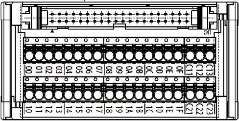
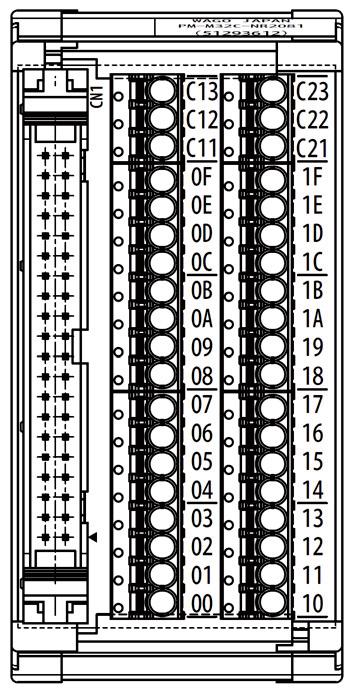
![converter module (FA1-TESV32XY) [Unit:mm]](/docs-images/80/81191145/images/10-5.jpg "5-2. 38 point spring clamp terminal")
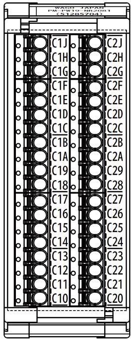
10 5.EXTERNAL DIMENSIONS point connector to spring clamp terminal converter module (FA1-TESV32XY) [Unit:mm] point spring clamp terminal (FA1-TESV38COM) [Unit:mm] 10


11 6.CONNECTING METHOD 6-1. Connection to the PLC module 11
12 6-2.Wiring to the spring clamp terminal block (1) Connecting the cable A cable with a ferrule can be inserted directly into the wire inlet. Pull the cable lightly to check that the cable does not come off. When using a stranded wire cable, insert the cable into the wire inlet while holding the release down with a flathead screwdriver. (2) Removing the cable Pull out the cable while holding the release down to the end with a flathead screwdriver. For pressing the release, use the following. Recommended tool (screwdriver) Manufacturer Item number Blade size WAGO SB (Mini type) x 0.4 mm (Insulated shaft type) 12
13 6-3. Attaching/detaching to the DIN rail (1) Mounting to the DIN rail 1) Place the DIN rail mounting groove onto the DIN rail to fit in place. 2) Press the unit toward the DIN rail until the unit clicks in place. (2) Removal from the DIN rail 1) Insert a flathead screwdriver into the hook on one side and pry the screwdriver to release the claw. Hold the unit with the claw on one side released. 2) Insert the screwdriver into the hook on another side and pry the screwdriver to detach the unit from the DIN rail. 13


14 7.INTERNAL WIRING DIAGRAM 8.EXTERNAL CONNECTION EXAMPLE 14
15 (1) When the positive common input module connection <With FA1-TESV32XY wiring> <With FA1-TESV32XY, FA1-TESV38COM wiring> 15
16 (2) When the negative common input module connection <With FA1-TESV32XY wiring> <With FA1-TESV32XY, FA1-TESV38COM wiring> 16
17 (3) When the sink output module connection <With FA1-TESV32XY wiring> <With FA1-TESV32XY, FA1-TESV38COM wiring> 17
18 (4) When the source output module connection <With FA1-TESV32XY wiring> <With FA1-TESV32XY, FA1-TESV38COM wiring> 18
 Dimensions before crimping [Unit:mm] B Dimensions A B C D MAX 1.3 8 2.8 3.")
19 9.APPLICABLE BAR SOLDERLESS TERMINALS Manufacturer WAGO Type Applicable ferrule Applicable wire size terminals Crimp tool 0.08 to 0.34 mm 2 /AWG28 to mm 2 /AWG24 and mm 2 /AWG22 and mm 2 /AWG20 and Ferrule dimensions (1) Dimensions before crimping [Unit:mm] B Dimensions A B C D MAX MIN Conduction part Insulation color (2) Dimensions after crimping Dimensions *1 A B MAX B MIN B *1: Conductor cross-sectional area is not less than 0.48 mm 2. *2: UL certification is obtained by solid/stranded wires. Ferrule shape [Unit:mm]
20 10.PRECAUTIONS (1) For wiring to the terminal block, refer to the manual of the connected programmable controller module, published by Mitsubishi Electric Corporation. 11.COVERAGE OF WARRANTY If any fault or defect (hereinafter referred to as failure ) attributable to us occurs within the terms of the product warranty, we shall replace the product free of charge via your local sales office. Terms of warranty The terms of the product warranty shall be one (1) year from the date of purchase or the delivered day to the designated place. Scope of warranty (1) The scope of warranty shall be limited to normal use based on the usage conditions, methods and environment, the specifications, or safety precautions of the product, etc., defined in the instruction manuals. (2) The following conditions are not covered with the warranty and subject to charge the product replacement, even if the valid warranty period remains. 1) Failure resulting from inappropriate storage or handling, carelessness or negligence by customer, or failure caused by customer's hardware or software design. 2) Failure caused by unapproved modifications, etc., to the product by customer. 3) Failure that could have been avoided if, when our product was assembled into customer's device, safeguards defined by legal regulations applicable to customer's device or functions or structures considered standard by the industry had been provided. 4) Failure recognized as preventable if the consumed products specified in instruction manuals, etc., were normally maintained or replaced. 5) Replacement of consumable parts (relays, etc.). 6) Failure caused by external factors beyond anyone s control such as fires or abnormal voltage, and failure caused by force majeure such as earthquakes, lightning, or wind and water damage. 7) Failure caused by reasons unpredictable by scientific technology standards at shipment from our factory. 8) Any other failure not attributable to us or which customer identifies not attributable to us. 12. EXCLUSION FROM LIABILITY FOR OPPORTUNITY LOSS AND SECONDARY LOSS Regardless of the warranty period, we shall have no liability for compensation for any damage caused by reasons not attributable to MEE, any opportunity loss or lost profit caused by a failure of our products, any damage or secondary damage caused by special circumstances whether or not foreseeable, any accident, any damage of other manufacturers products, or any customer's work such as products replacement, readjustment or launch of local machinery equipment, etc. 20
21 FOR YOUR SAFETY This product has been manufactured as a general-purpose product for general industry applications, etc. The product is not designed or manufactured to be used in equipment or systems in situations that can affect or endanger human life. When considering this product for operation in special applications such as machinery or systems used in passenger transportation, atomic power, electric power, aerospace, or medical applications, please contact your nearest Mitsubishi sales representative. Although this product was manufactured under conditions of strict quality control, the product shall be systematically provided with backup and fail-safe functions when it is used in facilities where breakdowns of the product are likely to cause a serious accident or damage Kudankita, Chiyoda-ku, Tokyo, Japan Our website URL: 50D-FG0081 Specifications subject to change without notice. Published in December
SAFETY PRECAUTIONS (Always read these precautions prior to use.)
") Terminal Block Converter Module for Programmable Controller Analog Module Model FALTB40DAG, FATB20TD, FALTB40ADGN, FALTB40TDG, FATB20TC, FALTB40ADDG, FALTB40RD3G Terminal Block Converter Module for Programmable
Terminal Block Converter Module for Programmable Controller Analog Module Model FALTB40DAG, FATB20TD, FALTB40ADGN, FALTB40TDG, FATB20TC, FALTB40ADDG, FALTB40RD3G Terminal Block Converter Module for Programmable
FX2N-2LC SPECIAL FUNCTION BLOCK
 SPECIAL FUNION BLOCK USER S GUIDE JY992D8561E Cautions on Safety (Make sure to read this paragraph before using the unit.) Thoroughly read this manual, a separate USER S MANUAL and all attached documents
EVS RP6020. Instruction Manual
 Instruction Manual TDK Lambda BEFORE USING THE PRODUCT Be sure to read this instruction manual thoroughly before using this product. Pay attention to all cautions and warnings before using this product.
POWER REGULATOR LD -40PSU
 JZ99D4121A AMPIFIRE AMPIFIRE TYPE D-4PSU ZJ-46A ISTRUCTI MAUA Manual number JZ99D4121 Sub number A Date of preparation ov. 2 Thoroughly read this instruction manual, and then use the unit correctly. Especially,
NZ2EHG-T8. User s Manual. 10/100/1000M Industrial Switching HUB MODEL NZ2EHG-T8-U MODEL CODE 13J246 IB(NA) C(1007)MEE.
 C(1007)MEE.") 10/100/1000M Industrial Switching HUB NZ2EHG-T8 User s Manual Powered by CONTEC This product was jointly developed and manufactured by Mitsubishi and CONTEC. Note that some of the warranty on this product
10/100/1000M Industrial Switching HUB NZ2EHG-T8 User s Manual Powered by CONTEC This product was jointly developed and manufactured by Mitsubishi and CONTEC. Note that some of the warranty on this product
Solid State Relays G3RV. Model Number Structure. Ordering Information. Model Number Legend. List of Models. SSR and Socket Combinations
 Solid State Relays G3RV Slimmest OMRON plug-in SSR with maximum width 6.2 mm Long electrical life and high speed switching Large plug-in terminals for reliable connection G3RV-D (DC load) models can manage
This section is specifically about safety matters
 6 4 ) 1 6 4 1 -, 1 8-4 6-4 1 6 4 7 + 6 1 ) 7 ) - -, - - + 6. 4 ) 6 J E? A Thank you for choosing this Mitsubishi transistorized Inverter option. This instruction manual gives handling information and precautions
SHOCK RELAY R INSTRUCTION MANUAL WARNING
 EHFSB006000A0 SHOCK RELAY R TSBSB Series INSTRUCTION MANUAL! WARNING Make sure you read this instruction manual thoroughly before installing, wiring, operating and inspecting this SHOCK RELAY Please make
RP Instruction Manual
 Instruction Manual TDK Lambda BEFORE USING THE PRODUCT Be sure to read this instruction manual thoroughly before using this product. Pay attention to all cautions and warnings before using this product.
Filterpack FR-BFP2-(H)0.4K to (H)15K
0.4K to (H)15K") INVERTER INSTRUCTION MANUAL FR-BFP2-(H)0.4K to (H)15K 1. Product Checking... 1 2. Applicable Inverter... 1 3. Installation... 2 3.1 Inverter Installation (installation of the )...2 4. Wiring... 4 5. Main
INVERTER INSTRUCTION MANUAL FR-BFP2-(H)0.4K to (H)15K 1. Product Checking... 1 2. Applicable Inverter... 1 3. Installation... 2 3.1 Inverter Installation (installation of the )...2 4. Wiring... 4 5. Main
HARDWARE MANUAL. 1. Introduction. 2. Outline of Product. 3. Name of Each Part [MAIN UNIT INSTRUCTION MANUAL] JY992D88901B
![HARDWARE MANUAL. 1. Introduction. 2. Outline of Product. 3. Name of Each Part [MAIN UNIT INSTRUCTION MANUAL] JY992D88901B](/thumbs/81/83992362.jpg "HARDWARE MANUAL. 1. Introduction. 2. Outline of Product. 3. Name of Each Part [MAIN UNIT INSTRUCTION MANUAL] JY992D88901B") CONNECTOR CONVERSION BOX F9GT-HCNB HARDWARE MANUAL [MAIN UNIT INSTRUCTION MANUAL] This manual only describes the specifications for Connector Conversion Box F9GT-HCNB. For complete operation, wiring, mounting
CONNECTOR CONVERSION BOX F9GT-HCNB HARDWARE MANUAL [MAIN UNIT INSTRUCTION MANUAL] This manual only describes the specifications for Connector Conversion Box F9GT-HCNB. For complete operation, wiring, mounting
NZ2EHG-T8N. User s Manual. 10/100/1000M Industrial Switching HUB MODEL NZ2EHG-T8N-U MODEL CODE 13J026 IB(NA) A(1601)MEE.
 A(1601)MEE.") 10/100/1000M Industrial Switching HUB NZ2EHG-T8N User s Manual Powered by CONTEC This product was jointly developed and manufactured by Mitsubishi and CONTEC. Note that some of the warranty on this product
10/100/1000M Industrial Switching HUB NZ2EHG-T8N User s Manual Powered by CONTEC This product was jointly developed and manufactured by Mitsubishi and CONTEC. Note that some of the warranty on this product
Differential Pressure Transmitter
 Specifications/Instructions Differential Pressure Transmitter General Model PY9000D is a differential pressure transmitter that uses a ceramic cantilever sensor. Deflection of the ceramic cantilever caused
Accessories for Wind Power Inverter WINDY BOY PROTECTION BOX 400 / 500 / 600
 Accessories for Wind Power Inverter WINDY BOY PROTECTION BOX 400 / 500 / 600 Installation Guide WBP-Box-IEN103320 IMEN-WBP-BOX Version 2.0 EN SMA Solar Technology AG Table of Contents Table of Contents
HS6B Series Subminiature Interlock Switch
 HS6B Series Subminiature Interlock Switch HS6B features: Only 78 x 30 x 15mm Allows highest level of safety by having 3 contacts: dual load contacts + monitoring contact (ISO13849-1, EN954-1) Two actuator
No.EX -OME0016-A PRODUCT NAME. SI unit. MODEL / Series / Product Number EX140-SDN1
 No.EX -OME0016-A PRODUCT NAME SI unit MODEL / Series / Product Number EX140-SDN1 Table of Contents 1. Safety instructions 2 2. Specifications 7 2-1. General specifications 7 2-2. Electrical ant network
(with Class-1 AC resistive load) 3. G3PB-215B-2N-VD kW max. (25 A) G3PB-225B-3N-VD 2. G3PB-225B-2N-VD kw max. (35 A) G3PB-235B-3N-VD 2
 3. G3PB-215B-2N-VD kW max. (25 A) G3PB-225B-3N-VD 2. G3PB-225B-2N-VD kw max. (35 A) G3PB-235B-3N-VD 2") Solid-state Contactor (New Heat Sink Construction) G3PB Space and working time saved with new heat sink construction. Series now includes 480-VAC models to allow use in a greater range of applications.
Solid-state Contactor (New Heat Sink Construction) G3PB Space and working time saved with new heat sink construction. Series now includes 480-VAC models to allow use in a greater range of applications.
HS6B Series Sub-Miniature Interlock Switch. Direct Opening
 HS6 Series HS6 Series Sub-Miniature Interlock Switch HS6 Key features include: Only 30mm x 15mm x 78mm Allows highest level of safety by having 3 contacts: dual load contacts + monitoring contact (ISO13849-1,
NIDEC COPAL ELECTRONICS CORP.
 1 / 8 Specifications Model No. TF037F-2000-F Issuing Date Aug.1, 2017 1.Scope This document applies to Blower TF037F-2000-F (hereinafter referred to as "PRODUCT"), a product of NIDEC COPAL ELECTRONICS
SAFETY INFORMATION & INSTALLATION GUIDE RMX Programmable Power Supplies. About the RMX Safety Information & Installation Guide
 SAFETY INFORMATION & INSTALLATION GUIDE RMX Programmable Power Supplies RMX-4120/4121/4122/4123/4124/4125/4126/4127 About the RMX Safety Information & Installation Guide This guide is intended for users
User s Manual Power Supply. IM E 2nd Edition. Yokogawa Electric Corporation
 User s Manual 701934 Power Supply Yokogawa Electric Corporation 2nd Edition Foreword Revisions Thank you for purchasing the 701934 Power Supply. This user's manual contains useful information about the
VM-5 SERIES MONITOR MODEL VM-5Z3 POWER SUPPLY UNIT INSTRUCTION MANUAL
 MANUAL NO. 20009E1.3 Published in Nov.2000 Revised in Mar. 2010 VM-5 SERIES MONITOR MODEL VM-5Z3 POWER SUPPLY UNIT INSTRUCTION MANUAL SAFETY CONVENTIONS VM-5Z3 For safe operation... Thank you for using
Operation Key D4BS - K Head Mounting Direction F: Four mounting directions possible (front-side mounting at shipping)
") Safety-door Switch D4BS The Special Activates a Direct Opening Mechanism to Open the Contacts and Shut Off Control Circuits when Protective Doors Are Opened on Machine Tools or Other Equipment CSM_D4BS_DS_E_6_1
Safety-door Switch D4BS The Special Activates a Direct Opening Mechanism to Open the Contacts and Shut Off Control Circuits when Protective Doors Are Opened on Machine Tools or Other Equipment CSM_D4BS_DS_E_6_1
Model Number Structure
 Conductive Level Controller CSM DS_E_1_1 Ideal for level control for industrial facilities and equipment. Outputs can be set to self-hold at or using self-holding circuits. Sensitivity adjustment of operating
Safety Products. Safety Products. HS5E Series. HS5E Series Miniature Solenoid Locking Switch
 HS5E Series HS5E Series Miniature Solenoid Locking Switch HS5E Key features include: World s smallest 4 contact solenoid interlock switch. (35 40 46 mm.) Four contacts. Gold-plated contacts. Spring lock
Digital display Pressure range ON/OFF output Linear output Model
 Slim Digital Pressure Sensor E8CC with Built-in Microcomputer and Digital Display Withstands a pressure of 49 kpa and highly reliable. Incorporates a two-turn pressure adjuster ensuring easy pressure setting.
panasonic.net/id/pidsx/global Solve issues related to machine safety and other safety measures with a safety door switch with key!
 655 Door with Key SERIES Related Information General terms and conditions... F-7 General precautions... P.50 PHOTO PHOTO Conforming to Machine & EMC Directives Recognition Certified MEASURE ITY panasonic.net/id/pidsx/global
Safety-door Switch. Ordering Information
 Safety-door Switch Safety-door Switch s Special Operation Key Positively Pulls Apart the Contacts from Each Other and Contributes to the Safety of the Production Site Special Operation Key prevents mis-operation.
Cat. No. I526-E1-1 USER S MANUAL 3G3IV-PLKEB2 /4. Braking Resistor Units 3G3IV-PCDBR2 B/4 B. Braking Units
 Cat. No. I526-E1-1 USER S MANUAL 3G3IV-PLKEB2 /4 Braking Resistor Units 3G3IV-PCDBR2 B/4 B Braking Units Thank you for choosing an OMRON Braking Resistor Unit and Braking Unit. Proper use and handling
D4BS CSM_D4BS_DS_E_8_4
 Safety-door Switch CSM DS_E_8_4 The Special Activates a Direct Opening Mechanism to Open the Contacts and Shut Off Control Circuits when Protective Doors Are Opened on Machine Tools or Other Equipment
HS1C Interlock Switches with Solenoid
 HSC es with The guard door remains locked until the machine stops completely. With the actuator mounted on the guard door and the interlock switch on the machine, the door is mechanically locked when closed.
HS1C Series Full Size Interlock Switch with Locking Solenoid. GS-ET-15 BG standard in Germany. HS1C Series Functionality
 Full Size Interlock Switch with Locking Solenoid HSC Key features include: Rugged Aluminum Die-cast Housing With the actuator mounted on a movable door, and the switch on a machine, the door can be mechanically
Model Number Structure
 Solid State Relays CSM OEE_DS_E_1_2 Extremely Thin Relays Integrated with Heat Sinks Downsizing achieved through optimum design of heat sink. Mounting possible via screws or via DIN track. Close mounting
TOWA SEIDEN INDUSTRIAL CO., LTD.
 INSTRUCTION MANUAL SOUNDING LEVEL METER MODEL: TLX-120AP/200AP Meanings of indications for safety used in this Instruction Manual are as follows. WARNING: Indicates that improper handling assumes the risk
G3PE-Single-phase. Solid State Relays for Heaters
 Solid State Relays for Heaters Single-phase CSM_Single-phase_DS_E Compact, Slim-profile SSRs with Heat Sinks. s with No Zero Cross for a Wide Range of Applications. RoHS compliant. s also available with
HS1L Interlock Switches with Solenoid
 HS1L Interlock Switches with Solenoid 3000N locking strength (largest in class)! * Suitable for large and heavy doors. Same actuator as HS1E (actuator retention force 3000N) Six contacts in a compact housing
Contents. Introduction Inspection Notes on Safety Precautions. Chapter 1 Overview Product Overview Names of Parts 2
 INSTRUCTION MANUAL Contents Introduction Inspection Notes on Safety Precautions i i ii vii Chapter 1 Overview 1 1.1 Product Overview 1 1.2 Names of Parts 2 Chapter 2 Specifications 5 2.1 Product Specifications
Ordering Information. Specifications. Motor Time Switch H2F-WM. Accessories (Order Separately) Time Specifications. Ratings
 Time Specifications. Ratings") Motor Time Switch H2F-WM CSM_H2F-WM_DS_E_2_1 Weekly ON/OFF Control in 1-h Increments The H2F-WM is a Compact Weekly Time Switch in a DIN -mm Body Equipped with Power Interruption Backup Providing Protection
Motor Time Switch H2F-WM CSM_H2F-WM_DS_E_2_1 Weekly ON/OFF Control in 1-h Increments The H2F-WM is a Compact Weekly Time Switch in a DIN -mm Body Equipped with Power Interruption Backup Providing Protection
HS1E Series Full Size Solenoid Locking Switches
 HS1E Series Full Size Solenoid Locking Switches AS-Interface Safety at Work Barriers Enabling Switches Door Interlock Switches X Series E-Stops Overview HS1E features: Basic unit and solenoid unit in one
SG-B1 SERIES / SG-A1 SERIES
 643 Door with Solenoid Interlock / Door Ultra-slim SG-B1 SERIES / SG-A1 SERIES Related Information General terms and conditions... F-7 General precautions... P.1501 PHOTO PHOTO Conforming to Machine &
HS1B Series Full Size Interlock Switch. GS-ET-15 BG standard in Germany. Part Number Key
 HSB Series Full Size Interlock Switch HSB features: Rugged aluminum die-cast housing Direct Opening Action: If the door is forced open, the contacts are disconnected even if they are welded or stuck Available
UZK12.071, UZO GENERAL DESCRIPTION 2. DATA 3. ORDER NUMBERS 4. MARKINGS BATTERY MODULE BATTERY MODULE 12V, 7AH 1/9.
 BATTERY MODULE Two Mounting Options: DIN-Rail or Panel/ Wall Mounting IP00 Open Type Protection Level Easy Access to the Terminals and the Fuse Heavy Duty Fuse Holder and Spare Fuse Included UZK12.071
NIDEC COPAL ELECTRONICS CORP.
 NIDEC COPA EECTRONICS CORP. 1 / 5 Specifications Model No. TF037C-2100-F Issuing Date Aug.1, 2017 1. Scope This specification applies to Blower TF037C-2100-F (hereinafter referred to as "the PRODUCT"),
UZK12.071, UZO DATA 1. GENERAL DESCRIPTION 4. MARKINGS 3. ORDER NUMBERS PASSIVE BATTERY MODULE BATTERY MODULE 12V, 7AH 1/9.
 PASSIVE BATTERY MODULE Two Mounting Options: DIN-Rail or panel/wall mounting IP00 Open Type Protection Level Easy Access to the Terminals and the Fuse Heavy Duty Fuse Holder and Spare Fuse Included 1.
HS1E Series Full Size Interlock Switch with Locking Solenoid
 HS1E Series HS1E Series Full Size Interlock Switch with Locking Solenoid HS1E Key features include: Basic unit and solenoid unit in one housing Plastic Housing: Light weight Ease of Wiring: All the terminal
WARNING Warnings are indicated when mishandling this product might result in death or serious injury to the user.
 CP-UM-5706E Product by Germany s Elster GmbH High-Performance Gas Solenoid Valve for Industrial Applications GV-A User's Manual WARNING Before wiring, installing, or removing the unit, be sure to turn
HEAVY DUTY POWER RELAYS FEATURES
 VDE VC HEAVY DUTY POWER RELAYS VC RELAYS Faston terminal Screw terminal mm 9 FEATURES VC power relays are designed for controlling heavy duty loads safely: Contact gap of 3 mm or more -point contacts for
Hinged Safety Door Switch
 Hinged Safety Door Switch Polymer housing, IP65, and slow-action contacts with positive opening. Two actuator types are available: Shaft Arm lever Arm lever type can be adjusted to allow a right (180 ),
Pressure Transmitter
 Specifications/Instructions Pressure Transmitter General Model PY7100A pressure transmitter is a small pressure transmitter using a semiconductor strain gauge. It detects the pressure of chilled/hot water,
Spec.No. CBF2525-VBVB-01E-1. Orion Model CBF2525-VBVB-01. Date Aug APPD CKD DWN. Kuroiwa Yamada Takei Takahashi ORION MACHINERY CO., LTD.
 Spec.No. CBF2525-VBVB-01E-1 Orion Trade Name DRY PUMP Orion Model CBF2525-VBVB-01 Date Aug.30.2011 APPD CKD DWN Y. F. N. Y. Kuroiwa Yamada Takei Takahashi ORION MACHINERY CO., LTD. Spec.No. CBF2525-VBVB-01E-1
HS1B R - R. Door Interlock Switches. HS1B Series. HS1B Series Full Size Interlock Switch. Part Number. HS1B features: Part Number Key.
 HSB Series HSB Series Full Size Interlock Switch HSB features: Body Rugged aluminum die-cast housing Direct Opening Action: If the door is forced open, the contacts are disconnected even if they are welded
VF-S11 RS485 built-in board option RS4003Z Instruction Manual
 VF-S11 RS485 built-in board option RS4003Z Instruction Manual NOTICE 1. Make sure that this instruction manual is delivered to the end user of RS485 built-in option board. 2. Read this manual before installing
GETTING STARTED GUIDE NI AO, ±10 V, 16 Bit, 25 ks/s/ch Simultaneous
 GETTING STARTED GUIDE NI 9264 16 AO, ±10 V, 16 Bit, 25 ks/s/ch Simultaneous This document explains how to connect to the NI 9264. In this document, the NI 9264 with spring terminal and the NI 9264 with
0.5 s to 30 h (30 s, 3 min, 30 min, 3 h, 30 h)
") Mechatronic Analog Timer H3AM Please read and understand this catalog before purchasing the products. Please consult your OMRON representative if you have any questions or comments. Refer to Warranty and
Mechatronic Analog Timer H3AM Please read and understand this catalog before purchasing the products. Please consult your OMRON representative if you have any questions or comments. Refer to Warranty and
HS2B N B - R. Door Interlock Switches. HS2B Series. Full Size Interlock Switch. Part Number. HS2B features: Part Number Key.
 HSB Series HSB Series Full Size Interlock Switch HSB features: Body Direct Opening Action: If the door is forced open, the contacts are disconnected even if they are welded or stuck Available with or without
Applicable output load (See note 2.) Photocoupler Yes Yes 40 A at 110 to 220 VAC 5 to 24 VDC G3NB-240B 5 to 24 VDC G3NB-240B-UTU 5 to 24 VDC
 Photocoupler Yes Yes 40 A at 110 to 220 VAC 5 to 24 VDC G3NB-240B 5 to 24 VDC G3NB-240B-UTU 5 to 24 VDC") Solid State Relays G3NB with 40-A output at a reasonable price. Switches 9 A without a heat sink. Zero cross function enables less noise operation. Built-in varistor effectively absorbs external surges.
Solid State Relays G3NB with 40-A output at a reasonable price. Switches 9 A without a heat sink. Zero cross function enables less noise operation. Built-in varistor effectively absorbs external surges.
20 amps 220 amps, 60 Hz VDC VAC G3PA-420B-VD-2 DC amps 440 amps, 60 Hz G3PA-450B-VD-2 DC12-24
 Solid State Relays (SSRs) G3PA/G3PB Long Service Life for Circuits that Cycle Frequently D D D D D Built-in heat sink increases life and reliability Voltage turn-on at zero crossing reduces initial inrush
Sola/Hevi-Duty S3K Series Mini-Tower UPS
 Sola/Hevi-Duty S3K Series Mini-Tower UPS GUIDE SPECIFICATIONS 700VA to 1600VA 120V models Single - Phase Uninterruptible Power Supply Systems 1.1 SUMMARY 1.0 GENERAL This specification defines the electrical
Life PERFORMANCE Catalog listing Standards Structure Electrical performance Mechanical performance Ambient operating conditions Recommende tightening
 SPATTER-GUARDED SWITCHES Model LS Effective countermeasures against the adhesion of spatter. UL/CSA/GB(CCC marking)-approved. (excluding some models) ORDER GUIDE Actuator Name Roller lever type Shape Max.
User s Manual Power Supply IM E. 5th Edition
 User s Manual 700938 Power Supply 5th Edition Thank you for purchasing the 700938 Power Supply. This user s manual contains useful information about the instrument s functions and operating procedures
Door Interlock Switches
 HSE Series HSE Series Full Size Locking Switches Overview X Series E-Stops HSE features: Basic unit and solenoid unit in one housing Plastic Housing: Light weight Ease of Wiring: All the terminal screws
DRB-1 Series Instruction Manual
 Instruction Manual BEFORE USING THE POWER SUPPLY UNIT Pay attention to all warnings and cautions before using the unit. Incorrect usage could lead to an electrical shock, damage to the unit or a fire hazard.
ABL Series. Relay Terminal Block (Screwless Type) Features
 Features") ABL Series Relay Terminal Block (Screwless Type) Features Input (NPN, PNP common) and Output (Independent, Common) Selection with Jumper Bars Allows switching between NPN common and PNP common inputs by
ABL Series Relay Terminal Block (Screwless Type) Features Input (NPN, PNP common) and Output (Independent, Common) Selection with Jumper Bars Allows switching between NPN common and PNP common inputs by
D4GS-N CSM_D4GS-N_DS_E_7_2
 Slim Safety Door Switch D4GS-N CSM_D4GS-N_DS_E_7_2 Slim Safety Door Switches with IP67 Rating Slim design with a width of only 17 mm (three-contact models). Reversible design allowing either front or rear
UZK12.261, UZO GENERAL DESCRIPTION 2. SHORT-FORM DATA 3. ORDER NUMBERS 4. MARKINGS BATTERY MODULE BATTERY MODULE 12V, 26AH 1/10.
 BATTERY MODULE Long Life Battery: 10 to 12 Years According to EUROBAT Small Mounting Footprint Easy Access to the Terminals and the Fuse Heavy Duty Fuse Holder and Spare Fuse Included 3 Year Warranty,
XW2R-COM. Common Terminals X W 2R - P D - COM. Space-saving and less wiring work of power supply wiring are achieved. Application Example
 Common Terminals XW2R-COM CSM_XW2R-P_M_B-COM_DS_E Space-saving and less wiring work of power supply wiring are achieved. Common wiring is already wired on the PCB, transition wiring is unnecessary. Wiring
High-power Solid State Relays G3PH
 New Product News High-power Solid State Relays G3PH High-power, Load-control s with High Current of 75 or 150 A and High Voltage of 240 or 480 VAC RoHS compliant. Models also available with no zero cross.
GETTING STARTED GUIDE NI AI, ±10 V, 12 Bit, 500 ks/s Aggregate
 GETTING STARTED GUIDE NI 9201 8 AI, ±10 V, 12 Bit, 500 ks/s Aggregate This document explains how to connect to the NI 9201. In this document, the NI 9201 with screw terminal, NI 9201 with spring terminal,
HS1C-P Interlock Plug Unit with Door Lock
 HSC-P Unit with Lock Interlock plugs with door lock mechanism for high level safety management. Installing the actuator on the guard door and the interlock switch on the machine, the guard door can be
Infilex ZM Zone Manager Model WY5122
 Specifications/Instructions Infilex ZM Zone Manager Model WY5122 General Infilex ZM (Infilex: named for Infinity and Flexible ) Model WY5122, integrated into savic-net FX BMS (building management system),
HS1L Interlock Switches with Solenoid
 3000N locking strength (largest in class)! * Suitable for large and heavy doors. Same actuators as HS1E (locking strength 3000N) can be used. *As of October 2009, according to IDEC research of plastic
Operation Manual. Document No.: KE KITZ EKSR Series Spring Return Type Electric Actuators. For KITZ Ball Valves
 Document No.: KE-4041-00 Operation Manual KITZ EKSR Series Spring Return Type Electric Actuators For KITZ Ball Valves Thank you for choosing KITZ products. For safe and trouble-free function and performance
FR-BU2-1.5K to 55K FR-BU2-H7.5K to H280K
 INVERTER INSTRUCTION MANUAL Brake Unit FR-BU2-1.5K to 55K FR-BU2-H7.5K to H280K Thank you for choosing this Mitsubishi Inverter option unit. This Instruction Manual gives handling information and precautions
Notice for TAIYO YUDEN Products
 Notice for TAIYO YUDEN Products [ For the TAIYO YUDEN Products excluding Ceramic Capacitors and Inductors ] Please read this notice before using the TAIYO YUDEN products. REMINDERS Product information
E2E2. Proximity Sensor with a Long Screw Length. Long-barrel Inductive Proximity Sensor. Ordering Information. Sensors DC 2-Wire Models
 Long-barrel Inductive Proximity Sensor EE CSM_EE_DS_E Proximity Sensor with a Long Screw Length Increased tightening strength. Cable protectors provided as a standard feature. Increased indicator visibility.
HS5E Miniature Interlock Switches with Solenoid
 Small interlock switch with four poles and solenoid. Ideal for applications in small spaces. Compact body. 3 40 46 mm. Four-pole internal switches. Gold-plated contacts. Spring lock and solenoid lock types
D4BS. Safety-door Switch. Model Number Structure. Switch D4BS - S Operation Key D4BS - K. Ordering Information
 Safety-door Switch Safety-door Switch s Special Operation Key Directly Pulls Apart the Contacts from Each Other and Contributes to the Safety of the Production Site Conforms to EN (TÜV) standards corresponding
Powerware Vdc Extended Battery Cabinet User s Guide.
 Powerware 9125 48 Vdc Extended Battery Cabinet User s Guide www.powerware.com FCC Part 15 Class A EMC Statements NOTE This equipment has been tested and found to comply with the limits for a Class A digital
System Monitoring SCHOOLMETERBOX AU
 System Monitoring SCHOOLMETERBOX AU Installation Guide SMETER-IEN084710 98-00013210 Version 1.0 EN SMA Solar Technology AG Table of Contents Table of Contents 1 Notes on this Manual..............................
DRL-1 Series Instruction Manual
 DRL-1 Series Instruction Manual BEFORE USING THE POWER SUPPLY UNIT Pay attention to all warnings and cautions before using the unit. Incorrect usage could lead to an electrical shock, damage to the unit
B-RAD Select USER MANUAL TABLE OF CONTENTS
 TABLE OF CONTENTS TABLE OF CONTENTS... 1 MANUAL REVISION HISTORY... 2 IMPORTANT SAFETY NOTICE... 3 1.0 General Information... 5 1.1 System Components... 5 1.2 Specifications... 5 1.2.1 Torque Ranges...
MITSUBISHI LARGE CAPACITY INVERTER MELTRAC-REC(MT-REC) -INSTRUCTION MANUAL- 12 Pulse Bridge Converter
 -INSTRUCTION MANUAL- 12 Pulse Bridge Converter") A MITSUBISHI LARGE CAPACITY INVERTER 12 Pulse Bridge Converter MELTRAC-REC(MT-REC) -INSTRUCTION MANUAL- NOTICE : READ ENTIRE MANUAL PRIOP TO CONNECTING AND OPERATING EQUIPMENT IB-T7237B Thank you for choosing
A MITSUBISHI LARGE CAPACITY INVERTER 12 Pulse Bridge Converter MELTRAC-REC(MT-REC) -INSTRUCTION MANUAL- NOTICE : READ ENTIRE MANUAL PRIOP TO CONNECTING AND OPERATING EQUIPMENT IB-T7237B Thank you for choosing
2-Color Display Digital Pressure Switch. NPN/PNP open collector 2 outputs added. Cut-to-zero display function added. Rated Pressure Metal Body Type
 Series ISE70/75/75H New NPN/PNP open collector 2 outputs added. Cut-to-zero display function added. For General Fluids For Air 2-Color Display (Green/Red) Selectable from four patterns ON Red Green Red
D4DS. Safety-Door Switch. Compact Safety Switch Saves Space and is Ideal for a Variety of Doors. H Conforms to EN (TÜV) standards.
 standards.") Safety-Door Switch Compact Safety Switch Saves Space and is Ideal for a Variety of Doors H Conforms to EN (TÜV) standards. (positive opening mechanism isindicatedonthe switch) H Wide standard operating
Safety-Door Switch Compact Safety Switch Saves Space and is Ideal for a Variety of Doors H Conforms to EN (TÜV) standards. (positive opening mechanism isindicatedonthe switch) H Wide standard operating
2NC (slow-action) Direct. Model. opening
 Direct. Model. opening") Small Safety Limit Switch CSM DS_E_3_1 Smallest Class of Safety Limit Switches in the World Note: Contact your sales representative for details on models with safety standard certification. The world's
Small Safety Limit Switch CSM DS_E_3_1 Smallest Class of Safety Limit Switches in the World Note: Contact your sales representative for details on models with safety standard certification. The world's
Sense7-series Non-contact coded safety switch
 Original instructions Sense7-series Non-contact coded safety switch ABB AB / Jokab Safety Varlabergsvägen 11, SE-434 39 Kungsbacka, Sweden www.abb.com/jokabsafety Read and understand this document Please
Switching DC Power Supply
 99 Washington Street Melrose, MA 02176 Phone 781-665-1400 Toll Free 1-800-517-8431 Visit us at www.testequipmentdepot.com Model 1693, 1694 Switching DC Power Supply INSTRUCTION MANUAL 1 Safety Summary
Door Interlock Switches
 HS5B Series HS5B Series Miniature Interlock Switch HS5B features: mm x mm x 9mm Compact Housing Available with Contact Confi gurations (NO + NC or NC) Flexible Installation: By turning the head of the
Battery Unit BHM60PC/BHM100PC Instruction Manual
 Battery Unit BHM60PC/BHM100PC Instruction Manual For the use of UPS BH60PCW/BH100PCW This manual contains important information regarding the safe use of the BHM60PC/BHM100PC for the Backup Power Supply
DIGITAL BATTERY TORQUE WRENCH (BC-RAD SELECT) USER GUIDE
 USER GUIDE") DIGITAL BATTERY TORQUE WRENCH (BC-RAD SELECT) USER GUIDE W.CHRISTIE (INDUSTRIAL) LTD CHRISTIE HOUSE, MEADOWBANK ROAD, ROTHERHAM, SOUTH YORKSHIRE, S61 2NF, UK T: +44(0)1709 550088 F: +44(0)1709 550030 E:
DIGITAL BATTERY TORQUE WRENCH (BC-RAD SELECT) USER GUIDE W.CHRISTIE (INDUSTRIAL) LTD CHRISTIE HOUSE, MEADOWBANK ROAD, ROTHERHAM, SOUTH YORKSHIRE, S61 2NF, UK T: +44(0)1709 550088 F: +44(0)1709 550030 E:
UZK24.121, UZO GENERAL DESCRIPTION 2. DATA 4. MARKINGS 3. ORDER NUMBERS
 PASSIVE BATTERY MODULE 24V, 12Ah Battery Capacity (2x 12V Batteries in Series) IP00 Open Type Protection Level Small Mounting Footprint ATO Fuse for Power Wires Included 2m Power Leads Included PT1000
THT-500-A/R INSTRUCTION MANUAL TEMPERATURE AND HUMIDITY TRANSMITTER
 INSTRUCTION MANUAL TEMPERATURE AND HUMIDITY TRANSMITTER THT-500-A/R No.THT51E1 2017.12 Thank you for purchasing our THT-500-A/R, Temperature and Humidity Transmitter (mounted within control panel). This
No.LV31JE To prevent accidents arising from the misuse of this instrument, please ensure the operator receives this manual.
 INSTRUCTION MANUAL LEVEL SWITCH LV-300 No.LV31JE2 2008.05 To prevent accidents arising from the misuse of this instrument, please ensure the operator receives this manual. Safety Precautions (Be sure to
Operating Instructions
 Gearmotors \ Industrial Gear Units \ Drive Electronics \ Drive Automation \ Services BMG..T Double Disc Brakes for Stage Applications A6.C86 Edition 06/2004 11295228 / EN Operating Instructions SEW-EURODRIVE
E2Q6. Rectangular Proximity Sensor. Freely Change the Sensing Direction. Ordering Information. Sensors [Refer to Dimensions on page 6] DC Models
![E2Q6. Rectangular Proximity Sensor. Freely Change the Sensing Direction. Ordering Information. Sensors [Refer to Dimensions on page 6] DC Models](/thumbs/77/76421587.jpg "E2Q6. Rectangular Proximity Sensor. Freely Change the Sensing Direction. Ordering Information. Sensors [Refer to Dimensions on page 6] DC Models") Rectangular Freely Change the Sensing Direction Change between any of five sensing directions: front or 9 up, down, left, or right. Four indicators show the operating status of the from many directions.
Rectangular Freely Change the Sensing Direction Change between any of five sensing directions: front or 9 up, down, left, or right. Four indicators show the operating status of the from many directions.
ITVX Series. Stepless control of air pressure proportional to an electrical signal. Supply pressure: 5.0 MPa
 5.0 MPa Maximum Supply Pressure High Pressure Electro-Pneumatic Regulator X Series This product is only for blowing gas. This product does not have sufficient pressure control for other applications (driving,
 CHAIN COUPLINGS FLEXIBLE COUPLINGS CR6022FB-H35J G40F CN 3 10 WARNING CAUTION Safety Instructions Death or serious injury may result from misusing the product without following the directions
NIDEC COPAL ELECTRONICS CORP. 1 / 7. Model No. Issuing Date
 NIDEC COPAL ELECTRONICS CORP. / 7 Specifications Model No. Issuing Date TF037C-200-P Aug., 207. Scope This specification applies to Blower Kit:TF037C-200-P (hereinafter referred to as "the PRODUCT"), a
UZK24.071, UZO GENERAL DESCRIPTION 2. SHORT-FORM DATA 3. ORDER NUMBERS 4. MARKINGS
 BATTERY MODULE 24V, 7Ah Battery Capacity (2x 12V Batteries in Series) Small Mounting Footprint 2m Power Leads Included PT1000 Sensor for Battery Module Temperature Included Includes a Center-tap Terminal
Solid State Relays G3NA. Model Number Structure. Model Number Legend
 Solid State Relays G3NA The reliable choice for Hockey-puck-style Solid State Relays. Available in a Wide Range of Currents. All models feature the same compact dimensions to provide a uniform mounting