Table of Contents. Page # Table of Contents. 2 Precautions 3 SPECIFICATIONS. 4 Overview. 6 Installation. 9 Measure Wheel Size. 14 Data Setting Mode
|
|
|
- Amanda Black
- 6 years ago
- Views:
Transcription

1
2
3 Table of Contents Page # Table of Contents 1 A Note To You 2 Precautions 3 SPECIFICATIONS 4 Overview 6 Installation 9 Measure Wheel Size 14 Data Setting Mode 16 Normal Mode Screens 28 VAPOR FEATURES 30 Troubleshooting 40 Glossary of Terms 42 1
4 A Note to You Thanks for Buying a Trail Tech Powersport Computer: Trail Tech powersport computers bring functionality and life to your motor vehicle with high quality and innovation. To ensure you enjoy years of trouble-free operation, this user s manual contains valuable information about how to operate and maintain your computer properly. Please read this manual carefully. Please Record Important Information: Whenever you call to request service for Vapor, you need to know the date of purchase, dealer s name, address, and telephone number. PURCHASE DATE DEALER NAME DEALER ADDRESS DEALER PHONE Keep this book and sales slip together for future reference. 2
5 Precautions WARNING: When using Vapor, follow basic precautions, including the following: Check relative positions and gap between sensor and magnet periodically. Read all instructions before using Vapor. Do not bend, twist, kink or otherwise abuse the black sensor cable. A damaged cable may produce incorrect readings. Use Vapor only for its intended function. To reduce the risk of injury, do not disassemble Vapor or its accessories. Vapor can be used in the rain but should not be used underwater. Do not leave the main unit in direct sunlight when not riding. Do not abuse wires on back of Vapor. The wires carry high voltage power from the vehicles ignition system. Damaged wires may also produce incorrect readings. Avoid contact with gasoline, degreasers or other chemical cleaners as they may damage the computer. REMEMBER TO PAY ATTENTION TO THE TRAIL WHILE RIDING. 3
6 Specifications FUNCTION DISPLAY RANGE CURRENT SPEED SPD KM/H or M/H REVS PER MINUTE RPM RPM RPM BAR GRAPH Graphical RPM MAXIMUM SPEED MS KM/H or M/H DISTANCE DST KM or M STOP WATCH TT 0 ODOMETER ODO RIDE TIME RT hour 59 min ACCUM. RIDE TIME ART hour 59 min 12H or 24H CLOCK 00:00:00 12:59:59 or 23:59:59 LOW BATTERY LO hour 59 min About 1 Year Life TIRE SIZE 0 ENGINE TEMP (-30C - 270C) ( F) Ambient Temp (-40C - 125C/257F) SPEED/DISTANCE SENSOR TEMPERATURE SENSORS RPM SENSOR PRODUCT DIMENSIONS SCREEN DIMENSIONS mm Non-contact Magnetic Speed Sensor Ambient and Engine Temp. Sensors Electrical Pulse Sensor x59.46x23.7mm WxHxD (4.21x2.34x0.93 WxHxD) x 28.6mm WXH (3.1 x 1.13 WxH)
7 Specifications UNITS INCREMENTS ACCURACY KM/H or M/H 0.1 KM/H or M/H +/- 0.1% KM/H or M/H 10 RPM +/- 0.1% KM/H or M/H Variable +/- 0.1% KM/H or M/H 0.1 KM/H or M/H +/- 0.1% KM/H or M/H 0.1 KM/H or M/H +/- 0.1% Hours:Minutes 1 Second +/- 0.1% KM or M 1 +/- 0.1% Hours:Minutes 1 Minute +/- 0.1% Hours:Minutes 1 Minute +/- 0.1% H:M:S +/- 0.1% 2.5 Volts +/- 0.1% PRODUCT WEIGHT WHEEL CIRCUMFERENCE OPERATION TEMPERATURE STORAGE TEMPERATURE BATTERY BATTERY LIFE EXTERNAL POWER INPUT 3.9 oz. (110 grams) (0.24 lbs.) 0 to 3999 mm 0 C to 60 C (32 F to 140 F) -20 C to 80 C (-4 F to 176 F) 3V CR2032 About 1 Year VAC/VDC (No polarity requirements.) 5
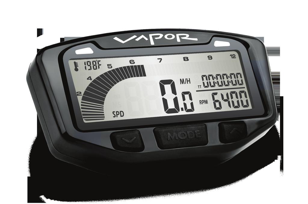
8 Overview Vapor Computer: Vapor holds a large amount of information in a small space. There are three buttons for easy navigation, two LED s for alerts and warnings, and a brightly lit LCD panel for easy viewing. YELLOW LED RED LED LCD SCREEN LEFT BUTTON MODE BUTTON Quickstart Commands: RIGHT BUTTON <MODE> = Switch between screens in Normal Mode. <LEFT> + <MODE> = Reset Trip Data: Maximum Speed, Distance, Ride Time, Stop Watch, Max Engine Temperature, and Max RPM. <RIGHT> = Toggle between features in Normal Mode screens. <MODE> FOR 3 SEC = Edit Trip Distance (DST) value. - <LEFT> or <RIGHT> = Increment or scroll distance value. <LEFT> <CENTER> + <RIGHT> = Enter Data Setting Mode. - <MODE> = Move to next data setting screen. - <LEFT> = Increment or scroll through current data setting. - <RIGHT> = Move to next digit in data setting mode. 6
9 Parts & Features Backlight: Vapor is equipped with a backlight for easy viewing during night-time operation. Using External 12V Power: Vapor will light up with all five LED s. Vapor will remain lit as long as it senses wheel movement. After 5 minutes of inactivity Vapor shuts off the backlight. Press any button, roll the wheels, or start the motor power and Vapor will light up again. Shift and Temperature LED s will be enabled. Using Internal Battery Only: Vapor will only stay lit for 3 seconds. Vapor s backlight will light up with 10% power to conserve battery power. If the LO symbol is present, the backlight will not turn on. The LO symbol appears when battery voltage drops below 2.45V. If ambient temperature is cold (below -5 C) the backlight will not ENGINE TEMP TO ACTIVATE BACKLIGHT MANUALLY, PRESS If connected to 12V power, press any key to activate the backlight. 7
10 Parts & Features Reset Button: Use of the Reset Button will erase data for the current ride including clock and trip distance. RESET BUTTON BATTERY MOUNTING HOLES Internal Battery: Vapor has an internal 3.0V watch type battery (#CR2032). The computer can be run from this battery alone. To change the battery, unscrew the battery cap on the back of the computer with a coin. Make sure the positive side of the battery is facing up when replaced. REPLACE WITH BATTERY MODEL NUMBER #CR2032 8
11 Installation Bar Mounting: Place bolts as shown in picture. Remember to use provided nuts when placing bolts. RPM and Temperature Sensors: Please see model-specific instructions for mounting procedure. Motorcycle installation shown below. COIL RPM SENSOR SPARK PLUG BOOT RPM Pulse Sensor wrapped around spark plug wire RADIATOR HOSE TEMP. SENSOR Temperature Sensor in-line in radiator hose 9
12 Installation DRILL TEMPLATE SCALE 1:1 Flat/Surface Mount: There are two screw holes on the back of Vapor. Use the included M4 bolts to mount to any flat surface (e.g. stock odometer mounting bracket or body panel). 40mm Make sure that the cables will not be chafed or damaged in their mounting location. Drill Size: 4.2mm M4 If other than provided screws are used, make sure they are not too long for mounting holes. Screws that are too long will damage internal components of Vapor mm 59.5mm Mounting Hole Accepts M4 Bolts 10 40mm
13 Installation 12 Volt Systems: If possible, install Vapor to a 12 volt system: The backlight will be 10 times brighter. Vapor will enter sleep mode after 20 minutes instead of 5. The shift and and temperature indicator LED s will be enabled. OPTION 1) BATTERY WIRED: Connect the power cables directly to the vehicle s 12 volt battery. A 1 Amp fuse (not provided) should be used between the power cable and positive battery terminal when connecting directly to a battery. OPTION 2) SYSTEM TAP: As an alternative to running wires all the way to the battery, it is possible to tap into the electrical system. When tapping into the electrical system, connect to a circuit protected by fuse. It is best to connect so power is not interrupted by key switch. Notes: Vapor is polarity independent. Either lead can go to the positive or negative post on the battery. Vapor will not drain your battery. The LO low battery indicator will activate if battery voltage drops below 2.45V. 11
14 Installation ATV Sensor/Magnet Installation: Vapor needs two things to be able to collect distance data: 1. A magnet placed on the spinning part of the wheel. 2. The sensor, placed on the non-moving part of the wheel. The magnet spins around tripping the sensor switch each time--data collected lets Vapor calculate distance and time. Magnetic Bolt Installation ATV Rotor The magnet gets installed on the brake rotor because it spins with the wheel. Typically the provided magnetic bolt can simply replace a stock rotor bolt (see above picture). If that doesn t work, there is a spare magnet that can be glued in a hole on the brake rotor. (JB Weld or a similar slow-cure epoxy works well.) After the magnet is in, the sensor is placed on a nonspinning part the wheel. C-Bracket Installation-ATV Left Axle 12 The sensor typically is placed on either the provided C-bracket or the ATV metal rotor shield.
15 Installation Motorcycle Sensor/Magnet Installation: Motorcycles, like ATV s, need a magnet placed on the spinning part of the wheel and the sensor installed to a non-spinning part. The magnet typically gets bolted or glued to the brake rotor. The sensor wire should come from the back of the computer, be cable-tied to the brake line as it travels down the front forks, then attached to the brake caliper. Magnet About to Pass Under Sensor Vapor can tell how far and fast it s traveled by keeping track of how many times the magnet passes under the sensor switch. Optimum Magnet Rotation Path Many Motorcycles and ATV s have special installation procedures. Refer to the provided installation insert for specific instructions for your machine or visit 13
16 Installation Overview: You will use the wheel size number when setting up the computer for your machine. Use Method 1, 2 or 3. Method 1) Easy Ruler Method: Find the circumference of front wheel by measuring its diameter in millimeters. Multiply the Wheel Diameter by The result is your wheel size. Method 2) Rolling Measurements: Wheel Size= Wheel Diameter(mm) x 3.14 Diameter(mm) x 3.14 On a flat surface, mark the tire sidewall and the ground with a marking pen. Roll the wheel until the mark on the tire completes one revolution and is back on the ground. Mark the ground at this location. Measure the distance between the marks on the ground in mm. (multiply inches by 25.4 to convert to mm). Use this number for your wheel size. For accuracy, the rider s weight should be on the bike when making this measurement. 14
17 Installation Method 3) Distance Measurements: For the most accurate measurement, use wheel size measurement from above or set the wheel size to 2110mm (motorcycle) or 1675 (ATV) and follow this procedure: 1. Find a length of road where the distance is known. 2. Ride the distance and note the distance the computer reads (for example, the road is known to be 5 miles and the computer shows 4.95 miles.) 3. Use the numbers to solve for X in the following equation: 2110 X = or (current wheel size) (new wheel size) = (current miles) (actual miles) 4.95X = 2110 * X = X= X = Enter number found from the above method in your computer. My Wheel Size: 15
18 Data Setting Mode Overview: Data Setting Mode is very important for Vapor to operate correctly. Available Settings: Kilometers or Miles per Hour Wheel Size in Millimeters 24 hour or 12 hour Clock Format Time of Day Pulses per Revolution (PPR) Temperature Unit of Measure, F or C High Temperature Warning Point Over Temperature Danger Point RPM Shift Indicator Over Shift Indicator Warning Hold all three buttons down for three seconds to enter Data Setting Mode. After a setting is confirmed, Vapor will move on to the next setting in order. If no button is pressed for 15 seconds, Vapor will return to Normal Mode. 16
19 Data Setting Mode Enter Data Setting Mode: TO ENTER DATA SETTING MODE, HOLD ALL THREE BUTTONS FOR 3 SEC Release buttons to continue. Program Kilometers or Miles Per Hour: TO CYCLE BETWEEN M/H AND KM/H, PRESS TO CONFIRM, PRESS Vapor will go to the next setting. 17
20 Data Setting Mode Program Wheel Size: Vapor needs to know wheel size in order to measure Distance and Speed. Please take the time to accurately measure wheel size for smooth operation. See Measuring Wheel Size section for more information. This setting is critical and required. MODIFY FLASHING DIGIT BY PRESSING CHANGE TO NEXT DIGIT BY PRESSING TO CONFIRM, PRESS Vapor will go to the next setting. 18
21 Data Setting Mode Program 12 or 24 Hour Clock Format: Vapor defaults to 12H format. TO CYCLE BETWEEN 12H AND 24H, PRESS TO CONFIRM, PRESS Vapor will go to the next setting. Program Time of Day: MODIFY FLASHING DIGIT BY PRESSING CHANGE TO NEXT DIGIT BY PRESSING TO CONFIRM, PRESS Vapor will go on to the next setting. 19
22 Data Setting Mode Program Pulses per Revolution (PPR) Step 1: Setting the correct PPR is necessary for Vapor to calculate RPM. Most engines run at one Pulse Per Revolution (1 PPR). Some engines may pulse once per two revolutions (.5 PPR) or twice per one revolution (2 PPR). Select from 0.5, 1.0 or 2.0 PPR. 0.5 doubles reading, 2 cuts reading in half. USE AS DEFAULTS: 4 Strokes: 1 PPR 2 Strokes: 1 PPR MODIFY FLASHING DIGIT BY PRESSING CHANGE TO NEXT DIGIT BY PRESSING TO CONFIRM, PRESS Vapor will go to the next setting. 20
23 Data Setting Mode Program Pulses per Revolution (PPR) Step 2: For most vehicles this step can be ignored. Some vehicles will change the PPR after a certain RPM. For these vehicles, set the RPM at the point the PPR changes. MODIFY FLASHING DIGIT BY PRESSING CHANGE TO NEXT DIGIT BY PRESSING TO CONFIRM, PRESS Vapor will go to the next setting. 21
24 Data Setting Mode Program Pulses per Revolution (PPR) Step 3: This step is only necessary if Step 2 has been set to a number other than 0. This number is the new PPR after the RPM set on Step 2. Consult your vehicle owner s manual for RPM and PPR settings. Vapor will flash the default number 1.0. Typically, a vehicle that changes PPR ratio at higher RPM s changes from 0.5 to 1.0. Consult your bike s User Manual or the manufacturer for details. MODIFY FLASHING DIGIT BY PRESSING CHANGE TO NEXT DIGIT BY PRESSING TO CONFIRM, PRESS Vapor will go to the next setting. 22
25 Data Setting Mode Program Temperature Unit of Measure: Choose between C or F. MODIFY FLASHING DIGIT BY PRESSING CHANGE TO NEXT DIGIT BY PRESSING TO CONFIRM, PRESS Vapor will go to the next setting. 23
26 Data Setting Mode Program High Temp Warning Point: Vapor defaults to 0 which disables the warning light feature. When the engine warning point temperature sensor is set. The left LED will turn on as a warning. MODIFY FLASHING DIGIT BY PRESSING CHANGE TO NEXT DIGIT BY PRESSING TO CONFIRM, PRESS Vapor will go to the next setting. 24
27 Data Setting Mode Program Over Temp Danger Point: Vapor defaults to 0 which disables the warning light feature. When the engine danger point temperature sensor is set. The right LED will turn on as a warning. MODIFY FLASHING DIGIT BY PRESSING CHANGE TO NEXT DIGIT BY PRESSING TO CONFIRM, PRESS Vapor will go to the next setting. 25
28 Data Setting Mode Program RPM Shift Indicator: Vapor s shift indicator defaults to 0000 RPM. Which disables this warning light feature. When engine RPM is set the left LED will turn on as a warning. MODIFY FLASHING DIGIT BY PRESSING CHANGE TO NEXT DIGIT BY PRESSING TO CONFIRM, PRESS Vapor will go to the next setting. 26
29 Data Setting Mode Program Over Shift Indicator Warning: Vapor s over shift warning indicator defaults to 0000 RPM. Which disables this warning light feature. When engine RPM is set the right LED will turn on as a warning. MODIFY FLASHING DIGIT BY PRESSING CHANGE TO NEXT DIGIT BY PRESSING TO CONFIRM, PRESS Vapor will return to Normal Mode. 27
30 Normal Mode Screens Switch between the 3 Normal Mode Screens: All of the information that Vapor provides is on one of these 3 screens. When riding, the user has the choice of staying on Screen 1 or Screen 2. Screen 3 will default back to Screen 1 after 5 seconds. TO SWITCH BETWEEN SCREENS, PRESS Screen 1: Screen 1 Displays: Speed (SPD) Distance (DST) Time of Day Ambient Air Temperature RPM Bar Graph 28
31 Normal Mode Screen 2: Screen 2 Displays: Speed (SPD) Revolutions per Minute (RPM) Stop Watch (TT) Ride Time (RT) Engine Temperature* RPM Bar Graph TOGGLE BETWEEN STOP WATCH AND Ride TIME BY PRESSING Screen 3: Screen 3 Displays: Maximum Speed (MS) Maximum RPM (MR) Accumulated Ride Time (ART) Odometer (ODO) Maximum Temperature (MAX)* TOGGLE BETWEEN ACCUMULATED RIDE TIME AND ODOMETER BY PRESSING *Note: Engine Temperature readings require optional sensor. 29
32 Vapor Features Overview: Vapor is in Normal Mode during regular use. Available Features: Sleep Mode RPM Bar Graph Stop Watch (TT) Switch between the 3 Normal Mode Screens Reset single-ride data to zero Shift Indicators Ambient and Engine Temperature Sleep Mode: If Vapor receives no data for 20 minutes (either wheel data or a button pressed), it will enter sleep mode. It will only display the clock while in Sleep Mode. It will exit Sleep Mode when it receives sensor data or a button is pressed. 30
33 Vapor Features Tachometer: Description: The tachometer provides both a graphical and numeric display of engine RPM. The LCD display is designed to display a segmented bar graph for information at a glance as well as a numeric display for more accurate readings. Bar Graph: The RPM bar graph will progressively light up as RPM increases. The resolution of each segment varies in order to emphasize the most useful and important ranges of RPM. Resolution of each segment on RPM bar graph: rpm: 250 rpm/seg rpm: 500 rpm/seg rpm 200 rpm/seg rpm 125 rpm/seg ,000 rpm 375 rpm/seg Display: Screen 1: RPM Bar Graph Screen 2: RPM Bar Graph, Numeric RPM Screen 3: Maximum RPM 31
34 Vapor Features Speedometer: Description: The speedometer shows the current vehicle speed. Vapor also shows Maximum Speed, the highest speed achieved since the last reset. Speed: Speed is displayed from 0 to M/H or KM/H in the center of Screens 1 and 2. The SPD icon and KM/H or M/H will also appear next to the speed reading. Maximum Speed: Maximum speed is displayed on Screen 3 in the middle next to the MS icon. Maximum speed is reset by a trip-data reset <LEFT> + <MODE>. 32
35 Vapor Features Adjustable Trip Distance Meter: Description: The Trip Meter shows how much distance has been travelled since the last reset. Trip Distance: Trip Distance is displayed from 0 to miles or kilometers in the lower right of Screen 1, next to the DST icon. Trip Distance is reset by a tripdata reset <LEFT> + <MODE>. Adjustable Trip Distance: Trip Distance is adjustable in 0.1 KM or M increments. Hold <MODE> for 3 seconds on any Normal Mode screen, then scroll Trip Distance up with the <LEFT> button or down with the <RIGHT> button. ENTER DISTANCE EDIT MODE FROM ANY SCREEN BY HOLDING <MODE> FOR 3 SECONDS INCREMENT OR SCROLL DISTANCE VALUE BY PRESSING <LEFT> OR <RIGHT> Hold the button down and Vapor will scroll faster. 33
36 Vapor Features Odometer: Description: The Odometer will provide the user with a numeric display of total accumulated distance in miles or kilometers. The odometer is not resettable. Display: The highest Odometer reading Vapor can display is 999,999 miles or kilometers. The Odometer is shown only on Screen 3 and alternates with Accumulated Ride Time (ART) by pressing <RIGHT>. 34
37 Vapor Features Accumulated Ride Time Description: Accumulated Ride Time (ART) tracks the total amount of time the engine has been turned on. Accumulated Ride Time is not resettable. Display: The highest Accumulated Ride Time Vapor can display is 9999:59 hours (when the maximum value is reached, Vapor will not roll the number back to 0). Accumulated Ride Time (ART) is shown only on Screen 3 and alternates with the Odometer (ODO) by pressing <RIGHT>. Note: Accumulated Ride Time increments whenever RPM data is present (the vehicle is turned on.) 35
38 Vapor Features Clock, Stop Watch, and Ride Time: Time-of-Day Clock: The Time-of-Day clock is displayed in the upperright corner of Screen 1 next to the clock icon and during Sleep Mode. The clock is displayed in either 12H or 24H format. Ride Time: Time (RT) is displayed in the upper right corner of screen 2. Ride Time shows how long the engine has been running since the last reset. Ride Time is reset by a trip-data reset <LEFT> + <MODE>. Toggle between Ride Time and Stop Watch on Screen 2 by pressing <RIGHT>. Stop Watch: 36 The Stop Watch (TT) functions like any simple stop watch. Press <LEFT> to start or stop the Stop Watch. Toggle between Stop Watch and Ride Time on Screen 2 by pressing <RIGHT>
39 Vapor Features Ambient Air Temperature/ Engine Temperature: Vapor will display ambient or air temperature on Screen 1. If an optional engine temperature sensor has been installed on the machine, Vapor will display engine temperature on Screen 2. Screen 3 will display the maximum engine temperature received by the sensor since the last reset (see Normal Mode:Reset Single-Ride Data for details). Temperature measurements use user defined values to advise when the engine is getting too hot. Tell Vapor what is too hot in Data Setting Mode (see Data Setting Mode:Temperature Settings for more detail). When Temperature reaches Vapor s High Temp Setting, the left LED will light steady on, signaling the bike is starting to get too hot. When Temperature reaches Vapor s Danger Temp Setting, the right LED will light steady on, signaling the bike is dangerously hot. Vapor says, DANGER TOO HOT! Vapor must be connected to external power or LED s will not function. NOTE: Engine temperature data will override shift points. 37
40 Normal Mode Shift Indicator Lights: The Shift Indicator Lights use user defined values to advise when it s time to shift. Tell Vapor when to shift in Data Setting Mode (see Data Setting Mode:Shift Indicator Settings for more detail). When RPM reaches Vapor s RPM Shift Indicator Warning Value, the left LED will flash, signaling it s time to shift. (Default value is 8,000 RPM). When RPM reaches Vapor s RPM Over Shift Indicator Danger Value, the right LED will flash, signaling the bike is revving too high. (Default value is 12,000 RPM). Vapor says, Time to Shift! Vapor says, DANGER Shift NOW! NOTE: Engine temperature data will override shift points. 38
41 Normal Mode Reset Single-Ride Data to Zero: Resets temporary data: Maximum Speed (MS) Distance (DST) Stop Watch (TT) Maximum Temperature (MAX) Maximum RPM (MR) This data should be reset to zero at the completion of a ride so that new information can be logged on the next ride. Notes: The reset can be done from any screen. Accumulated Ride Time (ART) and Odometer (ODO) cannot be reset and are intended to maintain cumulative information. TO RESET SINGLE-RIDE DATA, PRESS If any wires become unplugged from Vapor, do a data reset after everything is properly re-connected. Alternatively, push the red reset button on the back of Vapor. 39
42 Troubleshooting F.A.Q. Frequently Asked Questions: Why does nothing work? The internal battery may be dead, or Vapor is not hooked up to vehicle power properly. Review installation procedure. Try the reset button on the back of Vapor. Don t forget to write down your wheel size and other settings beforehand. Why isn t the RPM Graph working? The engine sensor may be installed incorrectly. Review installation procedure. Everything is working, but the (K)MPH reading is way off! The wheel sensor/magnet may be installed incorrectly. Double check to make sure everything is set up right. The wheel size setting may be incorrect. Please review wheel size measurement instructions in this manual. Vapor is not displaying information correctly! If the wires on the back of Vapor become damaged, incorrect readings may be displayed. Be careful to avoid twisting, crimping, kinking or otherwise abusing the wires. 40
43 Troubleshooting The screen melted! Did gasoline, degreasers, or other chemical cleaners come in contact with Vapor s screen? Some chemicals can easily damage Vapor. Why is the LCD Display slow, or even worse, black?! Vapor may have been exposed to too much direct sunlight while not riding or temperatures below 0 C. Try the reset button and get Vapor back to a normal temperature. The Backlight won t stay lit!!! Vapor needs to be connected to vehicle s 12 volt system in order for the backlight to be continuous on. Review installation procedure. Vapor resets when bike starts even when connected to power. To replace the battery, use a coin to unscrew the round panel on the back of Vapor. Remove the old battery and install the new one. Make sure the positive pole is facing up. Replace with common watch battery CR2032. Why aren t the LED s working? Vapor needs to be connected to vehicle s 12 volt system in order for the LED s to function. The temeperature LED s require an optional engine temperature sensor to be installed correctly and must be set in Data Setting Mode correctly. They default to 0, in effect turned off. The shift points must be set correctly in Data Setting Mode to function correctly. They default to 0, in effect turned off. REMEMBER TO PAY ATTENTION TO THE TRAIL WHILE RIDING. 41
44 Normal Mode Glossary of Terms ACCUMULATED RIDE TIME (ART) The long-term total amount of time spent riding (all ride times added together). Cannot be reset. BACKLIGHT The light that brightens up Vapors display. When connected to vehicle s 12 volt system the backlight can be activated by pressing any button, will be 5 times brighter, and will stay on continuously. SPEED (SPD) The current speed the vehicle is traveling. DATA SETTING MODE The place to set Vapors settings. Includes distance units, wheel size, clock format, time, PPR, temperature units, high temp setting, over temp setting, RPM shift indicator and RPM over shift indicator. DISTANCE (DST) The amount of trail covered since the last reset. HIGH/OVER TEMP INDICATORS The LED s will blink when the bike gets too hot and again when it gets dangerously hot. Set custom temperatures in Data Setting Mode. MAXIMUM SPEED (MS) The max speed achieved since the last reset. 42
45 Glossary of Terms NORMAL MODE Vapor s standard mode. REVOLUTIONS PER MINUTE (RPM) The number of revolutions the engine makes in a minute. Revolutions Per Minute is commonly abbreviated to RPM. RPM BAR GRAPH The graphical display on Vapor s screen that represents engine revolutions. RPM SHIFT INDICATORS The LED s will light up when it s time to shift and again when RPM s hit the danger point. Set custom RPM limits in Data Setting Mode. SENSOR Vapors various sensors must be installed correctly or nothing will work! One works with the magnet to let Vapor collect its wheel data, another gets connected to the engine to measure PPR, and a third sensor will measure the temperature. SLEEP MODE If Vapor doesn t receive any sensory information it will go into Sleep Mode and only display the clock. Press any button to exit. STOP WATCH (TT) A short term, regular stop watch. WHEEL SIZE Very important. Used to determine speed and distance. Refer to the Wheel Measurement section for an accurate measurement. 43
46 Notes Notes: 44
47 NOTES OTHER PRODUCTS BY Please Visit 45
48 LIMITED WARRANTY Within 1 year from the date of original purchase, Trail Tech will repair or replace, at its option, any Trail Tech powersport computer which is deemed defective in workmanship or materials. Please return the unit, together with proof of date of purchase, to your local dealer or send unit (postage paid) to Trail Tech. Damage or injuries resulting from negligence or misuse are not covered by this warranty. Incidental or consequential damages are specifically excluded.* This warranty gives you specific legal rights. You may also have other rights which vary from state to state. *Because some states do not allow the exclusion of incidental or consequential damages, this exclusion may not apply to you. Trail Tech and Vapor are trademarks of Trail Tech, Inc. Tech Support: (844) technicalservice@apexproductgroup.com
Quick-start. Normal Mode Backlight Switch Screens Stop Watch. Setup Mode. Enter Setup Switch Screens. or Scroll Value. Next Digit.
 2 Quick-start Normal Mode Backlight Switch Screens Stop Watch Setup Mode Data Reset Enter Setup Switch Screens Scroll Value Next Digit Reset Ride Data Adjust Trip Distance Mode Enter / Exit or Scroll Value
MOTORSPORT COMPUTER USER S MANUAL
 MOTORSPORT COMPUTER USER S MANUAL A PRODUCT Table of Contents PAGE # TABLE OF CONTENTS 1 A NOTE TO YOU 2 PRECAUTIONS 3 SPECIFICATIONS 4 PARTS & FEATURES 6 INSTALLATION 10 MEASURE WHEEL SIZE 16 DATA SETTING
Trip 2, 2L, 3 and 5W Owner s Manual. ENGLISH
 Trip 2, 2L, 3 and 5W Owner s Manual. ENGLISH WELCOME. Thank you for buying a Bontrager Trip computer. We hope this computer gives you miles (or kilometers) of pleasure. Your Trip computer may not include
CYCLE COMPUTER OWNER'S MANUAL ENGLISH FRANÇAIS ESPANOL DEUTSCH ITALIANO
 CYCLE COMPUTER OWNER'S MANUAL ENGLISH FRANÇAIS ESPANOL DEUTSCH ITALIANO INTRODUCTION Congratulations on your purchase of the new Vetta C-06 cycle computer. The C-06 is designed to be the simplest, smallest
Trip 1 & Trip 4W Owner s Manual. ENGLISH
 Trip 1 & Trip 4W Owner s Manual. ENGLISH WELCOME. Thank you for buying a Bontrager Trip computer. We hope this computer gives you miles (or kilometers) of pleasure. Your Trip computer may not include all
Owner s Manual. Made in USA
 Owner s Manual Made in USA www.icoracing.com 2 Installation Connect to 12V Battery Avoid routing the wires directly against the ignition coil and spark plug wiring. Your Rallye MAX is designed to use 12V
MODEL MCL /8 SPEEDOMETER/TACHOMETER for 2004 up
 MODEL MCL-3204 3-3/8 SPEEDOMETER/TACHOMETER for 2004 up IMPORTANT NOTE! This gauge has an odometer preset option that is only available one time in the first 100 miles (160km) of operation. See Odometer
Attention! 1 Accessories. 2-1 Installation description ❹ ❺. Please proceed as follows
 Thank you for purchasing the TNT-B meter for Yamaha Bolt. Before installing, please read the instruction carefully and keep it for future reference. Attention! For installation, please follow the steps
MODEL MCL-3212 SPEEDOMETER/TACHOMETER for 2012 up Dyna and Softail with 4 gauge
 MODEL MCL-3212 SPEEDOMETER/TACHOMETER for 2012 up Dyna and Softail with 4 gauge IMPORTANT NOTE! This gauge has an odometer preset option that is only available one time in the first 100 miles (160km) of
UTV-1000 Multi Gauge for Yamaha Rhino
 IMPORTANT NOTE! This gauge has an hour meter and odometer preset option available only for the first 1.0 engine hour and 10 miles (16km). See ODO/HR PRESET for instructions. UTV-1000 Multi Gauge for 2004-2006
MODEL MVX-2011 TANK MOUNT SPEEDOMETER/TACHOMETER
 MODEL MVX-2011 TANK MOUNT SPEEDOMETER/TACHOMETER Wiring Diagram The MVX-2011 gauges will work on 2011-up Softail models with 5 gauges or 2012-up Dyna models with 5 gauges. It is a direct plug in on these
UTV-1200 Multi Gauge for 2008 Yamaha Rhino
 IMPORTANT NOTE! This gauge has an hour meter and odometer preset option available only for the first 1.0 engine hour and 10 miles (16km). See ODO/HR PRESET for instructions. UTV-1200 Multi Gauge for 2008
Components. Options Accessory Harness USB Charger. Quick Connector. Hook & Loop / Cable-ties. RFID Antenna. Module. Main Harness.
 SRX SERIES Table of Contents - Components - Planning The Install - Mounting - Switched Power - Attach Accessory Harness - Plug In Module - Back-Up Battery - Remote Encoding - 2-Way RFID Remote User Instructions
MODEL MCL-2002 TANK MOUNT SPEEDOMETER/TACHOMETER
 MODEL MCL-2002 TANK MOUNT SPEEDOMETER/TACHOMETER *To avoid damage to motorcycle, please see Speedometer, Tachometer, and Status and Warning Indicators sections for details on locating VSS, Tachometer,
CATEYE URBAN WIRELESS+
 CATEYE URBAN WIRELESS+ CYCLOCOMPUTER CC-VT5W Mounting the computer Setting up the computer Starting measurement This instruction manual is subject to change without notice. See our website for the latest
MCL-30K-SPD IMPORTANT NOTE!
 MCL-30K-SPD Thank you for purchasing the Dakota Digital MCL-30K-SPD gauge for your Harley Davidson Touring bike. This is designed to be a replacement for all touring models from 1996 2003. This is part
Driver s Display. ALFA-Elite & ALFA-Pro. Owners Manual. Rev 1.2, July (Preliminary) (September 21, 2012) Small Systems Specialists
 (September 21, 2012) Small Systems Specialists") Driver s Display ALFA-Elite & ALFA-Pro Owners Manual Rev 1.2, July 2010 (Preliminary) (September 21, 2012) Small Systems Specialists P.O. Box 310 Windsor, NJ 08561 Phone 609-301-0541 Email ALFA@Rally.cc
Driver s Display ALFA-Elite & ALFA-Pro Owners Manual Rev 1.2, July 2010 (Preliminary) (September 21, 2012) Small Systems Specialists P.O. Box 310 Windsor, NJ 08561 Phone 609-301-0541 Email ALFA@Rally.cc
TALON 22 WHEEL & TALON X-TREME 38 WHEEL TPMS, UP to 188 PSI PRESSURE AND TEMPERATURE WITH CAP OR FEEDTHRU SENSORS
 TALON 22 WHEEL & TALON X-TREME 38 WHEEL TPMS, UP to 188 PSI PRESSURE AND TEMPERATURE WITH CAP OR FEEDTHRU SENSORS Thank you for your purchase of The HawksHead TALON OR TALON X-TREME TPMS System With ease
Full Sweep Minor Gauge Wiring:
 Full Sweep Minor Gauge Wiring: Notes on Senders: Temp Hi match/vdo 150C: Normally used in Oil temp, 140 280F. Temp Low match/vdo120c: Normally used in water temp, 100 240F. To test the gauges work (oil,
REMOVAL OF FACTORY GAUGE ULTRA FLHT & FLHX (STREET GLIDE
 MCL-36K-SPD Thank you for purchasing the Dakota Digital MCL-36K-SPD gauge for your Harley Davidson Touring bike. This kit is designed to be a direct, plug in replacement for all touring models from 2004
Switch select of sender types:
 Full sweep minor gauges wiring: B -------------------------------------------------- battery or +12V input. L -------------------------------------------------- LED illumination, for back lighting, dimmable.
Rallye VR Light. MADE IN USA
 Rallye VR Light MADE IN USA www.icoracing.com Contents Introduction Overview of operation New Functions Button Symbols Page 11 2 Setup functions Functions in a race Edit Set wheel circumference Show clock/hide
UNIVERSAL GAUGE WIRE HARNESS
 2650-1797-00 UNIVERSAL GAUGE WIRE HARNESS For Installing Auto Meter Electric Speedometer, Tachometer, And Short Sweep Electric Oil Pressure, Water Temperature, Fuel Level, and Volt Meter Gauges. This harness
CONTROL BOX. Wiring the control box into the vehicle. +12V
 CONTROL BOX Once the display panel is in place, mount the control box within the connecting cable's distance (approximately 3 feet) and secure to the underside of the dashboard. This case does not have
Caution! Some procedures must be followed in order to avoid damages from occuring to the vehicle.
 Thank you for purchasing KOSO's TNT-04 meter. Please read the instructions carefully and retain them for future reference. Notice To avoid a short circuit from occuring do not pull or modify the wires
USB Charge Port Installation Instructions
 USB Charge Port Installation Instructions Lifetime Technical Support support@logolites.com 770-476-7322 www.logolites.com Manual 100-0014C Thank you for purchasing a Logo Lites USB Charge Port! USB Charge
EX-RAY LIMITED WARRANTY
 EX-RAY LIMITED WARRANTY Within 1 year from the date of purchase, Alltrax Inc., Will repair or replace, at it s option, and EX-RAY which is deemed defective in workmanship or materials. EX-RAY VOLTAGE Digital
ENGLISH CONTENTS 1. INTRODUCTION 2. WARNINGS & CAUTIONS 3. V100 ILLUSTRATIONS 4. BUTTON FUNCTIONS
 ENGLISH CONTENTS 1. INTRODUCTION 2. WARNINGS & CAUTIONS 3. V100 ILLUSTRATIONS HEAD UNIT COMPONENT ILLUSTRATIONS 4. BUTTON FUNCTIONS SETUP MODE OPERATING MODE 5. V100 SCREEN DISPLAY SEQUENCE: BI-LEVEL MEMORY
Owner s Manual. MG2000 Speedometer IS0211. for use with SmartCraft Tachometer
 Owner s Manual MG2000 Speedometer for use with SmartCraft Tachometer IS0211 rev. E ecr#6395 08/2006 4/5/05 Changes 12/21 Index Description Available Functions for display page 1 Default Screens page 1
ALFA-Club. Owners Manual Rev 4.0, August Small Systems Specialists 201 N. Lobb Ave. Pen Argyl, PA Memory Checkpoint Clock
 ALFA-Club Memory Checkpoint Clock Dual Odometer/Clock Owners Manual Rev 4.0, August 2018 Small Systems Specialists 201 N. Lobb Ave. Pen Argyl, PA 18072 609-301-0541 ALFA@Rally.cc On the web at www.rally.cc
REMOVAL OF FACTORY GAUGES ULTRA FLHT & FLHX
 MVX-8X04 gauge kit Thank you for purchasing the Dakota Digital MVX gauge kit for your Harley Davidson Touring bike. This kit is designed to be a direct plug in replacement for all touring models from 2004
NTB-800 Manual. Contents
 NTB-800 Manual Please read this Manual before using the Machine. You will need to know the safety instructions, System Settings, Wheel Parameters Input and Calibration process before you can properly balance
**Detailed instructions for balancing aluminum wheels in Section 15 of manual.
 PWB-1530 Manual Please read this Manual before using the Machine. You will need to know the safety instructions, System Settings, Wheel Parameters Input and Calibration process before you can properly
ODY-01-1 or ODY-01-2 SPEEDOMETER
 ODY-01-1 or ODY-01-2 SPEEDOMETER Introduction: The Odyssey gauge series from Dakota Digital, Inc. incorporates the reliability and quality of our standard gauges, along with several unique features and
Wireless Tire Pressure and Temperature Monitoring System Instruction Manual Model #: TM-507 SCE 507 Commercial Cap Sensors with Monochrome Display
 Wireless Tire Pressure and Temperature Monitoring System Instruction Manual Model #: TM-507 SCE 507 Commercial Cap Sensors with Monochrome Display Thank you for purchasing the TST Tire Pressure Monitoring
NTB-550 Manual. Contents
 1 NTB-550 Manual Please read this Manual before using the Machine. You will need to know the safety instructions, System Settings, Wheel Parameters Input and Calibration process before you can properly
CATEYE VELO WIRELESS CYCLOCOMPUTER CC-VT230W. Mounting the. computer. Setting up the. computer. Starting measurement.
 CATEYE VELO WIRELESS CYCLOCOMPUTER CC-VT0W Mounting the computer Setting up the computer Starting measurement This instruction manual is subject to change without notice. See our website for the latest
Safety, Installation And Operating Instructions For The Following Battery Charger Models: i2412, i3612, i4809, i2425, i3625, and i4818
 Safety, Installation And Operating Instructions For The Following Battery Charger Models: i2412, i3612, i4809, i2425, i3625, and i4818 IMPORTANT NOTICE: Please save and read these safety, operating and
Wireless Tire Pressure and Temperature Monitoring System Instruction Manual Model #: TM Cap Sensors
 Wireless Tire Pressure and Temperature Monitoring System Instruction Manual Model #: TM-510 510 Cap Sensors Thank you for purchasing the TST Tire Pressure Monitoring System. With minimal care, your new
MODEL MCL-2004(-R) TANK MOUNT SPEEDOMETER/TACHOMETER
 TANK MOUNT SPEEDOMETER/TACHOMETER") MODEL MCL-2004(-R) TANK MOUNT SPEEDOMETER/TACHOMETER Wiring Diagram The MCL-2004(-R) gauges will work on 2004-2011 models except 2011 Softail. It is a direct plug in on these models and requires no additional
MODEL MCL-2004(-R) TANK MOUNT SPEEDOMETER/TACHOMETER Wiring Diagram The MCL-2004(-R) gauges will work on 2004-2011 models except 2011 Softail. It is a direct plug in on these models and requires no additional
Fluid Resistance System with Computerized Display
 Fluid Resistance System with Computerized Display Owner s Manual Table of Contents A. About Your Axiom HydroForce System.............1 B. Parts List................................2 C. Assembly................................2
Instruction Manual. What s In The Box? CANsmart Controller DNL.WHS BMW K1600 Series. Kit Contents DENALIELECTRONICS.COM
 Instruction Manual Instruction Rev0 Thank you for choosing DENALI We know you would rather be riding your bike than wrenching on it, so we go the extra mile to make sure our instructions are clear and
General Information. Installation Tips. Connections
 INSTALLATION INSTRUCTIONS ELITE DIGITAL SPEEDOMETER 2650-1951-77 Models 6789-CB, 6789-PH, 6789-SC, 6789-UL QUESTIONS: If after completely reading these instructions you have questions regarding the operation
Wireless Tire Pressure and Temperature Monitoring System Color Display Manual. Wide Screen Color Display Model #: TST-507-D-C
 Wireless Tire Pressure and Temperature Monitoring System Color Display Manual Wide Screen Color Display Model #: TST-507-D-C Thank you for purchasing the TST Tire Pressure Monitoring System. With minimal
TABLE OF CONTENTS. chargex - Onboard charger chargex mini Charger with EL display
 TABLE OF CONTENTS CG-25 chargeguard Monitoring System 2 CX-10 CXM-20 chargex - Onboard charger chargex mini Charger with EL display 3 CGF-10 CGS-10 CGM-10 CX-10 CXM-20 chargeguard Multi-function Display
CATEYE STRADA SLIM CYCLOCOMPUTER CC-RD310W
 CC-RD310W ENG 1 CATEYE STRADA SLIM CYCLOCOMPUTER CC-RD310W This model comes with a sensor inspired by modern road bikes. It may not be used for bikes with a large space between the front fork and spoke.
G203V / G213V MANUAL STEP MOTOR DRIVE
 G203V / G213V MANUAL STEP MOTOR DRIVE PRODUCT DIMENSIONS PHYSICAL AND ELECTRICAL RATINGS Minimum Maximum Units Supply Voltage 18 80 VDC Motor Current 0 7 A Power Dissipation 1 13 W Short Circuit Trip 10
Universal Wireless Dashboard Y-Dash + Android App Y-Dash GT. User Manual Firmware version 1.6 Software version 2.28 Hardware version 1.
 Universal Wireless Dashboard + Android App GT User Manual Firmware version 1.6 Software version 2.28 Hardware version 1.3 Page 2 is an electronic microprocessor based device that collects analog and digital
PCS GEAR SELECT MODULE USER GUIDE v4.0
 PCS GEAR SELECT MODULE USER GUIDE v4.0 Ph: 1.804.227.3023 www.powertraincontrolsolutions.com Powertrain Control Solutions 1 Introduction 1.1 Included Components 1 - GSM Cable Motor Enclosur 1 - GSM Driver
EGT Plus Instructions
 Computech Systems, Inc. 29962 Killpeck Creek Ct. Charlotte Hall, MD 20622 301-884-5712 EGT Plus Instructions The Computech Systems EGT Plus is designed to monitor not only exhaust gas, liquid, tire and
MCL-3014 gauge kit. Optional Readings: Boost Pressure with MBM-09, Front or Rear Air Suspension Pressure with MBM-19
 MCL-3014 gauge kit Thank you for purchasing the Dakota Digital MCL gauge kit for your Harley Davidson Touring bike. This kit is designed to be a direct plug in replacement for all touring models from 2014
MCL-30K-TCH. Remove nuts/screws and clamp to remove factory gauges 1 MAN#650336
 MCL-30K-TCH Thank you for purchasing the Dakota Digital MCL-30K-TCH gauge for your Harley Davidson Touring bike. This kit is designed to be a replacement for all touring models, from 1996 2003. This is
SAFETY PRECAUTIONS AND WARNINGS...
 Table of Contents 1. SAFETY PRECAUTIONS AND WARNINGS... 1 2. USING THE TEST TOOL... 2 2.1 TOOL DESCRIPTION... 2 2.2 SPECIFICATIONS... 3 2.3 ACCESSORIES INCLUDED... 3 2.4 GENERAL DESCRIPTION... 4 2.5 POWER...
MSD 6AL Ignition Module w/ Rev Control - Installation Instructions
 MSD 6AL Ignition Module w/ Rev Control - Installation Instructions The below installation instructions work for the following products: MSD 6AL Ignition Module w/ Rev Control Please read through the instructions
Owner s Manual. Rallye CAP. Made in USA.
 Owner s Manual Rallye CAP Made in USA www.icoracing.com 2 Foreward Dear Rally Competitor, Thank you for purchasing the ICO Racing Rallye CAP instrument. We hope you enjoy this new ICO Racing product. For
MODEL HLY-2001 rev. B TANK MOUNT SPEEDOMETER/TACHOMETER INFORMATION SYSTEM
 MODEL HLY-2001 rev. B TANK MOUNT SPEEDOMETER/TACHOMETER INFORMATION SYSTEM Please read this before beginning installation or wiring. POWER Connect the red wire from the main harness to accessory power
Ford Gasoline Speedo-Pro Programmer. Reprogram. Power
 Ford Gasoline Speedo-Pro Programmer 4 Reprogram Power INSTALLATION INSTRUCTIONS OVERVIEW Your vehicle has an onboard computer that controls the engine and transmission. The JET programmer reprograms your
This document describes:
 Thank you for purchasing this product from ERM. We appreciate your interest in our unique product line as we try to offer our customers an alternative to today s traditional products. This programmable
Volkswagen Information System. Introduction
 Volkswagen Information System Introduction In this section you ll find information about: Using the instrument cluster menus: Basic version Using the instrument cluster menus: Premium version with multi-function
MODEL MCL-2002 TANK MOUNT SPEEDOMETER/TACHOMETER
 MODEL MCL-2002 TANK MOUNT SPEEDOMETER/TACHOMETER *To avoid damage to motorcycle, please see Speedometer, Tachometer, and Status and Warning Indicators sections for details on locating VSS, Tachometer,
Quick Guide. Unipro Laptimer Version September Go faster faster. UNIPRO ApS
 Quick Guide Unipro Laptimer 6003 Version 1.45 5. September 2009 Go faster faster UNIPRO ApS VIBORG HOVEDVEJ 24 DK-7100 VEJLE DENMARK Tel.: +45 75 85 11 82 Fax: +45 75 85 17 82 www.uniprolaptimer.com mail@uniprolaptimer.com
KOSO RX1N / PGO Gauge Cluster
 KOSO RX1N / PGO Gauge Cluster Thank you for the purchase of this wonderful gauge! Here is some background information about the PGO gauge. When manufactured by Koso, it was called the RX1N. Recently, Koso
HLY-3015 MINI SPEED/TACH INFORMATION SYSTEM (weather and vibration resistant for exposed environments)
") HLY-3015 MINI SPEED/TACH INFORMATION SYSTEM (weather and vibration resistant for exposed environments) Neutral Left turn Low voltage Right turn High beam Engine Low oil *To avoid damage to motorcycle,
HLY-3015 MINI SPEED/TACH INFORMATION SYSTEM (weather and vibration resistant for exposed environments) Neutral Left turn Low voltage Right turn High beam Engine Low oil *To avoid damage to motorcycle,
Digatron s DT-46K Instruction Manual
 Digatron s DT-46K Instruction Manual PLAY PAUSE MAX EVENT FUNCTION POWER EXIT Introduction Congratulations on the purchase of your new DT-46K. The DT-46K is Digatron s small, easy to use, multi-function,
Do isolate the power supply from other high power systems such as Stereos and Alarms
 Thank you for purchasing a Smart Ride Air Management System, AIRBAGIT.COM s premier flagship product. This system will meet all of your custom and utility needs and will provide you years of trouble free
2007 Mercury Marine SmartCraft Gauges
 i 27 Mercury Marine SmartCraft Gauges 9-89828315 97 ii TABLE OF CONTENTS System Tachometer/Speedometer Basic Operation and Features...1 Automatic Engine Detection Feature...1 Master Reset...2 Alarm Warnings...3
Gauge installation The MLX-2011 is designed to fit in the Fat Bob style five-inch diameter dash mount gauge openings.
 MLX-2011 TANK MOUNT SPEEDOMETER/TACHOMETER 2011-newer Harley Davidson Softail, 2012-newer Dyna and 2014-newer Road King models Included parts: MBM harness 2x 8-32 x ½ screw 2x #8 lock washer 2x L-bracket
INSTRUCTION MANUAL. BatteryMINDer. Model SCC515 Maintenance Charger- Solar Controller for use with 5 Watt and 15 Watt Solar Panels
 INSTRUCTION MANUAL Model Maintenance Charger- Solar Controller for use with 5 Watt and 15 Watt Solar Panels OVERVIEW... 2 MOUNTING INSTRUCTIONS... 3 BATTERY CONDITION INDICATOR (BCI)... 5 TESTING BATTERY...
Reference Guide and Step-by-Step Installation Manual
 Reference Guide and Step-by-Step Installation Manual Some adjustable features listed on the following pages are NOT applicable for all applications. The year, make, and model of the vehicle will determine
Owner s Guide PROCOMP
 professional series Owner s Guide PROCOMP Deluxe Vehicle Security and Remote Start System with 900 Mhz 2 Way Confirming OLED Remote Control IMPORTANT NOTE: The operation of the Security and Convenience
MODEL MCV-7000 series SPEEDOMETER/TACHOMETER INFORMATION GAUGE Please read this before beginning installation or wiring.
 MODEL MCV-7000 series SPEEDOMETER/TACHOMETER INFORMATION GAUGE Please read this before beginning installation or wiring. IMPORTANT NOTE! This gauge has an odometer preset option that is only available
GB C10WL. English page 1-18 D C10WL F C10WL I C10WL E C10WL NL C10WL. Deutsch Seite Français page Italiano pagine 57-74
 English page 1-18 Deutsch Seite 19-38 Français page 39-56 Italiano pagine 57-74 Español pagina 75-92 Nederlands pagina 93-1 D F I E NL ETRTO WS in mm KMH WS in inch MPH 47-305 16x1,75 1272 50,1 47-406
Contents. Introduction Features... 1 About AutoCal... 2 Installing Batteries... 4 Button Logic... 5 Messages Programming
 Contents Introduction Features... 1 About AutoCal... 2 Installing Batteries... 4 Button Logic... 5 Messages... 6 Programming Running Miscellaneous ChEc Wheel Size... 8 Adjust Wheel Size... 9 LoAd Resets...
Assembly & Usage Guide - IZIP E3Metro
 Assembly & Usage Guide - IZIP E3Metro This guide is intended to be followed by an experienced bicycle mechanic. If you have any doubts about your ability to safely assemble a bicycle, please let a professional
TachMatch Instructions
 TachMatch Instructions Thank you for your purchase of the TachMatch Model TM01 from TechnoVersions LLC. The TachMatch has been designed to: accept various tachometer input signals (e.g., coil, MSD, HEI),
Wired Real Time GPS Installation Instructions
 Wired Real Time GPS Installation Instructions This page intentionally left blank. TABLE OF CONTENTS 1. Introduction 2 2. Selecting the Mounting Location for the Device. 3 3. Mounting the Device 5 4. Optional
Subject Underhood G System Error Codes and Symptoms System or Parts affected
 System or Parts affected Index Underhood70G (V90Gxxx) System or Parts affected... 1 Overview... 1 Identifying your System... 1 Retrieving Logged Error Messages... 1 Error Messages... 3 Error Message Table...
NexSysLink. Operation Manual. NMEA 2000 SAE J1939 Indmar Engines. CAN Instruments Product Family
 NexSysLink CAN Instruments Product Family Operation Manual NMEA 2000 SAE J1939 Indmar Engines Contact Beede Beede Electrical Instrument Company, Inc. 88 Village Street Penacook, NH 03303 (603) 753-6362
Power. Reprogram. GM Truck 4.3L, 5.0L, 5.7L, 7.4L
 Performance PROGRAMMER GM Truck 4.3L, 5.0L, 5.7L, 7.4L 4 Reprogram JET Performance Products 17491 Apex Circle, Huntington Beach, CA 92647 (714) 848-5515 Fax: (714) 847-6290 Power 2012 JET Performance Products
DMG200. Digital Micron Gauge. 99 Washington Street Melrose, MA Phone Toll Free
 DMG200 Digital Micron Gauge 99 Washington Street Melrose, MA 02176 Phone 781-665-1400 Toll Free 1-800-517-8431 Visit us at www.testequipmentdepot.com Parts Diagram 2 LCD Display Item A B C Main Numeric
Mid-Drive Electric Bicycle Kit EVBIKE-SET-CMS-48 EVBIKE-SET-CMS-36
 INSTALLATION MANUAL Mid-Drive Electric Bicycle Kit EVBIKE-SET-CMS-48 EVBIKE-SET-CMS-36 Thank you for purchasing EVBIKE product and we hope that you will become a happy user. Carefully read the entire manual
# Traction Control Window Switch
 1 INSTRUCTIONS # 82085 Traction Control Window Switch Thank you for choosing products; we are proud to be your manufacturer of choice. Please read this instruction sheet carefully before beginning installation,
Intelli-Feed Controller User s Manual Intelli-Feed Digital Tachometer and Hourmeter
 Intelli-Feed Controller User s Manual Intelli-Feed Digital Tachometer and Hourmeter Part #: 9047 Table of Contents: Table of Contents 2 Intelli-Feed TM User Interface 3 Equipment Diagnostic Indicators
SPA MICROPROCESSOR COMBINED TACHO&SPEEDO/GAUGE INSTALLATION AND OPERATING MANUAL PAGE 2...INSTRUMENT FEATURES PAGE 3...OPERATING INSTRUCTIONS
 SPA MICROPROCESSOR COMBINED TACHO&SPEEDO/GAUGE INSTALLATION AND OPERATING MANUAL PAGE 2...INSTRUMENT FEATURES PAGE 3...OPERATING INSTRUCTIONS PAGE 3...MENU SYSTEM PAGE 9...INSTALLATION DIAGRAMS PAGE 13...INSTALLATION
Turn Signal Kit Installation Instructions for Model A Fords & Other Antique Vehicles
 Turn Signal Kit Installation Instructions for Model A Fords & Other Antique Vehicles Lifetime Technical Support support@logolites.com 770-476-7322 www.logolites.com Manual 100-0005N Thank you for purchasing
ION-01-6 PERFORMANCE SPEEDOMETER/TACHOMETER COMBO
 ION-01-6 PERFORMANCE SPEEDOMETER/TACHOMETER COMBO MOUNTING: It should be inserted into the opening from the front and the L-clamps will be installed from the back. Tighten the nuts on the L-clamps so that
Operator s Manual. Automatic Electric Jack Leveling. The leveling system shall only be operated under the following conditions:
 Operator s Manual with Automatic Leveling Touchpad #140-1226 Control Box #140-1224 co Copyright PowerGear 1/07 #82-L0368 Rev. 0D Contents Before You Level Your Coach 1 Caution 1 Leveling System Operating
Manual Installation & Operation
 Manual Installation & Operation Model: NCxxLxx 12A or 30A Solid State Solar Charging Regulator and 12A Load Controller. 231 Patent #: 5,642,030 Applies Page 1 Warnings When Installing, connect grounds,
SP6. Automatic Battery Charger. Model
 Model SP6 Automatic Battery Charger OWNERS MANUAL PLEASE SAVE THIS OWNERS MANUAL AND READ BEFORE EACH USE. This manual will explain how to use the charger safely and effectively. Please read and follow
Tri-Spark - Classic Triple Trident & R3 Installation Instructions
 Tri-Spark - Classic Triple Trident & R3 Installation Instructions TRI-0002 Copyright Tri-Spark 2015 Revised June 2015 Thank you for purchasing the Tri-Spark Classic Triple Ignition system. For your own
Viewline Instrument Kit Installation Instructions. Rev E. Important Installation Notes:
 Read these instructions thoroughly before installation. Do not deviate from assembly or wiring diagram. Always disconnect battery ground before making any electrical connections. IMPORTANT: Mounting dimensions
HDMD-200/300 Universal display
 Universal display I n s ta l l at i o n G u i d e Micro Display Kit 9 Mendenhall Drive North Las Vegas, NV 8908 www.dynojet.com -800-99-4993 www.dynojet.com Display unit Attachment Pegs Cable Harness Hex
e-ask electronic Access Security Keyless-entry
 e-ask electronic Access Security Keyless-entry Multiplex System Multiplex System Installation & Instructions (UM15 ~ 22272-03) Table of Contents Introduction... 1 Standard e-fob Operation and Features...
Series II ODYR/SLX-01-1-C PERFORMANCE SPEEDOMETER
 Series II ODYR/SLX-01-1-C PERFORMANCE SPEEDOMETER MOUNTING: The gauge requires a round hole 3-3/8 in diameter. It should be inserted into the opening from the front and the U-clamp will be installed from
MCL-3000 SERIES AIR PRESSURE PART# MCL-3K-A
 MCL-3000 SERIES AIR PRESSURE PART# MCL-3K-A Thank you for purchasing the Dakota Digital MCL-3K-A gauge for your Harley Davidson Touring bike. This gauge is designed to be a direct, plug in replacement
G213V STEP MOTOR DRIVE REV 7: March 25, 2011
 Thank you for purchasing the G213V drive. The G213V is part of Geckodrive s new generation of CPLD-based microstep drives. It has short-circuit protection for the motor outputs, over-voltage and under-voltage
Setup for using our speedometer with GPS sensor
 Setup for using our speedometer with GPS sensor Wiring: Speedometer red (1) power +12V Speedometer black (5) - ground Speedometer green (4) LED illumination (can be 12V) Speedometer blue (7) signal input,
ca 5550SST Owner s Guide
 PROFESSIONAL SERIES ca 5550SST Owner s Guide Deluxe Vehicle Remote Start System with 900Mhz 2 Way Confirming LCD Remote Control IMPORTANT NOTE: The operation of the Security and Convenience System as described
Package Contents: Transferring Data to a PC
 -------------------------------------------------------------------------------------------- P/N: 250-DS-UDXSR --------------------------------------------------------------------------------------------
DAKOTA DIGITAL MVX-8K Series Analog Gauges
 tech DAKOTA DIGITAL Story by Brandt Wettestad Photos by Jesse B. Nelson I have found it difficult to find somebody who doesn t like Dakota Digital. Their technology with digital gauges is outstanding as