FUSE PANEL PRODUCT MANUAL
|
|
|
- Merry Crawford
- 6 years ago
- Views:
Transcription
1 FUSE PANEL PRODUCT MANUAL PM , Issue 8 UNIPOWER, LLC 3900 Coral Ridge Drive Coral Springs, FL Phone: Toll Free: Web site
2 Fuse Panel Front Matter RECEIVING INSTRUCTIONS & GENERAL EQUIPMENT INFORMATION Please Note: For your protection, the following information and the product manual should be read and thoroughly understood before unpacking, installing, or using the equipment. UNIPOWER, LLC presents all equipment to the delivering carrier securely packed and in perfect condition. Upon acceptance of the package from us, the delivering carrier assumed responsibility for its safe arrival to you. Once you receive the equipment, it is your responsibility to document any damage the carrier may have inflicted, and to file your claim promptly and accurately. 1. PACKAGE INSPECTION 1.1 Examine the shipping crate or carton for any visible damage: punctures, dents, and any other signs of possible internal damage. 1.2 Describe any damage or shortage on the receiving documents, and have the carrier sign their full name. 1.3 If your receiving freight bill notes that a Tip-N-Tell is attached to your freight, locate it. If the Tip-N-Tell arrow has turned even partially blue, this means the freight has been tipped in transport. Make sure the carrier notes this on your receipt before you sign for the freight. 2. EQUIPMENT INSPECTION 2.1 Within fifteen days, open the crate and inspect the contents for damages. While unpacking, be careful not to discard any equipment, parts, or manuals. If any damage is detected, call the delivering carrier to determine appropriate action. They may require an inspection. *SAVE ALL SHIPPING MATERIAL FOR THE INSPECTOR TO SEE! 2.2 After the inspection has been made, call UNIPOWER. We will determine if the equipment should be returned to our plant for repair, or if some other method would be more expeditious. If it is determined that the equipment should be returned to UNIPOWER, ask the delivering carrier to send the packages back to UNIPOWER at the delivering carrier's expense. 2.3 If repair is necessary, we will invoice you for the repair so that you may submit the bill to the delivering carrier with your claim form. 2.4 It is your responsibility to file a claim with the delivering carrier. Failure to properly file a claim for shipping damages may void warranty service for any physical damages later reported for repair. PM , Issue 8 i
3 Fuse Panel Front Matter 3. HANDLING Equipment can be universally heavy or top-heavy. Use adequate humanpower or equipment for handling. Until the equipment is securely mounted, be careful to prevent the equipment from being accidentally tipped over. 4. NAMEPLATE Each piece of UNIPOWER equipment is identified by a part number on the nameplate. Please refer to this number in all correspondence with UNIPOWER. 5. INITIAL SETTINGS All equipment is shipped from our production area fully checked and adjusted. Do not make any adjustments until you have referred to the technical reference or product manual. 6. SPARE PARTS To minimize downtime during installation or operation, we suggest you purchase spare fuses, circuit boards and other recommended components as listed on the Recommended Spare Parts List in the back of the product manual. If nothing else, we strongly recommend stocking spare fuses for all systems. PM , Issue 8 ii
4 Fuse Panel Front Matter ISSUE HISTORY ISSUE PAGE(S) DESCRIPTION 8 All Updated UNIPOWER logo & contact information. See PCO# ISSUED BY /DATE WD 6/26/17 PROPRIETARY AND CONFIDENTIAL The information contained in this product manual is the sole property of UNIPOWER, LLC. Reproduction of the manual or any portion of the manual without the written permission of UNIPOWER, LLC is prohibited. Copyright UNIPOWER, LLC 2015 DISCLAIMER Data, descriptions, and specifications presented herein are subject to revision by UNIPOWER, LLC without notice. While such information is believed to be accurate as indicated herein, UNIPOWER, LLC makes no warranty and hereby disclaims all warranties, express or implied, with regard to the accuracy or completeness of such information. Further, because the product(s) featured herein may be used under conditions beyond its control, UNIPOWER, LLC hereby disclaims and excludes all warranties, express, implied, or statutory, including any warranty of merchantability, any warranty of fitness for a particular purpose, and any implied warranties otherwise arising from course of dealing or usage of trade. The user is solely responsible for determining the suitability of the product(s) featured herein for user s intended purpose and in user s specific application. Throughout the remainder of this manual, UNIPOWER will mean UNIPOWER, LLC. PERSONNEL REQUIREMENTS Installation, setup, operation, and servicing of this equipment should be performed by qualified persons thoroughly familiar with this Product Manual and Applicable Local and National Codes. A copy of this manual is included with the equipment shipment. PM , Issue 8 iii
5 Fuse Panel Installation & Operation INSTALLATION AND OPERATION FOR FUSE PANELS 1. Install the Fuse Panel in a relay rack, or enclosed box assembly using hardware. 2. If supplied, remove the fuses from panel by pulling fuse block, and/or removing individual fuses. 3. Route and connect the HOT load lead to the desired fuse circuit. See the fuse panel drawing for the location of fuse output connection. 4. For systems with a vertical branch-feed bus, bolt the fuse panel input bus to the vertical bus. For other systems, connect wire of appropriate size to the input bus on the fuse panel. 5. If the fuse panel is equipped with a fuse alarm lamp and/or relay, connect a lead form the Ground bar to the GND terminal on the terminal block. 6. For fuse panels not equipped with a local alarm circuit, the fuse alarm signal can be extended to a separate alarm system by wire-wrapping or soldering an alarm wire to the fuse alarm post. 7. For fuse panels equipped with a local alarm lamp or lamp and relay circuit, the fuse alarm signal can be extended to a separate alarm system by connecting an alarm wire to the FA terminal. 8. If the fuse panel is equipped with current shunts, connect the shunt( s) to the current sensing panel using AWG 14 minimum wire. 9. Place properly sized fuses in the appropriate fuse holders. See the fuse panel drawing notes for the recommended alarm fuse ratings. 10. When contacting the factory for information or service, please include the model number with a complete description of the difficulty or questions involved. PM , Issue 8 1
6 Fuse Panel Installation & Operation This manual covers the following Fuse Panels: B B B B B B B B B B B B B B B B B B B B B B B B B B.3074 PM , Issue 8 2
7 PROPRIETARY INFORMATION NOT TO BE COPIED, USED, TRANSMITTED, OR DISCLOSED WITHOUT PRIOR WRITTEN PERMISSION FROM UNIPOWER, LLC.
8
9

10 PROPRIETARY INFORMATION NOT TO BE COPIED, USED, TRANSMITTED, OR DISCLOSED WITHOUT PRIOR WRITTEN PERMISSION FROM UNIPOWER, LLC.
11
12
13 PROPRIETARY INFORMATION NOT TO BE COPIED, USED, TRANSMITTED, OR DISCLOSED WITHOUT PRIOR WRITTEN PERMISSION FROM UNIPOWER, LLC.
14
15
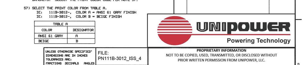
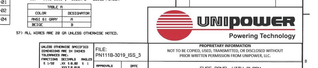
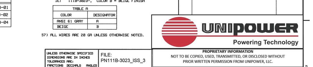
16 ED B1 Issue ISSUES ISSUE DESCRIPTION ISS. BY # ISS. DATE 4 SEE PCO# WD A A 51. SELECT THE PAINT COLOR PER TABLE A. 52. THE ONLY FUSES PROVIDED ARE THE MAIN (15A), ALM (.5A), DIST FUSES FOR THE CC (1.3A & 2A LOC #20), AND DIST FUSES FOR THE IC (.5A & 5A LOC #19). ALL OTHER DIST FUSES ALONG WITH THEIR DESIGNATION PINS MUST BE ORDERED SEPARATELY. ORDER PER TABLE B. 53. HOLES ABOVE GMT FUSE HOLDERS ARE FOR DESIGNATION PINS ALL WIRING IS 20 GA UNLESS OTHERWISE SPECIFIED INSTALL ALL FUSES AND COLOR DESIGNATION PINS ON FUSE POSITION 19, 20 AND 21 AS SPECIFIED APPLY HEATSHRINK SO THAT FA TERMINAL AND EXPOSED WIRES ARE COVERED TO PREVENT POSSIBLE ELECTRICAL SHORTING. 54. RELAY CONTACTS ARE RATED 2 AMP RESISTIVE AT 12-24VDC, 1 AMP AT 48VDC AND.5 AMP AT 120VDC. B B C COLOR ANSI 61 GRAY BEIGE DESIGNATOR A B TYPE "GMT" FUSES AMPS PART NUMBER COLOR PART NUMBER (FUSE) (PIN DESIG) RED WHITE ORANGE BLUE GREEN UNLESS OTHERWISE SPECIFIED DIMENSIONS ARE IN INCHES ± TOLERANCES ON: HOLES FRACTIONS DECIMALS (XX) DECIMALS (XXX) ANGLES ±1/32 ±0.020 ±0.010 ±1/2 SQUARE CORNERS AND ANGLES ARE 90 UNLESS OTHERWISE SPECIFIED. WORKMANSHIP: PER SPEC ENG032 MATERIAL: FINISH: CHECKED PKD 2/21/90 APPROVED ES 4/19/90 APPROVED APPROVALS DATE DRAWN GLD 2/21/90 C DUMMY PROPRIETARY INFORMATION NOT TO BE COPIED, USED, TRANSMITTED, OR DISCLOSED WITHOUT PRIOR WRITTEN PERMISSION FROM UNIPOWER, LLC. SHEET INDEX SH NO D ISSUE FUSE PANEL: SENSE/CONTROL D SIZE DOC TYPE / NUMBER ISSUE SCALE: N/A SHEET: 1 OF 3 FILE NAME: _SHT_1_ISS_4 4
17
18
19 PROPRIETARY INFORMATION NOT TO BE COPIED, USED, TRANSMITTED, OR DISCLOSED WITHOUT PRIOR WRITTEN PERMISSION FROM UNIPOWER, LLC. THE ISSUE OF SHEET 1REFLECTS THE LATEST ISSUE OF THE DRAWING SET. WHEN THE DRAWING SET IS REVISED, ONLY THE ISSUE NUMBERS OF MODIFIED SHEETS ARE CHANGED. THE ISSUE NUMBERS OF UNMODIFIED SHEETS ARE NOT CHANGED.
20
21
22
23 PROPRIETARY INFORMATION NOT TO BE COPIED, USED, TRANSMITTED, OR DISCLOSED WITHOUT PRIOR WRITTEN PERMISSION FROM UNIPOWER, LLC. THE ISSUE OF SHEET 1REFLECTS THE LATEST ISSUE OF THE DRAWING SET. WHEN THE DRAWING SET IS REVISED, ONLY THE ISSUE NUMBERS OF MODIFIED SHEETS ARE CHANGED. THE ISSUE NUMBERS OF UNMODIFIED SHEETS ARE NOT CHANGED.
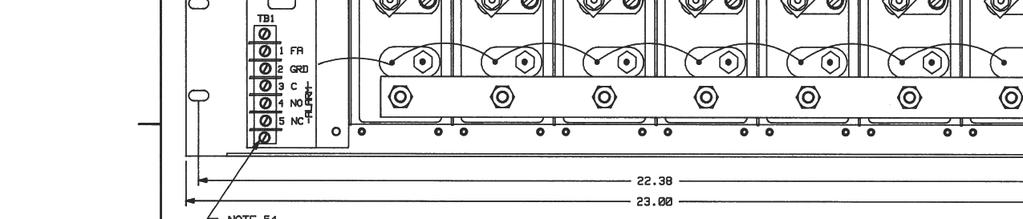
24 ED B3 Issue A LABEL HOLDER (NOTE 102) A [F5] [F7] [F9] [F11] 1.50" [F1] [F2] [F3] [F4] [F13] [F6] [F15] [F8] [F17] [F10] [F12] [F19] FA 2.25" 0.406" DIA., 2 PLC's 3.78" [F14] [F16] [F18] [F20] 5.25" NOTE 52 B 22.38" 6.00" 1.00" B 23.00" 7.625" ALARM FUSE (NOTES 51,105) MAIN FUSE (INSIDE), (NOTE 51) SHUNT (NOTE 55) C [F12] [F11] [F10] [F9] [F8] [F7] [F6] [F5] [F4] [F3] [F2] [F1] C A G A G A G A G NOTE 54 [R1] A G A G A G A G [F20] [F19] [F18] [F17] [F16] [F15] [F14] [F13] D PROPRIETARY INFORMATION NOT TO BE COPIED, USED, TRANSMITTED, OR DISCLOSED WITHOUT PRIOR WRITTEN PERMISSION FROM UNIPOWER, LLC. SIZE. DOC TYPE / NUMBER ISSUE PN D SCALE: SHEET: FILE NAME: NONE 2 OF 4 PN _SHT_2_ISS_4 4
25 ED B3 Issue A A NOTE 101 B NOTES 53, NOTES 53, B C C TO AMMETER BAT R1 NOTES 55,59 F1 F21 F4 F24 F5 F A 0-5A 20GA LOAD (OUTPUT) D PROPRIETARY INFORMATION NOT TO BE COPIED, USED, TRANSMITTED, OR DISCLOSED WITHOUT PRIOR WRITTEN PERMISSION FROM UNIPOWER, LLC. SIZE. DOC TYPE / NUMBER ISSUE PN D SCALE: SHEET: FILE NAME: NONE 3 OF 4 PN _SHT_3_ISS_4 4
26 ED B3 Issue A B LINE # NOTES DESCRIPTION PART NUMBERS FUSE PANEL: 4 NON, 8 DUAL TYPE 70, FA, 5.25" x 23" BUS BAR: FUSE TO SHUNT, 8, 30/60A BUS BAR: FUSE PANEL, INPUT TO SHUNT BUS BAR: 4 NON INPUT BUS BAR: 4 NON BUS BAR: DUAL TYPE 70 INPUT, 4 EA SIDE SCREW: STL, SEMS, 6-32 x 3/8" PHIL P/HD SCREW: STL, SEMS, 6-32 x 1/2" PHIL P/HD SCREW: STL, IND HEX HD SEMS, 1/4 x 1/2", ZINC BOLT, HEX, SIL, BRONZE: 3/8-16 x 3/4" NUT, HEX STL: 6-32, 5/16", KEPS NUT, HEX SS: 1/ NUT, HEX SS: 3/ WASHER, FLAT SS: 1/4" US STD WASHER, FLAT SS: 3/8" US STD WASHER, BELLEVILLE, SS: 1/4 x.500" WASHER, BELLEVILLE, SS: 3/8 x.750" SPACER: HEATSINK, HEX FIBREGLASS, 1.25" LABEL: 1-22 TYPE LABEL: FUSE 1 THRU FUSE FUSE HOLDER: DUAL FUSE HOLDER: 30 AMP FUSE "DUMMY":.25" x 1.25" TYPE ASSY: ALARM BOARD, BKT, LABEL, FOR FA RES, SHUNT: METER, 200A 50mV QUANTITY -00 QUANTITY A B C C 30 D PROPRIETARY INFORMATION NOT TO BE COPIED, USED, TRANSMITTED, OR DISCLOSED WITHOUT PRIOR WRITTEN PERMISSION FROM UNIPOWER, LLC. SIZE. DOC TYPE / NUMBER ISSUE PN D SCALE: SHEET: FILE NAME: NONE 4 OF 4 PN _SHT_4_ISS_2 4
 2/6/15 DBW 111-3051-10_ISS_2")

27 2 1 SEE ECN (WD 2/6/15) 2/6/15 DBW _ISS_2 PROPRIETARY INFORMATION NOT TO BE COPIED, USED, TRANSMITTED, OR DISCLOSED WITHOUT PRIOR WRITTEN PERMISSION FROM UNIPOWER, LLC. 2
28
29 PROPRIETARY INFORMATION NOT TO BE COPIED, USED, TRANSMITTED, OR DISCLOSED WITHOUT PRIOR WRITTEN PERMISSION FROM UNIPOWER, LLC.
30
31
32 PROPRIETARY INFORMATION NOT TO BE COPIED, USED, TRANSMITTED, OR DISCLOSED WITHOUT PRIOR WRITTEN PERMISSION FROM UNIPOWER, LLC.
33
34
35 PROPRIETARY INFORMATION NOT TO BE COPIED, USED, TRANSMITTED, OR DISCLOSED WITHOUT PRIOR WRITTEN PERMISSION FROM UNIPOWER, LLC. THE ISSUE OF SHEET 1REFLECTS THE LATEST ISSUE OF THE DRAWING SET. WHEN THE DRAWING SET IS REVISED, ONLY THE ISSUE NUMBERS OF MODIFIED SHEETS ARE CHANGED. THE ISSUE NUMBERS OF UNMODIFIED SHEETS ARE NOT CHANGED.
36
37
38
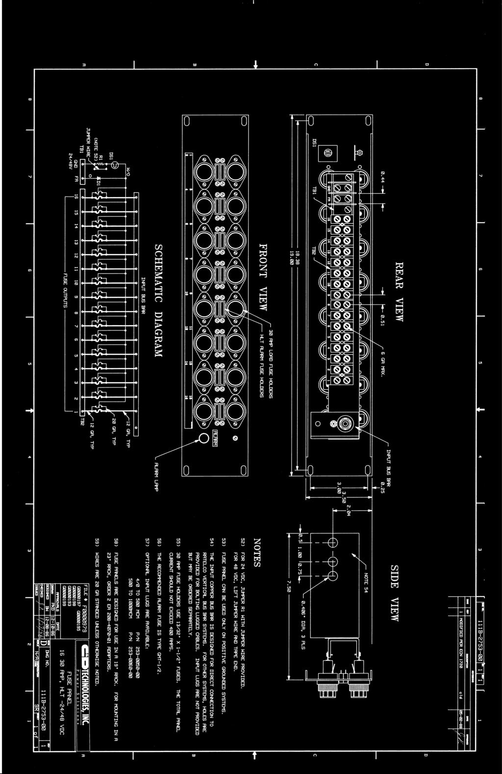
39 ED B1 Issue ISSUES ISSUE DESCRIPTION ISS. BY # ISS. DATE A 51. STANDARD WIRING IS FOR 48 VDC, FOR 24 VDC, REMOVE SLEEVING FROM JUMPER WIRE, SHORT ACROSS R1 AS SHOWN, AND SOLDER BACK. TO CONVERT FROM 24 VDC TO 48 VDC LIFT JUMPER WIRE AND TAPE END. 52. FUSE PANEL CAN BE USED ON POSITIVE OR NEGATIVE GROUNDED SYSTEMS ALL WIRING IS 20 GA UNLESS OTHERWISE SPECIFIED LOOP RESISTOR LEAD AS SHOWN, SOLDER WIRE TO LOOP SHEATH LUG ON FREE END OF JUMPER, AND TIE WRAP TO WIRE BUNDLE. 7 SEE PCO# WD 6/27/17 A 53. INPUTS A AND B MUST BE SUPPLIED FROM A COMMON SOURCE, 30A MAX PER SECTION. 54. MOUNTING BRACKETS ARE ADJUSTABLE FOR 19" OR 23" RACKS AND SEVERAL PANEL OFFSET DISTANCES. 55. RELAY CONTACTS ARE RATED 2 AMP RESISTIVE AT VDC, 1 AMP AT 48 VDC AND 0.5 AMP AT 120 VDC. COLOR DESIGNATOR TYPE "GMT" FUSES B 56. SELECT THE PAINT COLOR FROM TABLE A. IE: 111B , COLOR A = ANSI 61 GRAY FINISH IE: 111B , COLOR B = BEIGE FINISH 57. ORDER FUSES FROM TABLE B. ANSI 61 GRAY BEIGE A B AMPS PART NUMBER B DUMMY C NOMENCLATURE LABEL, GROUP A GROUP B FUSE ALARM 0.250" x 0.500" OBR 4 PLS UNLESS OTHERWISE SPECIFIED DIMENSIONS ARE IN INCHES ± TOLERANCES ON: HOLES FRACTIONS DECIMALS (XX) DECIMALS (XXX) ANGLES ±1/32 ±0.020 ±0.010 ±1/2 SQUARE CORNERS AND ANGLES ARE 90 UNLESS OTHERWISE SPECIFIED. WORKMANSHIP: PER SPEC ENG032 MATERIAL: CHECKED VBM 3/13/91 APPROVED PKD 4/19/91 APPROVED APPROVALS DATE DRAWN BW 8/28/85 C FINISH: PROPRIETARY INFORMATION NOT TO BE COPIED, USED, TRANSMITTED, OR DISCLOSED WITHOUT PRIOR WRITTEN PERMISSION FROM UNIPOWER, LLC. D SHEET INDEX SH NO 1 2 ISSUE 7 6 SIZE FUSE PANEL 24GMT, 24/48VDC, 60A MAX DOC TYPE / NUMBER 111B ISSUE 7 D SCALE: N/A SHEET: 1 OF 2 FILE NAME: 111B _SHT_1_ISS_
40
41
42

43
44
45
46
47
48 PROPRIETARY INFORMATION NOT TO BE COPIED, USED, TRANSMITTED, OR DISCLOSED WITHOUT PRIOR WRITTEN PERMISSION FROM UNIPOWER, LLC.
49
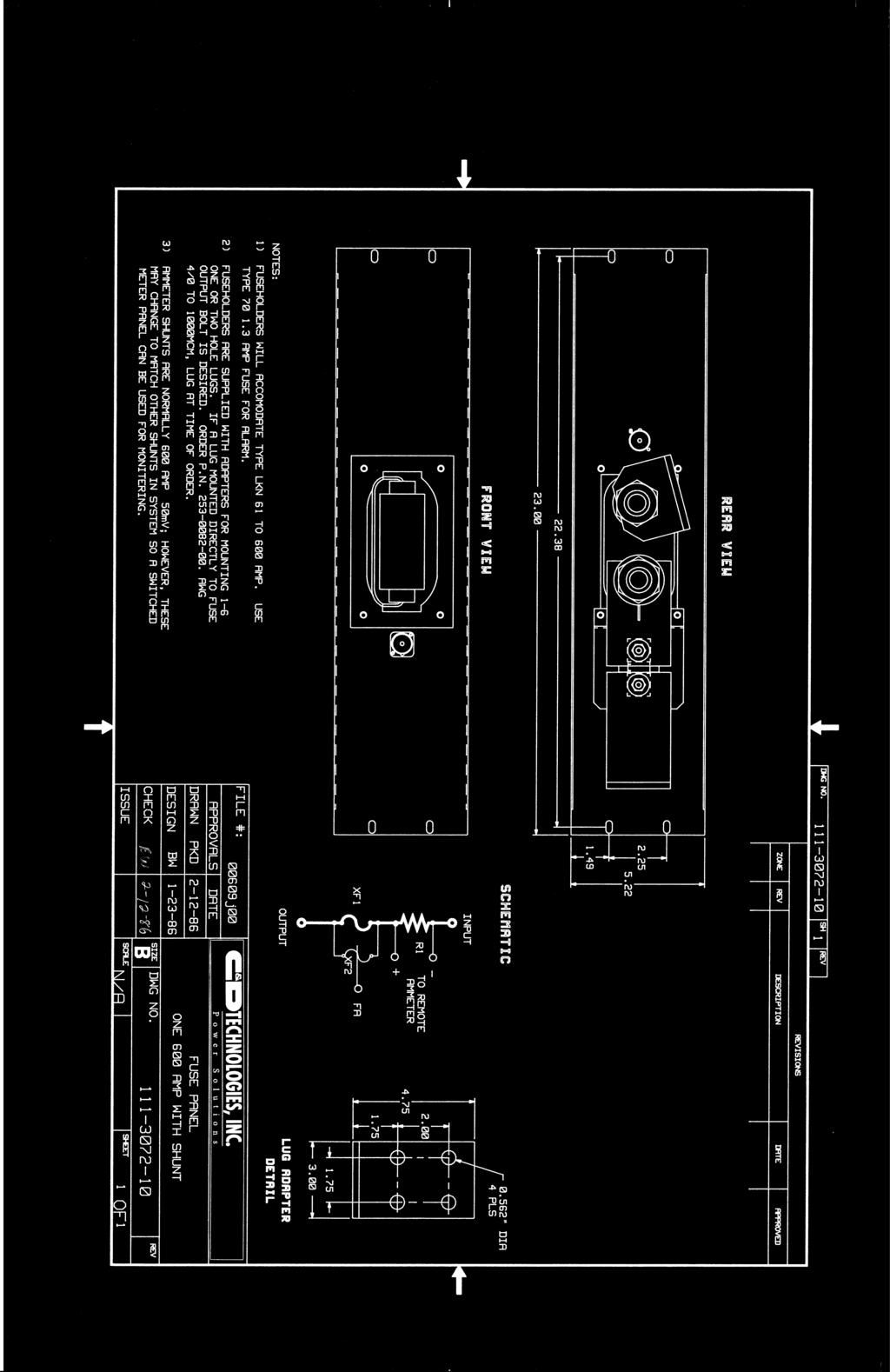
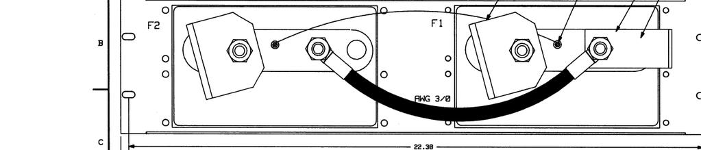
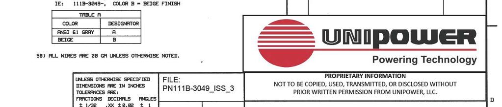
50 ED B1 Issue ISSUES ISSUE DESCRIPTION ISS. BY # ISS. DATE 5 SEE PCO# WD 6/27/17 A A NOTE 54 NOTE 53 NOTE INDICATING FUSE NOTE " X 0.50" OBR 4 PLC'S 0.281" DIA, 2 PLC'S F1 F2 F3 F4 F5 F6 F7 F8 F9 F10 F11 F12 F13 F14 F15 F16 F17 F18 F19 F20 F21 F22 B B C 51. UNASSIGNED 52. FUSE PANEL IS RATED FOR A MAX OF 60A AND WILL ACCOMMODATE TWENTY-TWO 0-5A TYPE 70 INDICATING FUSES. FUSES ARE NOT INCLUDED BUT MAY BE ORDERED SEPARATELY, PER ED THE INPUT COPPER BUS BAR IS DESIGNED FOR DIRECT CONNECTION TO THE VERTICAL BUS BAR SYSTEMS. FOR OTHER SYSTEMS, HOLES ARE PROVIDED FOR BOLTING LUGGED CABLES. INPUT LUGS ARE NOT PROVIDED BUT MAY BE ORDERED SEPARATELY, PER ED BAG LABELS AND PLASTIC COVERS. TIE WRAP TO INPUT BUS. (NOTE 55) FA 0 20GA INPUT BUS BAR BAT UNLESS OTHERWISE SPECIFIED DIMENSIONS ARE IN INCHES ± TOLERANCES ON: HOLES FRACTIONS DECIMALS (XX) DECIMALS (XXX) ANGLES ±1/32 ±0.020 ±0.010 ±1/2 SQUARE CORNERS AND ANGLES ARE 90 UNLESS OTHERWISE SPECIFIED. WORKMANSHIP: PER SPEC ENG032 MATERIAL: FINISH: CHECKED APPROVED BW 3/19/86 APPROVED APPROVALS DATE DRAWN SAN 3/19/86 C 54. OUTPUT LOAD WIRES CAN BE ATTACHED TO THE FUSE OUTPUT POSTS BY WIRE WRAPPING OR SOLDERING. 55. THE FUSE ALARM SIGNAL CAN BE EXTENDED TO A SEPARATE ALARM SYSTEM. CONNECT ALARM WIRE TO FUSE ALARM POST BY WIRE WRAPPING OR SOLDERING. LOADS F1 F2 F22 PROPRIETARY INFORMATION NOT TO BE COPIED, USED, TRANSMITTED, OR DISCLOSED WITHOUT PRIOR WRITTEN PERMISSION FROM UNIPOWER, LLC. D 56. SELECT THE PAINT COLOR FROM TABLE A: IE. 111B , COLOR A = ANSI 61 GRAY FINISH IE. 111B , COLOR B = BEIGE FINISH COLOR ANSI 61 GRAY BEIGE DESIGNATOR A B SIZE SCALE: N/A DOC TYPE / NUMBER PN FUSE PANEL 22 TYPE 70 ± 12V TO 130V SHEET: 1 OF 1 111B FILE NAME: PN111B _ISS_5 4 ISSUE 5 D
51
52
53
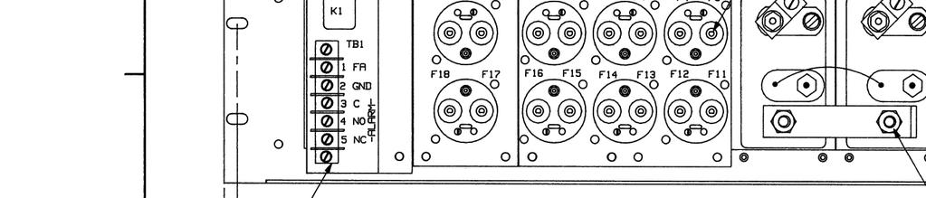
54 ED B1 Issue ISSUES 51. ORDER FUSE PANEL PER TABLE A. ISSUE # DESCRIPTION ISS. BY ISS. DATE 4 SEE PCO# WD 6/27/17 A VOLTS MODEL NUMBER ± 12V 111B ± 24V 111B ± 48V 111B ANSI 61 GRAY FINISH BEIGE COLOR DESIGNATOR A B A 52. THE INPUT COPPER BUS BAR IS DESIGNED FOR DIRECT CONNECTION TO VERTICAL BUS BAR SYSTEMS. FOR OTHER SYSTEMS, HOLES ARE PROVIDED FOR BOLTING LUGGED CABLES. INPUT LUGS ARE NOT PROVIDED, BUT MAY BE ORDERED SEPARATELY PER ED EACH DEADFRONT FUSEHOLDER REQUIRES ONE MAIN AND ONE ALARM FUSE. MAIN FUSES ARE TYPE NON OR TPN 1-30 AMPS. THE RECOMMENDED TYPE 70 ALARM FUSE IS 0.5 AMPS. FUSES ARE NOT INCLUDED, BUT MAY BE ORDERED SEPARATELY PER ED OUTPUT LUGS FOR CONNECTING THE LOAD CABLES ARE PROVIDED AND HAVE A WIRE RANGE OF 14-2 GA. B 54. AN ALARM ASSEMBLY IS INCLUDED. DURING A FUSE FAILURE A FRONT PANEL RED LAMP WILL LIGHT AND RELAY K1 WILL BE ENERGIZED. RELAY CONTACTS ARE RATED 2 AMPS AT 28VDC, 1 AMP AT 60VDC, AND 1/2 AMP AT 120VDC RESISTIVE. TERMINAL "FA" ON TB1 CAN BE USED TO EXTEND THE FUSE ALARM SIGNAL TO A SEPARATE ALARM SYSTEM. B 55. SELECT THE PAINT COLOR FROM TABLE B: IE. 111B-3014-, COLOR A = ANSI 61 GRAY FINISH. IE. 111B-3014-, COLOR B = BEIGE FINISH. C 101. ALL WIRE 20 GA. UNLESS OTHERWISE SPECIFIED BAG OUTPUT LUGS AND FUSE DESIGNATION LABELS, AND TIE WRAP TO INPUT BUS. TB1 FR 1 0 GRD 2 R DS1 RED 0 C1 1 4 K1 XK1 BAT INPUT BUS BAR F8 F9 F10 F11 F12 F13 F1 F2 F3 F4 F5 F6 F7 F14 UNLESS OTHERWISE SPECIFIED DIMENSIONS ARE IN INCHES ± TOLERANCES ON: HOLES FRACTIONS DECIMALS (XX) DECIMALS (XXX) ANGLES ±1/32 ±0.020 ±0.010 ±1/2 SQUARE CORNERS AND ANGLES ARE 90 UNLESS OTHERWISE SPECIFIED. WORKMANSHIP: PER SPEC ENG032 MATERIAL: APPROVED APPROVED APPROVALS DATE DRAWN PKD 8/29/86 CHECKED BW 8/22/86 C 7 TO LOADS FINISH: 6 FUSE ALARM RELAY C 3 NO 4 NC 5 BK BL Y PROPRIETARY INFORMATION NOT TO BE COPIED, USED, TRANSMITTED, OR DISCLOSED WITHOUT PRIOR WRITTEN PERMISSION FROM UNIPOWER, LLC. D THE ISSUE OF SHEET 1REFLECTS THE LATEST ISSUE SHEET INDEX OF THE DRAWING SET. WHEN THE DRAWING SET IS REVISED, ONLY THE ISSUE NUMBERS OF MODIFIED SHEETS ARE CHANGED. THE ISSUE NUMBERS OF UNMODIFIED SHEETS ARE NOT CHANGED. SH NO ISSUE SIZE FUSE PANEL 7 30A NON/TPN DOC TYPE / NUMBER PN 111B-3014 ISSUE 4 D SCALE: N/A SHEET: 1 OF 2 FILE NAME: PN111B-3014_SHT_1_ISS_4
55
56 ED B1 Issue (CONT'D) ISSUE DESCRIPTION ISSUES ISS. BY # ISS. DATE A 52. EACH DEADFRONT FUSE HOLDER REQUIRES ONE MAIN AND ONE ALARM FUSE. MAIN FUSES ARE TYPE NON OR TYPE TPN 0-30 AMPS. THE RECOMMENDED TYPE 70 ALARM FUSE IS 0.5 AMPS. FUSES ARE NOT INCLUDED BUT MAY BE ORDERED SEPARATELY PER EQUIPMENT DRAWING ED BUBBLE REFERENCE DESIGNATORS REFER TO CALLOUT TABLE LINE NUMBER, SHEET UNITS NOT EQUIPPED WITH A SHUNT DO NOT HAVE R1. UNITS NOT EQUIPPED WITH A FUSE ALARM ASSEMBLY DO NOT HAVE A1. 9 SEE PCO# WD 6/28/17 A B 53. THE INPUT COPPER BUS BAR IS DESIGNED FOR DIRECT CONNECTION TO VERTICAL BUS BAR SYSTEMS AND RATED FOR 400 AMPS MAX. FOR OTHER SYSTEMS, HOLES ARE PROVIDED FOR BOLTING LUGGED CABLES. INPUT LUGS ARE NOT PROVIDED BUT MAY BE ORDERED SEPARATELY PER EQUIPMENT DRAWING ED CRIMP LUGS MAY BE ATTACHED DIRECTLY TO FUSE-HOLDER STUDS. STUDS ARE 1/4"-20, WITH HARDWARE PROVIDED. COMPRESSION LUGS FOR CONNECTING LOAD CABLES ARE PROVIDED ON -00 AND -10 PANELS, AND HAVE A WIRE RANGE OF 14-2 GA. 55. A FUSE ALARM SIGNAL CAN BE EXTENDED TO A SEPARATE ALARM SYSTEM. 1) UNITS NOT EQUIPPED WITH A FUSE ALARM BOARD (-00,-10): CONNECT ALARM LEAD TO THE ALARM POST BY WIRE WRAPPING OR SOLDERING. 2) UNITS EQUIPPED WITH A FUSE ALARM BOARD (-13,-14): SEE SCHEMATIC DIAGRAM ON SHEET 3 FOR ALARM CONNECTION. FUSE ALARM SIGNALS CONNECT "BAT" TO THE ALARM CONNECTION WHEN A FUSE CLEARS. 56. AMMETER SHUNTS ARE NORMALLY 200 AMPS 50mV; HOWEVER, CURRENT RATINGS UP TO 600 AMPS MAY BE SPECIFIED. SEE FIGURE B2, SECTION B-B FOR SHUNT AND BUSWORK DETAILS. 57. PAINT COLOR IS ANSI 61 GRAY. 58. THE MAXIMUM RECOMMENDED OUTPUT WIRE SIZE IS 6 GA. LARGER WIRE SIZES WILL REQUIRE ADDITIONAL RACK SPACES AND CABLE SUPPORTS REPLACE THE BOLTS SUPPLIED WITH THE SHUNT WITH 3/8"-16 x 3/4" BOLTS, P/N PROPER BUS BAR ARRANGEMENT IS CRITICAL, SEE FIGURE B1 AND B2, SHEET PUT SUPPLIED OUTPUT LUGS AND FUSE HOLDER DESIGNA- TION TAGS IN A BAG AND TIE WRAP TO THE INPUT BUS BAR [ ] DENOTES THAT THE INFORMATION IS FOR REFERENCE ONLY A COMPOUND SUCH AS CRAMOLIN 81Rh WILL BE APPLIED TO ALL JOINTED, FLAT, CONDUCTIVE SURFACES PER THE MANU- FACTURER'S INSTRUCTIONS INSTALL DUMMY FUSE P/N IN ALARM FUSE HOLDERS ON XF1-8. UNLESS OTHERWISE SPECIFIED DIMENSIONS ARE IN INCHES ± TOLERANCES ON: HOLES FRACTIONS DECIMALS (XX) DECIMALS (XXX) ANGLES ±1/32 ±0.020 ±0.010 ±1/2 APPROVED APPROVED APPROVALS SQUARE CORNERS AND ANGLES ARE 90 UNLESS OTHERWISE SPECIFIED. DATE DRAWN PKD 10/6/86 CHECKED TET 10/6/86 B C TABLE A PART NUMBER VOLTAGE E/W SHUNT E/W FA BOARD FIGURES WORKMANSHIP: PER SPEC ENG032 MATERIAL: C 111B B ±12-130V NO YES NO NO A2,C2 A2,B2,C1 FINISH: 111B B , -48 NO YES YES YES A1,C2 A1,B1,C1 PROPRIETARY INFORMATION NOT TO BE COPIED, USED, TRANSMITTED, OR DISCLOSED WITHOUT PRIOR WRITTEN PERMISSION FROM UNIPOWER, LLC. D THE ISSUE OF SHEET 1REFLECTS THE LATEST ISSUE OF THE DRAWING SET. WHEN THE DRAWING SET IS REVISED, ONLY THE ISSUE NUMBERS OF MODIFIED SHEETS ARE CHANGED. THE ISSUE NUMBERS OF UNMODIFIED SHEETS ARE NOT CHANGED. SH NO ISSUE SHEET INDEX SIZE SCALE: N/A DOC TYPE / NUMBER PN 111B-3016 SHEET: 1 OF 4 FUSE PANEL 8, 0-30 AMP NON/TPN FILE NAME: PN111B-3016_SHT_1_ISS_9 4 ISSUE 9 D
57
58
59
60
61 PROPRIETARY INFORMATION NOT TO BE COPIED, USED, TRANSMITTED, OR DISCLOSED WITHOUT PRIOR WRITTEN PERMISSION FROM UNIPOWER, LLC. THE ISSUE OF SHEET 1REFLECTS THE LATEST ISSUE OF THE DRAWING SET. WHEN THE DRAWING SET IS REVISED, ONLY THE ISSUE NUMBERS OF MODIFIED SHEETS ARE CHANGED. THE ISSUE NUMBERS OF UNMODIFIED SHEETS ARE NOT CHANGED.
62
63
64
65
66 ED B1 Issue (CONT'D) ISSUE DESCRIPTION ISSUES ISS. BY # ISS. DATE 52. EACH DEADFRONT FUSE HOLDER REQUIRES ONE MAIN AND ONE ALARM FUSE. MAIN FUSES ARE TYPE NON OR TYPE TPN 0-30 AMPS. THE RECOMMENDED TYPE 70 ALARM FUSE IS 0.5 AMPS. FUSES ARE NOT INCLUDED BUT MAY BE ORDERED SEPARATELY PER EQUIPMENT DRAWING ED BUBBLE REFERENCE DESIGNATORS REFER TO CALLOUT TABLE LINE NUMBER, SHEET UNITS NOT EQUIPPED WITH A SHUNT DO NOT HAVE R1. UNITS NOT EQUIPPED WITH A FUSE ALARM ASSEMBLY DO NOT HAVE A1. 9 SEE PCO# WD 6/28/17 A 53. THE INPUT COPPER BUS BAR IS DESIGNED FOR DIRECT CONNECTION TO VERTICAL BUS BAR SYSTEMS AND RATED FOR 400 AMPS MAX. FOR OTHER SYSTEMS, HOLES ARE PROVIDED FOR BOLTING LUGGED CABLES. INPUT LUGS ARE NOT PROVIDED BUT MAY BE ORDERED SEPARATELY PER EQUIPMENT DRAWING ED CRIMP LUGS MAY BE ATTACHED DIRECTLY TO FUSE-HOLDER STUDS. STUDS ARE 1/4"-20, WITH HARDWARE PROVIDED. COMPRESSION LUGS FOR CONNECTING LOAD CABLES ARE PROVIDED ON -00 AND -10 PANELS, AND HAVE A WIRE RANGE OF 14-2 GA. 55. A FUSE ALARM SIGNAL CAN BE EXTENDED TO A SEPARATE ALARM SYSTEM. 1) UNITS NOT EQUIPPED WITH A FUSE ALARM BOARD (-00,-10): CONNECT ALARM LEAD TO THE ALARM POST BY WIRE WRAPPING OR SOLDERING. 2) UNITS EQUIPPED WITH A FUSE ALARM BOARD (-13,-14): SEE SCHEMATIC DIAGRAM ON SHEET 3 FOR ALARM CONNECTION. FUSE ALARM SIGNALS CONNECT "BAT" TO THE ALARM CONNECTION WHEN A FUSE CLEARS. 56. AMMETER SHUNTS ARE NORMALLY 200 AMPS 50mV; HOWEVER, CURRENT RATINGS UP TO 600 AMPS MAY BE SPECIFIED. SEE FIGURE B2, SECTION B-B FOR SHUNT AND BUSWORK DETAILS. 57. PAINT COLOR IS ANSI 61 GRAY. 58. THE MAXIMUM RECOMMENDED OUTPUT WIRE SIZE IS 6 GA. LARGER WIRE SIZES WILL REQUIRE ADDITIONAL RACK SPACES AND CABLE SUPPORTS REPLACE THE BOLTS SUPPLIED WITH THE SHUNT WITH 3/8"-16 x 3/4" BOLTS, P/N PROPER BUS BAR ARRANGEMENT IS CRITICAL, SEE FIGURE B1 AND B2, SHEET PUT SUPPLIED OUTPUT LUGS AND FUSE HOLDER DESIGNA- TION TAGS IN A BAG AND TIE WRAP TO THE INPUT BUS BAR [ ] DENOTES THAT THE INFORMATION IS FOR REFERENCE ONLY A COMPOUND SUCH AS CRAMOLIN 81Rh WILL BE APPLIED TO ALL JOINTED, FLAT, CONDUCTIVE SURFACES PER THE MANU- FACTURER'S INSTRUCTIONS INSTALL DUMMY FUSE P/N IN ALARM FUSE HOLDERS ON XF1-8. UNLESS OTHERWISE SPECIFIED DIMENSIONS ARE IN INCHES ± TOLERANCES ON: HOLES FRACTIONS DECIMALS (XX) DECIMALS (XXX) ANGLES ±1/32 ±0.020 ±0.010 ±1/2 APPROVED APPROVED APPROVALS SQUARE CORNERS AND ANGLES ARE 90 UNLESS OTHERWISE SPECIFIED. DATE DRAWN PKD 10/6/86 CHECKED BW 10/6/86 B TABLE A PART NUMBER VOLTAGE E/W SHUNT E/W FA BOARD FIGURES WORKMANSHIP: PER SPEC ENG032 MATERIAL: C 111B B ±12-130V NO YES NO NO A2,C2 A2,B2,C1 FINISH: 111B B , -48 NO YES YES YES A1,C2 A1,B1,C1 PROPRIETARY INFORMATION NOT TO BE COPIED, USED, TRANSMITTED, OR DISCLOSED WITHOUT PRIOR WRITTEN PERMISSION FROM UNIPOWER, LLC. THE ISSUE OF SHEET 1REFLECTS THE LATEST ISSUE OF THE DRAWING SET. WHEN THE DRAWING SET IS REVISED, ONLY THE ISSUE NUMBERS OF MODIFIED SHEETS ARE CHANGED. THE ISSUE NUMBERS OF UNMODIFIED SHEETS ARE NOT CHANGED. SH NO ISSUE SHEET INDEX SIZE SCALE: N/A DOC TYPE / NUMBER PN 111B-3025 SHEET: 1 OF 4 FUSE PANEL 8, AMP NON/TPN FILE NAME: PN111B-3025_SHT_1_ISS_9 ISSUE 9 D
67
68
69
70 ED B1 Issue ISSUES ISSUE DESCRIPTION ISS. BY # ISS. DATE A 51. UNASSIGNED. 52. EACH DEADFRONT FUSE HOLDER REQUIRES ONE MAIN AND ONE ALARM FUSE. MAIN FUSES ARE TYPE NON OR TPN 0-60 AMPS. THE RECOMMENDED TYPE 70 ALARM FUSE IS 0.5 AMPS. FUSES ARE NOT INCLUDED BUT MAY BE ORDERED SEPARATELY PER EQUIPMENT DRAWING ED THE INPUT COPPER BUS BAR IS DESIGNED FOR DIRECT CONNECTION TO VERTICAL BUS BAR SYSTEMS AND RATED FOR 400 AMPS MAX. FOR OTHER SYSTEMS, HOLES ARE PROVIDED FOR BOLTING LUGGED CABLES. INPUT LUGS ARE NOT PROVIDED BUT MAY BE ORDERED SEPARATELY PER EQUIPMENT DRAWING ED THE MAXIMUM RECOMMENDED OUTPUT WIRE SIZE IS 6 GA. LARGER WIRE SIZES WILL REQUIRE ADDITIONAL RACK SPACES AND CABLE SUPPORTS. 59. BUBBLE REFERENCE DESIGNATORS REFER TO CALLOUT TABLE LINE NUMBER, SHEET UNITS NOT EQUIPPED WITH A SHUNT DO NOT HAVE R1. UNITS NOT EQUIPPED WITH A FUSE ALARM ASSEMBLY DO NOT HAVE A1. 5 SEE PCO# WD 6/28/17 A B C 54. CRIMP LUGS MAY BE ATTACHED DIRECTLY TO FUSE-HOLDER STUDS. STUDS ARE 1/4"-20, WITH HARDWARE PROVIDED. COMPRESSION LUGS FOR CONNECTING LOAD CABLES ARE PROVIDED ON -00 AND -10 PANELS, AND HAVE A WIRE RANGE OF 14-2 GA. 55. A FUSE ALARM SIGNAL CAN BE EXTENDED TO A SEPARATE ALARM SYSTEM. 1) UNITS NOT EQUIPPED WITH A FUSE ALARM BOARD (-00,-10): CONNECT ALARM LEAD TO THE ALARM POST BY WIRE WRAPPING OR SOLDERING. 2) UNITS EQUIPPED WITH A FUSE ALARM BOARD (-13,-14): CONNECT THE ALARM LEAD TO THE "FA-OUT" TERMINAL ON XA1, IN POSITIVE GRD SYSTEMS OR TO THE "FA+OUT" TERMINAL, IN NEGATIVE SYSTEMS. FUSE ALARM SIGNALS CONNECT "BAT" TO THE ALARM CONNECTION WHEN A FUSE CLEARS. 56. AMMETER SHUNTS ARE NORMALLY 200 AMPS 50mV; HOWEVER, CURRENT RATINGS UP TO 600 AMPS MAY BE SPECIFIED. SEE FIGURE B2, SECTION B-B FOR SHUNT AND BUSWORK DETAILS. 57. PAINT COLOR IS ANSI 61 GRAY REPLACE THE BOLTS SUPPLIED WITH THE SHUNT WITH 3/8"-16 x 3/4" BOLTS, P/N PROPER BUS BAR ARRANGEMENT IS CRITICAL, SEE FIGURE B1 AND B2, SHEET PUT SUPPLIED OUTPUT LUGS AND FUSE HOLDER DESIGNA- TION TAGS IN A BAG AND TIE WRAP TO THE INPUT BUS BAR [ ] DENOTES THAT THE INFORMATION IS FOR REFERENCE ONLY A COMPOUND SUCH AS CRAMOLIN 81Rh WILL BE APPLIED TO ALL JOINTED, FLAT, CONDUCTIVE SURFACES PER THE MANU- FACTURER'S INSTRUCTIONS INSTALL DUMMY FUSE P/N IN ALARM FUSE HOLDERS ON XF1-8. UNLESS OTHERWISE SPECIFIED DIMENSIONS ARE IN INCHES ± TOLERANCES ON: HOLES FRACTIONS DECIMALS (XX) DECIMALS (XXX) ANGLES ±1/32 ±0.020 ±0.010 ±1/2 SQUARE CORNERS AND ANGLES ARE 90 UNLESS OTHERWISE SPECIFIED. WORKMANSHIP: PER SPEC ENG032 MATERIAL: APPROVED APPROVED APPROVALS DATE DRAWN PKD 10/6/86 CHECKED BW 10/28/86 B C TABLE A FINISH: PART NUMBER VOLTAGE E/W SHUNT E/W FA BOARD FIGURES 111B B ±12-130V ±12-130V NO YES NO NO A2,C2 A2,B2,C1 PROPRIETARY INFORMATION NOT TO BE COPIED, USED, TRANSMITTED, OR DISCLOSED WITHOUT PRIOR WRITTEN PERMISSION FROM UNIPOWER, LLC. 111B ±24,48 OR 130V NO YES A1,C2,D1 111B ±24,48 OR 130V YES YES A1,B1,C1,D1 D THE ISSUE OF SHEET 1REFLECTS THE LATEST ISSUE OF THE DRAWING SET. WHEN THE DRAWING SET IS REVISED, ONLY THE ISSUE NUMBERS OF MODIFIED SHEETS ARE CHANGED. THE ISSUE NUMBERS OF UNMODIFIED SHEETS ARE NOT CHANGED. SH NO ISSUE SHEET INDEX SIZE FUSE PANEL 4 EA, 30/60A, NON OR TPN 5.25" X 23" DOC TYPE / NUMBER PN 111B-3035 ISSUE 5 D SCALE: N/A SHEET: 1 OF 4 FILE NAME: PN111B-3035_SHT_1_ISS_
71
72
73
74
75
76
77 PROPRIETARY INFORMATION NOT TO BE COPIED, USED, TRANSMITTED, OR DISCLOSED WITHOUT PRIOR WRITTEN PERMISSION FROM UNIPOWER, LLC.
78
79
80
81 PROPRIETARY INFORMATION NOT TO BE COPIED, USED, TRANSMITTED, OR DISCLOSED WITHOUT PRIOR WRITTEN PERMISSION FROM UNIPOWER, LLC.
82
83
84
85 PROPRIETARY INFORMATION NOT TO BE COPIED, USED, TRANSMITTED, OR DISCLOSED WITHOUT PRIOR WRITTEN PERMISSION FROM UNIPOWER, LLC.
86
87
88
CEMF CELL PANEL PRODUCT MANUAL
 CEMF CELL PANEL PRODUCT MANUAL This manual applies to the following panels: 111-3200-00 111B-3216-00 111B-3217-00 111B-3218-00 111B-3219-00 111B-3219-01 PM990-3200-00, Issue 8 UNIPOWER, LLC 3900 Coral
Fuse Panels, Fuse Holders and Fuses
 DC Power Systems for Business-Critical Continuity Fuse Panels, Fuse Holders and Fuses 23" (58.42cm) Fuse Panels Description of Panels E/W Fuse Positions and Accessories Fuse Type Fuse Table Panel Height
PEC 5068 BDFB 1-10 Loads, 500A Max/Load -48V, 2000A Max Load/Bay
 PEC 5068 BDFB 1-10 Loads, 500A Max/Load -48V, 2000A Max Load/Bay Product Manual Part Number: 438 5068PD Issue 32, March 2010 Engineer: H. D. Approved: H. D. PECO II, Inc. 1376 State Route 598 Galion, OH
Operation Manual. For the. Sageon Battery Monitor
 Operation Manual For the Sageon Battery Monitor PM 990420900, Issue 6 UNIPOWER, LLC 3900 Coral Ridge Drive Coral Springs, FL 33065 Phone: 19543462442 Toll Free: 18004403504 Web site http://www.unipowerco.com
FUSE PANEL Technical Practice N N-L34 20/20 GMT (23 panel) NEBS Level 3 Certified
 NEBS Level 3 Certified") 530-101732 Rev L 0223-03K September 30, 2010 Westell FUSE PANEL Technical Practice N250140-N-L34 20/20 GMT (23 panel) NEBS Level 3 Certified FEATURES 2 isolated groups (busses) of 20 GMT fuses each (15Amps/GMT
530-101732 Rev L 0223-03K September 30, 2010 Westell FUSE PANEL Technical Practice N250140-N-L34 20/20 GMT (23 panel) NEBS Level 3 Certified FEATURES 2 isolated groups (busses) of 20 GMT fuses each (15Amps/GMT
Noran Tel. Fuse Panel Technical Practice N NCY 4/4TPA & 6/6 GMT NEBS Level 3 Certified
 0406-03E August 11, 2005 Fuse Panel Technical Practice N215120-NCY 4/4TPA & 6/6 GMT NEBS Level 3 Certified FEATURES Compatible with +24V, +48V, -24V or -48V dc input voltages (battery voltages). 2 busses
Fuse Panels, Fuse Holders and Fuses
 Fuse Panel Assembly 23" (8.42cm) FUSE Description of Panels E/W Fuse Positions and Accessories Fuse Type PANELS Fuse Table Fuse Cabinet Assembly Panel Height 4316000 ( 4) 0- A, (16) Additional Positions
Noran Tel. FUSE PANEL Technical Practice N21C110-NCY 5/5 GMT (20Amp GMT) NEBS Level 3 Certified
 NEBS Level 3 Certified") 0322-03D Sept 02, 2010 Noran Tel FUSE PANEL Technical Practice N21C110-NCY 5/5 GMT (20Amp GMT) NEBS Level 3 Certified FEATURES 2 isolated groups (busses) of 5 GMT fuses each (20Amps/GMT position). Polarity
0322-03D Sept 02, 2010 Noran Tel FUSE PANEL Technical Practice N21C110-NCY 5/5 GMT (20Amp GMT) NEBS Level 3 Certified FEATURES 2 isolated groups (busses) of 5 GMT fuses each (20Amps/GMT position). Polarity
DS1 Plug-In Digital Signal Cross-Connect (PIX-DSX-1) 19-Inch Shelf Kit Installation Instructions
 19-Inch Shelf Kit Installation Instructions") DS Plug-In Digital Signal Cross-Connect (PIX-DSX-) 9-Inch Shelf Kit Installation Instructions Contents Page INTRODUCTION... Revision History... List of Changes... Trademark Information... Related Publications...2
DS Plug-In Digital Signal Cross-Connect (PIX-DSX-) 9-Inch Shelf Kit Installation Instructions Contents Page INTRODUCTION... Revision History... List of Changes... Trademark Information... Related Publications...2
FUSE PANEL. Technical Practice N N-L33 10/10 GMT Front Access NEBS Level 3 Certified
 530-063 Rev K 0220-03K November 3, 202 Westell FUSE PANEL Technical Practice N25020-N-L33 0/0 GMT Front Access NEBS Level 3 Certified FEATURES 2 isolated groups (busses) of 0 GMT fuses in each (5Amps/GMT
FUSE PANEL. NTI-N NC(Y)/M3 NEBS Level 3 Certified NTI NCD(Y)/M3 Standard Panel with Diodes
/M3 NEBS Level 3 Certified NTI NCD(Y)/M3 Standard Panel with Diodes") 0113-03K September 2, 2010 FUSE PANEL Technical Practice NTI-N250140-NC(Y)/M3 NEBS Level 3 Certified NTI-230140-NCD(Y)/M3 Standard Panel with Diodes FEATURES ƒ Negative (-) VDC input voltage, -24 or 48Vdc
0113-03K September 2, 2010 FUSE PANEL Technical Practice NTI-N250140-NC(Y)/M3 NEBS Level 3 Certified NTI-230140-NCD(Y)/M3 Standard Panel with Diodes FEATURES ƒ Negative (-) VDC input voltage, -24 or 48Vdc
INSTRUCTION MANUAL FOR PC63 CAGE
 INSTRUCTION MANUAL FOR PC63 CAGE CPN106833 ISSUE DATE: 15689-12/02 ECN/DATE 106 BRADROCK DRIVE DES PLAINES, IL. 60018 (847) 299-1188 FAX: (847) 299-3061 16816-6/05 INSTRUCTION DRAWING NUMBER: P25-LPC63-1
 10-32 x 1/2" PAN HEAD BOLT 14 PLACES, 7 PER BRACKET # 10/12 GROUND WASHER 2 PLACES, 1 PER BRACKET # 10 FLAT WASHER 12 PLACES, 6 PER BRACKET BRACKET, P/N 520295 2 PLACES RIGHT SIDE VIEW (LEFT SIDE SIMILAR)
MODEL A97 SERIES. Switchmode Utility Rectifier/Battery Charger ECN/DATE
 MODEL A97 SERIES Switchmode Utility Rectifier/Battery Charger CPN108172 ISSUE DATE: 16071 7/03 ECN/DATE 106 BRADROCK DRIVE DES PLAINES, IL. 60018-1967 (847) 299-1188 FAX: (847)299-3061 Page 1 of 7 INSTRUCTION
DC Distribution Panel User Guide # S
 DC Distribution Panel User Guide # S2-61256-100 68-11926-100 Standard Limited Hardware Warranty LIMITED WARRANTY. Equipment manufactured by CTI Products, Inc. is warranted to be free from defects in material
Shelf 19 version) (Expansion Shelf 19 version) (Main Shelf 23 version) (Expansion Shelf 23 version)
 (Expansion Shelf 19 version) (Main Shelf 23 version) (Expansion Shelf 23 version)") SYSTEM OVERVIEW Description: +24VDC to -48VDC @ up to 375A converter system. The NetSure DCS48375 Converter System is comprised of a main shelf and up to two (2) expansion shelves. Each shelf provides
SYSTEM OVERVIEW Description: +24VDC to -48VDC @ up to 375A converter system. The NetSure DCS48375 Converter System is comprised of a main shelf and up to two (2) expansion shelves. Each shelf provides
FUSE PANEL Technical Practice FDP /10 GMT NEBS Level 3 Certified
 0521-03A May 2006 FUSE PANEL Technical Practice FDP 1010 10/10 GMT NEBS Level 3 Certified FEATURES 2 isolated groups (busses) of 10 GMT fuses in each (15Amps/GMT position) Polarity insensitive (+/-24 or
40A A 40B. Horn Relay Connector. Brake Switch. Third Brake Light. Brake Switch. Brake Switch. Wires. page 3. Rear Body Feed Wires.
 Fuse Box Connections (viewed from underside) 4D 4C 4D 0 50 300 4C 43 7 39 3 6 4 93 A 2G 2F 2E 2D 2C 2B 2G 2F 2E 40 69A 2 1 5 27 69A 3A B 40A,B 11A,B 40A 156 Dimmer Dome Feed page 2 Horn Relay 2D 2 29 40B
INSTRUCTIONS Circuit Wiring Kit Instructions _2017. Fuse Box Connections. (viewed from underside) 2018, Speedway Motors, Inc.
 2018, Speedway Motors, Inc.") Fuse Box Connections (viewed from underside) 4D 4C 100 50 300 4D 4C 4B 4A 43 107 39 103 3B 2G 104 93 2F 2E 2D 2C 2B 40 69A 102 101 105 2G 2F 2E 3A A 2A B 40A,B 27 69A 106 201, Speedway Motors, Inc. 1 Fuse
Fuse Box Connections (viewed from underside) 4D 4C 100 50 300 4D 4C 4B 4A 43 107 39 103 3B 2G 104 93 2F 2E 2D 2C 2B 40 69A 102 101 105 2G 2F 2E 3A A 2A B 40A,B 27 69A 106 201, Speedway Motors, Inc. 1 Fuse
A48 / A48B (base plate) BATTERY CHARGER
 BATTERY CHARGER") A48 / A48B (base plate) BATTERY CHARGER CPN41054 ISSUE DATE: 12315-8/98 ECN/DATE 106 BRADROCK DRIVE DES PLAINES, IL. 60018-1967 (847) 299-1188 FAX: (847)299-3061 15349-07-07/02 16041 6/03 14575-2/01 INSTRUCTION
A48 / A48B (base plate) BATTERY CHARGER CPN41054 ISSUE DATE: 12315-8/98 ECN/DATE 106 BRADROCK DRIVE DES PLAINES, IL. 60018-1967 (847) 299-1188 FAX: (847)299-3061 15349-07-07/02 16041 6/03 14575-2/01 INSTRUCTION
INSTRUCTIONS 12 Circuit Wiring Kit Instructions
 Fan 47 9 56 4 7 6 72 40 45 48 5 8 6 Gauge Power Temp Sender Headlight Power Power Radio Constant Power Instruments and Dash Rear of Vehicle Ignition and Lights Fuse Panel & Front of Vehicle Horn Alt Excitor
TO AVOID DOING IRREPARABLE DAMAGE TO DRIVE CIRCUITRY NEVER APPLY AC POWER DIRECTLY TO LED LIGHTBOXES!
 INSTALLATION MANUAL TO AVOID DOING IRREPARABLE DAMAGE TO DRIVE CIRCUITRY NEVER APPLY AC POWER DIRECTLY TO LED LIGHTBOXES! 4949 South 110 th Street Greenfield, WI 53228 Phone: (800) 610-6053 Fax: (414)
SX-16 Nightsun Searchlight Safety and Service Bulletin # SL
 SX-16 Nightsun Searchlight Safety and Service Bulletin # SL0600-01 Issued Date: 06/22/00 Amended Date: 01/13/2010 WARNING: TO AVOID A POTENTIALLY DANGEROUS SITUATION WHICH COULD CAUSE PROPERTY DAMAGE AND
Dual 100A 4/4-KLM & 4/4-GMT Fuse Panel. Model N Installation Guide
 Dual 100A 4/4-KLM & 4/4-GMT Fuse Panel Model 009-8004-0100N Installation Guide Dual 100A 4/4-KLM & 4/4-GMT Fuse Panel Model 009-8004-0100N Installation Guide, Part Number 123759-3 Copyright 2011, Telect,
Westell FUSE PANEL. Technical Practice N Position Type VDC Floating
 530-101760 REV C 0808-03C December 7, 2012 Westell FUSE PANEL Technical Practice 180108-N-0808 8 Position Type 70 130 VDC Floating FEATURES Single floating input distributing power via Type-70 fuses each
Junior Sandblaster. Model #51 WARNING! FOR YOUR SAFETY PLEASE READ INSTRUCTIONS BEFORE OPERATING TOOL & WEAR EYE PROTECTION
 Junior Sandblaster Model #51 WARNING! FOR YOUR SAFETY PLEASE READ INSTRUCTIONS BEFORE OPERATING TOOL & WEAR EYE PROTECTION PARTS LIST AND PART NUMBERS 01.Red Rubber Air Hose (5Ft) P51-01 02. Male Insert
Noran Tel. a subsidiary of Westell Inc. Fuse Panel Technical Practice NPGMT /10 GMT NEBS Level 3 Verified
 1107-03B Aug 16, 2011 a subsidiary of Westell Inc Fuse Panel Technical Practice NPGMT1107 10/10 GMT NEBS Level 3 Verified FEATURES 2 isolated groups (busses) of 10 GMT style fuses in each (20Amps/GMT position
Crestron TTK-MP/MPC/IPAC & SMK-MP/MPC/IPAC TableTop and Swivel Mount Kits Installation Guide
 Crestron TTK-MP/MPC/IPAC & SMK-MP/MPC/IPAC TableTop and Swivel Mount Kits Installation Guide This document was prepared and written by the Technical Documentation department at: Industry Compliance As
Dimensions 12/800N 12/1200N D. DC to AC Power Inverters. OWNERS MANUAL for Models: OWNERS MANUAL April ISO 9001:2000 Certified Company
 Manufacturer of Dimensions Inverters 4467 White Bear Parkway St. Paul, MN 55110 Phone: 651-653-7000 Fax: 651-653-7600 E-mail: inverterinfo@sensata.com Web: www.dimensions.sensata.com OWNERS MANUAL April
FUSE PANEL Technical Practice FDP /20 GMT NEBS Level 3 Certified
 0522-03A May 2006 FUSE PANEL Technical Practice FDP 2020 20/20 GMT NEBS Level 3 Certified FEATURES Polarity insensitive (+/-24 or +/-48 Vdc) battery voltage This panel can operate at 200 Amps of output
Countertop B.I.B. Butter Dispenser Instruction Manual Model #2496
 Part No. 39177 Countertop B.I.B. Butter Dispenser Instruction Manual Cincinnati, OH 45241-4807 USA SAFETY PRECAUTIONS Installation Instructions Countertop B.I.B. Checking Shipment Unpack all cartons and
Manual No: Revision: B. CCVP Rain Shield. Installation Guide
 Manual No: 577013-978 Revision: B CCVP Rain Shield Installation Guide Notice Veeder-Root makes no warranty of any kind with regard to this publication, including, but not limited to, the implied warranties
Disconnect Combiner Box Installation Manual
 Disconnect Combiner Box Installation Manual SolarBOS, Inc. 310 Stealth Court Livermore CA 94551-9552 925-456-7744 ph. 925-456-7710 fax www.solarbos.com Copyright 2008 SolarBOS, Inc. All rights reserved.
TRINETICS CSD SERIES OIL SWITCH INSTALLATION INSTRUCTIONS
 TRINETICS CSD SERIES OIL SWITCH INSTALLATION INSTRUCTIONS 33220900 DECEMBER 2011 Caution: The equipment covered by these installation instructions should be installed and serviced only by properly trained
CIVACON GROUND VERIFICATION RACK MONITOR SYSTEM and ASSOCIATED EQUIPMENT
 GROUND VERIFICATION RACK MONITOR SYSTEM and ASSOCIATED EQUIPMENT INSTALLATION AND WIRING INSTRUCTIONS MANUAL 8030 MANUAL PART NUMBER JANUARY 2011. 4304 MATTOX RD. KANSAS CITY, MO 64150 TABLE OF CONTENTS
BR62 Battery Rack Installation, Operation, & Maintenance Manual
 BR62 Battery Rack Installation, Operation, & Maintenance Manual 8/28/2012 2 755-00046 R02 Copyright 2012 C&C Power, Inc. All rights reserved. C&C Power, Inc. 395 Mission Street Carol Stream, IL 60188 www.ccpower.com
Section SWITCHBOARDS. Introduction. Part 1 - General. Related Work
 Section 16435 - SWITCHBOARDS Introduction Part 1 - General Related Work Section 16070 Seismic Anchorage and Restraint Section 16075 Electrical Identification Section 16080 Power Distribution Acceptance
MODEL A96 SERIES. 130Vdc Switchmode Utility Rectifier / Battery Charger. Used with LaMarche Power Cage ECN/DATE
 MODEL A96 SERIES 130Vdc Switchmode Utility Rectifier / Battery Charger Used with LaMarche Power Cage CPN112138 ECN/DATE ISSUE DATE: ECN 17010-12/05 106 BRADROCK DRIVE DES PLAINES, IL. 60018-1967 (847)
model ps600 Address all communications and shipments to: FEDERAL SIGNAL CORPORATION
 MODEL: PS600 HZ: 60 A model ps600 installation and service manual for federal model ps600 FEDERAL SIGNAL CORPORATION POWER SUPPLY VOLTS: SERIES: 120VAC FEDERAL SIGNAL CORPORATION UNIVERSITY PARK, IL. U.S.A.
C&D VRLA Batteries Extended Run Time for Small UPS Machines
 TECHNICAL BULLETIN 41-7954 C&D VRLA Batteries Extended Run Time for Small UPS Machines 41-7954/0112/CD www.cdtechno.com Small UPS machines, in the range of 400 to 2500 VA, are typically used to provide
COOPER POWER SERIES. Expulsion fuse installation instructions. Capacitors MN230005EN. Effective November 2016 Supersedes November 2001 (S )
") Capacitors MN230005EN Effective November 2016 Supersedes November 2001 (S230-30-3) Expulsion fuse installation instructions COOPER POWER SERIES DISCLAIMER OF WARRANTIES AND LIMITATION OF LIABILITY The
Capacitors MN230005EN Effective November 2016 Supersedes November 2001 (S230-30-3) Expulsion fuse installation instructions COOPER POWER SERIES DISCLAIMER OF WARRANTIES AND LIMITATION OF LIABILITY The
OPERATING INSTRUCTIONS AND SERVICE MANUAL MODEL MP-3903 TIMER
 OPERATING INSTRUCTIONS AND SERVICE MANUAL MODEL MP-3903 TIMER EFFECTIVE S.N. 16,600, FEB. 28, 2001 1. General Information TABLE OF CONTENTS 1.1 Description 1.2 Identification 1.3 Damage 1.4 Damage Claim
Patient Care Facility
 ISIMET Patient Care Facility DLA Controller Individual Room Configuration Style 1 W/ Ver 4.41 pcb & Pulse Relay pcb Installation, Operations, Start-up and Maintenance Instructions Meets all Standards for
10260 Retrofit to 10260A Non-Contact Sensor Instructions Kits through -512
 10260 Retrofit to 10260A Non-Contact Sensor Instructions Kits 51404974-501 through -512 Document Number Form: 62-86-33-16D Effective: 3-1-01 Supersedes: 11-00 Summary Retrofitting your 10260 actuator from
Drug Testing Labs. Style 2 W/ Ver 4.41 pcb & Pulse Relay pcb(s) Installation, Operations, Start-up and Maintenance Instructions
 Installation, Operations, Start-up and Maintenance Instructions") ISIMET Drug Testing Labs DLA Controller Style 2 W/ Ver 4.41 pcb & Pulse Relay pcb(s) Installation, Operations, Start-up and Maintenance Instructions Meets all Standards for Canadian Industrial Control
ISIMET Drug Testing Labs DLA Controller Style 2 W/ Ver 4.41 pcb & Pulse Relay pcb(s) Installation, Operations, Start-up and Maintenance Instructions Meets all Standards for Canadian Industrial Control
50A Dual-Feed 5/5 GMT Total Front Access Fuse Panel
 50A Dual-Feed 5/5 GMT Total Front Access Fuse Panel Power :: GMT05FA User Manual Applys to : GMT05FA Table of Contents 1.1 Overview...3 1.2 Rack-mounting Considerations...4 1.3 Specifications...4 1.4 Installation...6
Cincinnati, OH USA
 Astro Pop Warmer Instruction Manual Model #2002 Part No. 61987 Revised July 2000 Cincinnati, OH 45241-4807 USA e-mail: goldme19@eos.net www.gmpopcorn.com SAFETY PRECAUTIONS INTRODUCTION Your new #2002
Model LA 4300 Time Delay OFF Controller
 ISIMET LA Series Model LA 4300 Time Delay OFF Controller Installation, Operation and Maintenance Manual Application: The Time Delay OFF Controller operates as a single output controller where the application
Instruction Manual. Fudge Puppy Display Case
 Instruction Manual Fudge Puppy Display Case Model No. 5535 10700 Medallion Drive, Cincinnati, Ohio 45241-4807 USA 2014 Gold Medal Products Co. Part No. 89074 SAFETY PRECAUTIONS DANGER Machine must be properly
Dual-Feed 200A 4/5 TPA/GMT Fuse Alarm Panel. Model Installation Guide
 Dual-Feed 200A 4/5 TPA/GMT Fuse Alarm Panel Model 009-8005-0404 Installation Guide Dual-Feed 200A 4/5 TPA/GMT Fuse Alarm Panel Model 009-8005-0404 Installation Guide, Part number 123518-6 Copyright 2010,
MODEL ELC-12/40-CVM-D BATTERY CHARGER
 NATIONAL RAILWAY SUPPLY MODEL ELC-12/40-CVM-D BATTERY CHARGER Installing, Operating and Service Instructions for the ELC-12/40-CVM-D Solid State Charger PLEASE SAVE THESE IMPORTANT SAFETY AND OPERATING
OPERATING MANUAL BDP600 UNIVERSAL BATTERY DISTRIBUTION PANEL
 BDP600 UNIVERSAL BATTERY DISTRIBUTION PANEL www.unipowerco.com Manual No. BDP600-2 bdp600-man-rev2-0416.indd 2016 UNIPOWER LLC All Rights Reserved NORTH AMERICA 3900 Coral Ridge Drive, Coral Springs, Florida
PowerWorx GMT Series Power Distribution Panel Uninterrupted (C-Source) Power User Manual
 Power User Manual") Content PowerWorx GMT Series Power Distribution Panel Uninterrupted (C-Source) Power User Manual Page INTRODUCTION...2 Revision History...5 Trademark Information...5 Admonishments...5 General Safety Precautions...6
Content PowerWorx GMT Series Power Distribution Panel Uninterrupted (C-Source) Power User Manual Page INTRODUCTION...2 Revision History...5 Trademark Information...5 Admonishments...5 General Safety Precautions...6
Contactor Combiner Box Installation Manual
 Contactor Combiner Box Installation Manual SolarBOS, Inc. 310 Stealth Court Livermore CA 94551-9552 925-456-7744 ph. 925-456-7710 fax www.solarbos.com Copyright 2008 SolarBOS, Inc. All rights reserved.
MCL-3000 SERIES AIR PRESSURE PART# MCL-3K-A
 MCL-3000 SERIES AIR PRESSURE PART# MCL-3K-A Thank you for purchasing the Dakota Digital MCL-3K-A gauge for your Harley Davidson Touring bike. This gauge is designed to be a direct, plug in replacement
Dispenser Pan Sensors & Containment Sump Sensors
 Manual No: 576013-306 Revision: G Dispenser Pan Sensors & Containment Sump Sensors Installation Guide Notice Veeder-Root makes no warranty of any kind with regard to this publication, including, but not
OPERATING INSTRUCTIONS AND SERVICE MANUAL BASEBALL SCOREBOARD MODEL MP-3310 WITH MP-2002 CONTROL
 OPERATING INSTRUCTIONS AND SERVICE MANUAL BASEBALL SCOREBOARD MODEL MP-3310 WITH MP-2002 CONTROL EFFECTIVE S.N.XXXX, APRIL 1, 1996 1. General Information TABLE OF CONTENTS 1.1 Description 1.2 Identification
MANUAL Model: PT 12/24-60 Solar Converters Inc. - Rev. F
 1.0 Specification MANUAL Model: PT 12/24-60 Solar Converters Inc. - Rev. F Note: This unit is a Multi - Voltage unit with adjustable input panel and output battery adjustment. Please review the section
SBCB-6, SCCB-12, 28, 52 6 to 52 Circuit Combiner Boxes
 Combiner Manual SBCB-6, SCCB-12, 28, 52 6 to 52 Circuit Combiner Boxes User Manual U.S. Version 2.4 DOC-CBUG-01 i ii Combiner Manual Combiner Manual Copyright 2012 SMA America, LLC. All rights reserved.
Model LA 4100 Time Delay OFF Controller
 ISIMET LA Series Model LA 4100 Time Delay OFF Controller Installation, Operation and Maintenance Manual Application: The Time Delay OFF Controller operates as a single output controller where the application
CM52 Network Protector with Arc Flash Reduction Module
 Contents Description Page 1: General.............................. 2 2: Maintenance Mode Settings.............. 2 3: Arming Maintenance Mode.............. 2 4: Remote Indicator....................... 2
Patient Care Facility Multiple Room Configuration Style 3 W/ Ver 4.41 pcb & Pulse Relay pcb(s)
") ISIMET DLA Controller Patient Care Facility Multiple Room Configuration Style 3 W/ Ver 4.41 pcb & Pulse Relay pcb(s) Installation, Operations, Start-up and Maintenance Instructions Application: The DLA
ISIMET DLA Controller Patient Care Facility Multiple Room Configuration Style 3 W/ Ver 4.41 pcb & Pulse Relay pcb(s) Installation, Operations, Start-up and Maintenance Instructions Application: The DLA
Model LA 4400 Time Delay OFF Controller
 ISIMET LA Series Model LA 4400 Time Delay OFF Controller Installation, Operation and Maintenance Manual Application: The Time Delay OFF Controller with integral 24-hr. programmable time clock operates
TMS Series MP46x Flex Probes* Installation Instructions
 PNEUMERCATOR Liquid Level Control Systems TMS Series MP46x Flex Probes* Installation Instructions Model MP461, MP462 And MP463 Magnetostrictive Flex Probes Installation For: MODEL TMS2000 and MODEL TMS3000
DC to AC Power Inverters
 Manufacturer of Dimensions TM Inverters 4467 White Bear Parkway St. Paul, MN 55110 Phone: 651-653-7000 Fax: 651-653-7600 E-mail: inverterinfo@sensata.com Web: www.dimensions.sensata.com ISO 9001:2000 Certified
DC to AC Power Inverters
 Manufacturer of Dimensions TM Inverters 4467 White Bear Parkway St. Paul, MN 55110 Phone: 651-653-7000 Fax: 651-653-7600 E-mail: inverterinfo@sensata.com Web: www.dimensions.sensata.com 121114C OWNERS
37SCENE 46SCENE 79SCENE
 Installation and Operation Instructions LED SCENE LIGHT LED SCENE LIGHT 37SCENE 46SCENE 79SCENE 37SCENE 46SCENE Introduction The 37SCENE, 46SCENE, 79SCENE LED Scene Lights are designed for the emergency
O & M Manual for the EATON Generator Ready Loadcenter
 O & M Manual for the EATON Instructional Booklet New Information Description Page 1. Introduction............................... 2 2. Receiving, Handling, and Storage................ 4 3. Equipment Description........................
Patient Care Facility
 ISIMET Patient Care Facility DLA Controller Individual Room Configuration Style 1 W/ Ver 4.41 pcb & Pulse Relay pcb Installation, Operations, Start-up and Maintenance Instructions Meets all Standards for
Drug Testing Labs. Style 2 W/ Ver 4.41 pcb & Pulse Relay pcb(s) Installation, Operations, Start-up and Maintenance Instructions
 Installation, Operations, Start-up and Maintenance Instructions") ISIMET Drug Testing Labs DLA Controller Style 2 W/ Ver 4.41 pcb & Pulse Relay pcb(s) Installation, Operations, Start-up and Maintenance Instructions Meets all Standards for Canadian Industrial Control
ISIMET Drug Testing Labs DLA Controller Style 2 W/ Ver 4.41 pcb & Pulse Relay pcb(s) Installation, Operations, Start-up and Maintenance Instructions Meets all Standards for Canadian Industrial Control
GWI Rev. 1 October 2007 Supersedes Rev. 0 Dated February 2004
 Installation Instructions Series I Encapsulated Current Limiting Fuse GWI 701-4 Rev. 1 October 2007 Supersedes Rev. 0 Dated February 2004 TABLE OF CONTENTS Section Page 1. Introduction 2 2. Safety Information
Effective June 1, 2013 This guide supersedes all previous versions
 Effective June 1, 2013 This guide supersedes all previous versions 3842 Redman Drive 1-800-797-7974 Fort Collins, CO 80524 www.commandlight.com L-CAS THANK YOU Please allow us to express a simple thank
Compact Triple Electric Step OWNERS MANUAL
 Compact Triple Electric Step OWNERS MANUAL TABLE OF CONTENTS Safety Information 2 Product Information 3 Operation 3 Installation 3 Removal of Existing Step 3 Extending Step Assembly 3 Wiring the Step 4
Cardinal DETECTO. PORTABLE PLATFORM SCALES Digital Type Series 850F Owner s Manual
 Cardinal DETECTO PORTABLE PLATFORM SCALES Digital Type Series 850F Owner s Manual CARDINAL SCALE MFG. CO. PO BOX 151, WEBB CITY, MO 64870 0066-M176-O1 Rev H 10/06 417-673-4631 www.cardinalscale.com Printed
ADI-125/750 ADI-125/1500 ADI-125/2500
 Manufacturer of Dimensions TM Inverters 4467 White Bear Parkway St. Paul, MN 55110 Phone: 651-653-7000 Fax: 651-653-7600 E-mail: inverterinfo@sensata.com Web: www.dimensions.sensata.com 121094B OWNERS
24/3000H-3PH 24/4500H-3PH 24/6000H-3PH
 Manufacturer of Dimensions TM Inverters 4467 White Bear Parkway St. Paul, MN 55110 Phone: 651-653-7000 Fax: 651-653-7600 E-mail: inverterinfo@sensata.com Web: www.dimensions.sensata.com 120015D OWNERS
MATERIAL SPECIFICATION ELECTRIC OPERATIONS ORGANIZATION. M3902 ****Supercedes BECo Standard E and ComElectric Spec ****
 Page 1 of 8 ****Supercedes BECo Standard E2.12-2.12 and ComElectric Spec 6-0895**** 1.0 General Requirements SINGLE PHASE PAD-MOUNTED DISTRIBUTION TRANSFORMERS 1.1 These specifications cover single-phase
OPERATING INSTRUCTIONS AND SERVICE MANUAL COUNTDOWN TIMER. MODEL MP-3905 WITH MP-2002 Control
 OPERATING INSTRUCTIONS AND SERVICE MANUAL COUNTDOWN TIMER MODEL MP-3905 WITH MP-2002 Control EFFECTIVE S.N. 17155 May 18, 2001 1. General Information TABLE OF CONTENTS 1.1 Description 1.2 Identification
Infinitybox Express Road Race Car Kit Installation Guide
 Table of Contents Infinitybox Express Road Race Car Kit Installation Guide Overview... 2 Warnings... 3 J1939 POWERCELL Technical Details... 4 IOX Input/Output Module Technical Details... 4 Kit Contents...
Low Oil Controller Installation and Operations Manual. CS SS07-A2 P/N Enclosure
 Low Oil Controller Installation and Operations Manual CS-105-552-SS07-A2 P/N 174383 552 Enclosure 2/8 Table of Contents 1 System Layout 3 2 3 4 5 Installation Recommendations Connection Instructions Connection
PSU ¾ HP PUMP RETROFIT
 HI-Q Environmental Products Co. Air Sampling Equipment, Systems & Accessories 7386 Trade Street San Diego, California 92121-2422 Phone: (858) 549-2820 Fax: (858) 549-9657 Web: www.hi-q.net PSU ¾ HP PUMP
Hot Dog Roller Grills Instruction Manual Model #8023, Model #8024 and Model #8025 Model #8023SL, Model #8024SL and Model #8025SL
 Part No. 87630 Revised November 2007 Hot Dog Roller Grills Instruction Manual Model #8023, Model #8024 and Model #8025 Model #8023SL, Model #8024SL and Model #8025SL Model #8023 shown Cincinnati, OH 45241-4807
Generator Set Applications FT-10 Network Control Communications Module (CCM-G) Kit
 Kit") Instruction Sheet 10 2004 Generator Set Applications FT-10 Network Control Communications Module (CCM-G) Kit 541 0810 GENERAL INFORMATION This kit contains one Control Communications Module (CCM-G) with
Instruction Sheet 10 2004 Generator Set Applications FT-10 Network Control Communications Module (CCM-G) Kit 541 0810 GENERAL INFORMATION This kit contains one Control Communications Module (CCM-G) with
Part No DROP IN POPCORN WARMERS Instruction Manual Model #2343, 2344, 2345
 Part No. 39406 DROP IN POPCORN WARMERS Instruction Manual Model #2343, 2344, 2345 SAFETY PRECAUTIONS 2 INSTALLATION INSTRUCTIONS Inspection of Shipment: Unpack all cartons and check thoroughly for any
Dual-Lite Trident TRF 40 Wide Battery Cabinet 20-40kVA Systems USER MANUAL
 Dual-Lite Trident TRF 40 Wide Battery Cabinet 20-40kVA Systems USER MANUAL 755-00020-DL 5/17/2017 2 755-00020-OEM R01 TABLE OF CONTENTS 1. Important Information About This Manual... 4 1.1 Manual Symbols...
dv Sentry TM 208V 600V INSTALLATION GUIDE Quick Reference ❶ How to Install Pages 6 14 ❷ Startup/Troubleshooting Pages WARNING
 dv Sentry TM 208V 600V INSTALLATION GUIDE FORM: DVS-IG-E REL. January 2018 REV. 003 2018 MTE Corporation High Voltage! Only a qualified electrician can carry out the electrical installation of this filter.
!"" #$% "!&' ( ( ) *
 *") !"" #$% "!&' (( ) * FunPop Assembly Manual Model # 2649CR Part No. 59406CR Revised: October 2004 Cincinnati, OH 45241-4807 USA INSTALLATION INSTRUCTIONS Checking Shipment Unpack carton and check thoroughly
!"" #$% "!&' (( ) * FunPop Assembly Manual Model # 2649CR Part No. 59406CR Revised: October 2004 Cincinnati, OH 45241-4807 USA INSTALLATION INSTRUCTIONS Checking Shipment Unpack carton and check thoroughly
Spare Parts, Instruction and Maintenance Manual for SPANCO Model 301 Jib Cranes
 Manual No. 103-0007 REV. 6/10 Spare Parts, Instruction and Maintenance Manual for SPANCO Model 301 Jib Cranes ISO 9001 REGISTERED SPANCO, Inc. 2 TABLE OF CONTENTS Forward... 4 Installation... 4-6 Maintenance...
OWNERS MANUAL JANUARY 2007 ISO
 Manufacturer of Dimensions TM Inverters 4467 White Bear Parkway St. Paul, MN 55110 Phone: 651-653-7000 Fax: 651-653-7600 E-mail: inverterinfo@sensata.com Web: www.dimensions.sensata.com 121231B OWNERS
SecoVac * Ground & Test Device
 GE Industrial Solutions DEH-50007 Installation, Operation and Maintenance Manual SecoVac * Ground & Test Device For 5kV-15kV IEEE Metal-clad Switchgear Table of Contents 1. Introduction...6 Safety Precautions...6
Dual-Feed 600A Load Center Frame Power :: 600CB10 and 600CB12 User Manual
 Power :: 600CB10 and 600CB12 User Manual 600CB10 - Front View 600CB10-C - Rear View Applies to : 600CB10 :: 600CB10-C :: 600CB10-VL :: 600CB10-CL :: 600CB12 :: 600CB12-C :: 600CB12-VL :: 600CB12-CL Table
Pro. User Manual. Safe-T-Pull Inc Page 1 of 19
 Pro User Manual Safe-T-Pull Inc. 2015 Page 1 of 19 TABLE OF CONTINENTS 1. Before You Begin...3 Disclaimer...3 What Is Included...3 Unpacking Instructions....4 Claims...4 Contact Us...4 Safety Information...4
Predator. Mobile Heated Adhesive Spray Rig. Parts Identification Manual C-ID June 15, 2005
 Predator Mobile Heated Adhesive Spray Rig One Gusmer Drive Lakewood, New Jersey, USA 08701-8055 Toll Free 1-800-367-4767 (USA & Canada) Phone: (732) 370-9000 Fax: (732) 905-8968 http://www.graco-gusmer.com
OPERATING INSTRUCTIONS AND SERVICE MANUAL BMX DISPLAY. MODEL MP-3913 WITH MP-2002 Control
 OPERATING INSTRUCTIONS AND SERVICE MANUAL BMX DISPLAY MODEL MP-3913 WITH MP-2002 Control EFFECTIVE S.N. 18225 May 6, 2002 1. General Information TABLE OF CONTENTS 1.1 Description 1.2 Identification 1.3
Highly Styled, Low Cost Serpentine Drive. Chrysler 383, 440 and 426 HEMI
 Revised 8-26-08 Highly Styled, Low Cost Serpentine Drive Installation Instructions Chrysler 8, 440 and 426 HEMI Kit #40720 (without Power Steering) Use 71.5" Serpentine Belt Kit #40725 (with Power Steering)
Mitsubishi Electric Power Products, Inc. BC55 Battery Cabinet Installation, Operation, & Maintenance Manual
 Mitsubishi Electric Power Products, Inc. BC55 Battery Cabinet Installation, Operation, & Maintenance Manual Built for Mitsubishi Electric Power Products, Inc. by 5/30/2014 2 755-00041 R08 This manual contains
MODEL ELC-12/60-D BATTERY CHARGER
 *32198* NATIONAL RAILWAY SUPPLY Installing, Operating and Service Instructions for the 12/60 Solid State Charger MODEL ELC-12/60-D BATTERY CHARGER PLEASE SAVE THESE IMPORTANT SAFETY AND OPERATING INSTRUCTIONS
16385 Steering Tie Rods Chrysler A-Body
 16385 Steering Tie Rods 1967-76 Chrysler A-Body Before You Start: Thank you for your purchase from our new line of B & E-Body parts. Please call us at (877) 4NO - ROLL if you have any questions regarding
II DISTRIBUTION & SUBSTATION TYPE C
 CapCheckIII DISTRIBUTION & SUBSTATION TYPE Ca p a c i t o r C h e c ke r Operating & Instruction Manual 1475 Lakeside Drive Waukegan, Illinois 60085 U.S.A. 847.473.4980 f a x 8 4 7. 4 7 3. 4 9 8 1 w e
Dispenser & Warmer RIC-1909 RIC-1909EXP
 Dispenser & Warmer RIC-1909 RIC-1909EXP Safety Precautions CAUTION This equipment is designed and sold for commercial use only. This equipment is not to be used by the consumer in home use. Do not allow