CATALOG C-NPS-0812 AHEAD OF THE FLOW. NIBCO Press System
|
|
|
- Suzan Holt
- 6 years ago
- Views:
Transcription

1 CATALOG C-NPS-0812 AHEAD OF THE FLOW NIBCO Press System


2 Business-to-Business Solutions Look to NIBCO for technology leadership. The velocity with which e-business evolves demands that new products and services be continuously developed and introduced to keep our customers at the center of our business efforts. NIBCO provides an entire suite of business-to-business solutions that is changing the way we interact with customers. NIBCOpartner.com sm is an exclusive set of secure web applications that allow quick access to customer-specific information and online order processing. This self-service approach gives you 24/7 access to your order status putting you in total control of your business. Real time information includes: Online order entry Viewable invoices & reports Inventory availability Current price checks Order status Online library of price sheets, catalogs & submittals Electronic Data Interchange (EDI) makes it possible to trade business documents at the speed of light. This technology cuts the cost of each transaction by eliminating the manual labor and paperwork involved in traditional order taking. This amounts to cost-savings, increased accuracy and better use of resources. With EDI, you can trade: Purchase orders PO Acknowledgements Invoices Product activity data Advanced ship notices Remittance advice Vendor Managed Inventory (VMI), a sophisticated service for automated inventory management, reduces your overhead by transferring inventory management, order entry and forecasting to NIBCO. This is an on-going, interactive partnership with NIBCO. Through automation, VMI brings results: Improves customer service Optimum inventory efficiencies Better forecasting Cuts transaction costs Peace of mind Relief from day-to-day management
3 Revised 12/19/2012 NIBCO Press System Table of Contents Page Contents... 1 Fittings Adapters...4 Caps...4 Couplings...4 Elbows...5 Fitting Reducers...7 Flanges...7 Manifolds...7 Tees...8 Unions...9 Accessories...9 Valves Illustrated Index PC Ball Valve...13 PC Ball Valve...14 PC NS Ball Valve w/ NIB-SEAL Handle...15 PC NS Ball Valve w/ NIB-SEAL Handle...16 PC LL Ball Valve w/ Locking Lever Handle...17 PC LL Ball Valve w/ Locking Lever Handle...18 PC HC Ball Valve-Hose Connection w/cap & Chain PC HC Ball Valve-Hose Connection w/cap & Chain...20 PC LF Lead-Free* Ball Valve...21 PC LF Lead-Free* Ball Valve...22 PFFP600 Ball Valve...23 PF111 Gate Valve...24 PF113 Gate Valve...25 PF211-Y Globe Valve...26 PF311-Y Angle Valve...27 PF413-Y Check Valve...28 PF480-Y In-line Check Valve...29 PFD2000 Butterfly Valve...30 PS Ball Valve...31 PS Ball Valve...32 PS HC Ball Valve-Hose Connection w/cap & Chain PF221/222-A/B Bronze Y-Strainer...34 Visit our website for the most current information. Page Handle Options and Accessories...35 NIB-SEAL Technical Data...36 Butterfly Valve Options and Accessories...37 Butterfly Valve Technical Information...38 Tools and Jaws NIBCO Standard Pressing Tool - PC NIBCO Mini Pressing Tool - PC-20M...41 NIBCO PC-10M and PC-100 Accessories...42 Approved Tool and Jaw Compatibility Matrix...43 Engineering Data Copper and Copper Alloy Fittings...45 Sample Specification - Fittings...46 Sample Specification - Valves...47 Installation Instructions /2" - 2" Fittings and Valves / 2" - 4" Fitting and Valves...52 Testing Instructions for Leak Detection...54 Miscellaneous Technical Information...55 Frequently Asked Questions...56 NIBCO Press System Fittings Warranty...57 NIBCO Pressure Rated Metal Valves Warranty...58
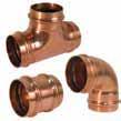
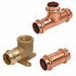
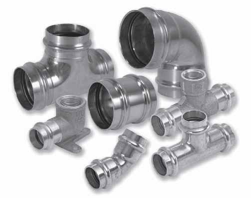
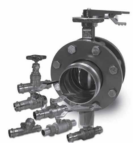
4 Quick and Easy The NIBCO Press System is user friendly, quick and easy to install. Installation can be completed in less time than traditional solder, threaded, brazed or grooved copper systems. Significant time savings means tight budgets and deadlines are met while project delays and cost overruns are avoided. Full System Product Offering The NIBCO Press System is more than just 1/2" to 4" fittings. Our offering also includes the industry's widest and most specified range of ball, gate, globe, angle, check and butterfly valves in addition to a full line of NIBCO tools necessary to complete a total system installation. Flameless The NIBCO Press System is easier and safer to use because there is no flame, solder or flux required. Connections can even be made on a wet tube! Reliable With the NIBCO Press System, a watertight joint is formed between the EPDM seal and the crimped fitting or valve providing a permanent connection. Reliability you can count on... NIBCO Press Fittings are backed by a 107-year-old company and a 50-year written guarantee. Approvals, Standards and Performance The NIBCO Press System has undergone extensive and rigorous internal and external testing and meets various worldwide, industry and governmental standards and codes, including NSF-61, CSA and UPC. All valves and fittings are manufactured under a Quality Management System conforming to the current version of ISO-9001 standards. For a complete listing of testing criteria and results or certifications and approvals please contact NIBCO Technical Services or visit. Applications The NIBCO Press System can be used in new construction or repair work and is designed for potable water, HVAC and process water systems for commercial, industrial and residential applications. Professional Appearance The NIBCO Press System creates a clean joint without the mess of excess solder or discoloration. Joint Integrity The NIBCO Press System uses engineered tools, jaws and chains that are tested and approved to ensure a consistent, reliable crimp.
5 Fittings
6 Revised 11/16/2012 ADAPTERS CAPS PC603 Adapter P x F Brass Rod (*Wrot) APPROX. DIM. A NOM. SIZE NET WT./LBS. INCHES 1/ /16 *1/2 x 3/ /32 1/2 x 3/ /32 3/ /32 3/4 x 1/ / /16 *1 x 1/ /4 1 x 3/ /16 *1 x 1 1/ /4 1 1/ /16 1 1/4 x /16 *1 1/4 x 1 1/ /32 1 1/ /16 *1 1/2 x 3/ /8 1 1/2 x 1 1/ *2 1/ /32 * /32 * /8 PC604 Adapter P x M Brass Rod (*Wrot) APPROX. DIM. B NOM. SIZE NET WT./LBS. INCHES 1/ /8 *1/2 x 3/ /32 1/2 x 3/ /4 3/ /16 3/4 x 1/ / /32 1 x 3/ /32 1 x 1 1/ /32 1 1/ /32 1 1/4 x /16 1 1/4 x 1 1/ /2 1 1/ /2 1 1/2 x 1 1/ / /16 *2 1/ /32 * /8 * /32 PC604-P Adapter PEX x P Wrot APPROX. DIM. B NOM. SIZE NET WT./LBS. INCHES 1/2 x 1/ /8 1/2 x 3/ /64 3/4 x 1/ /64 3/4 x 3/ /32 1 x /64 PC617 Cap P Wrot APPROX. DIM. N NOM. SIZE NET WT./LBS. INCHES 1/ /32 3/ / /8 1 1/ /8 1 1/ / /16 2 1/ / / /4 COUPLINGS PC600-DS Coupling P x P Wrot APPROX. DIM. A NOM. SIZE NET WT./LBS. INCHES 1/ /16 3/ / /32 1 1/ /32 1 1/ / /16 2 1/ / / /32 NOTE: Some items not certified by NSF to NSF/ANSI 61. See manufacturer's listing for approved sizes and applications, or contact NIBCO Technical Services for a complete listing of current certifications.
 Repair Coupling P x P Wrot APPROX. DIM. B NOM. SIZE NET WT./LBS. INCHES 1/2.080 1 3 /4 3/4.151 2 1 /4 1.190 2 1 /4 1 1/4.250 2 15 /32 1 1/2.511 3 11 /32 2.")
7 Revised 11/16/2012 COUPLINGS (Cont.) COUPLINGS (Cont.) ELBOWS PC600-RS Coupling P x P Wrot APPROX. DIM. A NOM. SIZE NET WT./LBS. INCHES 2 1/ / / /8 PC601 (No Stop) Repair Coupling P x P Wrot APPROX. DIM. B NOM. SIZE NET WT./LBS. INCHES 1/ /4 3/ / /4 1 1/ /32 1 1/ / /8 2 1/ / / /16 PC Elbow P x P Wrot APPROX. DIM. C DIM. D NOM. SIZE NET WT./LBS. INCHES INCHES 1/ /64 25 /64 3/ /64 31 / /8 5 /8 1 1/ /32 25 /32 1 1/ /8 7 / / /64 2 1/ /32 29 / /8 1 1 / / /16 PC600-R Reducing Coupling P x P Wrot APPROX. DIM. A NOM. SIZE NET WT./LBS. INCHES 3/4 x 1/ /32 1 x 1/ /32 1 x 3/ /16 1 1/4 x 3/ /16 1 1/4 x /2 1 1/2 x 3/ /2 1 1/2 x /32 1 1/2 x 1 1/ /14 2 x 3/ /32 2 x /16 2 x 1 1/ /16 2 x 1 1/ /16 2 1/2 x /32 2 1/2 x 1 1/ /16 2 1/2 x 1 1/ /16 2 1/2 x /16 3 x 1 1/ /32 3 x /32 3 x 2 1/ /2 4 x /4 4 x 2 1/ x /32 PC636 Crossover Coupling P x P Wrot APPROX. DIM. A NOM. SIZE NET WT./LBS. INCHES 1/ /32 3/ /4 PC Elbow Ftg x P Wrot APPROX. DIM. B DIM. C NOM. SIZE NET WT/LBS. INCHES INCHES 1/ /32 11 /32 3/ /32 9 / /32 9 /16 1 1/ /32 11 /16 1 1/ /8 7 / /8 1 3 /32 2 1/ /16 29 / / / / /2 NOTE: Some items not certified by NSF to NSF/ANSI 61. See manufacturer's listing for approved sizes and applications, or contact NIBCO Technical Services for a complete listing of current certifications.
8 Revised 11/16/2012 ELBOWS (Cont.) PC Elbow P x P Wrot APPROX. DIM. C DIM. D NOM. SIZE NET WT./LBS. INCHES INCHES 1/ / /32 3/ / /64 3/4 x 1/ / / / /16 1 1/ / /16 1 1/ / / / /16 2 1/ / / / / / /32 PC Elbow Ftg x P Wrot APPROX. DIM. B DIM. C NOM. SIZE NET WT/LBS. INCHES INCHES 1/ /32 25 /32 3/ / / / /32 1 1/ / /8 1 1/ / / / /16 2 1/ / / / / / /32 PC607-LT 90 Long Radius Elbow P x P Wrot APPROX. DIM. C DIM. D NOM. SIZE NET WT/LBS. INCHES INCHES 2 1/ / / / / /4 5 1 /4 PC607-2-LT 90 Long Radius Elbow Ftg x P - Wrot APPROX. DIM. B DIM. C NOM. SIZE NET WT/LBS. INCHES INCHES 2 1/ / / /4 4 1 /32 PC Elbow P x F - Wrot APPROX. DIM. A DIM. C NOM. SIZE NET WT/LBS. INCHES INCHES 1/ / /32 3/ / /64 1/2 x 3/ /4 25 /32 1/2 x 3/ / / / /32 PC Elbow P x F Cast APPROX. DIM. C DIM. E NOM. SIZE NET WT./LBS. INCHES INCHES 3/4 x 1/ / /64 1 1/ / /32 1 1/ / / /4 2 5 /32 PC Elbow P x M - Wrot APPROX. DIM. B DIM. C NOM. SIZE NET WT/LBS. INCHES INCHES 1/2 x 3/ /16 25 /32 3/ / /64 3/4 x 1/ / /64 1 1/ / / / /64 PC Elbow P x M Cast APPROX. DIM. C DIM. E NOM. SIZE NET WT./LBS. INCHES INCHES 1/ / / / /16 1 1/ / /2 NOTE: Some items not certified by NSF to NSF/ANSI 61. See manufacturer's listing for approved sizes and applications, or contact NIBCO Technical Services for a complete listing of current certifications.
9 Revised 11/16/2012 ELBOWS (Cont.) FLANGES MANIFOLDS PC Drop Elbow P x F Cast APPROX. DIMENSIONS NET WT. INCHES NOM. SIZE LBS. A C E 1/ /32 7 /8 27 /32 3/ / /4 31 /32 FITTING REDUCERS PC741 Companion Flange P x Flange - Bronze Flange/Wrot Outlet APPROX. DIMENSIONS NET WT. INCHES NOM. SIZE LBS. B F G W / /4 1 1/ / /8 1 1/ / / /4 3 1 /8 1 /4 3 1 /2 5 / /8 3 /8 4 3 /4 PC695 1-Outlet Manifold P x Ftg x P - Wrot APPROX. DIMENSIONS NET WT. INCHES NOM. SIZE LBS. B C F 1 x 1 x 1/ / /8 15 /16 PC600-2 Fitting Reducer Ftg x P Wrot APPROX. DIM. A NOM. SIZE NET WT/LBS. INCHES 3/4 x 1/ /8 1 x 1/ /32 1 x 3/ /32 1 1/4 x 3/ / /4 x /32 1 1/2 x 1/ /64 1 1/2 x 3/ / /2 x /16 1 1/2 x 1 1/ /4 2 x 1/ / 4 2 x 3/ / 4 2 x /32 2 X 1 1/ / 16 2 x 1 1/ /8 2 1/2 x /32 2 1/2 x 1 1/ /32 2 1/2 x 1 1/ /32 2 1/2 x /32 3 x 1 1/ /32 3 x 1 1/ /8 3 x /16 3 x 2 1/ /4 4 x /32 4 x 2 1/ /32 4 x /32 PC641 Companion Flange P x Flange - Wrot APPROX. DIMENSIONS NET WT. INCHES NOM. SIZE LBS. A B C 2 1/ / / 32 5 / / / / / / 8 27 / 32 DIMENSIONS INCHES NOM. SIZE D E F G 2 1/2 3 / / / / / 2 3 / / / 4 NOTE: 4" requires (8) "G" holes equally spaced. NOTE: Mates with ANSI Class 125/150 flanges. PC696 3-Outlet Manifold P x Ftg x P - Wrot APPROX. DIMENSIONS NET WT. INCHES NOM. SIZE LBS. B C E F 1 x 1 x 1/ /32 *See online catalog at 3 / / /8 Cont. next page NOTE: Some items not certified by NSF to NSF/ANSI 61. See manufacturer's listing for approved sizes and applications, or contact NIBCO Technical Services for a complete listing of current certifications.
10 Revised 11/16/2012 TEES PC611 Tee P x P x P Wrot APPROX. DIMENSIONS NET WT. INCHES NOM. SIZE LBS. C F G 1/ /16 11 /16 15 /32 1/2 x 1/2 x 3/ / /`16 5 /8 1/2 x 1/2 x / /32 63 /64 3/ /32 23 /32 5 /8 3/4 x 1/2 x 1/ / / /16 3/4 x 1/2 x 3/ / /16 5 /8 3/4 x 3/4 x 1/ /32 23 / /16 3/4 x 3/4 x / /32 29 / /8 7 /8 29 /32 1 x 1/2 x / /16 29 /32 1 x 3/4 x 1/ /8 1 3 / /16 1 x 3/4 x 3/ /8 1 3 / /16 1 x 3/4 x /8 1 1 /8 29 /32 1 x 1 x 1/ /8 7 /8 1 7 /32 1 x 1 x 3/ /32 27 / /16 1 x 1 x 1 1/ / /32 29 /32 1 1/ /32 1 1/4 x 1 x 3/ / /8 1 1/4 x 1 x / /64 1 1/4 x 1 1/4 x 1/ /16 1 1/4 x 1 1/4 x 3/ /8 1 1/4 x 1 1/4 x /4 1 1/ /16 15 / /32 1 1/2 x 1/2 x 1 1/ / / /2 x 3/4 x 3/ / / /16 1 1/2 x 1 x 3/ / / /16 1 1/2 x 1 x / /64 1 1/2 x 1 x 1 1/ / / /2 x 1 1/4 x / / /8 1 1/2 x 1 1/4 x 1 1/ / / /32 1 1/2 x 1 1/2 x 1/ /16 15 / /32 1 1/2 x 1 1/2 x 3/ /16 15 / /16 1 1/2 x 1 1/2 x /16 15 / /32 1 1/2 x 1 1/2 x 1 1/ /64 61 / / / / /32 2 x 1/2 x / / /32 2 x 1 x / /4 2 7 /32 2 x 1 x / / /32 2 x 1 1/4 x 1 1/ / / /8 APPROX. DIMENSIONS NET WT. INCHES NOM. SIZE LBS. C F G 2 x 1 1/2 x 3/ / / /32 2 x 1 1/2 x / / /32 2 x 1 1/2 x 1 1/ / / /16 2 x 1 1/2 x 1 1/ / / /32 2 x 2 x 1/ / / /16 2 x 2 x 3/ / / /32 2 x 2 x / / /32 2 x 2 x 1 1/ / / /32 2 x 2 x 1 1/ /8 1 1 /8 1 7 /16 2 1/ /8 1 5 /8 1 5 /8 2 1/2 x 3/4 x 2 1/ / / /8 2 1/2 x 1 x 2 1/ / / /8 2 1/2 x 1 1/4 x 2 1/ / / /8 2 1/2 x 1 1/2 x 2 1/ / /4 1 7 /8 2 1/2 x 2 x 3/ / / /32 2 1/2 x 2 x / / /32 2 1/2 x 2 x 1 1/ / /4 2 9 /16 2 1/2 x 2 x 1 1/ / /4 2 5 /8 2 1/2 x 2 x / /4 2 1 /4 2 1/2 x 2 x 2 1/ / / /8 2 1/2 x 2 1/2 x 1/ / / /16 2 1/2 x 2 1/2 x 3/ / / /16 2 1/2 x 2 1/2 x / / /16 2 1/2 x 2 1/2 x 1 1/ / / /8 2 1/2 x 2 1/2 x 1 1/ / / /8 2 1/2 x 2 1/2 x / / / /8 1 7 /8 2 1 /32 3 x 3/4 x / /4 2 3 /16 3 x 1 x / / /16 3 x 1 1/4 x / /8 2 3 /16 3 x 1 1/2 x / / /16 3 x 2 x / / /32 3 x 2 x 2 1/ / / /2 3 x 2 x / / /16 3 x 2 1/2 x / / /32 3 x 2 1/2 x 2 1/ / / /2 3 x 2 1/2 x / / /16 3 x 3 x 1/ / / /8 3 x 3 x 3/ / / /32 APPROX. DIMENSIONS NET WT. INCHES NOM. SIZE LBS. C F G 3 x 3 x / / /4 3 x 3 x 1 1/ / / /16 3 x 3 x 1 1/ / / x 3 x / / /32 3 x 3 x 2 1/ / / / / / /32 4 x 2 x /8 4 1 / /32 4 x 2 1/2 x / / /32 4 x 3 x /8 3 9 / /4 4 x 3 x 2 1/ /8 3 9 / /32 4 x 3 x /8 3 9 / /2 4 x 3 x / / /32 4 x 4 x 1/ /8 2 3 / /32 4 x 4 x 3/ /8 2 3 /8 4 1 /8 4 x 4 x /8 2 3 /8 4 5 /32 4 x 4 x 1 1/ /8 2 3 /8 4 1 /32 4 x 4 x 1 1/ /8 2 3 /8 3 3 /4 4 x 4 x /8 2 3 / /16 4 x 4 x 2 1/ /8 2 3 / /32 4 x 4 x /8 2 3 /8 3 1 /2
11 Revised 11/16/2012 TEES (Cont.) UNIONS (Cont.) ACCESSORIES PC612 Tee P x P x F Wrot APPROX. DIMENSIONS NET WT. INCHES NOM. SIZE LBS. E F G 1/ /32 11 /16 11 /16 3/4 x 3/4 x 1/ /8 23 /32 23 /32 1 x 1 x 1/ /16 7 /8 7 /8 1 x 1 x 3/ /32 27 /32 27 /32 1 1/4 x 1 1/4 x 1/ / /4 x 1 1/4 x 3/ / /2 x 1 1/2 x 1/ /64 15 /16 15 /16 1 1/2 x 1 1/2 x 3/ /8 31 /32 31 /32 2 x 2 x 1/ / / /32 2 x 2 x 3/ / / /32 2 1/2 x 2 1/2 x 3/ / / / /2 x 2 1/2 x / / / 32 3 x 3 x 3/ / 11 4 / / 16 3 x 3 x / / / 32 4 x 4 x 3/ / 11 4 / / 16 4 x 4 x / / 32 UNIONS PC733-3 Union P x F Brass Rod APPROX. DIM. A NOM. SIZE NET WT./LBS. INCHES 1 1/ /64 1 1/ /64 PC633-3 Union P x F Wrot APPROX. DIM. A NOM. SIZE NET WT./LBS. INCHES 1/ /16 3/ / / /64 EPDM Seal SIZE PART No. 1/2 T /4 T T /4 T /2 T T /2 T T T EPDM Seal (leak detection) SIZE PART No. 1/2 T /4 T T /4 T /2 T T PC633 Union P x P Wrot APPROX. DIM. A NOM. SIZE NET WT./LBS. INCHES 1/ /16 3/ / /32 1 1/ /64 1 1/ / /32 PC733-4 Union P x M Brass Rod APPROX. DIM. A NOM. SIZE NET WT./LBS. INCHES 1 1/ /64 PC633-4 Union P x M Wrot APPROX. DIM. A NOM. SIZE NET WT./LBS. INCHES 1/ /16 3/ / /32 1 1/ / /64
12 Valves


13 NIBCO Press System Illustrated Valve Index PC PC Bronze Ball Valve PC NS PC NS Bronze Ball Valve Page 13, 14 Handle Page 15, 16 PC LL PC LL Bronze Ball Valve Page 17, 18 PC HC PC HC Bronze Ball Valve Page 19, 20 PC LF PC LF Bronze Ball Valve PFFP-600 Brass Ball Valve Page 21, 22 Page 23 PF111 Bronze Gate Valve PF113 Bronze Gate Valve Page 24 Page 25 Note: Ball valves are down-rated from 600 PSI CWP to 200 PSI CWP to match the Press System.


14 Revised 12/19/2012 NIBCO Press System Illustrated Valve Index PF211-Y Bronze Globe Valve PF311-Y Bronze Angle Valve Page 26 Page 27 PF413-Y Bronze Swing Check Valve PF480-Y Bronze In-Line Check Valve Page 28 Page 29 PFD2000 Series Ductile Iron Butterfly Valve PS PS Bronze Ball Valve Operated Page 30 Page 31, 32 PS HC Bronze Ball Valve PF221/222-A/B Bronze Y-Strainer Page 33 or solid cap SS Perforated Screen Page 34 Note: Ball valves are down-rated from 600 PSI CWP to 200 PSI CWP to match the Press System. Note: Check valves are down-rated from 250 PSI CWP to 200 PSI CWP to match the Press System.
15 NIBCO Press System Bronze Ball Valves Dezincification Resistant 250 PSI/17.2 Bar Non-Shock Cold Working Pressure 250 F Maximum Operating Temperature CONFORMS TO MSS SP-110 MATERIAL LIST SPECIFICATION PART 1. Body Bronze ASTM B584 Alloy C Body End Bronze ASTM B584 Alloy C Press End Adapter (2) Bronze ASTM B61 Alloy C Ball Brass ASTM B16 Alloy C36000 or ASTM B283 Alloy C37700 (Chrome/Nickel Plated) 5. Seat Ring (2) Reinforced PTFE 6. Boss seal o-ring (2) EPDM 7. O-Ring (2) EPDM 8. Packing PTFE 9. Pack Gland Brass ASTM B16 Alloy C Stem Silicon Bronze ASTM B371 Alloy C69430 or ASTM B371 Alloy C Handle Nut Zinc Plated Steel 12. Thrust Washer Reinforced PTFE 13. Handle Assembly Zinc Plated Steel with Plastisol Coating PC Press x Press Female End DIMENSIONS WEIGHTS Dimensions SIZE A B C D E Weight In. mm. In. mm. In. mm. In. mm. In. mm. In. mm. Lbs. Kg. ¼ ½ NIBCO Press System ball valves are designed to meet MSS SP-110 with the exception of the end connection. Ball valves are down-rated from 600 PSI CWP to 250 PSI CWP to match the Press System. Male and female press-to-connect ends are new technology not yet covered in the current edition of this specification. PC P x P
16 NIBCO Press System Bronze Ball Valves Dezincification Resistant 250 PSI/17.2 Bar Non-Shock Cold Working Pressure 250 F Maximum Operating Temperature CONFORMS TO MSS SP-110 MATERIAL LIST SPECIFICATION PART 1. Body Bronze ASTM B584 Alloy C Body End Bronze ASTM B584 Alloy C Female Adapter (2) Bronze ASTM B61 Alloy C Ball (vented) Stainless Steel ASTM A276 Type 316 or ASTM A351 Type CF8M 5. Seat Ring (2) Reinforced PTFE 6. Boss Seal O-Ring (2) EPDM 7. O-Ring (2) EPDM 8. Packing PTFE 9. Pack Gland Brass ASTM B16 Alloy C Stem Stainless Steel ASTM A276 Type Handle Nut 300 Series Stainless Steel 12. Thrust Washer Reinforced PTFE 13. Handle Assembly Zinc Plated Steel with Plastisol Coating PC Press x Press Female End DIMENSIONS WEIGHTS Dimensions SIZE A B C D E Weight In. mm. In. mm. In. mm. In. mm. In. mm. In. mm. Lbs. Kg ¼ ½ NIBCO Press System ball valves are designed to meet MSS SP-110 with the exception of the end connection. Ball valves are down-rated from 600 PSI CWP to 250 PSI CWP to match the Press System. Male and female press-to-connect ends are new technology not yet covered in the current edition of this specification. PC P x P
17 NIBCO Press System Bronze Ball Valves EAL Handle Dezincification Resistant 250 PSI/17.2 Bar Non-Shock Cold Working Pressure CONFORMS TO MSS SP-110 MATERIAL LIST PART SPECIFICATION 1. Body Bronze ASTM B584 Alloy C Body End Bronze ASTM B584 Alloy C Female Adapter (2) Bronze ASTM B61 Alloy C Ball Brass ASTM B16 Alloy C36000 or ASTM B283 Alloy C37700 (Chrome/Nickel Plated) 5. Seat Ring (2) Reinforced PTFE 6. Boss Seal O-Ring (2) EPDM 7. O-Ring (2) EPDM 8. Packing PTFE 9. Thread Pack Gland Brass ASTM B16 Alloy C Stem Silicon Bronze ASTM B371 Alloy C69300 or ASTM B371 Alloy C Handle Nut Zinc Plated Steel 12. Thrust Washer Reinforced PTFE 13. NIB-SealHandle Assembly Zinc Plated Steel & Plastic PC NS Press x Press Female End DIMENSIONS WEIGHTS Dimensions SIZE A B C D E Weight In. mm. In. mm. In. mm. In. mm. In. mm. In. mm. Lbs. Kg. ¼ ½ NIBCO Press System ball valves are designed to meet MSS SP-110 with the exception of the end connection. Ball valves are down-rated from 600 PSI CWP to 250 PSI CWP to match the Press System. Male and female press-to-connect ends are new technology not yet covered in the current edition of this specification. PC NS P x P
18 NIBCO Press System Bronze Ball Valves EAL Dezincification Resistant 250 PSI/17.2 Bar Non-Shock Cold Working Pressure CONFORMS TO MSS SP-110 CONFORMS TO MSS SP-110 MATERIAL LIST PART SPECIFICATION 1. Body Bronze ASTM B584 Alloy C Body End Bronze ASTM B584 Alloy C Female Adapter (2) Bronze ASTM B61 Alloy C Ball (vented) ASTM A276 Type 316 Stainless Steel or ASTM A351 Type CF8M 5. Seat Ring (2) Reinforced PTFE 6. Boss Seal O-Ring (2) EPDM 7. O-Ring (2) EPDM 8. Packing PTFE 9. Pack Gland Brass ASTM B16 Alloy C Stem ASTM A276 Alloy Type 316 Stainless Steel 11. Handle Nut 300 Series Stainless Steel 12. Thrust Washer Reinforced PTFE 13. NIB-SealHandle Assembly Zinc Plated Steel & Plastic PC NS Press x Press Female End DIMENSIONS WEIGHTS Dimensions SIZE A B C D E Weight In. mm. In. mm. In. mm. In. mm. In. mm. In. mm. Lbs. Kg. ¼ ½ NIBCO Press System ball valves are designed to meet MSS SP-110 with the exception of the end connection. Ball valves are down-rated from 600 PSI CWP to 250 PSI CWP to match the Press System. Male and female press-to-connect ends are new technology not yet covered in the current edition of this specification. PC NS P x P
19 NIBCO Press System Bronze Ball Valves Dezincification Resistant 250 PSI/17.2 Bar Non-Shock Cold Working Pressure 250 F Maximum Operating Temperature CONFORMS TO MSS SP-110 MATERIAL LIST SPECIFICATION PART 1. Body Bronze ASTM B584 Alloy C Body End Bronze ASTM B584 Alloy C Female Adapter (2) Bronze ASTM B61 Alloy C Ball Brass ASTM B16 Alloy C36000 or ASTM B283 C37700 (Chrome/Nickel Plated) 5. Seat Ring (2) Reinforced PTFE 6. Boss Seal O-Ring (2) EPDM 7. O-Ring (2) EPDM 8. Packing PTFE 9. Pack Gland Brass ASTM B16 Alloy C Stem Silicon Bronze ASTM B371 Alloy C69300 or ASTM B371 Alloy C Handle Nut Zinc Plated Steel 12. Thrust Washer Reinforced PTFE 13. Locking Handle Zinc Plated Steel with Plastisol Coating 14. Locking Device 300 Series Stainless Steel PC LL Press x Press Female End DIMENSIONS WEIGHTS Dimensions SIZE A B C D E Weight In. mm. In. mm. In. mm. In. mm. In. mm. In. mm. Lbs. Kg. ¼ ½ NIBCO Press System ball valves are designed to meet MSS SP-110 with the exception of the end connection. Ball valves are down-rated from 600 PSI CWP to 250 PSI CWP to match the Press System. Male and female press-to-connect ends are new technology not yet covered in the current edition of this specification. PC LL P x P
20 NIBCO Press System Bronze Ball Valves Dezincification Resistant 250 PSI/17.2 Bar Non-Shock Cold Working Pressure 250 F Maximum Operating Temperature CONFORMS TO MSS SP-110 MATERIAL LIST SPECIFICATION PART 1. Body Bronze ASTM B584 Alloy C Body End Bronze ASTM B584 Alloy C Female Adapter (2) Bronze ASTM B61 Alloy C Ball (vented) Stainless Steel ASTM A276 Type 316 or ASTM A351 Type CF8M 5. Seat Ring (2) Reinforced PTFE 6. Boss Seal O-Ring (2) EPDM 7. O-Ring (2) EPDM 8. Packing PTFE 9. Pack Gland Brass ASTM B16 Alloy C Stem Stainless Steel ASTM A276 Type Handle Nut 300 Series Stainless Steel 12. Thrust Washer Reinforced PTFE 13. Locking Handle Assembly Zinc Plated Steel with Plastisol Coating 14. Locking Device 300 Series Stainless Steel PC LL Press x Press Female End DIMENSIONS WEIGHTS Dimensions SIZE A B C D E Weight In. mm. In. mm. In. mm. In. mm. In. mm. In. mm. Lbs. Kg. ¼ ½ NIBCO Press System ball valves are designed to meet MSS SP-110 with the exception of the end connection. Ball valves are down-rated from 600 PSI CWP to 250 PSI CWP to match the Press System. Male and female press-to-connect ends are new technology not yet covered in the current edition of this specification. PC LL P x P
21 NIBCO Press System Bronze Ball Valves 250 PSI/17.2 Bar Non-Shock Cold Working Pressure 250 F Maximum Operating Temperature CONFORMS TO MSS SP-110 MATERIAL LIST SPECIFICATION PART 1. Press End Adapter Bronze ASTM B61 Alloy C Body Bronze ASTM B584 Alloy C Hose Body End Brass ASTM B124 Alloy C Cap Die Cast Brass 5. O-Ring EPDM 6. Boss seal o-ring EPDM 7. Ball Brass ASTM B16 Alloy C36000 or ASTM B283 Alloy C37700 (Chrome/Nickel Plated) 8. Packing PTFE 9. Pack Gland Brass ASTM B16 Alloy C Stem Silicon Bronze ASTM B371 Alloy C69300 or ASTM B371 Alloy C Handle Nut Zinc Plated Steel 12. Thrust Washer Reinforced PTFE 13. Handle Assembly Zinc Plated Steel with Plastisol Coating 14. Seat Ring (2) Reinforced PTFE PC HC Press Female x Hose End DIMENSIONS WEIGHTS Dimensions SIZE A B C D Weight In. mm. In. mm. In. mm. In. mm. In. mm. Lbs. Kg. NIBCO Press System ball valves are designed to meet MSS SP-110 with the exception of the end connection. Ball valves are down-rated from 600 PSI CWP to 250 PSI CWP to match the Press System. Male and female press-to-connect ends are new technology not yet covered in the current edition of this specification. PC HC P x Hose
22 NIBCO Press System Bronze Ball Valves 250 PSI/17.2 Bar Non-Shock Cold Working Pressure 250 F Maximum Operating Temperature CONFORMS TO MSS SP-110 MATERIAL LIST SPECIFICATION PART 1. Female Adapter Bronze ASTM B61 Alloy C Body Bronze ASTM B584 Alloy C Hose Body End Brass ASTM B124 Alloy C Cap Die Cast Brass 5. O-Ring EPDM 6. Boss seal o-ring EPDM 7. Ball (vented) Stainless Steel ASTM A276 Type 316 or ASTM A351 Type CF8M 8. Packing PTFE 9. Pack Gland Brass ASTM B16 Alloy C Stem Stainless Steel ASTM A276 Type Handle Nut 300 Series Stainless Steel 12. Thrust Washer Reinforced PTFE 13. Handle Assembly Zinc Plated Steel with Plastisol Coating 14. Seat Ring (2) Reinforced PTFE PC HC Press Female x Hose End DIMENSIONS WEIGHTS Dimensions SIZE A B C D Weight In. mm. In. mm. In. mm. In. mm. In. mm. Lbs. Kg. NIBCO Press System ball valves are designed to meet MSS SP-110 with the exception of the end connection. Ball valves are down-rated from 250 PSI CWP to 250 PSI CWP to match the Press System. Male and female press-to-connect ends are new technology not yet covered in the current edition of this specification. PC HC P x Hose
23 Revised 12/19/2012 NIBCO Press System Lead-Free * Bronze Ball Valves Size Range: 1/2-2 Pressure Rating: 250 PSI CWP Body Design Pressure: 600 PSI CWP Maximum Operating Temperature: 250 F Dezincification Resistant MATERIAL LIST SPECIFICATION PART 1. Handle Nut Plated Steel 2. Stem Silicon Bronze ASTM B371 Alloy C Pack Gland Brass ASTM B16 Alloy C Packing, Stem PTFE 5. Thrust Washer Reinforced PTFE 6. Handle Assembly Plated Steel with Plastisol Coating 7. Body End Silicon Bronze ASTM B584 Alloy C Seat Ring (2) Reinforced PTFE 9. Ball Silicon Bronze ASTM B283 Alloy C Body Silicon Bronze ASTM B584 Alloy C Boss seal o-ring (2) EPDM 12. O-Ring (2) EPDM 13. Press End Adapter (2) Wrot Copper ASTM B75 Alloy C12200 PC LF Press x Press Female End Handle Markings DIMENSIONS WEIGHTS Dimensions SIZE A B C D E Weight In. mm. In. mm. In. mm. In. mm. In. mm. In. mm. Lbs. Kg. ¼ ½ NIBCO Press System ball valves are designed to meet MSS SP-110 with the exception of the end connection. Ball valves are down-rated from 600 PSI CWP to 250 PSI CWP to match the Press System. PC LF P x P Handle Options:

24 Revised 12/19/2012 NIBCO Press System Lead-Free * Bronze Ball Valves Size Range: 1/2-2 Pressure Rating: 250 PSI CWP Body Design Pressure: 600 PSI CWP Maximum Operating Temperature: 250 F Dezincification Resistant MATERIAL LIST SPECIFICATION PART 1. Handle Nut Plated Steel 2. Stem Stainless Steel ASTM A276 Type Pack Gland Brass ASTM B16 Alloy C Packing, Stem PTFE 5. Thrust Washer Reinforced PTFE 6. Handle Assembly Plated Steel with Plastisol Coating 7. Body End Silicon Bronze ASTM B584 Alloy C Seat Ring (2) Reinforced PTFE 9. Ball (vented) Stainless Steel ASTM A276 Type Body Silicon Bronze ASTM B584 Alloy C Boss seal o-ring (2) EPDM 12. O-Ring (2) EPDM 13. Press End Adapter (2) Wrot Copper ASTM B75 Alloy C12200 PC LF Press x Press Female End Handle Markings DIMENSIONS WEIGHTS Dimensions SIZE A B C D E Weight In. mm. In. mm. In. mm. In. mm. In. mm. In. mm. Lbs. Kg. ¼ ½ NIBCO Press System ball valves are designed to meet MSS SP-110 with the exception of the end connection. Ball valves are down-rated from 600 PSI CWP to 250 PSI CWP to match the Press System. PC LF P x P Handle Options:
25 NIBCO Press System Brass Ball Valves 200 PSI/41.4 Bar Non-Shock Cold Working Pressure 250 F Maximum Operating Temperature CONFORMS TO MSS SP-110 MATERIAL LIST SPECIFICATION PART 1. Handle Plated Steel with Plastisol Cover 2. Handle Nut Plated Steel 3. Pack Gland Brass ASTM B16 Alloy C Packing, Stem Virgin PTFE 5. Flat Washer 430 Stainless 6. O-Ring (Stem Seal) Fluorocarbon (FKM) 7. Thrust Washer Reinforced PTFE 8. Stem 1 /2" - 1" Brass ASTM B16 Alloy C /4" - 2" Silicon Bronze ASTM B371 Alloy or Body Forged Brass ASTM B283 Alloy C Seat Ring (2) Virgin PTFE 11. Ball 1 /2" - 3 /4" Brass ASTM B16 Alloy C36000 (Chrome/Nickel Plated) 1" - 2" Forged Brass ASTM B124 Alloy C37700 (Chrome/Nickel Plated) 12. Body End Piece Forged Brass ASTM B283 Alloy C Female Adapter (2) Bronze ASTM B61 Alloy C O-Ring (2) EPDM PFFP600 Press x Press Female End DIMENSIONS WEIGHTS Dimensions Size A B C D Weight In. mm. In. mm. In. mm. In. mm. In. mm. Lbs. Kg. ¹ ₂ ³ ₄ ¹ ₄ ¹ ₂ NIBCO Press System ball valves are designed to meet MSS SP-110 with the exception of the end connection. Ball valves are down-rated from 600 PSI CWP to 200 PSI CWP to match the Press System. Male and female press-to-connect ends are new technology not yet covered in the current edition of this specification. PFFP600 P x P
26 NIBCO Press System Bronze Gate Valves Dezincification Resistant CONFORMS TO MSS SP-80 MATERIAL LIST SPECIFICATION PART 1. Handwheel Nut 300 Series Stainless Steel 2. Identification Plate Aluminum 3. Handwheel Malleable Iron ASTM A Stem Silicon Bronze ASTM B 371 Alloy C69430 or ASTM B 99 Alloy C Pack Nut Brass ASTM B 16 Alloy C Pack Gland Brass ASTM B 16 Alloy C Packing Aramid Fibers with Graphite 8. Bonnet Bronze ASTM B 62 Alloy C Body Assembly Bronze ASTM B 62 Alloy C Wedge Bronze ASTM B 62 Alloy C Female Adapter (2) Bronze ASTM B 61 Alloy C O-Ring (2) EPDM PF111 Press x Press Female End DIMENSIONS WEIGHTS Dimensions Size A B C Weight In. mm. In. mm. In. mm. In. mm. Lbs. Kg. ¹ ₂ ³ ₄ ¹ ₄ ¹ ₂ NIBCO Press System gate valves are designed to meet MSS SP-80 with the exception of the end connection. Male and female press-to-connect ends are new technology not yet covered in the current edition of this specification. PF111 P x P
27 NIBCO Press System Bronze Gate Valves Dezincification Resistant CONFORMS TO MSS SP-80 MATERIAL LIST PART SPECIFICATION 1. Handwheel Nut 300 Series Stainless Steel 2. Identification Plate Aluminum 3. Handwheel Malleable Iron ASTM A Stem Silicon Bronze ASTM B 371 Alloy C69430 or ASTM B 99 Alloy C Pack Nut Brass ASTM B 16 Alloy C Pack Gland Brass ASTM B 16 Alloy C Packing Aramid Fibers with Graphite 8. Stuffing Box Bronze ASTM B 62 Alloy C Bonnet Bronze ASTM B 62 Alloy C Body Assembly Bronze ASTM B 62 Alloy C Wedge Bronze ASTM B 62 Alloy C Female Adapter (2) Bronze ASTM B 61 Alloy C O-Ring (2) EPDM PF113 Press x Press Female End DIMENSIONS WEIGHTS Dimensions Size A B C Weight In. mm. In. mm. In. mm. In. mm. Lbs. Kg. ¹ ₂ ³ ₄ ¹ ₄ ¹ ₂ PF113 P x P NIBCO Press System gate valves are designed to meet MSS SP-80 with the exception of the end connection. Male and female press-to-connect ends are new technology not yet covered in the current edition of this specification.

28 NIBCO Press System Bronze Globe Valves Dezincification Resistant CONFORMS TO MSS SP-80 MATERIAL LIST PART SPECIFICATION 1. Handwheel Nut 300 Series Stainless Steel 2. Identification Plate Aluminum 3. Handwheel Malleable Iron ASTM A Stem Silicon Bronze ASTM B 371 Alloy C Pack Gland Brass ASTM B 16 Alloy C Pack Nut Brass ASTM B 16 Alloy C Packing Aramid Fibers with Graphite 8. Bonnet Bronze ASTM B 62 Alloy C Disc Holder Nut Bronze ASTM B 62 Alloy C Disc Holder Bronze ASTM B 62 Alloy C Disc PTFE 12. Disc Washer 304 Stainless Steel 13. Disc Nut Bronze ASTM B 98 Alloy C Body Assembly Bronze ASTM B62 Alloy C Female Adapter (2) Bronze ASTM B 61 Alloy C O-Ring (2) EPDM PF211-Y Press x Press Female End DIMENSIONS WEIGHTS Dimensions Size A B C Weight In. mm. In. mm. In. mm. In. mm. Lbs. Kg. *¹ ₂ ³ ₄ ¹ ₄ ¹ ₂ NIBCO Press System globe valves are designed to meet MSS SP-80 with the exception of the end connection. Male and female press-to-connect ends are new technology not yet covered in the current edition of this specification. PF211-Y P x P

29 NIBCO Press System Bronze Angle Valves Dezincification Resistant CONFORMS TO MSS SP-80 MATERIAL LIST PART SPECIFICATION 1. Handwheel Nut 300 Series Stainless Steel 2. Identification Plate Aluminum 3. Handwheel Malleable Iron ASTM A Stem Silicon Bronze ASTM B 371 Alloy C Pack Gland Brass ASTM B 16 Alloy C Pack Nut Brass ASTM B 16 Alloy C Packing Aramid Fibers with Graphite 8. Bonnet Bronze ASTM B 62 Alloy C Disc Holder Nut Bronze ASTM B 62 Alloy C Disc Holder Bronze ASTM B 62 Alloy C Disc PTFE 12. Disc Washer 304 Stainless Steel 13. Disc Nut Silicon Bronze ASTM B 96 Alloy C Body Bronze ASTM B 62 Alloy C Female Adapter (2) Bronze ASTM B 61 Alloy C O-Ring (2) EPDM PF311-Y Press x Press Female End Dimensions Size B H J Weight In. mm. In. mm. In. mm. In. mm. Lbs. Kg. *¹ ₂ ³ ₄ ¹ ₄ ¹ ₂ NIBCO Press System angle valves are designed to meet MSS SP-80 with the exception of the end connection. Male and female press-to-connect ends are new technology not yet covered in the current edition of this specification. PF311-Y P x P

30 NIBCO Press System Bronze Check Valves Dezincification Resistant CONFORMS TO MSS SP-80 MATERIAL LIST PART SPECIFICATION 1. Bonnet Bronze ASTM B 62 Alloy C Body Bronze ASTM B 62 Alloy C Hinge Pin Bronze ASTM B 140 Alloy C Disc Hanger Bronze ASTM B 62 Alloy C83600 or 304 SS 1/2" and 3/4" sizes only 5. Hanger Nut Brass ASTM B 16 Alloy C Disc Holder Bronze ASTM B 62 Alloy C Seat Disc PTFE 8. Seat Disc Nut Brass ASTM B 16 Alloy C Hinge Pin Plug Bronze ASTM B 140 Alloy C32000 (not shown) *10. Seat Disc Washer ASTM B 98 Alloy C65500 or ASTM B Female Adapter (2) Bronze ASTM B 61 Alloy C O-Ring (2) EPDM PF413-Y Press x Press Female End * Sizes 3/4" thru 2" only. DIMENSIONS WEIGHTS Dimensions Size A B Weight In. mm. In. mm. In. mm. Lbs. Kg. ¹ ₂ ³ ₄ ¹ ₄ ¹ ₂ PF413-Y P x P NIBCO Press System check valves are designed to meet MSS SP-80 with the exception of the end connection. Male and female press-to-connect ends are new technology not yet covered in the current edition of this specification. WARNING Do not use for Reciprocating Air Compressor Service NIBCO check valves may be installed in both horizontal and vertical lines with upward flow or in any intermediate position. They will operate satisfactorily in a declining plane (no more than 15º).

31 NIBCO Press System Bronze In-line Lift Check Valves 200 PSI/17.2 Bar Non-Shock Cold Working Pressure 250 F Maximum Operating Temperature Dezincification Resistant MATERIAL LIST PART SPECIFICATION 1. Body Bronze ASTM B584 Alloy C Stem Stainless Steel ASTM A582 Alloy C Spring 316 Stainless Steel 4. Disc Holder Stainless Steel Type Disc PTFE 6. Seat Screw Stainless Steel ASTM A276 Alloy S Body End Bronze ASTM B584 Alloy C Adapter (2) Bronze ASTM B61 Alloy C O-Ring (2) EPDM PF480-Y Press x Press Female End DIMENSIONS WEIGHTS Dimensions Size A B C Weight In. mm. In. mm. In. mm. In. mm Lbs. Kg. ¹ ₂ ³ ₄ ¹ ₄ ¹ ₂ PF480-Y (PTFE Disc) P x P NIBCO Press System check valves may be installed in both horizontal and vertical lines with upward flow or in any intermediate position. WARNING - Do Not Use for reciprocating air compressor service. NOTE: 0.5 PSI pressure required to open spring. NOTE: Check valves are down-rated from 250 PSI CWP to 200 PSI CWP to match the Press System.

32 NIBCO Press System Butterfly Valves Sizes 2 1/2" through 4" MATERIAL LIST PART SPECIFICATION 1. Stem Stainless Steel ASTM A 582 Type Collar Bushing Brass ASTM B Stem Seal EPDM Rubber 4. Body Seal EPDM Rubber 5. Nameplate Aluminum 6. Upper Bushing Wrot Copper ASTM B 75 Alloy C Liner EPDM Rubber 8. Disc Alum. Brz. ASTM B 148 Alloy 954/ Lower Bushing Wrot Copper ASTM B 75 Alloy C Body Lug Ductile Iron ASTM A Flange Body (2) Carbon Steel 12. Flange Gasket (2) EPDM 13. Flange Press Ends (2) Wrot Copper ASTM B 75 Alloy C O-Ring (2) EPDM 15. Cap Screws Carbon Steel PFD2000 Lug Style EPDM Liner and Aluminum Bronze Disc Press x Press Female End Available with lock lever handle or gear operator. DIMENSIONS WEIGHTS Size G Metal Rubber In. mm. A B C D E F Flat H I Total Size J N O P R S Lug Weight In. mm. Square Dia. B.C. Dia. Dia. No. Length Lbs. Kg Refer to page for bolt lengths NIBCO Press System butterfly valves are designed to meet MSS SP-67 with the exception of the end connection. Male and female press-to-connect ends are new technology not yet covered in the current edition of this specification. NOT RECOMMENDED FOR STEAM SERVICE
33 NIBCO Press System Bronze Ball Valves Dezincification Resistant CONFORMS TO MSS SP-110 MATERIAL LIST SPECIFICATION PART 1. Handle Nut Zinc Plated Steel 2. Handle Assembly Zinc Plated Steel with Plastisol Cover 3. Pack Gland Brass ASTM B 16 Alloy C Packing PTFE 5. Stem Silicon Bronze ASTM B 371 Alloy C Thrust Washer RPTFE 7. Ball Brass ASTM B 16 Alloy C36000 or ASTM B 124 Alloy C37700 (Chrome/Nickle Plated) 8. Seat Ring (2) RPTFE 9. Body Bronze ASTM B 584 Alloy C Body End Piece Bronze ASTM B 584 Alloy C Stub Out (2) Type L Copper Tube PS Press x Press Male End DIMENSIONS WEIGHTS Dimensions Size A B C D Weight In. mm. In. mm. In. mm. In. mm. In. mm. Lbs. Kg. ¹ ₂ ³ ₄ ¹ ₄ ¹ ₂ PS P x P NIBCO Press System ball valves are designed to meet MSS SP-110 with the exception of the end connection. Ball valves are down-rated from 600 PSI CWP to 200 PSI CWP to match the Press System. Male and female press-to-connect ends are new technology not yet covered in the current edition of this specification.
34 NIBCO Press System Bronze Ball Valves Dezincification Resistant Nominal sizes 1/2" through 1" are UL certified to NSF/ANSI 61 CONFORMS TO MSS SP-110 MATERIAL LIST SPECIFICATION PART 1. Handle Nut Zinc Plated Steel 2. Handle Assembly Zinc Plated Steel with Plastisol Cover 3. Pack Gland Brass ASTM B 16 Alloy C Packing PTFE 5. Stem ASTM A 276 Alloy S31600 Stainless Steel 6. Thrust Washer RPTFE 7. Ball ASTM A 276 Alloy S31600 Stainless Steel 8. Seat Ring (2) RPTFE 9. Body Bronze ASTM B 584 Alloy C Body End Piece Bronze ASTM B 584 Alloy C Stub Out (2) Type L Copper Tube PS Press x Press Male End DIMENSIONS WEIGHTS Dimensions PS P x P Size A B C D Weight In. mm. In. mm. In. mm. In. mm. In. mm. Lbs. Kg. ¹ ₂ ³ ₄ ¹ ₄ ¹ ₂ NIBCO Press System ball valves are designed to meet MSS SP-110 with the exception of the end connection. Ball valves are down-rated from 600 PSI CWP to 200 PSI CWP to match the Press System. Male and female press-to-connect ends are new technology not yet covered in the current edition of this specification.

35 NIBCO Press System Bronze Ball Valves ³ ₄" Hose Connection CONFORMS TO MSS SP-110 MATERIAL LIST SPECIFICATION PART 1. Handle Nut Zinc Plated Steel 2. Handle Zinc Plated Steel 3. Pack Gland Brass ASTM B 16 Alloy C Packing PTFE 5. Thrust Washer RPTFE 6. Stem Silicon Bronze ASTM B 371 Alloy C Ball Brass ASTM B 16 Alloy C36000 or ASTM B 124 Alloy C37700 (Chrome/Nickle Plated) 8. Seat Rings Reinforced PTFE 9. Body Assembly Bronze ASTM B 584 Alloy C Hose Body End Brass ASTM B 124 Alloy C Cap Die Cast Brass 12. Gasket Rubber 13. Chain Brass 14. Stub Out Type L Copper Tube PS HC Press Male x Hose End DIMENSIONS WEIGHTS Dimensions Size A B C Weight In. mm. In. mm. In. mm. In. mm. Lbs. Kg. ¹ ₂ ³ ₄ PS HC Press x Hose NIBCO Press System ball valves are designed to meet MSS SP-110 with the exception of the end connection. Ball valves are down-rated from 600 PSI CWP to 200 PSI CWP to match the Press System. Male and female press-to-connect ends are new technology not yet covered in the current edition of this specification.

 EPDM PF221/222-A Press x Press Female End END CONNECTION SCREEN CAP PF- Female Press 221-20 Mesh (STD.) A - Tapped Cap w/plug (STD.")
36 Class 125 Bronze Y-Strainers 200 PSI/13.8 Bar Non-Shock Cold Working Pressure 250 F Maximum Operating Temperature CONFORMS TO MSS SP-110 PART MATERIAL LIST SPECIFICATION 1. Body Bronze ASTM B584 Alloy C Cap Bronze ASTM B62 Alloy C Gasket PTFE 4. Screen ASTM E Mesh Stainless Steel or ASTM E674 Perforated Stainless Steel 5. Plug Brass ASTM B16 Alloy C36000 or Bronze ASTM B584 Alloy C Female Adapter (2) Bronze ASTM B61 Alloy C O-Ring (2) EPDM PF221/222-A Press x Press Female End END CONNECTION SCREEN CAP PF- Female Press Mesh (STD.) A - Tapped Cap w/plug (STD.) PF - Female Press Perforated B - Solid Cap PF221/222-A P x P DIMENSIONS WEIGHTS QUANTITIES Dimensions Size A C D Weight In. mm. In. mm. In. mm. Threads Lbs. Kg. ¹ ₂ /4 NPT ³ ₄ /8 NPT /8 NPT ¹ ₄ /4 NPT ¹ ₂ /4 NPT NPT PF221/222-B Press x Press Female End PF221/222-B P x P

37 NIBCO Press System Ball Valve Handle Options A wide variety of handles are available to fulfill safety and operation requirements in various processing and manufacturing industries. The lever handle with plastic cover is standard. Other handle options are shown. Stainless steel lever handles are available, as an option, also with plastic covers. If an optional handle is desired, please indicate which one when ordering. Many of these options are field assembly only. CS Standard Lever Handle CS Extended Lever Handle with Memory Stop NIB-SEAL Handle CS Locking Lever Handle CS Round Handle Vertical Chain Lever SS Standard Lever Handle CS Extended Round Handle Horizontal Chain Lever SS Locking Lever Handle CS Wing Handle Memory Stop Kit CS Extended Lever Handle

38 NIBCO Press System Bronze Ball Valves NIB-SEAL Technical Data NIBCO bronze ball valves installed with NIB-SEAL insulated handles are the only approach that keeps your insulated piping system completely intact. The revolutionary NIB-SEAL bronze ball valve stops condensate cold. Its unique thermal barrier design keeps moisture from infiltrating your insulated system while preventing thermal energy loss through exposed metal handles. Designed for new installations or retrofitting existing systems, NIB-SEAL bronze ball valves offer a wide range of advantages for typical commercial HVAC systems as well as industrial applications where insulated piping is desirable. valve without destroying the integrity of the insulated system. balancing. The valve packing is also readily accessible for routine maintenance. piping system. Cap keeps moisture-laden air out to reduce chance of condensate formation Insulation plug provides vapor seal, keeping air from infiltrating the insulated system Handle nut Indicator gives at-a-glance valve position Memory stop plate and screws for system balancing Pre-formed hole for identification tag Extension handle of durable non-thermal conductive material prevents formation of condensation Protective sleeve allows operation of valve handle and maintenance of valve packing while maintaining integrity of piping insulation Temperature range: 15 F to 250 F NIBCO Press System bronze ball valve is an integral part of the NIB-SEAL valve system US PATENT 5,236,006


39 Butterfly Valve Options and Accessories Lever-Lock Operator (Standard) PFD2000 Position-Lock Operator (Optional) PFD2000 The lever-lock handle and throttling plate provide throttling notches every 10 o for excellent manual control in balancing up to 90 o or shut off service. The valve may be padlocked in any one of the positions including opened or closed by virtue of a locking hole located in the handle and lever. MATERIAL LIST PART SPECIFICATION 1. Handle Polymer Coated Iron 2. Lever-Lock Zinc Plated Steel 3. Throttle Plate Zinc Plated Steel DIMENSIONS AND TORQUE OUTPUT The position-lock can be used to set the valve in any position or as a memory stop so the valve may be reopened to the previous position. The valve may be padlocked in full open or full closed position. Ordering: Sold as a field retrofitable kit only. PFD Dimensions Torque Rated Output in Inch-Pounds Lever Throttle Plate Throttle Plate/ Size (STD) (STD) Infinite Pos. Kit A B C D At 60 pounds Pull At 100 pounds Pull 2¹ ₂ -3 T115107PP T115138PP T114841FG 10¹ ₂ 1 4⁵ ₈ 6³ ₁₆ 540 In-Lbs. 900 In-Lbs. 4 T115108PP T115138PP T114842FG 10¹ ₂ 1 4⁵ ₈ 6³ ₁₆ 540 In-Lbs. 900 In-Lbs. Gear Operator options and accessories (2 1/2" through 4" 2000 series only) 2" Square Operating Nut Memory Stop Flag Indicator Consult factory for: Square Operating Nut, Memory Stop and Flag Indicator 2 1/2"-4" Cast Iron Gear Operator The NIBCO butterfly valve can be provided with heavy-duty operator and indicator. Recommended for valves 8" and larger, for trouble-free operation in all moisture and weather conditions (not submersible). Operator is a self-locking worm gear type. Equipped with adjustable stops at open and shut positions. Ordering: Specify by adding (-5) to Fig. No., i.e., PFD Babbit Sprocket may be added to handwheel. See below for sizing information. Available options: Memory Stop Gear Operator Kit, 2" Square Operating Nut, Flag Indicator and Handwheel for GO. PFD VALVE 2½ GEAR OPERATOR DETAIL FOR SIZES 2 1/2" TO 4" (PFD2000 ONLY) GEAR OPERATOR ACCESSORIES & REPLACEMENT PARTS GEAR GEAR STEM SPROCKET SQUARE OPERATOR RATIO OP DIMENSIONS (INCHES) ADAPTER RIM OPERATING FLAG MEMORY REPLACEMENT NUMBER WEIGHT A B C D E F BUSHING MODEL NUT INDICATOR STOP KIT HANDWHEEL T117118PP 24: T046653PP #1½ T117792FC T116682PP T026196PP T117122PP T117118PP 24: T046654PP #1½ T117792FC T116682PP T026196PP T117122PP Notes - 1. Stem adapter bushing must be ordered seperately when needed for smaller size valves. 2. All other accessories must be ordered separately. (Sprocket rim, square operator nut, flag indicator & memory stop kit.) 3. Gear operator comes with handwheel.
40 Butterfly Valve Technical Information Valve Installation Procedure Always position the connecting pipe flanges accurately in the line, allowing sufficient space between the flanges for the valve. Make sure the pipe flange faces are clean of any foreign material such as scale, metal shavings or welding slag. Valves should be installed with the disc in the closed position to prevent damage to sealing surfaces. 1. Carefully insert the valves between the pipe flanges. Do not apply any lubricants to the seat faces as this may damage them. 2. Line up, center and secure the valve between flanges using desired bolts or studs as listed in Table 4. Do not tighten bolts at this time. 3. Carefully open the valve to assure free unobstructed disc movement. Disc interference may result when valves are installed in pipelines having smaller than normal inside diameters, such as heavy wall pipe, plastic-lined pipe, as-cast flanges or reducing flanges. Interference can also occur when connecting directly to a swing check or silent check. Suitable corrective measures must be taken to remove these obstructions, such as taper boring the pipe or installing a spacer or spool piece. 4. After proper operation is verified, tighten the bolts using a cross-over pattern (Fig. 1) to the minimum recommended bolt torques listed in Table 3. Table 3 Recommended Bolt Tightening Torques 5. Pressurize piping to valve and inspect for leakage. If leakage is observed, tighten bolts using cross-over pattern, increasing torque until leak stops. DO NOT EXCEED MAXIMUM TORQUES LISTED IN TABLE Recommended torques are made without warranty. Installer must verify proper strength bolts for application. Bolts shall be clean and un-lubricated. Caution 1. Class 250 cast iron and Class 300 steel flanges can not be used on these valves. 2. Rubber faced or mechanical flanges are not recommended. 3. This valve is not recommended for steam service. 4. Valves should not be assembled to the flanges and then welded into the piping system. 5. Do not install EPDM liner in compressed air lines. Flange Bolt Minimum Bolt Maximum Bolt 2 1/2"- 4" 5/8" Bolt Tightening Cross Over Pattern Table 4 Recommended Bolt Lengths 3 4 VALVE SIZE 1000/2000/3000 SERIES ONLY TOTAL VALVE BODY WIDTH ANSI B16.1 CLASS 125 CAST IRON FLANGE THICKNESS ANSI B16.5 CLASS 150 STEEL FLANGE THICKNESS ANSI B16.47 (SERIES A) CLASS 150 STEEL MSS SP-44 FLANGE THICKNESS ANSI B16.47 (SERIES B) CLASS 150 STEEL WELD NECK FLANGE THICKNESS ANSI B16.47 (SERIES B) CLASS 150 STEEL BLIND STYLE FLANGE THICKNESS RECOMMENDED CAP SCREW LENGTH (LUGGED VALVES) (C) TOTAL QUANTITY CAP SCREWS/BOLTS (TO MOUNT 2 FLANGES) 2 1/2" / /4 5/8-11 UNC 3" / /4 5/8-11 UNC 4" /8 5/8-11 UNC CAP SCREW SIZE 7 2 Fig. 1 Suggested Bolting Method 6 Resilient Liner Materials EPDM EPDM is a terpolymer elastomer made from ethylene-propylene diene monomer. EPDM has good abrasion and tear resistance and offers excellent chemical resistance to a variety of acids and alkalines. It is susceptible to attack by oils and is not recommended for applications involving petroleum oils, strong acids or strong alkalines. EPDM should not be used on compressed air lines. It has exceptionally good weather aging and ozone resistance. It is fairly good in ketones and alcohols. Proprietary compound formulas are used for each of the elastomers to provide the right combination of seat compression, abrasion resistance and chemical resistance to match your application. Elastomeric seat materials are not suitable for steam service.
41
 4.14 PC-11S 3/4\" Standard Pressing Jaw (for PC-100 or PC-280) 4.")
 9.26 PC-16S PC-17S 1/2\"-1 1/4\" (4 jaws) Standard Press Jaw Kit w/case (for PC-100 or PC-280) 25.")
 19.40 PC-4 4\" Pressing Chain w/case (for PC-100 or PC-280) 23.81 PC-234 2 1/2\", 3\" & 4\" Pressing Chain Kit (for PC-100 or PC-280) 44.")
 2.20 PC-9L AC Adapter (for PC-280 or PC-20M) 1.70 PC-10S thru PC-15S Standard Pressing Jaw PC-2 thru PC-4 Pressing Chain PC-7L 18V, 3.")

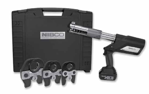
42 Revised 12/19/2012 NIBCO Press System Tools PC-280 1/2" through 4" MATERIAL LIST MODEL NO. DESCRIPTION LBS. PC-280 Pressing Tool with 2-18V, 3.0 Ah Lithium-ion batteries, 110V battery charger & case PC-10S 1/2" Standard Pressing Jaw (for PC-100 or PC-280) 4.14 PC-11S 3/4" Standard Pressing Jaw (for PC-100 or PC-280) 4.18 PC-12S 1" Standard Pressing Jaw (for PC-100 or PC-280) 4.52 PC-13S 1 1/4" Standard Pressing Jaw (for PC-100 or PC-280) 4.30 PC-14S 1 1/2" Standard Pressing Jaw (for PC-100 or PC-280) 9.61 PC-15S 2" Standard Pressing Jaw (for PC-100 or PC-280) 9.26 PC-16S PC-17S 1/2"-1 1/4" (4 jaws) Standard Press Jaw Kit w/case (for PC-100 or PC-280) /2"-2" (2 jaws) Standard Press Jaw Kit w/case (for PC-100 or PC-280) PC-2 2 1/2" Pressing Chain w/case (for PC-100 or PC-280) PC-3 3" Pressing Chain w/case (for PC-100 or PC-280) PC-4 4" Pressing Chain w/case (for PC-100 or PC-280) PC /2", 3" & 4" Pressing Chain Kit (for PC-100 or PC-280) PC-5 PC-5 Pressing Chain Adapter Jaw (note: must be used with 2 1/2", 3" & 4" chains) 7.01 PC-7L 18V, 3.0Ah Lithium-ion Battery (for PC-280 or PC-20M) 1.30 PC-8L 110V Battery Charger (for PC-4ML or PC-7L) 2.20 PC-9L AC Adapter (for PC-280 or PC-20M) 1.70 PC-10S thru PC-15S Standard Pressing Jaw PC-2 thru PC-4 Pressing Chain PC-7L 18V, 3.0 Ah Lithium-ion Battery PC-280 Pressing Tool PC-5 Pressing Chain Adapter Jaw PC-8L 110V Battery Charger PC-280C Plastic Replacement Case for PC-280 Tool 7.50 PC-2C Metal Replacement Case for PC-2 or PC-3 Chain 8.10 PC-4C Metal Replacement Case for PC-4 Chain 8.10 PC-234C Plastic Replacement Case for PC-234 Chain Kit 7.72 PC-16SC Metal Replacement Case for PC-16S (1/2" - 1 1/4" Jaws) 8.10 PC-17SC Metal Replacement Case for PC-17S (1 1/2" - 2" Jaws) 4.40 PC-51 1/2" - 2" Deburring Tool 0.92 PC-51 1/2" - 2" Deburring Tool PC-9L AC Adapter
 11.")
 2.")
 2.07 PC-4ML 18V, 1.")
 2.20 PC-9L AC Adapter (for PC-280 or PC-20M) 1.")

43 NIBCO Press System Tools PC-20M 1/2" through 1" MATERIAL LIST MODEL NO. DESCRIPTION LBS. PC-20M Mini Pressing Tool, 2-18V, 1.3 Ah Lithium-ion batteries, 110V charger & case (NO jaws) PC-200M Mini Pressing Tool, 3 Jaws, 2-18V, 1.3 Ah Lithium-ion batteries, 110V charger & case PC-20M Mini Pressing Tool PC-1M 1/2" Jaw (for Mini Pressing Tool - PC-10M or PC-20M) 2.09 PC-2M 3/4" Jaw (for Mini Pressing Tool - PC-10M or PC-20M) 2.05 PC-3M 1" Jaw (for Mini Pressing Tool - PC-10M or PC-20M) 2.07 PC-4ML 18V, 1.3Ah Lithium-ion Battery (for PC-20M) 0.80 PC-7L 18V, 3.0Ah Lithium-ion Battery (for PC-280 or PC-20M) 1.30 PC-8L 110V Battery Charger (for PC-4ML and PC-7L) 2.20 PC-9L AC Adapter (for PC-280 or PC-20M) 1.70 PC-20MC Plastic Replacement Case for PC-10M & PC-20M) 4.00 PC-50 1/2" - 1" Deburring Tool 0.42 PC-200M Mini Pressing Tool with 1/2", 3/4" and 1" Jaws PC-1M, 2M, 3M Mini Pressing Jaw PC-4ML 18V, 1.3 Ah Lithium-ion Battery PC-8L 110V Battery Charger PC-50 1/2" - 1" Deburring Tool PC-7L 18V, 3.0 Ah Lithium-ion Battery PC-9L AC Adapter

44 NIBCO Press System Tools PC-280 & PC-20M FEATURES TOOLS Light weight Easy to handle / simple design Jaws rotate 350 No calibration necessary No complicated switches or controls Mini: Ergonomic compact design is easy to use in tight spaces Interruptible crimp cycle Can begin crimp, stop to align and level fitting / tube, and complete crimp PC-100 and PC-10M Accessories MATERIAL LIST MODEL NO. DESCRIPTION LBS. PC-6 12V, NiMH Battery - 2.6Ah for PC PC-7 12V, NiMH Battery - 3.0Ah for PC PC-8 120V Standard Battery Charger for PC-6 or PC PC-9 AC Adapter for PC-100 Press Tool 1.32 PC-4M 1.3 Ah NiCd 9.6V Battery for Mini Pressing Tool 0.85 PC-5M 120V Charger for Mini Pressing Tool 1.13 PC-100C Metal Case for PC-100 Tool Battery Can be changed during crimp cycle Lithium-ion has short charging cycle and larger capacity AC Power Adapter Converts the tool to electric power Allows continuous use Service light Illuminates at 10,000 cycles Tool will not stop operating when light illuminates intervals, tool functions & faults Hydraulic Pressure Check (HPC) An audible warning signal sounds if adequate working pressure is not achieved PC-4M 9.6V, 1.3 Ah NiMH Battery PC-7 12V, 3.0 Ah NiMH Battery PRESSING CHAINS (2 1/2" to 4" ONLY) Uniform crimp Maintains proper pipe alignment Easy to install and remove Once secured to fitting, chain cannot fall off prior to crimp Chain easily removed post crimp Crimp Identification Easy to identify crimp has been made from a distance PC-8 120V Battery Charger PC-9 AC Adapter
45 NIBCO Press System Approved Tool and Jaw Compatibility Matrix Only use pressing tools, jaws and chain sets that have been tested and approved for use with NIBCO Press System fittings and valves. approved PRESSING TOOLS SIZE 1/2-1 1/2-2 2½ - 4 YES YES YES YES YES YES YES YES YES YES YES YES YES YES YES YES YES YES YES YES YES YES YES YES YES YES YES AC ECO YES YES YES YES YES YES YES YES YES YES YES YES YES YES YES For the latest listing of approved Pressing tool, jaw and chain combinations, visit nibco.com. NIBCO recommends minor tool service performed once per year and major service every three years. For technical or service assistance, contact NIBCO Technical Services RIDGID is a registered trademark of RIDGID Inc. ProPress is a registered trademark of Viega NA. ROMAX is a registered trademark of ROTHENBERGER USA LLC VIRAX is a registered trademark of The Stanley Works. CAUTION: NIBCO Press Fittings and Valves (2½, 3, 4 ends) to be installed ONLY with NIBCO Pressing Tools & Chains.
46 Engineering Data

47 NIBCO Press System Engineering Data Copper and Copper Alloy Fittings Standards O-Ring seal joints are not new to the piping industry, but joining techniques like the NIBCO Press System are providing new alternatives for copper piping assembly. Although there are no nationally recognized standards for these fittings, NIBCO has relied on its century of experience in copper and brass piping products to design the best performing and most dependable line of fittings possible. Applications The NIBCO Press System fittings are designed to join with ASTM B 88 seamless copper water tube in residential and commercial potable, hot, chilled and process water applications for plumbing and HVAC systems. Copper and copper alloy materials and EPDM elastomeric seals have a long history of compatibility with common chemicals used in these systems. A chemical resistance chart should always be referenced when other fluids are to be introduced. NOTE: FLUIDS CONTAINING HYDROCARBONS ARE NOT COMPATIBLE WITH THE EPDM SEAL. Pressure/Temperature Limitations -20 F to 250 F up to 200 PSIG, non-shock working pressure. Materials: ASTM B 75 Alloy C12200 BS EN 1982:1999 Modified Alloy CC491K European Red Brass comparable to ASTM B 62 EPDM O-Rings compliant with BS EN Flow area consistent with ASME B16.22 NIBCO Press Fittings meet all performance requirements of ASME B16.22 and B16.18 NOTE: Freezing Weather Precaution Subsequent to testing a piping system, valve should be in an open position to allow complete drainage. Performance In the absence of a nationally recognized standard, the following performance tests were developed and conducted. The fitting dimensions, materials of construction and performance tests were witnessed and verified by internationally recognized Underwriters Laboratories, Inc. A letter of verification is available upon request: 1. Dimensional Verification a. Inside diameter of press cup and waterway b. Outside diameter of press cup and waterway c. Wall thickness d. Threaded ends conformance to ASME B Hydrostatic Minimum Burst Strength Pressure a. Fitting samples hydrostatically tested to a minimum of 600 PSI (three times the rated internal working pressure) at 73 F. 3. Unrestrained Hydrostatic Pressure Test at 68 F (20 C) and 200 F (93 C) a. Fitting assemblies were filled with water and pressurized to 600 PSIG at 68 or 200 F for 48 hours. 4. Static Torque a. Fittings were filled with water, had a minimum torque applied and released. Each fitting was then pressurized to 400 PSIG for 48 hours. 5. Bending Test a. A sample fitting was installed between two equal lengths of harddrawn copper tubing supported six (6) feet apart. A concentrated load was applied to the center of the fitting. The assembly was subjected to 400 PSIG water pressure for one (1) hour. 6. Vacuum Pressure Test a. Fittings were subjected to a vacuum pressure of 24.5 inches of mercury for one (1) hour. 7. Cyclic Pressure Test a. Fittings were subjected to a hydraulic shock pressure of 400 PSIG for 10,000 cycles. 8. Vibration Test a. Fitting assemblies were subjected to a hydrostatic cyclic vibration test at 350 PSIG for 1,000,000 cycles. After cycling, the assemblies were pressurized to 400 PSIG for 30 minutes. 9. Thermocycling Test a. Fitting and tube assemblies were filled with air and pressurized to 100 PSIG. The water temperature was cycled from 68 F to 200 F for 2,500 cycles. Each temperature was held for 2 minutes and changed within two (2) minutes. 10. Dynamic Torque at 68 F (20 C) and 200 F (93 C) a. Fittings were assembled between two lengths of hard-drawn copper tubing. With one tube fixed, the other tube twisted ±5 for 10,000 cycles at 68 F (20 C) or 200 F (93 C). Each assembly was then subjected to 400 PSIG water pressure at 68 F (20 C) or 200 F (93 C) for 48 hours. Tests were performed with K, L and M hard drawn-copper tubing. A minimum of one fitting of each configuration of each size was tested.
48 NIBCO Press System Sample Specification FITTINGS 2" and Smaller: Fittings shall comply with NSF 61, CSA, UPC and be approved by the local jurisdiction. The NIBCO Press System may be used at the contractor s option for the following building services piping - 20 F to +250 F up to 200 PSI: ter Heating Service Wrot copper press fittings shall be made from commercially pure copper mill products per ASTM B 75 Alloy C Cast copper alloy press fittings shall be made from materials with a minimum of 78% copper and a maximum of 15% zinc. The press fittings connections shall be compatible with seamless K, L or M copper tube made to ASTM B 88. Fittings shall have a maximum non-shock working pressure of 200 PSI between the temperatures of -20 F and +250 F. Elastomeric seals shall be made of EPDM material, and the fittings shall be manufactured with an inboard bead design. All fittings shall be installed in accordance with the manufacturer s installation instructions and according to local plumbing and mechanical codes. The press-to-connect joint shall be made with pressing tools and jaw sets recommended and authorized by NIBCO. 2½" through 4": Fittings shall comply with NSF 61, CSA, UPC and be approved by the local jurisdiction. The NIBCO Press System may be used at the contractor s option for the following building services piping - 20 F to +250 F up to 200 PSI: ter Heating Service Wrot copper press fittings shall be made from commercially pure copper mill products per ASTM B 75 Alloy C Cast copper alloy press fittings shall be made from materials with a minimum of 78% copper and a maximum of 15% zinc. The press fittings connections shall be compatible with seamless K, L or M copper tube made to ASTM B 88. Fittings shall have a maximum non-shock working pressure of 200 PSI between the temperatures of -20 F and +250 F. Elastomeric seals shall be made of EPDM material, and the fittings shall be manufactured with an inboard bead design. All fittings shall be installed in accordance with the manufacturer s installation instructions and according to local plumbing and mechanical codes. The press-to-connect joint shall be made with pressing tools and jaw sets recommended and authorized by NIBCO.
49 NIBCO Press System Sample Specification VALVES 2" and Smaller Ball Valves: (On/Off, Isolation or Throttling) Ball valves with male or female press-to-connect ends shall be rated at 200 PSI CWP to +250 F maximum. Valves shall be manufactured in accordance with MSS SP-110 and constructed of dezincification resistant cast bronze bodies. No brass containing more than 15% zinc shall be approved. Valve shall have reinforced PTFE seats, blow-out proof stem, full-port ball, chrome/nickel plated ball or 316 SS ball for aggressive water conditions. Where piping is to be insulated, ball valves shall be equipped with 2 extended handles of non-thermal conductive material. Handle to have extended sleeve incorporating an insulation plug to provide a vapor barrier and allow valve operation without disturbing the insulation, and a memory stop, which can be set after installation. Acceptable Valves: (non-insulated lines): NIBCO PC585-70, PF or PS (Chrome/nickel plated ball) NIBCO PC , PF , PS or PCM (316 SS ball) Acceptable Valves: (insulated lines): NIBCO PC NS, PF NS or PS NS (Chrome/nickel plated ball) NIBCO PC NS, PF NS or PCM NS (316 SS ball) (Note to Specifier: Include press gate valves in addition/in lieu of press ball valves for ON/OFF and isolation services if requested or required.) 2" and Smaller Gate Valves: (On/Off and Isolation) Gate valves with male or female press-to-connect ends shall be rated to 200 PSI CWP at +250 F maximum. Valves shall be manufactured in accordance with MSS SP-80. Valve body, bonnet and wedge to be manufactured of dezincification resistant cast bronze (ASTM B 62). Stems shall be of silicon bronze (ASTM B 371) or low zinc alloy (ASTM B 99). Non-asbestos packing and malleable or ductile iron hand-wheel shall be standard. Acceptable Valves: NIBCO PF111 or PS111 - Rising Stem Gate Valve NIBCO PF113 or PS113 - Non-Rising Stem Gate Valve Acceptable Valves: NIBCO PF413-Y or PS413-Y - Y Pattern, Swing Type Check Valve NIBCO PF480-Y or PS480-Y - In-line spring loaded Silent Check Valve Drain Valves At all low points in water piping to be drained or vented, provide 1/2 or 3/4" ball valves with male or female press-to-connect ends by hose-end drain valves. Valves shall be rated by 200 PSI CWP to +250 F maximum. Valves shall be manufactured in accordance with MSS SP-110. Valves to be constructed of dezincification resistant cast bronze bodies. Valve shall have reinforced PTFE seats, blow-out proof stem, and be full port. All valves shall be provided with 3/4 hose connection with cap and chain. Acceptable Valves: NIBCO PS HC or PF HC 2 1/2" thru 4" Butterfly Valves: (On/Off, Isolation or Throttling) Butterfly valves with female press-to-connect ends shall be rated at 200 PSI CWP to +250 F maximum. Valves shall be manufactured in accordance with MSS SP-67 and constructed of a ductile-iron body, for bubble-tight shutoff, extended-neck for insulation, disc and lining suitable for potable water, valves shall be suitable for bi-directional dead end service at full rated pressure, one-piece Type 416 stainless-steel stem, copper bushing, fasteners and pins shall not be used to attach stem to disc, no pins or fasteners in waterway, aluminum-bronze disc, and molded-in EPDM seat (liner). Acceptable Valves: NIBCO PFD2000 Series 2" and Smaller Globe and Angle Valves: (Throttling Service) Globe and angle valves with male or female press-to-connect ends shall be rated to 200 PSI CWP at +250 F maximum. Valves shall be manufactured in accordance with MSS SP-80. Valve body, bonnet and wedge to be manufactured of dezincification resistant cast bronze (ASTM B 62). Stems shall be of silicon bronze (ASTM B 371) or low zinc alloy (ASTM B 99). Non-asbestos packing and malleable or ductile iron hand-wheel shall be standard. Acceptable Valves: NIBCO PF211-Y or PS211-Y - Globe Valve NIBCO PF311-Y or PS311-Y - Angle Valve 2" and Smaller Check Valves: (Back Flow Prevention) Check valves (Y pattern, swing type or in-line) with male or female pressto-connect ends shall be rated at 200 PSI CWP to +250 F maximum. Valves shall be manufactured in accordance with MSS SP-80. Body and cap to be manufactured of dezincification resistant cast bronze (ASTM B 62 or ASTM B 584 Alloy C84400). Valves to have PTFE seat disc.
50 Installation Instructions
51 NIBCO Press System Installation Instructions NIBCO Press System The NIBCO Press System, when used with tested and authorized pressing tools and jaws, is designed to mechanically crimp fittings and valves onto copper tubing to create a watertight, permanent seal. When the switch on the pressing tool is depressed, an internal motor powers a hydraulic pump which forces fluid into the cylinder of the tool, forcing the ram forward and applying thousands of pounds of crimping force onto the specially designed fittings and valves. System Components Fittings and Valves NIBCO Press System copper or bronze fittings and valves Tubing ASTM B 88 seamless Hard Drawn Copper Water Tube: Types K, L and M. Pressing Tools, Chains and Jaws The pressing tool, chain and jaw are important parts of ensuring a reliable, permanent connection between NIBCO Press System fittings and valves and the copper water tube. CAUTION Use only pressing tools and jaw sets that have been tested and authorized for use with NIBCO Press System fittings and valves (1). Use of unauthorized pressing tools and/or jaws may result in an improper seal that could cause extensive property damage. (1) See approved tool and jaw compatibility matrix on page 52. Pressing Tool Safety Press System fittings and valves. Other uses or modification of the jaws for other applications may damage the press tool, damage the jaws and/or cause personal injury. or hands can be crushed, fractured or amputated if they become caught between the jaw tips or between the jaw and any other object. welded, ground, drilled or modified in any manner can shatter during crimping resulting in serious injury. Discard the entire damaged jaw set. Replace with a new jaw set. NOTE: Consult manufacturer's pressing tool and jaw set operators manual to determine replaceable jaw set components. WARNING: Please read these installation instructions and the manufacturer's pressing tool and jaw operators manual(s) carefully prior to installation of the NIBCO Press System. Failure to understand and follow the contents of this manual may result in extensive property damage, severe personal injury or death. Please contact NIBCO Technical Services at if you have installation questions.
 and jaw sets according to the procedure outlined in the pressing tool instruction manual prior to beginning installation.")
.")


52 NIBCO Press System Installation Instructions Installation Instructions for 1/2" - 2" Press Fittings and Valves WARNING: To prevent serious injury, inspect the pressing tool, battery charger (if applicable) and jaw sets according to the procedure outlined in the pressing tool instruction manual prior to beginning installation. Failure to clean jaws can result in an improper connection that can lead to extensive property damage. 2. Insert the tube into the fitting or valve using a twisting motion. Make sure that the tube is fully inserted into the fitting stop or shoulder. 3. Mark the tube with a permanent marker to indicate the proper tube insertion depth (Figure 3). Work Area Set-Up To prevent serious injury, proper set-up of the pressing tool and work area is required. The following procedure should be followed: 1. Check work area for: 2. Follow the tool set-up procedures specified in the manufacturer's pressing tool instruction manual. Preparing the Copper Tube 1. Select clean, undamaged copper tube and cut to desired length. Cut tube end square using a tube cutter or fine-toothed saw (Figure 1). Figure 3 Inserting the tube to proper depth 4. Refer to the minimum insertion depth table for correct depths Tube Size Insertion Depth (min.) Inches Inches mm 1/2 11/ /4 7/ / CAUTION: Tubing that is difficult to insert may have burrs or could be out-of-round. Burrs must be removed and tubing end should be undamaged. Make sure tube is inserted to the proper depth. Failure to do so may result in an improper seal. Figure 1 Cut tube to desired length using a tube cutter 2. Deburr the tube inside and outside diameter using a half-round file or a deburring tool. 3. Clean the tube end of all dirt, oil and grease. (Emery cloth or sandpaper to clean the tube or remove oxidation is not required.) Attaching Pressing Jaws 1. Make sure the battery is removed or the cord is unplugged on the pressing tool prior to attaching or changing the crimp jaws. 2. Push and twist to open the jaw set mounting pin. (Figure 4). Inserting the Tube into the Fitting or Valve 1. Check the fitting to make sure the EPDM seal is in place, clean and free of oil and grease (Figure 2). Figure 4 Pushing and twisting to open the jaw set mounting pin 3. If press tool contains a jaw set, slide it out of the crimping tool. Figure 2 Check for EPDM Seal WARNING: Never lubricate the EPDM seal in the NIBCO Press System fitting or valve with anything other than water. Oil-based lubricant, dirt or debris may damage the seal. An improper seal can lead to extensive property damage.

. 5.")

53 NIBCO Press System Installation Instructions 4. Select the jaw set that corresponds to the size of the joint to be crimped and insert the jaw set into the pressing tool (Figure 5). Figure 8 Jaw set should be square to tubing Figure 5 Inserting the NIBCO Press System jaw 5. Push the jaw set mounting pin until it clicks into position. NOTE: The tool will not work unless the pin is fully engaged. Crimping a NIBCO Press System Fitting or Valve 1. Make sure the tubing is inserted to the proper depth in the fitting, and that tube and fitting are aligned properly. (Figure 6). 5. Once the crimp is complete, press the jaw arms to open the jaw and remove from the fitting. If the tool malfunctions, please refer to the tool instruction manual for troubleshooting suggestions. CAUTION Avoid sharp edges that may have formed on the fitting during the crimping operation. Inspecting the Crimp 1. Inspect the crimped fitting to ensure proper crimp. NOTE: The use of the NIBCO Press System jaw will produce a unique witness mark N on the crimped fitting. 2. Inspect the crimped fitting checking the connection for the following problems: Figure 6 Inserting the tube to proper depth 2. Squeeze jaw arms to open the jaw set. 3. Place the open jaws around the fitting and ensure that the contour of the jaw is properly aligned with the contour of the fitting (Figure 7). If one or more of these problems are found, a new section of tubing and a new fitting will need to be prepared, installed and crimped. 3. Test the NIBCO Press System in accordance with normal practice and to local jurisdiction piping code. Figure 7 Open the jaw set and place around the fitting 4. Make sure the tool is square to the tubing and depress the switch (Figure 8). Once the crimp cycle begins and the rollers contact the jaw arms, the tool will complete the crimp cycle, as long as the trigger is depressed.


54 NIBCO Press System Installation Instructions Installation Instructions for 2 1/2" - 4" Press Fittings and Valves WARNING: To prevent serious injury, the pressing tool, battery charger (if applicable) and pressing chains should be inspected according to the procedure outlined in the pressing tool instruction manual prior to beginning installation. Failure to clean pressing chains can result in an improper connection that can lead to extensive property damage. Work Area Set-Up To prevent serious injury, proper set-up of the pressing tool and work area is required. The following procedure should be followed: 1. Check work area for: 2. Follow the tool set-up procedures specified in the pressing tool instruction manual. Preparing the Copper Tube 1. Select clean, undamaged copper tube and cut to the desired length. Cut tube end square using a tube cutter or fine-toothed saw (Figure 1). Figure 4: Deburr outside diameter using a half-round file 4. Clean the tube end of all contamination, oils and shavings. A smooth transition chamfer is recommended to ease tube insertion past the seal. (Emery cloth or sandpaper to clean the tube or remove oxidation is not required.) Inserting the Tube into the Fitting or Valve 1. Check the fitting to make sure that the seal is in place and is free of oil or grease. Only original NIBCO EPDM seals are to be used when making a press connection with NIBCO Press System fittings and valves. If it is necessary to lubricate the seals, use water only. DO NOT use any petroleum-based lubricants (Figure 5). Figure 5: Check for EPDM seal Figure 1: Cut tube to desired length using s tube cutter 2. Deburr the tube inside diameter using a half-round file or deburring tool. Remove any copper shavings or filings (Figures 2 & 3). WARNING: Never lubricate the EPDM seal in a NIBCO Press System fitting or valve with anything other than water. Oil-based lubricants, dirt or debris may damage the seal. An improper seal can lead to extensive property damage. 2. Mark the proper insertion depth on the tube with a permanent marker prior to insertion, based on insertion depth chart. Refer to minimum insertion depth table for correct depths. Figure 2: Deburr inside diameter using a half-round file NIBCO Press System Insertion Depth Chart Tube Size 2 1 /2 3 4 Insertion Depth (min.) 1 1 /2 1 5 /8 2 1 /8 WARNING: If tube is not inserted to the proper depth, an inadequate seal may result. 3. Insert the tube into the fitting or valve using a twisting motion. Make sure that the tube is fullly inserted into the fitting or valve. If tube is not inserted to the proper depth, an inadequate seal may result. Figure 3: Deburr inside diameter deburring tool 3. Deburr the tube outside diameter using a half-round file to prevent damage to the EPDM seal (Figure 4). CAUTION: Tubing that is difficult to insert may have burrs or could be out-of-round. Burrs must be removed and tubing end should be undamaged. Make sure tube is inserted to the proper depth. Failure to do so may result in an improper seal.


55 NIBCO Press System Installation Instructions Crimping a NIBCO Press System Fitting or Valve CAUTION: NIBCO Press Fittings and Valves (2½, 3, 4 ends) to be installed ONLY with: 3 (PC-3), 4 (PC-4) 1. Make sure that the battery is removed or that the cord is unplugged on the pressing tool prior to attaching or changing the adapter jaw. 2. Select the correct size pressing chain. Pull the pin on the chain which allows the segments to open. Position the chain on the raised bead and wrap the chain around the fitting with the "pipe side" designation facing the tube. When the chain is fully wrapped around the fitting, reinsert the pin to secure the chain on the assembled joint. Visually inspect the mark made for insertion depth, to ensure the tube remained in position (Figure 6). Figure 8: Placement of adapter jaw into pressing chain 5. Make sure the tubing is inserted to the proper depth in the fitting or valve, and that the tube and fitting or valve are aligned properly. 6. With the pressing tool perpendicular to the tube, begin the pressing cycle by pulling the trigger of the pressing tool. 7. Allow the pressing cycle to complete. Remove the pressing tool and adapter jaw from the pressing chain. Remove the pressing chain from the fitting. If the tool malfunctions, please refer to the tool instruction manual for troubleshooting suggestions. CAUTION: Avoid sharp edges that may have formed on the fitting during the crimping operation. Inspecting the Crimp 1. Inspect the crimped fitting or valve to ensure proper crimp. The final crimp should appear pressed uniformly around the fitting or valve (Figure 9). Figure 6: Placement of the pressing chain onto fitting or valve 3. Release the pin (push and twist) on the jaw holder of the pressing tool, and install the adapter jaw on the tool. Return the pin to its original position, securing the jaw. The red sleeve on the tool must be in the back position to allow for crimping sizes 2½, 3 and 4. (The red sleeve in the forward position allows for use with ½ - 2 standard pressing jaws.) Rollers on the pressing tool must be in the forward position to allow the red sleeve to move forward (Figure 7). Figure 9: Inspection of final crimp NOTE: The use of the NIBCO Press System chain will produce a unique witness mark N. Figure 7: Placement of adapter jaw into the tool 4. Squeeze adapter jaw arms to open the jaw. Rollers must be fully retracted to open the adapter jaw. Place the open adapter jaw into the grooves in the pressing chain and let go of the jaw arms (Figure 8). 2. Inspect the crimped fitting checking the connection for the following problems: If one or more of these problems are found, a new section of tubing and a new fitting will need to be prepared, installed, and crimped. 3. Test the NIBCO Press System in accordance with normal practice and to local jurisdiction piping code.
56 NIBCO Press System Testing Instructions for Fittings & Valves with Leak Detection PRESSURE TESTING: AIR LEAK TESTING WATER LEAK TESTING
57 NIBCO Press System Installation Instructions Minimum Distance Between Joints To prevent distortion of the tubing, certain fitting sizes require a minimum distance between crimp joints (refer to Chart 1 below). Failure to provide this minimum distance may result in an improper seal. Spacing 1. Sufficient clearance must be left around each joint to allow room for the pressing tool and jaw to be attached without interference. Clearance Requirements Standard Jaw Sets Tool perpendicular to wall A (min.) Tube Dia. Inches mm 1 2"* "* 0 0 1"* "* "* 0 0 2"* " 3 8" 10 3" 3 8" 10 4" 3 8" 10 *No minimum distance required. A (min.) B (min.) Tube Dia. Inches mm Inches mm 1 /2 15 / / /4 7 / / / / /4 1 1 / / / / /8 111 Tool angled to wall System Support CAUTION In any installation, the system should be suported to ensure the minimum stress is imposed on the tube and joints. The NIBCO Press System should be supported in accordance with normal practice and to local jurisdiction piping code. Annealing of Copper Tube A NIBCO Press System installation should not be conducted within 12" of a brazed joint. The high temperature required for capillary joinery may cause the copper tube to become annealed and render it too soft for proper crimping. However, a NIBCO Press System product may be crimped adjacent to a soldered joint, as normal temperatures created by silver soldering are not hot enough to cause the copper tube to become annealed. CAUTION Brazing or soldering should not be conducted within 12" of an existing NIBCO Press System connection as this may damage the EPDM seal. If there is any concern about heat damage to the o-ring, a cold, wet cloth should be wrapped around the crimped connection Tube Dia. A (min.) B (min.) C (min.) Inches mm Inches mm Inches mm 1 /2 1 1 / / / / / / / / /4 1 1 / / / /2 2 1 / / / / /2 3 5 / / / / / / /4 108 NOTE: Clearance dimensions for 2 1 /2", 3" & 4" are for wrapping pressing chains around fittings.
58 NIBCO Press System Frequently Asked Questions What is the NIBCO product offering? The NIBCO Press System features a full range of copper and copper alloy fittings, commercial valves, accessories and pressing tools, jaws and chains for use with K, L and M copper water tube. What is the system temperature rating? The NIBCO Press System is rated at 200 PSIG over a temperature range of -20 F to 250 F. What are the approved system applications? Approved applications include residential and commercial potable, hot, chilled and process water for plumbing and HVAC systems. The NIBCO Press System is designed for use with water glycol mixtures of ethylene or propylene glycol up to 50% at 200 F. What was the testing protocol for the NIBCO Press System fittings and valves? NIBCO Press System fittings and valves were subjected to a wide range of performance tests including dimensional verification, thread end specification, hydrostatic burst strength, unrestrained pressure, static torque, bending, vacuum pressure, cyclic pressure, vibration, thermo-cycling and dynamic torque. The testing protocol included testing to a 3X safety factor above the 200 PSIG system rating. NIBCO testing was witnessed and validated by the internationally recognized Underwriters Laboratories, Inc. (UL). Can other available pressing tools and jaws be used on the NIBCO Press System? See page 52 for a complete listing of approved tools and jaws. Can a NIBCO Press System connection be re-crimped? If for any reason the press cycle is interrupted, it is possible to re-crimp a NIBCO Press System connection. However, when re-crimping the connection, the jaws must be properly aligned so that the crimp is performed in the same location as the original. How long will the EPDM seal last? Accelerated life tests show that the EPDM seals used with the NIBCO Press System fittings and valves have a life expectancy of 50 years. Are NIBCO Press System fittings available with solder or threaded by Press System connection? NIBCO offers many Press System fitting combinations by soldered or threaded connection. Please note, always solder the standard wrot connection first when possible. Prior to soldering, remove the press end EPDM o-ring, solder, allow the fitting to cool, insert the EPDM o-ring, and then Press the connection. Can a fitting be soldered close to a Press System connection? NIBCO recommends soldering at least 12 inches away from the Press System connection. If this length is not possible, either solder the joint prior to connecting the press fitting or wrap the connection with a cold wet cloth. Is the NIBCO Press System approved for underground use? In accordance with local plumbing codes, the NIBCO Press System can be installed underground. Is the NIBCO Press System compatible with standard disinfectant cleaning agents commonly utilized in a new water system? Yes, the NIBCO Press System is typically compatible. For specific cleaning agent compatibility, contact NIBCO Technical Services at the below noted number.
59 NIBCO Press System Fittings Limited Warranty NIBCO INC. warrants: Press System fittings to be free from defects in materials and workmanship under normal use and service, for a period of 50 years from the Warranty Commencement Date. The Warranty Commencement Date for NIBCO Press System fittings shall be the date upon which the fitting is installed. NIBCO does NOT warrant against failure of NIBCO Press System fittings (referred to hereafter as product ) for: 1. any product, parts or systems which are not manufactured or sold by NIBCO INC.; 2. any product which is used for any purposes other than a purpose authorized by NIBCO INC.; 3. any product not installed in accordance with either the recommended installation guidelines provided by NIBCO INC. and/or applicable plumbing codes; 4. damage to the product caused by, contributed in whole or in part by, or resulting from, any of the following: a. abuse, misuse, mishandling, tampering, neglect or accidental damage, such as, without limitation, vandalism b. natural disasters, such as, without limitation, flooding, windstorm and lightning c. attachments or modifications to the product that are not authorized by NIBCO INC. d. external causes, where external, physical or chemical qualities produce damage to the product, such as, without limitation, variation in water quality, aggressive water or an unsuitable or hostile environment, or e. any other cause beyond the control of NIBCO INC. NIBCO shall NOT be liable under any circumstances for any other direct or indirect, incidental or consequential damages of any kind, including but not limited to loss of business, lost profits, mold intrusion, water damage, etc. The liability of NIBCO under this warranty is solely limited to the repair or replacement, including installation expenses, of any product that has been determined by NIBCO INC., or an authorized representative or agent thereof, to contain a defect in material or workmanship. This warranty is the only warranty for the product provided by NIBCO INC., and is and shall be in lieu of any and all other warranties, expressed or implied, including but not limited to an implied warranty of merchantability, and for all other obligations or liabilities on the part of the Manufacturer. No employee of NIBCO INC., or any other distributor, agent or other person or business, is authorized to make any other warranty on behalf of NIBCO INC. In the event any defect occurs which is believed to be covered by this warranty, NIBCO Technical Services should be immediately contacted either in writing or by telephone at NIBCO Technical Services will make further arrangements for the product s return to NIBCO INC. for review and evaluation. In the event that a returned product is determined by NIBCO INC. to be defective, NIBCO INC. will remediate the failure by repairing or replacing the product within a reasonable time, without charge to the owner of the product. This warranty gives you specific legal rights, and you may also have other rights which vary from state to state.
 years from date put into service.")
60 NIBCO Press System Valves NIBCO INC. 125% LIMITED WARRANTY Applicable to NIBCO INC. Pressure Rated Metal Valves NIBCO INC. warrants each NIBCO pressure rated metal valve to be free from defects in materials and workmanship under normal use and service for a period of five (5) years from date put into service. In the event any defect occurs which the owner believes is covered by this warranty, the owner should immediately contact NIBCO Technical Services, either in writing or by telephone at (888) or (574) The owner will be instructed to return said product, at the owner s expense, to NIBCO INC., or an authorized representative for inspection. In the event said inspection discloses to the satisfaction of NIBCO INC. that said valve is defective, it will be replaced at the expense of NIBCO INC. Replacements shall be shipped free of charge to the owner. In the event of the replacement of any valve, NIBCO INC. shall further pay the owner the greater of Twenty-Five (25%) Percent of the price of the valve according to the NIBCO INC. published suggested list price schedule in effect at the time of purchase, or Ten ($10.00) Dollars, to apply on the cost of the installation of said replacement valve. TO THE EXTENT PERMITTED BY LAW, THIS WARRANTY SPECIFICALLY EXCLUDES INCIDENTAL AND CONSEQUENTIAL DAMAGES OF EVERY TYPE AND DESCRIPTION RESULTING FROM ANY CLAIMED DEFECT IN MATERIAL OR WORKMANSHIP, INCLUDING BUT NOT LIMITED TO, PERSONAL INJURIES AND PROPERTY DAMAGES. Some states or countries do not allow the exclusion or limitation of incidental or consequential damages so these limitations may not apply to you. TO THE EXTENT PERMITTED BY LAW, IMPLIED WARRANTIES OF MERCHANTABILITY AND FITNESS FOR A PARTICULAR PURPOSE ARE LIMITED IN DURATION. This warranty gives you specific legal rights, and you may also have other rights which vary from state to state and country to country. HOW MANY TO ORDER POLICY ON RETURNS TO FACTORY NO NIBCO how to order TECHNICAL ASSISTANCE NIBCO INC. USA To the best of our knowledge the information contained in this publication is accurate. However, NIBCO does not assume any liability whatsoever for the accuracy or completeness of such information. Final determinations of the suitability of any information or product for the use to be contemplated is the sole responsibility of the user. The manner of that use, and whether there is any infringement of patents, is also the sole responsibility of the user.
61 NOTES
62 NOTES

63 globally connecting It s a new age of business, and a new way at NIBCO. From Elkhart, Indiana to Lodz, Poland, and points beyond, our company has integrated manufacturing, distribution, and networked communications to provide a seamless source of information and service, 24 hours a day, 7 days a week. But this integration hasn t happened overnight. It s been part of a long-term strategic process that has pushed us to reconsider every aspect of our business. The result? We re a vertically integrated manufacturer with the products and systems in place to deliver low cost and high quality. NIBCO products are manufactured under a Quality Management System conforming to the current revision of ISO-9001 International Standards. We know the flow control industry is only going to get more demanding, and we are more than ready. We will continue to lead. That s what NIBCO is all about. World Headquarters Elkhart, Indiana MANUFACTURING DISTRIBUTION INTERNATIONAL Metal Valves and Fittings Blytheville, Arkansas McAllen, Texas Nacogdoches, Texas Stuarts Draft, Virginia Plastic Pipe, Valves, and Fittings Greensboro, Georgia Goshen, Indiana Lebanon, Ohio Industrial Plastics * * * * * * Charlestown, Indiana International Reynosa, Mexico Lodz, Poland *Denotes U.S. and International Direct Shipping Locations * U.S. Distribution Centers Elkhart, Indiana Global Offices Elkhart, Indiana Lodz, Poland


64 FEATURING NIBCO SYSTEMS C-NPS-0812 NIBCO Press System FITTINGS S-t o-metal transition fittings fire protection fittings * fittings BlazeMaster *Weighted average lead content 0.25% VALVES & ACTUATION * valves *Weighted average lead content 0.25% CHEMTROL Thermoplastic pipe, valves and fittings in PVC, Corzan CPVC, polypropylene and PVDF Kynar Corzan is a registered trademark of Arkema Inc. enibco NIBCO INC MIDDLEBURY STREET DOMESTIC CUSTOMER SERVICE TECHNICAL SERVICE INTERNATIONAL OFFICE WORLD HEADQUARTERS ELKHART, IN PHONE: PHONE: PHONE: +1/ WEB: USA FAX: FAX: FAX: +1/ C-NPS NIBCO INC., All Rights Reserved. Printed in U.S.A.
catalog C-NPS-1014 NIBCO Press System
 catalog C-NPS-1014 ahead of the flow NIBCO Press System Business-to-Business Solutions Look to NIBCO for technology leadership. The velocity with which e-business evolves demands that new products and
CATALOG C-NPS-0618 AHEAD OF THE FLOW NIBCO. Press System
 CATALOG C-NPS-0618 AHEAD OF THE FLOW NIBCO Press System Business-to-Business Solutions Look to NIBCO for technology leadership. The velocity with which e-business evolves demands that new products and
SECTION GENERAL-DUTY VALVES FOR PLUMBING PIPING
 PART 1 - GENERAL 1.1 DESCRIPTION OF WORK A. Provide labor, materials, equipment, and services necessary to install valves required to complete the work indicated on drawings. B. ASME Compliance: 1. ASME
Iron Check Valves Illustrated Index
 Iron Check Valves Illustrated Index Iron Body Swing Check Valve Bronze Mounted or All Iron 125 lb. SWP 200 lb. CWP Iron Body Swing Check Valve Bronze Mounted 250 lb. SWP 500 lb. CWP Iron Body Silent Check
UNIVERSITY SERVICES ANNEX James Madison University Harrisonburg, Virginia State Project Code: Architect s Project Number:
 SECTION 230523 GENERAL DUTY VALVES FOR HVAC PIPING PART 1 - GENERAL 1.1 RELATED DOCUMENTS A. Provisions of the Contract and of the Contract Documents apply to this Section. 1.2 DEFINITIONS A. The following
Valve Selection. 1. Function and service considerations
 1. Function and service considerations Valve Selection Selection Valves serve the purpose of controlling the fluids in building services piping. Valves are produced in a variety of design types and materials.
A. This Section includes general duty valves common to several HVAC piping systems.
 SECTION 23 05 23 - PART 1 - GENERAL 1.1 RELATED DOCUMENTS A. Drawings and general provisions of the Contract, including General and Supplementary Conditions and Division 01 Specification Sections, apply
SECTION GENERAL-DUTY VALVES FOR HVAC PIPING. A. Contents of Division 23, HVAC and Division 01, General Requirements apply to this Section.
 SECTION 23 05 23 PART 1 - GENERAL 1.1 SUMMARY A. Work Included: 1. Gate Valves 2. Balancing Valves 3. Ball Valves 4. Butterfly Valves 5. Swing Check Valves 1.2 RELATED SECTIONS A. Contents of Division
SECTION GENERAL-DUTY VALVES FOR PLUMBING PIPING
 SUNY GENESEO 220523-1 PART 1 - GENERAL 1.1 RELATED DOCUMENTS A. Drawings and general provisions of the Contract, including General and Supplementary Conditions and Division 01 Specification Sections, apply
Michigan State University Construction Standards. GENERAL-DUTY VALVES FOR HVAC PIPING Page
 Page 230523-1 Copyright 2005 by The American Institute of Architects (AIA) Exclusively published and distributed by Architectural Computer Services, Inc. (ARCOM) for the AIA Modified by MSU Physical Plant
SECTION GENERAL-DUTY VALVES FOR PLUMBING PIPING
 SECTION 220523 - GENERAL-DUTY VALVES FOR PLUMBING PIPING PART 1 - GENERAL 1.1 RELATED DOCUMENTS A. Drawings and general provisions of the Contract, including General and Supplementary Conditions and Division
LEAD-FREE * PERFORMANCE BRONZE FITTINGS
 LEAD-FREE * PERFORMANCE BRONZE FITTINGS NIBCO Wrot Copper Solder Fittings manufactured in Stuarts Draft, Virginia, are 3rd party certified to Annex G of NSF/ANSI 61. For our complete offering of wrot copper
Union County Vocational - Technical Schools Scotch Plains, New Jersey
 SECTION 220523 - GENERAL-DUTY VALVES FOR PLUMBING PIPING PART 1 - GENERAL 1.1 SUMMARY A. Section Includes: 1. Brass ball valves. 2. Iron swing check valves. 3. Iron gate valves. 4. Iron globe valves. B.
1.1 PURPOSE A. This section is intended to define the general installation and minimum product requirements for hydronic and steam valves.
 Date Description of Change Pages / Sections Modified ID 6/15/16 Entire document - mgl44 PART 1 - INTRODUCTION 1.1 PURPOSE A. This section is intended to define the general installation and minimum product
Cast-Iron Valves G101 DI BUTTERFLY VALVE LEVER... 2 G401 CI GLOBE VALVE CL G403 CI GLOBE VALVE PN G103 DI BUTTERFLY VALVE GEAR...
 Cast-Iron Valves PAGE G101 DI BUTTERFLY VALVE LEVER.... 2 PAGE G401 CI GLOBE VALVE CL125.... 9 G103 DI BUTTERFLY VALVE GEAR.... 3 G403 CI GLOBE VALVE PN16.... 10 G201 CI Y STRAINER CL125.... 4 G501 CI
Michigan State University Construction Standards. GENERAL-DUTY VALVES FOR PLUMBING PIPING Page
 Page 220523-1 SECTION 220523 - PART 1 - GENERAL 1.1 RELATED DOCUMENTS A. Drawings and general provisions of the Contract, including General and Supplementary Conditions and Division 01 Specification Sections,
SECTION VALVES
 PART 1 GENERAL 1.1 RELATED DOCUMENTS A. Drawings and general provisions of the Contract, including General and Supplementary Conditions Specification Sections, apply to this Section. B. Related Sections:
VALVES. A. Section HVAC Basic Materials and Methods. E. Section Building Automation and Control System Guidelines
 230523 VALVES PART 1: GENERAL 1.01 RELATED SECTIONS A. Section 230500 HVAC Basic Materials and Methods B. Section 230510 Chilled Water System C. Section 230520 Heat Generation D. Section 238216 Coils E.
Division 23 - HVAC Section Switzerland Beallsville K-12 GENERAL DUTY VALVES FOR HVAC PIPING
 SECTION 23 05 23 GENERAL-DUTY VALVES FOR HVAC PIPING PART 1 - GENERAL 1.1 RELATED DOCUMENTS A. Drawings and General Provisions of the Contract, including General and Supplementary Conditions and Division
DIVISION 23 HEATING, VENTILATING, AND AIR CONDITIONING (HVAC) SECTION HVAC VALVES
 SECTION HVAC VALVES") DIVISION 23 HEATING, VENTILATING, AND AIR CONDITIONING (HVAC) SECTION 23 05 23 PART 1 GENERAL 1.01 DESCRIPTION A. Provide valves for the following systems: 1. Heating Hot Water 2. Chilled Water 3. Condenser
DIVISION 23 HEATING, VENTILATING, AND AIR CONDITIONING (HVAC) SECTION 23 05 23 PART 1 GENERAL 1.01 DESCRIPTION A. Provide valves for the following systems: 1. Heating Hot Water 2. Chilled Water 3. Condenser
SECTION VALVES PART 1 - GENERAL
 1.01 RELATED DOCUMENTS SECTION 15100 VALVES PART 1 - GENERAL A. The work in this section includes the furnishing and installation of all control valves and accessories shown on the construction plans and
Hattersley Newman Hender Ltd
 Product Guide Quality Valves from Hattersley WHEN IT REALLY COUNTS, YOU CAN DEPEND ON HATTERSLEY Hattersley Newman Hender is one of the world s premier manufacturers of cast iron, ductile iron and copper
Brown University Revised August 3, 2012 Facilities Design & Construction Standards SECTION HVAC&R VALVES
 SECTION 23 05 23 HVAC&R VALVES PART 1 - GENERAL 1.1 SUMMARY: A. Section includes valves for building services piping. 1.2 GENERAL VALVE APPLICATION REQUIREMENTS: A. Provide valve handle extensions that
SECTION PLUMBING PIPING VALVES AND ACCESSORIES PART 1 - GENERAL
 SECTION 22 10 10 PLUMBING PIPING VALVES AND ACCESSORIES PART 1 - GENERAL 1.1 RELATED DOCUMENTS: A. The Conditions of the Contract and applicable requirements of Division 1, "General Requirements", and
1.2 REFERENCES.1 American National Standards Institute (ANSI)/ American Society of Mechanical Engineers (ASME)
/ American Society of Mechanical Engineers (ASME)") Issued 2005/06/01 Section 15111 Valves Bronze Page 1 of 6 PART 1 GENERAL 1.1 RELATED SECTIONS.1 Section 01355 Waste Management and Disposal 1.2 REFERENCES.1 American National Standards Institute (ANSI)/
Issued 2005/06/01 Section 15111 Valves Bronze Page 1 of 6 PART 1 GENERAL 1.1 RELATED SECTIONS.1 Section 01355 Waste Management and Disposal 1.2 REFERENCES.1 American National Standards Institute (ANSI)/
AHEAD OF THE FLOW. Butterfly Valves
 CATALOG C-BFV-1201 TM AHEAD OF THE FLOW Butterfly Valves General Index Butterfly Valves WARRANTY..........................................4 BUTTERFLY VALVES..................................5-27 OPTIONS
SECTION GENERAL-DUTY VALVES FOR HVAC. A. Section includes valves for building services piping.
 SECTION 23 05 23 GENERAL-DUTY VALVES FOR HVAC PART 1 - GENERAL 1.1 SUMMARY A. Section includes valves for building services piping. 1.2 REFERENCES A. AGA Z21.22 (American Gas Association) - Relief Valves
A. American National Standards Institute: 1. ANSI Z Relief Valves for Hot Water Supply Systems.
 SECTION 220523 - PLUMBING VALVES PART 1 - GENERAL 1.1 SUMMARY A. Section Includes: 1. Ball valves. 2. Butterfly valves. 3. Swing check valves. 4. Spring loaded check valves. 5. Water pressure reducing
Henderson Engineers, Inc. SECTION GENERAL DUTY VALVES FOR PLUMBING PIPING PART 1 - GENERAL REQUIREMENTS
 SECTION 220523 - GENERAL DUTY VALVES FOR PLUMBING PIPING PART 1 - GENERAL REQUIREMENTS 1.1 SUMMARY A. This Section includes general duty valves common to most plumbing piping systems. 1. Special purpose
Cast Iron Valves. Product Information. It s all at Albion
 Cast Iron Valves Product Information It s all at Albion ART 77-78 Cast Iron Ball Valve Flanged Ends Flange Mounting PN16 Only ISO 5211 Direct Mount (Not 200mm) Art 77/78 Plated Brass/Stainless Ball BS
GD N (not shown) No Switches. GD N Grooved 2¹ ₂", 3", 4", 6", 8", 10"
 No Switches. GD N Grooved 2¹ ₂, 3, 4, 6, 8, 10") 300 PSI WWP UL/FM Butterfly Valves Designed for normally open position monitoring Elastomer Encapsulated Disc Accepts Internal Supervisory Switches Compatible with IPS Pipe 300 PSI/20.7 Bar Non-Shock Cold
300 PSI WWP UL/FM Butterfly Valves Designed for normally open position monitoring Elastomer Encapsulated Disc Accepts Internal Supervisory Switches Compatible with IPS Pipe 300 PSI/20.7 Bar Non-Shock Cold
15100 VALVES. E. Section Building Automation and Control System Guidelines
 15100 VALVES PART 1: GENERAL 1.01 RELATED SECTIONS A. Section 15050 Basic Material and Methods B. Section 15545 Chilled Water System C. Section 15550 Heat Generation D. Section 15790 Coils E. Section 15955
Industrial Bronze and Iron Price List
 Industrial Bronze and Iron Price List TABLE OF CONTENTS IND-0217 Effective: February 1, 2017 Revised: 12/07/17 Suggested list prices are subject to change without notification. Visit our Website for the
Industrial Bronze and Iron Price List
 Industrial Bronze and Iron Price List TABLE OF CONTENTS IND-0718 Effective: July 2, 2018 Revised: 08/06/2018 Suggested list prices are subject to change without notification. Visit our Website for the
Industrial Bronze and Iron Price List
 Industrial Bronze and Iron Price List IND-0318 Effective: March 1, 2018 Revised: 08/06/2018 Suggested list prices are subject to change without notification. Visit our Website for the most up-to-date product
Industrial Bronze and Iron Price List
 Industrial Bronze and Iron Price List IND-0718 Effective: July 2, 2018 Revised: 09/24/2018 Suggested list prices are subject to change without notification. Visit our Website for the most up-to-date product
Specified Valve Index
 Specified Valve Index C-SVI-0418 Business-to-Business Solutions Look to NIBCO for technology leadership. The velocity with which e-business evolves demands that new products and services be continuously
MILLCENTRIC FULL/100% POR T ECCENTRIC PLUG VALVE
 ISO 9001 CERTIFIED MILLCENTRIC FULL/100% POR T ECCENTRIC PLUG VALVE Suggested Specifications The Milliken criteria of quality, reliability, safety and value are embodied in the Millcentric Eccentric valve,
Herpteraium SECTION VALVES GENERAL
 SECTION 22 05 23 VALVES GENERAL 1.01 RELATED DOCUMENTS A. Drawings and general provisions of the Contract, including General and Supplementary Conditions and Division 01 Specification Sections, apply to
LETTER OF TRANSMITTAL
 Nordstrom Contracting Consulting Corp 36 Theills Mt Ivy Rd Pomona, NY 10970 To: Mark Cooperman General Engineer Montrose Campus 2094 Albany Post Rd Montrose, NY 10548 914-737-4400 ex 2615 LETTER OF TRANSMITTAL
SECTION (15110) - GENERAL DUTY VALVES FOR PLUMBING PIPING
 - GENERAL DUTY VALVES FOR PLUMBING PIPING") SECTION 22 05 23 (15110) - GENERAL DUTY VALVES FOR PLUMBING PIPING PART 1 GENERAL 1.01 SUMMARY A. Section Includes: 1. Valves. B. Related Sections: 1.02 REFERENCES 1. Section 22 05 53 (15075) Identification
SECTION 22 05 23 (15110) - GENERAL DUTY VALVES FOR PLUMBING PIPING PART 1 GENERAL 1.01 SUMMARY A. Section Includes: 1. Valves. B. Related Sections: 1.02 REFERENCES 1. Section 22 05 53 (15075) Identification
CATALOG C-PSP-0311 AHEAD OF THE FLOW. Plumbing Specialty Products
 CATALOG C-PSP-0311 AHEAD OF THE FLOW Plumbing Specialty Products Business-to-Business Solutions Look to NIBCO for technology leadership. The velocity with which e-business evolves demands that new products
Industrial Bronze and Iron Price List
 Industrial Bronze and Iron Price List TABLE OF CONTENTS IBI-1017 Effective: October 2, 2017 Revised: 12/07/2017 Suggested list prices are subject to change without notification. Visit our Website for the
Copyright 2016 AIA MasterSpec Premium 12/16 PRODUCT MASTERSPEC LICENSED BY ARCOM TO CONBRACO, INC.
 This Product MasterSpec Section is licensed by ARCOM to Apollo Flow Controls, Conbraco Industries, Inc ("Licensee").This Product MasterSpec Section modifies the original MasterSpec text and does not include
CATALOG C-ACR-0418 AHEAD OF THE FLOW. Air Conditioning and Refrigeration Products
 CATALOG C-ACR-0418 AHEAD OF THE FLOW Air Conditioning and Refrigeration Products Business-to-Business Solutions Look to NIBCO for technology leadership. The velocity with which e-business evolves demands
See our expanding selection of products on Product Portfolio
 See our expanding selection of products on www.fnw.com Product Portfolio Table of Contents Low Lead Products- Page 3 Ball Valves, Check Valves, Strainers, Water Hammer Arrestors Ball Valves, Brass - Page
KVC VALVES AND PEX FITTINGS
 KVC VALVES AND PEX FITTINGS 2011 KVC VALVES & PEX FITTINGS CATALOGUE 2 P a g e Table of contents 1. Cast Steel Valves..4 FIG. 272-CS-15 ( Gate ).....5 FIG. 272-CS-300 ( Gate )......6 FIG. 272-CS-600 (
QUALITY YOU CAN BUILD ON CONDENSED CATALOG
 QUALITY YOU CAN BUILD ON CONDENSED CATALOG Pressed for time? JUST PRESS, CRIMP AND TRIPLE YOUR PRODUCTIVITY 1. Reduce installation time up to 68% with Hammonds s extensive new line of UltraPress press-connection
HIGH PERFORMANCE BUTTERFLY VALVE
 Revised 11/17/2017 HIGH PERFORMANCE BUTTERFLY VALVE LCS-6822 (Class 150) LCS-7822 (Class 300) APPLICATIONS Ideally suited for commercial, industrial, and mechanical HVAC services. Use in other applications
Suggested Specifications
 ISO 9001 Certified Suggested Specifications The Milliken criteria of quality, reliability, safety and value are embodied in the Millcentric Eccentric valve, setting higher standards for dependable performance
FILTERS, STRAINERS AND VALVES PRODUCT GUIDE
 FILTERS, STRAINERS AND VALVES PRODUCT GUIDE TEE FILTERS INLINE FILTERS BRASS FILTERS SPIN ON FILTERS OFF-LINE FILTRATION Y STRAINERS BASKET STRAINERS DUPLEX STRAINERS STRAINING ELEMENTS FRP STRAINERS DUAL
SECTION GENERAL-DUTY VALVES FOR PLUMBING PIPING
 SECTION 22 05 23 PART 1 - GENERAL 1.1 SUMMARY A. Work Included: 1. Valves, General 2. Gate Valves 3. Balancing Valves 4. Ball Valves 5. Swing Check Valves 6. Backflow Prevention Assemblies 7. Pressure
Customer Service : Tel Toll-free Fax
 Table Of Contents Terms and Engineering Data...2 Lead-Free Brass Ball Valves...3-4 TFP600-LF Full port, 2-piece body, lead-free, Threaded Ends...3 SFP600-LF Full port, 2-piece body, lead-free, Solder Ends...4
Kunkle Models 91/218/228 liquid relief valves Safety and relief products
 Cast iron liquid relief valves with bronze trim including models UL and FM approved for fire pump installations Model 228 Features Bolted bonnet allows easy inspection and servicing without removal from
Kunkle Models 91/218/228 liquid relief valves Safety and relief products
 Cast iron liquid relief valves with bronze trim including models UL and FM approved for fire pump installations Model 8 Features Bolted bonnet allows easy inspection and servicing without removal from
516509_tabs 11/16/10 4:55 AM Page 1 FIRE HYDRANTS
 Date Printed: November 2010 FIRE HYDRANTS or Tyton (6"),6, or 8" A EDDY FIRE HYDRANTS PARTS LIST WORKING PRESSURE: 150 PSI Note: Discontinued For Reference Only 350 PSI Working Pressure
Approved Branded Traceable Fire Protection & Waterworks Valves
 Approved Branded Traceable Fire Protection & Waterworks Valves (800) 766-0076 www.smithcooper.com Los Angeles, CA Atlanta, GA Vancouver, WA Chicago, IL AWWA C515 Compliant CONSIDER Your Options Tamper
The applicable material specifications for ductile iron and rubber gaskets apply:
 72 COUPLINGS - Grinnell Copper Grooved System is designed for joining copper tube size components 2" to 8" (54,0mm to 206,4mm) type K, L, M and DWV. All couplings and fittings are rated for working pressures
VES VAL NEW NEW NEW NEW NEW NEW NEW NEW NEW NEW NEW
 ...170-214 LEAD FREE...171-174 LEAD FREE BALL...171-173 BRASS...175-197 LF Gate and Check valves... 174 Full Port Ball... 175 Locking Handle... 176 Butterfly Handle... 177 MIP x FIP... 188-189 N/P Ball
HVACR WHOLESALE CATALOG
 HVACR WHOLESALE CATALOG HVACR WHOLESALE CATALOG CONTENTS Tube & Pipe Copper Tube............................8-9 Plastic-Coated Copper Tube.................10 Level Wound Copper Tube..................11
SECTION COMMON WORK RESULTS FOR FIRE SUPPRESSION. A. Pipe, fittings, valves, and connections for sprinkler systems.
 SECTION 210500 - COMMON WORK RESULTS FOR FIRE SUPPRESSION PART 1 GENERAL 1.1 SECTION INCLUDES A. Pipe, fittings, valves, and connections for sprinkler systems. 1.2 RELATED REQUIREMENTS A. Section 099000
5015AB ECO-VALVE. Low Lead Brass Pex End Ball Valve
 ECO-VALVE 5015AB Low Lead Brass Pex End Ball Valve 400# WOG Regular Port Virgin PTFE Seats For use with PEX Tubing Barb x Barb Blow-Out Proof Stem Double NBR O-ring Packing ASTM F1960 NSF 61 & NSF 372
Valves for building. Y-strainers... page 204 PVC valves Ball valves... page 204 Butterfly valve... page 204 Ball check valve...
 Valves for building Ball valves PN25/20... page 194 PN30/20... page 195 PN40/30 - Lead-free brass... page 196 Valve for gas... page 197 Stem extension valves... page 197 3 way valves... page 197 Mini valves...
LCS6822 (Class 150) LCS7822 (Class 300)
 LCS7822 (Class 300)") Revision 8/22/2012 high performance butterfly valve LCS6822 (Class 150) LCS7822 (Class 300) APPLICATIONS Ideally suited for Commercial, Industrial and Mechanical HVAC Services. Use in other applications
Revision 8/22/2012 high performance butterfly valve LCS6822 (Class 150) LCS7822 (Class 300) APPLICATIONS Ideally suited for Commercial, Industrial and Mechanical HVAC Services. Use in other applications
Valves for building. Y-strainers... page 272 PVC valves Ball valves... page 272 Butterfly valves... page 272 Ball check valves...
 Valves for building Ball valves PN25/20... page 262 PN30/20...pages 262 to 263 PN40/30 - Lead-free brass... page 264 Valve for gas... page 265 Stem extension valves... page 265 3 way valves... page 265
Approved. Size L H. 3" (76mm) 9-1/2" (241mm) 5-51/64" (147mm) 46. 4" (102mm) 11-1/2" (292mm) 6-45/64" (170mm) 81
 9-1/2 (241mm) 5-51/64 (147mm) 46. 4 (102mm) 11-1/2 (292mm) 6-45/64 (170mm) 81") pproved. Model: SD-NRV200CV Flanged Ends The Flanged End Check Valves are made of Iron Body, Bolted Bonnet and Horizontal Swing, painted with standard color. Epoxy coated inside and outside to WW C550
pproved. Model: SD-NRV200CV Flanged Ends The Flanged End Check Valves are made of Iron Body, Bolted Bonnet and Horizontal Swing, painted with standard color. Epoxy coated inside and outside to WW C550
Figure 1710 Flow Data
 AHEAD OF THE FLOW Figure 1710 Flow Data Circuit Balancing Valve Why balance your system? Whether a system is designed for heating or chilling it must be properly adjusted and balanced for optimum design
Specified Valve Index
 Specified Valve Index Business-to-Business Solutions Look to NIBCO for technology leadership. The velocity with which e-business evolves demands that new products and services be continuously developed
Bolted Bonnet Valves. (BL Series) Cast Steel. Cast Steel Bolted Bonnet Valves - BL Series
 Cast Steel. Cast Steel Bolted Bonnet Valves - BL Series") Cast Steel Bolted Bonnet Valves (BL Series) Gate Valve - BL5 Series Gate Valve Features Globe Valve - BL6 Series Globe Valve Features Swing Check Valve - BL7 Series Optional Features Model Numbers GATE
Cast Steel Bolted Bonnet Valves (BL Series) Gate Valve - BL5 Series Gate Valve Features Globe Valve - BL6 Series Globe Valve Features Swing Check Valve - BL7 Series Optional Features Model Numbers GATE
Series 800 AWWA Butterfly Valves
 Series 800 AWWA Butterfly Valves Valve and Gate Group A Century of Experience GA valves are known for long term reliability in the most demanding water and wastewater applications. Whether a simple check
PLUMBING WHOLESALE CATALOG
 PLUMBING WHOLESALE CATALOG PLUMBING WHOLESALE CATALOG CONTENTS Tube & Pipe Copper Tube............................8-9 Plastic-Coated Copper Tube.................10 Level Wound Copper Tube..................11
ALC-3 BUTTERFLY VALVES NOMINAL PRESSURE NOMINAL SIZE MATERIALS CONNECTIONS DESIGN. ANSI Class PN DN
 BUTTERFLY VALVES ALC-3 NOMINAL PRESSURE ANSI Class 150-600 PN 10-100 NOMINAL 2-80 DN 50-2000 MATERIALS Cast Iron Carbon Steel Low Alloy Steel CONNECTIONS Wafer Lugged Flanged Butt Weld DESIGN Eccentric
Model-1 Natural Gas Valves
 Flanged End 285 Screwed Weld End Locking Devices KEROTEST Model-1 s Short Weld End Long Weld End Weld x Flange 500 / 740 Flanged End 500 / 740 Weld x Flange 285 Model-1 Short Weld End Standard Welding
INTERNATIONAL CATALOG HVACR COPPER TUBE & FITTINGS
 INTERNATIONAL CATALOG HVACR COPPER TUBE & FITTINGS HVACR COPPER TUBE & FITTINGS PRODUCT INFORMATION Tube & Pipe Copper Tube Plumbing.... 8 Plastic-Coated Copper Tube... 9 Copper Tube Hvacr... 10 Level
GO WITH THE FLOW! PRODUCT GUIDE TITAN FLOW CONTROL, INC. TITAN TELEPHONE: YOUR PIPELINE TO THE FUTURE!
 TITAN 290 CORPORATE DRIVE LUMBERTON, NC 28358 WWW.TITANFCI.COM TITAN@TITANFCI.COM 910.735.0000 TEL 910.738.3848 FAX TITAN FLOW CONTROL PRODUCT GUIDE GO WITH THE FLOW! TITAN FLOW CONTROL, INC. YOUR PIPELINE
GRINNELL Model B302 and Model BN302 Grooved End Butterfly Valves with Gear Operators or Lever-Lock Operators General Description
 Worldwide Contacts www.grinnell.com GRINNELL Model B0 and Model BN0 Grooved End Butterfly Valves with Gear Operators or Lever-Lock Operators General Description The GRINNELL Model B0 and Model BN0 Butterfly
BOLTED BONNET API 600
 PACIFIC VALVES BOLTED BONNET API 600 By Subject Product Overview...2-4 Gate Valves Major Features...5 Gate Valves Optional Features...6 Materials of Construction: Gate Valves...7 Gate Valves Product Line...8-10
Lead-free valves for potable water systems.
 Lead-free valves for potable water systems. UltraPure for purer water. The new standard. On January 1, 2010, new laws went into effect that regulate lead content in plumbing products used for potable
LOWER MACUNGIE TOWNSHIP COMMUNITY CENTER ADDITIONS AND RENOVATIONS
 LOWER MACUNGIE TOWNSHIP COMMUNITY CENTER. SECTION.0 - GENERAL-DUTY VALVES FOR PLUMBING PIPING PART - GENERAL. RELATED DOCUMENTS A. Drawings and general provisions of the Contract, including General and
TENOCHCA HALL - PROJECT NO FAN COIL UNITS, RESTROOM AND FINISH RENOVATION
 SECTION 220523.12 - PART 1 - GENERAL 1.1 SUMMARY A. Section Includes: 1. Brass ball valves. 2. Bronze ball valves. 1.2 ACTION SUBMITTALS A. Product Data: For each type of valve. 1. Certification that products
Installation, Operation and Maintenance Guide II NIBCO High Performance Butterfly Valves Series 6822 and 7822
 Installation, Operation and Maintenance Guide II NIBCO High Performance Butterfly Valves Series 6822 and 7822 Statements: NIBCO High Performance Butterfly Valves, Series 6822 and 7822, have been designed
High Performance Butterfly Valves
 Tech Bulletin Page 500-11 MAX SEAL HP SERIES High Performance Butterfly Valves Available with Soft and Metal Seating MODEL BL630 Size Range 2 thru 24, optional thru 120 ANSI Class 150//600/900 20 Lug 6
DARTMOUTH COLLEGE DESIGN January 3, 2012 & CONSTRUCTION GUIDELINES
 SECTION 15100 VALVES PART 1 DESIGN DIRECTIVE 1.1 SUMMARY A. This Section includes general duty valves common to most mechanical piping systems, special duty valves are specified in individual piping system
Index. Butterfly Valves
 Dry Bulk - Chemical - Petroleum Dry Bulk - Chemical - Petroleum Nozzles Nozzles & Valves & Index Index Part No. Description Page Nozzles P- 202 Overwing Aircraft Refueling, Bronze 1 P- 2022 Overwing Aircraft
Lead-free valves for potable water systems. Rev 02/17
 Lead-free valves for potable water systems. Rev 02/17 UltraPure for purer water. The new standard. Senate law S.3874 was passed January 4, 2011 and is effective January 4, 2014. The law regulates lead
ND = Double Door, SEAT NBR ES = Center Guided Silent Check / EPDM NS = Center Guided Silent Check / NBR. Butterfly Valves, Seat in body.
 MAS-WDI-1118 MAS W-Series Water Works / Fire Protection Valves ORDERING CODES Series XX = Valve Type X = CWP XX = Design Type XX = End Connection W = AWWA/UL/FM, 10 = Gate Valve A = 300 CWP RS = Rising
RESILIENT SEATED BUTTERFLY VALVES. Howell Valve & Automation. Toll Free: Howellvalve.com
 RESILIENT SEATED BUTTERFLY VALVES Howell Valve & Automation Toll Free: 1-888-469-3557 Howellvalve.com TABLE OF CONTENTS Description Page Index 2 Resilient Standard Features 3 ST Boot Series with BUNA-N
See Water Pressure Reducing Valves Catalog (PHBRWPRV) for more detailed information about the products in this section.
 for more detailed information about the products in this section.") See Catalog (PHBRWPRV) for more detailed information about the products in this section. Water pressure reducing valves PR (36LF) Series Residential and commercial applications The Apollo 36LF pressure
See Catalog (PHBRWPRV) for more detailed information about the products in this section. Water pressure reducing valves PR (36LF) Series Residential and commercial applications The Apollo 36LF pressure
Cast Iron Liquid Relief Valves
 Cast Iron Liquid Relief Valves Features Bolted bonnet permits easy inspection and servicing without removal from system. Quality cast iron body and bonnet, insert and disc are available in either bronze
See Water Pressure Reducing Valves Catalog (PHBRWPRV) for more detailed information about the products in this section.
 for more detailed information about the products in this section.") See Catalog (PHBRWPRV) for more detailed information about the products in this section. WATER PRESSURE REDUCING VALVES PR (36LF) SERIES RESIDENTIAL AND COMMERCIAL APPLICATIONS The Apollo 36LF pressure
See Catalog (PHBRWPRV) for more detailed information about the products in this section. WATER PRESSURE REDUCING VALVES PR (36LF) SERIES RESIDENTIAL AND COMMERCIAL APPLICATIONS The Apollo 36LF pressure
PROJECT TITLE PROJECT NO: CONTRACT TITLE GRANT NO: UNIVERSITY OF CALIFORNIA, DAVIS CITY, CALIFORNIA
 The following standard specification is intended to be edited according to the specifics of the project. Brackets [ ] and areas shaded in gray [e.g. format] indicate requirements that are optional depending
SECTION FACILITY FUEL OIL PIPING
 PART 1 - GENERAL 1.1 RELATED DOCUMENTS A. Drawings and general provisions of the Contract, including General and Supplementary Conditions and Specification Sections, apply to this Section. B. Related Sections:
SECTION VALVES PART 1 -GENERAL
 SECTION 1571 0 VALVES PART 3- EXECUTION General Shut-off Valves Balancing Valves Drain Valves RELATED WORK Section 15430- Plumbing Specialties Section 15450- Plumbing Equipment PART 1 -GENERAL SCOPE This
Model descriptions. 2. For other pressure and temperature limits, consult ANSI B16 cast iron flange standards.
 VALVES & CONTROLS KUNKLE SAFETY AND RELIEF PRODUCTS Cast Iron Liquid Relief Valves Model 228 Model descriptions Model 91: Bronze trim, with pressure-tight cap. Suitable for maximum back pressure of 60
LATEST ARRIVALS CATALOGUE STOCK
 LATEST ARRIVALS CATALOGUE STOCK PIPES VALVES FLANGES & FITTINGS IN CARBON STEEL STAINLESS STEEL LATEST ARRIVALS!!!!!! VALVE PRODUCTS CAST IRON WAFER TYPE BUTTERFLY VALVE, PINLESS SHAFT, DUCTILE NICKEL
Valves. Fittings. Actuators
 Valves Fittings Actuators Low Emission Valves to 50 PPM Cast Steel Valves 150 2500 ASME; CE Registered Gate, Globe & Check Valves; WCB & High Temperature Chrome Valves; Low Temperature Valves; Flanged,
2 NPT FILTER REPLACEMENT SCREENS FOR 1 1/4 & 2 FILTERS
 ALUMINUM Y FILTERS 50 GPM Rating is with the lowest flow screen with no head loss. 200 PSI Max Working pressure. 80 GPM Rating is with the lowest flow screen with no head loss. 200 PSI Max Working pressure.
1 1/4 NPT FILTER 2 NPT FILTER REPLACEMENT SCREENS FOR 1 1/4 & 2 FILTERS 1 1/4 SCREENS 2 SCREENS. Hole Size Designation 150 Mesh 1M150
 ALUMINUM Y FILTERS 50 GPM Rating is with the lowest flow screen with no head loss. 200 PSI Max Working pressure. 80 GPM Rating is with the lowest flow screen with no head loss. 200 PSI Max Working pressure.
See our expanding selection of products on Product Portfolio
 See our expanding selection of products on www.fnw.com Product Portfolio Table of Contents Low Lead Products- Page 3 Ball Valves, Check Valves, Strainers, Water Hammer Arrestors Ball Valves, Brass - Page
CLOW CANADA - M-67 HERITAGE BRIGADIER FIRE HYDRANT SPECIFICATION
 CLOW CANADA - M-67 HERITAGE BRIGADIER FIRE HYDRANT SPECIFICATION TESTING AND DESIGN SPECIFICATIONS (PER AWWA C502 / NSF /ULC & FM) 1. Hydrant shall be manufactured in accordance with AWWA C502 latest revision