OEM Rear View Camera (RVC) Install in 2009 VW CC
|
|
|
- Anna Potter
- 6 years ago
- Views:
Transcription
1 OEM Rear View Camera (RVC) Install in 2009 VW CC PLEASE READ THIS GUIDE COMPLETELY PRIOR TO STARTING WORK This document is a guide on what I needed to do to install an OEM RVC in my T CC Sport. I have included pictures grabbed from some My-GTI.com DIY s as well as some screen shots from the maintenance manuals to help illustrate the process. Additionally my goal is for you to not only see the steps to perform but to learn the what, and the why associated for a better overall understanding. Since we are doing this ourselves, we are our own warranty for this system so we best understand all we can about it. Original Trim Level t CC Sport 6 Speed Manual Premium7 in dash with 6 disc changer Sirius tuner in rear luggage compartment Volkl BT Module 9W2 Modified Trim Level RNS-510 installed after delivery 3C C f/w-1140 The described order of tasks is not the only order you can perform them, but it was the most logical for me and worked out well. Overall you are looking at about 8 hours of actual work on the installation of the harnesses and parts. Building the H3 harness for the trunk lid is about another hour or two of prep work. Soldering on the various extensions for H1 ground and the 12V feed on H1 to the fuse panel is about another hour of work. 1
2 The Guide. This guide should hold true for others with the same trim level for that year and possibly beyond. ***I make no claims for any years after since module coding and pin outs may change so it is up to the reader to verify those assignments for their model year. *** Although I am doing the most thorough job possible to document the process I take no responsibility for anything you break. Major Sections Parts Supplies and Tools Used Theory Of Operations Overall Wiring and Diagram Luggage Compartment Wiring H1 and H2 Harness Head Unit Removal H1 Harness Install RNS Wiring Fuse Box Connections VCDS Coding Appendix of diagrams 2
3 Parts Supplies and Tools Used This is a list of parts I used. Some part numbers may change over time as VW updates firmware and the like. Sometimes they also just change the part numbers because they can. Your local dealer should be able to cross reference those part numbers for you as time goes on. Pivoting Badge Assembly 3AE A Camera Control Unit 3AE Repair Wire for Fuse to Badge ATO type Male 2 PIN plug to Badge latch harness 1J One Repair Wire for 2 PIN plug E Female 4 PIN to plug to Badge pivot motor Two Repair Wires for 4 PIN plug E VW Cloth Repair Tape Wire Holder (used in trunk lid wiring) 6Q P Drain Tube 3C A Clamps 4A o Small metal clips for trunk lid trim. Nice to have in case you break one. Connector for Coax to CCU 4E K *This I needed since the harness had the connector on it for the last rev of the CCU and the notches on the connector did not line up. Once tube of clear silicone fish tank sealant I also recommend going to Autozone and buying a few extra of the press button rivets which hold the luggage compartment trim in they break easily. Additional Supplies and Tools 15 amp ATO fuses (the larger type in the fuse panel) 16 gauge multi stranded wire 25ft of Red, Blue, Green, Black Crimp on bullet connectors Radio Shack model Crimp on insulated Quick disconnects Radio Shack model Guage Crimp on insulated Quick disconnects Radio Shack model G/16-14G Heat shrink Electrical Tape Multimeter Soldering iron and solder Heat gun or a good hairdryer (for setting the heat shrink) Wire cutter/stripper/crimp tool Torx bit set 10mm socket Plastic trim tools Laptop running Ross-Tech VCDS and Hex-Can adapter (VAGCOM) 3
 The RNS-510 The Steering Angle Sensor (Already")
4 Theory of Operations The RVC system in the CC is comprised of four major components. The Pivoting Emblem Camera The Camera Control Unit (CCU) The RNS-510 The Steering Angle Sensor (Already installed as basic equipment) 4
5 From a wiring perspective you have three harnesses to worry about. Harness One (H1), from the RNS to the CCU in the luggage compartment which carries video signals from the CCU to the RNS and superimposes the parking guide lines on the screen. It also provides control signals from the CAN BUS and RNS. This harness also feeds 12v 15amp constant to the badge pivot motor as well as 12v 5amp constant to the CCU. Harness Two (H2), runs from the CCU to the Camera. This harness feeds video from the camera sensor to the CCU via the mini coax. From the CCU to the camera sensor 12v is fed. Also on this harness is 12v 15amp fed from the fuse panel along H1 around the CCU to this harness. This 12v 15amps is power to the badge pivot motor. Harness Three (H3), the shortest on, feeds the latch and ground from the original badge harness connection to the camera badge. This small harness also feeds the 12v 15amp from H2 to the badge pivot motor as well as the 12v reverse signal we will tap from the right reverse light. The chain of operation is You put the car in reverse, the CAN BUS tells the CCU you are in reverse and opens the feed from the CCU to the RNS and via the CCU, energizes the camera sensor. Meanwhile the 12v reverse signal from the right reverse light is triggering the badge pivot motor to flip the badge up and expose the camera. You see video and guidance lines and as you turn the steering wheel the lines will move to show where the car will move to when backing up. 5
6 Overall Wiring and Diagram I will not go into the complete pin outs of the two main harnesses since it is outside the scope of this document. I will touch on certain pins and their function, as they are germane to the connections you need to make either to the CAN BUS or power. If you have the harnesses from any reputable vendor such as Peter at Extremenetworks or Kufatec the following info will hold true. I recommend at least checking this info against the harnesses you have with an ohm meter just as a sanity check for yourself. If you don t know how to use and ohm meter or read wiring diagrams, take these instructions to someone who does so you can have them help you with this job or pay them to do it. All connections have removable connectors to facilitate fault finding and repairs. H1 CCU end is a T54 connecter and a 2 PIN 12V(PIN1) and ground(pin2) to camera sensor. PIN 44 Ground and you should have a loose un-terminated wire common to this pin. This will be run to a stock ground point. I used the one in the lower right of the center console behind the kick panel in the inboard side of the front passenger footwell. PIN 43 12v 10amp and you should also have a loose un-terminated wire common to this pin. This needs to be spliced to the RNS power feed. PIN 39 CAN BUS Low you should have a loose un-terminated wire common to this pin (mine is brown), this will be tapped into the wire connected to Connector 2 PIN 10 on the RNS PIN 40 CAN BUS High - you should have a loose un-terminated wire common to this pin (mine is orange), this will be tapped into the wire connected to Connector 2 PIN 9 on the RNS RNS end is a T43 connector and four un-terminated wires. 1. A Power lead for 12V constant, common to T54 PIN43 of the CCU end 2. A Ground wire, common to T54 PIN43 of the CCU end 3. CAN bus high, common to T54 PIN40 of the CCU end 4. CAN bus low, common to T54 PIN39 of the CCU end Both Ends 1 Pin for 12v 15amps to the badge pivot motor. -On the RNS side I used a crimp on bullet connector on the 12V lead to H2. I used repair wire spliced to 16 gauge wire with a crimp on bullet connector to connect to the RNS side of the harness. The other end runs to slot 33in the fuse panel. Find a constant hot 12V available fuse slot prior to starting work and disconnecting the battery. -On the CCU end I also terminated it with crimp on bullet connector so it can be disconnected for repairs if needed. The other end will go to the H2 CCU end. 6
7 H2 - Coax to badge camera for sensor video 2 PIN connector for power to camera sensor. PIN 1 12v Red PIN 2 Ground Black 1 PIN - 12v 15amps to the badge camera for pivot motor power. This will have a crimp on bullet connector and connect to H3 terminating on PIN 4 of the pivot motor connector on the badge camera H3 2 PIN male into existing badge harness connection. PIN 1 Ground to PIN2 on the Badge Pivot Motor connector PIN 2 Latch to PIN1 on the Badge Pivot Motor connector 4 PIN into Badge Pivot Motor PIN 1 Latch PIN 2 Ground PIN 3 12V reverse tapped from right reverse lamp PIN2 PIN 4 12V 15amp from fuse panel My harness lacked the lead for PIN4 so I simply laid in a 16gauge wire along H1and H2. I placed a crimp on connector at the end of each harness so they can be separated for fault finding or repairs. The next page has the overall wiring diagram. 7
8 8


9 Luggage Compartment Wiring 1 - Remove Trunk Lid Trim. 9
10 The spring clips in the above step are tough to get a wedge tool into in many cases so you will have to use a little sharp force to pop some out. On the Trunk Lid Latch assembly there is a cable running from the emergency release handle for the Trunk Lid. Support the trim as you pop the clips so you do not stress the cable or break the latch connection for the cable. This cable runs to the white cam shaped crank on the latch and actuates the latch when pulled. Remove the cable from this cam and then set the trim aside. 10
11 2 Remove Rear Right Passenger Side Airbag Assembly Remove the rear bench seat o Pull up on the front of the rear seat on each side to release the catches o Push entire seat to the rear and then lift up to remove 11

12 Remove Rear Side Airbag Upholstery (contains airbag if equipped) o Lower all windows 2 inches so the doors will open and close with no need to index o DISCONNECT THE POSITIVE LEAD ON YOUR BATTERY o Remove the 10mm bolt securing the airbag upholstery to the seat pan o Pull the whole thing up an inboard as shown o Touch the door striker pin to discharge any static electricity you are carrying and unplug the airbag connector (if equipped). Set it aside. IF YOU DO NOT, YOU MAY FIRE OFF THE AIRBAG o Place a wadded up rag on the mounting bolt in the seat pan to protect the seats when you fold them down and lay on them later. 12
13 3 Remove Right Side Luggage Compartment Trim Remove the plastic trim piece at the luggage compartment lip. It essentially just pops forward and then up out of the clips holding it. This one is a pain in the neck. There are four press button rivets, one Torx on the bottom center, and two Torx to remove from the chrome tie down. To remove the press button rivets, pry their center section up and the entire rivet will then be loose and pull out. Open the access hole for the brake light bulbs and reach forward and release the connector to the 12v power plug in the trim piece. Once you have all the clips and screws loose you need to wrestle it loose. Just work slowly. o You need to work it over the eye where the rear seat latches in at the top front. o Then remove the little plastic piece holding the to sides together being the trunk lid pivot tube. o Now it all should be free, you just need to flex it and turn it to remove the piece. Now we have all the trim out of the way and we can work in the luggage compartment. The next page shows the side trim removal of fasteners although parts 4 and 5 do not exist in my install. 13
14 14
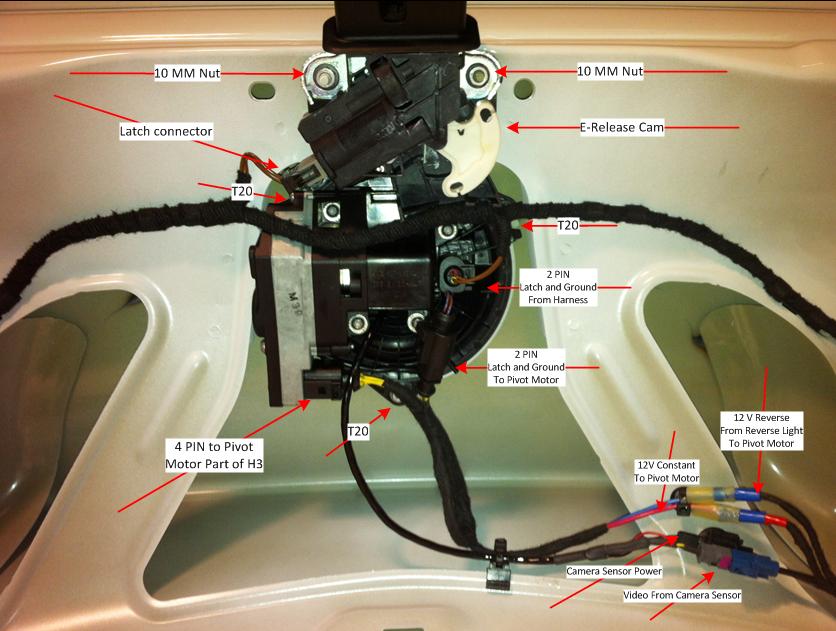
15 4- Remove existing badge and install RVC Remove the two pin plug from the trunk harness to the badge. Push the little clip down and give it a slight push in while still pushing the clip then pull the plug out. This is where the two pin connector on H3 will plug in to send latch and ground to the Badge Pivot Motor four pin connector. Remove the 3 PIN connector from the latch assembly. Remove the two 10mm nuts holding the Latch assembly in place, remove the latch assembly and set it aside. Remove the 3 Torx bolts holding the Badge to the Trunk Lid. There is one at the top and one about 1/3 around from the bottom on each side. Remove the little black rubber plug at the bottom center of the Trunk Lid. Insert the new Drain Tube into the hole in the bottom center of the Trunk Lid. You will need to use a trim tool to coax the inside lip of the tube into the hole to make a tight seal. Holding the new RVC inside the Trunk Lid and attach the drain tube to the white barb fitting on the bottom of the RVC. You can stretch it a little to mate it well with the RVC. Now insert the RVC into the trunk lid. Be mindful of the two tabs on the RVC around the outer lip, they need to slip over the lip of the hole in the Trunk Lid and will allow the RVC to hang there with no bolts in the holes. Insert the three Torx into the RVC flange and make them snug. Reinstall the latch assembly and plug in its connector. The next page has a photo of the badge assembly mounted in the trunk lid. The 2PIN connections are depicted wrong as I had not yet had power connected to the pivot motor and you need the 12V constant to allow the latch signals through the motor to operate the latch for manual trunk opening. Since I did not do this work all in one shot I wanted to be able to open my trunk. So the picture shows the harness plugged directly into the badge. In actuality you will leave the two pin connector which is on the RVC plugged into the back of the badge and you will plug the 2PIN from the harness into your new H3 harness 2PIN female connector. 15
16 16

17 5- Install H2 Harness Remove the plastic coax connector on the CCU end cover that connector with electrical tape to protect it. Fish some sort of stiff wire through the pivot tube from top to bottom, to use it to pull your harness through. I wrapped the harness section from about 2 inches from the connectors to the RVC down to about 2 feet beyond what passes through the pivot tube, completely in cloth tape. I also used cloth tape to cover the edges of the tube at the bottom inside the trunk to prevent chaffing. Once you have the harness secured on the trunk lid, you need to figure out how much slack you will need inside the trunk to allow for smooth operation of the trunk lid. I did this by laying in the trunk and opening and closing things to check clearance and movement. Mount H2 to the harness running along the right rear wheel well and then run it down to the compartment aft of the rear well and leave it there for now. 6- Mount the CCU I used the mounting rack from my original Sirius tuner which came with the car. Three bolts and it is free. I then Velcro strap and zip tied the CCU to that rack and mounted it back in place. If you don t have this rack you are up to your own devices to figure a mounting maybe get the rack from VW? Area for mounting shown below. 17
18 7- Build and Install Harness H3 The next page will cover basic soldering for the construction of the harness depicted above. 18


19 Building this harness using the repair wire ends for the appropriate connector and solder the 16g extensions by twisting the ends into each other and then soldering them together. Set your lengths by laying things up next to the badge where you will want things. Use the photo on page 16 as a guide. Then heat shrink them to insulate 19
20 Pay attention to the orientation of the pins as you set them into the connectors and then lock them in by sliding the magenta locks inside each connector. If you orient the pins wrong, 90 degrees off, they will not mate. Just work slowly and inspect how the connectors go together. Squirt some clear silicone fish tank sealant into the back of all the plugs on H3 once you have the pins set and locked. This will complete the weather sealing. For the 12V Reverse signal I used crimp on spade connector from Radio Shack. o Cut the wire to PIN 2 on the reverse lamp about 1.5 inches from the plug. o Install one side of the spade connector on the plug side wire. o Twist the wire feeding 12V reverse to H3 together with the harness side of the wire to the reverse lamp and crimp the other side of the spade connector to it and mate the spade connectors. o Run the wire from the reverse lamp along the existing loom and wrap it in with the cloth tape. o Use a crimp on bullet connector to make the connection to the H3 harness as depicted in the previous picture of the trunk lid. For the 12V constant feed from the H2 harness use a crimp on bullet connector to make the connection to the H3 harness as also depicted in the photo on page 16. Plug everything in and you are done with the trunk lid wiring. Leave all the trim off for now until you test everything good. 20


21 Head Unit Removal 1- Remove the RNS from the dash Place a heavy towel or blanket across the gear shifter and console to prevent marring. Place painters or masking tape over the climate control panel with painters tape to also prevent any marring. Using the trim tool remove the trim surrounding the RNS Take care when disconnecting the passenger airbag light connector as it likes to try and retract itself back into the dash. 21


22 Remove the four Torx holding the RNS in place Gently pull the RNS out of the dash. Do not push on the screen of push or pull on any knobs or buttons. Remove the large main plug on the top rear corner by releasing the lever and pulling it out. It will require some force and click when released. Release the coax connectors for the radio antennas and the nav antenna 22

23 Here is a photo of the antenna connectors and the RNS end of the H1 harness. The two white ones are the radio antennas and the blue is for the navigation. Set the RNS aside in a safe place. 23
24 H1 Harness Install 1- Trim Removal Start with the front door sill trim. Just grab it and pull it up along its length. There are several metal clips holding it in. Remove the outboard kick panel trim. Two clips hold it in place. Work the lower B pillar trim loose. You need only to pop the lower sill trim loose, depicted in yellow highlight. It is a VERY long piece. Mind the seatbelt. Remove the last piece of trim which runs up the rear of the rear door well. Remove the Torx holding the black metal plate underneath the rear door sill trim to gain access to the wiring channel. 24
25 2- Install H1 Harness Extend the ground wire on the RNS end of H1 in the same way you made the splices for H3. Make this long as it will need to run from the back of the RNS into the inboard kick panel area of the front passenger seat where the ground mounting bolt lives. The ground wire will be common with PIN 44 on the CCU connector end of H1. On my harness it was black but check with a meter to be sure! You should have made an extension for the single 12V constant which you will extend to the fuse panel. I put a crimp on bullet connector on one end and on the repair wire end for the addition of the new fuse circuit later. Starting just forward of the B pillar feed the CCU end of H1 into the channel in the sill working towards the rear and the CCU. Feed H1 past the B pillar and into the sill of the right rear door. Follow the existing harness under the black metal plate. In the sill of the right rear door you should see the existing wiring harnesses running into a plastic channel. On the outboard of that channel you should see a channel to lay in the H1 wires where they fit like they were meant to. Run H1 along the existing harness you will see running up under the airbag and over the right rear wheel well towards the rear. You should be able to see empty clips along the harness which is where H1 should be clipped into. You can also just run H1 along the existing harness and use the cloth tape to secure it. Either way, take care in where you lay H1 to prevent any chaffing. If you secure it tightly with the clips or with tape you should be fine. Once you reach the CCU plug it in and mate the single 12V constant wire connection between H1 and H2. Mate the 2 PIN connector feeding 12V and Ground to the camera between H1 and H2. Remove the two small metal finger nuts holding the foam cover under the glove box and carefully remove the foam. Remove the one Torx securing the inboard kick panel next to the passenger seat and then briskly pull it down then forward to remove it. Feed the rest of H1 along the right front door in the sill channel along the existing harness and then up under the glove box in the channel just behind the top edge of the carpet. 25
26 Use a stiff wire to fish from the hole in the dash for the RNS down into the inboard kick panel. Attach the RNS end of H1to the wire and pull it up through the hole keeping the ground wire separate and not pulling it through since you will need to attach it to the ground connecting at the bottom. Use a crimp on ring tongue about 5mm diameter for the end of the ground wire for H1. Remove the ground nut in the now open inboard kick panel and attach the ground wire to the post and reinstall the nut. Reinstall all of the kick panel and sill trim pieces. Reinstall the foam panel under the dash. Reinstall the luggage compartment trim. Reinstall the rear side air bag. Ground yourself on the door striker again by touching it BEFORE you plug in the air bag connector. Reinstall the rear seat. 26

27 RNS Wiring 1- Splice H1 into the RNS There are three wires we will be splicing into the RNS harness on the Main Plug 1. 12V Constant from RNS main connector section 2 PIN CAN bus high from RNS main connector section 2 PIN 9 3. CAN bus low from RNS main connector section 2 PIN 10 The rear of the RNS The Main Plug Detail 27
28 Bear in mind the preceding diagrams are of the rear of the RNS so when you have the plug off it will be slightly reversed. The pins are marked on the plug when you pull the sub-plugs out of the plug chassis. Keep track of where each goes as you will need to remove them all to have room to work. Refer back to the previous diagrams. Pin 15 on my unit was easy to identify as it was a red wire with yellow stripe and it was a larger gauge than the others. YOU STILL HAVE THE BATTERY DISCONNECTED RIGHT? Cut the wire on PIN 15 (marked with the RED/YELLOW box) about 2 inches from the plug and strip both ends about a quarter inch. For this next step you will want to use the larger crimp on disconnects gauge since the power wire is a larger gauge than the CAN bus connections. Give the stripped end a nice twist and crimp one half of a connector to the wire still connected to the plug and give the connector a hard tug to be sure it is solid. Twist in the power lead from the H1 which should be common with PIN 43 on the CCU end of harness H1. Crimp on the other half of a spade connector to these two wires and give the connector a hard tug to be sure it is solid. Plug the two spade connectors together and the power lead for the CCU and camera sensor is now done. Cut the wire connected to PIN 9 (marked with the orange box) about two inches from the plug and strip both ends about a quarter inch. Give the stripped end a nice twist and crimp one half of a connector to the wire still connected to the plug and give the connector a hard tug to be sure it is solid. Give the stripped end a nice twist and crimp one half of a connector to the CAN high wire hanging from H1 (mine was orange). This wire should be common with PIN 40 on the CCU end of H1. Give the spade connector a hard tug to be sure it is solid. Give the other stripped end of the wire from PIN 9 a nice twist and crimp one half of a connector to the wire still connected to the plug and give the spade connector a hard tug to be sure it is solid. Plug the spade connectors together. Cut the wire connected to PIN 10 (marked with the blue box) about two inches from the plug and strip both ends about a quarter inch. 28
29 Give the stripped end a nice twist and crimp one half of a connector to the CAN high wire hanging from H1 (mine was brown). This wire should be common with PIN 39 on the CCU end of H1. Give the spade connector a hard tug to be sure it is solid. Give the other stripped end of the wire from PIN 10 a nice twist and crimp one half of a connector to the wire still connected to the plug and give the connector a hard tug to be sure it is solid. Plug the two spade connectors together. That is all for the splices. Put the Main Plug all back together. Remove the three Torx holding the trim panel under the driver s side dash for access. Remove the change drawer in the driver s side lower dash by opening it and then pushing the two upper stop tabs in and the allowing the drawer to rotate further down. Pull it straight out, off the hinge clips. Connect your bullet connectors for the 12V constant feed to the lead you will run to the fuse panel and fish that wire down into the driver s foot well up and over the steering column and pedal linkages. You will need to fish it up from the firewall toward the back of the fuse panel. You can do this through the hole now open from removing the change drawer. After you terminate the lead in its new fuse panel slot (I ll Cover that Next) you will need to secure the entire wire run under the dash so it does not foul in the pedal linkages or the steering linkage. 29

30 Fuse Panel Circuit Addition 1- Remove Fuse Panel and Add Circuit Remove the access panel on the end of the driver s side dash Remove the three Torx holding the fuse panel in place Once loose rotate it so you can push it into the dash and then pull it out the hole created by removing the change drawer Peel back the cloth tape at the end of the harness where it meets the back of the fuse panel to expose the wire tie holding the rear of the fuse panel casing to the harness. Carefully cut the wire tie off. 30


31 Pry open the three clips around the casing and pop the rear casing off. Take a good picture of the fuses in the fuse panel for reference because now you are going to pull out all the fuses. With a small screwdriver release the latch to the retainer and slide the magenta retainer assembly down as shown. 31

32 Now you can insert the repair wire end of your 12V constant lead to H1 into the appropriate slot. Each fuse location has a top and a bottom. The top is your supply bus and the bottom will be empty for you to insert your repair wire end to feed voltage through the fuse to the H1 harness. Pay close attention to how you insert the terminal. You want to insert it so it is running up and down when the fuse panel is reinstalled so the blade of the fuse fits in. Take time to study the fuse panel and it will all make sense. Once the repair wire terminal clicks in, slide the magenta locking assembly back up into place until it clicks and the terminal is now secure. Snap the rear casing back on the fuse panel. Put a new wire tie on the harness and lip of the casing and dress it with some cloth tape. Work the fuse panel back into the hole and through the dash and back where it belongs and tighten the Torx down. Put the fuses all back in according to your photo you took earlier and install the new 15A fuse in the circuit slot you just created. Done with that!!! Installing the new circuit sounds scary but it is pretty simple. Reinstall the under dash panel. Reconnect the battery. 32

33 VCDS Coding 1- CAN Gateway 19 Insert the ignition key to the accessory position. Plug in your VCDS cable and fire up VCDS Go into VCDS and open the CAN Gateway Controller Click on Coding Click on Long Coding Helper Press the TAB Key until you have Byte 5 selected Click the checkbox next to Bit 6 [6C] Rear View Camera to enable Close the Long Coding Helper by clicking on the X Click Do It! 33
 installed is NOT checked Close the Long Coding Helper by clicking on the X Click Do It!")
34 2- RNS (Navigation) 37 Go into VCDS and open the Navigation Controller Click on Coding Click on Long Coding Helper Press the TAB Key until you have Byte 3 selected Make sure Bit 6 Back-Up Camera Low (without Control Module) installed is NOT checked Close the Long Coding Helper by clicking on the X Click Do It! 34

35 3- Camera 6C Go into VCDS and open the Back-up Camera Controller Click on Coding Enter in the Software Coding box If you do not see anything in the WorkShop Code box, enter any 5 digit code Click Do It! Close VCDS Pull out the ignition key. Reinsert the ignition key to the accessory position and reboot the RNS. Once the RNS is awake put the car in reverse and you should see the camera image on the RNS along with you guidance lines. Button up the RNS in dash and replace the trunk lid trim and ENJOY!! 35
36 I
37 II
38 III
39 IV
40 V
Connecting the rear fog light on the A4 Jetta, while keeping the 5 Light Mod
 Connecting the rear fog light on the A4 Jetta, while keeping the 5 Light Mod DISCLAIMER: I'm human and make mistakes. If you spot one in this how to, tell me and I'll fix it This was done on my 99.5 Jetta.
ES Installation Instructions. best viewed in Acrobat Reader. This tutorial is provided as a courtesy by ECS Tuning.
 Installation Instructions This tutorial is provided as a courtesy by ECS Tuning. best viewed in Acrobat Reader Proper service and repair procedures are vital to the safe, reliable operation of all engine
Installation MKIV Headlight Housings with Fog Lamps (Procedures apply to both MKIV Jetta and Golf)
") Page 1 This tutorial is provided as a courtesy by ECS Tuning. Service Procedure Installation Proper service and repair procedures are vital to the safe, reliable operation of all motor vehicles as well
Page 1 This tutorial is provided as a courtesy by ECS Tuning. Service Procedure Installation Proper service and repair procedures are vital to the safe, reliable operation of all motor vehicles as well
Raxiom Factory GPS Rear Back-up Camera Kit (07-17 Wrangler)
") Raxiom Factory GPS Rear Back-up Camera Kit (07-17 Wrangler) Installation Time: 2.5-3Hrs Tools Required: 7mm Socket & Driver 10mm Socket 10mm Open end wrench Knife / Razor blade Zip-ties Wire Cutters Needle
Raxiom Factory GPS Rear Back-up Camera Kit (07-17 Wrangler) Installation Time: 2.5-3Hrs Tools Required: 7mm Socket & Driver 10mm Socket 10mm Open end wrench Knife / Razor blade Zip-ties Wire Cutters Needle
INSTALLATION INSTRUCTIONS
 INSTALLATION INSTRUCTIONS FUEL SURGE TANK INSTALL KIT Honda S2000 Document# 19-0063 Support: info@radiumauto.com WARNING: DO NOT SMOKE WHILE WORKING ON FUEL SYSTEMS. KEEP SPARKS AND OPEN FLAMES AWAY FROM
GM TRUCK BACKUP CAMERA INSTALLATION
 GM TRUCK 07-13 BACKUP CAMERA INSTALLATION Thank you for your purchase! These instructions are intended for the do-it-yourselfer who decides to install the camera without professional assistance. Keep in
INSTALLATION INSTRUCTIONS
 INSTALLATION INSTRUCTIONS FUEL SURGE TANK INSTALLATION KIT 1999-2006 BMW E46 COUPE Document# 19-0056 Support: info@radiumauto.com Note: This kit was designed for a standard single pump Radium Engineering
 Page 1 of 14 This install requires work on your supplemental restraint system and could cause injury or damage to your car. If you are not comfortable performing the steps detailed here then do not attempt
Installation Instructions
 Installation Instructions Jeep JK Unlimited (2007 Present) Mounting Bracket and Air Line System Kit for ARB On-Board Twin Air Compressor (CKMTA12) Made in the USA Kit Contents: 1 Bracket for ARB Compressor
Mustang One-Touch Convertible Top Module (2005+) - Installation Instructions
 - Installation Instructions") Mustang One-Touch Convertible Top Module (2005+) - Installation Instructions The below installation instructions work for the following products: Mustang One-Touch Convertible Top Module (2005+) Please
Mustang One-Touch Convertible Top Module (2005+) - Installation Instructions The below installation instructions work for the following products: Mustang One-Touch Convertible Top Module (2005+) Please
Installation Instructions
 Installation Instructions Jeep JK 2-Door (2011 Present) Mounting Bracket and Air Line System Kit for ARB On-Board Twin Air Compressor (CKMTA12) Made in the USA Kit Contents: 1 Flat Bracket 1 Formed Bracket
Retro it Steering Column
 Retro it Steering Column INSTALLATION INSTRUCTIONS for 1976-86 CJ5 & CJ7 FOR PART NUMBER S: 1520800010, 1520800020, 1520800051, 1526800010, 1526800020, 1526800051 S I NCE 1986 Instruction # 8000000010
Retrofit Steering Column
 Retrofit Steering Column INSTALLATION INSTRUCTIONS for 1970-75 Camaro FOR PART NUMBER S: 1620860010, 1620860020, 1620860051, 1626860010, 1626860020, 1626860051 S INCE 1986 www.ididitinc.com 610 S. Maumee
Installation Tips for your Remote Start system (for RS4LX>GMBP for GM vehicles)
") Installation Tips for your Remote Start system (for RS4LX>GMBP for GM vehicles) Thank you for purchasing your remote start from MyPushcart.com - an industry leader in providing remote starts to doit-yourself
Installation Tips for your Remote Start system (for RS4LX>GMBP for GM vehicles) Thank you for purchasing your remote start from MyPushcart.com - an industry leader in providing remote starts to doit-yourself
Installation Instructions Jeep CJ-7
 Retrofit Steering Column Installation Instructions 1976-86 Jeep CJ-7 For Part # s 1520800010, 152800020, 1520800051 www.ididitinc.com 610 S. Maumee St., Tecumseh, MI 49286 (517) 424-0577 (517) 424-7293
Dodge Ram 09-Current CS-DTR SERIES BACKUP CAMERA INSTALLATION
 Dodge Ram 09-Current CS-DTR SERIES BACKUP CAMERA INSTALLATION Thank you for your purchase! These instructions cannot possibly cover every option group for every model year of RAM trucks so you may find
Thank you for purchasing the Craven Speed FlexPod Complete Gauge Pod Kit For R56, R58, R59, R60 with Refresh Engines (2011+)
") Thank you for purchasing the Craven Speed FlexPod Complete Gauge Pod Kit For R56, R58, R59, R60 with Refresh Engines (2011+) Before You Start Please read instructions completely before installing. These
Thank you for purchasing the Craven Speed FlexPod Complete Gauge Pod Kit For R56, R58, R59, R60 with Refresh Engines (2011+) Before You Start Please read instructions completely before installing. These
INSTALLATION INSTRUCTIONS
 INSTALLATION INSTRUCTIONS FUEL SURGE TANK INSTALLATION KIT 1999-2006 BMW E46 COUPE Document# 19-0056 Support: info@radiumauto.com Note: This kit wasn t designed for a FST-R, but can be accomplished. 1.
FITTING OF (WESTFALIA) REMOVABLE TOWBAR ON SKODA OCTAVIA WITHOUT TOWBAR PREPARATION (04/11/16 CJ v1.0)
 REMOVABLE TOWBAR ON SKODA OCTAVIA WITHOUT TOWBAR PREPARATION (04/11/16 CJ v1.0)") FITTING OF (WESTFALIA) REMOVABLE TOWBAR ON SKODA OCTAVIA 2013+ WITHOUT TOWBAR PREPARATION (04/11/16 CJ v1.0) A. INTRO ALL STEPS COMPLETED AT YOUR OWN RISK! I AM NOT LIABLE FOR ANY LOSS OR DAMAGE! These
FITTING OF (WESTFALIA) REMOVABLE TOWBAR ON SKODA OCTAVIA 2013+ WITHOUT TOWBAR PREPARATION (04/11/16 CJ v1.0) A. INTRO ALL STEPS COMPLETED AT YOUR OWN RISK! I AM NOT LIABLE FOR ANY LOSS OR DAMAGE! These
Installation Tips for your Excalibur Remote Start (for Honda and Acura Vehicles) rev 11/28/2012
 rev 11/28/2012") Installation Tips for your Excalibur Remote Start (for Honda and Acura Vehicles) rev 11/28/2012 Thank you for purchasing your remote start from MyPushcart.com - an industry leader in providing remote starts
Installation Tips for your Excalibur Remote Start (for Honda and Acura Vehicles) rev 11/28/2012 Thank you for purchasing your remote start from MyPushcart.com - an industry leader in providing remote starts
2015 Copyright Maxspeed-Motorsports.com
 1 Porsche PCM 3.1 Backup Camera Installation Instructions. Thank you for purchasing your product at www.maxspeedmotorsports.com Before you start please understand that these installation instructions are
Installation Tips for your Remote Start/Keyless Entry (for Ford Vehicles) v3.3 Updated 1/13/2013
 v3.3 Updated 1/13/2013") Installation Tips for your Remote Start/Keyless Entry (for Ford Vehicles) v3.3 Updated 1/13/2013 Thank you for purchasing your remote start from MyPushcart.com - an industry leader in providing remote
Installation Tips for your Remote Start/Keyless Entry (for Ford Vehicles) v3.3 Updated 1/13/2013 Thank you for purchasing your remote start from MyPushcart.com - an industry leader in providing remote
Installation Tips for your Crimestopper/ProStart Remote Start system (for GM vehicles) v1.01 updated 2/27/2012
 v1.01 updated 2/27/2012") Installation Tips for your Crimestopper/ProStart Remote Start system (for GM vehicles) v1.01 updated 2/27/2012 Thank you for purchasing your remote start from MyPushcart.com - an industry leader in providing
Installation Tips for your Crimestopper/ProStart Remote Start system (for GM vehicles) v1.01 updated 2/27/2012 Thank you for purchasing your remote start from MyPushcart.com - an industry leader in providing
Nissan GTR Alpha Fuel System
 Nissan GTR Alpha Fuel System Instructions V5 The goal of AMS is to provide the highest quality, best performing products available. By utilizing research and development, and rigorous testing programs
OEM Cruise Control Installation in GMC/Chevy NBS trucks
 OEM Cruise Control Installation in 99-02 GMC/Chevy NBS trucks May 2008 ~ Rampage_Rick Having just installed factory cruise control in my 00 Sierra, I thought I d share the fun. I followed the steps outlined
INSTALLATION INSTRUCTIONS
 Rear Vision System Tailgate Emblem Camera Mirror Display 2009-Current Ford F-150 and 2010-Current Super Duty (Kit part number 1008-9527) Kit Contents: Mirror Tailgate Emblem Mount with Camera Interior
RedlineGoods Tacoma Installation Manual
 RedlineGoods 2016+ Tacoma Installation Manual AUTOMATIC SHIFT BOOT AND EBRAKE BOOT Press down on the factory shift boot collar to disconnect it from the shift knob. Unscrew shift knob Pull up on the rear
Installation Tips for your Add-on Remote Start (for GM vehicles with INTSL Install 2) v3.2 Updated 11/12/2012
 v3.2 Updated 11/12/2012") Installation Tips for your Add-on Remote Start (for GM vehicles with INTSL Install 2) v3.2 Updated 11/12/2012 Thank you for purchasing your remote start from MyPushcart.com - an industry leader in providing
Installation Tips for your Add-on Remote Start (for GM vehicles with INTSL Install 2) v3.2 Updated 11/12/2012 Thank you for purchasing your remote start from MyPushcart.com - an industry leader in providing
TIP SHEET. Installation Tips for SP-404/SP EVO-ALL + SPDT Remote Start/Alarm T1642
 TIP SHEET Installation Tips for SP-404/SP-502 + EVO-ALL + SPDT Remote Start/Alarm T1642 Nissan Armada: 2008-2012 Nissan Cube: 2009-2012 Nissan Frontier: 2008-2012 Nissan Pathfinder: 2009-2012 Nissan Quest:
Depress each tab as you pull the bezel off. The bezels are tight. L.H. shown.
 2013-2014 Ford Mustang V6 & Boss 302 Lower Valance Fog Light Kit Parts List: Quantity: Tool List: Fog light & bulb with bracket 2 Flat head & Phillips screwdriver Black bezels 2 Ratchet & Socket set OR
Installation Instructions - ECS Tuning Vent Pod Vacuum/Boost Gauge Kit
 Installation Instructions - ECS Tuning Vent Pod Vacuum/Boost Gauge Kit This tutorial is provided as a courtesy by ECS Tuning. Part Number for Audi B6 A4 (2002-2004) Proper service and repair procedures
INSTALLATION INSTRUCTIONS
 Rear Vision System Tailgate Handle Camera Mirror Display 2004-2014 Ford F-150 and 2008-2015 Ford Super Duty (Kit part numbers 9002-9521) Kit Contents: Mirror Tailgate Handle with camera and harness Interior
Ford Mustang V6 OEM-Style Fog Light Kit Parts List: Quantity: Tool List:
 2015-2017 Ford Mustang V6 OEM-Style Fog Light Kit Parts List: Quantity: Tool List: LED Foglights/ Bezels 2 Flat head & Phillips screwdriver (if you ordered part#3600) Ratchet & Socket set OR Wiring harness
Installation Tips Crimestopper/ProStart Remote Start system + PLJX + DLRM + SPDT (for GM vehicles) T0760 v1.1 updated 2/5/14
 T0760 v1.1 updated 2/5/14") Installation Tips Crimestopper/ProStart Remote Start system + PLJX + DLRM + SPDT (for GM vehicles) T0760 v1.1 updated 2/5/14 Thank you for purchasing your remote start from MyPushcart.com - an industry
Installation Tips Crimestopper/ProStart Remote Start system + PLJX + DLRM + SPDT (for GM vehicles) T0760 v1.1 updated 2/5/14 Thank you for purchasing your remote start from MyPushcart.com - an industry
INSTALLATION INSTRUCTIONS
 Backup Camera Interface (Kit # 9002-7762) Please read thoroughly before starting installation and check that kit contents are complete. Items Included in the Kit: Cam T-Harness Plug & Play I/O T-Harness
Installation Instructions
 Instructions Created by an: DIY Underhood LED Lighting Kit (SKU# DIY-E-UHLK) Installation Instructions NOTICE: This Under Hood Light Kit was installed on a 2002 Toyota Tacoma. However, these instructions
Stand Alone Fog Lights Installation Instructions
 Tools Required: 1. Trim Removal tool or protected flat screwdriver 2. #2 Phillips Screwdriver 3. 10mm socket 4. 10mm wrench 5. 8mm or 5/16 socket 6. Adjustable Pliers 7. Electrical Tape WARNING!!! Disconnect
INSTALLATION INSTRUCTIONS
 9002-6513 Rear Vision System W/ Zoom Aftermarket and Factory 8.4 Touch Screen Display (Factory Display requires Chrysler/Dodge dealer to activate) 2009 2012 RAM (Part B) 2013 Current RAM (Part A) NOTE:
INSTALLATION INSTRUCTIONS
 INSTALLATION INSTRUCTIONS Document# 19-0038 2004+ Lotus Elise (Series 2) Rear Clamshell Removal Kit Safely support the vehicle. This is a two-person job. Allow 1 to 2 hours for initial disassembly. Have
Installation Tips for your Crimestopper/ProStart Remote Start system (add-on for GM vehicles) v1.02 updated 1/16/2013
 v1.02 updated 1/16/2013") Installation Tips for your Crimestopper/ProStart Remote Start system (add-on for GM vehicles) v1.02 updated 1/16/2013 Thank you for purchasing your remote start from MyPushcart.com - an industry leader
Installation Tips for your Crimestopper/ProStart Remote Start system (add-on for GM vehicles) v1.02 updated 1/16/2013 Thank you for purchasing your remote start from MyPushcart.com - an industry leader
Remote Start Kit for GM Installation RS1/3/4/7 + ADS-DL Tip Sheet
 Remote Start Kit for GM Installation RS1/3/4/7 + ADS-DL Tip Sheet rev 1.4 12/16/2013 Thank you for purchasing your remote start from MyPushcart.com - an industry leader in providing remote starts to do-it-yourself
INSTALLATION INSTRUCTIONS
 Rear Vision System Aftermarket and Factory 5.0, 8.4 and 6.1 MyGig Touch Screen Display (Factory Display requires Chrysler/Dodge dealer to activate) 2009 Current* Dodge Ram (Kit part number 1009-6503) *NOTE:
TIP SHEET T0491. Installation Tips for your Excalibur RS Passlock-sl2(4) + DLRC + SPDT
 + DLRC + SPDT") TIP SHEET T0491 Installation Tips for your Excalibur RS-360 + Passlock-sl2(4) + DLRC + SPDT For Chevrolet: Astro 1998-2005, Avalanche 2002, Blazer 1998-2005, Cavalier 2000-2003, Express Van 1998-2005,
TIP SHEET T0491 Installation Tips for your Excalibur RS-360 + Passlock-sl2(4) + DLRC + SPDT For Chevrolet: Astro 1998-2005, Avalanche 2002, Blazer 1998-2005, Cavalier 2000-2003, Express Van 1998-2005,
2005+ Mustang Trunk Lid Release and Trunk Lights Installation
 There is no warranty expressed or implied by this document, you follow these instructions at your own risk. These instructions worked for me, but your experience may vary. The final product of these instructions
Stand Alone Kit Installation Instructions
 Before installation: Stand Alone Kit Installation Instructions Read all information in this manual carefully Check the product for all components before starting the installation Remove the negative battery
GENUINE PARTS INSTALLATION INSTRUCTIONS
 GENUINE PARTS INSTALLATION INSTRUCTIONS 1. 2. 3. 4. DESCRIPTION: Accent light Kit APPLICATION: R42H (2011) PART NUMBER: 999F3 AW000 - Universal Accent Lighting Kit. KIT CONTENTS: Item QTY Description Service
Sunroof Repair. Sunroof Repair TSB. The sunroof repair kit available for the J30 is part number Y20. See images at bottom of document.
 Sunroof Repair This document is the text/images from the TSB (technical service bulletin) issued by Infiniti concerning the repair procedure for sunroof issues. Be advised that this is a LARGE, TIME-CONSUMING
Prius XM Radio Installation Instructions. Eddie Bell
 2004-2005 Prius XM Radio Installation Instructions By Eddie Bell www.metrotpn.com 1 Let me begin by saying this is an easy but time consuming job. Set aside a few hours of your time for the install. If
Conflicts: Vehicles without a sunroof Vehicles with a single sunroof
 Toyota Sienna (Dual Sunroof) 2011-10.2 Overhead Video Part Number: 00016-00110 00016-00110-17 Fit Kit 00016-00120 00016-00120-17 Fit Kit Accessory Code: ED5 Conflicts: Vehicles without a sunroof Vehicles
Peugeot 406 Coupe: Delocking your boot V.1 April 2005
 This is a first stab at a DIY guide to de-locking your 406 Coupe. It isn t a hard modification to do yourself, but you do need to be confident working on your cars electrics and removing and refitting
Please read thoroughly before starting installation and check that kit contents are complete.
 Rear Vision System Mirror Display 2013-Current Ram (Kit part number 1009-9518) Please read thoroughly before starting installation and check that kit contents are complete. Items Included in the Kit: Rear
80703 & Backside License Plate Mount for Jeep JK Wrangler (80707) & 10+ (80703)
 & 10+ (80703)") 80703 Backside Mount 80707 Backside Mount REQUIRED TOOLS 10mm SOCKET 13mm SOCKET 4mm HEX KEY WIRE CRIMPS WIRE STRIPPERS ELECTICAL TAPE SCREW DRIVER KIT CONTAINS BACKSIDE MOUNT LICENSE PLATE BRACKET WITH
80703 Backside Mount 80707 Backside Mount REQUIRED TOOLS 10mm SOCKET 13mm SOCKET 4mm HEX KEY WIRE CRIMPS WIRE STRIPPERS ELECTICAL TAPE SCREW DRIVER KIT CONTAINS BACKSIDE MOUNT LICENSE PLATE BRACKET WITH
Retro it Steering Column
 Retro it Steering Column INSTALLATION INSTRUCTIONS for 1970-74 Cuda/Challenger FOR PART NUMBER S: 1620810010, 1620810020, 1620810051, 1620820010, 1620820020, 1620820051 S I NCE 1986 Instruction # 8000000005
Retrofit Steering Column
 Retrofit Steering Column Installation Instructions for 1970-75 Camaro For Part # s: 1620860010, 1620860020, 1620860051, 1620869910, 1620869920, 1620869951, 1625860010, 1625860020, 1625860051, 1625869910,
INSTALLATION INSTRUCTIONS
 Rear Vision System Tailgate Emblem Camera Aftermarket Display 2009-Current Ford F-150 and 2010-Current Super Duty (Kit part number 1008-6509) Kit Contents: Tailgate Emblem Mount with Camera Chassis Harness
INSTALLATION INSTRUCTIONS
 OEM Recessed Lip Camera with Harness and Slimline Mirror (Kit part number 9002-8724) Please read thoroughly before starting installation and check that kit contents are complete. Items Included in the
vacuum/boost vent mounted ES best viewed in Acrobat Reader This tutorial is provided as a courtesy by ECS Tuning.
 vent mounted vacuum/boost ES2713030 This tutorial is provided as a courtesy by ECS Tuning. best viewed in Acrobat Reader Proper service and repair procedures are vital to the safe, reliable operation of
MKVI Jetta Fog Light Kit
 MKVI Jetta Fog Light Kit Part Number VW Jetta Fog Light Installation This tutorial is provided as a courtesy by ECS Tuning. Proper service and repair procedures are vital to the safe, reliable operation
X-Type w/ non-premium sound amplifier installation instructions
 X-Type w/ non-premium sound amplifier installation instructions 1. Pull radio from dash (see Radio Removal Instructions ) 2. Disconnect wiring harness from back of radio by pushing in tab on plug and pulling
Installation Tips for your Remote Start system (for Toyota Camry & Prius C, ) Crimestopper RS0+ EVO-ALL T3468 rev#1.
 Crimestopper RS0+ EVO-ALL T3468 rev#1.") Installation Tips for your Remote Start system (for Toyota Camry & Prius C, 2012-2014) Crimestopper RS0+ EVO-ALL T3468 rev#1.1 1/22/2015 Thank you for purchasing your remote start from MyPushcart.com -
Installation Tips for your Remote Start system (for Toyota Camry & Prius C, 2012-2014) Crimestopper RS0+ EVO-ALL T3468 rev#1.1 1/22/2015 Thank you for purchasing your remote start from MyPushcart.com -
INSTALLATION INSTRUCTIONS
 Jeep Wrangler Rear Vision Camera, 2007 Current (Kit # 9002-8838) Items Included in the Kit Camera Chassis Harness Zip lock bag with 15 Wire Ties & 3 Push Nuts These Instructions Required Tools & Supplies
Genuine Corvette Accessories Carbon Fiber Radio Surround Installation Instructions for Corvettes.
 Genuine Corvette Accessories Carbon Fiber Radio Surround Installation Instructions for 2005-2007 Corvettes. Difficulty: 3 out of 5. Time: Plan on about 1 hour. The tools used are: A small flashlight A
Ford Mustang GT-Style Fog Light Kit Parts List: Quantity: Tool List:
 2013-2014 Ford Mustang GT-Style Fog Light Kit Parts List: Quantity: Tool List: Fog light (Left& Right) 2 Flat head & Phillips screwdriver Upper grille with surround 1 Ratchet & Socket set OR Lower grille
Thank you for purchasing the Craven Speed FlexPod Complete Gauge Pod Kit
 Thank you for purchasing the Craven Speed FlexPod Complete Gauge Pod Kit Before You Start Please read instructions completely before installing. These instructions contain the information required to install
Installation Instructions for Chevrolet Colorado, GMC Canyon, LT, Z71, With Factory Fog Lights
 Installation Instructions for 2015-2018 Chevrolet Colorado, GMC Canyon, LT, Z71, With Factory Fog Lights This kit is designed to allow use of your factory fog light operation along with an addition auxiliary
BX8848 Installation Instructions 4 Diode Wiring Kit For Motorhomes With Red Tail Lights
 For Motorhomes With Red Tail Lights WARNG: Incorrect wiring may result in blown fuses, damaged wiring, fire, or bodily injury. Blue Ox recommends installation of this kit by a trained professional. Blue
PN R CHEVY CAMARO w/reverse Two panel Sequential LED Taillight kit installation guide. Kit Contents:
 Two panel Sequential LED Taillight kit installation guide Kit Contents: 2 LED panels 4 rubber grommets 1 power wire with t-tap 1 driver side LED harness, 24 1 passenger side LED harness, 48 2 LED extension
INSTALLATION INSTRUCTIONS
 OEM Tailgate Camera/Bezel Assembly with Chassis Harness 2014-current Chevrolet Silverado and GMC Sierra (Kit part number 9002-1005) Kit Contents: Chassis Harness 1 bubble bag containing: Tailgate Handle
Installation Tips for your Remote Start/Keyless Entry (for Mazda Vehicles) v3.1 Updated 9/22/2012
 v3.1 Updated 9/22/2012") Installation Tips for your Remote Start/Keyless Entry (for Mazda Vehicles) v3.1 Updated 9/22/2012 Thank you for purchasing your remote start from MyPushcart.com - an industry leader in providing remote
Installation Tips for your Remote Start/Keyless Entry (for Mazda Vehicles) v3.1 Updated 9/22/2012 Thank you for purchasing your remote start from MyPushcart.com - an industry leader in providing remote
GENUINE PARTS INSTALLATION INSTRUCTIONS
 GENUINE PARTS INSTALLATION INSTRUCTIONS 1. 2. 3. 4. DESCRIPTION: APPLICATION: PART NUMBER: KIT CONTENTS: Accent light Kit Versa Note 999F3 4Z000 - Accent Lighting Kit. 999Q9 AY000 - Accessory Service Connector
Installation Tips For Crimestopper RS7 + Passlock-sl2(4) + DLRM + SPDT
 + DLRM + SPDT") TIP SHEET T3628 Installation Tips For Crimestopper RS7 + Passlock-sl2(4) + DLRM + SPDT For Chevrolet: Astro 1998-2005, Avalanche 2002, Blazer 1998-2005, Cavalier 2000-2003, Express Van 1998-2005, S10 Pickup
TIP SHEET T3628 Installation Tips For Crimestopper RS7 + Passlock-sl2(4) + DLRM + SPDT For Chevrolet: Astro 1998-2005, Avalanche 2002, Blazer 1998-2005, Cavalier 2000-2003, Express Van 1998-2005, S10 Pickup
Installation Instructions for the Plug & Play Chrysler/Dodge/Jeep Remote Start Package w/mux T5
 v1.01 12/14/2102 Installation Instructions for the Plug & Play Chrysler/Dodge/Jeep Remote Start Package w/mux T5 Review the remote start installation manual for safety instructions! Overview Your kit consists
Installation Tips for your Remote Start/Keyless Entry (for Honda/Acura Vehicles) [EVO-ALL] v1.02 updated 9/13/2013
![Installation Tips for your Remote Start/Keyless Entry (for Honda/Acura Vehicles) [EVO-ALL] v1.02 updated 9/13/2013](/thumbs/87/96035180.jpg "Installation Tips for your Remote Start/Keyless Entry (for Honda/Acura Vehicles) [EVO-ALL] v1.02 updated 9/13/2013") Installation Tips for your Remote Start/Keyless Entry (for Honda/Acura Vehicles) [EVO-ALL] v1.02 updated 9/13/2013 Thank you for purchasing your remote start from MyPushcart.com - an industry leader in
Installation Tips for your Remote Start/Keyless Entry (for Honda/Acura Vehicles) [EVO-ALL] v1.02 updated 9/13/2013 Thank you for purchasing your remote start from MyPushcart.com - an industry leader in
LGT-306L / LB Club Car Precedent LED Light Bar Bumper Kit Installation Instructions
 LGT-306L / LB Club Car Precedent LED Light Bar Bumper Kit Installation Instructions Caution: Please read through the instructions carefully. Before starting this project, remove the system s positive and
We will be upgrading from the factory, paper-cone disgrace to an Infinity Kappa 62.9i:
 In order to fully round out your stereo upgrade, the factory rear speakers must go. This is another easy job to tackle, but the fitment of the package tray and being hunched over in the rear glass area
Jeep Wrangler Rear Vision Camera, 2007 Current (Kit # )
") Jeep Wrangler Rear Vision Camera, 2007 Current (Kit # 9002-8837) Items Included in the Kit Required Tools & Supplies Camera Chassis Harness Zip lock bag with 15 Wire Ties & 3 Push Nuts Program Module 22--pin
Jeep Wrangler Rear Vision Camera, 2007 Current (Kit # 9002-8837) Items Included in the Kit Required Tools & Supplies Camera Chassis Harness Zip lock bag with 15 Wire Ties & 3 Push Nuts Program Module 22--pin
C15C C15C. Page 1 of 20
 2 x Lid Front Hinge 1135 8 x M8 Bolt 8 x M8 Washer (3mm Thick) 4 x M6 Large washers 4 x M6 Spring washers 4 x M6 x 40mm Bolts 6 x M6 20mm Bolts 6 x M6 Washers 20 x Screws 2 x Lid mount gas strut bracket
Read the entire installation manual. There are several safety tips there that you need to know before you start
 Installation Tips for RS4 + INTSL (2) TIP SHEET T0749 Buick Century: 2000-2005 Buick LeSabre: 2000-2005 Buick Park Avenue: 1999-2005 Buick Ranier: 2004-2007 Cadillac Escalade: 2003-2007 Chevrolet Avalanche:
Procharger Stage II Intercooled Supercharger System (11-14 GT)
") Procharger Stage II Intercooled Supercharger System (11-14 GT) Installation Time: Approximately one day. Installed on 2012 Mustang GT 5.0/Manual Required Tools 3/8 Socket Set (Standard and Metric) 1/2
Procharger Stage II Intercooled Supercharger System (11-14 GT) Installation Time: Approximately one day. Installed on 2012 Mustang GT 5.0/Manual Required Tools 3/8 Socket Set (Standard and Metric) 1/2
Classic Light Bar Mustang
 Classic Light Bar 2005-2012 Mustang Note: Read installation instructions before starting. Component List: 1 Light Bar Part #110000 1 Driver Side Bracket w/set Screw Part #115003 1 Passenger Side Bracket
GENUINE PARTS INSTALLATION INSTRUCTIONS
 GENUINE PARTS INSTALLATION INSTRUCTIONS 1. 2. 3. 4. DESCRIPTION: Illuminated Kick Plate Kit APPLICATION: Murano PART NUMBER: 999G6 C2000, 999G6 C2100, 999G6 C2200 999Q9 AY001 - Accessory Service Connector
Installation Tips for your Remote Start w/ Keyless Entry (Toyota Vehicles) v3.2 Updated 3/14/13
 v3.2 Updated 3/14/13") Installation Tips for your Remote Start w/ Keyless Entry (Toyota Vehicles) v3.2 Updated 3/14/13 Thank you for purchasing your remote start from MyPushcart.com an industry leader in providing remote starts
Installation Tips for your Remote Start w/ Keyless Entry (Toyota Vehicles) v3.2 Updated 3/14/13 Thank you for purchasing your remote start from MyPushcart.com an industry leader in providing remote starts
#TL T EA888 GEN 3 FUELING SYSTEM/ INSTALLATION INSTRUCTIONS
 #TL100069 2.0T EA888 GEN 3 FUELING SYSTEM/ INSTALLATION INSTRUCTIONS Notes: These instructions were written for a North American specification MkVII GTI. Other models, like the Golf R, are similar. When
Jeep Wrangler Rear Vision Camera, 2007 Current (Kit # )
") Items Included in the Kit Camera Chassis Harness Zip lock bag with 15 Wire Ties & 3 Push Nuts These Instructions 22--pin white connector w/ video RCA (for factory display radio) Jeep Wrangler Rear Vision
Items Included in the Kit Camera Chassis Harness Zip lock bag with 15 Wire Ties & 3 Push Nuts These Instructions 22--pin white connector w/ video RCA (for factory display radio) Jeep Wrangler Rear Vision
How to Install a 997, Boxster, & Cayman Radio
 How to Install a 997, Boxster, & Cayman Radio Step-by-step instructions for a 997.1, Boxster, & Cayman Radio Installation. *Credit to CAI- Store.com for this Guide* Written By: Danielle 2017 guides.drivediy.com
Deuce/Ace Installation Instructions
 HARDWARE KIT: Upper Mounting Plate: 2-7/16" (11mm) X 3.5" bolts 2-7/16" flange nuts 2-2" spacers 2-7/16" trim cap mounting washers 2 - plastic trim caps TOOLS NEEDED: safety glasses wrenches 16mm or 5/8"
INSTALLATION INSTRUCTIONS
 Rear Vision System Liftgate Emblem Camera Mirror Display 2009-2012 Ford Flex (Kit part number 1008-9527) Kit Contents: Mirror Liftgate Emblem Mount with Camera Interior (shorter) Harness Chassis (longer)
Installation Tips for your GMDLBP + Excalibur Remote Start system (for GM vehicles) v1.01 updated 10/09/13
 v1.01 updated 10/09/13") Installation Tips for your GMDLBP + Excalibur Remote Start system (for GM vehicles) v1.01 updated 10/09/13 Thank you for purchasing your remote start from MyPushcart.com - an industry leader in providing
Installation Tips for your GMDLBP + Excalibur Remote Start system (for GM vehicles) v1.01 updated 10/09/13 Thank you for purchasing your remote start from MyPushcart.com - an industry leader in providing
TOYOTA VENZA HANDS FREE BLU LOGIC Preparation
 TOYOTA VENZA 2009- HANDS FREE BLU LOGIC Preparation Part #: PT923-00111 Conflicts: JBL Audio NOTE: Part number of this accessory may not be the same as the part number shown. Kit Contents: For kits manufactured
Backside License Plate Mount for Jeep JK Wrangler
 REQUIRED TOOLS 10mm SOCKET 13mm SOCKET 4mm HEX KEY WIRE CRIMPS WIRE STRIPPERS ELECTICAL TAPE SCREW DRIVER KIT CONTAINS BACKSIDE MOUNT LICENSE PLATE BRACKET WITH LEDS PLASTIC PASS-THROUGH GROMMET STAINLESS
Installation of Auto Meter Cobalt Boost/Vacuum Gauge:
 Installation of Auto Meter Cobalt Boost/Vacuum Gauge: Fitment: All 79-14 models. This installation was completed on a 2004 Mustang GT, and should be identical for all 1999-2004 model Mustangs. Time needed:
CHEVY CAMARO Four panel Sequential LED Taillight kit installation guide
 1978-81 CHEVY CAMARO Four panel Sequential LED Taillight kit installation guide Kit Contents: 4 LED panels 1 power wire with t-tap 2 driver side LED harnesses, 24 2 passenger side LED harnesses, 48 4 LED
Installation Instructions - ECS Tuning Vent Pod Vacuum/Boost Gauge Kit
 Installation Instructions - ECS Tuning Vent Pod Vacuum/Boost Gauge Kit This tutorial is provided as a courtesy by ECS Tuning. Part Number for (2005-2008) Proper service and repair procedures are vital
Installation Instructions for the Plug & Play Remote Start Package (EVOCHR4)
") T6002 v1.1 02/2013 Installation Instructions for the Plug & Play Remote Start Package (EVOCHR4) For CHRYSLER Town & Country 2008-2012 Review the remote start installation manual for safety instructions!
T6002 v1.1 02/2013 Installation Instructions for the Plug & Play Remote Start Package (EVOCHR4) For CHRYSLER Town & Country 2008-2012 Review the remote start installation manual for safety instructions!
Rear Vision System Tailgate Emblem Camera Aftermarket Display 2009-Current Ford F-150 and 2010-Current Super Duty (Kit part number )
") Rear Vision System Tailgate Emblem Camera Aftermarket Display 2009-Current Ford F-150 and 2010-Current Super Duty (Kit part number 1008-6509) Kit Contents: Tailgate Emblem Mount with Camera Chassis Harness
Rear Vision System Tailgate Emblem Camera Aftermarket Display 2009-Current Ford F-150 and 2010-Current Super Duty (Kit part number 1008-6509) Kit Contents: Tailgate Emblem Mount with Camera Chassis Harness
Gentex by VOXX Corporation Installation Instructions
 KIT CONTENTS: Item Qty Part Number Description 1 1: ADVGEN20A 7 Pin Auto-Dimming Mirror with Compass and Temperature 2 1 Gentex by VOXX Corporation Installation Instructions Contact VOXX Customer Service
Remove black panel shown. Save 6 retaining pins for re-install later. Pry up on center part of pin first. Then pry out entire retaining pin.
 2005-2009 Ford Mustang V6 Fog Light Wiring Kit Parts List: Quantity: Tools Required: Wiring harness 1 Flat head screwdriver Supplemental wire leads 2 Ratchet & Socket set OR Wire tap red 2 Adjustable Wrench
VTCM Installation Manual Table of Contents
 VTCM Installation Manual Table of Contents 1. Introduction:... 2 2. Disclaimer:... 2 3. Software / Drivers:... 2 a. Plugging in the controller:... 2 b. Install 4.0.NET Frame work:... 3 c. Install COM port
Trail Rocker Installation Instructions
 Trail Rocker Installation Instructions Manual #90580 For Installing Painless Part Numbers: 57000 and 57001 Painless Performance Products recommends you, the installer, read this installation manual from
Trail Rocker Installation Instructions
 Trail Rocker Installation Instructions Manual #90581 For Installing Painless Part Numbers: 57002 Painless Performance Products recommends you, the installer, read this installation manual from front to