Rotary Actuator. New RoHS. Compact auto switches are mountable. Weight is reduced by up to 14 %. Mounting interchangeable with the current model
|
|
|
- Ethel Ramsey
- 6 years ago
- Views:
Transcription


![CRA1 [kg] [kg]](/docs-images/79/79985344/images/1-20.jpg "Reduction rate")
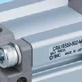

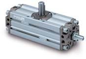
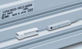
1 Rotary Actuator Ø 30, Ø 50, Ø 63, Ø 80, Ø 100 New RoHS Compact auto switches are mountable. (D-M9 ) Width reduced by up to 14 mm Space saving by changing the auto switch rail mounting to groove mounting. Current model Mountable on 2 surfaces. Compact auto switch Auto switch can be mounted from the front. Auto switch can be mounted from the front at any position on the mounting groove. Auto switch can be mounted after installation or when installation condition is changed. Mounting ng bracket Weight is reduced by up to 14 %. Lightweight body by changing the body and the cover shape. CRA1 [kg] Current model [kg] Reduction rate [%] Mounting interchangeable with the current model Series CRA1 Standard type : 30, 50, 63, 80, 100 Rotating 30 90, 180 angle 50 to , 180, 100, 190 Angle adjustable type : 50, 63, 80, 100 Rotating 50 to 100 angle 90, 180, 100, 190 CAT.EUS20-232C-UK


 Replacement")
 Tube gasket")


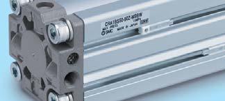
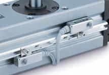
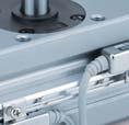
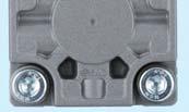
2 Rotary Actuator Series CRA1 Ø 30, Ø 50, Ø 63, Ø 80, Ø 100 Standard type Cushion seal is replaceable. Cushion seal has been made replaceable. (Not possible for current model. Cushion seal only) Replacement parts Slider Piston seal Cushion seal (New) Tube gasket Spring pin Interchangeable with current model Exterior dimension, shaft diameter, and mounting dimension are interchangeable with current model. Rotating angle to 100 Compact auto switches are mountable. Solid state auto switch D-M9 D-M9 W Reed auto switch D-A9 Easy adjustment of cushion valve Cushion valve shape is changed so it can be adjusted using a hexagon wrench only. No protrusion from the body. Retaining ring is used to prevent drop-out. Mountable on 2 surfaces. Auto switches can be mounted in two rows. 30 Auto switch Port, cushion valve and auto switch are on the same surface. Easy to handle. Cushion valve cannot be mounted on the air-hydro type. With cushion valve retaining ring Auto switches can be mounted in two rows. 50 to 100 Auto switches can be mounted in two rows. Auto switch 1 Port 30


 Bottom side Shaft side Port side Back side Angle adjustable type Angle can be adjusted to a desired level in a range of up to 90.")
3 Rotary Actuator Series CRA1 Ø 30, Ø 50, Ø 63, Ø 80, Ø 100 Many variations of shaft type Single shaft: CRA1BS Double shaft: CRA1BW Current model Standard : 2 types Semi-standard : 6 types Series CRA1 Standard: 8 types Shaft type can be selected to suit the specification. Part number is assigned for shaft types <single round shaft, double shaft (round shaft, with four chamfers), double round shaft>. Single shaft with four chamfers: CRA1BX Double shaft with key: CRA1BY Double shaft with four chamfers: CRA1BZ Single round shaft: CRA1BT Double shaft (round shaft, with four chamfers): CRA1BJ Double round shaft: CRA1BK Single round shaft, double shaft (round shaft, with four chamfers), double round shaft are made to order. Mounting suitable for operating conditions is possible. Foot bracket can be mounted at a desired position. (Foot bracket is included in the rotary actuator at shipment.) Bottom side Shaft side Port side Back side Angle adjustable type Angle can be adjusted to a desired level in a range of up to 90. Angle can be adjusted to an appropriate level suitable for applications. A port Adjusting direction B port Adjusting direction Rotation range of keyway 90 Rotation range of keyway 180 2

4 Rotary Actuator Series CRA1 Ø 30, Ø 50, Ø 63, Ø 80, Ø 100 Standard type Angle adjustable type Series Variations Type Pneumatic Air-hydro Rotating angle Single shaft S Double shaft W Single shaft with four chamfers X Standard Shaft type Double shaft with key Y Double shaft with four chamfers Z Single round shaft T Cushion Variations Mounting bracket Pattern Double shaft (round shaft, with four chamfers) J Double round shaft K None Air cushion With auto switch Angle adjustable type Clean series Note) 11- Flange F Foot L Shaft type pattern Rotation range Made to Order Port location Stainless steel shaft/bolt/parallel key -X 6 Operating temperature Heat resistant 100 C -X 7 Both sides angle adjustable -X10 One side angle adjustable, One side with cushion -X11 Fluororubber seal -X16 3
5 CONTENTS Rotary Actuator Series CRA1 Rotary Actuator Series CRA1 How to Order Page 5 Specifications Page 6 Dimensions Page 7 Construction Page 13 Rotary Actuator: Angle Adjustable Type Series CRA1 U How to Order Page 15 Specifications Page 16 Dimensions Page 17 Construction Page 18 Auto Switch Mounting Page 19 Simple Specials/Made to Order Simple specials Shaft pattern sequencing 1 -XA1 to -XA24 Page 23 Shaft pattern sequencing 2 -XA33 to -XA59 Page 27 Made to Order How to Order Page 32 qreversed shaft -XC7 Page 33 wchange of rotation range -XC8 to -XC11 Page 33 echanged to fluorine grease -XC30 Page 33 rchange of rotation range and shaft rotation direction -XC31 to XC36 Page 34 tchange of rotation range and angle adjusting direction -XC37 to XC42 Page 35 ychange of rotation range and angle adjusting direction -XC43 to XC46 Page 36 uchange of rotation range and angle adjusting direction ( is equipped on the left.) -XC47 to XC52 Page 37 ichange of rotation range and angle adjusting direction ( is equipped on the left.) -XC53 to XC58 Page 38 ochange of port location (Mounting location of the cover is changed.) -XC59 to XC61 Page 39!0One side air-hydro, One side air -XC63, -XC64 Page 39!1Stainless steel shaft/bolt/parallel key -X6 Page 40!2Heat resistant -X7 Page 40!3Both sides angle adjustable -X10 Page 40!4One side angle adjustable, One side with cushion -X11 Page 41!5Fluororubber seal -X16 Page 41 Made to Order/-X6 to -X16 Page 42 Made to Order Simple Specials Auto Switch Mounting CRA1 U CRA1 Specific Product Precautions Page 43 4
6 Rotary Actuator Series CRA1 RoHS Rack & Pinion Type/: 30, 50, 63, 80, 100 How to Order With auto switch CRA1 B S Z CDRA1 B S Z M9BW L Built-in magnet B Note 1, 2) Foot F Note 3) Mounting Basic type type Flange type Note 1) For foot bracket and part number, refer to page 6. Note 2) Foot bracket is included in the same package, (but not assembled). Note 3) Except size 30. Shaft type S Single shaft W Double shaft X Single shaft with four chamfers Y Double shaft with key Z Double shaft with four chamfers T Single round shaft J Double shaft (round shaft, with four chamfers) K Double round shaft Note 1) Flange type is not available for T, J, K. Note 2) T, J, K are made to order Rotating angle Note) Note) 190 Note) Except size 30 Air cushion None C Note) With air cushion Note) Except air-hydro type. Port type M thread M5 Rc TF G TN NPT 1/8 1/8 1/4 3/8 TT NPTF Type Pneumatic H Note) Air-hydro Note) Except size 30. Refer to page 43 for handling precautions. Number of auto switches 2 pcs. S 1 pc. Note) Up to two auto switches are mountable. Auto switch Without auto switch (Built-in magnet) Note) For applicable auto switch model, refer to the table below. Made to Order Refer to page 6. Applicable Auto Switches /Refer to the WEB catalogue or the Auto Switch Guide for further information on auto switches. Type Solid state auto switch Reed auto switch Special function Diagnosis indication (2-color indication) Water resistant (2-color indication) Electrical entry Grommet Grommet Indicator light Wiring (Output) Load voltage Auto switch model Lead wire length [m] DC AC Perpendicular In-line 0.5 ( ) 1 (M) 3 (L) 5 (Z) Pre-wired connector Applicable load 3-wire (NPN) M9NV M9N 5 V, 12 V IC circuit 3-wire (PNP) M9PV M9P 2-wire 12 V M9BV M9B 3-wire (NPN) M9NWV M9NW 5 V, 12 V IC circuit Yes 3-wire (PNP) 24 V M9PWV M9PW 2-wire 12 V M9BWV M9BW 3-wire (NPN) M9NAV 5 V, 12 V 1 M9NA 1 IC circuit 3-wire (PNP) M9PAV 1 M9PA 1 2-wire 12 V M9BAV 1 M9BA 1 Yes 3-wire (NPN equivalent) 5 V A96V A96 IC circuit 100 V A93V 2-wire 24 V 12 V 2 A93 Relay, No 100 V or less A90V A90 IC circuit PLC 1 Although it is possible to mount water resistant type auto switches, note that the rotary actuator itself is not of water resistant construction. 2 1 m type lead wire is only applicable to D-A93. Lead wire length symbols: 0.5 m (Example) M9NW 1 m M (Example) M9NWM 3 m L (Example) M9NWL 5 m Z (Example) M9NWZ Auto switches marked with are produced upon receipt of order. Auto switches are shipped together, (but not assembled). 5 Relay, PLC Refer to the WEB catalogue or the Auto Switch Guide for detailed solid state auto switches with pre-wired connectors.
7 Rotary Actuator Rack & Pinion Type Series CRA1 Angle adjustment range 3 Flange type Made to Order (For details, refer to pages 22 to 42.) Description Applicable shaft type -XA1 to -XA24 Shaft pattern sequencing! S, W, Y -XA33 to -XA59 Shaft pattern sequencing@ X, Z, T, J, K -XC7 Reversed shaft S, W, X, T, J -XC8 to -XC11 Change of rotation range S, W, Y -XC30 Changed to fl uorine S, W, X, Y, grease Z, T, J, K -XC31 to -XC36 A port Angle adjustment range 3 Change of rotation range and shaft rotation direction -XC59 to -XC61 Change of port direction -XC63, -XC64 -X6 -X7 Basic type One side air-hydro, One side air Stainless steel shaft/ bolt, etc. Heat resistant (100 C) -X16 Fluororubber seal A port B port Key B port Key Rotation range of keyway Rotation range of keyway 190 Foot type Angle adjustment range 3 Rotation range of keyway Rotation range of keyway 90 S, W, Y S, W, X, Y, Z, T, J, K S, W, X, Y, Z, T, J, K S, W, X, Y, Z, T, J, K S, W, X, Y, Z, T, J, K S, W, X, Y, Z, T, J, K X7: Not available for the built-in magnet type Rotation Range of Keyway The shaft rotates clockwise when the pressure is applied from the A port while it rotates counterclockwise when the pressure is applied from the B port. : 30 : 50 to Rotation range of keyway 100 Angle adjustment range 3 Rotation range of keyway 180 Specifications Type Pneumatic Air-hydro Fluid Air (Non-lube) Turbine oil Max. operating pressure 1.0 MPa Min. operating pressure 0.1 MPa Ambient and fluid temperature 0 to 60 C (No freezing) Cushion Not attached, Air cushion None Backlash None Within 1 Tolerance in rotating angle 0 to +4 Since the CRA1 30 has a stopper installed, there is no backlash produced under pressure. Effective Torque [N m] Operating pressure [MPa] Allowable Kinetic Energy/Adjustable Range of Rotation Time Safe in Operation Allowable kinetic energy [J] Adjustable range of rotation Without air cushion With air cushion time safe in operation [s/90 ] to to 2 Cushion angle to to to 5 Allowable kinetic energy of the product with air cushion is the maximum absorbed energy when the cushion valve adjustment is optimised. Weight [kg] Standard weight Additional weight With auto switch Foot bracket Flange bracket With 2 auto switches Foot Bracket/Part No. Foot bracket Contents Mounting screw size included in foot bracket 30 CRA1L30-Y-1Z M5 x 0.8 x CRA1L50-Y-1Z Foot bracket : 2 pcs. M8 x 1.25 x CRA1L63-Y-1Z Mounting screw : 4 pcs. M10 x 1.5 x CRA1L80-Y-1Z Collar : 4 pcs. M12 x 1.75 x CRA1L100-Y-1Z M12 x 1.75 x does not include collars. Remove the basic type mounting screws and use the mounting screws included in the foot bracket to secure the foot bracket to the cover. Use the collar as a spacer for the cover counterbore part and secure it together with the foot. For size 30, be careful not to drop the cover when removing the basic type mounting screws. Additionally, do not mount the foot bracket with the pressure applied to the port. 6 Made to Order Simple Specials Auto Switch Mounting CRA1 U CRA1
8 Series CRA1 Dimensions/Basic Type: C RA1B : 30 Single shaft: C RA1BS Double shaft: C RA1BW ø ø 8g x Cushion valve (Width across flats 1.5) 2 x M5 x 0.8 Port size A port 5.5 B port ø 8 (g6) 98 (117)/With auto switch 84 (103)/Without auto switch ø Auto switch 28 8 x M5 x 0.8 depth 6 (Opposite side 4 locations) 9 Drawing shows the appearance for rotation of 90. Dimensions show pressurisation to B port. Drawing shows that the auto switch is mounted on the side opposite to the port side. (Dimensions with an asterisk mark (*) are not required for actuators without the auto switch.) ( ) are the dimensions for rotation of 180. Note) A parallel key is included in the same package, (but not assembled). 7
9 Rotary Actuator Rack & Pinion Type Series CRA1 Dimensions/Basic Type: C RA1B : 50/63/80/100 Single shaft: C RA1BS Double shaft: C RA1BW G ø L ø D (g6) N M UU SE SC SD F SB Ø D is the shaft dimension. Note) Other dimensions are the same as the single shaft type. D (g6) G M N UU L ø DD (h9) ø D (g6) b C A L1 K H U BC CB CA A port BB BA Auto switch 2 x Port size W S 8 x J (Opposite side 4 locations) B 2 x Cushion valve (Width across flats 3) B port BA CA BC CB BB Made to Order Simple Specials Auto Switch Mounting CRA1 U CRA1 Drawing shows the appearance for rotation of 90 and 100. Dimensions show pressurization to B port. Drawing shows the auto switch mounted on the port side. ( ) are the dimensions for rotation of 180 and 190. Port size A B C D (g6) DD (h9) 50 1/ / / F H J K M depth 8 5 Without With auto switch auto switch U W BA BB BC Note) Key dimensions CA CB S SB SC SD SE S b L1 156 (189) M depth (213.5) M depth (243) M / depth (325) Note) A parallel key is included in the same package, (but not assembled) (177) 163 (201.5) 186 (230) 245 (311)
10 Series CRA1 Dimensions/Basic Type: C RA1B : 30/50/63/80/100 Single shaft with four chamfers: C RA1BX Double shaft with key: C RA1BY Double shaft with four chamfers: C RA1BZ G ø L N 0 G 0.1 UU U H H ø L L H N M UU U N H K 0 G 0.2 ø D ø L Note) Other dimensions are the same as the single shaft type. G H N U L Note) Other dimensions are the same as the single shaft type. H K UU L Note) Other dimensions are the same as the single shaft type. D (g6) G H M N U UU L Single round shaft: C RA1BT Double shaft (round shaft, with four chamfers): C RA1BJ Double round shaft: C RA1BK ø D ø L ø D ø D N M H UU UU H H H Note) Other dimensions are the same as the single shaft type. 9 D (g6) H G 0.2 ø D Note) Other dimensions are the same as the single shaft type. D (g6) G H M N UU L Note) Other dimensions are the same as the single shaft type. D (g6) H UU
11 Rotary Actuator Rack & Pinion Type Series CRA1 Dimensions/Foot Type: C RA1L : A port Auto switch Foot bracket 138(157)/With auto switch 124(143)/Without auto switch 158(177)/With auto switch 144(163)/Without auto switch Drawing shows the appearance for rotation of 90. Dimensions show pressurisation to B port. Drawing shows that the auto switch is mounted on the side opposite to the port side. ( ) are the dimensions for rotation of 180. B port x ø 6 (Mounting hole) Made to Order Simple Specials Auto Switch Mounting CRA1 U CRA1 10
 are the dimensions for rotation of 180 and 190.")
12 Series CRA1 Dimensions/Foot Type: C RA1L : 50/63/80/100 A port B port LC LA LF LH LD LE LT Foot bracket 4 x ø LB (Mounting hole) Drawing shows the appearance for rotation of 90 and 100. Dimensions show pressurisation to B port. Drawing shows that the auto switch mounted on the port side. ( ) are the dimensions for rotation of 180 and 190. Note) Other dimensions are the same as the basic type. LA LB LC With auto switch Without auto switch LF LH LT LD LE LD LE (245) 247 (285.5) 287 (331) 347 (413) 236 (269) 275 (313.5) 329 (373) 389 (455) 200 (233) 235 (273.5) 274 (318) 333 (399) 224 (257) 263 (301.5) 316 (360) 375 (441)
13 Rotary Actuator Rack & Pinion Type Series CRA1 Dimensions/Flange Type: C RA1F : 50/63/80/100 Single shaft: C RA1FS Double shaft: C RA1FW Single shaft with four chamfers: C RA1FX F ZY FT FX ZX H U 2 x MM FY 4 x ø FD (Mounting hole) Note) Other dimensions are the same as the basic type. F H MM U FD M6 x 1.0 depth 12 M6 x 1.0 depth 12 M8 x 1.25 depth 16 M10 x 1.5 depth H N H U U UU Note) Other dimensions are the same as the single shaft type. H N U UU Double shaft with key: C RA1FY UU N N H H N U Note) Other dimensions are the same as the single shaft type. H N U Double shaft with four chamfers: C RA1FZ U UU Made to Order Simple Specials Auto Switch Mounting CRA1 U CRA1 FT FX FY ZX ZY Note) Other dimensions are the same as the single shaft type. H U UU Note) Other dimensions are the same as the single shaft type. H N U UU The dimensions of shaft key and four chamfers are the same as the basic type. For details, refer to page 9. 12
14 Series CRA1 Construction: 30 Without air With Without air cushion With auto switch!6!8!7 Component Parts No. Description Material Note 1 Body Aluminium alloy Anodised 2 Right cover Aluminium alloy Metallic coating 3 Left cover Aluminium alloy Metallic coating 4 Piston Aluminium alloy 5 Shaft Alloy steel 6 Rack Carbon steel Nitrided 7 Slider Resin 8 Bearing retainer Zinc alloy Chromated 9 Tube gasket NBR 10 Piston seal NBR 11 Bearing High carbon chrome bearing steel 12 Hexagon socket head cap screw with washer Alloy steel Zinc chromated 13 Spring pin Steel Zinc chromated 14 Parallel key Carbon steel 15 Cross-recessed pan head tapping screw Steel Zinc chromated 16 Auto switch 17 Magnet 18 Switch spacer Resin 19 Cushion ring Aluminium alloy Anodised 20 Cushion valve Steel Nickel plated 21 Cushion seal Urethane 22 O-ring NBR No. Description Material Note 23 Seal retainer Steel 24 Parallel key Carbon steel 25 Stopper Alloy steel 26 Piston holding bolt Alloy steel Zinc chromated 27 Hexagon socket head set screw Alloy steel Zinc chromated 28 Hexagon nut Steel Zinc chromated 29 O-ring NBR Replacement Parts Part no. Without air cushion With air cushion Air-hydro Note 2) 90 P P P P u, o,!0,!3 are u, are Corresponding parts included as a set. included as a set. Note 1) When ordering replacement parts, write 1 for one set of the parts per actuator. Note 2) Replacement parts for different rotation angles are set. A grease pack (10 g) is included. If an additional grease pack is needed, order with the following part number. Grease pack part number: GR-S-010 (10 g) 13
15 Rotary Actuator Rack & Pinion Type Series CRA1 Construction: 50 to 100 Without air cushion With air cushion e o i!0 q w!7 y!3 u!6!2 Component Parts No. Description Material Note 1 Body Aluminium alloy Anodised 2 Right cover Aluminium alloy Metallic coating 3 Left cover Aluminium alloy Metallic coating 4 Piston Aluminium alloy 5 Shaft Alloy steel 6 Rack Carbon steel Nitrided 7 Slider Resin 8 Bearing retainer Aluminium alloy Chromated 9 Tube gasket NBR 10 Piston seal NBR 11 Bearing High carbon chrome bearing steel 12 Hexagon socket head cap screw with washer Alloy steel Zinc chromated 13 Spring pin Steel Zinc chromated 14 Parallel key Carbon steel 15 Connecting screw Carbon steel Zinc chromated 16 Cross-recessed pan head tapping screw Steel Zinc chromated 17 Wear ring Resin 18 Auto switch 19 Magnet 20 Switch spacer Resin 21 Cushion ring Aluminium alloy Anodised 22 Cushion valve Steel Zinc chromated 23 Cushion seal Urethane 24 O-ring NBR 25 Seal retainer Steel 26 Retaining ring Steel Without air cushion With auto Replacement Parts Part no. Without air cushion With air cushion Air-hydro 50 P P P P P P P P P P P P u, o,!0,!3 are u, are u, o,!0,!3 are included as a set. included as a set. included as a set. Corresponding parts Note) When ordering replacement parts, write 1 for one set of the parts per actuator. A grease pack (10 g) is included. If an additional grease pack is needed, order with the following part number. Grease pack part number: GR-S-010 (10 g) Made to Order Simple Specials Auto Switch Mounting CRA1 U CRA1 14
16 Rotary Actuator: Angle Adjustable Type (Angle adjustment mechanism is provided as standard.) Series CRA1 U RoHS Rack & Pinion Type/: 50, 63, 80, 100 How to Order CRA1 With auto switch CDRA1 B S U50 90 Z B S U50 90 Z M9BW Built-in magnet Mounting B Basic type L Note 1, 2) Foot type F Flange type Note 1) For foot bracket and part number, refer to page 16. Note 2) Foot bracket is included in the same package, (but not assembled). Shaft type S Single shaft W Double shaft Single shaft with four X chamfers Y Double shaft with key Double shaft with four Z chamfers T Single round shaft Double shaft (round shaft, J with four chamfers) K Double round shaft Flange type is not available for T, J, K. T, J, K are made to order. Angle adjustable type Rotating angle Auto switch Without auto switch (Built-in magnet) For applicable auto switch model, refer to the table below. Number of auto switches 2 pcs. S 1 pc. Note) Up to two auto switches are mountable. Port type Rc TF G TN NPT 1/8 1/4 3/8 TT NPTF Made to Order Refer to page 16. Applicable Auto Switches /Refer to the WEB catalogue or the Auto Switch Guide for further information on auto switches. Type Solid state auto switch Reed auto switch Special function Diagnosis indication (2-color indication) Water resistant (2-color indication) Electrical entry Grommet Grommet Indicator light Wiring (Output) Load voltage Auto switch model Lead wire length [m] DC AC Perpendicular In-line 0.5 ( ) 1 (M) 3 (L) 5 (Z) Pre-wired connector Applicable load 3-wire (NPN) M9NV M9N 5 V, 12 V IC circuit 3-wire (PNP) M9PV M9P 2-wire 12 V M9BV M9B 3-wire (NPN) M9NWV M9NW 5 V, 12 V IC circuit Yes 3-wire (PNP) 24 V M9PWV M9PW 2-wire 12 V M9BWV M9BW 3-wire (NPN) M9NAV 5 V, 12 V 1 M9NA 1 IC circuit 3-wire (PNP) M9PAV 1 M9PA 1 2-wire 12 V M9BAV 1 M9BA 1 Yes 3-wire (NPN equivalent) 5 V A96V A96 IC circuit 100 V A93V 2-wire 24 V 12 V 2 A93 Relay, No 100 V or less A90V A90 IC circuit PLC 1 Although it is possible to mount water resistant type auto switches, note that the rotary actuator itself is not of water resistant construction. 2 1 m type lead wire is only applicable to D-A93. Lead wire length symbols: 0.5 m (Example) M9NW 1 m M (Example) M9NWM 3 m L (Example) M9NWL 5 m Z (Example) M9NWZ Auto switches marked with are produced upon receipt of order. Auto switches are shipped together, (but not assembled). 15 Relay, PLC Refer to the WEB catalogue or Auto Switch Guide for detailed solid state auto switches with pre-wired connectors.
17 Rotary Actuator: Angle Adjustable Type Rack & Pinion Type Series CRA1 U Specifications Made to Order (For details, refer to pages 22 to 42.) Description Applicable shaft type -XA1 to -XA24 Shaft pattern sequencing! S, W, Y -XA33 to -XA59 Shaft pattern sequencing@ X, Z, T, J, K -XC7 Reversed shaft S, W, X, T, J -XC30 Changed to fl uorine grease S, W, X, Y Z, T, J, K Change of rotation range -XC37 to -XC46 S, W, Y and angle adjusting direction Change of rotation range and angle adjusting direction -XC47 to -XC58 S, W, Y ( is equipped on the left.) S, W, X, Y -XC59 to -XC61 Change of port direction Z, T, J, K -X7 Heat resistant type (100 C) -X16 Fluororubber seal -X10 -X11 Both sides angle adjustable One side angle adjustable, One side with cushion S, W, X, Y Z, T, J, K S, W, X, Y Z, T, J, K S, W, X, Y Z, T, J, K S, W, X, Y Z, T, J, K -X7: Not available for the built-in magnet type. Type Pneumatic Fluid Air (Non-lube) Max. operating pressure 1.0 MPa Min. operating pressure 0.1 MPa Ambient and fluid temperature 0 to 60 C (No freezing) Cushion None Backlash Within 1 Angle adjustment range Max. 90 For details about the effective torque, allowable kinetic energy, and adjustable range of rotation time safe in operation, refer to page 6. Weight Standard weight Additional weight With auto switch Foot bracket Flange bracket With 2 auto switches Rotation Range of Keyway/Angle Adjustment The shaft rotates clockwise when the pressure is applied from the A port. The clockwise rotation end position is adjusted using the angle adjusting screw. Note) Take appropriate measures so that no excessive external impact or vibration is applied to the angle adjusting screw. Failure to do so may cause the angle adjusting screw to become loose or drop. A port B port Rotation range of keyway 180 Rotation range of keyway 100 Rotation range of keyway 190 [kg] Made to Order Simple Specials Auto Switch Mounting CRA1 U CRA1 Adjustment angle per rotation of angle adjusting screw Adjusting angle Foot Bracket/Part No. Foot bracket Contents Mounting screw size included in foot bracket 50 CRA1L50-Y-1Z M8 x 1.25 x CRA1L63-Y-1Z Foot bracket : 2 pcs. M10 x 1.5 x 40 Mounting screw: 4 pcs. 80 CRA1L80-Y-1Z Collar : 4 pcs. M12 x 1.75 x CRA1L100-Y-1Z M12 x 1.75 x 50 Remove the basic type mounting screws and use the mounting screws included in the foot bracket to secure the foot bracket to the cover. Use the collar as a spacer for the cover counterbore part and secure it together with the foot. 16
18 Series CRA1 U Dimensions/Basic Type: C RA1BSU : 50/63/80/100 Single shaft: C RA1BSU ø DD (h9) ø D (g6) W AU MU 8 x J (Opposite side 4 locations) F B BC K b L1 H 2 x Port size Auto switch SU (Max.) SE SC SD U A port SB C A BU (Width across flats) BB BA S B port BA BB CU (Hexagon width across flats) Drawing shows the appearance for rotation of 90 and 100. Dimensions show pressurisation to B port. Drawing shows the auto switch mounted on the port side. ( ) are the dimensions for rotation of 180 and 190. Note 1) Port size A B C D (g6) DD (h9) 50 1/ / / / F H J K M8 x 1.25 depth 8 M10 x 1.5 depth 12 M12 x 1.75 depth 13 M12 x 1.75 depth Without With auto switch auto switch U W BA BB BC S SB SC SD SE S 156 (189) 175 (213.5) 199 (243) 259 (325) (177) 163 (201.5) 186 (230) 245 (311) AU BU CU SU MU Key Note) dimensions b L M12 x M14 x M16 x M20 x Note) A parallel key is included in the same package, (but not assembled). 17 The dimensions of the shaft type W: Double shaft, X: Single shaft with four chamfers, Y: Double shaft with key, Z: Double shaft with four chamfers, T: Single round shaft, J: Double shaft round shaft, with four chamfers, K: Double round shaft, foot type, and fl ange type are the same as the standard type. For details, refer to pages 9 to 12.
19 Rotary Actuator: Angle Adjustable Type Rack & Pinion Type Series CRA1 e!0 t!1!6 y!5!2 u!4 i!7 Component Parts No. Description Material Note 1 Body Aluminium alloy Anodised 2 Right cover Aluminium alloy Metallic coating 3 Left cover Aluminium alloy Metallic coating 4 Right piston Aluminium alloy 5 Left piston Aluminium alloy 6 Shaft Alloy steel 7 Rack Carbon steel Nitrided 8 Slider Resin 9 Bearing retainer Aluminium alloy Chromated 10 Tube gasket NBR 11 Piston seal NBR 12 Bearing High carbon chrome bearing steel 13 Hexagon socket head cap screw with washer Alloy steel Zinc chromated 14 Spring pin Steel With @0 No. Description Material Note 15 Parallel key Carbon steel 16 Connecting screw Carbon steel Zinc chromated 17 Cross-recessed pan head tapping screw Steel Zinc chromated 18 Wear ring Resin 19 Stopper Carbon steel Zinc chromated 20 Hexagon socket head set screw (flat point) Alloy steel Zinc chromated 21 Hexagon nut Steel Zinc chromated 22 Seal washer NBR 23 O-ring NBR 24 Angle adjusting collar Carbon steel Zinc chromated 25 Auto switch 26 Magnet 27 Switch spacer Resin Made to Order Simple Specials Auto Switch Mounting CRA1 U CRA1 Replacement Parts Part no. Corresponding parts 50 P P are 80 P included as a set. 100 P Note) When ordering replacement parts, write 1 for one set of the parts per actuator. A grease pack (10 g) is included. If an additional grease pack is needed, order with the following part number. Grease pack part number: GR-S-010 (10 g) 18
20 Series CRA1 Auto Switch Mounting Auto Switch Proper Mounting Position at Rotation End : 30 : 50 to 100 Auto switch Auto switch Connection port A A A A Perpendicular type auto switch Connection port A For size 30, only the perpendicular type auto switch can be mounted since two auto switches are mounted in the same switch groove when mounting the switch on the connection port side. A Operating range at proper mounting position /2 Operating range of single auto switch Most sensitive position D-M9 /M9 V D-M9 W/M9 WV Rotating angle D-M9 A/M9 AV Proper mounting position Operating range A θ [ ] Proper mounting position A D-A9 /A9 V Operating range θ [ ] Values which include hysteresis are for guideline purposes only, they are not a guarantee (assuming approximately ±30 % dispersion) and may change substantially depending on the ambient environment. Adjust the auto switch after confi rming the operating conditions in the actual setting Switch Spacer/Part No Switch spacer part no. BMY3-016 The above part number includes one switch spacer. Two switch spacers are included with the product with built-in magnet. 19
21 Auto Switch Mounting Series CRA1 Auto Switch Mounting To fi x the auto switch, hold the switch spacer, and insert into the groove. Make sure that the switch spacer is in the right position or correct the position if necessary, then slide the auto switch in the groove so that it goes into the spacer. Confirm where the mounting position is, and tighten the auto switch mounting screw using a fl at head screwdriver. Auto Switch Working Principle Switch spacer (BMY3-016) Switch mounting screw (Attached to switch) (M2.5 x 4L) Flat head watchmakers screwdriver (Not attached to switch) Note) When tightening an auto switch mounting screw, use a watchmakers screwdriver with a handle of approximately 5 to 6 mm in diameter. Also, tighten with a torque of about 0.1 to 0.15 N m. As a guide, turn about 90 past the point at which tightening can first be felt. [Pressure is applied from the B port.] The auto switch B is turned ON by the magnet B in the state that the pressure is applied from the B port and the piston B moves to the left side. At this time, the auto switch A turns OFF. Magnet B Piston B Made to Order Simple Specials Auto Switch Mounting CRA1 U CRA1 A port Auto switch A Auto switch B B port [Pressure is applied from the A port.] When the pressure is applied from the A port, the piston A moves to the right side and the shaft rotates clockwise. The auto switch B turns OFF and the auto switch A is turned ON by the magnet A at the rotation end. Piston A Magnet A Shaft A port Auto switch A Auto switch B B port 20
22 21

23 CONTENTS Rotary Actuator Series CRA1 Simple Specials/Made to Order Simple specials Shaft pattern sequencing 1 -XA1 to -XA24 Page 23 Shaft pattern sequencing 2 -XA33 to -XA59 Page 27 Made to Order How to Order Page 32 qreversed shaft -XC7 Page 33 wchange of rotation range -XC8 to -XC11 Page 33 echanged to fluorine grease -XC30 Page 33 rchange of rotation range and shaft rotation direction -XC31 to XC36 Page 34 tchange of rotation range and angle adjusting direction -XC37 to XC42 Page 35 ychange of rotation range and angle adjusting direction -XC43 to XC46 Page 36 uchange of rotation range and angle adjusting direction ( is equipped on the left.) -XC47 to XC52 Page 37 ichange of rotation range and angle adjusting direction ( is equipped on the left.) -XC53 to XC58 Page 38 ochange of port location Made to Order Simple Specials Auto Switch Mounting CRA1 U CRA1 (Mounting location of the cover is changed.) -XC59 to XC61 Page 39!0One side air-hydro, One side air -XC63, -XC64 Page 39!1Stainless steel shaft/bolt/parallel key -X6 Page 40!2Heat resistant -X7 Page 40!3Both sides angle adjustable -X10 Page 40!4One side angle adjustable, One side with cushion -X11 Page 41!5Fluororubber seal -X16 Page 41 Made to Order/-X6 to -X16 Page 42 22
24 Series CRA1 Simple Specials Shaft shape pattern is dealt with simple made-to-order system. A specifi cation sheet is available for ordering. Please access SMC website, or consult your nearest sales branch. Shaft Pattern Sequencing1 Applicable shaft type: S, W, Y -XA1 to -XA24 How to Order C D RA1 B S Z M9BW X A1 A2 C8 C59 Magnet None D Built-in magnet Mounting B Basic type L Foot type S W Y Shaft type Single shaft Double shaft Double shaft with key Variation Without angle adjustment U Note) Angle adjustable type H Note) Air-hydro type Note) Except size 30 Port type M thread M5 Rc TF G TN NPT TT NPTF /8 1/8 1/4 3/8 Rotating angle Note) Note) 190 Note) Except size 30 Number of auto switches 2 pcs. S 1 pc. Auto switch Without auto switch (Built-in magnet) Note 1) For applicable auto switch model, refer to page 5. Note 2) Auto switches are shipped together, (but not assembled). Cushion Without air cushion C Note) With air cushion Note) Except angle adjustable type, airhydro type. for simple specials, made-to-order products Note) Combination of XA is possible for up to 2 types. Combination 3 types Combination of applicable chart A1 A24 C59 Chart 1, 2 A13 C8 C59 Chart 2, 7 Combination is available only when all the conditions are fulfi lled in the combination chart. Combination 4 types Combination of applicable chart A1 A2 C8 C59 Chart 1, 2, 7 A2 A24 C10 C60 Chart 1, 2, 7 Combination is available only when all the conditions are fulfi lled in the combination chart. Note 1) Combination of simple special and made-toorder is possible for up to 4 types. Note 2) Above is the typical example of combination. 23
25 Simple Specials Series CRA1 Shaft Pattern Sequencing1 Applicable shaft type: S, W, Y Combination Chart of Simple Specials for Shaft Shape Chart 1. Combination between -XA and -XA (S, W, Y shaft) -XA1 to -XA24 Description Axial direction Applicable shaft type Combination Top Bottom S W Y -XA1 -XA2 -XA13 -XA24 -XA1 Shaft-end female thread -XA2 Shaft-end female thread -XA13 Shaft through-hole -XA14 Shaft through-hole + Shaft-end female thread -XA15 Shaft through-hole + Shaft-end female thread -XA16 Shaft through-hole + Double shaft-end female thread -XA17 Shorted shaft (Long shaft with key) -XA18 Shorted shaft (Short shaft and with four sided chamfer) W, Y W, Y -XA19 Shorted shaft (Double shaft) W, Y -XA20 Reverse shaft, Shorted shaft S, W -XA24 Double key Combination Chart of Made to Order Chart 2. Combination between -XA and -XC Corresponding shafts type available for combination Description Applicable shaft type Applicable Combination S W Y size -XA1, 2, 13 to 19 -XA20, 24 -XC7 Reversed shaft 50, 63, -XC8 to -XC11 Change of rotation range 80, 100 -XC30 Changed to fluorine grease 30 to 100 -XC31 to -XC36 Change of rotation range and shaft rotation direction -XC37 to -XC46 Change of rotation range and angle adjusting direction 50, 63, -XC47 to -XC58 Change of rotation range and angle adjusting direction 80, 100 ( is equipped on the left.) -XC59 to -XC61 Change of port location 30 to 100 -XC63 One side air-hydro, One side air 50, 63, -XC64 One side air-hydro, One side air 80, 100 -XC8 to -XC11 and -XC31 to -XC36 do not include the angle adjustable type. -XC37 to -XC46 and -XC47 to -XC58 are only the angle adjustable type. -XC63 and -XC64 are only the air-hydro type. CRA1 Made to Order Simple Specials Auto Switch Mounting CRA1 U Chart 3. Combination between -X and -XA Applicable shaft type Applicable Combination Description S W X size -XA1, 2, 13 to 19 -XA20, 24 -X6 Stainless steel shaft/bolt, etc. 30 to 100 -X7 Heat resistant (100 C) -X10 Both sides angle adjustable 50 to 100 -X11 One side angle adjustable, One side with cushion -X16 Fluororubber seal 30 to 100 -X10 and -X11 are only the angle adjustable type. 24
26 Series CRA1 Shaft Pattern Sequencing1 Applicable shaft type: S, W, Y Additional Reminders 1. Enter the dimensions within a range that allows for additional machining. 2. SMC will make appropriate arrangements if no dimensional, tolerance, or fi nish instructions are given in the diagram. 3. The length of the unthreaded portion is 2 to 3 pitches. 4. Unless specified otherwise, the thread pitch is based on coarse metric threads. P = Thread pitch M4 x 0.7, M5 x 0.8, M6 x 1, M8 x 1.25, M10 x Enter the desired fi gures in the portion of the diagram. 6. Chamfer face of the parts machining additionally is C0.5. : A2 Machine female threads into the short shaft. Note) Except fl ange type The maximum dimension L2 is, as a rule, twice the thread size. (Example) For M4: L2 = 8 Applicable shaft types: S, W, Y : A13 Shaft through-hole Note) Except fl ange type Minimum machining diameter for d1 is 0.1. Applicable shaft types: S, W, Y d1 = ø -XA1 to -XA17 : A1 Machine female threads into the long shaft. Note) Except flange type The maximum dimension L1 is, as a rule, twice the thread size. (Example) For M4: L1 = 8 Applicable shaft types: S, W, Y L1 + (3 x P) L1 = Q1 30 M3 50 M4, M5, M6 63 M4, M5, M6 80 M4, M5, M6, M8 100 M5, M6, M8, M10 : A14 Note) Except flange type A special end is machined onto the long shaft, and a through-hole is drilled into it. Female threads are machined into the throughhole, whose diameter is equivalent to the pilot hole diameter. The maximum dimension L1 is, as a rule, twice the thread size. (Example) For M5: L1 = 10 Applicable shaft types: S, W, Y Q1 = M Q1 = M L2 + (3 x P) L2 = Q2 = M Q2 30 M3, M4 50 M4, M5, M6 63 M4, M5, M6 80 M4, M5, M6, M8 100 M5, M6, M8, M10 d1 30 Ø Ø 4 to Ø 7 63 Ø 4 to Ø 8 80 Ø 6.8 to Ø Ø 6.8 to Ø 13 L1 = Thread M3 x 0.5 Ø 2.5 M5 x 0.8 Ø 4 Ø 4 M6 x 1 Ø 5 Ø 5 M8 x 1.25 Ø 6.8 Ø 6.8 Ø 6.8 M10 x 1.5 Ø 8.5 Ø 8.5 M12 x 1.75 Ø 10.3 Ø 10.3 Rc 1/8 Ø 8 Ø 8 Rc 1/4 Ø 11 : A15 Note) Except fl ange type A special end is machined onto the short shaft, and a through-hole is drilled into it. Female threads are machined into the through-hole, whose diameter is equivalent to the pilot hole diameter. The maximum dimension L2 is, as a rule, twice the thread size. (Example) For M5: L2 = 10 Applicable shaft types: S, W, Y : A16 Note) Except flange type A special end is machined onto both the long and short shafts, and a throughhole is drilled into both shafts. Female threads are machined into the through-holes, whose diameter is equivalent to the diameter of the pilot holes. The maximum dimension L1 is, as a rule, twice the thread size. (Example) For M5: L1 = 10 Applicable shaft types: S, W, Y Equal dimensions are indicated by the same marker. Q1 = M : A17 Note) Except flange type Shorten the long shaft. Applicable shaft types: S, W, Y L1 L1 = X = L2 = Q2 = M Thread M3 x 0.5 Ø 2.5 M5 x 0.8 Ø 4 Ø 4 M6 x 1 Ø 5 Ø 5 M8 x 1.25 Ø 6.8 Ø 6.8 Ø 6.8 M10 x 1.5 Ø 8.5 Ø 8.5 M12 x 1.75 Ø 10.3 Ø 10.3 Rc 1/8 Ø 8 Ø 8 Rc 1/4 Ø Q1 Thread M3 x 0.5 Ø 2.5 M5 x 0.8 Ø 4 Ø 4 M6 x 1 Ø 5 Ø 5 M8 x 1.25 Ø 6.8 Ø 6.8 Ø 6.8 M10 x 1.5 Ø 8.5 Ø 8.5 M12 x 1.75 Ø 10.3 Ø 10.3 Rc 1/8 Ø 8 Ø 8 Rc 1/4 Ø 11 X to to to to to 60
27 Simple Specials Series CRA1 Shaft Pattern Sequencing1 Applicable shaft type: S, W, Y : A18 Note) Except fl ange type Shorten the short shaft. Applicable shaft types: W, Y Y1 Y2 W Y 30 3 to 8 15 to to to to to to to to to 60 : A24 Shaft type Y1 = Double key Keys and keyways are machined additionally at 180 from the standard position. Applicable shaft types: S, W, Y Equal dimensions are indicated by the same marker. Key dimensions LL Key dimensions LL 30 3 x 3 x x 5 x x 6 x x 6 x x 7 x 45 5 Y2 = LL : A19 Note) Except flange type Both the long shaft and short shaft are shortened. Applicable shaft types: W, Y X Y1 Y2 W Y W Y to 25 3 to 8 15 to to 36 1 to to to 41 1 to to to 50 1 to to to 60 1 to to 60 Shaft type X = Y1 = Y2 = X = -XA18 to -XA24 : A20 Note) Except flange type Reverse the assembly of the shaft. (Thus shortening the long end and the short end of the shaft.) (If shortening the shaft is not required, indicate for dimension X and Y.) Applicable shaft types: S, W X Y W S W 50 2 to to to to to to to to 60 Shaft type Y = Y = X = CRA1 Made to Order Simple Specials Auto Switch Mounting CRA1 U 26
28 Series CRA1 Shaft Pattern Sequencing2 Applicable shaft type: X, Z, T, J, K -XA33 to -XA59 How to Order C D RA1 B J Z M9BW X A33 A34 C8 C30 Magnet None D Built-in magnet X Z T J K Mounting B Basic type L Foot type Shaft type Single shaft with four chamfers Double shaft with four chamfers Single round shaft Double shaft (round shaft, with four chamfers) Double round shaft Variation Without angle adjustment Angle adjustable type Air-hydro type U Note) H Note) Note) Except size Note) 100 Combination 3 types Combination of applicable chart 190 Note) 190 A33 A34 C30 Chart 4, 5 30 Note) Except size 30 A35 C9 C59 Chart 5, 7 50 Combination is available only when all the conditions are fulfi lled in the 63 combination chart Combination 4 types Combination of applicable chart Port type A33 A34 C30 C59 Chart 4, 5, 7 A45 A46 C30 C61 Chart 4, 5, Combination is available only when M thread M5 all the conditions are fulfi lled in the Rc combination chart. TF G TN NPT TT NPTF 1/8 1/8 1/4 3/8 Rotating angle Number of auto switches 2 pcs. S 1 pc. Auto switch Without auto switch (Built-in magnet) Note 1) For applicable auto switch model, refer to page 5. Note 2) Auto switches are shipped together, (but not assembled). Cushion Without air cushion C Note) With air cushion Note) Except angle adjustable type, airhydro type. for simple specials, made-to-order products Note) Combination of XA is possible for up to 2 types. Note 1) Combination of simple special and made-toorder is possible for up to 4 types. Note 2) Above is the typical example of combination. 27
29 Simple Specials Series CRA1 Shaft Pattern Sequencing2 Applicable shaft type: X, Z, T, J, K Combination Chart of Simple Specials for Shaft Shape Chart 4. Combination between -XA and -XA -XA33 to -XA59 Description Axial direction Applicable shaft type Combination Top Bottom X Z T J K Corresponding shafts type available for combination -XA33 Shaft-end female thread -XA33 -XA34 Shaft-end female thread T, J, K -XA34 -XA35 Shaft-end female thread -XA35 -XA36 Shaft-end female thread X, Z -XA36 -XA37 Stepped round shaft T, J, K -XA37 -XA38 Stepped round shaft K K -XA40 Shaft through-hole -XA41 Shaft through-hole -XA43 Shaft through-hole + Double shaft-end female thread -XA44 Shaft through-hole + Double shaft-end female thread -XA38 -XA45 Middle-cut chamfer T, J, K K -XA40 -XA41 -XA45 -XA46 Middle-cut chamfer K K K -XA46 -XA51 Change of long shaft length (Without keyway) T, J, K K T, K J K -XA52 Change of short shaft length (Without keyway) K K K -XA53 Change of double shaft length (Both without keyway) K -XA54 Change of long shaft length (With four chamfers) X, Z X, Z -XA55 Change of short shaft length (With four chamfers) J Z J J, Z J -XA56 Change of double shaft length (Both with four chamfers) Z -XA57 Change of double shaft length (Without keyway, With hour chamfers) J -XA58 Reversed shaft, Change of shaft length (With four chamfers, Without keyway) T J -XA59 Reversed shaft, Change of shaft length (With four chamfers) X Combination Chart of Made to Order Chart 5. Combination between -XA and -XC Description Applicable shaft type Applicable Combination X Z T J K size -XA33 to 38, 40 to 46, 51 to 59 -XC7 Reversed shaft 50, 63, -XC8 to -XC11 Change of rotation range 80, 100 -XC30 Changed to fluorine grease 30 to 100 -XC31 to -XC36 Change of rotation range and shaft rotation direction -XC37 to -XC46 Change of rotation range and angle adjusting direction 50, 63, -XC47 to -XC58 Change of rotation range and angle adjusting direction 80, 100 ( is equipped on the left.) -XC59 to -XC61 Change of port location 30 to 100 -XC63 One side air-hydro, One side air 50, 63, -XC64 One side air-hydro, One side air 80, 100 -XC8 to -XC11 and -XC31 to -XC36 do not include the angle adjustable type. -XC37 to -XC46 and -XC47 to -XC58 are only the angle adjustable type. -XC63 and -XC64 are only the air-hydro type. CRA1 Made to Order Simple Specials Auto Switch Mounting CRA1 U Chart 6. Combination between -X and -XA Applicable shaft type Applicable Combination Description X Z T J K size -XA33 to 38, 40 to 46, 51 to 59 -X6 Stainless steel shaft/bolt, etc. 30 to 100 -X7 Heat resistant (100 C) -X10 Both sides angle adjustable 50 to 100 -X11 One side angle adjustable, One side with cushion -X16 Fluororubber seal 30 to 100 -X10 and -X11 are only the angle adjustable type. 28
30 Series CRA1 Shaft Pattern Sequencing2 Applicable shaft type: X, Z, T, J, K Additional Reminders 1. Enter the dimensions within a range that allows for additional machining. 2. SMC will make appropriate arrangements if no dimensional, tolerance, or fi nish instructions are given in the diagram. 3. The length of the unthreaded portion is 2 to 3 pitches. 4. Unless specified otherwise, the thread pitch is based on coarse metric threads. P = Thread pitch M4 x 0.7, M5 x 0.8 M6 x 1, M8 x 1.25, M10 x Enter the desired fi gures in the portion of the diagram. 6. Chamfer face of the parts machining additionally is C0.5. : A35 Machine female threads into the long shaft. Note) Except flange type The maximum dimension L1 is, as a rule, twice the thread size. (Example) For M4: L1 = 8 Applicable shaft types: X, Z L1 + (3 x P) L1 = Q1 = M : A33 The maximum dimension L1 is, as a rule, twice the thread size. (Example) For M4: L1 = 8 Applicable shaft types: J, K, T L1 + (3 x P) Q1 30 M3 50 M4, M5, M6, M8 63 M4, M5, M6, M8, M10 80 M4, M5, M6, M8, M10, M M5, M6, M8, M10, M12 : A36 Machine female threads into the short shaft. Note) Except flange type The maximum dimension L2 is, as a rule, twice the thread size. (Example) For M4: L2 = 8 Applicable shaft types: X, Z Q2 = M L1 = Machine female threads into the long shaft. Note) Except flange type L2 = Q2 = M Q1 = M L2 = : A34 Machine female threads into the short shaft. Note) Except flange type The maximum dimension L2 is, as a rule, twice the thread size. (Example) For M4: L2 = 8 Applicable shaft types: J, K, T L2 + (3 x P) L2 = -XA33 to -XA41 Q2 30 M3 50 M4, M5, M6, M8 63 M4, M5, M6, M8, M10 80 M4, M5, M6, M8, M10, M M5, M6, M8, M10, M12 : A37 Note) Except flange type The long shaft can be further shortened by machining it into a stepped round shaft. The minimum unit of the dimensions within a range that allows for machining is 0.1. (If shortening the shaft is not required, indicate for dimension X.) (If not specifying dimension C1, indicate instead.) Applicable shaft types: J, K, T Equal dimensions are indicated by the same marker. D1 = ø C1 = C Q2 = M L2 + (3 x P) L2 = Q2 = M Z axis X axis C1 Q1 30 M3 50 M4, M5, M6, M8 63 M4, M5, M6, M8, M10 80 M4, M5, M6, M8, M10, M M5, M6, M8, M10, M12 Q2 30 M3 50 M4, M5, M6, M8 63 M4, M5, M6, M8, M10 80 M4, M5, M6, M8, M10, M M5, M6, M8, M10, M12 L1 = X = X L1max D to 25 X-2 Ø 5 to Ø to 36 X-2.5 Ø 5 to Ø to 41 X-2.5 Ø 5 to Ø to 50 X-3 Ø 8 to Ø to 60 X-4 Ø 8 to Ø 24.9 : A38 Note) Except fl ange type The short shaft can be further shortened by machining it into a stepped round shaft. The minimum unit of the dimensions within a range that allows for machining is 0.1. (If shortening the shaft is not required, indicate for dimension Y.) (If not specifying dimension C2, indicate instead.) Applicable shaft type: K Equal dimensions are indicated by the same marker. : A40 Shaft through-hole Note) Except flange type Minimum machining diameter for d1 is 0.1. Applicable shaft types: K, T d1 = ø d1 = ø : A41 Shaft through-hole Note) Except flange type Minimum machining diameter for d1 is 0.1. Applicable shaft types: J, X, Z d1 = ø d1 = ø C2 Y = K axis T axis J axis X axis 29 D2 = ø L2 = Y L2max D to 25 Y-2 Ø 5 to Ø to 36 Y Ø 5 to Ø to 41 Y Ø 5 to Ø to 50 Y Ø 8 to Ø to 60 Y Ø 8 to Ø 24.9 C2 = C d1 30 Ø Ø 4 to Ø Ø 4 to Ø 8 80 Ø 6.8 to Ø Ø 6.8 to Ø 13 d1 30 Ø Ø 4 to Ø Ø 4 to Ø 8 80 Ø 6.8 to Ø Ø 6.8 to Ø 13
31 Simple Specials Series CRA1 Shaft Pattern Sequencing2 Applicable shaft type: X, Z, T, J, K : A43 Applicable shaft types: K, T Equal dimensions are indicated by the same marker. Q1 = M Q1 Q1 K axis T axis Thread M3 x 0.5 Ø 2.5 M5 x 0.8 Ø 4 Ø 4 M6 x 1 Ø 5 Ø 5 M8 x 1.25 Ø 6.8 Ø 6.8 Ø 6.8 M10 x 1.5 Ø 8.5 Ø 8.5 M12 x 1.75 Ø 10.3 Ø 10.3 Rc 1/8 Ø 8 Ø 8 Rc 1/4 Ø 11 : A46 Note) Except fl ange type The short shaft can be further shortened by machining a middle-cut chamfer into it. The minimum unit of the dimensions within a range that allows for machining is 0.1. (The position is that of the standard flat at the keyway portion.) (If shortening the shaft is not required, indicate for dimension Y.) Applicable shaft type: K W2 = Shaft through-hole and female thread Note) Except fl ange type L1 = L1 Q1 = M L4 = L2 = Y = L1 L1 = Y W2 L2max L4max to 25 1 to 2 Y-2 L to 36 1 to 5.5 Y L to 41 1 to 6.5 Y L to 50 1 to 8 Y L to to 10.5 Y L2-4 : A44 Note) Except flange type Shaft through-hole and female thread machining Applicable shaft types: J, X, Z Equal dimensions are indicated by the same marker. Q1 = M Q1 = M Q1 J axis X axis Thread M3 x 0.5 Ø 2.5 M5 x 0.8 Ø 4 Ø 4 M6 x 1 Ø 5 Ø 5 M8 x 1.25 Ø 6.8 Ø 6.8 Ø 6.8 M10 x 1.5 Ø 8.5 Ø 8.5 M12 x 1.75 Ø 10.3 Ø 10.3 Rc 1/8 Ø 8 Ø 8 Rc 1/4 Ø 11 : A51 Note) Except flange type Shorten the long shaft. Applicable shaft types: J, K, T X = L1 X 30 3 to to to to to 60 X = X = : A45 Note) Except flange type The long shaft can be further shortened by machining a middle-cut chamfer into it. The minimum unit of the dimensions within a range that allows for machining is 0.1. (The position is that of the standard fl at at the keyway portion.) (If shortening the shaft is not required, indicate for dimension X.) Applicable shaft types: J, K, T W1 = X W1 L1max L3max to 25 1 to 2 X-2 L to 36 1 to 5.5 X-2.5 L to 41 1 to 6.5 X-2.5 L to 50 1 to 8 X-3 L to to 10.5 X-4 L1-4 : A52 Note) Except flange type Shorten the short shaft. Applicable shaft type: K Y 30 3 to to to to to 60 -XA43 to -XA55 : A53 Note) Except fl ange type Both the long shaft and short shaft are shortened. Applicable shaft type: K : A54 Note) Except flange type Shorten the long shaft. Applicable shaft types: X, Z : A55 Note) Except flange type Shorten the short shaft. Applicable shaft types: J, Z Y = Y = X = X = L1 = Q1 L1 = L1 L3 = L1 = Y = X = CRA1 Made to Order Simple Specials Auto Switch Mounting CRA1 U X = X Y 30 3 to 25 3 to to 36 1 to to 41 1 to to 50 1 to to 60 1 to 60 Y = X 30 3 to to to to to 44 Y 30 3 to to to to to 30 30
32 Series CRA1 Shaft Pattern Sequencing2 Applicable shaft type: X, Z, T, J, K -XA56 to -XA59 : A56 Note) Except fl ange type Both the long shaft and short shaft are shortened. Applicable shaft type: Z X = : A57 Note) Except flange type Both the long shaft and short shaft are shortened. Applicable shaft type: J X = : A58 Note) Except flange type The rotation axis is reversed, and then shorten the long and short shafts. Applicable shaft types: J, T X Y 30 3 to 13 3 to to 27 1 to to 29 1 to to 38 1 to to 44 1 to 30 Y = Y = X Y 30 3 to 25 3 to to 36 1 to to 41 1 to to 50 1 to to 60 1 to 30 Y = Y 50 1 to to to to 60 : A59 Note) Except fl ange type The rotation axis is reversed, and then shorten the long and short shafts. Applicable shaft type: X Y = X = Y = Y 50 1 to to to to 44 31
33 Series CRA1 Made to Order Please contact SMC for further details about dimensions, specifi cations and delivery. How to Order C D RA1 B S Z M9BW X C8 C30 C59 Magnet None D Built-in magnet B L F S W X Y Z T J K Mounting Basic type Foot type Flange type Shaft type Single shaft Double shaft Single shaft with four chamfers Double shaft with key Double shaft with four chamfers Single round shaft Double shaft (round shaft, with four chamfers) Double round shaft Variation Without angle adjustment U Note) Angle adjustable type H Note) Air-hydro type Note) Except size Port type Combination Chart of Made to Order Chart 7. Combination between -XC and -XC Rotating angle Note) 100 Note) Note) Except size M thread M5 Rc TF G 1/8 1/8 1/4 3/8 TN NPT TT NPTF Number of auto switches 2 pcs. S 1 pc. Auto switch Without auto switch (Built-in magnet) Note 1) For applicable auto switch model, refer to page 5. Note 2) Auto switches are shipped together, (but not assembled). Cushion Without air cushion C Note) With air cushion Note) Except angle adjustable type, air-hydro type, size 30 for simple specials, made-to-order products Note) Combination of XA is possible for up to 2 types. Combination 3 types Combination of applicable chart C7 C30 C59 Chart 7 Combination is available only when all the conditions are fulfilled in the combination chart. Note 1) Combination of simple special and made-to-order is possible for up to 3 types. Note 2) Above is the typical example of combination. Description Applicable shaft type Applicable S W X Y Z T J K size Combination -XC7 Reversed shaft 50, 63, -XC7 -XC8 to -XC11 Change of rotation range 80, 100 -XC8 to -XC11 -XC30 Changed to fl uorine grease 30 to 100 S,W,X,T,J S,W,Y -XC30 -XC31 to -XC36 Change of rotation range and shaft rotation direction S,W,Y -XC31 to -XC36 -XC37 to -XC46 Change of rotation range and angle adjusting direction 50, 63, S,W,Y -XC37 to -XC46 Change of rotation range and angle adjusting direction 80, 100 -XC47 to -XC58 ( is equipped on the left.) -XC47 to -XC58 -XC59 to -XC61 Change of port location 30 to 100 S,W,Y S,W,Y S,W,Y S,W,Y S,W,Y -XC59 to -XC61 -XC63 One side air-hydro, One side air 50, 63, -XC64 One side air-hydro, One side air 80, 100 -XC8 to -XC11 and -XC31 to -XC36 are only the standard type. -XC37 to -XC46 and -XC47 to -XC58 are only the angle adjustable type. -XC63 and -XC64 are only the air-hydro type. Chart 8. Combination between -X, -XC Applicable shaft type Applicable Combination Description S W X Y Z T J K size -XC7 -XC8 to -XC11 -XC30 -XC31 to -XC36 -XC37 to -XC58 -XC59 to -XC61 -XC63 -XC64 -X6 Stainless steel shaft/bolt, etc. 30 to 100 -X7 Heat resistant (100 C) -X10 Both sides angle adjustable 50 to 100 -X11 One side angle adjustable, One side with cushion -X16 Fluororubber seal 30 to 100 -X10 and -X11 are only the angle adjustable type. 32 Made to Order Simple Specials Auto Switch Mounting CRA1 U CRA1
34 +4 0 Series CRA1 1 Reversed Shaft -XC7 2 Change of Rotation Range -XC8 to -XC11 C RA1 C RA1 U Standard model no. -XC7 C RA1 Standard model no. -XC8 Reversed shaft Specifications (-XC7) Applicable size 50, 63, 80, 100 Applicable shaft type S, W, X, T, J Specifications Applicable size 50, 63, 80, 100 Applicable shaft type S, W, Y Change of rotation range (-XC8 to -XC11) : C7 : C8 Change of rotation range : C9 Change of rotation range Rotation range of keyway Note) If it is pressurised from the port indicated with the arrow, the shaft rotates in the clockwise direction. : C10 Change of rotation range Note) If it is pressurised from the port indicated with the arrow, the shaft rotates in the clockwise direction. : C11 Change of rotation range Note) If it is pressurised from the port indicated with the arrow, the shaft rotates in the clockwise direction. Rotation range of keyway Note) If it is pressurised from the port indicated with the arrow, the shaft rotates in the clockwise direction. Note) If it is pressurised from the port indicated with the arrow, the shaft rotates in the clockwise direction. 3 Changed to Fluorine Grease -XC30 C RA1 C RA1 U Lubricant oil in the seal parts and inner wall of the cylinder is changed to fl uorine grease. (Not the low-speed specifi cation) Standard model no. Fluorine grease (-XC30) -XC30 Specifications Applicable size 30, 50, 63, 80, 100 S, W, X, Y, Applicable shaft type Z, T, J, K Refer to standard type and angle adjustable type for other specifi cations. 33
35 Made to Order Series CRA1 4 Change of Rotation Range and Shaft Rotation Direction -XC31 to -XC36 C RA1 Specifications Applicable size 50, 63, 80, 100 Applicable shaft type S, W, Y : C31 The rotation range is changed and the rotating direction is reversed. Standard model no. Note) If it is pressurised from the port indicated with the arrow, the shaft rotates in the clockwise direction. : C34 The rotation range is changed and the rotating direction is reversed Rotation range of keyway XC31 : C32 The rotation range is changed and the rotating direction is reversed Note) If it is pressurised from the port indicated with the arrow, the shaft rotates in the clockwise direction. : C35 The rotation range is changed and the rotating direction is reversed. Change of rotation range and shaft rotation direction (-XC31 to -XC36) +4 0 : C33 The rotation range is changed and the rotating direction is reversed. Note) If it is pressurised from the port indicated with the arrow, the shaft rotates in the clockwise direction. : C36 The rotation range is changed and the rotating direction is reversed. Rotation range of keyway Made to Order Simple Specials Auto Switch Mounting CRA1 U CRA1 Note) If it is pressurised from the port indicated with the arrow, the shaft rotates in the clockwise direction. Note) If it is pressurised from the port indicated with the arrow, the shaft rotates in the clockwise direction. Note) If it is pressurised from the port indicated with the arrow, the shaft rotates in the clockwise direction. 34
36 Series CRA1 5 Change of Rotation Range and Angle Adjusting Direction -XC37 to -XC42 C RA1 U Standard model no. -XC37 Specifications Applicable size 50, 63, 80, 100 Change of rotation range and angle adjusting direction Applicable shaft type S, W, Y (-XC37 to -XC42) : C37 The rotation range and the angle adjusting direction of the angle adjustable type are changed. : C38 The rotation range and the angle adjusting direction of the angle adjustable type are changed. : C39 The rotation range and the angle adjusting direction of the angle adjustable type are changed. The rotation range under the adjustment of an angle at 60 is indicated below. Rotation range Note) If it is pressurised from the port indicated with the arrow, the shaft rotates in the clockwise direction. : C40 The rotation range and the angle adjusting direction of the angle adjustable type are changed. The rotation range under the adjustment of an angle at 60 is indicated below. Rotation range Note) If it is pressurised from the port indicated with the arrow, the shaft rotates in the clockwise direction. : C41 The rotation range and the angle adjusting direction of the angle adjustable type are changed. The rotation range under the adjustment of an angle at 60 is indicated below. Rotation range Note) If it is pressurised from the port indicated with the arrow, the shaft rotates in the clockwise direction. : C42 The rotation range and the angle adjusting direction of the angle adjustable type are changed. The rotation range under the adjustment of an angle at 60 is indicated below. Rotation range Note) If it is pressurised from the port indicated with the arrow, the shaft rotates in the clockwise direction. The rotation range under the adjustment of an angle at 60 is indicated below. Rotation range Note) If it is pressurised from the port indicated with the arrow, the shaft rotates in the clockwise direction. The rotation range under the adjustment of an angle at 60 is indicated below. Rotation range Note) If it is pressurised from the port indicated with the arrow, the shaft rotates in the clockwise direction. 35
37 Made to Order Series CRA1 6 Change of Rotation Range and Angle Adjusting Direction -XC43 to -XC46 C RA1 U Standard model no. -XC43 Specifications Applicable size 50, 63, 80, 100 Change of rotation range and angle adjusting direction Applicable shaft type S, W, Y (-XC43 to -XC46) : C43 The rotation range and the angle adjusting direction of the angle adjustable type are changed. The rotation range under the adjustment of an angle at 60 is indicated below. Note) If it is pressurised from the port indicated with the arrow, the shaft rotates in the clockwise direction. : C46 The rotation range and the angle adjusting direction of the angle adjustable type are changed. Rotation range Rotation range of keyway 180 : C44 The rotation range and the angle adjusting direction of the angle adjustable type are changed. The rotation range under the adjustment of an angle at 120 is indicated below. Rotation range Rotation range of keyway 180 Note) If it is pressurised from the port indicated with the arrow, the shaft rotates in the clockwise direction. : C45 The rotation range and the angle adjusting direction of the angle adjustable type are changed. The rotation range under the adjustment of an angle at 120 is indicated below. Rotation range Rotation range of keyway 180 Note) If it is pressurised from the port indicated with the arrow, the shaft rotates in the clockwise direction. Made to Order Simple Specials Auto Switch Mounting CRA1 U CRA1 The rotation range under the adjustment of an angle at 120 is indicated below. Rotation range Note) If it is pressurised from the port indicated with the arrow, the shaft rotates in the clockwise direction. 36
38 Series CRA1 7 Change of Rotation Range and Angle Adjusting Direction ( is equipped on the left.) -XC47 to -XC52 C RA1 U Standard model no. -XC47 Specifications Applicable size 50, 63, 80, 100 Applicable shaft type S, W, Y Change of rotation range and angle adjusting direction ( is equipped on the left.) (-XC47 to -XC52) : C47 For the angle adjusting type, angle adjusting screws are mounted to the left cover. : C48 For the angle adjusting type, angle adjusting screws are mounted to the left cover. : C49 For the angle adjusting type, angle adjusting screws are mounted to the left cover. The rotation range under the adjustment of an angle at 60 is indicated below. Rotation range Note) If it is pressurised from the port indicated with the arrow, the shaft rotates in the clockwise direction. : C50 For the angle adjusting type, angle adjusting screws are mounted to the left cover. The rotation range under the adjustment of an angle at 60 is indicated below. Rotation range Note) If it is pressurised from the port indicated with the arrow, the shaft rotates in the clockwise direction. : C51 For the angle adjusting type, angle adjusting screws are mounted to the left cover. The rotation range under the adjustment of an angle at 60 is indicated below. Rotation range Note) If it is pressurised from the port indicated with the arrow, the shaft rotates in the clockwise direction. : C52 For the angle adjusting type, angle adjusting screws are mounted to the left cover. The rotation range under the adjustment of an angle at 60 is indicated below. Rotation range Note) If it is pressurised from the port indicated with the arrow, the shaft rotates in the clockwise direction. The rotation range under the adjustment of an angle at 60 is indicated below. Rotation range Note) If it is pressurised from the port indicated with the arrow, the shaft rotates in the clockwise direction. The rotation range under the adjustment of an angle at 60 is indicated below. Rotation range Note) If it is pressurised from the port indicated with the arrow, the shaft rotates in the clockwise direction. 37
39 Made to Order Series CRA1 8 Change of Rotation Range and Angle Adjusting Direction ( is equipped on the left.) -XC53 to -XC58 C RA1 U Standard model no. -XC53 Specifications Applicable size 50, 63, 80, 100 Change of rotation range and angle adjusting direction Applicable shaft type S, W, Y ( is equipped on the left.) (-XC53 to -XC58) : C53 For the angle adjusting type, angle adjusting screws are mounted to the left cover. The rotation range under the adjustment of an angle at 60 is indicated below. Note) If it is pressurised from the port indicated with the arrow, the shaft rotates in the clockwise direction. : C56 For the angle adjusting type, angle adjusting screws are mounted to the left cover. Rotation range Rotation range of keyway 180 : C54 For the angle adjusting type, angle adjusting screws are mounted to the left cover. The rotation range under the adjustment of an angle at 60 is indicated below. Note) If it is pressurised from the port indicated with the arrow, the shaft rotates in the clockwise direction. : C57 For the angle adjusting type, angle adjusting screws are mounted to the left cover. Rotation range Rotation range of keyway 180 : C55 For the angle adjusting type, angle adjusting screws are mounted to the left cover. The rotation range under the adjustment of an angle at 120 is indicated below. Rotation range Rotation range of keyway 180 Note) If it is pressurised from the port indicated with the arrow, the shaft rotates in the clockwise direction. : C58 For the angle adjusting type, angle adjusting screws are mounted to the left cover. Rotation range of keyway 180 Made to Order Simple Specials Auto Switch Mounting CRA1 U CRA1 The rotation range under the adjustment of an angle at 120 is indicated below. Rotation range Note) If it is pressurised from the port indicated with the arrow, the shaft rotates in the clockwise direction. The rotation range under the adjustment of an angle at 120 is indicated below. Rotation range Note) If it is pressurised from the port indicated with the arrow, the shaft rotates in the clockwise direction. The rotation range under the adjustment of an angle at 120 is indicated below. Rotation range Note) If it is pressurised from the port indicated with the arrow, the shaft rotates in the clockwise direction. 38
40 Series CRA1 9 Change of Port Location (Mounting location of the cover is changed.) -XC59 to -XC61 C RA1 C RA1 U Specifications Applicable size 30, 50, 63, 80, 100 Applicable shaft type S, W, X, Y Z, T, J, K Standard model no. -XC59 Change of port location (Mounting location of the cover is changed.) (-XC59 to -XC61) : C59 Direction of the port is changed. (Upward) : C60 Direction of the port is changed. (Downward) : C61 Direction of the port is changed. (Backward) Port Port Port Port Port Port Port Port Port 10 One Side Air-hydro, One Side Air -XC63, -XC64 C RA1 Standard model no. -XC63 Specifications Applicable size 50, 63, 80, 100 S, W, X, Y Applicable shaft type Z, T, J, K Except angle adjustable type and air cushion equipped type : C63 One side air, one side air-hydro specifi cation (Left side air, Right side hydro) Bleeder valve : C64 One side air-hydro, One side air -XC63: Left side air Right side air-hydro -XC64: Left side air-hydro Right side air One side air, one side air-hydro specifi cation (Left side hydro, Right side air) Bleeder valve Air pressure port Hydro pressure port Hydro pressure port Air pressure port The figure shows the pressurised situation to the hydro pressure port. The figure shows the pressurised situation to the air pressure port. 39

, Double shaft (W), Single shaft with four chamfers (X), Double shaft with key (Y), Double shaft with four chamfers (Z), Single round shaft (T), Double shaft (round shaft, with four")
41 Made to Order Series CRA1 11 Stainless Steel Shaft/Bolt/Parallel Key -X6 13 Both Sides Angle Adjustable -X10 C RA1 Standard model no. -X6 Stainless steel for main part For applications in areas that pose a risk of rust or corrosion, a portion of the materials used in the standard parts has been changed to stainless steel. Specifications Type Pneumatic, Air-hydro 30, 50, 63, 80, 100 Rotating angle Mounting Shaft type Stainless steel part Cushion Auto switch 90, 180 ( 30 to 100) 100, 190 ( 50 to 100) Flange, Foot Single shaft (S), Double shaft (W), Single shaft with four chamfers (X), Double shaft with key (Y), Double shaft with four chamfers (Z), Single round shaft (T), Double shaft (round shaft, with four chamfers) (J), Double round shaft (K) Shaft, Bolt, Screw, Parallel key Not attached, Air cushion (Except air-hydro type) Mountable Refer to page 5 for other specifi cations. Except angle adjustable type Only single shaft (S) and double shaft (W) types are applicable to flange type. 12 Heat Resistant -X7 CRA1 Standard model no. -X7 Heat resistant In this rotary actuator, the material of the seals has been changed to the heat resistant type (to withstand up to 100 C), for applications in environments that exceed the standard specifi cation temperatures of 0 to 60 C. Specifications Type Pneumatic 30, 50, 63, 80, 100 Rotating angle Ambient and fluid temperature Mounting Shaft type Seal material Cushion Auto switch Refer to page 5 for other specifi cations. 90, 180 ( 30 to 100) 100, 190 ( 50 to 100) 0 to 100 C Flange, Foot Single shaft (S), Double shaft (W), Single shaft with four chamfers (X), Double shaft with key (Y), Double shaft with four chamfers (Z), Single round shaft (T), Double shaft (round shaft, with four chamfers) (J), Double round shaft (K) FKM 30: None 50 to 100: Not attached, Air cushion Not mountable C RA1 U Specifications Standard model no. -X10 Both sides angle adjustable Type Pneumatic 50, 63, 80, 100 Rotating angle 90, 180, 100, 190 Mounting Flange, Foot Shaft type Cushion Angle adjustment range Refer to page 15 for other specifi cations. Single shaft (S), Double shaft (W), Single shaft with four chamfers (X), Double shaft with key (Y), Double shaft with four chamfers (Z), Single round shaft (T), Double shaft (round shaft, with four chamfers) (J), Double round shaft (K) None Max. 90 (One side) Adjusting direction Adjusting direction A : When angle adjusting screw on A side is screwed into the right direction. Adjusting direction B : When angle adjusting screw on B side is screwed into the right direction. Angle adjusting screw "B" Angle adjusting screw "B" Adjusting direction with angle adjusting screw A Rotation at 90 Adjusting direction with Rotation at 180 angle adjusting screw A Rotation range of keyway 180 Angle adjusting screw "A" Adjusting direction with angle adjusting screw B Angle adjusting screw "A" Adjusting direction with angle adjusting screw B Made to Order Simple Specials Auto Switch Mounting CRA1 U CRA1 40

42 Series CRA1 14 One Side Angle Adjustable, One Side with Cushion -X11 15 Fluororubber Seal -X16 C RA1 U Standard model no. -X11 CDRA1 Standard model no. -X16 One side angle adjustable One side with cushion Fluororubber seal Seal is now changed to fl uororubber. Specifications Type Pneumatic 50, 63, 80, 100 Rotating angle 90, 180, 100, 190 Mounting Flange, Foot Shaft type Cushion Single shaft (S), Double shaft (W), Single shaft with four chamfers (X), Double shaft with key (Y), Double shaft with four chamfers (Z), Single round shaft (T), Double shaft (round shaft, with four chamfers) (J), Double round shaft (K) With cushion on one side Angle adjustment range Max. 90 Refer to page 15 for other specifi cations. Specifications Type Pneumatic 30, 50, 63, 80, 100 Rotating angle Ambient and fluid temperature Mounting Shaft type Seal material Cushion Auto switch Refer to page 5 for other specifi cations. For built-in magnet type only. 90, 180 ( 30 to 100) 100, 190 ( 50 to 100) 0 to 60 C (No freezing) Flange, Foot Single shaft (S), Double shaft (W), Single shaft with four chamfers (X), Double shaft with key (Y), Double shaft with four chamfers (Z), Single round shaft (T), Double shaft (round shaft, with four chamfers) (J), Double round shaft (K) FKM Not attached, Air cushion Mountable Rotation at 90 Angle adjusting screw Cushion valve Operating range of cushion Rotation at 180 Angle adjusting screw Operating range of cushion Cushion valve Rotation range of keyway 180 Refer to page 17 for dimensions. 41
Rack & Pinion Type/Size: 30, 50, 63, 80, 100. Compact auto switches are mountable. (D-M9 ) Rotating angle. Rotating. angle
 Rotating angle. Rotating. angle") Rotary Actuator Series Rack & Pinion Type/: 3, 5, 63, 8, 1 Compact auto switches are mountable. (D-M9 ) Width reduced by up to 14 mm Space saving by changing the auto switch rail mounting to groove mounting.
Rotary Actuator Series Rack & Pinion Type/: 3, 5, 63, 8, 1 Compact auto switches are mountable. (D-M9 ) Width reduced by up to 14 mm Space saving by changing the auto switch rail mounting to groove mounting.
Compact auto switches are mountable. (D-M9 ) Compact auto switches are mountable on 2 surfaces. Mounting interchangeable with the existing model
 Compact auto switches are mountable on 2 surfaces. Mounting interchangeable with the existing model") Rotary Actuator ø, ø, ø, ø New RoS Compact auto switches are mountable. (D-M9) Compact auto switches are mountable on 2 surfaces. New CRA1 Existing model Compact auto switch Width reduced by up to 14 mm
Rotary Actuator ø, ø, ø, ø New RoS Compact auto switches are mountable. (D-M9) Compact auto switches are mountable on 2 surfaces. New CRA1 Existing model Compact auto switch Width reduced by up to 14 mm
Mini Rotary Actuator/Rack & Pinion Style
 Mini Rotary Actuator/Rack & Pinion Style Series CRJ :, CRB2 CRBU2 CRB MSU CRJ CRA CRQ2 MSQ MSZ CRQ2X MSQX MRQ PAT. PEND D- 79 Mini Rotary Actuator Series CRJ Rack & Pinion Style/:, Compact 9.5 23.5 43(54)
Mini Rotary Actuator/Rack & Pinion Style
 Mini Rotary Actuator/Rack & Pinion Style Series CRJ :, CRB2 CRBU2 CRB MSU CRJ CRA CRA CRQ2 MSQ MSZ CRQ2X MSQX MRQ PAT. PEND D- 79 Mini Rotary Actuator Series CRJ Rack & Pinion Style/:, Compact 9.5 23.5
Compact Rotary Actuator
 Compact Rotary Actuator Series Rack & Pinion Style/:,,,, : 17 mm : mm : 29 mm : 33 mm : 37 mm CRB2 CRBU2 CRB1 MSU CRJ CRA1 Rotation 360 type 360 MSZ MRQ Series Variations Page Rotating angle 80 to 0 170
Compact Rotary Actuator
 Compact Rotary ctuator CRQ2 Series Rack & Pinion Type/:,,,, : 17 mm : mm : 29 mm : 33 mm : 37 mm CR 2 CR1 MSU CRJ CR1 CRQ2 MSQ MSZ Rotation 360 type 360 CRQ2 MSQ MRQ Series Variations Page Rotating angle
Compact Rotary Actuator
 Compact Rotary ctuator Series Rack & Pinion Style/:,,,, : 17 mm : mm : 29 mm : 33 mm : 37 mm CR2 CRU2 CR1 MSU CRJ Rotation 360 type MSQ 360 MSZ MSQ MRQ Series Variations Page Rotating angle 80 to 0 170
Compact Rotary Actuator
 Compact Rotary ctuator Series Rack & Pinion Style/:,,,, : 17 mm : mm : 29 mm : 33 mm : 37 mm 360 type 360 CR2 CRU2 CR1 MSU CRJ CR1 MSQ MSZ MSQ MRQ Series Variations Standard Made to Order Rotating angle
Precision Cylinder. MTS Series. ø8, ø12, ø16, ø20, ø25, ø32, ø40 MXH MXS MXQ MXQ MXF MXW MXJ MXP MXY MTS D- -X. Series Variations MTS8
 Precision Cylinder Series, ø, ø6, ø, ø, ø, ø MXS Series Variations Model 8 Standard stroke (mm) 7 7 Rod end configuration Cushion Rubber bumper End lock Made to Order Rod Variable stroke/ through-hole
Rotary Actuator. New RoHS. New. Vane Type 10, 15, 20, 30, 40. Many combinations available! Series CRB 2. Standard type/series CRB2
 Rotary Actuator Vane Type 1, 15, 2, 3, 4 Standard Type Free Mount Type Many combinations available! Standard type/series Piping ports are located on the flat surface. Fittings can be secured firmly, piping
Compact Slide. Series MXH ø6, ø10, ø16, ø20
 Compact Slide Series ø, ø, ø, ø The use of an endless track linear guide produces a table cylinder having excellent rigidity, linearity and non-rotating accuracy. Endless track linear guide Series Variations
Free Mount Cylinder. Series CU. A space-saving air cylinder with multiple surfaces capable of mounting directly. Offered in rich variations.
 Free Mount Cylinder Series CU A space-saving air cylinder with multiple surfaces capable of mounting directly. Offered in rich variations. Space-saving The multiple surface direct mounting with a square
180 Angular Style Air Gripper
 8 Angular Style Air Gripper Series 2/2 Cam Style / Rack & Pinion Style 99 8 Angular Style Air Gripper Cam Style Rack & Pinion Style Series 2/2 Series 2/Cam Style Light and compact size in small bore sizes
Rotary Actuator Rack & Pinion Style
 Rotary Actuator Rack & Pinion Style Series CRA1 :, 0, 63, 80, 0 Models with cushion or with solenoid valve available. (Only sizes 0 or larger are available.) Angle adjustment is possible. Fine angle adjuster
Free Mount Cylinder. Series. Series CU CAT.EUS20-95 B -UK. Space-saving. Auto Switch Capable P. 4, 23, 37 P. 45 P. 43
 CAT.EUS- B -UK Free Mount Cylinder A space-saving air cylinder with multiple surfaces capable of direct mounting. Offered in many variations. Space-saving The multiple surface direct mounted rectangular
Vane Type Rotary Actuator
 Vane Type Rotary Actuator 5, 63, 8, 1 New Compact auto switches are mountable! (D-M9 ) Compact auto switch D-M9 Stainless steel specification for main parts : 5, 63, 8, 1 Special screw Hexagon socket head
240% 19% reduced. Compact Slide. MXH Series. Improved by up to. With new high rigidity linear guide. 369g. ø6, ø10, ø16, ø g.
 Compact Slide Series ø, ø, ø, ø RoHS Allowable moment MXS Improved by up to MXQ MXQ 2% MXF MXW MXJ MXP MXY With new high rigidity linear guide MTS Allowable moment improvement illustrated below Allowable
Parallel Style Air Gripper: Wide Type
 Parallel Style Air Gripper: Wide Type Series MHL Built-in dust-protection mechanism A scraper with a dust lip is adopted for all rod rotating parts. A large amount of gripping force is provided through
How to Order M9BW. Action. Double acting Single acting. Load voltage Electrical entry direction M9NWV M9NW 12 V 5 V, M9BWV M9BW 12 V 12 V
 Angular Type Air Gripper/Standard Type 2 Series ø, ø1, ø20, ø25 How to Order Angular type air gripper 2 20 Bore size mm 1 1 mm 20 20 mm 25 25 mm D S Action D Double acting Single acting M9BW Made to Order
Vane Type Rotary Actuator 50, 63, 80, 100
 Vane Type Rotary Actuator 5, 63, 8, 1 New Compact auto switches are mountable! (D-M9 ) Compact auto switch D-M9 Stainless steel specification for main parts : 5, 63, 8, 1 Special screw Hexagon socket head
10, 15, 20, 30, 40 MSQX
 Possible to transfer a workpiece at low-speed. Rotation time adjustment range: 1 to 5 ( s/90 ) Lowspeed Standard Low-Speed Rotary ctuator / Series :,,,, :,,, Model,,,,,,,,,,,,,, Rotation time adjustment
Guide Table. ø40, ø63, ø100
 Guide Table Series MGF ø, ø, ø Low-profile compact cylinder utilizes a large concentric guiding sleeve to provide excellent eccentric load resistance. Mounting height greatly reduced Low-profile cylinder
Guide Table. MGF Series
 Guide Table MGF Series ø, ø, ø0 Low-profile compact cylinder utilizes a large concentric guiding sleeve to provide excellent eccentric load resistance. Mounting height greatly reduced Low-profile cylinder
Series CRA1 Rack Pinion Style/Size: 30, 50, 63, 80, 100
 Rotary Actuator Series CRA1 Rack Pinion Style/:, 0,,, s with cushion or with solenoid valve available. (Only sizes 0 are available.) Angle adjustement is possible. Fine angle adjuster is standard equipment.
Rotary Actuator. New. New RoHS. Vane Type 10, 15, 20, 30, 40. Many combinations available! Series CRB2. Two shaft options available
 Rotary Actuator Vane Type,,,, Many combinations available! New RoHS Two shaft options available With auto switch unit New Port locations modified Change in angle: Parallel piping ( ), Conventional type
Compact Guide Cylinder Series MGQ
 Compact Guide Cylinder Series ø, ø, ø, ø, ø, ø, ø, ø, ø, ø0 ir cylinder with guide integrated that has achieved anti-lateral load and high non-rotating accuracy. Space-saving cylinder. Suitable as stoppers
Series CRB2. Rotary Actuator Vane Style. Size: 10, 15, 20, 30, 40 CRB2 CRBU2 CRB1 MSU CRJ CRA1 CRQ2 MSQ MRQ D- 20- Series Variations.
 Rotary Actuator Vane Style Series :,,,, 4 1 Series Variations Standard Vane type Port location Rotating angle Shaft type Fluid (S) ouble vane () Side ported (Nil) Axial ported (E) 9 18 27 ouble shaft W
Rotary Actuator/Vane Style
 Rotary Actuator/Vane Style Series :,,,, Basic style Series With angle adjuster Series BWU Fluid Air, CR Vane type Port location Single vane (S) ouble vane () Side ported (Nil) Axial ported (E) S Side ported
Guide Table. Series MGF
 Guide Table Series MGF ø, ø, ø0 Low-profile compact cylinder utilizes a large concentric guiding sleeve to provide excellent eccentric load resistance. Mounting height greatly reduced Low-profile cylinder
Rotary Actuator/Vane Type
 Rotary Actuator/Vane Type CRB2 Series : 1, 15, 2, 3, 4 Standard Type Free Mount Type Many combinations available! Standard type/crb2 Series Piping ports are located on the flat surface. Fittings can be
Series CRQ2. Compact Rotary Actuator. Piping can be installed from one end. Body can be used as a flange Compact design saves mounting space
 Compact Rotary Actuator Series CR2 Rack Pinion Style/:,,,, Piping can be installed from one end Uses internal cushioning, : Rubber bumper,, : Air cushion Angle adjustment bolts are standard Use of double
Rotary Actuator/Vane Type
 Rotary Actuator/Vane Type CRB1 Series : 5, 63, 8, 1 Compact auto switches can be used! (D-M9 ) CRB 2 CRB1 MSU CRJ CRA1 CRQ2 MSQ MSZ CRQ2X MSQX MRQ Compact auto switch D-M9 Stainless steel specification
Low-Speed Rotary Actuator
 Low-Speed Rotary Actuator Series CRQX/ Possible to transfer a workpiece at low-speed. Rotation time adjustment range: to ( s/9 ) Lowspeed Standard Model CRQX CRQ,,,,,,,,,,,,,, Rotation time adjustment
Rotary Actuator Rack & Pinion Style
 Rotary Actuator Rack & Pinion Style Series :,,, 8, s with cushion or with solenoid valve available. (Only sizes or larger are available.) Angle adjustment is possible. Fine angle adjuster is standard equipment.
Series CRQ2. Compact Rotary Actuator Rack & Pinion Style. Size: 10, 15, 20, 30, 40. Rotary actuator body serves as a flange.
 Compact Rotary ctuator Rack & Pinion Style Series CRQ2 :,,,, Unidirectional pipe connection possible uilt-in cushion, : Rubber bumper,, : ir cushion Equipped with an angle adjusting mechanism Double piston
Compact Cylinder/Plate type
 Compact Cylinder/Plate type Series :,,, Width: Reduced by up to % (compared with SMC series) Total length: Reduced by up to % Volume: Reduced by up to 1% Weight: Reduced by up to % (compared with SMC series
Free Mount Cylinder for Vacuum
 Free Mount Cylinder for Vacuum Series A free mount cylinder with a vacuum passage in the rod to meet the requirements for Air cylinder + Vacuum pad. A vacuum passage has been provided in the rod of the
Heavy Duty Stopper Cylinder
 Heavy Duty Stopper Cylinder Series ø, ø32 To stop pallets gently Stopper cylinder with built-in shock absorber Amount of energy absorption can be adjusted to suit the load. Stops the workpiece gently with
Series CRB1. Rotary Actuator Vane Style. Size: 50, 63, 80, 100 CRB2 CRBU2 CRB1 MSU CRJ CRA1 CRQ2 MSQ MRQ D- Series Variations. Standard.
 Rotary Actuator Vane Style Series : 5,, 8, Series Variations Standard Vane Port location Rotating angle Option Fluid Single vane (S) ouble vane () Side ported (Nil) Axial ported (E) 9 18 27 19 28 ouble
Low-Speed Rotary Actuator
 Low-Speed Rotary Actuator Series CRQX/ Possible to transfer a workpiece at low-speed. Rotation time adjustment range: to ( s/9 ) Lowspeed Standard Model CRQX CRQ,,,,,,,,,,,,,, Rotation time adjustment
Compact Guide Cylinder
 Compact Guide Cylinder Series ø, ø, ø, ø, ø, ø, ø, ø, ø, ø ir cylinder with guide integrated that has achieved anti-lateral load and high non-rotating accuracy. Space-saving cylinder. Suitable as stoppers
1.7 kg. % lighter. 1.9 kg. Air Cylinder. Weight MB1. Reduced weight by changing the shape of the rod cover and head cover.
 Air Cylinder 1 Series ø32, ø40, ø50, ø63, ø80, ø100, ø125 RoHS 10 (ø50-100 stroke) % lighter Current model 1.9 kg 1 Series 1.7 kg J 1 Reduced weight by changing the shape of the rod cover and head cover.
Air Cylinder. New RoHS. Series CJ2. are. added to the mounting types. Improved amount of mounting freedom Head cover with boss is added.
 ir Cylinder ø1, ø16 Double foot Double-side bossed added to the mounting types. 4 types 7 types Improved amount of mounting freedom Head cover with boss is added. Head flange are Double foot Double-side
Series CRA1. Rotary Actuator. Rack Pinion Style/Size: 30, 50, 63, 80, 100 CRB CRBU CRJ CRA1 CRQ MRQ MSQ MSU
 Rotary Actuator Series Rack Pinion Style/:, 0,,, Series Variations Standard s with cushion or with solenoid valve available. (Only sizes 0 are available.) Angle adjustement is possible. Fine angle adjuster
22mm Space required between the bottom of the cylinder body and your equipment is reduced.
 Compact Guide Cylinder ø2,,, ø2,,, ø0, ø63,, ø0 With air cushion Water resistant cylinder are now available. New Up to 7% Weight reduced! New Weight reduced by up to 7% with a shorter guide rod and thinner
Plate Cylinder. MU Series. It is possible to mount small auto switches in 4 directions. No stick-out Easy mounting. ø25, ø32, ø40, ø50, ø63
 Plate Cylinder MU Series ø, ø, ø, ø, ø It is possible to mount small auto switches in 4 directions. No stick-out Easy mounting RoHS Small auto switch CUJ CU CQS JCQ CQ2 Reduction of labor for work RQ CQM
Air Cylinder. New. New RoHS. 6 types. Series CJ2. are. added to the mounting types. 4 types 7 types
 ir Cylinder Ø 6, Ø 1, Ø New RoS Double foot ead flange Double-side bossed added to the mounting types. 4 types 7 types New or Ø 6, 3 types are 6 types Double foot Double-side bossed ead flange ead cover
CAT.ES20-53 E -UK. Dual-Rod Cylinder. Series CXS. CXS Dual-Rod Cylinder with Air Cushion Compact Type Series CXSJ. New:
 CAT.ES-3 E -UK Dual-Rod Cylinder Series CXS New: CXS Dual-Rod Cylinder with Air Cushion Compact Type Series CXSJ Dual-Rod Cylinder with guide functio for pick-and-place applications Series CXS! Twice the
Parallel Style Air Gripper
 INFRMATIN Parallel tyle Air Gripper With Dust Cover Model variations with excellent dust proof and drip proof dust cover are expanded. MHZL2 Long stroke type MHZL2 series ø1, ø16 and ø2 with dust cover
22 mm Space required between the bottom of the cylinder body and your equipment is reduced. 24% Up to. Compact Guide Cylinder.
 Compact Guide Cylinder Series ø2,,, ø2,,, ø, ø63,, ø0 Up to Weight reduced by up to 24% with a shorter guide rod and thinner plate 24% Weight reduced! 3 types of bearing can be selected. Slide bearing
180 Angular Style Air Gripper
 18 Angular tyle Air Gripper eries 2/2 Cam tyle / Rack & Pinion tyle -X D- Courtesy of teven Engineering, Inc.-2 Ryan Way, outh an Francisco, CA 98-67-Main ffice: (6) 88-92-utside Local Area: (8) 28-92-www.stevenengineering.com
Compact Guide Cylinder
 Compact Guide Cylinder Series ø2, ø, ø, ø2, ø, ø, ø, ø, ø, ø0 Series standard type and series high precision ball bushing bearing type (except with end lock) products have been remodeled for a lightweight
Compact Cylinder: Standard Type Double Acting, Single Rod. How to Order 30 D F9BW. Body option <Standard stroke> Nil C M. Double acting.
 Compact Cylinder: Type Series ø, ø, ø, ø How to Order Without auto switch D With auto switch CDQS D FW S Number of auto switches L F G D, uilt-in magnet Mounting style Through-hole/oth ends tapped common
Angular Style Air Gripper
 Angular Style Air Gripper Series /A/M 15 Angular style air gripper Series /A/M - Auto switch is attachable. 8 mm x 0 mm x mm g Body option (Only for A-) Side piping Port Port A- Short body. 1 mm x 0 mm
Compact Guide Cylinder Series MGP
 Compact Guide Cylinder Series MGP ø2, ø, ø, ø, ø, ø, ø, ø,, ø0 MGJ MGP MGQ MGG MGC MGF MGZ MGT Series Variations Series Bearing type Cushion 2 0 Page Standard type MGP With air cushion MGP With end lock
New cylinder body allows small auto switches to be mounted on 4 surfaces.
 Toggle Type Air Gripper ø32, ø4, ø5, ø63 New cylinder body allows small auto switches to be mounted on 4 surfaces. RoH Auto switch mounting rail removed. A round slot for mounting small auto switches is
69% 30.5 mm 16 mm. Compact Guide Cylinder. Compact. lighter 0.32 kga0.1 kg (Compared with the current MGP-Z series, ø16, 10 mm stroke) Weight
 Weight") Compact Guide Cylinder ø12, ø16, ø20, ø25, ø32, ø40, ø50, ø63, ø80, ø100 RoHS Compact Overall length shortened New s ø80, ø100 added. Port thread types NPT, G added. Height shortened JMGP ø32 25 mm stroke
Compact Guide Cylinder ø12, ø16, ø20, ø25, ø32, ø40, ø50, ø63, ø80, ø100 RoHS Compact Overall length shortened New s ø80, ø100 added. Port thread types NPT, G added. Height shortened JMGP ø32 25 mm stroke
Series MHK2. Wedge Cam Operation Slide Guide Air Gripper (2 Finger)
") Wedge Cam Operation lide Guide Air Gripper (2 inger) ø2, ø, ø2, ø2 oad Resistant, Dust Cover for Adverse Environments 2 types of finger materials types of dust cover materials tandard: Carbon steel Optional:
Wedge Cam Operation lide Guide Air Gripper (2 inger) ø2, ø, ø2, ø2 oad Resistant, Dust Cover for Adverse Environments 2 types of finger materials types of dust cover materials tandard: Carbon steel Optional:
Dual rod cylinder with guide function suitable for pick & place applications. Adjustable stroke range: 0 to 5 mm. Axial foot piping.
 Dual Rod Cylinder / Series ø,,,,, Dual rod cylinder with guide function suitable for pick & place applications. Ball bushing bearings and slide bearings are standard for all series. Dimensions for ball
Mini Free Mount Cylinder
 Mini Free Mount Cylinder Series ø, ø, ø, ø, ø, ø1, ø Series 1 ction Stroke 1 2 0 0 0 Clean uto switch series None Rod end Male threaded Without thread Solid state switch D-F D-M9 D-M9 W Female threaded
Basic type/direct mount type
 Basic type/direct mount type Series / ø, ø, ø, ø, ø, ø, ø, ø, ø3 CYS -Z CYL CYH CYF CYP 443 D- -X Technical data Magnetically Coupled Rodless Cylinder Direct mount type Series / Basic type Improved durability
Dual Rod Cylinder. ø6, ø10, ø15, ø20, ø25, ø32. Dual rod cylinder with guide function suitable for pick & place applications.
 Dual Rod Cylinder Series J/ ø, ø0, ø, ø, ø, Dual rod cylinder with guide function suitable for pick & place applications. Twice the thrust Non-rotating accuracy ±0. Ball bushing bearings and slide bearings
Low Profile Air Gripper
 Low Profile Air Gripper MHF2 Series ø8, ø, ø, ø RoHS Low profile air gripper with space-saving design MHZ MHF MHL MHR MHK MHS MHC MHT MHY MHW -X MRHQ MA D- 465 Low Profile Air Gripper MHF2 Series Height
Wedge Cam Operation Slide Guide. Air Gripper/2-Finger Type ø12, ø16, ø20, ø25. Option: Stainless steel
 Wedge Cam Operation Slide Guide Air Gripper/2-inger Type ø2, ø, ø, ø2 MH MH oad Resistant, Dust Cover for Adverse Environments 2 types of finger materials types of dust cover materials Standard: Carbon
Rotary Table/Vane Style
 Rotary Table/Vane Style Series Size: 1, 3, 7, 20 Table top deflection mm or less High Precision Peripheral table deflection mm or less X Series B Series A 147 Rotary Table Values inside ( ) are for Series
Non-rotating Double Power Cylinder. Double Power Cylinder MGZ. (without non-rotating MGJ MGP -Z MGP MGPW MGQ MGG MGC MGF MGT D- -X
 Non-rotating Double Power Cylinder Double Power Cylinder (without non-rotating Series Series R mechanism) MGJ -Z W MGQ MGG MGC MGF MGT 23 D- -X Non-rotating Double Power Cylinder Double extension output
MGZ. Non-rotating Double Power Cylinder. Double Power Cylinder MGJ MGP MGPW MGQ MGG MGC MGF MGT D- -X
 Non-rotating Double Power Cylinder Double Power Cylinder (without non-rotating Series Series R mechanism) 23 MGJ -Z W MGQ MGG MGC MGF MGT D- -X Tube rod diameter External dimension Non-rotating Double
Toggle Type Air Gripper
 ø2, ø40, ø50, ø6 Ideal for gripping heavy workpiece Toggle mechanism is adopted. Holds workpiece even when pressure drops. The toggle mechanism that activates when the finger closes realizes strong and
Double Power Cylinder. Non-rotating Double Power Cylinder. Series MGZ. Series MGZR (without MGJ MGP MGQ MGG MGC MGF MGZ MGT. non-rotating mechanism)
") Non-rotating Double Power Cylinder Series Double Power Cylinder Series R (without non-rotating mechanism) 2 Non-rotating Double Power Cylinder Double extension output power!! Our unique construction doubles
Non-rotating Double Power Cylinder Series Double Power Cylinder Series R (without non-rotating mechanism) 2 Non-rotating Double Power Cylinder Double extension output power!! Our unique construction doubles
CAT.ES20-53 E -UK. Dual-Rod Cylinder. Series CXS. CXS Dual-Rod Cylinder with Air Cushion Compact Type Series CXSJ. New:
 CAT.ES-3 E -UK Dual-Rod Cylinder Series New: Dual-Rod Cylinder with Air Cushion Compact Type Series J Dual-Rod Cylinder with guide function for pick-and-place applications Series! Twice the thrust Non-rotating
Low Profile Air Gripper. Series MHF2. Low profile air gripper with space-saving design is newly released. 5-77
 Low Profile Air Gripper Low profile air gripper with space-saving design is newly released. 5-77 Low Profile Air Gripper Height is approximately / the size of an equivalent Series MHZ2. MHZ2-D 42 Bore
Parallel Type Air Gripper/2 Finger, 3 Finger, 4 Finger
 Parallel Type Air Gripper/ inger, inger, inger MHS Series ø1, ø, ø, ø, ø, ø, ø, ø, ø1, ø MHZ MH MH MHR MHK MHS MHC MHT MHY MHW -X MRHQ MA D- ightweight, compact design with reduced height High repeatability:
C85 (ISO 6432) Series: ø8, ø10, ø12, ø16, ø20, ø25 C75 Series: ø32, ø40
 Series: ø8, ø10, ø12, ø16, ø20, ø25 C75 Series: ø32, ø40") ISO Cylinder (ISO 6432) Series: ø8, ø10, ø12, ø16, ø20, ø25 Series: ø32, ø40 RoS Part numbers set for actuators with mounting brackets, rod end brackets and auto switches available. Now it is not necessary
ISO Cylinder (ISO 6432) Series: ø8, ø10, ø12, ø16, ø20, ø25 Series: ø32, ø40 RoS Part numbers set for actuators with mounting brackets, rod end brackets and auto switches available. Now it is not necessary
Low Profile Air Gripper
 Low Profile Air Gripper Series MHF2 MHZ MHF MHL MHR MHK MHS MHC MHT MHY MHW -X Low profile air gripper with space-saving design MRHQ MA D- Courtesy of Steven ngineering, Inc.-2 Ryan Way, South San Francisco,
Dual rod cylinder with guide function suitable for pick & place applications. Adjustable stroke range: 0 to 5 mm. Axial foot piping.
 Dual Rod Cylinder J/ Series ø, ø, ø, ø, ø, Dual rod cylinder with guide function suitable for pick & place applications. Ball bushing bearings and slide bearings are standard for all series. Dimensions
Rotary Table/Rack & Pinion Style
 Rotary Table/Rack & Pinion Style Series :,,,,,,,, 0, 0, 0 CRB CRBU CRB CR CRQ CRQX X D- Courtesy of Steven Engineering, Inc.- Ryan Way, South San Francisco, C 00-0-Main Office: () -0-Outside Local rea:
How to Order D 30 D M9BW. Made to Order Specifications Bore size Number of. Rod end configuration Cylinder stroke (mm) Nil
 Nil") With auto switch RSG RSDG With auto switch (uilt-in magnet) uilt-in Magnet Cylinder Model If a built-in magnet cylinder without an auto switch is required, there is no need to enter the symbol for the
With auto switch RSG RSDG With auto switch (uilt-in magnet) uilt-in Magnet Cylinder Model If a built-in magnet cylinder without an auto switch is required, there is no need to enter the symbol for the
49.5 mm Overall. 30 mm MXZ ø20. Compact. Compact Cylinder with Linear Guide. MXZ Series CAT.ES20-236A. ø12, ø16, ø20, ø25. MXZ ø20, 10 mm stroke.
 Compact Cylinder with Linear Guide ø12, ø16, ø20, ø25 RoHS Compact 49.5 mm Overall length MXZ ø20, 10 mm stroke 30 mm MXZ ø20 Width Design and assembly time is reduced due to integration of a linear guide
CAT.ES20-53 E. Dual-Rod Cylinder. Series CXS. CXS Dual-Rod Cylinder with Air Cushion Compact Type Series CXSJ. New:
 CAT.ES-3 E Dual-Rod Cylinder Series New: Dual-Rod Cylinder with Air Cushion Compact Type Series J Dual-Rod Cylinder with guide function for pick-and-place applications Series! Twice the thrust Non-rotating
Slide Unit. CX2/CXWM/CXWL Series. Slide Bearing/CX2:ø10, ø15, ø25 CXWM:ø10, ø16, ø20, ø25, ø32 Ball Bushing Bearing/CXWL:ø10, ø16, ø20, ø25, ø32
 Slide Unit CX/M/L Series Slide Bearing/CX:ø0, ø, ø5 M:ø0, ø, ø0, ø5, ø3 Ball Bushing Bearing/L:ø0, ø, ø0, ø5, ø3 Provided with shock absorbers to absorb impact and noise. The slide unit can absorb energy
Series MSU. Rotary Table Vane Style. High Precision. Size: 1, 3, 7, 20 CRB2 CRBU2 CRB1 MSU CRJ CRA1 CRQ2 MSQ MRQ D mm or less.
 Rotary Table Vane Style Series Size: 1, 3, 7, 20 Table top deflection mm or less High Precision Peripheral table deflection mm or less Series B Series A 11-5-1 Rotary High precision type Size: 1, 3, 7,
Rotary Table/Rack & Pinion Type
 Rotary Table/Rack & Pinion Type Series :,,,,,,,, 0, 0, 0 CRB CRB MSU CRJ CR CRQ MSZ CRQX X MRQ D- 6 Compact Rotary Table with Low Table Height Easy mounting of workpiece. Table I.D/O.D tolerances : B H9/h9
Slide Unit. Bore size. ø15 (2) ø10 (2) ø16 (3) ø20 (2) Ball bushing bearing Slide bearing. ø25 (3) (3) ø32 (3)
 ø10 (2) ø16 (3) ø20 (2) Ball bushing bearing Slide bearing. ø25 (3) (3) ø32 (3)") Slide Unit Series CX/M/L Slide Bearing/CX:ø, ø, ø5 M:ø, ø6, ø0, ø5, ø3 Ball Bushing Bearing/L:ø, ø6, ø0, ø5, ø3 Provided with shock absorbers to absorb impact and noise. The slide unit can absorb energy
Slide Unit Series CX/M/L Slide Bearing/CX:ø, ø, ø5 M:ø, ø6, ø0, ø5, ø3 Ball Bushing Bearing/L:ø, ø6, ø0, ø5, ø3 Provided with shock absorbers to absorb impact and noise. The slide unit can absorb energy
Parallel Style Air Gripper
 Parallel tyle Air Gripper eries MHZ MHZ MH -X D- Courtesy of teven Engineering, Inc.-3 Ryan Way, outh an Francisco, CA 98-37-Main Office: () 88-9-Outside Local Area: (8) 8-9-www.stevenengineering.com 373
Series MGPS. Compact Guide Cylinder: ø50, ø80 MGP S Z73. How to Order. Applicable auto switches. Compact Guide Cylinder.
 Compact Guide Cylinder: Series S ø, Compact Guide Cylinder Compact guide cylinder Heavy duty guide rod type S Z73 mm mm How to Order Number of auto switches Nil S 2 pcs. 1 pc. Auto switch type Nil Without
Miniature Guide Rod Cylinder ±0.1. Mounting from 2 directions
 Miniature Guide Rod Cylinder Series Non-rotating accuracy : Height ±0.1 Mounting from 2 directions idth Overall length Two auto switches can be mounted even for mm strokes Integral wiring/piping to one
MHR3/MDHR3 Series. Rotary Actuated Air Gripper/3-Finger Type. Size: 10, 15 MDHR 3 10 R M9N S. How to Order. Without auto switch
 Rotary ctuated ir Gripper/3-Finger Type MHR3/MDHR3 Series Size:, 1 How to Order Without auto switch MHR 3 R Connecting port R ody side R: ody side Port With auto switch (uilt-in magnet) MDHR 3 R M9N S
Compact Cylinder. Series CQS CUJ CU CQS CQ2 RQ CQM MU
 Compact Cylinder Series ø, ø, ø, ø Ideal for machine designs with small space requirements The D-M auto switch will not protrude from switch mounting groove. Square body shape gives you flexibility for
Rotary Table/Vane Style
 Rotary Table/Vane Style Series MSU Size: 1, 3, 7, 20 Table top deflection mm or less High Precision Peripheral table deflection mm or less CRB2 CRBU2 CRB1 MSU CRJ CRQ2 MSQ MSZ CRQ2X MSQX MRQ Series MSUB
Rotary Actuated Air Gripper
 Rotary ctuated ir Gripper MHR, MDHR/MHR3, MDHR3 -finger type: Size, 15,, 3/ 3-finger type: Size, 15 High Precision - Repeatability ±.1 mm Parallel opening and closing mechanism utilizing a cross roller
Basic type / Direct mount type
 Basic type / Direct mount type Series / ø, ø, ø, ø, ø, ø, ø, ø, ø3 CYS CYL CY CYF Courtesy of Steven Engineering, Inc.- Ryan Way, South San Francisco, CA 0-30-Main Office: () -0-Outside Local Area: (00)
Parallel Type Air Gripper
 Parallel Type Air Gripper MHZ eries ø, ø1, ø1, ø2, ø2, ø32, ø MHZ MHF MHL MHR MHK MH MHC MHT MHY MHW -X MRHQ MA D- 381 Integral linear guide used for high rigidity Repeatability: ±.1 mm Low profile Martensitic
3-Position Rotary Table
 3-osition Rotary Table Series :,,, Stop position adjustment range From center: ± Rotation range: The desired position is adjustable to between 0 and 95 from the centered position to both the right and
Compact Hydraulic Cylinder
 ompact Hydraulic ylinder Series HQ HQ Series HQ HK HN HM HS H2 H Nominal pressure:. MPa ore size :,,,,,, . MPa ompact Hydraulic ylinder Double cting/single Rod Series H Q ø, ø, ø, ø, ø, ø, ø With uto Switch
Artisan Technology Group is your source for quality new and certified-used/pre-owned equipment
 Artisan Technology Group is your source for quality new and certified-used/pre-owned equipment FAST SHIPPG AND DELIVER TENS OF THOUSANDS OF -STOCK ITEMS EQUIPMENT DEMOS HUNDREDS OF MANUFACTURERS SUPPORTED
10 % lighter kg. Air Cylinder kg. New. New. Series. Added ø 125 to standard type.
 ir Cylinder New ø 3, ø 40, ø 50, ø 63, ø 80, ø 100, ø 15 10 % lighter RoS (ø 40-100 stroke) Weight Existing model New 1.01 kg Series dded ø 15 to standard type. 0.91 kg Reduced weight by changing the shape
/ ø6, ø10, ø16, ø20 A table cylinder suitable for short pitch mounting
 roduces a table cylinder non-rotating accuracy MXH / ø, ø, ø1, ø A table cylinder suitable for short pitch mounting Application example Auto switches offer numerous variations Reed switches, solid state
3-Position Rotary Table
 -osition Rotary Table Series CR1 Stop position adjustment range From center: Rotation range: 0 to 9 The desired position is adjustable to between 0 and 9 from the centered position to both the right and
Series MXH/ ø6, ø10, ø16, ø20
 Compact Slide Series / ø, ø, ø, ø The use of an endless track linear guide produces a table cylinder having excellent rigidity, linearity and non-rotating accuracy. CL MLG CNA CNG MNB CNS CLS CB CV/MVG
3 Position Cylinder. RZQ Series. Provides intermediate stop mechanism. ø32, ø40, ø50, ø63. 2-stage stroke enabled with a small increase in length
 Position ylinder Series ø, ø, ø, ø Provides intermediate stop mechanism 2-stage stroke enabled with a small increase in length Overall length of cylinder tube DQ2 Full stroke First-stage stroke dditional