Disclaimer. 11/ Rev. 2
|
|
|
- Blanche Jefferson
- 6 years ago
- Views:
Transcription

1
2
3
4 Disclaimer Every effort has been made to provide complete and accurate information in this manual. However, although this manual may include a specifically identified warranty notice for the product, Fairbanks Scales makes no representations or warranties with respect to the contents of this manual, and reserves the right to make changes to this manual without notice when and as improvements are made. Fairbanks Scales shall not be liable for any loss, damage, cost of repairs, incidental or consequential damages of any kind, whether or not based on express or implied warranty, contract, negligence, or strict liability arising in connection with the design, development, installation, or use of the scale. Copyright This document contains proprietary information protected by copyright. All rights are reserved; no part of this manual may be reproduced, copied, translated or transmitted in any form or by any means without prior written permission of the manufacturer. 11/ Rev. 2
5 Table of Contents Section 1: General Information Introduction Description Certifications Section 2: Company Service Information General Service Policy Overview Physical Installation Notes Conferring with our Client Pre-Installation Checklist Unpacking Equipment Checkout Users Responsibility Installation Considerations Section 3: Scale Installation A. Introduction B. Preparation for installation C. Installation Section 4: Electrical Installation A. Analog Junction box Installation for analog instruments B. Wiring SSCs and PPSs for Intalogix systems Section 5: Maintenance Scale Maintenance Section 6: Parts & Parts Replacement Parts List Replacing an RC load cell Shimming Appendix I: Specifications / Rev. 2
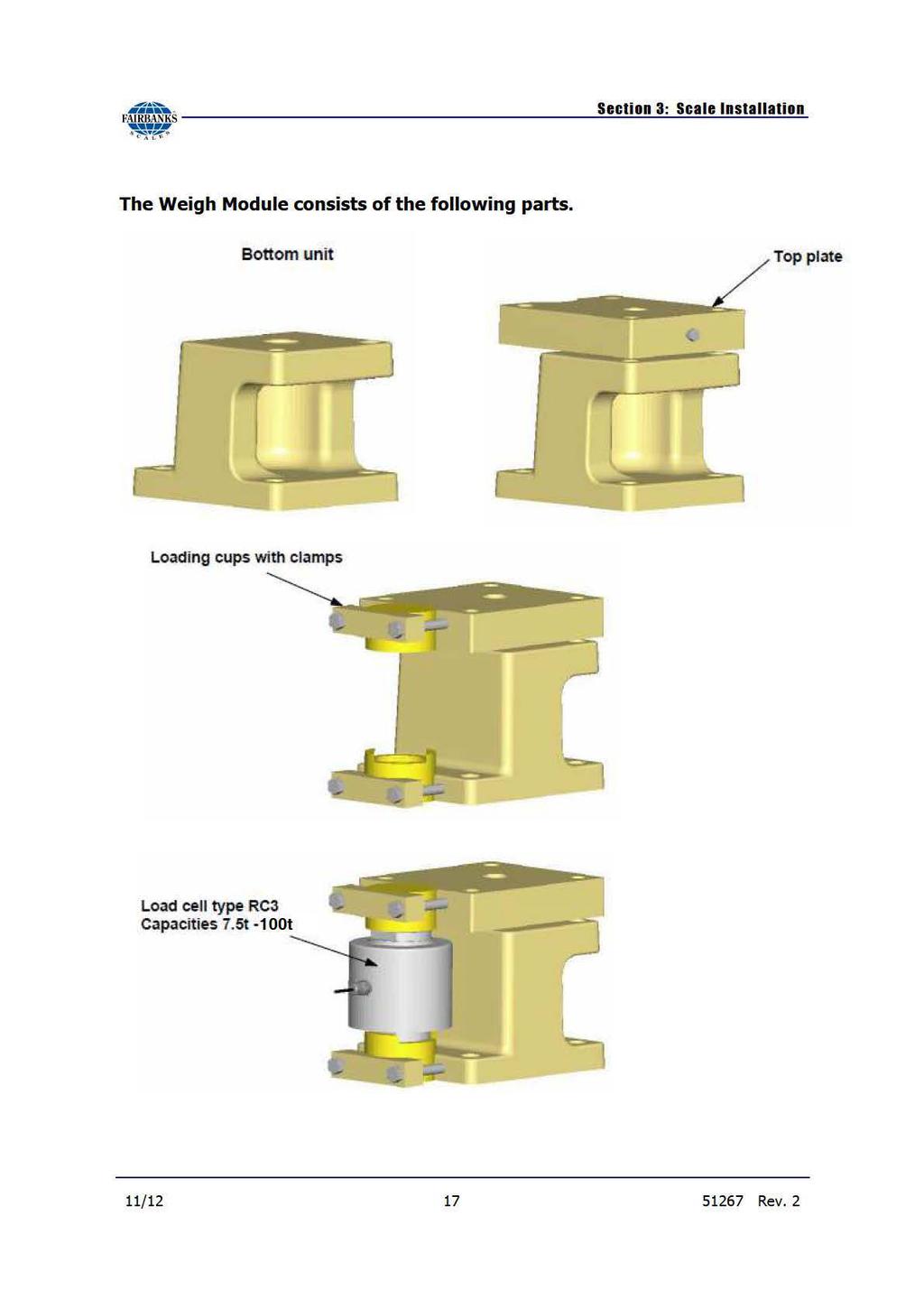
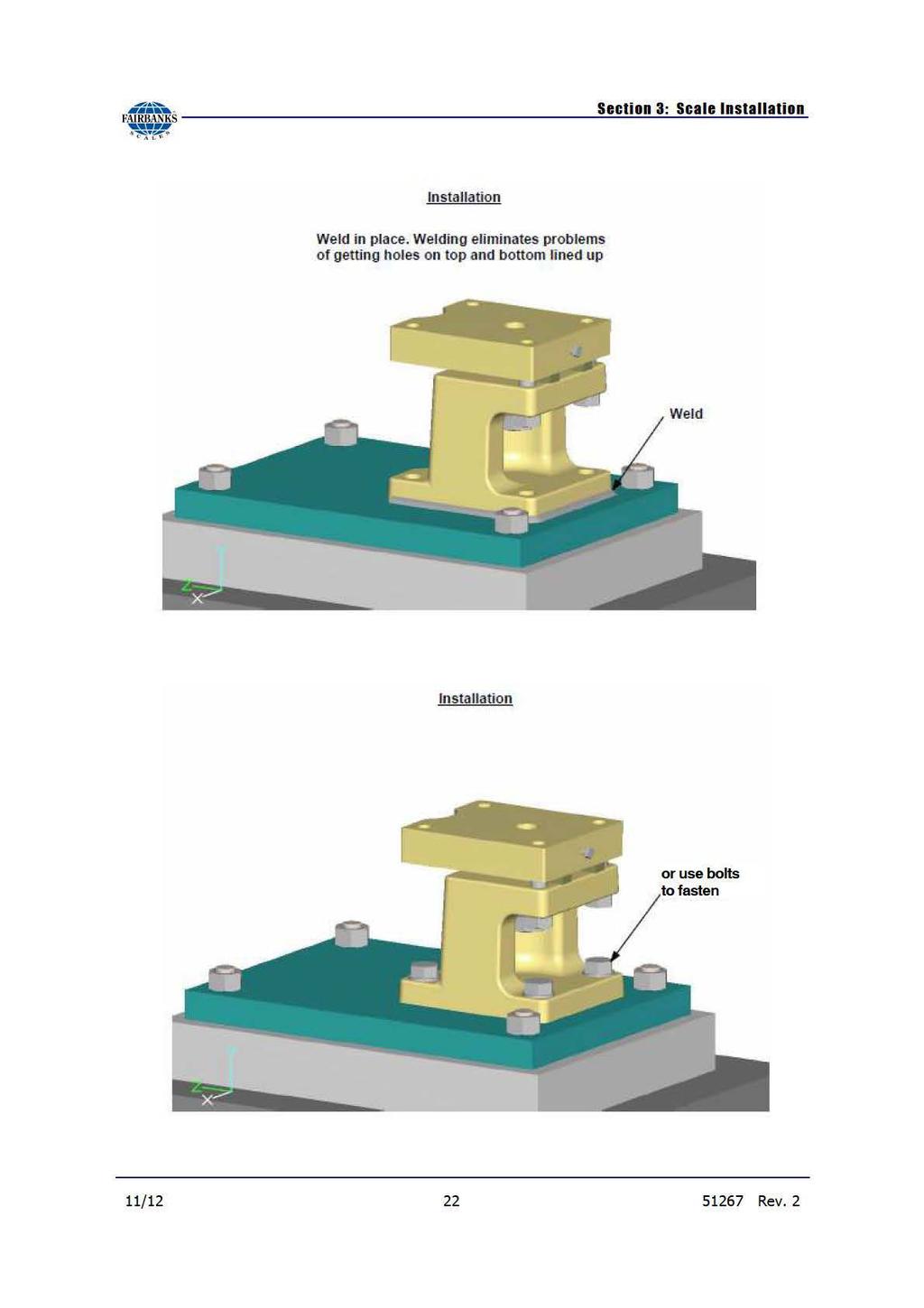
6 Section 1: General Information INTRODUCTION This manual provides general installation and maintenance instructions for the Fairbanks Scales 9120 Series Omnicell. Almost every installation is different, so please adjust the following information, as needed, for your application. Specifications, parameters and application notes are included. This manual is meant to give general instructions for applying the Omnicell considering its inherent capabilities and limitations; it is not meant to be a scale design manual. Questions concerning specific applications should be directed to the appropriate Product manager. For complete 9120 Series installation you will also need to reference the necessary instrumentation manual. DESCRIPTION Fairbanks Scales Omnicells are a combination of two main components: Mounting assembly (captivates the load cell and provides means to fasten to the vessel and flooring). Load cell (the actual weight detecting device). The 9120 Series Omnicells will arrive preassembled, excluding the load cells. This mounting assembly is specifically designed to be installed without the load cell for easy installation. Load cell installation is done quickly, just prior to calibration. The 9120 Series Omnicells are available in standard capacities ranging from 7.5 t to 100 t. (t = metric tonne.) Higher capacities are available, contact the appropriate Product Manager. The load cells are constructed from stainless steel and are a rocker-column design. The mounting assembly is available in either a zinc-plated or cast mild steel or stainless steel construction. These Omnicells can be welded to the load carrier and the foundation. Welding eliminates problems of getting holes on the top and bottom line up. These assemblies are designed for a welded installation, so welding will not cause any service issues (load cell replacement). 11/ Rev. 2
7 Section 1: General Information The 9120 Series can be installed using mechanical fasteners (nuts and bolts). This installation method eliminates the need for onsite welding. It can also be a combination of welding and mechanical fasteners. For example, the top plate can use mechanical fasteners and the base assembly can be welded. Omnicell systems principle causes of problems are because of mechanical restrictions to, and interaction with, the weigh vessel. The cause is invariable excessive vessel or support deflection that needs be identified, if possible, during the design phase. Close attention should be made to ladders, catwalks, piping, and any items that restrict deflection of the vessel. The 9120 Series Omnicells are commercially approved for applications in the U.S., however Fairbanks Scales recommends contacting your local Weight and Measures Office prior to beginning any Omnicell installation that requires commercial approval. CERTIFICATIONS NTEP CC: / Rev. 2

8
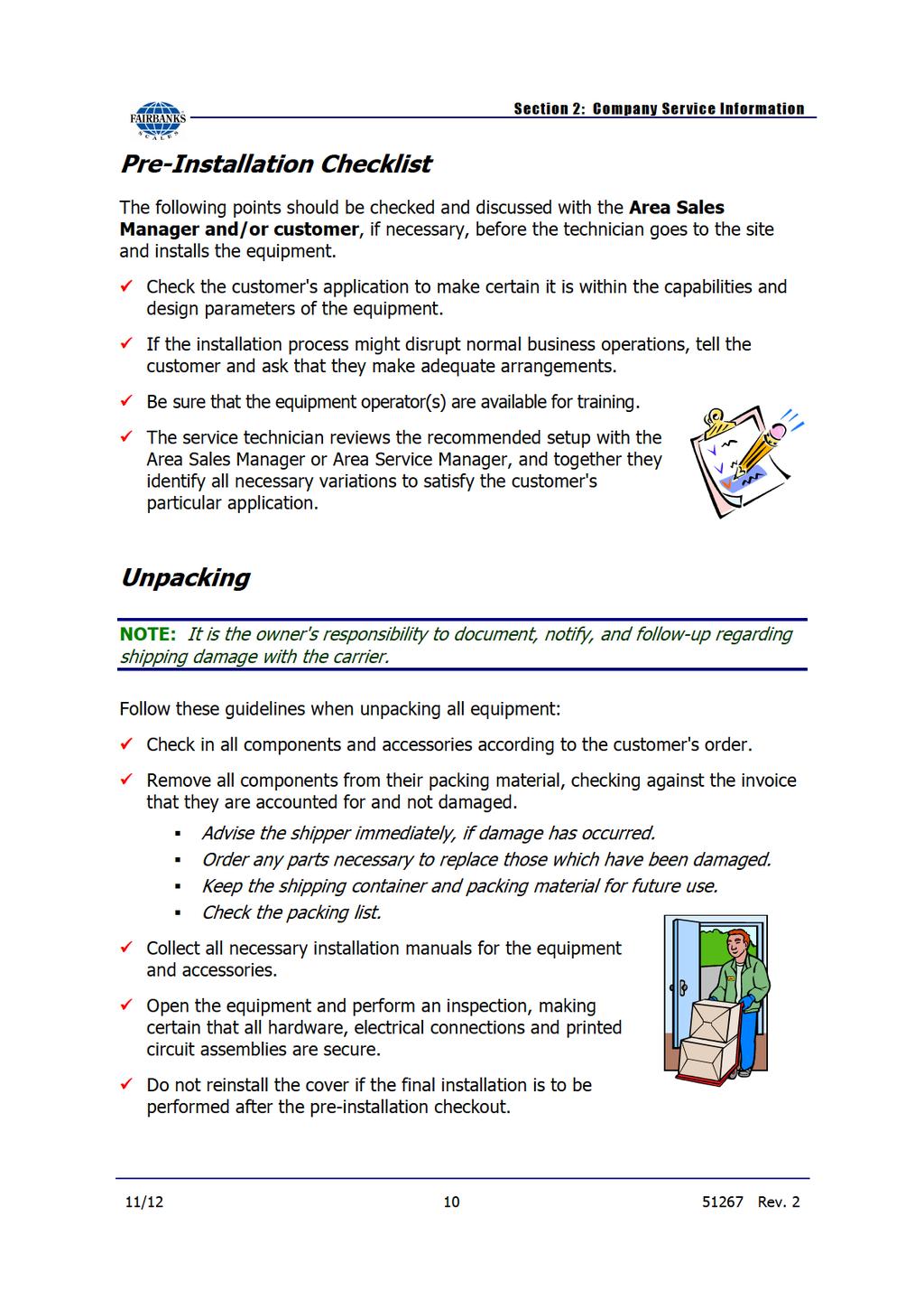
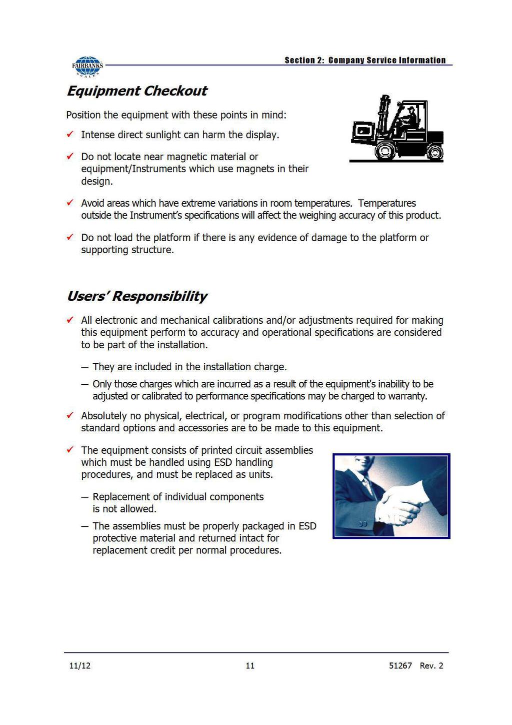
9 Section 2: Company Service Information OVERVIEW Physical Installation Notes Check all devices for proper operation. If any error messages occur, refer to Troubleshooting or the proper manual of that device. Only those charges which are incurred as a result of the equipment's inability to be adjusted to performance specifications may be charged to warranty. No physical alterations (mounting holes, etc.) are allowed during installation. The installing technician is responsible that all personnel are fully trained and familiar with the equipment's capabilities and limitations before the installation is considered complete. All electrical assemblies must be replaced as assemblies or units. Replacement of individual components is not allowed. These components must be returned intact for replacement credit per normal procedures. All electronic and mechanical adjustments are considered to be part of the installation, and are included in the installation charge(s). Included is any required computer programming or upgrades. Included are any accuracy and/or operational specification changes. The AC receptacle / outlet shall be located near the Instrument and easily accessible. Electrical connections other than those specified may not be performed. Conferring with our Client The technician must be prepared to recommend the arrangement of components which provide the most efficient layout, utilizing the equipment to the best possible advantage. The warranty policy must be explained and reviewed with the customer. 11/ Rev. 2
10
11
12 Section 2: Company Service Information Installation Considerations Thorough application review should be conducted before, during and after installation: Determining Omnicell Capacity - Sizing the Omnicell (general rule) Take the overall live and dead load of the vessel. Multiply by 2, then divide by the number of support points (legs, typically). For example: 4 Legs 26,000 lbs dead load 74,000 lbs live load 26, , ,000 x 2 200, ,000 lb for each Omnicell Loading The vessel will have 3, or more, tank legs. The Omnicells should be level and, under extreme cases, shimmed, so that the load is roughly equal on each Omnicell. Flooring - A thorough inspection of the flooring s deflections must be considered before installing an Omnicell system. Flooring must be rigid enough to handle the total load without deflection. Thermal contraction and expansion Horizontal vessels, in direct sunlight, can create thermal expansion issues. The floating rocker column design of the 9120 Series Omnicell easily handles most thermal expansion/contraction issues. Uplift and lateral constraints In extreme conditions (high winds or seismic activity) uplift and lateral stresses on the Omnicell system are a concern and should be considered when choosing the best Omnicell for the application. The 9120 Series Omnicell provides a degree of built-in uplift and lateral checking, refer to the product QuickFacts for a detailed explanation of the forces. In extreme conditions, additional checking is recommended. Isolate vessel Many external factors affect the accuracy and stability of an Omnicell system. Load cell signals can be affected by EMF sources such as electric forklifts, pumps, motors, etc. A well-isolated tank will provide more reliable results with fewer problems. 11/ Rev. 2
13 Section 2: Company Service Information Eliminate mechanical constraints The vessel should be fully supported on the Omnicells. Reduce or eliminate any mechanical issues which will interfere with the vessel s deflection, such as: rigid vertical or horizontal piping (use flexible piping when connecting to the vessel whenever possible), ladders, catwalks, etc. Orientation Orientation of the 9120 Series Omnicell isn t critical because of the rocker load cell design, however it is recommended positioning the load cell cables away from traffic areas. Heated or chilled vessels Consult with the appropriate Product Manager for any application with vessels that heat or chill the product inside the vessel. In these cases, special consideration may be required to isolate the temperatures. Load cell cabling The load cell cables should be routed away from areas where they could be damaged. Use drip loops at both the load cell and the junction box ends. Hazardous area If the Omnicells will be installed in a Hazardous Area, a document is required from the end user stating the Class, Division, and Group. 11/ Rev. 2
14 Section 3: Scale Installation A. Introduction Installation consists of the following: Foundation check, layout, and mounting assembly installation Tools, materials, documentation, and a lifting mechanism (crane or hydraulic jack) Installation of the mounting assemblies Installation of the rocker column load cells B. Preparation for installation 1. Tools, equipment, and materials required: a. Hydraulic jacks -- Use hydraulic jacks that have sufficient capacity plus (+) a safety factor for the size of the vessels you are installing the Omnicells. b. Blocking material to support lifted vessel. c. Determination of how the scale system will be calibrated. Calibration weights (Only application method for NTEP system) i. Get calibration weights on site ii. Dolly, or other method, for moving weights iii. Means for lifting calibration weights (chains, Come-Along winch, etc.) iv. Lifting point on vessel for supporting calibration weights Substitution Product measured by other device (scale, flow meter, etc.) then used as the calibration weight. i. Schedule product to arrive when needed ii. Determine how product will be put into, and removed, from vessel MilliVolt calibration with Intalogix Technology i. Check to make sure the correct equipment was ordered (Q Series instrument and Quad Multiplexer Board or Flash Instrument, Smart Sectional Controller and Pit Power Supply) ii. Load cell calibration sheets d. Determination of how the scale system will be installed. Welded iii. Arc Welding Machine iv. Welding Rod v. Steel Brush vi. Grinder vii. Chipping hammer 11/ Rev. 2
15
16
17
18
19
20
21
22
23
24
25
 to install the load cell.")
26 Section 3: Scale Installation Note: It might be necessary, at this stage of the installation, to slightly lift the vessel (using a jack) to install the load cell. 11/ Rev. 2


27 Section 3: Scale Installation 11/ Rev. 2
28
29 Section 3: Scale Installation 11/ Rev. 2


30 Section 3: Scale Installation 11/ Rev. 2

31 Section 3: Scale Installation 11/ Rev. 2
32
33
34

35 Section 3: Scale Installation 11/ Rev. 2

36 Section 3: Scale Installation 11/ Rev. 2
37
38
39

40 Section 3: Scale Installation 11/ Rev. 2
41 Section 3: Scale Installation 11/ Rev. 2
42 Section 4: Electrical Installation A. Analog Junction box Installation for analog instruments 1. Introduction The analog j-box should be installed on the vessel, and in an easily accessible location, whenever possible. It is recommended that it be installed in a vertical position. 2. Description The analog j-box has four (5) terminal blocks to connect four (4) load cells and one (1) for a cable that connects to the analog instrument. Load cells are adjusted using adjusting potentiometers. 3. Installation a. Boxes: The box has tabs for bolting to mounting brackets on the side of the vessel. Attach the ground wire lug to one of the mounting bolt studs and tighten securely to provide a good electrical ground. b. Wiring: Cable used in all wiring must be a minimum of 24 AWG. Use cable or equivalent. Load cell wiring color codes LCF-HR4020 Black Green Red White YYeel ll looww (-) Excitation (+) Excitation (-) Signal (+) Signal Shield 11/ Rev. 2
43
44 Section 4: Electrical Installation B. Wiring SSCs and PPSs for Intalogix systems 1. Introduction Intalogix systems utilize smart sectional controllers (SSCs) and pit power supplies (PPSes) for load cell excitation and signal processing. 2. Description SSC boxes have four (4) terminals, two (2) for load cells, and two (2) for interconnecting to other SSC boxes or terminating to a pit power supply. Make sure the proper number of SSC boxes are order based on the application requirements. All cell and scale adjustments are made via the Intalogix system instrument. 3. Installation Boxes: The box has tabs for bolting to adapters on the side of the modules. Wiring: Cable used in all wiring must be a minimum of 18 AWG. Use cable or Use appropriate service manual for the instrument being installed. a. Smart Sectional Controller Wire cells into each section s SSC per the appropriate manual. Remember that odd numbered cells go to TB1 location, and even numbered cells go to TB2 location. Load cell drain wires connect to the ground lug on the sectional controller box exterior. b. Grounding SSCs Intalogix systems must have two (2) ground rods in the pit for proper connection. Pit power supplies use a ground separate from the steel and SSC ground rod. c. Instrument-to-PPS cable connection Prepare the cable ends in the standard manner. Use the appropriate manual for wiring instructions of all SSCs and pit power supplies. Connect the instrument interface cable to the instrument in the in the scale house per the instructions in the appropriate indicator service manual. Note: Intalogix installations utilize a different numbering system for load cells because of digital addressing of the SSCs. Number the load cells as follows: With respect to the following starting position, face the vessel from where the instrument is located. The cell at the upper left (far side) of the platform is Cell 1. The cell positions along the far side will be odd cell number, and the near side locations will be even cell numbers. Note: SSCs have connections for two (2) load cells, TB1 and TB2. The oddnumbered cell should go to the TB1 connection, and the even-numbered cell to the TB2 connection. 11/ Rev. 2
45
46 Section 5: Maintenance Scale Maintenance 1. Check for accumulations of solid material under the Omnicells that may affect the accuracy (ice, frozen mud, debris). 2. Check to see that the customer is doing routine cleaning around the vessel. 3. Inspect load cells for damage to the ends/cables; check cups and O rings for damage. 4. The load cell bearing cups should be inspected, cleaned, and greased annually. 5. Inspect and adjust all check bolts (if applicable) using anti-seize on the threads. 6. Check for all clearances around the scale for any obstructions or interference with the free movement of the platform. 7. Check all check bolt clearances both with and without a concentrated load over each leg (support point), one at a time. 8. Check all load cells for plumb and level. 9. Inspect the boxes for leaks; the interior should be clean and dry. If there is moisture inside, clean and dry it thoroughly. Check all connections at the terminal blocks to ensure they are tight. 11/ Rev. 2
47 Section 6: Parts & Parts Replacement 9120 Series Omnicell Complete Assembly Series, 7.5t, Zinc plated mount, Stainless Rocker Load Cell Series, 7.5t, Stainless mount, Stainless Rocker Load Cell Series, 15t, Zinc plated mount, Stainless Rocker Load Cell Series, 15t, Stainless mount, Stainless Rocker Load Cell Series, 22.5t, Zinc plated mount, Stainless Rocker Load Cell Series, 22.5t, Stainless mount, Stainless Rocker Load Cell Series, 30t, Zinc plated mount, Stainless Rocker Load Cell Series, 30t, Stainless mount, Stainless Rocker Load Cell Series, 40t, Zinc plated mount, Stainless Rocker Load Cell Series, 40t, Stainless mount, Stainless Rocker Load Cell Series, 50t, cast mount, Stainless Rocker Load Cell Series, 50t, Stainless mount, Stainless Rocker Load Cell Series, 100t, cast mount, Stainless Rocker Load Cell Series, 100t, Stainless mount, Stainless Rocker Load Cell Series, 150t, cast mount, Stainless Rocker Load Cell Series, 150t, Stainless mount, Stainless Rocker Load Cell Series, 300t, cast mount, Stainless Rocker Load Cell Series, 300t, Stainless mount, Stainless Rocker Load Cell 11/ Rev. 2
48 Section 6: Parts Parts lists, continued 9120 Series Mounting Assembly Series, 7.5t, Zinc plated mounting assembly Series, 7.5t, Stainless mounting assembly Series, 15t, Zinc plated mounting assembly Series, 15t, Stainless mounting assembly Series, 22.5t, Zinc plated mounting assembly Series, 22.5t, Stainless mounting assembly Series, 30t, Zinc plated mounting assembly Series, 30t, Stainless mounting assembly Series, 40t, Zinc plated mounting assembly Series, 40t, Stainless mounting assembly Series, 50t, Zinc plated mounting assembly Series, 50t, Stainless mounting assembly Series, 100t, Zinc plated mounting assembly Series, 100t, Stainless mounting assembly Series, 150t, Zinc plated mounting assembly Series, 150t, Stainless mounting assembly Series, 300t, Zinc plated mounting assembly Series, 300t, Stainless mounting assembly 9120 Series Load Cells - Replacement Rocker Column, 3.5" tall, 7.5t Capacity, Stainless Steel, 40' Cable Rocker Column, 3.5" tall, 15t Capacity, Stainless Steel, 40' Cable Rocker Column, 3.5" tall, 22.5t Capacity, Stainless Steel, 40' Cable Rocker Column, 5.5" tall, 30t Capacity, Stainless Steel, 60' Cable Rocker Column, 6.0" tall, 40t Capacity, Stainless Steel, 60' Cable Rocker Column, 7.0" tall, 50t Capacity, Stainless Steel, 60' Cable Rocker Column, 7.0" tall, 100t Capacity, Stainless Steel, 60' Cable Rocker Column, 8.3" tall, 150t Capacity, Stainless Steel, 60' Cable Rocker Column, 11.0" tall, 300t Capacity, Stainless Steel, 60' Cable 11/ Rev. 2
49 Section 6: Parts Parts lists, continued Part Number Part Description Saddle, 7.5t to 22.5t capacity, zinc-plated mild steel Saddle, 30t to 40t capacity, zinc-plated mild steel Saddle, 50t to 100t capacity, zinc-plated mild steel Saddle, 7.5 to 22.5t capacity, stainless steel Saddle, 30 to 40t capacity, stainless steel Saddle, 50 to 100t capacity, stainless steel Shipping Spacer, 7.5 to 22.5t capacity, zinc-plated mild steel Shipping Spacer, 30 to 40t capacity, zinc-plated mild steel Shipping Spacer, 50 to 100t capacity, zinc-plated mild steel Lift off bolt washer, 7.5 to 22.5t capacity, zinc-plated mild steel Lift off bolt washer, 30 to 40t capacity, zinc-plated mild steel Lift off bolt washer, 50 to 100t capacity, zinc-plated mild steel Lift off bolt washer, 7.5 to 22.5t capacity, stainless steel Lift off bolt washer, 30 to 40t capacity, stainless steel Lift off bolt washer, 50 to 100t capacity, stainless steel K L M N Grounding Cable, 7.5 to 40t capacity Grounding Cable, 50 to 100t Capacity Grounding Cable, 150t capacity Grounding Cable, 300t capacity Loading cup, anti-rotation, 7.5 to 22.5k capacity, mild steel Loading cup, anti-rotation, 30t capacity, mild steel Loading cup, anti-rotation, 40t capacity, mild steel Loading cup, anti-rotation, 50t capacity, mild steel Loading cup, anti-rotation, 100t capacity, mild steel Loading cup, anti-rotation, 7.5 to 22.5t capacity, stainless steel Loading cup, anti-rotation, 30t capacity, stainless steel Loading cup, anti-rotation, 40t capacity, stainless steel Loading cup, anti-rotation, 50t capacity, stainless steel Loading cup, anti-rotation, 100t capacity, stainless steel Loading cup, 7.5 to 22.5t capacity, mild steel Loading cup, 30 to 40t capacity, mild steel Loading cup, 50t capacity, mild steel Loading cup, 100t capacity, mild steel Loading cup, 7.5 to 22.5t capacity, stainless steel Loading cup, 30 to 40t capacity, stainless steel Loading cup, 50t capacity, stainless steel Loading cup, 100t capacity, stainless steel Series Top Plate, 7.5 to 22.5t capacity, zinc-plated Series Top Plate, 30 to 40t capacity, zinc-plated Series Top Plate, 50 to 100t capacity, cast mild steel Series Top Plate, 7.5 to 22.5t capacity, stainless Series Top Plate, 30 to 40t capacity, stainless Series Top Plate, 50 to 100t capacity, stainless 11/ Rev. 2
50 Section 6: Parts A A A B B B 9120 Series Base Assembly, 7.5 to 22.5t capacity, zinc-plated 9120 Series Base Assembly, 30 to 40t capacity, zinc-plated 9120 Series Base Assembly, 50 to 100t capacity, cast mild steel 9120 Series Base Assembly, 7.5 to 22.5t capacity, stainless 9120 Series Base Assembly, 30 to 40t capacity, stainless 9120 Series Base Assembly, 50 to 100t capacity, stainless 79-O O-ring, load cell cup, 7.5 to 22.5t capacity, x O O-ring, load cell cup, 30 to 40t capacity, 39,96 x O O-ring, load cell cup, 50t capacity, x O O-ring, load cell cup, 50t capacity, x Shipping bolts, 7.5 to 22.5t capacity, M16x40-8.8, galvanized Shipping bolts, 30 to 40t capacity, M20x60x8.8, galvanized Shipping bolts, 50 to 100t capacity, M24x80-8.8, galvanized Shipping bolts, 7.5 to 22.5t capacity, M16x40-8.8, stainless Shipping bolts, 30 to 40t capacity, M20x60x8.8, stainless Shipping bolts, 50 to 100t capacity, M24x80-8.8, stainless Uplift bolt set screw, 7.5 to 22.5t capacity, M8x65-8.8, galvanized Uplift bolt set screw, 30 to 40t capacity, M10x90-8.8, galvanized Uplift bolt set screw, 50 to 100t capacity, M10x , galvanized Uplift bolt set screw, 7.5 to 22.5t capacity, M8x65-8.8, stainless Uplift bolt set screw, 30 to 40t capacity, M10x90-8.8, stainless Uplift bolt set screw, 50 to 100t capacity, M10x , stainless Uplift Bolt, 7.5 to 22.5t capacity, M24x65-8.8, galvanized Uplift bolt, 30 to 40t capacity, M30x90-8.8, galvanized Uplift bolt, 50 to 100t capacity, M36x , galvanized Uplift bolt, 7.5 to 22.5t capacity, M24x65-8.8, stainless Uplift bolt, 30 to 40t capacity, M30x90-8.8, stainless Uplift bolt, 50 to 100t capacity, M36x , stainless Hex head screw ground strap, 7.5 to 22.5t capacity, M8x12-8.8, galvanized Hex head screw ground strap, 30 to 40t capacity, M8x12-8.8, galvanized Hex head screw ground strap, 50 to 100t capacity, M8x12-8.8, galvanized Hex head screw ground strap, 7.5 to 22.5t capacity, M8 x , stainless Hex head screw ground strap, 30 to 40t capacity, stainless Hex head screw ground strap, 50 to 100t capacity, stainless Hex head screw Saddle, 7.5 to 22.5t capacity, M8x60-8.8, galvanized Hex head screw Saddle, 30 to 40t capacity, M10x65-8.8, galvanized Hex head screw Saddle, 50 to 100t capacity, M12x90-8.8, galvanized Hex head screw Saddle, 7.5 to 22.5t capacity, M8x60-8.8, stainless Hex head screw Saddle, 30 to 40t capacity, stainless Hex head screw Saddle, 50 to 100t capacity, stainless 11/ Rev. 2
51
52
53
54 Section 6: Parts Replacing an RC load cell 1. Remove power from the instrument. 2. Lift the scale using a proper size and rated hydraulic jack (or jacks) at the corners closest to the defective load cell location. 3. Check upper and lower receiving cups and O rings for damage. Replace as necessary and reapply grease. 4. Insert the new cell into the upper receiving cup. 5. Carefully lower the hydraulic jack until the cell is set into the lower cup. 6. Remove the cover of the J-box, then loosen the gland bushing to free the cable. Remove the old cell wires and connect new cell wires in the balance box/ssc. Secure the cover. 7. Test and adjust the scale as necessary. 11/ Rev. 2
55
56 Appendix I: Specifications Capacities Mount construction 7.5 t to 100 t Zinc-plated mild steel/cast mild steel (50 t & 100 t); stainless steel Load cell: Full scale output (FS) 2.0 mv/v/ohm ± 0.1% Combined error Non-linearity Creep error (20 min.) Compensated temperature Excitation voltage 0.02% FS 0.05% FS 0.03% FS 14 F to 104 F (-10 C to 40 C) 5-15 VDC Overload Safe = 150%; Ultimate = 300% Sideload Uplift Bridge resistance Construction Cable Approvals 25% (min) on 50 t capacity ; 15% (min) on 100 t capacity 50% (min) on 50 t capacity ; 30% (min) on 100 t capacity 1000 ohms nominal Stainless steel 17-4 PH Polyurethane: 40 ft. on capacities 22.5 t; 60 ft. on capacities 30 t NTEP #97-078, Factory Mutual 11/ Rev. 2
57
58 9120 Series Omnicell Manufactured by Fairbanks Scales, Inc. 821 Locust St. Kansas City, MO INSTALLATION MANUAL DOCUMENT 51267
Installation Manual. Titan Series Truck Scale Series by Fairbanks Scales, Inc.
 Installation Manual Titan Series Truck Scale 6020 Series 51351 All rights reserved. Revision 4 10/2016 2015-2016 by Fairbanks Scales, Inc. Disclaimer Every effort has been made to provide complete and
Trident Precast Concrete Deck Truck Scale
 Installation Manual Trident Precast Concrete Deck Truck Scale 2018 by Fairbanks Scales, Inc. All rights reserved 51354 Revision 6 10/18 Amendment Record TRIDENT PRECAST CONCRETE DECK TRUCK SCALE Document
TITAN Motor Truck Scale
 S C A L E S Instruction Manual TITAN Motor Truck Scale Model: 00 Series FAIRBANKS 00 by Fairbanks Scales Inc. All rights reserved 0 Revision # 0/0 Amendment Record Titan 00 Series Motor Truck Scale 0 Manufactured
Reliant Series Floor Scale
 Installation Manual Reliant Series Floor Scale Model: 3300 2005 by Fairbanks Scales. All rights reserved 50783 Issue 2 10/06 Amendment Record Reliant Series Floor Scale Model: 3300 50783 Manufactured by
TALON SERIES. Motor Truck Scale HV Series HVX Series. Instructional Manual by Fairbanks Scales, Inc. All rights reserved
 Instructional Manual TALON SERIES Motor Truck Scale HV Series HVX Series 2014-2016 by Fairbanks Scales, Inc. All rights reserved 51349. Revision 7 10/2016 AMENDMENT RECORD Talon Series Motor Truck Scale
Aegis Industrial Mild Steel Floor Scale
 Installation Manual Aegis Industrial Mild Steel Floor Scale 51102 2008-2016 by Fairbanks Scales, Inc. Revision 9 02/16 All rights reserved Amendment Record AEGIS INDUSTRIAL MILD STEEL FLOOR SCALE Document
Titan Series Portable Vehicle Scale
 FAIRBANKS s c a l e FAIRBANKS s c a l e Installation Manual Titan Series Portable Vehicle Scale 00 by Fairbanks Scales Inc. All rights reserved 0 Issue # 0/0 Amendment Record Titan Series Portable Vehicle
Installation Manual. Talon Series. Portable Vehicle Scale by Fairbanks Scales, Inc. All rights reserved.
 Installation Manual Talon Series Portable Vehicle Scale 2007-2012 by Fairbanks Scales, Inc. All rights reserved 51158 Revision 5 12/12 Disclaimer Every effort has been made to provide complete and accurate
Aegis Industrial Stainless Steel Floor Scale
 Installation Manual Aegis Industrial Stainless Steel Floor Scale 51103 2008-2017 by Fairbanks Scales, Inc. Revision 3 05/17 All rights reserved Amendment Record AEGIS INDUSTRIAL STAINLESS STEEL FLOOR
Aegis Drum Scale Aegis Drum Scale with Backstop
 Installation Manual Aegis Drum Scale Aegis Drum Scale with Backstop Aegis Stainless Steel Drum Scale, shown with optional Ramp and Integral Pillar 51190 2008-2016 by Fairbanks Scales, Inc. Revision 6 09/2016
Fairbanks Transport Scale
 Installation Manual Fairbanks Transport Scale 51191 2008-2010 by Fairbanks Scales, Inc. Revision 2 04/10 All rights reserved Amendment Record AEGIS TRANSPORT SCALE Document 51191 Manufactured by Fairbanks
Operator s Manual. Fairbanks FH Series by Fairbanks Scales, Inc. All rights reserved. . Revision 1 06/2017
 Operator s Manual Fairbanks FH Series 2017 by Fairbanks Scales, Inc. All rights reserved 51393. Revision 1 06/2017 Amendment Record Fairbanks FH Series Operator s Manual Operator s Manual Document 51393
RoughDeck TM FXB Flexure Base Floor Scale. Installation/Operation Manual
 RoughDeck TM FXB Flexure Base Floor Scale Installation/Operation Manual SM 32958 13 Contents 1. Introduction... 1 1.1 Scale Components... 1 1.2 Operating Requirements... 2 1.3 How Flexure Levers Work...
Diamondback Truck Scale
 Installation Manual Diamondback Truck Scale Portable Vehicle Scale 8560 PV Series 2007-2018 by Thurman Scale Inc. All rights reserved 51162 Revision 7 03/18 Disclaimer Every effort has been made to provide
INSTALLATION & MAINTENANCE MANUAL
 A Subsidiary of Dynamic Instruments INSTALLATION & MAINTENANCE MANUAL A Subsidiary of Dynamic Instruments 3860 Calle Fortunada San Diego, CA 92123-1825 Phone: 1-(800) 821-5831 Web Site: hardyinst.com (858)
EZ Mount 1. Load Cell Mounting Kit. Installation Guide
 EZ Mount 1 Load Cell Mounting Kit Installation Guide 9 25710 Contents 1. Introduction... 1 2. Mechanical Installation... 2 2.1 General Installation Guidelines for Tank Mounts... 2 2.2 Installing the EZ
TRANSDUCER INSTRUCTION MANUAL... TYPE SLIM CELL TRANSDUCER. INSTRUCTION NUMBER: AO of 9
 CLEVELAND-KIDDER SLIM CELL TRANSDUCER INSTRUCTION MANUAL... TYPE SLIM CELL TRANSDUCER INSTRUCTION NUMBER: AO-70165 1 of 9 1.0 GENERAL INFORMATION 1.1 RECEIVING AND UNPACKING Handle and unpack the equipment
MagnaMount. Weigh Module Kit. Installation Guide
 MagnaMount Weigh Module Kit Installation Guide 25707 Contents 1. Introduction... 1 2. Parts Assembly... 2 2.1 Assembling the Base Plate... 2 2.2 Assembling the Retaining Plate... 3 2.3 Assembling the Dummy
INSTALLATION & MAINTENANCE MANUAL HI LPD SERIES LOAD POINT ASSEMBLY Calle Fortunada San Diego, CA
 INSTALLATION & MAINTENANCE MANUAL 3860 Calle Fortunada San Diego, CA 92123-1825 Phone: 1-(800) 821-5831 Web Site: hardyinst.com (858) 278-2900 Fax: (858) 278-6700 HI LPD SERIES LOAD POINT ASSEMBLY NOTICE
PORTABLE AXLE LOAD SCALE
 PORTABLE AXLE LOAD SCALE WIDE RANGE OF APPLICATIONS The PALS is right for truck scale applications with anticipated daily weighments of 50 trucks or less. Here are a few examples of industries and applications
Operators Manual. FHX Series by Fairbanks Scales, Inc. All rights reserved. . Revision 1 07/2017
 Operators Manual FHX Series 2017 by Fairbanks Scales, Inc. All rights reserved 51395. Revision 1 07/2017 Amendment Record FHX Series Operators Manual Operators Manual Document 51395 Fairbanks Scales 821
HI HLPT SERIES LOAD POINT ASSEMBLIES OPERATION AND INSTALLATION MANUAL
 HI HLPT SERIES LOAD POINT ASSEMBLIES OPERATION AND INSTALLATION MANUAL Corporate Headquarters 9440 Carroll Park Drive, Ste. 150 San Diego, CA 92121 Phone: (858) 278-2900 FAX: (858) 278-6700 Web-Site: http://www.hardysolutions.com
GSE Tank Mounts. Integrated Tank Assembly (ITA) Model 6600 & 6700 Series LeverMount. User Manual
 Model 6600 & 6700 Series LeverMount. User Manual") GSE Tank Mounts Integrated Tank Assembly (ITA) Model 6600 & 6700 Series LeverMount User Manual 39-10-42089 Issue AF July 2009 Avery Weigh-Tronix group of companies 2009. All rights reserved. No part of
GSE Tank Mounts Integrated Tank Assembly (ITA) Model 6600 & 6700 Series LeverMount User Manual 39-10-42089 Issue AF July 2009 Avery Weigh-Tronix group of companies 2009. All rights reserved. No part of
37SCENE 46SCENE 79SCENE
 Installation and Operation Instructions LED SCENE LIGHT LED SCENE LIGHT 37SCENE 46SCENE 79SCENE 37SCENE 46SCENE Introduction The 37SCENE, 46SCENE, 79SCENE LED Scene Lights are designed for the emergency
Porta-Tronic. Portable Scales. INSTALLATION GUIDE Version 2.0
 Porta-Tronic Portable Scales INSTALLATION GUIDE Version 2.0 GSE Porta-Tronic Installation Guide Copyright 2008 GSE. All rights reserved. Published by: GSE 1525 Fairlane Circle Allen Park, MI 48101 www.gse-inc.com
PROVEX Installation Guide. Version 1.0
 Version 1.0 INTRODUCTION The scale must not be loaded beyond its capacity. Do not select a site where overweight load would have to maneuver to avoid crossing the platform. Avoid areas where the scale
HDI inch Choke Position Indicator User s Manual Rev Indicator Gauge Linear Potentiometer
 HDI 2522 4-inch Choke Position Indicator User s Manual Rev 2 New 2522 Indicator Gauge Linear Potentiometer w/open Housing 2200 Indicator Gauge Linear Potentiometer TABLE OF CONTENTS HDI 2522 4-inch Indicator
HATCHGRIP Installation Instructions/Operation and Maintenance Manual
 HATCHGRIP Installation Instructions/Operation and Maintenance Manual Models: HTG-PCG Contact Information Table of Contents: Safety Precautions... 2 Product Information... 2 Operation... 3 Installation
COOPER POWER SERIES. 200 A loadbreak junction 15 and 25 kv class installation instructions. Loadbreak Connectors MN650015EN
 Loadbreak Connectors MN650015EN Effective December 2015 Supersedes S500-15-1 October 2013 COOPER POWER SERIES 200 A loadbreak junction 15 and 25 kv class installation instructions DISCLAIMER OF WARRANTIES
L007 LIQUID LEVEL FLOAT SWITCH. Side-Mounted Liquid Level Float Switch INSTALLATION AND OPERATIONS MANUAL
 L007 LIQUID LEVEL FLOAT SWITCH INSTALLATION AND OPERATIONS MANUAL Side-Mounted Liquid Level Float Switch READ THIS MANUAL PRIOR TO INSTALLATION This manual provides information on the L007 Side- Mounted
RL1900 SERIES. Mounting Assembly Kit. Installation Guide
 RL1900 SERIES Mounting Assembly Kit Installation Guide 9 SM 25711 Contents 1. Introduction... 1 2. Mechanical Installation... 2 2.1 General Installation Guidelines for Tank Mounts... 2 2.2 Installing the
SWB505 MultiMount. SWB605 PowerMount. Right the First Time Safe, Accurate, Service Friendly. Right the First Time
 SWB505 MultiMount SWB605 PowerMount Right the First Time Safe, Accurate, Service Friendly Tank Weighing SWB505 MultiMount / SWB605 PowerMount weigh modules offer rugged construction and many features for
COOPER POWER SERIES. 600 A 15, 25, and 35 kv Class Cleer Loadbreak Bushing Insert Installation Instructions. Loadbreak/Deadbreak Connectors MN650016EN
 Loadbreak/Deadbreak Connectors MN650016EN Effective July 2018 Supersedes January 2018 COOPER POWER SERIES 600 A 15, 25, and 35 kv Class Cleer Loadbreak Bushing Insert Installation Instructions DISCLAIMER
COOPER POWER SERIES. 200 A Fused Loadbreak Elbow Connector Replacement Fuse Installation Instructions. Fusing Equipment MN132021EN
 Fusing Equipment MN132021EN Effective November 2016 Supersedes June 2011 (S240-97-1) COOPER POWER SERIES Installation Instructions DISCLAIMER OF WARRANTIES AND LIMITATION OF LIABILITY The information,
Model 616 Rotating Disk Electrode Instruction Manual
 Model 616 Rotating Disk Electrode Instruction Manual 219303 C / 1202 Printed in USA Advanced Measurement Technology, Inc. a/k/a Princeton Applied Research, a subsidiary of AMETEK, Inc. WARRANTY Princeton
Load Cell for Manually Operated Presses Model 8451
 w Technical Product Information Load Cell for Manually Operated Presses 1. Introduction... 2 2. Preparing for use... 2 2.1 Unpacking... 2 2.2 Using the instrument for the first time... 2 2.3 Grounding
Displacement Sensor. Model 8739, 8740, 8741
 w Technical Product Information Displacement Sensor 1. Introduction... 2 2. Preparations for use... 2 2.1 Unpacking... 2 2.2 Grounding and potential connection... 2 2.3 Storage... 2 3. Principle of operation...
Motoweigh Dynamic In-motion Checkweighing System. Installation Manual
 Motoweigh Dynamic In-motion Checkweighing System TM Installation Manual 109237 Contents About This Manual... 1 1.0 Introduction and Theory of Operation... 1 1.1 Hardware Requirements...........................................................
SWC515 PinMount. Right the First Time Safe, Accurate, Service Friendly. SWC515 PinMount. Right the First Time
 SWC515 PinMount Right the First Time Safe, Accurate, Service Friendly Tank Weighing SWC515 PinMount weigh modules offer rugged construction and many features for easy installation and accurate and reliable
F-4600 INLINE ULTRASONIC FLOW METER Installation and Operation Guide
 F-4600 INLINE ULTRASONIC FLOW METER Installation and Operation Guide 11451 Belcher Road South, Largo, FL 33773 USA Tel +1 (727) 447-6140 Fax +1 (727) 442-5699 1054-7 / 34405 www.onicon.com sales@onicon.com
T95 Load Cell Assembly for Silo, Tank & Vessel Weighing and Axle Weighing
 T95 Load Cell Assembly for Silo, Tank & Vessel Weighing and Axle Weighing Capacities 2t to 20t Stainless Steel Load Sensor OIML C3 approved Integrated Lift Off Prevention Load cell is always in Tension
COOPER POWER SERIES. High-voltage primary bushings installation instructions. OEM Equipment MN800008EN
 OEM Equipment MN800008EN Effective February 2016 Supersedes S800-35-2 November 2013 COOPER POWER High-voltage primary bushings installation instructions SERIES DISCLAIMER OF WARRANTIES AND LIMITATION OF
Weigh modules Tank and hopper kits
 Weigh modules Tank and hopper kits Section Contents Tank and Hopper Kits ITCM Isolated Tension Cell Modules... 24 ITCM SS Isolated Tension Cell Modules, Stainless Steel... 26 ITCM HE Isolated Tension Cell
S003 LIQUID LEVEL FLOAT SWITCH. Single or Multi-Point, Vertically-Mounted, Liquid Level Float Switch INSTALLATION AND OPERATIONS MANUAL
 S003 LIQUID LEVEL FLOAT SWITCH INSTALLATION AND OPERATIONS MANUAL Single or Multi-Point, Vertically-Mounted, Liquid Level Float Switch READ THIS MANUAL PRIOR TO INSTALLATION This manual provides information
INSTALLATION GUIDE. High Steer Kit
 AEV30212AE Last Updated: 12/09/16 High Steer Kit Designed for 2007 current Jeep JK Wrangler and Wrangler Unlimited models in all trim levels, including Rubicon, with at least 3.0 of suspension lift. INSTALLATION
Weigh Modules. Section Contents
 Section Contents ITCM Isolated Tension Cell Modules...26 ITCM SS Isolated Tension Cell Modules, Stainless Steel...28 ITCM HE Isolated Tension Cell Modules, Stainless Steel, Welded-seal...30 RL50210 TA
Effective June 2016 New Issue
 Voltage Regulators MN225035EN Effective June 2016 New Issue COOPER POWER SERIES QD8 Quik-Drive Tap-Changer Switch Assembly Kit 5740785B13 and Switch Neutral Stationary Assembly Kit 5791646A48 Installation
Cardinal Scale Armor model EPR electronic truck scale with optional guide rails. Bulletin No. 295G
 Cardinal Scale Armor model 13570-EPR electronic truck scale with optional guide rails Bulletin No. 295G ROBOTIC WELDING QUALITY Cardinal Scale Armor model 13570-EPR-C concrete deck truck scale PLASMA CUTTING
SWB505 MultiMount. Right the First Time Safe, Accurate, Service Friendly. Right the First Time
 SWB505 MultiMount Right the First Time Safe, Accurate, Service Friendly Tank Weighing SWB505 MultiMount weigh modules offer rugged construction and many features for easy installation and accurate and
CLIF MOCK TM. Model 5030 Orifice Fitting. User Manual. Manual No , Rev. B
 CLIF MOCK TM Model 5030 Orifice Fitting User Manual Manual No. 25165003, Rev. B 2007 Cameron International Corporation ( Cameron ). All information contained in this publication is confidential and proprietary
ASSEMBLY DIAGRAM AND ASSEMBLY REFERENCE ULTIMA OLD SCHOOL 2 BELT DRIVE UNITS
 ASSEMBLY DIAGRAM AND ASSEMBLY REFERENCE ULTIMA OLD SCHOOL 2 BELT DRIVE UNITS BELT DRIVE ASSEMBLIES Part# 58-850 2 Old School Belt Drive Assembly - Polished Part# 58-851 2 Old School Belt Drive Assembly
User s Guide. EZ-Bar Livestock Scale WEIGH BARS AND DIGITAL INDICATOR. WB-40 Weigh Bars TS-700 WB Digital Indicator. Guide version 1.
 accurate around the world s i n c e 1 8 9 7 User s Guide EZ-Bar Livestock Scale WEIGH BARS AND DIGITAL INDICATOR WB-40 Weigh Bars TS-700 WB Digital Indicator Guide version 1.3 USER S GUIDE Table of Contents
Effective November 2016 Supersedes February 2012 (S )
") Fusing Equipment MN132033EN Effective November 2016 Supersedes February 2012 (S240-97-2) 200 A Fused Loadbreak Elbow Connector Shorting Bar (solid link) Installation Instructions COOPER POWER SERIES Pulling
Fusing Equipment MN132033EN Effective November 2016 Supersedes February 2012 (S240-97-2) 200 A Fused Loadbreak Elbow Connector Shorting Bar (solid link) Installation Instructions COOPER POWER SERIES Pulling
Part Number Analog EGT Gauge
 Part Number 30-5131 Analog EGT Gauge Figure 1. Wiring Schematic AEM EGT Gauge Parts 1 x 35-5131(B/W) EGT Gauge Assembly 1 x 30-2065 EGT Sensor Thermocouple w/mount 1 x 35-4302 Install Kit (6 Butt Connectors)
Summit 3000 Low-Profile Floor Scale. Installation Manual
 Summit 3000 Low-Profile Floor Scale Installation Manual 76012 Contents 1.0 Introduction and System Overview... 1 1.1 Operating Requirements........................................................... 1
TOPAZ 12 WALL PACK INSTALLATION & MAINTENANCE GUIDE (Part # LIT A)
") TOPAZ 12 WALL PACK INSTALLATION & MAINTENANCE GUIDE (Part # LIT-29499-1A) Contractor: Please read these instructions before starting installation. After installation, please forward this guide to the user
TOPAZ 12 WALL PACK INSTALLATION & MAINTENANCE GUIDE (Part # LIT-29499-1A) Contractor: Please read these instructions before starting installation. After installation, please forward this guide to the user
SUMMIT PUMP Horizontal End Suction Pump Close Coupled and Frame Mounted
 SUMMIT PUMP Horizontal End Suction Pump Close Coupled and Frame Mounted Installation, Operation, and Maintenance Manual 2014 by Summit Pump, Inc. All rights reserved. WARRANTY Pumping units assembled
High-voltage primary bushings installation instructions
 OEM Equipment Effective November 2013 Supersedes April 2013 S800-35-2 High-voltage primary bushings installation instructions DISCLAIMER OF WARRANTIES AND LIMITATION OF LIABILITY The information, recommendations,
OWNER S MANUAL. Model 9880 Intrinsically Safe Air Velocity Meter
 OWNER S MANUAL Model 9880 Intrinsically Safe Air Velocity Meter LIMITATION OF WARRANTY AND LIABILITY Seller warrants the goods sold hereunder, under normal use and service as described in the operator's
Installation, Operation and Maintenance Manual
 Document 479288 Installation, Operation and Maintenance Manual Please read and save these instructions for future reference. Read carefully before attempting to assemble, install, operate or maintain the
Benchmark HD Series Heavy Duty Bench Scale. Installation Manual
 Benchmark HD Series Heavy Duty Bench Scale Installation Manual 93631 Contents 1.0 Introduction... 1 1.1 Benchmark HD Specifications...................................................... 1 2.0 Installation...
SPECIFICATIONS CONTENTS:
 Model 3052A 1,100 Lbs Air Assist 2 Stage Transmission Jack INSTRUCTION MANUAL CONTENTS: Page 1 Specifications Page 2 Warning Information Page 3 Assembly Page 4 Operating Instructions Page 4 Preventative
U00X ULTRASONIC LEVEL SWITCH. Ultrasonic Liquid Level Switches INSTALLATION AND OPERATIONS MANUAL. For Models: U002, U003 & U004
 U00X ULTRASONIC LEVEL SWITCH INSTALLATION AND OPERATIONS MANUAL Ultrasonic Liquid Level Switches For Non-Hazardous Locations For Models: U002, U003 & U004 READ THIS MANUAL PRIOR TO INSTALLATION This manual
Tension and Compression Load Cell Model 8435
 Technical Product Information w Tension and Compression Load Cell 1. Introduction... 2 2. Preparing for use... 2 2.1 Unpacking... 2 2.2 Using the instrument for the first time... 2 2.3 Grounding and potential
SPECIFICATIONS CONTENTS:
 Model 3052 1,100 Lbs 2 Stage Transmission Jack INSTRUCTION MANUAL CONTENTS: Page 1 Specifications Page 2 Warning Information Page 3 Assembly Page 4 Operating Instructions Page 4 Preventative Maintenance
COOPER POWER SERIES. Screened Separable Connectors MN650023EN. Effective October 2016 Supersedes March 2012 (IS )
") Screened Separable Connectors MN650023EN Effective October 2016 Supersedes March 2012 (IS550-60-1) COOPER POWER SERIES DTS1242 Deadbreak Bolted Tee Connector: Interface C for Single Core Cable with Copper
Screened Separable Connectors MN650023EN Effective October 2016 Supersedes March 2012 (IS550-60-1) COOPER POWER SERIES DTS1242 Deadbreak Bolted Tee Connector: Interface C for Single Core Cable with Copper
Owner s Manual & Safety Instructions
 Owner s Manual & Safety Instructions Save Save This This Manual Keep Keep this this manual manual for for the the safety safety warnings warnings and and precautions, assembly, assembly, operating, inspection,
Instruction Manual August milltronics MSI BELT SCALE
 Instruction Manual August 2003 milltronics MSI BELT SCALE Safety Guidelines Warning notices must be observed to ensure personal safety as well as that of others, and to protect the product and the connected
Load cells for a Portable Structure
 Load cells for a Portable Structure Load Restoring force Side force We know that a weighing system must be rigid to get good results. We should also know that a three point system is inherently more stable
COOPER POWER SERIES. Edison Modular Fuse (EMF) Installation Instructions. Fusing Equipment MN132031EN
 Installation Instructions. Fusing Equipment MN132031EN") Fusing Equipment MN132031EN Effective November 2016 Supersedes July 2008 (S240-92-1) COOPER POWER Edison Modular Fuse (EMF) Installation Instructions SERIES DISCLAIMER OF WARRANTIES AND LIMITATION OF LIABILITY
Fusing Equipment MN132031EN Effective November 2016 Supersedes July 2008 (S240-92-1) COOPER POWER Edison Modular Fuse (EMF) Installation Instructions SERIES DISCLAIMER OF WARRANTIES AND LIMITATION OF LIABILITY
L-Series: LIQUID LEVEL FLOAT SWITCH. Single-Point, Vertically-Mounted Liquid Level Float Switch INSTALLATION AND OPERATIONS MANUAL
 L-Series: L001, L002, L003, L170, L175, L176, L177, L178, L180, L190 AND L195 LIQUID LEVEL FLOAT SWITCH INSTALLATION AND OPERATIONS MANUAL Single-Point, Vertically-Mounted Liquid Level Float Switch L001
Manual No: Revision: F. Mag Probe Assembly Manual
 Manual No: 576013-730 Revision: F Mag Probe Assembly Manual Notice Veeder-Root makes no warranty of any kind with regard to this publication, including, but not limited to, the implied warranties of merchantability
What is the secret to our success?
 Australia s Quality Load Cell Manufacturer For over 20 years Delphi has been a reliable source of tension load measurement solutions... What is the secret to our success? TENSION CELLS Delphi Measurement
EL Beam Sensors Standard & SC Versions
 EL Beam Sensors Standard & SC Versions 56801399 Copyright 2008 Slope Indicator Company. All Rights Reserved. This equipment should be installed, maintained, and operated by technically qualified personnel.
1250 LB. CAPACITY MECHANICAL WHEEL DOLLY
 1250 LB. CAPACITY MECHANICAL WHEEL DOLLY 67287 SET-UP AND OPERATING INSTRUCTIONS Visit our website at: http://www.harborfreight.com Read this material before using this product. Failure to do so can result
Installation Operation Maintenance ADDENDUM
 Installation Operation Maintenance ADDENDUM Bulletin #: PS-IOM-HYPO2-0111-A FACTORY SERVICE POLICY If you are experiencing a problem with your Pulsafeeder pump, first review the IOM, and consult the troubleshooting
COOPER POWER SERIES. UltraSIL polymer-insulated D-73P disconnect switches installation instructions. Switches MN008004EN
 Switches MN008004EN Effective April 2016 Supersedes S328-10-1 June 2013 COOPER POWER SERIES UltraSIL polymer-insulated D-73P disconnect switches installation instructions DISCLAIMER OF WARRANTIES AND LIMITATION
Web Tension Technology
 Web Tension Technology GLT Web Tension Transducer Installation Instructions TM051 Rev. B - June, 2006 NOTICE BLH Nobel makes no representation or warranties of any kind whatsover with respects to the contents
MSI SINGLE IDLER BELT SCALE
 MSI SINGLE IDLER BELT SCALE Instruction Manual PL-319 January 2001 33453190 Rev. 1.2 Safety Guidelines Warning notices must be observed to ensure personal safety as well as that of others, and to protect
A22 / A6 MINIATURE FORCE SENSOR
 1 A22 / A6 MINIATURE FORCE SENSOR MODEL A22 ; A6 COMPREHENSIVE ERROR % 0.1 OUTPUT SENSITIVITY mv/v 1.60 ± 0.16 NONLINEARITY %F.S 0.05 REPEATABILITY %F.S 0.05 HYSTERESIS %F.S 0.05 CREEP (5min)%F.S 0.1 ZERO
MODEL PS-4 DIGITAL PORTION SCALE
 MODEL PS-4 DIGITAL PORTION SCALE OWNER S MANUAL CARDINAL SCALE MFG. CO. 8528-M317-O1 Rev A 203 E. Daugherty, Webb City, MO 64870 USA 07/05 Ph: 417-673-4631 Fax: 417-673-2153 www.detectoscale.com Technical
DIGITAL PHYSICIAN Waist-High Scale Models 8430, 8431 & 8437 Operating Instructions
 DIGITAL PHYSICIAN Waist-High Scale Models 8430, 8431 & 8437 Operating Instructions CARDINAL SCALE MFG. CO. 8525-M041-O1 Rev H PO BOX 151 WEBB CITY, MO 64870 Printed in USA 09/04 PH (417) 673-4631 FAX (417)
RENA AF371Feeder Operating Manual. Feeder. Operating Manual. Manual Part #: M AF371 Operations Rev
 Manual Part #: M-3022 Feeder AF371 Operations Rev. 3-16-04 1 RENA AF371 Feeder YOUR RENA AF371 IS DISTRIBUTED BY RENA SYSTEMS INC. SERVICE AND SUPPORT FOR THIS PRODUCT IS PROVIDED BY YOUR RENA DEALER.
Model LA 4100 Time Delay OFF Controller
 ISIMET LA Series Model LA 4100 Time Delay OFF Controller Installation, Operation and Maintenance Manual Application: The Time Delay OFF Controller operates as a single output controller where the application
SUNTURA SOLAR TRACKER
 WindyNation SUNTURA SOLAR TRACKER SOT-TRKS-NF User s Manual Page 1 of 10 WindyNation 08/09/2012 Table of Contents 1 Introduction... 3 1.1 Limited Warranty... 3 1.2 Restrictions... 3 1.3 Warranty Claims
P200 P/I Transducer. Installation, Operation, and Maintenance Instructions INTRODUCTION
 INTRODUCTION Scope This manual provides instructions for the installation, adjustment, maintenance, and parts ordering of the P200 Pneumatic-to-Current P/I Transducer. Due to its over-engineered design,
EZ Carrier 3. Owner s Manual. Keep instructions for future reference
 EZ Carrier vv Owner s Manual Keep instructions for future reference Introduction The EZ Carrier provides all the flexibility you may need to transport your mobility scooter. The features include: The capability
COOPER POWER SERIES. Screened Separable Connectors MN650024EN. Effective October 2016 Supersedes March 2012 (IS )
") Screened Separable Connectors MN650024EN Effective October 2016 Supersedes March 2012 (IS550-61-1) COOPER POWER SERIES DTB1242 Deadbreak Bolted Companion Tee Connector: Interface C for Single Core Cable
Screened Separable Connectors MN650024EN Effective October 2016 Supersedes March 2012 (IS550-61-1) COOPER POWER SERIES DTB1242 Deadbreak Bolted Companion Tee Connector: Interface C for Single Core Cable
INSTALLATION, CALIBRATION & TROUBLESHOOTING MANUAL
 INSTALLATION, CALIBRATION & TROUBLESHOOTING MANUAL Model 7200 Transducers GP:50 2770 Long Road, Grand Island, NY 14072 Tel: 716-773-9300 Fax: 716-773-5019 Email: sales@gp50.com Website: http://www.gp50.com
ZT-1 Tonnage Load Module By Toledo Integrated Systems User s Manual
 ZT-1 Tonnage Load Module By User s Manual 17617 ZT-1 Load Module User s Manual Revision: A ZT-1 User s Manual Installation THIS PAGE INTENTIONALLY LEFT BLANK DOC #17601 Page 2 ZT-1 User s Manual Installation
Installation Instructions/Operation and Maintenance Manual. PS DOORS Contact Information. Website psdoors.com
 Rev. 110717 Ladder Safety Gate Installation Instructions/Operation and Maintenance Manual Models All Models: LSG-15 to LSG-48 Table of Contents Product Information...2 Inspection & Maintenance...2 Warranty
PRO-CLUTCH TM PC-1100-CA Evo Big-Twin. chain drive primary PC-1200-CA Evo Big-Twin. chain drive primary PC-1298-CA
 HOME OF PRIMO BELT DRIVES PRO-CLUTCH TM PC-1100-CA / PC-1200-CA / PC-1298-CA / 1056-0020 INSTALLATION INSTRUCTIONS PC-1100-CA 1986-1989 Evo Big-Twin chain drive primary Pro-Clutch TM Stock Clutch PC-1200-CA
Engineering Specifications
 Engineering Specifications Centerlign Weigh Modules The portions of this specification that have been left blank ( ) should be filled with information about the specific application. Information for the
Installation and Operating Manual
 Model u002 & u003 Installation and Operating Manual Ultrasonic Level Switch 60 Great Hill Road Naugatuck, CT 06770 ph: 203-729-6434 fax: 203-729-6696 www.innovativesensing.com Read this Manual Before Installing
COOPER POWER SERIES. K-Limiter back-up current-limiting fuse installation instructions. Fusing Equipment MN132010EN
 Fusing Equipment MN132010EN Effective February 2016 Supersedes S240-64A-1 October 1998 COOPER POWER K-Limiter back-up current-limiting fuse installation instructions SERIES DISCLAIMER OF WARRANTIES AND
: 1250 gpm in the deck mode : 800 gpm while operating in the ground base - Dual Inlet : 1000 gpm while operating in the ground base - Single Inlet
 APOLLO HI-RISER MONITOR STYLE 3433/3431 INSTALLATION, OPERATING, AND MAINTENANCE INSTRUCTIONS The following is intended to provide the basic instructions for installation, operation and maintenance of
INSTALLATION INSTRUCTIONS FOR FACTORY MUTUAL APPROVED INSTRUMENTS
 INSTALLATION INSTRUCTIONS FOR FACTORY MUTUAL APPROVED INSTRUMENTS PLEASE NOTE Installation instructions must be strictly followed in compliance with Intrinsic Safety National Standard NEC 504 or ANSI/ISA
WEB CONTROL PRODUCTS
 WEB CONTROL PRODUCTS User Manual MB Tension Sensor (i) FORM NO. L-20127-G-0501 In accordance with Nexen s established policy of constant product improvement, the specifications contained in this manual
Weigh Module. Selection Guide.
 Weigh Module Selection Guide www.rlws.com selecting weigh modules Selecting Weigh Modules How to be Confident You re Installing The Best Low-quality, poorly-constructed weigh modules most often result
Installation and Parts Manual for SPANCO PF Series Gantry Cranes
 Manual No. 103-0003 REV. 08/14 Installation and Parts Manual for SPANCO PF Series Gantry Cranes ISO 9001 REGISTERED SPANCO, Inc. 2 INSTALLATION AND PARTS MANUAL FOR PF SERIES GANTRIES TABLE OF CONTENTS