Chiller Design and Application New Technology 11/11/2015
|
|
|
- Joseph Raymond Atkinson
- 6 years ago
- Views:
Transcription
1 Chiller Design and Application New Technology 11/11/2015

2 Byron Hamm I received a graduate degree in Mechanical Engineering from Iowa State University with a specialty in the aerodynamic design of turbomachinery. I worked for over 40 years for a major manufacturer of centrifugal water chillers, having a part in the design of every machine currently produced. After retirement from that company, I joined GEA-consulting and have worked with Midea for more than four years as an engineering consultant. I continue to find this work fascinating, and have found my consulting work to be a continuing education. 2
3 Content Chiller system Compressor design Variable frequency drive Falling film evaporator technology Future trends in compressor technology 3
4 Chiller Systems External and internal considerations 4
5 A typical water chiller consists of - Evaporator to provide cooling water to the air conditioning system Compressor to provide system pressure differential and refrigerant flow Condenser to reject the cooling energy and motor power to the external environment Throttle device to reduce refrigerant pressure from condenser pressure to evaporator pressure This is shown schematically on the following slide 5
6 Typical simple chiller configuration - Chiller performance is determined from simple external measurements 6
7 Chiller system cycle diagram - Saturation line Region of subcooled liquid Region of superheated vapor Saturated liquid line Region of liquid and vapor mixture Saturated vapor line 7
8 Chiller system cycle diagram - Condenser process Throttle process Compression Evaporator process COP = Q evap / KW input Chiller performance is linked to cycle state points and component efficiencies 8
9 How can we improve the chiller performance? The most obvious method is to increase compressor efficiency and decrease mechanical losses. Compressor design always strives for this An additional method is to introduce subcooling into the condenser This increases the evaporator Δ H, decreasing the required mass flow for a given capacity, and thus reducing the amount of power required by the compressor This is shown on the following slide 9
10 Performance enhanced by using condenser subcooling - Subcooling Liquid saturation line Increases ΔH evap and decreases m evap decreasing compressor Wx and increasing COP 10
11 This is easy to accomplish in theory, but more difficult to accomplish in actual practice. In order to achieve subcooling, the subcooler tubes must be contained in a flooded compartment without a liquid/vapor interface. Controlling the liquid level to achieve this at part load is a design challenge. Midea uses an electronic flow control valve which senses condenser liquid level and regulates the refrigerant flow to ensure that subcooling is achieved as designed at all load conditions. 11
12 Another method to enhance chiller performance is to divide the compression process into two parts and use an economizer cycle as shown on the following slides. This enhances chiller performance in two ways: The evaporator ΔH is increased even more than with subcooling. Injection of the economizer vapor into the compression process slightly reduces the isentropic compression work input. This cycle also reduces the amount of discharge superheat that the condenser must remove. An economizer is in essence nothing more than a simple vessel to separate the liquid from the vapor at an intermediate pressure. 12
13 Chiller configuration with economizer - Pressure reduction is done in two steps Vapor is separated and injected into the compresso r 13
14 Chiller system cycle diagram with economizer - Economizer separates liquid and vapor Condenser process Vapor injection intercools the compression process Compression Evaporator process 14
15 Chiller system cycle diagram with economizer - Increases ΔH evap and decreases m evap decreasing compressor Wx and increasing COP Intercooling improves compression efficiency 15
16 Of course, subcooling can be included into the economizer cycle. This will alter the ratio of vapor to liquid that is provided by the economizer. A cycle code is used to evaluate the effects of different amounts of subcooling and the intermediate pressure level of the economizer. All Midea two-stage chillers incorporate the economizer cycle with subcooling for maximum chiller COP. These also incorporate electronic flow control valves to ensure that the liquid refrigerant is distributed to the various parts of the system according to the design intent. This is especially important at part load conditions. 16
17 Compressor design 17
18 Overall approach Design for required performance Cost reduce the design 18
19 Design for required performance The overall approach is to lay out the compressor flow path using a meanline design/analysis code, then examine the details using CFD. If the CFD analysis finds a problem that requires the redesign of a component, then we go back to the meanline analysis and examine the entire flow path to be sure that all components are still matched. The aerodynamic flow path design is done side-by-side with mechanical design to be sure there are no rotordynamic or other mechanical issues, and with review by manufacturing engineers to be sure the design is compatible with the available manufacturing capability. 19
20 Determine compressor basic flow path - Centrifugal compressors are dynamic compression devices they add energy by increasing flow velocity with the impeller and then diffusing this velocity to raise pressure. There are no enclosed volumes as in a positive displacement compressor (reciprocating, scroll, screw, vane, etc.) The governing equation for work input is the Euler equation Wx = (U 2 V θ 2 U 1 V θ 1 ) where U is the rotor velocity, V θ is the flow tangential (swirl) velocity, subscript 1 is the rotor inlet and subscript 2 is the rotor exit 20
21 Making use of the inlet and exit velocity triangles, this equation may be rewritten as Wx = ½( (V V 12 ) + (U U 12 ) + (V V 22 ) ) Change in absolute velocity Relative diffusion Change in radius For a given compressor design, work input is distributed among these components by the choice of impeller inlet and exit blade angles, rotational speed, inlet relative Mach number, and internal flow stability considerations. Different designers will choose different values for these components of energy addition according to what they feel is best. 21
22 Midea uses a meanline design/analysis code to evaluate the best combinations of these variables according to our best engineering judgement. Regardless of the detailed design choices that are made, it is clear that work input and flow velocity are closely related. For a single-stage compressor, the flow velocities are the result of adding the entire compressor work input in a single impeller. Flow velocities are high and the inevitable result is compressor noise. For a two-stage compressor, the work input for each impeller is only one half of the total, so the flow velocities are correspondingly lower. Two-stage compressors are much less noisy than single-stage compressors for this reason. 22
23 Typical two-stage compressor flow path - Volute/conic diffuser Crossover bend Diffuser diameter Vaned/vaneless diffuser Impeller diameter Vaned return channel Diffuser diameter Vaned/vaneless diffuser Impeller diameter First stage impeller Second stage inlet duct Second stage impeller 2
24 Important design decisions Impeller inlet relative Mach number/specific speed? Impeller inlet and exit blade angles? Impeller relative diffusion/d-factor? Stage work input split (impeller diameter ratio)? Vaned or vaneless diffusers? Pinched diffusers? Variable geometry vaneless diffuser? Diffuser radius ratio (and first/second difference)? Crossover bend diffusion? Start/end locations of vanes in vaned return channel? Single-vane vs two-vane return channel (second stage IGVs?)? Configuration of second stage inlet duct (conservation of rv θ ) Volute/conic diffuser geometry? 24
25 In addition to the aerodynamic factors, there may be geometric constraints as well Impeller hub diameter (power transmission, shaft critical speed) Impeller weight/axial spacing (shaft critical speed) Bearings and lubricant feed/drain/seal (shaft critical speed) Maximum casting diameters due to machine tool limitations Minimum volute location due to motor end-winding diameter Second stage IGV linkage (if present) Thrust balance piston and venting (if present) Overall chiller dimension envelope (shipping/application consideration) Material size/weight limitations (material handling within workshop) 25
26 The meanline design/analysis code is used to systematically study this array of variables in order to determine the best overall compressor design within the specified aerodynamic and mechanical constraints. This may include offdesign analysis to estimate range-to-surge, part load performance, etc. This process establishes the basic layout of the compressor. Only then are detailed CFD studies made of the individual components and component assemblies. If the CFD analysis indicates that some component must be redesigned, then the meanline design/analysis code is used to rebalance the entire flowpath to correctly accommodate the redesigned component. 26
27 The meanline design/analysis code evaluates many flow details 27
28 For some refrigerants, the isentropic compression process extends into the wet region. A very efficient compression may also extend into the wet region. Assuming dry compression will introduce fluid property errors. The meanline design/analysis code checks every state point and correctly calculates the refrigerant properties - Saturation line Compression into wet region 28
29 The meanline design/analysis code calculates impeller disk friction and seal leakage - The fluid in the cavity rotates at some fraction of impeller speed This creates a static pressure field Thus, the seal upstream pressure is known for seal leakage calculation The disk friction ΔH Is added to the leakage flow and mixed with the main flow The disk friction work input is also added to the shaft input power The recirculating leakage flow is added to the main flow to calculate impeller dimensions 29
30 The meanline design/analysis code calculates impeller axial thrust - The fluid in the cavities rotates at some fraction of impeller speed This creates static pressure fields Inlet flow has axial momentum mv Pressures are integrated over areas, and all forces are summed to calculate axial thrust 30
31 Impeller exit flow calculation uses the jet-wake model proposed by Japikse Region of high-energy isentropic core flow (jet) Region of low-energy boundary layer flow that accumulates in the suction surface corner (wake) This flow mixes to form the impeller exit flow. CFD analysis will give additional insight into the flow within the impeller 31
32 The blade profiles used in the vaned diffusers and vaned return channel can be either NACA 65-series or Double Circular Arc - NACA 65-series blade Double circular arc blade Either blade profile type may be specified, as well as the thickness/chord ratio, setting angle, camber, incidence, etc. Performance calculation is based on the extensive cascade data and calculation method presented in NASA SP-36, corrected from axial cascade to radial cascade 32
33 The meanline design/analysis code has many available options for cooling the hermetic motor - 33
34 These choices may each be analyzed for impact on cycle performance. A common and simple configuration is motor cooling using liquid from the condenser with vapor return to the evaporator. This is shown schematically below - Liquid from the condenser is fed into the motor cooling system Vapor is returned to the evaporator 34
35 This motor cooling scheme is simple. But note the following details This is a flow of refrigerant that is separate from and in addition to the flow required by the evaporator and condenser for the cooling load. Therefore, the compressor must provide this additional flow, and the compressor flow passage design must be altered accordingly. The condenser must have additional surface to condense this additional flow. The meanline design/analysis code automatically handles all mass flow requirements for any selected motor cooling scheme and incorporates these into the design of the compressor components. In effect, the compressor design is scaled up for both internal seal leakage flows and motor cooling flows. 35
36 Examples of the interaction of aerodynamic design with other design requirements 36
37 Example 1: The second row of vanes in a vaned return channel are made moveable to serve as second stage IGVs. They bind during operation, preventing rotation - Second vane in return channel is moveable to act as second stage IGV 37
38 Problem: In real life, moving parts require clearances. However, operating pressures cause deflection of parts. In this case, during operation the vanes bound against the castings and they could not be moved as designed. Solution: The first solution was to increase clearance on either side of the vanes. However, this caused unacceptable performance loss. The second solution was to strengthen the vanes with a steel insert inside the shaft (the vanes are an aluminum casting), and to strengthen the vane bearing structure and bolt it to a major structural casting. This solved the problem and actually improved performance because the vane clearance could be further reduced. The design team should include aero, mechanical, manufacturing engineers. 38
39 Example 2: FEA indicates impeller stress exceeds yield strength during the impeller overspeed test - Stress in impeller exceeds yield strength during overspeed test 39
40 Problem: FEA analysis indicates that the impellers will have areas of stress exceeding the yield strength of the material during overspeed tests. Various small changes to the design were not effective in reducing this stress (increased blade thickness, increased fillet radius, etc.). That is because, in hindsight, the root problem was the blade design in the inlet area Solution: The impeller vendor suggested a small change in the heat treatment of the impeller to increase the yield strength significantly. Tests showed that this change did not harm the machinability of the material. This change solved the problem without increasing the cost Designs should be done in collaboration with suppliers 40

41 Example 3: FEA indicates impeller deflection at operating speed - Deflection of impeller at operating speed 41
42 Problem: FEA analysis indicates that the impellers will deflect at both the tip and the inlet shroud area at operating speed. This may cause misalignment with the diffuser passage, interference with the surrounding castings, and interference at the inlet seal Solution: Location of the impeller should be done so that the deflected tip will align with the diffuser. Allow clearance around the impeller to avoid interference. Adjust seal clearance to avoid seal interference Component design and the design of surrounding components should consider operating deflections due to rotation, temperature, pressure, etc. 42
43 Example 4: CFD analysis indicates that the flow angle exiting the vaned return channel does not agree with the meanline prediction. Conservation of rv θ means the impeller leading edge will not be aligned with the flow as designed - Conservation of rv θ magnifies errors in flow angle leaving the return channel second blade 43

44 CFD solution for a tandem vane set in the return channel - 44
45 Problem: CFD analysis indicates that the flow leaving the return channel blades will have an exit angle 2-3⁰ different than indicated by the meanline analysis. The inlet duct is an area of conservation of angular momentum (constant rv θ ). Since there is a significant change in radius between the exit of the return channel blades and the impeller inlet, this error is magnified to be about 6-8⁰. The blades of the second stage impeller were designed to match the flow angles indicated by the meanline analysis. Solution: It was decided that the CFD analysis was probably more accurate than the meanline analysis in this area. The design of the second blade of the return channel was redesigned to provide the flow angle required by the impeller design. Various design methods should be compared where practical. 45
46 Cost reduce the design Consideration should be given at the design stage for ease of component manufacturing, ease of proper assembly, ease of service, and system reliability. The number of major castings should be as small as possible consistent with manufacture and assembly, in order to reduce potential leakage joints. External piping for the lubrication and motor cooling systems should have minimum connection points, and be designed for easy service while remaining leak tight. Carefully review the lubrication system, the heat exchanger designs, and the control system for function and cost. 46
47 Variable Frequency Drive 47
48 Variable frequency drive greatly enhances part load performance - Variable frequency drive is used to control capacity by adjusting compressor speed. Head is changed correspondingly. The typical chiller load line has decreasing head as capacity is reduced, so this works well. Variable frequency drive can usually be used down to about 50% of design speed before encountering surge (AHRI part load conditions). Below that, control reverts to IGV but requires much less vane closure due to already decreased capacity from speed reduction. The plot on the next slide shows a comparison of COP for a chiller using VFD down to 50% load and then IGV control at 25% load, compared to the same chiller using only IGV capacity control. The test points are those specified by AHRI for the calculation of IPLV (Integrated Part Load Value). 48
49 Variable frequency drive greatly enhances part load performance - IGV capacity control VFD capacity control Calculated IPLV
50 Variable frequency drive greatly enhances part load performance There is a small penalty at full load due to some efficiency loss in the VFD drive. There is a large performance gain in the mid-range, the test points that weigh most heavily in the calculation of IPLV. The IGV control at 25% load still produces better efficiency because the guide vanes do not have to be closed very much. VFD control is optional on Midea gear-drive compressors. VFD control is required on all high-speed direct-drive compressors in order to achieve the required compressor speeds. 50
51 Falling Film Evaporator Technology 51
52 What is a falling film evaporator, and how is it different from the traditional flooded evaporator? 52
53 Flooded evaporator Dry vapor to compressor Tube bundle Filter to remove liquid droplets Liquid distributor Liquid inlet 53

54 Flooded evaporator Dry vapor to compressor Large vapor space so low velocity flow will not carry liquid droplets into compressor Tube bundle extends to shell to prevent gas bypass Liquid level in shell, optimized so that boiling action just wets the top tubes for maximum performance Flow is distributed evenly along the length of the shell Liquid inlet 54
55 Falling film evaporator Baffle to remove liquid droplets Vapor path for generated vapor Tube bundle Dry vapor to compressor Liquid distributor above top row of tubes Lower tube bundle to evaporator any remaining liquid Liquid inlet 55

56 Falling film evaporator Baffle and vapor space around distributor designed to minimize carryover of liquid droplets to compressor Dry vapor to compressor Vapor must exit the tube bundle and flow around the tube bundle Liquid level in shell Liquid inlet 56
57 How well does this design concept work? 57
58 How well does this design concept work? This test data shows that, if a proper film is developed, all the tubes in the column will have equal heat transfer coefficient. Above a minimum flow rate, the heat transfer coefficient is very constant 58

59 How well does this design concept work? This test data illustrates that the heat transfer coefficient can be higher in a falling film configuration compared to a flooded configuration 59

60 How well does this design concept work? This test data illustrates that different enhanced tube surfaces will have different performance characteristics 60
61 Potential benefits: Reduction in working fluid to about 1/3 of flooded evaporator Better heat transfer performance More uniform heat transfer throughout the evaporator Lower approach temperature More compact evaporator design Superior for oil management (oil holds up in a flooded bundle but drains to the bottom of a falling film evaporator) 61
62 Potential disadvantages: Less design experience with falling film evaporators Uniformity of liquid distribution onto the top tube row is a design challenge Less tolerance for undercharging of the chiller There is more to performance/cost than boiling heat transfer coefficient Does the performance of a falling film evaporator reduce the cost of the tube surface and refrigerant charge enough to offset the added cost of the distributor and flow baffles? 62
63 Charge optimization Charge optimization is the same for either evaporator type find the minimum refrigerant level/flow rate that fully utilizes the heat transfer surface ITD/ΔT or Approach Optimum charge is where the curve flattens out Refrigerant charge ITD = inlet water temperature saturation temperature ΔT = inlet water temperature outlet water temperature Approach = outlet water temperature saturation temperature 63
64 Future Trends in Compressor Technology 64
65 The compressor world is changing: Gen 1 Gen 2 Traditional design High-speed gear-drive Compact size Efficiency + IPLV Gen 3 High-speed direct-drive + VFD (no gears, fewer bearings, permanent magnet motors) (variable speed) 65
66 Increasing compressor speed drives motor development: Gen 1 Gen 2 Gen 3 Traditional induction motor High-speed Induction motor Permanent Magnet motor Compact size Efficiency 66
67 Increasing compressor speed drives bearing development: Oil-lubricated sleeve bearings Oil-lubricated ball bearings Oil-free Magnetic bearings Ceramic ball bearings Gas bearings Foil bearings 67
68 Bearing development will result in new requirements: New manufacturing methods Aerodynamic performance of the compressor due to seal clearance Stiffness and rotordynamic characteristics System requirements Continuing changes to satisfy new requirements of size, cost, efficiency, and oil-free operation In the following slides we will briefly review the pros and cons of several bearing types 68
69 Oil-lubricated sleeve bearings: Pro Traditional design Simple, reliable, and relatively inexpensive Medium clearance requires medium seal clearance and leakage Medium load capability Con Requires lubrication system oil pump, filter, heater, cooler, pressure regulator, piping Requires oil reclaim system Speed limited by increasing bearing losses Misalignment issues may require more expensive pivoted-shoe design Considered the baseline design for this comparison Still perhaps the best solution for the largest lower speed compressors 69
70 Oil-lubricated ball bearings: Pro Well known design methods and operating characteristics Low clearance results in low seal clearance and leakage Low bearing friction Allows higher compressor speed, limited by internal bearing loads High load capability, compact bearing system Con Requires lubrication system oil pump, filter, heater, cooler, pressure regulator, piping Requires oil reclaim system Higher cost than a sleeve bearing Lower loss alternative for all compressor sizes within the speed limitation of this bearing type 70
71 Magnetic bearings: Pro Oil free Known technology, relatively low project risk No bearing friction Can be programmed to eliminate balancing and critical speed issues No compressor speed limit Con Requires complex control system Requires backup bearing system and can be bulky High clearance results in high seal clearance and leakage Expensive Low-loss oil-free alternative for all compressor sizes and speeds, but high required clearance will compromise performance of the smaller compressors If we separate magnetic bearings from permanent magnet motors, they can be used for higher capacity compressors 71
72 Refrigerant lubricated ceramic ball bearings: Pro Oil free Low clearance results in low seal clearance and leakage Lower bearing friction than oil lubricated ball bearings Higher compressor speeds than oil lubricated ball bearings High load capability, compact bearing system No oil reclaim system Con Requires simplified lubrication system pump, filter, piping Newer technology requiring some project development Higher cost than an oil lubricated ball bearing Low-loss oil-free alternative for all compressor sizes within the speed limitation of this bearing type 72
73 Gas (air) bearings (hydrostatic): Pro Oil free Similar in appearance to the simple sleeve bearing, but uses gas pressure to lift the shaft, not a film generated by shaft rotation Very low clearance results in very low seal clearance and leakage Very low bearing friction No compressor speed limit Con Requires external gas source with controlled pressure and temperature Low load capacity requires larger bearings New technology requiring significant project development Very low clearance requires precision manufacture and assembly Cost unknown but likely to be higher than ordinary sleeve bearings Low-loss oil-free alternative for all compressor sizes with no speed limitation Low clearance would be a special benefit for small-medium compressors 73
74 Foil bearings (hydrodynamic gas bearings): Pro Oil free Simple concept that requires no lubrication system at all Higher clearance results in higher seal clearance and leakage Very low bearing friction No known compressor upper speed limit Con Requires high minimum compressor speed, thereby limiting IPLV Operating concept requires low loads and very high speeds New technology requiring significant project development Requires precision manufacture and assembly Cost unknown but likely to be very high Current state of technology is only for very small very high speed machines Requires extensive development for each application 74

75 Approximate range of application of bearing technologies: I believe the newer bearing technologies are best applied at the lower end of the capacity range for relatively small high-speed direct-drive compressors. 75
76 Midea has ongoing projects to evaluate each of these technologies 76


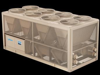


77 Two-stage Falling-film Centrifugal Chillers Chiller Plant System Control Water-cool Falling-film Screw Chillers Air-cool Falling-film Screw Heat Pump

78 78
79 Thank You! 79
Design and Test of Transonic Compressor Rotor with Tandem Cascade
 Proceedings of the International Gas Turbine Congress 2003 Tokyo November 2-7, 2003 IGTC2003Tokyo TS-108 Design and Test of Transonic Compressor Rotor with Tandem Cascade Yusuke SAKAI, Akinori MATSUOKA,
APPLICATION OF STAR-CCM+ TO TURBOCHARGER MODELING AT BORGWARNER TURBO SYSTEMS
 APPLICATION OF STAR-CCM+ TO TURBOCHARGER MODELING AT BORGWARNER TURBO SYSTEMS BorgWarner: David Grabowska 9th November 2010 CD-adapco: Dean Palfreyman Bob Reynolds Introduction This presentation will focus
Study on Flow Fields in Variable Area Nozzles for Radial Turbines
 Vol. 4 No. 2 August 27 Study on Fields in Variable Area Nozzles for Radial Turbines TAMAKI Hideaki : Doctor of Engineering, P. E. Jp, Manager, Turbo Machinery Department, Product Development Center, Corporate
Technical Information
 Date of last update: Sep 12 Ref: Application Engineering Europe COPELAND SCROLL COMPRESSORS USING VAPOUR INJECTION FOR REFRIGERATION CONTENTS 1 Introduction... 2 2 Principle of operation... 2 3 Capacity
Energy Efficient Pumpset & Pumpset Selection. Page 1
 Energy Efficient Pumpset & Pumpset Selection Page 1 Pumpset : 5HP motor means it can deliver up to 5HP brake horse power output power. 5HP pump means it required a minimum of 5HP brake horse power input
(a) then mean effective pressure and the indicated power for each end ; (b) the total indicated power : [16]
![(a) then mean effective pressure and the indicated power for each end ; (b) the total indicated power : [16]](/thumbs/79/80273804.jpg "(a) then mean effective pressure and the indicated power for each end ; (b) the total indicated power : [16]") Code No: R05220304 Set No. 1 II B.Tech II Semester Regular Examinations, Apr/May 2007 THERMAL ENGINEERING-I ( Common to Mechanical Engineering and Automobile Engineering) Time: 3 hours Max Marks: 80 Answer
Code No: R05220304 Set No. 1 II B.Tech II Semester Regular Examinations, Apr/May 2007 THERMAL ENGINEERING-I ( Common to Mechanical Engineering and Automobile Engineering) Time: 3 hours Max Marks: 80 Answer
Emerging Oil Free Technologies. Ray Good Global Director of Application Engineering Danfoss Turbocor Compressors, Inc.
 Emerging Oil Free Technologies Ray Good Global Director of Application Engineering Danfoss Turbocor Compressors, Inc. rgood@danfoss.com 1 Agenda Chiller Overview Benefits of Oil Free Oil Free Compressors
November 8, 2018 GAS TURBINE ENGINE SECONDARY FLOW SYSTEMS
 November 8, 2018 GAS TURBINE ENGINE SECONDARY FLOW SYSTEMS Agenda 1 What is Secondary Flow? Purpose for the Secondary Flow Systems Chargeable Vs Nonchargeable Flows Seals Selection and Leakage Effects
Innovative Centrifugal Compressor Design
 Innovative Centrifugal Compressor Design L. Tarnowski TURBOMECA groupe SAFRAN INTRODUCTION SP2 : IRA (Intercooled Recuperative Aero-engine) Task 2.2.5 HP Centrifugal Compressor Design The challenge is
ROTATING MACHINERY DYNAMICS
 Pepperdam Industrial Park Phone 800-343-0803 7261 Investment Drive Fax 843-552-4790 N. Charleston, SC 29418 www.wheeler-ind.com ROTATING MACHINERY DYNAMICS SOFTWARE MODULE LIST Fluid Film Bearings Featuring
First Domestic High-Efficiency Centrifugal Chiller with Magnetic Bearings: The ETI-MB Series
 82 First Domestic High-Efficiency Centrifugal Chiller with Magnetic Bearings: The ETI-MB Series KENJI UEDA *1 YASUSHI HASEGAWA *2 NAOKI YAWATA *2 AKIMASA YOKOYAMA *2 YOSUKE MUKAI *3 The efficiency and
17/11/2016. Turbomachinery & Heat Transfer Laboratory Faculty of Aerospace Engineering Technion Israel Institute of Technology, Israel
 17/11/2016 Turbomachinery & Heat Transfer Laboratory Faculty of Aerospace Engineering Technion Israel Institute of Technology, Israel 1 Motivation New challenges rise due to increase in demands from small
Scroll Expander for Carbon Dioxide Cycle
 Purdue University Purdue e-pubs International Refrigeration and Air Conditioning Conference School of Mechanical Engineering 26 Scroll Expander for Carbon Dioxide Cycle Detlef Westphalen John Dieckmann
A pump is a machine used to move liquid through a piping system and to raise the pressure of the liquid.
 What is a pump A pump is a machine used to move liquid through a piping system and to raise the pressure of the liquid. Why increase a liquid s pressure? Static elevation a liquid s pressure must be increased
Numerical Simulation and Performance Analysis of Rotary Vane Compressors for Automobile Air Conditioner
 Purdue University Purdue e-pubs International Compressor Engineering Conference School of Mechanical Engineering 24 Numerical Simulation and Performance Analysis of Rotary Vane Compressors for Automobile
A Prototype Oil-Less Compressor for the International Space Station Refrigerated Centrifuge
 Purdue University Purdue e-pubs International Compressor Engineering Conference School of Mechanical Engineering 2000 A Prototype Oil-Less Compressor for the International Space Station Refrigerated Centrifuge
Flow Controlled Core Overview
 Flow Controlled Core Overview Hanna Reiss, Snecma Safran Group Introduction High BPR and/or new architectures will require highly loaded, efficient and operable HPC (+20/25% vs. in-service compressor)
Advanced Aerodynamic Design Technologies for High Performance Turbochargers
 67 Advanced Aerodynamic Design Technologies for High Performance Turbochargers TAKAO YOKOYAMA *1 KENICHIRO IWAKIRI *2 TOYOTAKA YOSHIDA *2 TORU HOSHI *3 TADASHI KANZAKA *2 SEIICHI IBARAKI *1 In recent years,
RECOMMENDATIONS FOR USING FREQUENCY INVERTERS WITH POSITIVE DISPLACEMENT REFRIGERANT COMPRESSORS
 RECOMMENDATIONS FOR USING FREQUENCY INVERTERS WITH POSITIVE DISPLACEMENT REFRIGERANT COMPRESSORS Contents Page 1 Scope and purpose... 1 2 General... 1 3 Operation... 2 4 Application ranges... 5 5 Design
A NOVEL DESIGN METHOD OF VARIABLE GEOMETRY TURBINE NOZZLES FOR HIGH EXPANSION RATIOS
 A NOVEL DESIGN METHOD OF VARIABLE GEOMETRY TURBINE NOZZLES FOR HIGH EXPANSION RATIOS Lei Huang 1, Hua Chen 2, * 1. National Laboratory of Engine Turbocharging Technology, North China Engine Research Institute,
HYDROGEN COMPRESSOR SEAL CASE STUDY UTILIZING HALO (NON-CONTACTING, COMPLIANT) INTER-STAGE, IMPELLER EYE, BUFFER AND FAIL- SAFE SEALS
 INTER-STAGE, IMPELLER EYE, BUFFER AND FAIL- SAFE SEALS") HYDROGEN COMPRESSOR SEAL CASE STUDY UTILIZING HALO (NON-CONTACTING, COMPLIANT) INTER-STAGE, IMPELLER EYE, BUFFER AND FAIL- SAFE SEALS Author Information John Justak, President/CEO of ATGI Over 28 years
HYDROGEN COMPRESSOR SEAL CASE STUDY UTILIZING HALO (NON-CONTACTING, COMPLIANT) INTER-STAGE, IMPELLER EYE, BUFFER AND FAIL- SAFE SEALS Author Information John Justak, President/CEO of ATGI Over 28 years
AGN 076 Alternator Bearings
 Application Guidance Notes: Technical Information from Cummins Generator Technologies AGN 076 Alternator Bearings BEARING TYPES In the design of STAMFORD and AvK alternators, the expected types of rotor
Best Practice Variable Speed Pump Systems
 Best Practice Variable Speed Pump Systems Contents 1 Introduction 3 General Recommendations 4 2 Pumping Systems 6 3 Effects of Speed Variation 8 4 Variable Speed Drives 9 5 Financial Savings 11 Introduction
Evolving chiller performance SKF solutions for centrifugal compressors in chillers
 Evolving chiller performance SKF solutions for centrifugal compressors in chillers The Power of Knowledge Engineering Need to optimize your centrifugal Speed high mid low Oil Super-precision angular contact
NEW TECHNOLOGY BY RON CONRY
 NEW TECHNOLOGY The Turbocor T T300 compressor won an Energy Innovation Award at the 2003 AHR Expo in Chicago for its new technology. Here s an inside view of how the compressor was designed and how it
Research on the Structure of Linear Oscillation Motor and the Corresponding Applications on Piston Type Refrigeration Compressor
 International Conference on Informatization in Education, Management and Business (IEMB 2015) Research on the Structure of Linear Oscillation Motor and the Corresponding Applications on Piston Type Refrigeration
Turbo Blower for 80 kw Proton Exchange Membrane Fuel Cell Vehicle
 Proceedings of the 5th WSEAS Int. Conf. on Power Systems and Electromagnetic Compatibility, Corfu, Greece, August 23-25, 2005 (pp182-187) Turbo Blower for 80 kw Proton Exchange Membrane Fuel Cell Vehicle
Investigation of converging slot-hole geometry for film cooling of gas turbine blades
 Project Report 2010 MVK160 Heat and Mass Transport May 12, 2010, Lund, Sweden Investigation of converging slot-hole geometry for film cooling of gas turbine blades Tobias Pihlstrand Dept. of Energy Sciences,
TEST REPORT #67. Compressor Calorimeter Test of Refrigerant ARM-25 in a R-404A Reciprocating Compressors
 Air-Conditioning, Heating, and Refrigeration Institute (AHRI) Low-GWP Alternative Refrigerants Evaluation Program (Low-GWP AREP) TEST REPORT #67 Compressor Calorimeter Test of Refrigerant ARM-25 in a R-404A
Optimum Rotor Geometrical Parameters in Refrigeration Helical Twin Screw Compressors
 Purdue University Purdue e-pubs International Compressor ngineering Conference School of Mechanical ngineering 1996 Optimum Rotor Geometrical Parameters in Refrigeration Helical Twin Screw Compressors
Optimization of Packed Tower Inlet Design by CFD Analysis. Dana Laird Koch-Glitsch, Inc.
 39e Optimization of Packed Tower Inlet Design by CFD Analysis Dana Laird Koch-Glitsch, Inc. Brian Albert ExxonMobil Research and Engineering (formerly with Koch-Glitsch, Inc.) Carol Schnepper John Zink
WINTER 14 EXAMINATION
 WINTER 14 EXAMINATION Subject Code: 17413(EME) Model Answer Important Instructions to examiners: 1) The answers should be examined by key words and not as word-to-word as given in the model answer scheme.
2013 THERMAL ENGINEERING-I
 SET - 1 II B. Tech II Semester, Regular Examinations, April/May 2013 THERMAL ENGINEERING-I (Com. to ME, AME) Time: 3 hours Max. Marks: 75 Answer any FIVE Questions All Questions carry Equal Marks ~~~~~~~~~~~~~~~~~~~~~~~~
DESIGN OF A SUPERCRITICAL CO 2 COMPRESSOR FOR USE IN A 10 MWe POWER CYCLE
 The 6th International Supercritical CO 2 Power Cycles Symposium March 27-29, 2018, Pittsburgh, Pennsylvania DESIGN OF A SUPERCRITICAL CO 2 COMPRESSOR FOR USE IN A 10 MWe POWER CYCLE Stefan D. Cich Research
(12) Patent Application Publication (10) Pub. No.: US 2012/ A1. Underbakke et al. (43) Pub. Date: Jun. 28, 2012
 Patent Application Publication (10) Pub. No.: US 2012/ A1. Underbakke et al. (43) Pub. Date: Jun. 28, 2012") US 2012O163742A1 (19) United States (12) Patent Application Publication (10) Pub. No.: US 2012/0163742 A1 Underbakke et al. (43) Pub. Date: Jun. 28, 2012 (54) AXIAL GAS THRUST BEARING FOR (30) Foreign
US 2012O163742A1 (19) United States (12) Patent Application Publication (10) Pub. No.: US 2012/0163742 A1 Underbakke et al. (43) Pub. Date: Jun. 28, 2012 (54) AXIAL GAS THRUST BEARING FOR (30) Foreign
High-speed Centrifugal Pump according to API 610
 EGS-L, EGS-W Series High-speed Centrifugal Pump according to API 610 Capacity: 2~90 m 3 /h (50Hz) 2.4~108 m 3 /h (60Hz) Head: up to 1500 m (50Hz) up to 2160 m (60Hz) Pressure: EGS-L: up to 15 MPa, EGS-W:
Programme area 4a. Fluid Energy Machines
 Programme area 4a Fluid Energy 136 Contents: Fundamentals of Fluid Mechanics 138 Thermodynamics 140 Mechanics / Other 142 Power Engines Hydroturbines Pelton...143 Francis...144 others...145 Steam Turbines...146
Test Which component has the highest Energy Density? A. Accumulator. B. Battery. C. Capacitor. D. Spring.
 Test 1 1. Which statement is True? A. Pneumatic systems are more suitable than hydraulic systems to drive powerful machines. B. Mechanical systems transfer energy for longer distances than hydraulic systems.
Analysis of Novel Compression Concepts for Heat Pumping, Air Conditioning and Refrigeration Applications
 Oklahoma State University Seminar Presentation Analysis of Novel Compression Concepts for Heat Pumping, Air Conditioning and Refrigeration Applications Dr.-Ing. Eckhard A. Groll Reilly Professor of Mechanical
PUMP HEART OF PLUMBING SYSTEM V.SRINIVAS
 PUMP HEART OF PLUMBING SYSTEM V.SRINIVAS Pump is the most important element in the Plumbing system and may be considered as its Heart. Majority of Energy in Plumbing systems is consumed by Pumps. It is
Advantages of a Magnetically Driven Gear Pump By Steven E. Owen, P.E.
 Advantages of a Magnetically Driven Gear Pump By Steven E. Owen, P.E. Introduction Before considering a magnetically driven pump for use in a fluid system, it is best to know something about the technology
Twin Screw Compressor Performance and Its Relationship with Rotor Cutter Blade Shape and Manufacturing Cost
 Purdue University Purdue e-pubs International Compressor Engineering Conference School of Mechanical Engineering 1994 Twin Screw Compressor Performance and Its Relationship with Rotor Cutter Blade Shape
Enhanced Process Efficiency Hot gas expander replacement
 Enhanced Process Efficiency Hot gas expander replacement Enhanced Process Efficiency Technical complexity and tight schedule With increasing operational problems and the declining reliability of a 30-year-old
Root Cause Analysis of a vibration problem in a propylene turbo compressor. Pieter van Beek, Jan Smeulers
 Root Cause Analysis of a vibration problem in a propylene turbo compressor Pieter van Beek, Jan Smeulers Problem description A newly installed turbo compressor system for propylene showed vibrations in
ME2301 THERMAL ENGINEERING L T P C OBJECTIVE:
 ME2301 THERMAL ENGINEERING L T P C 3 1 0 4 OBJECTIVE: To integrate the concepts, laws and methodologies from the first course in thermo dynamics into analysis of cyclic processes To apply the thermodynamic
Civil Engineering Hydraulics. Radial Flow Devices
 Civil Engineering Hydraulics 2 3 Many rotary-flow devices such as centrifugal pumps and fans involve flow in the radial direction normal to the axis of rotation and are called radial- flow devices. 4 In
EFFECT OF SURFACE ROUGHNESS ON PERFORMANCE OF WIND TURBINE
 Chapter-5 EFFECT OF SURFACE ROUGHNESS ON PERFORMANCE OF WIND TURBINE 5.1 Introduction The development of modern airfoil, for their use in wind turbines was initiated in the year 1980. The requirements
S STELLAR P-700 AIR COMPRESSOR SERIES ENGINEERING EXCELLENCE PERFORMANCE RELIABLE 100% OIL-FREE ENGINEERED AIR
 AIR COMPRESSOR SERIES ENGINEERING EXCELLENCE S STELLAR PERFORMANCE P-700 RELIABLE 100% OIL-FREE ENGINEERED AIR A World Leader for Centrifugal Compressors It s simple: The Polaris Air Compressor Series
REVERSE TURBO BRAYTON CYCLE CRYOCOOLER DEVELOPMENT FOR LIQUID HYDROGEN SYSTEMS
 REVERSE TURBO BRAYTON CYCLE CRYOCOOLER DEVELOPMENT FOR LIQUID HYDROGEN SYSTEMS PI: L. Chow (University of Central Florida) J. Kapat (University of Central Florida) T. Wu (University of Central Florida)
SM / SMI N N O V A T I O N E F F I C I E N C Y Q U A L I T Y
 N N O V A T I O N E F F I C I E N C Y Q U A L I T Y SM / SMI Heavy Duty, Axial Split Casing, Multi-Stage, Between Bearings, Horizontal Centrifugal Pipeline Pump, API 610 latest Edition SM / SMI For more
NEWAC Overall Specification, Assessment and Concept Optimization
 NEWAC Overall Specification, Assessment and Concept Optimization Andrew Rolt, Rolls-Royce plc. with contributions from: Konstantinos Kyprianidis, Cranfield University; Stefan Donnerhack and Wolfgang Sturm,
Table of Contents. 1. Model Designation And Unit Models Guide Specifications Technical Data Performance Data 10
 Table of Contents Page No. 1. Model Designation And Unit Models 1 2. Features 2 3. Guide Specifications 4 4. Standard Unit Components 5 5. Technical Data 6 6. Performance Data 10 7. Electrical Data 19
Theory of turbo machinery / Turbomaskinernas teori. Chapter 4
 Teory of turbo macinery / Turbomaskinernas teori Capter 4 Axial-flow turbines FIG. 4.1. Large low pressure steam turbine (Siemens) Axial-flow turbines FIG. 4.. Turbine module of a modern turbofan jet engine
SIHI prime - Side Channel Pumps Self-priming, segmental type with very low NPSH
 SIHI prime - Side Channel Pumps Self-priming, segmental type with very low NPSH CEH-X 1201 3608 TECHICAL DATA Capacity: Delivery head: Speed: from 0.4 up to 7.5 m³/h from 10 up to 322 m 1450 rpm (max.
Analytical Technology for Axial Piston Pumps and Motors
 Analytical Technology for Axial Piston Pumps and Motors Technology Explanation Analytical Technology for Axial Piston Pumps and Motors SATO Naoto Abstract Axial piston pumps and motors are key products
Multilayer Energy Dissipating Inlet Column in Center-Feed Clarifiers 1
 Multilayer Energy Dissipating Inlet Column in Center-Feed Clarifiers 1 References 6,276,537 08/21/2001 Esler et al 210/519 6,800,209 10/05/2004 Wright 210/801 Field of Invention Clarifiers are tanks where
Influence of Cylinder Bore Volume on Pressure Pulsations in a Hermetic Reciprocating Compressor
 Purdue University Purdue e-pubs International Compressor Engineering Conference School of Mechanical Engineering 2014 Influence of Cylinder Bore Volume on Pressure Pulsations in a Hermetic Reciprocating
A Recommended Approach to Pipe Stress Analysis to Avoid Compressor Piping Integrity Risk
 A Recommended Approach to Pipe Stress Analysis to Avoid Compressor Piping Integrity Risk by: Kelly Eberle, P.Eng. Beta Machinery Analysis Calgary, AB Canada keberle@betamachinery.com keywords: reciprocating
FEDSM NUMERICAL AND EXPERIMENTAL FLOW ANALYSIS OF A CRYOGENIC POWER RECOVERY TURBINE
 Proceedings of FEDSM 98 1998 ASME Fluids Engineering Division Summer Meeting June 1-5, 1998, Washington, DC FEDSM98-4988 NUMERICAL AND EXPERIMENTAL FLOW ANALYSIS OF A CRYOGENIC POWER RECOVERY TURBINE Nick
Structural Analysis Of Reciprocating Compressor Manifold
 Purdue University Purdue e-pubs International Compressor Engineering Conference School of Mechanical Engineering 2016 Structural Analysis Of Reciprocating Compressor Manifold Marcos Giovani Dropa Bortoli
The Performance Optimization of Rolling Piston Compressors Based on CFD Simulation
 Purdue University Purdue e-pubs International Compressor Engineering Conference School of Mechanical Engineering 2004 The Performance Optimization of Rolling Piston Compressors Based on CFD Simulation
Bearings. Rolling-contact Bearings
 Bearings A bearing is a mechanical element that limits relative motion to only the desired motion and at the same time it reduces the frictional resistance to the desired motion. Depending on the design
Transmission Error in Screw Compressor Rotors
 Purdue University Purdue e-pubs International Compressor Engineering Conference School of Mechanical Engineering 2008 Transmission Error in Screw Compressor Rotors Jack Sauls Trane Follow this and additional
2.61 Internal Combustion Engine Final Examination. Open book. Note that Problems 1 &2 carry 20 points each; Problems 3 &4 carry 10 points each.
 2.61 Internal Combustion Engine Final Examination Open book. Note that Problems 1 &2 carry 20 points each; Problems 3 &4 carry 10 points each. Problem 1 (20 points) Ethanol has been introduced as the bio-fuel
Linear Shaft Motors in Parallel Applications
 Linear Shaft Motors in Parallel Applications Nippon Pulse s Linear Shaft Motor (LSM) has been successfully used in parallel motor applications. Parallel applications are ones in which there are two or
Proven to be better. Development trends in industrial rolling bearings
 Proven to be better Development trends in industrial rolling bearings Contents 1. General trends in power transmission and in machine construction and plant engineering Page 3 2. General trends in rolling
Al- Ameen Engg. College. Fluid Machines. Prepared by: AREEF A AP/ ME AL AMEEN ENGINEERING COLLEGE Shoranur.
 Fluid Machines Prepared by: AREEF A AP/ ME AL AMEEN ENGINEERING COLLEGE Shoranur Classification of hydraulic machines HYDROULIC MACHINES (I) Hydraulic Turbines A hydraulic machine which converts hydraulic
24% higher part-load efficiency saves running costs.
 Danfoss Scroll Compressors SH485 The family is growing Get more for less with the big blue The unique design of the SH485 offers a compact and innovative 40-ton capacity scroll in the size of a 30-ton
Thermal Analysis of Shell and Tube Heat Exchanger Using Different Fin Cross Section
 Thermal Analysis of Shell and Tube Heat Exchanger Using Different Fin Cross Section J. Heeraman M.Tech -Thermal Engineering Department of Mechanical Engineering Ellenki College of Engineering & Technology
Environmentally Focused Aircraft: Regional Aircraft Study
 Environmentally Focused Aircraft: Regional Aircraft Study Sid Banerjee Advanced Design Product Development Engineering, Aerospace Bombardier International Workshop on Aviation and Climate Change May 18-20,
TEST REPORT #66. Compressor Calorimeter Test of Refrigerant HPR2A in a R-410A Scroll Compressor
 Air-Conditioning, Heating, and Refrigeration Institute (AHRI) Low-GWP Alternative Refrigerants Evaluation Program (Low-GWP AREP) TEST REPORT #66 Compressor Calorimeter Test of Refrigerant HPR2A in a R-410A
Updated Performance and Operating Characteristics of a Novel Rotating Spool Compressor
 Updated Performance and Operating Characteristics of a Novel Rotating Spool Compressor Joe Orosz Torad Engineering Cumming, Georgia Greg Kemp Torad Engineering LLC Cumming, Georgia Craig R. Bradshaw, PhD
Company. Product embodiments. Supersonic stationary air & gas compressors High velocity combustor Supersonic expander
 Company Privately-held R&D company founded in 1992 Focused on unique applications of proven supersonic aircraft technology Primary technology innovations Supersonic stationary air & gas compressors High
Lecture 6. Systems review exercise To be posted this weekend Due next Friday (3/6)
") 150 Systems review exercise To be posted this weekend Due next Friday (3/6) Lecture 6 Coming week: Lab 13: Hydraulic Power Steering Lab 14: Integrated Lab (Hydraulic test bench) Topics today: Pumps and
150 Systems review exercise To be posted this weekend Due next Friday (3/6) Lecture 6 Coming week: Lab 13: Hydraulic Power Steering Lab 14: Integrated Lab (Hydraulic test bench) Topics today: Pumps and
CENTAXIAL TUBULAR CENTRIFUGAL FANS. BIA Airfoil Blade Design Direct Drive & Belt Driven Model CBD / CDD (Class I, II & III) Model CBD Belt Driven
 Model CBD Belt Driven") Model CBD Belt Driven Model CDD Direct Drive CENTAXIAL TUBULAR CENTRIFUGAL FANS BIA Airfoil Blade Design Direct Drive & Belt Driven Model CBD / CDD (Class I, II & III) CATALOG 337 February 2004 Centaxial
Model CBD Belt Driven Model CDD Direct Drive CENTAXIAL TUBULAR CENTRIFUGAL FANS BIA Airfoil Blade Design Direct Drive & Belt Driven Model CBD / CDD (Class I, II & III) CATALOG 337 February 2004 Centaxial
Hydraulic Pump and Track Motor for Hydrostatic Transmission
 KYB TECHNICAL REVIEW No. 55 OCT. 2017 Product Introduction Hydraulic Pump and Track Motor for Hydrostatic Transmission INADA Takanori, MIURA Takuya, MATSUZAKA Keita 1 Introduction 2 Hydraulic Pumps There
SPECIFY THE RIGHT HOT OIL PUMP FOR YOUR APPLICATION
 SPECIFY THE RIGHT HOT OIL PUMP FOR YOUR APPLICATION Hot oil pumps are used in a range of industries, with their main user being the heat transfer oil customer. Often, oil temperatures will exceed 500 F
Two-Stage Rolling Piston Carbon Dioxide Compressor
 Purdue University Purdue e-pubs International Compressor Engineering Conference School of Mechanical Engineering 2004 Two-Stage Rolling Piston Carbon Dioxide Compressor Nelik Dreiman Tecumseh Products
Trend of Turbocharging Technologies
 Special Issue Turbocharging Technologies Trend of Turbocharging Technologies Review Hiroshi Uchida Abstract Nowadays, much greater emphasis is being placed on improving the fuel consumption of automobiles
A Framework for Energy Saving Device (ESD) Decision Making
 Decision Making") A Framework for Energy Saving Device (ESD) Decision Making Authors: J. H. de Jong, G.J.D. Zondervan Presented by J.H. de Jong Contents 1. Background 2. Propulsion improvement 3. Practical application of
A Framework for Energy Saving Device (ESD) Decision Making Authors: J. H. de Jong, G.J.D. Zondervan Presented by J.H. de Jong Contents 1. Background 2. Propulsion improvement 3. Practical application of
NC State University Design and Construction Guidelines Division 23 Hydronic Pumps
 1.0 Purpose A. The following guidelines apply to the selection of pumps primarily for circulating water. It is the goal of NC State to purchase pumps that are selected to provide a long service life, minimal
SAE Mini BAJA: Suspension and Steering
 SAE Mini BAJA: Suspension and Steering By Zane Cross, Kyle Egan, Nick Garry, Trevor Hochhaus Team 11 Progress Report Submitted towards partial fulfillment of the requirements for Mechanical Engineering
PUMP BEARING TRAINING
 PUMP BEARING TRAINING PRESENTED BY AARON DODD NSK AMERICAS JUNE 24, 2015 Unless otherwise specifically noted, the competitive information contained in this presentation is gathered from legally permissible
Hydraulic drives market trends and offerings
 White Paper Hydraulic drives market trends and offerings S.Krishnakumar Industrial Drives - Hydraulics Eaton India Engineering Center Pune, India Keywords: Hydraulic Drives; Motors; Radial Piston Motor;
XFLO XS SERIES. Single Stage Double Suction Split Casing Centrifugal Pump
 XFLO P U M P S XS SERIES Single Stage Double Suction Split Casing Centrifugal Pump General and Construction 1. Applications Waterworks, Irrigation, Drainage pumping stations, Power stations, Industrial
DRAG VLN Turbine Bypass Valve for Hot Reheat Bypass Applications
 DRAG VLN Turbine Bypass Valve for Hot Reheat Bypass Applications VLN delivers superior pressure reduction and temperature control in a compact, high capacity steam conditioning control valve. 2 n Proven
KINGS COLLEGE OF ENGINEERING DEPARTMENT OF MECHANICAL ENGINEERING. Question Bank. UNIT-I THERMODYNAMIC CYCLES Part-A (2 Marks)
") KINGS COLLEGE OF ENGINEERING DEPARTMENT OF MECHANICAL ENGINEERING Question Bank Sub. Code/Name: ME1351 - THERMAL ENGINEERING Year/Sem: III/VI 1. What is a thermodynamic cycle? UNIT-I THERMODYNAMIC CYCLES
KINGS COLLEGE OF ENGINEERING DEPARTMENT OF MECHANICAL ENGINEERING Question Bank Sub. Code/Name: ME1351 - THERMAL ENGINEERING Year/Sem: III/VI 1. What is a thermodynamic cycle? UNIT-I THERMODYNAMIC CYCLES
RIKT Isothermal Turbocompressors. With integrated cooling
 RIKT Isothermal Turbocompressors With integrated cooling RIKT Isothermal Turbocompressors With integrated coolers MAN Diesel & Turbo s isothermal compressors have been built since 1915 and more than 1,400
r410a // hermetic VSD Operation 60 Hz // ESP-133-2
 r410a // hermetic Scroll compressors orbit Series: Variable Speed Drive VSD Operation 60 Hz // ESP-133-2 ORBIT for variable speed drive (VSD) While the scroll compressors of the ORBIT series are characterized
RS Multi-Stage, Ring Section Pumps
 RS Multi-Stage, Ring Section Pumps Technical Specification Pages This page left intentionally blank. 1.0 Overview. The RS Series is Carver s multi-stage pump for fluids at moderate to high pressures. The
Chapter 7. Shafts and Shaft Components
 Chapter 7 Shafts and Shaft Components 2 Chapter Outline Introduction Shaft Materials Shaft Layout Shaft Design for Stress Deflection Considerations Critical Speeds for Shafts Miscellaneous Shaft Components
Sealless Magnetic Coupled Multistage Centrifugal Pumps with Priming Stage Type HZSM / HZSMB / HZSMR / HZSMA / HZSMAR
 Sealless Magnetic Coupled Multistage Centrifugal Pumps with Priming Stage Type HZSM / HZSMB / HZSMR / HZSMA / HZSMAR our contribution for environmental protection General DICKOW-pumps of series HZSM are
Development of TPL and TPS Series Marine Turbocharger
 Development of TPL and TPS Series Marine Turbocharger IWAKI Fuminori : MITSUBORI Ken : General Machinery Engineering Department, Rotating Machinery Division, Industrial Machinery Chief Engineer, General
Lecture 6. Systems review exercise To be posted this afternoon Due in class (10/23/15)
") 153 Systems review exercise To be posted this afternoon Due in class (10/23/15) Lecture 6 Coming week: Lab 13: Hydraulic Power Steering Lab 14: Integrated Lab (Hydraulic test bench) Topics today: 2 min
153 Systems review exercise To be posted this afternoon Due in class (10/23/15) Lecture 6 Coming week: Lab 13: Hydraulic Power Steering Lab 14: Integrated Lab (Hydraulic test bench) Topics today: 2 min
Regenerative Turbine Pumps
 Bulletin M M Series Regenerative Turbine Pumps Capacities to 8 GPM Heads to Feet MTH M Series Vertical base mount and horizontal pedestal mounted multi-stage regenerative turbine pumps represent the most
The Practical Pumping Handbook
 The Practical Pumping Handbook by Ross Mackay ELSEVIER Contents Acknowledgements Dedication About the author xv xviii xix Centrifugal Pumps 1 1.1 The pump 1 1.2 Applications 2 1.3 Pump cases 4 1.3.1 Diffuser
Applications. Compressor-Features The Vilter Advantages. LNG Boil Off Gas Gathering BIO - Gas Digester CO 2 Nitrogen Hydrogen Refrigerant
 Parallex TM Slide System - It s the key to part load efficiencies far superior to twin screw compressors. Capacity and volume slides move independently of each other based on load, eliminating over or
Regenerative Turbine Pumps
 Bulletin 0 0 2 0 2 170 270 Series Regenerative Turbine Pumps Capacities to 0 GPM Heads to Feet MTH PUMPS 0 2 0 2 170 270 Series Regenerative Turbine Pump MTH 0 2 0 2 170 270 Series regenerative turbine
III B.Tech I Semester Supplementary Examinations, May/June
 Set No. 1 III B.Tech I Semester Supplementary Examinations, May/June - 2015 1 a) Derive the expression for Gyroscopic Couple? b) A disc with radius of gyration of 60mm and a mass of 4kg is mounted centrally
MOTOR SAMPLE PROBLEM #1 Low-Slip Drive Belts
 MOTOR SAMPLE PROBLEM #1 Low-Slip Drive Belts Low-slip drive belts have been recommended to the owner of Grapes dù Räth as a way to reduce the energy consumption of his wine cellar ventilation system. If