Air Lift Performance 2 MN-792
|
|
|
- Byron Smith
- 6 years ago
- Views:
Transcription
1
2 2 MN-792
3 TABLE OF CONTENTS Introduction Notation Explanation....2 Important Safety Notices...2 Installation Diagram Hardware List....3 Installing the Air Suspension Preparing the Vehicle....4 Stock Shock Removal....4 Air Suspension Installation....5 Damping Adjustment....6 Aligning the Vehicle....6 Before Operating Installation Checklist....7 Post-installation checklist....7 Product Use, Maintenance and Servicing Suggested Driving Air Pressure and Maximum Air Pressure....8 Maintenance Guidelines....8 Troubleshooting Guide....8 Frequently Asked Questions....8 Tuning the Air Pressure....9 Checking for Leaks....9 Fixing Leaks....9 Warranty and Returns Policy Replacement Information Contact Information MN-792 1
4 Introduction Air Lift Performance The purpose of this publication is to assist with the installation, maintenance and troubleshooting of this Nissan/Infinity Performance suspension kit. It is important to read and understand the entire installation guide before beginning installation or performing any maintenance, service or repair. The information includes a hardware list, tool list, step-by-step installation information, maintenance tips, safety information and a troubleshooting guide. Air Lift Company reserves the right to make changes and improvements to its products and publications at any time. For the latest version of this manual, contact Air Lift Company at (800) or visit our website at NOTATION EXPLANATION Hazard notations appear in various locations in this publication. Information which is highlighted by one of these notations must be observed to help minimize risk of personal injury or possible improper installation which may render the vehicle unsafe. Notes are used to help emphasize areas of procedural importance and provide helpful suggestions. The following definitions explain the use of these notations as they appear throughout this guide. DANGER WARNING CAUTION NOTE INDICATES IMMEDIATE HAZARDS WHICH WILL RESULT IN SEVERE PERSONAL INJURY OR DEATH. INDICATES HAZARDS OR UNSAFE PRACTICES WHICH COULD RESULT IN SEVERE PERSONAL INJURY OR DEATH. INDICATES HAZARDS OR UNSAFE PRACTICES WHICH COULD RESULT IN DAMAGE TO THE MACHINE OR MINOR PERSONAL INJURY. Indicates a procedure, practice or hint which is important to highlight. IMPORTANT SAFETY NOTICES The installation of this kit does not alter the Gross Vehicle Weight Rating (GVWR) or payload of the vehicle. Check your vehicle s owner s manual and do not exceed the maximum load listed for your vehicle. Gross Vehicle Weight Rating: The maximum allowable weight of the fully loaded vehicle (including passengers and cargo). This number along with other weight limits, as well as tire, rim size and inflation pressure data is shown on the vehicle s Safety Compliance Certification Label. Payload: The combined, maximum allowable weight of cargo and passengers that the vehicle is designed to carry. Payload is GVWR minus the Base Curb Weight. WARNING CAUTION DO NOT INFLATE AIR SPRINGS WHILE OFF OF THE VEHICLE. DAMAGE TO ASSEMBLY MAY RESULT AND VOID WARRANTY. DO NOT WELD TO, OR MODIFY LIFESTYLE STRUTS/SHOCKS IN ANY WAY. DAMAGE TO UNIT MAY OCCUR AND WILL VOID WARRANTY. 2 MN-792
5 Installation Diagram E A B fig. 1 HARDWARE LIST C OR D Item Part # Description... Qty A Rear Shock... 2 B Leader Hose, 1/4 ID...2 C /4 FNPT-1/4 PTC Union DOT...2 D /4 FNPT X 3/8 Fitting DOT...2 E Collar Wrench...1 STOP! Missing or damaged parts? Call Air Lift customer service at (800) for a replacement part. MN-792 3


. fig.")
6 Installing the Air Suspension Air Lift Performance PREPARING THE VEHICLE 1. Elevate and support the vehicle with jack stands or a hoist at approved lifting points. 2. Remove the front wheels. STOCK SHOCK REMOVAL 1. Support the hub assembly to prevent overextension of suspension components. 2. Remove lower shock bolt from the transverse link (figs. 2 & 3). fig. 2 fig Unbolt the stabilizer bar from the lower transverse link. 4. Disconnect the wheel speed sensor wire and brake line from the shock (figs. 3 & 4). fig. 4 fig. 5 4 MN-792
 fig. 6 fig. 7 fig. 8 fig. 9 6.")
. Seal the threads of the leader hose with Teflon tape or thread sealant.")


7 5. Within the engine compartment, unbolt and remove the tower brace. Nismo models will require the front support removed as well. (figs. 6, 7, 8 & 9) fig. 6 fig. 7 fig. 8 fig Unbolt the three upper shock mount bolts and remove the shock assembly from the vehicle. AIR SUSPENSION INSTALLATION 1. Install the leader line into the air spring (fig. 10). Seal the threads of the leader hose with Teflon tape or thread sealant. Tighten the appropriate fitting to the airline 1 3/4 turns beyond hand tight. Tighten the leader line into the air spring 1 3/4 turns beyond hand tight. fig Insert the shock assembly into the shock tower and attach the upper bracket to the chassis. The shock should be installed so that the air spring air port is directed towards the engine compartment. Torque the upper bracket nuts to 38.5Nm (28 ft lbs). 3. Attach the shock fork to the lower transverse link. Do not torque the attaching bolt at this time. 4. Clip the wheel speed sensor wire onto the bracket on the shock body. Secure the brake line to this bracket. 5. Reattach the tower brace and front supports. Torque to 45Nm (33 ft./lbs.). 6. Fully compress the suspension using a jack. With the suspension compressed, review the best routing for the leader hose that is clear of all suspension components and axle. MN-792 5

8 Routing should also allow for the suspension to extend without kinking the line or rubbing on other components. Check clearances to all other components. 7. With the suspension fully compressed, take a measurement from the fender to some reference point typically the center of the axle. Record this measurement as Max Compression. 8. Cycle the suspension to Max Extension and record the measurement from the same reference points. 9. Take the difference between the two numbers and divide by two. Add that value to the original Max Compression number. Set the suspension to this point. This position will give 50% stroke in either position and is a starting point for ride height. 10. With the suspension at this position, torque the lower shock bolt and upper and lower control arm bolts to manufacturer s specifications (Table 1). Formula for calculating ride height (fig. 11): Step 1: Step 2: Step 3: Answer: fig. 11 ME - MC X X 2 = Y Y + MC Z Z = DESIGN HEIGHT Table 1 Torque Specifications Location Nm ft. lbs. Upper bracket to chassis Upper control arms to bracket Transverse link to shock clevis Transverse link to subframe Stabilizer link to transverse link Wheels Tower Brace DAMPING ADJUSTMENT The shocks in this kit have 30 settings, or clicks, of adjustable compression and rebound damping characteristics. Damping is changed through the shock rod using the supplied adjuster or a 3mm allen wrench. Turn the adjuster clockwise and the damping settings are hardened. Turn the adjuster counterclockwise and the damping is softened. Each shock is preset to -12 clicks. This means that the shock is adjusted 12 clicks away from full stiff. Counting down from full stiff is the preferred method of keeping track of, or setting, damping. This setting was developed on a 2007 Nissan 350z NISMO and may need NOTE fig. 12 ALIGNING THE VEHICLE fig Using the control system, set the vehicle height to the new custom ride height. 2. If the custom ride height is lower than stock, we recommend loosening all pivot points (bolts, nuts) on any control arm, strut arm or radius rod that contains bushings (fig. 3). Once they have been loosened, re-torque to stock specifications. It may be necessary to cycle the suspension to loosen the bushing up from its mount. This will help re-orient the bushing at its new position based on the custom ride height. 6 MN-792
9 Before Operating CAUTION MAKE SURE THE FRONT WHEELS ARE STRAIGHT WHEN DEFLATING AND REINFLATING AIR BAGS. 1. Inflate and deflate the system (do not exceed 125 PSI) to check for clearance or binding issues. With the air springs deflated, check clearances on everything so as not to pinch brake lines, vent tubes, etc. Clear lines if necessary. 2. Inflate the air springs to 75PSI - 90PSI and check all connections for leaks. 3. Air Lift part #27669 or #27671, AutoPilot V2 Air Management System, is highly recommended for this product. 4. Please continue by reading the Product Use, Maintenance and Servicing section. INSTALLATION CHECKLIST Clearance test Inflate the air springs to PSI and make sure there is at least ½ clearance from anything that might rub against each sleeve. Be sure to check the tire, brake drum, frame, shock absorbers and brake cables. Leak test before road test Inflate the air springs to 75PSI - 90PSI and check all connections for leaks. All leaks must be eliminated before the vehicle is road tested. Heat test Be sure there is sufficient clearance from heat sources, at least 6 for air springs and air lines. If a heat shield was included in the kit, install it. If there is no heat shield, but one is required, call Air Lift customer service at (800) Fastener test Recheck all bolts for proper torque. Road test The vehicle should be road tested after the preceding tests. Inflate the springs to recommended driving pressures. Drive the vehicle 10 miles and recheck for clearance, loose fasteners and air leaks. Operating instructions If professionally installed, the installer should review the operating instructions with the owner. Be sure to provide the owner with all of the paperwork that came with the kit. Technician s Signature Date POST-INSTALLATION CHECKLIST Overnight leak down test Recheck air pressure after the vehicle has been used for 24 hours. If the pressure has dropped more than 5 PSI, then there is a leak that must be fixed. Either fix the leak yourself or return to the installer for service. Air pressure requirements I understand the air pressure requirements of my air spring system. Regardless of load, the air pressure should always be adjusted to maintain adequate ride height at all times while driving. Thirty day or 500 mile test I understand that I must recheck the air spring system after 30 days or 500 miles, whichever comes first. If any part shows signs of rubbing or abrasion, the source should be identified and moved, if possible. If it is not possible to relocate the cause of the abrasion, the air spring may need to be remounted. If professionally installed, the installer should be consulted. Check all fasteners for tightness. MN-792 7
10 Product Use, Maintenance and Servicing Air Lift Performance Suggested Driving Air Pressure Maximum Air Pressure 55 PSI 125 PSI FAILURE TO MAINTAIN ADEQUATE MINIMUM PRESSURE (OR PRESSURE PROPORTIONAL TO LOAD) WILL RESULT IN BOTTOMING OUT, OVER-EXTENSION OR RUBBING AGAINST ANOTHER COMPONENT AND WILL VOID THE WARRANTY. MAINTENANCE GUIDELINES NOTE CAUTION By following these steps, vehicle owners will obtain the longest life and best results from their air spring. 1. Check the air pressure before driving. 2. Never inflate beyond 125 PSI. 3. If you develop an air leak in the system, use a soapy water solution to check all air line connections, before deflating and removing the spring. 4. When increasing load, always adjust the air pressure to maintain normal ride height. Increase or decrease pressure from the system as necessary to attain normal ride height for optimal ride and handling. Remember that loads carried behind the axle (including tongue loads) require more leveling force (pressure) than those carried directly over the axle. FOR YOUR SAFETY AND TO PREVENT DAMAGE TO YOUR VEHICLE, DO NOT EXCEED MAXIMUM GROSS VEHICLE WEIGHT RATING (GVWR), AS INDICATED BY THE VEHICLE MANUFACTURER. ALTHOUGH YOUR AIR SPRINGS ARE RATED AT A MAXIMUM INFLATION PRESSURE OF 125 PSI, THE AIR PRESSURE ACTUALLY NEEDED IS DEPENDENT ON YOUR LOAD. 5. Always add air to the springs in small quantities, checking the pressure frequently. Sleeves require less air volume than a tire and inflate quickly. 6. Should it become necessary to raise the vehicle by the frame, make sure the control system is turned off before lifting. TROUBLESHOOTING GUIDE 1. Leak test the air line connections, the threaded connection into the air spring, and all fittings in the control system. 2. Inspect the air lines to be sure none are pinched. Tie straps may be too tight. Loosen or replace the strap and replace leaking components. 3. Inspect the air line for holes and cracks. Replace as needed. 4. Look for a kink or fold in the air line. Reroute as needed. If the preceding steps do not solve the problem, it is possibly caused by a failed air spring either a factory defect or an operating problem. Please call Air Lift at (800) for assistance. FREQUENTLY ASKED QUESTIONS Q. Will installing air springs increase the weight ratings of a vehicle? No. Adding air springs will not change the weight ratings (GAWR, GCWR and/or GVWR) of a vehicle. Exceeding the GVWR is dangerous and voids the Air Lift warranty. Q. How long should air springs last? If the air springs are properly installed and maintained they can last indefinitely. 8 MN-792
11 Q. Will raising the vehicle on a hoist for service work damage the air springs? No. The vehicle can be lifted on a hoist for short-term service work such as tire rotation or oil changes. However, if the vehicle will be on the hoist for a prolonged period of time, support the axle with jack stands in order to take the tension off of the air springs. TUNING THE AIR PRESSURE Pressure determination comes down to three things level vehicle, ride comfort, and stability. 1. Level vehicle If the vehicle s headlights are shining into the trees or the vehicle is leaning to one side, then it is not level. Raise the air pressure to correct either of these problems and level the vehicle. 2. Ride comfort If the vehicle has a rough or harsh ride it may be due to either too much pressure or not enough. Try different pressures to determine the best ride comfort. See Air Lift suggested driving air pressure. 3. Stability Stability translates into safety and should be the priority, meaning the driver may need to sacrifice a perfectly level and comfortable ride. Stability issues include roll control, bounce, dive during braking and sponginess. Tuning out these problems usually requires additional air pressure, strut damping, or both. CHECKING FOR LEAKS 1. Inflate the air spring to 80 PSI. 2. Spray all connections and the inflation valves with a solution of 1/5 liquid dish soap and 4/5 water. Spot leaks easily by looking for bubbles in the soapy water. 3. After the test, deflate the springs to the minimum pressure required to restore the system to normal ride height. 4. Check the air pressure again after 24 hours. A 2-4 PSI loss after initial installation is normal. Retest for leaks if the loss is more than 5 lbs. FIXING LEAKS 1. If there is a problem with a swivel fitting: a. Check the air line connection by deflating the spring and removing the line by pulling the collar against the fitting and pulling firmly on the air line. Trim 1 off the end of the air line. Be sure the cut is clean and square (see fig. 14). Reinsert the air line into the push-to-connect fitting. b. Check the threaded connection by tightening the swivel fitting another ½ turn. If it still leaks, deflate the air spring, remove the fitting, and re-coat the threads with thread sealant. Reinstall by hand tightening as much as possible and then use a wrench for an additional two turns. 2. If the preceding steps have not resolved the problem, call Air Lift customer service at (800) fig. 14 MN-792 9
12 Warranty and Returns Policy Air Lift Company warrants its performance products for one year to the original purchaser against manufacturing defects one year from the date of purchase when used on cars and trucks as specified under normal operating conditions. The warranty does not apply to products that have been improperly applied, improperly installed, or which have not been maintained in accordance with installation instructions furnished with all products. The consumer will be responsible for removing (labor charges) the defective product from the vehicle and returning it, transportation costs prepaid, to the dealer from which it was purchased or to Air Lift Company for verification. Air Lift will repair or replace, at its option, defective products or components. A minimum $10.00 shipping and handling charge will apply to all warranty claims. Before returning any defective product, you must call Air Lift at (800) in the U.S. and Canada (elsewhere, (517) ) for a Returned Materials Authorization (RMA) number. Returns to Air Lift can be sent to: Air Lift Company 2727 Snow Road Lansing, MI Product failures resulting from abnormal use or misuse are excluded from this warranty. The loss of use of the product, loss of time, inconvenience, commercial loss or consequential damages is not covered. The consumer is responsible for installation/reinstallation (labor charges) of the product. Air Lift Company reserves the right to change the design of any product without assuming any obligation to modify any product previously manufactured. This warranty gives you specific legal rights and you may also have other rights that may vary from state-to-state. Some states do not allow limitations on how long an implied warranty lasts or allow the exclusion or limitation of incidental or consequential damages. The above limitation or exclusion may not apply to you. There are no warranties, expressed or implied including any implied warranties of merchantability and fitness, which extend beyond this warranty period. There are no warranties that extend beyond the description on the face hereof. Seller disclaims the implied warranty of merchantability. (Dated proof of purchase required.) Replacement Information If you need replacement parts, contact the local dealer or call Air Lift customer service at (800) Most parts are immediately available and can be shipped the same day. Contact Air Lift Company customer service at (800) first if: Parts are missing from the kit. Need technical assistance on installation or operation. Broken or defective parts in the kit. Wrong parts in the kit. Have a warranty claim or question. Contact the retailer where the kit was purchased: If it is necessary to return or exchange the kit for any reason. If there is a problem with shipping if shipped from the retailer. If there is a problem with the price. Contact Information If you have any questions, comments or need technical assistance contact our customer service department by calling (800) , Monday through Friday, 8 a.m. to 8 p.m. Eastern Time. For calls from outside the USA or Canada, our local number is (517) You may also contact customer service anytime by at techsupport@airliftperformance.com. For inquiries by mail, our address is PO Box 80167, Lansing, MI Our shipping address for returns is 2727 Snow Road, Lansing, MI You may also contact our sales team anytime by at sales@airliftperformance.com or on the web at 10 MN-792
13 Notes MN
14 Notes Air Lift Performance 12 MN-792
15 Notes MN
16 Need Help? Contact our customer service department by calling (800) , Monday through Friday, 8 a.m. to 8 p.m. Eastern Time. For calls from outside the USA or Canada, our local number is (517) Thank you for purchasing Air Lift Performance products! Air Lift Company 2727 Snow Road Lansing, MI or PO Box Lansing, MI Toll Free (800) Local (517) Fax (517) Printed in the USA
17
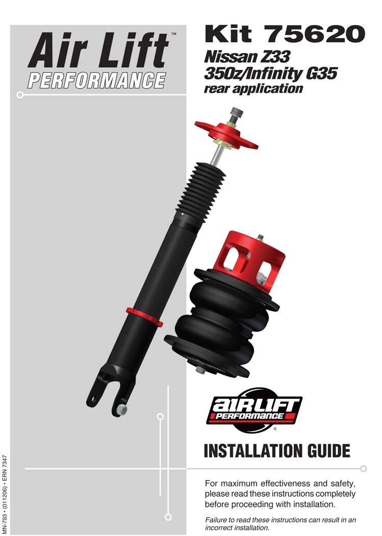
18 2 MN-793
19 TABLE OF CONTENTS Introduction Notation Explanation....2 Important Safety Notices...2 Installation Diagram Hardware List....3 Installing the Air Suspension Preparing the Vehicle....4 Stock Shock and Spring Removal....4 Air Suspension Installation....6 Damping Adjustment....9 Aligning the Vehicle....9 Before Operating Installation Checklist Post-installation checklist Product Use, Maintenance and Servicing Suggested Driving Air Pressure and Maximum Air Pressure Maintenance Guidelines Troubleshooting Guide Frequently Asked Questions Tuning the Air Pressure Checking for Leaks Fixing Leaks Warranty and Returns Policy Replacement Information Contact Information MN-793 1
20 Introduction Air Lift Performance The purpose of this publication is to assist with the installation, maintenance and troubleshooting of this Nissan/Infinity Performance suspension kit. It is important to read and understand the entire installation guide before beginning installation or performing any maintenance, service or repair. The information includes a hardware list, tool list, step-by-step installation information, maintenance tips, safety information and a troubleshooting guide. Air Lift Company reserves the right to make changes and improvements to its products and publications at any time. For the latest version of this manual, contact Air Lift Company at (800) or visit our website at NOTATION EXPLANATION Hazard notations appear in various locations in this publication. Information which is highlighted by one of these notations must be observed to help minimize risk of personal injury or possible improper installation which may render the vehicle unsafe. Notes are used to help emphasize areas of procedural importance and provide helpful suggestions. The following definitions explain the use of these notations as they appear throughout this guide. DANGER WARNING CAUTION NOTE INDICATES IMMEDIATE HAZARDS WHICH WILL RESULT IN SEVERE PERSONAL INJURY OR DEATH. INDICATES HAZARDS OR UNSAFE PRACTICES WHICH COULD RESULT IN SEVERE PERSONAL INJURY OR DEATH. INDICATES HAZARDS OR UNSAFE PRACTICES WHICH COULD RESULT IN DAMAGE TO THE MACHINE OR MINOR PERSONAL INJURY. Indicates a procedure, practice or hint which is important to highlight. IMPORTANT SAFETY NOTICES The installation of this kit does not alter the Gross Vehicle Weight Rating (GVWR) or payload of the vehicle. Check your vehicle s owner s manual and do not exceed the maximum load listed for your vehicle. Gross Vehicle Weight Rating: The maximum allowable weight of the fully loaded vehicle (including passengers and cargo). This number along with other weight limits, as well as tire, rim size and inflation pressure data is shown on the vehicle s Safety Compliance Certification Label. Payload: The combined, maximum allowable weight of cargo and passengers that the vehicle is designed to carry. Payload is GVWR minus the Base Curb Weight. WARNING CAUTION DO NOT INFLATE AIR SPRINGS WHILE OFF OF THE VEHICLE. DAMAGE TO ASSEMBLY MAY RESULT AND VOID WARRANTY. DO NOT WELD TO, OR MODIFY LIFESTYLE STRUTS/SHOCKS IN ANY WAY. DAMAGE TO UNIT MAY OCCUR AND WILL VOID WARRANTY. 2 MN-793
21 G F I J F H F G K Air Lift Performance Installation Diagram D E B o r C A D fig. 1 HARDWARE LIST Item Part # Description...Qty A Air Spring...2 B /8 MNPT X 1/4 PTC, C /8 MNPT-3/8 PTC, D Roll Plate... 4 E Spacer, Upper Air Spring... 2 F /8 Lock Washer... 8 G /8-24 X 3/4 Hex Bolt... 6 H /8-16 Nutsert... 2 I Spacer, Lower Centering... 2 J /8-16 X 1.5 Hex Cap Screw... 2 K Rear Shock, Nissan Z STOP! Missing or damaged parts? Call Air Lift customer service at (800) for a replacement part. MN-793 3

. fig.")

22 Installing the Air Suspension Air Lift Performance PREPARING THE VEHICLE 1. Elevate and support the vehicle with jack stands or a hoist at approved lifting points. 2. Remove the rear wheels (fig. 2). fig. 2 STOCK SHOCK AND SPRING REMOVAL 1. Support the hub assembly to prevent overextension of suspension components. 2. Remove the lower shock bolt from the lower control arm (figs. 3 & 4). fig. 3 fig. 4 4 MN-793
.")


23 3. Remove the two upper shock bracket bolts and remove the shock from the vehicle (figs. 5 & 6). fig. 5 fig nbolt the lower control arm from the hub and slowly lower the control arm down (fig. 7). 5. Remove the coil spring and rubber isolators from the spring seats. The conical upper spring isolator snaps into place and can be removed with a side-to-side motion (fig. 8). fig. 7 fig. 8 MN-793 5
 hole through the center of the lower control arm spring seat (fig. 9). fig. 9 2.")
. Place the bracket against the spring seat and mark the center location. Drill a hole 17/32 (.")

24 AIR SUSPENSION INSTALLATION 1. Using the supplied centering washer as a template, drill a 13/32 (.406 diameter) hole through the center of the lower control arm spring seat (fig. 9). fig To install the nutsert in the upper spring seat, the upper bracket can be used as a template to center the air spring location (fig. 10). Place the bracket against the spring seat and mark the center location. Drill a hole 17/32 (.531 diameter) through the spring seat. fig Assemble the nutsert and tool bolt and insert the assembly into the drilled hole. While holding the nutsert spacer in place, tighten the tool bolt until the nutsert is fully seated and locked in place (figs. 11, 12 & 13). fig MN-793


")


25 fig. 12 fig Reinstall the lower control arm to the hub. Do not torque at this time. 5. Attach the air spring upper bracket to the upper spring seat (fig. 14). Torque the upper bracket bolt (J with lock washer F) to 20Nm (15 ft-lbs). fig Apply the roll plate underneath the air spring. Lift the upper control arm and attach the air spring assembly to the control arm with the centering spacer (I), bolt (G) and lock washer (F) through the previously drilled hole. Torque to 20 Nm (15 ft-lbs). (figs. 15 & 16) fig. 15 fig. 16 MN-793 7

26 7. Insert the shock assembly into the shock tower and attach the upper bracket to the chassis (fig. 17). Torque the upper bracket nuts to 28 Nm (21 ft-lbs). fig Attach the shock fork to the lower transverse link. Do not torque the attaching bolt at this time. 9. With the suspension fully compressed, take a measurement from the fender to some reference point typically the center of the axle. Record this measurement as Max Compression. 10. Cycle the suspension to Max Extension and record the measurement from the same reference points. 11. Take the difference between the two numbers and divide by two. Add that value to the original Max Compression number. Set the suspension to this point. This position gives 50% stroke in either position and is a starting point for ride height. 12. With the suspension at this position, torque the lower shock bolt and upper and lower control arm bolts to manufacturer s specifications (Table 1). Formula for calculating ride height (fig. 18): Step 1: ME - MC X Step 2: X 2 = Y Step 3: Y + MC Z Answer: fig. 18 Z = DESIGN HEIGHT Table 1 Torque Specifications Location Nm ft. lbs. Upper bracket to chassis Lower air spring attachment bolt Lower control arm to hub Lower control arm to sub-frame Upper control arm to sub-frame Trailing link to chassis Trailing link to sub-frame Transverse link to hub Transverse link to sub-frame Shock lower mount to hub Shock upper mount to chassis Wheels Table 1 8 MN-793

27 DAMPING ADJUSTMENT The shocks in this kit have 30 settings, or clicks, of adjustable compression and rebound damping characteristics. Damping is changed through the shock rod using the supplied adjuster or a 3mm allen wrench. Turn the adjuster clockwise and the damping settings are hardened. Turn the adjuster counterclockwise and the damping is softened. Each shock is preset to -12 clicks. This means that the shock is adjusted 12 clicks away from full stiff. Counting down from full stiff is the preferred method of keeping track/setting of damping. This setting was developed on a 2007 Nissan 350z NISMO and may need to be adjusted to different vehicles and driving characteristics. fig. 19 fig. 20 NOTE ALIGNING THE VEHICLE 1. Using the control system, set the vehicle height to the new custom ride height. 2. If the custom ride height is lower than stock, we recommend loosening all pivot points (bolts, nuts) on any control arm, strut arm or radius rod that contains bushings (fig. 7). Once they have been loosened, re-torque to stock specifications. It may be necessary to cycle the suspension to loosen the bushing up from its mount. This will help re-orient the bushing at its new position based on the custom ride height. MN-793 9
28 Before Operating CAUTION MAKE SURE THE FRONT WHEELS ARE STRAIGHT WHEN DEFLATING AND REINFLATING AIR BAGS. 1. Inflate and deflate the system (do not exceed 125 PSI) to check for clearance or binding issues. With the air springs deflated, check clearances on everything so as not to pinch brake lines, vent tubes, etc. Clear lines if necessary. 2. Inflate the air springs to 75PSI - 90PSI and check all connections for leaks. 3. Air Lift part #27669 or #27671, AutoPilot V2 Air Management System, is highly recommended for this product. 4. Please continue by reading the Product Use, Maintenance and Servicing section. INSTALLATION CHECKLIST Clearance test Inflate the air springs to PSI and make sure there is at least ½ clearance from anything that might rub against each sleeve. Be sure to check the tire, brake drum, frame, shock absorbers and brake cables. Leak test before road test Inflate the air springs to 75PSI - 90PSI and check all connections for leaks. All leaks must be eliminated before the vehicle is road tested. Heat test Be sure there is sufficient clearance from heat sources, at least 6 for air springs and air lines. If a heat shield was included in the kit, install it. If there is no heat shield, but one is required, call Air Lift customer service at (800) Fastener test Recheck all bolts for proper torque. Road test The vehicle should be road tested after the preceding tests. Inflate the springs to recommended driving pressures. Drive the vehicle 10 miles and recheck for clearance, loose fasteners and air leaks. Operating instructions If professionally installed, the installer should review the operating instructions with the owner. Be sure to provide the owner with all of the paperwork that came with the kit. Technician s Signature Date POST-INSTALLATION CHECKLIST Overnight leak down test Recheck air pressure after the vehicle has been used for 24 hours. If the pressure has dropped more than 5 PSI, then there is a leak that must be fixed. Either fix the leak yourself or return to the installer for service. Air pressure requirements I understand the air pressure requirements of my air spring system. Regardless of load, the air pressure should always be adjusted to maintain adequate ride height at all times while driving. Thirty day or 500 mile test I understand that I must recheck the air spring system after 30 days or 500 miles, whichever comes first. If any part shows signs of rubbing or abrasion, the source should be identified and moved, if possible. If it is not possible to relocate the cause of the abrasion, the air spring may need to be remounted. If professionally installed, the installer should be consulted. Check all fasteners for tightness. 10 MN-793
29 Product Use, Maintenance and Servicing Suggested Driving Air Pressure Maximum Air Pressure 50 PSI 125 PSI FAILURE TO MAINTAIN ADEQUATE MINIMUM PRESSURE (OR PRESSURE PROPORTIONAL TO LOAD) WILL RESULT IN BOTTOMING OUT, OVER-EXTENSION OR RUBBING AGAINST ANOTHER COMPONENT AND WILL VOID THE WARRANTY. MAINTENANCE GUIDELINES NOTE MN-793 CAUTION By following these steps, vehicle owners will obtain the longest life and best results from their air spring. 1. Check the air pressure before driving. 2. Never inflate beyond 125 PSI. 3. If you develop an air leak in the system, use a soapy water solution to check all air line connections, before deflating and removing the spring. 4. When increasing load, always adjust the air pressure to maintain normal ride height. Increase or decrease pressure from the system as necessary to attain normal ride height for optimal ride and handling. Remember that loads carried behind the axle (including tongue loads) require more leveling force (pressure) than those carried directly over the axle. FOR YOUR SAFETY AND TO PREVENT DAMAGE TO YOUR VEHICLE, DO NOT EXCEED MAXIMUM GROSS VEHICLE WEIGHT RATING (GVWR), AS INDICATED BY THE VEHICLE MANUFACTURER. ALTHOUGH YOUR AIR SPRINGS ARE RATED AT A MAXIMUM INFLATION PRESSURE OF 125 PSI, THE AIR PRESSURE ACTUALLY NEEDED IS DEPENDENT ON YOUR LOAD. 5. Always add air to the springs in small quantities, checking the pressure frequently. Sleeves require less air volume than a tire and inflate quickly. 6. Should it become necessary to raise the vehicle by the frame, make sure the control system is turned off before lifting. TROUBLESHOOTING GUIDE 1. Leak test the air line connections, the threaded connection into the air spring, and all fittings in the control system. 2. Inspect the air lines to be sure none are pinched. Tie straps may be too tight. Loosen or replace the strap and replace leaking components. 3. Inspect the air line for holes and cracks. Replace as needed. 4. Look for a kink or fold in the air line. Reroute as needed. If the preceding steps do not solve the problem, it is possibly caused by a failed air spring either a factory defect or an operating problem. Please call Air Lift at (800) for assistance. FREQUENTLY ASKED QUESTIONS Q. Will installing air springs increase the weight ratings of a vehicle? No. Adding air springs will not change the weight ratings (GAWR, GCWR and/or GVWR) of a vehicle. Exceeding the GVWR is dangerous and voids the Air Lift warranty. Q. How long should air springs last? If the air springs are properly installed and maintained they can last indefinitely. 11
30 Q. Will raising the vehicle on a hoist for service work damage the air springs? No. The vehicle can be lifted on a hoist for short-term service work such as tire rotation or oil changes. However, if the vehicle will be on the hoist for a prolonged period of time, support the axle with jack stands in order to take the tension off of the air springs. TUNING THE AIR PRESSURE Pressure determination comes down to three things level vehicle, ride comfort, and stability. 1. Level vehicle If the vehicle s headlights are shining into the trees or the vehicle is leaning to one side, then it is not level. Raise the air pressure to correct either of these problems and level the vehicle. 2. Ride comfort If the vehicle has a rough or harsh ride it may be due to either too much pressure or not enough. Try different pressures to determine the best ride comfort. See Air Lift suggested driving air pressure. 3. Stability Stability translates into safety and should be the priority, meaning the driver may need to sacrifice a perfectly level and comfortable ride. Stability issues include roll control, bounce, dive during braking and sponginess. Tuning out these problems usually requires additional air pressure, strut damping, or both. CHECKING FOR LEAKS 1. Inflate the air spring to 80 PSI. 2. Spray all connections and the inflation valves with a solution of 1/5 liquid dish soap and 4/5 water. Spot leaks easily by looking for bubbles in the soapy water. 3. After the test, deflate the springs to the minimum pressure required to restore the system to normal ride height. 4. Check the air pressure again after 24 hours. A 2-4 PSI loss after initial installation is normal. Retest for leaks if the loss is more than 5 lbs. FIXING LEAKS 1. If there is a problem with a swivel fitting: a. Check the air line connection by deflating the spring and removing the line by pulling the collar against the fitting and pulling firmly on the air line. Trim 1 off the end of the air line. Be sure the cut is clean and square (see fig. 21). Reinsert the air line into the push-to-connect fitting. b. Check the threaded connection by tightening the swivel fitting another ½ turn. If it still leaks, deflate the air spring, remove the fitting, and re-coat the threads with thread sealant. Reinstall by hand tightening as much as possible and then use a wrench for an additional two turns. 2. If the preceding steps have not resolved the problem, call Air Lift customer service at (800) fig MN-793
31 Warranty and Returns Policy Air Lift Company warrants its performance products for one year to the original purchaser against manufacturing defects one year from the date of purchase when used on cars and trucks as specified under normal operating conditions. The warranty does not apply to products that have been improperly applied, improperly installed, or which have not been maintained in accordance with installation instructions furnished with all products. The consumer will be responsible for removing (labor charges) the defective product from the vehicle and returning it, transportation costs prepaid, to the dealer from which it was purchased or to Air Lift Company for verification. Air Lift will repair or replace, at its option, defective products or components. A minimum $10.00 shipping and handling charge will apply to all warranty claims. Before returning any defective product, you must call Air Lift at (800) in the U.S. and Canada (elsewhere, (517) ) for a Returned Materials Authorization (RMA) number. Returns to Air Lift can be sent to: Air Lift Company 2727 Snow Road Lansing, MI Product failures resulting from abnormal use or misuse are excluded from this warranty. The loss of use of the product, loss of time, inconvenience, commercial loss or consequential damages is not covered. The consumer is responsible for installation/reinstallation (labor charges) of the product. Air Lift Company reserves the right to change the design of any product without assuming any obligation to modify any product previously manufactured. This warranty gives you specific legal rights and you may also have other rights that may vary from state-to-state. Some states do not allow limitations on how long an implied warranty lasts or allow the exclusion or limitation of incidental or consequential damages. The above limitation or exclusion may not apply to you. There are no warranties, expressed or implied including any implied warranties of merchantability and fitness, which extend beyond this warranty period. There are no warranties that extend beyond the description on the face hereof. Seller disclaims the implied warranty of merchantability. (Dated proof of purchase required.) Replacement Information If you need replacement parts, contact the local dealer or call Air Lift customer service at (800) Most parts are immediately available and can be shipped the same day. Contact Air Lift Company customer service at (800) first if: Parts are missing from the kit. Need technical assistance on installation or operation. Broken or defective parts in the kit. Wrong parts in the kit. Have a warranty claim or question. Contact the retailer where the kit was purchased: If it is necessary to return or exchange the kit for any reason. If there is a problem with shipping if shipped from the retailer. If there is a problem with the price. Contact Information If you have any questions, comments or need technical assistance contact our customer service department by calling (800) , Monday through Friday, 8 a.m. to 8 p.m. Eastern Time. For calls from outside the USA or Canada, our local number is (517) You may also contact customer service anytime by at techsupport@airliftperformance.com. For inquiries by mail, our address is PO Box 80167, Lansing, MI Our shipping address for returns is 2727 Snow Road, Lansing, MI You may also contact our sales team anytime by at sales@airliftperformance.com or on the web at MN
32 Need Help? Contact our customer service department by calling (800) , Monday through Friday, 8 a.m. to 8 p.m. Eastern Time. For calls from outside the USA or Canada, our local number is (517) Thank you for purchasing Air Lift Performance products! Air Lift Company 2727 Snow Road Lansing, MI or PO Box Lansing, MI Toll Free (800) Local (517) Fax (517) Printed in the USA


33 Air Lift PERFORMANCE Kits and MN-726 (031107) ECR 7119 INSTALLATION GUIDE For maximum effectiveness and safety, please read these instructions completely before proceeding with installation. Failure to read these instructions can result in an incorrect installation.
34
35 TABLE OF CONTENTS Introduction... 2 Important Safety Notice...2 Notation Explanation...2 Installation Diagram...3 Hardware List....4 Installing the Air Management System...4 Assembling the Air Tank...4 Recommended Compressor Locations...5 Attaching the Compressor...5 Wiring the System...5 Attaching the Air Lines Assembling the Pneumatic Paddle Switches...6 Troubleshooting Guide....6 Tuning the Air Pressure...6 Checking for Leaks...7 Fixing Leaks....7 Warranty and Returns Policy...8 Replacement Information...9 Contact Information...9 1
36 Introduction Air Lift Performance The purpose of this publication is to assist with the installation, maintenance and troubleshooting of the Air Management System. It is important to read and understand the entire installation guide before beginning installation or performing any maintenance, service or repair. The information here includes a hardware list, tool list, step-by-step installation information, maintenance guidelines and troubleshooting guide. Air Lift Company reserves the right to make changes and improvements to its products and publications at any time. For the latest version of this manual, contact Air Lift Company at (800) or visit our website at IMPORTANT SAFETY NOTICE The installation of this kit does not alter the ross ehicle Weight Rating ( WR) or payload of the vehicle. Check your vehicle s owner s manual and do not exceed the maximum load listed for your vehicle. Gross Vehicle Weight Rating: The maximum allowable weight of the fully loaded vehicle (including passengers and cargo). This number along with other weight limits, as well as tire, rim size and inflation pressure data is shown on the vehicle s Safety Compliance Certification Label. Payload: The combined, maximum allowable weight of cargo and passengers that the vehicle is designed to carry. Payload is WR minus the Base Curb Weight. NOTATION EXPLANATION Hazard notations appear in various locations in this publication. Information which is highlighted by one of these notations must be observed to help minimize risk of personal injury or possible improper installation which may render the vehicle unsafe. Notes are used to help emphasize areas of procedural importance and provide helpful suggestions. The following definitions explain the use of these notations as they appear throughout this guide. DANGER WARNING CAUTION NOTE INDICATES IMMEDIATE HA ARDS WHICH WILL RES LT IN SE ERE PERSONAL IN R OR DEATH. INDICATES HA ARDS OR NSAFE PRACTICES WHICH CO LD RES LT IN SE ERE PERSONAL IN R OR DEATH. INDICATES HA ARDS OR NSAFE PRACTICES WHICH CO LD RES LT IN DAMA E TO THE MACHINE OR MINOR PERSONAL IN R. Indicates a procedure, practice or hint which is important to highlight. 2 MN-726
37 Installation Diagram MM S NN MM AA EE AA X or Y CC Z DD 30 AMP Z Existing Fuse KK T B2 (5 Gal. Tank) LL P W U S R B1 (2 Gal. Tank) Q O V E E A BB Ground D C T C D Splice into keyed on ignition wire. L Connector Power (Red) Inside View of Connector J I Ground M M N F G JJ JJ JJ JJ PP DEL SUP Air Bags are for Reference Only Not included with air management system. HH OO fig. 1 II MN-726 3
38 Hardware List Item Part No. Description Quantity Quantity A iair Compressor 1 1 B allon Air Tank 1 1 B allon Tank 1 C /8 Flat Washer 8 8 D /8-16 x 1.25 Bolt 4 4 E /8 Nyloc Nut 4 4 F Dual Needle auge /4 Air Line 80 ft. 60 ft. H /2 Self-Tapping Screw 3 3 I auge Ring Terminal uick Splice Butt Connector 2 2 L auge Red Wire 8 ft. 8 ft. M auge Black Wire 8 ft. 8 ft. N auge Female Terminal 4 2 O /8 Street Tee 1 1 P /8 FNPT x 3/8 MNPT Bushing /4 FNPT x 1/8 FNPT Bushing 1 1 R /4 MNPT x 1/8 FNPT Bushing 1 1 S Inflation alve 1/8 MNPT 1 1 T /4 MNPT Drain Cock 1 1 Air Lift Performance Item Part No. Description Plug /8 x 1/4 PTC Elbow W PSI Pressure Switch X Fuse Tap Mini Fuse Adapter auge Butt Connector AA auge Female Terminal BB /4 x 1 Self-Tapping Screw CC auge Red Wire DD Fuse Holder EE AMP Fuse Spade FF Thread Sealant Air Line Cutter HH Panel II Fitting Tee /2 Plug LL /4 x 1/2 Bushing MM /8 1/2 Bushing NN /8 x 1/2 Bushing OO /4 Stainless Steel Screws PP Paddle Switch Quantity ft STOP! Missing or damaged parts Call Air Lift customer service at (800) for a replacement part. Installing the Air Management System The following instructions correspond to Figure 1 on the previous page of this instruction manual. ASSEMBLING THE AIR TANK NOTE All fittings must be pre-coated with thread sealant. 1. Install a 1/8 bushing (P) to the top port of the street tee (O) and a 1/4 bushing ( ) to the other port. 2. Attach the pressure switch (W) to the 1/8 bushing previously installed onto the street tee. 3. Attach the street tee assembly to the end port of the air tank (B). 4. Install a drain cock (T) to the port that is at the base of the tank. NOTE If the tank is mounted with the feet up, the drain cock must be installed on the other side of the tank. The drain must always be installed in the port that is facing downward. 5. Install a 1/4 x 1/8 bushing (R) to the port that is facing upwards on the air tank. Attach an inflation valve (S) to the bushing. 6. Install an air fitting ( ) to the remaining end port of the air tank. 7. Install plugs ( ) to the two ports on the front of the air tank. 8 Find a suitable mounting location for the air tank and mount using the provided bolts (D), flat washers (C), and nyloc nuts (E). 4 MN-726
39 RECOMMENDED COMPRESSOR LOCATIONS Important LOCATE COMPRESSOR IN DR, PROTECTED AREA ON EHICLE. DIRECT SPLASH OR E CESSI E MOIST RE CAN DAMA E THE COMPRESSOR AND CA SE S STEM FAIL RE. Disclaimer: If you choose to mount the compressor outside the vehicle please keep in mind the compressor body must be shielded from direct splash and the intake should be snorkeled inside the vehicle. If the compressor does not include a remote mount air filter or if mounting the compressor outside the vehicle, make sure to orient the compressor intake filter so that all moisture can easily drain. Please also remember... To avoid high heat environments To avoid mounting the compressor under the hood. To check to be sure the compressor harness 2 will reach the compressor and connect to harness 1. The compressor can be mounted in any position vertical, upside down, sideways, etc. (please refer to the instruction manual). ATTACHING THE COMPRESSOR 1. Find a suitable mounting location for the compressor and mount using the hardware included with the compressor. 2. Attach the leader hose from the compressor (A) to the 1/4 x 1/8 bushing previously attached to the street tee. WIRING THE SYSTEM 1. Attach the red power wire from the compressor to the pressure switch using the attached female terminal. 2. Attach the black ground wire to a suitable location on the frame of the vehicle using a self-tapping screw (BB). 3. Cut a length of red wire (L) long enough to go from the gauges to a keyed on ignition wire. Attach a female terminal (N) to one end of the wire. Attach this end to the gauge panel. uick splice the two gauge bulbs together. 4. Splice the remaining end of the red power wire to a keyed on ignition wire using the provided quick splice ( ). 5. Ground the gauges by attaching the black ground wire to a suitable location using the remaining self-tapping screw (H). 6. Cut a length of red wire (CC) to go between the pressure switch on the air tank to a fuse holder (DD). Attach the two together using a butt connector ( ). 7. Install a 30 AMP fuse into the fuse holder. 8. Cut another length of red wire (CC) long enough to go between the fuse holder and the fuse box. Attach a female terminal (AA) to one end of the wire and attach the remaining end to the fuse holder using a butt connector ( ). Choose a key-on circuit. MN-726 5
40 9. Attach the female terminal to either the fuse tap ( ) or mini fuse adapter ( ). Attach this to the fuse panel. ATTACHING THE AIR LINES CAUTION WHEN C TTIN OR TRIMMIN THE AIR LINE, SE A HOSE C TTER ( ), A RA OR BLADE OR A SHARP NIFE. A CLEAN, S ARE C T WILL ENS RE A AINST LEA S. DO NOT SE WIRE C TTERS OR SCISSORS TO C T THE AIR LINE. THESE TOOLS MA FLATTEN OR CRIMP THE AIR LINE, CA SIN IT TO LEA (SEE FI. 2). 1. Run a length of air line ( ) from the air fitting on the compressor to the end of the switch cluster. 2. Run a length of air line from the remaining air fittings on the switch to its respective air spring. 3. Repeat step 2 for the remaining air fitting and air spring. 4. se a tee and connect into each one of the air spring lines to connect to it s respective gauge port. 5. Test and make sure that the switches operate the appropriate air springs. ASSEMBLING THE PNEUMATIC PADDLE SWITCHES 1. Snap all 4 switches into the panel so that from the back they are all oriented the same way ( ou may select a different location for switches. They do not need to be used with supplied panel). 2. Cut 6 pieces of hose the same length (approximately 3 6). 3. Push 4 of these hoses onto the S P port. Attach the Fittings as shown in fig. 1. Troubleshooting Guide 1. Leak test the air line connections, the threaded connection into the air spring, and all fittings in the control system. 2. Inspect the air lines to be sure none are pinched. Tie straps may be too tight. Loosen or replace the strap and replace leaking components. 3. Inspect the air line for holes and cracks. Replace as needed. 4. Look for a kink or fold in the air line. Reroute as needed. If the preceding steps do not solve the problem, it is possibly caused by a failed air spring either a factory defect or an operating problem. Please call Air Lift at (800) for assistance. Tuning the Air Pressure Pressure determination comes down to three things level vehicle, ride comfort, and stability. 1. Level vehicle If the vehicle s headlights are shining into the trees or the vehicle is leaning to one side, then it is not level. Raise the air pressure to correct either of these problems and level 6 MN-726
Air Lift. Kit PERFORMANCE INSTALLATION GUIDE. Nissan Z33 350z & Infiniti G35. Front Application (except AWD)
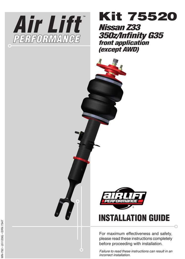
") Air Lift PERFORMANCE Kit 75520 Nissan Z33 350z & Infiniti G35 Front Application (except AWD) MN-792 (031403) ECR 7931 INSTALLATION GUIDE For maximum effectiveness and safety, please read these instructions
Air Lift PERFORMANCE Kit 75520 Nissan Z33 350z & Infiniti G35 Front Application (except AWD) MN-792 (031403) ECR 7931 INSTALLATION GUIDE For maximum effectiveness and safety, please read these instructions
Air Lift Performance 2 MN-805
 2 MN-805 TABLE OF CONTENTS Introduction.... 2 Notation Explanation....2 Important Safety Notices...2 Installation Diagram.... 3 Hardware List....3 Tools List....3 Installing the Air Suspension.... 4 Preparing
Introduction Important Safety Notice...2 Notation Explanation...2. Hardware List...4. Attaching the Compressor...4. Wiring the System...
 LifeSTYLE Kits 27665/27666 Cover illustration may not depict actual kit. MN-726 (02002) ECR 684 INSTALLATION GUIDE For maximum effectiveness and safety, please read these instructions completely before
Air Lift Performance 2 MN-896
 2 MN-896 TABLE OF CONTENTS Introduction....2 Notation Explanation...2 Important Safety Notices....2 Installation Diagram...3 Hardware List...3 Installing the Air Suspension.... 4 Preparing the Vehicle...4
Air Lift. Kit Ford Mustang (S-197) Track Pack Front Application PERFORMANCE INSTALLATION GUIDE
 Track Pack Front Application PERFORMANCE INSTALLATION GUIDE") Air Lift PERFORMANCE Kit 75523 Ford Mustang (S-197) Track Pack Front Application MN-813 (021402) ECR 7920 INSTALLATION GUIDE For maximum effectiveness and safety, please read these instructions completely
Air Lift PERFORMANCE Kit 75523 Ford Mustang (S-197) Track Pack Front Application MN-813 (021402) ECR 7920 INSTALLATION GUIDE For maximum effectiveness and safety, please read these instructions completely
Air Lift Performance 2 MN-925
 2 MN-925 TABLE OF CONTENTS Introduction....2 Notation Explanation...2 Important Safety Notices....2 Installation Diagram...3 Hardware List...3 Installing the Air Suspension....4 Preparing the Vehicle...4
Air Lift. Kits & PERFORMANCE INSTALLATION GUIDE. BMW E30 and E36/5/7/8 Compact. Rear Application
 Air Lift PERFORMANCE Kits 75673 & 78615 BMW E30 and E36/5/7/8 Compact Rear Application MN-889 (011406) ERN 7645 IMPORTANT: KIT 78615 DOES NOT COME WITH REAR SHOCKS. INSTALLATION GUIDE For maximum effectiveness
Kit INSTALLATION GUIDE. Mitsubishi EVO X Rear Application CAUTION
 Kit 78630 Mitsubishi EVO X Rear Application CAUTION READ PAGE 11 BEFORE INSTALLATION (021602) ECR 8402 INSTALLATION GUIDE For maximum effectiveness and safety, please read these instructions completely
Air Lift. Kit Dodge Charger, Challenger, 300C, and Magnum PERFORMANCE INSTALLATION GUIDE. (includes SRT 8 models, excludes AWD models)
") Air Lift PERFORMANCE Kit 75595 Dodge Charger, Challenger, 300C, and Magnum (includes SRT 8 models, excludes AWD models) MN-661 (031111) ECR 7189 INSTALLATION GUIDE For maximum effectiveness and safety,
Air Lift PERFORMANCE Kit 75595 Dodge Charger, Challenger, 300C, and Magnum (includes SRT 8 models, excludes AWD models) MN-661 (031111) ECR 7189 INSTALLATION GUIDE For maximum effectiveness and safety,
Air Lift. Kit MINI Cooper R50/52/53 PERFORMANCE INSTALLATION GUIDE. Rear Application CAUTION
 Air Lift PERFORMANCE Kit 78604 MINI Cooper R50/52/53 Rear Application CAUTION SEE PAGE 12 BEFORE BEGINNNING INSTALLATION (011505) ERN 7699 INSTALLATION GUIDE For maximum effectiveness and safety, please
Air Lift. Kit PERFORMANCE INSTALLATION GUIDE. Chevy Cobalt, Chevy HHR. front application
 Air Lift PERFORMANCE Kit 75594 Chevy Cobalt, Chevy HHR front application MN-644 (031111) ECR 7189 INSTALLATION GUIDE For maximum effectiveness and safety, please read these instructions completely before
Air Lift. Kit Honda Accord (8th GEN) Acura TL & TSX PERFORMANCE INSTALLATION GUIDE. Front Application CAUTION
 Acura TL & TSX PERFORMANCE INSTALLATION GUIDE. Front Application CAUTION") Air Lift PERFORMANCE Kit 78520 Honda Accord (8th GEN) Acura TL & TSX Front Application CAUTION READ PAGE 8 BEFORE INSTALLATION MN-935 (021503) ECR 8209 INSTALLATION GUIDE For maximum effectiveness and
Air Lift PERFORMANCE Kit 78520 Honda Accord (8th GEN) Acura TL & TSX Front Application CAUTION READ PAGE 8 BEFORE INSTALLATION MN-935 (021503) ECR 8209 INSTALLATION GUIDE For maximum effectiveness and
Air Lift. Kit PERFORMANCE INSTALLATION GUIDE. Audi A6 C5 Platform. Front Application
 Air Lift PERFORMANCE Kit 75528 Audi A6 C5 Platform Front Application MN-915 (011311) ERN 7602 INSTALLATION GUIDE For maximum effectiveness and safety, please read these instructions completely before proceeding
Air Lift Performance 2 MN-886
 2 MN-886 TABLE OF CONTENTS Introduction....2 Notation Explanation...2 Important Safety Notices....2 Installation Diagram...3 Hardware List...3 Installing the Air Suspension....4 Preparing the Vehicle...4
Air Lift Performance 2 MN-903
 2 MN-903 TABLE OF CONTENTS Introduction....2 Notation Explanation... 2 Important Safety Notices.... 2 Installation Diagram...3 Hardware List... 3 Installing the Air Suspension....4 Preparing the Vehicle...
Air Lift Performance 2 MN-916
 2 MN-916 TABLE OF CONTENTS Introduction....2 Notation Explanation...2 Important Safety Notices....2 Installation Diagram...3 Hardware List...3 Installing the Air Suspension....4 Preparing the Vehicle...4
Air Lift. Kit Ford Mustang S550 PERFORMANCE INSTALLATION GUIDE. Rear Application
 Air Lift PERFORMANCE Kit 78621 Ford Mustang S550 Rear Application MN-938 (021505) ERN 8031 INSTALLATION GUIDE For maximum effectiveness and safety, please read these instructions completely before proceeding
Air Lift Performance 2 MN-904
 2 MN-904 TABLE OF CONTENTS Introduction....2 Notation Explanation... 2 Important Safety Notices.... 2 Installation Diagram...3 Hardware List... 3 Installing the Air Suspension....4 Preparing the Vehicle...
Air Lift. Kit Ford Mustang S550 PERFORMANCE INSTALLATION GUIDE. Front Application
 Air Lift PERFORMANCE Kit 78521 Ford Mustang S550 Front Application MN-937 (011504) ERN 8031 INSTALLATION GUIDE For maximum effectiveness and safety, please read these instructions completely before proceeding
Air Lift. Kit PERFORMANCE INSTALLATION GUIDE. Scion tc. front application
 Air Lift PERFORMANCE Kit 75587 Scion tc front application MN-716 (031111) ECR 7189 INSTALLATION GUIDE For maximum effectiveness and safety, please read these instructions completely before proceeding with
Air Lift Performance 2 MN-805
 2 MN-805 TABLE OF CONTENTS Introduction.... 2 Notation Explanation....2 Important Safety Notices...2 Installation Diagram... 3 Hardware List...3 Tools List....3 Installing the Air Suspension.... 4 Preparing
Air Lift. Kit Honda Civic (8th GEN) PERFORMANCE INSTALLATION GUIDE. Front Application
 PERFORMANCE INSTALLATION GUIDE. Front Application") Air Lift PERFORMANCE Kit 78524 Honda Civic (8th GEN) Front Application MN-950 (011503) ERN 8128 INSTALLATION GUIDE For maximum effectiveness and safety, please read these instructions completely before
Air Lift PERFORMANCE Kit 78524 Honda Civic (8th GEN) Front Application MN-950 (011503) ERN 8128 INSTALLATION GUIDE For maximum effectiveness and safety, please read these instructions completely before
Air Lift. Kit Ford Mustang (S-197) Track Pack Rear Application PERFORMANCE INSTALLATION GUIDE
 Track Pack Rear Application PERFORMANCE INSTALLATION GUIDE") Air Lift PERFORMANCE Kit 75623 Ford Mustang (S-197) Track Pack Rear Application MN-814 (011209) ERN 7403 INSTALLATION GUIDE For maximum effectiveness and safety, please read these instructions completely
Air Lift PERFORMANCE Kit 75623 Ford Mustang (S-197) Track Pack Rear Application MN-814 (011209) ERN 7403 INSTALLATION GUIDE For maximum effectiveness and safety, please read these instructions completely
Air Lift. Kit Volkswagen MKVII PERFORMANCE INSTALLATION GUIDE. Front Application
 Air Lift PERFORMANCE Kit 78522 Volkswagen MKVII Front Application (for vehicles with 55mm lower strut diameter) (011411) ERN 8035 INSTALLATION GUIDE For maximum effectiveness and safety, please read these
Air Lift. Kit Volkswagen MKV & MKVI PERFORMANCE INSTALLATION GUIDE. Independent Rear Application
 Air Lift PERFORMANCE Kit 75690 Volkswagen MKV & MKVI Independent Rear Application MN-809 (031303) ECR 7578 INSTALLATION GUIDE For maximum effectiveness and safety, please read these instructions completely
Air Lift Performance 2 MN-803
 2 MN-803 TABLE OF CONTENTS Introduction.... 2 Notation Explanation....2 Important Safety Notices...2 Installation Diagram.... 3 Hardware List....3 Tools List....3 Installing the Air Suspension.... 4 Preparing
Air Lift. Kit MK IV Platform Slam front application PERFORMANCE INSTALLATION GUIDE
 Air Lift PERFORMANCE Kit 75518 MK IV Platform Slam front application NOTE: FOR USE ON VEHICLES WITH FRAME C-NOTCH MODIFICATIONS ONLY. FRONT SWAY BAR MUST BE REMOVED. (021111) ECR 7189 INSTALLATION GUIDE
Air Lift. Kit Honda Accord (8th GEN) Acura TL & TSX PERFORMANCE INSTALLATION GUIDE. Rear Application
 Acura TL & TSX PERFORMANCE INSTALLATION GUIDE. Rear Application") Air Lift PERFORMANCE Kit 78620 Honda Accord (8th GEN) Acura TL & TSX Rear Application MN-936 (021503) ECR 8209 INSTALLATION GUIDE For maximum effectiveness and safety, please read these instructions completely
Air Lift PERFORMANCE Kit 78620 Honda Accord (8th GEN) Acura TL & TSX Rear Application MN-936 (021503) ECR 8209 INSTALLATION GUIDE For maximum effectiveness and safety, please read these instructions completely
Air Lift PERFORMANCE INSTALLATION GUIDE. Front Application for Subaru Impreza, WRX & STi. ( ): Kits & 75552
: Kits & 75552") Air Lift PERFORMANCE (2002-2007): Kits 75551 & 75552 (2008-2012): Kits 75554, 75556 Front Application for Subaru Impreza, WRX & STi MN-790 (021311) ERN 7445 INSTALLATION GUIDE For maximum effectiveness
Air Lift PERFORMANCE (2002-2007): Kits 75551 & 75552 (2008-2012): Kits 75554, 75556 Front Application for Subaru Impreza, WRX & STi MN-790 (021311) ERN 7445 INSTALLATION GUIDE For maximum effectiveness
Air Lift Performance 2 MN-886
 2 MN-886 TABLE OF CONTENTS Introduction....2 Notation Explanation...2 Important Safety Notices....2 Installation Diagram...3 Hardware List...3 Installing the Air Suspension....4 Preparing the Vehicle...4
Air Lift. Kit Honda Civic (9th GEN) PERFORMANCE INSTALLATION GUIDE. Front Application
 PERFORMANCE INSTALLATION GUIDE. Front Application") Air Lift PERFORMANCE Kit 78526 Honda Civic (9th GEN) Front Application MN-952 (011502) ERN 8121 INSTALLATION GUIDE For maximum effectiveness and safety, please read these instructions completely before
Air Lift PERFORMANCE Kit 78526 Honda Civic (9th GEN) Front Application MN-952 (011502) ERN 8121 INSTALLATION GUIDE For maximum effectiveness and safety, please read these instructions completely before
Air Lift Performance 2 MN-868
 2 MN-868 TABLE OF CONTENTS Introduction.... 2 Notation Explanation...2 Important Safety Notices....2 Installation Diagram.... 3 Hardware List....3 Tools List....3 Installing the Air Suspension.... 4 Preparing
Air Lift. Kit PERFORMANCE INSTALLATION GUIDE Scion xb
 Air Lift PERFORMANCE Kit 75599 2008 Scion xb MN-687 (031111) ECR 7189 INSTALLATION GUIDE For maximum effectiveness and safety, please read these instructions completely before proceeding with installation.
Air Lift. Kit PERFORMANCE INSTALLATION GUIDE Scion xb
 Air Lift PERFORMANCE Kit 75699 2008- Scion xb MN-689 (041108) ECR 7072 INSTALLATION GUIDE For maximum effectiveness and safety, please read these instructions completely before proceeding with installation.
Air Lift Performance 2 MN-792
 2 MN-792 TABLE OF CONTENTS Introduction.... 2 Notation Explanation....2 Important Safety Notices...2 Installation Diagram... 3 Hardware List...3 Installing the Air Suspension.... 4 Preparing the Vehicle...4
Air Lift Performance 2 MN-869
 2 MN-869 TABLE OF CONTENTS Introduction.... 2 Notation Explanation....2 Important Safety Notices...2 Installation Diagram.... 3 Hardware List....3 Installing the Air Suspension.... 4 Preparing the Stock
Air Lift. Kit PERFORMANCE INSTALLATION GUIDE. Audi A4/S4 Quattro B5 Platform front application
 Air Lift PERFORMANCE Kit 75555 Audi A4/S4 Quattro B5 Platform front application MN-766 (021402) ERN 8190 INSTALLATION GUIDE For maximum effectiveness and safety, please read these instructions completely
Air Lift. Kit Honda Prelude ( ) PERFORMANCE INSTALLATION GUIDE
 PERFORMANCE INSTALLATION GUIDE") Air Lift PERFORMANCE Kit 75532 Honda Prelude (1992-2001) Cover illustration may not depict actual kit. MN-542 (06708) ECR 6206 INSTALLATION GUIDE For maximum effectiveness and safety, please read these
Air Lift PERFORMANCE Kit 75532 Honda Prelude (1992-2001) Cover illustration may not depict actual kit. MN-542 (06708) ECR 6206 INSTALLATION GUIDE For maximum effectiveness and safety, please read these
Air Lift. Kit BMW E30 (excludes AWD and M3) Front Application PERFORMANCE INSTALLATION GUIDE
 Front Application PERFORMANCE INSTALLATION GUIDE") Air Lift PERFORMANCE Kit 75573 BMW E30 (excludes AWD and M3) Front Application MN-888 (011406) ERN 7645 INSTALLATION GUIDE For maximum effectiveness and safety, please read these instructions completely
Air Lift PERFORMANCE Kit 75573 BMW E30 (excludes AWD and M3) Front Application MN-888 (011406) ERN 7645 INSTALLATION GUIDE For maximum effectiveness and safety, please read these instructions completely
Air Lift. Kit & Universal Sleeve-Over-Shocks PERFORMANCE INSTALLATION GUIDE NOTE: THIS KIT IS SOLD WITHOUT A WARRANTY.
 Air Lift PERFORMANCE Kit 75566 & 75569 Universal Sleeve-Over-Shocks MN-749 (031111) ECR 7189 NOTE: THIS KIT IS SOLD WITHOUT A WARRANTY. INSTALLATION GUIDE For maximum effectiveness and safety, please read
Air Lift Performance 2 MN-915
 2 MN-915 TABLE OF CONTENTS Introduction....2 Notation Explanation...2 Important Safety Notices....2 Installation Diagram...3 Hardware List...3 Installing the Air Suspension....4 Preparing the Vehicle...4
Kit Nissan Z33 350z & Infiniti G35
 Kit 75520 Nissan Z33 350z & Infiniti G35 Front Application (except AWD) MN-792 (041707) ECR 8795 INSTALLATION GUIDE For maximum effectiveness and safety, please read these instructions completely before
Air Lift Performance 2 MN-903
 2 MN-903 TABLE OF CONTENTS Introduction....2 Notation Explanation... 2 Important Safety Notices.... 2 Installation Diagram...3 Hardware List... 3 Installing the Air Suspension....4 Preparing the Vehicle...
Air Lift. Kit BMW E30 (excludes AWD and M3) Front Application PERFORMANCE INSTALLATION GUIDE
 Front Application PERFORMANCE INSTALLATION GUIDE") Air Lift PERFORMANCE Kit 75573 BMW E30 (excludes AWD and M3) Front Application MN-888 (011406) ERN 7645 INSTALLATION GUIDE For maximum effectiveness and safety, please read these instructions completely
Air Lift PERFORMANCE Kit 75573 BMW E30 (excludes AWD and M3) Front Application MN-888 (011406) ERN 7645 INSTALLATION GUIDE For maximum effectiveness and safety, please read these instructions completely
Air Lift Performance 2 MN-919
 2 MN-919 TABLE OF CONTENTS Introduction....2 Notation Explanation...2 Important Safety Notices....2 Installation Diagram...3 Hardware List...3 Installing the Air Suspension....4 Preparing the Vehicle...4
LifeSTYLE. Kit InstallatIon GuIdE. Scion tc. rear application
 LifeSTYLE Kit 75687 Scion tc rear application MN-717 (01905) ERN 6606 InstallatIon GuIdE For maximum effectiveness and safety, please read these instructions completely before proceeding with installation.
Air Lift Performance 2 MN-919
 2 MN-919 TABLE OF CONTENTS Introduction....2 Notation Explanation...2 Important Safety Notices....2 Installation Diagram...3 Hardware List...3 Installing the Air Suspension....4 Preparing the Vehicle...4
Air Lift Performance 2 MN-818
 2 MN-818 TABLE OF CONTENTS Introduction.... 2 Notation Explanation...2 Important Safety Notices....2 Installation Diagram... 3 Hardware List...3 Installing the Air Suspension.... 4 Preparing the Vehicle...4
Air Lift Performance 2 MN-872
 2 MN-872 TABLE OF CONTENTS Introduction.... 2 Notation Explanation...2 Important Safety Notices....2 Installation Diagram.... 3 Hardware List....3 Installing the Air Suspension.... 4 Preparing the Vehicle....4
Air Lift. Kit BMW E30 (excludes AWD and M3) Front Application PERFORMANCE INSTALLATION GUIDE
 Front Application PERFORMANCE INSTALLATION GUIDE") Air Lift PERFORMANCE Kit 75573 BMW E30 (excludes AWD and M3) Front Application MN-888 (011406) ERN 7645 INSTALLATION GUIDE For maximum effectiveness and safety, please read these instructions completely
Air Lift PERFORMANCE Kit 75573 BMW E30 (excludes AWD and M3) Front Application MN-888 (011406) ERN 7645 INSTALLATION GUIDE For maximum effectiveness and safety, please read these instructions completely
Air Lift Performance 2 MN-874
 2 MN-874 TABLE OF CONTENTS Introduction.... 2 Notation Explanation...2 Important Safety Notices....2 Installation Diagram... 3 Hardware List...3 Installing the Air Suspension.... 4 Preparing the Vehicle...4
Air Lift. Kit Honda Civic (8th GEN) PERFORMANCE INSTALLATION GUIDE. Front Application
 PERFORMANCE INSTALLATION GUIDE. Front Application") Air Lift PERFORMANCE Kit 78524 Honda Civic (8th GEN) Front Application MN-950 (011503) ERN 8128 INSTALLATION GUIDE For maximum effectiveness and safety, please read these instructions completely before
Air Lift PERFORMANCE Kit 78524 Honda Civic (8th GEN) Front Application MN-950 (011503) ERN 8128 INSTALLATION GUIDE For maximum effectiveness and safety, please read these instructions completely before
Air Lift. Kit PERFORMANCE INSTALLATION GUIDE. Audi A4/S4 Quattro B5 Platform front application
 Air Lift PERFORMANCE Kit 75555 Audi A4/S4 Quattro B5 Platform front application MN-766 (011107) ERN 7105 INSTALLATION GUIDE For maximum effectiveness and safety, please read these instructions completely
Air Lift. Kit PERFORMANCE INSTALLATION GUIDE. Audi A4 B6/B7 Platform front application
 Air Lift PERFORMANCE Kit 75578 Audi A4 B6/B7 Platform front application MN-759 (011104) ERN 7059 INSTALLATION GUIDE For maximum effectiveness and safety, please read these instructions completely before
No INSTALLATION GUIDE. For maximum effectiveness and safety, please read these instructions completely before proceeding with installation.
 No. 81560 MN-360 (071009) ECR 6976 INSTALLATION GUIDE For maximum effectiveness and safety, please read these instructions completely before proceeding with installation. Failure to read these instructions
Air Lift Performance 2 MN-872
 2 MN-872 TABLE OF CONTENTS Introduction.... 2 Notation Explanation...2 Important Safety Notices....2 Installation Diagram... 3 Hardware List...3 Installing the Air Suspension.... 4 Preparing the Vehicle...4
Air Lift Performance 2 MN-803
 2 MN-803 TABLE OF CONTENTS Introduction.... 2 Notation Explanation....2 Important Safety Notices...2 Installation Diagram... 3 Hardware List...3 Tools List....3 Installing the Air Suspension.... 4 Preparing
Air Lift. Kit BMW E30 (excludes AWD and M3) Front Application PERFORMANCE INSTALLATION GUIDE
 Front Application PERFORMANCE INSTALLATION GUIDE") Air Lift PERFORMANCE Kit 75573 BMW E30 (excludes AWD and M3) Front Application MN-888 (011406) ERN 7645 INSTALLATION GUIDE For maximum effectiveness and safety, please read these instructions completely
Air Lift PERFORMANCE Kit 75573 BMW E30 (excludes AWD and M3) Front Application MN-888 (011406) ERN 7645 INSTALLATION GUIDE For maximum effectiveness and safety, please read these instructions completely
LifeSTYLE. Kit Installation GuidE. Audi A4 B6/B7 Platform. rear application
 LifeSTYLE Kit 75678 Audi A4 B6/B7 Platform rear application MN-760 (011104) ERN 7059 Installation GuidE For maximum effectiveness and safety, please read these instructions completely before proceeding
Air Lift. Kit PERFORMANCE INSTALLATION GUIDE. Audi A4/S4 Quattro B5 Platform front application
 Air Lift PERFORMANCE Kit 75555 Audi A4/S4 Quattro B5 Platform front application MN-766 (011107) ERN 7105 INSTALLATION GUIDE For maximum effectiveness and safety, please read these instructions completely
Kits & BMW E30 and E36/5/7/8 Compact
 Kits 75673 & 78615 BMW E30 and E36/5/7/8 Compact Rear Application MN-889 (021509) ECR 8326 IMPORTANT: KIT 78615 DOES NOT COME WITH REAR SHOCKS. INSTALLATION GUIDE For maximum effectiveness and safety,
Kit INSTALLATION GUIDE. 5 psi Low Pressure Sensor (Single Gauge)
") Kit 25592 5 psi Low Pressure Sensor (Single Gauge) MN-333 (141404) ECR 7953 INSTALLATION GUIDE For maximum effectiveness and safety, please read these instructions completely before proceeding with installation.
Kit 25592 5 psi Low Pressure Sensor (Single Gauge) MN-333 (141404) ECR 7953 INSTALLATION GUIDE For maximum effectiveness and safety, please read these instructions completely before proceeding with installation.
Kit INSTALLATION GUIDE. 5 psi Low Pressure Sensor (Single Gauge)
") Kit 25592 5 psi Low Pressure Sensor (Single Gauge) MN-333 (131107) ECR 7119 INSTALLATION GUIDE For maximum effectiveness and safety, please read these instructions completely before proceeding with installation.
Kit 25592 5 psi Low Pressure Sensor (Single Gauge) MN-333 (131107) ECR 7119 INSTALLATION GUIDE For maximum effectiveness and safety, please read these instructions completely before proceeding with installation.
Air Lift PERFORMANCE INSTALLATION GUIDE. Front Application for Subaru Impreza, WRX & STi. ( ): Kits & 75552
: Kits & 75552") Air Lift PERFORMANCE (2002-2007): Kits 75551 & 75552 (2008-2012): Kits 75554, 75556 Front Application for Subaru Impreza, WRX & STi MN-790 (021311) ERN 7445 INSTALLATION GUIDE For maximum effectiveness
Air Lift PERFORMANCE (2002-2007): Kits 75551 & 75552 (2008-2012): Kits 75554, 75556 Front Application for Subaru Impreza, WRX & STi MN-790 (021311) ERN 7445 INSTALLATION GUIDE For maximum effectiveness
Kit INSTALLATION GUIDE. For maximum effectiveness and safety, please read these instructions completely before proceeding with installation.
 Kit 80537 MN-613 (031707) ECR 8866 INSTALLATION GUIDE For maximum effectiveness and safety, please read these instructions completely before proceeding with installation. Failure to read these instructions
Kit INSTALLATION GUIDE. 160 psi Air Shock Controller
 Kit 25804 160 psi Air Shock Controller Cover image may not depict actual kit. MN-203 (121107) ECR 7119 INSTALLATION GUIDE For maximum effectiveness and safety, please read these instructions completely
Kit INSTALLATION GUIDE. Front Application. Scion xa & xb
 Kit 75572 Scion xa & xb Front Application MN-610 (101710) ECR 8900 INSTALLATION GUIDE For maximum effectiveness and safety, please read these instructions completely before proceeding with installation.
Air Lift. Kit PERFORMANCE INSTALLATION GUIDE. MKII-III Platform. front application
 Air Lift PERFORMANCE Kit 75583 MKII-III Platform front application MN-733 (021106) ECR 7094 INSTALLATION GUIDE For maximum effectiveness and safety, please read these instructions completely before proceeding
PERFORMANCE SUSPENSION PARTS
 PERFORMANCE SUSPENSION PARTS Introduction Air Lift Performance The purpose of this publication is to assist with the installation, maintenance and troubleshooting of this Lexus XE10 Performance kit. It
Kit INSTALLATION GUIDE. For maximum effectiveness and safety, please read these instructions completely before proceeding with installation.
 Kit 25801 MN-208 (121506) ECR 8243 INSTALLATION GUIDE For maximum effectiveness and safety, please read these instructions completely before proceeding with installation. Failure to read these instructions
Kit Nissan Z34 370z Infiniti G37
 Kit 75621 Nissan Z34 370z Infiniti G37 Rear Application (021510) ECR 8221 INSTALLATION GUIDE For maximum effectiveness and safety, please read these instructions completely before proceeding with installation.
Air Lift. Kits PERFORMANCE / /78637 BMW E36, E46 Chassis Rear Application (With and Without Shocks) INSTALLATION GUIDE
 INSTALLATION GUIDE") Air Lift PERFORMANCE Kits 75636/78636 75646/78637 BMW E36, E46 Chassis Rear Application (With and Without Shocks) INSTALLATION GUIDE PERFORMANCE SUSPENSION PARTS For maximum effectiveness and safety, please
Air Lift PERFORMANCE Kits 75636/78636 75646/78637 BMW E36, E46 Chassis Rear Application (With and Without Shocks) INSTALLATION GUIDE PERFORMANCE SUSPENSION PARTS For maximum effectiveness and safety, please
PERFORMANCE SUSPENSION PARTS
 PERFORMANCE SUSPENSION PARTS Introduction Air Lift Performance The purpose of this publication is to assist with the installation, maintenance and troubleshooting of this Audi A6 C5 Performance kit. It
Kit psi Low Pressure Sensor (Dual Gauge)
") Kit 25812 5 psi Low Pressure Sensor (Dual Gauge) MN-337 (111107) ECR 7119 INSTALLATION GUIDE For maximum effectiveness and safety, please read these instructions completely before proceeding with installation.
Kit 25812 5 psi Low Pressure Sensor (Dual Gauge) MN-337 (111107) ECR 7119 INSTALLATION GUIDE For maximum effectiveness and safety, please read these instructions completely before proceeding with installation.
Kit INSTALLATION GUIDE. For maximum effectiveness and safety, please read these instructions completely before proceeding with installation.
 Kit 60809 MN-639 (021707) ECR 8866 INSTALLATION GUIDE For maximum effectiveness and safety, please read these instructions completely before proceeding with installation. Failure to read these instructions
Air Lift. Kit PERFORMANCE INSTALLATION GUIDE. MK IV Platform. Slam Front Application
 Air Lift PERFORMANCE Kit 75518 MK IV Platform Slam Front Application NOTE: FOR USE ON VEHICLES WITH FRAME C-NOTCH MODIFICATIONS ONLY. FRONT SWAY BAR MUST BE REMOVED. MN-756 (031409) ECR 8044 INSTALLATION
9th Gen Honda Civic INSTALLATION GUIDE Civic, Civic Si Kit Civic Si Kit Front Application
 9th Gen Honda Civic 2012-15 Civic, 2012-13 Civic Si Kit 78526 2014+ Civic Si Kit 78556 Front Application INSTALLATION GUIDE For maximum effectiveness and safety, please read these instructions completely
Air Lift. Kit Ford Mustang SN95 PERFORMANCE INSTALLATION GUIDE. Rear Application
 Air Lift PERFORMANCE Kit 78619 Ford Mustang SN95 Rear Application INSTALLATION GUIDE PERFORMANCE SUSPENSION PARTS For maximum effectiveness and safety, please read these instructions completely before
Kit Hyundai Genesis Coupe
 Kit 78531 Hyundai Genesis Coupe Front Application MN-968 (011609) ERN 8124 INSTALLATION GUIDE For maximum effectiveness and safety, please read these instructions completely before proceeding with installation.
Kits and Single Gauge Analog Compressor Systems
 Kits 25850 and 25854 Single Gauge Analog Compressor Systems Kit #25850 with standard duty compressor Kit #25854 with heavy duty compressor MN-750 (061202) ECR 7259 INSTALLATION GUIDE For maximum effectiveness
Kits (53mm), (48.5mm)
, (48.5mm)") Kits 78570 (53mm), 78571 (48.5mm) Audi B9 Front Application MN-1073 (011808) ERN 8788 INSTALLATION GUIDE For maximum effectiveness and safety, please read these instructions completely before proceeding
Kits 78570 (53mm), 78571 (48.5mm) Audi B9 Front Application MN-1073 (011808) ERN 8788 INSTALLATION GUIDE For maximum effectiveness and safety, please read these instructions completely before proceeding
Kit INSTALLATION GUIDE Toyota Sequoia 4WD
 Kit 60826 2011 Toyota Sequoia 4WD MN-765 (011107) ERN 7109 INSTALLATION GUIDE For maximum effectiveness and safety, please read these instructions completely before proceeding with installation. Failure
Kit Lexus LS 400 (UCF10 and UCF20)
") Kit 78659 Lexus LS 400 (UCF10 and UCF20) Rear Application MN-1032 (011701) ERN 8585 INSTALLATION GUIDE For maximum effectiveness and safety, please read these instructions completely before proceeding
Kit 78659 Lexus LS 400 (UCF10 and UCF20) Rear Application MN-1032 (011701) ERN 8585 INSTALLATION GUIDE For maximum effectiveness and safety, please read these instructions completely before proceeding
Kit Honda S2000 (AP1/AP2)
") Kit 78649 Honda S2000 (AP1/AP2) Rear Application INSTALLATION GUIDE MN-1004 (011601) ERN 8181 See page 11 for important information about sleeve-style dampers before installation. For maximum effectiveness
Kit 78649 Honda S2000 (AP1/AP2) Rear Application INSTALLATION GUIDE MN-1004 (011601) ERN 8181 See page 11 for important information about sleeve-style dampers before installation. For maximum effectiveness
Air Lift. Kit Honda Civic (8th GEN) PERFORMANCE INSTALLATION GUIDE. Front Application
 PERFORMANCE INSTALLATION GUIDE. Front Application") Air Lift PERFORMANCE Kit 78524 Honda Civic (8th GEN) Front Application INSTALLATION GUIDE PERFORMANCE SUSPENSION PARTS For maximum effectiveness and safety, please read these instructions completely before
Air Lift PERFORMANCE Kit 78524 Honda Civic (8th GEN) Front Application INSTALLATION GUIDE PERFORMANCE SUSPENSION PARTS For maximum effectiveness and safety, please read these instructions completely before
Kit Honda S2000 (AP1/AP2)
") Kit 78549 Honda S2000 (AP1/AP2) Front Application INSTALLATION GUIDE (011601) ERN 8181 See page 12 for important information about sleeve-style dampers before installation. For maximum effectiveness and
Kit 78549 Honda S2000 (AP1/AP2) Front Application INSTALLATION GUIDE (011601) ERN 8181 See page 12 for important information about sleeve-style dampers before installation. For maximum effectiveness and
Air Lift MN-739
 Kit 60823 2008- Scion xb Cover illustration may not depict actual kit. MN-739 (011005) ERN 6893 INSTALLATION GUIDE For maximum effectiveness and safety, please read these instructions completely before
Kit INSTALLATION GUIDE. Dodge 1500 Pickup, 2 & 4WD
 Kit 60818 Dodge 1500 Pickup, 2 & 4WD MN-753 (011012) ECR 6902 INSTALLATION GUIDE For maximum effectiveness and safety, please read these instructions completely before proceeding with installation. Failure
Kit Lexus LS 400 (UCF10 and UCF20)
") Kit 78559 Lexus LS 400 (UCF10 and UCF20) Front Application MN-1031 (011701) ERN 8585 INSTALLATION GUIDE For maximum effectiveness and safety, please read these instructions completely before proceeding
Kit 78559 Lexus LS 400 (UCF10 and UCF20) Front Application MN-1031 (011701) ERN 8585 INSTALLATION GUIDE For maximum effectiveness and safety, please read these instructions completely before proceeding
Compressor Isolator Kit 50714
 Air Lift PERFORMANCE Compressor Isolator Kit 50714 MN-902 (011307) ERN 7261 Compressor not supplied with isolator kit. INSTALLATION GUIDE View AutoPilotV2 videos at: www.airliftperformance.com/video/ For
PERFORMANCE SUSPENSION PARTS
 PERFORMANCE SUSPENSION PARTS Introduction Air Lift Performance The purpose of this publication is to assist with the installation, maintenance and troubleshooting of this Chrysler LX, LD, LC Platform 300C,
Kit Chevrolet Camaro 5th GEN Track Pack Front Application
 Kit 78501 Chevrolet Camaro 5th GEN Track Pack Front Application MN-886 (011310) ERN 7694 INSTALLATION GUIDE For maximum effectiveness and safety, please read these instructions completely before proceeding
Air Lift. Kit PERFORMANCE INSTALLATION GUIDE. Scion tc. front application
 Air Lift PERFORMANCE Kit 75587 Scion tc front application MN-716 (031111) ECR 7189 INSTALLATION GUIDE For maximum effectiveness and safety, please read these instructions completely before proceeding with
Please read these instructions completely before proceeding with installation. Air Spring Kit Parts List L F. Figure 1
 Kits No. 59561 Please read these instructions completely before proceeding with installation by www.airliftcompany.com MN-629 (01504) NPR 5117 Air Spring Kit Parts List Item Description Quantity A Air
Kit 78631/ Hyundai Genesis Coupe
 Kit 78631/ 78632 Hyundai Genesis Coupe Rear Application (with and without shocks) (011609) ERN 8124 INSTALLATION GUIDE For maximum effectiveness and safety, please read these instructions completely before
Air Lift Kits 60741, Ford Mustang INSTALLATION GUIDE
 Air Lift 1000 Kits 60741, 60841 Ford Mustang Cover image may not depict actual kit. MN-720 (01909) ERN 6730 INSTALLATION GUIDE For maximum effectiveness and safety, please read these instructions completely
Please read these instructions completely before proceeding with the installation. Hardware Identification. (1) Barbed Tee. (6) Air Line Clamp
 Barbed Tee. (6) Air Line Clamp") by MN-446 (01007) ECN3102 Kit No. 60788 Please read these instructions completely before proceeding with the installation. Hardware Identification (1) Barbed Tee (4) Hex Nut (2) 5/16" Flat Washer (6) Air
by MN-446 (01007) ECN3102 Kit No. 60788 Please read these instructions completely before proceeding with the installation. Hardware Identification (1) Barbed Tee (4) Hex Nut (2) 5/16" Flat Washer (6) Air
Driver Side Shown P/N Figure 1
 P/N 59544 by MN-612 (05606) ECR 5714 Please read these instructions completely before proceeding with the installation. NOTE: Unbolt the lower bracket from the leaf spring if the vehicle is to be serviced
LifeSTYLE. Kit & InstallatIon GuIdE. Universal Bellow-Over-Strut. NOTE: This kit is sold without a warranty.
 LifeSTYLE Kit 75561 & 75562 Universal Bellow-Over-Strut MN-723 (01909) ECR 6695 NOTE: This kit is sold without a warranty. InstallatIon GuIdE For maximum effectiveness and safety, please read these instructions
Air Lift. Kit PERFORMANCE INSTALLATION GUIDE. MK V Platform. Slam front application
 Air Lift PERFORMANCE Kit 75582 MK V Platform Slam front application MN-712 (041111) ECR 7189 NOTE: FOR USE ON VEHICLES WITH FRAME C-NOTCH MODIFICATIONS ONLY. FRONT SWAY BAR MUST BE REMOVED. INSTALLATION