PRESSURE RELIEF VALVE
|
|
|
- Kristina Stokes
- 6 years ago
- Views:
Transcription

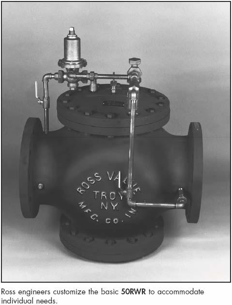
1 PRESSURE RELIEF VALVE INSTRUCTIONS Installation - Operation - Inspection - Maintenance 4" - 36" MODEL 50RWR Pressure Relief Valve Globe Flat Seat Style ROSS VALVE Mfg. Co., Inc. PO BOX 595, TROY, NY PHONE 518/ FAX 518/
2 INSTALLATION / START-UP (ROSS PISTON VALVE GLOBE OR ANGLE STYLE) Shipment: Prior to shipment, each valve is thoroughly tested and pre-adjusted at the factory to the expected field conditions. Any visible damage to the crate or packaging should be immediately brought to the attention of the shipping company and documented with photographs. Depending upon the valve size, external controls may be attached or in a separate box. The inlet of the main valve is identified with a metal tag. When controls are shipped separately, connections are tagged. Storage: If it is necessary to store the valve before installation, it should be protected from the elements. Inside storage is recommended. If this is not possible, the valve should be protected from dirt, heat, freezing, and direct sunlight. Installation: 1. Carefully remove all shipping materials and check the valve for any other foreign objects. 2. If possible, flush the line before inserting the valve. 3. The valve is tagged with a model and serial number. It is recommended that the serial number be noted in your records as this will be requested by the factory when any technical support or parts replacement is required. Valve serial number: L. 4. Place the valve in line with the flange marked INLET facing the high pressure or supply line. CAUTION: Do not obstruct the vent hole in the center of the bottom cap (#16 for Globe Body valves) or in the differential cylinder bracket (#27 for Angle Body valves). Allow enough clearance above the valve for removal of the stem assembly. 5. If external piping and controls are not attached to the valve when shipped, connect couplings identified with tags that are numbered. The arrow on the pilot valve body points in the direction of flow through the pilot valve. Flow is always away from the top cap of the main valve. The indicator rod (#20) shows the position of the main stem. 6. Attach gauge cocks to the back side of the valve. 7. Complete any necessary wiring on solenoid valves (if applicable). Start-Up: 1. Close the isolation valves (#18) in the control piping. 2. Open the main line gate valve (if installed) on the discharge/downstream side of the valve. 3. Slowly open the main line gate valve (if installed) on the inlet/upstream side of the valve. 4. Open the isolation valves (#18) in the control piping. 5. Loosening the union of the control piping on the top cap side of the speed control valve will help bleed air and give a positive indication when the operating chamber is full. It may be necessary to apply pressure to the valve indicator rod (if provided) with a wrench handle or block of wood until the valve operating chamber is pressurized. 6. No lubrication or adjustment to the valve is required or recommended. The valve has been thoroughly tested at the factory and set to the expected field conditions. ROSS VALVE MFG. CO., INC. 6 OAKWOOD AVE, TROY, NY TEL:

3

4 P.O. BOX 595, TROY, NEW YORK TEL FAX IMPORTANT To ensure proper operation of this relief valve, the controls of the valve must always be supplied with a positive pressure source. This positive pressure source is particularly important for installations where the relief or surge control valve is discharging to atmosphere or near atmospheric pressures. Low pressure conditions typically associated with a relief valve occur when the valve opens during start-up, test, or during a high pressure surge. Adequate testing should be performed on this valve and system to assure a low pressure condition will not occur during a surge condition. The system should be tested with the relief valve open. Supply pressure to the control piping should not fall below approximately 20 psi. With the valve open and discharging water, the valve should be able to close automatically as water is reintroduced into the controls. If the valve does not close, the controls should be piped to a positive pressure source. If a low pressure condition exists, the contractor or user should run a separate source of water pressure to the controls of the valve. A separate pressure source can typically be obtained from a header or similar location in the system where the line pressure is stable throughout the operation of the relief valve. ROSS VALVE MFG. CO., INC.
5 6 OAKWOOD AVENUE - TROY, NEW YORK, TEL. (518) POST OFFICE BOX TROY, NEW YORK, FAX (518) WEBSITE: sales@rossvalve.com 50RWR TJS 37 MODEL 50RWR RELIEF OR BACK PRESSURE SUSTAINING VALVE THIS PRINT CONTAINS CONFIDENTIAL INFORMATION WHICH IS THE PROPERTY OF ROSS VALVE BY ACCEPTING THIS INFORMATION THE BORROWER AGREES THAT IT WILL NOT BE USED FOR ANY PURPOSE OTHER THAN THAT WHICH IT IS LOANED. NOTE: The Ross Valve Mfg. Co., Inc., reserves the right to modify valve construction which will result in equal or superior performance to existing designs. These modifications may be made at any time and at the sole discretion of the manufacturer.
6 DIMENSIONS Globe Body Minimum Clearances Piston Valve Sizes: 4-48" Size (Inches) " 48" O P 4 1 / / / Note 1. Dimension O is clearance for removal of the top cap and piston for repacking the main valve. Additional working space for the convenience of the service man should be considered above as well as around the valve. 2. Dimension P as listed is the desirable clearance under the valve for removal of the STANDARD bottom cap. This dimension may be reduced to 1 inch for all valves on special applications. Note A. Do not obstruct vent hole located at the center of the bottom cap. B. Consideration should be given for installation of valves 14 or larger under manhole in the roof of the valve vault or for additional clearance above the valve since a mechanical hoist will probably be required for removal of the piston. An eye bolt or hook cast in the cover slab over the center of the valve is useful. C. If clearance under the valve is limited, dimensions O and P can be modified. Consult the factory concerning special applications. Factory: Telephone (518) ; Fax (518) EN - 15
7 The purpose of a pilot valve is to control the opening and closing of the main valve by trapping or releasing water from the main valve's "operating chamber" ("K" - the chamber above the main valve piston). The Model 50RWR Relief or Back Pressure Sustaining Pilot Valve uses this logic in order to control pressure upstream of the main valve. The pilot valve operates by creating a pressure balance across the diaphragms (#9). Pressure above the diaphragms is set by the adjusting screw (#2) acting on the springs (#6). Pressure beneath the diaphragms is exerted hydraulically via a separate sensing port directly under the diaphragms, from a remote inlet pressure source. When the pilot valve senses a low inlet pressure, the force of the springs (#6) causes the diaphragms (#9) and entire stem assembly to move down. This pushes the pilot seat packing (#19) into the seat, trapping water in the main valve operating chamber. This causes the piston of the main valve to close, resulting in an increase in the upstream pressure. Once the upstream pressure rises above the setting of the springs (#6), the hydraulic force overcomes the spring force and the stem assembly is pulled upwards by the attached diaphragms (#9). This causes the pilot seat packing (#19) to come off of its seat, releasing water from the main valve operating chamber. This causes the piston of the main valve to open, resulting in a decrease in the inlet pressure. This opening and closing sequence (commonly referred to as "throttling") is continuously taking place in order to control the inlet pressure of the main valve.
 from the top and passes out through the sides of the cylinder. 2.")
8 Sizes: ½ 1 Located: On any external piping Purpose: To protect external piping and control devices from fouling or damage from foreign particles Screen: Cylindrical Dutch weave stainless steel wire mesh Piping Connection: Standard pipe thread Operation 1. Water enters the cylindrical screen (#2) from the top and passes out through the sides of the cylinder. 2. Any particle too large to pass through.012 inch openings gets trapped in the cylinder, where, unless there is unusual turbulence, they settle at the bottom. Recommendation 1. Strainer should be blown down frequently to remove collected foreign material from the sediment chamber. 2. Strainer screen should be removed occasionally for inspection and thorough cleaning. PARTS FLOW 1. Body Bronze 2. Screen Stainless Steel 3. Cap Gasket Rubber 4. Cap Brass 5. Flushing Cock Brass Note 1. To clean without shutting down the line, open the flush cock (#5) in the bottom cap (#4) for several seconds. 2. To remove the screen (#2), which requires shutting down the line, unscrew the bottom cap assembly (#5). Model Number: 5F-2 Option Two strainers installed in parallel (with the appropriate isolation valves) to permit uninterrupted service while cleaning. Sizes: One size fits all piston valves Primarily Controlled By: Manually Adjusted Located: On external control circuit of the main valve Purpose: To limit flow in and out of the operating chamber Standard Shipped Adjustment: Course Needle: 5/6 to 2 turns off the seat Fine Needle: Based on individual specifications PARTS 1. Lock Brass 2. Cap Bronze 3. Cap Gasket Rubber 4. Needle Brass 5. Body Bronze Operation The simple construction reliably limits maximum flow through the external piping, depending on the position of the adjustable stem/needle (#4) relative to the seat. 1. When the needle (#4) is adjusted counter-clockwise to a raised position, a. More water can pass through the needle valve. b. Water enters (leaves) the operating chamber more quickly. c. The main valve piston moves up and down more quickly. 2. When the needle (#4) is adjusted clockwise to a lowered position, a. Less water can pass through the needle valve. b. Water enters (leaves) the operating chamber more slowly. c. The main valve piston moves up and down more slowly. Adjustment To adjust needle valve, which can be done without shutting down the main valve: 1. Remove the hex cap (#2) and lock(#1). 2. With a screw driver; a. Turn the needle (#4) counter-clockwise to raise it b. Turn the needle (#4) clockwise to lower it 3. Once the optimum position is determined, no further adjustment of the needle should be required. Note It is advisable to occasionally remove the cap (#2) and lock (#1) and change the position of the needle (#4) momentarily to insure against gradual plugging. Option Two separate needle valves on one main valve Provides independent control of opening and closing speeds.
9 ROSS GLOBE VALVE PREVENTIVE MAINTENANCE Intervals of inspection vary from valve to valve. Type of valve, quality of water being handled, rates of flow, operating pressures, and past maintenance practices all have a bearing on the length of service between overhauls. So some recommendation may guide the operator, we suggest periodic inspections in order to check for proper valve operating pressures, as well as any visual leaks. Should the operator encounter any external leakage, or find any abnormalities in the operating pressures resulting from the operation of the valve, the valve should be scheduled for service. EVERY TWO (2) MONTHS: 1. Flush the strainer via the flushing cock. 2. Flush the needle valve by turning then needle clockwise ½ turn, counter-clockwise 2 turns, then clockwise 1-1/2 turns to original setting. 3. Visually inspect for leaks around the indicator rod, bottom cap/differential vent hole, or pilot valves (hydraulic & /or solenoid). 4. Inspect drain line connection. EVERY FOUR (4) MONTHS: 1. Remove and inspect strainer screen. 2. Remove and inspect needle valve, being sure to take note of the needle position away from the seat (number of turns). 3. Same visual inspection as above. Important: Condition of the main valve packing can be accurately gauged by observing the leakage through the bottom vent hole C. Negligible leakage usually indicates serviceable packing. Lubrication: None Required. Spare Parts: None required, recommended, or supplied unless specified. Under normal operating conditions, no spare parts would be necessary within five (5) years of service. The standard repair kit for Ross valves are in stock at the factory, and available for immediate shipment upon receipt of order with valve serial number (located on metal tag pinned to the top cap of the main valve). ROSS VALVE MFG. CO., INC., TROY, NY PHONE FAX 518/
10 VALVE LOCATION/I.D. ROSS GLOBE VALVE INSPECTION - SERVICE RECORD SIZE MODEL SERIAL NO. VALVE - OPEN ~ CLOSED ~ INDICATOR ROD EXPOSED MAIN VALVE OPERATED MANUALLY YES ~...NO ~ OPERATING PRESSURES - INLET (SUPPLY) INCHES ABOVE STUFFING BOX CAP OUTLET (DOWNSTREAM) EXTERNAL LEAKS... NONE... SLIGHT... MAJOR...INDICATOR STUFFING BOX... ~... ~... ~...BOTTOM CAP VENT HOLE... ~... ~... ~...DIAPHRAGM VENT-HYDRAULIC PILOT... ~... ~... ~...SOLENOID PILOT EXHAUST PORT... ~... ~... ~ OTHER CONDITIONS STRAINER FLUSHED... YES ~... NO ~...SCREEN EXAMINED. YES ~... NO ~... CLEANED ONLY ~...SCREEN CONDITION GOOD ~... POOR ~...INSTALLED NEW SCREEN ~ NEEDLE VALVE(S) (EXAMINE NEEDLE & SEAT FOR WEAR)...OPENING CONTROL. CLEANED ~...ADJUSTED ~...SET POINT...CLOSING CONTROL...CLEANED ~...ADJUSTED ~...SET POINT HYDRAULIC PILOT ADJUSTED... NO ~... YES ~... TURNS...CLOCKWISE ~.. COUNTER-CLOCKWISE ~...SET POINT...REBUILT...AT FACTORY DATE. IN FIELD DATE...NEW HYDRAULIC PILOT REPLACEMENT...DATE SOLENOID - COIL TESTED... NO ~... YES ~...REPLACED ~...SEATS - INSPECT & CLEAN...REBUILT...AT FACTORY DATE...NEW SOLENOID REPLACEMENT MAIN VALVE INTERNAL CONDITION -...MAIN CYLINDER (14)...BOTTOM CAP CYLINDER (23)...SEAT DISC/SUPPORT/RING...BODY TAP CONNECTIONS...MAIN VALVE REPACKED ACTION RECOMMENDED...DATE. IN FIELD DATE DATE REPORT BY DATE ROSS VALVE MFG. CO., INC., TROY, NY PHONE FAX 518/
11 TROUBLESHOOTING - Globe Body Valves The following troubleshooting procedure is designed to isolate the main valve from its controls, in order to determine the cause of malfunction. By controlling the pressure of the operating chamber, one can simulate pilot control and determine if the main valve is operational, despite the response of the pilot. CAUTION: Before manually opening or closing the valve substantially, the effects on the inlet and outlet system pressures must be considered. To test valve response, it is usually sufficient to momentarily perform the following manual tests: To manually close the main Pressurize the operating chamber by slowly closing the isolation valve in series with the pilot Water from the inlet side of the main valve should still enter the operating chamber through the strainer and needle valve, causing the operating chamber to This should force the piston down, causing the valve to close. If the main valve fails to close and continues to pass water, it may indicate the Worn packings - Part Numbers 5 (piston cup packings), 9 (seat packing), and 13 (main cup Fouled or incorrectly set needle valve - Needle should be free of debris and adjusted between 3/4 to 1-1/2 turns from full closed Plugged Strainer Screen - Screen should be free of Mechanical blockage within valve body. To manually open the main De-pressurize the operating chamber by slowly closing both isolation valves in the control piping, then opening the strainer flush This should prevent any additional water from entering the operating chamber, and allow it to The force of the inlet pressure should force the piston up, causing the valve to open. If the main valve fails to open, it may indicate worn main cup packings (part number 13). If the main valve does not respond to manual operation, it usually indicates that the packings need to be replaced. Typically, the condition of the packings can be accurately gauged by observing the leakage through the vent hole in the bottom cap of the main valve. Negligible leakage usually indicates that the packings are serviceable. If the main valve does respond consistently to manual operation with a steady stroke of the piston, it may indicate the external controls need adjustment or repair. ROSS VALVE MFG. CO., INC. - P.O. BOX 595, 6 OAKWOOD AVE, TROY, NY TEL FAX
12 REPAIR INSTRUCTIONS - GLOBE BODY VALVES When entering a valve pit to inspect a valve, all regulations regarding Confined Space Entry should be observed. So some recommendation may guide the operator, we suggest periodic inspections in order to check for proper valve operating pressures as well as any visual leaks. Should the operator encounter any external leakage or find any abnormalities in the operating pressures which appear to be caused by the valve, the valve should be scheduled for service. A reliable indication of internal packing condition can be obtained by observing any leakage from the vent hole in the center of the bottom cap. When leakage becomes significant, packing replacement should be made. As a general statement, the overall average life of a set of packings is 7 to 10 years. This may vary considerably because of specific operating conditions. After observing pressures and inspecting for external leakage, the flush cock on the strainer should be opened momentarily to remove accumulated material. The needle valve cap should be removed and the needle closed 1/2 turn, opened 1 full turn, and then closed 1/2 turn to its original position. STEPS FOR INTERNAL REPAIRS: All repairs and parts replacement may be made without removing the valve from the line. Internal repairs are made by removing the top cap of the valve. All internals are accessible through the top. Shut inlet main line isolation valve, then shut outlet main line isolation valve. Open gauge cocks to de-pressurize the valve. Remove indicator rod by inserting a nail through hole and unscrewing. Do not pull through stuffing box. Then remove top cap bolts and top cap. Be careful not to bend indicator rod. In 8" and larger valves, withdraw piston by either removing two 3/8" bronze bolts in top stem nut and installing lifting device (horseshoe shaped piece of steel with two holes) over nut; or by looping a cable or nylon rope around these bolts. Be sure lifting device is secure before removing piston. In 4" and 6" valves, a threaded eyebolt should be screwed in the indicator rod hole. Inspect both main bushing (Part No. 14) and bottom cylinder (Part No. 23) for mineral build-up or scoring. Smooth with emery or replace if necessary. Inspect seat ring for damage. Repair as necessary. Secure main piston on a pipe threading stand (or lay piston on floor on rags or a similar cushioning material). Loosen top stem nut (Part No. 15) which holds the cup plate assembly. Remove cup plate bolts, nuts and copper washers on 8" cups and larger. Replace the leather cups (one faces up, one faces down). Re-install with new packings in the reverse order as outlined above. Caution - The clamping bolts should be tight so that the packings are held securely and no leak occurs. Do not over-tighten so that the packing is deformed, however. All cup packings are impregnated with lubricants so that no external lubrication is necessary or desirable. To replace the seat packing, it is necessary to determine if the valve is constructed with a "sliding" or a "flat" type seat. The sliding type seat has the seal or seat packing clamped in the valve body underneath the iron wall that separates the inlet and outlet valve chambers. It consists of a flanged packing held in place by a split bronze seat support ring. The lip of the packing "looks down" and care should be taken that the packing is concentric with the valve bore before the clamping bolts are tightened. In the "flat" type seat, the seat packing is located on the valve piston, where it is clamped between two plates and held by a stem nut (Part No. 7). Removal of this nut allows the plates to be separated and the packing replaced. Replacement of the bottom cups (Part No. 5) is accomplished by removing the bottom stem lock nut (Part No. 6) and the flanged bottom guide nut (Part No. 3). Install the seals with the lip of both cups "looking up". Again, when re-assembling, be careful not to over tighten so that the cups are deformed. Re-insert the piston being careful not to crimp the lower main cup when it enters the main bushing. The piston should move freely and drop of its own weight. Replace the top cap and control piping (being sure to thread in the indicator rod), then restore water pressure. Be sure to open the discharge isolation valve first so that high inlet pressure is not trapped against a closed outlet valve. All replaceable packings and gaskets are stock items and may be ordered as a repair kit for valve serial number. They are available for regular UPS delivery or next day service. All spare parts are available from: Ross Valve Mfg. Co., Inc., 6 Oakwood Avenue, Troy, New York, Phone: (518) , Fax: (518) H:\WP Version 8\Repair Instructions\Large Valve\WI1311_Rev. A - Large Globe Valve.wpd - Effective Date:
13
SINGLE ACTING ALTITUDE VALVE
 SINGLE ACTING ALTITUDE VALVE INSTRUCTIONS Installation - Operation - Inspection - Maintenance 4" - 36" ROSS MODEL - 40AWR THROTTLING, SINGLE ACTING ALTITUDE VALVE Globe Flat Seat Style ROSS VALVE Mfg.
INSTRUCTION MANUAL INSTALLATION OPERATION TROUBLESHOOTING MAINTENANCE PRESSURE RELIEF VALVE WITH SURGE ANTICIPATION (HYDRAULIC) FEATURE MODEL 50RWR-A
 FEATURE MODEL 50RWR-A") INSTRUCTION MANUAL INSTALLATION OPERATION TROUBLESHOOTING MAINTENANCE PRESSURE RELIEF VALVE WITH SURGE ANTICIPATION (HYDRAULIC) FEATURE MODEL 50RWR-A Please reference the valve Serial Number whenever ordering
INSTRUCTION MANUAL INSTALLATION OPERATION TROUBLESHOOTING MAINTENANCE PRESSURE RELIEF VALVE WITH SURGE ANTICIPATION (HYDRAULIC) FEATURE MODEL 50RWR-A Please reference the valve Serial Number whenever ordering
INSTRUCTIONS Installation - Operation - Inspection - Maintenance 4" - 16" ROSS MODEL - 30AWR FIGURE 29 SINGLE ACTING ALTITUDE VALVE
 SINGLE ACTING ALTITUDE VALVE INSTRUCTIONS Installation - Operation - Inspection - Maintenance 4" - 16" ROSS MODEL - 30AWR FIGURE 29 SINGLE ACTING ALTITUDE VALVE GLOBE FLAT SEAT STYLE ROSS VALVE Mfg. Co.,
AUTOMATIC FLOW CONTROL VALVE. INSTRUCTIONS Installation - Operation - Inspection - Maintenance
 AUTOMATIC FLOW CONTROL VALVE INSTRUCTIONS Installation - Operation - Inspection - Maintenance 4" - 36" ROSS MODEL - 42AFCV FIGURE 14A Serial #L AUTOMATIC FLOW CONTROL VALVE GLOBE FLAT SEAT STYLE ROSS VALVE
Deep Well Pump Control Valve
 Deep Well Pump Control Valve INSTRUCTIONS Installation Operation Inspection Maintenance 4 16 ROSS MODEL 45WR Serial #L DEEP WELL PUMP CONTROL VALVE GLOBE FLAT SEAT STYLE ROSS VALVE Mfg. Co., Inc. PO BOX
INSTALLATION / START-UP (ROSS PISTON VALVE GLOBE OR ANGLE STYLE)
") INSTALLATION / START-UP (ROSS PISTON VALVE GLOBE OR ANGLE STYLE) Shipment: Prior to shipment, each valve is thoroughly tested and pre-adjusted at the factory to the expected field conditions. Any visible
INSTALLATION / START-UP (ROSS PISTON VALVE GLOBE OR ANGLE STYLE) Shipment: Prior to shipment, each valve is thoroughly tested and pre-adjusted at the factory to the expected field conditions. Any visible
Fire Engine Dump Valve
 Fire Engine Dump Valve INSTRUCTIONS Installation - Operation - Inspection - Maintenance 1-3" ROSS MODEL - 20WR-D Fire Engine Dump Valve Serial #S ROSS VALVE Mfg. Co., Inc. 6 OAKWOOD AVENUE, TROY, NY 12180
Flow Control Valve IOM 770-U
 IOM 770-U Flow Control Valve (Sizes 1½-14"; DN40-350) Description The Model 770-U Flow Control Valve is a hydraulically operated, diaphragm actuated, control valve that maintains pre-set maximum flow,
Crispin Valves Operating Guide. Crispin
 Crispin Valves Operating Guide Crispin Since 1905 Crispin Multiplex Manufacturing Co. 600 Fowler Avenue Berwick, PA 18603 1-800-AIR-VALV T: (570) 752-4524 F: (570) 752-4962 www.crispinvalve.com sales@crispinvalve.com
PRESSURE REDUCING CONTROL VALVE
 PRESSURE REDUCING CONTROL VALVE 06/08 Schematics Throttles to reduce high upstream pressure to constant lower downstream pressure Reducing setpoint is adjustable 2 (AOS) X P/L Standard Components 1 Main
PRESSURE REDUCING VALVE
 Schematic Throttles to reduce high upstream pressure to constant lower downstream pressure Low Flow By-Pass controls at low flows 4 PRESSURE REDUCING VALVE with LOW-FLOW BY-PASS FEATURE Main Line valve
PRESSURE REDUCING VALVE
 Schematic Throttles to reduce high upstream pressure to constant lower downstream pressure Low Flow By-Pass controls at low flows 4 PRESSURE REDUCING VALVE with LOW-FLOW BY-PASS FEATURE Main Line valve
Ideal Installation. I & M Mark 67 (1/2 6 ) Control Line. Installation & Maintenance Instructions for Mark 67 Pressure Regulators
 Control Line. Installation & Maintenance Instructions for Mark 67 Pressure Regulators") I & M Mark (/ ) 0 Wasson Road Cincinnati, OH 0 USA Phone --00 Fax -8-00 info@richardsind.com www.jordanvalve.com Installation & Maintenance Instructions for Mark Pressure Regulators Warning: Jordan Valve
I & M Mark (/ ) 0 Wasson Road Cincinnati, OH 0 USA Phone --00 Fax -8-00 info@richardsind.com www.jordanvalve.com Installation & Maintenance Instructions for Mark Pressure Regulators Warning: Jordan Valve
PRESSURE REDUCING VALVE
 Schematic Throttles to reduce high upstream pressure to constant lower downstream pressure Closes quickly when downstream pressure exceeds reduced pressure setpoint 3 PRESSURE REDUCING VALVE with SURGE
MAINTENANCE MANUAL FOR THERMOSTATIC TEMPERATURE REGULATING VALVE TRAC STYLE P
 MANUAL NUMBER P-EFS-1 MAINTENANCE MANUAL FOR THERMOSTATIC TEMPERATURE REGULATING VALVE TRAC STYLE P TRAC Regulator Company Inc. 160 South Terrace Avenue Mount Vernon, New York USA 10550-2408 Phone: (914)
Mustang Series PRESSURE REDUCING CONTROL VALVE. M115 (Globe) M1115 (Angle) Schematic. Standard Components. Options & Accessories.
 M1115 (Angle) Schematic. Standard Components. Options & Accessories.") PRESSURE REDUCING CONTROL VALVE 02/09 Schematic Throttles to reduce high upstream pressure to constant lower downstream pressure Reducing setpoint is adjustable 2 (AOS) P/L Standard Components 1 Main Valve
PRESSURE REDUCING CONTROL VALVE 02/09 Schematic Throttles to reduce high upstream pressure to constant lower downstream pressure Reducing setpoint is adjustable 2 (AOS) P/L Standard Components 1 Main Valve
MODEL 106/206-PG POWER OPERATED GLOBE VALVE Sizes 1/2" to 8" (106-PG) 3" to 10" (206-PG) Installation, Operating and Maintenance Instructions
 3 to 10 (206-PG) Installation, Operating and Maintenance Instructions") MODEL 106/206-PG POWER OPERATED GLOBE VALVE Sizes 1/2" to 8" (106-PG) 3" to 10" (206-PG) Installation, Operating and Maintenance Instructions DESCRIPTION: This valve is the basic component used for most
MODEL 106/206-PG POWER OPERATED GLOBE VALVE Sizes 1/2" to 8" (106-PG) 3" to 10" (206-PG) Installation, Operating and Maintenance Instructions DESCRIPTION: This valve is the basic component used for most
INSTALLATION & MAINTENANCE MODEL mm
 MODEL 65-25mm INSTALLATION INSTRUCTIONS CAUTION: Installation of Backflow Preventers must be performed by qualified, licensed personnel. The installer should be sure the proper device has been selected
DIFFERENTIAL PRESSURE RELIEF REGULATOR TYPE A4AL Port Size 3/4"- 4" (20-100mm) For Ammonia, R-22, R134a, R404a, R507 and other common refrigerants.
 For Ammonia, R-22, R134a, R404a, R507 and other common refrigerants.") DIFFERENTIAL PRESSURE RELIEF REGULATOR TYPE A4AL Port Size 3/4"- 4" (20-100mm) For Ammonia, R-22, R134a, R404a, R507 and other common refrigerants. FEATURES Pilot operated characterized Modulating Plug
DIFFERENTIAL PRESSURE RELIEF REGULATOR TYPE A4AL Port Size 3/4"- 4" (20-100mm) For Ammonia, R-22, R134a, R404a, R507 and other common refrigerants. FEATURES Pilot operated characterized Modulating Plug
4 - Way Control 4 - Way Control 4 - Way Control with lock
 INSTALLATION / OPERATION / MAINTENANCE 1. DESCRIPTION MODEL 0-02 (Full Internal Port) Powertrol Valve This manual contains information for installation, operation and maintenance of the Cla-Val Co. 0-02
LEAD FREE * LFF115 (Globe) LFF1115 (Angle)
 LFF1115 (Angle)") ES-ACV-SB-LFF115_LFF1115 LEAD FREE * Pressure Reducing Control Valve Schematics Throttles to reduce high upstream pressure to constant lower downstream pressure Reducing setpoint is adjustable 2 (AOS)
ES-ACV-SB-LFF115_LFF1115 LEAD FREE * Pressure Reducing Control Valve Schematics Throttles to reduce high upstream pressure to constant lower downstream pressure Reducing setpoint is adjustable 2 (AOS)
Flow Control & Pressure Reducing Valve with Hydraulic Control (Sizes 3''- 12"; DN80-DN300)
") IOM IR-472-50-bRU Flow Control & Pressure Reducing Valve with Hydraulic Control (Sizes 3''- 12"; DN80-DN300) Description: The BERMAD Flow Control and Pressure Reducing Valve with Hydraulic Control is a
IOM IR-472-50-bRU Flow Control & Pressure Reducing Valve with Hydraulic Control (Sizes 3''- 12"; DN80-DN300) Description: The BERMAD Flow Control and Pressure Reducing Valve with Hydraulic Control is a
LEAD FREE * LFM115 (Globe) LFM1115 (Angle)
 LFM1115 (Angle)") ES-ACV-SB-LFM115_LFM1115 LEAD FREE * Pressure Reducing Control Valve Schematic Throttles to reduce high upstream pressure to constant lower downstream pressure Reducing setpoint is adjustable 2 (AOS) P/L
ES-ACV-SB-LFM115_LFM1115 LEAD FREE * Pressure Reducing Control Valve Schematic Throttles to reduce high upstream pressure to constant lower downstream pressure Reducing setpoint is adjustable 2 (AOS) P/L
Colt Series C400, C500
 Colt Series C400, C500 RP/IS-A-C400/C500 C400 OSY Reduced Pressure Zone Assemblies Reduced Pressure Detector Assemblies Sizes: 2 1 2" 10" (65 250mm) Installation Service Repair Kits Maintenance For other
I & M Mark 78 Series. Ideal Installation. Start-Up. Installation & Maintenance Instructions for Mark 78 Control Valves (1-1/2-2 )
") I & M Mark 8 Series 0 Wasson Road Cincinnati, OH 4509 USA Phone 5-5-5600 Fax 5-8-005 info@richardsind.com www.jordanvalve.com Installation & Maintenance Instructions for Mark 8 Control Valves (-/ - ) Warning:
I & M Mark 8 Series 0 Wasson Road Cincinnati, OH 4509 USA Phone 5-5-5600 Fax 5-8-005 info@richardsind.com www.jordanvalve.com Installation & Maintenance Instructions for Mark 8 Control Valves (-/ - ) Warning:
4000SS. For other repair kits and service parts, send for Ames Repair Parts Price List, PL-A-RP-BPD.
 Series 4000SS RP/IS-A-4000SS 4000SS Reduced Pressure Zone Assemblies Sizes: 8" 10" (200 250mm) Installation Service Repair Kits Maintenance For other repair kits and service parts, send for Ames Repair
LEAD FREE * LFF113RFP Flood Protection Shut Down Valve
 Technical Bulletin TB-ACV-LFF11RFP LEAD FREE * LFF11RFP Flood Protection Shut Down Valve Installed upstream of Reduced Zone Backflow Preventer. Normally Open Valve - Closes when continuous discharge from
I & M Mark 78 Series. Ideal Installation. Start-Up. Installation & Maintenance Instructions for Mark 78 Control Valves (1/2-1 )
") I & M Mark 8 Series 30 Wasson Road Cincinnati, OH 4509 USA Phone 53-533-5600 Fax 53-8-005 info@richardsind.com www.jordanvalve.com Installation & Maintenance Instructions for Mark 8 Control Valves (/ -
I & M Mark 8 Series 30 Wasson Road Cincinnati, OH 4509 USA Phone 53-533-5600 Fax 53-8-005 info@richardsind.com www.jordanvalve.com Installation & Maintenance Instructions for Mark 8 Control Valves (/ -
NECO Pumping Systems
 INSTALLATION OPERATION & MAINTENANCE INSTRUCTIONS For Your NECO Pumping Systems PACKAGED CIRCULATING SYSTEM THIS COMPLETELY ASSEMBLED, TESTED, PACKAGED CIRCULATING SYSTEM IS OF THE HIGHEST QUALITY AND
Series 957, 957N, 957Z, 957RPDA, 957NRPDA, 957ZRPDA
 Series 957, 957N, 957Z, 957RPDA, 957NRPDA, 957ZRPDA Reduced Pressure Zone Assemblies Reduced Pressure Detector Assemblies Sizes: 2 1 2" 10" (65 250mm) Installation Service Repair Kits Maintenance RP/IS-957/957RPDA
INSTRUCTIONS FOR INSTALLATION, START-UP, AND OPERATION
 30/8.5.1 INSTRUCTIONS FOR INSTALLATION, START-UP, AND OPERATION VKP PILOT OPERATED PRESSURE REDUCING VALVE 12501 Telecom Drive, Tampa, Florida 33637 1. Introduction The Class VKP pilot-controlled steam
CUSTOM COMBINATION AIR VALVE
 INSTALLATION / OPERATION / MAINTENANCE CUSTOM COMBINATION AIR VALVE INTRODUCTION This manual will provide you with the information to properly install and maintain this valve to ensure a long service life.
Cla-Val. Service Training Manual. Simple solutions plus learning with a purpose
 Cla-Val Service Training Manual Simple solutions plus learning with a purpose 5 Application Series Section General Identify What Valve You Have 5-1 Rate of Flow 40 Series 5-2 Pressure Relief 50 Series
Three Way Pilot Control
 Description The CIa-VaI Model 00-0 Hytrol Valve is a main valve for CIa-VaI Automatic Control Valves. It is a hydraulically operated, diaphragm-actuated, globe or angle pattern valve. This valve consists
GT-200 GATE VALVES PN16, Screwed end
 Document No. : MD-QO-04-281 Date : 2009/07 /17 Version : 1.0 GT-200 GATE VALVES PN16, Screwed end USER MANUAL Modentic Industrial Corporation 14F-1,No.57Taya Rd.,Taichung,Taiwan,R.O.C. Email:modentic@ms9.hinet.net
IOM IR-910M0-X. Hydrometer Magnetic Drive with solenoid control
 IOM IR-910M0-X Hydrometer Magnetic Drive with solenoid control (Sizes 1.5''- 4"; DN40-100) Description: The BERMAD Hydrometer with Solenoid Control integrates a Vertical turbine Woltman-type water meter
I-317. AWWA Check Valves WARNING INSTALLATION AND MAINTENANCE INSTRUCTIONS SERIES 317 WARNING
 Read and understand all instructions before attempting to install, remove, adjust, or perform maintenance on any Victaulic piping products Wear safety glasses, hardhat, and foot protection. Failure to
Standard Valves Series Globe Valves Series Angle Valves Series Way-Valves
 Installation, Operation, Maintenance Instructions Standard Valves Series 035 000 Globe Valves Series 031 000 Angle Valves Series 033 000 3-Way-Valves 1 GENERAL INFORMATION These instructions are designed
I & M 8000 Series. Ideal Installation Schematic. Preferred Installation. Trouble Shooting
 I & M 8000 Series 3170 Wasson Road Cincinnati, OH 45209 USA Phone 513-533-5600 Fax 513-871-0105 lowflow@richardsind.com www.lowflowvalve.com Installation & Maintenance Instructions for 8000 Series Low
Technical Data TYPE A SERIES AIR ADJUSTED PILOT SPENCE ENGINEERING COMPANY, INC. 150 COLDENHAM ROAD, WALDEN, NY SD 4011 OPERATING PRINCIPLE
 Technical Data SD 4011 SPENCE ENGINEERING COMPANY, INC. 150 COLDENHAM ROAD, WALDEN, NY 12586-2035 TYPE A SERIES AIR ADJUSTED PILOT PRINTED IN U.S.A. SD 4011/9504 Type A or A83 (wt 6 lb) Type A53 or A 85
IOM IR-110-X. Solenoid Control Valve
 IOM IR-110-X Solenoid Control Valve (Sizes 1.5''- 6"; DN40-150) Description: The BERMAD Solenoid Controlled Valve is a Hydraulically operated, diaphragm actuated control valve. The BERMAD Model IR-110-X
Maintenance Manual Reduced Pressure Assembly Models 860 & 880V 2 1 /2" 10"
 IOM-F-860_880V INSTALLATION, OPERATION, MAINTENANCE Maintenance Manual Reduced Pressure Assembly Models 860 & 880V 2 1 /2" 10" 860 880V Standard Configuration 880V Vertical Configuration INDEX Vandalism..............................................
HIGH PRESSURE CONTROL VALVE PISTON BALANCED
 PISTON BALANCED All Rights Reserved. All contents of this publication including illustrations are believed to be reliable. And while efforts have been made to ensure their accuracy, they are not to be
FLOOD PROTECTION SHUT DOWN VALVE (3 and smaller)
") FLOOD PROTECTION SHUT DOWN VALVE ( and smaller) 01/10 2 6 To Floor Drain L X JB11 4 FS99 5 Installed upstream of Reduced Zone Backflow Preventer. Normally Open Valve - Closes when discharge from RPZ Relief
FLOOD PROTECTION SHUT DOWN VALVE ( and smaller) 01/10 2 6 To Floor Drain L X JB11 4 FS99 5 Installed upstream of Reduced Zone Backflow Preventer. Normally Open Valve - Closes when discharge from RPZ Relief
DO NOT INSULATE BELOW THIS LINE. * For sizes 1/2" to 1 1/2" add 2 1/2" to 'C' dimension.
 428 Jones Boulevard Limerick Airport Business Center Pottstown, PA 19464 Phone: (610)495-5131 ax: (610)495-5134 www.watsonmcdaniel.com PAGE 28 INSTRUCTION PART NO. 2315400 C.R.3500 REV. 10 SIZE C B CENTER
LOW PRESSURE BALANCED VALVE DIAPHRAGM BALANCED
 DIAPHRAGM BALANCED All Rights Reserved. All contents of this publication including illustrations are believed to be reliable. And while efforts have been made to ensure their accuracy, they are not to
THIS WARRANTY IS IN LIEU
 Installation, Operation, Maintenance and Parts Manual for Backflow Prevention Assemblies Double Check Valve Assembly Series 2000DCA 4" 10" Double Check Detector Assembly Series 3000DCDC 4" 10" Reduced
OPERATING INSTRUCTIONS & SERVICE MANUAL BLUE MAX II HYDROSTATIC TEST PUMP
 PAGE 1 OF 10 OPERATING INSTRUCTIONS & SERVICE MANUAL BLUE MAX II HYDROSTATIC TEST PUMP EFFICIENT, EASY OPERATION Air operated pump Wide range of pressures and volumes Easy to operate controls Output pressure
INSTALLATION / OPERATION / MAINTENANCE MODEL SERVICE AND MAINTENANCE OF 600 SERIES VALVES UNDERSTANDING THE 600 SERIES VALVES
 INSTALLATION / OPERATION / MAINTENANCE MODEL 100-20 (Reduced Internal Port) 600 Series Hytrol Valve SERVICE AND MAINTENANCE OF 600 SERIES VALVES The 600 series main valves have only one part -the body-
ATMOSPHERIC RELIEF VALVE
 IOM-ARV-0814 ATMOSPHERIC RELIEF VALVE INSTALLATION, OPERATION AND MAINTENANCE MANUAL GRAHAM CORPORATION Corporate and Sales Headquarters: 20 Florence Avenue, Batavia, New York 14020 Tel.: 585-343-2216
INSTALLATION, OPERATION, AND MAINTENANCE MANUAL
 INSTALLATION, OPERATION, AND MAINTENANCE MANUAL MODEL 4D-200 REDUCED PRESSURE PRINCIPLE (RPZ) & MODEL 4D-700 REDUCED PRESSURE DETECTOR ASSEMBLY (RPDA) BACKFLOW PREVENTERS 2 ½ 10 Conbraco Industries Inc.
SECTION ELECTRONIC ACTUATED PRESSURE REDUCING VALVES AND ACCESSORIES
 SECTION 33 12 16.05 REDUCING VALVES AND ACCESSORIES PART 1 - GENERAL 1.1 THE REQUIREMENT A. The Electronic Actuated Pressure Reducing Valve (PRV) shall maintain a constant downstream pressure regardless
PRESSURE RELIEF / SURGE ANTICIPATOR CONTROL VALVE
 PROJECT NAME LOCATION PRESSURE RELIEF / SURGE ANTICIPATOR CONTROL VALVE INTRODUCTION This specification covers the design, manufacture, and testing of 2-1/2 in. (65 mm) through 18 in. (450 mm) Control
IMOI 2010 Rev 0
 FOREWORD The following instructions are offered as a reference aid to the valve user when installing, maintaining or operating Williams Gate, Globe and Swing Check valves. This document, consisting of
TYPE E Main Valve Sizes 3 /8 through 12
 Technical Data SD 3001E PRINTED IN U.S.A. SD 3001E/9709 SPENCE ENGINEERING COMPANY, INC. 150 COLDENHAM ROAD, WALDEN, NY 12586-2035 A B TYPE E MAIN VALVE FACE TO FACE DIMENSIONS C D E DIMENSIONS (inches)
MUELLER ECCENTRIC PLUG VALVE
 MUELLER INSTALLATION, OPERATING and MAINTENANCE INSTRUCTIONS 1 MUELLER System Design The life of the valve is dependent on its application, frequency of use and freedom from misuse. The properties of the
PRESSURE REGULATOR BACK PRESSURE TO ATMOSPHERE WITH OUTSIDE SUPPLY
 PRESSURE REGULATOR BACK PRESSURE TO ATMOSPHERE WITH OUTSIDE SUPPLY All Rights Reserved. All contents of this publication including illustrations are believed to be reliable. And while efforts have been
PRESSURE RELIEF / SUSTAINING CONTROL VALVES
 PROJECT NAME LOCATION PRESSURE RELIEF / SUSTAINING CONTROL VALVES INTRODUCTION This specification covers the design, manufacture, and testing of 1 in. (25 mm) through 36 in. (900 mm) Control Valves PART
COMBINATION PRESSURE REDUCING AND SOLENOID SHUTOFF CONTROL VALVES 2.01 COMBINATION RESSURE REDUCING AND SOLENOID SHUTOFF CONTROL VALVE
 PROJECT NAME LOCATION COMBINATION PRESSURE REDUCING AND SOLENOID SHUTOFF CONTROL VALVES INTRODUCTION This specification covers the design, manufacture, and testing of 1 in. (25 mm) through 36 in. (900
Val-Matic 1-4 Combination Air Valve (Single Housing Type)
") Manual No. ARCO-OM1-3 Val-Matic 1-4 Combination Air Valve (Single Housing Type) Operation, Maintenance and Installation Manual INTRODUCTION... 1 RECEIVING AND STORAGE... 1 DESCRIPTION OF OPERATION... 1
Manual No. ARCO-OM1-3 Val-Matic 1-4 Combination Air Valve (Single Housing Type) Operation, Maintenance and Installation Manual INTRODUCTION... 1 RECEIVING AND STORAGE... 1 DESCRIPTION OF OPERATION... 1
Val-Matic 1-4 Combination Air Valve (Single Housing Type)
") Manual No. ARCO-OM1-2 Val-Matic 1-4 Combination Air Valve (Single Housing Type) Operation, Maintenance and Installation Manual INTRODUCTION... 1 RECEIVING AND STORAGE... 1 DESCRIPTION OF OPERATION... 1
Manual No. ARCO-OM1-2 Val-Matic 1-4 Combination Air Valve (Single Housing Type) Operation, Maintenance and Installation Manual INTRODUCTION... 1 RECEIVING AND STORAGE... 1 DESCRIPTION OF OPERATION... 1
DA full lift safety valve
 DA full lift safety valve Full Lift design to BS759 Capacity certified by AOTC Full rated flow achieved within 10% overpressure Blowdown of 1% allows better utilisation of plant Linear characteristic gives
DYNAFLUID 2000 STEAM & WATER MIXING VALVE INSTALLATION & OPERATING MANUAL
 DYNAFLUID 2000 STEAM & WATER MIXING VALVE INSTALLATION & OPERATING MANUAL LILLY ENGINEERING COMPANY 217 CATALPA STREET P.O. BOX 173 ITASCA, ILLINOIS 60143 630-773-2222 FAX: 630-773-3443 www.lillyengineering.com
Series 990/990RPDA. Reduced Pressure Zone Backflow Preventer. Sizes: 4", 6", 8" (100mm, 150mm, 200mm)
") Series /RPDA Reduced Pressure Zone Backflow Preventer Sizes: 4", 6", 8" (100mm, 150mm, 200mm) RP/IS-/RPDA BACKFLOW PREVENTION CONTAINMENT CROSS CONNECTION CONTROL A reduced pressure zone backflow prevention
Series /RPDA Reduced Pressure Zone Backflow Preventer Sizes: 4", 6", 8" (100mm, 150mm, 200mm) RP/IS-/RPDA BACKFLOW PREVENTION CONTAINMENT CROSS CONNECTION CONTROL A reduced pressure zone backflow prevention
Series 867 Reduced Pressure Zone Assemblies
 RP/IS-F-867 INSTALLATION INSTRUCTIONS Series 867 Reduced Pressure Zone Assemblies 2 1 2" 3" (65 80mm) INDEX 867-NRS Installation Instructions....................................... 2-3 Service, Repair
ROOTS Meters Series B3 Meter Models 8C175-56M175
 ROOTS Meters Series B3 Meter Models 8C175-56M175 Refer to IOM-B3 for Complete Instructions IS:B3 3.03 RECEIVING, HANDLING AND STORAGE ROOTS rotary positive displacement gas meters are precision measurement
OPERATING AND MAINTENANCE MANUAL
 Series 2200 Series 2220 Engineered Performance TABLE OF CONTENTS INTRODUCTION 1 About the Series 2200/ 2220 Valve 1 Identifying the valves 1 1.0 VALVE INSTALLATION AND START-UP 2 2 0 VALVE MAINTENANCE
DC-501 Double Check Backflow Preventer OPERATIONS, MAINTENANCE AND TROUBLESHOOTING GUIDE
 DC-501 Double Check Backflow Preventer OPERATIONS, MAINTENANCE AND TROUBLESHOOTING GUIDE Table of Contents Features, Applications and Specifications...3 Installation...4 Operation...5 Testing Procedure...6
RELEASING PRESSURE IN THE HYDRAULIC SYSTEM,
 Testing And Adjusting Introduction NOTE: For Specifications with illustrations, make reference to SPECIFICATIONS for 225 EXCAVATOR HYDRAULIC SYSTEM, Form No. SENR7734. If the Specifications are not the
To ensure proper installation, digital pictures with contact information to before startup.
 Check List for Optimal Filter Performance? There should be no back-pressure on the flush line. A 1 valve should have a 2 waste line, and 2 valve should have a 3 waste line. Do not use rubber hosing or
TECHNICAL DATA. Table 1: Model F1 Dry Valve Part Numbers and Specifications
 Page 1 of 11 1. DESCRIPTION The Viking Model F-2 Dry Pipe Valve is a latching differential valve used to separate the water supply from the dry pipe sprinkler system. The valve combines a positive latching
Ideal Installation. I & M Mark 80. Bulb Installation PROTECT VALVES WITH LINE STRAINERS
 I & M Mark 80 370 Wasson Road Cincinnati, OH 4509 USA Phone 53-533-5600 Fax 53-87-005 info@richardsind.com www.jordanvalve.com Installation & Maintenance Instructions for Mark 80 Temperature Regulator
ALTITUDE CONTROL VALVES FOR ONE WAY FLOW
 PROJECT NAME LOCATION ALTITUDE CONTROL VALVES FOR ONE WAY FLOW INTRODUCTION This specification covers the design, manufacture, and testing of 2 in. (50 mm) through 36 in. (900 mm) Control Valves PART 1
ZTM AND ZTMB ZENNER TURBINE METERS INSTALLATION, MAINTENANCE AND SERVICING
 ZTM AND ZTMB ZENNER TURBINE METERS INSTALLATION, MAINTENANCE AND SERVICING INSTALLATION 1. The meter is intended for measuring potable, cold water in one direction. 2. The meter is to be installed in a
PRESSURE RELIEF VALVE CONTROL VALVE
 PRESSURE RELIEF VALVE CONTROL VALVE LEHRY Pressure Relief Valve, Sustaining or Backpressure Control Valve is designed to permitting flow when upstream pressure is above the adjustable setpoint of the control
Serie 2003/2013. Three-way Control Valve, mixing/diverting. Wörth am Main. Service. Control Valve Division
 Serie 2003/2013 Three-way Control Valve, mixing/diverting Service Preventive maintenance Preventive maintenance primarily consists of making a regular visual inspection of the valve assembly. This can
Installation, Maintenance, & Repair Series 919 and LF919
 Installation, Maintenance, & Repair Series 99 and LF99 Reduced Pressure Zone Assemblies Sizes: 4" 2" (8 50mm) RP/IS-99 Read this Manual BEFORE using this equipment. Failure to read and follow all safety
I & M Mark 708ME. Ideal Installation. Start-Up Procedure. Installation & Maintenance Instructions for Mark 708 & Motor Actuator
 I & M Mark 708ME 3170 Wasson Road Cincinnati, OH 45209 USA Phone 513-533-5600 Fax 513-871-0105 info@richardsind.com www.lowfl owvalve.com Installation & Maintenance Instructions for Mark 708 & Motor Actuator
SERVICE INSTRUCTIONS D TON
 1120 SOUTH CRYSTAL AVE * BENTON HARBOR MI PH: 269-925-7777 FAX: 269-925-6656 SERVICE INSTRUCTIONS D-51223 4 TON TO ASSEMBLE: 1. Check the handle set screw for tightness. CUSTOMER PRE-USE INSTRUCTIONS THE
BFMM DC4A SBF EFFECTIVE AUGUST 1, 2016
 BACKFLOW INSTALLATION, OPERATION & MAINTENANCE MANUAL BFMM DC4A SBF EFFECTIVE AUGUST 1, 2016 Model DC4A / DCLF4A 1/2-2 Double Check Valve (DC) Backflow Preventer INSTALLATION, OPERATION, & MAINTENANCE
Installation For Service Only
 For Service Only IMPORTANT! Aerada 1100 Series Low Arc Faucet S53-302 Battery Infrared Metering Faucet (Center Shank with 4" Trimplate) THIS SIDE UP! Packing List Read this entire installation manual to
Kimray reserves the right to modify or improve the designs or specifications of such products at any time without prior notice Kimray Inc.
 TREATER VALVE All Rights Reserved. All contents of this publication including illustrations are believed to be reliable. And while efforts have been made to ensure their accuracy, they are not to be construed
Purging Air From Divider Block Lubrication Systems
 FROST ENGINEERING SERVICE Purging Air From Lubrication Systems A D I V I S I O N O F G E C S E Y S A L E S & S E R V I C E DESCRIPTION Divider block lubrication systems operate correctly only when all
METERING VALVE 2" STEM GUIDED
 2" STEM GUIDED All Rights Reserved. All contents of this publication including illustrations are believed to be reliable. And while efforts have been made to ensure their accuracy, they are not to be construed
INSTALLATION/OPERATION/MAINTENANCE INSTRUCTIONS FOR ARCHON MODELS WD2010L, WD2010, WD2010H WASHDOWN STATIONS. ARCHON Industries, Inc.
 ARCHON Industries, Inc. Washdown Stations Models WD2010L, WD2010, WD2010H Installation / Operation / Maintenance Instructions 1 This manual has been prepared as an aid and guide for personnel involved
BERMAD Irrigation. IR-300 Basic Valve. 300 Series. ??????? Basic Valve
 ??????? Basic Valve I-300 Basic Valve The BEMAD basic diaphragm actuated Model I-300/305 valve is a hydraulically operated globe valves in either the standard oblique (Y) or angle pattern design in diameter
TILLOTSON LTD., CLASH INDUSTRIAL ESTATE, TRALEE, CO. KERRY, IRELAND PHONE: FAX:
 TILLOTSON LTD., CLASH INDUSTRIAL ESTATE, TRALEE, CO. KERRY, IRELAND PHONE: +353 66 7121911 FAX: +353 66 7124503 e-mail: sales@tillotson.ie SERIES SERVICE MANUAL INTRODUCTION The gasoline engine industry
CV Control Valves Installation and Operation Manual
 CV1500 - Control Valves Installation and Operation Manual 652-EN Overview Warning: This bulletin should be used by experienced personnel as a guide to the installation of the Armstrong CV1500 Control Valve.
DWS 41. Installation Data 44 Performance Specs DWS & DW-PRV Series
 IRRIGATION Title Description Details Page Intro 3 2000 Series 4 Model 2000 Solenoid 1 3 12 Model 2000 Solenoid 4 8 15 Model 2030 Low Power Solenoid 1 3 17 Model 2030 Low Power Solenoid 4 8 19 Model 2160
PRESSURE REDUCING CONTROL VALVES
 PROJECT NAME LOCATION PRESSURE REDUCING CONTROL VALVES INTRODUCTION This specification covers the design, manufacture, and testing of 1 in. (25 mm) through 36 in. (900 mm) Control Valves PART 1 - GENERAL
Newco / OIC / Cooper Forged Valves. Operation & Maintenance. Manual
 NEWCO / OIC / COOPER VALVES Newmans Inc., Newmans Valve Ltd. Operation & Maintenance Manual Revision 2, 9 May 2007 1. Introduction and Safety Information... 1 1.1. Introduction... 1 1.2. Safety Information...
Ideal Installation. I & M Mark 80. Bulb Installation PROTECT VALVES WITH LINE STRAINERS
 I & M Mark 80 370 Wasson Road Cincinnati, OH 4509 USA Phone 53-533-5600 Fax 53-87-005 info@richardsind.com www.jordanvalve.com Installation & Maintenance Instructions for Mark 80 Temperature Regulator
AN EXPLANATION OF CIRCUITS CARTER YH HORIZONTAL CLIMATIC CONTROL CARBURETER
 AN EXPLANATION OF CIRCUITS CARTER YH HORIZONTAL CLIMATIC CONTROL CARBURETER The Carter Model YH carbureter may be compared with a Carter YF downdraft carbureter with the circuits rearranged to operate
Pilot-Operated Regulators
 Fisher Controls Instruction Manual Type 1098-EGR & 1098H-EGR Pilot-Operated Regulators R May 1987 Form 5084 Contents Introduction................................... 2 Scope of Manual..............................
Series Single seated top guided control valve. Preventive maintenance. Overhauling procedure. Wörth am Main SERVICE NOTE. Control Valve Division
 Series 2000 Single seated top guided control valve Subject to change without notice Fig. 1: Series 2000 valve assembly Preventive maintenance Preventive maintenance consists of making a periodic visual
Installation, Operation and Maintenance Guide II NIBCO High Performance Butterfly Valves Series 6822 and 7822
 Installation, Operation and Maintenance Guide II NIBCO High Performance Butterfly Valves Series 6822 and 7822 Statements: NIBCO High Performance Butterfly Valves, Series 6822 and 7822, have been designed
Operation and Maintenance Manual
 BM / BMA Hydrometers ½ Operation and Maintenance Manual i This manual is intended for use by the users of this equipment. The information contained herein is the property of the Arad Ltd. Dalia and may
INSTALLATION, OPERATION AND MAINTENANCE MANUAL (IOM)
") INSTALLATION, OPERATION AND MAINTENANCE MANUAL (IOM) IOM-1088 03-16 Model 1088 Vacu-Gard Blanketing Valve ISO Registered Company SECTION I I. DESCRIPTION AND SCOPE The Model 1088 Vacu-Gard is a tank blanketing
INSTALLATION, OPERATION AND MAINTENANCE MANUAL (IOM) IOM-1088 03-16 Model 1088 Vacu-Gard Blanketing Valve ISO Registered Company SECTION I I. DESCRIPTION AND SCOPE The Model 1088 Vacu-Gard is a tank blanketing
MAINTENANCE MANUAL. Covering Models: Series (1/4-10 ) S Series (1/4-1 ) Series (3-10 )
 S Series (1/4-1 ) Series (3-10 )") BFMM4000 1-09 MAINTENANCE MANUAL Covering Models: 40-200 Series (1/4-10 ) 40-200S Series (1/4-1 ) 40-700 Series (3-10 ) REDUCED PRESSURE PRINCIPLE (RPZ) BACKFLOW PREVENTERS 1/4" - 10" AND REDUCED PRESSURE
BFMM4000 1-09 MAINTENANCE MANUAL Covering Models: 40-200 Series (1/4-10 ) 40-200S Series (1/4-1 ) 40-700 Series (3-10 ) REDUCED PRESSURE PRINCIPLE (RPZ) BACKFLOW PREVENTERS 1/4" - 10" AND REDUCED PRESSURE
Parts List. Item # Part # # Reqd. Description
 5.2017.6.f 1 3800 Series Injector 1 2 3 4 5 6 7 21 8 9 20 10 11 12 19 18 17 16 15 14 13 Parts List Item # Part # # Reqd. Description 1 A-0664 1 5 Gallon 430 Reservoir 2 A-0575 1 Thumb Screw 3 A-0172 1