R R R ATM 72 LC R 4/12 7/13 R
|
|
|
- Elfrieda Blair
- 6 years ago
- Views:
Transcription
1 R R R ATM 72 LC 7/13 4/12
2 ATM 72 LC
3 Thank you for purchasing a Harper ATM 72. TO THE OWNER OR OPERATOR: Please take time to read this manual carefully before operating the ATM 72. Each operator should be familiar with all safety precautions along with the operating and service procedures. Knowledge and familiarity will make a difference in how the machine performs. As with all Harper products, the ATM 72 was developed through tough design and testing procedures to produce a sturdy, dependable machine. This manual gives assembly and operating information. Read and understand all instructional materials included with the unit and its components before operating or maintaining the equipment. An All-Terrain Mower can present hazards to an operator who follows unsafe procedures in either the operation or maintenance of the unit. Therefore, SAFETY WARNINGS are present at certain locations in the text. SYMBOL: SAFETY WARNING! MEANING: Failure to understand and obey this warning may result in injury to you or others. Whenever this symbol is used, please pay very close attention to the information presented, and make sure you fully understand. If you do not, contact your dealer or Harper Industries for clarification. SAFETY WARNING! All shields and guards must be in place for proper and safe operation of this equipment. Where they are shown removed in this manual, it is for purposes of illustration and instruction only. Do not operate this equipment unless all shields and guards are in place. CALIFORNIA Proposition 65 Warning Diesel engine exhaust and some of its constituents are known to the State of California to cause cancer, birth defects, and other reproductive harm Harper Industries, Inc. The Harper and DewEze names and the ATM logo are registered trademarks of Harper Industries, Inc. All other brand and product names are trademarks or registered trademarks of their respective companies. ATM 72 LC 1
4 LIMITED WARRANTY The Harper ATM 72 is warranted against defects in workmanship and materials for a period of one (1) year from the original date of retail purchase to the original purchaser. Harper Industries will repair or replace, at its own option, any part that evaluation shows to be defective. Warranty is limited to parts, labor and ground freight delivery of replacement parts. The user will pay freight charges for expedited orders of replacement parts and/or parts submitted for warranty evaluation. No product or part may be returned for warranty evaluation without prior approval. This warranty does not apply to parts subjected to misuse, abuse, alteration, improper or inadequate maintenance, or normal wear (including belts, blades and tires). Diesel engines are not covered under this warranty. Refer to manufacturer s warranty for specific warranty information. Harper Industries makes no warranty with respect to trade accessories. They are subject to the warranties of the manufacturer. RECORDS Date of Purchase / / Dealer s Name Dealer s Phone Serial Number Machine Serial Number Engine 2 ATM 72 LC
5 Table of Contents OPERATOR SECTION To the Owner or Operator... Warranty Statement... Table of Contents... Specifications... Introduction Starting... Deck Service Mode... Cutting Height... Lubrication... Tow Valve... Auto Leveling... Control Identification... 8 General Safety Guidelines Equipment & Controls... 9 Guards & Shields... 9 Replacement Parts... 9 Before Operation... 9 During Operation... 9 After Operation While Traveling Roadway Safety Decals Hydraulics Operation Before Starting Unit Driving the ATM 72 LC Guidelines Operating Tips Parameters for Cutting Grass Adjustments Deck Lift Adjustment Seat Adjustment Tow Valve Tow Valve Location To Open Tow Valve Level Adjustment To Adjust Mercury Switches Neutral Adjustment Service Parts/Points Filters Belts Blades Tires and Wheels Hydraulic Breather Hydraulic Filter Yanmar Engine - Right Side Propulsion Pump Service Schedule ATM 72 LC 3
6 Specifications Engine Yanmar 3TNV82A Number of Cylinders 3 Bore x Stroke in (mm) 3.23 x 3.31 (82 x 84) Displacement cu. in / (cc) / (1331) Compression Ratio 18.0:1 Lubricating System Forced / Trochoid pump Cooling / Capacity Radiator / 1.5 gal. (5.7 liters) Firing Order Engine Rotation Counterclockwise (when looking at flywheel) Output net hp / (kw) 29.4 / (21.9) Output gross hp / (kw) 30.2 / (22.5) Torque 85 lb. Ft ( rpm Starter 12 V HITACHI Alternator 12 V / 40 A Idle Speed 700 rpm Max. Speed 3000 rpm, (EPA Rating) Fuel #2 Diesel Capacity gallons / (liters) 13.8 / (52.3) Injection Direct Flow Rate 1.47 inᶟ/stroke, (24.1 mmᶟ/stroke) Filter, Primary Yanmar # Oil 15W-40, API Classification CE/SF (10W-40 BElow 40 F {19 C}) Capacity (liter) 5.5 Liters / 3.6 Liters (Dipstick upper limit / lower limit) Oil Pressure, Hot 3.6 PSI ( kpa) at 3000 Oil Pressure, Idle 14.5 PSI (99.97 kpa) Pressure Relief Valve PSI ( kpa) Filter / Interval Yanmar # / 100 hrs. Hydraulic System Capacity 8 gal. / (30.28 liters) Propulsion Pump Oil gear 1.35 Wheel Drive Ross ME29 Steering Ross /TRW/HFG Deck Drive MTR Parker gear pump Blade Tip Speed 18,613 ft. per min. Deck Drive Pump Barnes gear pump Charge Pump Oil gear.61 Motor Oil 10W- 40 (S.A.E. J183) Hoses 12,000 PSI (82,740kPA) bursting pressure Hot Oil Shut Down 230ºF (114ºC) 4 ATM 72 LC
7 Hydraulic Filters Return (10 Micron) DewEze Propulsion Pump Filter DewEze System Pressures Deck Propulsion Leveling/ Steering Accumulators 3000 PSI (20,685 kpa) 3750 PSI (25,856 kpa) 1200 PSI (8,274 kpa) ½ PSI Charge (.473 Tires Drive Bear Claw 25x Inflate to PSI ( kpa) Filled with 60oz. Tire Sealant Stabilizer Carlisle 16.5 x Note: This tire must be filled with foam for proper operation of leveling system. Deck Caster Carlisle 11x 4-5 (foam filled) Weight 2225 lbs. / ( kg.) Tested Against ANSI / OPEI STandards B ATM 72 LC 5
8 Introduction The objective of Harper Industries in designing the ATM 72 was to create a mowing machine that could function safely and comfortably on slopes and inclines. The result is an All-Terrain Mower that will automatically adjust itself to keep the operator in a vertical position on all slopes up to 34 degrees. Driving with an automatic leveling device will be a new and different experience. After several minutes of driving, the smooth control and sturdy feel will become comfortable to you. The security of always sitting upright and the feel of powerful, positive traction will give you confidence and comfort in most mowing situations. However, we urge EXTREME CAU- TION lest your confidence in these features get you into trouble. REMEMBER: The features of the ATM 72 cannot replace good common sense. Operating Guide Starting Mower may be leaning after setting for a period of time, from internal hydraulic leakage. This will not affect operating leveling during mowing operations. COLD WEATHER starting: Turn key to Pre-heat, light on dash will light, hold until the light goes out, then start. The engine is designed for easy starting above 32. Do not run starter for more than 15 seconds at a time or damage may occur to the fuel solenoid and starter motor. Engine will shut down if hydraulic oil over-heats, and will not start until cooled down. Deck Service Mode Turn Auto Level OFF. With Manual Override switch, lean mower to right or left. Close the ball valve located on the leveling cylinder on the side the mower is leaning towards. Switch the Auto Level ON, or push the manual switch toward the deck to raise. Deck will raise. Turn engine OFF. Block deck up before working under the deck. Cutting Height Adjust center of decks with the toggle switch on dash, raising the decks to maximum height. Adjust the pins and bushings at front and rear of center deck adjustments, up or down to desired height. By turning the bushings upside down, adjustments can be made in ½ increments. Adjust the front castor wheels on each deck with the hand cranks, to correspond with the change made on center deck. Adjust outer decks by moving the pins and bushings; can be adjusted in ½ increments. Lubrication GREASE DAILY: Castor wheels Steering cylinder Stabilizer arms Vertical Adjusting Shafts, outer decks ENGINE: 50 Hours on new engine: Change oil and filter. 100 Hours, after initial change: Change oil and filter. 6 ATM 72 LC
9 Tow Valve Opening the Tow Valve (under cowling, left side) allows the mower to be moved by pushing or towing a short distance without starting engine. NOTE: If Tow Valve is left open, mower will operate, but have little propulsion power. Auto Leveling Set Parking Brake. Run engine at full throttle. Set auto Level Switch ON. Lean mower to left with Manual Override Switch. Release Manual Override switch. If mower does not return to vertical, turn LEFT adjusting screw Counter- Clock-Wise. If mower returns past vertical, turn LEFT adjusting screw Clock-Wise. Follow same procedure for right side leveling, adjusting the RIGHT adjusting screw. Adjust leveling so that mower returns to approximately 2 degrees from vertical, from left and right. ATM 72 LC 7
 Hood Cowling Roll Over Bar Diesel Fuel Tank Wheel Motor Mercury")

10 Control Identification Hydraulic Reservoir (located under hood at front of mower) Tow Valve & Neutral Safety Switch (located behind cowling and above propulsion pump) Hood Cowling Roll Over Bar Diesel Fuel Tank Wheel Motor Mercury Switches Caster Wheel Outside Deck Height Adjustment Deck Lift & Center Deck Height Adjustment Stabilizer Wheel Leveling Cylinder Supporting Arm Deck Motor Stabilizer Arm Cutting Deck Equalizer Arm Caster Wheel Control Panel Stabilizer Wheel 8 ATM 72 LC
11 General Safety Guidelines Equipment & Controls Before operating this equipment, read and understand the Operator s Manual. Altering the unit in any way that adversely affects its safe operation, performance or durability will void the warranty and may cause hazardous conditions. Know the location and function of all controls and how to stop the equipment quickly in an emergency before you operate the unit. Keep all bolts, screws and fittings tight to ensure safe operation of equipment. Guards & Shields Keep all safety devices in place and in good operating condition. Replace all worn, damaged, unusable, missing or lost safety shields and guards before operating unit. Replacement Parts Use genuine factory parts or parts with equivalent characteristics including: type, strength and material. Replace locknuts and locking screws if they can be tightened without considerable resistance for several turns before they are completely tight. If hardware is not secure, or if fasteners are over-tightened, equipment failure may result posing possible safety hazards. Use proper torque specifications for all fasteners when they are replaced. Before Operation Before starting the machine, visually inspect all nuts, bolts and other fasteners to see that they are properly secured. Nuts, bolts, screws and fittings should be inspected after the first hour of operation and every 8 to 10 hours there after for proper tightness. Make sure all belts and hoses are in good condition. Replace if necessary. Clear all foreign objects such as rocks, bottles or other hard materials that lay in the area to be mowed. During Operation While operating the equipment, make sure that no foreign objects such as rocks, bottles or other hard materials pass under the deck of the mower. If an object should strike the blades causing an unusual noise or vibration, shut the engine off immediately and allow it to come to a complete stop. Take all prescribed safety precautions and do the following: 1) Inspect for damage. 2) Check for wire or string around the blades 2) Repair or replace damaged parts. 3) Tighten any loose fasteners or parts. Keep the engine area clean and free of debris and other accumulations. SAFETY WARNING! Failure to use genuine factory parts may result in voidance of warranty, product malfunction or possible injury. ATM 72 LC 9
12 After Operation Park in a level area, return hydrostat control to the neutral position and turn engine off (park brake will set). Remove key from ignition, lock doors and store key in a safe location. While Traveling Roadway Raise deck, add spacers, and lock deck wings with safety chains before entering roadways. Turn on hazard lights and use turn signal when making turns. Use strobe to give additional alert to others when traveling or working alongside road ways. Safety Decals If safety related or instructional decals become illegible or are removed, replace them immediately. If parts are replaced, make sure all safety related or instructional decals are present before the equipment is operated again. New decals may be obtained from your local Harper Dealer. Hydraulics To prevent serious injury or death: Relieve pressure on system before repairing, adjusting or disconnecting any hydraulic hose or fitting. Wear proper hand and eye protection when searching for leaks. Use wood or cardboard instead of hands when looking for leaks. Keep all hoses, fittings and components in good repair. Do not use any type of heat or flame (welding, soldering, cutting torch, etc.) near pressurized hydraulic lines. SAFETY WARNING! HIGH-PRESSURE FLUID HAZARD! Escaping fluid under pressure can penetrate skin causing serious injury or death. SAFETY WARNING! Always keep a fire extinguisher with the ATM 72 during operation and service. Diesel Fuel Always use an approved container for transporting diesel fuel. Do not allow open flames or sparks while performing maintenance or refueling. Never remove fuel tank cap or add fuel when engine is running or while it is hot. Only use ultra low sulfer diesel. Never fill fuel tank indoors. Fumes are heavy and will sink to the lowest point, collect and become hazardous. Wipe up spilled fuel immediately. Do not store fuel in a room with an appliance that has a gas pilot or electrical switch that may cause sparks. Always store diesel outside in a safety can (a can with flame arrestor and pressure relief valve in pour spout). Never store the equipment with fuel in the tank inside a building where fumes may reach an open flame or spark. Allow the engine to cool before storing in any enclosure. Be certain to provide adequate ventilation if an engine must be run indoors exhaust fumes are dangerous. SAFETY WARNING! Diesel fuel is extremely flammable and can be highly explosive. SAFETY WARNING! To prevent possible eye injury, always wear SAFETY GLASSES while operating or servicing the equipment. 10 ATM 72 LC
13 Operation Before Starting Unit Clear all foreign objects such as rocks, bottles or other hard materials that lay in the area to be mowed. Follow all procedures prescribed in the Maintenance section. Fill with #2 diesel fuel, if needed, while engine is cool. Visually check tires (10-12 psi). Visually inspect machine for loose fittings, fasteners, hoses, etc. Adjust seat to a comfortable position. Fasten safety belts. SAFETY WARNING! To prevent possible eye injury, always wear SAFETY GLASSES while operating or servicing the equipment. Driving the ATM 72 LC Driving the DEWEZE ATM 72 LC with the automatic leveling device will be a new and different experience. After several minutes of driving, the smooth control and sturdy feel will become comfortable to you. The security of always sitting upright, and the feel of powerful, positive traction will give you confidence and comfort in most mowing situations. We urge EXTREME CAUTION lest your confidence in these features get you in trouble. REMEM- BER: The features of the machine cannot replace common sense. SAFETY WARNING! Auto level will not work is steering wheel is held against stop during extreme left or right turns. Guidelines 1. Take some time to get used to the handling characteristics of the machine. 2. Always look before backing up. 3. SLOW DOWN over rough terrain. 4. DO NOT make sharp turns at high speeds. 5. Always keep your feet on the footrests while operating the machine. 6. Never attempt to operate the machine when it is malfunctioning. 7. Use extra caution when mowing slopes greater than 34 degrees. (see DewEze ATM Slope Capability on next page) 8. Turn up hill when maneuvering on a hill. 9. If it is necessary to park the mower on a hill, be sure to USE THE PARKING BRAKE AND CHOCK THE WHEELS! 10. Wear appropriate, protective clothing while operating the mower. 11. NEVER ALLOW PEOPLE IN THE AREA YOU ARE MOWING! 12. Always avoid mowing over debris that could be projected from the mower dis charge or do damage to the machine or anything in the area. 13. FOR BEST RESULTS OPERATE THE MOWER ENGINE AT FULL THROTTLE. This will allow the blades to turn at optimum speed, and the leveling device to be the most responsive. Forward speed is easily controlled with the foot control pedal. 14. Slow down when turning on a hill. Fast turns may not allow the leveling system to function properly. 15. Before dismounting, turn off the blades. Place foot control in neutral position and set parking brake. Stop engine and remove ignition key. Operating Tips 1. Read Safety Decals 2. Always check engine oil and hydraulic oil levels before starting. 3. Make sure you have plenty of fuel. 4. Visually check the tires. 5. Adjust seat to comfortable position. 6. Always use good judgement when using this machine. 7. Always wear safety belts. ATM 72 LC 11
14 Parameters for Cutting Grass The principal objective when mowing is to achieve the highest quality cut with the greatest efficiency. However, there are many environmental conditions that work to diminish the capacity of the machine to achieve this goal. The variables include: type, density, length and moisture content of the vegetation. When determining the proper way to cut grass, each of these variables must be given serious consideration. The operator is able to make adjustments that will increase the cutting efficiency of the machine. These adjustments include: deck height, ground speed and blade sharpness. Blades should be sharpened on a regular basis to improve cut and reduce resistance. Deck height and ground speed should be determined based on environmental conditions. The highest quality of cut can usually be achieved by removing only 1/3 of the plant when the initial length is 9 or less. Mowing taller or extremely dense grass while using a low deck height setting will cause material to build up under the deck faster than it can be ejected. This build up can create enough resistance to slow the tip speed of the blade, causing a drastic reduction in cut quality. The configuration of the hydraulic system that powers the deck motors will exhibit stress in the left deck motor first. Deck height or mower speed should be adjusted when the right deck begins to out perform the left deck. This may occur without noticeable change in engine speed. Certain situations may require two cuts with different deck heights and or a slower ground speed to achieve the desired cut quality. When a better looking finish cut is desired, making two passes in tall grass can dramatically improve the quality of the cut. The deck should be raised on the first cut to near maximum height to allow grass to escape freely. The deck should then be lowered to the desired height to make the final cut. 12 ATM 72 LC


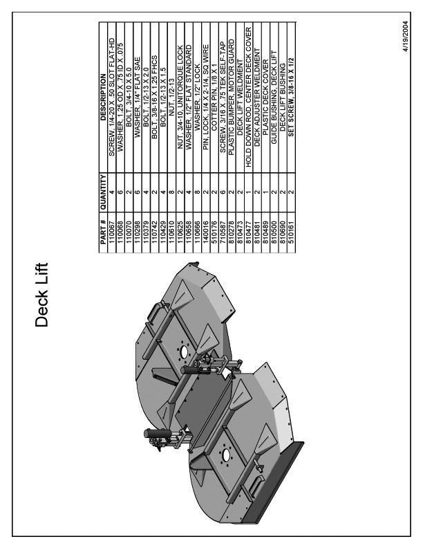
15 Deck Lift Adjustment Adjustments Set the outside deck height using the pin and bushing and the hand crank. Set the pin and bushing to the correct height and then turn down the hand crank so that it will carry some of the load. With motor running use the deck lift switch to obtain the desired center height. IMPORTANT WHEN DONE CHANGING DECK HEIGHT ALWAYS REPLACE HAND CRANK PIN AND ALL BUSHING PINS. Seat Adjustment When the deck is at the desired center height, set the pin and bushing in the closest hole and let the deck down so that it rests on the stops The lever with the yellow handle controls the chair s horizontal movement. 2. The round knob adjusts the ride quality. Turn the knob clock-wise for a firmer ride, and counter-clockwise for a softer ride. ATM 72 LC 13


16 Adjust the screw to change the angle of the arm rests. Tow Valve Location The Tow Valve is located behind the right front cowling. The Tow Valve is accessible for adjustment through a small hole located in the cowling for this purpose. Adjust safety tether to allow proper seat travel and maintaining adequate safety. Tow Valve IMPORTANT THE TOW VALVE MUST BE OPENED BE- FORE THE UNIT IS TOWED TO AVOID DAM- AGE TO THE HYDRAULIC PUMPS. To Open Tow Valve 1. Loosen the 9/16 locking nut. 2. Turn the 1/4 hex counter-clockwise a minimum of 2 full turns to ensure complete hydraulic system bypass. IMPORTANT TOWING OR PUSHING MOWER AT MORE THAN ONE MPH, WITH TOW VALVE LOSED, FOR MORE THAN 50 YARDS MAY CAUSE SERIOUS DAMAGE TO THE HY- DRAULIC PUMPS AND MOTORS. 14 ATM 72 LC
.")


17 NOTE: Always close the TOW VALVE before normal operation! If tow valve is left open the mower will operate but have little propulsion power. Level Adjustment The Manual Override Switch is located at the roll bar on the right hand side of the operator. Note: The Manual Override Switch is the rear switch (see picture). The box at the rear of the mower encloses the mercury switches that keep the machine level when the automatic leveling switch is on. To Adjust Mercury Switches Mower should be on level ground with the parking brake set, auto-level switch on, and engine at idle. Remove the two plastic covers from the mercury switch box. 1. Use manual over-ride switch to lean the mower to the right; release the switch and let the mower level itself. If the mower does not reach a vertical position, and is still leaning some to the right, turn the RIGHT adjusting screw counter-clockwise and repeat No. 1 procedure. Continue this adjustment until mower returns to vertical position. If mower passes vertical position, leaning some to the left, turn the RIGHT adjusting screw clockwise slightly and repeat No. 1 procedure. Continue this adjustment until mower returns to vertical position. 2. Use manual over-ride switch to lean the mower to the left; release the switch and let the mower level itself. If mower does not reach vertical position, and is still leaning some to the left, turn the LEFT adjusting screw counter-clockwise slightly and repeat No. 2 procedure. Continue this adjustment until mower returns to vertical position. If mower passes vertical position, leaning some to the right, turn the LEFT adjusting screw clockwise slightly and repeat No. 2 procedure. Continue this adjustment until mower returns to vertical position. ATM 72 LC 15


18 Neutral Adjustment If the machine creeps forward or backward when pedal is in neutral position, the neutral adjustment must be made. To Adjust 1. Remove the right side cowling. (The neutral adjustment is located behind the cowling and above the propulsion pump) 2. Position the screw on top of the neutral adjustment to the place where the mower does not creep forward or backward while in neutral. 16 ATM 72 LC
19 Service Parts/Points Filters Engine Air Filter... Deweze # Engine Oil Filter... Deweze # Engine Fuel Filter... Deweze # Engine Fuel/Water... Deweze # Hydraulic Return Filter... Deweze # Propulsion Pump Filter... Deweze # Hydraulic Tank Vent Filter... Deweze # Belts Fan/Alt. Belt... Deweze # Blades Blade Set (Right) Swinging... Deweze # Blade Set (Left) Swinging... Deweze # Bolt Kit (Swinging) 1 Deck... Deweze # Blade Set (Right) Shear bolt... Deweze # Blade Set (Left) Shear bolt... Deweze # Bolt Kit (Shear Bolt) 1 Deck... Deweze # Tires and Wheels Stabilizer Wheel Assy... Deweze # Caster Wheel Assy... Deweze # Drive Tire... Deweze # Drive Wheel (Rim)... Deweze # Drive Tire and Wheel Assy... Deweze # ATM 72 LC 17


20 Hydraulic Breather Change breather whenever hydraulic filter is serviced. Breather part number: Yanmar Engine - Right Side Fuel Filter Engine Oil Dipstick Hydraulic Filter Change hydraulic filter whenever filter indicator needle runs in the red area. NOTE: Check gauge when oil is at operating temperature. Fuel/Water Separator Engine Oil Fill Engine Oil Filter Radiator Fluid Overflow Propulsion Pump For access to the propulsion pump filter, the left hand cowling must be removed. Hydraulic Filter (822002) Breather Cap Propulsion Pump Filter Filter Indicator R 18 R ATM 72 LC
21 Service Schedule Disclaimer-On engine applications YANMAR Diesel Engine Co. recommends the following: Daily Check Engine oil level... Use HD 15-40, HD if below 40 F (19 C) Check Hydraulic oil level... Use HD or HD motor oil (HD SUPPLIED FROM FACTORY) Check fuel level... Use Clean #2 Diesel Visually inspect... Fan Belt, bolts, fittings, and hoses (for signs of leaks or looseness) Check Coolant Level... Between Low and Full, 50% Ethylene glycol Grease... refer to page Hour Service- These and all previous items Air Filter... Clean or replace Yanmar Check Tire Pressure PSI (6.9KPa-11Kpa) Drive tires Change Engine Oil liters dipstick upper limit/3.6 liters dipstick lower limit Change Engine Oil Filter... Yanmar / Deweze Hour Service-These and all previous items Change Engine Oil liters dipstick upper limit/3.6 liters dipstick lower limit Change Engine Oil Filter... Yanmar / Deweze Check Serviceability of Battery 200 Hour Service-These and all previous items Clean Fuel Filter according to Yanmar manual Drain Fuel / Water Separator Adjust Fan Belt Tension to Yanmar Manual 250 Hour Service Change Propulsion Pump Filter... Deweze Hour Service-These and all Previous items Replace the Fuel Filter... Yanmar / Deweze *Check Fuel Injection Condition* to Yanmar manual *Check Fuel Injection Timing* to Yanmar manual *Adjust the intake and Exhaust valve clearances* to Yanmar manual 1000 Hour Service or Annual Service-These and all previous items Change Hydraulic Oil... 8 gallon/ (30.28 liters) Change Engine Coolant gallon/ (5.7 liters) Repack stabilizer wheels... Use a high quality bearing grease *Check the Fuel Injection Pump* to Yanmar manual Parts with asterisk mark * should be serviced by an authorized YANMAR Dealer, unless the owner has proficient mechanical ability and the proper tools ATM 72 LC 19
22 NOTES ATM 72 LC
23 Harper Industries, Inc. 151 E. Highway 160 Harper, KS Website: ATM 72 LC Telephone: Toll-Free: Fax:
24 R R 2012 Harper Industries, Inc. All rights reserved. Printed in U.S.A. R 4/12 ATM 72 LC
25 R R Parts R 7/13 S/N 04A41 and above
26
27 Table of Contents Parts Section Frame & Assemblies Rear Assembly... Rear Wheel & Brake Assembly... Foot Pedal... Front Steering Assembly... Fuel Tank Assembly... Deck Lift... Stabilizer Assembly... Deck Assembly... Hood & Screens... Cowling & Dash Turn Signal Rear Harness... Electrical Schematic... Engine & Cooling Throttle... Engine Assembly... Engine Mounts & Exhaust... Radiator Assembly Hydraulic Systems Hydraulic Schematic... Propulsion Pump System Schematic... Leveling System Schematic... Deck Lift System Schematic... Deck Drive System Schematic... Steering System Schematic... Hydraulic Valve Service Parts... Deck Valve Lift Valve Leveling Valve Hydraulic Cylinder Parts... Front Deck Lift Cylinder Rear Deck Lift Cylinder Leveling Cylinder Steering Cylinder Deck Drive System... Deck Lift Hydraulic Assembly... Propulsion Hydraulics Assembly... Propulsion Pump Assembly... Steering System... Leveling Hydraulic Assembly... Reservoir & Filter Assembly... Electrical Systems Electrical... Head Lights Battery Cables Battery Battery Hold Down Flasher Flasher Lights Relays Relay & Fuse Block Mount Mercury Switch Enclosure Mercury Switch Assembly... Switches & Gauges... Electrical Harness TNV... Front Harness... Rear Harness... Panel Harness... Relay Harness... Turn Signal Option... Flasher Harness... Dash Harness... Power Harness
28
29 Section 3 Frame & Assemblies
30 Rear Assembly /9/
31 Rear Assembly PART # QUANTITY DESCRIPTION NUT, 7/16-20 BOLT, 1/2-13 X 1.0 NUT, LOCK BOLT, 3/8-16 X 1, WIZ FLANGE BOLT, 5/16-18 X 4.0 BOLT, 5/16-18 X 1, WIZ FLANGE BOLT, 7/16-20 X 1.5 NUT, 5/16-18 LOCK (NYLON) NUT, 5/16-18 WIZ FLANGE NUT, 1/2-13 NUT, 3/8-16 WIZ FLANGE WASHER, 1/2" LOCK WASHER, 7/16" LOCK HOLDER, MANUAL SCREW, X 0.5, RHMS SCREW, 1/4 X 1 TEK SELF-TAP SCREW, 3/16 X.75 TEK SELF-TAP SEAT, COMPLETE SHOCK ABSORBER SUSPENSION COVER ICP BRACKET ASSY TETHER KIT " TRACK SET LPS HD MECH W/O BOOT SET, FRONT ADJ ARMS TRIMLINE BACK COVER TRIMLINE CUSHION COVER SEAT BELT WEIGHT ADJ KNOB SWITCH, EVC ULB TRIMLINE-FXD SEAT SAFETY SWITCH ROPS, ATM 72 LIGHT BRACKET LEVELING SWITCH BRACKET LEVELING SWITCH GUARD, FRONT LEVELING SWITCH GUARD, BACK SAFETY SWITCH BRACKET SEAT SWITCH TIME DELAY MOUNT FRAME WELDMENT, 72LC REAR BUMPER WELDMENT 2/9/2006 ii 1.1
32 PART # QTY DESCRIPTION PART # QTY DESCRIPTION BOLT, M12x1.75 x 30 SHCS SAFETY SWITCH STOP BOLT, 1/2-13 X 2.0 SHCS SWITCH, BRAKE NO-NC NUT, 5/16-18, CAGE TINNERMAN BOOT FOR BOLT, WHEEL, 7/ BRAKE DRUM BOLT, 3/8-16 X CABLE, HAND BRAKE BOLT, 5/16-18 X 0.75, WIZ FLANGE BRAKE ASSY, REAR NUT, 1-20, SLOTTED BRAKE SHOE NUT, 3/8-16 WIZ FLANGE CYLINDER, WHEEL FOOT BRAKE WASHER, 5/16" FLAT STANDARD BRAKE SHOE, W/HAND BRAKE ATTACH SCREW, X 0.5, RHMS SPRING, BRAKE RETURN, KNOTT WIRE CLIP SPRING, HOLDING, KNOTT KEY, 5/16 X 1 WOODRUFF SPRING, HOLD DOWN, KNOTT HAND BRAKE CLEVIS, YOKE CLEVIS PIN, 5/16" DIA. x 1 3/8" LENGTH CLIP, E-Ring E COTTER PIN, 3/32 X WHEEL ASSEMBLY WHEEL TIRE Rear Wheel Brake Assembly /16/
33 R
34 1.3
35 Foot Pedal & Throttle AFTER S/N 07A PART # QUANTITY DESCRIPTION ROLL PIN, 3/8 X CLIP, E-Ring E BOLT, 3/8-16 X 1, WIZ FLANGE BOLT, M6x1 x 16 Gr NUT, 3/8-16 LOCK NYLON INSERT NUT, 1/ NUT, LOCK NYLON INSERT NUT, 1/4-28, UNITORQUE LOCK WASHER, 1/4" FLAT STANDARD WASHER, 3/8" FLAT STANDARD WASHER, 6 mm LOCK GREASE ZERK, 1/ deg SCREW, X 1, RHMS BEARING, ROD END 1/4-28 W/STUD THROTTLE CABLE BUSHING, IGUS, FOOT PEDAL FOOT PEDAL PAD, RUBBER W/NUBBINS FOOT PEDAL ASSY THROTTLE CABLE BRACKET TRACTION LEVER WELDMENT FOOT PEDAL BRACKET, WELDMENT FOOT PEDAL LINKAGE, ALLTHREAD /13/2006
36 1.4
37 TO WATER SEPERATOR / PUMP RETURN Fuel Tank Assembly D ESCR IPT ION BOLT, 3/8-16 X 0.75, WIZ FLANGE PART # QUANTITY FUEL CAP NUT ADAPTER, 5HB-6FBX CLAMP, HOSE #6.375 MINI FUEL TANK VALVE, FUEL SHUT OFF 6MB-4MP FUEL HOSE GAUGE, FUEL GASKET /15/
38 1.6
39 ii 1.6
40 R 1.7 8/4/ Stabilizer Assembly
41 Stabilizer Assembly PART # QUANTITY DESCRIPTION PART # QUANTITY DESCRIPTION BUSHING, 1-1/2 X 1-1/4 X 1-1/2 MSI LEVELING CYLINDER PIN WASHER, X.563 X.125, FLAT SPECIAL COTTER PIN, 1/8 X WASHER, 1.25 OD X.75 ID X BRASS BUSHING, EQUALIZER ARM BOLT, 1/2-13 X 1, WIZ FLANGE BUSHING, 1.25 X 1.0 X.75 SPLIT STEEL BOLT, 1/2-13 X FILLED STABILIZER TIRE ASSEMBLY NUT, CASTLE 3/ BRASS BUSHING, OUTER DECK ARM WASHER, 1/2" FLAT STANDARD BUSHING, 1.0 X.75 X 1.25 SPLIT STEEL WASHER, 1/2" LOCK BUSHING, 1.0 X.75 X 1.00 SPLIT STEEL WASHER, 3/4 FLAT SAE BUSHING, 1.0 X.75 X.75 SPLIT STEEL PIN, LOCK, 1/4 X 2-1/4, SQ WIRE BUSHING, IGUS MFI COTTER PIN, 3/16 X PIN, LEVELING CYLINDER BASE GREASE ZERK, 1/ deg EQUALIZER ARM ASSY GREASE ZERK, 1/4-28 ST PIN, STABILIZER PIVOT COTTER PIN, 3/16 X PIN ASSY, EQUILIZER ARM MOUNT HUB ASSEMBLY BUSHING, SPLIT RING TENSION NUT, 1/2-20 LUG SLIDE ASSY, OUTER DECK ADJ BEARING CUP, 1.98 X GUIDE BUSHING, DECK LIFT BEARING CONE, TAPER 1.0 X VERTICAL SHAFT SEAL, CR STABILIZER ARM WELDMENT, RIGHT DUST CAP STABILIZER ARM WELDMENT, LEFT HUB OUTER DECK ARM WELDMENT, W/O STEP INCLUDES PART# , , OUTER DECK ARM WELDMENT, W/ TREAD GRIP STEP INCLUDES PART# , , /4/2004 ii 1.7
42 Deck Assembly /10/
43 Deck Assembly PART # QUANTITY PLUG, 7/16", NYLON, SNAP LOCK BOLT, 1/2-13 X DESCRIPTION BOLT, 1/2-13 X 1, WIZ FLANGE BOLT, 3/4-10 X 6.75 BOLT, 3/8-16 X 1, WIZ FLANGE BOLT, 1/2-13 X 1.25 NUT, 1/2-13, UNITORQUE LOCK NUT, 3/4-10, UNITORQUE LOCK NUT, 3/8-16 WIZ FLANGE WASHER, 1/2 FLAT SPECIAL 1.5 OD WASHER, 7/16" FLAT STANDARD WASHER, 1/2 EXT. TOOTH LOCK ROLL PIN, 1/4 X 0.75 ROLL PIN, 1/4 X 1.5 BLADE KIT, LEFT BLADE KIT, RIGHT BOLT KIT BOLT, 1/2-20 X 1.5, GR NUT, 1/2-20, UNITORQUE LOCK WASHER, 1/2 FLAT SPECIAL 1.5 OD BUSHING, BLADE MOUNT GREASE ZERK, 1/4-28 ST KEY, 1/4 X 1/4 X 1.0 in PIN, WIRE LOCK CASTER WHEEL ASSY BUSHING, MFI COVER, VINYL, 1/2 RND X 6.0 BUSHING, MSI HUB, BLADE MOUNT WASHER, BLADE MOUNT BLADE MOUNT BLADE SADDLE CRANK ASSY, RIGHT CRANK ASSY, LEFT DECK WELDMENT, RIGHT DECK WELDMENT, LEFT DUST CAP CASTER YOKE WELD ASSY, W/SHORT SHAFT ADJUSTMENT SCREW WELD ASSY, W/C'BORE CASTER ARM WELD ASSY, RIGHT CASTER ARM WELD ASSY, LEFT 9/10/2004 ii 1.8
44 1.9
45 Cowling & Dash PART # QUANTITY DESCRIPTION /4-20 U-TYPE TAPPED HOLE RIVET, POP, 5/32 X BOLT, 1/4-20 X 1-1/ BOLT, 1/4-20 X NUT, 1/4-20 LOCK (NYLON INSERT) WASHER, 1/4" FLAT STANDARD WASHER, 1/4 NYLON SCREW, X 1 TRUSS HEAD NUT, THREADED INSERT SCREW, 1/4-20 X 1.0, PAN PHILIP LATCH COWLING BRACKET, SIDE COWLING BRACKET, TOP COWLING BRACKET HOOD LATCH MOUNT, LEFT HOOD LATCH MOUNT, RIGHT INSTRUMENT PANEL COWLING DASH COW LING, RIGHT COWLING, LEFT /9/
46
47 Section 4 Hydraulic Systems
48 2.1
49 2.2
50 2.3
51 2.4
52 2.5
53 2.6
54 2 3 Hydraulic V alve S ervice P arts Deck Valve P /N S E R V IC E P AR T S DE S C R IP T ION QUANT ITY P AR T # C OIL C OUNTE R BALANCE P R E S S UR E R E LIE F V ALV E S POOL Lift V alve P /N S E R V IC E P AR T S DE S C R IP T ION Q UANT IT Y P AR T # C OIL S P O OL Leveling V alve P /N S E R V IC E P AR T S DE S C R IP T ION Q UANT ITY P AR T # C OIL S POOL /19/
55 Hydraulic C ylinder S ervice P arts R E T AINING R ING U-C UP B AC K -UP O-R ING T E F LON R ING O-R ING WIP E R HEAD S E T -S C R E W (820129) C Y L INDE R / P A R T NUM B E R S E A L K IT R E T A INING R ING F R O NT DE C K L IF T R E A R DE C K L IF T L E V E L ING * S TE E R ING ** HEAD * 72LC AFTE R S /N 04A21 ** 72LC AFTE R S /N 04A41 WE AR R ING 7/19/
56 Deck Drive System LEFT RIGHT P MP MR T PART # QUANTITY DESCRIPTION BOLT, 5/16-18 X NUT, 5/ ADAPTER, 10MJ-12MB ADAPTER, BULKHEAD, 8MJ-8MJ ADAPTER, BULKHEAD, 4MJ-4MJ ADAPTER, 4MJ-4MB ADAPTER, 10MJ-10MB CLAMP, HOSE #12.75" OIL COOLER HOSE, CASE DRAIN DECK VALVE HOSE, "T" SIDE OF VALVE TO OIL COOLER HOSE, "MR" SIDE OF VALVE TO BACK RIGHT BULKHEAD HOSE, "MP" SIDE OF VALVE TO FRONT RIGHT BULKHEAD HOSE, "P" SIDE OF VALVE TO BACK LEFT BULKHEAD HOSE, RIGHT DECK MOTOR TO BACK RIGHT BULKHEAD HOSE, FRONT RIGHT BULKHEAD TO LEFT DECK MOTOR HOSE, LEFT DECK MOTOR TO RIGHT DECK MOTOR HOSE, OIL COOLER TO INTANK FILTER HOSE, CHARGE PUMP TO BACK LEFT BULKHEAD HOSE, RESERVOIR TO CHARGE PUMP SUCTION HOSE, CASE DRAIN BULKHEAD TO RESEVOIR MOTOR, DECK LEFT, ULTRA MOTOR, DECK RIGHT, ULTRA /14/
57 Deck Drive System SEE PROPULSION PUMP ASSEMBLY 7/14/2004 ii 2.9
58 2.10
59 R
60 2.11
61 ii 2.11
62 DESCRIPTION ADAPTER, 6MJ-8MB90 ADAPTER, 12MJ-10MB ADAPTER, 8MB-8MJ45 PART # QUANTITY DESCRIPTION PART # QUANTITY ROLL PIN, 3/16 X BOLT, 3/8-16 X 1.0 SHCS BOLT, 1/4-20 X BOLT, 1/2-13 X BOLT, M10x1.5 x 40, Gr NUT, 1/4-20 LOCK (NYLON INSERT) WASHER, 1/2" FLAT STANDARD WASHER, 1/2" LOCK WASHER, 1/4" LOCK WASHER, 3/8" LOCK ADAPTER, 10MJ-12MB SEAL KIT ADAPTER, 12MJ-16MB90 ADAPTER, 8MJ-8MB GREASE ZERK, 1/ deg BUSHING, IGUS, FOOT PEDAL BELL HOUSING NEUTRAL SAFETY SWITCH BRACKET SPACER,.406 X.26 X.50 FOOT PEDAL BRACKET, WELDMENT ACTUATOR ARM WELDMENT SAFETY SWITCH ACTUATOR WELDMENT O-RING, -236 PUMP, DECK DRIVE 1.28 PUMP, PROPULSION 1.35/.61 CHRG SWITCH ROLLER PLUNGER HARNESS, NEUTRAL SAFETY SWITCH PUMP DRIVE COUPLING Propulsion Pump Assembly /9/
63 DE S CR IPTION ADAPTE R, 6MJ-8MB90 ADAPTE R, 12MJ-10MB ADAPTE R, 8MB-8MJ45 ADAPTE R, 12MJ-16MB90 ADAPTE R, 8MJ -8MB GR E AS E ZE R K, 1/ deg BUS HING, IGUS, FOOT PE DAL BE LL HOUS ING NE UTR AL S AFE TY S WITCH BR ACKE T S PACE R,.406 X.26 X.50 FOOT PEDAL BRACKET, WELDMENT ACTUATOR AR M WE LDME NT SAFETY SWITCH ACTUATOR WELDMENT O-R ING, -236 PUMP, DE CK DR IVE 1.28 PUMP, PR OPULS ION 1.35/.61 CHR G PART # QUANTITY DE S CR IPTION PART # QUANTITY BOLT, 1/4-20 X 1.25 S HCS R OLL PIN, 3/16 X BOLT, 3/8-16 X 1.0 S HCS BOLT, 1/4-20 X BOLT, 1/2-13 X BOLT, M10x1.5 x 40, Gr NUT, 1/4-20 LOCK (NYLON INS E R T) W AS HE R, 1/2" FLAT S TANDAR D W AS HE R, 1/2" L O C K W AS HE R, 1/4" LOCK W AS HE R, 3/8" L O C K ADAPTE R, 10MJ-12MB S E AL KIT SWITCH ROLLER PLUNGER HARNESS, NEUTRAL SAFETY SWITCH PUMP DR IVE COUPLING P ropulsion P ump Assembly F OR S /N's 06A08 TO 06A /10/2006 ii 2.12
64 PART # QUANTITY DESCRIPTION PART # QUANTITY BOLT, 1/4-20 X 1.25 SHCS ROLL PIN, 3/16 X BOLT, 3/8-16 X 1.0 SHCS BOLT, 1/4-20 X BOLT, 1/2-13 X NUT, 1/4-20 LOCK (NYLON INSERT) WASHER, 1/2" FLAT STANDARD WASHER, 1/2" LOCK WASHER, 1/4" LOCK WASHER, 3/8" LOCK ADAPTER, 10MJ-12MB DESCRIPTION ADAPTER, 6MJ-8MB90 ADAPTER, 12MJ-10MB ADAPTER, 8MB-8MJ45 ADAPTER, 12MJ-16MB90 ADAPTER, 8MJ-8MB BELL HOUSING NEUTRAL SAFETY SWITCH BRACKET SPACER,.406 X.26 X.50 ACTUATOR ARM WELDMENT SAFETY SWITCH ACTUATOR WELDMENT O-RING, -236 PUMP, DECK DRIVE 1.28 PUMP, PROPULSION 1.35/ CHRG SEAL KIT SWITCH ROLLER PLUNGER HARNESS, NEUTRAL SAFETY SWITCH PUMP DRIVE COUPLING Propulsion Pump Assembly FOR S/N's AFTER 07A /13/2006 iii 2.12
65 R
66 PART # QUANTITY DE S CR IPTION PART # QUANTITY DE S CR IPTION BOLT, M10x1.5 x 20 Gr S TE E R ING PUMP MOUNT BOLT, 3/8-16 X 1, W IZ FLANGE HOSE, LT STEERING VALVE TO BULKHEAD BOLT, 1/4-20 X HOSE, RT STEERING VALVE TO BULKHEAD NUT, 5/ HOSE, ROD END TO LT BULKHEAD NUT, 3/8-16 W IZ FLANGE HOSE, BARREL END TO RT BULKHEAD W AS HE R, 7/16" LOCK HOSE, AUX OF STEERING TO "P" OF LEVELING ADAPTE R, 6MJ -6MJ -6MB PRESSURE SIDE OF PROP TO IN SIDE OF STEERING ADAPTE R, BULKHE AD, 4MJ-4MJ HOSE,STEERING OUT TO FILTER ADAPTE R, 6MJ-6MB HOSE, FILTER TO PUMP ADAPTE R, 4MJ-4MB FILTE R HE AD, S PIN ON, 6 FB POR TS 1 FILTER ELEMENT S T EE RIN G C Y LIND E R STEERING COLUMN STEERING PUMP STEERING WHEEL OIL FILTE R BR ACKE T S teering S ystem 7/12/
67 OUT LT AUX IN RT Steering System LT RT STEERING VIEW FROM BOTTOM TO PUMP TO "P" OF LEVELING O A L R I FROM PUMP STEERING WHEEL 7/12/2004 ii 2.13
68 F R OM S T E E R ING AUX T O DE C K LIF T # Leveling Hydraulics As s embly F OR S /N's AF T E R 04A01 S /N 04A01-05A65 # Dalton B earing Hydraulics S /N 06A01 and above # C ross Manufacturing S/N 06A46 and above # was added as left cylinder (prior to 06A46 both left and right cylinders were alike) S 2 S /22/
69 Leveling Hydraulics As sembly F OR S /N's AF T E R 04A01 S /N 04A01-05A65 # Dalton B earing Hydraulics S /N 06A01 and above # C ross Manufacturing S/N 06A46 and above # was added as left cylinder (prior to 06A46 both left and right cylinders were alike) P AR T # QT Y DE S C R IP T ION B OLT, 5/16-18 X NUT, 5/16-18 W IZ F LANG E ADAP T E R, 6MJ -6MJ -6MB ADAP T E R, 4MJ -4MP ADAP T E R, 6MJ -6F J X-6MJ ADAP T E R, 4MJ -8MB ADAP T E R, 4MJ -4MB ADAP T E R, 4F J X-4MP ADAP T E R, 6MJ -6MB C LAMP, HOS E # " HY DR O P NE UMAT IC AC C UMULAT OR VALVE, LE VE LING HOS E, C 1 OF LE VE LING T O B AR R E L OF R IG HT HOS E, C 2 OF LE VE LING T O B AR R E L E ND OF LE F T HOS E, C 2 OF LE VE LING T O R OD E ND R IG HT HOS E, C 2 OF LE VE LING T O LE F T AC C UMULAT OR HOS E, C 1 OF LE VE LING T O R OD E ND LE F T HOS E, C 1 OF LE VE LING T O R IG HT AC C UMULAT OR C Y LINDE R, 3.0" X 6.54" X 2.0", LE VE LING, RIGHT B ALL VALVE W /HANDLE LE F T B ALL VALVE W /HANDLE R IG HT C Y LINDE R, 3.0" X 6.54" X 2.0", LE VE LING, LEFT LE F T R IG HT C 1 C 2 T O DE C K LIF T #3 S 1 T P S 2 F R OM S T E E R ING AUX. 2/22/2006 ii 2.14
70 2.15
71 Section 5 Electrical System
72 PART # QUANTITY DESCRIPTION PART # QUANTITY DESCRIPTION NUT, 1/4-20 WIZ FLANGE FLASHER BOLT, 1/4-20 X 1-1/ GROUND CABLE BOLT, 1/4-20 X RELAY BOLT, 1/4-20 X 0.75, WIZ FLANGE HAZARD LIGHT NUT, 1/ BATTERY HOLD DOWN WELDMENT NUT, 5/ RELAY & FUSE BLOCK MOUNT WELDMENT A NUT, LOCK NYLON INSERT STARTER TERMINAL COVER WASHER, 1/4" LOCK POSITIVE BATTERY CABLE WASHER, 1/4" FLAT STANDARD STARTER GROUND INSULATOR CAP, (ALTERNATOR) BATTERY BATTERY BOOT, RED MERCURY SWITCH ENCLOSURE, DEUTSCH ASSY BATTERY BOOT, BLACK HEADLIGHT LEFT, DEUTSCH ASSY SCREW, X 1, RHMS HEADLIGHT RIGHT, DEUTSCH ASSY ELECTRICAL /2/
73 3.2
74 Switches & Gauges PART # QUANTITY DESCRIPTION HOUR METER OIL PRESSURE GAUGE INDICATOR LIGHT VOLT METER TEMPERATURE GAUGE IGNITION SWITCH KEY SWITCH, PADDLE, CARLING (280063) SWITCH, PADDLE, CARLING (29261) SWITCH MOUNT, END MOUNT, SWITCH (VMS) SWITCH, LEVELING (MANUAL OVERRIDE) SWITCH, LEVELING RIGHT-LEFT (Switch) /28/2004
75 HEAD LIGHT HARNESS # Electrical Harness TNV AFTER S/N 04A41 RELAY, FUSE PANEL HARNESS # INSTRUMENT PANEL HARNESS # FRONT HARNESS # REAR HARNESS # SEAT SWITCH TIME DELAY HARNESS # HEATING ELEMENT TIMER HARNESS # (OPTIONAL) 2/9/
76
77 3.5
78 3.6
79 3.7
80 3.8
81 DETAIL A Turn Signal Option A /23/
82 Turn Signal Option PART # QUANTITY DESCRIPTION NUT, 1/4-20 WIZ FLANGE BOLT, 1/4-20 X 0.5, WIZ FLANGE BOLT, 5/16-18 X 0.75, WIZ FLANGE NUT, 5/16-18 WIZ FLANGE DECAL, INSTR. PANEL (72LC SIGNAL OPT) INSTRUMENT PANEL TURN SIGNAL BRACKET CLAMP TURN SIGNAL BRACKET WELDMENT, LEFT TURN SIGNAL BRACKET WELDMENT, RIGHT FLASHER, 12V RELAY 3 TERMINAL SWITCH MOUNT, END SWITCH MOUNT, MIDDLE HORN SWITCH, HAZARD LIGHT MOUNT, SWITCH (VMS) HOLE PLUG (VHP) HARNESS, FLASHER, 72 LIGHT KIT SWITCH, HORN SWITCH, TURN SIGNAL (DIRECTION LIGHT) TAILLIGHT, COMBINATION FRONT & REAR NOT SHOWN DASH HARNESS POWER HARNESS TURN SIGNAL, REAR HARNESS ii 3.9
83 3.10
84 3.11
85 3.12
86 3.13
87
88 Section 6 Engine and Cooling
89 4.1
90 Engine Assembly Air Filter Bracket P/N: PART # QUANTITY DESCRIPTION BOLT, 5/16-18 X 1.25, WIZ FLANGE BOLT, M12x1.75 x 20 Gr BOLT, 5/16-18 X 1, WIZ FLANGE BOLT, M8x1.25 x 20 Gr BOLT, 1/4-20 X NUT, 5/16-18 WIZ FLANGE NUT, 1/4-20 LOCK (NYLON INSERT) WASHER, 1/2" LOCK WASHER, 5/16" LOCK BOLT, M6x1 x 40 Gr ADAPTER, BRAKE LINE ADAPTER, 5BH-4MP PLUG, 1/4 PIPE, HEX SOCKET ADAPTER, M22 (1.5)-4FB PLUG, 4MB, INT SH CLAMP, HOSE # " OIL PRESSURE SENDER AIR CLEANER BRACKET W/ SEPERATOR MOUNT FUEL FILTER BRACKET FUEL PUMP BRACKET FUEL HOSE FILTER, FUEL/WATER SEPERATOR FILTER, SPIN ON FUEL/WATER SEPERATOR COOLANT TEMP SENDER AIR INTAKE TUBE AIR FILTER ASSY, DONALDSON AIR FILTER ELEMENT FUEL PUMP, ELECTRIC TNV ELBOW, CLOSE RADIUS FAN, TNV ENGINE RETURN TO TANK FROM TANK /18/
ATM 72 LC PARTS MANUAL ATM 72LC. Serial # 04A41 & Above
 ATM 72 LC R PARTS R MANUAL 4-2016 Serial # 04A41 & Above Table of Contents Parts Section Frame & Assemblies Rear Assembly... Rear Wheel & Brake Assembly... Foot Pedal... Front Steering Assembly... Fuel
Parts ATM 72LC 7/13. S/N 04A41 and above
 R R Parts R 7/13 S/N 04A41 and above Table of Contents Parts Section Frame & Assemblies Rear Assembly... Rear Wheel & Brake Assembly... Foot Pedal... Front Steering Assembly... Fuel Tank Assembly... Deck
ATM 72 LC OPERATOR S MANUAL ATM 72 LC. Serial # 04A41 & Above
 R OPERATOR S R MANUAL 8-2015 Serial # 04A41 & Above Thank you for purchasing a Harper ATM 72. TO THE OWNER OR OPERATOR: Please take time to read this manual carefully before operating the ATM 72. Each
ATM 72 LC OPERATOR S MANUAL ATM 72 LC
 R OPERATOR S R MANUAL 8-2017 Thank you for purchasing a Harper ATM 72. TO THE OWNER OR OPERATOR: Please take time to read this manual carefully before operating the ATM 72. Each operator should be familiar
DEBRIS BLOWER 2700 OPERATOR S MANUAL. Debris Blower
 DEBRIS BLOWER 2700 OPERATOR S MANUAL 6-2015 Thank you for purchasing a Harper. As with all Harper products, the has been developed through tough design and testing procedures to produce a top quality
DEBRIS BLOWER 3600 OPERATOR S MANUAL. Debris Blower
 DEBRIS BLOWER 3600 OPERATOR S MANUAL 9-208 Thank you for purchasing a Harper. As with all Harper products, the has been developed through tough design and testing procedures to produce a top quality machine.
Operator's Manual. VC-60 & VC-60 Plus Harper Industries, Inc. 7/03 Part No
 Operator's Manual VC-60 & VC-60 Plus 2003 Harper Industries, Inc. 7/03 Part No. 970066 Thank you for purchasing a Harper/Goossen Verti-Cutter. As with all Harper/Goossen products, the Harper/Goossen Verti-Cutter
ATM 162 HD OPERATOR S MANUAL ATM 162
 HD R OPERATOR S MANUAL 3-2015 1 2 Thank you for purchasing a Harper. TO THE OWNER OR OPERATOR: Please take time to read this manual carefully before operating the. Each operator should be familiar with
Parts Manual WH3615/ WH4817/ WH5217/ English
 Parts Manual WH6/66400 WH48/664002 WH2/66400 Please read the operator s manual carefully and make sure you understand the instructions before using the machine. English 2008 HTC. All rights reserved. Beatrice,
REAR ENGINE RIDER 42 MOWER SERIES 22
 Parts Manual for REAR ENGINE RIDER MOWER SERIES MODELS 1BVE CONTENTS DESCRIPTION PAGE(S) DESCRIPTION PAGE(S) WHEELS- TIRES... - FRONT END, STEERING.... - MAIN CASE... - DIFFERENTIAL, R. H. FENDER... 8-9
EUROPEAN REAR ENGINE RIDER SERIES 20
 Parts Manual for EUROPEAN REAR ENGINE RIDER SERIES 20 MODEL E281320BE E331520KVE McDonough, GA, 30253 U.S.A. Briggs & Startton Yard Power Products Group Copyright 2006 Briggs & Startton Corporation Milwaukee,
Operating and Assembly Manual
 Model 455-IC/PRO/H Operating and Assembly Manual Midwest Equipment Manufacturing, Inc. 5225 Serum Plant Road Thorntown, IN 46071 03-08-12 SAFETY RULES Remember, any power equipment can cause injury if
Operating and Assembly Manual
 Model 455-IC/PRO/H Operating and Assembly Manual Palmor Products Inc. 5225 Serum Plant Road Thorntown, IN 46071 03-08-12 SAFETY RULES Remember, any power equipment can cause injury if operated improperly
Parts Manual MZ5225 /
 Gasoline containing up to 10% ethanol (E10) is acceptable for use in this machine. The use of any gasoline exceeding 10% ethanol (E10) will void the product warranty. Parts Manual MZ5225 / 966690502 Please
G190 LT-145 (1992) Page 1 of 27 42" Mower Deck
 Page 1 of 27 42 Mower Deck") 132-736G190 LT-145 (1992) Page 1 of 27 42" Mower Deck 132-736G190 LT-145 (1992) Page 2 of 27 42" Mower Deck 3 17600A 1 S 42" Deck Ass'y. Code: N notates a new part (not previously existing). 813-06119
132-736G190 LT-145 (1992) Page 1 of 27 42" Mower Deck 132-736G190 LT-145 (1992) Page 2 of 27 42" Mower Deck 3 17600A 1 S 42" Deck Ass'y. Code: N notates a new part (not previously existing). 813-06119
OPERATOR S MANUAL FABRIC 3-BAG GRASS CATCHER PART NO PRINTED 8/2012 PRINTED IN USA
 OPERATOR S MANUAL FABRIC -BAG GRASS CATCHER Models: GC-STC-V This manual contains the operating instructions and safety information for your Scag mower accessory. Reading this manual can provide you with
YARD CRUISER HYDRO DRIVE HZ SERIES 3 & YZ SERIES 4
 Parts Manual for HYDRO DRIVE HZ SERIES 3 & YZ SERIES 4 MODEL HZS15423KVE HZS18483BVE YZ16424BVE YZ20484BVE McDonough, GA, 30253 U.S.A. COPYRIGHT 2005 SNAPPER PRODUCTS, INC. ALL RIGHTS RESERVED. Revision
Retriever 5800G/P/D. revised 2/01 Form Number
 Retriever 5800G/P/D PARTS LIST Advance MODELS 56482005, 56482010, 56482015 This parts list is for machines after serial number 221134 All models covered in this manual are OBSOLETE revised 2/01 Form Number
Parts Manual DX272 / Please read the operator s manual carefully and make sure you understand the instructions before using the machine.
 Parts Manual DX22 / 966651501 Please read the operator s manual carefully and make sure you understand the instructions before using the machine. Gasoline containing up to 10% ethanol (E10) is acceptable
Retriever PARTS LIST Advance MODEL 5200G(OBSOLETE)
") Retriever PARTS LIST Advance MODEL 5200G(OBSOLETE) 5/85 revised 2/01 FORM NO. 56042131 TABLE OF CONTENTS DESCRIPTION PAGE OUTER BODY...1-2 HYDRAULIC PUMP, ENGINE & FUEL TANK...3-4 HYDRAULIC OIL FILTER,
Retriever PARTS LIST Advance MODEL 5200G(OBSOLETE) 5/85 revised 2/01 FORM NO. 56042131 TABLE OF CONTENTS DESCRIPTION PAGE OUTER BODY...1-2 HYDRAULIC PUMP, ENGINE & FUEL TANK...3-4 HYDRAULIC OIL FILTER,
CHASSIS / FRAME REAR OF MOWER
 CHASSIS / FRAME 23 23 3 2 2 22 2 2 2 2 REAR OF MOWER 20 2 2 2 2 3 CHASSIS / FRAME... 3... 3... PAD-ABRASIVE 2... 3...... FRAME W/DECALS 3... 3 3...... FOOT PLATE W/DECALS...3... 2... KNOB W/STUD... 3 202......
Pavement Services, Inc.
 MG68 Parts Manual Pavement Services, Inc. Page 30 29 30 29 25 25 24 30 4 26 29 4 25 26 4 Page 2 The Decal Kit for the Model MG68 Maintainer is Item Part # Description 056859 DECAL, ANTI-FREEZE (BLACK)
72K850ZP PARTS MANUAL
 7 2 K 8 5 0 Z P PARTS MANUAL 72 MID-CUT GAS ENGINE OPTION SECTION 72 MID-CUT DECK ASSEMBLY 72" Mid-Cut Deck Assembly # PART NO. QTY DESCRIPTION 1 582096 1 72" MC DECK WELDMENT 2 582098 1 72" DECK CHANNEL
Parts Manual SERIES CVT Lawn Tractor. Model LT1040 CUB CADET LLC, P.O. BOX CLEVELAND, OHIO PRINTED IN U.S.A.
 Parts Manual CVT Lawn Tractor SERIES 000 Model LT00 PRINTED IN U.S.A. CUB CADET LLC, P.O. BOX CLEVELAND, OHIO -00 FORM -00C.fm (//00) SERIES 000 CVT LAWN TRACTORS TABLE OF CONTENTS DESCRIPTION PAGE Axle,
Operating and Assembly Manual
 Model 470-/H/PRO/IC Operating and Assembly Manual Midwest Equipment Manufacturing, Inc. 5225 Serum Plant Road Thorntown, IN 46071 11-11-11 SAFETY RULES Remember, any power equipment can cause injury if
72B27LD PARTS MANUAL
 7 2 B 2 7 L D PARTS MANUAL 6 MID-CUT SECTION 6 MID-CUT DECK ASSEMBLY 25 24 23 26 22 00 20 9B SEE NOTE A 9A 75 34 6 2 87 98 05 03 2 90 2 68 53 93 02 69 5 49 5 7 8 0 0 9 36 88 8 58 97 3 46 59 3 72 92 76
Operator s Manual SB /2014. Straw Blower
 R R Operator s Manual SB 5400 9/2014 Thank you for purchasing a Harper. As with all Harper products, the has been developed through tough design and testing procedures to produce a top quality machine.
PRO HYDRO WALK BEHIND MOWERS MID-SIZE SERIES 3
 Parts Manual for MID-SIZE SERIES 3 POWER UNIT MODELS SPLH153KW SPLH173KW MOWER MODELS SPA361 SPA481 SPA521 SPA611 McDonough, GA, 30253 U.S.A. COPYRIGHT 2005 SNAPPER PRODUCTS, INC. ALL RIGHTS RESERVED.
Model 452-DIC/DH. Operating and Assembly Manual
 . Model 452-DIC/DH Operating and Assembly Manual Palmor Products Inc. 5225 Serum Plant Road Thorntown, IN 46071 02-14-12 SAFETY RULES Remember, any power equipment can cause injury if operated improperly
Parts Manual Rev. A RZT48 /
 115 91 36-2 Rev. A Parts Manual RZT48 / 96 62001-00 Please read the operator manual carefully and make sure you understand the instructions before using the machine. Gasoline containing a maximum of 10%
PARTS CATALOG ODYSSEY INCLUDES MOWER
 PARTS CATALOG 8-3350 ODYSSEY INCLUDES MOWER INDEX PAINT ENGINES GENERAL INFO PRODUCT IDENTIFICATION NUMBERS (P.I.N.) OR SERIAL NUMBERS (S/N) ENGINE MODEL, SERIAL AND SPECIFICATION NUMBERS TRACTOR MODEL
ILLUSTRATED PARTS LIST THIS MANUAL CONTAINS THE ILLUSTRATED PARTS LIST FOR MODELS:
 IPL MODEL SWZU 1 6 2 6 6 6 6 ILLUSTRATED PARTS LIST 0 2 6 8 THIS MANUAL CONTAINS THE ILLUSTRATED PARTS LIST FOR MODELS: SWZU6-1KA with a serial number of 260001 to 26 SWZU8-1KA with a serial number of
Parts Manual Rev. 5
 0-0- CL 0 - Rev. Parts Manual MZ / 0-00 Please read the operator manual carefully and make sure you understand the instructions before using the machine. Gasoline containing a maximum of % ethanol (E)
25 Horsepower Hydrostatic Zero-Turn Commercial Riding Mower
 MMZ 2, 260 2 Horsepower Hydrostatic Zero-Turn Commercial Riding Mower ILLUSTRATED PARTS LIST " Float Cutter Deck - Figure 1 3 1 27 32 17 6 1 11 31 36 3 19 7 23 1 33 38 18 37 22 3 20 2 10 2 12 21 30 39
DIAMOND CONCRETE SAW PARTS LIST MODEL CC8000 P R O D U C T S. (Revised )
") DIAMOND P R O D U C T S CONCRETE SAW PARTS LIST MODEL CC8000 (Revised 10-15-2002) Table of Contents Page Saw Controls Legend. 3 Drawing 1. Frame Group. 4-5 Drawing 2. Arm Assembly... 6-7 Drawing 3. Hydraulics
DIAMOND P R O D U C T S CONCRETE SAW PARTS LIST MODEL CC8000 (Revised 10-15-2002) Table of Contents Page Saw Controls Legend. 3 Drawing 1. Frame Group. 4-5 Drawing 2. Arm Assembly... 6-7 Drawing 3. Hydraulics
Champion Series Zero-Turn Riders & Mower Decks
 Parts Manual Champion Series Zero-Turn Riders & Mower Decks HP Tractors Mfg. No. Description Champion, HP Zero-Turn Rider Champion, HP Zero-Turn Rider (CE) 0HP Tractors Mfg. No. Description Champion, 0HP
Operating and Assembly Manual
 Model 380/385-IC/385-LH Operating and Assembly Manual Midwest Equipment Manufacturing, Inc. 5225 Serum Plant Road Thorntown, IN 46071 2-0916 SAFETY RULES Remember, any power equipment can cause injury
Parts Manual MZ52 /
 Gasoline containing up to 10% ethanol (E10) is acceptable for use in this machine. The use of any gasoline exceeding 10% ethanol (E10) will void the product warranty. Parts Manual MZ52 / 962401 Please
Parts Manual Rev. B RZT48 /
 115 91 36-2 Rev. B Parts Manual RZT48 / 96 62001-00 Please read the operator manual carefully and make sure you understand the instructions before using the machine. Gasoline containing a maximum of 10%
52 MID-CUT DECK ASSEMBLY
 5 2 K 2 5 A PARTS MANUAL 52 MID-CUT SECTION 52 MID-CUT DECK ASSEMBLY 19 79 36 30 18 82 107 104 7 27 40 85 35 41 28 43 39 111 30 114 99 42 95 80 88 39 6 31 68 84 83 110 34 15 6 14 11 109 30 18 96 31 51
Hydrostatic Zero-Turn Commercial Riding Mower
 Hydrostatic Zero-Turn Commercial Riding Mower Professional Turf Equipment 0" Fabricated Deck ILLUSTRATED PARTS LIST TABLE OF CONTENTS Frame Assembly.................................. 3 0" Fabricated Cutter
REAR ENGINE RIDER EUROPEAN SERIES 22
 Parts Manual for REAR ENGINE RIDER EUROPEAN SERIES 22 MODELS E2822BE E2822BE E1522KVE CONTENTS DESCRIPTION PAGE(S) DESCRIPTION PAGE(S) WHEELS, TIRES...2, DRIVE DISC ASSEMBLY... 22 FRONT END, STEERING...4,
Worldlawn Power Equipment, Inc. Industrial Park 2415 Ashland Ave. Beatrice, NE Toll Free Number:
 Parts Catalog R Commercial / Residential 33 Mower Worldlawn Power Equipment, Inc. Industrial Park 2415 Ashland Ave. Beatrice, NE 68310 Toll Free Number: 1-800-267-4255 Table of Contents Table of Contents
74901, Z Master G3 Riding Mower, with 48in TURBO FORCE Side Discharge Mower, 2011 (SN ) : BRAKE HANDLE ASSEMBLY NO.
 : BRAKE HANDLE ASSEMBLY NO.") 74901, Z Master G3 Riding Mower, with 48in TURBO FORCE Side Discharge Mower, 2011 (SN 311000001-311999999) : BRAKE HANDLE ASSEMBLY NO. 1 Page 1 of 52 74901, Z Master G3 Riding Mower, with 48in TURBO FORCE
74901, Z Master G3 Riding Mower, with 48in TURBO FORCE Side Discharge Mower, 2011 (SN 311000001-311999999) : BRAKE HANDLE ASSEMBLY NO. 1 Page 1 of 52 74901, Z Master G3 Riding Mower, with 48in TURBO FORCE
MZ 52LE. Parts Manual. Zero Turn Mower /
 Parts Manual MZ 52LE Zero Turn Mower / 9677406-00 Please read the operator manual carefully and make sure you understand the instructions before using the machine. When you need spare parts or support
Operating and Assembly Manual
 Model 1080 Operating and Assembly Manual Midwest Equipment Manufacturing, Inc. 5225 Serum Plant Road Thorntown, IN 46071 08-02-16 SAFETY RULES Remember, any power equipment can cause injury if operated
Boxer 532DX Parts Manual
 BIG POWER IN ALL PLACES Boxer 5DX Parts Manual SN and Higher Part No. 5- Phone: Sales - 00--00, Parts and Service - 00-55- www.boxerequipment.com Manufactured by: Morbark, Inc. 50 S. Winn Rd., P.O. Box
OPERATOR S MANUAL MODEL GC-STC-V
 MODEL GC-STC-V THIS MANUAL CONTAINS THE OPERATING INSTRUCTIONS AND SAFETY INFORMA- TION FOR YOUR SCAG ACCESSORY. READ- ING THIS MANUAL WILL PROVIDE YOU WITH MAINTENANCE AND ADJUSTMENT PROCEDURES TO KEEP
ILLUSTRATED PARTS LIST
 IPL MODEL STHM 71 72 1 7 7 ILLUSTRATED PARTS LIST 70 2 7 THIS MANUAL CONTAINS THE ILLUSTRATED PARTS LIST FOR MODELS: STHM - 2CV with a serial number of 00001-0 SM-1A with a serial number of 001- SM-72A
ELECTRIC CLUTCH HYDRO DRIVE RMO TRACTORS LT-200 SERIES
 Parts Manual for ELECTRIC CLUTCH HYDRO DRIVE RMO TRACTORS LT-200 SERIES MODEL ELT18538 (2690497) ELT2044 (2690498) LT18538 (2690440) LT18500 (2690518) LT2042 (2690441) LT2044 (2690442) LT22500 (2690443)
WYZ34FS600VCA FOR SERIAL NUMBERS U02011 AND ABOVE
 PARTS MANUAL WYZ34FS600V WYZ34FS600VCA FOR SERIAL NUMBERS 201610U02011 AND ABOVE 2 3 4 CONTENTS GENERAL INFORMATION... 6 SERVICE LOCATOR CHART... 7 DECK ASSEMBLY... 8 DECK LIFT ASSEMBLY... 10 FRAME ASSEMBLY...
Parts Manual ZMKW 5222 / ZMKW 6124 /
 Parts Manual ZMKW 222 / 6647801 ZMKW 6124 / 664701 Please read the operator s manual carefully and make sure you understand the instructions before using the machine. MODEL When you need spare parts or
Hydrostatic Zero-Turn Commercial Riding Mower
 Hydrostatic Zero-Turn Commercial Riding Mower Professional Turf Equipment 54" Fabricated Deck ILLUSTRATED PARTS LIST TABLE OF CONTENTS Frame Assembly.................................. 3 54" Fabricated
Parts Catalog. WYZ48/ 52/60 Zero Turn Mower. Worldlawn Power Equipment, Inc Ashland Avenue, Beatrice, NE Toll Free Number:
 Parts Catalog R WYZ48/ 52/60 Zero Turn Mower Worldlawn Power Equipment, Inc. 2415 Ashland Avenue, Beatrice, NE 68310 Toll Free Number: 1-800-267-4255 Content Content Mower Assembly.. 1 Mower Deck Assembly.
Parts Manual PZ Please read the operator manual carefully and make sure you understand the instructions before using the machine.
 Parts Manual PZ 60 967 045601-00 Please read the operator manual carefully and make sure you understand the instructions before using the machine. When you need spare parts or support in service questions,
Parts Manual PZ60 /
 Gasoline containing up to 10% ethanol (E10) is acceptable for use in this machine. The use of any gasoline exceeding 10% ethanol (E10) will void the product warranty. Parts Manual PZ60 / 966614301 Please
61 MID-CUT DECK ASSEMBLY
 6 1 K 2 8 A PARTS MANUAL A A 102 101 100 103 99 83 97 61 34 93 12 86 123 2 74 124 55 56 92 48 5 7 8 10 84 9 36 73 95 3 31 58 76 62 59 22 27 64 44 43 87 17 1 13 35 31 41 40 26 24 91 55 48 23 22 59 21 31
PARTS MANUAL EE60FX730V34CA EE52FX691V34CA
 PARTS MANUAL EE48FR691V32 EE48FR691V32CA EE60FX730V34 EE60FX730V34CA EE52FR691V32 EE52FR691V32CA EE52FX691V34 EE52FX691V34CA 2 WWW.ENCOREEQUIPMENT.COM 401 COMMERCE STREET BEATRICE, NE 68310 800-267-4255
Z253 Z Master with 62in SFS Side Discharge Mower
 Form No. REV A Z Z Master with 6in SFS Side Discharge Mower Model No. 00000 and Up Parts Catalog Ordering Replacement Parts To order replacement parts, please supply: the part number, the quantity, and
PIÈCES DÉTACHÉES ELT125D33 1KV. Tondeuse autoportée
 PIÈCES DÉTACHÉES Tondeuse autoportée ELT15D33 1KV Yvan Béal - 1, av. de l Agriculture - B.P. 16 Z.I. du Brézet - 63014 Clermont-Ferrand Cedex Tél : 04 73 91 93 51 - Télécopie : 04 73 90 3 11 www.yvanbeal.fr
Parts Manual Rev. A
 115 97 79-27 Rev. A Parts Manual Z 248F / 967 844801-00 Please read the operator manual carefully and make sure you understand the instructions before using the machine. Gasoline containing a maximum of
4200 & 6200 Owner s Manual & Parts Book
 00 & 00 Owner s Manual & Parts Book Purchase Date Serial Number Model Number Tractor Model PN: - Dealer Date --0 Description Page To The Owner & Maintenance Safety Precautions & Torque Specifications Skid
Parts Manual Rev. A
 115 96 28-27 Rev. A Parts Manual Z 242F / 967 271802-00 Please read the operator manual carefully and make sure you understand the instructions before using the machine. Gasoline containing a maximum of
Parts Manual P-ZT4822 / P-ZT5224 / P-ZT6126 / P-ZT6128BS / P-ZT26 BF / P-ZT4822 CARB /
 Gasoline containing up to 10% ethanol (E10) is acceptable for use in this machine. The use of any gasoline exceeding 10% ethanol (E10) will void the product warranty. Parts Manual P-ZT4822 / 966613301
57 ROUGH CUT OWNER S MANUAL. With Assembly Instructions For Model: MR55H KUNZ ENGINEERING, INC. / MENDOTA, IL / PH (815) /07
 /07") 57 ROUGH CUT OWNER S MANUAL With Assembly Instructions For Model: MR55H KUNZ ENGINEERING, INC. / MENDOTA, IL 61342 / PH (815) 539-6954 1/07 ASSEMBLY INSTRUCTIONS Read the complete assembly instructions
57 ROUGH CUT OWNER S MANUAL With Assembly Instructions For Model: MR55H KUNZ ENGINEERING, INC. / MENDOTA, IL 61342 / PH (815) 539-6954 1/07 ASSEMBLY INSTRUCTIONS Read the complete assembly instructions
Parts manual MANUAL NO REV. 04 (12/14/00)
") Parts manual Models: 968999159 / ZTH5221KAA 968999160 / ZTH5223KAA 968999161 / ZTH5223KOA 968999162 / ZTH5223KOLA 968999163 / ZTH5225KOA 968999165 / ZTH6125KOA 968999166 / ZTH6125KAA 968999171 / ZTH6126KOA
Parts manual Models: 968999159 / ZTH5221KAA 968999160 / ZTH5223KAA 968999161 / ZTH5223KOA 968999162 / ZTH5223KOLA 968999163 / ZTH5225KOA 968999165 / ZTH6125KOA 968999166 / ZTH6125KAA 968999171 / ZTH6126KOA
GRACO INC. P.O. BOX 1441 MINNEAPOLIS, MN
 REPAIR J Line Driver Model 233725 U.S. Patent Number 6,883,633 Important Safety Instructions Read all warnings and instructions in this manual. Save these instructions. 10 mph (16 kph) Maximum Operating
Parts Manual Rev. A RZT54 /
 115 93 37-27 Rev. A Parts Manual RZT54 / 967 672101-00 Please read the operator manual carefully and make sure you understand the instructions before using the machine. Gasoline containing a maximum of
Parts Manual DX254 / Please read the operator s manual carefully and make sure you understand the instructions before using the machine.
 Parts Manual DX254 / 966651203 Please read the operator s manual carefully and make sure you understand the instructions before using the machine. Gasoline containing up to 10% ethanol (E10) is acceptable
BEEFCAKE OPERATOR S & PARTS MANUAL Beefcake
 BEEFCAKE OPERATOR S & PARTS MANUAL -0 Thank you for purchasing a Harper. TO THE OWNER OR OPERATOR: As with all Harper products, the Harper has been developed through tough design and testing procedures
TECHNICAL DATA BROCHURE ZTR 308/3II
 Date 8/84 Page 1 of 6 TECHNICAL DATA BROCHURE ZTR 308/3II IMPORTANT - READ OPERATOR'S MANUAL BEFORE OPERATION OR MAKING ADJUSTMENTS. ' Seat Adjustment Loosen bolts on sliding brackets under each side of
HYDRAULIC ASSEMBLY (TL)
") HYDRAULIC ASSEMBLY (TL) REF. REF. 2 3 6 7 0 2 3 7 20 2 22 23 2 2 26 27 2 30 3 32 33 3 3 36 37 3 3 0 2 3 6 3 2 6 2 6 23 6 2 23 HYDRAULIC ASSEMBLY (TL)... 3 076...2... PULLEY 2... 3 077...2... KEY, MM SQ
HYDRAULIC ASSEMBLY (TL) REF. REF. 2 3 6 7 0 2 3 7 20 2 22 23 2 2 26 27 2 30 3 32 33 3 3 36 37 3 3 0 2 3 6 3 2 6 2 6 23 6 2 23 HYDRAULIC ASSEMBLY (TL)... 3 076...2... PULLEY 2... 3 077...2... KEY, MM SQ
Collection System. Please read the operator s manual carefully and make sure you understand the instructions before using the machine.
 Collection System 967004601 Please read the operator s manual carefully and make sure you understand the instructions before using the machine. 2012 All rights reserved. Swainsboro, GA. Printed in U.S.A.
Illustrated Parts Manual
 Illustrated Parts Manual Models 522D LoPro 524D LoPro S/N 0900 P/N - 948-403 Revised July 6, 2007 INTRODUCTION Table of Contents SECTION INTRODUCTION Table of Contents... - thru -4 Alphabetical Index...
Parts Manual P-ZT54 /
 Gasoline containing up to 10% ethanol (E10) is acceptable for use in this machine. The use of any gasoline exceeding 10% ethanol (E10) will void the product warranty. Parts Manual P-ZT54 / 9913402 Please
Wheel Horse. 36 Tiller. Model No & Up. Operator s Manual
 FORM NO. 8 9 Rev. A Wheel Horse 6 Tiller for Classic Garden Tractors Model No. 7970 690000 & Up Operator s Manual IMPORTANT: Read this manual carefully. It contains information about your safety and the
14A6816H190 GT-2150 (2003) Page 1 of 28 Carburetor
 Page 1 of 28 Carburetor") 14A6816H190 GT-2150 (2003) Page 1 of 28 Carburetor 14A6816H190 GT-2150 (2003) Page 2 of 28 Carburetor TC-640221 1 /P Carburetor (Incl 184 of Engine Parts Lists) 1 TC-640216 1 Throttle Shaft & Lever Assembly
14A6816H190 GT-2150 (2003) Page 1 of 28 Carburetor 14A6816H190 GT-2150 (2003) Page 2 of 28 Carburetor TC-640221 1 /P Carburetor (Incl 184 of Engine Parts Lists) 1 TC-640216 1 Throttle Shaft & Lever Assembly
365L (2001) Page 1 of 36 54" Deck Assembly
 Page 1 of 36 54 Deck Assembly") 365L (2001) Page 1 of 36 54" Deck Assembly 365L (2001) Page 2 of 36 54" Deck Assembly 1 720-0241 1 S Wing Nut Knob 2 703-2817 1 Belt Cover LH 3 703-2816 1 Belt Cover RH 4 747-3306 1 Idler Spring Mounting
365L (2001) Page 1 of 36 54" Deck Assembly 365L (2001) Page 2 of 36 54" Deck Assembly 1 720-0241 1 S Wing Nut Knob 2 703-2817 1 Belt Cover LH 3 703-2816 1 Belt Cover RH 4 747-3306 1 Idler Spring Mounting
Parts Manual for the Wright Z
 Parts Manual for the Wright Z Serial numbers 40581 & Higher Check www.wrightmfg.com for the latest revision Rev 9/2007 Shown with OPTIONAL Grass Collection System 2006 Wright Manufacturing Inc., All Rights
Parts Manual MZ5225ZT / MZ6128ZT / MZ6128ZT /
 Gasoline containing up to 10% ethanol (E10) is acceptable for use in this machine. The use of any gasoline exceeding 10% ethanol (E10) will void the product warranty. Parts Manual MZ5225ZT / 966690501
Parts Manual. Models: / Z4818BIA MANUAL NO REV. IR (09/18/04)
") Parts Manual Models: 968999250 / Z4818BIA MANUAL NO. 539109796 REV. IR (09/18/04) 2 INDEX MAIN FRAME ASSEMBLY... 4-5 BRAKE LINKAGE... 6 CONSOLE ASSEMBLY... 7 CASTER ASSEMBLY... 8 MOTION CONTROL ASSEMBLY...
Parts Manual Models: 968999250 / Z4818BIA MANUAL NO. 539109796 REV. IR (09/18/04) 2 INDEX MAIN FRAME ASSEMBLY... 4-5 BRAKE LINKAGE... 6 CONSOLE ASSEMBLY... 7 CASTER ASSEMBLY... 8 MOTION CONTROL ASSEMBLY...
Parts Manual for the Wright Z
 Parts Manual for the Wright Z Serial numbers 40581 & Higher Check www.wrightmfg.com for the latest revision Rev 6/2010 Shown with OPTIONAL Grass Collection System 2010 Wright Manufacturing Inc., All Rights
ELECTRIC CLUTCH HYDRO DRIVE RMO TRACTORS LT-200 SERIES
 Parts Manual for ELECTRIC CLUTCH HYDRO DRIVE RMO TRACTORS LT-200 SERIES MODEL ELT18538 (2690497) ELT18538 (2690796) ELT18540 (2690781) ELT2044 (2690498) LT18538 (2690440) LT18500 (2690518) LT2042 (2690441)
Model 858-RH. Operating and Assembly Manual. Palmor Products Inc Serum Plant Road Thorntown, IN 46071
 Model 5-RH Operating and Assembly Manual Palmor Products Inc. 55 Serum Plant Road Thorntown, IN 6071 3/31/015 SAFETY RULES Remember, any power equipment can cause injury if operated improperly or if the
CHASSIS / FRAME REF. BAT- TERY
 CHASSIS / FRAME REF. BAT- TERY 2 3 0 2 3 2 22 23 2 2 2 2 2 2 30 2 2 2 23 2 2 2 2 2 2 2 2 2 CHASSIS / FRAME... 3... 3... PAD-ABRASIVE 2... 3 0...... FRAME W/DECALS 3... 3 3...... FOOT PLATE W/DECALS...3
ILLUSTRATED PARTS LIST AND TECHNICAL MANUAL
 Chariot / Chariot LX TCU705 H ILLUSTRATED PARTS LIST AND TECHNICAL MANUAL c WARNING: The Engine Exhaust from this product contains chemicals known to the State of California to cause cancer, birth defects
Worldlawn Power Equipment, Inc. Industrial Park 2415 Ashland Ave. Beatrice, NE Toll Free Number:
 Parts Catalog R Commercial WY48 Mower Worldlawn Power Equipment, Inc. Industrial Park 2415 Ashland Ave. Beatrice, NE 68310 Toll Free Number: 1-800-267-4255 Table of Contents Table of Contents Mower Assembly..
IPL ILLUSTRATED PARTS MANUAL. Model SWZT Walk-Behind. with a serial number of K to K Part No Printed 12/13 Printed in USA
 IPL 0 0 ILLUSTRATED PARTS MANUAL Model SWZT Walk-Behind This manual contains the illustrated parts list for MODELS: SWZT-fs with a serial number of J0000 to J SWZT-fs with a serial number of J0000 to J
RZT TWIN STICK HYDRO DRIVE 250 Z 44" & 50" SERIES 0
 Parts Manual for RZT TWIN STICK HYDRO DRIVE 250 Z 44" & 50" SERIES 0 MODEL ERZT185440BVE RZT22500BVE2 McDonough, GA, 30253 U.S.A. COPYRIGHT 2006 SNAPPER PRODUCTS, INC. ALL RIGHTS RESERVED. Revision 1,
M-ZT 61. Parts Manual. Zero Turn Mower /
 Parts Manual M-ZT 61 Zero Turn Mower / 967177008-01 Please read the operator manual carefully and make sure you understand the instructions before using the machine. When you need spare parts or support
TECHNICAL DATA BROCHURE - ZTR 424 & 427 DATE 8/85 PAGE 1 OF 8
 TECHNICAL DATA BROCHURE - ZTR 424 & 427 DATE 8/85 PAGE 1 OF 8 IMPORTANT - READ OPERATOR'S MANUAL BEFORE OPERATION OR MAKING ADJUSTMENTS Deluxe Seat Adjustment Easy hand lever action allows forward and
SCRAMBLER 33" & 38" HYDRO DRIVE YZ SERIES 5 & 6
 Parts Manual for SERIES 5 & 6 MODEL YZ16335BVE YZ16385BVE YZ18336BVE YZ18386BVE McDonough, GA, 30253 U.S.A. COPYRIGHT 2005 SNAPPER PRODUCTS, INC. ALL RIGHTS RESERVED. Revision 3, 7/26/2005 Table Of Contents
TO THE OWNER ASSEMBLY
 TO THE OWNER This is an operational and general maintenance manual only and does not cover repair. All repair work must be performed by an authorized BOLENS DEALER or the factory warranty is void. Bolens
Walker Loader Bucket OPERATOR S AND PARTS MANUAL
 Walker Loader Bucket OPERATOR S AND PARTS MANUAL Please Read and Save These Instructions For Safety, Read all Safety and Operation Instructions Prior To Operating Machine P/N 6690 TABLE OF CONTENTS Introduction
Please read the operator manual carefully and make sure you understand the instructions before using the machine.
 967327901-00 Parts Zero Manual Turn Mower Please read the operator manual carefully and make sure you understand the instructions before using the machine. When you need spare parts or support in service
Parts Manual M-ZT52 /
 Gasoline containing up to 10% ethanol (E10) is acceptable for use in this machine. The use of any gasoline exceeding 10% ethanol (E10) will void the product warranty. Parts Manual M-ZT52 / 961001 Please
Parts manual. English
 Parts manual iztskaa/989999, iz8tskaa/98999, iz8tskaa/98999, iztkoa/989998, iztxpkoa/989990, iztkoa/9899908, iztvan/98999 Please read the operator s manual carefully and make sure you understand the instructions
Straw Blower 5400 OPERATOR S MANUAL. Straw Blower
 5400 OPERATOR S MANUAL 7-2015 Thank you for purchasing a Harper. As with all Harper products, the has been developed through tough design and testing procedures to produce a top quality machine. This
Parts Manual Zero Turn Mower / Z
 Parts Manual Zero Turn Mower / Z 246 967271501-00 Please read the operator manual carefully and make sure you understand the instructions before using the machine. When you need spare parts or support
Parts Manual MZ5424SR /
 Gasoline containing up to 10% ethanol (E10) is acceptable for use in this machine. The use of any gasoline exceeding 10% ethanol (E10) will void the product warranty. Parts Manual MZ2SR / 9700902 Please