240IS. 240IS InShore Center Console OWNER ASSISTANCE MANUAL
|
|
|
- Julian Banks
- 6 years ago
- Views:
Transcription


1 240IS 240IS InShore Center Console OWNER ASSISTANCE MANUAL Revised 2014
 DRAFT (boat only): 13 (33cm) BOAT WEIGHT: 2700lbs (1225kg) WEIGHT CAPACITY: 3000lbs (1360kg) PERSON CAPACITY: 8 PERSON WEIGHT: 1200lbs (544kg) FUEL")
 COCKPIT AREA: 79sq/ft (7.34m²) APPROX LENGTH ON TRAILER: 32 (9.75m) BRIDGE CLEARANCE: W/OUT TOP 5 2 (1.6m) W/T-TOP 7 10 (2.4m) W/UPPER ST 9 2 (2.")
2 240IS SPECIFICATIONS LENGTH: 24 (7.3m) BEAM: 8 6 (2.6m) DRAFT (boat only): 13 (33cm) BOAT WEIGHT: 2700lbs (1225kg) WEIGHT CAPACITY: 3000lbs (1360kg) PERSON CAPACITY: 8 PERSON WEIGHT: 1200lbs (544kg) FUEL CAPACITY: 70gal (264.98L) TRANSOM HEIGHT: 25 (63.5cm) ENGINE SETBACK: 10 JACKPLATE MAX POWER: 350hp (260kw) COCKPIT DEPTH: 19 (48.3cm) COCKPIT AREA: 79sq/ft (7.34m²) APPROX LENGTH ON TRAILER: 32 (9.75m) BRIDGE CLEARANCE: W/OUT TOP 5 2 (1.6m) W/T-TOP 7 10 (2.4m) W/UPPER ST 9 2 (2.8m) FLOTATION: UNSINKABLE HULL DEADRISE: 14.5 U.S. Coast Guard Maximum Capacities 8 PERSONS OR 1200 LBS 3000 LBS PERSONS, MOTORS, GEAR 350 H.P. MOTOR


3 Dear EdgeWater 240 IS Owner: Congratulations on purchasing one of the finest small boats ever built. It has been constructed with care from the finest available materials. At EdgeWater we take great pride in the quality and craftsmanship that goes into each boat, large or small. We believe you ll have many years of enjoyment from your new EdgeWater and thank you for entrusting your leisure time to one of our fine products. This manual has been assembled to help you learn more about your new boat and increase your enjoyment of it. Your EdgeWater has been built for a Lifetime on the Water. Boat safe and boat smart, we wish you many years of boating pleasure. Sincerely, Peter Truslow President EdgeWater Powerboats

4 Service Information Please fill out the information below completely. It will help us in assisting you in the event your EdgeWater needs service. Customer Name Address City State Zip Phone Cell Business Address Dealer Name Address City State Zip Phone Fax Purchase Date Engine Make/Model Delivery Date Engine Serial # Hull Number DMA Ignition Key # EdgeWater Power Boats, LLC. reserves the right to make alterations in the standard and optional equipment without incurring obligation to those boats already having been built. Every effort has been made to ensure that the information in this manual accurately describes vessels being built at the date of printing. 2
5 Table of Contents Chapter 1 General Information General Owner / Operator Responsibilities... 6 Chapter 2 Helm Control Systems General Steering System Engine Throttle and Shift Controls... 7 Chapter 3 Propulsion System General Engine Cooling System Propellers Engine Power Tilt and Trim Engine Instrumentation Chapter 4 Fuel System General Fuel Fill Fuel Vent Fueling Fuel System Maintenance Fuel Filters Chapter 5 Electrical System General Accessory Panel Switches Electrical System Maintenance Chapter 6 Raw Water & Freshwater Systems General Livewell Operation High Pressure Washdown Freshwater System Water Systems Maintenance Chapter 7 Drainage System General Drain System Maintenance Cockpit Drains Transom Bilge Locker Drains T-Top Drain (optional T-Top) Chapter 8 Safety Equipment
6 8.1 Required Safety Equipment Suggested Safety Equipment - Inshore Suggested Safety Equipment Offshore Chapter 9 Safe Operation Pre-Cruise Check List Basic Rules of the Road Safe Operation Towing or Being Towed Stopping the Boat Docking After Operation Trailering Your Boat Launching Your Boat Retrieving Your Boat Chapter 10 Routine Maintenance Exterior Hull and Deck Engine Chapter 11 Exterior Equipment Anchor Locker Swim Platform (optional) Chapter 12 Seasonal Maintenance Engine Hull Storage Trailer Appendix
7 1/General Information 1.1 General The EdgeWater 240IS is a semi-custom offshore fishing vessel designed to be powered by a single outboard engine. 1.2 Owner / Operator Responsibilities Registration Registering your boat is important to you. Federal Law requires that all powered, undocumented vessels be registered in their state of principal use. Contact the appropriate agency in your local state to obtain specific registration information. Reporting Boating Accidents All boating accidents must be reported to the proper authorities in the state which the accident occurred. If someone dies or disappears as a result of the recreational boating accident, it must be reported immediately, with a formal report being made within 48 hours. If there is damage of more than $500, or if the boat is completely lost, a formal report must be made within 10 days. Questions regarding accidents may be directed to the Boating Safety Hotline, Education Whether or not you are an experienced boater, attending a Boating Education Course can be beneficial. If you are inexperienced, it is the best, safest way to begin your life on the water. If you are an experienced boater, it s always good to sharpen your skills. Required Equipment The U.S. Coast Guard requires certain equipment on each boat. In addition, they also set minimum equipment and safety standards. For more detailed requirement information, obtain Federal Requirements And Safety Tips For Recreational Boats, by contacting the Boating Safety Hotline, Some states and local agencies require equipment that is not required by the U.S. Coast Guard. Your local agency or dealer can provide specific information regarding these nonstandard requirements. 5
8 2/Helm Control Systems 2.1 General The helm station is the control center for the boat. The main control systems are the engine throttle and shift controls, the steering system, and the trim tab controls. These provide the operator the ability to control speed, direction, boat trim, and attitude. Each manufacturer provides manuals on the operation and use of their systems. 2.2 Steering System General The manual which comes with your steering system provides specific information on your steering system. The standard hydraulic steering system has two main components: a helm assembly and hydraulic cylinder. Turning the helm, which pumps fluid in the hydraulic hoses, activates the hydraulic cylinder and causes the motor to turn. The helm acts as both pump and reservoir. Please see diagram in the manual s appendix for a visual representation of this system. While running at slow speeds, most boats tend to wander slightly back and forth. Keeping the wheel in the center without overcompensating for the slight wandering will prevent over steering and reduce the tendency to wander. Steering System Maintenance Routine system inspection should occur regularly. Cables, hoses, linkage and helm assemblies should be inspected for wear, corrosion, cracking, or deterioration. Cleaning and light grease should be applied to all exposed metal parts and other damaged or deteriorated parts should be replaced as soon as possible 2.3 Engine Throttle and Shift Controls Refer to the engine manual supplied with your engine for specific information on your controls. The ones depicted are those supplied by Yamaha. There are three major components of the engine throttle and shift controls: handles, throttle cable, shift cable. Throttle and shift cables are push-pull and are connected to the fuel system (carburetor or fuel injection) and the other to the shift rod linkage. By moving the handles forward and back, the operator engages the cables thus controlling the amount of fuel being used and the gear selector for forward, neutral and reverse. Careful use of the controls provides smooth, responsive and safe operation. 6
9 Do not bring the throttle back abruptly to stop the boat unless it is an emergency. Allow time for the engine RPM to come down to idle before shifting to reverse or severe gearbox damage could occur. PLEASE REFER TO YOUR ENGINE OWNER S MANUAL FOR FURTHER OPERATIONAL PROCUDURES FOR YOUR OUTBOARD. Engine Stop Switch This device is designed to prevent the operator falling overboard while the engine remains running. The engine stop switch lanyard should always be worn by the operator, while the boat is in motion. Pulling the lanyard from the control will stop the engine. If the engine will not crank properly, the lanyard may not be properly attached to the engine stop switch. Do not use the engine stop switch to stop the boat unless it is an emergency as it may impair your ability to quickly re-start the engine. **NOTE** Each ignition key has a 3 digit number stamped on it. Please record this number for future reference on the service information page in the front of this manual. 3/Propulsion System 3.1 General Your new EdgeWater 240 IS is designed to be powered by a single outboard motor. Most 2-cycle outboards currently use an automatic system to mix the oil with the gasoline before the engine uses it. If equipped with a 2-cycle engine, there will be an oil tank in the aft port locker. Make sure this tank always has a sufficient amount of the recommended 2-cycle oil for your cruise, plus some reserve. 4-cycle engines require oil be maintained in the crankcase. Always check the crankcase oil level before each day s run. Always follow the manufacturer s recommendations and use only the recommended oil types. Don t attempt to service your outboard or any of its components unless you are thoroughly familiar with its operation and dangers. Many of the moving part components are exposed and can pose an extreme danger to anyone unfamiliar with their operation. Always leave the servicing to a qualified technician. Each manufacturer provides manuals designed to assist you in the proper operation and maintenance of your new engine. Follow their guidance and schedules for proper operation of your new engine. With a modern outboard there is little to do as long as proper maintenance is performed, in accordance with the manufacturer s recommendations. If the boat is to be kept in saltwater for an extended period, electrolysis and marine growth can become a problem. When leaving your boat in salt water overnight or for an extended period, tilt the engine as high out of the water as possible. This will decrease the possibility of marine growth on the outside of the engine, as well as reduce the potential of marine growth compromising the cooling water inlets in the lower unit, which can cause overheating. 7
10 Do not paint your outboard s lower unit with paints designed for boat hulls. Some can cause severe damage to your engine. Check with your engine manufacturer to get their recommendation. Do not attempt control adjustments unless you are very familiar with their function, operation and adjustment. Failure to properly adjust the system components can adversely affect your boat s performance and safety. Mis-adjustment can also cause severe control, engine or lower unit damage. Please return all warranty cards for boat, engine and other related items. This will assist you in the event you have a warranty problem. 3.2 Engine Cooling System Most outboard engines are cooled by water taken in through ports in the lower part of the drive section. Make sure these ports are free of debris or other items that might cause the flow to be restricted. Maintain a routine vigilance to see that the visual inspection streams have a steady flow of water. If they do not, shut down the engine to see if they are clogged or if there is a more serious problem. Be especially watchful if you have gone through an area of vegetation or shallow water as the intake ports can become clogged with weeds, dirt or other debris. Do not run your outboard without water coming into the lower unit. The water pump impeller can be damaged in only seconds of this type of operation. 3.3 Propellers A turning propeller moves the boat through the water, forward or backward. They should always be clean and free from nicks or dings, which can adversely affect performance. Your dealer can assist you in the proper selection of a propeller for your boat. This selection is based on the horsepower of the engine and its relationship to the size and weight of the boat. Propeller sizes are determined by two numbers, which appear on different propellers at various locations. They are listed in sequence, for example 13 x 17. The first number is the diameter of the propeller and the second is the pitch. Pitch is the theoretical distance the propeller moves through the water with each complete revolution. The larger the number the greater the theoretical movement. It also follows that the larger the number the greater horsepower is required to turn it. With a load which is normal, or usual for your boating activities, the engine should be able to reach its maximum operating RPM range at wide open throttle (WOT). With a light load on smooth water, the engine should reach its manufacturer s rated maximum operating RPM at wide open throttle (WOT) and maximum trim. If it does not, you may have a propeller which has too much pitch. If it goes beyond the maximum recommended RPM range, you may have too little pitch. Neither condition is good for the engine. You will get shorter engine life and poorer performance than your boat and motor were designed to provide. If your boat came from the factory with a propeller selected by EdgeWater, it should already be optimized for the performance of your boat. Before changing the pitch or diameter of your propeller, always check with your dealer to determine how the changes will affect your boat and engine performance. Certain modifications such as bottom paint or options that affect weight balance and/or wind resistance may lower peak rpm. Always check with your dealer first if optimum rpm can not be attained. 8
11 3.4 Engine Power Tilt and Trim The power tilt and trim system on your outboard provides the ability to optimize the running angle of your EdgeWater 240 IS to allow for load and sea conditions. Moving the outboard lower unit toward the transom is generally referred to as trimming in, while moving the outboard lower unit away from the transom is referred to trimming out. It is generally best to have the engine trimmed in for acceleration from displacement to planning mode. This brings the bow down and requires less fuel and effort on the engine s part to plane off the hull. The first 20 o of movement aft of the transom is referred to as trim and is the area generally used to operate the boat while on plane. The area beyond the first 20 o is referred to as tilt and is usually reserved for operating in shallow water or pulling up on a beach. While running under normal conditions, the bow should be in a 3 o to 5 o up angle to maximize the hull s ride and performance. When sea conditions are rougher than normal, bringing the bow slightly down may improve the ride and will also allow the boat to remain on plane at a lower speed. Watch the hoses and cable on your engine as it is tilted to its full tilt position. They may become caught and damaged if the engine is in the wrong position. 3.5 Engine Instrumentation The following is presented to familiarize you with the instruments, which may be on your boat. Every boat is not equipped with full instrumentation. All factory installed Yamaha engines include Yamaha s digital multifunction tachometer and speedometer. Refer to your engine operators manual for use details. Tachometer The tachometer displays the number of revolutions per minute (RPM) the engine is turning. There is a designed operation RPM range for the engine. Become familiar with the operating range of your engine and its operating characteristics. The tachometers designed to aid the boater to assure the engine performs within that designed range. The tachometer can be used to better understand the performance of your engine and your EdgeWater 240 IS. By monitoring your tachometer as you operate your EdgeWater, you will find RPM ranges that work better in certain sea and load conditions. Be alert the tachometer operation may provide an early indication of difficulty, before it becomes irreversible. Speedometer The speedometer indicates the boat speed in miles per hour. Some types work using a spinning wheel to determine the boat speed. Their accuracy can vary from the actual over the bottom speed due to many factors. Other boat speedometers calculate the speed by amount of pressure the moving water forces into a pitot tube. These gauges should only be used as indicators of approximate speed and not used as absolute speed indicators. NOTE: All Yamaha speedometers utilize a pitot tube. In the event that erroneous speed readings appear, it is likely caused by debris clogging the pitot tube. Consult with your dealer on methods to clean the tube and restore normal operation. 9

12 Temperature Gauge This is designed to monitor the operating temperature of your engine s cooling system. A sudden rise from the normal should be investigated to determine if there is an obstruction in the cooling system. Water Pressure Gauge This gauge measures pressure in the engine cooling system. If the pressure changes from the norm it could indicate a complete or partial blockage in the system or a water pump problem. If this does not return to normal, your dealer should check it to make sure the cooling system is operating properly. NOTE: Factory rigged boats are not equipped with water pressure gauges. Fuel Gauge This gauge indicates the amount of fuel in the fuel tank. It is always prudent to follow the rule of thirds, one-third of the tank to get the destination, one-third to return, and one-third in reserve. NOTE: It is important to calibrate your fuel gauge during your first initial boat trip. Record the fuel reading prior to fill up and how may gallons to top off the tank at each fill-up. Make sure the boat is floating the the same position. By subtracting the amount to top off from total fuel capacity you can calculate gallons remaining in the tank for 3/4, 1/2, and 1/4 gauge readings. This gauge is a measure of relative fuel supply and is not a calibrated instrument! Voltmeter This meter displays the voltage for the battery and charging system. Hour Meter The hour meter keeps a record of operating time and is very useful for scheduling maintenance. Engine Alarms Most outboards are equipped with several audible engine alarms. Your engine owner s manual will familiarize you with these and their sometimes-distinctive sounds. Compass Warning: If an engine alarm sounds, shut down the engine until the source of the problem is determined. The compass assists in determining your location by indicating your position relative to magnetic north. For accuracy, your compass may need to be adjusted to take into account specifics of your boat and geographic location. Please refer to the material provided with your compass for compensation. 10
13 Instrument Maintenance Your instrument faces should be periodically cleaned to keep them free of salt and atmospheric debris. The ignition switches should be periodically sprayed with a contact cleaner/lubricant to keep them free of corrosion and dirt. 4/ Fuel System 4.1 General All fuel systems and components on your EdgeWater 240 IS have been checked and each fuel tank has been pressure tested. This inspection and pressure testing assure that your fuel system is leak proof and safe. It is the purchaser s responsibility to maintain the fuel system in a safe manner. Make periodic inspections to determine the system is still safe and free from leaks. Special care should be taken when inspecting joints and connections to make sure they have not loosened with vibration. The EdgeWater fuel system has been designed to meet or exceed the requirements of the U.S. Coast Guard, the National Marine Manufacturers Association, and the American Boat and Yacht Council, which were in effect at the time of your boat s manufacture. 4.2 Fuel Fill If any odor of gasoline is detected, immediately shut off all engines and electrical devices until the source and condition of the odor has been determined and eliminated. Have a fire extinguisher at the ready until the condition has been resolved. The fuel fill cap is located on the port side and is labeled GAS. The fill is opened by turning it counterclockwise, and closed by turning the cap clockwise. Tighten the cap until it is snug, not so tight it cannot be removed at the next fuel stop, or so tight that the rubber o-ring is damaged, allowing water to enter the system. 4.3 Fuel Vent This vent is located and incorporated into the fuel fill cap. This vent allows air to escape from the tank and thus allows fuel to enter. Make sure this vent is kept free from debris. 4.4 Fueling Your EdgeWater 240 IS is equipped with a built-in 70 gallon fuel tank. Before fueling, you should follow these procedures. Make sure the boat is securely moored. Make sure all switches are off and all cigarettes are extinguished. Know the location of the fire extinguisher in case of an emergency. Remove the fuel fill cap. 11

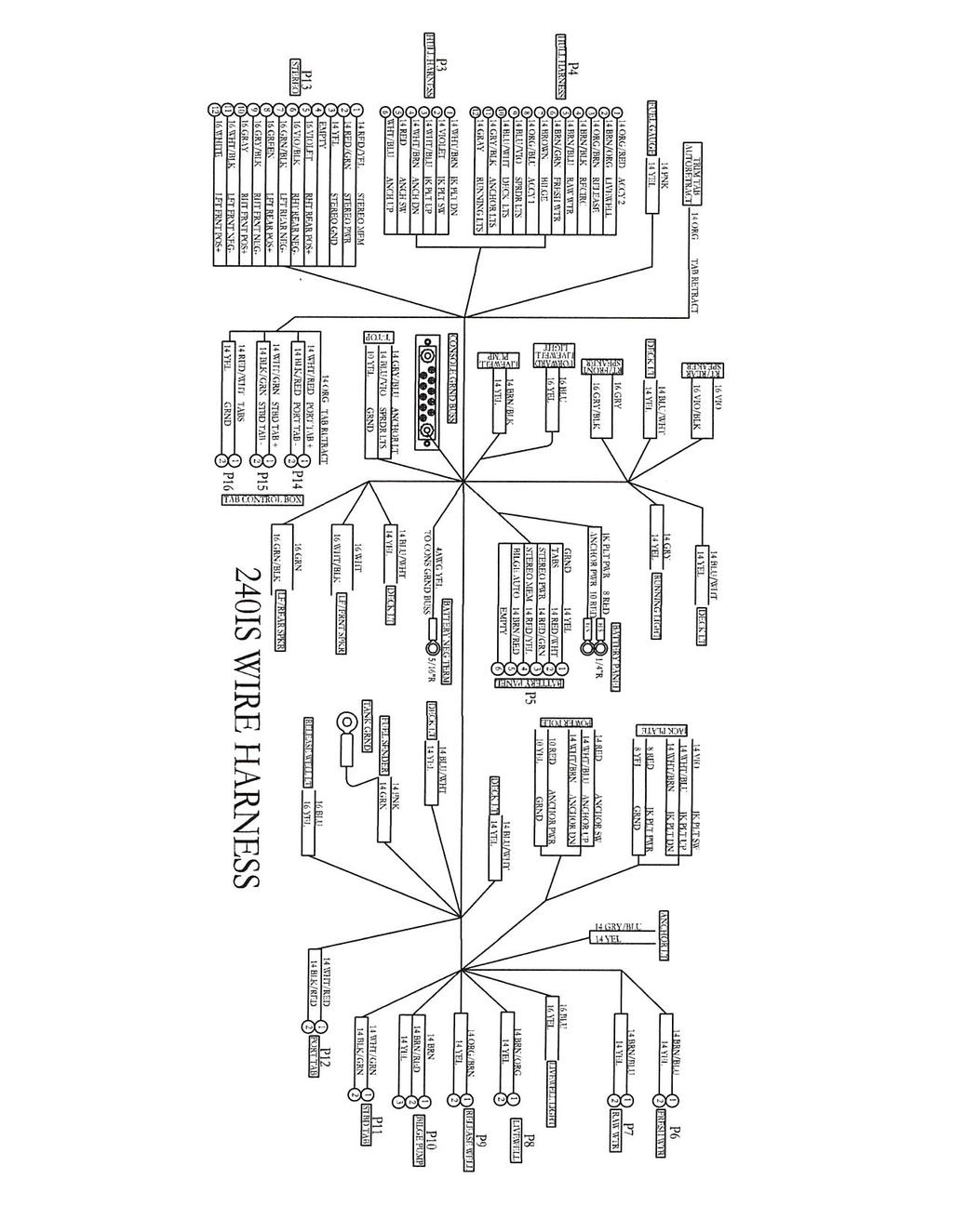
14 Place the nozzle firm against the side of the opening to prevent static discharge Begin fueling. When the tank is full, stop fueling. Remove the fuel nozzle. Install the fuel cap. Check the area for fuel odors. Warning: If fuel odors are detected, do not start the engine! Check to make certain there are no leaks or system problems before starting the engine. Warning: Do not fill the fuel tank while the engine is running. Do not allow smoking or open flames within 50 ft. of the fueling area. Fuel is very flammable. To prevent damage to the engine, use only fuels without harsh additives or alcohol. Refer to your engine owner s manual for specific fuel requirements. 4.5 Fuel System Maintenance Regularly inspect the fuel system components. All lines, fittings, and bulbs should be flexible and not corroded. If fittings or other components are found to be cracked, they should be replaced at once. If you use your boat infrequently or do not use it for an extended period of time, a fuel conditioner should be added to a full tank of fuel to prevent fuel deterioration and damage to the fuel system. 4.6 Fuel Filters A fuel filter is installed in the transom area of your EdgeWater 240IS. This is a fuel/water separator type of filter and is designed to prevent water from entering your engine. The fuel filter element is a spin-off type element. At a minimum, this element should be replaced at the beginning of every boating season. Always carry a filter wrench and spare filter of the type supplied on your boat. 5/Electrical Systems 5.1 General Your EdgeWater 240IS operates on a 12 volt DC system, similar to your automobile. The battery or batteries are typically lead acid type and require similar maintenance to your car s battery. An electrical schematic is included in the Appendix for specific location of electrical components. 5.2 Panel Switches Your EdgeWater 240IS is equipped with panel mounted breakers. On the 220IS, switches are provided for the navigation lights, decklights, manual bilge pump, livewell, raw water pump, freshwater pump, spreader lights for t-top, fishwell pumpout (not applicable), and four accessory switches. A wiring diagram is included with this manual to assist you in troubleshooting the boat s electrical system. Please note that the accessory circuits are each protected by a circuit breaker. 12
15 Check that the requirement of any device you install does not exceed the rating of the circuit breaker being used. When equipped with dual batteries the boat will have a battery selector switch which provides isolation for each battery and also provides the ability to have a back-up in case of a dead or weak battery. When in port and running accessories such as entertainment equipment or pumps, the selector switch should be set on 1 or 2. When leaving the boat unattended, the selector switch should be in the OFF position. Current is supplied to the automatic float switch and the bilge pump even when the battery selector switch is in the OFF position. Avoid running the selector in the both position, as the weak battery will drain the charged battery, leaving you with two weak batteries. Instead, start the engine using the charged battery. Once the engine is running, turn the battery switch to the both position to charge both batteries. 5.3 Electrical System Maintenance At the beginning and end of each season the exposed electrical components of the switch panel should be sprayed with a non-conductive rust/corrosion inhibiting spray. Light bulb connections and running light connections should be covered with a non-water soluble lubricant. Care must be taken not to get grease on the glass portion of the lights as it will cause them to overheat and burn out. Inspect all wiring for breaks, loose terminals and sound insulation. Replace worn or deteriorated components. Check the electrolyte level in the batteries regularly and fill with distilled water, as necessary. DO NOT OVERFILL. 6/Raw Water & Freshwater Systems 6.1 General The standard raw water system consists of a high speed pick-up, located on the transom, a pump, and one or more livewells and washdowns. 6.2 Livewell Operation The livewell is filled by a low maintenance centrifugal pump installed in the bilge. The pump is controlled by the livewell switch on the control panel. To operate properly, the valve inside the livewell must be adjusted to provide an even flow in and out of the livewell. Too much and it will be more than the drain can handle, too little and the water will not get the proper circulation. The valve should be turned counterclockwise to open and clockwise to close. There is a standpipe in the livewell drain to regulate the height of the water level. The livewell drains through a hose connected to a valved thru-hull fitting on the boats transom. To completely drain the livewell, open the transom valve, remove the standpipe and allow the water to drain overboard. A diagram of the raw water system is included with this manual. 13

16 6.3 High Pressure Washdown The washdown system is comprised of a diaphragm pump mounted on the hull inside the starboard side transom access door and a washdown fitting to attach a hose. The pump is controlled by the washdown switch on the control panel. The diaphragm pump is fed through the same thru hull and high speed pickup as the livewell pump. The washdown hose outlet is located on the starboard side of the transom area. With an attached hose, this system can be used to wash debris from the boat. The switch should be turned on immediately prior to use and turned off when not in use. When activated, the pump s pressure switch will automatically control the pump. It is normal for the pump to cycle on and off in response to flow rates and water demand. Always turn off the high pressure washdown pump switch when leaving the boat unattended. 6.4 Freshwater System The freshwater systems diaphragm pump is mounted on the inside of the console access locker. The pump is controlled by the freshwater switch on the control panel. The diaphragm pump is fed by a freshwater tank located in the fuel tank cavity. The shower head assembly is located on the starboard side of the transom area. The freshwater switch should be turned on immediately prior to use and turned off when not in use. When activated, the pump s pressure switch will automatically control the pump. It is normal for the pump to cycle on and off in response to flow rates and water demand. Always turn off the freshwater pump switch when leaving the boat unattended. 6.5 Raw Water System Maintenance The following checks should be made periodically to assure your system operates properly: Periodically spray pumps with a protective silicone solvent to reduce corrosion. Periodically check in-line filter to remove any collected debris. Fishboxes and livewells should be drained and cleaned after each use. Periodically check hoses and connections for signs of deterioration. Periodically check water tank straps for looseness. 14
17 7/Drainage System 7.1 General All water drains from your EdgeWater 240IS by gravity. Your boat is self-bailing at rest. It is important to check drains frequently to make sure they are clear and free flowing. Review the schematic in the Appendix and become familiar with the location of each thru-hull drain. 7.2 Drain System Maintenance Essential tasks must be done periodically to maintain your boat s ability to drain in adverse conditions. Clean cockpit drains to remove debris or other foreign objects which could prevent boat from draining properly. Check bilge area for debris and foreign material, which can cause automatic switches to malfunction. Flush drains to keep free flowing and clean. 7.3 Cockpit Drains Your EdgeWater 240IS drains aft thru two cockpit drains located at the aft deck area. The deck is designed to take water from other draining parts of the boat such as the forward lockers and cupholders and drain it overboard. These should be checked periodically to make sure they are clear running and free from debris. When washing the boat down after use, use a hose nozzle with a high pressure stream to make sure they are free running. 7.4 Transom Bilge Your EdgeWater 240IS has a hull bilge where the raw water pump and automatic bilge pump are located. The bilge pump is designed with an internal float so that it automatically turns on if the water in the sump rises, or it may also be activated by a momentary switch on the panel. This pump should be periodically checked to make sure it is working properly and that the drain screen is clear. To check the pump, squeeze the pump sides and lift it from the base, which is fastened to the hull. The screen will be easily seen and if there is debris, it may be cleaned and replaced. Replace the pump assembly and check its operation by turning on the momentary switch on the helm switch panel. When the boat is out of the water it may be drained by a thru hull drain located at the bottom of the transom. This drain has a brass plug that may be removed with a ½ wrench. This plug should be periodically checked for tightness. Note: The bilge sump area should be checked for oil before operating the bilge pump. The discharge of oil from a bilge area is illegal and is subject to a fine. The Federal Water Pollution Control Act prohibits the discharge of oil or oily waste into or upon the navigable waters of the United States or the waters of the contiguous zone if such discharge causes a film or sheen upon, or a discoloration of the surface of the water, or causes a sludge or emulsion beneath the surface of the water. Violators are subject to a penalty of $10,
18 7.5 Locker Drains On the 240 IS, there is a forward anchor locker which drains directly through the hull. There are also bow fishwell and storage lockers. The starboard locker drains onto the floor, the port drains overboard. These lockers are close the waterline of the boat. It is possible that under certain conditions sea water may enter the lockers. This is normal and no cause for alarm, some water may remain in the rear most part of the lockers. If you are using the port fishwell locker for something other than fish & ice, (i.e. dry storage), use the rubber plug provided in the owner s bag to prevent sea water entry. 7.6 T-Top Drain (optional T-Top) There are small holes drilled into the bottom of the T-top to facilitate the removal of any water that might inadvertently get into the structure. These should be periodically checked, especially during freezing weather, as trapped water could freeze, expand, and damage the hard-top. 8/Safety Equipment 8.1 Required Safety Equipment Contact the U.S. Coast Guard Boating Safety Hotline at , or to obtain a pamphlet on the latest required and suggested safety equipment. The Coast Guard Auxiliary also offers Courtesy Examinations to help ensure your boat is properly equipped. The following is a list of required safety equipment to be aboard your boat. This may be modified from time to time and it is suggested that you contact the U.S. Coast Guard Boating Safety Hotline at or pick up a copy of the latest Federal Requirements and Safety Tips of Recreational Boats pamphlet. Personal Floatation Devices (PFD s) These must bear a tag that they have been approved by the U.S. Coast Guard and must be in serviceable condition. They must also be of the appropriate size for the wearer, i.e. for children there must be children s life vests on board. Many states now require children to wear PFD s at all times. You should check with your state to determine the proper requirements. You should maintain at least one Type I, II, or III PFD for each person on board, plus one throwable device, a ring or boat cushion, Type IV. Visual Distress Signals These are now required in virtually all waters of the United States. If in doubt, please check with the U.S. Coast Guard Boating Safety Hotline at for a specific answer. Pyrotechnic Visual Distress Signals These must be U.S. Coast Guard approved, be in a serviceable condition, and be readily accessible. They each have a service life date and are not counted beyond this date. These types include both hand held flares and aerial flares. Sound Signaling Device You must have an efficient means of making a proper sound signal in the event of distress or poor visibility. This may be a horn, whistle, or bell. 16
19 Navigation Lights These come with your EdgeWater and meet U.S. Coast Guard requirements. It is important that you periodically check to make sure they are in working order. It is very important these be checked prior to any cruise which will keep you on the water after dark. Fire Extinguisher A fire extinguisher is standard on all EdgeWater boats. These require regular inspection to make certain they are ready for use. Questions may be directed to the U.S. Coast Guard Boating Safety Hotline at , or You should, as part of routine boat maintenance, check to make sure your extinguisher is still operable. Never discharge your fire extinguisher to see if it still works. This will cause it to lose pressure. If it is accidentally discharged or if it is used on a fire, replace it immediately. 8.2 Suggested Safety Equipment - Inshore Suggested safety equipment, over and above the required equipment is: First aid kit and manual Boat hook Tool kit An adequate number and size of line should be on the boat. Bow lines should be at least 1/3 longer than the boat s length and stern lines at least as long as the boat. When operating in areas with unusually high tidal range, this should be lengthened. The minimum size line for a small boat is 3/8 diameter 3 strand nylon. Refer to one of the listed references in the Appendix for a complete discussion on line size relative to boat length. Waterproof flashlight, with good batteries Spare batteries Spare boat keys Binoculars Tow line. This should be a minimum of 50 long with at least one size increase over the boat s mooring lines. Day/Night visual distress signals Local charts and compass Properly sized anchor and line Fenders of the proper size Always carry water, even for a 10 minute cruise. 8.3 Suggested Safety Equipment Offshore In addition to the required equipment, and the suggested inshore equipment, there is additional equipment which is prudent to have when venturing offshore. No matter what the conditions at the start of the trip, the situation can change rapidly and all your equipment and skill can be required to safely bring your crew home to safety. VHF radio 17
20 A supplemental, portable VHF is also a good back-up Sunscreen Spare propeller and the knowledge of how to properly change it, if required Extra clothing for changeable weather conditions Spare anchor with sufficient line for the water depth Mirror Charts 9/Safe Operation 9.1 Pre-Cruise Check List Check provisions. Make sure you have plenty of water in the event you have a problem and are delayed. Check the weather forecast. Avoid sea conditions that are beyond the experience of yourself and your crew. Do you have the correct safety gear aboard and is it in good working order? Make sure all fire extinguishers are in good working order. It is advisable to carry jackets or foul weather gear in the event of adverse weather conditions. Your EdgeWater 220IS is equipped with a maximum capacity rating plate permanently affixed to the helm area of your boat. It will provide information regarding the maximum number of people you can safely have aboard, the maximum amount of weight the boat can safely carry, and the maximum horsepower your boat was designed to handle. Do Not Overload your boat. Before Starting the Engine Determine if the trip can be safely made by checking the weather. Are all the proper boat and personal documents on board? Check operational equipment, such as running lights and horns to make sure they are on board, and operable. Make sure there are enough provisions for the cruise. Leave a float plan with someone who can notify authorities in the event you do not return in the allotted time. Double check the fuel and engine oil levels. Set the battery switch for the proper setting. Check the emergency stop lanyard to see if it is properly attached, and that the shift lever is in the neutral position. Check fuel and oil to make sure you have more than enough for the planned trip. Remember the rule of thirds: 1/3 out, 1/3 back, and 1/3 in reserve. 18
21 After Starting the Engine Upon initial start-up, make sure to follow the manufacturer s recommendations for engine break-in Check to be sure there is a tell-tale water stream exiting the engine. Check the gauges to determine if everything is nominal. Check to make sure everything is secure and properly stowed away; remember the boat s movement is dynamic and anything that is loose will become a hazard at the worst possible time. Have a great time on the water Remember that the captain is responsible for the safety of the crew and passengers and for his/her boat s wake damage. Never operate the boat while under the influence of alcohol! Make sure someone else on-board knows how to operate the boat in the event you are injured and unable to operate the boat. If you are operating the boat for the first time, make sure you follow the engine manufacturer s break-in recommendations. This will assure proper break-in and reduce the possibility of engine problems. 9.2 Basic Rules of the Road The following is not intended to be a comprehensive course in seamanship and rules of the road, but instead an introduction. It is strongly recommended that a boating safety course be taken from your local Coast Guard Auxiliary or local Department of Natural Resources. There are also many good reference books in your local library as well as numerous sites on the internet. Remember, paddle boats, sailboats and other vessels (such as barges) which are unable to maneuver, always have the right of way over powerboats. Sail boats, when under power, are considered motor boats. However, always boat defensively. Aids to Navigation Along the coast lines and in navigable inland waters, aids to navigation have been placed by the U.S. Coast Guard. These have been placed for the boating public s safety. Please become familiar with them and learn to use them to make your boating safer and more fun. 19
22 Federal Waterways Marking System Aids Lateral Aids as seen from Seaward (portside green) Daymark Can Buoy Lighted Buoy (green light) Lateral Aids as seen from Seaward (starboard side red) Daymark Nun Buoy Lighted Buoy (red light) 9.3 Safe Operation Getting Underway After clearing the dock, make sure the power trim (if so equipped) is trimmed down. (This will bring the boat up on plane more quickly and easily.) Give the engine sufficient throttle to bring it to plane briskly, then back down to the cruising speed of your choice, based on the sea conditions and your planned activity. After coming on plane, raise the trim to a point where the engine is level with or slightly above the plane of the water. This is usually with the bow at about 3 o to 5 o above level. This will provide the smoothest, most economical operation. Keep a constant vigil for other boats and watercraft and be prepared to give way, or slow down, if necessary. (We suggest you enroll in a boating safety course offered by the U.S. Power Squadron or the Coast Guard Auxiliary.) When coming off plane, allow the engine to come back to an idle speed until the boat slows down. Shift to the neutral position. Never allow anyone to sit on the gunwale while the boat is moving! While underway keep a constant vigil for other craft that may be approaching, the gauges on your boat, location of passengers and the general sound and feel of your craft. Often, a change in the way the 20

23 engine sounds or the boat feels will presage a problem. Your early attention may prevent a more serious problem. If you should strike an underwater object, bring the throttle to neutral and stop the engine. Inspect the lower unit for damage. If none is apparent, proceed as before but heighten your awareness of the engine and its operation to make sure a problem has not gone undetected. 9.4 Towing or Being Towed Sooner or later your will have the misfortune of having to be towed in or needing to tow someone back to a safe landing. It is important that this be done properly so that a difficult situation does not become worse. This comes under a longstanding, unwritten law of the sea that one boater will aid another in time of distress. The 1971 Boating Safety Act grants protection to those assisting others at sea as Good Samaritans and absolves them of civil liability rising from the aid being provided. When being towed, it is best to have a line passed from the tow boat to the one being towed, assuming the towing boat has a line of adequate size and length. The tow boat should also tow the disabled vessel from as close to amidships as possible. This reduces the tendency to yaw. If possible, the towing boat should use a bridle attached to the two stern ski tow eyes. The vessel being towed should attach the tow line to the bow eye that holds the boat onto the trailer. This provides an optimal tow position and a strong tow point. Have the occupants of the boat being towed sit aft of amidships, but not all in the stern. Attention should be given so the boat remains balanced and on an even keel. Some boats tow better with the engine tilted out of the water, others need the engine to act as a rudder to be able to maintain a straight line. Start with the engine tilted. If that does not work well lower the engine until it is about perpendicular. You should never attempt to plane off the boat being towed. 9.5 Stopping the Boat Gradually bring the controls back to the low forward position and allow the boat to gradually slow down. After the boat has dropped into the displacement mode, shift to the neutral position. If you have been running the boat hard for some time, allow the engine to idle for several minutes to gradually cool down. After docking and securing the boat, raise the trim tabs to the fully upright position and turn off the ignition. 9.6 Docking Safe docking keeps your boat from being damaged and is an indicator of a capable and knowledgeable captain. There are many docking maneuvers, which will be done while boating; only the basics will be discussed here. Several constants to always use as guides while docking: Perform docking at idle or no wake speeds. Always try to come into wind or current, whichever is stronger. This allows you to use the natural forces on your boat to act as a natural brake. The skipper is free to use the boat s power to control speed and direction. 21

24 The approach to the dock should be at roughly a 45 o angle, when possible. This approach angle allows the captain to bring the bow close to the dock, and then to use reverse, while turning the wheel toward the dock, to bring the boat to a safe, controlled stop. Never approach a dock on plane. Even after reducing engine speed, the wake will push the boat uncontrollably into the dock. 9.7 After Operation Refill the fuel tank and engine oil, if yours is a two-cycle engine. A full fuel tank is less subject to condensation and therefore, less fuel problems. If you will be leaving the boat for an extended period, use a good fuel stabilizer. Each engine manufacturer makes their own and proper use will avoid many fuel related and lay-up problems. Remember, always follow the manufacturer s recommendation. If the boat is to be left in the water, make sure it is secure and free to properly accommodate any tide. Turn off all electronics and leave the battery switch in the off position. Remember, the bilge pump will operate properly even with the battery switch turned off. On a comforting note, your EdgeWater 225C is fully self bailing and unsinkable. Proper precautions, however, are always prudent. 9.8 Trailering Your Boat Note: If you have doubts or questions about your tow vehicle or towing, contact your dealer. Before going on the highway, make sure your tow vehicle and trailer meet the local regulations for trailers and towing in your state. Before leaving the driveway make sure the lights on the trailer are operating properly. If necessary, get a second person to make sure of the operation. At least once a season, check and repair/replace the trailer wheel bearings. The trailer should be adequately sized for your boat. Allow about 10% above the maximum boat weight for trailer capacity. Make sure your vehicle is properly equipped to handle the load. This includes engine, hitch, frame, brakes, transmission cooler, and vehicle capacity. Securely attached the boat trailer to the vehicle hitch, hook the safety chains and and cross them under the hitch and check the lights to ensure they are hooked up and working. If you are new to trailering your boat, it is best to practice before actually getting in a situation where you are not sure of your ability. If possible use a trailer without a boat to practice with as you can see the trailer s movement without the boat. Also, your vision will not be impaired by the boat s presence. When going forward, remember that your trailer turns inside the tow vehicle, therefore the tow vehicle must start the turn slightly later than without the trailer. This allow the trailer to turn inside the tow vehicle radius without leaving the roadway. 22
25 When backing, remember, the bottom of the steering wheel will move in the direction the trailer will ultimately go. Backing consists of two parts, breaking the trailer by turning the vehicle s backward motion in the opposite direction from the ultimate trailer direction, then following the trailer toward the correct direction with the tow vehicle. It is prudent to go to a large paved area with little traffic to practice these maneuvers before attempting them on the boat ramp. Remember to check to see if the tow ball is the same size as the trailer coupler. Never use a different size. 9.9 Launching Your Boat When you arrive at the ramp, prepare your boat before getting in the ramp line. Make sure the hull plug is in place. Place a line on the bow and stern cleats to be at the dock ready. Have fenders out and on the proper side. Raise the engine so it will not be damaged during launching. Make sure the battery switch is in one of the on positions, and the boat key is in the ignition. Remove any tie-down straps. If someone is with you, hand them the free end of the bow line and have them follow the trailer as you enter the ramp. Back the boat into the water until it barely floats. Remove the winch line. The boat should now come free with a gentle tug on the bow line. Lower the engine, pump the fuel bulb until firm and crank the engine. Let it idle for a few minutes to warm up before getting under way Retrieving Your Boat There are several ways to retrieve your boat. The method described herein requires two persons. Drop someone off to back the trailer into the water, or do it yourself. If doing it yourself, make sure you make it easy and safe to exit the boat after it is loaded onto the trailer. Back the trailer into the water until the bunks are completely submerged, or until the middle roller is just touching the water. (This depth should provide enough to float the boat until the last minute and yet provide enough resistance from the trailer to stop the boat short of the winch stand.) Drive the boat onto the middle of the trailer. This is assuming it is a trailer designed for drive on. Speed should not be over one or two knots. Fast enough to maintain steerage but slow enough to be easily controlled. Once the boat has touched the trailer, a little forward throttle should secure the boat on the trailer and allow you to put the engine in neutral and have the winch line attached to the bow eye. The boat should now be easily winched onto the last several feet of the trailer. When properly done, this method is easy, safe and will not harm boat ramps by powering away the soil from the base of the ramp. 23
26 10/Routine Maintenance 10.1 Exterior Hull and Deck Fiberglass When you remove the boat from the water, clean it as soon as possible. Dirt, debris and grime will come off easier while it is still wet. Use a brush and biodegradable boat cleanser. Stubborn areas may be cleaned with a non-abrasive cleaner. Harsh abrasives and chemical cleaners are not recommended as they can damage the gelcoat, shorten its life, and make it more susceptible to stains. When used in saltwater, the boat should be washed after each use. NOTE** Do not use any cleaners containing ammonia or with extremely high or low PH levels as this will effect condition of gelcoat. The hull should be waxed periodically, at least once a year, with a high quality wax. This will keep it shiny looking and help prevent chalking and aging. The wax will also make it easier to keep clean by closing the pores that trap the grime. If the boat is to be kept in freshwater or saltwater for an extended period, a proper barrier coat and bottom paint must be applied to prevent possible Gel Coat blistering. Do not wax non-skid areas. It could make them slippery and increase the possibility of injury. Stainless Steel Hardware The stainless steel hardware of your boat should be cleaned and washed after each boat use, especially in salt or polluted water. While it is stainless it is not stain-proof. If it is not cleaned, it can develop surface rust stains. It can be protected with a high quality automotive or boat wax. It can also be protected with a commercial metal cleaner and protectant. Anodized Aluminum The aluminum can be maintained with a regular washing with soap and water. Otherwise it can develop a surface corrosion, which can penetrate the anodizing and attack the aluminum underneath. If badly scratched, it can be repaired with an aluminum or silver paint. Chrome Hardware Use a good metal polish and protect with wax. This should be done every couple of months or as soon as you notice any finish deterioration. Plexiglas Do not use products with ammonia on your Plexiglas windscreen. It can mar the surface and reduce its transparency. A mild soap and water or non-ammonia cleaner will work well. In addition to ammonia, cleaners should not be used which contain solvents, acetone, or alcohol. 24
27 Upholstery Soap and water should be periodically used to clean the vinyl. Vinyl protector products can make the seats slippery, which may not be desirable. When cleaning the vinyl, be gentle. Do not use cleaners that contain ammonia, acetone, strong solvents, or powdered abrasive cleaners. They can damage and shorten the vinyl s life. Sump Area Your EdgeWater has a bilge area in the after part of the boat. This can be maintained well by periodically using a boat bilge cleaner. Follow the directions carefully Engine If you have a new engine with a built-in flushing device, the engine may be flushed without cranking. If the engine does not have a built-in flush device, one may be purchased to fit. To flush the engine, after connecting a water hose to the proper connection, turn on the water. Put the engine control in the idle position and crank the engine. Only let it run a couple of minutes. The gear case is water-cooled and is not designed to run out of the water for extended periods. Do not crank the engine without water running. Water acts as a coolant and also a lubricant for the water pump. Do not rev the engine when flushing; idle speed is sufficient! The exterior of the engine will respond well to a good quality wax. This should be re-applied every several months as the marine environment is a very harsh one and the constant sun exposure will deteriorate your motor s finish. Consult the engine manufacturer s owner s manual for specific instructions. In areas where there is a conflict between this manual and the engine manufacturer s manual, the engine owner s manual will take precedence. 11/ Exterior Equipment 11.1 Anchor Locker The anchor locker on your new EdgeWater 240IS has been designed for a danforth style 8 S anchor. On the 240IS the anchor locker is located forward on the centerline. Before using the anchor for an extended period or overnight, make sure the free end of the anchor line is shackled to the boat s forward eye. On the 240IS your anchor line should have a shackle attached to the free end which is then attached to the eye in the anchor locker at all times. Remember, your anchor line should be a minimum of 7 times the depth in which you routinely operate. 25

28 Your EdgeWater 240IS should have a minimum of 150 to 200 feet of ½ three strand nylon line. If you routinely venture offshore, remember the 7 times depth rule. This may sound like a lot but if your engine fails in 100 feet of water, maintaining your position will be very important to being recovered Swim Platform (optional) If your EdgeWater 240IS is equipped with the optional swim platform, there are several important things to remember for safe use and operation of this useful option. Always shut down the engine if persons will be using the platform. Do not just settle for the engine being in neutral. Make sure the folding ladder portion has been properly stowed before getting underway. 12/Seasonal Maintenance 12.1 Engine Refer to your engine manual for any specific information pertaining to your engine. For the fuel system, add a fuel stabilizer to a full fuel tank as per the stabilizer s instructions. Run the engine for a minimum of 10 minutes to allow the fuel stabilizer to reach the engine. Wax the engine exterior. Remove the engine cowl and spray the engine s powerhead with a non-conductive lubricant spray. Do not spray directly on joints that are lubricated with grease as some lubricant sprays may dissolve grease. Grease all external zert fittings on the engine and steering system. Use a grease that is consistent with engine manufacturer s recommendations. Change the engine lower unit lubricant. This will remove contaminants that may have built up throughout the boating season. This is also a good time to check for lower unit seal problems. If there is a leak, have it repaired by your dealer. Remove the propeller and grease the propeller shaft. Inspect the shaft and propeller for unusual wear or signs of deterioration Hull Wax the entire boat. The hull will maintain its factory delivered luster much longer if waxed at least once a season. The inside of the boat, which is subject to the sun s direct rays, will also respond well to a good coat of marine wax. DO NOT wax the non-skid surfaces. Remove the hull plug so the sump area can breathe. 26
29 12.3 Storage It is best to store the boat inside, however if inside storage is not available, use the following guidelines in order of preference Under awning with no boat cover Outside under a boat cover. (Boat cover should allow ample ventilation and be removed periodically to allow moisture to disapate avoiding mildew growth and staining Trailer Check the wheel bearings for water. Clean and repack/replace as necessary. Check the tires for proper inflation. Try to store the boat and trailer with the bow slightly elevated so it will drain. If possible, cover the boat so that the sun will not deteriorate and tree sap and other environmental hazards will not damage the deck or upholstery. If covered, make sure to let air circulate so mildew will not build up. If in a high snow or rain area, make sure to properly support the cover to sustain and shed the load. 27
30 Appendix 240IS 28
31 30
32 Hydraulic Steering System 31
33 32
34 33
35 34
36
37
38
39
40
41

42 BAYSTAR SEASTAR HYNAUTIC H Y D R A U L I C S T E E R I N G S E L E C T I O N G U I D E M A R I N E
43 Boating safety is everyone's responsibility. As a boater, you are responsible for having all required safety equipment, for operating your boat safety and for ensuring the safety of those on board your vessel as well as those sharing the waterways. Boaters exercising courtesy and common sense will not create a hazard, threat, stress or an irritant to themselves, to others, to the environment, or to wildlife. 1. Wear an approved Personal Flotation Device (PFD) 2. Read your owner s manual. 3. Attach engine stop switch securely to your body or PFD. 4. Respect the speed limits and other boating restrictions. 5. Be cautious and courteous. 6. Navigate with care. 7. Understand the behaviour characteristics of your vessel that might result from unexpected manoeuvres, such as sudden deceleration, high-speed obstacle avoidance, and other speed related issues. 8. It is good boating practice to rinse down your boat and exposed steering equipment with clean, fresh water after each use. DO NOT use corrosive materials on SeaStar products. Become informed and stay informed! "Take an accredited boating safety course" Notice to Boat Manufacturer or Installer Throughout this publication, Warnings and Cautions (accompanied by the International Hazard Symbol ) are used to alert the manufacturer or installer to special instructions concerning a particular service or operation that may be hazardous if performed incorrectly or carelessly. Observe Them Carefully! These safety alerts alone, cannot eliminate the hazards that they signal. Strict compliance to these special instructions when performing the installation and maintenance plus common sense operation are major accident prevention measures. DANGER Immediate hazards which WILL result in severe personal injury or death. WARNING Hazards or unsafe practices which COULD result in severe personal injury or death. CAUTION Hazards or unsafe practices which COULD result in minor injury or product or property damage. NOTICE Information which is important to proper installation or maintenance, but is not hazard-related. NOTICE Help protect your boating environment by ensuring that all used oil is disposed of properly. Cover photo provided by Regulator Marine. Boat model: 32 Classic.
44 TABLE OF CONTENTS The BayStar & SeaStar Hydraulic Steering Systems. BayStar Outboard Steering System. 1-1 BayStar Compact Application Guide 1-5 SeaStar Power Assist 2-1 SeaStar Outboard Steering Systems. 3-1 Front Mount Steering System 3-2 SeaStar Pro Steering 3-9 Outboard Catamaran 3-12 Side Mount Steering System 3-13 Splashwell Mount Steering System 3-16 SeaStar Sterndrive Systems. 4-1 SeaStar Inboard Steering Systems (Power & Sail) 5-1 Hynautic 3-Line Inboard Steering 6-1 Application Guide 6-3 Hynautic Seal Kits 6-6 Crossover Hynautic to SeaStar Steering 6-7 SeaStar Power Steering 7-1 Hynautic Trim Tabs 8-1 SeaStar/Hynautic Helms General 9-1 SeaStar Standard/Rear Mount Helms 9-4 SeaStar Tilt/Sport Tilt Helms 9-5 Hynautic Helms 9-7 SeaStar Hose, Tubing, Fittings, Accessories & Tools 10-1 Outboard Hose 10-2 Inboard/Sterndrive Tubing 10-6 Additional SeaStar Steering Station or Autopilot Kit 10-8 Fittings & Fitting Kits 10-9 Liquid Tie Bar alignment Valve Tools Torque Data Sheets Hydraulic Fluid 11-1 SeaStar and Hynautic Volumes and Capacities Authorized Distributors 13-1 Retailers Teleflex Canada Limited Partnership Warranty ii SEASTAR and BAYSTAR Hydraulic Steering Systems i
45 BayStar and SeaStar Hydraulic Steering Systems The BayStar Hydraulic Steering System is designed to add safety, reliability and comfort to single station outboard powered boats to a maximum 150HP (Total). The SeaStar Hydraulic Steering System is designed to provide that extra margin of muscle when needed. The SeaStar system easily handles Outboards, Sterndrive and Inboard boats. System selection, installation and service is substantially simplified with just three major components helm, cylinder and tube or hose. SeaStar has a comprehensive range of available cylinders to handle the variety of Outboard, Sterndrive and Inboard steering applications. These are suitable for both pleasure and commercial applications. Extra steering stations and/or autopilots are easily added. SeaStar hydraulic steering is a total commitment to quality, performance and simplicity. BayStar & SeaStar, the hydraulic steering systems that are; Easy to install Only three components: helm, cylinder & tube or hose Compact and attractive helm design Variety of helm mounting configurations Simple tube/hose fitting connections Clear, complete installation instructions Easy to fill and purge Engineered bleed fittings on the cylinders A helm and lock valve design that enhances air removal A no-mess filler device A filling and purging time of normally less than 30 minutes Easy to check for proper installation Easy purging check via filler device No searching for difficult-to-find air leaks Easy to turn Anti-friction piston points Designed to provide many years of service Precision built Heavy-duty bearings instead of bushings No corrosive materials exposed to marine environment Field replaceable helm and cylinder shaft seals A no-hassle warranty 2 years for pleasure use 1 year for commercial use (SeaStar) BayStar and SeaStar! Simply the best! ii Selection Guide
46 Teleflex Hydraulic Steering Our manual hydraulic steering systems are simple and efficient. The basic system consists of three main components; 1) the helm pump, 2) the cylinder, and 3) the hose or tubing required to connect the cylinder to the helm pump. These basic components are necessary in all applications. However as the system variables increase (ie: multiple engines, rudders, steering stations and autopilots), additional components may be required. 1. The Helm Unit. The helm pump is an axial piston pump specifically designed for manual steering. It has a built-in lock valve to prevent the steering load from feeding back to the driver. The lock valve will not allow the rudder or drive unit to move until you move it with the steering wheel. The lock valve section of the helm also includes a relief valve. This relief valve provides over-pressure protection for mechanical components and hydraulic hoses and fittings. 2. The Cylinder. The most important differences between the variety of steering systems available is the cylinder selection. Both BayStar and SeaStar systems have a cylinder for most steering applications. 3. Hoses and Tubes. Required to provide a path for the fluid to flow under pressure from the helm pump to the cylinder. The System: How it works The system is a two-line system. This makes operation very simple. 1) The steering wheel, which is attached to the helm pump, is rotated in the desired direction (ie: a turn to starboard or clockwise rotation). 2) Oil is pumped out the corresponding port from the rear of the helm into the starboard line and then into the cylinder. 3) This causes the cylinder rod, which is attached to the vessels rudder or drive unit, to move (ie: rod moves to port) thus causing the vessel to alter course. 4) Oil displaced from the opposite end (ie: the port end) of the cylinder flows (ie: into the port line) back to the helm pump. 5) For steering in the opposite direction, simply turn the helm the other way. 6) When no course corrections are required, the integral lock valve holds the rudder or drive unit stationary. SEASTAR and BAYSTAR Hydraulic Steering Systems iii
47 Selecting the System The objective is to match the steering system to the requirements of the vessel. This depends on four things; 1) hull type (ie: planing or displacement), 2) type of propulsion system in the vessel (ie: inboard, outboard, sterndrive, etc.), 3) the number of engines or rudders, 4) the total power of the engines (ie: Horsepower). Once the system and cylinder has been selected, the size of the helm pump is pre-determined. SeaStar systems also allow the following options to be specified; 1) the number of steering stations, 2) helm configuration (ie: standard or tilt helm), 3) additional features such as autopilots. Notes on Steering Response versus Steering effort Steering wheel effort is directly proportional to the number of wheel turns lock to lock. The number of wheel turns lock to lock is dependent on three things; 1) the volume of the cylinder, 2) the displacement of the helm pump, 3) the allowable movement of the rudder or drive unit. Less wheel turns lock to lock results in more steering effort. More wheel turns lock to lock results in less steering effort. However, additional factors that can influence steering effort are; 1) vessel speed, 2) rudder size, 3) unusual propeller selections, 4) hull type (ie: displacement, planing, etc.), and 5) improperly aligned counter balance skeg. iv Selection Guide
48 System Selection Worksheet How can we help? We have provided the following check list to assist you in choosing your Hydraulic Steering System. We invite you to make notes on this page as required. as appropriate. OUTBOARD Single up to 150HP UNDER 55mph Most economical system to meet my steering needs...page 1-1 Economical to meet my needs, PLUS less effort at the steering wheel than above...page 3-1, 3-9 Power Assist 'Automotive' Style, Feel and Comfort...Page 2-1, 3-1, 3-9 OUTBOARD Multiple up to 150HP combined total Most economical system to meet my steering needs...page 1-1 Economical to meet my needs, PLUS less effort at the steering wheel than above...page 3-1, 3-9 Power Assist 'Automotive' Style, Feel and Comfort...Page 2-1, 3-1, 3-9 OUTBOARD Single 150HP 350HP UNDER 65mph Most economical system to meet my steering needs...page 3-1, 3-2 Power Assist 'Automotive' Style, Feel and Comfort...Page 2-1, 3-1, 3-2 OUTBOARD Single 150HP 350HP OVER 65mph Most economical system to meet basic steering needs...page 3-1, 3-9 Recommended for Steering Comfort and 'Automotive' Style and Feel...Page 2-1, 3-1, 3-9 OUTBOARD Multiple over 150HP (including Catamaran and Liquid Tiebars) Most economical system to meet basic steering needs...page 3-1, 3-2 Recommended for Steering Comfort and 'Automotive' Style and Feel...Page 2-1, 3-1, 3-2 STERNDRIVE Single and Twin Most economical system to meet my steering needs...page 4-1 Power Assist 'Automotive' Style, Feel and Comfort...Page 2-1, 4-1 INBOARD Single and Twin Most economical system to meet my steering needs...page 5-1 Power Assist 'Automotive' Style, Feel and Comfort...Page 2-1, 5-1 Power Steering System...Page 7-1 My Steering Components Helm Model #... Cylinder Model #... Hose/Tube... Other... Autopilot Equipped Yes No Date Purchased... Boat: Make... Model... Length... Engine: Make... H.P.... Quantity... SEASTAR and BAYSTAR Hydraulic Steering Systems v
49 vi Selection Guide
50 CHAPTER 1 OUTBOARD STEERING BayStar hydraulic steering is brought to you by the manufacturers of SeaStar, the most trusted name in pleasure boat steering. BayStar allows you to install all of the safety, reliability and comfort of hydraulic steering onto your boats rated up to MAX. 150HP (Total). Combine this with the superior Teleflex Canada Limited Partnership design team, rigid ISO quality control and teamed with the finest materials and precision manufacturing BayStar continues the tradition bringing comfort and safety to boating. The BayStar steering system consists of a super low friction helm for smooth comfortable steering, a balanced cylinder featuring a compact design that fits most splashwells. For your convenience two lengths of 20 cut to fit tubing are supplies (2 x 20 length), two bottles of hydraulic steering fluid, and one fill tube for easy fill and purge. CAUTION NOTICE BayStar is ONLY applicable for single station steering. DO NOT use BayStar on smaller HP outboard engines that use wing nut type transom mount clamping screws. Tilt Helm HH4315 is available separately. Currently not available in kit form. HELM CYLINDER TUBING Typical BayStar Installation SEASTAR and BAYSTAR Hydraulic Steering Systems 1-1
51 OUTBOARD FRONT MOUNT Three easy steps to select your BayStar System: 1) Check helm dimension. Both the Standard and Tilt helms require a 3" (76mm) cut-out hole in the dash. STANDARD HELM PART# HH4314 5/8" NF THREAD 1/4" NPT FILL PORT 3/4" STANDARD 1/4" NPT PORTS (4) TAPER 4-5/8" (118 mm) 3-15/16" (100 mm) 7-15/16" (200 mm) 3" DIA. (76 mm) TILT HELM PART# HH4315 3" (76mm) 4.8" (122mm) 9.2" (233.5mm) NOTICE Comes with newly designed tilt mechanism " (61mm) 6.8" (173mm) 3.6" (91.5mm) " (89mm) 1.3" (33mm) 1/4" NPT PORTS (4) 1-2 Selection Guide
52 OUTBOARD FRONT MOUNT 2) Check the BayStar cylinder dimensions through the full trim/tilt range of the engine. IS THE SPLASHWELL WIDE ENOUGH? The HC4645H/47H/48H /58H require a 21" (534mm) Splashwell width. BAYSTAR CYLINDER PART# HC4645H/47H/48/H58H 2.625" (67mm) 21" (534mm) 3) Is there enough room in the splashwell for full engine tilt? Find the dimensions (A, B & C) of your splashwell. Check them against the minimum splashwell dimensions for full engine tilt for your engine and cylinder. MOTOR WELL DIMENSIONS required for BayStar front mount outboard steering systems A CYLINDER # OF A B C MIN. ENGINE MODEL NO. ENGINES CENTER DISTANCE C HC4645H/47H/ 1 21" (534mm) 6" (153mm) 5" (127mm) N/A 48H/58H 2 Twin engine applications not available at this time B NOTES: i) Ensure there is no interference between the BayStar cylinder rod and the splashwell boot or engine controls & cables. ii) Dimensional restrictions also apply to external motor mount brackets. iii) Ensure dimension 'A' maintained through full trim/tilt range. iv) Maximum transom thickness 3" (76mm). v) Engines less than 70HP may require up to an additional 1" (25mm) of splashwell clearance. SEASTAR and BAYSTAR Hydraulic Steering Systems 1-3
 then purchase of a replacement Pivot Plate (noted on page 1-5) will be required.")
53 OUTBOARD FRONT MOUNT BayStar Steering Kits PID# HK4200A, HK4230A NOTICE HC4645H compact cylinder is included in both BayStar Steering Kits. If your engine requires the use of a cylinder other than HC4645H or HC4658H (refer to application guide on page 1-5) then purchase of a replacement Pivot Plate (noted on page 1-5) will be required. BayStar Steering kits come complete with everything needed for an install, (some engines require spacer kits and/or cylinder plate change, see application chart on page 1-5) the compact cylinder does not require the engine manufacturer drag link for connection. For your convenience two lengths of 20' cut to fit tubing are supplied with the HK4200A and two lengths of 30' cut to fit tubing are supplied with the HK4230A kit. BayStar Steering Kit (HK4200A) Includes: 1 x BayStar helm pump (HH4314) 1 x BayStar Cylinder (HC4645H) 1 x BayStar Tubing kit (HT4420H, comes with two 20' hoses) 2 x Hydraulic Steering Fluid (HA5430) 1 x Filler Kit (HA5438) BayStar Steering Kit (HK4230A) includes: 1 x BayStar helm pump (HH4314) 1 x BayStar Cylinder (HC4645H) 1 x BayStar Tubing kit (HT4430H, comes with two 30 hoses) 2 x Hydraulic Steering Fluid (HA5430) 1 x Filler Kit (HA5438) NOTICE HC4600 and HC4600H are no longer being made by Teleflex Canada, all seal kits and spare parts will be made available. If purchase of a new HC4600 or HC4600H is required, please purchase BayStar Compact Cylinder part# HC4645H/47H/48H/58H as per the application chart on page 1-5. If the cylinder that you are replacing does not include the letter H after the part number, you will need to reuse the fittings out of your old cylinder and/or purchase fitting kit # HF4201 (includes 2 of the old style bleed fittings). 1-4 Selection Guide
54 BayStar Outboard Compact Application Guide (BayStar Compact Cylinders HC4645/47/48/58) OUTBOARD FRONT MOUNT MFG YEAR MODEL CYLINDER NOTES FORCE 1985 DATE HP HC4645H HONDA 1992 DATE HP HC4645H 1998 DATE HP HC4647H 2001 DATE 150 HP HC4645H 2003 DATE BF135 HP HC4645H JOHNSON/ HP HC4648H EVINRUDE 1991 DATE HP HC4645H NOTICE Johnson 115 HP 2-stroke engines, required the pivot plate to be flipped. See note #4 below 1997 DATE 115 HP FICHT HC4658H DATE HP FICHT HC4645H 1998 DATE HP 4-Stroke HC4658H 1, 4 MERCURY/ 1984 DATE HP HC4645H MARINER NISSAN 1990 DATE HP HC4645H SUZUKI 1986 DATE 150 HP HC4645H 1996 ONLY HP N/A HP HC4645H HP HC4645H 1998 DATE Stroke HC4645H DATE HP 4-Stroke HC4658H 1, 4 TOHATSU 1990 DATE HP HC4645H YAMAHA 1998 DATE HP HC4645H DATE 60 HP HC4645H DATE HP HC4645H DATE HP 4-Stroke HC4645H 2000 DATE HP 4-Stroke HC4648H 1 YANMAR 1990 DATE HP HC4645H 1. Requires Spacer kit part # HO Engine clamp brackets must be cut or ground, and the engine through bolted onto the transom, or interference will occur, restricting engine trim and tilt. 3. Steering hook Yamaha Part # 63D D must be installed 4. Cylinder HC4645 may be used in these applications. The pivot plate will need to be flipped before installation. Instructions provided with Owner s Manual. The above engine applications are current through the revision date shown. For up-to-date engine applications go to: REVISION DATE: MAR. 10 TH 2006 NOTICE HC4645H compact cylinder is included in the BayStar Steering kits. If your engine requires the use of a cylinder other than HC4645H or HC4658H then please refer to the figure below for additional replacement pivot plate. HA4640 Use with cylinder HC4645H HA4641 Use with cylinder HC4647H HA4642 Use with cylinder HC4648H HA4643 Use with cylinder HC4658H SEASTAR and BAYSTAR Hydraulic Steering Systems 1-5
55 1-6 Selection Guide

56 CHAPTER 2 POWER ASSIST SeaStar Power Assist Pilot shown, available Summer, The Marine Industry is continually introducing heavier outboard engines, higher horse power engines, more aggressive propellers, bigger/faster boats... Boat operators are asking for increased comfort and lighter steering loads... These were the driving forces behind the design of SeaStar and SeaStar PRO Power Assist. This new and innovative product is highly recommended on any 200HP and above outboard application to give your boat the same, easy steering you are accustomed to in your car. Power Assist is also recommended for the following; Twin and Triple engine applications Bass Boats Power Catamarans Inboard powered cruisers without engine driven power assist. SEASTAR and BAYSTAR Hydraulic Steering Systems 2-1
57 POWER ASSIST How the System Works SeaStar P/A (Power Assist) steering uses an electronically controlled hydraulic pump to provide "Power" for your SeaStar Hydraulic Steering system. The SeaStar P/A system is comprised of two circuits: a hand operated manual system, which is the control element, and a hydraulic power pump, which is the working element. The manual system consists of a helm pump with internal relief and check valves, as well as a built in reservoir. Two steering lines and a compensating line which provide a routing for fluid to transmit through the system, and a steering cylinder which moves the steering device on the boat from side to side. The power system, is an electronically controlled hydraulic pump that boosts the fluid being sent from the helm pump to the steering cylinder (this will result in much easier effort at the wheel even when under heavy loads). A compensating line connects the P/A unit to the helm pump, allowing the P/A unit to share fluid with the helm reservoir. The SeaStar P/A is compatible with multiple steering stations, and with the use of an autopilot. In the event of a P/A power loss or failure the hydraulic system will automatically revert to a manual hydraulic system. HELM PUMP HELM PUMP STEERING LINES STEERING LINES COMPENSATING LINE COMPENSATING LINE Typical installations shown (please refer to you cylinder installation manual for proper hose installation diagrams). H1 C1 H2 C2 POWER ASSIST UNIT H1 C1 H2 C2 POWER ASSIST UNIT SEASTAR OUTBOARD CYLINDER TILLER ARM SEASTAR INBOARD CYLINDER 2-2 Selection Guide
58 POWER ASSIST SeaStar P/A Compatibility Chart NOTICE NOTICE NOTICE Use ONLY Teleflex products with the P/A unit as with ALL Teleflex systems. Failure to do so may void your warranty. The P/A is designed for use in recreational marine applications in conjunction with SeaStar Hydraulic Steering. Optimal performance will be obtained when used with SeaStar 1.4, 1.7 and 2.0 cu in (1000psi) helm pumps, or, 2.0 cu in (1500 psi) SeaStar P/A PRO Hydraulic Steering. SeaStar nylon tube may ONLY be used for the compensating line. DO NOT use SeaStar Nylon tube to plumb any other portion of the steering system. Plan ahead. There MUST be at least 4' (feet) of hose between the helm pump and power assist, or the power assist and the steering cylinder. SeaStar P/A PRO is NOT to be used with SeaStar Hydraulic Steering, performance will be compromised. ONLY use P/A PRO with a SeaStar PRO Hydraulic steering system and ensure that SeaStar PRO (1500 psi) hose is used to plumb the entire system. (Nylon tubing may be used for the compensating/return line ONLY. Specifications 8" 6.65" SEASTAR P/A 12VOLT, SEASTAR PRO P/A, 12 VOLT 12 Volts 1000 psi MAX System peak pressure (500 psi working load) SeaStar Standard 1500 psi MAX System peak pressure (500 psi working load) SeaStar Pro MAX Current Draw (at 1000psi) 55 amps Purple ignition wire MAX. current draw = 1 amp Typical current draw: Single outboard ~ 3 amps, average Twin Rudder inboard ~ 8 amps, average 10.5" 4.50" 4 x 0.25" SEASTAR P/A 24 VOLT. (SEASTAR PRO P/A IS NOT AVAILABLE IN 24 VOLT POWER). 24 Volts 1000 psi MAX., System peak pressure (500psi working load) MAX Current Draw (at 1000psi) 25 amps Purple ignition wire MAX. current draw = 1 amp Typical current draw: Single outboard ~ 1.5 amps, average Twin Rudder inboard ~ 4 amps, average WARNING DO NOT exceed peak operating pressure. 1000psi Standard, 1500psi Pro. SEASTAR and BAYSTAR Hydraulic Steering Systems 2-3
59 2-4 Selection Guide
60 CHAPTER 3 OUTBOARD STEERING SeaStar Outboard Hydraulic Steering offers three models of steering cylinders to suit most applications. The standard and most commonly used model is the Front Mount Steering Cylinder HC5345/47/48/58. The Side Mount Cylinder HC5370 and the Splashwell Mount Cylinder HC5380. Before ordering it is necessary to determine the best possible application for your boat, taking into account the hull design, speed and usage of the boat. Keep in mind that engines today have become larger, more powerful and heavier than in the past. Teleflex encourages you to use the tables noted below and select your system accordingly. Selecting the outboard steering system best suited for your boat: 1) Using the table below, select your design of boat as per speed, hull design and horsepower. 2) Using the Application chart on page 3-5 choose the proper cylinder and tiebar equipment as per your outboard engine. If your engine is not noted, contact Teleflex or your Distributor for details. 3) Proceed to page 10-1 for details on fitting kits and particular equipment that will be needed to add a second station and/or and autopilot. TYPICAL BOAT DESIGNS 1 INFLATABLE: Boats manufacture from waterproofed fabric which are inflated with air in order to achieve their shape. The bottom of the hull may be made of fabric and/or fiberglass. They typically have narrow transoms. Boats may be single and/or dual engine, and is generally slower than 40 mp/h 2 CRUISER: Cuddy/express/bridge cruiser primarily designed for cruising. It has overnight accommodations. Typically rigged with two steering stations. Boats may be single and/or dual engine, and is generally slower than 45 mp/h 3 RUNABOUT: Intended for day boating. Typically a single engine, but, can be a dual engine boat. This includes tournament Ski boats and performance outboards. Boat speeds are generally slower than 60 mp/h 4 FISH N SKI: Single engine boat designed for day fishing or skiing in protected waters. Boats speeds are generally slower than 40 mp/h 5 FISH BOAT: Boat primarily designed and equipped for offshore fishing. May be rigged with a second station and may have single and/or dual outboards. Speeds are generally slower than 50 mp/h 6 CENTER CONSOLE: Boats with the control station located on the center line of the boat. Designed specifically for fishing, may be single and/or dual engine(s). Boat speeds are generally slower than 65 mp/h. 7 BASS BOAT: Single engine designed specifically for fishing in protected waters and has a flat bottomed hull. Generally performance orientated and speeds in excess of 60 mp/h. 8 PONTOON: Twin or triple hull boats. Single and dual engine capable. Generally speeds to not exceed 60 mp/h. Note: High steering loads when equipped with engines over 115 HP. 9 CATAMARAN: Twin hull vessels. Typically twin engine boats where the use of a mechanical tiebar is not possible. Speeds to not exceed 60 mp/h 10 COMMERCIAL/WORK/RESCUE/ RACE/: Any of the above noted boats but used in a more severe environment. Take special care when selecting a system for these boats to ensure that you have both comfortable and safe steering. SEASTAR and BAYSTAR Hydraulic Steering Systems 3-1

61 SEASTAR FRONT MOUNT OUTBOARD STEERING SYSTEM Part# HC5345, HC5347, HC5348, HC5358 Features Independent engine tilt for twin engine installations. Easy steering. 5 turns lock to lock steering response. Applications General purpose system. Single and multiple engine capability. Total power to 700 HP. Typical applications include center console fishboats and cruisers. How to select a front mount outboard steering system 1) From the order guide on page 3-3 select the system configuration based on: a) the number of engines, and b) the total power of engine(s) to be installed. 2) From the application guides on page 3-5 to page 3-7, confirm that the Front Mount cylinder will fit your specific make, model and year of engine. Select the adapter kit for single engines or the tie bar kit for dual engines. 3) From the order guide select the appropriate helms and accessory hardware for each steering station. 4) From the order guide select the fitting and hose kits required for the installation. 5) Confirm that there is sufficient space available in the splashwell and dash areas for the steering components. CAUTION Not recommended for use in installations where; a) chopper, cleaver or surface piercing propellers are used, b) the engine is highly elevated on the transom, c) engine trim tabs have been removed, d) the boat speed exceeds 75 mph (120 km/h), or e) the power exceeds the maximum Coast Guard or M.O.T. recommendations for the boat. HC Selection Guide
62 Order Guide OUTBOARD FRONT MOUNT NOTICE ENGINE/ CYLINDER CONFIGURATION SINGLE ENGINE (SINGLE CYLINDER) APPLICATIONS UP TO 350 HP MAX NUMBER OF TURNS 5 NOTICE HC5345 will not adapt to the 1998 Honda 115 & 130 as well as OMC HP (Refer to the Application Guides on page 3-5 to Front Mount Cylinder part# HC5345 is included in the SeaStar Outboard Steering Kits HK6400/63XX and HK7400/73XX. If your engine requires the use of a cylinder other than the HC5345 (see application guides on pages 3-5 through 3-6) you will need to purchase the individual components (helm, cylinder, hoses, etc.) separately. DESCRIPTION QTY MODEL PART REF. REQ NUMBER PAGE # CYLINDER 1 FRONT MOUNT HC5345 HELM 1 * SEASTAR I- STANDARD HH HOSE KIT 1 OUTBOARD HOSE H OIL 3 SEASTAR OIL HA FOR EXTRA STEERING STATION ADD: HELM 1 * SEASTAR I- STANDARD HH FITTING KIT 1 ADD A STATION HF HOSE KIT 1 OUTBOARD HOSE HO OIL 1 SEASTAR OIL HA Refer to Application Guides on page 3-5 to page 3-7 for correct cylinder Refer to on page 10-2 for measuring hose distance DUAL ENGINE (SINGLE CYLINDER) NON-COUNTER ROTATING APPLICATIONS UP TO 450 HP MAX COUNTER ROTATING ENGINE APPLICATIONS UP TO 600 HP MAX NUMBER OF TURNS 5 CYLINDER 1 FRONT MOUNT HC5345 TIE BAR KIT 1 HO60 HELM 1 * SEASTAR I- STANDARD HH HOSE KIT 1 OUTBOARD HOSE HO OIL 3 SEASTAR OIL HA FOR EXTRA STEERING STATION ADD: HELM 1 * SEASTAR I- STANDARD HH FITTING KIT 1 ADD A STATION HF HOSE KIT 1 OUTBOARD HOSE HO OIL 1 SEASTAR OIL HA Refer to Application Guides on page 3-5 to page 3-7 for correct cylinder Refer to on page 10-2 for measuring hose distance DUAL ENGINE (DUAL CYLINDERS) NON-COUNTER ROTATING APPLICATIONS UP TO 600 HP MAX ALL COUNTER ROTATING ENGINE APPLICATIONS UP TO 700 HP MAX NUMBER OF TURNS 6.5 CYLINDER 2 FRONT MOUNT HC5345 TIE BAR KIT 1 HO60 HELM 1 ** SEASTAR II- STANDARD HH HOSE KIT 1 OUTBOARD HOSE HO HOSE KIT 1 OUTBOARD HOSE HO HOSE KIT 1 OUTBOARD HOSE HO FITTING KIT 1 TEE FITTINGS HF OIL 3 SEASTAR OIL HA FOR EXTRA STEERING STATION ADD: HELM 1 ** SEASTAR II- STANDARD HH FITTING KIT 1 ADD A STATION HF HOSE KIT 1 OUTBOARD HOSE HO OIL 1 SEASTAR OIL HA Refer to Application Guides on page 3-5 to page 3-7 for correct cylinder Refer to on page 10-2 for measuring hose distance OPTIONAL EQUIPMENT BACK PLATE KIT (FOR STANDARD HELMS) HA DEGREE WEDGE (FOR STANDARD HELMS) HA AUTOPILOT FITTING KIT (FOR ALL HELMS) HF * TILT HELM- SEASTAR I HH REAR MOUNT HELM- SEASTAR I HH ** TILT HELM- SEASTAR II HH REAR MOUNT HELM- SEASTAR II HH POWER ASSIST STEERING PA SEASTAR and BAYSTAR Hydraulic Steering Systems 3-3
63 OUTBOARD FRONT MOUNT 300HP + Outboard Installation Recommendations With the introduction of heavier, higher horsepower engines producing more torque, Teleflex Marine has updated its recommendations across various applications (single and multiple engines, different hull types, etc.) Please read carefully to ensure that your current steering system provides the best comfort versus performance available. ENGINE SEASTAR FRONT MOUNT SEASTAR FRONT MOUNT HYNAUTIC K-6 (Normal Use) (Aggressive Use - See Note 1) (Normal Use ONLY) SINGLE ENGINE SINGLE CYLINDER SINGLE CYLINDER SINGLE CYLINDER 350 HP Max 350 HP Max 300 HP Max 75 MPH Max HC63xx Pro Cylinder (See Notes 2 & 3) 55 MPH Max HC53xx Cylinder (See Note 2) DUAL ENGINE SINGLE CYLINDER SINGLE CYLINDER SINGLE CYLINDER NON COUNTER 450 HP Max Not Recommended 400 HP Max ROTATING ENGINES 55 MPH Max 55 MPH Max HC53xx Cylinder HO60xx Tie Bar DUAL CYLINDER DUAL CYLINDER DUAL CYLINDER 600 HP Max 700 HP Max 500 HP Max 55 MPH Max HC67xx Cylinders (See Notes 2 & 4) 55 MPH Max HC53xx Cylinders HO67xx Tie Bar HO60xx Tie Bar DUAL ENGINE SINGLE CYLINDER SINGLE CYLINDER SINGLE CYLINDER COUNTER ROTATING 600 HP Max Not Recommended 500 HP Max 55 MPH Max 55 MPH Max HC53xx Cylinder HO60xx Tie Bar DUAL CYLINDER DUAL CYLINDER DUAL CYLINDER 600 HP Max 700 HP Max 500 HP Max 55 MPH Max HC67xx Cylinders (See Notes 2 & 4) 55 MPH Max HC53xx Cylinders HO67xx Tie Bar HO60XX Tie Bar TRIPLE ENGINE DUAL CYLINDER DUAL CYLINDER NOT RECOMMENDED ONE WITH COUNTER 900 HP Max 1050 HP Max ROTATING ENGINE 55 MPH Max HC67xx Cylinders (See Notes 2 & 4) HC53xx Cylinders HO67xx Tie Bars HO60xx Tie Bar HA67xx Center Engine (See Note 2) Bracket Kit TRIPLE CYLINDER TRIPLE CYLINDER NOT RECOMMENDED 900 HP Max 1050 HP Max 55 MPH Max HC67xx Cylinders (See Notes 2 & 4) HC53xx Cylinders HO67xx Tie Bars HO60xx Tie Bar 1 Teleflex has specific steering equipment for boats that are driven aggressively, used in severe conditions or with more than 300 HP per engine. 2 ALL ENGINES over 300 HP and all boats that are driven aggressively must use a high strength tiller bolt, kit part # HA5822. All front mount cylinders built after June 15, 2007 will have this high strength bolt included in the box. High strength tiller bolts can be identified by the marking TFX ARP on the head of the bolt (refer to NOTICE page 3-5). 3 HC63xx PRO Cylinders are designed for all those critical high speed, single outboard engine boats, such as Bass, Flats combo Race/Ski and other performance orientated boats capable of speeds in excess of 65 mph. For optimal performance, the use of SeaStar PRO Kevlar Steering Hoses is recommended. 4 HC67xx Tournament cylinders are designed for use with high powered fishing/sport boats. If your application calls for dual or triple outboard engines, is capable of speeds exceeding 55 mp/h and runs in open water, Tournament Cylinders should be used. 3-4 Selection Guide
64 Single Engine Application Guide OUTBOARD FRONT MOUNT Prior to selecting a cylinder from this application guide, please refer to page 3-4 to ensure that you are selecting the correct cylinder for your engine/boat. NOTICE Is your Splashwell wide enough? Check page 3-11 for space requirements. NOTICE Front Mount Cylinder part# HC5345 is included in the SeaStar Outboard Steering Kits HK6400/63XX and HK7400/73XX. If your engine requires the use of a cylinder other than the HC5345 (see application guides on this page through 3-6) you will need to purchase the individual components (helm, cylinder, hoses, etc.) separately. NOTICE High Strength Tiller bolt, part# HA5822. ALL cylinders shipped after June 15th, 2007 will have this bolt included in the cylinder package. CAUTION SeaStar PRO Helms require the use of SeaStar PRO (1500 psi) Kevlar steering hoses. MFG YEAR MODEL CYL NOTES FORCE 1985-DATE HP HC5345 HONDA 1996-DATE 75-90HP HC DATE HP HC DATE 30-50HP HC5345 See Note DATE HP 4-Stroke HC DATE BF135HP HC5345 JOHNSON/ HP HC5348 EVINRUDE HP V8 HC DATE HP HC5345 Inc. ETech 1996-DATE HP Ficht HC DATE HP 4-Stroke HC5358 See Note DATE 115HP Ficht HC5358 See Note DATE HP 4-Stroke HC DATE E250 DPX Vindicator HC5348 MERCURY /2.5HP EFI HC5345 See Note DATE HP HC DATE HP 4-Stroke HC DATE 30-60HP HC5345 See Note DATE HP XS HC6345 See Note 3 NISSAN 1990-DATE HP HC5345 SUZUKI 1986-DATE 100HP HC HP HC5345 NOT DATE HP 2 & 4-Stroke HC ONLY HP HC DATE HP 4-Stroke HC5358 See Note DATE 90HP 4-Stroke HC5358 See Note 1 US MARINE 1996-DATE HP HC5345 YAMAHA HP HC DATE HP 2-Stroke HC5345 See Note DATE HP 4-Stroke HC5345 See Note DATE HPDI HC DATE 300 HPDI HC DATE HP 4-Stroke HC5348 See Note DATE 350 HP HC5345 See Note 4 YANMAR 1994-DATE HP HC Requires Spacer Kit# HO May Require Extensive Cowling Modifications. 3. MUST use High Strength Tiller bolt, part # HA5822. Refer to the NOTICE on this page identifying the high strength bolt. 4. Optional cylinder part # HC5358. Slight interference may occur when using the HC5358, with the engine in the full tilt position. 5. Cylinder part # HC5358 may also be used in these single engine applications. The above engine applications are current through the revision date shown. For up-to-date engine applications go to: REVISION DATE: MAR. 24th 2008 SEASTAR and BAYSTAR Hydraulic Steering Systems 3-5
65 OUTBOARD FRONT MOUNT Twin Engine Application Guide Prior to selecting a cylinder from this application guide, please refer to page 3-4 to ensure that you are selecting the correct cylinder for your engine/boat. NOTICE Is your Splashwell wide enough? Check page 3-11 for space requirements. MFG YEAR MODEL CYL TIE BAR KITS NOTES TWIN x 1 TWIN x 2 FORCE 1985-DATE HP HC5345 HO5008A HO5008A HONDA 1996-DATE 75-90HP HC5345 HO6001 HO6002 See Note DATE HP HC5347 HO5063 HO5064 See Note DATE 30-50HP HC5345 HO6001 HO6002 See Note DATE 150HP 4-Stroke HC5345 N/A HO6002 See Note DATE 225HP 4-Stroke HC5345 HO6001 HO DATE BF135HP HC5345 HO6003 HO6002 JOHNSON/ HP HC5348 HO6003 HO6002 EVINRUDE HP V8 HC5342 HO5001A HO5030 See Note DATE HP HC5345 HO6003 HO6002 Inc. ETech Engines DATE HP Ficht HC5345 HO6003 HO DATE HP 4-Stroke HC5358 HO6003 HO6002 See Note DATE 115HP FICHT HC5358 HO6003 HO6002 See Note DATE HP 4-Stroke HC5345 HO6003 HO DATE E250 DPX Vindicator HC5348 HO6003 HO6002 MERCURY /2.5HP EFI HC5345 HO6001 HO6002 See Note DATE HP HC5345 HO6001 HO6002 See Note DATE HP 2 & 4-Stroke HC5345 HO6001 HO DATE 30-60HP HC5345 HO6001 HO6002 See Note DATE 225HP 4-Stroke HC5358 HO6001 HO6002 See Note DATE HP XS HC5345 N/A HO6002 See Note 6 NISSAN 1990-DATE HP HC5345 HO6001 HO6002 SUZUKI 1986-DATE 100HP HC5345 HO6003 HO HP HC5345 HO6001 HO6002 NOT DATE HP 2 & 4-Stroke HC5345 HO6003 HO ONLY HP HC5348 HO6001 HO DATE HP 4-Stroke HC5358 HO6003 HO6002 See Note DATE 90HP 4-Stroke HC5358 HO6003 HO6002 See Note 2 US MARINE 1996-DATE HP HC5345 HO6001 HO6002 YAMAHA 1990-DATE 40-90HP HC5345 HO6003 HO DATE HP 2-Stroke HC5345 HO6001 HO DATE HP 4-Stroke HC5358 HO6001 HO6002 See Note DATE HPDI HC5358 HO6001 HO6002 See Note DATE 300 HPDI HC5358 HO6001 HO DATE 25-60HP 4-Stroke HC5348 HO6003 HO6002 See Note DATE 350HP MUST Use Tournament Cylinders. Refer to Page 3-8 YANMAR 1994-DATE HP HC5345 HO6001 HO HC5345 is optional for SINGLE ENGINE ONLY applications. DO NOT use HC5345 for twin engine applications as operational interference may occur. 2. Requires Kit HO Minimum Engine Center = 27" 4. May Require Extensive Cowling Modifications 5. HO5030 and HO5064 comes without Tie Bar 6. One cylinder per engine. Must use Mercury supplied tiller bolt for installation. 7. Interference will occur when using a single HC5345 cylinder and HO6003 tiebar when installed in the aft hole on the steering arm. Options include, a) install tiebar into most forward hole (this will limit steering articulation), b) purchase K-6 Cylinder, and tiebar kit part # HO5009. There will no be no interference when using twin HC5345 cylinders. The above engine applications are current through the revision date shown. For up-to-date engine applications go to: REVISION DATE: NOV. 23rd Selection Guide
66 Triple Engine Application Guide OUTBOARD FRONT MOUNT Prior to selecting a cylinder from this application guide, please refer to page 3-4 to ensure that you are selecting the correct cylinder for your engine/boat. WARNING NOTICE Use of incorrect components on a high speed/ performance boat, may lead to bending and breaking of components resulting in steering failure causing property damage and/or personal injury. Tournament Tiebar Cylinder should be used on ALL Tournament/High Speed (60 Mph and above) multiengine boats. Please refer to page 3-8. MFG YEAR MODEL CYL PORT TO DRIVE CYL STARBOARD TO DRIVE CYL NOTES FORCE 1995-DATE HP HC5345 HO6001 HO6002 See Note 4 HONDA 1996-DATE 75-90HP HC5345 HO6001 HO6002 See Note 2, DATE HP 4-Stroke HC5345 HO6003 HO6002 See Note 4 MERCURY 1989-DATE HP HC5345 HO5081 See Note DATE HP XS HC5345 HO6002 HO6002 See Note 3, 4 JOHNSON/ 1991-DATE HP HC5345 HO5080 See Note 4 EVINRUDE 1991-DATE HP HC5345 HO6001 HO6002 See Note DATE HP HC5345 HO6003 HO6002 See Note DATE HP Ficht HC5345 HO5080 See Note 2, DATE 65-70HP 4-Stroke HC5345 HO6003 HO6002 See Note 1, DATE E250 DPX Vindicator HC5348 HO6003 HO6002 See Note 4 SUZUKI 1986-DATE HP 2 & 4-Stroke HC5345 HO6003 HO6002 See Note DATE HP HC5345 HO6003 HO6002 See Note DATE 65-70HP 4-Stroke HC5345 HO6001 HO6002 See Note 1, DATE HP HC5345 HO6001 HO6002 See Note 4 YAMAHA 1990-DATE HP HC5345 HO6001 HO6002 See Note DATE HP 4-Stroke HC5358 HO5080 See Note DATE HP 4-Stroke HC5358 HO6001 HO6002 See Note DATE HP HPDI HC5358 HO6001 HO6002 See Note DATE 350HP MUST Use Tournament Cylinders. See Note 3 Refer to Page Requires Kit HO Minimum Engine Center = 29" 3. One cylinder required per engine. MUST use high strength tiller bolt part # HA For high performance/speed applications, please refer to the Caution noted at the bottom of this page. The above engine applications are current through the revision date shown. For up-to-date engine applications go to: REVISION DATE: SEPT. 4th 2007 NOTICE NOTICE A minimum of two cylinders will be required to operate a triple engine installation with the exception of Mercury XS engines which MUST use one cylinder per engine. Is your Splashwell wide enough? Check page 3-11 for space requirements. SEASTAR and BAYSTAR Hydraulic Steering Systems 3-7

67 OUTBOARD FRONT MOUNT Tournament Series Tiebar Cylinders NOTICE Maximum engine centers for: Single cylinder = 41" Twin cylinders = 32-1/8" With the power and speed increasing for performance orientated fishing boats, Teleflex Marine felt it prudent to set up a dedicated application for these types of boats. If your application calls for a dual or triple Outboard Engine configuration, is capable of speeds exceeding 55mph and runs in open water, please refer to the Tournament Tiebar Cylinders to achieve performance, durability and safety. MAKE YEAR TWIN ENGINE CYLINDERS TRIPLE ENGINE CYLINDERS *Note HONDA HP HC6750 (s) x 1 HC6750 (s) x 1 2 x HO6700 tiebar kits All models HC6751 (p) x 1 HC6751 (p) x 1 required for triples. Tiebar HO6700 x 1 HC6752 (c) x 1 EVINRUDE HP HC6753 (s) x 1 HC6753 (s) x 1 2 x HO6700 tiebar kits Salt/Fresh/DI HC6754 (p) x 1 HC6754 (p) x 1 required for triples. engines Tiebar HO6700 x 1 HC6755 (c) x 1 MERCURY HP HC6750 (s) x 1 HC6750 (s) x 1 2 x HO6700 tie bar kits Verado N/A HC6751 (p) x 1 HC6751 (p) x 1 required for triples. Tiebar HO6700 x 1 HC6752 (c) x HP XS HC6750 (s) x 1 HC6750 (s) x 1 2 x HO6700 tiebar kits (One cylinder per HC6751 (p) x 1 HC6751 (p) x 1 required for triples. engine required.) Tiebar HO6700 x 1 HC6752 (c) x 1 SUZUKI HP HC6750 (s) x 1 HC6750 (s) x 1 2 x HO6700 tiebar kits All models 2 and 4 stroke HC6751 (p) x 1 HC6751 (p) x 1 required for triples. Tiebar HO6700 x 1 HC6752 (c) x 1 YAMAHA HP HC6753 (s) x 1 HC6753 (s) x 1 2 x HO6700 tiebar kits All models HC6754 (p) x 1 HC6754 (p) x 1 required for triples. Tiebar HO6700 x 1 HC6755 (c) x 1 350HP HC6750 (s) x 1 HC6750 (s) x 1 2 x HO6700 tiebar kits HC6751 (p) x 1 HC6751 (p) x 1 required for triples. Tiebar HO6700 x 1 HC6752 (c) x 1 REVISION DATE: NOV. 22nd 2007 NOTICE * All triple engine applications, excluding the Mercury XS line, may use a twin cylinder set up with the additional purchase of a "center engine bracket kit, part # HA Selection Guide
68 SeaStar Pro Steering Systems OUTBOARD FRONT MOUNT SeaStar PRO Outboard Steering systems are suited for all those critical high speed, single powered outboard boats, like Bass, Flats, combo Race/Ski and other performance orientated boats capable of speeds in excess of 65mph. Before ordering it is necessary to determine the proper cylinder and helm pump for your application. Using the table on page 3-10, choose the correct cylinder as per your outboard engine. All SeaStar PRO systems require the use of a SeaStar PRO helm and SeaStar PRO (1500psi) reinforced Kevlar hoses ONLY! SUPPORT ROD KEY-WAY SUPPORT ROD KEY-WAY SUPPORT BRACKET SUPPORT BRACKET LONGER BUSHINGS NEW BUSHINGS SEASTAR PRO CYLINDER HC6345 Cylinder Part# HC6345 Shown WARNING SeaStar PRO Helm systems require the use of SeaStar PRO (1500 psi) reinforced Kevlar Hoses ONLY. Helm Pumps SeaStar PRO Steering systems have the option to install a standard front mounting helm, both traditional and sport tilt as well as rear mount helm pumps. Please refer to page 9-1 for style and page 9-5 for PRO Helm part numbers. CAUTION SeaStar PRO Helms require the use of SeaStar PRO (1500 psi) Kevlar steering hoses SEASTAR and BAYSTAR Hydraulic Steering Systems 3-9
69 OUTBOARD FRONT MOUNT SeaStar Pro Application Guide NOTICE Is your Splashwell wide enough? Check page 3-11 for space requirements. MFG YEAR MODEL CYL NOTES FORCE 1985-DATE HP HC6345 HONDA 1996-DATE HP HC6345 JOHNSON/ HP N/A Contact Teleflex EVINRUDE 2002-DATE HP 4-Stroke HC DATE HP ETech HC DATE E250HP Vindicator N/A Contact Teleflex MERCURY 1989-DATE Stroke, 4-Stroke HC6345 XS engine requires mercury supplied and XS Engines SUZUKI 1986-DATE HP 2 and 4-Stroke HC6345 tiller bolt on install YAMAHA 1986-DATE HP 2 and 4-Stroke HC DATE 300 HPDI HC6358 NOTICE REVISION DATE: FEB. 10 TH 2006 SeaStar PRO Steering Systems can not be used with an unbalanced steering cylinder Selection Guide
70 Cylinder Installation and General Dimensions OUTBOARD FRONT MOUNT WARNING Operational interference of the steering cylinder/cylinder fittings and jackplates/transom/splashwell can occur under certain conditions. Check installation thoroughly throughout the full range of Motor Tilt, Jack Height and Trim before making final installation. If interference does occur, contact: Teleflex Canada Limited Partnership for additional information/options. Telephone: Fax: If interference is not eliminated total steering loss can occur, causing property damage and/or personal injury. Motor Well dimensions required for front mount outboard steering systems A C B # OF A B C MIN. ENGINE ENGINES CENTER DISTANCE 1 22" (559mm) 6" (152mm) 5" (127mm) N/A 2 49" (1244mm) 6" (152mm) 5" (127mm) 26" (660mm) NOTES a) Dimensional restrictions also apply to external motor mount brackets. b) Maximum engine center distance for twin engine applications is 36" (914mm) using the standard tiebar. Dimension 'A' would have to be increased proportional to the tiebar length. c) Minimum engine center distance is 26" unless engine manufacturer recommendation is greater. Cylinder HC5345/ HC5347/ HC5348/ HC5358 3/8" COMPRESSION FITTING FOR HOSE CONNECTION BLEED NIPPLE 2 5/8" (67mm) 4 7/8" (124mm) Typical Tie Bar Kit PIVOT PLATE NOTICE Pivot plate dimensions vary from cylinder to cylinder. 21 3/4" (552mm) SEASTAR and BAYSTAR Hydraulic Steering Systems 3-11
71 OUTBOARD FRONT MOUNT Outboard Catamaran Horsepower Limitations ENGINE MAXIMUM CYLINDER RECOMMENDED NO. OF STEERING CONFIGURATIONS HORSEPOWER HELM PUMP WHEEL TURNS NON COUNTER-ROTATING UP TO 450HP HC5343 HH HC5374 HH COUNTER-ROTATING UP TO 600HP HC5343 HH HC5374 HH To establish whether or not this cylinder is suitable for your application, the following points should be considered: 1. Fore and aft alignment of cylinder. If not mounted in line, motors will have a different turning radius. 2. Distance between motors. 3. Distance of travel in tilt arc. 4. Horizontal alignment of cylinder. SCREW 5/16" NC WASHER 5/16" DIA. CUSTOMER SUPPLIED DRAG LINK & SPACER CUSTOMER SUPPLIED DRAG LINK & SPACER HC5374 TANDEM CATAMARAN CYLINDER Cylinder Part# HC5374 Shown Cylinder PART# HC5343 Cylinder PART# HC " (337mm) 5/16" NC 1.37" (35mm) 30.12" (867mm) 3-12 Selection Guide

72 SEASTAR SIDE MOUNT OUTBOARD STEERING SYSTEM Part# HC5370 Features Ease of installation. Alternative to Front Mount Cylinder. Unbalanced cylinder with 4.8/5.7 turns lock to lock. Suitable for installation in shallow splashwells. Suitable for use on engines fitted with power steering. Applications All engines with threaded tilt (steering) tubes complying with ABYC P17/ABYC P21/NMEA/BIA standards for mechanical steering. Cylinder attaches to the engine tilt tube as per ABYC/NMEA/BIA standard. Single and multiple outboard engine installations. Total power to 600 HP in counter rotating application. (see order guide) Typical applications include center console fishboats and cruisers. How to select a side mount outboard steering system WARNING Not for use with SeaStar-Pro Helm Pumps. 1) From the order guide on page 3-14 select the system configuration based on; a) the number of engines, and b) the total power of engine(s) to be installed. 2) From the order guide select the cylinder(s) and tie bar kits required. 3) From the order guide select the appropriate helms and accessory hardware for each steering station. 4) From the order guide select the fitting and hose kits required for the installation. 5) Confirm that there is sufficient space available in the splashwell and dash areas for the steering components. NOTICE Not recommended for use in installations where; a) chopper, cleaver, or surfacing piercing propellers are used, b) the engine is highly elevated on the transom, c) engine trim tabs have been removed, d) the boat speed exceeds 75 mph (120 km/h), or e) the power exceeds maximum Coast Guard or M.O.T. recommendations for the boat. HC5370 SEASTAR and BAYSTAR Hydraulic Steering Systems 3-13
73 OUTBOARD SIDE MOUNT Order Guide ENGINE/ CYLINDER CONFIGURATION SINGLE ENGINE (SINGLE CYLINDER) APPLICATIONS UP TO 300 HP MAX NUMBER OF TURNS 4.8/5.7 DESCRIPTION QTY MODEL PART REF. REQ NUMBER PAGE # CYLINDER 1 SIDE MOUNT HC5370 HELM 1 * SEASTAR I- STANDARD HH HOSE KIT 1 OUTBOARD HOSE HO OIL 3 SEASTAR OIL HA FOR EXTRA STEERING STATIONS ADD: HELM 1 * SEASTAR I- STANDARD HH FITTING KIT 1 ADD A STATION HF HOSE KIT 1 OUTBOARD HOSE HO OIL 1 SEASTAR OIL HA DUAL ENGINE (SINGLE CYLINDER) NON-COUNTER ROTATING APPLICATIONS UP TO 300 HP MAX COUNTER ROTATING ENGINE APPLICATIONS UP TO 600 HP MAX NUMBER OF TURNS 4.8/5.7 CYLINDER 1 SIDE MOUNT HC5370 TIE BAR KIT 1 TIE BAR ONLY HO5009 HELM 1 * SEASTAR I- STANDARD HH HOSE KIT 1 OUTBOARD HOSE HO OIL 3 SEASTAR OIL HA FOR EXTRA STEERING STATIONS ADD: HELM 1 * SEASTAR I- STANDARD HH FITTING KIT 1 ADD A STATION HF HOSE KIT 1 OUTBOARD HOSE HO OIL 1 SEASTAR OIL HA DUAL ENGINE (DUAL CYLINDERS) NON-COUNTER ROTATING APPLICATIONS UP TO 600 HP MAX ALL COUNTER ROTATING ENGINE APPLICATIONS NUMBER OF TURNS 7.5 CYLINDER 2 SIDE MOUNT HC5370 TIE BAR KIT 1 TIE BAR ONLY HO5009 HELM 1 ** SEASTAR II- STANDARD HH HOSE KIT 1 OUTBOARD HOSE HO HOSE KIT 1 OUTBOARD HOSE HO HOSE KIT 1 OUTBOARD HOSE HO FITTING KIT 1 TEE FITTINGS HF OIL 3 SEASTAR OIL HA FOR EXTRA STEERING STATIONS ADD: HELM 1 ** SEASTAR II- STANDARD HH FITTING KIT 1 ADD A STATION HF HOSE KIT 1 OUTBOARD HOSE HO OIL 1 SEASTAR OIL HA OPTIONAL EQUIPMENT BACK PLATE KIT (FOR STANDARD HELMS) HA DEGREE WEDGE (FOR STANDARD HELMS) HA AUTOPILOT FITTING KIT (FOR ALL HELMS) HF * TILT HELM- SEASTAR I HH REAR MOUNT HELM- SEASTAR I HH ** TILT HELM- SEASTAR II HH REAR MOUNT HELM- SEASTAR II HH POWER ASSIST STEERING PA Selection Guide
74 General Dimensions OUTBOARD SIDE MOUNT Tie Bar for Side Mount Cylinders Part# HO5009 ENGINE CENTRE DISTANCE MAXIMUM: 36" (914mm) MINIMUM: 26" (660mm) PART# HC5370 3/8" COMPRESSION FITTING 0.75" (19mm) AT FULL RETRACTION 1.5" DIA (38mm) 13" (330mm) 1.5" (38mm) 9" (229mm) AT FULL EXTENSION BLEED NIPPLE LINK ARM SUPPLIED BY ENGINE MANUFACTURER 1.74" (45mm) 1-5/16" ACROSS WRENCH FLATS SEASTAR and BAYSTAR Hydraulic Steering Systems 3-15
 tube. Applications Single & multiple engine capability. Total power to 600 HP in counter rotating application.")
75 SEASTAR SPLASHWELL MOUNT OUTBOARD STEERING SYSTEM Part# HC5380 NOTICE Not for use with SeaStar Pro Helms. Features Light duty alternative to front & side mount cylinders. Unbalanced cylinder with 5.5/6.5 turns lock to lock. Fits engines with/without support (steering) tube. Applications Single & multiple engine capability. Total power to 600 HP in counter rotating application. (see order guide) Transom or hull mounted cylinder. Speeds to 60mph maximum (97km/h). How to select a splashwell mount outboard steering system 1) From the order guide on page 3-17 select the system configuration based on; a) the number of engines, and b) the total power of engine(s) to be installed. 2) Select the cylinder and tie bar kit required. 3) From the order guide select the appropriate helms and accessory hardware for each steering station. 4) From the order guide select the fitting and hose kits required. You will have to determine the configuration, length, number of hose and fitting kits required for the installation (refer to page 10-2). 5) Confirm that there is sufficient space available in the splashwell and dash areas for the steering components. NOTICE Not recommended for use in installations where; a) chopper, cleaver or surfacing piercing propellers are used, b) the engine is highly elevated on the transom, c) engine trim tabs have been removed, d) the boat speed exceeds 60mph (97km/h), or e) the power exceeds maximum Coast Guard or M.O.T. recommendations for the boat. HC Selection Guide
76 Order Guide OUTBOARD SPLASHWELL MOUNT The splashwell mount cylinder (part no. HC5380) can be used on all engines complying with ABYC P17/NMEA/BIA standards provided they have a threaded attachment hole (3/8" 24 UNF thread) in the steering arm. Not suitable for use on engines fitted with factory power steering. ENGINE/ CYLINDER CONFIGURATION SINGLE ENGINE (SINGLE CYLINDER) APPLICATIONS UP TO 300 HP MAX NUMBER OF TURNS 5.5/6.5 DESCRIPTION QTY MODEL PART REF. REQ NUMBER PAGE # CYLINDER 1 SPLASHWELL HC5380 HELM 1 * SEASTAR I- STANDARD HH HOSE KIT 1 OUTBOARD HOSE HO OIL 3 SEASTAR OIL HA FOR EXTRA STEERING STATIONS ADD: HELM 1 * SEASTAR I- STANDARD HH FITTING KIT 1 ADD A STATION HF HOSE KIT 1 OUTBOARD HOSE HO OIL 1 SEASTAR OIL HA DUAL ENGINE (SINGLE CYLINDER) NON-COUNTER ROTATING APPLICATIONS UP TO 300 HP MAX COUNTER ROTATING ENGINE APPLICATIONS UP TO 600 HP MAX NUMBER OF TURNS 5.6/6.5 CYLINDER 1 SPLASHWELL HC5380 TIE BAR KIT 1 SPLASHWELL MOUNT TIE BARHO5010 HELM 1 * SEASTAR I- STANDARD HH HOSE KIT 1 OUTBOARD HOSE HO OIL 3 SEASTAR OIL HA FOR EXTRA STEERING STATIONS ADD: HELM 1 * SEASTAR I- STANDARD HH FITTING KIT 1 ADD A STATION HF HOSE KIT 1 OUTBOARD HOSE HO OIL 1 SEASTAR OIL HA OPTIONAL EQUIPMENT BACK PLATE KIT (FOR STANDARD HELMS) HA DEGREE WEDGE (FOR STANDARD HELMS) HA AUTOPILOT FITTING KIT (FOR ALL HELMS) HF * TILT HELM- SEASTAR I HH REAR MOUNT HELM- SEASTAR I HH POWER ASSIST STEERING PA SEASTAR and BAYSTAR Hydraulic Steering Systems 3-17
77 OUTBOARD SPLASHWELL MOUNT General Dimensions Mounting Configuration Tie Bar Kit# HO " (914mm) MAXIMUM ENGINE CENTRE DISTANCE 26" (660mm) MINIMUM ENGINE CENTRE DISTANCE PART# HC5380 NOTICE DO NOT use a PRO Helm pump with this, or any other unbalanced steering cylinder Selection Guide
 From the order guide on page 4-2 select the drive configuration based on the number of drives.")
78 CHAPTER 4 STERNDRIVE STEERING Features Easy installation. Simple autopilot interface. Simple multiple steering station connection. Applications Fits most power and non-power assist sterndrives. Single and multiple drives. How to select a steering system for a stern drive 1) From the order guide on page 4-2 select the drive configuration based on the number of drives. 2) From the application guide on page 4-3 confirm that a cylinder is available for your specific make, model and year of drive unit. Select the cylinder that is appropriate for the drive. 3) From the order guide select the appropriate helm and accessory hardware. Note that two helm pumps of different displacements are available for power steered sterndrives. The displacement of the helm affects the number of turns lock to lock. Select the helm displacement on the basis of the desired steering response. 4) Select the appropriate tube or hose and fitting kits. 5) Confirm that sufficient space is available in the dash and engine compartments for the equipment. SEASTAR and BAYSTAR Hydraulic Steering Systems 4-1
79 STERNDRIVE STEERING Order Guide SYSTEM CONFIGURATION SINGLE & DUAL STERNDRIVE (For dual sterndrive applications use engine manufactures supplied tie bar.) COMPONENT QTY MODEL PART PAGE DESCRIPTION REQ # REF # CYLINDER 1 SEE APPLICATION GUIDE HELM 1 * SEASTAR I STANDARD (SEE NOTE 1) HH ** SEASTAR II-STANDARD (SEE NOTE 2) HH OIL 3 SEASTAR OIL HA TUBE/HOSE SEE NOTE FOR EXTRA STEERING STATION ADD: HELM 1 * SEASTAR I STANDARD (SEE NOTE 1) HH ** SEASTAR II-STANDARD (SEE NOTE 2) HH FITTING KIT 1 ADD A STATION - FOR SEASTAR 1 HELMS HF FOR SEASTAR II HELMS HF OIL 1 SEASTAR OIL 11-1 EXTRA TUBE/HOSE SEE NOTE OPTIONAL EQUIPMENT BACK PLATE KIT (FOR STANDARD HELMS) HA DEGREE WEDGE KIT (FOR STANDARD HELMS) HA AUTOPILOT FITTING KIT (FOR ALL HELMS) HF * TILT HELM-SEASTAR I HH REAR MOUNT HELM-SEASTAR I HH ** TILT HELM-SEASTAR II HH REAR MOUNT HELM-SEASTAR I HH POWER ASSIST STEERING PA Seastar I helms are the standard recommendation for both non-power and power steered applications. 2. Seastar II helms can be specified for power steered applications where faster steering response is desired. Review the application chart on page 4-3 for recommendations. 3. * For Seastar I systems: use 3/8" dia nylon tubing ref part No. HT5 (Refer to page 10-6) * For Seastar II systems: Use the following option A or B A) Outboard hose: Hoses must be ordered in standard lengths. They cannot be cut to length. (Refer to page 10-2) B) Copper tube: 3/8" diameter copper tube and hose kit part No. HF5508 (Refer to page 10-6) 4. For dual stern drives use the tie bar supplied by the engine manufacturer. NOTICE These recommendations apply to factory stock stern drives only. Modified installations may require a higher capacity steering system. If in doubt, contact our technical service for assistance. 4-2 Selection Guide
80 Application Guide STERNDRIVE STEERING ENGINE STEERING ENGINE/DRIVE YEAR CYLINDER DESCRIPTION NUMBER TURNS NOTES MANUFACTURER CONFIGURATION DESCRIPTION LOCK TO LOCK MODEL No. PART No. SEASTAR I SEASTAR II HELM HELM BMW NON POWER ALL TO DATE BA125-8EMV HC N/A 1 ASSIST POWER ASSIST ALL TO DATE 125-8EM HC / /4.1 2 MERCRUISER NON POWER MERCRUISER & PRIOR BA125-8EMV HC N/A 1,7 ASSIST ALPHA I 1984 TO DATE BA135-7EM HC ,5,6,7 BRAVO I 1984 TO DATE BA135-7EM HC ,5,6,7 BRAVO II 1984 TO DATE BA135-7EM HC ,5,6,7 BRAVO III 1984 TO DATE BA135-7EM HC ,5,6,7 POWER ASSIST MERCRUISER I 1983 & PRIOR 125-8EM HC / /4.1 2 ALPHA I 1984 TO DATE 125-8EM HC / /4.1 2 BRAVO I 1984 TO DATE 125-8EM HC / /4.1 2 BRAVO II 1984 TO DATE 125-8EM HC / /4.1 2 BRAVO III 1984 TO DATE 125-8EM HC / /4.1 2,8 OMC NON POWER 400/800 SERIES 1985 & PRIOR N/A N/A N/A N/A ASSIST COBRA 1986 TO DATE BA150-7EM HC N/A 1,4 KING COBRA 1986 TO DATE BA150-7EM HC N/A 1,4 POWER ASSIST 400/800 SERIES 1985 & PRIOR N/A N/A N/A N/A COBRA 1986 TO DATE 125-8EM HC / /4.1 2 KING COBRA 1986 TO DATE 125-8EM HC / /4.1 2 VOLVO NON POWER 275 TO DATE BA150-7ATM HC N/A 1,7 ASSIST 280 TO DATE BA135-7EM HC ,5,6,7 290 TO DATE BA135-7EM HC ,5,6,7 DIESEL TO DATE BA135-7EM HC ,5,6,7 POWER ASSIST 275 TO DATE N/A N/A N/A N/A 280 TO DATE 125-8EM HC / / TO DATE 125-8EM HC / /4.1 2 DIESEL TO DATE 125-8VEM HC / / , DIESEL 1997 TO DATE 92-VPS HC / / , DIESEL 1992 TO DATE 92-VPS HC / /4.1 2 DPS & SX 1996 TO DATE 92-VPS HC / /4.1 2 YAMAHA NON POWER ALL 1989 TO DATE N/A N/A N/A N/A ASSIST POWER ASSIST ALL 1989 TO EM HC / / Balanced system ie: the number of turns lock to lock is equal port to starboard or vice-versa. 2. Unbalanced system ie: the number of turns lock to lock is not equal port to starboard or vice-versa. 3. Requires additional clevis supplied by engine manufacturer. Reference Quicksilver part No. B98735A1. Refer to diagram on page Requires cylinder rod end adapter HA5424 supplied by Teleflex Canada Limited Partnership. Refer to diagram on page HC5332 replaces HC5326 as of January If installing HC5326 additional clevis supplied by engine manufacturer required (part number B98735A1). 6. The installation of the HC5332 sterndrive cylinder requires the use of SeaStar Outboard hose only. DO NOT use 3/8" copper or nylon tube. 7. If engine outdrive is NOT equipped with a torque tab on the underside of the lower leg one must be installed to reduce prop torque. 8. Yanmar Engines using the Bravo III drives require the use of cylinder HC5326. REVISION DATE: JANUARY 12 TH 2004 SEASTAR and BAYSTAR Hydraulic Steering Systems 4-3
81 STERNDRIVE STEERING General Dimensions HC EM 12.08" ( mm) 8.85" ( mm) 12.5" (317.5 mm) 0.25" (6.35 mm) 5" (127mm) REQUIRED FOR UNRESTRICTED MOUNTING 0.625" (15.88 mm) 1.625" (41.28 mm) NOTICE If engine outdrive is NOT equipped with a torque tab on the underside of the lower leg, one must be installed to reduce prop torque. HC5326 BA150-7EM CYLINDER CONNECTION DETAIL FOR MERCURY (QUICKSILVER PART #B98735A1) CYLINDER CONNECTION DETAIL FOR OMC (PART #HA5424) HC EM NOTICE DO NOT use a PRO Helm pump with this, or any other unbalanced steering cylinder. 4-4 Selection Guide
82 General Dimensions STERNDRIVE STEERING HC VEM NOTICE DO NOT use a PRO Helm pump with this, or any other unbalanced steering cylinder. HC5330 BA125-8EMV SEASTAR and BAYSTAR Hydraulic Steering Systems 4-5
83 STERNDRIVE STEERING General Dimensions HC VPS NOTICE DO NOT use a PRO Helm pump with this, or any other unbalanced steering cylinder. HC5314 BA150-7ATM 4-6 Selection Guide
84 STERNDRIVE STEERING Performance I/O and Outboard Cylinders The K-5-B cylinder was designed for inboard/outboard boats requiring external cylinders of substantial size and strength. The K-5 cylinders are nickel plated for aesthetics and protection against the elements. This cylinder does not include the wing plates or hardware required for mounting to the outdrive. Porting is through two through-transom 1/4" NPT ports located at the mounting end of the cylinder. NOTICE Due to the large volume of the K-5-B Cylinders, it is suggested that only Capilano and/or Hynautic H-40 series helms be used to retain a comfortable yet reasonable amount of wheel turns from hard over to hard over. K-5-B 20.75" (527mm) RETRACTED 15 SWIVEL MAX. 4.5" (114mm) 15 SWIVEL MAX. 2.7" (69mm) 20.12" (511mm) RETRACTED 0.875" (22.5mm) BORE STROKE DISP EXT. DISP RET. 1.5" (38mm) 9" (229mm) 15.9cu in 10.5cu in NOTICE K-5 Cylinders are UN-balanced Cylinders, unequal amount of fluid on either side of the piston. NOTICE DO NOT use a PRO Helm pump with this, or any other unbalanced steering cylinder. NOTICE Teleflex does NOT make connecting hardware to attach this cylinder to the out drive. SEASTAR and BAYSTAR Hydraulic Steering Systems 4-7
85 4-8 Selection Guide

86 CHAPTER 5 INBOARD STEERING Features Regular duty aluminum cylinders. Heavy duty brass cylinders. Easy installation for single and dual rudder vessels. Cylinders supplied with bleeder fittings. Two axis articulation. Easy autopilot interface. Four steps to select a steering system for an inboard powered boat 1) From the Application Guide on page 5-2 select the System Number appropriate for the vessel based on; a) hull type - displacement or planing, b) length of vessel, c) number of rudders, and d) usage of vessel. 2) From the Order Guide on page 5-2 select the appropriate helms and accessory hardware for each steering station. 3) From the Order Guide select the fitting and hose kits required for the installation. 4) Confirm that you have sufficient space available in; a) the area the cylinder is to be mounted, and b) the dash area for the steering components. SEASTAR and BAYSTAR Hydraulic Steering Systems 5-1
87 INBOARD STEERING Application Guide NOTICE Want automotive type steering? Refer to page 2-1 for Power Assist Details. BOAT LENGTH PLANING HULL DISPLACEMENT HULL SAIL UP TO SINGLE ENGINE TWIN ENGINE SINGLE ENGINE TWIN ENGINE SINGLE ENGINE PLEASURE WORK PLEASURE WORK PLEASURE WORK PLEASURE WORK PLEASURE WORK 26FT (8m) FT (10m) FT (11.5m) FT (13.5m) FT (15m) ORDER GUIDE COMPONENT QTY MODEL PART # PAGE DESCRIPTION REQ REF TURNS LOCK TO LOCK HELM 1 * SEASTAR I- STANDARD HH CYLINDER 1 BA125-7ATM HC OIL 3 SEASTAR OIL HA TUBE 1 3/8" DIA NYLON (NOTE 1 & 3) HT FOR EXTRA STEERING STATION ADD: HELM 1 * SEASTAR I- STANDARD HH FITTING KIT 1 ADD A STATION HF OIL 1 SEASTAR HA EXTRA TUBE 3/8" DIA NYLON (NOTE 1 & 3) 10-6 a) Displacement Hull - maximum hull speed does not normally exceed 18 knots. b) Planing Hull - maximum hull speed normally exceeds 18 knots. COMPONENT QTY MODEL PART # PAGE DESCRIPTION REQ REF 4-1/4 TURNS LOCK TO LOCK HELM 1 ** SEASTAR II- STANDARD HH CYLINDER 1 BA150-7TM HC5318 OIL 3 SEASTAR OIL HA HOSE KIT 1 HOSE KIT HF COPPER TUBE 3/8" DIA.(NOTE 2 & 3) 10-6 FOR EXTRA STEERING STATION ADD: HELM 1 ** SEASTAR II- STANDARD HH FITTING KIT 1 ADD A STATION HF OIL 1 SEASTAR HA EXTRA TUBE AS ABOVE (NOTE 2 & 3) TURNS LOCK TO LOCK HELM 1 * SEASTAR I- STANDARD HH CYLINDER BA135-7ATM HC5313 OIL 3 SEASTAR OIL HA TUBE 1 3/8" DIA NYLON (NOTE 1 & 3) HT FOR EXTRA STEERING STATION ADD: HELM 1 * SEASTAR I- STANDARD HH FITTING KIT 1 ADD A STATION HF OIL 1 SEASTAR HA EXTRA TUBE 3/8" DIA NYLON (NOTE 1 & 3) TURNS LOCK TO LOCK HELM 1 * SEASTAR I- STANDARD HH CYLINDER 1 BA150-7ATM HC5314 OIL 3 SEASTAR OIL HA TUBE 1 3/8" DIA NYLON (NOTE 1 & 3) HT FOR EXTRA STEERING STATION ADD: HELM 1 * SEASTAR I- STANDARD HH FITTING KIT 1 ADD A STATION HF OIL 1 SEASTAR HA EXTRA TUBE 3/8" DIA NYLON (NOTE 1 & 3) /2 TURNS LOCK TO LOCK HELM 1 ** SEASTAR II- STANDARD HH CYLINDER 1 BA175-7TM HC5319 OIL 3 SEASTAR OIL HA HOSE KIT 1 HOSE KIT HF COPPER TUBE 3/8" DIA.(NOTE 2 & 3) 10-6 FOR EXTRA STEERING STATION ADD: HELM 1 ** SEASTAR II- STANDARD HH OIL 1 SEASTAR HA EXTRA TUBE AS ABOVE (NOTE 2 & 3) 10-6 OPTIONAL EQUIPMENT BACK PLATE KIT (FOR STANDARD HELMS) HA DEGREE WEDGE KIT (FOR STANDARD HELMS) HA AUTOPILOT FITTING KIT (FOR ALL HELMS) HF * TILT HELM-SEASTAR I HH REAR MOUNT HELM-SEASTAR I HH ** TILT HELM-SEASTAR I HH REAR MOUNT HELM-SEASTAR I HH POWER ASSIST STEERING PA For systems 1, 2 & 3 - nylon tubing (3/8" dia.) is the standard requirement for plumbing the system. Copper tubing (3/8" dia.) can be substituted but Fitting Kit HF5507 is required. (Refer to page 10-12). NOTICE 2. For systems 4 & 5 - copper tubing (3/8" dia.) is the standard requirement for plumbing the system. Fitting Kit HF5508 is required. (Refer to page 10-12). 3. For systems 1, 2, 3, 4, & 5 Seastar outboard hose can be substituted for nylon or copper tube. These hoses must be ordered in standard lengths. They cannot be cut to length. (Refer to page 10-2). If your vessel is beyond system 1 to 5, please go to page 7-1 for SeaStar Power Steering Systems. 5-2 Selection Guide
88 General Dimensions SeaStar INBOARD STEERING ATM CYLINDERS (ALUMINUM): HC5312-2/ HC5313/ HC5314 TM CYLINDERS (BRASS): HC5318/ HC5319/HC5369 CYLINDER DIMENSIONS SPECIFIC TO MODEL CYLINDER PART BODY SHAFT MODEL # DIAMETER DIAMETER BA125-7ATM HC " (35mm) 0.50" (12.7mm) BA135-7ATM HC " (38mm) 0.63" (15.9mm) BA150-7ATM HC " (45mm) 0.63" (15.9mm) BA150-7TM HC " (45mm) 0.63" (15.9mm) BA175-7TM HC " (51mm) 0.75" (19.1mm) BA150-9TM HC " (45mm) 0.63" (15.9mm) CYLINDER MOUNTING CONFIGURATIONS MOUNTING CONFIGURATION DIMENSIONS CYLINDER PART MODEL # A B C BA125-7ATM HC " (508) 6.5" (165) 8.5" (216) BA135-7ATM HC " (508) 6.5" (165) 8.5" (216) BA150-7ATM HC " (508) 6.5" (165) 8.5" (216) BA150-7TM HC " (534) 8" (204) 10" (254) BA175-7TM HC " (534) 8" (204) 10" (254) BA150-9TM HC " (534) 8" (204) 10" (254) Figures in parenthesis are in millimetres SEASTAR and BAYSTAR Hydraulic Steering Systems 5-3
89 INBOARD STEERING General Dimensions Hynautic Universal Mount Cylinders K-18/K-19 The K-18 and K-19 balanced cylinders are double rod ended, each end held in place with internal wire ties. Every cylinder is equipped with a swivel joint at each end. One provides for a fixed mount attachment point at the end of the housing to protect the moving rod. The other swivel joint, located at the rod end, allows for free movement of the cylinder without binding when attached to the rudder arm. K-18 & K-19 2" (51mm) 3.5" (89mm) FIXED MOUNT SIDE A (COLLAPSED LENGTH) D 15 MAX. MISALIGNMENT 0.85" (22mm) 2" (51mm) B C 0.5" (13mm) DIA. CYL DIMENSIONS MODEL A B C D BORE STROKE DISP K " (662mm) 9.31" (237mm) 11.75" (299mm) 9.875" (251mm) 1.25" (32mm) 7" (178mm) 7cu in K " (724mm) 11.31" (287mm) 13.75" (350mm) " (302mm) 1.25" (32mm) 9" (229mm) 9cu in Above cylinders can be used on the following boats: K-18 = ALL System #1 as noted on page 5-2. K-19 = ALL Systems #1 through #3 as noted on page Selection Guide
90 INBOARD STEERING Fixed Mount and Pivot Mount models: K-22, K-27 and K-31 These Brass cylinders are for larger boats up to approximately 70 ft. Tubes, ends, and external rods are brass: cylinder rods are 17-4 stainless steel: mounts are manganese bronze. There are two different types of mounting packages for Brass cylinders: fixed mount and pivot mount. K-22 & K-27 A B CYL DIMENSIONS MODEL A B BORE STROKE DISP K-22 *34.12" (867mm) 13.25" (337mm) 1.5" (38mm) 10" (254mm) 13.20cu in K-27 *36.75" (934mm) 13.25" (337mm) 1.5" (38mm) 10" (254mm) 13.20cu in *Dimensions are with the cylinder rod centered. For use in Systems #3 through #4 as noted on page page 5-2. K-31 A B CYL DIMENSIONS MODEL A B BORE STROKE DISP K-31 *38.37" (975mm) 14.12" (359mm) 2.0" (51mm) 10" (254mm) 25.5cu in *Dimensions are with the cylinder rod centered. For use in System #5 as noted on page 5-2. SEASTAR and BAYSTAR Hydraulic Steering Systems 5-5
91 INBOARD STEERING Large I/B Cylinders K-8/K-9 The K-8 and K-9 cylinders are double rod end, tie rod constructed hydraulic cylinders. Each has a universal mount, which allows two planes of pivot freedom. Each cylinder is equipped with a stainless steel ball joint. Porting is through two 1/4" NPT ports at each end of the cylinder. K-8 & K-9 4.5" (115mm) 7.64" (194mm) 15 SWIVEL MAX. 15 SWIVEL MAX. A RETRACTED* 1" (25mm) C* B CENTRED* 15 K-8 10 K-9 7 MAX. MISALIGNMENT 2.82" (72mm) 0.75" (19mm) DIA. CYL DIMENSIONS MODEL A* B* C* BORE STROKE DISP K " (502mm) 24.47" (622mm) 27.92" (710mm) 2.5" (64mm) 9.5" (242mm) 39.2cu in K " (629mm) 31.99" 813(mm) 37.92" (962mm) 2.5" (64mm) 14.5" (369mm) 59.8cu in *Clevis option increases length by 0.44" (12mm) 5-6 Selection Guide
92 CHAPTER 6 HYNAUTIC 3-LINE INBOARD STEERING Introduction Features SeaStar offers rugged 3-line Hynautic Heavy Duty steering systems for most work and pleasure vessels up to 70 feet. Heavy Duty helms combine one or two bi-directional axial piston pumps with pilot check and make-up check valving. The result is a unit which prevents rudder feedback, is very efficient (even at low RPM), and is immediately adaptable to multi-station use. A wide choice of helm displacements and cylinder configurations make it easy to spec a system which can handle a variety of large boat performance requirements and accommodate most user preferences. Low friction heavy duty hydraulic steering. Helm/cylinder combinations for most inboards. Marine grade materials. Heavy duty helms available in three displacements, to accommodate most applications and user preferences. Helms available with 1" straight shaft or 3/4" tapered. Mount facing any direction. Quick air purge relief valve. Fluid fill at remote reservoir. Heavy duty brass cylinders. Two-axis articulation. Easy installation for single or dual rudder vessels. Meets or exceeds applicable standards. Accepts most steering wheels. How to Spec a System 1 From the application guide select components appropriate for the vessel based on: a) hull type displacement or planing b) length of vessel, and d) number of steering wheel turns desired 2 Select the fitting and hose kits required, based on type of plumbing (1/2" or 5/8" tubing or hose) and based on number of steering stations. 3 Confirm that there is sufficient space available in the dash and engine compartment(s) for the steering components. Refer to helm and cylinder dimensions on page 9-8 and page 5-4. SEASTAR and BAYSTAR Hydraulic Steering Systems 6-1
93 3-LINE INBOARD STEERING Components H-21...Hynautic 2.75 cu. in. helm (1" straight shaft) or H-25...Hynautic 2.75 cu. in. helm (3/4" tapered shaft) or H-42...Hynautic 4.0 cu. in. helm (1" straight shaft) or H Hynautic 4.0 cu. in. helm (3/4" tapered shaft) or H-41...Hynautic 5.5 cu. in. helm (1" straight shaft) or H Hynautic 5.5 cu. in. helm (3/4" tapered shaft) or (See application guide page 6-3.) HF-10...H-20 Fittings Kit for Main Station HF-21...H-40 Fittings Kit for Main Station HC53 or K-_...Inboard Cylinder (See application guide page or 2 required.) R06...Reservoir - Standard (2 quart) MSV-21...Relief Valve (950 PSI) MSVF-07...Relief Fittings (1150 & ) MSVF-13...Relief Fittings ( & up) 1/2" or 5/8" OD Copper Tubing...(See application guide page 6-3.) HF Fitting Kit (for 1/2" Copper Tubing) or HF Fitting Kit (for 5/8" Copper Tubing) (See application guide page 6-3. These fitting kits are for one steering station, purchase add-a-station kit for 2nd station.) HA Hose Kit for Copper Tubing (2 hoses) Contains two 18" (.45m) hoses for single-cylinder installations. HA SeaStar Oil (1 Gallon) (Other fittings may be required. Contact Teleflex Canada.) Options K Pivot Mount Inboard Cylinder (K-31 can be used in place of HC5378 or HC5379, see application chart page 6-3 for details.) HA Dual Cylinder Hose 2' (.6m) HA Dual Cylinder Hose 3' (.9m) HA Dual Cylinder Hose 4' (1.2m) HA Dual Cylinder Hose 5' (1.5m) HA Dual Cylinder Hose 6' (1.8m) These hoses are sold individually (four are required for dual cylinder installations). R07... Reservoir (2 quart, with hand pump) R11... Reservoir (1 quart, with hand pump) R12... Reservoir (2 quart) MSV Relief Valve (500 PSI) RV Reservalve (500 PSI, top read, 3/8) RV-55P... Reservalve (500 PSI, top read, 3/8, w/pump) RV Reservalve (500 PSI, top read, 5/16, w/pump) RV Reservalve (950 PSI, top read, 5/16) RV Reservalve (950 PSI, frt.read, 5/16, w/pump) HF H-20 Fittings Kit for Second Station HF H-40 Fittings Kit for Second Station 6-2 Selection Guide
94 Hynautic 3-Line Inboard Steering Application Guide 3-LINE INBOARD STEERING TUBING DIAMETER WHEEL CYLINDER CYL. TO FARTHEST HELM MAX VESSEL SIZE HELM PUMP TURNS MODEL <40 >40 HPor AREA Planing Hulls: (11 15m) H-21 or H HC5350 or HC5356 1/2" 5/8" 450 HP (12 15m) H-21 or H HC5351 or HC5357 1/2" 5/8" 750 HP (12 15m) H HC5351 or HC5357 1/2" 5/8" 750 HP (14 18m) H HC5378 or HC5379 1/2" 5/8" 950 HP (14 18m) H HC5378 or HC5379 1/2" 5/8" 950 HP (17 20m) H HC5378 or HC5379 1/2" 5/8" 1200 HP To 70 (To 21m) H x HC5378 or HC5379 1/2" 5/8" 1500 HP To 70 (To 21m) H x K-8 1/2" 5/8" 1500 HP Displacement Hulls Tug Boats, Net Haulers: To 30 (To 9m) H-21 or H HC5350 or HC5356 1/2" 5/8" 200 HP (9 11m) H-21 or H HC5351 or HC5357 1/2" 5/8" 250 HP (9 11m) H HC5351 or HC5357 1/2" 5/8" 250 HP (8 12m) H HC5378 or HC5379 1/2" 5/8" 400 HP (8 12m) H HC5378 or HC5379 1/2" 5/8" 400 HP (9 14m) H HC5378 or HC5379 1/2" 5/8" 150 HP To 50 (To 15m) H x HC5378 or HC5379 1/2" 5/8" 500 HP To 50 (To 15m) H x K-8 1/2" 5/8" 500 HP To 50 (To 15m) H x K-9 1/2" 5/8" 500 HP Displacement Hulls Work and Pleasure Boats: To 40 (To 12m) H-21 or H HC5350 or HC5356 1/2" 5/8" 300 HP (12 14m) H-21 or H HC5351 or HC5357 1/2" 5/8" 350 HP (12 14m) H HC5351 or HC5357 1/2" 5/8" 350 HP (12 17m) H HC5378 or HC5379 1/2" 5/8" 500 HP (12 17m) H HC5378 or HC5379 1/2" 5/8" 500 HP (14 20m) H HC5378 or HC5379 1/2" 5/8" 650 HP To 75 (To 32m) H x HC5378 or HC5379 1/2" 5/8" 750 HP To 75 (To 32m) H x K-8 1/2" 5/8" 750 HP Sail Boats Skeg Rudder: To 40 (To 12m) H-21 or H HC5350 or HC5356 1/2" 5/8" 9 (.9m) (12 14m) H-21 or H HC5351 or HC5357 1/2" 5/8" 10 (1m) (12 14m) H HC5351 or HC5357 1/2" 5/8" 10 (1m) (12 16m) H HC5378 or HC5379 1/2" 5/8" 17 (1.6m) (12 16m) H HC5378 or HC5379 1/2" 5/8" 17 (1.6m) (15 18m) H HC5378 or HC5379 1/2" 5/8" 18 (1.7m) To 65 (To 20m) H x HC5378 or HC5379 1/2" 5/8" 20 (1.9m) To 65 (To 20m) H x K-8 1/2" 5/8" 20 (1.9m) Sail Boats Spade Rudder: To 40 (To 12m) H-21 or H HC5350 or HC5356 1/2" 5/8" 7 (.6m) (12 14m) H-21 or H HC5351 or HC5357 1/2" 5/8" 8 (.7m) (12 14m) H HC5351 or HC5357 1/2" 5/8" 8 (.7m) (11 14m) H HC5378 or HC5379 1/2" 5/8" 15 (1.4m) (11 14m) H HC5378 or HC5379 1/2" 5/8" 15 (1.4m) (12 15m) H HC5378 or HC5379 1/2" 5/8" 15.5 (1.4m) To 60 (To 18m) H x HC5378 or HC5379 1/2" 5/8" 16.5 (1.5m) To 60 (To 18m) H x K-8 1/2" 5/8" 16.5 (1.5m) SEASTAR and BAYSTAR Hydraulic Steering Systems 6-3
95 3-LINE INBOARD STEERING Helm Options Four helms are offered in 3 displacements, as noted in the chart at right. The H-21 helm has a 1" straight wheel shaft; H-25 has a 3/4" tapered shaft. The H-42 and H-41 helms both have a 1" straight wheel shaft. HELM PART# DISPLACEMENT RANGE RELIEF VALVE SETTING H cu.in. 950 psi (66Bar) H cu.in. 950 psi (66Bar) H cu.in. 950 psi (66Bar) H cu.in. 950 psi (66Bar) Tubing/Hose Options Use soft refrigeration type copper tubing for optimum performance. For tube-to-cylinder flex hoses, select a hydraulic hose rated for 1000 PSI (70 bar) working pressure, and with a very low volumetric expansion rating. DISTANCE CYLINDER TO FURTHEST HELM HELM TYPE 40 FEET OR LESS MORE THAN 40 FEET All 1/2" O.D. Copper Tubing 5/8" O.D. Copper Tubing Cylinder Options Cylinders are made from brass & stainless steel. Available with stainless rod & ball joint (TMB models) or stainless rod & bronze clevis (TMC models.) Cylinders with ball joints have 2-axis articulation. The K-31 is an optional pivot mount cylinder which can be used in the systems numbered "8a" and "8b" on the opposite page. With this cylinder, the number of wheel turns becomes 6.4 (using the H-42 helm) or 4.6 (H-41 helm). MODEL PART# DESCRIPTION / MODEL / ROD END CONFIG 7" Stroke: HC5350 Cylinder BA175-7TMB (Rod End Ball Joint) HC5356 Cylinder BA175-7TMC (Rod End Clevis) HC5351 Cylinder BA200-7TMB (Rod End Ball Joint) HC5357 Cylinder BA200-7TMC (Rod End Clevis) 9.5" Stroke: K-8 Hynautic Cylinder, 2.5" (Rod End Ball Joint) 11" Stroke: HC5378 Cylinder BA200-11TMB (Rod End Ball Joint) HC5379 Cylinder BA200-11TMC (Rod End Ball Clevis) NOTICE The application guide on page 6-3 should be used with discretion. The chart is only a guide to selecting a steering system. A steering system manufacturer cannot anticipate all the variables in boat-rudder design that affect the steering loads. It is the final responsibility of the boat builder/designer to specify maximum expected steering loads. If the required information is not available, please see the Displacement and Planning Hull data sheets on page and page These sheets after being completely filled out can be faxed to Teleflex Technical Support at Selection Guide
96 3-LINE INBOARD STEERING Reservoir Part# R-06 Capacity = 2 quarts. 4-7/8" (124mm) 9-1/2" (241mm) 13-5/8" (346mm) Relief Valve Part# MSV-21 Relief Pressure factory set to 950psi. 3-7/8" (98.5mm) 1" (25mm) 2-1/2" (63.5mm) SEASTAR and BAYSTAR Hydraulic Steering Systems 6-5
97 SEAL KITS Hynautic Seal Kits Helms SEAL KIT# DESCRIPTION HS-01 H-20 Series Helms, 1978 and earlier HS-02 H-20 and H-30 Series Helms, 1979 and later HS-03 H-40 Series Helms, 1978 and earlier HS-04 H-40 Series Helms, 1979 and later HS-05 H-50 Series Helms HS-06 H-60 Series Helms HS-08 H-80 Series Helms, before date code 8000 HS-09 H-80 Series Helms, after date code 8000 HS-10 H-100 and H-200 Series Helm Pumps Cylinders SEAL KIT# DESCRIPTION KS-01 K-11 thru K-17 KS-02 K-18 thru K-20 KS-03 K-02, H1010 (old style) KS-04 K-21 thru K-29 (prior to Aug. 1983) KS-05 K-31 thru K-33 KS-06 K-21 thru K-29 (after Aug. 1983) KS-07 K-10 KS-08 K-07 KS-09 K-08, K-09 (prior to April 15, 1994) KS-11 K-01, PSK-10 KS-12 K-02 KS-13 K-03, K-04, PSK-11, PSK-12 (prior to April 15, 1994) KS-14 K-51 KS-15 K-05 KS-17 K-03, K-04, PSK-11, PSK-12 (after April 15, 1994) KS-18 K-08, K-09 (after April 15, 1994) KS-19 K-06 Models Reservoirs SEAL KIT# DESCRIPTION RS-01 R-04, R-10, R-13, R Selection Guide
98 Crossover Hynautic to SeaStar Steering CROSS OVER To review Advisory Notices, please view on line at or contact Teleflex Canada Limited Partnership directly at Cylinders Helm Cross Over H-800 Series BH-800 Series H-100 Series H-200 Series H-300 Series H-50 Series HYNAUTIC REPLACED WITH ADVISORY CYLINDER SEASTAR PART# NOTICE# K-51 HC5314HY K-1-B/C HC5369HY/HYC K-2-B/C HC5373HY/HYC K-3-B/C HC5802HY/HYC K-4-B/C HC5378HY/HYC K-10 HC5345HY K-11, K-11S, K-12 HC5380HY K-13, K-14 HC5370HY HYNAUTIC# SEASTAR# ADVISORY NOTICE# H-816 HH H-820 HH H-824 HH HYNAUTIC# SEASTAR# ADVISORY NOTICE# BH-816 HH Hose MUST be replaced BH-820 HH Hose MUST be replaced BH-824 HH Hose MUST be replaced HYNAUTIC# SEASTAR# ADVISORY NOTICE# H-116 HH H-120 HH H-124 HH HYNAUTIC# SEASTAR# ADVISORY NOTICE# BH-216 HH BH-220 HH BH-224 HH HYNAUTIC# SEASTAR# ADVISORY NOTICE# H-316 HH H-320 HH H-324 HH HYNAUTIC# SEASTAR# ADVISORY NOTICE# BH-50 HH BH-51 HH BH-52 HH Hydraulic Kits HYNAUTIC# SEASTAR# ADVISORY NOTICE# KF-100 HO5035 Single HO5038A Single All Hynautic Hose/Tube HO51XX Hose HT5XXX Tube All Hynautic Steering Kits Misc. SeaStar Items All Hynautic Hose/Tube SeaStar Power Steering System SEASTAR and BAYSTAR Hydraulic Steering Systems 6-7
99 Syten Hydraulic Steering (Obsolete). NOTICE The Syten components were produced up until late 1984 when they were replaced by the SeaStar Steering systems.teleflex Canada Limited Partnership no longer stocks any replacement parts, fittings or seal kits for this steering system or any component of this system. Replacing or upgrading from a Syten inboard steering system to SeaStar Components. Helms: The Syten helm pump should be replaced with the current model SeaStar Helm Pump HH5271 and Back mount kit HA5418. This should be done at each helm station. Tube: The 5/16 nylon tube and fittings are obsolete and must be replaced with SeaStar 3/8" nylon extruded tube for all inboard applications. Uniflow Valve: U-10 or Model 50: Obsolete, no replacement parts are available. Cylinder: Adapter HA5425 is required for the conversion from a Syten steering cylinder to a current SeaStar Steering cylinder. NOTICE Recommendations made in this publication are guidelines based on average acceptance of steering effort. 6-8 Selection Guide
 Automatic manual back up steering Simplified installation Multiple steering stations Easy autopilot interface SeaStar hydraulic power steering uses the ship s engine(s) to provide")
100 CHAPTER 7 POWER STEERING HELM OIL RESERVOIR DRIVEN PUMP OIL COOLER CYLINDER OIL FILTER Features: How it works: Effortless steering from docking to top speed Responsive steering 3-1/2, turns lock to lock (or to suit) Automatic manual back up steering Simplified installation Multiple steering stations Easy autopilot interface SeaStar hydraulic power steering uses the ship s engine(s) to provide the power for the steering system, via an engine or electric motor driven hydraulic pump. A manual hydraulic steering system, consisting of a standard SeaStar helm and a hydraulic steering cylinder, (fitted with an integral servo cylinder and a power steering valve) supplies the control portion of the steering system. Under normal conditions, with engines running, a hydraulic oil supply is in a stand-by mode, ready to be directed to the steering cylinder as dictated by the steering wheel, servo cylinder and power steering valve. Turning the steering wheel left or right makes the system go from standby into operating mode and move the steering cylinder accordingly. In the event of a power source failure, hydraulic oil, from the steering helm, is automatically diverted directly into the servo and steering cylinder, providing the helmsman with manual back-up steering. An engine room mounted oil reservoir allows easy system fill and assists the in-line oil cooler in cooling the hydraulic oil. An in-line oil filter helps to protect the steering system components against contaminants. Hose, Tube and Hydraulic Fluid: Recommend 100R1 for power circuit, 5/16"ID hose or tube for manual circuit. *If using 1/4"ID tube, runs should be short and SeaStar oil must be used. System designed to use SeaStar oil (Mil spec H5606) or Dexron II (ATF) if using 1250V or 1275V helms. SEASTAR and BAYSTAR Hydraulic Steering Systems 7-1
101 POWER STEERING Cylinder Selection Guide: * All boats over 70' should have steering loads reviewed by factory. CYLINDER PART NUMBER DISPLACEMENT HULLS (standard) DISPLACEMENT HULLS (heavy duty) PLANING HULLS SINGLE 9" x 1 CYLINDER (HC5801-2) UP TO...50' (15m) UP TO...40' (12m) UP TO...65' (20m) TWIN 9" x 2 CYLINDER (HC5802) UP TO...75' (22m) UP TO...55' (17m) UP TO...85' (26m) SINGLE 11" x 1 CYLINDER (HC5803-2) UP TO...60' (18m) UP TO...50' (15m) UP TO...75' (23m) TWIN 11" x 2 CYLINDER (HC5804) UP TO...85' (26m) UP TO...60' (18m) UP TO...100' (31m) *SINGLE 9" x 2.5 CYLINDER (HC5805) UP TO...100' (31m) UP TO...70' (22m) UP TO...110' (34m) *TWIN 9" x 2.5 CYLINDER (HC5806) UP TO...110' (34m) UP TO...80' (25m) UP TO...120' (37m * Larger 2.5" cylinder bore than HC and HC5802. Technical Data: CYLINDER PART NUMBER DISPLACEMENT BORE STROKE OUTPUT FORCE MAX. TORQUE (35 from centre) SINGLE 9" CYLINDER (HC5801-2) in 3 (348cc) 2.0" (51mm) 9" (229mm) 2946 lbs f (13,090 N) 18,900 in lbs (2130 Nm) SINGLE 11" CYLINDER (HC5803-2) in 3 (426cc) 2.0" (51mm) 11" (280mm) 2946 lbs f (13,090 N) 23,140 in lbs (2610 Nm) TWIN 9" CYLINDER (HC5802) in 3 (697cc) 2.0" (51mm) 9" (229mm) 5892 lbs f (26,190 N) 37,800 in lbs (4260 Nm) TWIN 11" CYLINDER (HC5804) in 3 (853cc) 2.0" (51mm) 11" (280mm) 5892 lbs f (26,190 N) 46,280 in lbs (5220 Nm) SINGLE 9" CYLINDER (HC5805) in 3 (608cc) 2.5" (64mm) 9" (229mm) 5154 lbs f (22,926 N) 33,065 in lbs (3736 Nm) TWIN 9" CYLINDER (HC5806) in 3 (1216cc) 2.5" (64mm) 9" (229mm) 10,308 lbs f (45,852 N) 66,130 in lbs (7472 Nm) Basic System Selection Guide: Power Steering Cylinders Part # 9" (228mm) stroke...hc See table above for correct cylinder selection 11" (279mm) stroke...hc See table above for correct cylinder selection 9" (228mm) stroke...hc5805 See table above for correct cylinder selection Add-On Cylinders 9" (228mm) stroke...hc5802 See table above for correct cylinder selection 11" (279mm) stroke...hc5804 See table above for correct cylinder selection 9" (228mm) stroke...hc5806 See table above for correct cylinder selection Steering Helms (For 3-1/2 Turn System) Part # SSI Helm, Standard Mount...HH5271 SSI Helm, Rear Mount...HH5261 SSI Helm, Tilt...HH5741 SSI Helm, Rear Mount, 1" Shaft...HH5281 Power Steering Pumps Outlet Check Power Pump...HP5820 Press Relief Twin Pump...HP5822 R.H. Rotation, Belt Drive...HP5830 L.H. Rotation, Belt Drive...HP5831 R.H. Rotation, Keyed Shaft, Direct Drive...HP5832 R.H. Rotation, Keyed Shaft, Direct Drive...HP5833 R.H. Rotation, Direct Drive, Heavy Duty...HP5835 R.H. Rotation, 9 Tooth Splined Shaft, Direct Drive...HP5837 R.H. Rotation, 11 Tooth Splined Shaft, Direct Drive...HP5838 R.H. Rotation, Direct Drive, No Flow Control...HP5836 R.H. Rotation, 9 Tooth Splined Shaft, Direct Drive...HP5839 L.H. Rotation, 11 Tooth Splined Shaft, Direct Drive...HP5840 L.H. Rotation, Direct Drive...HP5841 L.H. Rotation, 11 Tooth Splined Shaft, Direct Drive...HP5842 L.H. Rotation, 9 Tooth Splined Shaft, Direct Drive...HP5843 R.H. Rotation, 6 Tooth B Flange, Direct Drive...HP5844 L.H. Direct Drive, 9 Tooth Splined Shaft...HP5845 R.H. Direct Drive, 9 Tooth Splined Shaft...HP5846 R.H. Direct Drive, 11 Tooth Splined Shaft...HP5847 R.H. Keyed Shaft...HP5848 L.H. Direct Drive, 11 Tooth Splined Shaft...HP5849 L.H. Keyed Shaft...HP5850 L.H. direct drive, 13 Tooth Splined Shaft...HP5852 Oil Reservoir, Cooler & Filter Part # Oil Reservoir...HP5810 Oil Cooler, 2.25 Kw, 1" water lines...hp5825 Oil Cooler, 6.25 Kw, 2" water lines...hp5826 Oil Filter...HP5815 Miscellaneous Outlet Check Valve (Power Pump)...HP5820 Auto Flow Control (Twin Pump)...HP5821 Crossover Pressure Relief...HP5822 System Pressure Gauge Kit...HA5821 Adapter Kit, Twin Disk # HA5823 Adapter Kit, Twin Disk # HA5824 Adapter Kit, MAN to V10 Pump...HA5827 SeaStar Oil, 1 liter...ha5430 SeaStar Oil, 4 liter...ha5440 Pressure Relief Valve, (1250psi setting)...*hp5818 *Required in a system where the Power pump does NOT have a built in pressure relief valve. ALL SeaStar Power Pumps have built in Pressure Relief Valves. Dia. 3/4" A A = 3.20" B = 1.43" C = 1.41" B C 7-2 Selection Guide
102 CHAPTER 8 HYNAUTIC TRIM TABS Introduction Applications Features The effort required to keep large pleasure yachts and commercial boats trim and level is usually too great for most fiberglass nylon trim cylinders, even when used in multiple combinations. This is especially true when backing down hard. Based on an understanding of these forces, Hynautic offers a heavy duty brass trim cylinder powerful enough to move and maintain the position of even the largest trim planes. And, this patented product is more durable because it resists corrosion by eliminating all external hoses, isolating dissimilar metals, and protecting vital seals. Coupled with a Hynautic 12 volt or 24 volt pump the cylinder will extend quickly enough to make an immediate difference in the trim of your yacht or work boat. The Hynautic cruiser trim system is designed for yachts and commercial vessels. One brass trim cylinder provides a force equal to approximately 2.5 times that of the typical nylon cylinders. Therefore, a Hynautic TCS-1-02 trim system, which includes separate port and starboard cylinder/pump assemblies is effective for most yachts to 65 feet using properly reinforced stainless planes. When more hydraulic muscle is needed, two cylinders per tab may be pressurized from a single pump as in the TCS-2-01 system. Similarly, Hynautic can supply a system as complex as four cylinders moving a single trim plane from a single power pump source. Because of the diversity of tab shapes and materials, the design is left to the builder and not included in the basic system. Double acting brass cylinder with a patented porting design: All plumbing is left inside the transom. No external plumbing fittings to be damaged or corroded. The patented, double wall cylinders are pressurized in each direction which means they work equally as well at either holding the plane down against a force from below or preventing it from being pushed down from a force from above. Simple, effective marine power pumps: Available in 12 or 24 volt, and easy to install and purge. The use of marine rated relays and switches adds to the product's durability. A design mechanics can appreciate: The cylinder is designed to be disassembled from outside the boat without removing the complete assembly from the transom. Where dissimilar metals might come in contact, they are separated by a neutral material to reduce the effects of electrolytic corrosion. Designed to be filled with Dextron III Automatic Transmission Fluid or equivalent. SEASTAR and BAYSTAR Hydraulic Steering Systems 8-1

...tp-03 Cylinder Specification Stroke = 4\" Displacement = 5.94 cu in. Force = 2230 ft lb @ rated pressure Optional Pump Part# TP-03 Model Displacement Motor (in.")
103 TRIM TABS Order Guide NOTICE Pressure and plate dimensional requirements are to be calculated by your Naval Architect. TCS-1-01 TAB CYLINDER SYS, 24 VOLT: Control switch 1 ea...tc-03 Tab cyl. - cruiser 2 ea...tk-01 Power pump 2 ea...tp-01 Manual 1 ea Hose - 2ft. 4 ea TCS-1-02 TAB CYLINDER SYS, 12 VOLT: Control switch 1 ea...tc-03 Tab cyl. - cruiser 2 ea...tk-01 Power pump 2 ea...tp-02 Manual 1 ea Hose - 2ft. 4 ea TCS-2-02 TAB CYLINDER SYS, 12 VOLT: Control switch 1 ea...tc-03 Tab cyl. - cruiser 4 ea...tk-01 Power pump 2 ea...tp-02 Manual 1 ea Hose - 2ft. 4 ea OPTIONAL PUMP: Pump 24V DC (110cu. in./minute)...tp-03 Cylinder Specification Stroke = 4" Displacement = 5.94 cu in. Force = 2230 ft rated pressure Optional Pump Part# TP-03 Model Displacement Motor (in. 3/min) TP V TP V TP V Tab Cylinder Part# TK Selection Guide


 Behind dash mounting configuration.")
104 CHAPTER 9 HELMS The SeaStar helm pump is the heart of the hydraulic steering system. SeaStar helm pumps are the product of many years of research and experience by the world's foremost builder of manual hydraulic steering systems. Our efforts have resulted in a design which represents the ultimate in efficiency, safety and reliability, yet is easy to install and maintain. Superior design, teamed with the finest materials, precision manufacturing and rigid quality control all add up to an outstanding product which is certain to set industry standards for years to come. Standard helm features Compact, stylish design. Available in 1.7, 2.0 and 2.4 cubic inch displacements. Convenient front of dash fill. Small 3.0" hole cutout on dash. Can be retrofitted into old SeaStar 4.5" hole cutout. Complete with elbow fittings. Rear mount helm features (CONTACT YOUR LOCAL DISTRIBUTOR FOR AVAILABILITY) Behind dash mounting configuration. Available in 1.4, 1.7 and 2.4 cubic inch displacements. Top of dash fill point. Complete with elbow fittings. Sport Tilt helm features 5 wheel positions allow adjustment to most comfortable steering position. 48 degree tilt range (12 down - 36 up). Available in 1.7, 2.0 and 2.4 cubic inch displacements. Remote fill point. Complete with elbow fittings. Comes with newly designed tilt mechanism. Traditional Tilt helm features 5 wheel positions allow adjustment to most comfortable steering position. 48 degree tilt range (18 down - 30 up). Available in 1.7, 2.0 and 2.4 cubic inch displacements. Convenient front of dash fill. Complete with elbow fittings. SEASTAR and BAYSTAR Hydraulic Steering Systems 9-1
105 HELMS Features of SeaStar Helm Pumps Features 1 Helm rotor supported by three roller bearings. 2 Ball bearing piston race. 3 Field replaceable shaft seal. 4 1/4" NPT ports. 5 Built-in lock valve for positive rudder lock. 6 Patented bleed tubes. 7 Internal air pocket eliminates oil expansion overflow. 8 Integral relief valve. Commercial Helms Part# HH5217, HH5224 NOTICE For Commercial Use ONLY. STAINLESS STEEL SHAFT HEAVY DUTY SHAFT SEAL AND WIPER Specifically designed to be used on smaller fishing vessels involved in the Lobster and Crabbing Industries. The Commercial Helm Pumps are designed with a stainless steel shaft and heavy duty shaft seal and wiper. This new shaft and seal help protect the Helm Pump from the abrasive effects of sediment that is brought on board by the operator handling Traps or Pots. 9-2 Selection Guide
106 Accessories HELMS Backplate Kit (part # HA5418) a) Used to retrofit a new Seastar standard helm in the old 4.5" (115mm) diameter hole, or b) reduce the helm protrusion from the dash by the thickness of the dash, or c) retrofit new SEASTAR standard helm into hole cutouts for mechanical and hydraulic steering as per chart. STEERING HELM MODEL SYSTEM BACKPLATE MANUFACTURER TYPE KIT REQ TELEFLEX SAFE-T MECHANICAL YES BIG-T MECHANICAL YES ROTARY MECHANICAL NO RACK AND PINION MECHANICAL NO SYTEN HYDRAULIC YES MORSE ROTARY MECHANICAL NO RACK AND PINION MECHANICAL NO HYNAUTIC H-50 SERIES HYDRAULIC YES H-60 SERIES HYDRAULIC YES H-80 SERIES HYDRAULIC YES H-300 SERIES HYDRAULIC YES NUT CARRIAGE BOLTS PLASTIC BEZEL STEERING WHEEL WOODRUFF KEY FILLER PLUG (VENTED OR NON-VENTED) HELM PUMP BACK PLATE WASHER LOCKNUT Round Bezel (part # HA5417) Reduces the distance the helm protrudes from the front of the dash to 3.75" (93mm). NUT STEERING WHEEL Vent Plug (part # HA5431) Supplied with SeaStar Helm Pump Must Be used with Helm Pump on all single steering station systems. Must be used on uppermost Helm Pump on multi steering station systems. WOODRUFF KEY FILLER PLUG (VENTED OR NON-VENTED) Non-Vent Plug (part # HA5432) BEZEL HELM PUMP BACK PLATE WASHER LOCKNUT Must be used on all Helm Pumps other than uppermost Helm Pump on multi steering station systems. This Non-Vent Plug is supplied with additional Fitting Kit No. HF5501 & HF Wedge (part # HA5419 & HA5408 c/w Drain kit) This kit is designed to mount the helm at a 20 angle to the mounting surface. 4 possible mounting configurations are available. DASH DASH DASH DRAIN KIT DASH For this configuration use HA5408 SEASTAR and BAYSTAR Hydraulic Steering Systems 9-3
107 HELMS SeaStar Helm Order Guide SeaStar Standard Mount PART HELM DISPLACEMENT RELIEF VALVE SETTING NOTES NUMBER DESCRIPTION CU. IN./REV (CC/REV) PSI (BAR) HH5269 STANDARD MOUNT 1.4 (23.0) 1000 (70) HH5271 STANDARD MOUNT 1.7 (27.8) 1000 (70) HH5761 STANDARD MOUNT FULL FEEDBACK 1.7 (27.8) 1000 (70) 2 HH5217 STD. MOUNT, COMMERCIAL 1.7 (27.8) 1000 (70) 3 HH5273 STANDARD MOUNT 2.0 (33.0) 1000 (70) HH5760 STANDARD MOUNT FULL FEEDBACK 2.0 (33.0) 1000 (70) 2 HH5272 STANDARD MOUNT 2.4 (39.3) 1000 (70) HH5762 STANDARD MOUNT FULL FEEDBACK 2.4 (39.3) 1000 (70) 2 HH5224 STD. MOUNT, COMMERCIAL 2.4 (39.3) 1000 (70) 3 SeaStar Tilt Mount HH5744 TRADITIONAL TILT 1.4 (23.0) 1000 (70) HH6193 SPORT TILT 1.4 (23.0) 1000 (70) HH5741 TRADITIONAL TILT 1.7 (27.8) 1000 (70) HH6191 SPORT TILT 1.7 (27.8) 1000 (70) HH6291 SPORT TILT (Spline Shaft) 1.7 (27.8) 1000 (70) HH5743 TRADITIONAL TILT 2.0 (33.0) 1000 (70) HH6145 SPORT TILT 2.0 (33.0) 1000 (70) HH5742 TRADITIONAL TILT 2.4 (39.3) 1000 (70) HH6192 SPORT TILT 2.4 (39.3) 1000 (70) HH6292 SPORT TILT (Spline Shaft) 2.4 (39.3) 1000 (70) SeaStar Rear Mount HH5260 REAR MOUNT 1.4 (23.0) 1000 (70) HH5279 REAR MOUNT 1" STRAIGHT SHAFT 1.4 (23.0) 1000 (70) HH5280 REAR MOUNT 1" TAPERED SHAFT 1.4 (23.0) 1000 (70) HH5231 REAR MOUNT FULL FEEDBACK 1.4 (23.0) 1000 (70) HH5261 REAR MOUNT 1.7 (27.8) 1000 (70) HH5281 REAR MOUNT 1" TAPERED SHAFT 1.7 (27.8) 1000 (70) HH5262 REAR MOUNT 2.4 (39.3) 1000 (70) HH5282 REAR MOUNT 1" TAPERED SHAFT 2.4 (39.3) 1000 (70) NOTES 1. SeaStar PRO helms cannot be used with an unbalanced cylinder. SeaStar reinforced Kevlar Outboard style hoses MUST be used with ALL SeaStar PRO helms. 2. No Check Valves are installed into these helm pumps. These are intended for use in a single steering station application ONLY. Not for use in multiple steering stations and/or in conjunction with autopilot. 3. Commercial helms use a stainless steel shaft and a better sealing top plate for use in extreme conditions and or commercial type applications. 9-4 Selection Guide
108 SeaStar PRO Helm Order Guide HELMS SeaStar PRO Standard Mount PART HELM DISPLACEMENT RELIEF VALVE SETTING NOTES NUMBER DESCRIPTION CU. IN./REV (CC/REV) PSI (BAR) HH5779 STANDARD MOUNT 1.7 (27.8) 1500 (103) 1 HH5218 STD. MOUNT, COMMERCIAL 1.7 (27.8) 1500 (103) 1, 3 HH5770 STANDARD MOUNT 2.0 (33.0) 1500 (103) 1 HH5772 STANDARD MOUNT 2.4 (39.3) 1500 (103) 1 SeaStar PRO Traditional and Sport Tilt Mount HH5775 TRADITIONAL TILT 1.4 (23.0) 1500 (103) 1 HH5773 TRADITIONAL TILT 1.7 (27.8) 1500 (103) 1 HH6189 SPORT TILT 1.7 (27.8) 1500 (103) 1 HH5774 TRADITIONAL TILT 2.0 (33.0) 1500 (103) 1 HH6190 SPORT TILT 2.0 (33.0) 1500 (103) 1 HH6188 SPORT TILT 2.4 (39.3) 1500 (103) 1 SeaStar PRO Rear Mount HH5778 REAR MOUNT 1.7 (27.8) 1500 (103) 1 HH5771 REAR MOUNT 2.0 (33.0) 1500 (103) 1 NOTES 1. SeaStar PRO helms cannot be used with an unbalanced cylinder. SeaStar reinforced Kevlar Outboard style hoses MUST be used with ALL SeaStar PRO helms. 2. No Check Valves are installed into these helm pumps. These are intended for use in a single steering station application ONLY. Not for use in multiple steering stations and/or in conjunction with autopilot. 3. Commercial helms use a stainless steel shaft and a better sealing top plate for use in extreme conditions and or commercial type applications. SEASTAR and BAYSTAR Hydraulic Steering Systems 9-5
109 HELMS Standard/Rear Mount Helm Dimensions NOTICE ALL SeaStar helm pumps can be mounted horizontally to vertically and anywhere in between. In ALL cases the filler port must be in the uppermost position. STANDARD FRONT MOUNT HELM PUMPS 1/4" NC STUDS (4) FILLER PORT 3/4" STANDARD TAPER WOODRUFF KEY 2" (50mm) 2-5/8" (67mm) 4-7/16" (113mm) 2-5/8" (67mm) NOTICE 1" straight and tapered shafts are also available see page 9-4 for details. 5/8" NF THREAD 3-7/8" (98mm) 5-7/8"(149mm) 1-7/8" (48mm) 1/4" N.P.T. PORTS (4) 3" dia (76mm) NOTICE Max. steering wheel diameter 28" (711mm). REAR MOUNTING HELM PUMPS DASH SECTION FILLER PORT REQUIRES 3/4" HOLE TO BE DRILLED INTO DASH 4.5" (115mm) WOODRUFF KEY 3/4" STANDARD TAPER 5/8" NF THREAD NOTICE 1" straight and tapered shafts are also available see page 9-4 for details. BEZEL 3.5" (89mm) 6.25" (159mm) 3" dia (76mm) 1/4" N.P.T. PORTS (4) NOTICE Max. steering wheel diameter 28" (711mm). Min. dash thickness 1" (25.5mm), Max. dash thickness 1.5" (38mm). 9-6 Selection Guide
110 Tilt/Sport Tilt Helm Dimensions HELMS TRADITIONAL STYLE TILT HELM PUMPS WOODRUFF KEY OUTLINE OF STEERING WHEEL HUB INCLUDES FITTING CLEARANCE 3/4" STANDARD TAPER 4.92" (125mm) 6.81" (173mm) FILLER PLUG 5.15" (131mm) 3.60" (91mm) 2.67" (68mm) 5.81" (148mm).88" (22mm) 2.75" (70mm) 5.28" (134mm) 4.45" dia (114mm) 4.00" dia (102mm) 1.66" 4.37" (111mm) (42mm) 1.90" (48mm) 6.79" (175mm) DASH BOARD 1/4" NPT PORTS (4) NOTICE 5/8" NF THREAD Max. steering wheel diameter 20" (508mm) SPORT TILT HELM PUMPS 3" (76mm) " (122mm) 9.2" (233.5mm) 2.4" (61mm) 6.8" (173mm) NOTICE Comes with newly designed tilt mechanism. 3.6" (91.5mm) " (89mm) NOTICE 1.3" (33mm) Max. steering wheel diameter 20" (508mm) 1/4" NPT PORTS (4) NOTICE Remote fill and vent kit (included with helm pump) requires a 3/4" hole to be drilled into the dash board and above the helm pump. Please refer to page 10-19, HA5450 for details. SEASTAR and BAYSTAR Hydraulic Steering Systems 9-7
 6-1/8\" (156mm) 1/4\" SQUARE KEY 3-1/2\" (89mm) 1\" (25mm ) DIA.")

111 HELMS Hynautic Helm Pumps Heavy Duty Helm Pump H-20 Series SHAFT STYLE INTEGRAL HELM DISPL DIA. & TYPE KEYWAY VALVING 20 Series H cu in 1 Straight 1/4" Square Yes H cu in 3/4", 1"/ft Tapered #9 Woodruff Yes H cu in 3/4", 1"/ft Tapered #9 Woodruff Yes H /8" (117.5mm) 6-1/8" (156mm) 1/4" SQUARE KEY 3-1/2" (89mm) 1" (25mm ) DIA. 3/4-10 NC Heavy Duty Helm Pump H-40 Series SHAFT STYLE INTEGRAL HELM DISPL DIA. & TYPE KEYWAY VALVING 40 Series H cu in 1 Straight 1/4" Square Yes H cu in 3/4", 1"/ft Tapered #9 Woodruff Yes H cu in 1 Straight 1/4" Square Yes H cu in 3/4", 1"/ft Tapered #9 Woodruff Yes H /2" (190.5mm) 5-3/4" (146mm) 1/4" SQUARE KEY 3-13/16" (97mm) 1-1/4" (32mm) DIA. 3/4-10 UNC 1-3/4" (44mm) 1" (25mm) DIA. 3-1/2" (89mm) 3-1/2" (89mm) NOTICE If using a Hynautic H-20 or H-40 series helm pump, use of a Hynautic Reservoir and Relief Valve, see page 6-4 for details. Fitting kits sold separately for both H-20 and H-40 series, please see page 6-2 for which fitting kit is to be used." 9-8 Selection Guide
112 CHAPTER 10 HOSE, TUBING, FITTINGS, ACCESSORIES AND TOOLS Fittings All SeaStar Manual Hydraulic steering systems utilize the same style of fittings for all applications. These are 3/8" compression fittings which utilize a 9/16" 24 extra fine thread. TYPICAL FITTING Tubing/Hose WARNING DO NOT CUT OUTBOARD HYDRAULIC HOSE. The tubing or hose requirements depend on the type of steering system being considered. Please double check the application in which you are using as in some cases Nylon or copper tube is not to be used. APPLICATION TUBING/HOSE PAGE # REQUIREMENTS OUTBOARDS, INBOARDS, OUTBOARD HOSE SEASTAR POWER ASSIST, or STERNDRIVE CYLINDER# HC5332 STERNDRIVES, SEADRIVES, 3/8" DIA. NYLON or INBOARDS, SSI COPPER TUBE CAUTION: DO NOT USE NYLON TUBING IN OUTBOARD AND/OR POWER ASSIST STEERING APPLICATIONS. General Considerations WARNING DO NOT use extruded nylon tubing with SeaStar Outboard cylinder, HC5332 stern drive cylinders and/or SeaStar Power Assist Applications. In most hydraulic steering installations the cylinder body moves as the motor, outdrive or tiller arm is articulated. Provide sufficient hose length to allow full-uninterrupted steering motion including trim and tilt. If your splashwell is rated for a dual engine application or you are mounting the engines on a gill bracket you must provide enough steering hose to rig either twin or single engines. Inboard or Sterndrive steering installations that use 3/8" copper or extruded nylon tube must have a swaged hydraulic hose kit (HF5508) between the steering cylinder and the rigid tube to provide a flexible connection. SEASTAR and BAYSTAR Hydraulic Steering Systems 10-1
113 SEASTAR OUTBOARD HOSE WARNING SeaStar PRO Helm systems require the use of SeaStar PRO (1500 psi) reinforced Kevlar Hoses ONLY. Measuring Hose Lengths NOTICE Correct hose length is crucial to the operation of your SeaStar steering system, please be sure that you take all the following measurements correctly to avoid damage to the steering hose. SeaStar Outboard hoses are available in kit s (includes two hoses) ranging in length from Hydraulic Hose must be protected from chaffing and any possible contact or interference with assembly screws or sharp edges of any type. The Hydraulic hoses should be secured along the routing path wherever possible and should not be allowed to hang free in any area where they could become a safety hazard. Teleflex Canada Limited Partnership recommends the use of a rigging tube, PVC piping or conduit for the safe secure installation of hydraulic hoses. Do not install hoses in such a way that they may become exposed to high heat areas such as engine components (i.e.; manifold or exhaust components) or highly corrosive areas such as battery fumes or electrical connections. Continuous kinking, chaffing, rubbing or twisting may eventually weaken hose(s) to a point where it could rupture from normal steering pressure causing loss of steering, resulting in personal or property damage. Visually inspect all hoses and fittings for wear and or damage as part of your regular annual maintenance. Replace any hose or components suspect of excessive wear. 1 Measure from the center of the steering wheel to the Starboard side wall. 2 Measure form the Starboard side wall to the transom. 3 Measure form the transom into the center of the engines (if this is a twin engine twin cylinder application please measure to the center of the Port side engine.) 4 Add up the above three measurements, round up to the nearest even number, then add two feet. This is the length of hose required for your application. Bulkhead Hose Kit For the cleanest Installation Selection Guide
114 OUTBOARD HOSE Available SeaStar Hose Kits: How to order NOTICE Outboard hoses are supplied with pre- attached hose fittings on both ends. In order to prevent hose kinking, bend restrictors are supplied on one end of each hose in the kit. The end of the hose with the bend restrictor is to be attached to the cylinder. Each part number contains two hoses of equal length. PART NUMBER KIT DESCRIPTION * HO51XX SeaStar Standard Outboard Hose Kit (2 hoses) * HO57XX SeaStar Pro Hose Kit (2 hoses) ** HO81XX SeaStar Bulkhead Hose Kit, Standard (2 hoses) ** HO82XX SeaStar Bulkhead Hose Kit, Pro(2 hoses) * SeaStar Standard and Pro Hose Kits are available in lengths from 2' 30'. 40' Hose Kits are available by special order only. ** SeaStar Standard and Pro Bulkhead Hose Kits are available in lengths from 12' 30'. 40' Hose Kits are available by special order only. Standard Hose Kit To determine the required hose lengths for outboard steering installations. Single Station System NOTICE CAUTION From the illustrations on the following pages (figures A through I), select the situation which best suits your application and note the: a) cylinder location, b) number of cylinders, c) type of cylinders, d) number of steering stations, and e) the number of hose and fitting kits required. 1) From the illustration that suits your application note the number of hose and fitting kits required. 2) Measure along the intended path of the hose routing for each of the required hose kits. 3) Round up the measurement to the next even digit and add 2 feet (0.6m). This is the length of hose kit required. 4) Order hose kit(s) part no. HO51. The last two digits correspond to the length of hose kit. a) Measure from center of the cylinder(s) and helm(s) b) Some installations require more than 1 hose kit and additional fitting kits (see parts list for each figure). c) Minimum bend radius for outboard hose is 2-1/2" (6 cm). d) Outboard cylinders move. They are subject to engine trim & tilt. Enough slack must be left in the hoses to prevent kinking. DO NOT cut the hose. This will destroy the hose. Once cut there is no means to field swage fittings to the ends of the hose. SEASTAR and BAYSTAR Hydraulic Steering Systems 10-3
115 OUTBOARD HOSE Single Station Figure A: HC5345 Single Front Mount Cylinder Note: cylinder body moves Figure B: HC5370 Single Side Mount Cylinder Note: cylinder body stationary Figure C: HC5380 Single Splashwell Mount Cylinder Note: cylinder body stationary Figure D: HC5345 Dual Front Mount Cylinders Note: cylinder body moves Figure E: HC5370 Dual Side Mount Cylinders Note: cylinder body stationary Figure F: HC535 Single Front Mount Cylinder c/w bulkhead fittings Note: cylinder body moves Figure G: HC5370 Single Side Mount Cylinder c/w bulkhead fittings Note: cylinder body stationary Figure H: HC5345 Dual Front Mount Cylinders c/w bulkhead fittings Figure I: HC5370 Dual Side Mount Cylinders c/w bulkhead fittings ITEM PART # QTY DESCRIPTION 1 HO51 1 Hose Kit 2 HO51 1 Hose Kit 3 HO51 1 Hose Kit 4 HO51 2 Hose Kit 5 HO51 2 Hose Kit 6 HF Tee Fitting (3 per Kit) ITEM PART # QTY DESCRIPTION 7 Bulkhead Fitting Kit (2 fittings per Kit) HF /4" Thick Bulkhead HF " Thick Bulkhead 8 Bulkhead Fitting Kit (4 fittings per Kit) HF /4" Thick Bulkhead HF " Thick Bulkhead 10-4 Selection Guide
116 Additional Stations or Autopilot Integration OUTBOARD HOSE Additional Steering Station or Autopilot Power pack 1) Determine the location of the 2nd station or power pack. 2) Measure along the intended path of the hose routing from the upper helm pump to the 2nd station or autopilot power pack. 3) Round up the measurement to the next even digit. This is the length of hose kit required. 4) Order hose kit(s) part number HO51 the last two digits correspond to the length of hose. Note: a) All hoses should be routed with a gradual rise so that air will not be trapped in the lower station. b) Some installations require more than 1 hose kit and additional fitting kits. c) Minimum bend radius for outboard hose is 2-1/2" (6 cm). d) A compensating line is required between helm stations or the helm and autopilot power pack. Figure J 2nd Steering Station or Autopilot Power Pack Installation WARNING DO NOT CUT HYDRAULIC HOSE. Parts list For Figure J ITEM DESCRIPTION PART QUANTITY REF # NUMBER REQUIRED PAGE # 1 HOSE KIT HO FITTING KIT* HF * Includes 25' of 3/8" dia. Nylon tubing to be used for the compensating line ONLY. SEASTAR and BAYSTAR Hydraulic Steering Systems 10-5
117 SEASTAR INBOARD/STERNDRIVE TUBING Two types of tubing materials are available for plumbing Inboards and Sterndrives. 1) SeaStar 3/8" outside diameter nylon tubing 2) 3/8" outside diameter copper refrigeration tubing Nylon Tubing NOTICE SeaStar 3/8" extruded nylon is NOT recommended for use in systems with SeaStar 2.4 or SeaStar PRO helm pumps. It is also not to be used in systems where total tubing runs exceed 100', in these cases SeaStar Outboard hoes and/or 3/8" copper tubing must be used. SeaStar 3/8" outside diameter nylon tubing is recommended for; a) Inboard, b) Sterndrive, and c) Seadrive steering systems with SeaStar I (1.7 cubic inch/rev displacement) helms only. SeaStar 3/8" outside diameter nylon tubing is available in the following lengths: LENGTH TUBING FEET (METERS) PART # S 25' (7.6m) HT ' (15.2m) HT ' (22.8m) HT ' (30.5m) HT ' (305.0m) HT5101 WARNING SeaStar PRO Helm systems require the use of SeaStar PRO (1500 psi) reinforced Kevlar Hoses ONLY. Copper Tubing To determine the required length of tubing for single and dual configurations: 3/8" outside diameter copper tubing is recommended for; a) inboard, b) sterndrive, and c) seadrive steering systems with SeaStar II (2.4 cubic inch/rev displacement) helms only, or where the length of tubing run exceeds 100 feet (30.5m). Additional SeaStar hose kit part number HF5508 is required to connect the tubing to the cylinder. 3/8" copper tubing should be obtained through a local vendor based on the following tubing specifications. Specification for copper tubing: Soft annealed copper tubing, Type 'L' produced under ASTM D-280. From the illustrations (figures A through E), select the situation which best suits your application and note; a) the type of drive system, and b) the number of steering stations Selection Guide
118 Single Station TUBING 1) From the illustration which best suits your application note the number of lengths of tubing and fitting kits required. 2) Measure along the intended path of tube routing for each of the tubing runs. 3) Determine if 3/8" nylon tube can be used or if copper tubing is required based on lengths of tubing runs required. 4) Total up the entire length of tubing required and round up to the next available tube kit length. Figure A Single Inboard Cylinder fittings required supplied with helm and cylinder Figure B Single Sterndrive Cylinder fittings required supplied with helm and cylinder Parts list For Figures A, B ITEM DESCRIPTION PART QUANTITY # NUMBER REQUIRED 1 3/8" DIA NYLON OR COPPER TUBE AS MEASURED SEASTAR and BAYSTAR Hydraulic Steering Systems 10-7
119 ADDITIONAL SEASTAR STEERING STATION OR AUTOPILOT KIT 1) Refer to illustration Figure E. 2) Determine the location of the second station or autopilot power pack. 3) Measure along the path of the tube routing from the upper helm pump to the second station or autopilot power pack. Multiply this length by three for the amount of tubing required. 4) Select the tubing kit based on the total system tubing requirement. Figure E 2nd Steering Station or Autopilot UPPER HELM STATION 1 COMPENSATING LINE NOTICE a) A compensating line is required between helm stations or the helm and autopilot power pack. b) All hoses should be routed with a gradual rise (particularly the compensating line) so that air will not be trapped in the lower helm station. c) The second helm station or autopilot power pack may be connected at any location between the upper helm station and the cylinder. For existing single station installations the nylon or copper tubing may be cut and the tee fittings installed at any convenient location ND HELM STATION OR AUTOPILOT AUTOPILOT DETAIL ITEM DESCRIPTION PART QUANTITY REF # NUMBER REQUIRED PAGE # 1 3/8" DIA NYLON OR COPPER TUBE HT5 _ AS MEASURED 2 FITTING KIT HF Required details for the addition of an autopilot. 1) Most SeaStar Helm pumps have a built in check valve. Full feedback helm pumps do not have a built in check valve and one will be required for the installation of an autopilot, refer to page 9-4 of this guide to determine whether your helm pump has check valves built in. 2) Autopilot mfg. requires the volume of your steering cylinder(s) to provide an adequate autopilot pump, refer to page 12-2 for volumes of your cylinder.requirement Selection Guide
120 FITTINGS FITTINGS All SeaStar Manual Hydraulic steering systems utilize the same style of fittings for all applications. These are 3/8" compression fittings which utilize a 9/16" 24 extra fine thread. Refer to page HF5518 Vertical Bleeder Tee HF5519 Bleed Tee (TM Cylinders) HF5520 Horiz. Bleeder Tee (2 per kit) (2 per kit) 45 FLARE (2 per kit) 3/8" TUBE 3/4" UNF 3/8" TUBE 1/4" NPT 3/8" NPT BLEED NIPPLE 3/8" NPT BLEED NIPPLE BLEED NIPPLE HF5521 Vertical Bleeder Tee (2 per kit) 3/8" TUBE HF5548 Bleed Nipple (2 per kit inc.'o' Ring) For use with Front Mount Cylinders ONLY HF5527 Union Coupling Fitting HF5528 Straight Fitting (3 per kit) (3 per kit) 3/8" TUBE 3/8" TUBE 1/4" NPT BLEED NIPPLE 1/4" NPT HF5532 Connector Fitting (3 per kit) 3/8" NPT HF5529 Elbow Fitting (3 per kit) 1/4" NPT HF5534 Elbow Fitting (3 per kit) 3/8" TUBE HF5538 Street Elbow (3 per kit) 1/4" NPT 3/8" TUBE 3/8" TUBE 3/8" NPT 3/8" TUBE HF Fitting HF5533 Tee Fitting HF5531 Tee Fitting HF5530 Tee Fitting (2 per kit) 1/4" NPT (3 per kit) 3/8" TUBE 3/8" TUBE (3 per kit) 3/8" TUBE (3 per kit) 3/8" TUBE 3/8" TUBE 1/4" NPT 1/4" NPT 3/8" TUBE 3/8" TUBE HF5536 Tee Fitting (3 per kit) 3/8" TUBE HF5566 Adapter Fitting (2 per kit) 9/16" 18UNF JIC 37.5 FLARE HF5524 Cap Plug Nut (3 per kit) HF5526 Tube Nut (6 per kit) For use with 3/8" Nylon and/or 3/8" copper tubing 3/8" TUBE 1/4" NPT 3/8" TUBE 3/8" TUBE 3/8" TUBE SEASTAR and BAYSTAR Hydraulic Steering Systems 10-9
121 FITTING KITS HF5501 Application Fitting kit to add a 2nd station or autopilot to an outboard system. WARNING DO NOT cut SeaStar Outboard Hoses ITEM QUANTITY PART NO. DESCRIPTION PER KIT NO. 1 Tee Fitting End 3/8" NPT (M) 1 End 1/4" NPT (M) Center 3/8" Tube (M) 2 Connector Fitting /8" Tube (M) 1/4" NPT (M) 3 Tube Nut 3/8" Dia Non-Vented Filler Plug 1 HA SeaStar Nylon Tube 25ft HT5092 3/8" Dia. A* Elbow 3/8" Tube (M) 2 1/4" NPT (M) * SUPPLIED WITH HELM PUMP. NOTE: HF5501 FITTING KIT IS TO BE USED WHEN THE SYSTEM HAS BEEN PLUMBED WITH SEASTAR OUTBOARD STEERING HOSE ONLY. NOT INCLUDED IN HF5501 FITTING KIT, HOSES ARE TO BE PURCHASED SEPARATELY Autopilot powerpack connection WARNING DO NOT cut SeaStar Outboard Hoses CAUTION DO NOT cut SeaStar Outboard Steering hose. Once cut there is no means to field swage fittings to the ends of the hoses. OUTBOARD HOSE KIT HO51. NOT INCLUDED IN HF5501 FITTING KIT, HOSES ARE TO BE PURCHASED SEPARATELY Selection Guide
122 FITTING KITS HF5502 Application Fitting kit to add a 2nd station or autopilot to an inboard or sterndrive system ITEM QUANTITY PART NO. DESCRIPTION PER KIT NO. 1 Tube Nut 3/8" Dia Connector Fitting /8" Tube (M) 1/4" NPT (M) 3 Tee Fitting Ends 3/8" Tube 4 Non-Vented Filler Plug 1 HA5432 A* Tube Nut 3/8" +Dia. 2 B* 3/8" Elbow 2 1/4" NPT (M) * SUPPLIED WITH HELM NOTE: USED IN SYSTEMS PLUMBED WITH 3/8" DIAMETER NYLON OR COPPER TUBE Autopilot powerpack connection SEASTAR and BAYSTAR Hydraulic Steering Systems 10-11
123 FITTING KITS HF5507 Application Kit to connect 3/8" diameter copper tubing to SeaStar cylinders (using 3/8" diameter nylon tubing) ITEM QUANTITY PART NO. DESCRIPTION PER KIT NO. 1 Tube Nut 3/8" Dia Connector Fitting /8" Tube (M) 3/8" Tube (M) 3 Nylon Tubing 6ft /8" Dia. NOTICE DO NOT use with SeaStar Outboard Cylinders and/or SeaStar Sterndrive cylinder # HC5332. HF5508 Application Kit to connect 3/8" diameter copper tubing to SeaStar cylinders (using SeaStar outboard hose) ITEM QUANTITY PART NO. DESCRIPTION PER KIT NO. 1 Tube Nut 3/8" Dia Connector Fitting /8" Tube (M) 3/8" Tube (M) 3 18" Hose c/w Fittings CAUTION DO NOT cut SeaStar Outboard Steering hose. Once cut there is no means to field swage fittings to the ends of the hoses Selection Guide
124 FITTING KITS HF5512 3/4" bulkhead fitting kit Application: Single cylinder installations 2 Assemblies per kit ITEM QUANTITY PART NO. DESCRIPTION PER KIT NO. 1 Connector Fitting Street Elbow /8" Tube (M) 1/4" NPT(F) 3 Washer Nut OF EACH ILLUSTRATED INCLUDED IN KIT HF5513 3" bulkhead fitting kit Application: Single cylinder installations 2 Assemblies per kit ITEM QUANTITY PART NO. DESCRIPTION PER KIT NO. 1 Connector Fitting Street Elbow /8" Tube (M) 1/4" NPT(F) 3 Washer Nut OF EACH ILLUSTRATED INCLUDED IN KIT SEASTAR and BAYSTAR Hydraulic Steering Systems 10-13
125 FITTING KITS HF5514 3/4" bulkhead fitting kit Application: Dual cylinder installations ITEM QUANTITY PART NO. DESCRIPTION PER KIT NO. 1 Connector Fitting Tee Fitting Ends 3/8" Tube (M) Center 1/4" NPT (F) 3 Street Elbow /8" Tube (M) 1/4" NPT(F) 4 Washer Nut OF EACH ILLUSTRATED INCLUDED IN KIT HF5515 3" bulkhead fitting kit Application: Dual cylinder installations ITEM QUANTITY PART NO. DESCRIPTION PER KIT NO. 1 Connector Fitting Tee Fitting Ends 3/8" Tube (M) Center 1/4" NPT (F) 3 Street Elbow /8" Tube (M) 1/4" NPT(F) 4 Washer Nut OF EACH ILLUSTRATED INCLUDED IN KIT Selection Guide
126 FITTING KITS HF5568 Application Kit to connect 1/2" diameter copper tubing to SeaStar cylinders ITEM QUANTITY PART NO. DESCRIPTION PER KIT NO. 1 18" Hose Kit Connector Fitting /8" NPT(F) 3/8" Tube (M) 3 Connector Fitting End 3/8" NPT(M) 1 End 1/2" Dia. 45 Flare 4 Tube Nut /2" Dia. Flare WARNING DO NOT cut SeaStar Outboard Hoses HF5569 Application Kit to connect 5/8" diameter copper tubing to SeaStar cylinders ITEM QUANTITY PART NO. DESCRIPTION PER KIT NO. 1 18" Hose Kit Connector Fitting /8" NPT(F) 3/8" Tube (M) 3 Connector Fitting End 3/8" NPT(M) 1 End 5/8" Dia. 45 Flare 4 Tube Nut /8" Dia. Flare WARNING DO NOT cut SeaStar Outboard Hoses CAUTION DO NOT cut SeaStar Outboard Steering hose. Once cut there is no means to field swage fittings to the ends of the hoses. SEASTAR and BAYSTAR Hydraulic Steering Systems 10-15
127 FITTING KITS HF5581 Application 45 flare fitting connection kit for SeaStar systems ITEM QUANTITY PART NO. DESCRIPTION PER KIT NO. 1 Tube Nut /8" Dia. 45 Flare 2 Connector Fitting End 3/8" Dia. 45 Flare (M) 1 End 3/8" NPT (F) 3 Connector Fitting /8" Tube (M) 3/8" NPT (F) 4 Elbow End 1/4" NPT (M) 1 End 3/8" Dia. 45 Flare (M) A* Outboard Hose Kit HO51 B* Copper Tube 3/8" Dia. * NOT SUPPLIED WITH FITTING KIT WARNING DO NOT cut SeaStar Outboard Hoses HF5582 Application Add a station or autopilot kit using 3/8" 45 flare fittings ITEM QUANTITY PART NO. DESCRIPTION PER KIT NO. 1 Tube Nut /8" Dia. 45 Flare 2 Connector Fitting End 3/8" Dia. 45 Flare (M) 1 End 1/4" NPT (M) 3 Tee Fitting Both Ends 3/8" Dia. 45 Flare (M) 4 Elbow End 1/4" NPT (M) 1 End 3/8" Dia. 45 Flare (M) NOTICE Fittings for port and starboard lines in upper station not included Selection Guide
128 SEASTAR LIQUID TIE BAR ALIGNMENT VALVE Part# HA NOTICE CAUTION Side Mount or Unbalanced Cylinders, such as SeaStar cylinder HC5370 can only be used with the valve by re-orienting the port engine tilt tube, to allow for mounting cylinder on the port (left) side of the port engine. Cylinder rods must face each other. If a mechanical tiebar can be used, it is advisable that one is fitted. There is no substitute for a mechanical tiebar The Cylinder Alignment Valve (part # HA5471-2) will allow for the periodic required realignment of two outboard motors or rudders that are linked together with a Hydraulic Tie Bar as opposed to a solid link or a Mechanical Tie Bar. Boats exceeding 55 mph must use the SeaStar Pro Helm Pump (part# HH5770) and SeaStar Pro Kevlar Hoses. Due to the potential for leakage across the piston seals, it is possible for the engines to get out of synchronization. We are unable to predict, due to circumstances beyond our control, the frequency that misalignment may occur, therefore Engine alignment should be checked and corrected as required before leaving the dock. WARNING The use of a standard helm at high speed (55 mph +) or a high load, eg: full throttle forward/reverse, may cause a vacuum in the liquid tie bar and cause engine/rudders to misalign, resulting in momentary loss of steering control. This will not occur if a SeaStar Pro Helm Pump (part # HH5770) is used. 2-1/2" (64mm) 2-1/2" (64mm) 1/4" MOUNTING HOLES TIE BAR VALVE PART # HA CAUTION DO NOT allow cylinder body to move (HC5345), or shaft to move back into cylinder (HC5370). DO NOT use a wrench to hold cylinder. 4 x 3/8" COMPRESSION FITTING CONNECTION 3-7/8" (100mm) 1/2" (13mm) Cylinder Alignment Valve Bleeding Instructions Referencing the cylinder alignment valve installation schematic. Fill helm with oil and attach filler device / container to helm Open valve Open bleed fitting no. 1 and pull cylinder shaft all the way out on fitting no. 1 side of cylinder Turn steering wheel clockwise until an air free stream of oil comes forth from bleed fitting no. 1 Close bleed fitting no. 1 Open bleed fitting no. 2 and pull cylinder shaft all the way out on fitting no. 2 side of cylinder Turn steering wheel counter-clockwise until an air free stream of oil comes forth from bleed fitting no. 2, then close bleed fitting no. 2 Open bleed fitting no. 3 and pull cylinder shaft all the way out on fitting no. 3 side of cylinder Turn steering wheel counter-clockwise until an air free stream of oil comes forth from bleed fitting no. 3, then close bleed fitting no. 3 Open bleed fitting no. 4 and pull cylinder shaft all the way out on fitting no. 4 side of cylinder Turn steering wheel counter-clockwise until an air free stream of oil comes forth from bleed fitting no. 4, then close bleed fitting no. 4 Turn steering wheel back and forth from hardover to hardover a couple of times. Align cylinders by pulling cylinder rod all the way out on the same side of each cylinder and close valve SEASTAR and BAYSTAR Hydraulic Steering Systems 10-17
129 ALIGNMENT VALVE Realignment Instructions Engines Toe'd Outwards; Props too far apart 1 Turn the wheel hard over to Starboard. (Both cylinders move; cylinder B reaches hard over first) 2 Open the valve 3 Continue to turn the wheel hard over to Starboard. (Only cylinder A moves and reaches hard over) 4 Close the valve Front Mount Cylinder Side Mount (Unbalanced) Cylinder PORT STARBOARD PORT STARBOARD LIQUID TIE BAR VALVE LIQUID TIE BAR VALVE CYLINDER A CYLINDER B UNBALANCED UNBALANCED 2 CYLINDER A 3 4 CYLINDER B 1 PROPELLER PROPELLER PROPELLER PROPELLER Engines Toe'd Inwards; Props too close together 1 Turn the wheel hard over to Port. (Both cylinders move; cylinder B reaches hard over first) 2 Open the valve 3 Continue to turn the wheel hard over to Port. (Only cylinder A moves and reaches hard over) 4 Close the valve Front Mount Cylinder Side Mount (Unbalanced) Cylinder PORT STARBOARD PORT STARBOARD LIQUID TIE BAR VALVE LIQUID TIE BAR VALVE CYLINDER A CYLINDER B UNBALANCED UNBALANCED 2 CYLINDER A 3 4 CYLINDER B 1 PROPELLER PROPELLER PROPELLER PROPELLER Selection Guide

130 TOOLS AND TORQUE DATA SHEETS SeaStar Power Purge JR. Part# HA SeaStar /BayStar Power Purge Jr. is the quickest way to bleed a SeaStar /BayStar system in the field and assure a rock-solid steering feel every time! The Power Purge Jr. reduces installation and warranty costs while enhancing the quality of the boat to the end user. A typical manual fill and purge takes the average experienced installer or service technician about 30 minutes per boat by using the Power Purge Jr. this can be reduced to 10 minutes or less. Advantages: Steering feel is solid every time Complete Fill & Purge in 10 minutes or less Fast and efficient Easy to operate Screens contaminants from oil Quick connect fittings Convenient portable size Convenient electrical hook-up utilizing 12 volt boat battery Optional Dual Cylinder Purging Kit HA5461 available Optional 50 Hose Extension Kit HA5462, for those longer runs SeaStar Bleed Hose Part# HA5438 INCLUDED IN HA5438 INCLUDED IN HA5438 This kit is needed to properly bleed the SeaStar Outboard steering kit Screws onto the SeaStar and equivalent fluid to bleed the SeaStar system Makes for a clean bleed when used properly SeaStar Remote Fill Part# HA6450 NOTICE requires 3/4" hole to be drilled onto dash above helm pump. Can be used with ALL SeaStar Helm pumps Relocate your fill plug to a more convenient or hidden place SeaStar Front Mount Gland Removal Tool Part# Makes changing the end glands on the front mount cylinder easy. Avoid damage to the gland by using the proper tool. Lightweight and durable. SEASTAR and BAYSTAR Hydraulic Steering Systems 10-19
131 TOOLS SeaStar Power Steering Purge Kit Part# HA5457 Makes bleeding even easier than before. Central bleeding location no need to run hoses to reservoir. Can only be used with Power Steering Cylinders made after October SeaStar Power Steering Purge Kit Part# HA5456 Comes with 25' of hose to go from the steering cylinder to the reservoir. Makes bleeding easier and cleaner than before. HA5456 XX/XX/05 AUXP AUXS HP HS PRS TNK HA5457 SeaStar Helm Pump Drill Jigs HA5405 Mounting washer for SeaStar helm studs for applications where the dashboard hole is 3-1/4 inches in diameter. HA5465 Pilot Drill Jig for enlarging a 2 inch diameter dashboard hole to a 3 inch diameter hole. As required for all standard SeaStar and SeaStar Pro helms when using a standard 3 inch diameter hole saw. HA5466 Drill Jig for drilling mounting holes for standard SeaStar and SeaStar Pro helms. A 3 inch dashboard hole is required. HA5467 Drill Jig for drilling mounting holes for standard SeaStar and SeaStar Pro helms where dashboard has a 3-1/4 inch hole from a previously mounted mechanical helm. HA5468 Drill Jig for drilling mounting holes for SeaStar and SeaStar Pro traditional tilt helms (HH5741, HH5742, HH5743). Also back Mount Kit (HA5418). A 4-1/2 inch dashboard hole is required. HA5405 HA5465 HA5466 HA5467 HA Selection Guide
132 Steering Torque Data Sheet TORQUE DATA SHEETS DISPLACEMENT HULLS ONLY NOTICE Please include a detailed drawing of your rudder to assist with rudder load calculations. SEASTAR and BAYSTAR Hydraulic Steering Systems 10-21
133 TORQUE DATA SHEETS Rudder Torque Data Sheet PLANING HULLS ONLY FORMULA Projected area of rudder = (H+W) - (C+B) Lower Rudder Bearing C L DATA Boat speed:... Number of rudders:... Rudder area (projected area):... Propeller diameter:... Perpendicular distance from the rudder shaft to the propeller:... knots square feet feet feet C B CL Distance measured parallel to the rudder shaft from the base of the rudder to the center of the lower bearings:... feet A A = Perpendicular distance from the rudder shaft to the propeller. B = Distance parallel to rudder shaft from rudder base to center of lower rudder bearing. C = Perpendicular distance from waterline to rudder base. Note: Formula presumes 23-27% counterbalance NOTICE Please include a detailed drawing of your rudder to assist with rudder load calculations. Average rudder chord length:... Perpendicular distance from the waterline to the rudder base:... Rudder shaft diameter:... Shaft power:... feet feet inches horsepower PLEASE TAKE A MOMENT TO COMPLETE THIS FORM AND RETURN IT VIA FAX TO: Selection Guide
 bottles as: SeaStar Hydraulic Fluid: Part Number HA5430-1 Litre HA5440-4 Litres Alternate recommended hydraulic fluids for SeaStar steering systems. Oil Manuf.")
134 CHAPTER 11 HYDRAULIC FLUID SeaStar hydraulic steering systems require the use of a special high quality hydraulic fluid meeting MIL SPEC H-5606 G. This fluid is available in 1 liter (33.8 US fluid ounce) bottles as: SeaStar Hydraulic Fluid: Part Number HA Litre HA Litres Alternate recommended hydraulic fluids for SeaStar steering systems. Oil Manuf. Brand Name SeaStar SeaStar oil part# HA5430 Shell Aero Shell Fluid #41 Esso Univis N15 or J13 Texaco HO15 Chevron Aviation Hydraulic Fluid A Mobil Aero HFA Petro Canada Harmony HV115 (In Canada Only) Optional Filler Kit Part# HA5438 FILLER PLUG (REMOVED) PUSH PIN FILLER KIT HELM FILL PORT DO NOT LET OIL LEVEL FALL BELOW THIS POINT CAUTION NOTICE NOTICE Substitution of non-recommended fluids may result in heavier steering and/or irreparable damage to your steering system. SeaStar Hydraulic Steering Fluid can be used in Hynautic, BayStar and BayStar Plus steering systems. Help protect your boating environment by ensuring that all used oil is disposed of properly. SEASTAR and BAYSTAR Hydraulic Steering Systems 11-1
135 11-2 Selection Guide
136 CHAPTER 12 VOLUMES & CAPACITIES NOTICE SeaStar Helm Pump Shaft Details: Contact your nearest dealer or distributor to order replacement parts. Taper: 3/4" Standard Taper (1" PER FOOT), WHEEL SHAFT Threads: 5/8" - 18 UNF, Key: #606 Woodruff Key (3/16"), PORT SIZES: 1/4" NPT (F) Table A: SeaStar/Hynautic Helm Pumps PART DISPLACEMENT RELIEF VALVE MAXIMUM SEAL SHAFT HELM DESCRIPTION NUMBER CU. IN./REV (cc) SETTING WHEEL DIA. KIT SEAL PSI (BAR) INCHES (mm) SEASTAR 1.4 STANDARD MOUNT HH (23.0) 1000 (70) 26 (660) HS SEASTAR 1.4 REAR MOUNT HH (22.9) 1000 (70) 26 (660) HS5176* * SEASTAR 1.4 REAR MOUNT FULL FEEDBACK HH (23.0) 1000 (70) 26 (660) HS SEASTAR 1.4 REAR MOUNT 1" STRAIGHT SHAFT HH (23.0) 1000 (70) 26 (660) HS SEASTAR 1.4 REAR MOUNT 1" TAPERED SHAFT HH (23.0) 1000 (70) 26 (660) HS SEASTAR 1.4 TILT HH (23.0) 1000 (70) HS SEASTAR 1.7 STANDARD FRONT MOUNT HH (27.8) 1000 (70) 26 (660) HS5176* * SEASTAR 1.7 STANDARD MOUNT FULL FEEDBACK HH (27.8) 1000 (70) 26 (660) HS SEASTAR 1.7 REAR MOUNT HH (27.8) 1000 (70) 26 (660) HS5176* * SEASTAR 1.7 REAR MOUNT 1" TAPERED SHAFT HH (27.8) 1000 (70) 26 (660) HS SEASTAR 1.7 TRADITIONAL TILT HH (27.8) 1000 (70) 20 (508) HS5176* * SEASTAR 1.7 SPORT TILT HH (27.8) 1000 (70) 26 (660) HS5176* * SEASTAR PRO 1.7 STANDARD MOUNT HH (27.8) 1500 (103) 26 (660) HS SEASTAR PRO 1.7 REAR MOUNT HH (27.8) 1500 (103) 26 (660) HS SEASTAR PRO 1.7 TILT HH (27.8) 1500 (103) HS SEASTAR 2.0 STANDARD FRONT MOUNT HH (33.0) 1000 (70) 26 (660) HS5176* * SEASTAR 2.0 STANDARD MOUNT FULL FEEDBACK HH (33.0) 1000 (70) 26 (660) HS SEASTAR PRO 2.0 STANDARD FRONT MOUNT HH (33.0) 1500 (103) 26 (660) HS5176* * SEASTAR PRO 2.0 REAR MOUNT HH (33.0) 1500 (103) 26 (660) HS SEASTAR PRO 2.0 TRADITIONAL TILT HH (33.0) 1500 (103) 20 (508) HS5176* * SEASTAR PRO 2.0 SPORT TILT HH (33.0) 1500 (103) 20 (508) HS5176* * SEASTAR 2.4 STANDARD FRONT MOUNT HH (39.3) 1000 (70) 26 (660) HS5176* * SEASTAR 2.4 STANDARD MOUNT FULL FEEDBACK HH (39.3) 100 (70) 26 (660) HS SEASTAR 2.4 REAR MOUNT HH (39.3) 1000 (70) 26 (660) HS5176* * SEASTAR 2.4 REAR MOUNT 1" TAPERED SHAFT HH (39.3) 1000 (70) 26 (660) HS SEASTAR 2.4 TRADITIONAL TILT HH (39.3) 1000 (70) 20 (508) HS5176* * SEASTAR 2.4 SPORT TILT HH (39.3) 1000 (70) 26 (660) HS5176* * SEASTAR PRO 2.4 STANDARD MOUNT HH (39.3) 1500 (103) 26 (660) HS5176* * * SeaStar Helm Pumps manufactured from 1984 through 1990 require Seal Kit #HS5151 or individual Shaft Seal # PART DISPLACEMENT HELM DESCRIPTION NUMBER CU. IN./REV (cc) SHAFT STYLE KEY WAY SEAL KIT HYNAUTIC H (45.1) 1" STRAIGHT 1/4" SQUARE HS-02 HYNAUTIC H (45.1) 3/4" TAPERED #9 WOODRUFF HS-02 HYNAUTIC H (32.8) 3/4" TAPERED #9 WOODRUFF HS-02 HYNAUTIC H (90.1) 1" STRAIGHT 1/4" SQUARE HS-04 HYNAUTIC H (65.5) 1" STRAIGHT 1/4" SQUARE HS-04 HYNAUTIC H (65.5) 3/4" TAPERED #9 WOODRUFF HS-04 NOTICE Theoretical torque about pivot point at 35 degrees articulation with 1000 psi (70 bar) system pressure. SEASTAR and BAYSTAR Hydraulic Steering Systems 12-1
137 VOLUMES & CAPACITIES Table B: SeaStar/Hynautic Cylinders PART BORE NOMINAL STROKE SEAL VOLUME TORQUE CYLINDER MODEL NUMBER DIAMETER SHAFT DIA IN (mm) KIT CUBIC IN (See Notice) IN (mm) IN (mm) (cc) IN-LB (KG-M) BAYSTAR COMPACT HC4645H 1.25 (31.7) 0.63 (16.0) 8 (203) N/A 7.24 (118.6) N/A BAYSTAR COMPACT HC4658H 1.25 (31.7) 0.63 (16.0) 8 (203) N/A 7.24 (118.6) N/A BAYSTAR COMPACT HC4647H 1.25 (31.7) 0.63 (16.0) 8 (203) N/A 7.24 (118.6) N/A BAYSTAR COMPACT HC4648H 1.25 (31.7) 0.63 (16.0) 8 (203) N/A 7.24 (118.6) N/A BA125-3ATM HC (31.7) 0.63 (16.0) 3 (76) HS (44.5) N/A BA ATM HC (31.7) 0.63 (16.0) 6.25 (159) N/A 5.66 (92.7) N/A BA135-7 HC (34.9) (15.9) 7 (178) HS (135.2) 5741 (66.1) BA125-7ATM HC (31.7) 0.50 (12.7) 7 (178) HS (118.2) 5025 (57.9) BA135-7ATM HC (34.9) (15.9) 7 (178) HS (135.2) 5741 (66.1) BA135-8EM HC (34.2) 0.63 (16.0) 8 (203) HS (155.4) 6557 (75.5) BA150-7ATM HC (38.1) (15.9) 7 (178) HS (167.5) 7117 (82.0) BA150-7TM HC (38.1) (15.9) 7 (178) HS (167.5) 7117 (82.0) BA175-7TM HC (44.4) 0.75 (19.0) 7 (178) HS (225.4) 9569 (110.2) BA135-7EM HC (34.9) (15.9) 7 (178) HS (135.2) 5741 (66.1) BA150-7EM HC (38.1) (15.9) 7 (178) HS (167.5) 8853 (102.0) BA150-9TM HC (38.1) (15.9) 9 (229) HS (214.7) 9375 (107.7) BA175-9TM HC ( (19.0) 9 (229) HS (290.0) (145.5) BA200-11TM HC ( (19.0) 11 (279) HS (426) (267.2) BA200-11TMC HC ( (19.0) 11 (279) HS (426) (267.2) BA200-9 HC ( (19.0) 9 (229) HS (348.2) (218.3) BA HC ( (19.0) 11 (279) HS (426) (267.2) 125-8EM HC (31.7) 0.50 (12.7) 8 (203) HS (135.2) 7142 (82.3) 92VPS HC (31.7) 0.50 (12.7) 8 (203) HS (135.2) N/A BA125-8EMV HC (31.7) 0.50 (12.7) 8 (203) HS (135.2) 7142 (82.3) PIVOT MOUNT HC (35) 0.75 (19.0) 8 (203) HS (136.6 ) N/A PIVOT MOUNT HC (35) 0.75 (19.0) 8 (203) HS (136.6 ) N/A PIVOT MOUNT HC (35) 0.75 (19.0) 8 (203) HS (136.6 ) N/A PIVOT MOUNT HC (35) 0.75 (19.0) 8 (203) HS (136.6 ) N/A FRONT MOUNT HC (32.56) 0.75 (19.0) 10 (254) HS (133.2) N/A SIDE MOUNT HC (31.7) 0.50 (12.7) 8 (203) HS (135.2) N/A SPLASHWELL MOUNT HC (31.7) 0.50 (12.7) 9 (228) HS (152.1) N/A CATAMARAN O/B HC (32.0) 0.75 (19.0) 10 (254) HS (133.2) N/A CATAMARAN O/B HC (38.1) 0.75 (19.0) 10 (254) KS (217.95) 8990 (103.8) HYNAUTIC K (38.1) (22.2) 9.0 (229) KS (260.5) (124.6) HYNAUTIC K (63.5) (25.4) 9.5 (241) KS (642.4) (306.9) HYNAUTIC K (63.5) (25.4) 14.5 (368) KS (901.3) (460.2) HYNAUTIC K (31.7) (15.9) 7.0 (178) KS (114.7) 5972 (68.8) HYNAUTIC K (31.7) (15.9) 9.0 (229) KS (147.5) 7685 (88.54) HYNAUTIC K (38.1) (19.0) 10.0 (254) KS (217.9) 8990 (103.8) HYNAUTIC K (38.1) (19.0) 10.0 (254) KS (217.9) 8990 (103.8) HYNAUTIC K (50.8) (22.2) 10.0 (254) KS (417.9) (200.0) TOURNAMENT SERIES HC (19.0) 8 (203) HS (135.2) N/A TOURNAMENT SERIES HC (19.0) 8 (203) HS (135.2) N/A TOURNAMENT SERIES HC (19.0) 8 (203) HS (135.2) N/A TOURNAMENT SERIES HC (19.0) 8 (203) HS (135.2) N/A TOURNAMENT SERIES HC (19.0) 8 (203) HS (135.2) N/A TOURNAMENT SERIES HC (19.0) 8 (203) HS (135.2) N/A NOTICE Theoretical torque about pivot point at 35 degrees articulation with 1000 psi (70 bar) system pressure Selection Guide
138 CHAPTER 13 DISTRIBUTOR LIST ALBERTA Coast Distribution (Wholesale) 707 Barlow Trail SE, Bay C Calgary, Alberta Canada Tel: (403) Fax: (403) BRITISH COLUMBIA Anchorage Holdings 1520 Stewart Avenue Nanaimo British Columbia V9 4E1 Canada Tel: (250) Fax: (250) Toll Free: Payne's Marine Supply Inc Quadra Street Victoria British Columbia V8T 4B9 Canada Tel: (250) Fax: (250) Payne's Marine Supply Inc Meredith Road Campbell River British Columbia V9W 4R7 Canada Tel: (250) Fax: (250) Payne's Marine Supply Inc E. First Avenue Burnaby British Columbia V5C 3V8 Canada Tel: (604) Fax: (604) Western Marine Company 1494 Powell Street Vancouver British Columbia V5L 5B5 Canada Tel: (604) Fax: (604) Toll Free: sales@westernmarine.com CANADA MANITOBA Outboard Rebore Trans Canada Hwy East & PR 207 Box 2722 Winnipeg Manitoba R3C 4B3 Canada Tel: Fax: NEWFOUNDLAND Mercer's Marine Equipment Marine Drive Clarenville Newfoundland A0E 1J0 Canada Tel: (709) Fax: (709) scott.mercer@nf.sympatico.ca NOVA SCOTIA Stright-MacKay Ltd. Harbour Drive P.O. Box 1030 Pictou Nova Scotia B0K 1H0 Canada Tel: (902) Fax: (902) info@stright-mackay.com ONTARIO Barclay's Marine 131 Caldari Rd. Unit #2 Vaughan Ontario L4K 3Z9 Canada Tel: Fax: Tolll Free: C.C. Marine Distribution Ltd. 300 Enford Road Richmond Hill Ontario L4C 3E8 Canada Tel: (905) Hutchings Marine 1594 Winhara Road Gravenhurst Ontario P1P 1R0 Canada Tel: Fax: hutching@vianet.on.ca Kimpex Action 311 Soversion Rd. London Ontario N6M 1A6 Canada Tel: Fax: Payne's Marine Supply 2360 Industrial St. Burlington Ontario L7P 1A1 Canada Tel: Fax: PRINCE EDWARD ISLAND Mermaid Marine Engines 26 Fourth Street Charlottetown Prince Edward Island C1E 2B3 Canada Tel: (902) Fax: (902) Tolll Free: mail@mermaidmarine.com QUEBEC Coast Distribution (Wholesale) 1545 Marie-Vicorin St. Bruno Quebec J3V 6B7 Canada Tel: Fax: SEASTAR and BAYSTAR Hydraulic Steering Systems 13-1
139 DISTRIBUTOR LIST U.S.A. ALABAMA Hardware & Marine Co. (Wholesale) 1875 North Conception StreetMobile Alabama Tel: Fax: Tolll Free: ALASKA LFS Inc. (Retail) 2315 Airport Beach Dutch Harbor Alaska Tel: Fax: LFS Inc. (Retail) PO Box 3010 Dillingham Alaska Tel: Fax: LFS Inc. (Retail) PO Box 215 Naknek Alaska Tel: Fax: Redden Marine (Retail) PO 2323 Cordova Alaska Tel: Fax: Redden-Kachemak Gear East Rd. Homer Alaska Tel: (907) Fax: (907) Tolll Free: VIP Distributors (Wholesale) 1220 East 68th Avenue, Unit 101 Anchorage Alaska Tel: (907) Fax: (907) Tolll Free: ARIZONA Marine Wholesale 2335 East Jones Ave. Phoenix Arizona Tel: Fax: Tolll Free: ARKANSAS Benrock Inc. (Wholesale) 6900 Alcoa Road Benton Arkansas Tel: (501) Fax: (501) Tolll Free: CALIFORNIA Boatech Inc Grape Street Lake Elsinore California Tel: Fax: Coast Distribution System (Wholesale) California Tel: Diversified Marine Products 1914 S. Mateo Street Los Angeles California Tel: (213) Fax: (213) Diversified Marine Products 4105 South Market Sacramento California Tel: Fax: Englund Marine Supply (Retail) 2 Commercial Street Eureka California Tel: Fax: Tolll Free: englund@pacifier.com Englund Marine Supply (Retail) 201 Citizens Dock Road Crescent City California Tel: Fax: Tolll Free: englund@pacificer.com Fox Marine Co. 646 West Esther St. Long Beach California Tel: L & L Marine 4572 East Eisenhower Circle Anaheim California Tel: Fax: L & L Marine Distributors 4572 East Eisenhower Circle Anaheim California Tel: (714) Fax: (714) Port Supply/West Marine 500 Westridge Drive Watsonville California Tel: (831) Fax: (408) Tolll Free: San Diego Marine Exchange 2636 Shelter Island Drive San Diego California Tel: CONNECTICUT Kellogg Marine Supply 5 Enterprise DriveP.O. Box 877 Old Lyme Connecticut 6371 Tel: Fax: Tolll Free: FLORIDA Boat Owner's Warehouse SW 2nd Ave Ft.Lauderdale Florida Tel: Fax: Tolll Free: Brunger Exports 2200 S. Andrews Avenue Fort Lauderdale Florida Tel: Fax: brung@earthlink.net Selection Guide
140 U.S.A. DISTRIBUTOR LIST Byfield Marine Supply Inc. (Wholesale) 175 Olive Road Pensacola Florida Tel: Fax: Tolll Free: Coast Distribution (Wholesale) 203A Kelsey Lane Tampa Florida Tel: Fax: (813) Tolll Free: Donovan Marine 3199 SW 42nd Street Ft.Lauderdale Florida Tel: Fax: Tolll Free: Donovan Marine Inc. (Wholesale) 6545 Trade Center Jacksonville Florida Tel: (904) Fax: (904) Tolll Free: Donovan Marine Inc. (Wholesale) N.W. 78th Avenue Miami Florida Fax: Tolll Free: Donovan Marine Inc. (Wholesale) 3636 B North L Street Pensacola Florida Tel: Fax: Tolll Free: Donovan Marine Inc. (Wholesale) th Street Petersburg Florida Tel: (727) Fax: (727) Tolll Free: Glenn Mar Inc nd Avenue North Largo Florida Tel: (727) Fax: (727) Jerry's Marine 100 SW 16 St. Ft. Lauderdale Florida Tel: Tolll Free: Land 'N' Sea (East) Dist N. Andrews Ave. Extension Pompano Beach Florida Tel: Fax: Tolll Free: Land 'N' Sea Distributors (Wholesale) S.W. County Rd. 769 Lake Suzy Florida Tel: (941) Fax: (941) Tolll Free: Land 'N' Sea Distributors (Wholesale) 2968 Ravenswood Road Ft. Lauderdale Florida Tel: (954) Fax: (954) Tolll Free: Lewis Marine Supply Inc. 220 S.W. 32nd Court Ft. Lauderdale Florida Tel: (954) Fax: (954) Tolll Free: lms@lewismarine.com Lewis Marine Supply of Central Florida 636 Clearlake Road Cocoa Florida Tel: (321) Fax: (321) Tolll Free: Lewis Marine Supply of Stuart 3385 S.E. Dixie HWY Stuart Florida Tel: Fax: GEORGIA BBenrock Inc. (Wholesale) 4841 Lewis Road Stone Mountain Georgia Tel: Fax: Tolll Free: Coast Distribution (Wholesale) 1795 Continental Way Atlanta Georgia Tel: (404) Fax: (404) Land 'n' Sea 3105 Sweetwater Road Building 300 Suite N Lawrenceville Georgia Tel: Fax: Tolll Free: HAWAII Servco Marine Supply 1125 Ala Moana Blvd. Honolulu Hawaii Tel: (808) West Marine 111 Sand Island Access Road Honolulu Hawaii Tel: (808) Fax: (808) ILLINOIS Coast Distribution (Wholesale) 3002 Coast Court Elkhart Illinois Tel: (219) Fax: (219) INDIANA Charman Enterprises 107 West Harris Eaton Indiana Tel: Fax: Tolll Free: charmanent@insightbb.com SEASTAR and BAYSTAR Hydraulic Steering Systems 13-3
141 DISTRIBUTOR LIST U.S.A. IOWA Lorenz & Jones (Wholesale) 3402 S.E. Convience Boulevard Ankeny Iowa Tel: (515) Fax: (515) KANSAS Medart Inc. KC 2644 South 96th Street Edwardsville Kansas Tel: Fax: Tolll Free: LOUISIANA Beacon Supply Co. (Wholesale) 821 Industry Road Kenner Louisiana Tel: (504) Fax: (504) Tolll Free: Benrock Inc. (Wholesale) 1041 Hawn Avenue Shreveport Louisiana Tel: Fax: Tolll Free: Donovan Marine Inc. (Wholesale) 6316 Humphreys Street Harahan Louisiana Tel: (504) Fax: (504) Tolll Free: MAINE HHamilton Marine Supply 155 East Main StreetSearsport Maine 4974 Tel: Fax: Lewis Marine Supply of Maine 50 New County Road Rockland Maine 4841 Tel: (207) Fax: (207) MARYLAND Boater's World 6711 Ritz Way Beltsvillw Maryland Tel: Fawcett Boat Supplies 2017 Renard Court Annapolis Maryland Tel: Fax: MASSACHUSETTS C. E. Beckman Co Commercial Street New Bedford Massachusetts 2741 Tel: (508) Fax: (508) Rose Marine 375 Main Street Gloucester Massachusetts 1930 Tel: Fax: MICHIGAN Barclay Marine Dist. Corp Maplehurst Drive Mt. Clemons Michigan Tel: (313) Fax: Tolll Free: Barclay Marine Dist. Corp lousma Drive S. E. Grand Rapids Michigan Tel: (616) Fax: Tolll Free: McDurmon Distributor G12238 Fenton Rd. Fenton Michigan Tel: Fax: Tolll Free: Midwest Marine Supply Co Jefferson Avenue St. Clair Shores Michigan Tel: (586) Fax: (586) MINNESOTA Barclay Marine Dist. Corp Buerkle Road White Bear Lake Minnesota Tel: (651) Fax: Tolll Free: Bell Industries 580 Yankee Doddle Rd. Suite 1200 Eagan Minnesota Bell Industries Inc. 500 Hardman Avenue South St. Paul Minnesota Tel: (612) Fax: (612) Hannay's Inc Central Avenue N. E. Minneapolis Minnesota Tel: (612) Fax: (612) Tolll Free: Northern Wholesale Supply 6800 Otter Lake Road Lino Lakes Minnesota Tel: Fax: MISSISSIPPI Medart Inc. Memphis Area High Point Road Olive Branch Mississippi Tel: Fax: Tolll Free: MISSOURI Barclay Marine 55 Design Drive N. Kansas City Missouri Tel: Fax: Medart Inc. St.Louis 124 Manufacturers Drive. Arnold Missouri Tel: Fax: Tolll Free: Selection Guide
142 U.S.A. DISTRIBUTOR LIST O'Reilly Marine (Retail/Wholesale) 233 South Patterson Springfield Missouri Tel: Fax: NEW JERSEY Jerry's Marine 1000 Airport Rd. Lakewood New Jersey 8701 Tel: Tolll Free: Marine Equipment & Supply 1401 Metropolitan Avenue Thorofare New Jersey 8086 Tel: (856) Fax: (856) Shoreway Marine Inc. 313 State Highway Berlin New Jersey 8009 Tel: (609) Fax: (609) NEW YORK Freeport Marine Supply Co. 47 West Merrick Road Freeport, Long Island New York Tel: (516) Fax: (516) Lewis Marine Supply of Greenport 230 Corwin Street P.O Box 2103 Greenport New York Tel: (631) Fax: (631) Morgan Recreational Supply 6013 Denny Drive Farmington New York Tel: Fax: Tolll Free: Seacoast Distributors 105 Wartburg AvenueCopiague New York Tel: (631) Fax: (631) Tolll Free: NORTH CAROLINA Paxton Company 301B North Greenmeadows Drive Wilmington North Carolina Tel: Fax: Tolll Free: OHIO Barclay Marine 327 Detroit Ave Clevland Ohio Tel: Fax: Tolll Free: Vita-Plate Battery Inc. 304 Buckeye Blvd., P.O. 727 Port Clinton Ohio Tel: (419) Fax: (419) OKLAHOMA Benrock Inc. (Wholesale) E. Skelly Drive Tulsa Oklahoma Tel: (918) Fax: Tolll Free: OREGON Coast Distribution (Wholesale) 7914 S.E. 82nd Street Portland Oregon Tel: (503) Fax: (503) Englund Marine Supply (Retail) Foot of 15th Street, Box 296 Astoria Oregon Tel: (503) Fax: (503) Tolll Free: Englund Marine Supply (Retail) 880 SE Bay Blvd Newport Oregon Tel: Fax: Tolll Free: Englund Marine Supply (Retail) 5080 Cape Arago Highway Charleston Oregon Tel: Fax: Tolll Free: Fisherman's Marine Supply (Retail) 901 N. Columbia Blvd Portland Oregon Tel: Fax: U.S. Distributing Inc. (Wholesale) 7911 N.E. 33rd Drive, Unit 140 Portland Oregon Tel: (503) Fax: (503) Tolll Free: PENNSYLVANIA Blackburn Marine Distributing, Inc Lake Shore Road Friedens Pennsylvania Tel: Fax: Tolll Free: Coast Distribution (Wholesale) 175 Greenfield Road Lancaster Pennsylvania Tel: (717) Fax: (717) Keller Marine Service Routes 11 & 15 Port Treverton Pennsylvania Tel: (717) Fax: (717) SOUTH CAROLINA Donovan Marine 7289 Spa Road, Unit B North Charleston South Carolina Tel: Fax: Tolll Free: Ellett Brothers 267 Columbia Avenue Chapin South Carolina Tel: (803) Fax: (803) SEASTAR and BAYSTAR Hydraulic Steering Systems 13-5
143 DISTRIBUTOR LIST U.S.A. Jerry's Marine 3601-B Meeting St. Rd. Charleston South Carolina Tel: Tolll Free: Lewis Marine Supply of Charleston 624 Marina Dr. Charleston South Carolina Fax: McGill Distributing 1903 Longstreet Street Kingstree South Carolina Tel: (803) Fax: (803) TENNESSEE Donovan Marine 603 Davidson Street Nashville Tennessee Tel: (615) Fax: (615) TEXAS Coast Distribution (Wholesale) 7133 Burns Street Fort Worth Texas Tel: (817) Fax: (817) Donovan Marine Inc. (Wholesale) 3130 Pawnee Houston Texas Tel: Fax: (713) Tolll Free: Gunterland Marine Supply 1221 Cantwell Lane Corpus Christi Texas Tel: (512) Fax: (512) Houston Marine Supply Co.(Wholesale) 1707 Velasco Houston Texas Tel: (713) Fax: (713) V & V Marine Products 6642 Baker Blvd. Fort Worth Texas Tel: (817) Fax: (817) UTAH Coast Distribution (Wholesale) 3800 W S. Salt Lake City Utah Tel: (801) Fax: (801) VIRGINIA Land 'N' Sea Distributors (Wholesale) 1340 Azalea Garden Road Norfolk Virginia Tel: (757) Fax: (757) Tolll Free: Paxton Co Ingleside Road Norfolk Virginia Tel: (757) Fax: Tolll Free: WASHINGTON Coast Distribution Seattle (Wholesale) 5301 Shilshole Avenue, N.W. Seattle Washington Tel: (206) Fax: (206) Englund Marine Supply (Retail) 280 East Wilson Westport Washington Tel: Fax: Tolll Free: englund@pacifier.com Englund Marine Supply (Retail) 123 Howerton Way Ilwaco Washington Tel: Fax: Tolll Free: englund@pacifier.com Fisheries Supply 1900 N. Northlake Way Seattle Washington Tel: (206) Fax: (206) Tolll Free: mail@fisheriessupply.com GO2Marine 330 Madison Ave, South Bainbridge Island Washington Tel: Fax: Harbour Marine Distributors 1210 West Marine View Drive Everett Washington Fax: Tolll Free: Kolstr & Marine Supply (Retail) 4733 Ballard Avenue, N.W. Seattle Washington Tel: (206) Fax: (206) Tolll Free: kolstrand@msn.com LFS Inc. (Retail) 851 Coho Way Bellingham Washington Tel: (360) Fax: (360) Tolll Free: bellingham@lfsinc.com Redden Marine 1411 Roeder Avenue Bellingham Washington Tel: (360) Fax: (360) Tolll Free: kevinp@reddeninc.com jima@reddeninc.com Seattle Marine 2121 West Commodore Way Seattle Washington Tel: Fax: seamar@seamar.com Selection Guide
144 U.S.A. & INTERNATIONAL DISTRIBUTOR LIST WISCONSIN Bell Industries N117 W18456 Fulton Drive Germantown Wisconsin Tel: Fax: Tolll Free: Moe's Marine Service 2022 Westwind Rd. Oshkosh Wisconsin Tel: Fax: Tolll Free: INTERNATIONAL ARGENTINA See Brunger Exports, Florida ARUBA See Brunger Exports, Florida AUSTRALIA Bob Littler Agencies (Wholesale) 45 Aquarium Ave. Hemmant Queensland 4174 Australia Tel: Fax: morser@bla.com.au AUSTRIA G Ascherl GmbH Erlengrund Hard Austria Tel: Fax: g.ascherl@vol.at BAHAMAS See Brunger Exports, Florida BAHRAIN See Brunger Exports, Florida BELGIUM Allpa Marine Equipment P.O. Box GC Nijmegen-NL Kerkenbos BB Nijmegen - NL Tel: +31 (0) Fax: +31 (0) info@allpa.nl BERMUDA See Brunger Exports, Florida BRAZIL See Brunger Exports, Florida COLUMBIA See Brunger Exports, Florida DENMARK Columbus Marine A/S Brordrupvej 44 DK 4621 Gadstrup Denmark Tel: Fax: columbus@columbus-marine.dk EGYPT See Brunger Exports, Florida ENGLAND Hypro Marine Mount Pleasant Lane Lymington Hampshire SO41 8LS England Tel: Fax: info.@hypromarine.co.uk EQUADOR See Brunger Exports, Florida FINLAND US Parts Oy Holkkitie Helsinki Finland Tel: Fax: marine@usparts.fi FRANCE Proxam Distribution 86 Chemin de la Pelouque FR13016 Marseille France Tel: Fax: proxam@pieces-marine.com FRENCH WEST INDIES See Brunger Exports, Florida GERMANY Allpa Marine Equipment P.O. Box GC Nijmegen-NL Kerkenbos BB Nijmegen - NL Tel: +31 (0) Fax: +31 (0) info@allpa.nl GIBRALTAR See Brunger Exports, Florida GREECE Motocraft SA 48 Alimou Ave Athens Greece Tel: Fax: alexzeis@motocraft.gr SEASTAR and BAYSTAR Hydraulic Steering Systems 13-7
145 DISTRIBUTOR LIST INTERNATIONAL GUATEMALA See Brunger Exports, Florida HOLLAND Allpa Marine Equipment P.O. Box GC Nijmegen- NL Kerkenbos BB Nijmegen Holland Tel: +31 (0) Fax: +31 (0) HONG KONG Holylight (HK) Trading Co. Flat C., 11/F. Sing Teck Factory Building 44 Wong Chuk Hang Road Aberdeen Hong Kong Tel: Fax: To Kee Marine Ltd. NO. 8 B On Kui Street On Lok Tsuen Fanling, NT Hong Kong Tel: Fax: tokeerk@netvigater.com Teleflex Morse Pte Ltd. 30 Pioneer Road Singapore Tel: Fax: lkt.tfxmorse@pacific.net.sg INDIA Teleflex Morse Pte Ltd. Singapore 30 Pioneer Road Singapore Tel: Fax: lkt.tfxmorse@pacific.net.sg INDONESIA Jasa Marine JI Malaka 2, No. 35 Jakarta Indonesia Tel: Fax: fredo@jasamarine.co.id PD Sumber Marine Jalan Cengkeh No. 21 B-C Jakarta, Indonesia Tel: Fax: smmarine@centrin.net.id Teleflex Morse Pte Ltd. Singapore 30 Pioneer Road Singapore Tel: Fax: lkt.tfxmorse@pacific.net.sg IRELAND Western Marine Bulloch Harbour Dalkey County Dublin Ireland Tel: Fax: marine@iol.ie ISRAEL See Brunger Exports, Florida ITALY Belgarda SPA (Wholesale) Via Tinelli Gerno di Lesmo Milan Italy Tel: Fax: giuseppe.scarpino@yamaha-motor.it Svama Nautica S.R.L. (Wholesale) Via Beneficio 2, Tronco 57/B Montaletto Di Cervia (Ravrnna) Italy Tel: Fax: svama-nautica@svama-nautica.com JAMAICA See Brunger Exports, Florida JAPAN See Brunger Exports, Florida KOREA Saehan Marine , Janghang-Dong Iisan-Gu, Goyang-Si Gyungki-Do Korea Tel: Fax: seahan36@hanmir.com Saehan Marine Co , Janghang-Dong IIsan-Gu, Goyang-City Gyungki-Do Korea Tel: Fax: saehan36@paran.com Saehan Marine P.O. Box 232 Young Dong Seoul Korea Tel: Fax Hwa Chang Trading Co. # Hannam-Dong, Yongsan-Gu Seou Korea Tel: Fax: hwachang@hwachang.com Teleflex Morse Pte Ltd. Singapore 30 Pioneer Road Singapore Tel: Fax: lkt.tfxmorse@pacific.net.sg KUWAIT See Brunger Exports, Florida MALAYSIA Teleflex Morse Pte Ltd. Singapore 30 Pioneer Road Singapore Tel: Fax: lkt.tfxmorse@pacific.net.sg MALTA RGC Marine 1 Marine Louise Building Garden Street Tax'Biex Malta Tel: Fax: MEXICO See Brunger Exports, Florida NETHERLAND ANTILLES See Brunger Exports, Florida NEW ZEALAND Lusty & Blundell 38 Tawa Drive Albany Auckland 1001 New Zealand Tel: Fax: sales@lusty-blundell.co.nz NORWAY Telma Control - A/P P.O. Box 2906, Toyen Rolph, hofmosgatan 18 Oslo NO-0608 Norway Tel: Fax: OMAN See Brunger Exports, Florida PANAMA See Brunger Exports, Florida PERU See Brunger Exports, Florida PHILLIPINES Teleflex Morse Pte Ltd. Singapore 30 Pioneer Road Singapore Tel: Fax: lkt.tfxmorse@pacific.net.sg 13-8 Selection Guide
146 INTERNATIONAL DISTRIBUTOR LIST POLAND Marco Motors SP. ZOO Lady Szczecin Poland Poland Tel: Fax: See also Brunger Exports, Florida PORTUGAL Krautli Portugal Lda. Horta dos Barcelos Lote 2 P Sta Iria de Azoia Portugal Tel: Fax: Tolll Free: j.pires@krautli.pt PUERTO RICO See Brunger Exports, Florida QATAR See Brunger Exports, Florida SAUDI ARABIA See Brunger Exports, Florida SINGAPORE Mengsina Pte. Ltd. No. 63 Jalan Pemimpin Pemimpin Industrial BLDG Singapore Tel: Fax: mengsina@singnet.com.sg Richmond Supplies & Services Pte. Ltd Blk 3019 Ubit Road 1, Singapore Tel: Fax: Rmond@singnet.com.sg Teleflex Morse Pte Ltd. Singapore 30 Pioneer Road Singapore Tel: Fax: lkt.tfxmorse@pacific.net.sg SOUTH AFRICA Boating Distributors (Wholesale) P.O. Box 84, Northriding 2194 Johannesburg Gauteng South Africa Tel: Fax: craig@boating-distributor.co.za SPAIN F.J. Blasco S.L. C/Bolivia 340, Local 64 2a PLANTA 8019 Barcelona Spain Tel: Fax: blasco@larapita.com SRI LANKA Teleflex Morse Pte Ltd. Singapore 30 Pioneer Road Singapore Tel: Fax: lkt.tfxmorse@pacific.net.sg SWEDEN Jan Comstedt Ab Box SE Gothenburg Sweden Tel: Fax: info@comstedt.se SWITZERLAND Marine Parts Heimgartner Pfaffikerstr. 6 CH 8604 Volketswil Zurich Switzerland Tel: Fax: marineparts@pilatusnet.ch TAIWAN Matsu Shiyon Trading Co. No. 19 Lane 100 Ho Pien Street San Chung City, Taipei Taiwan Tel: Fax: ms78.ms4628@msa.hinet.net Mercury Marine Supply Co., Ltd. No. 15 Chongshan Street Siaogang District Kaohsiung Taiwan Fax: Tolll Free: mms46654@ms16.hinet.net Teleflex Morse Pte Ltd. Singapore 30 Pioneer Road Singapore Tel: Fax: lkt.tfxmorse@pacific.net.sg THAILAND Seat Pattaya Co. Ltd. 308/4 M. 12 Thappraya Road Nongprue Banglamung Cholbori Thailand Tel: Fax: seatboat@loxinfo.co.th Teleflex Morse Pte Ltd. Singapore 30 Pioneer Road Singapore Tel: Fax: lkt.tfxmorse@pacific.net.sg TUNISIA Majimpex 26 Av Chedly Zouiten 1082 Tunisia Tel: Fax: info@majimpex.com TURKEY See Brunger Exports, Florida UNITED ARAB EMIRATES See Brunger Exports, Florida US VIRGIN ISLANDS See Brunger Exports, Florida VENEZUELA See Brunger Exports, Florida VIETNAM Minh Long Co. Ltd. (System Power) 451b Hai Ba Trung Ho Chimnh Vietnam Tel: Fax: Teleflex Morse Pte Ltd. Singapore 30 Pioneer Road Singapore Tel: Fax: lkt.tfxmorse@pacific.net.sg ZIMBABWE See Brunger Exports, Florida SEASTAR and BAYSTAR Hydraulic Steering Systems 13-9
147 MARINE RETAILERS U.S.A. RETAILERS CALIFORNIA West Marine Prod. 203 N. Harbor Blvd. San Pedro, CA Tel (408) CONNECTICUT Boat America - Norwalk 9 Washington Street So. Norwalk, CT Tel (860) FLORIDA Boat America - Clearwater U.S. Highway 19 Clearwater, FL Tel (813) Boat America - Ft. Lauderdale 505 W. Broward Blvd. Ft. Lauderdale, FL Tel (954) Boat America - Ft. Myers McGregor Blvd. Ft. Myers, FL Tel (941) Boat America - Palm Beach 1900-B Okeechobee Blvd. West Palm Beach, FL Tel (407) Boat America - Tampa 8203 N. Dale Mabry Hwy. Tampa, FL Tel (941) MASSACHUSETTS Boat America - Boston 411 Waverly Oaks Road Waltham, MA Tel (617) MARYLAND Boat America 27 W Long Meadow Rd. Hagerstown, MD Tel (301) MICHIGAN Boat America - Detroit 2212 E. 14 Mile Road Warren, MI Tel (313) NEW JERSEY Boat America - Holmdel 2145 Rte. 35 North Holmdel, NJ Tel (201) West Marine 201 Meadow Rd. Edison, NJ Tel (908) Fax (908) NORTH CAROLINA Overton's Sport Center 111 Red Banks Rd. Greenville, NC Tel (919) Fax (919) OHIO Boat America - Cleveland 3419 Carnegie Ave. Cleveland, OH Tel (216) TEXAS Boat America - Houston 7280 Wynnwood Houston, TX Tel (713) VIRGINIA Boat America 880S Pickett St. Alexandria, VA Tel (703) Fax (703) Boat America - Norfolk 6600 Virginia Beach Blvd. Norfolk, VA Tel (757) Boat America - Glen Ritchie Hwy. Rt. 2 Glen Burnie, MD Tel (301) Boat America - Maryland 5640-E Sunnyside Ave. Beltsville, MD Tel (301) Boat America - Towson 6863 Loch Raven Blvd. Towson, MD Tel (301) Selection Guide
148 2 YEAR LIMITED WARRANTY We warrant to the original retail purchaser that Teleflex Canada Limited Partnership products have been manufactured free from defects in materials and workmanship. This warranty is effective for two years from the date of original retail purchase, excepting that where Teleflex Canada Limited Partnership products are used commercially or in any rental or other income producing activity, then this warranty is limited to 1 year from the date of original purchase. We will provide replacement product without charge, for any Teleflex Canada Limited Partnership product meeting this warranty, which is returned (freight prepaid) within the warranty period to the dealer from whom such products were purchased, or to us at the appropriate address. In any such case Teleflex Canada Limited Partnership products found to be defective and covered by this warranty, will be replaced or repaired at Teleflex Canada Limited Partnership s option, and returned to the customer. Teleflex Canada Limited Partnership s sole responsibility under this warranty is limited to the repair or replacement of product which is, in Teleflex Canada Limited Partnership s opinion, defective. Teleflex Canada Limited Partnership is not responsible for charges connected with the removal of such product or re-installation of replacement or repaired parts. We will have no obligations under this warranty for any product: Which has been improperly installed. which has been used in an installation other than as recommended in our installation or operation instructions or specifications. Which has failed or has been damaged due to an accident or abnormal operation including racing, misuse or alterations outside our factory. Which has been repaired or modified by other than Teleflex Canada Limited Partnership. Which has been used on an engine/boat combination where the engine horsepower exceeds the boat horsepower rating established by the boat manufacturer. Which has been used with other products which, in Teleflex Canada Limited Partnership s opinion, are incompatible with the Teleflex Canada Limited Partnership product. THIS WARRANTY IS EXPRESSLY IN LIEU OF ANY OTHER WARRANTIES, OBLIGATIONS OR LIABILITIES ON THE PART OF TELEFLEX CANADA LIMITED PARTNERSHIP AND WILL BE THE CUSTOMER S EXCLUSIVE REMEDY EXCEPT FOR ANY APPLICABLE IMPLIED WARRANTIES UNDER STATE LAW WHICH ARE HEREBY LIMITED IN DURATION TO TWO YEARS FROM THE DATE OF ORIGINAL PURCHASE. IN NO EVENT WILL TELEFLEX CANADA LIMITED PARTNERSHIP BE LIABLE FOR ANY INCIDENTAL OR CONSEQUENTIAL DAMAGES FOR BREACH OF ANY EXPRESS OR IMPLIED WARRANTY RELATING TO THE PRODUCTS. Some states do not allow limitations on an implied warranty, or the exclusion of incidental or consequential damages, so the above exclusions may not apply to you. You may have other rights which vary from state to state. If Teleflex Canada Limited Partnership products are to be returned to Teleflex Canada Limited Partnership under warranty, you must obtain a Return Goods authorization number (claim number) prior to shipping. Be sure to label the goods with: a) the name and address of the sender, and b) the return goods authorization number (claim number). Please address the returned goods as follows: From U.S.A. RGA #? Teleflex Canada c/o UPS-SCS Warehouse 1927 Boblett Street Blaine, WA From CANADA and Overseas: RGA #? Teleflex Canada 3831 No.6 Road Richmond, B.C. Canada V6V 1P6
149 M A R I N E TELEFLEX CANADA 3831 NO.6 ROAD RICHMOND, B.C. CANADA V6V 1P6 FAX ISO Teleflex Canada Limited Partnership Printed in Canada Part Number: SL6001 Rev. 13_r04
 Runs Dry Without Damage Smooth Flow Four Piston, Diaphragm Pump Powerful Motor with Thermal Overload Protection Snap-in Ports Waterproof Coating (31630-Series) Pressure Switch with Rubber Boot")
150 WATER SYSTEM PUMPS SERIES SERIES SERIES SERIES PAR-MAX GPM (10.6 LPM) PAR-MAX GPM (13.2 LPM) PAR-MAX GPM (16.3 LPM) FEATURES Self-Priming to 10 ft. (3 m) Runs Dry Without Damage Smooth Flow Four Piston, Diaphragm Pump Powerful Motor with Thermal Overload Protection Snap-in Ports Waterproof Coating (31630-Series) Pressure Switch with Rubber Boot Meets USCG Regulation and EN ISO 8846 MARINE (Ignition Protection) Meets EN Electro-magnetic Compatibility APPLICATIONS The PAR-MAX Automatic Water System Pump is designed for self-contained boats and RV s with multiple fixture water systems. The system operates automatically. When a fixture is opened, the pump instantly begins operation to provide a smooth constant flow from tank to faucet. Closing the faucet automatically discontinues pump operation. The Deluxe model Series has a corrosion resistant coated motor for extra protection in harsh environment applications. MODEL GPM/LPM 2.8/ / / / / / / / / / / / /16.3 * Customer supplied, not included with pump. VOLTS 12 Vdc 24 Vdc 12 Vdc 24 Vdc 12 Vdc 24 Vdc 12 Vdc 24 Vdc 12 Vdc 24 Vdc 12 Vdc 24 Vdc 12 Vdc SPECIFICATIONS Pump Body Glass Filled Polypropylene Pump Design Multi-Chamber Diaphragm Suction Lift Self Priming to 10 ft. (3 m) Ports 1/2" (13 mm) Hose & 1/2" (13 mm) Threaded (QEST Type) Motor Permanent Magnet Shipping Weight 13.9 lb (1.8 kg) Series 4.5 lb (2.1 kg) Series 6.0 lb (2.8 kg) Series 6.0 lb (2.8 kg) Series NOMINAL psi (bar) CUT-IN CUT-OUT 20 (1.4) 40 (2.8) 20 (1.4) 40 (2.8) 10 (0.7) 25 (1.8) 10 (0.7) 25 (1.8) 20 (1.4) 40 (2.8) 20 (1.4) 40 (2.8) 10 (0.7) 25 (1.8) 10 (0.7) 25 (1.8) 20 (1.4) 40 (2.8) 20 (1.4) 40 (2.8) 10 (0.7) 25 (1.8) 10 (0.7) 25 (1.8) 20 (1.4) 40 (2.8) AMP 10 psi Models 31595, 31600, 31620, Series FUSE/ BREAKER* DIMENSIONAL DRAWINGS INCHES (MILLIMETRES)

 being careful not to compress the rubber grommets which act as shock absorbers.")
151 INSTALLATION QUICK EASY INSTALLATION VERSATILE SNAP-IN PORTS Shower Sink Water Heater Hot Water Line Check Valve Cold Water Line Sink Tank Fill Vent Accumulator Tank Pumpgard Strainer City Water Intake Pressure Regulator Water Supply Tank Water Pressure Pump MOUNTING The PAR-MAX pumps are self-priming and may be located above or below the fresh water tank in a dry location. To vertically mount these units, it is best to do so with the motor on top. This will prevent water dripping on motor in the event of a leak. Place pump on a solid surface and secure with four mounting screws (not included) being careful not to compress the rubber grommets which act as shock absorbers. PLUMBING Select two of the port adaptors supplied to match your plumbing system. Flexible potable water hose or PEX tubing is recommended instead of rigid piping at pump. If you choose to use rigid piping, provide a short length of hose between pipe and the pump to avoid noise and vibration. Use clamps at both ends of hose to prevent air leaks into the water line. NOTE: Intake hose must be minimum 1/2" (13 mm) ID reinforced hose. Main distribution line from pump outlet should also be 1/2" (13 mm) ID with branch and individual supply lines to outlets no smaller than 3/8" (10 mm). A Jabsco Pumpgard in line strainer should be installed between pump and tank to keep debris out of pump and system. Fresh water tank must be vented. Avoid any kinks or fittings which could cause excessive restrictions. Remember to periodically clean faucet and Pumpgard screens. WARNING! Explosion hazard. Do not pump gasoline, solvents, thinners or other flammable liquids. To do so can cause an explosion resulting in injury or death. WIRING In an easily accessible location, install a switch (Jabsco Series) to control electricity to the pump. Turn the pump off when not used for extended periods or when the tank is empty. The electrical circuit should be protected with an overcurrent protection device in the positive lead. See chart for proper size. The pump circuit should not include any other electrical loads. The free lead at the pressure switch is positive. Black wire from the motor is negative. Select wire size from chart below. Use total length of wire from the battery to pump and return. Chart allows for 3% voltage drop. If in doubt, use next larger wire size. Total length in feet 12 Volt 24 Volt 0-20 (0-6 m) #14 AWG (2.5 mm 2 ) #16 AWG (1.5 mm 2 ) (6-11 m) #12 AWG (4 mm 2 ) #14 AWG (2.5 mm 2 ) (11-17 m) #10 AWG (6 mm 2 ) #12 AWG (4 mm 2 )! WARNING Fire hazard. Wiring must comply with applicable electrical standards and include a properly sized fuse or circuit breaker. Improper wiring can cause a fire resulting in injury or death. If you are not familiar with applicable electrical standards, have the unit installed by a qualified electrician. After installation, check the voltage at the pump motor. Voltage should be checked when pump is operating. Full voltage must be available at the pump motor at all times. OPERATION 1. Check level of water in tank. 2. Open all faucets hot and cold. 3. Switch on power to pump and wait for hot water tank and water lines to fill. 4. Close each faucet as flow becomes steady and free of air (close cold water faucet first). Pump should shut off soon after closing last faucet. 5. Pump is now ready for automatic operations. It will start when faucet is opened and stop when faucet is closed. 6. If pump will be inoperative for a considerable length of time, turn off circuit to pump and bleed system by opening faucet. Motor case will get hot. Prolonged contact during operation may cause a burn.
152 WARNING: DISCONNECT POWER TO PUMP AND OPEN VALVE TO RELIEVE WATER PRESSURE PRIOR TO SERVICING PUMP EXPLODED VIEW * Service kit includes Keys 2, 3 and 4B, C, D and 8 KEY *6* DESCRIPTION Upper Housing XXXXX-0092 Upper Housing XXXXX-0094 Upper Housing XXXXX-0292 Upper Housing XXXXX-0294 Valve Kit Diaphragm Kit Lower Housing Kit Pressure Switch XXXXX-0092 Pressure Switch XXXXX-0094 Pressure Switch XXXXX-0292 Pressure Switch XXXXX-0294 Service Kit Motor Kit 12V EMC COMP 24V EMC COMP Slide Clips Pumphead Assy. XXXXX-0092 Pumphead Assy. XXXXX-0094 Pumphead Assy. XXXXX-0292 Pumphead Assy. XXXXX-0294 QTY SERIES DISASSEMBLE Pressure Switch (5) 1. Disconnect power to pump and open a faucet or valve to relieve system pressure. 2. Remove Rubber Boot, then remove the two visible Pressure Switch Screws located on each side of the Pressure Switch (5). Upper Housing (1) 3. Slide Port Clip (8) back and unplug from Tank Plumbing. 4. Loosen but DO NOT remove the four Pump Head Screws and carefully remove Upper Housing Assembly (1). 5. Remove Check Valve (2) and inspect for debris. Check Valve Assembly (2) Follow Steps 1, 3 & 4 6. Inspect Check Valve (2) and O-Ring Lower Housing (4) Follow Step 1, 3 & 4 7. Remove Rubber Plugs on housing (4-A) to access Allen Screw. 8. Rotate Lower Housing (4), so access notch is aligned with Cam Bearing Set Screw (4-C), loosen set screw with a 1/8" Allen Wrench and slide pump head off motor shaft. Diaphragm (3-B) 9. Loosen four cam piston screws with Phillips head screw driver and pull apart cam (4-B) from Inner Pistons (3-A). (Both pistons (3-A & C) should be replaced when a new Diaphragm (3-B) is installed.) Motor (7) Follow steps 1, 3, 4, 7, & SERIES SERIES SERIES N/A REASSEMBLE Diaphragm (3-B) 1. Insert Outer Pistons (3-C) into Lower Housing (4-A) by bending pistons at center fold. 2. Placing the Diaphragm (3-B) (flatter side of Diaphragm facing the motor) on the Lower housing (4-A). Press each Inner Piston (3-A) through the Diaphragm and Lower Housing (4A) into Outer Piston (3-C). Hex stem of Inner Pistons (3-A) must be aligned into hex holes in Outer Pistons (3-C). Tighten cam piston screws partially, center piston in diaphragm, and tighten screws securely (18 in. lbs. torque). Also, the Outer Pistons (3-C) must be aligned with alignment slots on Cam Assembly (4-B) making sure screw holes align in cam assembly, otherwise diaphragm will leak. Cam Bearing (4-B) 3. Place Cam Bearing (4-B) over Inner Pistons (3-C) and tighten down with four Phillips Head Screws. (18 in. lbs. torque) Lower Housing (4) to Motor (7) Coat motor shaft with grease prior to installing Cam Bearing (4-B). 4. When installing the Lower Housing (4), rotate access notch to align with Cam Bearing Set Screw (4-C). 5. Attach Cam Bearing (4-B) to motor shaft indentation with Cam Bearing Set Screw (4-C). (35 in. lbs. torque) 6. Reinsert new Notch Plugs. Check Valve (2) 7. Place Ferrules (Rubber Cones) in the Upper Housing (1) coned side first. 8. Properly seat O-Ring in Check Valve (2) and insert Check Valve (2) into the Upper Housing (1). Upper Housing (1) 9. Place Upper Housing (1) on top of the Lower Housing (4-A) and tighten Hex Bolts (30 in. lbs. torque) through the Upper Housing (1) to the Motor.
153 TROUBLESHOOTING PULSATING FLOW PUMP CYCLES ON AND OFF Restricted pump delivery. Check discharge lines, fittings and valves for undersizing or clogging. Clean screens in faucets. Some filters or purifiers are highly restrictive. Filters/purifiers with high pressure drop may require a separate line and the installation of an accumulator tank in the system. FAILURE TO PRIME MOTOR OPERATES, BUT NO PUMP DISCHARGE Restricted intake or discharge line. Air leak in intake in line. Punctured pump diaphragm (water leak). Debris under flapper valves. Crack in pump housing. MOTOR FAILS TO TURN ON Loose wiring connection. Pump circuit has no power. Blown fuse/thermal Protector tripped (wait 30 min.). Pressure switch failed. Defective motor. PUMP FAILS TO TURN OFF AFTER ALL FIXTURES ARE CLOSED Empty water tank. Punctured pump diaphragm (water leak). Discharge line leak. Defective pressure switch. Insufficient voltage to pump. Debris under flapper valves. LOW FLOW AND PRESSURE Air leak at pump intake. Accumulation of debris inside pump and plumbing. Worn pump bearing (excessive noise). Punctured pump diaphragm (water leak). Defective motor. PAR-MAX pumps have thermal overload protected motors. The motor will automatically shut off as temperature rises due to an overload condition. If the motor shuts off in this manner, close all nozzles, faucets or valves. After a cooling off period, the pump will automatically re-start. WINTERIZING YOUR WATER SYSTEM To winterize, it is not necessary to drain the water from the entire water system. Blowing into the lines to remove the water from your water system is not satisfactory due to the check valve mechanism built into the pump. Follow these steps to remove all water from your water system: 1. Drain water by opening tank drain, or open a fixture to allow pump to operate until tank is dry. ACCESSORIES SNAP-IN PORT SYSTEM 2. Open the lowest outlet in water system to drain lines. 3. To remove any remaining water (about a cup), remove outlet hose on pump and activate pump. To blow out lines, attach air nozzle where outlet hose was removed. Make sure all fixtures are open before starting. 4. Your water system is now winterized. Don t forget to reattach the outlet hose to pump and close all fixtures.! DANGER DO NOT USE AUTOMOTIVE TYPE ANTI-FREEZE. IT IS POISONOUS. USE OF THIS TYPE ANTI- FREEZE WILL CAUSE SERIOUS INTERNAL INJURY OR DEATH. THE PRODUCTS DESCRIBED HEREIN ARE SUBJECT TO THE JABSCO ONE YEAR LIMITED WARRANTY, WHICH IS AVAILABLE FOR YOUR INSPECTION UPON REQUEST. U.S.A. Jabsco 20 Icon Foothill Ranch, CA Tel: Fax: UNITED KINGDOM Jabsco Bingley Road, Hoddesdon Hertfordshire EN11 OBU Tel: +44 (0) Fax: +44 (0) CANADA Fluid Products Canada 55 Royal Road Guelph, Ontario N1H 1T1 Tel: (519) Fax: (519) JAPAN NHK Jabsco Company Ltd , Shin-Yokohama Kohoku-Ku, Yokohama, 222 Tel: Fax: GERMANY Jabsco GmbH Oststrasse Norderstedt Tel: Fax: Copyright 2003, ITT Industries Printed in U.S.A. All Rights Reserved Form: Rev. 05/2003


154 Instruction Manual Ultima Bilge 600GPH, 800GPH, 1000GPH, 1250GPH Read and understand this manual prior to operating or servicing this product. IB-123/01 (0912)
155 INDEX Svenska...3 English...6 Deutsch...9 Français Español Italiano Part No. list Electromagnetic Compatibility Directive 89/336/EEC EN : 1993/A:1997 /Radio disturbance Recreational Craft Directive 94/25/EEC ISO 8846: 1990/Electrical devices - Protection against ignition of surrounding flammable gases ISO 8849: 1990/Electrically operated bilge pumps ISO 10133: 1994/Electrical systems - Extra low-voltage DC installations Warranty Information Johnson Pumps of America of United Parkway, Schiller Park, Illinois warrants to the original consumer purchaser that this product will be free from defects in material and workmanship, providing that the case is not opened or the pump other wise abused for a period of three (3) years from the date originally purchased. The exclusive remedy of the consumer purchaser in the event the product does not meet this express Limited Warranty is to return the pump to Johnson Pump at the above address, freight prepaid with your sales receipt. IMPORTANT: FOR THIS WARRANTY TO BE EFFECTIVE, JOHNSON PUMP MUST BE SUPPLIED WITH THE ORIGI NAL PURCHASE DATE OF THE PRODUCT. THE ACCEPTANCE BY JOHNSON PUMP OF ANY PRODUCT RETURNED SHALL NOT BE DEEMED AN ADMISSION THAT SUCH PRODUCT IS DEFECTIVE OR IN VIOLATION OF ANY WARRANTY. THE COMPANY RESERVES THE RIGHT TO REPAIR OR REPLACE THE PRODUCT. CONSEQUENTIAL COSTS, EXPENSES, OR DAMAGES. THE LIMITATION ON LIA BILITY FOR LOST PROFITS, INCIDENTAL OR CONSEQUEN TIAL COST EXPENSES OR DAMAGES SHALL SURVIVE ANY FAILURE OF ESSENTIAL PURPOSE OF THIS LIMITED WAR RANTY. Some states do not allow the exclusive or limitation of incidental or consequential damages, so the above limitation may not apply to you. NO EXPRESS OR LIMITED WARRANTY, INCLUDING WARRAN TY OF MERCHANTABILITY AND FITNESS SHALL EXTEND FOR ANY PERIOD OF TIME GREATER THAN THREE YEARS FROM THE DATE OF ORIGINAL PURCHASE OF THIS PRODUCT. Some states do not allow limitation on how long an implied warran ty lasts so the above limitation may not apply to you. CAUTION - Warranty void if seal on product is broken, if any electric cord is cut back more than 3 inches, if electric splices become sub merged, or if product is installed contrary to instructions or warnings. NO REPRESENTATIVE OR OTHER PERSON IS AUTHORIZED TO ASSUME FOR JOHNSON PUMP ANY ADDITIONAL LIABILITY IN CONNECTION WITH THE SALE OF ITS PRODUCTS OR TO ALTER THIS WARRANTY IN ANY WAY. IN NO EVENT WILL JOHNSON PUMPS OF AMERICA BE LIABLE FOR MORE THAN THE SALES PRICE OF THE PRODUCT. UNDER NO CIRCUMSTANCES WILL JOHNSON BE LIABLE FOR ANY LOST PROFITS, INCIDENTAL OR Johnson Pumps of America United Parkway Schiller Park, Illinois Fax (847) CUSTOMERSERVICE@
156 Ultima Bilge länspump > Svenska Varning: Vänligen läs igenom och följ samtliga anvisningar innan installation och användning av denna produkt. Koppla alltid bort spänningskällan vid installation, service eller underhåll av denna produkt. Ultima Bilge är omsorgsfullt konstruerad för att enbart pumpa ut stående vatten. Dessa pumpar är inte avsedda för skadekontroll. Länspumparnas kapacitet torde inte vara tillräcklig för att förhindra översvämning från hastig ansamling av vatten på grund av storm, hårt väder och/ eller hastigt uppkomna läckage skapade av skador i skrov och/eller riskabla navigationsförhållanden. Lite om Ultima Bilge Ultima bilge är en automatisk länspump som använder avancerad elektronisk avkänningsteknologi för att upptäcka förekomsten av vatten i slaget på en båt och följaktligen tömma ut det vattnet. Den är byggd på den utprovade UltimaSwitch teknologin som använder mikroelektroniska fält för att upptäcka förekomsten av vatten. Ultima Bilge är en tätad undervattenspump med elektronisk flottörströmställare som gör en enkel installation möjlig för slutanvändaren. Varningar: För att undvika personskador eller skador på egendom under installation, service och underhåll, säkerställ att elektriciteten är frånkopplad. Denna pump konstruerades enbart för att avlägsna stående slagvatten och skall inte användas för att pumpa petroleumprodukter som bensin, olja, eller lättantändliga vätskor. Säkerställ att använda rätt säkringsstorlek som rekommenderas för din pumpmodell. Användning av en felaktig säkring kan leda till personskador, egendomsskador och Översättning av originalinstruktionerna brandfara. Installation av Ultima Bilge: Varning: Vid installation av Ultima Bilge, säkerställ att pumpen är fri från alla hinder, speciellt nära avkänningsområdet. Om avkännarna är blockerade kommer pumpen kontinuerligt att vara påslagen! 1) Placera en 3/4 tjock bit av marinplywood som monteringsblock för din pumps fästpunkt. Monteringsblocket skall vara tillräckligt stort för att täcka filterområdet. Använd ett vattentåligt bindemedel för att fästa monteringsblocket mot båtens skrov. Säkerställ att monteringsblocket är så plant som möjligt. Placera pumpen i slagets lägsta område. Säkerställ även att utloppsmunstycket är i plan. 2) Avlägsna pumpen från filtret genom att trycka ned de två sidostiften och dra filtret från pumphuset. Använd filtret för att märka ut tre monteringshål. För att undvika att borra igenom båtens skrov, ställ in borren på lämpligt djup för styrhålen. Borra styrhålen. 3) Dra fast tre #8 x 5/8 rostfria skruvar (inte medlevererade) i filterhålen för att montera filtret. Dra inte åt för hårt. 4) Efter att filtret är monterat, placera pumphuset på filtret och säkerställ att sidostiften låser fast i pumphuset. För ¾ utloppsmodeller, fäst slangen över Duraport. Använd slangklämmor av rostfritt stål för att fästa slangen. Om tillvalet backventil monteras, säkerställ att backventilen monteras i Duraport innan slangen installeras. För 1 1/8 modeller, fäst slangen över den gängade anslutningsöppningen [1 1/8 eller 1 ¼ ]. Använd slangklämmor av rostfritt stål för att fästa slangen på anslutningsöppningarna. Om tillvalet backventil 3
157 > Svenska monteras, säkerställ att backventilen monteras i Duraport innan slangen och anslutningsöppningarna installeras. Backventilen för [1 1/8 eller 1 ¼ ] modellen innefattar en rostfri bricka och en klaff. För att installera backventilen, placera den rostfria brickan i pumpens utloppsområde. Placera därefter Nitrile klaffen över brickan. Gänga därefter på anslutningsöppningen på pumpens utlopp. Dra åt anslutningsöppningen tills den bottnar i pumphuset. För modell ¾ installerar du kontrollventilerna så att den avsmalnande änden är i riktning mot flödet. För att installera kontrollventilerna, tar du av packningen i Duraport och byter ut packningen mot kontrollventilerna som även fungerar som packning. Spara den gamla packningen ifall du inte vill använda kontrollventilerna vid ett senare tillfälle. Undvik veck eller öglor på slangen. Stöd slangen om nödvändigt. Det är viktigt att slangen stadigt är upphöjd och inte tillåts sänkas ned under utloppet eftersom detta kan orsaka luftblåsor i slangen. För maximal prestanda, använd slätborrad, förstärkt slang. OBS! Backventilen som levereras med din Ultima Bilge används för att förhindra backströmning av vatten. Nyttan av backventilen kräver att du är uppmärksam på dess funktion. Backventilen är tillverkad av Nitrilematerial som endast är avsett för tillämpning med vatten. Backventilen minskar även pumpens strömhastighet. Om strömningen är avgörande för pumpens tillämpning rekommenderas det att inte använda backventilen. Dessutom, vid vinterrustning av din båt, ta bort backventilen för att undvika isbildning och/eller försämring av backventilen. Placera fingrarna på kretsarna för att testa pumpen Monteringsblock Nivå, parallellt med botten Anvisningar för elinstallation:hänvisning till kopplingsschema nedan. Använd lämplig storlek av anslutningsdon för dimension 16 ledning. Ledningsanslutningarna skall utföras med vattenskyddade permanenta anslutningsklämmor. Vattenfast el-tejp skall användas för att täcka anslutningsklämmorna. Monteringsanslutningarna skall vara ovanför den högsta vattennivån. Garantin blir ogiltig för denna produkt om någon elektrisk ledare kapas mer än 3 tum, om elektriska skarvar sänks ned i vatten, användning av felaktig säkring eller om pumpen installeras i strid mot instruktioner och varningar. Man kan installera en trevägs kopplingspanel som gör det möjligt för pumpen att befinna sig i manuellt eller automatiskt läge. Säkerställ att pumpen avsäkras. Säkringshållaren skall placeras mellan batteriets positiva pol och trevägs kopplingspanelen. Säkerställ att lämplig säkringsstorlek används för modellerna. För att kontrollera pumpens funktion, placera två fingrar på det upphöjda cirkelrunda området på pumpens baksida. Efter en kort stund [5 sekunder], skall pumpen starta. Om du tar bort ett finger från det cirkelrunda området skall pumpen fortsätta att gå. Om du tar bort båda fingrarna skall pumpen stanna. 4 Översättning av originalinstruktionerna
158 > Svenska PUMP Svart till minus (-) Brun till plus (+) (Manuell överkoppling) Brun/vit till plus (+) (Automatisk funktion) Vrid av (moturs) pumphjulsskydd Tryck ned de 2 stiften ***Säkerställ att du har minst 25mm fritt utrymme från avkännarna på Ultima Bilge till väggar eller omgivning. Om det inte finns tillräckligt med fritt utrymme kan avkännarna upptäcka föremålet och låta pumpen gå kontinuerligt.*** Underhåll:Ultima Bilge är konstruerad för att vara bekymmersfri och underhållsfri. Dock skall uppmärksamhet riktas mot att pumphjulet är fritt från skräp för optimal funktion. Säkerställ att spänningen är frånslagen vid underhåll av pumpen. För att komma åt pumphjulet, avlägsna pumpen från filtret genom att trycka ned de två sidostiften och dra pumpen från filtret. För rengöring av pumphjulet, ta tag i pumphjulets skyddsfläns och vrid pumphjulets skydd medurs och dra rakt ut. Avlägsna och rengör pumphjulet och pumpen från allt skräp som har samlats. Säkerställ att även rengöra eventuellt skräp som samlats på filtret. Efter att pumphjulet är rengjort, sätt tillbaka skyddet genom att rikta in stiften med spåren och vrida moturs, dra inte åt för hårt. Skyddet skall vridas tills det är stadigt. Placera pumphuset på filtret och säkerställ att båda låsstiften låser fast i pumphuset. Garantiinformation Johnson Pumps of America, United Parkway, Schiller Park, Illinois 60176, beviljar garanti åt den ursprungliga konsumenten/inköparen att denna produkt är fri från defekter i material och arbete, under förutsättning att enheten inte har öppnats eller att pumpen på annat sätt har missbrukats under en period av tre (3) år från och med det ursprungliga inköpsdatumet. Översättning av originalinstruktionerna 5
159 > Svenska Kopplingsschema Svart Brun PUMP 12V DC Batteri Test Cirklar Säkring Manuell Av Automatisk Kontrollpanel, 3-vägsbrytare Brun/vit Om du använder en 3-vägsbrytare, kan du koppla din pump så att den fungerar i den manuella vidarekopplings- eller automatiska driften. Som visas på diagrammet, anslut den svarta (-) jordade ledningen till den negativa batteriterminalen. För att vidarekoppla driften manuellt, anslut den bruna ledningen från pumpen till panelomkopplaren. För automatdrift, anslut den bruna ledningen med den vita spårningsledningen till panelomkopplaren. Se till att du använder korrekt säkring, som kommer från den positiva batteriterminalen till panelomkopplaren, se diagrammet. Kopplingsschema utan kontrollpanel Svart Brun, används ej, men förseglad PUMP Brun/vit Test Cirklar + 12V DC Batteri 6 Översättning av originalinstruktionerna
160 Ultima Bilge - Automatic Bilge Pump > English Caution: Please read and follow all instructions before installing and using this product. Always disconnect power sources during installation, servicing or maintenance of this product. The Ultima Bilge pump has been carefully designed to exhaust standing water only. These pumps are not intended for damage control. Bilge pump capacities may not be sufficient to prevent flooding from rapid accumulation of water due to storms, rough weather and/or rapid leaks created by hull damages and/or unsafe navigational conditions. About the Ultima Bilge Pump The Ultima Bilge pump is a state of the art automatic bilge pump that uses advanced electronic sensing technology to detect the presence of water in the bilge area of a boat and consequently discharge of that water. It is built upon the proven UltimaSwitch technology which uses micro electrical fields to detect the presence of water. The Ultima Bilge pump is a sealed, submersible pump and electronic float switch that allows for a simple installation for the end user. Warnings: To eliminate personal injury or damage to property during installation, servicing and maintenance, make sure to disconnect electrical power.this pump was designed to remove standing bilge water only and should not be used to pump petroleum products such as gasoline, oil, or flammable liquids. Make sure to use the appropriate fuse size recommended by your pump model. Using the wrong fuse can lead to personal injury, property damage and fire hazard. Installing the Ultima Bilge Pump: Caution: When installing the Ultima Bilge Pump, make sure that pump is clear of all obstacles, especially near the detector area. If detectors are blocked, the pump will remain continuously on! 1) Place a 3/4 thick block of marine plywood as a mounting block for your pump base. Mounting block should be large enough to cover the strainer area. Use a waterproof adhesive to attach mounting block to the hull of the vessel. Make sure that mounting block is as flat as possible. Place pump in the lowest area of the bilge. Also, make sure discharge nozzle is level. 2) Remove the pump from the strainer by depressing the two side tabs and pulling the strainer from pump body. Use the strainer to mark three mounting holes. In order to avoid drilling through the hull of the vessel, set your drill to the appropriate depth for the pilot holes. Drill your pilot hole. 3) Drive three #8 x 5/8 (not supplied) Stainless screws into the strainer holes to mount the strainer. Do not over tighten. 4) After the strainer is mounted down, place pump body onto strainer making sure that the side tabs lock onto pump body. For ¾ discharge models attach your hose over the Duraport. Use Stainless steel hose clamps to secure the hose. If installing the optional check valve, make sure to install the check valve into the Duraport before installing the hose. For 1 1/8 models attach your hose over threaded port [1 1/8 or 1¼ ]. Use Stainless Steel hose clamps to secure the hose to the ports. If installing the optional check valve, Original instructions 7
161 > English make sure to install the check valve before installing the hose and ports. The check valve for the [1 1/8 or 1 ¼ ] model will include a stainless steel washer and a flapper. To install the check valve, place stainless steel washer into the discharge area of pump. Next place the Nitrile flapper over the washer. Then thread on the port on to pump s discharge. Tighten port until port is bottomed out with pump body. For ¾ model install check valve such that the tapered end is towards the direction of flow. To install check valve, remove gasket in Duraport and replace the gasket with the check valve which also acts as the gasket. Save the old gasket in case you intend to not use the check valve at a later time. Make sure to avoid loops or bends in the hose. Support hose if necessary. It is important that the hose be constantly rising and not be allowed to dip below the outlet port as this may cause an airlock situation. For maximum performance use smooth bore, reinforced hose. NOTE: The check valve supplied with your Ultima Bilge pump is used to prevent the backflow of water. The utilization of the check valve requires you to be mindful of its functionality. The check valve material is made of Nitrile material to be used for water applications only. Also, the check valve will reduce the flow of the pump. If flow is critical to the application of the pump, it is recommended that the check valve not be used. Also, when winterizing your boat, remove the check valve to avoid ice formation and/or degradation of the check valve. Place fingers on circles to test the pump Mounting block Level, parallel to the bottom of the boat Wiring Instructions: Refer to wiring diagram below. Use appropriate sized connectors for 16 Gauge wire. The wiring connections should be made with water resistant permanent terminals. Liquid electrical tape should be used to coat terminals. The mount connections should be above the highest water level. The warranty will become void on this product if any electrical cord is cut back more than 3 inches, if electrical splices become submerged, failure to properly fuse or if pump is installed contrary to instructions or warnings. You may install a three way switch panel that will allow the pump to be in manual or automatic mode. Make sure to fuse the pump. The fuse holder should be between positive battery terminal and three way panel switch. Make sure to use the appropriate fuse size for the models. To check the operation of the pump, place two fingers over the raised circular areas in the back of the pump. After a short delay [5 seconds], the pump should turn on. If you remove your finger from the top circle, the pump should remain on. If you remove both fingers, the pump should turn off. 8 Original instructions
162 > English PUMP Black to negative(-) Brown to positive (+) (Manual override) Brown/white to positive (+) (Automatic operation) Lock impeller guard by twisting counter clockwise Depress (2) tabs ***Make sure to have at least 1 inch [25MM] of clearance from the sensors on the Ultima Bilge pump to any wall or souroundings. If there is not enough clearance, the sensors may detect the object and leave the pump running continuously.*** Maintenance: The Ultima bilge pump is designed to be worry free and maintenance free. However, care should be taken to make sure that the impeller is clear of debris for optimum pump functionality. Make sure power is disconnected during maintenance of the pump. To access the impeller, remove pump from strainer by depressing the side lock tabs on pump body and pulling pump from strainer. To clean the impeller, grab on to impeller guards fins and rotate impeller guard clockwise and pull straight out. Remove and clean the impeller and pump from all debris that has accumulated. Make sure to clean any debris that has accumulated on the strainer as well. After the impeller is clean, replace impeller guard by aligning tabs with slots and turning counter-clockwise, making sure not to over tighten. The guard should be rotated until it is firm. Place pump body on to strainer making sure that both locking tabs snap onto pump body. Warranty Information Johnson Pumps of America of United Parkway, Schiller Park, Illinois warrants to the original consumer purchaser that this product will be free from defects in material and work manship, providing that the case is not opened or the pump other wise abused for a period of three (3) years from the date originally purchased. Original instructions 9
163 > English Wiring Scheme Black Brown PUMP 12V DC Battery Test Circles Appropriate inline fuse Manual Off Automatic Three way panel switch Brown/White If you are using a 3-way switch, you can wire your pump to operate in the manual override or automatic operation. As shown in the diagram, connect the black (-) ground wire to the negative terminal of the battery. For manual over-ride operation, connect the brown wire from the pump to the switch panel. For automatic operation, connect the brown wire with white tracer to the switch panel. Make sure to connect an appropriate in line fuse coming from the positive terminal of the battery to the switch panel as shown. Wiring scheme without Panel switch Black Brown, not used, but sealed ends Brown/White PUMP Test Circles + 12V DC Battery 10 Original instructions
164 Ultima Bilge -Lenzpumpe > Deutsch Vorsicht: Bitte lesen und befolgen Sie vor der Installation und Einsetzung dieses Produktes alle Anweisungen. Trennen Sie das Produkt während der Installation, Instandhaltung oder Wartung immer von den Stromquellen. Die Ultima- Lenzpumpe ist ausschließlich zum Auspumpen stehenden Wassers sorgfältig entwickelt worden. Diese Pumpen sind nicht für die Schadenskontrolle vorgesehen. Es ist möglich, dass das Volumen der Lenzpumpe nicht ausreicht, um Überflutungen bei einem schnellen Eindringen von Wasser bei Stürmen, schlechtem Wetter und/oder plötzlich auftretenden Lecks, im Falle von Rumpfbeschädigungen und/oder unsicheren Navigationsbedingungen, zu verhindern. Über die Ultima-Lenzpumpe Die Ultima-Lenzpumpe ist eine hochmoderne automatische Lenzpumpe, die eine elektronische Spitzenabtastungstechnologie verwendet, um das Vorhandensein von Wasser im Bilgenbereich eines Schiffes zu entdecken und dieses Wasser danach auszupumpen. Die Pumpe ist nach der bewährten UltimaSwitch- Technologie gebaut, die mikroelektrische Felder zum Aufspüren von Wasser benutzt. Die Ultima-Lenzpumpe ist eine abgedichtete Tauchpumpe und hat einen elektronischen Schwimmerschalter, der eine leichte Installation für den Endverbraucher ermöglicht. Warnungen: Um bei der Installation Personen- oder Materialschäden zu vermeiden, stellen Sie sicher, dass Sie die Stromverbindung trennen. Diese Pumpe ist nur für die Entfernung des Bilgenwassers entwickelt worden und sollte nicht zum Pumpen von Erdölprodukten, z. B. für Benzin, Öl oder feuergefährliche Flüssigkeiten verwendet werden. Stellen Sie sicher, dass Sie eine Sicherung mit der Größe benutzen, die für Ihr Pumpenmodell empfohlen wird. Die Verwendung von falschen Sicherungen kann zu Personenschäden, Materialschäden und Brandgefahr führen. Installation der Ultima-Lenzpumpe: Vorsicht: Stellen Sie bei der Installation der Ultima-Lenzpumpe sicher, dass es keine Hindernisse für die Pumpe gibt, insbesondere in der Nähe des Detektorbereichs. Falls die Detektoren blockiert werden, bleibt die Pumpe dennoch eingeschaltet! 1) Legen Sie ein Stück Bootsbausperrholz mit einer Dicke von 3/4 als Montageblock für die Pumpe auf den Boden. Der Montageblock sollte eine ausreichende Größe haben, damit sie den Filterbereich bedeckt. Zur Befestigung des Montageblocks an den Schiffsrumpf verwenden Sie wasserfesten Kleber. Stellen Sie sicher, dass der Montageblock so flach wie möglich ist. Stellen Sie die Pumpe in den niedrigsten Bereich der Bilge auf. Stellen Sie ebenfalls sicher, dass der Ablaufstutzen ausgerichtet ist. 2) Entfernen Sie die Pumpe vom Filter, indem Sie die zwei seitlichen Verschlussnasen drücken und den Filter aus dem Pumpengehäuse ziehen. Verwenden Sie den Filter zum Markieren der drei Montagebohrungen. Um Bohren durch den Schiffsrumpf zu vermeiden, stellen Sie den Bohrer für die Löcher auf eine richtige Tiefe ein. Machen Sie einen Loch. 3) Zur Montage des Filters führen Sie drei #8 x 5/8 (nicht im Lieferumfang) rostfreie Schrauben in die Bohrungen des Filters. Ziehen Sie nicht zu stark an. 4) Nach der Montage des Filters stellen Sie das Pumpengehäuse auf den Filter und stellen Sie sicher, dass die seitlichen Verschlussnasen am Pumpengehäuse verriegeln. Bei ¾ -Ablaufmodellen befestigen Sie Ihren Schlauch über den Duraport. Verwenden Sie zur Befestigung des Schlauchs Schlauchschellen aus rostfreiem Stahl. Falls Sie ein optionales Rückschlagventil installieren, stellen Sie sicher, dass Sie das Ventil im Duraport prüfen, bevor Sie den Schlauch in- Übersetzung der Original-Betriebanleitungen 11
![> Deutsch stallieren. Für 1 1/8 -Modelle befestigen Sie Ihren Schlauch über dem Gewindeanschluss [1 1/8 oder 1 ¼ ]. Verwenden Sie einen Schlauch aus rostfreiem Stahl.](/docs-images/78/78803741/images/165-0.jpg "Falls Sie ein optionales Rückschlagventil installieren, stellen Sie sicher, dass Sie das Ventil am Duraport prüfen, bevor Sie den Schlauch und die Anschlüsse installieren.")
165 > Deutsch stallieren. Für 1 1/8 -Modelle befestigen Sie Ihren Schlauch über dem Gewindeanschluss [1 1/8 oder 1 ¼ ]. Verwenden Sie einen Schlauch aus rostfreiem Stahl. Falls Sie ein optionales Rückschlagventil installieren, stellen Sie sicher, dass Sie das Ventil am Duraport prüfen, bevor Sie den Schlauch und die Anschlüsse installieren. Das Rückschlagventil für das Modell [1 1/8 oder 1 ¼ ] enthält eine Unterlegscheibe aus rostfreiem Stahl und eine Klappe. Zum Installieren des Rückschlagventils stellen Sie die Unterlegscheibe aus rostfreiem Stahl in den Ablaufbereich der Pumpe. Danach stellen Sie die Nitril-Klappe auf die Unterleg-Scheibe. Danach drehen Sie den Anschluss auf den Pumpenablauf. Ziehen Sie den Anschluss an, bis der Anschluss am Boden des Pumpengehäuses ist. Beim Modell ¾ installieren Sie das Rückschlagventil so, dass das konische Ende in Flussrichtung zeigt. Zum Installieren des Rückschlagventils entfernen Sie den Dichtring aus dem Duraport und ersetzen Sie den Dichtring mit dem Rückschlagventil, dass auch als Dichtring fungiert. Bewahren Sie den alten Dichtring auf für den Fall, dass Sie das Rückschlagventil in der Zukunft nicht mehr verwenden wollen. Stellen Sie sicher, dass der Schlauch weder Schleifen hat, noch geknickt ist. Unterstützen Sie den Schlauch bei Bedarf. Es ist wichtig, dass der Schlauch immer steigt und nicht unter das Niveau der Abflussöffnung fällt, da dies einen Lufteinschluss mit sich bringen kann. Für eine maximale Leistung verwenden Sie einen innen glatten, verstärkten Schlauch. HINWEIS: Das mit der Ultima-Lenzpumpe mitgelieferte Rückschlagventil wird zur Vorbeugung des Rückflusses von Wasser benutzt. Die Verwendung des Rückschlagventils verlangt Aufmerksamkeit gegenüber dessen Funktionalität. Das Material des Rückflussventils ist aus Nitril, das ausschließlich für Wasseranwendungen eingesetzt werden soll. Außerdem verkleinert das Rückschlagventil den Pumpendurchfluss. Falls der Durchfluss bei der Einsetzung der Pumpe wichtig ist, wird empfohlen, das Rückschlagventil nicht zu benutzen. Falls Sie ihr Boot winterfest machen, sollten Sie das Rückschlagventil entfernen, um Eisbildung und/oder Erosion des Rückschlagventils zu vermeiden. Setzen Sie ihre Finger auf die Kreise, um die Pumpe zu prüfen. Montageblock Eben, parallel mit dem boden des Bootes Verdrahtungsanweisungen: Sehen Sie sich den Schaltplan unten an. Verwenden Sie die richtigen Anschlüsse für den Drahtquerschnitt 16. Die Drahtanschlüsse sollten mit wasserfesten Dauerklemmen gemacht werden. Zum Bedecken der Klemmen sollte flüssiges Isolierband verwendet werden. Die Montageanschlüsse sollten über den höchsten Wasserstand sein. Der Garantieanspruch wird ungültig, wenn ein elektrischer Draht auf mehr als 3 Zoll zurückgeschnitten ist, falls elektrische Verbindungen ins Wasser getaucht werden, eine inkorrekte Sicherung verwendet wird oder bei der Installation der Pumpe Anweisungen oder Warnungen nicht beachtet wurden. Sie können ein Dreiwege-Bedienungsfeld installieren, das es ermöglicht, die Pumpe im Hand- oder Automatikbetrieb zu betreiben. Stellen Sie sicher, dass die Pumpe gesichert wird. Der Sicherungsträger sollte sich zwischen der positiven Batterieklemme und dem Dreiwege-Bedienungsschalter befinden. Stellen Sie sicher, dass Sie eine Sicherung mit der richtigen Größe für Ihr Modell verwenden. Zur Überprüfung des Pumpenbetriebs stellen Sie zwei Fingern über die erhobenen, kreisförmigen Bereiche auf der Rückseite der Pumpe. Nach einer kurzen Verzögerung [5 Sekunden] sollte sich die Pumpe einschalten. Falls Sie Ihren Finger vom oberen Kreis entfernen, sollte die Pumpe eingeschaltet bleiben. Falls Sie beide Fingern entfernen, sollte sich die Pumpe ausschalten. 12 Übersetzung der Original-Betriebanleitungen
166 PUMPE Schwarz an negative(-) Braun an positiv(+) (Manuelle Steuerung) Braun/Weiss an positive (+) (Automatikbetrieb) > Deutsch Verschließen Sie den Antriebsradschutz, indem Sie ihn gegen den Uhrzeigersinn drehen *** Stellen Sie sicher, dass Sie einen Abstand von mindestens 1 Zoll [25 mm] von den Sensoren der Ultima Lenzpumpe zu jeglichen Wänden oder der Umgebung haben. Falls es keinen genügenden Abstand gibt, können die Sensoren ein Objekt entdecken und die Pumpe kontinuierlich laufen lassen. *** Wartung: Die Ultima-Lenzpumpe ist störungs- und wartungsfrei konzipiert. Allerdings sollte zur Sicherung eines optimalen Pumpenbetriebs dafür gesorgt werden, dass das Antriebsrad frei von Fremdkörpern ist. Stellen Sie sicher, dass die Stromverbindung während der Wartungsarbeiten getrennt ist. Um den Zugang zum Antriebsrad zu sichern, entfernen Sie die Pumpe vom Antriebsrad, indem Sie die seitlichen Verschlussnasen auf dem Pumpengehäuse drücken und die Pumpe vom Antriebsrad herausziehen. Zur Reinigung des Antriebrades nehmen Sie die Schutzrippen des Antriebsrades, rotieren Sie das Antriebsrad im Uhrzeigersinn, und ziehen Sie es aufrecht heraus. Entfernen und reinigen Sie das Antriebsrad und die Pumpe von allen angesammelten Fremdkörpern. Entfernen Sie alle angesammelten Fremdkörper auch vom Antriebsrad. Nach der Reinigung des Antriebsrades ersetzen Sie den Schutz des Antriebsrads, indem Sie die Verschlussnasen mit den Schlitzen ausrichten und gegen Uhrzeigersinn drehen, wobei Sie darauf achten, dass sie nicht zu stark anziehen. Der Schutz sollte so lange gedreht werden, bis er fest ist. Stellen Sie das Pumpengehäuse auf das Antriebsrad, indem Sie sicher stellen, dass die beiden Verschlussnasen auf dem Pumpengehäuse einrasten. Drücken Sie die (2) Verschlussnasen Garantieinformationen Die Firma Johnson Pumps of America of United Parkway, Schiller Park, Illinois garantiert dem Erstkäufer, dass dieses Produkt für einen Zeitraum von drei (3) Jahren ab Kaufdatum frei von Material- und Bearbeitungsschäden ist, unter Voraussetzung, dass das Gehäuse nicht geöffnet oder die Pumpe auf jegliche andere Weise missbraucht wird. Übersetzung der Original-Betriebanleitungen 13
167 > Deutsch Schaltplan Schwarz Braun PUMPE 12V Gleichstrombatterie Prüfkreise Inline Sicherung Manuell Aus Automatisch Dreiwegeschalter Braun/Weiss Mit einem Dreiwegeschalter kann die Pumpe sowohl manuell als auch automatisch betätigt werden. Wie aus der Abbildung hervorgeht, wird der schwarze (-) Masseleiter an den Minuspol der Batterie angeschlossen. Für manuellen Betrieb wird der braune Leiter von der Pumpe an die Schalttafel angeschlossen. Für automatischen Betrieb wird der braune Leiter mit weißer Kennzeichnung an die Schalttafel angeschlossen. Zwischen dem Pluspol der Batterie und der Schalttafel muss eine passende Inline-Sicherung eingesetzt werden (s. Abb.). Schaltplan ohne Dreiwegeschalter Schwarz Braun, nicht verwendet aber versiegelt Braun/Weiss PUMPE + 12V Gleichstrombatterie Prüfkreise 14 Übersetzung der Original-Betriebanleitungen
168 Ultima Bilge - Pompe de Fond de cale Ultima Bilge > Français Attention: Veuillez SVP lire et suivre toutes les instructions avant l installation et l usage de ce produit. Toujours déconnecter l alimentation électrique durant les travaux d installation, d entretien ou de maintenance de ce produit. La pompe de fond de cale Ultima Bilge n a été soigneusement conçue que pour évacuer les eaux stagnantes. Ces pompes ne sont pas prévues pour l organisation sécurité. Les capacités de la pompe Bilge peuvent ne pas être suffisantes pour empêcher une inondation par une rapide accumulation d eau par une tempête, une météorologie difficile et/ou une brèche soudaine à la suite de dégâts à la coque et/ou des conditions de navigation hasardeuses. Concernant la pompe Ultima Bilge La pompe de fond de cale Ultima Bilge est une pompe à la pointe du progrès qui utilise une technologie de captage électronique avancée pour détecter la présence d eau dans la zone du fond de cale d un navire et donc pour l évacuation de cette eau. Elle est équipée de la technologie éprouvée UltimaSwitch qui utilise les micros champs électriques pour détecter la présence d eau. La pompe de fond de cale Ultima Bilge est une pompe étanche, submersible et elle est équipée d un commutateur électronique à flotteur pour une installation simple par l utilisateur. Avertissements: Pour éviter des blessures ou de dégâts matériels durant les travaux d installation, d entretien ou de maintenance, assurez-vous de déconnecter l alimentation électrique. Cette pompe n a été conçue que pour l évacuation de l eau stagnante en fond de cale et ne doit pas être utilisée pour pomper des produits pétroliers tels que de l essence, de l huile ou des liquides inflammables. Assurez-vous d utiliser le fusible du calibre recommandé pour le modèle de votre pompe. L utilisation d un fusible erroné peut provoquer des blessures, des dégâts matériels ou un risque d incendie. Installation de la pompe de fond de cale Ultima Bilge: Attention: Lors de l installation de la pompe de fond de cale Ultima Bilge, assurez-vous que la pompe est libre de tout obstacle, spécialement à proximité de la zone de détecteurs. Si les détecteurs sont bloqués, la pompe restera continuellement en marche! 1) Placez un bloc de contre-plaqué marine de 3/4 d épaisseur comme bloc de montage pour votre base de pompe. Le bloc de montage doit être suffisamment grand pour couvrir la zone de la crépine. Utilisez un adhésif hydro résistant pour fixer le bloc de montage à la coque du navire. Assurez-vous que le bloc de montage soit aussi plat que possible. Placez la pompe dans la partie la plus basse de la cale. Assurez-vous également que la buse d évacuation est de niveau. 2) Enlevez la pompe de la crépine en appuyant sur les deux tirettes latérales et en retirant la crépine du corps de pompe. Utilisez la crépine pour marquer l emplacement de trois trous de montage. Pour éviter de percer à travers la coque du navire, réglez votre perceuse à la profondeur appropriée des avant-trous. Percez votre avant-trou. 3) Vissez trois vis inoxydables de #8 x 5/8 (pas livrées) dans les trous de la crépine pour l installer. Ne serrez pas trop fort. 4) Après que la crépine est installée, placez le corps de pompe au-dessus de la crépine en vous assurant que les tirettes latérales se verrouillent sur le corps de pompe. Pour les modèles avec refoulement de ¾ fixez votre tuyau sur le Duraport. Utilisez des brides pour tuyaux en acier inoxydable pour maintenir le tuyau. Si vous installez un clapet de anti-retour optionnel, assurez-vous d installer le clapet de anti-retour dans le Duraport avant d installer le tuyau. Pour les modèles de 1 1/8 fixez votre tuyau sur le raccord fileté [1 Traduction du manuel d'instruction d'origine 15
169 > Français 1/8 ou 1 ¼ ]. Utilisez des brides pour tuyaux en acier inoxydable pour maintenir le tuyau sur les raccords. Si vous installez un clapet de anti-retour optionnel, assurez-vous d installer le clapet de anti-retour avant d installer le tuyau et les raccords. Le clapet de antiretour pour le modèle [1 1/8 ou 1 ¼ ] comprend une rondelle en acier inoxydable et un battant. Pour installer le clapet de anti-retour, mettez la rondelle en acier inoxydable dans l orifice de refoulement de la pompe. Ensuite mettez le clapet en Nitrile sur la rondelle. Puis vissez le raccord sur l orifice de refoulement de la pompe. Serrez le raccord jusqu à ce qu il soit à niveau avec le corps de pompe. Pour le modèle ¾, installez le clapet anti-retour de manière à ce que le pan conique se trouve dans la direction du flux. Pour installer le clapet anti-retour enlevez le joint d étanchéité dans le Duraport et remplacez-le par le clapet anti-retour qui va également faire office de joint. Conservez l ancien joint au cas où vous souhaiteriez ne plus utiliser le clapet anti-retour plus tard. Assurez-vous d éviter des boucles ou des coudes dans le tuyau. Soutenez le tuyau si nécessaire. Il est important que le tuyau ait une pente constante et il ne doit jamais passer en dessous de l orifice de refoulement car ceci peut créer une poche d air. Pour une performance maximale, utilisez un tuyau métallique à alésage lisse. NOTE: Le clapet de anti-retour livré avec votre pompe de fond de cale Ultima Bilge est utilisé pour éviter le retour d eau. L utilisation du clapet de anti-retour vous demande d être conscient de son fonctionnement. Le matériel du clapet de anti-retour est fabriqué en Nitrile, matériau à n utiliser que pour l eau seulement. De même, le clapet de anti-retour diminuera le flux de la pompe. Si le flux est critère critique dans l application de la pompe, il est recommandé de ne pas utiliser le clapet de anti-retour. Egalement lors de l hivernage de votre bateau, enlevez le clapet de anti-retour pour éviter la formation de glace et/ou une dégradation du clapet de anti-retour. Mettez les doigts sur les cercles pour essayer la pompe Bloc de montage Instructions de câblage: Veuillez vous référer au schéma de câblage ci-dessous. Utilisez des connecteurs appropriés pour des fils de calibre 16. Les raccordements doivent être exécutés avec des bornes hydro résistantes permanentes. Un bain d isolant liquide doit être utilisé pour recouvrir les bornes. L installation des bornes de raccordement doit se trouver au-dessus du plus haut niveau d eau. La garantie devient caduque pour ce produit si un quelconque cordon électrique est dénudé sur plus de 3 pouces, si une épissure de câble est submergée, en cas de défaut de fusible de protection ou si la pompe est installée de manière contraire aux instructions ou avertissements. Vous pouvez installer un sélecteur Panel vaet-vient, ce qui permet à la pompe de fonctionner aussi bien en mode manuel qu automatique. Assurez-vous de protéger la pompe par un fusible. Le fusible doit être installé entre la borne positive de la batterie et le sélecteur Panel va-et-vient. Assurez-vous d utiliser le bon calibre de fusible pour les différents modèles. Pour vérifier le fonctionnement de la pompe, mettez deux doigts sur les zones circulaires en relief au dos de la pompe. Après un petit délai [5 secondes], la pompe doit se mettre en marche. Si vous enlevez votre doigt du cercle supérieur, la pompe doit continuer à fonctionner. Si vous enlevez les deux doigts, la pompe doit s arrêter. Niveau, parallèle au fond du bateau 16 Traduction du manuel d'instruction d'origine
170 > Français POMPE Noir au negatif(-) Brun au positif(+) (Fonctionnement manuel prioritaire) Brune/Blanc au positif (+) (Fonctionnement automatique) Appuyer sur les (2) tirettes Verrouillez le capot de la turbine en le pivotant dans le sens contraire des aiguilles d une montre ***Assurez-vous d avoir au moins 1 pouce [1 inch = 25MM] de distance entre les capteurs de la pompe de fond de cale Ultima Bilge et une quelconque paroi ou un objet environnant. S il n y a pas assez de jeu, les capteurs peuvent détecter l objet et laisser la pompe continuellement en marche.*** Maintenance: La pompe de fond de cale Ultima Bilge est conçue pour être sans souci et sans maintenance. Cependant, il faut prendre le soin de s assurer que la roue de la turbine est libre de débris pour un fonctionnement optimum de la pompe. Assurez-vous que l alimentation électrique est déconnectée durant les travaux de maintenance de la pompe. Pour accéder à la turbine, retirez la pompe de la crépine en appuyant sur les deux tirettes latérales situées sur le corps de pompe et en levant la pompe de la crépine. Pour nettoyer la turbine, tenez les ailettes du capot de la turbine et faites tourner le capot dans le sens des aiguilles d une montre et tirez directement vers vous. Enlevez tous les débris accumulés et nettoyez la turbine. Assurez-vous de nettoyer absolument tous les débris qui se sont accumulés sur la crépine également. Une fois que la turbine est propre, replacez le capot de la turbine en alignant les griffes avec les fentes et en tournant le capot dans le sens contraire des aiguilles d une montre, tout en vous gardant de serrer exagérément. Le capot doit être tourné jusqu à ce qu il soit bloqué fermement. Installez le corps de pompe sur la crépine en vous assurant que les deux tirettes s accrochent au corps de pompe. Information concernant la garantie Johnson Pumps of America situé à United Parkway, Schiller Park, Illinois garanti au premier acheteur que le produit n a pas de défaut aussi bien en ce qui concerne le matériel que la construction, pour autant que l emballage n a pas été ouvert0, ou que la pompe n a pas été endommagée autrement pour une période de trois (3) ans à partir de la date d achat. Traduction du manuel d'instruction d'origine 17
171 > Français Tableau de câblage + 12V DC Batterie Fusible Manuel Automatique Noir Arret Brun Panneau d interrupteur a trois voies POMPE Circuit de test Brun/blanc Si vous utilisez une interrupteur à trois voies, vous pouvez câbler votre pompe de manière à la faire fonctionner manuellement ou automatiquement. Comme montré dans le diagramme, raccordez le fil de terre noir (-) à la borne négative de la batterie. Pour un fonctionnement manuel, raccordez le fil brun de la pompe sur le panneau d interrupteur. Pour un fonctionnement automatique, raccordez le fil brun avec une ligne blanche au panneau d interrupteur. Assurez-vous de placez un fusible approprié sur la ligne venant de la borne positive de la batterie vers le panneau d interrupteur comme indiqué. Tableau de câblage sans panneau d interrupteur Noir Brun, pas utilisé, mais cacheté Brun/blanc PUMPE + 12V DC Batterie Circuit de test 18 Traduction du manuel d'instruction d'origine
172 Ultima Bilge - Bomba de Desfonde Ultima > Español Cuidado: Por favor, lea y siga todas las instrucciones antes de instalar y usar este producto. Desconecte siempre las fuentes de energía durante la instalación, el servicio o el mantenimiento de este producto. La Bomba de Desfonde Ultima ha sido cuidadosamente diseñada para evacuar agua estancada únicamente. Estas bombas no se pretende que sirvan para el control de daños. La capacidad de la bomba de desfonde puede que no sea suficiente para prevenir una inundación por acumulación rápida de agua debido a tormentas, tiempo severo y/o fugas rápidas creadas por daños en el casco y/o condiciones de navegación no seguras. A Cerca de la Bomba de Desfonde Ultima La bomba de desfonde Ultima es una bomba de desfonde muy moderna que usa tecnología sensorial electrónica avanzada para detectar la presencia de agua en el área de desfonde de un barco y consecuentemente para librarse de ese agua. Está construida sobre la tecnología probada UltimaSwitch que usa campos microeléctricos para detectar la presencia de agua. La bomba de desfonde Ultima es una bomba sumergible, sellada y con un interruptor de flote electrónico que le permite una instalación simple para el usuario final. Avisos: Para evitar el daño personal o el daño a la propiedad durante la instalación, servicio y mantenimiento, asegúrese de desconectar la fuente de energía. Esta bomba fue diseñada para sacar agua estancada solo y no debería usarse para bombear productos derivados del petróleo tales como la gasolina, el gasoil o líquidos inflamables. Asegúrese de usar el tamaño de fusible apropiado recomendado por el modelo de su bomba. Usar el fusible equivocado puede provocar daños personales, daños a la propiedad y riesgo de fuego. Instalar la Bomba de Desfonde Ultima: Cuidado: Cuando esté instalando la Bomba de Desfonde Ultima, asegúrese de que la bomba está limpia de obstáculos especialmente en el área del detector. Si los detectors está bloqueados, la bomba permanecerá constantemente encendida. 1) Ponga un bloque de madera laminada marina de ¾ de espesor como bloque de montaje para la base de su bomba. El bloque de montaje debería ser lo suficientemente grande como para cubrir el área de filtrado. Use un pegamento a prueba de agua para pegar el bloque de montaje al casco de la embarcación. Asegúrese de que el bloque de montaje está tan plano como sea posible. Coloque la bomba en el lugar más bajo del desfonde. Asegúrese también de que la boquilla de vaciado está nivelada. 2) Quite la bomba del filtro presionando las dos lengüetas laterales y sacando el filtro del cuerpo de la bomba. Use el filtro para marcar los agujeros de montaje. Para evitar la perforación del casco de la embarcación, configure su taladro a la profundidad apropiada para los agujeros piloto. Taladre su agujero piloto. 3) Ponga tres tornillos de acero inoxidable de #8 x 5/8 (no suministrados) en los agujeros del filtro para montar el filtro. No los apriete demasiado. 4) Una vez que el filtro esté montado, ponga el cuerpo de la bomba en el filtro asegurándose de que las lengüetas laterales se cierran en el cuerpo de a bomba. Traducción de instrucciones originales 19
173 > Español Para los modelos de descarga de ¾ ponga su tubería flexible sobre el Duraport. Use abrazaderas de acero inoxidable para asegurar la tubería flexible. Si se instala la válvula de control opcional, asegúrese de instalar la válvula en el puerto Duraport antes de instalar la tubería flexible. Para los modelos de 1 1/8 ponga la tubería flexible sobre el puerto engarzado [1 1/8 o 1 1/4 ] Use abrazaderas de acero inoxidable para asegurar la tubería flexible a los puertos. Si se instala la válvula de control opcional, asegúrese de instalar la válvula antes de instalar la tubería flexible y los puertos. La válvula de control para el modelo [1 1/8 o 1 ¼ ] incluirá una arandela de acero inoxidable y una charnela. Para instalar la válvula de control, ponga la arandela de acero inoxidable en el área de filtrado de la bomba. A continuación coloque la charnela Nitrile sobre la arandela. Después engarce el puerto en la descarga de la bomba. Apriete el puerto hasta que el puerto llegue al fondo del cuerpo de la bomba. Para el modelo ¾, instale la válvula de control de manera que el extremo afilado esté situado hacia la dirección del flujo. Para instalar la válvula de control, retire la junta en Duraport y reemplácela por la válvula de control, que tiene la misma función que la junta. Guarde la junta antigua en caso de que decida no utilizar la válvula de control en un futuro Asegúrese de que evita lazos o dobleces en la tubería flexible. Tubería flexible de soporte si es necesaria. Es importante que la tubería flexible esté hacia arriba siempre y que no se le permita bajar más debajo de la salida del puerto ya que esto causaría una situación de burbuja de aire. Para un rendimiento máximo use una tubería flexible reforzada con una pared interior suave. NOTA: La válvula de control suministrada con su bomba de desfonde Ultima se usa para evitar que el agua fluya hacia atrás. La utilización de la válvula de control requiere que usted sea consciente de su funcionabilidad. El material de la válvula de control está hecho de Nitrilo que solo se usa para aplicaciones de agua. La válvula de control también reducirá el flujo de la bomba. El flujo es muy importante para la aplicación de la bomba y se recomienda que no se use la válvula de control. También, cuando esté preparando su embarcación para el invierno, quite la válvula de control para evitar que se forme hielo y/o la degradación de la válvula de control. Ponga los dedos en los círulos para probar la bomba Bloque de montaje Nivélelo paralelo a la parte inferior de la embarcación Instrucciones para la instalación eléctrica: Refiérase al diagrama de cableado de abajo. Use los conectores de tamaño apropiado para un cable de calibre 16. Los conectores eléctricos deberían ser resistentes al agua en las terminales permanentes. Se debería usar una cinta líquida eléctrica para forrar las terminales. Los soportes de las conexiones deberían estar por encima del máximo nivel de agua. La garantía será nula en este producto si se corta cualquier cable electrónico más de 3 pulgadas/7.62 cm, si los empalmes eléctricos se sumergen o si no se usa correctamente o si la bomba se instala sin seguir las instrucciones. Puede instalar un panel de interruptores de tres vías que permitirá a la bomba funcionar en modo manual o automático. Asegúrese de instalar los fusibles en la bomba. El recipiente de los fusibles debería estar entre la terminal positiva de la batería y el panel del interruptor de tres vías. Asegúrese de usar el tamaño de fusible apropiado recomendado para los modelos. Para revisar el funcio- 20 Traducción de instrucciones originales
174 > Español namiento de la bomba ponga dos dedos sobre las áreas circulares levantadas en la parte trasera de la bomba. Después de un corto espacio (5 segundos), la bomba debería encenderse. Si quita el dedo del círculo superior, la bomba debería permanecer encendida. Si quita los dos dedos, la bomba debería apagarse. BOMBA Negro al polo negativo(-) Marrón al polo positivo(+) (Fonctionamiento manuel prioritaire) Brune/Blanc au positif (+) (Fonctionamiento automatique) acumulado en el filtro también. Después de que el propulsor esté limpio, vuelva a poner la seguridad del propulsor alineando las lengüetas con las ranuras y girando al revés que las agujas de reloj, asegurándose de que no están demasiado ajustadas. La seguridad debería girar hasta que esté firme. Ponga el cuerpo de la bomba en el filtro asegurándose de que las dos lengüetas de cierre se ajustan en el cuerpo de la bomba. Cierre la Seguridad del Propulsor girando al revés que las agujas del reloj. ***Asegúrese de tener al menos una pulgada [25 MM] de espacio libre entre los sensores en la bomba de desfonde Ultima a cualquier pared o alrededores. Si no hay suficiente espacio libre, los sensores pueden detector el objeto y dejar que la bomba funcione de manera continua.*** Mantenimiento: La bomba de desfonde Ultima está diseñada para estar libre de preocupaciones y no tener problemas de mantenimiento. Sin embargo, se debería tener cuidado para asegurarse de que el propulsor está libre de basura para un funcionamiento óptimo de la bomba. Asegúrese de que la bomba está desconectada durante las operaciones de mantenimiento. Para acceder al propulsor, quite la bomba del filtro presionando hacia abajo las lengüetas de cierre laterales en el cuerpo de la bomba y saque la bomba del filtro. Para limpiar el propulsor, agarre las aletas de defensa del propulsor y gire la seguridad del propulsor como las agujas del reloj y sáquelo. Quite y limpie el propulsor y la bomba de toda la basura que haya acumulado. Asegúrese de limpiar toda la basura que se haya Traducción de instrucciones originales Presione hacia abajo las 2 lengüetas Información acerca de la Garantía Johnson Pumps of America, con sede central en United Parkway, Schiller Park, Illinois 60176, garantiza al comprador original que este producto estará exento de defectos de material y fabricación por un período de tres (3) años a partir de la fecha de compra inicial, a condición que la carcasa no se abra ni la bomba sea objeto de algún otro uso indebido. 21
175 > Español Tabla de cableado + 12V DC Battería Fusible Manual Off Automático Negro Marrón Interruptor del panel de trés vías BOMBA Círculos de prueba Marrón/ Blanco Si está usando un interruptor de 3-vías, puede cablear su bomba para funcionar de forma manual o automática. Como se muestra en el diagrama, conecte el cable de tierra negro (-) a la terminal negativa de la batería. Para su funcionamiento manual, conecte el cable marrón desde la bomba hasta el panel de interruptores. Para funcionamiento automático, conecte el cable marrón con rastreador blanco al panel de interruptores. Asegúrese de conectar un fusible en línea apropiado que venga del terminal positivo de la batería al panel de interruptores como se muestra. Tabla de cableado sin Interruptor del panel Negro + 12V DC Battería Marrón, No usado, pero sellado. Marrón/ Blanco BOMBA Círculos de prueba 22 Traducción de instrucciones originales
176 Ultima Bilge - Pompa di sentina Ultima > Italiano Attenzione: prima dell installazione e dell uso di questo prodotto vi preghiamo di leggere e seguire attentamente tutte le istruzioni. Interrompete sempre la corrente elettrica durante l installazione o la manutenzione di questo prodotto. La pompa di sentina Ultima è stata accuratamente progettata per l esclusiva aspirazione di acqua stagnante. Questo tipo di pompa non può essere utilizzato per il controllo di avarie. La capacità di queste pompe di sentina può non essere sufficiente per prevenire allagamenti causati da un rapido accumulo di acqua dovuto a temporali, cattivo tempo e/o falle improvvise create da danni allo scafo e/o da condizioni di navigazione pericolose. Informazioni sulla pompa di sentina Ultima Ultima è una pompa di sentina automatica d avanguardia che utilizza una avanzata tecnologia elettronica per rilevare la presenza di acqua nell area di sentina di una nave e di conseguenza per operarne il deflusso. Essa si basa sulla ben sperimentata tecnologia UltimaSwitch, che si serve di campi microelettrici per rilevare la presenza di acqua. La pompa di sentina Ultima è una pompa sommersa impermeabile ed un interruttore di flusso elettronico di semplice installazione per l utilizzatore finale. Avvertenze: Al fine di evitare danni a persone o cose durante l installazione e la manutenzione della pompa, assicuratevi di aver interrotto la corrente elettrica. Questa pompa è stata progettata per l aspirazione esclusiva di acqua stagnante di sentina e non deve essere utilizzata per pompare derivati del petrolio quali benzina, olio o liquidi infiammabili. Assicuratevi di utilizzare fusibili di dimensioni appropriate, indicate per ciascun modello di pompa. L uso di un fusibile non appropriato può causare danni a persone o cose e pericolo di incendio. Traduzione delle istruzioni originali Installazione della pompa di sentina Ultima: Attenzione: Durante l installazione della pompa di sentina Ultima, assicuratevi che la pompa sia libera da ogni tipo di ostacolo, in particolare vicino alla zona di rilevazione. Se i rilevatori sono ostruiti, la pompa resterà continuamente attivata! 1) Posizionate un pannello di compensato per uso marittimo delle dimensioni di 3/4 come supporto per la base della pompa. Il pannello dovrebbe essere abbastanza grande da coprire l area del filtro. Utilizzate un adesivo impermeabile per applicare il pannello di supporto allo scafo dell imbarcazione. Assicuratevi che il pannello di supporto sia il più possibile uniforme. Collocate la pompa nella zona inferiore della sentina. Assicuratevi quindi che l ugello di scarico sia a livello. 2) Rimuovete la pompa dal filtro premendo le due linguette laterali ed estraendo il filtro dal corpo della pompa. Utilizzate il filtro per demarcare tre fori di montaggio. Al fine di evitare fori allo scafo dell imbarcazione, tarate il trapano alla giusta profondità per i fori pilota. Eseguite quindi i fori guida. 3) Inserite tre viti inossidabili #8 x 5/8 (non fornite) nei fori per il montaggio del filtro. Non serrate le viti eccessivamente. 4) Dopo aver montato il filtro, collocate il corpo della pompa sul filtro assicurandovi che le linguette laterali si chiudano bene sul corpo della pompa. Per i modelli di scarico ¾ collegate il flessibile sul Duraport ed utilizzate delle apposite grappe in acciaio inossidabile per fissare il flessibile. Se desiderate installare la valvola di controllo opzionale, assicuratevi di inserirla nel Duraport prima di installare il flessibile. Per i modelli 1 1/8 applicate il flessibile sui fori filettati [1 1/8 o 1 ¼ ] ed utilizzate apposite grappe in acciaio inossidabile per fissare 23

177 > Italiano il flessibile ai fori. Se desiderate montare la valvola di sicurezza opzionale, assicuratevi di installarla prima di fissare il flessibile ai fori. La valvola di controllo per il modello [1 1/8 o 1 ¼ ] include una rondella in acciaio inossidabile ed una valvola di gomma a ciabatta. Per l installazione della valvola di controllo, collocate la rondella in acciaio inossidabile nell area di scarico della pompa. Quindi posizionate la ciabatta di Nitrile sulla rondella, infilate il foro sullo scarico della pompa e serratelo fino fissarne il fondo al corpo della pompa. Sul modello ¾ installate le valvole di controllo in modo che l estremità conica sia rivolta in direzione del flusso. Per installare le valvole di controllo rimuovete la guarnizione nel Duraport e sostituitela con le valvole di controllo, che fungono anche da guarnizione. Conservate la vecchia guarnizione per il caso in cui decidiate successivamente di non utilizzare le valvole di controllo. Assicuratevi che non si formino occhielli o pieghe nel flessibile. Se necessario, utilizzate dei sostegni per il flessibile: è importante che essa sia sempre in posizione elevata e non possa essere immersa al di sotto della porta di scarico, perché ciò potrebbe causare una situazione di interruzione del flusso a causa di una sacca d aria. Per ottenere il massimo delle prestazioni, utilizzate un flessibile rinforzato e con anima liscia. NOTA: La valvola di controllo in dotazione alla pompa di sentina Ultima serve a prevenire il riflusso dell acqua. L utilizzo della valvola di controllo richiede attenzione per la sua funzionalità. Il materiale della valvola di controllo è fatto di Nitrile e può essere impiegato solo per uso con acqua. La valvola di controllo riduce il flusso della pompa. Pertanto, se il flusso è cruciale per l utilizzo della pompa, si raccomanda di non impiegare la valvola di controllo. Inoltre, durante la predisposizione dell imbarcazione per il funzionamento a basse temperature, la valvola di controllo va rimossa per evitare la formazione di giaccio e/o la sua degradazione. Mettete le dita sui cerchi per testare la pompa Pannello di montaggio Istruzioni di cablaggio: Fate riferimento allo schema elettrico sottostante. Utilizzate dei connettori di dimensioni appropriate per il filo calibro 16. I collegamenti dei fili dovrebbero essere fatti con morsetti permanenti resistenti all acqua. Per rivestire i morsetti bisognerebbe utilizzare del nastro elettrico liquido. I collegamenti di supporto dovrebbero essere al di sopra del livello più alto dell acqua. La garanzia sul prodotto perde validità nei seguenti casi: se qualsiasi filo elettrico è stato accorciato di più di 3 pollici, se i giunti elettrici vengono a trovarsi sotto il livello dell acqua, se non vengono impiegati i fusibili corretti ed in modo appropriato, o se la pompa non è installata conformemente alle istruzioni o alle avvertenze. E possibile installare un pannello con commutatore deviatore che consenta alla pompa di funzionare in modo automatico o manuale. Assicuratevi di munire la pompa di fusibili. Il portafusibili dovrebbe essere collocato tra i morsetti positivi della batteria e il commutatore deviatore. Accertatevi di utilizzare fusibili di dimensioni appropriate per ciascun modello. Per controllare il funzionamento della pompa, mettete due dita sulle aree circolari in rilievo sul retro della pompa. Dopo poco [5 secondi], la pompa dovrebbe azionarsi. Rimuovendo un dito dal cerchio, la pompa dovrebbe rimanere in attività. Rimuovendo invece entrambe le dita, la pompa dovrebbe disattivarsi. A livello, parallela al fondo della barca 24 Traduzione delle istruzioni originali

178 > Italiano POMPA Nero per il negativo(-) Marrone per il positivo (passaggio all intervento manuale) Marrone/bianca per il positivo (funzionamento automatico) Premere (2) linguette Chiudere la custodia del girante ruotando in senso antiorario ***Assicuratevi che ci sia almeno 1 pollice [25 mm] di spazio libero tra i sensori della pompa di sentina Ultima e qualsiasi parete o punto circostante. Se non c è abbastanza spazio, i sensori potrebbero rilevare l oggetto e far funzionare la pompa continuamente.*** Manutenzione: La pompa di sentina Ultima è progettata per non richiedere cure e manutenzione. Tuttavia, per il funzionamento ottimale della pompa bisognerebbe controllare periodicamente che il girante sia libero da detriti. Durante la manutenzione, assicuratevi sempre che l alimentazione elettrica sia interrotta. Per accedere al girante, rimuovete la pompa dal filtro premendo le linguette di chiusura laterali sul corpo della pompa ed estraendo la pompa dal filtro. Per pulire il girante, afferrate le alette della custodia, ruotate la custodia in senso orario e tirate forte. Quindi rimuovete il girante e pulite girante e pompa da tutti i detriti che si sono accumulati. Assicuratevi di rimuovere anche i detriti che si sono accumulati sul filtro. Dopo aver pulito il girante, riposizionate la custodia allineando le linguette alle apposite fessure e ruotando in senso antiorario, assicurandovi di non stringere eccessivamente. La custodia dovrebbe essere fatta ruotare finché non è ben fissa. Collocate il corpo della pompa sul filtro accertandovi che entrambe le linguette di chiusura scattino sul corpo della pompa. Garanzia Tutti i prodotti della Johnson Pumps of America of United Parkway, Schiller Park, Illinois sono coperti da 3 anni di garanzia a partire dalla data di acquisto per difetti di materiale e vizi di lavorazione e purché il prodotto non risulti aperto o manomesso in alcun modo. Traduzione delle istruzioni originali 25
179 > Italiano Schema elettrico + 12V DC Batteria Fusible Nero Manuale Automatico Spento Marrone Pannello interruttore a tre uscite POMPA Circolo di testo Marrone/ Bianco Se si usa un interruttore a 3 uscite, collegare la pompa per funzionare in modo manuale o automatico. Come mostra il diagramma, connettere il cavo nero di terra (-) al terminale negativo o della batteria. Per operazioni manuali override, connettere il cavo marrone dalla pompa al pannello interruttore. Per operazioni automatiche, connettere il cavo marrone con il conduttore bianco al pannello interruttore. Assicurarsi di connettere un fusibile in linea appropriato dal terminale positivo della batteria al pannello interruttore come mostrato. Schema elettrico senza pannello con Interruttore Nero + 12V DC Batteria Marrone, non usate, ma sigillate. Marrone/ Bianco POMPA Círculos de prueba 26 Traduzione delle istruzioni originali
180 Technical Specifications: Dimensions: Weight: Material of construction: Seal: Fuse Size: L=5.60 [142 MM] W=3.25 [82 MM] H=4.15 [105 MM] 1.45 LBS [0.66 KG] ABS Lip Seal 12 VDC 16 Ga caulked Wire Part No. Part Number Description Ultima Bilge Ultima Bilge Ultima Bilge Ultima Bilge 1250 Avfallshantering/materialåtervinning Vid avfallshantering ska produkten lämnas för destruktion/återvinning enligt gällande lagstiftning. Vid tillämpliga fall demonteras och sorteras produkten i ingående materialfraktioner. Waste handling & material recycling At the products end of life, please dispose of the product according to applicable law. Where applicable, please disassemble the product and recycle the parts material. Entsorgung/Recycling Nach Lebensdauerende entsorgen Sie die Pumpe nach den örtlichen Vorschriften. Nach Möglichkeit demontieren Sie Teile der Pumpe um sie dem Recycling-Process zuzuführen. Gestion des déchets/recyclage des matériaux Lorsque le matériel arrivera en fin de vie, veuillez le mettre au rebut en fonction des lois applicables. Lorsque c est possible, veuillez démonter le matériel et recycler les pièces pouvant l être Desguace/Reciclado Al final de la vida del equipo disponga de este de acuerdo a la ley. Donde sea de aplicación desmonte el equipo y recicle los diferentes materiales. Gestione dei rifiuti/riciclaggio dei materiali Al termine della vita del prodotto si prega di smaltire il prodotto secondo le leggi in vigore per queste operazioni. Quando possibile, si raccomanda di smontare il prodotto e riciclare i materiali dei componenti.
181 Besök för mer information om vår världsomspännande organisation, våra godkännanden, certifieringar och lokala representanter. SPX Corporation förbehåller sig rätten att ändra design och material utan föregående avisering. Designelement, konstruktionsmaterial och dimensioner som beskrivs i denna bulletin gäller endast som information och skall alltid bekräftas skriftligt för att vara gällande. Für weitere Informationen über unsere weltweiten Standorte, Zulassungen, Zertifizierungen und unsere Vertreter vor Ort, besuchen Sie bitte unsere Webseite: Die SPX Corporation behält sich das Recht vor, die neuesten Konstruktions- und Werkstoffänderungen ohne vorherige Ankündigung und ohne Verpflichtung hierzu einfließen zu lassen. Konstruktive Ausgestaltungen, Werkstoffe sowie Maßangaben, wie sie in dieser Mitteilung beschrieben sind, sind nur zur Information. Alle Angaben sind unverbindlich, es sei denn, sie wurden schriftlich bestätigt. Pour plus d information sur nos succursales internationales, nos approbations, nos certifications et nos représentants locaux, veuillez consulter notre site Internet au SPX Corporation se réserve le droit d incorporer nos plus récents concepts ainsi que tout autre modification importante sans préavis ou obligation. Les éléments décoratifs, matériaux de construction et les données dimensionnelles, tels qu énoncés dans ce communiqué, sont fournis pour votre information seulement et ne doivent pas être considérés comme officiels à moins d avis contraire par écrit. Para más información sobre nuestras oficinas a nivel mundial, aprobaciones, certificaciones y representantes locales, por favor visite SPX Corporation se reserva el derecho de incorporar nuestro diseño más reciente y cambios materiales sin necesidad de notificación previa u obligación de ningún tipo. Características de diseño, materiales de construcción y dimensiones, tal y como están descritas en este boletín, son proporcionadas sólo con fines informativos y no deben ser usados como referencia a menos que sean confirmados por escrito. Per ottenere maggiori informazioni sulle nostre sedi nel mondo, autorizzazioni, certificazioni, e rappresentanti locali, potete visitare il sito La SPX Corporation si riserva il diritto di apportare cambiamenti ai propri design e materiali senza preavviso o vincolo. Le caratteristiche del design, i materiali di costruzione e i dati dimensionali, così come descritti nel presente bollettino, sono forniti solo per vostra informazione e non saranno oggetto di obbligazione salvo autorizzazione confermata per iscritto. Johnson Pumps of America Inc Hunter Road, Suite B, Hanover Park, Illinois, 60133, Tel Fax johnson-pump.usa@processequipment.spx.com SPX Johnson Pump Marine AB Nastagatan 19, P.O. Box 1436 SE Örebro, Sweden Phone: +46 (0) Fax: +46 (0) johnson-pump.marine@processequipment.spx.com For more information about our worldwide locations, approvals, certifications, and local representatives, please visit SPX Corporation reserves the right to incorporate our latest design and material changes without notice or obligation. Design features, materials of construction and dimensional data, as described in this bulletin, are provided for your information only and should not be relied upon unless confirmed in writing. Copyright 2009 SPX Corporation
182 Installation, Compensation, and Maintenance Instructions For all RITCHIE Explorer /RitchieAngler Compass Models Made in U.S.A. CAUTION: All Magnetic Compasses are vulnerable to magnetic interference, which will produce errors, called deviation. It is the Owner/Operator and/or Helmsman s responsibility to make sure the compass is properly installed and compensated. Compensation is the act of correcting for deviation. Magnets (speakers, microphones etc.), ferrous metals (steel, iron, etc.) and current carrying devices are common causes of deviation. It is important to understand that magnetic compasses point toward Magnetic North. There is a difference between Magnetic North and True North, and that difference is called variation. Variation differs depending on your geographical location and can be determined by referring to a local chart. Please read the Instructions completely before beginning installation. Selecting the Proper Location The compass should be close enough to the helmsman and positioned below the helmsman's line of sight so it is easily read during normal operation. You will need a flat and level surface (when the boat is on a level keel). Many boats have a curved mounting surface and if this is the case, a fairing block should be utilized to bring the compass to a level position. Select a location that has no more that 20 degrees deviation on any of the four cardinal points (N S E and W). Most compasses have a built in compensation system that will correct for fixed deviation up to 20 degrees. It is important to realize that proper compensation is not possible when a compass is subjected to a magnetic field that is variable. Some shipboard devices can cause varying magnetic fields. Devices such as windshield wipers, high current carrying wire and even some steering wheels must be considered when selecting a location for your compass. Testing Your Chosen Location Use your compass to test a location. There are two brass rods near the bottom of the compass, which rotate 360 degrees; the slotted ends may be all that is visible. These compensation rods are used to correct your compass for deviation. When testing a location, you do not want pre-set corrections in your compass, so neutralize the comprods by setting the slots in a horizontal position. Begin your test by holding the compass away from any possible interference and observing the compass reading. Then move the compass into position carefully; keeping it pointed in the same direction. If the compass reading is different without a change in direction you are observing deviation. You need to find a location that has less than 20 degrees of deviation on the 4 cardinal points if you intend to adjust your compass using the compensator rods. After finding a location you should test for intermittent changes in the magnetic field. With the compass mounted temporarily in its intended position try moving the steering wheel, throttle controls or anything else that might cause deviation. It is also advised to turn electrical devices off and on. Please be advised that a changing magnetic field cannot be corrected with compensation and you will need to find another location for your compass. Installation (all Models) Mounting the Compass Great care must be taken to mount the compass so that it is aligned with the keel of the boat. An alignment error is a constant error on all headings caused by the compass not being pointed in the same direction as the boat. One recommendation is to temporarily mount the compass using one fastener so if an alignment error is detected it is easily corrected. Masking tape can be used as a reference or to keep the compass steady during installation. If you are mounting to a bulkhead or dash that is not perpendicular (90 degrees) to the centerline of the boat, a fairing block must be used. Due to variations in bulkhead and deck materials, mounting screws are not supplied. Use hardware that is suitable for your specific installation. SELECT MOUNTING HARDWARE THAT IS NON-MAGNETIC. Most quality stainless steel and solid brass fasteners can be used. If you are unsure test them with a magnet.
183 Most models have built-in lights which will require routing the wire or wires to your power source. To assure a clean installation you may want to wait and drill the routing holes after you are satisfied with the compass alignment. Specific model installation instructions are as follows: Note for all flush and bulkhead mount compasses: It is important that you use the mounting gasket included with each model. We do NOT recommend the use of bedding compound since some brands contain chemicals that could damage the plastic dome. F-50 & F-50W Flush Mount Using the mounting template supplied with the compass, make the cutout in your chosen location and mount as instructed above (Mounting the Compass). Note: If you cannot access the compensation rods from below you need to allow for easy removal of the compass during compensation. (See Compensation instructions below). V-57, V-57.2 V-57W & V-57W.2 Dash Mount This model requires a 3-inch diameter cutout in the dash. Install the mounting flange, with the mounting gasket, in the cutout and secure it from behind the dash using the mounting hex nut. Be sure that the light is located at the exact bottom. Next, locate the compass capsule in the mounting flange such that the bowl (the white ring around the middle of the capsule) is approximately level. Lightly secure the capsule in place using the O -ring and the screw-on bezel. Make the final adjustment so that the capsule is perfectly level and then firmly secure the capsule in place using the screw-on bezel. B-51, B-51G, B-51W, B-51-A & RA-91 The bracket model can be mounted on either a vertical or horizontal surface. Using the bracket as a mounting template, install the bracket in the mounting area at exactly a ninety-degree angle to the centerline of the boat. The compass can now be mounted into the bracket using the two thumbscrews. D-55 Deck Mount Depress the button at the bottom rear of the compass to remove the base from the compass. Using the base as a template mount as instructed above (Mounting the Compass). (Be sure to remove the night light from the base and install it into its slot in the compass before installing the compass on the base.) S-53, S-53G, S-53W, S-53-A & RA-93 Surface Mount Remove the base by squeezing the buttons on the side of the housing while carefully pulling on the base. Mount the base as instructed (see Installation above). Re-install the compass and begin compensation (see Compensation instructions below). Note: the mounting holes for this model are slotted, so by centering the mounting screws within the slots you can install all screws and make your alignment corrections later. Mounting pads are provided if you do not wish to drill any holes. Remove the mounting pads from their backing and stick them over the mounting slots. Because alignment is difficult to verify at this time we suggest temporarily securing the base (masking tape works well) until after compensation. After alignment has been verified, make a small pencil mark at the front and back of the compass and deck. Remove the remaining backing from the pads and secure the base to the deck using the pencil marks as a reference. Note: The light wire can exit the compass either through the back or down through the bottom. Night Light Wiring (all Models) All models are supplied with a 12-volt night lighting system. To connect lights to a 6 or 24-volt system, alternate bulbs are available. Contact the factory with your model and serial number for a part number and price. Tel Fax service@ritchienavigation.com Lights should be wired to an appropriately fused 12-volt circuit in your electrical system (i.e. running light circuit). Connect one wire to ground and one to positive, observing polarity is not necessary with Explorer compasses.
184 Compensation A built-in correcting magnet system consists of two sets of magnets fixed to two adjusting rods with slotted ends. The slots should be horizontal before starting the adjusting procedure. A small non-magnetic screwdriver is provided for this purpose. Before starting compensation, make sure you have a suitable location (see Testing Your Chosen Location). B-51, B-51G, B-51W, B-51-A, RA-91, F-50, F-50W & D-55 (see below for V-57 s, S-53 s & RA-93) Method 1. (Preferred) Step One. With the compass in its intended position, but not finally secured, (see Mounting the Compass) select a course on your chart using two fixed aids that are within ten degrees (10 ) of the North/South line. Try to select this course so that you can maneuver your boat down range of the marks selected (See example). LIGHTHOUSE LIGHTHOUSE TOWER Step Two. From a position down range of the North/South marks, and keeping the marks lined up, run the boat visually along the Northerly course selected. Turn the port/starboard compensator (slot is facing starboard) until the compass reads correctly. DOWN RANGE EXAMPLE Step Three. Simply repeat steps 1 & 2, except this time, using an East/West course and the fore/aft compensator (slot is facing aft). Step Four. Check compass alignment by running the boat in a Southerly direction, again keeping the mark lined up. If the compass is not correct at this time, there is an alignment error. To correct, rotate the compass itself to remove one half of this error. Repeat steps 1, 2 & 4 until your North/South line is correct then repeat step 3. Step Five. Install fastener (s), taking care not to disturb alignment. Method 2. (Requires the use of GPS or Loran) In this method, you will be using a GPS or Loran as your reference. 1. Your GPS or Loran must be set to provide you with Magnetic, not True headings. Check your Manual. 2. GPS and Loran provide headings based on COG (course over ground). Compasses provide heading based on the direction the boat is actually pointed. Because of Tides, Currents and Winds, the boat may not always point in the same direction as COG. Pick a time and location that will minimize these effects. 3. Because the GPS and Loran calculate COG based on current and past positions you will see greater heading accuracy while traveling at higher speeds. We recommend at least 10 knots. Step One. While at sea, with the compass in its intended position, but not finally secured, (see Mounting the Compass), obtain the Loran/GPS bearing to a fixed aid or landmark that is within 10 o of a North/South line. Step Two. Position your boat along that line and steer directly at that mark. Turn the port/starboard compensator (slot is facing starboard) until the compass heading matches the Loran/GPS bearing. Step Three. Simply repeat steps 1 & 2, except this time, using an East/West course and the fore/aft compensator (slot is facing aft).
185 Step Four. Check compass alignment by running the boat 180 degrees from the heading used in step 2. If the compass is not correct at this time, there is an alignment error. To correct, rotate the compass itself to remove one half of this error. Repeat steps 1, 2 & 4 until your North/South line is correct then repeat step 3. Step Five. Upon completing the procedure, secure the compass in its final position. V-57, V-57W, V-57.2, V-57W.2 S-53, S-53G, S-53W, S-53-A & RA-93 These models incorporate a compensation system that work on the intercardinal heading instead of the cardinal heading. You can use methods 1 or 2 to compensate these models but you will need to use different headings than are listed. For example in steps 1 and 2 of both methods, you are asked to select a course that is within ten degrees of the North/South line. For these models, you will select a course that is with in 10 degrees of the NorthEast/SouthWest line (a heading of 45 or 235). Use the port compensator (slot is on the left) for your adjustments. For steps 3 and 4 of both methods select a course that is with in 10 degrees of the SouthEast/NorthWest line (a heading of 135 or 315). Use the starboard compensator (slot is on the right) for you adjustments. ALL Models If you feel that the deviation on your boat is of an unusual nature, the services of a professional compass adjuster will be a wise investment. To assure accuracy on all headings, check for deviation every thirty degrees and record any deviation on a deviation card. We recommend checking at the start of each boating season, and any time new equipment is added near the compass, for deviation. Maintenance Protect your compass from the sun when not using your boat. Strong sunlight may decrease the life of your compass. Ritchie compasses require very little care. To remove salt spray deposits or dirt, rinse the entire compass with clean, fresh water and wipe carefully with a damp cloth. Important Note: Never Use Chemical or Abrasive Cleaners. Night Lighting Systems Ritchie s night-lights are designed to last for years of use. If you need to replace one, contact the factory with your model and serial number for a part number and price. Tel Fax service@ritchienavigation.com Warranty: We warrant all Ritchie Magnetic Marine Compasses to be free of defects in workmanship or materials. If within three years of purchase date, a compass fails to give satisfactory service, it will be repaired or replaced without charge. This warranty does not cover breakage through accident or misuse. Replacement or repair will be made if the instrument is returned prepaid to a Ritchie Service Station or directly to E.S. Ritchie & Sons, Inc., 243 Oak Street, Pembroke, MA RITCHIE NAVIGATION E.S. RITCHIE & SONS, INC., P.O. BOX 548, 243 OAK ST., PEMBROKE, MASSACHUSETTS U.S.A. Tel. (781) Fax (781) Rev F 5/01 EX-0015 Printed in U.S.A.

186 We make the best boats better! The world leader in trim tab, trolling motor and hatch lift innovation. OWNER S MANUAL Featuring NEW waterproof Deutsch connectors!
 Available in 12- or 24-volt motor.")

187 Lenco Electric Actuators Lenco power explained The entire Lenco Actuator is fully submersible, maintenance-free and sealed for life 6 foot leads with Deutsch connectors Corrosion proof, water tight Vandar top cap and mounts stand up to severe loads Buna-N SBR O-ring ensures absolute water-tight seal Tough, high-torque motor easily transfers 750 lbs ( kg) Available in 12- or 24-volt motor. Precision molded, powdered metal, high alloy gears provide high accuracy, high wear resistance, and high strength for long life Buna-N SBR O-ring ensures absolute water-tight seal Ballscrew rotates freely on 12 ball bearings at both ends of its stroke so there s no need for complicated limit switches and clutches Dual Nitrile Buna SBR O-ring sealed for maximum protection Stainless steel ram will not flex, even under extreme loads High-impact, ultraviolet resistant Nylon 66, 50% glass fiber reinforced thermoplastic housing Self-locking stainless steel ball screw locks into position and will not drift Top cap gland seal sheaths the actuator cable outer jacket as well as both internal conductors for maximum waterproofing All Lenco products are CE certified Electro-polished solid 316 stainless steel billet end for Extreme Duty, Heavy Duty, and High Performance applications Corrosion proof Vandar mounts 2 always look great Lenco Marine


188 CONGRATULATIONS! You have just purchased the finest, performance trim tab system in the world! Welcome to the future. Lenco trim tabs make the single most important difference in the way your boat rides and performs. Lenco trim tabs make your boat ride smoother, drier, faster, and safer with increased fuel efficiency whether on a small skiff or a mega-yacht. Lenco s ball screw design is more reliable, twice as powerful and features an instant response, making them very user friendly compared to typical hydraulic trim tabs. Lenco trim tabs are oil free and are environmentally friendly. Our goal is to manufacture products that simply make boating more enjoyable. Trim Tabs - Standard & Edge Mount Performance Tabs - Standard, HD & XD Electro-polished Blades High Performance Tabs - Single & Dual Actuator Electro-polished Blades The contents of this manual are subject to change without notice and do not constitute a commitment on the part of Lenco Marine, Inc. Every effort has been made to ensure the accuracy of this document. However due to ongoing product improvement and revision, Lenco Marine cannot guarantee the accuracy of printed material after date of publication nor can it accept the responsibility for errors or omissions. Lenco Marine will update and revise this document as needed. Reproduction or duplication of the manual, or any part thereof is prohibited without the expressed written permission of Lenco Marine, Inc. All rights reserved Lenco Marine, Inc. Owner s Manual 3
189 Contents Trim Tabs Operation...5 Special Conditions...6 Safety...6 System Parts...7 Troubleshooting...7 Additional Information....7 Installation Instructions Switch Template...27 Switch Wiring Diagram #123SC...12 Switch Wiring Diagram #124SSR...13 Flybridge Wiring Diagram...14 Switch Wiring Diagram Dual Actuators...15 Warranty...11 Switch Options & Upgrades...16 Optional Switches...16 Operation...17 Bennett Marine RetroFit Kit Installation Instructions...18 Wiring Instructions...20 Warranty...11 Upgrading and Retro-fitting...21 Actuators Hatch Lifts Installation/Operation...24 Mounting...25 System Parts...25 Warranty Wiring Product Summary...26 Switch Template Lenco Marine

190 The Lenco tactile switch is based on the position of the bow. Lowers Port Bow Without Trim Tabs With Trim Tabs Lowers Starboard Bow When the tabs are lowered, the water flow is redirected creating an upward force at the stern of the boat. Trim Tab Operation Standard Switch #124SSR Lenco trim tab kits include two stainless steel planes, two electromechanical actuators and all mounting hardware for installation. (See available switch options on page 16.) The trim tabs operate independently of one another to provide optimal performance by redirecting water flow at the transom of the boat. Lenco trim tabs have been designed to improve the overall attitude of a boat. If used properly, Lenco trim tabs improve the ride, reduce drag, increase speed and improve the fuel efficiency of your boat. The operation of Lenco trim tabs is basic. The two stainless steel planes are mounted with the actuators on the transom of the boat. When the tabs are lowered, the water flow is redirected creating an upward force at the stern of the boat. When the stern rises, the bow will lower. Since Lenco actuators are electromechanical, they provide an immediate response at the touch of the switch. The Lenco switch is based on the position of the bow. The left side of the switch controls the starboard tab. The right side of the switch controls the port tab. The system is set up this way to minimize the guesswork while underway. To lower the starboard bow, press the right (starboard) switch where it reads Down. To lower the port bow, press the left (port) switch where it reads Down. Since all boats are different in weight, length, speed and performance, it takes practice to understand how your boat reacts with trim tabs installed. Lenco trim tabs allow your boat to get on plane faster and continue planing at lower speeds. This improves visibility and the overall safety of your boat. When making adjustments with the trim tabs, use short momentary taps of the switch. To become knowledgeable on how your boat performs with Lenco trim tabs, remember, practice makes perfect. Lenco electromechanical actuators provide an instant response. When making adjustments, use short momentary taps of the switch. Trim Tab Operation Owner s Manual 5
191 Trim Tab Operation SPECiaL CONDITIONS Head Sea Head Sea Lower both tabs slightly by pressing Bow Down on both sides. this brings bow down while maintaining speed. This adjustment allows the hull of the boat to absorb the impact of the waves, resulting in a more efficient and smoother ride. Following Sea Following Sea Make sure the tabs are fully retracted by pressing Bow Up on both sides. This brings both tabs to a fully retracted position decreasing lift in the stern, allowing the bow to rise. If tabs are deployed, the bow may dig. Windy Chop Windy Chop To raise the windward side of the boat press Bow Up on that side. If this is not sufficient, press Bow Down on the leeward side of the boat. Do not over trim when attempting this. This allows the windward side of the boat to rise and minimizes spray. Shallow Water Hole Shot Shallow Water/Hole Shot Lower both tabs completely down by pressing Bow Down on both sides. This provides lift in the stern of the boat and keeps the bow down. As you throttle up and speed increases, raise tabs by pressing Bow Up on both sides. Uneven Load Porpoising Uneven Load If one side of the boat is higher than the other while running, press Bow Down on the switch on that side. This lowers the tab on the listing side (low side) to bring the boat level. Porpoising To stop porpoising, press Bow Down on both sides of the switch. The tabs need only to be deployed slightly to correct this adverse situation. SAFETY While the boat is underway, do not move one tab up or down significantly; this may cause listing. While at higher speeds, do not over trim. This causes the bow to lower quickly, resulting in a reduction of speed and may cause the boat to veer. When in following seas or when running an inlet, the tabs should be fully retracted. This allows for optimal performance. While operating trim tabs, use caution. Improper use of trim tabs may cause accidents and/or injury. 6 Lenco Marine
192 Trim Tab System Parts & Troubleshooting 1 Stainless steel blade with hinge # (B-9x12 dimensions of tab) 2 Electromechanical Actuator #101, #101 XD, #101 XDS, #102 XD 3 Upper mounting bracket # (116) 4 Space saver upper mounting bracket # (117) (optional) 5 Lower mounting bracket # (119) 6 RetroFit Kit bracket # (116) 7 (Qty. 2) 5/16 #18 X 1-3/4" large hex head # bolt and 5/16 8 #123 L.E.D. Indicator Switch w/retractor # (123SC) (optional) 9 124SSR Standard solid state Tactile Switch # (124SSR) w/ Retractor (optional) 10 #123 DR Dual Actuator L.E.D. Indicator # (123DRSC) Switch w/retractor (optional) 11 Shim kit (optional) # (118S) 12 (Qty. 26) 1-1/4" (3.17 cm) stainless steel # (Kit #1) sheet metal screw kit 13 (Qty. 6) 20 X 7/8" (2.22 x.63 cm) stainless steel screws, ( Qty 6) flat washers and (Qty. 6) 1/4" (.63 cm) lock nuts Kit #4 Troubleshooting Guide for Trim Tabs Trim tabs do not work together, independently or intermittently. Solution Sequence: 1) I nspect fuse at fuse panel. Replace if necessary. 2) Verify that all connections at switch control box are tight and in place. 3) Make sure that switch assembly has a solid ground. 4) If the actuator cables were spliced inside the transom, inspect joint for positive connection. 5) If, after following steps stated above, the actuators still do not operate properly STOP and call the factory for further assistance at Additional Information Check electrical connections behind switch and make sure ground wire is in place. The addition of a zinc anode will deter electrolysis. It is important that the zinc is in contact with the trim tab blade. To discourage any marine growth on tab or actuator, antifouling paint can be applied. When applying paint to the actuator, make sure it is fully retracted. Do not paint the stainless ram above the area that is exposed when retracted. If tabs malfunction or tabs become stuck in the down position while underway, remove pin or bolt at the lower mounting bracket. To reposition the actuator turn stainless steel ram clockwise and reattach. Owner s Manual 7
193 Trim Tab Installation Instructions Trim Tab Installation Instructions Warning: The following instructions contain important safety information and should be followed carefully. Failure to do so may result in injury and will void warranty. Please read through the instructions in their entirety prior to beginning installation! Tools and materials list Electric drill Wire crimper/cutter Tape measure 3/16" & 3/8" drill bits (.48 &.95 cm) 7/16" (1.11 cm) wrench Small hammer 1. To begin, determine where the Lenco Trim Tab Kit will be installed. Note: When laying out the desired tab location, hold the tab against the transom with the bottom of the hinge knuckle 3/8" (.95 cm) from the bottom of the transom, approximately 1" to 4" (2.54 to cm) in from the chine, and in line with the hull. When mounting the hinge to the hull make sure that the inside corner of the hinge knuckle is no closer than 2" (5.08 cm) to the left or right of any strake edge. The hinge may overlap a strake edge as long as any corner of the hinge knuckle is no closer than 2" (5.08 cm) to the left or right of the strake edge. (see Fig.1). Transfer (trace) the screw hole pattern onto the transom for drilling, see step 2. Note: Performance tabs should be mounted with the tapered end facing toward the center of the boat. Fig. 1 1" to 4" (2.54 to cm) in from chine 2" (5.08 cm) 3/8" (.95 cm) up from bottom edge of transom Strake Edge 4' (1.22 m) level Straight edge 3M 5200 adhesive caulking 2" (5.08 cm) hole saw #2 & #3 Phillips screwdrivers 3M 5200 adhesive caulking 2. Using the 3/16" (.48 cm) drill bit, drill the previously marked hole locations to a depth of 1-1/4" (3.17 cm). Note: When drilling out the screw hole pattern for the trim tab hinge you may drill through the transom, however the screws when installed with 3M 5200 adhesive caulking will seal the holes. All supplied screws and fasteners are stainless steel. Do not use any other type of alloy. Mount the trim tab hinge to the transom using provided #14 x 1-1/4" (3.17 cm) stainless steel metal screws. We recommend using 3M 5200 adhesive caulking to bed the hinge and screws. DO NOT OVERTIGHTEN. 3. Attach the lower mounting bracket to the tab with the bolts, washers, and nylon lock nuts provided., Attach the upper bracket to the actuator using the 5/16-18 X 1-3/4" (4.45 cm) large hex head bolt and 5/16-18 hex nut provided. Attach the actuator to the lower bracket using the 5/16-18 X 1-3/4" (4.45 cm) large hex head bolt and 5/16-18 hex (.79) nut provided. In order to properly position the upper bracket against the transom, you must lift the trim tab so that the trailing edge is approximately 8 Lenco Marine
194 rim Tab Installation Instructions Trim Tab Installation Instructions 5/8" (1.59 cm) (for a 9" trim tab) and 3/4" (1.9) (for a 12" trim tab) above the straight edge when held to the hull (see Fig. 2). When the trim tab is at the appropriate level, transfer (trace) the outer shape of the upper bracket onto the transom. The upper bracket should be marked where it lays naturally against the transom to prevent binding during travel. (Do not adjust the upper bracket to the right or left, as this will cause binding, instead just allow the bracket to come to rest in it s natural position). Remove the actuator from the lower bracket. Remove the upper bracket from the actuator and align to the previously marked location to mark the upper screw hole locations and cable hole location. Using the 3/16" (.48 cm) drill bit, drill the previously marked screw hole locations to a depth of 1-1/4" (3.17 cm). Note: When drilling out the screw hole pattern for the trim tab hinge you may drill through the transom, however the screws when installed with 3M 5200 adhesive caulking will seal the holes when installed. All supplied screws and fasteners are stainless steel. Do not use any other type of alloy. 4. Warning: With some installations, fuel, water tanks and/orother systems may prevent the actuator cable from entering the hull through the upper mounting bracket. Be sure to check inside the hull before drilling the 3/8" (.95 cm) cable hole. If all is clear, Using the 3/8" (.95 cm) drill bit., drill the previously marked cable hole completely through the transom. Insert the actuator cable through the appropriate hole in the upper bracket until it reaches the actuator. Insert the actuator cable through the gland seal until it 14" (35.56 cm) max. height needed for actuator 13.5" (34.29 cm) max. height needed for actuator in 9" (22.86 cm tab length) 11" (27.94 cm) max. height needed for actuator 3/8" (.95 cm) Fig. 3 9" (22.86 cm) 3/8" (.95 cm) Standard Mount Fig. 2 5/8" (1.59 cm) 3/4" (1.9 cm) 12" (30.48 cm) 3/4" (1.9 cm) 12" (30.48 cm) Edge Mount Fig. 2 reaches the upper bracket. Note: For appropriate orientation of upper bracket and gland seal, (see Fig 3). Continued on page 10. 1" (2.54 cm) 16" (40.64 cm) Owner s Manual 9
195 Trim Tab Installation Instructions Installation Instructions continued from page 9. Insert the actuator cable through the transom. With the actuator loosely supported, start the provided #14 x 1-1/4" (3.17 cm) stainless steel metal screws through the upper bracket and into the transom. MAKING SURE TO LEAVE THE SCREWS ONLY PARTIALLY INSTALLED. Insert the actuator clevis (mounting ear) into the top bracket and hold in the approximate installed location. Pass the actuator cable through the transom removing slack on the cable until it is snug. Remove the actuator from the upper bracket and finish installing the previously started #14 x 1-1/4" (3.17 cm) stainless steel metal screws through the upper bracket and into the transom. We recommend using 3M 5200 adhesive caulking to bed the upper bracket and screws. DO NOT OVERTIGHTEN. Attach the actuator to the upper bracket using the 5/16-18 X 1 3/4" (4.45 cm) large hex head bolt and 5/16-18 (.79 cm) hex nut provided. If, however, you are prevented from drilling a hole through the transom at the bracket location, using the 3/8" (.95 cm) drill bit, simply drill a 3/8" (.95 cm) hole 4" to 5" (10.16 to 12.7 cm) above the waterline and insert the cable. Cover the hole and cable with a clamshell vent sealed with 3M 5200 for a waterproof and finished effect. Assemble actuator connector ends as instructed in Actuator Deutsch Connector Instructions insert card provided. 5. At the helm, determine where the tactile switch will be installed, locate the template on page 27 and secure to helm, cut a circular opening using a 2" (5.08 cm) hole saw. Before cutting, make sure the area inside the helm is clear of wires and other equipment that could be damaged. Using the template on page 35, drill four 3/16" (.48 cm) holes through the helm. Secure the switch with the nylon nuts provided. When mounting the black control box, keep in mind that there is a 30" (76.2cm) lead that attaches to the back of the tactile switch. Make sure control box is mounted on a vertical surface with wires facing down toward the deck. 6. Following the trim tab switch wiring diagram, connect the actuators or the actuator extension cables to the switch control box. Be very careful of sharp edges that may damage the cable. Remember the left switch controls the right starboard tab and the right switch controls the left port tab. Please follow the instructions and drawings carefully. Call the Lenco Service Department at for technical assistance. 10 Lenco Marine

196 Trim Tab Warranty Lenco trim tabs, Switches and Bennett RetroFit Kits carry a 3-year limited warranty from the date of original purchase. When possible, please refer to our troubleshooting guide on our website, com prior to processing your claim with the Lenco factory. 1. Call Lenco Marine at , and ask for customer service. Give the technician a brief description of the product and the problem. Once the tech determines that the product is eligible for repair or replacement, they will issue you an RMA number (Return Merchandise Authorization). Claims will not be processed without an RMA number. 2. Return product and paperwork to Lenco Marine with the following information: name, telephone number, description of problem, proof of purchase to verify warranty. Proof of purchase and warranty info can consist of the following: A. Bill of sale from place of purchase B. Retail boat purchase bill of sale 3. Mark the outside of the package with the RMA number and return it to Lenco Marine Customer Service Department at 4700 SE Municipal Court, Stuart, FL for processing. Once received, our Customer Service Department will make every effort to process your return quickly. Should time restraints prohibit you from sending in the merchandise first, or you need an immediate Owner s Manual replacement, you will be required to secure the replacement part with a credit card prior to shipment (Visa, MasterCard, American Express, Discover). Lenco Marine ships all warranty items UPS ground. Costs for upgrades in shipping are the responsibility of the customer. Lenco Marine warranties all trim tabs, switches or Bennett RetroFit Kits for a period of 3 years from the date of original purchase. If any part of a Lenco trim tab, switch or Bennett RetroFit Kit fails due to manufacturing defects or workmanship within a period of 3 years from the date of original purchase, Lenco marine will repair or replace the part(s) without charge at our discretion. No haul out, labor or miscellaneous charges are covered under this warranty. Warranty is not transferable. The foregoing is in lieu of any and all other warranties, expressed or implied, including any warranty of merchantability or fitness for a particular purpose. There are no other warranties which extend beyond that set forth above. Lenco Marine reserves the right to void any warranty claim if the part is opened or repair was attempted, without prior authorization from Lenco Marine. Lenco Marine, Inc. Phone: Fax: SE Municipal Court Stuart, Fl

197 Switch Wiring # (124SSR) # (124SSR) This product must be wired exactly as shown above. Failure to wire the trim tab retractor as shown will cause cancellation of all warranties by the manufacturer. Switch Template Page 27 Note: In all cases, make sure control box is mounted with wires facing down toward deck. 12 Lenco Marine

198 Switch Wiring # (123SC) # (123SC) This product must be wired exactly as shown above. Failure to wire the trim tab retractor as shown will cause cancellation of all warranties by the manufacturer. Note: In all cases, make sure control box is mounted with wires facing down toward deck. Owner s Manual 13
199 Dual Station Switch Wiring This product must be wired exactly as shown above. Failure to wire the trim tab retractor as shown will cause cancellation of all warranties by the manufacturer. Switch Template Page 27 Note: In all cases, make sure control box is 14 mounted with wires facing down toward deck. Lenco Marine

200 Dual Actuator Switch Wiring # (123DRSC) This product must be wired exactly as shown above. Failure to wire the trim tab retractor as shown will cause cancellation of all warranties by the manufacturer. Owner s Manual Note: In all cases, make sure control box is mounted with wires facing down toward deck. 15
 Standard Tactile Switch w/retractor for all single actuator 12-volt trim tab systems #1 5070-001 (123SC)- L.E.D.")
201 Optional Switches Complete your trim tab system with the latest switch technology totally waterproof, maintenance-free, easy-to-install tactile switches. Lenco Switch Options # (124SSR) Standard Tactile Switch w/retractor for all single actuator 12-volt trim tab systems # (123SC)- L.E.D. Indicator Tactile Switch w/retractor and Self-Check for all single actuator 12- or 24-volt trim tab systems # (123 DRSC) - Dual Actuators L.E.D. Indicator Tactile Switch w/ Retractor and Self-Check # (125)- For Air Boats and Hatch Lifts. Lenco switches feature: SSR SC DRSC 1) Self-Check feature at power-up 2) Self-contained, sealed keypad 3) Self-contained, sealed control box 4) Fade/smudge-proof, laser engraved graphics 5) Plug & play switch wiring harness connectors 6) Built-in Retract feature returns tabs to a fully retracted position when power or tach signal is removed 7) 2 high-intensity L.E.D. indicator displays show the exact position of your trim tabs at all times 8) photo eye reads ambient light and adjusts the L.E.D. indicator display intensity for optimum viewing in all light conditions 9) Backlit keypad graphics for optimum night viewing 10) 24-volt compatibility 16 Lenco Marine
 side of the switch where it reads Down. This lowers the port tab.")

 the L.E.D. displays show one up arrow on each side of the switch.")
202 Switch Operation SWITCH OPERATION The operation of the indicator switch is based on the position of the bow. To lower the starboard bow, press the right (starboard) side of the switch where it reads Down. This lowers the port tab. To lower the port bow, press the left (port) side of the switch where it reads Down. This lowers the starboard tab. The L.E.D. displays on the sides of the display show how far that tab has moved. When the on/off switch is turned on at the helm or the engine s tachometer circuit becomes active, the L.E.D. displays on the indicator switch light from top to bottom and immediately extinguish from bottom to top to indicate self test at power up. If there is a problem with an actuator connection the L.E.D. displays shows every other light red ON at the side that has the problem. After self test is complete (1 to 2 seconds) the L.E.D. displays show one up arrow on each side of the switch. This shows that both tabs are fully retracted. While functioning the tabs, the L.E.D. displays indicate the position of the tabs by lighting up the further they are pressed down. As the switch is pressed up, the lights go out. When power is removed from the switch or the engine stops ( if accessory wired to tach), the tabs retract from any position before powering down. To lower the port bow To lower the starboard bow Standard Switch # (124SSR) Indicator Switch with Retractor # (123SC) Owner s Manual Completely Waterproof 17
203 RetroFit Kit for Bennett Trim Tabs Installation Instructions Electric RetroFit Kit for Bennett Trim Tabs Installation Instructions Lenco Marine s RetroFit Kit is designed as a direct replacement for the Bennett 4-ring standard trim tab actuator. Note: Bennett Joystick Control can not be retrofitted to the Lenco Actuators. These instructions should be followed completely. If you experience any problems not covered, please call the Lenco marine customer service line at ) Disconnect the Bennett hydraulic pump unit (HPU) and drain as much of the hydraulic fluid as possible into a container for proper disposal later. Remember that automatic transmission fluid (ATF) is to be disposed of only at an approved collection site in your area; do not discard in the regular trash. 2) Remove the Bennett trim tab cylinder from the boat transom and remove the hydraulic line at the connection. It helps to have several rags handy to soak up the oil. Remove and discard old hydraulic lines. 3) Disconnect the Bennett cylinder from the trim tab plane by tapping out the small black pin at the base of the cylinder where it attaches to the plane. You will first have to remove one screw from the lower bracket as this holds the pin in place. Do not remove the lower bracket, as you will need it later. Fig. 1 4) Insert the actuator cable through the appropriate hole in the upper bracket until it reaches the actuator. Insert the actuator cable through the gland seal until it reaches the upper bracket. Note: For appropriate orientation of upper bracket and gland seal, (see Fig 1). You will need to clean mounting surfaces on the transom with a cleaning solvent such as mineral spirits or alcohol to remove all oils and dirt before final mounting. Insert the actuator cable through the transom. With the actuator loosely supported, bed the upper bracket and screws with 3M 5200 adhesive caulking. Start the provided #14 x 1-1/4" (3.17 cm) stainless steel metal screws through the upper bracket and into the transom. MAKE SURE TO LEAVE THE SCREWS ONLY PARTIALLY INSTALLED. Insert the actuator clevis (mounting ear) into the top bracket and hold in the approximate installed location. Pass the actuator cable through the transom removing slack on the cable until it is snug. Remove the actuator from the upper bracket and finish installing the previously started #14 x 1-1/4" (3.17 cm) stainless steel metal screws through the upper bracket and into the transom. We 18 Lenco Marine

204 RetroFit Kit for Bennett Trim Tabs Installation Instructions Lenco wire feeds through existing oil line hole in transom Existing Bennett lower actuator bracket Lenco upper mounting bracket fits existing Bennett mounting holes Existing Bennett trim tab plane and hinge recommend using 3M 5200 adhesive caulking to bed the upper bracket and screws. DO NOT OVERTIGHTEN. Attach the actuator to the upper bracket using the 5/16-18 X 1-3/4" (4.45 cm) large hex head bolt and 5/16-18 (.79 cm) hex nut provided. 6) You are now ready to attach the Lenco Actuator to the blade.first insert the pin part way through the hole in the Bennett lower bracket and insert through one of the four black washers provided in the kit. Place the actuator into the bracket and tap the pin through. Continue through the second washer and other side of the bracket. Replace the bracket screw removed in step 3. This will lock the pin in place and prevent it from falling out. 7) now you will need to hook up the Lenco Actuator wires inside the bilge/rigging area. First cut the wire connector from the Bennett wire harness where the pump used to be. Strip the four harness wires and connect to the four Lenco wires using the heat shrink butt splices provided in the kit. Make sure to use the proper crimping tool and then heat all connections for a tight waterproof seal. Tie-wrap or secure in some fashion to a dry location to help prevent the connectors from getting too wet. For further wiring information, see wiring instructions and diagram on next page. Please follow the instructions and drawings carefully. Call the Lenco Service Department at for technical assistance. Owner s Manual 19
 now find the 12-volt negative at the helm/console. Connect the black wire from the switch to this source.")
205 RetroFit Kit for Bennett Trim Tabs Wiring Instructions Wiring Instructions for Electric RetroFit Kit for Bennett Trim Tabs 1) Remove all wires and all jumpers (brass strips) on Bennett factory switch and discard. 2) now find the 12-volt negative at the helm/console. Connect the black wire from the switch to this source. The Lenco system requires that a negative (-) wire be attached at the switch as per the wiring diagram. The 12-volt positive (+) should already be at the switch from the previous system. Simply reconnect it as per the wiring diagram. 3) Test the trim tabs for proper operation. Remember that the right switch controls the left trim tab and the left controls the right. Bow down should extend the tabs while bow up should retract them. If for some reason this does not work as described in the above text, recheck all the wiring for a misplaced wire. If still not fully operational, refer to the trim tab troubleshooting guide on page 7 for further instructions. Use caution when using Lenco trim tabs for the first time. The response time is faster than the Bennett system. Try small taps of the switch until you become accustomed to the new trim tabs. 20 Lenco Marine
206 Upgrading and Retrofitting Upgrading and Retrofitting Standard Tab to Troll n Tab A 9x12 trim tab can be upgraded to 9x12 Troll n Tab. Standard Tab blade upgrade For a larger trim tab blade a 9x12 blade can be retrofitted with a 12x12 blade. Edge Mount Kit Upgrade Since the placement of the upper bracket is lower then a standard mount, an edge mount can be retrofitted only with another edge mount trim tab. Edge Mount Tab to Troll n Tab A 12x12E trim tab can be upgraded to a 12x12 Troll n Tab. Note: In order to utilize the same mounting holes when upgrading from trim tabs to Troll n Tabs, the trim tabs have to have been mounted with the hinges at least 3/8" (.95 cm) from transom bottom as recommended in Lenco installation instructions. Standard Mount Kit # (TT 9x12 NS) Can be upgraded to a 12" tab or a 9x12 Troll n Tab 14" (35.56 cm) max. height needed for actuator TT 12 x 12 NS Tab or 9 x 12 TNT Tab 14" (35.56 cm ) max. height needed for actuator 9" (22.86 cm) 12" (30.48 cm) Edge Mount Kit # (TT 12x12 ENS) Can be upgraded to a 16" or 18" tab or a 12x12 Troll n Tab 11" (27.94 cm) max. height needed for actuator RT 16 x 12 RT 18 x 14 11" (27.94 cm) max. height needed for actuator 12" (30.48 cm) 16" (40.64 cm) 18" (45.72 cm) Owner s Manual 21
207 Actuators 12 1 /8" (30.80 cm) 10 7 /8" (27.62 cm) 2 1 /2" (6.35 cm) 4 3 /4" 2 1 / 4" stroke 2 1 /2" (6.35 cm) 4 1 /4" 2 1 / 4" stroke or 5/16" (.79 cm) 5/16" (.79 cm) 3/8" (.95 cm) 11 1 /2" (29.21 cm) 10 1 /4" (26.03 cm) The 101 Actuator is used in all TT & Standard kits. 101 Actuator 2 1 /4" stroke Overall length tip to tip = 12 1 /8 inches Part # (101-2, 12-volt, w/6' cable) # (101-3, 24-volt, w/6' cable) The 101 XDS Actuator is used with OEM specific kits and limited space applications, it is the shortest actuator we manufacture. 101 XDS Actuator 2 1 /4" stroke Overall length tip to tip = 10 7 /8 inches Part # (101 XD-4, 12-volt, 5/16" mounting hdwr w/6' cable) # (101 XD-11, 12-volt, 3/8" mounting hdwr w/6' cable) 11 3 /8" (28.89 cm) 12 7 /8" (32.70 cm) 2 1 /2" (6.35 cm) 4 3 /4" 2 1 / 4" stroke 4 1 /4" 4 1 / 4" stroke 10 3 /4" (27.31 cm) 5/16" (.79 cm) or 3/8 (.95 cm) 12 1 /4" (31.11 cm) The 101 XD Actuator is used mostly with HD, XD, High Performance & Super Strong tabs. 101 XD Actuator 2 1 /4" stroke Overall length tip to tip = 11 3 /8 inches Part # (101 XD-5, 12-volt, 5/16" mounting hdwr w/6' cable) # (101 XD-12, 24-volt, 5/16" mounting hdwr w/6' cable) # (101 XD-7, 12-volt, 3/8" mounting hdwr w/6' cable) # (101 XD-15, 24-volt, 3/8" mounting hdwr w/6' cable) 2 1 /2" (6.35 cm) The 102 XD Actuator is used with Troll n Tab kits only. 102 XD Actuator 4 1 /4" stroke Overall length tip to tip = 12 7 /8 inches Part # (102 XD-2, 12-volt, w/6' cable) # (102 XD-3, 24-volt, w/6' cable) The entire Lenco Actuator is fully submersible, maintenance-free and sealed for life. 5/16" (.79 cm) 22 Lenco Marine
208 Hatch Lift Warranty Lenco Hatch Lifts carry a 2-year limited warranty from the date of original purchase. When possible, please refer to our troubleshooting guide on our website, com prior to processing your claim with the Lenco factory. 1. Call Lenco Marine at , and ask for customer service. Give the technician a brief description of the product and the problem. Once the tech determines that the product is eligible for repair or replacement, they will issue you an RMA number (Return Merchandise Authorization). Claims will not be processed without an RMA number. 2. Return product and paperwork to Lenco Marine with the following information: name, telephone number, description of problem, proof of purchase to verify warranty. Proof of purchase and warranty info can consist of the following: A. Bill of sale from place of purchase B. Retail boat purchase bill of sale 3. Mark the outside of the package with the RMA number and return it to Lenco Marine Customer Service Department at 4700 SE Municipal Court, Stuart, FL for processing. Once received, our Customer Service Department will make every effort to process your return quickly. Should time restraints prohibit you from sending in the merchandise first, or you need Owner s Manual an immediate replacement, you will be required to secure the replacement part with a credit card prior to shipment (Visa, MasterCard, American Express, Discover). Lenco Marine ships all warranty items UPS ground. Costs for upgrades in shipping are the responsibility of the customer. Lenco Marine warranties all Hatch Lifts for a period of 2 years from the date of original purchase. If any part of a Lenco Hatch Lift fails due to manufacturing defects or workmanship within a period of 2 years from the date of original purchase, Lenco Marine will repair or replace the part(s) without charge at our discretion. No haul out, labor or miscellaneous charges are covered under this warranty. Warranty is not transferable. Trim Tab customers please see separate warranty policy. The foregoing is in lieu of any and all other warranties, expressed or implied, including any warranty of merchantability or fitness for a particular purpose. There are no other warranties which extend beyond that set forth above. Lenco Marine reserves the right to void any warranty claim if the part is opened or repair was attempted without prior authorization from Lenco Marine. Lenco Marine Inc. Phone: Fax: SE Municipal Court Stuart, FL

 of force.")

209 Hatch Lifts Installation/Operation Lenco Hatch Lift Installation/Operation Due to the many different variables involved with the numerous applications for Lenco hatch lifts, installation is never the same. Here are some general guidelines that can be of assistance: The actuator is most powerful when it is installed vertically at 90 degrees. Lifting capabilities decrease the closer the upper or lower mount is located to the hinge. The further from a vertical position the less lifting capability. When retracted, Do Not position hatch lift at an angle less than 45 degrees. Dual actuator systems are recommended for hatches over 500 pounds ( kg) of force. Lenco hatch lifts are designed around a ball screw that spins freely when hatch is fully open or closed. For installation, it is important that the hatch lift is able to disengage itself at the fully retracted position. The ram must be allowed to free spin at both ends of its stroke or it will continue to push or pull against any resistance potentially damaging the hatch lift ot the hatch itself. Failure to make accurate measure could cause damage to hatch lift or the hatch itself. Lenco hatch lifts are fully submersible and will not drift. Lenco hatch lifts are offered in both 12 and 24 volts. OPERATION The function of the Lenco Hatch Lift system is simple. Since the hatch lift is based around a ball screw it is able to push a heavy load and remain at a constant position. To raise a load, extend the hatch lift by pressing on the upper part of the switch. To lower a load, retract the hatch lift by pressing the lower part of the switch. In case of power failure, Lenco hatch lifts are supplied with two clevis pins at the mounting brackets. To pull this pin out while the hatch is closed, you must rig it to a point outside of the hatch. Lower Hatch Wiring Single Rocker Switch # (125) S = Short. All part numbers ending in S have the same stroke but in a 4" (10.16 cm) shorter length. Part L. O. A. Approx. L. O. A. Number Retracted Stroke Extended HL " 4" 19" HL-800S 21" 8" 29" HL " 8" 33" HL-1200S 25" 12" 37" HL " 12" 41" HL-1600S 29" 16" 45" HL " 16" 49" HL-2000S 33" 20" 53" HL " 20" 57" HL-2400S 37" 24" 61" HL " 24" 65" Raise Hatch 24 Lenco Marine
 Y = Total length of hatch X = Length from the hinge to the hatch lift mounting point W = Weight of the hatch to be lifted 2.")
210 Hatch Lifts Mounting/Parts Lenco Hatch Lift Mounting YLength IN/CM W LBS/KG X Length IN/CM 45 MAX 45 MAX Hatchlift YxW X=Force 1. Follow the chart above to figure out load on the hatch lift. maximum load is 500 lbs. ( kg) Y = Total length of hatch X = Length from the hinge to the hatch lift mounting point W = Weight of the hatch to be lifted 2. Determine the angle of the hatch lift mount. Do not exceed 45 degrees from center. 3. Mount the hatch lift on the desired location as per the above instructions. Important: It may be necessary to shim the upper or lower mounting bracket up or down so the hatch does not bind when fully closed. The hatch lift does not stop pulling until it has reached its fully closed position. If the hatch fully closes before the hatch lift is fully retracted, it will cause damage to the lift or the mounting hardware. Shim the hatch lift with stainless washers for small amounts of length. Use Lenco part #118s for lengths greater then 1/8" (3 mm). 4. Wire to switch according to the hatch lift wiring diagram in the owners manual supplied with the hatch lift. SYSTEM PARTS 1 Hatch Lift # s HL-400, HL-800, HL-800s, HL-1200, (electromechanical actuator) HL-1200S, HL-1600, HL-1600S, HL-2000, HL-2000S, HL-2400, HL-2400S 2 Mounting brackets # (119), # (118) 3 Clevis pins # (121SS) 4 Single rocker switch # (125) (optional) 5 Slide bracket # (HLSB) (optional) Owner s Manual 25
 Sizes range from 9\" x 9\" to 12\" x 40\".")


211 Product Summary Standard Trim Tab Kits Standard trim tab kits include: two #101 actuators with extension harnesses and Deutsch connectors, two stainless steel blades, and all mounting hardware. See switch selections on page 16 for available options Available in standard mount and edge mount (space saver mount) Sizes range from 9" x 9" to 12" x 40". Measurements taken L x W Switches sold separately. See available options on page 16 TT 9x12 NS TT 12x9 ENS TT 12x12 ENS Performance Tab Kits Standard Performance Standard performance tab kit includes: two #101 actuators with extension harnesses and Deutsch connectors, two 12-gauge electro-polished stainless steel blades and all mounting hardware Available in sizes: RT 9x9 NS, RT 9x12 NS, RT 12x9 NS, RT 12x12 NS, RT 14x12 NS, RT 16x12 NS and RT 18x14 NS Heavy Duty Performance Heavy duty performance tab kit includes: two #101 XD actuators with extension harnesses and Deutsch connectors, two 12-gauge electro-polished stainless steel blades w/transom back plates and heavy duty hinge with 1/4" (.64 cm) hinge pin Available in sizes: RT 12x12 HDNS, RT 16x12 HDNS, RT 18x14 HDNS Customer supplied mounting hardware Extreme Duty Performance Extreme duty performance tab kit includes: two #101 XD actuators (RT 17x12 XDNS), four #101 XD actuators (RT 19x14 XDNS & RT 24 x 14 XDNS) on two 10-gauge electro-polished stainless steel blades w/transom back plates and super duty hinge with 3/8" (.95 cm) hinge pin Actuator extension harnesses sold separately in choice of 5 lengths Customer supplied mounting hardware Available in sizes: RT 17x12 XDNS, RT 19x14 XDNS, and RT 24x14 XDNS Switches: See selections on page 16 for available options RT 12x12 NS RT 16x12 HDNS RT 19x14 XDNS Electro-polished Blades 26 Lenco Marine
 SS bolts, two 7-gauge flat-304 electro-polished stainless blades. Full transom back plate with adjustable C-channel, 3/8\" (.95 cm) bolts and super duty hinge with 3/8\" (.")
 Dual Actuator System : #15050-101 (21\" x 14\"), #15051-101 (25\" x 14\") High Performance Tabs - Single & Dual Actuator Electro-polished Blades Switches sold separately.")
212 Product Summary/Switch Template High Performance Tabs - Single & Dual Actuator High performance tab kit includes: two 12-volt Extreme Duty Actuators with 316 SS billet ram with 3/8" (.95 cm) SS bolts, two 7-gauge flat-304 electro-polished stainless blades. Full transom back plate with adjustable C-channel, 3/8" (.95 cm) bolts and super duty hinge with 3/8" (.95 cm) hinge pin Actuator extension harnesses sold separately in choice of 5 lengths Customer supplied mounting hardware Available in sizes: Single Actuator System: # (14" x 12"), # (18" x 12") Dual Actuator System : # (21" x 14"), # (25" x 14") High Performance Tabs - Single & Dual Actuator Electro-polished Blades Switches sold separately. See available options on page 16 2" (5.08 cm) hole for Switch Key Pads Tactile Switch Connection Mount control box within 30" (76.2) of keypad. Control box wire harness is 30" (76.2) length Switch Template Remove the template from the owner s manual by cutting around the dashed rectangular perimeter line. Align the 3/16" (.48 cm) drill bit with each of the four black circles and drill straight down through the helm, providing Owner s Manual clearance for the mounting hardware provided with the switch. Align the centering bit of a 2" (5.08 cm) hole saw with the cross hairs in the center of the 2" (5.08 cm) dashed circular perimeter and drill straight down through the helm, providing additional clearance for switch and electrical connection. 27


213 DON T WORRY we ve got your back Lenco Marine Inc., 4700 Municipal Court Stuart, Florida fax
214 Tournament Series Livewell/Baitwell Pumps Description Powerful and long lasting, Rule Tournament Series Cartridge Pumps offer outstanding performance as well as the versatility of replacing the motor cartridge if the motor expires. The cartridge feature also allows complete access to the impeller for easy cleaning and maintenance. Replacing the motor cartridge only allows the fittings and hose to remain totally intact. To Change Motor Cartridge 1. Block off the thru-hull before removing the motor cartridge 2. Disconnect wiring 3. Press cartridge button, twist counterclockwise and pull motor cartridge straight up 4. Reconnect wire to new motor cartridge 5. Align the arrows and press the new motor cartridge down firmly. Twist motor housing clockwise until cartridge locks in place Models b c Instruction Guide Models 401C, 403C, 405C, 401STC, 403STC, 405STC, 401FC, 403FC, 405FC Replacement motors 45DR, 46DR,47DR WARNING This pump is designed for use with fresh and salt water. Use with any other medium, including particularly hazardous, caustic or corrosive substance, could result in damage to the pump, the surrounding environment and injury to persons or property, including possible exposure to hazardous substances. This pump is for water applications only. Model # Description Required GPH at GPH at Fuse Size (A) Open Flow 3.35 ft. 401 C 500 GPH Livewell Pump with Angled Pickup Tube C 800 GPH Livewell Pump with Angled Pickup Tube C 1000 GPH Livewell Pump with Angled Pickup Tube STC 500 GPH Livewell Pump with Straight Pickup Tube STC 800 GPH Livewell Pump with Straight Pickup Tube STC 1100 GPH Livewell Pump with Straight Pickup Tube FC 500 GPH Livewell Pump with 1" Straight Pickup Tube FC 800 GPH Livewell Pump with 1" Straight Pickup Tube FC 1100 GPH Livewell Pump with 1" Straight Pickup Tube Replacement Motors To remove motor cartridge: a a. Press Cartridge Release Button b. Twist Cartridge Counterclockwise c. Pull Cartridge Straight Up Dimensions in inches (mm) 45DR 500 GPH Replacement Motor DR 800 GPH Replacement Motor DR 1000 GPH Replacement Motor E C 2.76 (70) E 2.76 (70) Models 401 FC 403 FC 405 FC D C A Models 401 C 403 C 405 C 2.76 (70) Models 401 STC 403 STC 405 STC Model A B C D E B D E C 2.76 (70) 401C 4.0 (102) 5.87 (149) 3/4-14NPSM 1/2-14NPT 3/4-14NPSM 403C 4.0 (102) 5.87 (149) 3/4-14NPSM 1/2-14NPT 3/4-14NPSM 405C 4.0 (102) 5.87 (149) NPSM 1/2-14NPT 3/4-14NPSM 401STC 4.33 (110) 5.84 (148) 3/4-14NPSM 1/2-14NPT 3/4-14NPSM 403STC 4.33 (110) 5.84 (148) 3/4-14NPSM 1/2-14NPT 3/4-14NPSM 405STC 4.33 (110) 5.84 (148) NPSM 1/2-14NPT 3/4-14NPSM 401FC 5.87 (149) 3/4-14NPSM 1/2-14NPT 3/4-14NPT 403FC 5.87 (149) 3/4-14NPSM 1/2-14NPT 3/4-14NPT 405FC 5.87 (149) NPSM 1/2-14NPT 3/4-14NPT B A D
215 Mounting the Pump (Models 401C, 403C, 405C, 401STC, 403STC 405STC) 1. Drill a 1 diameter hole through the transom or hull bottom. If drilling through the transom, make sure the hole inside the boat is beneath the waterline outside the boat when the boat is standing still. 2. Place the pump into the hole with the gasket in place on the inside of the boat. 3. Tighten the nut on the outside of the hull until you are sure the gasket ring is tightly sealed. Be careful not to overtighten. Make sure outlet is at least parallel with boat bottom. This helps prevent airlocks. 4. Saw off the excess length of the pickup tube so it is flush with the outside surface of the nut. In the event you are using a strainer (Rule Model 73), leave 1/2 beyond the nut. Make sure the cut is square and the threads deburred to allow the debris strainer to fit smoothly. By lifting the locking ring, you can rotate the position of the discharge nozzle so that the discharge is facing toward the tank (see diagram below). Raise Ring to Allow Pump to Rotate Pump Discharge Can Rotate 360 (Models 401FC, 403FC 405FC) Seacock applications 1. Drill a 1 diameter hole through the transom or hull bottom. If drilling through the transom, make sure the hole inside the boat is beneath the waterline outside the boat when the boat is standing still. 2. Install a thru-hull pickup tube with a filter grate to prevent debris from entering the seacock and the pump. Use a marine sealant on the flat surface of the thruhull where it will be in contact with the outside surface of the boat and around the threaded tube on both sides of the hull. Install the seacock and pump using pipe tape or sealant on all threaded connections. 3. Screw the pump into the seacock until it is hand tight. Do not over-tighten. 4. If the pump is mounted horizontally, the output must be pointed upward to allow air to vent. KEEP SEACOCK VALVE CLOSED WHEN LIVEWELL IS NOT IN USE Electrical WIRE: Normal installations require 16 gauge wire. POLARITY: Brown pump wire connects to the positive (+) side of the battery. Black pump wire connects to the negative (-) side of the battery. FUSE: Install proper size fuse & holder in the positive (+) brown wire between the pump and the battery. 500 GPH pumps (Models 401C, 401STC, 401FC) - INSTALL A 2.5 AMP FUSE 800 GPH pumps (Models 403C, 403STC, 403FC) - INSTALL A 5.0 AMP FUSE 1100 GPH pumps (Models 405C, 405STC, 405FC) - INSTALL A 6.0 AMP FUSE IMPORTANT - THIS PRODUCT SHOULD BE INSTALLED WITH THE RECOMMENDED FUSE SIZE NOTE: Keep all wire connections and joints above highest possible water level. Seal wire connections with a marine sealant to prevent corrosion. Hose Connection Dual Port Option Each pump is fitted with an additional 1/2 NPT female port and Hex Plug. This feature allows you to add your washdown pump without adding another thru-hull fitting. Use a marine ribbed hose that will not kink with bends and is rated for below water line use. Hose should run uphill evenly from pump to livewell tank. You may use a control valve to regulate the flow. Use hose clamps when making connections to pump and valve. THE PUMP IS BELOW CAUTION THE WATERLINE. WATER CAN COME INTO THE BOAT THROUGH THE PUMP IF THE HOSE IS NOT CONNECTED TIGHTLY TO THE PUMP. Rule 1 Kondelin Road Gloucester, MA Tel: Fax: Made in China Copyright 2006, ITT Industries All Rights Reserved Form: Rev. A 06/2006


216 Welcome to the Atlas World. You have purchased the best Hydraulic Jack Plate that is available in today s market. When installed correctly this plate will give you many years of trouble free use. T-H Marine recommends a full service marine dealer install this product to insure proper fit and trouble free operation. We cannot assume any liability for improper drilling of transom or damage due to improper installation. This Atlas is designed to accommodate V-4 and V-6 engines only (NO V-8 s) Contents: a. Atlas Hydraulic Jack plate b. Wire harness and accessories with installation instructions and warranty card. Jack Plate Transom Side Jack Plate Motor Side Relay Pack Switch Switch Harness


 using bolts and nuts from engine removal.")
217 INSTALLATION INSTRUCTIONS Step 1: If no outboard engine is mounted to transom skip to Step 3. Step 2: If outboard motor is mounted to transom remove outboard engine using proper lifting equipment and procedures. Be sure the lifting equipment is rated for the necessary lifting capacity. See your local marine dealer if unsure. Remove mounting bolts and nuts and swing motor away from boat. It should not be necessary to remove any cables or wires as most installations have adequate length. Disconnect any wires or cables that do not have necessary length. Step 3: Prepare transom for mounting by removing any silicone residue, dirt or oil. Put a fresh and generous bead of silicone around each mounting hole. Mount Atlas jack plate to transom (shortest side 12 ½ long) using bolts and nuts from engine removal. It is necessary in our installation that the bolts go through the Atlas jack plate then through the transom. The nuts attach to the bolts inside the transom. We recommend use of a transom support plate for both the top and bottom mounting bolts, thus eliminating nuts and washers from becoming embedded into transom. (Photo below: Available from your marine dealer) * NOT INCLUDED (OPTIONAL) When mounting the Atlas to your transom you will note there are three sets of mounting holes in the jack plate. Because transoms are different, three mounting hole patterns are pre-drilled. You choose which best satisfies your transom. However, make sure that you use same holes on both sides, so jack plate will set level. Step 4: Before mounting engine, the wiring harness will need to be hooked up. Locate desired position for Up & Down rocker switch. Cut 1 ½ x 1 rectangle hole taking care to check for any wires, brackets or cables behind dash for the switch to pass through. However, do not install switch at this time.
280CC. 280 Center Console OWNER ASSISTANCE MANUAL
 280CC 280 Center Console OWNER ASSISTANCE MANUAL Dear EdgeWater 280 CC owner: Congratulations on purchasing one of the finest boats ever built. It has been constructed with care from the finest available
268CC. 268 Center Console OWNER ASSISTANCE MANUAL
 268CC 268 Center Console OWNER ASSISTANCE MANUAL Revised 2014 268CC SPECIFICATIONS LENGTH: 26 6 (8.2m) BEAM: 9 6 (2.9m) DRAFT (boat only): 21 (53.3cm) BOAT WEIGHT: 5000lbs (2268kg) WEIGHT CAPACITY: 4000lbs
280CX. 280 Crossover OWNER ASSISTANCE MANUAL
 280CX 280 Crossover OWNER ASSISTANCE MANUAL Revised 2014 Dear EdgeWater 280 CX owner: Congratulations on purchasing one of the finest small boats ever built. It has been constructed with care from the
388CC. 388 Center Console OWNER ASSISTANCE MANUAL
 388CC 388 Center Console OWNER ASSISTANCE MANUAL Revised 2014 388CC SPECIFICATIONS LENGTH: 37 10 (11.5m) BEAM: 11 (3.4m) DRAFT (boat only): 22 (56cm) BOAT WEIGHT: 9600lbs (4354kg) WEIGHT CAPACITY: 4300lbs
Fuel Systems GASOLINE FUEL SYSTEMS
 Fuel Systems I - 1 GASOLINE FUEL SYSTEMS Gasoline fuel systems used in Four Winns boats are designed to meet or exceed the requirements of the US Coast Guard, the National Marine Manufacturers Association,
262CC. Quick Start Guide
 262CC Quick Start Guide Quick Start Guide THE HELM:... 4 LOCATION OF COMPONENTS... 4 ACCESSORY SWITCHBOARD... 4 COMPASS... 4 PLUMBING SYSTEM... 5 FRESHWATER SYSTEM... 5 RAW WATER WASHDOWN... 5 LIVEWELL...
GENERAL INFORMATION 1 B MAINTENANCE
 GENERAL INFORMATION 1 B MAINTENANCE Table of Contents Page Maintenance Schedules................... 1B-1 Maintenance Intervals.................. 1B-1 Scheduled Maintenance That Can Be Performed By Owner/Operator.........
Electric Trolling Motor
 Electric Trolling Motor L Series User s Manual Please read and retain this manual before using product REACH RoHS TABLE OF CONTENTS Contents GENERAL INFORMATION 4 SPECIFICATIONS 4 WIRING AND BATTERY RECOMMENDATIONS
152CC/ 1520 Sportsman Quick Guide and Schematics. For 2014 and 2015 Models
 152CC/ 1520 Sportsman Quick Guide and Schematics For 2014 and 2015 Models Welcome to the Key West Family! Dear New Boat Owner, On behalf of every employee at Key West Boats, we are pleased to welcome you
Crawley Branch of The British Sub Aqua Club. CLUB RIB INFO. An aide for boat handlers and coxswains. Kevin Turner Equipment Officer
 Crawley Branch of The British Sub Aqua Club. CLUB RIB INFO. An aide for boat handlers and coxswains. Kevin Turner Equipment Officer Version 3 30 July 2010 Page 1 Foreword... I have tried to cover the most
IMPORTANT INFORMATION
 Table of Contents IMPORTANT INFORMATION Section 1B - Maintenance MAINTENANCE 1 B Specifications................................ 1B-1 Special Tools................................ 1B-2 Quicksilver Lubricant/Sealant..................
MerCruiser & Mercury Diesel Logbook R02
 MerCruiser & Mercury Diesel Logbook 90-889160R02 04/2015 IMPORTANT Maintenance must be completed by a Mercury Marine/Brunswick Marine in EMEA authorized dealer. At the completion of any maintenance check-up
Objectives Topics Resources & Notes GAIN ATTENTION Review homework from Chapter 2 Slide 1 OBJECTIVE
 3 Inboard Spark Engines - Part 2 29 COURSE LESSON TITLE Chapter 3 Inboard Spark Engines Part 2 PRESENTATION TIME PRESENTATION METHOD MATERIALS REQUIRED 2 hours Participative Lecture Ch3 PPT slides, computer,
IMPORTANT INFORMATION
 Table of Contents IMPORTANT INFORMATION Section 1B - Maintenance MAINTENANCE 1 B Specifications........................... 1B-1 Special Tools........................... 1B-2 Mercury/Quicksilver Lubricants
QUICK REFERENCE FOR DEPARTURE (updated 05/22/08)
") Mariah QUICK REFERENCE FOR DEPARTURE (updated 05/22/08) The Quick Reference for Departure is just that condensed checklists and reminders. It assumes that the charter guest/operator is experienced and
Mariah QUICK REFERENCE FOR DEPARTURE (updated 05/22/08) The Quick Reference for Departure is just that condensed checklists and reminders. It assumes that the charter guest/operator is experienced and
3070 CENTER CONSOLE OWNER S MANUAL. FISHING BOATS 3901 St. Lucie Blvd. Ft. Pierce, Florida CENTER CONSOLE.
 OWNER S MANUAL FISHING BOATS 3901 St. Lucie Blvd. Ft. Pierce, Florida 34946 Print Date 1/2003 THIS PAGE WAS LEFT BLANK INTENTIONALLY SAFETY INFORMATION Your 3070 Center Console Owner s Manual has been
24' EDGEWATER 240IS Center Console Location: To Be Ordered
 24' EDGEWATER 240IS Center Console Location: To Be Ordered Page 1 of 6 Listing Number: YC-214618 Price: Was Listed At: Call For Pricing Broker: Name: 240IS SYS Yacht Sales 1306 Main Street Sarasota, FL
177/197SKV Sportsman Quick Guide and Schematics. For 2015 Models *Includes Redfish Edition Skiffs*
 177/197SKV Sportsman Quick Guide and Schematics For 2015 Models *Includes Redfish Edition Skiffs* Welcome to the Key West Family! Dear New Boat Owner, On behalf of every employee at Key West Boats, we
INSTRUMENTS AND CONTROLS 6
 INSTRUMENTS AND CONTROLS 6 HELM INSTRUMENTS The instruments at the helm tell you what is going on inside the engine. Whenever an engine is running, check the instruments frequently for unusual readings.
Operator Manual. The most important component is you. This operator manual. has information for. all models of series. B plus some options and
 Operator Manual This operator manual has information for all models of series B plus some options and accessories. Some of the illustrations and information may not apply to your truck. The most important
Intrepid Center Console Desperado
 Intrepid Center Console Desperado Make: Model: Length: Intrepid Center Console 32 ft Price: $ 229,000 Year: 2013 Condition: Used Boat Name: Hull Material: Number of Engines: 2 Fuel Type: Desperado Fiberglass
Electric Car User Manual
 Electric Car User Manual The owner s manual contains important safety information as well as assembly, use and maintenance instructions. The Ride-on Car must be assembled by an adult who has read and understands
Seaductress. Specifications. Year Length Overall Beam Displacement... 52,000 lbs. Engine...Detroit 6 V 92 TA 550 HP
 Seaductress Specifications Year... 1998 Length Overall...55 7 Beam... 17 6 Displacement... 52,000 lbs. Engine...Detroit 6 V 92 TA 550 HP Cruise Speed...18 knots (approximate) Fuel consumption...40 GPH
AIR-COOLED DIESEL GENERATOR OWNERʼS MANUAL. This manual contains important safety information. TDG2500E TDGW7000E TDG7000SE TDG4500E
 AIR-COOLED DIESEL GENERATOR OWNERʼS MANUAL This manual contains important safety information. TDG2500E TDGW7000E TDG7000SE TDG4500E TDG8000-3 TDG7000SE-3 TDG7000E TDG8000E TDGW7000SE TDG7000E3 TDGW8000E
Wheel Horse. 44 Snowthrower. for 5xi Lawn and Garden Tractors. Model No & Up. Operator s Manual
 FORM NO. 8 Rev A Wheel Horse Snowthrower for 5xi Lawn and Garden Tractors Model No. 7966 890050 & Up Operator s Manual IMPORTANT: Read this manual, and your tractor manual, carefully. They contain information
SECTION 6 5 SERVICE PROCEDURES AND SPECIFICATIONS. Body
 SERVICE PROCEDURES AND SPECIFICATIONS Body SECTION 6 5 Specifications........................................... 208 Protecting your vehicle from corrosion...................... 209 Washing and waxing.....................................
before serial number 2214
 before serial number 2214 Contents Page Safety Rules... 3 Pre-operational & Safety Inspection... 4 Operating Instructions... 6 Transport... 12 Maintenance & Routine Service... 12 Specifications... 14 SAFETY
3070 OFFSHORE OWNER S MANUAL. FISHING BOATS 3901 St. Lucie Blvd. Ft. Pierce, Florida OFFSHORE February 2004, Revision A
 OWNER S MANUAL FISHING BOATS 3901 St. Lucie Blvd. Ft. Pierce, Florida 34946 921199 February 2004, Revision A 1 THIS PAGE WAS LEFT BLANK INTENTIONALLY 2 SAFETY INFORMATION Your 3070 Offshore Owner s Manual
Boston Whaler 32 Outrage Forever Young
 Boston Whaler 32 Outrage Forever Young Year: 2015 Make: Boston Whaler Model: 32 Outrage Price: $ 229,000 Location: Siesta Key, FL, United States Engine Make: Mercury Hull Material: Fiberglass Forever Young
User Manuel. Titan Hummer XL
 User Manuel Titan Hummer XL Dear User, Tzora Active Systems Ltd. thanks you for choosing the Titan Hummer-XL and wishes you safe and enjoyable journeys. For proper operation and to maintain the scooter
3070 OFFSHORE CENTER CONSOLE OWNER S MANUAL
 CENTER CONSOLE OWNER S MANUAL FISHING BOATS 3901 St. Lucie Blvd. Ft. Pierce, Florida 34946 Print Date 8/2002 THIS PAGE WAS LEFT BLANK INTENTIONALLY SAFETY INFORMATION Your 3070 Offshore Owner s Manual
245 Abaco Owner s Manual
 245 Abaco Owner s Manual Scout Boats Inc. 2531 Hwy 78 West Summerville, SC 29483 THIS PAGE WAS LEFT BLANK INTENTIONALLY Print Date 7/10/2010 2 SAFETY INFORMATION Your Scout manual has been written to include
2017 Boston Whaler 315 Conquest Pilothouse
 2017 Boston Whaler 315 Conquest Pilothouse Price: $370,000 Specifications Builder/Designer Year: 2017 Construction: Fiberglass Engines / Speed Engines: 2 Engine Type: Outboard 4 Stroke Engine Power: 700
FORZA BOLT OUTBOARD MOTOR OWNER S MANUAL
 FORZA BOLT OUTBOARD MOTOR OWNER S MANUAL Table Of Contents 1.Introduction...1 2.Safety Information.1 3.Refuelling Information...1 4.Safety Matters 2 5.Preparation.3 6.Operation.3 7.Maintenance...4 8.Storage...5
Owner s Manual And Guide To Installation
 Owner s Manual And Guide To Installation < # > TABLE OF CONTENTS 1 How to Use...3 1.1 Control Keypad...3 1.2 Mounting Hardware...4 1.3 Auto Launch Details...5 1.4 Trailering with the SWITCHBLADE...6 1.5
Light condition and operation Windshield glass condition Wiper blade condition Paint condition and corrosion Fluid leaks Door and hood lock condition
 GENERAL CHECKS Engine Compartment The following should be checked regularly: Engine oil level and condition Transmission fluid level and condition Brake fluid level Clutch fluid level Engine coolant level
Log Splitter. Owner/Operator Manual. Models HCWP1-26
 Log Splitter Owner/Operator Manual Models HCWP1-26 SAFETY..........................2 SAFETY WARNING SYMBOL.........3 SAFETY RULES.................. 4-5 SPECIFICATIONS................. 6 CONTROLS AND FEATURES.......
OWNER S MANUAL BFT 200A 225A
 OWNER S MANUAL BFT 200A 225A The engine exhaust from this product contains chemicals known to the State of California to cause cancer, birth defects, or other reproductive harm. Keep this Owner s Manual
2460 DENALI OWNER S MANUAL
 2460 DENALI OWNER S MANUAL FISHING BOATS 3901 St. Lucie Blvd. Ft. Pierce, Florida 34946 Print Date 2/2000 THIS PAGE WAS LEFT BLANK INTENTIONALLY Dear Pursuit Denali Owner: All of us at Pursuit are pleased
Shamrock 220 Stalker Carpetbagger
 Shamrock 220 Stalker Carpetbagger Year: 2000 Length: 22 ft Make: Shamrock 220 Model: Stalker Price: $ 19,500 Location: St. Michaels, MD, United States Beam: Draft: 8 ft 6 in 2 ft Bridge Clearance: 8 ft
SECTION 6 5 SERVICE PROCEDURES AND SPECIFICATIONS. Body
 SECTION 6 5 SERVICE PROCEDURES AND SPECIFICATIONS Body Specifications 236 Protecting your vehicle from corrosion 237 Washing and waxing 238 Cleaning the interior 239 235 SPECIFICATIONS DIMENSIONS AND WEIGHT
SUBMERSIBLE WATER PUMP OPERATING & MAINTENANCE INSTRUCTIONS. Model Nos. CSE400A. Part No iss 2
 SUBMERSIBLE WATER PUMP Model Nos. CSE400A Part No. 7231100 0917 iss 2 OPERATING & MAINTENANCE INSTRUCTIONS Thank you for purchasing this Clarke Submersible Pump. This highly efficient pump is designed
Service Manual Outline
 Service Manual Outline Section 1 - Important Information A - General Information B - Maintenance Section 2 - Removal, Installation and Adjustment A - All Models Section 3 - Sterndrive Unit A - Drive Shaft
Ranger Tugs and Cutwater Boats Orientation Checklist
 Ranger Tugs and Cutwater Boats Orientation Checklist Boat Model: Owner's name: Delivery Captain: Date: DAY 1 Main Cabin: Main cabin components and functions Raising & Lowering the dinette table and bed
Trophy 2352 Walkaround
 Trophy 2352 Walkaround Price: 39,995 inc Vat 20 Model with Mercruiser 5.0L MPI 260hp petrol engine. Inventory includes pro package, cushion pack, swim platform extension, cockpit carpets, rod holder upgrade,
Table of Contents. Safety symbols... 3 Assembly 6. Operation Maintenance Troubleshooting 11. Storage. 12. Notes. 13
 Table of Contents Safety symbols... 3 Assembly 6 Operation... 8 Maintenance... 10 Troubleshooting 11 Storage. 12 Notes. 13 2 Safety Information Attention; this machine can be dangerous! All operators should
SUBMERSIBLE WATER PUMPS
 SUBMERSIBLE WATER PUMPS Model Nos. CS85S - CS85SA CS120S - CS120SA CS185S - CS185SA CS240S - CS240SA CS305S - CS305SA OPERATING & MAINTENANCE INSTRUCTIONS 1000 CONTENTS Warranty conditions... 3 Safety
Today, we re going to talk about battery safety. We ll discuss all the key issues associated with using batteries safely, including battery hazards,
 Today, we re going to talk about battery safety. We ll discuss all the key issues associated with using batteries safely, including battery hazards, battery charging, and battery maintenance. Although
 Not responsible for typographical errors. Features subject to change. HULL >> 100% Hand-Laid Laminate Process Used Throughout >> High Quality Marine Grade HD Gelcoat >> Solid Fiberglass Rod Reinforced
3370 OFFSHORE OWNER S MANUAL. FISHING BOATS 3901 St. Lucie Blvd. Ft. Pierce, Florida OFFSHORE February 2004, Revision B
 3370 OFFSHORE OWNER S MANUAL FISHING BOATS 3901 St. Lucie Blvd. Ft. Pierce, Florida 34946 921203 February 2004, Revision B 3370 OFFSHORE 1 THIS PAGE WAS LEFT BLANK INTENTIONALLY 2 3370 OFFSHORE SAFETY
Deep Cycle Battery Safety. First. Battery Handling, Maintenance & Test Procedures
 Deep Cycle Battery Safety. First. Battery Handling, Maintenance & Test Procedures Crown deep cycle batteries employ a low-maintenance design. They do require periodic maintenance and effective charging
The engine exhaust from this product contains chemicals known to the State of California to cause cancer, birth defects, or other reproductive harm.
 The engine exhaust from this product contains chemicals known to the State of California to cause cancer, birth defects, or other reproductive harm. Keep this owner s manual handy, so you can refer to
2460 DENALI OWNER S MANUAL
 2460 DENALI OWNER S MANUAL FISHING BOATS 3901 St. Lucie Blvd. Ft. Pierce, Florida 34946 Print Date 4/2002 THIS PAGE WAS LEFT BLANK INTENTIONALLY SAFETY INFORMATION Your Denali Owner s Manual has been written
OWNER S MANUAL 295 PILOT 325 PILOT
 2013 OWNER S MANUAL 295 PILOT 325 PILOT Revision 1 8/26/2012 2 TABLE OF CONTENTS TABLE OF CONTENTS... 3 SAFETY INFORMATION... 7 BOAT INFORMATION... 8 INTRODUCTION & IMPORTANT INFORMATION...13 OWNER / OPERATOR
TABLE OF CONTENTS. 1 How to Use Control gauge and Rocker Switch Mounting Hardware... 3
 1 TABLE OF CONTENTS 1 How to Use.... 3 1.1 Control gauge and Rocker Switch... 3 1.2 Mounting Hardware.... 3 1.3Trailering with the SWITCHBLADE... 4 1.4 Maintaining your SWITCHBLADE... 4 2 INSTALLATION
Trench Filler for Compact Utility Loaders
 Form No. 3353-608 Rev A Trench Filler for Compact Utility Loaders Model No. 22472 260000001 and Up Operator s Manual Register your product at www.toro.com Original Instructions (EN) Contents Page Introduction................................
Pump Operating and Maintenance Manual - Models
 Pump Operating and Maintenance Manual - Models 78-00111 - 78-0057 Thank you for purchasing the SDI Diaphragm Pump manufactured by Comet Pump. Comet produces quality products which are safe, efficient and
The engine exhaust from this product contains chemicals known to the State of California to cause cancer, birth defects, or other reproductive harm.
 The engine exhaust from this product contains chemicals known to the State of California to cause cancer, birth defects, or other reproductive harm. Keep this owner s manual handy, so you can refer to
Dear New Boat Owner, Sincerely, The Key West Team
 Quick Guide and Schematics Welcome to the Key West Family! Dear New Boat Owner, On behalf of every employee at Key West Boats, we are pleased to welcome you to the Key West Family! For over 25 years, Key
SPECIFICATION SHEET (V )
") Dolphin Super Deluxe 31 Open Day Cruiser SPECIFICATION SHEET (V20030901) Basic Dimensions Length : 31 (9.45 m) Beam : 9 10 (2.78 m) Draft : 1 7 (0.51 m) Weight : 5300 lbs approx. (2410 kg) Fuel capacity
Dolphin Super Deluxe 31 Open Day Cruiser SPECIFICATION SHEET (V20030901) Basic Dimensions Length : 31 (9.45 m) Beam : 9 10 (2.78 m) Draft : 1 7 (0.51 m) Weight : 5300 lbs approx. (2410 kg) Fuel capacity
DENALI 28 OWNER S MANUAL. FISHING BOATS 3901 St. Lucie Blvd. Ft. Pierce, Florida DENALI 28. Print Date
 OWNER S MANUAL FISHING BOATS 3901 St. Lucie Blvd. Ft. Pierce, Florida 34946 Print Date 3-2000 THIS PAGE WAS LEFT BLANK INTENTIONALLY SAFETY INFORMATION Your 2860 Denali Owner s Manual has been written
2019 Boston Whaler 285 Conquest Pilothouse
 2019 Boston Whaler 285 Conquest Pilothouse Price: $358,440 Specifications Builder/Designer Year: 2019 Construction: Fiberglass Engines / Speed Engines: 2 Dimensions Nominal Length: Length Overall: Beam:
MODEL NUMBER: MEDIUM DUTY ONBOARD AIR SYSTEM
 MODEL NUMBER: 10003 MEDIUM DUTY ONBOARD AIR SYSTEM IMPORTANT: It is essential that you and any other operator of this product read and understand the contents of this manual before installing and using
SS&S Chapter 6 Instructor Guide
 SS&S Chapter 6 Instructor Guide Trailering Your Sailboat The PowerPoints (PPT) slides for this SS&S chapter were copied from the BS&S-13 th Ed PPT because they are identical. Only the chapter numbers have
Owner s Guide To Hull & Trailer
 Owner s Guide To Hull & Trailer US, CAR AND MAINTNANC Blackdog Cat Owners Guide Contents Blackdog Cat Hardcore - Soft Ride The Blackdog Story Hull Layout Hull Maintenance Wash Trailer layout Trailer Maintenance
176CC/186CC Sportsman Quick Guide and Schematics. For 2014 and 2015 Models
 176CC/186CC Sportsman Quick Guide and Schematics For 2014 and 2015 Models Welcome to the Key West Family! Dear New Boat Owner, On behalf of every employee at Key West Boats, we are pleased to welcome you
Catalina. Gone fishing! Chris-Craft style.
 Gone fishing! Chris-Craft style. Just because you left the dock before dawn to catch that big fish doesn t mean you have to rough it. As with every Chris-Craft, the Catalina uses premium finishes throughout.
U.S. Patents 8,113,137 8,191,495. Other Patents Pending
 October 2015 U.S. Patents 8,113,137 8,191,495 Other Patents Pending Safety Information Your Owner s Manual was written to include safety instructions to ensure safe operation and maintenance of your boat.
OWNER'S MANUAL WARNING DANGER. Propane cylinders sold separately. The propane cylinder must be disconnected when this firebowl is not use.
 OWNER'S MANUAL READ BEFORE USE! Model No.: BH5003-3 Style No.: 66646 For Outdoor Use Only! Use Propane Gas Only! Propane cylinders sold separately. USE PROPANE GAS ONLY! -Do not store or use gasoline or
2006 SX230 B U Y I N G R E S O U R C E S M Y Y A M A H A C U R R E N T O F F E R F A M I L Y F U N R I D E R R E S O U R C E S E M A I L S I G N - U P
 M Y Y A M A H A Have access to exclusive information by creating your own 'My Yamaha' page. Parts Catalog, Owner's Manuals, Wish List. Customize and make it your home page...and more. Register today. C
Outsource Practices & Policies OPP
 Outsource Practices & Policies OPP 0900-300.2 SAFE OPERATION OF VEHICLES Introduction The purpose of this practice is to provide procedures for all employees of Outsource who drive on company business
WEBER CARBURETOR TROUBLESHOOTING GUIDE
 This guide is to help pinpoint problems by diagnosing engine symptoms associated with specific vehicle operating conditions. The chart will guide you step by step to help correct these problems. For successful
The engine exhaust from this product contains chemicals known to the State of California to cause cancer, birth defects, or other reproductive harm.
 The engine exhaust from this product contains chemicals known to the State of California to cause cancer, birth defects, or other reproductive harm. Keep this Owner s Manual handy, so you can refer to
Operator's Manual. VC-60 & VC-60 Plus Harper Industries, Inc. 7/03 Part No
 Operator's Manual VC-60 & VC-60 Plus 2003 Harper Industries, Inc. 7/03 Part No. 970066 Thank you for purchasing a Harper/Goossen Verti-Cutter. As with all Harper/Goossen products, the Harper/Goossen Verti-Cutter
General Knowledge Test A
 1. When the roads are slippery you should: a. Drive along side other vehicles. b. Make turns as gentle as possible. c. Test traction while going uphill. d. Decrease the distance you look ahead. General
The engine exhaust from this product contains chemicals known to the State of California to cause cancer, birth defects, or other reproductive harm.
 The engine exhaust from this product contains chemicals known to the State of California to cause cancer, birth defects, or other reproductive harm. Keep this Owner s Manual handy, so you can refer to
Lucinda Handwriting & Arial Black 11, 16, 18 34
 Access and inspection holes are provided in the cabin floor for servicing cables, hydraulic lines, landing gear and gasoline tank. Additional access holes are provided on the exterior at the boom for servicing
SPECIFICATION SHEET (V )
") Ambassador 32 Runabout Series SPECIFICATION SHEET (V20040524) Basic Dimensions Length : 32 8 (9.80 m) Length Waterline : 25 10 (7.87 m) Beam : 10 8.5 (3.25 m) Draft : 1 6 (0.46 m) Weight : 8800 lbs approx.
Ambassador 32 Runabout Series SPECIFICATION SHEET (V20040524) Basic Dimensions Length : 32 8 (9.80 m) Length Waterline : 25 10 (7.87 m) Beam : 10 8.5 (3.25 m) Draft : 1 6 (0.46 m) Weight : 8800 lbs approx.
Operator Manual. This operator manual has. information for all models. of series M plus some. options and accessories. Some of the illustrations
 M S E R I E Operator Manual S This operator manual has information for all models of series M plus some options and accessories. Some of the illustrations and information may not The most apply to your
Scout Boats 345 XSF. Number:
 Scout Boats 345 XSF Make: Model: Length: Scout Boats 345 XSF 34 ft Price: $ 245,000 Year: 2012 Condition: Used Location: Delray Beach, FL, United States Hull Material: Number of Engines: 2 Fuel Type: Composite
Always refer to the manufacturers recommendations located within the literature contained within the unit packet.
 CARE AND MAINTENANCE The limited warranty and the limited warranties issued by component manufacturers require periodic service and maintenance and the owner s failure to provide this service and/or maintenance
Available layouts. modamarine.com. Lifestyle - W/C & Galley. Coloured sides shown as an example only
 A serious hull designed for use in all conditions including offshore and blue water with good and confident sea keeping capability. Offering a 20 degree dead rise, fine entry bow and convex entry and planing
This Manual Provides Installation and Operation Instructions for the following models:
 OWNER'S MANUAL Capstan Powered Lift Assist This Manual Provides Installation and Operation Instructions for the following models: CAPSTAN 1000 CAPSTAN 300 QUICK CATCH POT PULLER pwcs101 12 Volt Powered
ESSENTIAL SAFETY RESOURCES
 ESSENTIAL SAFETY RESOURCES GS-3009 DRIVING SAFETY Originator: Safety Advisor s Signature: Type Name Approval: HSE Manager s Signature: Type Name Approval: Operations Manager s Signature: Type Name Table
NX Tri Ducer. Installation and Operation Manual English
 NX Tri Ducer Installation and Operation Manual NX TRI-Ducer 1 NX TRI-Ducer Edition: April 2007 2 NX TRI-Ducer Mounting instruction Tri-transducer 1 General... 3 1.1 Tools and Materials... 3 1.2 Pre-Installation
Launch. The perfect boat for a full day s entertaining and cruising.
 The perfect boat for a full day s entertaining and cruising. The Launch is spacious and comfortable with plenty of accommodations for a comfortable day on the water. The deep-v hull and 20 o deadrise
OWNER S MANUAL BFT 75A 90A
 OWNER S MANUAL BFT 75A 90A The engine exhaust from this product contains chemicals known to the State of California to cause cancer, birth defects, or other reproductive harm. Keep this Owner s Manual
SUGGESTED ANNUAL MAINTENANCE GUIDE
 SUGGESTED ANNUAL MAINTENANCE GUIDE It is suggested that this list be kept on each boat, with initials and the date put next to each item as it is completed by the owner or service personnel. Boat Name:
PIRANHA I & 2 INSTALL GUIDE
 TOP Use 5/32" drill bit DO NOT LET DEADRISE INTERSECT THIS LINE PLACE EITHER CORNER ON DEADRISE ANGLE PIRANHA I & 2 INSTALL GUIDE Two components need to be installed on the boat: the transducer and the
Operating and Assembly Manual
 Model 470-/H/PRO/IC Operating and Assembly Manual Midwest Equipment Manufacturing, Inc. 5225 Serum Plant Road Thorntown, IN 46071 11-11-11 SAFETY RULES Remember, any power equipment can cause injury if
EVERGLADES OWNER S MANUAL 273CC
 EVERGLADES OWNER S MANUAL 273CC Revision 0 03/29/2017 2 TABLE OF CONTENTS TABLE OF CONTENTS... 3 SAFETY INFORMATION... 7 BOAT INFORMATION... 8 SPECIFICATIONS... 9 INTRODUCTION & IMPORTANT INFORMATION...11
GRAND GOLDEN LINE G580LF
 GRAND GOLDEN LINE G580LF Presentation Technical data specification Specification and optional equipment Notes General view and description INTRODUCTION As a part of our on-going product development program,.
2865 DENALI OWNER S MANUAL. FISHING BOATS 3901 St. Lucie Blvd. Ft. Pierce, Florida DENALI. Print Date
 OWNER S MANUAL FISHING BOATS 3901 St. Lucie Blvd. Ft. Pierce, Florida 34946 Print Date 2-2002 THIS PAGE WAS LEFT BLANK INTENTIONALLY SAFETY INFORMATION Your 2865 Denali Owner s Manual has been written
Sport Ice 240E Elektro. Operation Manual
 Sport Ice 240E Elektro Operation Manual Small Machines. Big Performance. Great Ice. 1 Introduction: The Sport Ice 240E Elektro is a compact ice resurfacing machine designed to be used on small ice surfaces.
CARAVELLE POWER BOAT GROUP 111 MATTHEWS DRIVE AMERICUS, GA BOAT
 CARAVELLE POWER BOAT GROUP 111 MATTHEWS DRIVE AMERICUS, GA 31709 www.keylargosportfishingboats.com 855-444-BOAT Walk In Head with Storage page 19 Leaning Post with Rod Holders Pull Up Cleats Rod Storage
The engine exhaust from this product contains chemicals known to the State of California to cause cancer, birth defects, or other reproductive harm.
 The engine exhaust from this product contains chemicals known to the State of California to cause cancer, birth defects, or other reproductive harm. Keep this owner s manual handy, so you can refer to
Vehicle Care ! WARNING: CLEANING PRODUCTS CLEANING THE EXTERIOR
 Chapter 8! WARNING: Many liquids and other substances used in vehicles are poisonous and should never be consumed and must be kept away from open wounds. These substances include antifreeze, brake fluid,
MANUAL FLUID EXTRACTOR
 Please read and save these instructions. Read through this owner s manual carefully before using product. Protect yourself and others by observing all safety information, warnings, and cautions. Failure
VINDICATOR HALF CABIN 6.20 MTR. Internal Depth Floor to Gunwhale. 75m
 Vindicator Quality Aluminium Plate Boats & Trailers Watson s Marine Centre, 52 Wickham Street, Gympie - QLD - 4570 PHONE (07) 5482 2135 ----- FAX (07) 5482 7920 ABN No 89-081-785-935 - ACN No 081-785 -
Part 7 DO IT YOURSELF MAINTENANCE
 Part 7 DO IT YOURSELF MAINTENANCE Chapter 7 2 Engine and Chassis Checking the engine oil level Checking the engine coolant level Checking brake fluid Checking power steering fluid Checking tire pressure