INSTALLATION, OPERATION AND MAINTENANCE MANUAL
|
|
|
- Beverley Conley
- 6 years ago
- Views:
Transcription

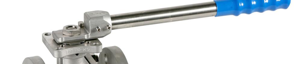

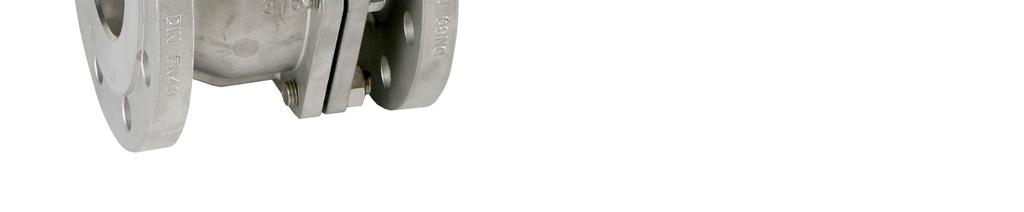


1 INSTALLATION, OPERATION AND MAINTENANCE MANUAL Full bore ball valve with flanged ends Ref. GENEBRE: 2526A 2528A
2 Installation, operation and maintenance instructions 1. Products description Transport and Storage conditions Valve Breakdown Installation Instructions 4.1 Preparation Installation Operating Instructions Usage Manual Operation Remote Operation Maintenance Instructions 6.1 Stem Leaks Body/edges joints leak Line Leaks (through seats) Repair Instructions 7.1 Disassembling Reassembling Torques Table Hygiene and Safety Instructions
3 1. Product description. Genebre, S.A. offers a wide range of ball valves (90º turn), designed and assembled to handle and drive fluids in industrial procedures. The compatibility of materials used to build the valves (see technical specifications) and the application of valves to the different industrial processes is at user's risk. Valves will have an optimal behaviour when working conditions do not exceed pressure and temperature limits (pressure curve) for which they have been designed. 2. Transport and Storage conditions Transport and storage of this type of products must be done in their original package VISUAL INSPECTION Check whether during transport, unloading and placement products have suffered any damage. Manual valves are provided by default in an open position whereas automated valves are usually offered in a closed position due to the standard error position NC (normally closed). During storage it is recommended to keep them in this same position, with the included protective wrapping to avoid damages or dirt accumulation in the ball. The wrap must not be removed until valve is to be installed. When possible, valves must be stored in a dry and clean environment. If you notice any kind of anomaly during reception of the goods, contact immediately with GENEBRE in order to determine the possible responsibilities on the issue. 3
4 IMPORTANT NOTE: Before installing and/or manipulating these elements READ CAREFULLY the enclosed instructions for use and OBSERVE all contained information. If any of the contents is not clear enough, please contact GENEBRE, S.A. User is responsible for the safe use of these products, as established in present instructions for use and in the specific technical documentation of the supplied device. 3. Valve breakdown 4
5 Nº Denominación/Name Material 1 Cuerpo / Body DIN ( CF8M) / WCB 2 Tapa / Cap DIN ( CF8M) / WCB 3 Bola / Ball Acero Inox AISI 316 / SS Eje / Stem Acero Inox AISI 316 / SS Asiento / Seat ball Teflón+15% FV / PTFE+15% GF. 6 Junta / Gasket Espirometálica / SS+Graphite 7 Arandela de Fricción / Friction Washer Teflón+grafito / PTFE+graphite 8 Tórica / O ring Viton 9 A. Prensa / Stem packing Teflón / PTFE 10 Anillo Prensa / Stem Ring Acero Inox AISI 316 / SS Arandela / Spring Washer Acero Inox AISI 301 / SS Tuerca / Nut Acero Inox AISI 316 / SS Arandela / Washer Acero Inox AISI 304 / SS Tope / Stopper Acero Inox AISI 304 / SS Maneta / Handle Acero Inox AISI 304 / SS Funda / Handle Sleeve Vynil 17 Tuerca / Nut Acero Inox AISI 316 / SS Perno / Stud Bolt Acero Inox AISI 316 / SS Antigiro / Lock Washer Acero Inox AISI 304 / SS Dispositivo Antiestático / Antiestatic Device Acero Inox AISI 304 / SS 304 Only in sizes from 2 ½ to 8 Nº Denominación/Name Material 14 Cuerpo maneta / Body Handle AISI Tuerca / Nut Acero Inox AISI Perno tope / Stopper Acero Inox AISI Antigiro / Lock Washer Acero Inox AISI Installation instructions 4.1) Preparation Remove any material remains of the valve wrapping. Serious problems may arise with the installation of a valve in a dirty pipe. 5
6 Make sure the pipe is not dirty and doesn t have welding particles, for example, before installing it. This may cause irreparable damages in the valve when the equipment is started prepare a clean working area. Plan beforehand enough space for future maintenance operations. Check correct performance of the valve by turning the handle clockwise and making sure the ball closes the fluid flow. If this is not the case, check if there are foreign particles inside the valve and repeat the whole operation. 4.2) Assembling Do not disassemble the valves to install them. Make sure the pipe's and edges flanges of the valve are clean. Use the corresponding screws in all of the flanges drill holes. Place an adequate joint in each end and align it in the center of the flanges. Tighten screws evenly and cross-shaped to avoid deformations. To do so, you must not force in any case the pipe to center the valve; it should take its position smoothly. Last, verify that screws are tightened with the recommended torque for each type of screw. Make sure the flanges joints are well placed. After assembling, check the tightness and performance of the valve. IMPORTANT INFORMATION: Design of this type of ball bore valves allows us to install them in any position as they are bidirectional, so the direction of fluid flow does not matter. If possible, it is recommended to install the valve in horizontal position and the Stem (handle) upwards. Valves do not have to support pipe's efforts so it is advisable to anticipate a good alignment and parallelism of such pipe. Once installed, it is recommended to open and close it a couple of times to verify its good performance and to check if there is any obstruction in the ball that prevents it from closing. It is also recommended to use filters in the pipe to extend lifecycle of the valve. 6
7 5. Operational instructions 5.1) Usage The ball valves provide a leak proof lock when used adjusted to the pressure and temperature values for which they have been designed. Avoid by all means to leave the valves in partially open position if you are not aware of the pressure drop and flow rate in that position, as the service life of the seat can be reduced and/or it can be damaged due to the ball bore valve. Any fluid that can be solidified, crystallized or polymerized should not remain in the ball cavity as it is harmful for performance, service life of the valve and it can even render it unusable. Seats for the valve, joints, body, ball, Stem and ends have to be fully compatible with the fluid circulating through the valve. Otherwise, valve could be seriously damaged. Torques required to operate valves are listed on the table in section ) Manual operation When operating the valve you must avoid excessive lateral efforts with the handle. To close it, you must turn the handle 90 degrees clockwise. When the handle is inline with the pipe, valve is open. In case you need to remove the handle to automate the valve, the Stem (part. 4) has a mechanized linear mark at the front part that allows us to know its current position (opened or closed). 5.3) Remote operation When automation of ball valves is required, GENEBRE S.A. can provide a great variety of pneumatic actuators, electric actuators, electropneumatic and electronic positioners to cover a large range of operations. 6. Maintenance instructions Frequency, location and process of maintenance will be determined by the user by taking into account usage of the product. However, periodical checks explained below will be useful to extend the service life of the valve and reduce installation problems: 7
8 6.1) Stem leaks Remove the handle or actuator, the locking nut washer (part. 19) and tighten the nut (part. 12) of the STEM packing. If the leak persists, valve should be disassembled to replace the STEM washers (part.7,8,9). See reparation instructions. 6.2) Body joints/edges leaks Check if the union nuts between body and cover (part. 17) are tightened. If they were loose, adjust them up until the recommended torques (IMPORTANT: adjustment of such screws will have to be done at room temperature). If leak continues, it is probably due to some damage in the body's joint or the locking surface and it will be necessary to disassemble the valve to repair it. See reparation instructions. 6.3) Line leaks (through seats). Check if the valve is in a completely closed position. If this is the case, leak is due to a seat or locking surface being damaged and it will be necessary to disassemble the valve to repair it. See reparation instructions. 7. Reparation instructions Before disassembling the pipe's valve to repair or replace it, make sure that line has been closed and depressurized because a bad operational procedure could cause a serious accident to you or to the installation system 8
9 7.1) Disassembling You must remove the valve from its installation to repair it, making sure the pipe has been previously depressurized. Prepare a clean working area and adequate tools to perform mechanical tasks. a. - Place the valve in closed position to impede the ball from damaging seats when disassembling. Remember that the STEM has a line in the frontal part to indicate position of the valve: parallel to the pipe means open; perpendicular means closed. b. - Loosen and remove the nuts (part. 17) on the studs (part. 18) that bring together the two different parts of the valve. Be careful not to damage the edges surfaces. c. - Remove the cover (part. 2) and the seat (part. 5) and joint (part. 6) located inside the body. d. - Remove the ball (part. 3) from the body (part. 1). This operation has to be performed carefully, otherwise the ball could be marked against the body. e. - Then, remove the other seat (part. 5) located inside the body. It should be removed with care, to avoid scratching or damaging the mechanized surfaces over which it is hermetically sealed. f.-to disassemble the STEM (part. 4), remove the following elements: Handle nut (part. 12). Dividing washer (part, 13). Handle (part. 15). Stopper plate (part.14) Lock nut (part. 19). Nut (part. 12). Spring washers (part. 11). Stem Ring (part. 10) Push the STEM to the inside part of the body and remove it. Then, remove the tow (part. 9) located inside the body. Remove the o-ring (part. 8) from its location and also remove the friction washer (part. 7). g. - Once the valve is completely disassembled, you must verify the state of each one of the pieces that compose it and the ones to be reused will have to be completely cleaned and stored in a safe and clean environment. 9
10 All locking surfaces in the ball, seats, joints and sides have to be checked for corrosion, erosion, metallic inlays in the seats and marks. If they were damaged or in case of doubt, they will need to be replaced. h. - Cleaning of the valve's pieces must be done using an adequate degreasing agent. You must be careful with the locking surfaces, for example, of the ball, locking sides of the ends and joints, because if they were damaged this could cause a bad impact in the valve's performance. 7.2) Rebuilding (assembling of the valve) Before proceeding to reassemble the valve, make sure that reparation kit and/or pieces to be used are appropriate and original from the factory. When it is assembled again, cleaning is essential for a long life for the valve. a. - Place a new friction washer (part. 7) on the STEM (part. 4) and also the o-ring (part. 8) in its corresponding location on the STEM. Lubricate the STEM with a thin layer of grease or silicon (for example, Dow Corning 200) and insert it in the valve's body (part.1), in the internal cavity, by pushing a bit to fix it. b. - Place a new stuffing box (part. 9) in its location. In the upper cavity of the body (part.1), the stuffing box (part. 10) and the Belleville washers (part. 11 ) with external borders together (concave position). Place the nut (part. 12) and tighten it. Make the STEM turn a couple of times and readjust the nut observing the torque specified value (See Torque table). If necessary, fasten with a wrench the internal body of the STEM to tighten the nut properly without making the STEM turn. It is convenient to match one of the nut vertexes with one of the STEM vertexes to be able to place the lock nut (part.19) later on. Note that if the nut is too tight, the rod torque will increase and service life of its elements will be reduced. c. - Place the STEM in a closed valve position and insert the ball (part. 3) inside the body (part. 1) by matching the ball slot with STEM milling (part. 4). d. - New seats (part. 5) and body's joint (part.6) can be placed on both sides of the valve, body (part. 1) and cover (part. 2) taking into account that the flat side of the seat must be facing downwards. 10
11 e.- Place the cover (part. 2) over the body (part. 1) matching the external flanges holes; place the nuts (part. 17) on the studs (part. 18) to bring together the two different parts of the valve. f.- Then, tighten the nuts (part. 17) adjusting slowly and alternating diagonally and evenly until obtaining the recommended tightening torque (see Torque table). 8.) Torque table: 8.1) Torques to activate the valves: MEASURE Activating torque Nm 1/2" 4 5 3/4" ¼ ½ ½ ) Tightening torque for the STEM nut: Following numerical data is provided as reference only. Specified torques are the ones used to activate the assembled STEM before ball and seats are assembled. Valve size Maximum torque (N.m.) 1/2" - 3/4" ¼ - 1 ½ ½ ,
12 8.3) Tightening torque Screws/ Nuts for joining the valve's different parts: It is required for all body screws to make contact of body metal against cover metal. Screw / Nut Maximum torque (N.m.) M12 88 M M (These values are the recommended values by screws manufacturers, in our case we have considered using them in cal. 8.8) 9. Hygiene and Safety Instructions: 9.1) Fluids that go through a valve can be corrosive, toxic, flammable or pollutant.when operating valves, you must follow the security instructions and it is recommended to use personal protection gadgets: 1) Protect your eyes. 2) Wear gloves and appropriate working clothes. 3) Wear safety footwear. 4) Wear a helmet. 5) Have running water at hand. 6) To operate flammable fluids, make sure you have an extinguisher at hand. Before removing a valve from a pipe, always check if the line is completely drained and depressurized. 9.2) Always operate the valve in open position to make sure there is no pressure in the internal cavity. 9.3) Any valve being used by toxic services department needs to obtain a cleanliness certificate before being operated. 12
F8/FB8 Series Ball Valves IOM-F8/FB8
 !!!CAUTION! Safety Precautions!!! Before removing valve from pipeline NOTE that: Media flowing through a valve may be corrosive, toxic, flammable, or a contaminant of harmful nature. Where there is evidence
IOM-CleanFLOW TM. CleanFLOW Series Ball Valves. SV F Flow Controls I N C O R P O R A T E D
 !!!CAUTION! Safety Precautions!!! Before removing valve from pipeline NOTE that: Media flowing through a valve may be corrosive, toxic, flammable, a contaminant or harmful nature. Where there is evidence
INSTALLATION & MAINTENANCE MANUAL
 INSTALLATION & MAINTENANCE MANUAL 3-WAY/4-WAY/5-WAY MULTI-PORT BALL VALVES T TEFLON PARTS - 1. Seat x 5 pcs. 2. Joint Gasket x 5 pcs. 3. Retainer Seal x 5 pcs. 4. Thrust Washer x 1 pc. 5. O-Ring x 1 pc
TBV OPERATION AND MAINTENANCE MANUAL SERIES 1800: FLANGED BALL VALVE. For technical questions, please contact the following:
 TBV OPERATION AND MAINTENANCE MANUAL SERIES 1800: FLANGED BALL VALVE For technical questions, please contact the following: Engineering Department 1537 Grafton Road Millbury, MA 01527 Phone: (508) 887-9400
INSTALLATION, OPERATION & MAINTENANCE INSTRUCTIONS
 TC-3000T/B/S & TC-3000TC & TC-000 (FS)/00 (FS) THREE PIECE BALL VALVE, 000 WOG & 00/000 WOG TCI ball valves have been designed and engineered to provide you with long lasting trouble free service when
2.- HANDLING OF VALVES BEFORE ASSEMBLY 3.- FITTING THE VALVE TO THE REST OF THE ASSEMBLY 5.- PERIODICAL INSPECTION OF THE VALVE AND MAINTENANCE
 Page 1 of 16 CONTENTS 1.- INTRODUCTION 2.- HANDLING OF VALVES BEFORE ASSEMBLY 3.- FITTING THE VALVE TO THE REST OF THE ASSEMBLY 4.- OPERATION OF A BALL VALVE 5.- PERIODICAL INSPECTION OF THE VALVE AND
When installing the screwed end, socket weld & flanged end valves the following respective procedures shall be followed for better performance.
 1. Storage LARSEN & TOUBRO LIMITED Page 1 of 5 1.1. All valves are to be stored in fully open position, in order to protect the sphere surface and soft valve seats. 1.2. Before shipping, the inlet and
OPERATION AND MAINTENANCE INSTRUCTIONS
 OPERATION AND MAINTENANCE INSTRUCTIONS 334 SERIES THREE-PIECE BALL VALVES 1/4 to 2-1/2 Installation and Operation Always install your valve according to accepted industry standards and practices and operate
FIGURE 310AM, 310AMSW & 311AM 3-PIECE BALL VALVE
 INTRODUCTION This instruction manual includes installation, operation and maintenance information for the figure 310AM, 310AMSW, and 311AM 3-piece 1000CWP, threaded end (NPT) or socket weld end (SW) ball
GT-200 GATE VALVES PN16, Screwed end
 Document No. : MD-QO-04-281 Date : 2009/07 /17 Version : 1.0 GT-200 GATE VALVES PN16, Screwed end USER MANUAL Modentic Industrial Corporation 14F-1,No.57Taya Rd.,Taichung,Taiwan,R.O.C. Email:modentic@ms9.hinet.net
Installation, Operation and Maintenance Guide II NIBCO High Performance Butterfly Valves Series 6822 and 7822
 Installation, Operation and Maintenance Guide II NIBCO High Performance Butterfly Valves Series 6822 and 7822 Statements: NIBCO High Performance Butterfly Valves, Series 6822 and 7822, have been designed
FIGURE 310A & 311A 3-PIECE BALL VALVE
 INTRODUCTION This instruction manual includes installation, operation and maintenance information for the figure 310A, 310ASW, 311A, and 311ASW 3-piece 1000CWP, threaded end (NPT) or socket weld end (SW)
IOM Manual. IOM Manual. Series 76/77.
 IOM Manual IOM Manual Series 76/77 www.flowlinevalves.com Flow Line Valve and Controls, L.L.C. 110 Main Project Road Schriever, LA 70395 P.O. Box 677 Schriever, LA 70395 Phone 985-414-6004 * Toll Free
COMMERCIAL. BV & BVM Series Installation Instructions 06/29/15
 COMMERCIAL Bray Controls Commercial Division 13788 West Road, Suite 00A Houston, Texas 77041 BCDSales@Bray.com Phone: 1-888-41-79 Fax: 1-888-41-70 www.braycommercialdivision.com BV & BVM Series Installation
INSTALLATION, OPERATING AND MAINTENANCE INSTRUCTIONS D SERIES TABLE OF CONTENTS
 INSTALLATION, OPERATING AND MAINTENANCE INSTRUCTIONS D SERIES GENERAL INFORMATION TERMS CONCERNING SAFETY UNPACKING INSTALLATIONS VALVE MAINTENANCE TABLE OF CONTENTS VALVE DISASSEMBLY AND REASSEMBLY PLUG
Flow Line Controls. Installation & Operations Manual SERIES 20/21 Pneumatic Actuators
 Flow Line Controls Installation & Operations Manual SERIES 20/21 Pneumatic Actuators Flow Line Controls, Inc. P.O. Box 677 Schriever, LA 70395 Phone: 985-414-6003 Toll Free 1-800-815-9226 Fax 985-414-6072
!!!CAUTION! Safety Precautions!!
 !!!CAUTION! Safety Precautions!! Before beginning installation or maintenance be sure to read and understand this entire manual. Always use protective gear. MAINTENANCE GENERAL SVF CleanFLOW ball valves
JT SERIES ANGLE STEM TANK BOTTOM BALL VALVE DN25 DN150. Installation, Maintenance and Operating Instructions
 JT SERIES ANGLE STEM TANK BOTTOM BALL VALVE DN25 DN150 Installation, Maintenance and Operating Instructions IMO-235 EN 3/2019 2 IMO-235 EN TABLE OF CONTENTS 1. GENERAL... 3 1.1 Scope of the Manual... 3
3-Way Ball Valve Type 23H
 Serial No. H-V062-E-4 contents 3-Way Ball Valve Type 23H User s Manual (1) Be sure to read following warranty clauses of our product 1 (2) General operating instructions 2 (3) General instruction for transportation,
IOM Manual. IOM Manual. Series 20/21.
 IOM Manual IOM Manual Series 20/21 www.flowlinevalves.com Flow Line Valve and Controls, L.L.C. 110 Main Project Road Schriever, LA 70395 P.O. Box 677 Schriever, LA 70395 Phone 985-414-6004 * Toll Free
Fig.01 Fig.02 Fig.03. Disassembly & Reassembly Instructions SBV-HP - Page 3
 M12A14 WITH FLOATING BACKSEAT 3 Fig.01 Fig.02 Fig.03 Disassembly & Reassembly Instructions SBV-HP - Page 3 M12A14 WITH FLOATING BACKSEAT 3 1. Caution, before any attempt is made to disassemble, verify
Ver Trunnion Ball Valve INSTALLATION, OPERATION AND MAINTENANCE MANUAL FBV/IOM/BA02
 Ver. 2008 Trunnion Ball Valve INSTALLATION, OPERATION AND MAINTENANCE MANUAL FBV/IOM/BA02 TABLE OF CONTENTS 1 APPLICATIONS...2 1.1 Applications...2 1.2 Performance Specifications...2 2 APPLICABLE STANDARDS...2
26 Series Stainless Steel 2-way Ball Valves
 1-800-899-0553 26 Series Stainless Steel 2-way Ball Valves Users Manual Installation, Operation, & Maintenance 1. General Precaution 1.1. Material Section Material deterioration is determined by the contained
N31 & N32 Series Installation, Operating & Maintenance
 N31 & N32 Series Installation, Operating & Maintenance Flanged Control Ball Valves Series N31 Class 150 Series N32 Class 300 Series included: N31P, N31X, AFN31P, N32P, N32X, AFN32P Sizes included: ½ -
Installation, Operation and Maintenance Instructions Series 608 Ball Valve
 b. With valve open, remove three body bolts, loosen fourth and swing out body. Remove fourth bolt and spread pipe ends Close valve, remove ball, seats, body seals. Return body to its original position
Series Single seated top guided control valve. Preventive maintenance. Overhauling procedure. Wörth am Main SERVICE NOTE. Control Valve Division
 Series 2000 Single seated top guided control valve Subject to change without notice Fig. 1: Series 2000 valve assembly Preventive maintenance Preventive maintenance consists of making a periodic visual
PFA LINED BALL VALVES Installation, Operation and Maintenance Manual
 ACRIS PFA LINED BALL VALVES WWW.AMRESIST.COM Table of Contents Safety Instructions - Definition of Terms............................................2 Introduction..............................................................2
USER INSTRUCTIONS. NAF Trunnball DL Ball Valves. Installation Operation Maintenance. Experience In Motion FCD NFENIM A4 01/15
 USER INSTRUCTIONS NAF Trunnball DL Ball Valves FCD NFENIM4168-01-A4 01/15 Installation Operation Maintenance Experience In Motion Contents SAFETY 3 1 General 3 2 Lifting 4 3 Receiving Inspection 4 4 Installation
contents (1) Be sure to read following warranty clauses of our product 1 (2) General operating instructions 2 User s Manual
 Be sure to read following warranty clauses of our product 1 (2) General operating instructions 2 User s Manual") Serial No. H-V003-E-12 contents 3-Way Ball Valve Type 23 User s Manual (1) Be sure to read following warranty clauses of our product 1 (2) General operating instructions 2 (3) General instruction for transportation,
Serial No. H-V003-E-12 contents 3-Way Ball Valve Type 23 User s Manual (1) Be sure to read following warranty clauses of our product 1 (2) General operating instructions 2 (3) General instruction for transportation,
PAHT / PAHT G pumps PAHT / PAHT G Disassembling and assembling
 Service guide PAHT / PAHT G pumps PAHT 256-308 / PAHT G 256-308 Disassembling and assembling hpp.danfoss.com Table of Contents 1. Introduction... 2 2. Disassembling the pump... 3 3. Assembling the pump...
Scope. Applicability. Caution. I & M CV3000 Series. Storage. Installation & Maintenance Instructions for Marwin CV3000 Series Three Piece Ball Valves
 I & M CV3000 Series 3170 Wasson Road Cincinnati, OH 45209 USA Phone 513-533-5600 Fax 513-871-0105 marwin@richardsind.com www.marwinvalve.com Installation & Maintenance Instructions for Marwin CV3000 Series
MERIDIAN, 2 or 3 PIECE, TRUNNION MOUNTED BALL VALVES
 INSTALLATION, OPERATION AND MAINTENANCE INSTRUCTIONS MERIDIAN, 2 or 3 PIECE, TRUNNION MOUNTED BALL VALVES Size Range 2 48 ASME Classes 150-2500 *It is recommended that the valve installer is familiar with
HIGH PRESSURE CONTROL VALVE PISTON BALANCED
 PISTON BALANCED All Rights Reserved. All contents of this publication including illustrations are believed to be reliable. And while efforts have been made to ensure their accuracy, they are not to be
CONTROL VALVES. Installation, Maintenance & Operating Instructions. Read these instructions carefully before installation or servicing.
 KOSO HAMMEL DAHL CONTROL VALVES KOSO HAMMEL DAHL 253 Pleasant Street West Bridgewater, MA 02379 tel: 774.517.5300 fax: 774.517.5230 www.hammeldahl.com Installation, Maintenance & Operating Instructions
Mars Series 88 Stainless Steel Reduced Bore Or Full Bore Ball Valve, Lever Operated, BSP Or Socket Weld Ends
 SPECIFICATION See our full range online at: www.vip-ltd.co.uk Mars Series 88 Stainless Steel Reduced Bore Or Full Bore Ball Valve, Lever Operated, BSP Or Socket Weld Ends VIP Product Codes 04/0466 (BSP)
CompoSeal butterfly valves, wafer style Installation & Maintenance Instructions
 Please read these instructions carefully This symbol indicates important messages and safety instructions. Intended valve use The valve is intended to be used only in applications within the pressure/temperature
FRP Ball Valves INSTALLATION & MAINTENANCE MANUAL
 FRP Ball Valves INSTALLATION & MAINTENANCE MANUAL FRP BALL VALVES TABLE OF CONTENTS MAINTENANCE AND INSTALLATION INSTRUCTIONS 1. 2. 2.1 2.2 2.3 2.4 GENERAL...Page 1 HANDLING...1 Receiving and Storing...1
DN15 DN250 PN 16. Corrosion Protection
 PRODUCTION STANDARTS DN15 DN250 PN 16 Design DIN 3357 Connection EN 1092-2 / ISO 7005-2 Face to Face DN15-DN150: EN558 Series 14 / DIN 3202 F4 DN200-DN250: EN558 Series 27 / DIN 3202 F5 Marking EN 19 Tests
YOUR GLOBAL FLOW CONTROL PARTNER. BRAY/MCCANNALOK EN High Performance Butterfly Valve Operation and Maintenance Manual
 YOUR GLOBAL FLOW CONTROL PARTNER BRAY/MCCANNALOK EN High Performance Butterfly Valve TABLE OF CONTENTS 1.0 Definition of Terms....................................... 2 2.0 Introduction...........................................
Installation, Operation, and Maintenance Manual
 Industrial Process Installation, Operation, and Maintenance Manual Series PBFV Plastic Lined Butterfly Valve - Lug and Wafer Style Table of Contents Table of Contents Introduction and Safety...2 Safety
5000/6000 SERIES BALL VALVES INSTALLATION - MAINTENANCE MANUAL
 Date: August 2011 / Page 1 of 6 5000/6000 SERIES BALL VALVES INSTALLATION - MAINTENANCE MANUAL DESIGN The design features three piece construction and a free floating ball allowing ease of maintenance
INSTALLATION, OPERATION AND MAINTENANCE MANUAL FOR INSTRUMENT ISOLATION VALVE
 PAGE : 01 OF 07 INSTALLATION, OPERATION AND MAINTENANCE MANUAL FOR INSTRUMENT ISOLATION VALVE PREPARED BY CHECKED BY APPROVED BY NAME M.Bhuvaneswari Y.Nesabalan M.Selvam DATE 22-Mar-201 19-Nov-2013 22-Nov-2013
Operating & Maintenance Manual For Steam Conditioning Valve
 For Steam Conditioning Valve 1 Table of Contents 1.0 Introduction 3 2.0 Product description 3 3.0 Safety Instruction 4 4.0 Installation and Commissioning 5 5.0 Valve Disassembly 6 6.0 Maintenance 6 7.0
Installation, Operation, and Maintenance Manual
 Industrial Process Installation, Operation, and Maintenance Manual Cam-Tite Ball Valve Table of Contents Table of Contents Introduction and Safety...2 Safety message levels...2 User health and safety...2
[DRAFT VERSION] For use for company in Europe who will place the product on the market. Please amend which necessary. Document No:
![[DRAFT VERSION] For use for company in Europe who will place the product on the market. Please amend which necessary. Document No:](/thumbs/87/96489423.jpg "[DRAFT VERSION] For use for company in Europe who will place the product on the market. Please amend which necessary. Document No:") Three-Piece ball valve EA-307 Series PED Category I, II EA-307 User Manual English Version [DRAFT VERSION] For use for company in Europe who will place the product on the market. Please amend which necessary.
Three-Piece ball valve EA-307 Series PED Category I, II EA-307 User Manual English Version [DRAFT VERSION] For use for company in Europe who will place the product on the market. Please amend which necessary.
Fisher 657 Diaphragm Actuator Sizes and 87
 Instruction Manual 657 Actuator (30-70 and 87) Fisher 657 Diaphragm Actuator Sizes 30 70 and 87 Contents Introduction... 1 Scope of Manual... 1 Description... 2 Specifications... 2 Installation... 3 Mounting
DL/DS Series Diaphragm Valve
 DL/DS Series Diaphragm Valve Service Instructions DL Series (Lever Handle) Valve DS Series (Round Handle) Valve Valves are shown with tube butt weld ends. These instructions also apply to DL or DS series
Fluid-O-Tech ROTOFLOW ROTARY VANE PUMP REBUILD MANUAL
 Fluid-O-Tech PUMP TECHNOLOGY AT ITS BEST WWW.FLUID-O-TECH.COM Office: 161 Atwater St., Plantsville, CT 06479 Phone: (860) 276-9270 Fax: (860) 620-0193 ROTOFLOW ROTARY VANE PUMP REBUILD MANUAL 08/09 Ed.,
Maintenance Instructions
 General Note These instructions contain information common to more than one model of Bevel Gear Drive. To simplify reading, similar models have been grouped as follows: GROUP 1 Models 11, 0, 1,, (illustrated),,
McCannalok HIGH PERFORMANCE BUTTERFLY VALVE OPERATION AND MAINTENANCE MANUAL. The High Performance Company
 McCannalok HIGH PERFORMANCE BUTTERFLY VALVE OPERATION AND MAINTENANCE MANUAL The High Performance Company Table of Contents Safety Information - Definition of Terms... 1 Introduction... 1 Installation...
NAF-Duball ball valves Maintenance and installation instructions List of spare parts
 NAF-Duball ball valves Maintenance and installation instructions List of spare parts Fi 41.61(4)GB 08.01 Contents SAFETY General 1 Lifting 2 Receiving inspection 3 Installation 4 Flange gaskets 5 Starting
J Flow Controls Model Numbering
 4665 Interstate Dr Cincinnati, OH 45246 Phone 513-731-2900 Fax 513-731-6939 3500 Series Valve Instruction and Maintenance Manual Caution: Prior to performing any repairs or maintenance on the valve assembly,
Ball Valve Type 21 21α Nominal size mm (1/2-4 )
") Serial No. H-V027-E-15 Contents Ball Valve Type 21 21α Nominal size 15-100mm (1/2-4 ) (1) Be sure to read the following warranty clauses of our product 1 (2) General operating instructions 2 (3) General
Serial No. H-V027-E-15 Contents Ball Valve Type 21 21α Nominal size 15-100mm (1/2-4 ) (1) Be sure to read the following warranty clauses of our product 1 (2) General operating instructions 2 (3) General
INSTALLATION - MAINTENANCE MANUAL Severe Service Series M4 Ball Valve
 INSTALLATION - MAINTENANCE MANUAL Severe Service Series M4 Ball Valve Date: May 2016/ Page 2 of 12 Table of Contents 1. Safety Information - Definition of Terms..........................2 2. Bill of Materials....................................
I-795/906. Series 795 and 906 Installation-Ready Knife Gate Valves WARNING INSTALLATION AND MAINTENANCE INSTRUCTIONS
 INSTALLATION AND MAINTENANCE INSTRUCTIONS I-795/906 Series 795 and 906 Installation-Ready Knife Gate Valves HANDWHEEL OPERATOR PNEUMATIC OPERATOR HYDRAULIC OPERATOR WARNING Read and understand all instructions
INSTALLATION & MAINTENANCE MANUAL SERIES 90SV/93V SEGMENTED V FLOW VALVES
 BRIEF INTRODUCTION The Segmented V Flow valve is an advanced quarter-turn control valve which can be used switch on and off and proportionally adjusted. The ball core is designed with a special V type
USER INSTRUCTIONS. Installation Operation Maintenance. NAF Setball SF Ball Sector Valves. Experience In Motion FCD NFENIM A4 09/16
 USER INSTRUCTIONS NAF Setball SF Ball Sector Valves FCD NFENIM4156-00 A4 09/16 Installation Operation Maintenance Experience In Motion Contents SAFETY 3 1 General 3 2 Lifting 4 3 Receiving Inspection 4
BALL VALVE WITH ADA PNEUMATIC ACTUATOR
 702-703 BALL VALVE WITH ADA PNEUMATIC ACTUATOR DESCRIPTION The 702-703 ball valves are dedicated to the automatic shut off of industrial fluid s lines. It is a 3 pieces full valve with internal screws
Val-Matic QuadroSphere Trunnion Mounted Ball Valve
 Manual No. QS-OM1-1 Val-Matic QuadroSphere Trunnion Mounted Ball Valve Operation, Maintenance and Installation Manual INTRODUCTION... 2 RECEIVING AND STORAGE... 2 INSTALLATION... 2 DESCRIPTION OF OPERATION...
Industrial Turbo Meters, Sizes 2" through 6"
 Industrial Turbo Meters Sizes 2" through 6" TUR-UM-00530-EN-19 (October 2014) User Manual Industrial Turbo Meters, Sizes 2" through 6" User Manual CONTENTS Scope of the Manual 5 Specifications 5 Product
I-317. AWWA Check Valves WARNING INSTALLATION AND MAINTENANCE INSTRUCTIONS SERIES 317 WARNING
 Read and understand all instructions before attempting to install, remove, adjust, or perform maintenance on any Victaulic piping products Wear safety glasses, hardhat, and foot protection. Failure to
Installation, Operation, and Maintenance Manual Full Port Y-Pattern, Bolted Bonnet, Globe and Check Valves
 SMITH VALVES Installation, Operation, and Maintenance Manual Full Port Y-Pattern, Bolted Bonnet, Globe and Check Valves Globe Valve Series: YG80/YG15 Welded Bonnet Globe Valve Series: YG87/YG17 Piston
OpTK. Product Instruction Manual. Spring Cylinder Rotary Actuators INTRODUCTION SAFETY INFORMATION INSTALLATION. Leading Technologies For Control
 Leading Technologies For Control Product Instruction Manual OpTK Spring Cylinder Rotary Actuators TABLE OF CONTENTS INTRODUCTION Safety Information... pg. 1 Unpacking... pg. 1 INSTALLATION... pg. 1 PREVENTIVE
Contents H-V034-E-12. Serial No. (page) (1) Be sure to read the following warranty clauses of our product 1. (2) General operating instructions 2
 (1) Be sure to read the following warranty clauses of our product 1. (2) General operating instructions 2") Serial No. H-V034-E-12 Sediment strainer (Type Y) Contents (page) (1) Be sure to read the following warranty clauses of our product 1 User s Manual (2) General operating instructions 2 (3) General instructions
Serial No. H-V034-E-12 Sediment strainer (Type Y) Contents (page) (1) Be sure to read the following warranty clauses of our product 1 User s Manual (2) General operating instructions 2 (3) General instructions
INSTALLATION, OPERATION & MAINTENANCE INSTRUCTIONS
 TC-0T/TC-0TM/TC-000/TC-0N/TC-0/TC-0M TWO PIECE BALL VALVE TCI ball valves have been designed and engineered to provide you with long lasting trouble free service when used in accordance with the instructions
INSTALLATION, OPERATION AND MAINTENANCE MANUAL OF KNIFE GATE DURGA VALVES PVT. LTD. ICHAPUR ROAD, CANAL SIDE, SANTRAGACHI, HOWRAH
 INSTALLATION, OPERATION AND MAINTENANCE MANUAL OF KNIFE GATE DURGA VALVES PVT. LTD. ICHAPUR ROAD, CANAL SIDE, SANTRAGACHI, HOWRAH-711104 INTRODUCTION - The knife gate is a uni-directional lug type valve
Installation, Operation, and Maintenance Manual
 Industrial Process Installation, Operation, and Maintenance Manual Series PBV Plastic Lined Ball Valve Table of Contents Table of Contents Introduction and Safety...2 Safety message levels...2 User health
Sediment strainer (Type Y)
") Installation,Operation and Maintenance Manual Serial No. H-V034-E-9 Sediment strainer (Type Y) Contents (1) Be sure to read the following warranty clauses of our product 1 User s Manual (2) General operating
Installation,Operation and Maintenance Manual Serial No. H-V034-E-9 Sediment strainer (Type Y) Contents (1) Be sure to read the following warranty clauses of our product 1 User s Manual (2) General operating
WARNING Carefully Read These Instructions Before Use
 DO NOT RETURN THIS SPRAYER TO STORE Call: 1-800-950-4458 Backpack Sprayer Use and Care Manual Manufactured for Northern Tool + Equipment Co., Inc. WARNING Carefully Read These Instructions Before Use Model
GRSM17 Pneumatic Center Punch Tool Owner s Manual and Operating Instructions
 Owner s Manual and Operating Instructions Table of Contents Page Information 2 Safety Guidelines and Warranty 3 Overview and Installation 4 Air System Requirements 5 Setting Controls 6 Installing Clamps
Metal Characterized-seated Control Valve 1. /4" 4" CPT 44 and 1 /2" 4" CPT 51/52 Installation, Operation and Maintenance Instructions
 17812-N Metal Characterized-seated Control Valve 1 /4 4 CPT 44 and 1 /2 4 CPT 51/52 Installation, Operation and Maintenance Instructions CAUTION: Flowserve recommends that all products which must be stored
Fisher TBX Hydro Plug Fixture
 Instruction Manual TBX Hydro-Plug Fixture Fisher TBX Hydro Plug Fixture Contents Introduction... 1 Scope of Manual... 1 Description... 2 Educational Services... 2 Principle of Operation... 2 Maintenance...
V-SEGMENT SERIES V-Port Segment Control Valves (VS/VV/VM) Installation & Maintenance Manual
 Installation & Maintenance Manual") CAUTION: 1. For your safety read this manual before installation or servicing. 2. Before installing or servicing, please ensure the line pressure has been relieved, and any hazardous fluids have been drained
CAUTION: 1. For your safety read this manual before installation or servicing. 2. Before installing or servicing, please ensure the line pressure has been relieved, and any hazardous fluids have been drained
Stem Assembly Supplement
 Installation, Operating & Maintenance Instructions Assembly Supplement Envirosafe Cryogenic & Low Temperature O-Ring as FM 00707 Cryogenic & Low Temperature Valves: This section contains only details of
Bray/ VAAS Slurry Series Knife Gate Valve 760/762/765/766/767/768 Series Operation and Maintenance Manual
 Bray/ VAAS Knife Gate Valve 760/762/765/766/767/768 Series Table of Contents Definition of Terms 1 Safety Instructions 1 Introduction 2 Unpacking 2 Storage 2 Installation 3 Commissioning 3 Cylinder-Operated
PNEUMATIC SLIDING VALVE
 INSTALLATION, OPERATION, & #: MM-SV001 6-23-09 Rev. A Page 1 of 8 PNEUMATIC SLIDING VALVE PART NUMBERS (Including, but not inclusive) SV704MSTS, SV714MSTS, SV754MSTS, SV764MSTS, SV774MSTS, SV706MSTS, SV716MSTS,
INSTALLATION, OPERATION & MAINTENANCE MANUAL Description Handling Installation Actuators...
 INSTALLATION, OPERATION & MAINTENANCE MANUAL INDEX Page 0 - Description 2 1 - Handling 2 2 - Installation 2 3 - Actuators 5 4 - Maintenance 5 41 - Gland packing replacement 6 42 - Seal replacement 6 43
NEECO INDUSTRIES INC. INSTRUCTION MANUAL 7 1/16 10K SLAB GATE BODY
 INSTRUCTION MANUAL 7 1/16 10K SLAB GATE BODY INTRODUCTION The NF-700 type gate valves provided by Neeco Industries are full-bore through conduit non-rising stem manually (w/ball screw) operated valves.
Model DF233 Control Valve
 Figure 1 DF233 Control Valve TABLE OF CONTENTS Introduction 2 Body and Packing Reassembly 7 Specifications 3 Fail Closed Actuator Reassembly 8 Valve Sizes 3 Fail Open Actuator Reassembly 9 Unpacking 4
Butterfly Valve Type 57P
 Butterfly Valve Type 57P Contents Lever Type: 50-200 mm (2-8 ) Body Material: CPVC Gear Type: 50-200mm (2-8 ) Body Material: CPVC (1) Be sure to read the following warranty clauses of our product 1 (2)
KEYSTONE SERIES 320 BUTTERFLY VALVES INSTALLATION AND MAINTENANCE INSTRUCTIONS
 Before installation these instructions must be fully read and understood HAZARD POTENTIALS disregarding of instructions improper use of product insufficiently qualified personnel Valve application to be
Diaphragm Valves Type 15
 Serial No. H-V031-E-8 Diaphragm Valves Type 15 User s Manual Contents (1) Be sure to read the following warranty clauses of our product 1 (2) General operating instructions 2 (3) General instructions for
Apollo Standard Port, Full Port & One Piece Flanged Ball Valves Installation, Operation, & Maintenance Guide
 I854000.F M16005 Apollo Standard Port, Full Port & One Piece Flanged Ball Valves Introduction This manual presents guidelines for the Installation, Operation and Maintenance of manual and automated Apollo
INSTALLATION, OPERATION AND MAINTENANCE INSTRUCTIONS
 INSTALLATION, OPERATION AND MAINTENANCE INSTRUCTIONS Contents Section 1. General Observations... 2 2. Operation... 4 3. Control During Operation... 5 4. Trouble Shooting... 6 5. Maintenance... 7 Please
Model DF269 Control Valve
 Figure 1 DF269 Control Valve TABLE OF CONTENTS Introduction 2 Fail Open Actuator Disassembly 6 General 2 Body and Packing Reassembly 7 Scope 2 Fail Closed Actuator Resassembly 8 Specifications 3 Fail Open
1/2" AIR DRIVEN DIAPHRAGM PUMP
 1/2" DRIVEN DIAPHRAGM PUMP OPERATION AND SERVICE GUIDE O-1225D NOV. 2008 Page 1 of 6 Refer to Bulletin P-605, Parts List P-9151 DRIVEN, DOUBLE DIAPHRAGM PUMP MANUAL Congratulations on purchasing one of
6701 KNIFE GATE VALVES
 INTRODUCTION This instruction manual includes installation, operation and maintenance information for 2" through 30" stainless steel and stainless steel lined knife gate valves. This manual addresses hand-wheel
WAYS BALL VALVES WITH ADA ACTUATOR
 783-786 3-WAYS BALL VALVES WITH ADA ACTUATOR MAIN CHARACTERISTICS The three-ways flanged ball valve type 783-785 à brides is dedicated to the mixing or deviating functions in process of fluids. With full
User s Manual CM2-ALV nd edition
 Control Valve Model: ALVB, ALVM ANSI Class 300 or under User s Manual CM2-ALV100-2001 2nd edition Copyright, Notices and Trademarks 2007-2012 Azbil Corporation All Rights Reserved. While this information
EC4 SERIES CRYOGENIC VALVES 1/4 2 Sizes
 12501 Telecom Drive, Tampa, FL 33637 Ph: (813) 978-1000 Fax: (813) 977-3329 www.cpc-cryolab.com INSTALLATION, OPERATING, AND MAINTENANCE INSTRUCTIONS 17/2.5.6 Rev. 0 EC4 SERIES CRYOGENIC VALVES 1/4 2 Sizes
Standard Valves Series Globe Valves Series Angle Valves Series Way-Valves
 Installation, Operation, Maintenance Instructions Standard Valves Series 035 000 Globe Valves Series 031 000 Angle Valves Series 033 000 3-Way-Valves 1 GENERAL INFORMATION These instructions are designed
Valtek Spring Cylinder Linear Actuators
 Valtek Linear Actuators GENERAL INFORMATION The following instructions are designed to assist in installing, troubleshooting and servicing Valtek spring cylinder actuators. Product users and maintenance
IMO-200EN 09/2010. Trunnion mounted forged ball valves Model FF and GG. Installation, Maintenance and Operating Instructions IMO-200EN 09/2010
 IMO-200EN 09/2010 Trunnion mounted forged ball valves Model FF and GG Installation, Maintenance and Operating Instructions IMO-200EN 09/2010 2 IMO-200EN Table of Contents I GENERAL INFORMATION...................
'C' Series Control Valves
 3060050/3 IM-F12-31 CH Issue 3 'C' Series Control Valves Installation and Maintenance Instructions 1. Safety information 2. General product information 3. Installation and Commissioning 4. Maintenance
Installation, Operation and Maintenance
 Plug Valve Specialists Strong Company Good Company Doc. No. 3ZQM-E-02 Approved by H.S.KIM Rev. No. C Checked by Y.J.KANG Issued 10,19,2015 Prepared by H.E.KO Non lubricated Lined Plug Valve Installation,
FLOWSERVE CORPORATION NOBLE ALLOY VALVE BALL VALVE REPAIR INSTRUCTION
 FLOWSERVE CORPORATION NOBLE ALLOY VALVE BALL VALVE REPAIR INSTRUCTION Cookeville Valve Operation 1978 Foreman Drive Cookeville, TN 38541 PH: 800-251-6761 931-432-4021 FAX: 931-432-5518 CONTENTS FLOWSERVE/NOBLE
Bray/McCannalok High Performance Butterfly Valve Operation and Maintenance Manual
 Bray/McCannalok High Performance Butterfly Valve Operation and Maintenance Manual Table of Contents Definition of Terms 1 Introduction 1 Installation 1 Maintenance 2 Stem Seal Replacement 4 Seat Replacement
REACTOR DISCHARGE VALVES S & DIGESTER BLOW VALVES SB & 5300SB B FLANGED BALL VALVES
 REACTOR DISCHARGE VALVES 8-12 530S & 5300 6-10 6300 DIGESTER BLOW VALVES 8-12 530SB & 5300SB 6-10 6300B FLANGED BALL VALVES Installation, Maintenance and Operating Instructions IMO-295 EN 11/2017 2 IMO-302
Valtek Auxiliary Handwheels and Limit Stops
 Valtek Auxiliary s and Limit Stops Table of Contents Page 1 General information 2 Installation 2 Side-mounted handwheels, size 25 and 50 (linear actuators) 3 Side-mounted handwheels, size 100 and 200 (linear
Installation,Operation and Maintenance Manual H-V016-E-10. Serial No. 目次 ( ページ ) 1. Be sure to read the following warranty clauses of our product 1
 1. Be sure to read the following warranty clauses of our product 1") Serial No. H-V016-E-10 Gauge Valve 目次 ( ページ ) 1. Be sure to read the following warranty clauses of our product 1 2. General operating instructions 2 User s Manual 3. General instructions for transportation,
Serial No. H-V016-E-10 Gauge Valve 目次 ( ページ ) 1. Be sure to read the following warranty clauses of our product 1 2. General operating instructions 2 User s Manual 3. General instructions for transportation,