B 2000 en. Explosion-protected gear units. Operating and Assembly Instructions
|
|
|
- Eustacia Chandler
- 6 years ago
- Views:
Transcription

1 B 2000 en Explosion-protected gear units Operating and Assembly Instructions
2 Explosion-protected gear units Operating and Assembly Instructions General safety and operating instructions 1. General Depending on its protection class, the device may have live, bare, moving or rotating parts or hot surfaces during operation,. Unauthorised removal of covers, improper use, incorrect installation or operation causes a risk of serious personal injury or material damage. All transport, installation, commissioning and maintenance work must be carried out by qualified specialist personnel (national accident prevention regulations must be observed). Within the meaning of this basic safety information, qualified specialist personnel are persons who are familiar with the installation, assembly, commissioning and operation of the product and who have the training and experience to recognise and avoid any hazards and risks. 2. Correct use NORD products may only be used according to the information in the catalogue and the associated technical documentation. Compliance with the operating and installation instructions is a prerequisite for fault-free operation and for the fulfilment of any warranty claims. These operating and installation instructions must be read before working with the device! These operating and installation instructions contain important information about servicing. They must therefore be kept close to the device. All details regarding technical data and permissible conditions at the installation site must be complied with. 3. Transport, storage Information regarding transport, storage and correct handling must be complied with. 4. Installation The device must be protected against impermissible loads. In particular, during transport and handling, components must not be deformed or changed. Touching of electronic components and contacts must be avoided. 5. Electrical Connection When working on live three-phase motors, the applicable national accident prevention regulations must be complied with (e.g. BGV A3, formerly VBG 4). The electrical installation must be implemented according to the applicable regulations (e.g. cable cross-section, fuses, earth lead connections). Information regarding EMC-compliant installation such as shielding, earthing and installation of cables can be found in the three-phase motor documentation. Compliance with the limiting values specified in the EMC regulations is the responsibility of the manufacturer of the system or machine. 6. Operation Appropriate safety measures must be taken for applications where failure of the device may result in injury. Where necessary, systems in which NORD devices are installed must be equipped with additional monitoring and protective equipment according to the applicable safety requirements, e.g. legislation concerning technical equipment, accident prevention regulations, etc. All covers and guards must be kept closed during operation. 7. Maintenance and repairs After the device has been disconnected from the power supply, live equipment components and power connections should not be touched immediately, because of possible charged capacitors. Further information can be found in this documentation. These safety instructions must be kept in a safe place! 2 B 2000 en-4217
3 Documentation Documentation Name: B 2000 Part No.: Series: Gear units and geared motors Type series: Gear unit Helical gear units types: NORDBLOC helical gear units Standard helical gear units Parallel shaft gear units Bevel gear units Helical worm gear units MINIBLOC worm gear units UNIVERSAL worm gear units Version list Title, Date B 2000, January 2013 B 2000, September 2014 B 2000, April 2015 B 2000, March 2016 B 2000, April 2017 B 2000, October 2017 Order number / / 3814 General corrections Comments / 1915 New gear unit types SK SK / / / 4217 General corrections Adaptation of new ATEX Directives as of 20/04/2016 General corrections New SK helical gear unit, SK 171.1, SK 371.1, SK 571.1, SK 771.1; General corrections New parallel shaft gear units SK ; SK ; SK ; SK New worm gear unit SK New declarations of conformity 2D + 2G; 3D + 3G Table 1: Version list B 2000 B 2000 en
4 Explosion-protected gear units Operating and Assembly Instructions Copyright notice As an integral component of the device described here, this document must be provided to all users in a suitable form. Any editing or amendment or other utilisation of the document is prohibited. Publisher Getriebebau NORD GmbH & Co. KG Getriebebau-Nord-Straße Bargteheide, Germany Fon +49 (0) / Fax +49 (0) / Member of the NORD DRIVESYSTEMS Group 4 B 2000 en-4217
5 Publisher B 2000 en
6 Explosion-protected gear units Operating and Assembly Instructions Table of Contents 1 Notes General information Safety and information symbols Explanation of designations used Correct use Safety information Other documents Disposal Description of gear units Type designation and type of gear unit Assembly instructions, storage, preparation, installation Transporting the gear unit Storage Long-term storage Inspecting the drive unit Checking the type plate data Checking the version Preparing for installation Installing the gear unit Fitting push-on gear units Fitting shrink discs Fitting the covers Fitting a standard motor Subsequent paintwork Fitting the cooling coil to the cooling system Temperature sticker Installation example for an SCX flange Installation of an oil expansion tank, Option OA Commissioning Check the oil level Activating the automatic lubricant dispenser Temperature measurement Operation with lubricant cooling Checking the gear unit Checklist Operation of the gear unit in explosive areas Service and maintenance Service and Maintenance Intervals Service and Maintenance Work Appendix Versions and maintenance Lubricants Torque values Troubleshooting Leakage and leak-tightness Declaration of Conformity Explosion protected gear units and geared motors, Category 2G and 2D Explosion protected gear units and geared motors, Category 3G and 3D Repair information Repairs Internet information Abbreviations B 2000 en-4217
7 Table of Contents B 2000 en
8 Explosion-protected gear units Operating and Assembly Instructions List of illustrations Figure 1:Type plate (example) Figure 2: Activation of the pressure vent Figure 3: Applying lubricant to the shaft and the hub Figure 4: Removing the factory-fitted closing cap Figure 5: Gear unit mounted to shaft with a shoulder using the fastening element Figure 6: Gear unit mounted to shaft without a shoulder using the fastening element Figure 7: Dismantling using dismantling device Figure 8: Mounting the rubber buffer (Option G and/or VG) on parallel shaft gear units Figure 9: Attaching the torque support on bevel gear and worm gear units Figure 10: Hollow shaft with shrink disc Figure 11: Fitting the covers, Option SH, Option H, and Option H Figure 12: Fitting the coupling onto the motor shaft - various types of coupling Figure 13: Cooling cover Figure 14: Position of the temperature sticker Figure 15: Installation example for an SCX flange Figure 16: Installing the expansion tank Figure 17: Checking the oil level with a dipstick Figure 18: Activating the automatic lubricant dispenser with standard motor mounting Figure 19: Adhesive label Figure 20: ATEX labelling Figure 21: Temperature sticker Figure 22: Measurement of gear rim wear on the ROTEX claw coupling Figure 23: Measurement of gear sleeve wear for gear BoWex couplings Figure 24: Replacing the automatic lubricant dispenser with standard motor mounting Figure 26: Measuring the oil level Figure 27: Oil level measurement SK SK Figure 28: Oil level SK Figure 29: Orientation for oil level check Figure 30: Parallel shaft gear units with oil level tank Figure 31: Declaration of Conformity for Category 2G / 2D Figure 32: Declaration of Conformity for Category 3G / 3D B 2000 en-4217
9 List of tables List of tables Table 1: Version list B Table 2: Disposal of materials Table 3: Helical gear units - Type designation and gear unit types Table 4: Large helical gear units - Type designation and gear unit types Table 5: NORDBLOC helical gear units - Type designation and gear unit types Table 6: NORDBLOC helical gear units - Type designation and gear unit types Table 7: Parallel shaft gear units - Type designation and gear unit types Table 8: Bevel gear units - Type designation and gear unit types Table 9: Helical worm gear units - Type designation and gear unit types Table 10: MINIBLOC - Type designation and gear unit types Table 11: UNIVERSAL worm gear units - Type designation and gear unit types Table 12: Limiting wear values for coupling gear rims Table 13: Oil fill quantities for standard helical gear units for ATEX category 3G and 3D Table 14: Lubricant table Table 15: Torque values Table 16: Overview of malfunctions Table 17: Definition of leaks according to DIN B 2000 en
10 Explosion-protected gear units Operating and Assembly Instructions 1 Notes 1.1 General information Read the Operating Manual carefully prior to performing any work on or putting the gear unit into operation. Strict compliance with the instructions in this Operating Manual is essential. This Operating Manual and all associated special documentation must be kept in the immediate vicinity of the gear unit. Getriebebau NORD accepts no liability for damage to persons, materials or assets as a result of the non-observance of this Operating Manual, operating errors or incorrect use. General wearing parts, e.g. radial seals are excluded from the warranty. If additional components are attached to or installed on or in the gear unit (e.g. motor, cooling system, pressure sensor etc.) or components (e.g. cooling system) are supplied with the order, the operating instructions for these components must be observed. If geared motors are used, compliance with the Motor Operating Manual is also necessary. If you do not understand the contents of this Operating Manual or additional operating instructions, please consult Getriebebau NORD! 10 B 2000 en-4217
11 1 Notes 1.2 Safety and information symbols Explanation of designations used DANGER! Indicates an immediate danger, which may result in death or serious injury. DANGER! Indicates an immediate danger, which may result in death or serious injury. Contains important information regarding explosion protection. WARNING CAUTION NOTICE Information Indicates a possibly dangerous situation, which may result in death or serious injury. Indicates a possibly dangerous situation, which may result in slight or minor injuries. Indicates a possibly harmful situation, which may cause damage to the product or the environment. Indicates hints for use and useful information. 1.3 Correct use These gear units generate a rotational movement and are intended for use in commercial systems. They satisfy the explosion protection requirements of Directive 2014/34/EU for the product category indicated on the type plate. No mixture from categories IID and IIG may be present during operation. The ATEX approval is void in case of a hybrid mixture. For geared motors, the declaration of conformity attached as an annex to these operating and installation instructions covers the attachment of the electric motor, but not the electric motor itself. The electric motor therefore always has a separate declaration of conformity. Commissioning (start of proper operation) is prohibited until it has been established that the machine complies with the local laws and directives. The EMC Directive 2004/108/EC and the Machinery Directive 2006/42/EC in their currently valid scope of application must be complied with in particular. WARNING Danger to persons Appropriate safety measures must be taken in the case of applications in which failure of a gear unit or geared motor may cause a hazard to persons. Safeguard a wide area around the hazard zone. B 2000 en
12 Explosion-protected gear units Operating and Assembly Instructions WARNING Explosion hazard Only components which comply with the applicable regulations of Directive 2014/34/EU may be fitted and operated. Observe the Declaration of Conformity and all safety information for the components. WARNING Material damage and personal injury If the gear unit is not used as designed, this may cause damage to the gear unit or the premature failure of components. Personal injury as a result of this cannot be ruled out. Strict compliance with the technical data on the type plate is essential. The documentation must be observed. 1.4 Safety information Observe all safety information, including that provided in the individual sections of this Operating Manual. All national and other regulations on safety and accident prevention must also be observed. DANGER! Explosion hazard Explosion hazard. Failure to comply may cause severe, or even fatal injuries. All work, e.g. transportation, storage, installation, electrical connection, commissioning, servicing and maintenance must be performed in a non-explosive atmosphere. DANGER! Severe personal injury Serious physical and property damage may result from inappropriate installation, non-designated use, incorrect operation, non-compliance with safety information, unauthorised removal of housing components or safety covers and structural modifications to the gear unit. All work, e.g. transportation, storage, installation, electrical connection, commissioning, servicing, maintenance and repair must only be performed by qualified specialist personnel. Observe the Operating Manual. Observe the safety information. Observe the safety and accident prevention regulations. Tighten the driven elements or secure the parallel key before switching on. Do not make any structural modifications. Do not remove any safety devices. If necessary, wear hearing protection when working in the immediate vicinity of the gear unit. All rotating components must be provided with guards. In standard cases, covers are fitted by NORD. The covers must always be used if contact protection is not provided by other methods. 12 B 2000 en-4217
13 1 Notes DANGER! Severe personal injury The surfaces of gear units or geared motors may become hot during or shortly after operation. Installation and maintenance work must only be performed when gear unit is at a standstill and has cooled down. The drive must be isolated and secured to prevent accidental start-up. Wear protective gloves. Shield hot surfaces with contact guards. Do not store inflammable objects or substances in the immediate vicinity of the gear unit. WARNING Serious personal injury and material damage Serious injury and material damage due to improper transport are possible. No additional loads may be attached. Transportation aids and lifting gear must have an adequate load-bearing capacity. Pipes and hoses must be protected from damage. CAUTION Cutting hazard Danger of cuts from exterior edges of attachment adapters, flanges and covers. Contact freezing with metallic components in case of low temperatures. In addition to personal protective equipment, wear suitable protective gloves and suitable goggles during assembly, commissioning, inspection and maintenance, in order to prevent injuries. It is recommended that repairs to NORD Products are carried out by the NORD Service department. B 2000 en
14 Explosion-protected gear units Operating and Assembly Instructions 1.5 Other documents Further information may be obtained from the following documents: Gear unit catalogues (G1000, G1012, G1014, G1035, G1050, G2000), Operating and maintenance instructions for the electric motor, if applicable, the Operating Manuals for attached or supplied options 1.6 Disposal Observe the current local regulations. In particular, lubricants must be collected and disposed of correctly. Gear unit components Gear wheels, shafts, rolling bearings, parallel keys, locking rings, Gear unit housing, housing components, Light alloy gear unit housing, light alloy gear unit housing components, Worm gears, bushes,... Radial seals, sealing caps, rubber components, Coupling components Flat seals Gear oil Synthetic gear oil (type plate code: CLP PG) Cooling spiral, embedding material of the cooling spiral, screw fittings Material Steel Grey cast iron Aluminium Bronze Elastomers with steel Plastic with steel Asbestos-free sealing material Additive mineral oil Polyglycol-based lubricants Copper, epoxy, yellow brass Table 2: Disposal of materials 14 B 2000 en-4217
15 2 Description of gear units 2 Description of gear units 2.1 Type designation and type of gear unit Gear unit types / Type designations Helical gear units SK 11E, SK 21E,... SK 51E (1-stage) SK 02, SK 12,... SK 52, SK 62N (2-stage) SK 03, SK 13, SK 23, SK 33N, SK 43, SK 53 (3-stage) Versions / Options - Foot-mounted version IEC Standard IEC motor mounting F Output flange B5 NEMA Standard NEMA motor attachment XZ Base and output flange B14 W Free input shaft XF Base and output flange B5 VI Viton radial seals VL Reinforced bearings OA Oil expansion tank AL Solid shaft, reinforced axial bearings SO1 Synthetic oil ISO VG 220 Table 3: Helical gear units - Type designation and gear unit types Gear unit types / Type designations Helical gear units SK 62, SK 72, SK 82, SK 92, SK 102 (2-stage) SK 63, SK 73, SK 83, SK 93, SK 103 (3-stage) Versions / Options - Foot-mounted version NEMA Standard NEMA motor attachment F Output flange B5 W Free input shaft XZ Base and output flange B14 VI Viton radial seals XF Base and output flange B5 OA Oil expansion tank VL Reinforced bearings SO1 Synthetic oil ISO VG 220 IEC Standard IEC motor mounting Table 4: Large helical gear units - Type designation and gear unit types B 2000 en
16 Explosion-protected gear units Operating and Assembly Instructions Gear unit types / Type designations NORDBLOC helical gear units SK 320, SK 172, SK 272,... SK 972 (2-stage) SK 273, SK 373,... SK 973 (3-stage) SK 071.1, SK 171.1, SK 371.1, SK 571.1, SK (single stage) SK 072.1, SK (2-stage) SK 372.1,. SK (2-stage) SK 373.1,. SK (3-stage) SK 772.1, SK 872.1, SK (2-stage) SK 773.1, SK 873.1, SK (3-stage) Versions / Options - Foot-mounted version NEMA Standard NEMA motor attachment F Output flange B5 W Free input shaft XZ Base and output flange B14 VI Viton radial seals XF Base and output flange B5 OA Oil expansion tank VL Reinforced bearings SO1 Synthetic oil ISO VG 220 IEC Standard IEC motor mounting Table 5: NORDBLOC helical gear units - Type designation and gear unit types Gear unit types / Type designations Standard helical gear units SK 0, SK 01, SK 20, SK 25, SK 30, SK 33 (2-stage) SK 000, SK 010, SK 200, SK 250, SK 300, SK 330 (3-stage) Versions / Options - Foot-mounted version AL Solid shaft, reinforced axial bearings Z Output flange B14 IEC Standard IEC motor mounting XZ Base and output flange B14 NEMA Standard NEMA motor attachment XF Base and output flange B5 W Free input shaft F Output flange B5 VI Viton radial seals 5 Reinforced output shaft SO1 Synthetic oil ISO VG 220 V Reinforced drive Table 6: NORDBLOC helical gear units - Type designation and gear unit types 16 B 2000 en-4217
17 2 Description of gear units Gear unit types / Type designations Parallel shaft gear units SK 0182NB, SK , SK 0282NB, SK , SK 1282, SK ,... SK 9282, SK 10282, SK (2-stage) SK , SK , SK 1382NB, SK , SK 2382,.. SK 9382, SK 10382, SK 11382, SK 12382, SK , SK (3-stage) Versions / Options A Hollow shaft version VL Reinforced bearings V Solid shaft version VLII Agitator version Z Output flange B14 VLIII Drywell agitator version F Output flange B5 SCX Screw Conveyor Flange X Foot mounting IEC Standard IEC motor mounting S Shrink disc NEMA Standard NEMA motor attachment VS Reinforced shrink disc W Free input shaft EA Hollow shaft with internal spline VI Viton radial seals G Rubber buffer OA Oil expansion tank VG Reinforced rubber buffer SO1 Synthetic oil ISO VG 220 B Fastening element CC Casing cover with cooling spiral H Covering cap as contact guard OT Oil level tank H66 Covering cap IP66 Table 7: Parallel shaft gear units - Type designation and gear unit types Double gear units consist of two single gear units. They are to be treated as per the instructions in this Manual, i.e. as two individual gear units. Type designation for double gear units: e. g. SK 73 /22 (consisting of single gear units SK 73 and SK 22). B 2000 en
18 Explosion-protected gear units Operating and Assembly Instructions Gear unit types / Type designations Bevel gear units SK 92072, SK 92172, SK 92372, SK 92672, SK 92772, SK , SK , SK , SK , SK , SK , SK , SK , SK , SK , SK , SK (2-stage) SK , SK , SK , SK , SK , SK , SK , SK , SK , SK , SK , SK (3-stage) SK , SK , SK , SK , SK ,SK (4-stage) Versions / Options - Foot-mounted version H Covering cap as contact guard A Hollow shaft version H66 Covering cap IP66 V Solid shaft version VL Reinforced bearings L Solid shaft both sides VLII Agitator version Z Output flange B14 VLIII Drywell agitator version F Output flange B5 SCX Screw Conveyor Flange X Foot mounting IEC Standard IEC motor mounting D Torque arm NEMA Standard NEMA motor attachment K Torque bracket W Free input shaft S Shrink disc VI Viton radial seals VS Reinforced shrink disc OA Oil expansion tank EA Hollow shaft with internal spline SO1 Synthetic oil ISO VG 220 R Back stop CC Casing cover with cooling spiral B Fastening element Table 8: Bevel gear units - Type designation and gear unit types 18 B 2000 en-4217
19 2 Description of gear units Gear unit types / Type designations Helical worm gear units SK 02040, SK , SK 02050, SK 12063, SK 12080, SK 32100, SK (2- stage) SK 13050, SK 13063, SK 13080, SK 33100, SK (3-stage) Versions / Options - Foot mounting with solid shaft B Fastening element A Hollow shaft version H Covering cap as contact guard V Solid shaft version H66 Covering cap IP66 L Solid shaft both sides VL Reinforced bearings X Foot mounting IEC Standard IEC motor mounting Z Output flange B14 NEMA Standard NEMA motor attachment F Output flange B5 W With free drive shaft D Torque support VI Viton radial seals S Shrink disc OA Oil expansion tank Table 9: Helical worm gear units - Type designation and gear unit types Gear unit types / Type designations MINIBLOC worm gear units SK 1S 32, SK 1S 40, SK 1S 50, SK 1S 63, SK 1SU..., SK 1SM 31, SK 1SM 40, SK 1SM 50, SK 1SM 63, (single stage) SK 2S32NB, SK 2S40NB, SK 2S50NB, SK 2S63NB, SK 2SU, SK 2SM40, SK 2SM50, SK 2SM63 (2-stage) Versions / Options - Foot mounting with solid shaft X Foot mounting A Hollow shaft version B Fastening element V Solid shaft version IEC Standard IEC motor mounting L Solid shaft both sides NEMA Standard NEMA motor attachment Z Output flange B14 W With free drive shaft F Output flange B5 VI Viton radial seals D Torque support Table 10: MINIBLOC - Type designation and gear unit types B 2000 en
20 Explosion-protected gear units Operating and Assembly Instructions Gear unit types / Type designations UNIVERSAL worm gear units SK 1SI31, SK 1SI40, SK 1SI50, SK 1SI63, SK 1SI75, SK 1SID31, SK 1SID40, SK 1SID50, SK 1SID63, SK 1SID75 SK 1SIS31,, SK 1SIS75, SK 1SD31, SK 1SD40, SK 1SD50, SK 1SD63, SK 1SIS-D31,, SK 1SIS-D63 SK 1SMI31, SK 1SMI40, SK 1SMI50, SK 1SMI63, SK 1SMI75 SK 1SMID31,, SK 1SMID63 (1-stage) SK 2SD40, SK 2SD50, SK 2SD63, SK 1SI /31, SK 1SI /H10, SK 2SID40,, SK 2SID63 SK 2SIS-D40,, SK 2SIS-D63 SK 2SMI40, SK 2SMI50, SK 2SMI63 SK 2SMID40, SK 2SMID50, SK 2SMID 63 (2-stage) Versions / Options V Solid shaft or plug-in shaft H10 Modular contrate pre-stage A Hollow shaft version /31 Worm pre-stage L Solid shaft both sides /40 Worm pre-stage X Feet on three sides IEC Standard IEC motor mounting Z Output flange B14 NEMA Standard NEMA motor attachment F Output flange B5 W With free drive shaft D Torque support VI Viton radial seals H Covering cap Table 11: UNIVERSAL worm gear units - Type designation and gear unit types 20 B 2000 en-4217
21 3 Assembly instructions, storage, preparation, installation 3 Assembly instructions, storage, preparation, installation Please observe all general safety instructions ((please see chapter 1.4 "Safety information")), the safety information in the individual sections and the proper use ((please see chapter 1.3 "Correct use")). 3.1 Transporting the gear unit WARNING Hazard due to heavy loads Severe injuries and material damage due to falling or tipping heavy loads are possible. Standing under the gear unit during transport is extremely dangerous. To prevent injury, the danger area must be generously cordoned off. Only transport using the eyebolts attached to the gear unit. No additional loads may be attached. If geared motors have an additional eyebolt attached to the motor, this must also be used. The thread of the eyebolt must be fully screwed in. Avoid pulling the eyebolts at an angle. NOTICE Gear unit damage Damage to the gear unit due to improper use is possible. Prevent damage to the gear unit. Impacts to the free ends of the shafts may cause internal damage to the gear unit. Use adequately dimensioned and suitable means of transportation. Lifting tackle must be designed for the weight of the gear unit. The weight of the gear unit can be obtained from the dispatch documents. B 2000 en
22 Explosion-protected gear units Operating and Assembly Instructions 3.2 Storage For short-term storage before commissioning, please observe the following: Store gear units in the fitting position ((please see chapter 6.1 "Versions and maintenance")) and secure them against falling, Lightly oil bare metal housing surfaces and shafts Store in a dry place, Temperature in the range from 5 C to + 50 C without large fluctuations, Relative humidity less than 60 %, No direct exposure to sunlight or UV light, No aggressive, corrosive substances (contaminated air, ozone, gases, solvents, acids, alkalis, salts, radioactivity etc.) in the immediate vicinity, No vibration or oscillation 3.3 Long-term storage CAUTION Injury to persons Incorrect or excessively long storage may result in malfunctions of the gear unit. Perform an inspection of the gear unit prior to commissioning if the permissible storage time has been exceeded. Information Long-term storage For storage or standstill periods in excess of 9 months, Getriebebau NORD recommends the long-term storage option. With the long-term storage option and the use of the measures listed below, storage for up to 2 years is possible. As the actual influences on the unit greatly depend on the local conditions, these times should only be regarded as guide values. 22 B 2000 en-4217
23 3 Assembly instructions, storage, preparation, installation Conditions of the gear unit and storage area for long-term storage prior to commissioning: Store in the fitting position (please see chapter 6.1 "Versions and maintenance") and secure them against falling. Transportation damage to the external paint must be repaired. Check that a suitable rust inhibitor is applied to the flange bearing surfaces. If necessary apply a suitable rust inhibitor to the surfaces. Gear units with the long-term storage option are completely filled with lubricant or have VCI corrosion protection agent mixed with the gear oil (see adhesive label on the gear unit, or are not filled with oil, but rather with small quantities of VCI concentrate. The sealing band in the vent plug must not be removed during storage. The gear unit must remain sealed tight. Store in a dry place. In tropical regions the gear unit must be protected against damage by insects. Temperature in the range from 5 C to + 40 C without large fluctuations. Relative humidity less than 60 %. No direct exposure to sunlight or UV light. No aggressive, corrosive substances (contaminated air, ozone, gases, solvents, acids, alkalis, salts, radioactivity etc.) in the immediate vicinity. No vibration or oscillation Measures during storage or standstill periods If the relative humidity is < 50 % the gear unit can be stored for up to 3 years. Measures before commissioning If the storage or standstill period exceeds 2 years or the temperature during short-term storage has greatly deviated from the standard range, the lubricant in the gear unit must be replaced before commissioning. If the gear unit is completely filled, the oil level must be reduced before commissioning. For gear units without oil filling, the oil level for the version must be filled before commissioning. The VCI concentrate may remain in the gear unit. Lubricant quantities and types must be filled according to the details on the type plate. B 2000 en

24 Explosion-protected gear units Operating and Assembly Instructions 3.4 Inspecting the drive unit DANGER Explosion hazard Explosion hazard. Failure to comply may cause severe, or even fatal injuries. All work, e.g. transportation, storage, installation, electrical connection, commissioning, servicing and maintenance must be performed in a non-explosive atmosphere. The drive unit must be inspected and may only be installed if: No damage, e.g. due to storage or transport is apparent. In particular the radial seals, the sealing caps and the covers must be inspected for damage. No leakage or no oil loss is visible. No corrosion or other indications of incorrect or damp storage is apparent. The packaging material has been completely removed. 3.5 Checking the type plate data DANGER! Explosion hazard Explosion hazard. Failure to comply may cause severe, or even fatal injuries. It must be checked and ensured that the gear unit type, all technical data and the ATEX labelling conform to the planning of the plant or the machine. The type plate must be firmly attached to the gear unit and must not be subjected to permanent soiling. Please contact the NORD service department if the type plate is illegible or damaged. Figure 1:Type plate (example) 24 B 2000 en-4217
25 3 Assembly instructions, storage, preparation, installation Explanation of the type plate Abbreviations Unit Designation See Section Type - NORD gear unit type No. - Serial number iges - Overall gear unit ratio n2 rpm Rated speed of gear unit output shaft* n1 rpm Rated speed of the gear unit drive shaft or the drive motor* IM - Configuration (installation orientation) 6.1 M2 Nm Max. permissible gear unit output shaft torque P1 kw Max. permissible drive power or motor power Bj - Year of manufacture: FR2 kn Max. permissible transverse force on the gear unit output shaft 3.9 FR1 kn Max. permissible transverse force on the gear unit drive shaft for option W 3.9 Tu C Permissible ambient temperature for the gear unit FA2 kn Max. permissible axial force on the gear unit output shaft 3.9 FA1 kn Max. permissible axial force on the gear unit drive shaft for option W 3.9 MI h Interval for general overhaul of the gear unit in operating hours or according to the specification of the dimensionless maintenance class CM 5.2 xr2 mm Max. dimension for the point of application of the transverse force FR2 3.9 Oil - Gear unit oil type (standard designation) 6.2 Last line - Labelling as per ATEX (DIN EN ): 1. Group (always II, not for mines) 2. Category (2G, 3G for gas or 2D, 3D for dust) 3. Ignition protection type if fitted (c) 4. Explosion group if applicable (IIC, IIB) 5. Temperature class (T1-T3 or T4 for gas) or max. surface temperature (e.g. 125 C for dust) or special max. surface temperature see special documentation (TX) 6. Temperature measurement on commissioning (X) 4.3 S - Number of the special documentation, consisting of serial no. / year * The maximum permissible speeds are 10% above the rated speed, if the maximum permissible drive power P1 is not exceeded. If the fields F R1, F R2, F A1 and F A2 are empty, the forces are zero. If the field x R2 is empty, the point of application of force F R2 is central on the driven shaft journal 3.9. B 2000 en
26 Explosion-protected gear units Operating and Assembly Instructions Please note that for geared motors (gear units with attached electric motors) the electric motor has its own type plate and separate ATEX designation. The motor labelling must also comply with data for the planning of the plant or the machine. The lowest explosion protection level on the gear unit and the motor labelling applies for the geared motor unit. If the electric motor is driven with a frequency inverter, the motor requires ATEX approval for inverter operation. If the motor is operated with an inverter, significant differences between the nominal speeds on the type plates of the motor and the gearbox are normal and permissible. For operation of the motor with the mains supply, differences of the nominal speeds on the motor and the gear unit of up to ± 60 rpm are permissible. 3.6 Checking the version DANGER Explosion hazard Explosion hazard. Failure to comply may cause severe or even fatal injuries. The gear unit may only be operated in the stated version. The permissible version is stated on the type plate (IM ). If an X is present in the field IM, the special documentation, whose number is in field S, must be observed. Section 6.1 "Versions and maintenance" or the special documentation, shows the configuration of the individual types of gear units. It must be checked and ensured that the configuration as stated on the type plate complies with the installation orientation and that the installation orientation does not change during operation. Gear units bearing the abbreviation UN in field IM of the type label are version independent. Please heed the Operating Instructions for the motor, in particular with regard to the chosen version. 26 B 2000 en-4217
27 3 Assembly instructions, storage, preparation, installation 3.7 Preparing for installation CAUTION Injury to persons Transport damage may cause malfunctions of the gear unit, which may cause material damage or personal injury. Please inspect the delivery for transport and packaging damage immediately on receipt. Report any damage to the carrier immediately. Gear units with transport damage must not be commissioned. The drive unit must be inspected and may only be installed if no transportation damage or leaks are visible. In particular the radial seals and the sealing caps must be inspected for damage. Pay attention to leaked lubricants, they may cause slips. All bare metal surfaces and shafts of the gear unit are protected against corrosion with oil, grease or corrosion protection agents before shipping. Thoroughly remove all oil, grease or corrosion protection agents and any dirt from the shafts and flange surfaces before assembly. DANGER! Explosion hazard Explosion hazard. Failure to comply may cause severe, or even fatal injuries. Care must be taken that drive elements attached to the gear unit, such as clutches, pulleys etc. and drive motors are also ATEX-compliant. In applications where an incorrect rotational direction may result in damage or potential risk, the correct rotational direction of the output shaft is to be established by test running the drive when uncoupled and guaranteeing such for subsequent operation. Gears with integrated return stops are marked with arrows on the drive/driven sides. The arrows point in the rotation direction of the gear unit. When connecting the motor and during motor control, it must be ensured that the gear unit can only operate in the direction of rotation. (For further explanations see catalogue G1000 and WN ) NOTICE Gear unit damage For gear units with an integrated back stop, switching the drive motor to the blocked direction of rotation, i.e. incorrect direction of rotation, may result in damage to the gear unit. Take care that the direction of rotation of the gear unit is correct when connecting the motor and the motor control unit. B 2000 en

 must be fitted in accordance with works standard WN 0-521 30. Screw the enclosed M12x1.5 pressure relief screw into the tank.")
28 Explosion-protected gear units Operating and Assembly Instructions Ensure that no aggressive or corrosive substances are present in the area surrounding the installation site or are subsequently expected during operation, which attack metal, lubricants or elastomers. In case of doubt, please contact Getriebebau NORD and take the recommended action. Oil expansion tanks (Option OA) must be fitted in accordance with works standard WN For M10 x 1 screw fittings, the enclosed factory standard WN must also be observed. Oil level tanks (Option OT) must be fitted in accordance with works standard WN Screw the enclosed M12x1.5 pressure relief screw into the tank. The pressure vent must be activated prior to commissioning. To activate, remove the transport securing devices. Double gear units consist of two single units and are equipped with 2 oil chambers and 2 pressure vents. Position of the vent plug (please see chapter 6.1 "Versions and maintenance"). Explanation 1 Vent screw 2 Transport securing device Figure 2: Activation of the pressure vent 3.8 Installing the gear unit DANGER! Explosion hazard Explosion hazard. Failure to comply may cause severe, or even fatal injuries. No explosive atmosphere must be present when installing the gear unit. The cooling air supplied to the gear unit/geared motor must be within the permissible temperature range stated on the type plate. In case of direct sunlight falling onto the gear unit, the cooling air supplied to the gear unit/geared motor must be at least 10 C below the highest permissible temperature of the ambient temperature range Tu, which is stated on the type plate. WARNING Danger of burns The surfaces of gear units or geared motors may become hot during or shortly after operation. Hot surfaces which can be touched directly must be protected with a contact guard. 28 B 2000 en-4217
29 3 Assembly instructions, storage, preparation, installation NOTICE Damage to the gear unit due to overheating The gear unit may be damaged by overheating. During installation:: Ensure a free flow of air to all sides of the gear unit. Ensure adequate space around the gear unit. With geared motors, the cooling air of the motor fan must be able to flow unobstructed onto the gear unit. Do not enclose or encase the gear unit/geared motor. Do not subject the gear unit to highly energetic radiation. Do not direct warm exhaust air from other units onto the gear unit/geared motor. The base or flange to which the gear unit is attached must not input any heat into the gear unit during operation. Do not allow dust to accumulate in the area of the gear unit The base or flange to which the gear unit is fitted should be vibration-free, torsionally rigid and flat (flatness error <0.2 mm). All contamination to the bolting surfaces of gear unit and base and/or flange must be thoroughly removed. The gear housing must always be earthed. With geared motors, earthing via the motor connection must be ensured. The gear unit must be precisely aligned with the drive shaft of the machine in order to prevent additional forces from being imposed on the gear unit due to distortion. Welding of the gear unit is prohibited. The gear unit must not be used as the earth connection for welding work, as this may cause damage to the bearings and gear wheels. The gear unit must be installed in the correct orientation (please see chapter 3.6 "Checking the version") and (please see chapter 6.1 "Versions and maintenance"). All gear unit feet and/or all flange bolts on each side must be used. Bolts must have a minimum quality of The bolts must be tightened to the correct torques (please see chapter 6.3 "Torque values"). Tension-free bolting must be ensured, particularly for gear units with a foot and flange. Oil checking and oil drain screws must be accessible. 3.9 Fitting push-on gear units NOTICE Gear unit damage The bearings, gear wheels, shafts and housing may be damaged by incorrect fitting. Observe the assembly instructions. The push-on gear unit must be fitted onto the shaft using a suitable puller, which will not exert damaging axial forces on the gear unit. In particular, do not hit the gear unit with a hammer. Assembly and subsequent dismantling is aided by applying an anti-corrosive lubricant to the shaft before fitting (e.g. NORD Anti-Corrosion Part No ). Excess grease or anti-corrosion agent may escape after assembly and may drip off. Clean these points on the driven shaft after a running-in time of approx. 24 hours. This escape of grease is not due to a leak in the gear unit. B 2000 en
30 Explosion-protected gear units Operating and Assembly Instructions Figure 3: Applying lubricant to the shaft and the hub Information Fastening element The gear unit can be fitted to shafts with and without a shoulder using the fastening element (Option B). Tighten the bolt of the fastening element to the correct torque (please see chapter 6.3 "Torque values"). For gear units with option H66, the factory-fitted closing cap must be removed before assembly. For push-on gear units with option H66 and fastening element (Option B) the pressed-in closing cap must be pushed out before fitting the gear unit. The pressed-in closing cap may be destroyed during dismantling. As standard a second closing cap is supplied as a loose spare part. After fitting the gear unit, fit the new / new condition closing cap as described in Section 3.11 "Fitting the covers". 30 B 2000 en-4217


31 3 Assembly instructions, storage, preparation, installation Figure 4: Removing the factory-fitted closing cap Figure 5: Gear unit mounted to shaft with a shoulder using the fastening element Figure 6: Gear unit mounted to shaft without a shoulder using the fastening element A gear unit can be dismantled from a shaft with a shoulder using the following device, for example. Figure 7: Dismantling using dismantling device When assembling push-on gears with torque supports, the support must not be distorted. Tension-free mounting is aided by the rubber buffer (Option G or VG). B 2000 en
32 Explosion-protected gear units Operating and Assembly Instructions Figure 8: Mounting the rubber buffer (Option G and/or VG) on parallel shaft gear units To fit the rubber buffer, tighten the screw fastening until there is no play between the contact surfaces when there is no load. Then turn the fastening nut half a turn in order to pre-tension the rubber buffer (only applies for screw fastenings with adjusting threads). Greater pre-tension is not permissible. WARNING Risk of injury The gear unit may suddenly rotate around the shaft if the bolts are loosened. Secure the screw fastening against loosening, e.g. with Loctite 242 or a second nut. Explanation 1 Always support torque support on both sides Figure 9: Attaching the torque support on bevel gear and worm gear units Tighten the fastenings of the torque support with the correct tightening torques (please see chapter 6.3 "Torque values") and secure against loosening (e.g. Loctite 242, Loxeal 54-03). 32 B 2000 en-4217

33 3 Assembly instructions, storage, preparation, installation 3.10 Fitting shrink discs CAUTION Risk of injury Risk of injury from incorrect mounting and dismantling of the shrink disc. Observe the instructions. NOTICE Gear unit damage If the tensioning bolts are tightened without the solid shaft inserted, the hollow shaft may be permanently deformed. Do not tighten bolts if the solid shaft is not inserted! Explanation 1 Shrink disc, type, part no. and torque details for tensioning screws 2 Tensioning flanges 3 Solid shaft of machine 4 Shaft and hollow shaft bore FREE OF GREASE 5 Hollow shaft of gear unit 6 Double half-slotted inner ring 7 Tensioning screws DIN 931 (933) Figure 10: Hollow shaft with shrink disc The shrink discs are supplied by the manufacturer ready for fitting. They must not be dismantled prior to fitting. The solid shaft of the machine runs free of grease in the hollow shaft of the gear unit. B 2000 en
34 Explosion-protected gear units Operating and Assembly Instructions Assembly sequence 1. Remove any transport securing devices. 2. Loosen but do not remove tightening bolt and tighten gently by hand until there is no play between the flanges and the inner ring. 3. Slide the shrink disc onto the hollow shaft until the outer clamping flange is flush with the hollow shaft. The shrink disc is easier to slide on if the bore of the inner ring is lightly greased. 4. Prior to mounting, grease the solid shaft only in the area which will later come into contact with the bronze bush in the hollow shaft of the gear unit. Do not grease the bronze bush, in order to prevent grease penetrating the area around the shrink connection. 5. The hollow shaft of the gear unit must be completely de-greased and completely free of grease. 6. In the area of the shrink connection the solid shaft of the machine must be degreased and completely free of grease. 7. Insert the solid shaft of the machine into the hollow shaft so as to completely fill the area around the shrink connection. 8. Position the clamping flange by gently tightening the bolts. 9. Tighten the tensioning bolts successively in a clockwise direction by several turns not crosswise with approx. ¼ rotation per turn. Tighten the bolts with a torque wrench to the torque indicated on the shrink disc. 10. When the tensioning bolts have been tightened, there must be an even gap between the clamping flanges. If this is not the case, the gear unit must be dismantled and the shrink disc connection checked for correct fit. 11. The hollow shaft of the gear unit and the solid shaft of the machine should be marked with a line (felt-tip pen) in order to detect any slippage under load. Dismantling sequence: 1. Loosen the tensioning bolts successively in a clockwise direction by several turns with approx. ¼ rotation per turn. Do not remove the bolts from their thread. 2. Loosen the clamping flanges from the cone of the inner ring. 3. Remove the gear unit from the solid shaft of the machine. If a shrink disk has been in use for a long period or is dirty, it must be dismantled, cleaned and the conical surfaces coated with Molykote G Rapid Plus or a similar lubricant before it is refitted. The threads and head surfaces of the screws must be treated with grease without Molykote. Any damaged or corroded elements must be replaced. 34 B 2000 en-4217
35 3 Assembly instructions, storage, preparation, installation 3.11 Fitting the covers DANGER! Explosion hazard Explosion hazard due to damaged and rubbing covers. Failure to comply may cause severe, or even fatal injuries. Damaged covers must not be used, as they may cause rubbing. Covers must be inspected for transportation damage e.g. dents and warping before they are fitted. WARNING Risk of injury There is a danger of injury due to shrink discs and freely rotating shaft journals. Use a cover (Option H) as a guard. If this does not achieve sufficient protection against contact according to the required protection type, the machinery and plant constructor must ensure this by means of special attached components. All fixing screws must be used and coated prior to use with a securing lubricant e.g. Loctite 242, Loxeal and tightened to the correct torque (please see chapter 6.3 "Torque values"). For covers with Option H66, press in the new / new condition closing cap by tapping it lightly with a hammer. Figure 11: Fitting the covers, Option SH, Option H, and Option H66 B 2000 en
36 Explosion-protected gear units Operating and Assembly Instructions 3.12 Fitting a standard motor DANGER Explosion hazard Explosion hazard. Failure to comply is likely to cause severe or even fatal injuries. Only standard motors with an adequate ATEX Zone category according to the type plate may be used. In addition, for ATEX category 2D gear units (see the ATEX labelling on the last line of the gear unit type plate), the motor must have at least protection class IP6x. The maximum permitted motor weights indicated in the table below must not be exceeded: Maximum permitted motor weights IEC motor size NEMA motor size 56C 140TC 180TC 210TC 250TC 280TC 320TC 360TC /400TC Max. motor weight [kg] WARNING Risk of injury Severe injuries may be caused by rapidly rotating parts when installing and servicing couplings. Secure the drive unit against accidental switch-on. Gear units with IEC/NEMA adapters must be operated with self-ventilated motors which comply with IC411 (TEFC) or IC416 (TEBC) externally ventilated motors compliant with EN , which generate a continuous airflow towards the gear unit. Please contact NORD if the use of IC410 (TENV) motors without fans is intended. 36 B 2000 en-4217
37 3 Assembly instructions, storage, preparation, installation Assembly procedure to attach a standard motor to the IEC adapter (Option IEC/NEMA adapter) 1. Clean motor shaft and flange surfaces of motor and adapter and check for damage. The mounting dimensions and tolerances of the motor must conform to DIN EN / NEMA MG1 Part Push the coupling sleeve onto the motor shaft so that the motor parallel key engages into the groove in the sleeve on tightening. 3. Tighten the coupling sleeve on the motor shaft in accordance with the motor manufacturer s instructions until it touches the collar. With motor sizes 90, 160, 180 and 225, any spacer bushes must be positioned between the coupling sleeve and the collar. With standard helical gear units, dimension B between the coupling sleeve and the collar must be observed (see Figure 12). Certain NEMA adapters require the adjustment of the coupling in accordance with the specifications indicated on the adhesive plate. 4. If the coupling half contains a threaded pin, the coupling must be secured axially on the shaft. The threaded pin must be coated prior to use with a securing lubricant e. g. Loctite 242, Loxeal and tightened to the correct torque (please see chapter 6.3 "Torque values"). 5. The flange surfaces of motor and adapter must be completely coated with surface sealant e. g. Loctite 574 or Loxeal prior to mounting the motor, so that the flange seals after mounting. (only necessary for category 2D gear units see ATEX labelling on the last line of the gear unit type plate) Sealing of the flange surfaces is also recommended for installation outdoors or in damp environments. 6. Mount the motor to the adapter. Do not forget to fit the gear rim or the sleeve (see Figure 12). 7. Tighten the adapter bolts to the correct torque (please see chapter 6.3 "Torque values"). B 2000 en
38 Explosion-protected gear units Operating and Assembly Instructions Figure 12: Fitting the coupling onto the motor shaft - various types of coupling I Curved tooth coupling (BoWex ) single part II Curved tooth coupling (BoWex ), two-part III Curved tooth coupling (BoWex ), two-part with spacer bush IV Claw coupling (ROTEX ), two-part V Claw coupling (ROTEX ), two-part, observe dimension B: VI Standard helical gear unit: SK 0, SK 01, SK 20, SK 25, SK 30, SK 33 (2-stage) SK 010, SK 200, SK 250, SK 300, SK 330 (3-stage) IEC size 63 IEC size 71 Dimension B (Fig. V) B = 4.5 mm B = 11.5 mm Claw coupling (ROTEX ), two-part with spacer bush 38 B 2000 en-4217

39 3 Assembly instructions, storage, preparation, installation 3.13 Subsequent paintwork DANGER Explosion hazard Electrostatic charging of the exterior surfaces of the gear unit may cause sparks In case of subsequent painting it must be ensured that the paint has the same characteristics as the original paint. Failure to observe this results in the ATEX approval becoming void The paint on the aluminium housing must not be removed NOTICE Damage to the device For retrospective painting of the gear unit, the radial seals, rubber elements, pressure venting valves, hoses, type plates, adhesive labels and motor coupling components must not come into contact with paints, lacquers or solvents, as otherwise components may be damaged or made illegible Fitting the cooling coil to the cooling system WARNING Risk of injury Possibility of injury due to pressure discharge. Ensure that the pressure is released from the cooling circuit before carrying out any work on the gear unit. The cooling coil is installed in the casing cover. Cutting ring screw threads according to DIN 2353 are located at the casing cover for the connection of a pipe with an external diameter of 10 mm. Remove the closing cap from the screw neck prior to assembly to avoid any contamination of the cooling system. The screw necks should be connected with the coolant circuit, which must be provided by the operator. The flow direction of the coolant is irrelevant. Make sure not to twist the screw necks during or after assembly as the cooling coil may be damaged. It must be ensured that no external forces act on the cooling coil. Explanation 1 Cutting ring screw threads 2 Cooling coil 3 Housing cover Figure 13: Cooling cover B 2000 en

 The temperature class or the maximum surface temperature can be seen from the ATEX labelling in the last line of the type plate.")
40 Explosion-protected gear units Operating and Assembly Instructions 3.15 Temperature sticker DANGER! Explosion hazard Explosion hazard due to lack of labelling. Failure to comply may cause severe, or even fatal injuries. With temperature class T4 gear units or gear units with a maximum surface temperature of less than 135 C, the supplied self-adhesive temperature sticker (printed with value 121 C) must be affixed to the gear unit housing. (Part No ) The temperature class or the maximum surface temperature can be seen from the ATEX labelling in the last line of the type plate. Examples: II 2G c IIC T4 X or II 3D 125 C X The temperature sticker must be affixed next to the oil level screw and (please see chapter 6.1 "Versions and maintenance") towards the motor. For gear units with an oil level vessel, the temperature sticker must be affixed in the same position as for gear units without an oil level vessel. For gear units which are lubricated for life, without oil maintenance, the temperature sticker should be affixed next to the type plate. Figure 14: Position of the temperature sticker 40 B 2000 en-4217
41 3 Assembly instructions, storage, preparation, installation 3.16 Installation example for an SCX flange Note that the maximum gap (dimension a) between the push-in shaft and the rear wall of the conveyor channel or the fastening plate must not exceed a = 8 mm. Explanations 1 Rear wall of conveyor trough 2 Plug-in shaft 3 Protective bracket Figure 15: Installation example for an SCX flange Check the position of the protective bracket. The protective bracket must always cover the vertical open hole in the flange. The SCX flange may only be used in installation positions M1, M2, M3 and M4. A temperature sensor can be fitted as an option. The sensor must trigger at a temperature of 120 C and shut down the drive unit. Visual inspection is not required if a temperature sensor is used (please see chapter 5.1 "Service and Maintenance Intervals") B 2000 en

42 Explosion-protected gear units Operating and Assembly Instructions 3.17 Installation of an oil expansion tank, Option OA The expansion tank must be installed vertically with the hose connection facing downwards and the vent plug upwards. If the tank is not fitted, observe the following steps for fitting: After installing the gear unit (motor), remove the vent screw on the gear unit. For modules 0.7 l, 2.7 l and 5.4 l the reduction / extension is screwed in with the existing sealing ring. Now fit the expansion tank (see below for suggested position). Note: If the necessary screw insertion depth of 1.5d can no longer be achieved, use a 5 mm longer screw. If a longer screw cannot be fitted, use a stud and a nut with appropriate dimensions. If the fastening screw is screwed into a through hole, seal the thread with a medium strength screw securing material such as LOXEAL or Loctite 242. The tank should be fitted as high as possible. - Note the length of the hoses!! - After this, fit the vent hose with the enclosed hollow screws and seals. Finally, screw the enclosed M12x1.5 vent screw and sealing ring into the tank. Notice: For ATEX gear units, screw the enclosed M12x1.5 vent screw into the tank. Figure 16: Installing the expansion tank 42 B 2000 en-4217
43 4 Commissioning 4 Commissioning 4.1 Check the oil level DANGER Explosion hazard Explosion hazard. Failure to comply may cause severe or even fatal injuries. Before commissioning, the oil level must be checked with the supplied dipstick. WARNING Danger of burns Danger of burns due to hot oil. Allow the gear unit to cool down before carrying out maintenance or repair work. Wear protective gloves. The installation position must comply with the version on the type plate. Section 6.1 "Versions and maintenance" describes the versions and the corresponding oil level screws. With double gear units, the oil level must be checked on both units. The pressure vent must be at the position marked in Section 6.1 "Versions and maintenance". The oil level does not need to be checked on gear units without oil level screw (please see chapter 6.1 "Versions and maintenance"). Gear unit types that are not supplied full of oil must be filled before the oil level is checked. (please see chapter 5.2 "Service and Maintenance Work"). Check the oil level with an oil temperature of between 20 C to 40 C. Checking the oil level: 1. The oil level may only be checked when the gear unit is at a standstill and has cooled down. The gear unit must be secured to prevent accidental switch-on. 2. Gear units with oil level screw: Standard version M4 (V1 and V5) helical gear units have an angled pipe for checking the oil level as shown in Figure (right-hand illustration). This must point vertically upwards. Before checking the oil level, the pressure vent must be unscrewed. The oil level screw corresponding to the version must be screwed out (please see chapter 6.1 "Versions and maintenance"). Check the oil level in the gear unit with the dipstick supplied (Part No.: ), as shown in Figure (left and right illustration). To do this, the part of the dipstick which is submerged in the oil must be held vertically. The maximum oil level is the lower edge of the oil level hole. B 2000 en
44 Explosion-protected gear units Operating and Assembly Instructions The minimum oil level is approx. 4 mm below the lower edge of the oil level hole. The dipstick then just dips into the oil. If the oil level is not correct, it must be adjusted by draining off oil or topping up with the type of oil stated on the type plate. If the integrated seal of the oil level screw is damaged, a new oil level screw must be used or the thread cleaned and coated with securing adhesive, e. g. Loctite 242, Loxeal prior to insertion. Fit the oil level screw together with the sealing ring and tighten to the correct torque (please see chapter 6.3 "Torque values"). If the pressure vent has been unscrewed, reinsert it together with the sealing ring and tighten to the correct torque (please see chapter 6.3 "Torque values"). Mount all removed attachments again. 3. Gear units with an oil level tank: The oil level in the oil level tank must be checked with the aid of the dipstick plug (thread G1¼). The oil level must be between the upper and lower marking when the dipstick is fully screwed in; see Figure (centre illustration). These gearboxes may only be operated in the version stated in Section 6.1 "Versions and maintenance". 4. Gear units with oil inspection glass: The oil level can be seen directly in the window The correct oil level is: the middle of the oil inspection glass. If the oil level is not correct, it must be adjusted by draining off oil or topping up with the type of oil stated on the type plate. 5. Final check: All previously removed screws must be screwed back in correctly. Figure 17: Checking the oil level with a dipstick 44 B 2000 en-4217
45 4 Commissioning 4.2 Activating the automatic lubricant dispenser Some gear unit types with standard motor (Option IEC/NEMA) have an automatic lubricant dispenser for the roller bearings. This dispenser must be activated prior to commissioning. The cartridge case cover of the adapter for attaching an IEC/NEMA standard motor has a red information sign for the activation of the lubricant dispenser. A grease escape opening which is closed with a G1/4 cap screw is located opposite to the lubricant dispenser. After activation of the lubricant dispenser, the cap screw can be removed and replaced with the grease collection container (Part No ) which is supplied separately with the delivery. Activating the automatic lubricant dispenser: 1. Loosen and remove the cylindrical screws. 2. Remove the cartridge cover. 3. Screw the activation screw into the lubricant dispenser until the lug breaks off at the defined fracture point. 4. The flange surfaces of the cartridge cover must be completely coated with surface sealant e. g. Loctite 574 or Loxeal prior to assembly, so that the cover seals after it has been fitted. (Only necessary for Category 2D gear units see ATEX labelling, last line of the type plate.) 5. Re-fit the cartridge cover and fasten it with the cylindrical screw (please see chapter 6.3 "Torque values"). 6. Mark activation date on the adhesive label indicating the month/year. Explanation 1 Cylindrical screw M8 x 16 2 Cartridge cover 3 Activation screw 4 Lug 5 Lubricant sensor 6 Position of adhesive label Figure 18: Activating the automatic lubricant dispenser with standard motor mounting Adhesive label: Notice! Screw in the activation screw until the lug breaks off before commissioning the gear unit. Dispensing time: 12 Months Month Activation date Year Figure 19: Adhesive label B 2000 en
46 Explosion-protected gear units Operating and Assembly Instructions 4.3 Temperature measurement The details of the ATEX temperature class or the maximum surface temperature are based on normal installation conditions (please see chapter 4.3 "Temperature measurement"). Even small changes to the installation conditions can have a significant effect on the temperature of the gear unit. DANGER! Explosion hazard Explosion hazard. Failure to comply may cause severe, or even fatal injuries. On commissioning, a surface temperature measurement of the gear unit must be made under maximum load. (This does not apply to gear units which are labelled as temperature class T1 T3 or a maximum surface temperature of 200 C in the last line of the type plate.) For the temperature measurement, a normal temperature measuring device is required, with a measurement range from 0 C to 130 C and a precision of at least ± 4 C and which enables the measurement of the surface temperature and the temperature of the air. Temperature measurement procedure: 1. Allow the gear unit to run at maximum speed under maximum load for approx. 4 hours. 2. Following warm-up, the temperature of the gear unit housing surface Tgm must be measured close to the temperature indication label. 3. Measure the temperature of the air Tum in the immediate vicinity of the gear unit. DANGER! Explosion hazard Explosion hazard. Failure to comply may cause severe, or even fatal injuries. The gear unit must be shut down and Getriebebau NORD must be consulted if any of the following criteria do not apply: The measured air temperature Tum is within the permissible range stated on the type plate. The measured temperature of the surface of the gear unit housing Tgm is below 121 C and the temperature indication label has not turned black (see Figure 21). The measured temperature of the surface of the gear unit housing plus the difference between the highest permissible air temperature Tu stated on the type plate and the measured air temperature must be at least 15 C lower than the maximum permissible surface temperature, i.e.: 46 B 2000 en-4217
 in C T u : Upper value of the")
47 4 Commissioning ATEX labelling: II 2G c T4 / II 3G T4 : T gm + T u T um < 135 C 15 C ATEX labelling: II 2D c T max / II 3D T max : T gm + T u T um < T max 15 C T gm : Measured temperature of the surface of the gear unit housing in C T um : Measured air temperature in C T max : Maximum surface temperature according to gear unit type plate (ATEX labelling) in C T u : Upper value of the permissible ambient temperature range according to the type plate in C Figure 20: ATEX labelling Centre dot is white: OK Centre dot is black: Temperature was too high. Figure 21: Temperature sticker 4.4 Operation with lubricant cooling DANGER! Explosion hazard Explosion hazard. Failure to comply may cause severe, or even fatal injuries. The temperature of the cooling water and the cooling water flow rate must be supervised and ensured by the operator. The ATEX approval is void if these instructions are not observed! NOTICE Gear unit damage The gear unit may be damaged by overheating. The drive may only be commissioned after the cooling spiral has been connected to the cooling circuit, and the cooling circuit has been put into operation. B 2000 en
48 Explosion-protected gear units Operating and Assembly Instructions The coolant must have a similar thermal capacity as water (specific thermal capacity at 20 C c=4.18 kj/kgk). Industrial water without any air bubbles or sediments is recommended as a coolant. The hardness of the water must be between 1 dh and 15 dh; the ph value must be between ph 7.4 and ph 9.5. No aggressive liquids may be added to the coolant! The coolant pressure must not exceed 8 bar. The required quantity of coolant is 10 litres/minute, and the coolant inlet temperature must not exceed 40 C; we recommend 10 C. We also recommend fitting a pressure reducer or similar at the coolant inlet to avoid damage due to excessive pressure. If there is a danger of frost the operator should add a suitable anti-freeze solution to the cooling water. 4.5 Checking the gear unit During a test run under full load, the gear unit should be checked for: Unusual noises, such as grinding, knocking or rubbing noises Unusual vibrations, oscillations or other movements Production of steam or smoke After the test run, the gear unit should be checked for: Leaks Slippage of the shrink disks. For this, the cover must be removed and a check carried out whether the marking described in Section 3.10 "Fitting shrink discs" shows a relative movement of the hollow shaft of the gear unit and the machine shaft. After this, the cover must be fitted as described in Section 3.11 "Fitting the covers". Information Lubrication of the shaft sealing rings Shaft sealing rings are rubbing seals and have sealing lips made from an elastomer material. These sealing lips are lubricated with a special grease at the factory. This reduces the wear due to their function and ensures a long service life. An oil film in the region of the rubbing sealing lip is therefore normal and is not due to leakage. DANGER! Explosion hazard Explosion hazard. Failure to comply may cause severe, or even fatal injuries. The drive must be shut down and Getriebebau NORD consulted if any irregularities are observed during the checks described above. 48 B 2000 en-4217
49 4 Commissioning 4.6 Checklist Subject of check Checklist Date checked: Is any transportation damage or damage apparent? 3.4 Does the labelling on the type plate conform to the 3.5 specifications? Does the configuration on the type plate conform to the actual 3.6 installation? Is the pressure vent screwed in? 3.7 Do all drive and driven elements have ATEX approval? 3.9 Are the external gear shaft forces within permitted limits (chain 3.9 tension)? Are contact guards fitted to rotating components? 3.12 Does the motor also have a relevant ATEX approval? 3.15 Information see Section Is the temperature sticker affixed? 4.1 Has the correct oil level for the configuration been checked? 4.2 Is the automatic lubricant dispenser activated? 4.2 Has the temperature measurement been carried out? 4.3 Has the centre of the temperature sticker turned black? 4.3 Is the cooling cover connected to the cooling circuit? Has the gear unit been checked with a test run? 4.5 Has the shrink disk connection been checked for slippage? 4.5 B 2000 en
50 Explosion-protected gear units Operating and Assembly Instructions 4.7 Operation of the gear unit in explosive areas DANGER! Explosion hazard Explosion hazard. Failure to comply may cause severe, or even fatal injuries. When operating the gear unit, the instructions in this operating manual must be complied with. The prescribed inspection and servicing intervals must be complied with. It must be ensured that the power ratings stated on the type plate are not exceeded. If, e.g. for variable speed drive units, there are several operating points, the maximum permissible drive power P1 or the maximum permissible torque on the driven shaft M2 or the maximum permissible speed must not be exceeded at any operating point. Overload of the gear unit must be ruled out. If the gear unit is equipped with a cooling coil, it may only be put into operation if the cooling coil has been connected to the cooling circuit and the cooling circuit is in operation. The temperature of the cooling fluid and the cooling fluid flow rate must be monitored and ensured by the operator. Gear units with an integrated back stop on the drive shaft may only be operated at more than the minimum speed of the gear unit drive shaft, n1min= 900 rpm. The painting of the gear unit is designed for Category 2G Group IIB (Zone 1 Group IIB). For use in Category 2G Group IIC (Zone 1 Group IIC) the gear unit must not be used or installed in areas in which processes which cause electrostatic charging are to be expected. This also includes occasional manual rubbing of the gear unit housing; cleaning may only be carried out with a cloth which is moistened with water. During operation, if any of the irregularities described in Section (chapter 4.5) are detected, or the temperature sticker has turned black, the gear unit must be shut down and Getriebebau NORD must be consulted. 50 B 2000 en-4217
51 5 Service and maintenance 5 Service and maintenance WARNING Danger of burns The surfaces of gear units or geared motors may become hot during or shortly after operation. Installation and maintenance work must only be performed when gear unit is at a standstill and has cooled down. The drive must be isolated and secured to prevent accidental start-up. Wear protective gloves. Shield hot surfaces with contact guards. 5.1 Service and Maintenance Intervals Service and Maintenance Intervals Service and Maintenance Work Information see Section Weekly or every 100 operating hours Every 2500 operating hours, at least every six months Visual inspection for leaks 5.2 Check the gear unit for unusual running noises and/or vibrations Only for gear units with cooling cover: Visual inspection of the temperature sticker Check the oil level 4.1 Visual inspection of the rubber buffer 5.2 Visual inspection of hose Visual inspection of shaft sealing ring Visual inspection of Option SCX Visual inspection of the temperature sticker 5.2 Remove dust 5.2 (only for category 2D) Check the coupling (only for category 2G and standard IEC / NEMA motor attachment) Re-grease / remove excess grease (only applicable for free drive shaft / Option W and for agitator bearings / Option VLII / VLIII) Clean or replace the pressure vent screw B 2000 en
52 Explosion-protected gear units Operating and Assembly Instructions Service and Maintenance Intervals Service and Maintenance Work Information see Section Every 5000 operating hours, at least every year (only for standard IEC / NEMA motor attachment) For operating temperatures up to 80 C every operating hours at least every 2 years Every operating hours at least every 4 years Interval as stated in field MI of the type plate (only for Category 2G and 2D) or at least every 10 years Replace the automatic lubricant dispenser / remove excess grease, empty or replace the grease collection container at each second replacement of the lubricant dispenser Change the oil (the interval is doubled if filled with synthetic products) Check the cooling coil for deposits (fouling) Replace the shaft sealing rings Re-lubrication of the bearings in the gear unit 5.2 Replace the hoses Check the function of the resistance thermometer (only II2GD) General overhaul Information Oil change intervals The oil change intervals apply for normal operating conditions and operating temperatures up to 80 C. The oil change intervals are reduced in the case of extreme conditions (operating temperatures higher than 80 C, high humidity, aggressive environment and frequent fluctuations in the operating temperature). 5.2 Service and Maintenance Work DANGER Explosion hazard Explosion hazard. Failure to comply is likely to cause severe or even fatal injuries. No explosive atmosphere must be present during servicing and repair work. Servicing and maintenance work must only be performed by qualified specialist personnel. When cleaning the gear unit, do not use procedures or materials which may cause electrostatic charging of the gear unit or adjacent non-conducting components. WARNING Severe personal injury Severe injury and material damage may be caused by incorrect servicing and maintenance work. Servicing and maintenance work must only be performed by qualified specialist personnel. Wear the necessary protective clothing for servicing and maintenance work (e. g. industrial footwear, protective gloves, goggles, etc.) 52 B 2000 en-4217
53 5 Service and maintenance WARNING Severe personal injury Risk of injury due to rapidly rotating and hot machine components. Installation and maintenance work must only be performed when gear units are at a standstill and have cooled down. The drive must be isolated and secured to prevent accidental start-up. WARNING Severe personal injury Particles or liquids thrown up during servicing and maintenance can cause injuries. Observe the safety information when cleaning with compressed air or a pressure washer. WARNING Danger of burns Danger of burns due to hot oil. Allow the gear unit to cool down before carrying out maintenance or repair work. Wear protective gloves. NOTICE Leakage Take care that no dirt or water enters the shaft sealing rings or the vents when cleaning Dirt or water in the shaft sealing rings may cause oil leaks. Visual inspection for leaks DANGER Explosion hazard Explosion hazard. Failure to comply is likely to cause severe or even fatal injuries. The gear unit must be checked for leaks. Attention should be paid to escaping gear oil and traces of oil on the exterior or underneath the gear unit. In particular, the radial seals, cover caps, screw plugs, hoses and housing joints should be checked. If leaks are suspected, the gear unit should be cleaned, the oil level checked and checked again for leaks after approx. 24 hours. If a leak is confirmed (dripped oil), the gear unit must be repaired immediately. Please contact the NORD service department. If the gear unit is equipped with a cooling coil in the housing cover, the connections and the cooling coil must be checked for leaks. If there are any leaks, these must be repaired immediately. Please contact the NORD service department. B 2000 en
54 Explosion-protected gear units Operating and Assembly Instructions Check for running noises DANGER Explosion hazard Explosion hazard. Failure to comply is likely to cause severe or even fatal injuries. If the gear unit produces unusual running noises and/or vibrations, this could indicate damage to the gear unit. In this case the gear should be shut down and a general overhaul carried out. Check the oil level. Visual inspection of the rubber buffers Gear units with rubber buffers (Option G or VG) and gear units with torque supports are equipped with rubber elements. If these show damage such as tears to the rubber surface, the elements must be replaced. Please contact the NORD service department. Visual inspection of hose Gear units with an oil tank (Option OT) and external cooling units have rubber hoses. If damage to the external surface of the hoses as deep as to the reinforcement braid occurs, e. g. due to abrasions, cuts or tears, they must be replaced. Check the connections for leaks. Please contact the NORD service department. Visual inspection of shaft sealing ring Information Shaft sealing rings Shaft sealing rings are rubbing seals and have sealing lips made from an elastomer material. These sealing lips are lubricated with a special grease at the factory. This reduces the wear due to their function and ensures a long service life. An oil film in the region of the rubbing sealing lip is therefore normal and is not due to leakage. Visual inspection of Option SCX Check the dirt outlet holes on the flange for dirt. The gap between the shaft and the fastening plate must be free from dirt. If severe soiling is apparent, pull the gear unit off the push-in shaft and clean the push-in shaft and the inside of the flange. Check the shaft sealing ring on the gear unit for damage. Damage shaft sealing rings must be replaced with new rings. Mount the gear unit on the cleaned flange. Visual inspection of the temperature sticker (only necessary for temperature class T4 or max. surface temperature < 135 C). 54 B 2000 en-4217
55 5 Service and maintenance DANGER Explosion hazard Explosion hazard. Failure to comply is likely to cause severe or even fatal injuries. Check whether the temperature sticker has turned black. If the temperature sticker has turned black, the gear unit has become too hot. The cause of overheating must be established. Please contact the NORD service department immediately. The drive unit must not resume operation before the cause of overheating has been remedied and renewed overheating can be ruled out. Before putting into operation again, a new temperature-sensitive adhesive label must be attached to the gear unit. Remove dust (only necessary for category 2D) DANGER Explosion hazard Explosion hazard. Failure to comply is likely to cause severe or even fatal injuries. Dust deposits on the gear unit housing must be removed if they are more than 5 mm thick. With gear units fitted with a covering cap (Option H) the covering cap must be removed. Dust deposits in the cover cap, on the driven shaft and on the shrink disk must be removed. Then the covering cap must be fitted. Information Cover caps Some cover caps can be completely sealed with liquid sealing agent. In such cases, there is no need for regular cleaning of the covering cap if it is completely sealed with a liquid sealing agent such as Loctite 574 or Loxeal Checking the coupling (only necessary for category 2G and IEC / NEMA standard motor attachments) The motor must be removed. Plastic or elastomer coupling components must be examined for traces of wear. If the limiting values listed below for the particular coupling versions and sizes are exceeded, the plastic or elastomer coupling components must be replaced. B 2000 en
, the tooth thickness of the elastomer gear rim must be measured as shown in the illustration. Bmin is the minimum permitted tooth thickness.")
![Figure 22: Measurement of gear rim wear on the ROTEX claw coupling Limiting wear values for coupling gear rims Type R14 R24 R38 R42 R48 R65 R90 B [mm] 9.7 8.6 13.3 15.7 17.7 22.2 32.3 Bmin [mm] 7.7 5.](/docs-images/78/78237746/images/56-1.jpg "6 10.3 11.7 13.7 17.2 24.3 Table 12: Limiting wear values for coupling gear rims For gear couplings, the limiting wear value is X = 0.8 mm, as shown in the following illustration.")
56 Explosion-protected gear units Operating and Assembly Instructions NOTICE: Replacement parts Only use replacement parts with the same colour. With claw couplings (ROTEX ), the tooth thickness of the elastomer gear rim must be measured as shown in the illustration. Bmin is the minimum permitted tooth thickness. Figure 22: Measurement of gear rim wear on the ROTEX claw coupling Limiting wear values for coupling gear rims Type R14 R24 R38 R42 R48 R65 R90 B [mm] Bmin [mm] Table 12: Limiting wear values for coupling gear rims For gear couplings, the limiting wear value is X = 0.8 mm, as shown in the following illustration. Explanation 1 Sleeve 2 Hub Figure 23: Measurement of gear sleeve wear for gear BoWex couplings Information Coupling wear If the examination only shows slight wear (25 % of the limiting value), it is permissible to extend the interval for examination of the coupling to twice the normal period, i.e operating hours and at least every year. 56 B 2000 en-4217

57 5 Service and maintenance Re-greasing Some gear unit designs (free drive shaft, Option W, agitator designs VL2 and VL3) are equipped with a re-greasing device. For agitator versions VL2 and VL3, the vent screw located opposite to the grease nipple must be unscrewed before re-greasing. Grease should be injected until a quantity of g escapes from the vent hole. After this, the vent plug must be reinserted and tightened. For Option W and some IEC adapters, the outer roller bearing must be re-greased with approx g of grease via the grease nipple provided. Remove excess grease from the adapter. Recommended grease: Petamo GHY 133N (please see chapter 6.2 "Lubricants"), (Klüber Lubrication) Cleaning or replacing the vent screw Unscrew the pressure vent, thoroughly clean the vent screw (e. g. with compressed air) carry out a function test and fit the vent screw in the same place. If necessary, use a new vent screw. Replacing the automatic lubricant dispenser Explanation 1 Cylindrical screws M8 x 16 2 Cartridge cover 3 Activation screw 4 Lug 5 Lubricant sensor 6 Position of adhesive label Figure 24: Replacing the automatic lubricant dispenser with standard motor mounting B 2000 en
58 Explosion-protected gear units Operating and Assembly Instructions The cartridge cover must be unscrewed. Unscrew the lubrication dispenser and replace it with a new component (Part No ). Remove any excess grease from the adapter. Then activate (please see chapter 4.2 "Activating the automatic lubricant dispenser"). Empty or replace the grease collection container (Part No ) with every second replacement of the lubricant container. To empty the container, unscrew it from the screw fitting. The container has an internal piston, which can be pressed back with a rod with a maximum diameter of 10 mm. Collect the grease which is pressed out and dispose of it correctly. Due to the shape of the container, a residual quantity of grease remains in the container. After emptying and cleaning the container, it can be screwed back into the drain hole in the IEC adapter. Replace the container with a new one if it is damaged. Change the oil The figures in Section 6.1 "Versions and maintenance" show the oil drain screw, the oil level screw and the pressure vent screw for various versions. Procedure: 1. Place the drip tray below the oil drain screw 2. Completely remove the oil level screw or screwed sealing plug with dipstick if an oil level tank is being used and unscrew oil drain screw. 58 B 2000 en-4217
59 5 Service and maintenance WARNING Danger of burns Danger of burns due to hot oil. Allow the gear unit to cool down before carrying out maintenance or repair work. Wear protective gloves. 3. Drain all the oil from the gear unit. 4. If the sealing ring of the oil drain screw or oil level screw is damaged, a new oil level screw must be used or the thread cleaned and coated with securing lubricant, e. g. Loctite 242, Loxeal prior to inserting. 5. Screw the oil drain screw into the hole and tighten to the correct torque (please see chapter 6.3 "Torque values"). 6. Using a suitable filling device, refill with new oil of the same type (please see chapter 3.5 "Checking the type plate data")and ((please see chapter 6.2 "Lubricants")) through the oil level hole until oil emerges from the oil level hole. (The oil can also be filled through the hole of the pressure vent screw or of a sealing plug located higher than the oil level). If an oil level tank is used, fill the oil through the upper inlet (thread G1¼) until the oil level is set as described in Section 4.1 "Check the oil level". 7. Wait at least 15 minutes, or at least 30 minutes if an oil level tank is used, and then check the oil level. Proceed as described in Section 4.1 "Check the oil level". Information Oil level / Oil fill quantities The oil does not need to be changed on gear units without oil level screw (please see chapter 6.1 "Versions and maintenance"). These gear units are lubricated for life. Standard helical gear units in ATEX category 3G and 3D (please see chapter 3.5 "Checking the type plate data") do not have an oil level screw Here, the oil is topped up through the threaded pressure vent bolt using the quantities listed in the table in the following table. B 2000 en
60 Explosion-protected gear units Operating and Assembly Instructions Oil fill volumes Section 6.1 M1 M2 M3 M4 M5 M6 Section 6.1 M1 M2 M3 M4 M5 M6 Gear unit type Quantity [l] Gear unit type Quantity [l] SK SK 0 F SK SK 01 F SK SK 20 F SK SK 25 F SK SK 30 F SK SK 33 F SK SK 000 F SK SK 010 F SK SK 200 F SK SK 250 F SK SK 300 F SK SK 330 F Table 13: Oil fill quantities for standard helical gear units for ATEX category 3G and 3D Checking the cooling coil for deposits The inner surface of the cooling coil must be checked for deposits, as in case of severe deposits (fouling) the dissipation of heat is no longer guaranteed. In this case, the cooling coil must be cleaned. If a chemical cleaner is used, it must be ensured that the cleaning agent does not attack the material of the cooling coil (Copper pipe and yellow brass fittings). Replace the shaft sealing ring Once the shaft sealing ring has reached the end of its service life, the oil film in the region of the sealing lip increases and a measurable leakage with dripping oil occurs. 60 B 2000 en-4217
61 5 Service and maintenance The shaft sealing ring must then be replaced. The space between the sealing lip and the protective lip must be filled approximately 50 % with grease on fitting (recommended grease: PETAMO GHY 133N). Take care that after fitting, the new shaft sealing ring does not run in the old wear track. Re-lubricating bearings For bearings which are not oil-lubricated and whose holes are completely above the oil level, replace the roller bearing grease (recommended grease: PETAMO GHY 133N). Please contact the NORD service department. General overhaul With Category 2G and 2D gear units, a general overhaul is necessary after a specified longer period of operation. The specification of the operating period in terms of operating hours, after which a general overhaul must be carried out, can be seen from the type plate data in field MI. Alternatively, the maintenance class CM can be used to determine the operating period after which a general overhaul must be carried out. The data in field MI of the type plate is then e. g.: MI CM = 5. The time for the general overhaul with the stated maintenance class CM is calculated as follows: NA= CM fl ka NA: Number of years since commissioning. With calculated values of NA which exceed 10 years, a general overhaul is due 10 years after commissioning. CM: Maintenance class according to field MI of the type plate fl: Running time factor fl = 10 Running time maximum 2 hours per day fl = 6 Running time 2 to 4 hours per day fl = 3 Running time 4 to 8 hours per day fl = 1.5 Running time 8 to 16 hours per day fl = 1 Running time 16 to 24 hours per day ka: Utilisation factor If the utilisation factor is not known, ka = 1 B 2000 en
62 Explosion-protected gear units Operating and Assembly Instructions Longer maintenance intervals often result if the actual power required by the application is known. The utilisation factor may be calculated as follows: P1 Ptat: k A P 1 = Ptat 3 max. permissible drive power or motor power in kw according to the type plate actual drive power or motor power in kw which is required by the application at the nominal speed. This is determined e. g. by measurements. For variable loads with differing actual drive powers with nominal speeds Ptat1, Ptat2, Ptat3, with known percentage times q1, q2, q3,, the following equivalent average drive power applies: P q tat = Ptat1 + Ptat2 + Ptat q 100 q DANGER Explosion hazard Explosion hazard. Failure to comply may cause severe or even fatal injuries. The general overhaul must be carried out by qualified personnel in a specialist workshop with appropriate equipment in observance of national regulations and laws. We urgently recommend that the general overhaul is carried out by NORD Service. If a general overhaul is due, the gear unit must be completely dismantled. The following work must be carried out: clean all gear unit components, examine all gear unit components for damage, all damaged components must be replaced, all roller bearings must be replaced, replace back stops if fitted, replace all seals, radial seals and Nilos rings, replace plastic and elastomer components of the motor coupling. 62 B 2000 en-4217
63 6 Appendix 6 Appendix 6.1 Versions and maintenance For versions which are not listed, please refer to the special documentation drawing (please see chapter 3.5 "Checking the type plate data"). Explanation of symbols for the following version illustrations: Venting Oil level Oil drain Standard helical gear units Standard ATEX category 3G and 3D helical gear units do not have oil filling screws (please see chapter 3.5 "Checking the type plate data"). NORDBLOC helical gear units SK072.1 and SK172.1 DANGER Explosion hazard Explosion hazard. Failure to comply may cause severe or even fatal injuries. Checking the oil level in configuration M4 for SK and SK 172.1: The oil level check for the M4 installation orientation must be carried out as follows in the installation orientation M2: B 2000 en

64 Explosion-protected gear units Operating and Assembly Instructions 1. Bring the gear unit into the M2 installation orientation and remove the oil level screw for the M2 orientation. Figure 25: Oil level measurement SK SK Determine the measurement X between the upper edge of the gear unit housing and the oil level. If necessary, modify the dipstick (see Figure below). Explanation 1 Upper edge of housing 2 Oil level Figure 26: Measuring the oil level 64 B 2000 en-4217
65 6 Appendix 3. Compare the determined measurement X with the corresponding measurement in the following table. If necessary, adjust the oil level with the type of oil shown on the type plate. Gear unit type Thread size Measurement X [mm] SK M8 x 1 22 ± 1 mm SK M8 x 1 20 ± 1 mm 4. Screw in and tighten the oil level screw in the installation orientation M2 as per Section (please see chapter 3.5 "Checking the type plate data"). 5. Bring the gear unit back into the installation orientation M4. NORDBLOC helical gear units SK 071.1, SK 171.1,,SK 371.1, SK 571.1, SK The gear units do not have oil level screws in the installation position M2. The oil level must be measured in installation position M4. The following steps must be observed. SK 071.1, SK 171.1, SK 371.1, SK Bring the gear unit into the installation orientation M4. M2 M4 Figure 27: Oil level measurement SK SK Unscrew the oil level screw for installation position M4 and check the oil level as described in Section 4.1 If necessary, adjust the oil level with the type of oil shown on the type plate. 3. Screw in the M4 oil level screw and tighten with the correct torque (see Section 6.3 "Screw Tightening Torques"). 4. Bring the gear unit back into the installation orientation M2 and install it. B 2000 en

66 Explosion-protected gear units Operating and Assembly Instructions SK Bring the gear unit into the installation orientation M4 (see above) 2. Determine the dimension X between the top edge of the gear unit cover and the oil level. Explanation 1 Upper edge of housing 2 Oil level Figure 28: Oil level SK Compare the determined measurement X with the dimension in the following table. If necessary, adjust the oil level with the type of oil shown on the type plate. Gear unit type Thread size Measurement X [mm] SK M12x ± 1 4. Screw in the M4 oil level screw and tighten with the correct torque (see Section 6.3 "Screw Tightening Torques"). 5. Bring the gear unit back into the installation orientation M2 and install it. 66 B 2000 en-4217
67 6 Appendix UNIVERSAL worm gear units SK 1SI 31 SK 1SI 75 SK 1SIS 31 SK 1SIS 75 Figure 29: Orientation for oil level check For the oil level check, the gear unit or the geared motor must be brought into the orientation shown above. To do this, it may be necessary to remove the gear unit or the geared motor. NOTICE: Settling time An adequate settling time of the worm gear unit in the position shown in Figure must be observed, in order to allow the oil to settle evenly. The oil level can then be checked as described in Section (please see chapter 3.5 "Checking the type plate data"). In Category 2G and 2D the gear units only have one oil level screw. These gear unit types have a checkable life-long lubrication. The oil level screws are not used in ATEX Categories 3G and 3D (please see chapter 4.1 "Check the oil level"). These gear unit types are lubricated for life. The gear unit types SK 1S xx, SK 2S xx, SK 1SU xx, SK 2SU xx, SK 1SM xx, SK 2SM xx, SK 1SMI xx, SK 2SMI xx may only be used in Category 3G and 3D. These gear unit types are lubricated for life and do not have an oil maintenance screw. As an option, types SI and SMI can be equipped with a vent screw. B 2000 en


68 Explosion-protected gear units Operating and Assembly Instructions 68 B 2000 en-4217
69 6 Appendix Parallel shaft gear units The following illustration applies for the M4 / H5 configuration of gear unit types SK 9282, SK 9382, SK 10282, SK 10382, SK 11282, SK 11382, SK 12382, SK , SK with oil level tank. Figure 30: Parallel shaft gear units with oil level tank Oil level screws are not fitted to gear unit types SK 0182 NB, SK 0282 NB and SK 1382 NB in the ATEX Categories 3G and 3D (please see chapter 4.1 "Check the oil level"). In Category 2G and 2D, types SK 0182 NB, SK 0282 NB and SK 1382 NB only have one oil level screw. These gear unit types have checkable life-long lubrication. NORDBLOC helical gear units Gear unit types SK 320, SK 172, SK 272, SK 372 and SK 273 and SK 373 are not fitted with oil level screws for ATEX Categories 3G and 3D (please see chapter 3.5 "Checking the type plate data"). In category 2G and 2D, types SK 320, SK 172, SK 272, SK 372 and SK 273 and SK 373 only have one oil level screw. These gear unit types have checkable life-long lubrication. B 2000 en
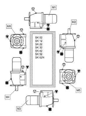
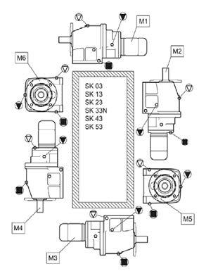
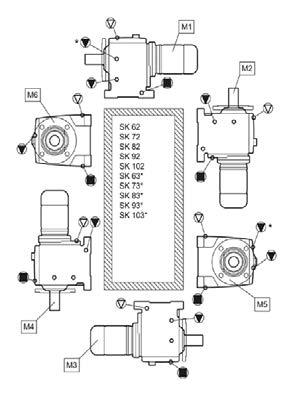
70 Explosion-protected gear units Operating and Assembly Instructions 70 B 2000 en-4217
71 6 Appendix B 2000 en


72 Explosion-protected gear units Operating and Assembly Instructions 72 B 2000 en-4217


73 6 Appendix B 2000 en
74 Explosion-protected gear units Operating and Assembly Instructions 74 B 2000 en-4217
75 6 Appendix B 2000 en
76 Explosion-protected gear units Operating and Assembly Instructions 76 B 2000 en-4217


77 6 Appendix B 2000 en
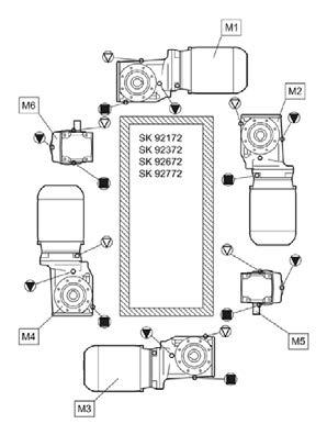
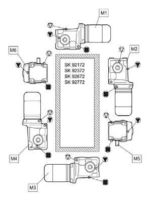
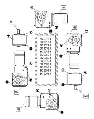
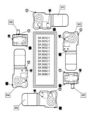
78 Explosion-protected gear units Operating and Assembly Instructions 78 B 2000 en-4217


79 6 Appendix B 2000 en
80 Explosion-protected gear units Operating and Assembly Instructions 80 B 2000 en-4217


81 6 Appendix B 2000 en
82 Explosion-protected gear units Operating and Assembly Instructions 82 B 2000 en-4217
83 6 Appendix 6.2 Lubricants DANGER! Explosion hazard Explosion hazard. Failure to comply may cause severe, or even fatal injuries. When changing oil or filling for the first time, the type of lubricant stated on the type plate must be used. The following table shows the approved proprietary brands or product names according to the gear oil types stated on the type plate (please see chapter 3.5 "Checking the type plate data"). This means that a product corresponding to the type of oil shown on the type plate must be used. In special cases, the designation of the specified product is stated on the type plate of the gear unit. Lubricant type Details on type plate Mineral oil CLP 220 CLP 100 Synthetic oil (Polyglycol) CLP PG 680 Synthetic oil (hydrocarbons) CLP PG 220 CLP HC 220 Alpha EP 220 Alpha SP 220 Optigear BM 220 Tribol 1100 / 220 Alpha EP 100 Alpha SP 100 Optigear BM 100 Tribol 1100 / 100 Alphasyn GS 680 Tribol 800 / 680 Alphasyn GS 220 Alphasyn PG 220 Tribol 800 / 220 Alphasyn EP 220 Tribol 1510/220 Optigear Synthetic X 220 Renolin CLP 220 Renolin CLP 220 Plus Renolin GEAR 220 VCI Renolin CLP 100 Renolin CLP 100 Plus Renolin PG 680 Renolin PG 220 Renolin Unisyn CLP 220 Renolin Unisyn Gear VCI Klüberoil GEM N Klüberoil GEM N Klübersynth GH Klübersynth GH Klübersynth GEM N Mobilgear 600 XP 220 Mobilgear 600 XP 100 Mobil Glygoyle 680 Mobil Glygoyle 220 Mobil SHC 630 Bio-degradable oil CLP E Plantogear 680 S Foodstuff compatible oil as per FDA CLP E 220 CLP PG H1 680 CLP PG H1 220 Table 14: Lubricant table Tribol BioTop 1418 / 220 Tribol FoodProof 1800 / 680 Tribol FoodProof 1800 / 220 CLP HC H1 680 Optileb GT 680 CLP HC H1 220 Optileb GT 220 Plantogear 220 S - - Cassida Fluid GL 680 Cassida Fluid GL 220 Klübersynth GEM Klübersynth UH Klübersynth UH Klüberoil 4 UH1-680 N Klüberoil 4 UH1-220 N - Mobil Glygoyle 680 Mobil Glygoyle 220 Mobile SHC Cibus 220 Omala S2 G 220 Omala S2 G 100 Omala S4 WE 680 Omala S4 WE 220 Omala S4 GX 220 Naturelle Gear Fluid EP 220 Cassida Fluid WG 680 Cassida Fluid WG 220 B 2000 en
84 Explosion-protected gear units Operating and Assembly Instructions 6.3 Torque values Dimensions Screw connections in the strength classes Bolt torques [Nm] Cover screws Threaded pin on coupling Screw connections on protective covers M M M M M M M M M M M M M M G½ G¾ G G1¼ G1½ Table 15: Torque values Assembling the hose fittings Oil the thread of the union nut, the cutting ring and the screw neck. Tighten the union nut with the wrench until the point where the union nut can only be turned with considerably more force. Turn the union nut of the screw fitting approx. 30 to 60 further but not more than 90. For this the screw neck must be held with a wrench. Remove excess oil from the screw fitting 84 B 2000 en-4217
85 6 Appendix 6.4 Troubleshooting WARNING Injury to persons There is a slipping hazard in case of leaks. Clean the soiled floor and machine components before starting troubleshooting. WARNING Injury to persons Risk of injury due to rapidly rotating and hot machine components. Troubleshooting must only be performed when gear units are at a standstill and have cooled down. The drive must be isolated and secured to prevent accidental start-up. NOTICE Gear unit damage Damage to the gear unit is possible in case of faults. Shut down the drive unit immediately in case of any faults in the gear unit. Unusual running noises, vibrations Oil escaping from the gear unit or motor Gear unit malfunctions Fault Possible cause Remedy Oil escaping from pressure vent Gear unit becomes too hot Shock when switching on, vibrations Output shaft does not rotate although motor is running Table 16: Overview of malfunctions Oil too low or bearing damage or gear wheel damage Defective seal Incorrect oil level or incorrect, contaminated oil or unfavourable operating conditions Unfavourable installation conditions or gear unit damage Defective motor coupling or loose gear unit mounting or defective rubber element Fracture in gear unit or defective motor coupling or shrink disc slippage Consult NORD Service Consult NORD Service Oil change, use oil expansion tank (Option OA) Consult NORD Service Replace elastomer gear rim, tighten motor and gear unit fastening bolts, replace rubber element Consult NORD Service B 2000 en
86 Explosion-protected gear units Operating and Assembly Instructions 6.5 Leakage and leak-tightness Gear units are filled with oil or grease to lubricate the moving parts. Seals prevent the escape of lubricants. A complete seal is technically not possible, as a certain film of moisture, for example on the radial shaft sealing rings is normal and advantageous for a long-term seal. In the region of vents, moisture due to oil may be visible due to the escape of oil mist because of the function. In the case of grease-lubricated labyrinth seals, e.g. Taconite sealing systems, used grease emerges from the sealing gap due to the principle of operation. This apparent leak is not a fault. According to the test conditions as per DIN 3761, the leak is determined by the medium which is to be sealed, which in test bench tests exceeds the function-related moisture in a defined test period and which results in dripping of the medium which is to be sealed. The measured quantity which is then collected is designated as leakage. Term Sealed Damp Wet Measurable leakage Temporary leakage Apparent leakage Definition of leakage according to DIN 3761 and its appropriate use Explanation No moisture apparent Moisture film locally restricted (not an area) Moisture film beyond the extent of the component Recognisable stream, dripping Temporary malfunction of the sealing system or oil leak due to transport *) Apparent leakage, e.g. due to soiling, sealing systems which can be relubricated Radial shaft seal No reason for complaint No reason for complaint No reason for complaint Repair recommended No reason for complaint No reason for complaint Location of leak In IEC adapter Housing joint Venting No reason for complaint No reason for complaint No reason for complaint Repair recommended No reason for complaint No reason for complaint No reason for complaint No reason for complaint Repair if necessary Repair recommended Repair if necessary No reason for complaint No reason for complaint No reason for complaint No reason for complaint Repair recommended No reason for complaint No reason for complaint Table 17: Definition of leaks according to DIN 3761 *) Previous experience has shown that moist or wet radial shaft sealing rings stop leaking later. Therefore, under no circumstances can replacement be recommended at this stage. The reason for momentary moisture may be e.g. small particles under the sealing lip. 86 B 2000 en-4217
87 6 Appendix 6.6 Declaration of Conformity Explosion protected gear units and geared motors, Category 2G and 2D Figure 31: Declaration of Conformity for Category 2G / 2D B 2000 en
88 Explosion-protected gear units Operating and Assembly Instructions Explosion protected gear units and geared motors, Category 3G and 3D Figure 32: Declaration of Conformity for Category 3G / 3D 88 B 2000 en-4217
89 6 Appendix 6.7 Repair information For enquiries to our technical and mechanical service departments, please have the precise gear unit type (type plate) and if necessary the order number (type plate) to hand Repairs The device must be sent to the following address if it needs repairing: Getriebebau NORD GmbH & Co. KG Service Department Getriebebau-Nord-Straße Bargteheide No guarantee can be given for any attachments, such as encoders or external fans, if a gear unit or geared motor is sent for repair. Please remove all non-original parts from the gear unit or geared motor. Information Reason for return If possible, the reason for returning the component or device should be stated. If necessary, at least one contact should be stated in case of queries. This is important in order to keep repair times as short and efficient as possible Internet information In addition, the country-specific operating and installation instructions in the available languages can be found on our Internet site: Abbreviations 2D Dust explosion protected gear units zone 21 FA Axial force 2G Explosion protected gear units with ignition IE1 Motors with standard efficiency protection class "c" 3D Dust explosion protected gear units zone 22 IE2 Motors with high efficiency ATEX ATmospheres EXplosibles IEC International Electrotechnical Commission B5 Flange fastening with through holes NEMA National Electrical Manufacturers Association B14 Flange fastening with threaded holes IP55 International Protection CW Clockwise, right-hand direction of rotation ISO International Standardisation Organisation CCW Counter-clockwise, left-hand direction of rotation ph ph value dh Water hardness in German hardness PPE Personal Protective Equipment degrees: 1 dh = mmol/l DIN German standards institute RL Directive EC European Community VCI Volatile Corrosion Inhibitor EN European standard WN Getriebebau NORD factory standard FR Radial transverse force B 2000 en
90 Explosion-protected gear units Operating and Assembly Instructions Key word index A Activating the vent Address Assembly C Check the oil level Coolant Cooling cover Correct use Coupling wear limits Covers D Danger labels Data on the type plate Disposal of materials F Faults G Gear unit types Bevel gear units Double gear units Helical gear units Helical worm gear units MINIBLOC NORDBLOC helical gear units Parallel shaft gear units Standard helical gear units UNIVERSAL worm gear units General overhaul General safety information H Hose fitting I Installing the gear unit Internet L Leakage Long-term storage Lubricant quantities for standard helical gear units Lubricant sensor Lubricants M Maintenance Maintenance intervals Maintenance work Changing the oil Check the oil level Cooling coil Coupling Hose Leaks Lubricant sensor Pressure venting Re-greasing VL2, VL3 and IEC Rubber buffer Running noises Shaft sealing ring Temperature sticker Motor weights for IEC adapters O Option H P Push-on gear unit R Repairs S Safety information... 2 Service Service intervals Shrink disc Standard motor B 2000 en-4217
91 Key word index Storage T Temperature sticker Test run Tightening torques Transport V Version testing B 2000 en

92 / 4217
B 1050 en. Industrial gear units. Operating and Assembly Instructions
 B 1050 en Industrial gear units Operating and Assembly Instructions Pos: 2 /Anleitungen/Getriebe/0. Prolog/Sicherheits- und Anwendungshinweise für Getriebe @ 3\mod_1375086447713_388.docx @ 84071 @ @ 1
1AM, 1UP, 2AM, 4AM, 6AM, 8AM, 16AM, NL22
 Ihr flexibler Problemlöser in der Fluidtechnik Compressed-air helical geared motors 1AM, 1UP, 2AM, 4AM, 6AM, 8AM, 16AM, NL22 with helical gearboxes SK DRUMAG GmbH Fluidtechnik Glarnerstrasse 2 79713 Bad
SEALING SOLUTIONS FOR YOUR DRIVES
 Intelligent Drivesystems, Worldwide Services SEALING SOLUTIONS FOR YOUR DRIVES EN SEALING SYSTEMS FOR NORD GEAR UNITS AND GEARED MOTORS SEALING SYSTEMS FOR NORD GEAR UNITS AND GEARED MOTORS NORD DRIVESYSTEM
Geared motors for use in Zone 22 - Category 3D
 Notes on the suitability of the gear units listed in this catalogue With the exception of variable speed gear units and industrial gear units, this catalogue contains all of the Getriebebau NORD gear unit
Type Operating Instructions. Bedienungsanleitung Manuel d utilisation. 2/2-way solenoid valve 2/2-Wege-Magnetventil Électrovanne 2/2 voies
 Type 5404 2/2-way solenoid valve 2/2-Wege-Magnetventil Électrovanne 2/2 voies Operating Instructions Bedienungsanleitung Manuel d utilisation Contents 1 Operating instructions...2 2 Intended use...3 3
BA EN.=A. Ä.=A.ä. Operating Instructions. Gearbox. Type 12. / 52.
 BA 12.0028 EN.=A. Ä.=A.ä Operating Instructions Gearbox Type 12. / 52. Product key Gearboxes 1 2... Product group Product family Gearbox size Design Geared motors 1 2... Product group Product family Gearbox
Assembly and Maintenance Manual Type ASNU
 Assembly and Maintenance Manual Type ASNU Hatschekstr.36 69126 Heidelberg Germany Tel +49(0)6221 30470 Fax +49(0)6221 304731 info@stieber.de www.stieber.de Date of issue: 30.05.2018 GB Revision: 0 U:\EngUsers\!ProduktDoku\1AAA_Einbauerklaerung_Wartungsanleitung_Konformitaetserklaerung\1AAA_Wartungsanleitungen\Orginal_Worddatei\_ASNU.docx
B 1091 en. Motors. Operating and Assembly Instructions
 B 1091 en Motors Operating and Assembly Instructions Motors Operating and Assembly Instructions 1 General Safety and operating instructions for electric motors (according to: Low Voltage Directive2006/95/EEC
Operating and Maintenance Instructions. Abteilung TB, Schell Seite 1 8 SERIES 56
 Abteilung TB, Schell Seite 1 8 These instructions supersede all earlier instructions, in particular BWS 109-0 till BWS 109-3. For applications in areas with explosion hazard it is obligatory to observe
Assembly and Maintenance Manual Type AS
 Assembly and Maintenance Manual Type AS Hatschekstr.36 69126 Heidelberg Germany Tel +49(0)6221 30470 Fax +49(0)6221 304731 info@stieber.de www.stieber.de Date of issue: 30.05.2018 GB Revision: 0 U:\EngUsers\!ProduktDoku\1AAA_Einbauerklaerung_Wartungsanleitung_Konformitaetserklaerung\1AAA_Wartungsanleitungen\Orginal_Worddatei\_AS.docx
B 2050 en. Industrial gear units. Operating and Assembly Instructions
 B 2050 en Industrial gear units Operating and Assembly Instructions Pos : 2 /Anl eitung en/getriebe/0. Prol og/sic her hei ts- und Anwendungs hinweis e für Getri ebe @ 3\mod_1375086447713_388.docx @ 84071
Type Operating Instructions. Bedienungsanleitung Manuel d utilisation. 2/2-way solenoid valve 2/2-Wege-Magnetventil Électrovanne 2/2 voies
 Type 6027 2/2-way solenoid valve 2/2-Wege-Magnetventil Électrovanne 2/2 voies Operating Instructions Bedienungsanleitung Manuel d utilisation 1 OPERATING INSTRUCTIONS The operating instructions contain
Type 6213 EV, 6281 EV
 Type 6213 EV, 6281 EV 2/2-way solenoid valve 2/2-Wege-Magnetventil Électrovanne 2/2 voies Operating Instructions Bedienungsanleitung Manuel d utilisation 1 OPERATING INSTRUCTIONS The operating instructions
Operating Instructions
 Operating Instructions Table of contents Table of contents... 1 1. Declaration... 1 2. Warranty and liability... 2 3. Gear description... 2 4. Gear types... 2 5. Safety... 3 5.1 General safety information...
X.. Series Helical and Bevel-Helical Gear Units
 SEW-EURODRIVE Easy Guide Industrial Gear Units X.. Series Helical and Bevel-Helical Gear Units Edition 05/2018 24803731/ EN 2/16 Gear unit structure 1 Safety notes 2 Gear unit designs 3 Mounting positions
ATEX LABELLING FOR MOTORS AND GEAR UNITS
 ATEX LABELLING FOR MOTORS AND GEAR UNITS EN ATEX INFORMATION GAS AND DUST COMPLETE DRIVE SOLUTIONS FROM A SINGLE SOURCE RELIABLE n Reliable products n Coordinated components n NORD's own development and
FLENDER ZAPEX couplings. Type ZWT. Operating instructions BA 3505 EN 10/2011. FLENDER couplings
 FLENDER ZAPEX couplings Type ZWT Operating instructions FLENDER couplings FLENDER ZAPEX couplings Type ZWT Operating instructions Translation of the original operating instructions Technical data Notes
Type Operating Instructions. Bedienungsanleitung Manuel d utilisation
 Type 0131 2/2- or 3/2-way solenoid valve 2/2- oder 3/2-Wege-Magnetventil Électrovanne 2/2 ou 3/2 voies Operating Instructions Bedienungsanleitung Manuel d utilisation 1 OPERATING INSTRUCTIONS The operating
BoWex FLE-PA. BoWex FLE-PAC. KTR-N Sheet: Edition: EN 1 of BoWex FLE-PA / FLE-PAC Operating/Assembly instructions
 1 of 17 is a torsionally rigid flange coupling. It is able to compensate for shaft misalignment, for example caused by manufacturing inaccuracies, thermal expansion, etc. BoWex FLE-PA BoWex FLE-PAC Drawn:
PTB 14 ATEX 2023 X, IECEx PTB X. Operating Instructions. Solenoid coil Type AC10 Magnetspule Typ AC10 Bobine magnétique Type AC10
 , IECEx PTB 14.0049X Solenoid coil Type AC10 Magnetspule Typ AC10 Bobine magnétique Type AC10 Device with II 2G/D Ex approval Geräte mit II 2G/D Ex Zulassung Appareils avec mode de protection II 2G/D Ex
Type 5411, Operating Instructions. Bedienungsanleitung Manuel d utilisation
 Type 5411, 5413 3/2 or 4/2 way solenoid valve 3/2 oder 4/2-Wege-Magnetventil Électrovanne 3/2 ou 4/2 voies Operating Instructions Bedienungsanleitung Manuel d utilisation 1 THE OPERATING INSTRUCTIONS The
Installation and Operating Instructions for ROBA-stop -Positioning Brake Type 80_.41_._ Sizes 3 11
 Please read and observe this Operating Instruction carefully! A possible malfunction or failure of the brake and any damage may be caused by not observing it. Table of contents: Page 1: Page 2: Page 3:
Operating Instructions
 BA 12.0028 450 298 EN Operating Instructions K12.0549 Typ Gearboxes 12.jjj 52.jjj Product key Gearboxes ➀ ➁ ➂ ➃ Product group Product family Gearbox size Design ➀ ➁ ➂ ➃ 12. 602. 20. 11 Geared motors ➀
FLENDER ARPEX Plate packs with close-fitting bolt connection. ARW-4 Sizes to Assembly instructions An 4239 en 12/2015.
 FLENDER ARPEX Plate packs with close-fitting bolt connection ARW-4 Sizes 101-4 to 292-4 Assembly instructions FLENDER couplings FLENDER ARPEX Plate packs with close-fitting bolt connection ARW-4 Sizes
EPS 16 ATEX 1072 X, IECEx EPS X. Operating Instructions. Solenoid coil Type AC19 Magnetspule Typ AC19 Bobine magnétique Type AC19
 , IECEx EPS 16.0030X Solenoid coil Type AC19 Magnetspule Typ AC19 Bobine magnétique Type AC19 Device with II 2G/D Ex approval Geräte mit II 2G/D Ex Zulassung Appareils avec mode de protection II 2G/D Ex
Installation and Operational Instructions for ROBATIC -clutch Types _.0 and _.0 Sizes 3 7
 Please read these Installation and Operational Instructions carefully and follow them accordingly! Ignoring these Instructions may lead to malfunction or to clutch failure, resulting in damage to other
Installation and Operational Instructions for EAS -Compact overload clutch, Type 49_. 4._ Sizes 4 and 5
 Please read these Operational Instructions carefully and follow them accordingly! Ignoring these Instructions may lead to malfunctions or to clutch failure, resulting in damage to other parts. Contents:
FLENDER ARPEX plate packs with conical bolting. ARP Size Assembly instructions AN 4256 en 07/2016. FLENDER couplings
 FLENDER ARPEX plate packs with conical bolting ARP Size 325-6 Assembly instructions FLENDER couplings FLENDER ARPEX plate packs with conical bolting ARP Size 325-6 Assembly instructions Translation of
FLENDER couplings. FLENDER ARPEX plate packs with conical bolting. ARS-6 sizes to K430 sizes 235 to 820
 FLENDER ARPEX plate packs with conical bolting ARS-6 sizes 255-6 to 722-6 K430 sizes 235 to 820 Operating instructions FLENDER couplings FLENDER ARPEX plate packs with conical bolting ARS-6 sizes 255-6
Installation and Operating Instructions for ROBA -ES couplings Type 940. _. _ Sizes 14-48
 Table of contents: Please read and observe this Operating Instruction carefully. A possible malfunction or failure of the clutch and damage may be caused by not observing it. Page 1: - Table of contents
Assembly and Operating Instructions
 A35AE FU...A150AE FU en Assembly and Operating Instructions Plug-in drives Important information for: Fitters / Electricians / Users Please forward accordingly! These instructions must be kept safe for
Type Operating Instructions. Bedienungsanleitung Manuel d utilisation. 2/2-Way Solenoid Valve 2/2-Wege-Magnetventil Électrovanne à 2/2 voies
 Type 5282 2/2-Way Solenoid Valve 2/2-Wege-Magnetventil Électrovanne à 2/2 voies Operating Instructions Bedienungsanleitung Manuel d utilisation 1 OPERATING INSTRUCTIONS The operating instructions contain
Operating Instruction
 Operating Instruction Drive element LEWA - ecosmart type LCA with manual stroke adjustment, motor mounted vertically Table of contents 1 General information / safety 1.1 Important preliminary information
RADEX -N Composite Operating/Assembly instructions
 1 of 14 RADEX -N is a torsionally stiff flexible steel lamina coupling. It is able to compensate for shaft misalignment, for example caused by thermal expansion, etc. note ISO 101. Drawn: 0.05.15 Kb/Wig
Exchange of rollers from the XTS-Mover
 Service documentation for AT901-0050-0550 and AT9011-00x0-0550 Version: Date: 1.0 0.10.017 Table of contents Table of contents 1 Foreword... 5 1.1 Notes on the documentation... 5 1. Documentation issue
Installation and operating instructions for elastic jaw coupling REK DCO. E e. Schaberweg Telephone
 elastic jaw coupling REK DCO E 06.696e Schaberweg 30-38 Telephone +49 6172 275 0 61348 Bad Homburg Fax +49 6172 275 275 Germany www.ringspann.com info@ringspann.com Page: 2 Important Before installation
Installation and Operational Instructions for ROBATIC -clutch Type and Type Sizes 3 9
 Please read the Operational Instructions carefully and follow them accordingly! Ignoring these Instructions may lead to malfunctions or to clutch failure, resulting in damage to other parts. Contents:
These operating instructions apply for: NCX 380 NCZ 300 NCX 480 NCZ 370 NCX 580 L NCZ 480 NCX 660 K NCZ 560 NCZ 660 NCZ 800
 Original instructions Operating Instructions for May 2010 Electric Internal Vibrators BA No. 1092E Series NCX and NCZ These operating instructions apply for: NCX 380 NCZ 300 NCX 480 NCZ 370 NCX 580 L NCZ
Assembly and maintenance manual Type FSO, FSO-GR, FS, HPI
 Type FSO, FSO-GR, FS, HPI Hatschekstr.36 69126 Heidelberg Deutschland Tel +49(0)6221 30470 Fax +49(0)6221 304731 info@stieber.de www.stieber.de Date of issue: 23.08.2018 GB Revision: 0 U:\EngUsers\!ProduktDoku\1AAA_Einbauerklaerung_Wartungsanleitung_Konformitaetserklaerung\1AAA_Wartungsanleitungen\Orginal_Worddatei\M1124E_0_FSO_FSO-GR_FS_HPI.docx
Operating manual. Custom made gearboxes
 Operating manual Custom made gearboxes DSS-Nr. 100389549 DSS-Rev. 001 Datum 16.01.2018 Contents Contents 1 General information 3 1.1 Using the operating manual 3 1.2 Warnings in this operating manual 4
CENTAFLEX-K Assembly and operating instructions 014K S... M EN Rev. 1
 Assembly and operating instructions Contents 1 General remarks... 5 2 Safety... 6 2.1 Qualification of deployed personnel... 6 2.2 Warning notes... 6 2.2.1 Signal words... 6 2.2.2 Symbols... 7 2.3 Application
Type Operating Instructions. Bedienungsanleitung Manuel d utilisation. 2/2-Way Solenoid Valve 2/2-Wege-Magnetventil Électrovanne à 2/2 voies
 Type 5282 2/2-Way Solenoid Valve 2/2-Wege-Magnetventil Électrovanne à 2/2 voies Operating Instructions Bedienungsanleitung Manuel d utilisation Contents 1 Operating Instructions... 2 2 Authorized use...
INTELLIGENT DRIVE SYSTEMS, WORLDWIDE SERVICES INTELLIGENT DRIVESYSTEMS, WORLDWIDE SERVICES
 INTELLIGENT DRIVE SYSTEMS, WORLDWIDE SERVICES INTELLIGENT DRIVESYSTEMS, WORLDWIDE SERVICES EN DRIVE SOLUTIONS FOR SEWAGE PLANTS NORD DRIVESYSTEMS Intelligent Drivesystems, Worldwide Services NORD DRIVE
Installation and Operational Instructions for EAS - HTL housed overload clutch Sizes 01 3 Type 490._24.0
 Please read these Operational Instructions carefully and follow them accordingly! Ignoring these Instructions may lead to malfunctions or to clutch failure, resulting in damage to other parts. Contents:
Safety. Operating instructions Solenoid valve for gas VG 6 VG 15/10 DANGER. Contents WARNING CAUTION. Changes to edition 07.15
 17 Elster GmbH Edition 1.17 Translation from the German 519 D F NL I E DK S N P GR TR CZ PL RUS H www.docuthek.com Operating instructions Solenoid valve for gas VG VG 15/1 Contents Solenoid valve for gas
Operation manual Flexible pin type coupling according to KWN 22014
 Operation manual Flexible pin type coupling according to KWN 22014 Author: Dipl.-Ing.. V. Hausdorf 24.01.2005 gez. V. Hausdorf Approved: Dr.-Ing. Ch. Spensberger 24.01.2005 gez. Dr.-Ing. Ch. Spensberger
EPS 16 ATEX 1121 X, IECEx EPS X Solenoid coil Type 06xx Magnetspule Typ 06xx Bobine magnétique Type 06xx. Operating Instructions
 , IECEx EPS 16.0053X Solenoid coil Type 06xx Magnetspule Typ 06xx Bobine magnétique Type 06xx Device with II 2G/D Ex approval Geräte mit II 2G/D Ex Zulassung Appareils avec mode de protection II 2G/D Ex
Instructions for Fitting, Operating and Maintenance Canopy Door RE / (St.: )
") EN Instructions for Fitting, Operating and Maintenance Canopy Door 1 818 012 RE / (St.: 12.2010) 12.2010 ENGLISH Contents 1 Safety Instructions... 3 1.1 Qualified persons... 3 1.2 Symbols and signal words
EN Instructions for Fitting, Operating and Maintenance Canopy Door 1 818 012 RE / (St.: 12.2010) 12.2010 ENGLISH Contents 1 Safety Instructions... 3 1.1 Qualified persons... 3 1.2 Symbols and signal words
Installation and Operating Instructions
 Original Installation and Operating Instructions Hawle E2 Valve with Flange Outlet, System 2000 or PE Spigot Ends Table of Contents A) General...... 2 A1 Symbols..... 2 A2 Intended use... 2 A3 Labeling...
LUBRICATION, INSTALLATION, OPERATION & MAINTENANCE INSTRUCTIONS FOR STAINLESS STEEL CONE DRIVE SPEED REDUCERS
 LUBRICATION, INSTALLATION, OPERATION & MAINTENANCE INSTRUCTIONS FOR STAINLESS STEEL CONE DRIVE SPEED REDUCERS Cone Drive double-enveloping worm gear speed reducers are used throughout industry to provide
Installation and Operational Instructions for EAS -Compact overload clutch Type 49_. 4._ Sizes 01 to 3
 Please read these Operational Instructions carefully and follow them accordingly! Ignoring these Instructions may lead to malfunctions or to clutch failure, resulting in damage to other parts. Contents
Operating and Installation Instructions Diaphragm Vacuum Pumps and Compressors
 Operating and Installation Instructions Diaphragm Vacuum Pumps and Compressors Type range: UN813.3ANI UN813.4ANI UN813.3ANDCB UN813.4ANDCB UN813.5ANI Fig. 1: UN813.3ANI Fig. 2: UN813.4ANI You have selected
CENTAX-SEC Series B Assembly and operating instructions CX BFS1-LE/SE-**-B M EN Rev. 1
 Assembly and operating instructions -**-B Contents 1 General remarks... 5 2 Safety... 6 2.1 Safety remarks... 6 2.1.1 Signal words... 6 2.1.2 Pictograms... 7 2.2 Qualification of deployed personnel...
Appendix: Safety and application notes for... 15
 Contents Safety... 2 Warnings... 2 Symbols used in this manual... 2 Operator s safety... 2 Avoid filter module damage... 2 DC-link resonance... 2 Description... 3 Description... 3 Ordering numbers, 380-415
Safety. Operating instructions Solenoid valve VGP DANGER. Contents WARNING CAUTION. Changes to edition Elster GmbH Edition 10.
 27 Elster GmbH Edition.7 Translation from the German 344297 D F NL I E DK S N P GR TR CZ PL RUS H www.docuthek.com Operating instructions Solenoid valve Contents Solenoid valve... Contents... Safety....
Original operation instructions Worm gear units S40.1 S450.1
 Translation of the Original operation instructions AUMA Drives GmbH Grenzstraße 5 D-01640 Coswig/ Germany Phone: +49 (0) 3523 94 60 Fax: +49 (0) 3523 74 675 www.auma-drives.com AUMA Drives Service Phone:
Installation and Operating Instructions for EAS -NC clutch Type 45_. _. _ Sizes 02 and 03
 Table of contents: Please read and observe this Operating Instruction carefully! A possible malfunction or failure of the clutch and any damage may be caused by not observing it. Page 1: - Table of contents
PO Box 645, Stockton, Missouri, FAX superiorgearbox.com
 I000-7000-D0447-A 4/7/05 1 SAFETY PRECAUTIONS CAUTION Please read this entire document prior to operating the gear drive. Gear drive failure and / or injury to operators may be caused by improper installation,
Turbocharger / A100-L Original assembly instructions English
 Assembly Instructions Turbocharger / A100-L Original assembly instructions English This document is valid for the A100-L series: A165-L, A170-L, A175-L, A180-L, A185-L, A190-L Purpose The assembly instructions
These installation and maintenance instructions must be read in full and completely understood before the installation!
 These installation and maintenance instructions must be read in full and completely understood before the installation! 1. General information on the installation and maintenance instructions These instructions
Installation and Operating Instruction for Brake Caliper HW 150 HFA and HW 180 HFA E e
 Installation and Operating Instruction for Brake Caliper HW 150 HFA and HW 180 HFA E 09.736e Schaberweg 30-38 Phone +49 6172 275-0 61348 Bad Homburg Fax +49 6172 275-275 Germany www.ringspann.com info@ringspann.com
SERVO MOTORS BRUSHLESS SERVO MOTORS OPERATING INSTRUCTIONS 2016
 SERVO MOTORS BRUSHLESS SERVO MOTORS OPERATING INSTRUCTIONS 2016 3009/16 en Ed.02.2016 Read these Operating Instructions before performing any transportation, installation, commissioning, maintenance or
CENTAX-TEST Assembly and operating instructions 053C GB3. M EN Rev. 1
 Assembly and operating instructions Contents 1 General remarks... 5 2 Safety... 6 2.1 Safety remarks... 6 2.1.1 Signal words... 6 2.1.2 Pictograms... 7 2.2 Qualification of deployed personnel... 7 2.3
PTB 14 ATEX 2023 X, EPS 16 ATEX 1046 X. Operating Instructions. Solenoid coil Type AC10 Magnetspule Typ AC10 Bobine magnétique Type AC10
 PTB 14 ATEX 2023 X, EPS 16 ATEX 1046 X Solenoid coil Type AC10 Magnetspule Typ AC10 Bobine magnétique Type AC10 Device with II 2G/D Ex approval Geräte mit II 2G/D Ex Zulassung Appareils avec mode de protection
Installation, Operating and Maintenance Instructions Retractable Door / Art.-Nr.:
 Installation, Operating and Maintenance Instructions Retractable Door 06.2008 / Art.-Nr.: 1 818 024 ENGLISH CONTENTS PAGE 1 SAFETY REQUIREMENTS 3 1.1 Symbols and key words used 3 1.2 Designated use 3 1.3
Type 0283, Operating Instructions. Bedienungsanleitung Manuel d utilisation. 2/2-way solenoid valve 2/2-Wege-Magnetventil Électrovanne 2/2 voies
 Type 0283, 0293 2/2-way solenoid valve 2/2-Wege-Magnetventil Électrovanne 2/2 voies Operating Instructions Bedienungsanleitung Manuel d utilisation Contents 1 The operating instructions...2 2 Intended
Operating Instructions
 Operating Instructions Pendant Light Fitting > Contents 1 Contents 1 Contents...2 2 General Information...2 3 General Notes Regarding Safety...3 4 Intended Area of Application...4 5 Technical Data...5
PLS / WPLS / PLV / PLS-HP / PLF-HP PLN / WPLN / WGN / PLFN PSN / PSFN PLE / WPLE / PLFE PLPE / WPLPE / PLHE
 Instruction Manual Standard Planetary Gearbox PLS / WPLS / PLV / PLS-HP / PLF-HP PLN / WPLN / WGN / PLFN PSN / PSFN PLE / WPLE / PLFE PLPE / WPLPE / PLHE GB_ 100225283 / Rev. Stand 004 www.zetek.ru +7(495)
Technical Documentation
 Technical Documentation Product manual Holding brake controller Document: 0198441113316 Edition: V1.00, 03.2006 Important information The drive systems described here are products for general use that
Maintenance Instructions
 General Note These instructions contain information common to more than one model of Bevel Gear Drive. To simplify reading, similar models have been grouped as follows: GROUP 1 Models 11, 0, 1,, (illustrated),,
FLENDER COUPLINGS N-EUPEX. Operating Instructions 3103en Edition 10/2017 O, P
 FLENDER COUPLINGS N-EUPEX Operating Instructions 3103en Edition 10/2017 O, P 21.09.2017 16:21 V6.00 Introduction 1 Safety instructions 2 FLENDER COUPLINGS N-EUPEX 3103en Operating Instructions Description
Type Operating Instructions. Bedienungsanleitung Manuel d utilisation
 2/2-way angle seat control valve 2/2-Wege-Schrägsitzregelventil Vanne de réglage à siège incliné 2/2 voies Operating Instructions Bedienungsanleitung Manuel d utilisation We reserve the right to make technical
Installation and Operating Manual for Tank and Equipment Cleaning Nozzles Series 5TM
 Installation and Operating Manual for Tank and Equipment Cleaning Nozzles Series 5TM 150 150 150 This instruction manual contains proprietary information which is protected by copyright laws. No part of
INDUSTRY PROCESS AND AUTOMATION SOLUTIONS. Technical Bulletin
 INDUSTRY PROCESS AND AUTOMATION SOLUTIONS Technical Bulletin Guidelines for selection of planetary gear units of the 300- INDUSTRIAL series for installation in hazardous areas, classified by Directive
VEM motors Thurm GmbH
 VEM motors Thurm GmbH Installation, Operating and Maintenance Instructions Single-Phase Squirrel-Cage Induction Motors, Standard Version March 2005 1. General To avoid damage to the motors and equipment
Assembly and Maintenance Manual Type RSBW
 Assembly and Maintenance Manual Type RSBW Hatschekstr. 36 69126 Heidelberg Germany Tel +49(0)6221 30470 Tel +49(0)6221 304731 info@stieber.de www.stieber.de Stieber Clutch Date of issue: 16/03/2017 GB
General operating manual for assembly, commissioning and maintenance of valves and hydraulic manifolds
 for assembly, commissioning and maintenance of valves and hydraulic manifolds 110210_general_operating_manual 07.2018 Table of contents Contents Page Important information 2 Important safety instructions
Swing Piston Compressors and Vacuum Pumps
 Swing Piston Compressors and Vacuum Pumps NPK 050 NPK 0100 Operating and Installation Instructions Read and observe these Operating and Installation Instructions! KNF Neuberger GmbH Alter Weg 3 D-79112
Installation and Operational Instructions for ROBA-stop Holding Brake Type _._
 Please read these Installation Instructions carefully and follow them accordingly! Ignoring these Instructions may lead to malfunctions or to brake failure, resulting in damage to other parts. Contents:
Original operation instructions GFC escalator gear units FTSST158.1, FTSST180.1, FTSST212.1
 Translation of the Original operation instructions GFC escalator gear units FTSST158.1, FTSST180.1, FTSST212.1 AUMA Drives GmbH Grenzstraße 5 D-01640 Coswig/ Germany Phone: +49 (0) 3523 94 60 Fax: +49
RWB, RBS. Operating Instructions. FLENDER couplings RUPEX. 3602en. Edition 03/2017.
 RWB, RBS Operating Instructions FLENDER couplings RUPEX 3602en Edition 03/2017 www.siemens.com/drives 05.04.2017 08:57 V5.02 Introduction 1 Safety instructions 2 RUPEX FLENDER couplings 3602en Operating
Toothed belt axis ELGC-TB-KF. Operating instruction [ ]
![Toothed belt axis ELGC-TB-KF. Operating instruction [ ]](/thumbs/83/87984161.jpg "Toothed belt axis ELGC-TB-KF. Operating instruction [ ]") Toothed belt axis ELGC-TB-KF en Operating instruction 8068220 2017-02 [8068222] Original instructions Identification of hazards and instructions on how to prevent them: Danger Immediate dangers which can
Toothed belt axis ELGC-TB-KF en Operating instruction 8068220 2017-02 [8068222] Original instructions Identification of hazards and instructions on how to prevent them: Danger Immediate dangers which can
D, E, M. Operating Instructions. FLENDER couplings N-EUPEX. 3102en. Edition 03/2017.
 D, E, M Operating Instructions FLENDER couplings N-EUPEX 3102en Edition 03/2017 www.siemens.com/drives 30.03.2017 11:11 V5.02 Introduction 1 Safety instructions 2 N-EUPEX FLENDER couplings 3102en Operating
Oil-free piston compressors KK and piston vacuum pumps KV
 Oil-free piston compressors KK and piston vacuum pumps KV Installation and Operating Instructions 0678106030L02 1707V003 Contents Important information 1 About this document 2 1.1 Warnings and symbols
BUTTERFLY VALVE WITH WELDED ENDS INSTALLATION AND MAINTENANCE MANUAL
 BUTTERFLY VALVE 31300 SERIES INSTRUCTIONS FOR INSTALLATION, USE AND MAINTENANCE 1. Overview Read these instructions carefully before starting the valve installation and start-up work. Safe keep the instructions
Assembly Instructions
 Drive Technology \ Drive Automation \ System Integration \ Services *2450452_0617* Assembly Instructions Didactics - Gear Unit Technology Helical Gear Unit R57F AD2 Edition 06/2017 2450452/EN SEW-EURODRIVE
Quarter turn actuator DAPS..R..-F..
 Quarter turn actuator DAPS..R..-F.. Festo AG & Co. KG Postfach D-73726 Esslingen +49 711 347-0 www.festo.com (en) Operating instructions 8030408 1309g [8030416] Original: de Quarter turn actuator DAPS..R..-F.....
Installation and Operating Instructions Magnetic Vibrator MR 1
 Installation and Operating Instructions Magnetic Vibrator MR 1 (Translation of the Original Instruction Manual) Würges Vibrationstechnik GmbH Daimlerstraße 9 D-86356 Neusäß Telephone +49 821 999824-00
Part-turn gearboxes GS 50.3 GS 250.3
 Part-turn gearboxes GS 50.3 GS 250.3 Operation instructions Assembly, operation, commissioning Table of contents GS 50.3 GS 250.3 Read operation instructions first. Observe safety instructions. These operation
HST -LS Interlocking device (Translation of Original Manual)
") Installation and Operating Manual for Components HST -LS Interlocking device (Translation of Original Manual) HST-LS Ident.-No.: 10268 HST-LS Ident.-No.: 10269 HST-LS, pictured Ident-Nr. 10269 The image
Installation and Operating Manual for Components HST -LS Interlocking device (Translation of Original Manual) HST-LS Ident.-No.: 10268 HST-LS Ident.-No.: 10269 HST-LS, pictured Ident-Nr. 10269 The image
Operating / Assembly Instructions Type A and CS Coupling
 Page: 1 of 14 Subject Index 1. Technical Data 2. Hints 2.1. General Hints 2.2. Warning and Safety Hints. 2.3. General Hints to Danger. 2.4. Proper use. 3. Storage. 4. Assembly. 4.1. Coupling components.
MECHANICAL CYLINDERS Operating Instructions
 SW3001EN.1 MECHANICAL CYLINDERS Operating Instructions Sweden Int +46 372 265 00 info@swedrive.se Vat.no SE556145631901 138-4551 1 Table of Contents 1. Health and Safety... 3 1.1. Notice about safety...
Turbocharger / VTR..0, VTR..1 Original assembly instructions English
 Assembly Instructions Turbocharger / VTR..0, VTR..1 Original assembly instructions English This document is valid for the VTR..0/..1 series: VTR160, VTR200, VTR250, VTR320, VTR400 VTR161, VTR201, VTR251,
Instructions for Fitting, Operating and Maintenance
 EN Instructions for Fitting, Operating and Maintenance Retractable Door 1 818 024 RE / 10.2011 ENGLISH Contents 1 Safety Instructions... 3 1.1 Qualified persons... 3 1.2 Symbols and signal words used...
Instruction Manual for HSPA Take-Up Units
 Installation Instruction Manual for HSPA Take-Up Units Warning: To ensure the drive is not unexpectedly started, turn off and lockout the power source before proceeding. Failure to observe these precautions
Pressure relief valve
 Pressure relief valve Operating manual Series DHV 712 Version BA-2015.10.20 EN Print-No. 300 510 TR MA DE Rev001 ASV Stübbe GmbH & Co. KG Hollwieser Straße 5 32602 Vlotho Germany Phone: +49 (0) 5733-799-0
FLENDER COUPLINGS N-EUPEX / N-EUPEX DS. Operating Instructions 3100en Edition 10/2017 A, B, ADS, BDS
 FLENDER COUPLINGS N-EUPEX / N-EUPEX DS Operating Instructions 3100en Edition 10/2017 A, B, ADS, BDS 21.09.2017 14:39 V6.00 Introduction 1 Safety instructions 2 FLENDER COUPLINGS N-EUPEX / N-EUPEX DS 3100en
Quick-Disconnect Coupling one-hand operation Push Pull ND 5, connecting thread G 1/4,max. operating pressure 500 bar
 Issue 12-2013 Quick-Disconnect Coupling one-hand operation Push Pull ND 5, connecting thread G 1/4,max. operating pressure 500 bar Figure 1: Coupling complete Figure 4: Coded coupling, complete Table of
Lenze ATEX-compliant gearboxes Gearboxes for use in potentially explosive atmospheres
 Lenze ATEX-compliant gearboxes Gearboxes for use in potentially explosive atmospheres ATEX for drive technology The ATEX directive, which has been in force since July 1, 2003, has been introduced in an
CENTAFLEX-H Assembly and operating instructions 008H /3000 M EN Rev
 008H-00400-1000/3000-1000 -3000-1000 -3000 Contents 1 General remarks... 5 2 Safety... 6 2.1 Safety remarks... 6 2.1.1 Signal words... 6 2.1.2 Pictograms... 7 2.2 Qualification of deployed personnel...