ADDING A NEW DIMENSION TO MACHINE PRODUCTIVITY! UPGRADE MACHINE PERFORMANCE & PROFITABILITY! Designed & Made in USA UPGRADE TO PFA! pfa-inc.
|
|
|
- Arabella George
- 6 years ago
- Views:
Transcription


1 ADDING A NW DIMNSION TO MACHIN PRODUCTIVITY! UPGRAD MACHIN PRFORMANC & PROFITABILITY! Designed & Made in USA UPGRAD TO PFA!
, Multi-Slide Die Casting Solutions, and Robotic Automation nd-ffectors. Our staff is committed to providing you with the best possible products and service.")
2 Located just North of Milwaukee, Wisconsin, PFA is a leader in the design and manufacture of Quick Die Change Systems (QDC), Specialty Injection Mold Components, Specialty Industrial Cylinders, Quick Mold Change Systems (QMC), Multi-Slide Die Casting Solutions, and Robotic Automation nd-ffectors. Our staff is committed to providing you with the best possible products and service. PFA offers a wide array of standard products plus custom solutions for especially challenging applications. Contact us with your needs. We will be glad to serve you! N118 W18251 Bunsen Drive Germantown, WI (262) Fax (262) www. 2 SLF-LOCKING & BRAKING CYLINDRS BY PFA, INC.
3 SWITCHMAX Connectivity Components and lectrical Cables integrate various on mold sensors (relay, mechanical, and proximity DC) into a single signal interface common on most injection molding machines. LD indication also assists operators. No more complex wiring just plug & play. Robotic Automation nd ffectors. Modular products allow the coupling of Grippers, Gripper Pads (GP), Compliance Devices (RCC) and Crash Protection (OPD) into a simple and integrated robotic end-effector solution. Quick Die Change Systems provide easily customized solutions for stamping die quick change. Bolster extensions, die rails/lifters, check valve and locking clamps, and electronic 5,000 psi pump controllers are just a few of the options available. Hydra-Jaws Quick Mold Change and Hydra- Latch Quick Knockout Systems provide consistent clamping and support rapid mold changes for a wide range of mold sizes in a single machine. Clamps move to fit the mold! KOR-LOK Side-Action Systems and DI-LOK Multislide Systems for pre-loading and locking moveable cores on injection molds and die cast dies, provide improved part quality, speed and performance over traditional cam pin and toggle methods. CONTNTS Why Self-Locking & Braking Cylinders? Cylinder Comparisons...4 HYS/PVS - Hydraulic/Pneumatic Self-Locking Cylinders...5 Lock-On xtend (LO) Style Lock-On Retract (LOR) Style KPS Internal Braking Cylinder...5 Self-Locking Cylinders (HYS/PVS) Lock on xtend (LO)...6 Dimensional Information...7 How to Order...9 Lock on Retract (LOR)...10 Dimensional Information...11 How to Order...13 KPS Braking Cylinders General Specifications...14 Dimensional Information...15 How to Order...17 NOT: All products are assumed to be operated with due regard to safety and at proper pressures. Note specifically that PVS cylinders are primarily pneumatic with the ability to operate with hydraulics at very limited pressures. KPS cylinders are pneumatic only. Selection of any product for any application is the responsibility of the customer. PFA assistance and recommendations are not a substitute for proper review and selection by the customer. PFA Terms of Sale apply. Dimensions are provided for reference only and subject to change without notice. Contact PFA regarding critical dimensions for any application prior to ordering. Why Self-Locking and Braking Cylinders Self-Locking Cylinders Braking Cylinders SLF-LOCKING & BRAKING CYLINDRS BY PFA, INC. 3
4 WHY SLF-LOCKING & BRAKING CYLINDRS? Self-Locking Cylinders and Brake Cylinders allow designers to defeat common barriers associated with hydraulic and pneumatic systems. Locking Cylinders: Repeatable precise positioning along with high force holding capability is now attainable with PFA Self- Locking Cylinders. The metal-on-metal positive lock ensures hard contact repeatability and maintains position independent of system pressure. Because the locking mechanism physically blocks rod movement, common spongy air and hydraulic problems are eliminated. Once in the locked position, system pressure may be lost or removed without affecting position or load capacity. Braking Cylinders: Holding the rod in position when air pressure is lost is the typical use of PFA s Braking Cylinders. The internal rod brake allows holding in any position. MODULAR SUPPORT PFA s modular systems replace custom and complex systems, allowing for drop-in support. That means that during production runs, when your customers need to do a quick replacement, they can do it. DISCOVR TH BNFITS OF CONTROL, PROTCTION, STRNGTH AND ASY OPRATION WITH PFA SLF-LOCKING CYLINDRS! Mechanical Lock Protection. True rod interrupt lock ensures full load capacity is maintained, even if system pressure is lost! (HYS/PVS) Positive Locking Sensor Control. Senses actual locking action engaging to ensure positive machine control. Smooth & asy Operation. Complementary angles allow for ease of lock engagement and disengagement even under load! Strong Compact Design. Integral locking mechanism allows for ease of installation and can hold the force of a cylinder 10 to 15 times larger! Standard Porting Flexibility. When cylinder reaches end of stroke the spring bias causes the lock to engage. Retract pressure (LO) or extend pressure (LOR) is ported internally to unlock the unit, making a 2-port system. (HYS/PVS) SOM XAMPLS Lift and load devices, safety mechanisms, and non-drift applications are just three generic examples of possible uses. Specific examples include: foam molding, intermittent use lifting, movable platforms, staking, automated assembly, tooling fixtures, stamping, packaging and many more. Adjustable nd of Stroke Cushioning. Metered exhaust YS! allows for adjustable cushions at either end of stroke. (HYS/ PVS/KPS) 4 SLF-LOCKING & BRAKING CYLINDRS BY PFA, INC. COMPARISON TO STANDARD CYLINDRS YS! YS! YS! YS! SIMPLR IS BTTR! Often by eliminating the need for hydraulics, our pneumatic Self-Locking Cylinders and Braking Cylinders do the job better, faster, and at a lower cost, saving money in design, construction, and lifetime operation. For amazing hydraulic versions with 10x the holding force of standard hydraulic cylinders, try our HYS series. PFA OTHR SLF-LOCKING VS. STANDARD CYLINDRS CYLINDRS Move loads based on applied pressure? Maintain position/force with pressure drops? Keep position/force with total loss of pressure? Hold loads up to 15 times the piston force? Perform intermittent operation with zero drift? YS! CAN T DO IT! CAN T DO IT! CAN T DO IT! CAN T DO IT!
5 HYS/PVS - HYDRAULIC/PNUMATIC SLF-LOCKING CYLINDRS LOCK-ON-XTND (LO) STYL (see page 6) APPLICATION The Lock-on-xtend (LO) Self-Locking Cylinder locks the rod in position when the rod is fully extended. Load force is applied to the rod in a direction such that it is pushing on the rod (compression). Lock prevents retraction. OPRATION The Lock-on-xtend (LO) Self-Locking Cylinder employs a tri-sectional locking ring (three segments) and an annular groove to maintain a metal-on-metal mechanical lock regardless of system pressure. As the cylinder reaches end-of-stroke (extend), the trisectional ring is forced into the annular groove in the rod by the locking slide. The locking slide is held in place by the bias springs and will maintain lock-up until pressure is applied to the retract port. The retract port supplies pressure to move the locking slide off the three locking segments and to retract the rod at the same time. LOCK-ON-RTRACT (LOR) STYL (see page 10) APPLICATION The Lock-on-Retract (LOR) Self-Locking Cylinder locks the rod in position when the rod is fully retracted. Load force is applied to the rod in a direction such that it is pulling on the rod (tension). Lock prevents extension. OPRATION The Lock-on-Retract (LOR) Self-Locking Cylinder employs a tri-sectional locking ring (three segments) and an annular groove to maintain a metal-on-metal mechanical lock regardless of system pressure. As the cylinder reaches end-of-stroke (retract), the rod engages a keeper slide allowing the tri-sectional ring is forced into the annular groove by the locking slide. The locking slide is held in place by the bias springs and will maintain lock-up until pressure is applied to the extend port. The extend port supplies pressure to move the locking slide off the three locking segments and to extend the rod at the same time. KPS INTRNAL BRAKING CYLINDR (see page 14) S IN MOTION AT APPLICATION The KPS Internal Braking Cylinder is designed for long life when properly utilized. Ideally, the brake element should be engaged when the piston rod is no longer moving. Braking with the cylinder rod stationary will reduce the wear of the braking element and allow for precise positioning. Brake holds rod in any position. Why Self-Locking and Braking Cylinders Self-Locking Cylinders Braking Cylinders OPRATION PFA s KPS Internal Braking Cylinder provides the freedom to stop and hold a load anywhere along the stroke, without relying on air pressure to hold position. While the KPS functions like any other double-acting pneumatic cylinder during normal cycling, when air pressure is removed from the brake port the internal spring-loaded brake mechanism will engage. The brake mechanism consists of spring washers, cone, brake piston and mandrel. When air pressure is removed from the brake port, the spring washers force the piston to pull the cone into the brake mandrel. As the cone enters the brake mandrel, the mandrel (similar to a collet) is forced to spread, contacting the inside surface of the piston rod and effectively holding it in place. When pressure is applied to the release side of the brake piston, the spring washers are compressed, relieving tension on the brake mandrel and releasing the piston rod. The KPS cylinder rod is now free to move. SLF-LOCKING & BRAKING CYLINDRS BY PFA, INC. 5

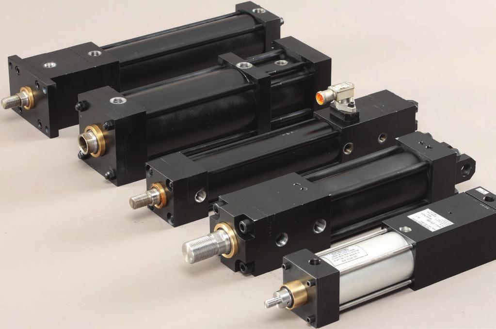
 HYS Style Self-Locking Cylinders are commonly used for applications where high moving forces are required.")

6 SLF-LOCKING CYLINDRS (HYS/PVS) LOCK-ON-XTND S IN MOTION AT C A B LOCK ON XTND (LO) CYLINDR TYPS PVS (PNUMATIC/AIR/LIGHT HYDRAULIC) PVS Style Self-Locking Cylinders are commonly used for applications using air. Often the PVS model replaces or substitutes for more costly hydraulic systems. The solid metal-on-metal lock allows for high loading without the squish associated with standard air cylinders. HYS (HAVY HYDRAULIC) HYS Style Self-Locking Cylinders are commonly used for applications where high moving forces are required. HYS is the perfect choice in applications where holding during loss of pressure is critical. The Heavy Hydraulic style may be operated pneumatically in some applications. Consult PFA for details. ACCOMMODATION OF LOCKING CLARANC / OVRTRAVL Self-Locking Cylinders must fully extend to lock at the end of stroke. In many applications, the lock point is not restricted and the cylinder fully extends and locks. In other applications, a more precise lockup window is desirable and may be obtained with simple stops and shims. To ensure locking, the cylinders are manufactured with.004 to.013 of overtravel (end play) beyond the seating lock position. When pressure is removed or load applied after a locked condition is achieved, the rod will backup or move until the clearance is taken up. The overtravel clearance may be eliminated by adjusting load position at the rod-to-load interface. Consult a PFA Applications Specialist for details. HOW IT WORKS As the cylinder reaches end-of-stroke, the tri-sectional ring (A), is forced into the annular groove (B) in the rod by the locking slide ( C ). The locking slide is held in place by the bias springs and will maintain lock-up until pressure is applied to the retract port. The retract port supplies pressure to move the locking slide off the three locking segments and to retract the rod at the same time. 6 SLF-LOCKING & BRAKING CYLINDRS BY PFA, INC.
7 DIMNSIONAL INFORMATION (All Dimensions nominal and in inches) FC2 FC1 LOAD 'A' 'B' 'C' 'D' NOT: Application sketches are offered as suggestions only. Feasibility, testing and usage of the product is the responsibility of the user. The product may be used to increase safety, but should not replace positive stop safety mechanisms. No liability is expressed or intended on the part of PFA, Inc., it s employees or agents. SIMPLIFID CIRCUIT/SQUNC- VRTICAL MOVMNT To support the vertical load and remove force on the lock prior to unlocking and lowering (with possible multiple speeds). 1. Valve CD is recommended in vertical applications to prevent uncontrolled dropping or movement of the load due to gravity when unlocked. 2. NSUR LOAD IS GUIDD INDPNDNTLY from the cylinder rod in vertical applications. 3. nergize solenoid (C) to lift/support the load off of the locking mechanism. 4. Leave (C) energized while energizing (A) to unlock the locking Mechanism (lock sensor off). 5. De-energize (C) to lower load at speed set at (FC1). 6. nergize (D) to lower load at higher speed based on parallel (combined) flow thru (FC1) and (FC3). 7. nergize (B) to lift the load with speed based on (FC2). At full extend the cylinder will lock (sensor on to verify lock). LOCK-ON-XTND (LO) THORTICAL PRFORMANC DATA Lock-on-xtend Style Bore ø / Rod ø FC3 Lock Holding Force** (Fully xtended) (LBS) Max Operating Pressure (psi) ffective Area xtend (sq.in.) ffective Area Retract (sq.in.) SIMPLIFID CIRCUIT/SQUNC- HORIZONTAL MOVMNT To allow for more simple horizontal cylinder operation. 1. Valve CD is not needed in the horizontal application, IF the lock is NOT under load during unlocking. However, if the lock IS under load during unlocking, then follow the Vertical movement method. 2. NSUR LOAD IS SUPPORTD INDPNDNTLY from the cylinder rod in a horizontal application. 3. With no load on the lock, nergize A to unlock and retract at speed set by (FC1). 4. nergize (B) to extend the load at speed set at (FC2). Maximum xtend Force (LBS)*** Maximum Retract Force (LBS)*** PVS / ,500 1, ,140 2,830 PVS / ,000 1, ,910 4,120 PVS / ,500 1, ,570 11,090 PVS / , ,730 12,915 PVS / , ,202 19,425 HYS / ,000 3, ,420 7,050 HYS / ,000 3, ,730 10,290 HYS / ,000 3, ,710 30,480 Why Self-Locking and Braking Cylinders Self-Locking Cylinders Braking Cylinders * Heavy Hydraulic Style may be operated pneumatically in some applications. Consult PFA for details. ** Cylinder locking / holding force is a function of rod column strength and depends on overall stroke length and proper load guidance/ installation. *** Maximum xtend Force and Maximum Retract Force are based on effective areas and maximum pressure ratings. F=P x A FF SLF-LOCKING & BRAKING CYLINDRS BY PFA, INC. 7
8 L1B + STROK LH K P + STROK V Y1 Z F W V /2 /2 B Style-Bore / Rod ø B V W F K V P Y1 Z LH L1B PVS / /8 NPT 1/4 NPT PVS / /8 NPT 1/4 NPT PVS / /2 NPT 3/8 NPT PVS / /2 NPT #6 SA PVS / /2 NPT #6 SA HYS / #8 SA #4 SA HYS / #8 SA #6 SA HYS / #12 SA #6 SA /2 CW L CW CB UF TF FB (4) HOLS F CD M MF1 - Front Flange R /2 MR CW CW CB MP1 - Rear Clevis LR Q Q FB (4) FB HOLS (4) HOLS UF UF TF TF MF2 - Rear Flange R R Series Bore/Rod ø CB CD CW L LR M MR F FB R TF UF Q* PVS / PVS / PVS / PVS / PVS / CONSULT FACTORY HYS / HYS / HYS / *Q dimension replaces K dimension for MF2 Rear Flange Mount only 8 SLF-LOCKING & BRAKING CYLINDRS BY PFA, INC.
9 /2 /2 SS + STROK XS1 MS2 - Foot Mount Rod nd SM or SF IM Rod ø KK CC MS2 - FOOT MOUNT A D NA / / /4-16 7/ / / / /2 TS US SB (4) HOLS MS4 Bottom Tapped MS4-BOTTOM TAPPD Series Bore/Rod ø XS1 SS SB ST TS US XT1 SN TN NT PVS / /16-18 PVS / /8-16 PVS / CONSULT FACTORY PVS / /8-11 PVS / CONSULT FACTORY CONSULT FACTORY ST SN + STROK HYS / /2-13 HYS / /8-11 HYS / B V RODØ INSTRUCTIONS: ach end of the cylinder has four positions for ports (P), sensors (S), cushion adjustments (C), and mountings (MS2, MS4 use a position). Catalog drawings show standard ports on top in position and standard mounts on the bottom in position. Mounts MF1, MF2, and MP1 are oriented as shown in the drawings relative to position on top. W A NA RODØ KK D (ACROSS FLATS) KK V XT1 Rod nds A Small Male (SM) Small Female (SF) Intermediate Male (IM) Rear View (Blind nd) W NA B Side View V B RODØ D (ACROSS FLATS) /2 TN NT THRAD (4) HOLS W A NA CC D (ACROSS FLATS) Front View (Rod nd Why Self-Locking and Braking Cylinders Self-Locking Cylinders Braking Cylinders NOT: NO ADDITIONAL ORDR COD IS RQUIRD TO OBTAIN TH STANDARD ORINTATION. When an alternate locations are desired for Ports, Cushions, Mounts, or Sensors, use the Figure above to select positions, remembering that each position can have only one option. Add the three character code(s) to the part number for each option. Sensors are all solid state, Normally Open style, available in VAC/DC (load only) [-XAC] and VDC [PNP]. PNP is recommended for most PLC type applications. See Page 18 and 19 for more information. Note: Other mounting options and mating accessories are available. Please contact PFA for details on your specific application. LO Style Stroke Lock Position Mounting Rod nd Non-Standard Optional Items Sensor Style (if applicable) See Chart Stroke in inches as desired Lock-On-xtend (LO) = 1 MF1, MF2, MP1, MS2, MS4 Small Male = SM Intermediate Male = IM Small Female = SF Option: P, C, S Front Position: 0-4 Rear Position: VAC N.O. = ACX VDC N.O. PNP = PNP VDC N.O. NPN = NPN PVS-2.000/ MF1 IM C22 S44 PNP Part No: PVS-2.000/ MF1-IM-C22-S44-PNP SLF-LOCKING & BRAKING CYLINDRS BY PFA, INC. 9

 HYS Style Self-Locking Cylinders are commonly used for applications where high moving forces are required.")

10 SLF-LOCKING CYLINDRS (HYS/PVS) LOCK-ON-RTRACT S IN MOTION AT F D LOCK ON RTRACT (LOR) CYLINDR TYPS PVS (PNUMATIC/AIR/LIGHT HYDRAULIC) PVS Style Self-Locking Cylinders are commonly used for applications using air. Often the PVS model replaces or substitutes for more costly hydraulic systems. The solid metal-on-metal lock allows for high loading without the squish associated with standard air cylinders. HYS (HAVY HYDRAULIC) HYS Style Self-Locking Cylinders are commonly used for applications where high moving forces are required. HYS is the perfect choice in applications where holding during loss of pressure is critical. ACCOMMODATION OF LOCKING CLARANC / OVRTRAVL Self-Locking Cylinders must fully retract to lock at the end of stroke. In many applications, the lock point is not restricted and the cylinder fully extends and locks. In other applications, a more precise lockup window is desirable and may be obtained with simple stops and shims. To ensure locking, the cylinders are manufactured with.004 to.013 of overtravel (end play) beyond the seating lock position. When pressure is removed or load applied after a locked condition is achieved, the rod will backup or move until the clearance is taken up. The overtravel clearance may be eliminated by adjusting load position at the rod-to-load interface. Consult a PFA Applications Specialist for details. HOW IT WORKS As the cylinder reaches end-of-stroke, the rod engages a keeper slide allowing the tri-sectional ring (D), to be forced into the annular groove () by the locking slide (F). The locking slide is held in place by the bias springs and will maintain lock-up until pressure is applied to the extend port. The extend port supplies pressure to move the locking slide off the three locking segments and to extend the rod at the same time. 10 SLF-LOCKING & BRAKING CYLINDRS BY PFA, INC.
11 DIMNSIONAL INFORMATION (All Dimensions nominal and in inches) FC2 'A' FC1 'B' LOAD NOT: Application sketches are offered as suggestions only. Feasibility, testing and usage of the product is the responsibility of the user. The product may be used to increase safety, but should not replace positive stop safety mechanisms. No liability is expressed or intended on the part of PFA, Inc., it s employees or agents. 'C' FC3 'D' SIMPLIFID CIRCUIT/SQUNC- VRTICAL MOVMNT To support the vertical load and remove force on the lock prior to unlocking and lowering (with possible multiple speeds). 1. Valve CD is recommended in vertical applications to prevent uncontrolled dropping or movement of the load due to gravity when unlocked. 2. NSUR LOAD IS GUIDD INDPNDNTLY from the cylinder rod in vertical applications. 3. nergize solenoid (C) to lift/support the load off of the locking mechanism. 4. Leave (C) energized while energizing (A) to unlock the locking Mechanism (lock sensor off). 5. De-energize (C) to lower load at speed set at (FC1). 6. nergize (D) to lower load at higher speed based on parallel (combined) flow thru (FC1) and (FC3). 7. nergize (B) to lift the load with speed based on (FC2). At full retract the cylinder will lock (sensor on to verify lock). LOCK-ON-RTRACT (LOR) THORTICAL PRFORMANC DATA Lock-on-Retract Style Bore ø / Rod ø Lock Holding Force** (Fully Retracted) (LBS) Max Operating Pressure (psi) ffective Area xtend (sq.in.) ffective Area Retract (sq.in.) SIMPLIFID CIRCUIT/SQUNC- HORIZONTAL MOVMNT To allow for more simple horizontal cylinder operation. 1. Valve CD is not needed in the horizontal application, IF the lock is NOT under load during unlocking. However, if the lock IS under load during unlocking, then follow use the Vertical application method above. 2. NSUR LOAD IS SUPPORTD INDPNDNTLY from the cylinder rod in a horizontal application. 3. With no load on the lock, nergize A to unlock and extend at speed set by (FC1). 4. nergize (B) to retract the load at speed set at (FC2). Maximum xtend Force (LBS)*** Maximum Retract Force (LBS)*** PVS / ,000 1, ,910 4,120 PVS / ,000 1, ,570 11,090 PVS / , ,730 12,915 HYS / ,500 3, ,420 7,050 HYS / ,000 3, ,730 10,290 HYS / ,000 3, ,710 30,480 Why Self-Locking and Braking Cylinders Self-Locking Cylinders Braking Cylinders * Heavy Hydraulic Style may be operated pneumatically in some applications. Consult PFA for details. ** Cylinder locking / holding force is a function of rod column strength and depends on overall stroke length and proper load guidance/ installation. *** Maximum xtend Force and Maximum Retract Force are based on effective areas and maximum pressure ratings. F=P x A FF SLF-LOCKING & BRAKING CYLINDRS BY PFA, INC. 11
12 K X LHR V L2B + STROK P + STROK Y F V W /2 B /2 Style-Bore / Rod ø B V W F K V P X Y LHR L2B PVS / /8 NPT 1/4 NPT PVS / /2 NPT 3/8 NPT PVS / /2 NPT #6 SA HYS / #8 SA #4 SA HYS / #8 SA #6 SA HYS / #12 SA #6 SA /2 CW L CW CB UF TF FB (4) HOLS F CD M MF1 - Front Flange R /2 MR CW CW CB MP1 - Rear Clevis LR Q Q FB (4) FB HOLS (4) HOLS UF UF TF TF MF2 - Rear Flange R R Series Bore/Rod ø CB CD CW L LR M MR F FB R TF UF Q* PVS / PVS / PVS / HYS / HYS / HYS / *Q dimension replaces K dimension for MF2 Rear Flange Mount only 12 SLF-LOCKING & BRAKING CYLINDRS BY PFA, INC.
13 /2 /2 DSS + STROK XS TS US MS2 - Foot Mount /2 SB (4) HOLS ST MS2 - FOOT MOUNT SN + STROK MS4 Bottom Tapped MS4-BOTTOM TAPPD Series Bore/Rod ø XS DSS SB ST TS US XT SN TN NT PVS / /8 16 PVS / CONSULT FACTORY PVS / /8 11 HYS / /2 13 HYS / /8 11 HYS / Rod nds W A W A Rod nd SM or SF IM V W V V Rod ø KK CC A D NA B KK B RODØ NA / / RODØ RODØ NA B /4-16 7/ KK D (ACROSS FLATS) / A D (ACROSS FLATS) / / Small Male (SM) Small Female (SF) Intermediate Male (IM) INSTRUCTIONS: ach end of the cylinder has four positions for ports (P), sensors (S), cushion adjustments (C), and mountings (MS2, MS4 use a position). Catalog drawings show standard ports on top in position and standard mounts on the bottom in position. Mounts MF1, MF2, and MP1 are oriented as shown in the drawings relative to position on top. Rear View (Blind nd) XT Side View NT THRAD (4) HOLS TN /2 NA CC D (ACROSS FLATS) Front View (Rod nd Why Self-Locking and Braking Cylinders Self-Locking Cylinders Braking Cylinders NOT: NO ADDITIONAL ORDR COD IS RQUIRD TO OBTAIN TH STANDARD ORINTATION. When an alternate locations are desired for Ports, Cushions, Mounts, or Sensors, use the Figure above to select positions, remembering that each position can have only one option. Add the three character code(s) to the part number for each option. Sensors are all solid state, Normally Open style, available in VAC/DC (load only) [-XAC] and VDC [PNP]. PNP is recommended for most PLC type applications. See Page 18 and 19 for more information. Note: Other mounting options and mating accessories are available. Please contact PFA for details on your specific application. LO Style Stroke Lock Position Mounting Rod nd Non-Standard Optional Items Sensor Style (if applicable) See Chart Stroke in inches as desired Lock-on-Retract (LOR) = 2 MF1, MF2, MP1, MS2, MS4 Small Male = SM Intermediate Male = IM Small Female = SF Option: P, C, S Front Position: 0-4 Rear Position: VAC N.O. = ACX VDC N.O. PNP = PNP VDC N.O. NPN = NPN PVS-2.500/ MF1 IM P22 S44 PNP Part No: PVS-2.500/ MF1-IM-P22-S44-PNP SLF-LOCKING & BRAKING CYLINDRS BY PFA, INC. 13

, allowing the springs (J) to expand and pull the brake cone (K) to engage the brake (L).")
14 BRAKING CYLINDRS (KPS) K L J G ADVANTAGS The KPS braking cylinder will automatically engage the brake if air pressure is lost, making it valuable in applications where avoiding potential damage to machinery is a priority. With the braking action taking place inside the rod, there is no risk of damaging the outside of the rod, which may lead to seal failure in other products. Since the KPS brake is adjustable, a great degree of control is achievable to facilitate highly complex applications. HOW IT WORKS As the cylinder reaches the desired position, air pressure is released from the brake piston (G), allowing the springs (J) to expand and pull the brake cone (K) to engage the brake (L). The brake holds the rod in place until pressure is applied to the brake port and the springs are compressed releasing the brake. GNRAL SPCIFICATIONS Piston Diameter Operating Pressure 250 psi Max. Control Pressure 75 psi Min. Stroke Speed 3 ft./sec. Max. Operating Temperature -40 F F Shell Material Aluminum, Anodized Rod Material Steel, Hard Chrome Plated Seals Buna-N Standard Rod Bushings Bronze Ports NOT Standard Note: General specifications apply to standard KPS cylinders. Certain aspects of the KPS cylinder may be customized to accommodate individual applications. Please contact PFA for application assistance. 14 SLF-LOCKING & BRAKING CYLINDRS BY PFA, INC.
15 DIMNSIONAL INFORMATION (All Dimensions nominal and in inches) LOAD 'A' 'B' 'C' NOT: Application sketches are offered as suggestions only. Feasibility, testing and usage of the product is the responsibility of the user. The product may be used to increase safety, but should not replace positive stop safety mechanisms. No liability is expressed or intended on the part of PFA, Inc., it s employees or agents. BRAKING CYLINDRS THORTICAL PRFORMANC DATA Cylinder Bore Diameter SIMPLIFID CIRCUIT/SQUNC- VRTICAL MOVMNT To support the vertical load and remove force on the brake prior to unbraking and lowering or raising the load. NOT: BRAK is ON when ZRO PRSSUR at Brake Port. Applying pressure disengages brake. 1. Very careful control of the pneumatics is needed in vertical applications to prevent uncontrolled dropping or movement of the load due to gravity when brake is disengaged. 2. NSUR LOAD IS GUIDD INDPNDNTLY from the cylinder rod in vertical applications. 3. With solenoid (C) in the normal position the load is supported and the braking mechanism holds position. SUPPLID PRSSUR SHOULD B RGULATD AND ST TO XCD TH WIGHT OF TH LOAD SO TH LOAD LIFTS AT ALL TIMS. 4. nergize (A) to pressurize the brake ports and disengage the brake (load may lift). 5. Maintain (A) energized and nergize(c) or energize (B) to retract the load at the speed set at flow control or energize (B) to power load downward at a higher pressure (preferred). xtend Force at 90psi Retract Force at 90psi SIMPLIFID CIRCUIT/SQUNC- HORIZONTAL MOVMNT To allow for more simple horizontal cylinder operation. 1. Valve (B) would be setup in the same arrangement as (C) so air is constantly supplied to both sides of the piston at pressures determined to balance the piston areas and have nearly no movement. 2. NSUR LOAD IS SUPPORTD INDPNDNTLY from the cylinder rod in a horizontal application. 3. With no load on the brake (balanced), nergize A to disengage the brake. 4. Maintain (A) energized and nergize(c) to extend the load at speed set a Flow Control on valve C (meter out), or energize (B) to retract the load at the speed set at Flow Control on valve B. Holding Force* at 90psi , , ,400 2,300 3,200 Why Self-Locking and Braking Cylinders Self-Locking Cylinders Braking Cylinders * Holding forces are approximate and based on factory settings using clean, dry air. Customer can vary the holding force by following adjustment procedures provided with the product. SLF-LOCKING & BRAKING CYLINDRS BY PFA, INC. 15
16 ZJ + STROK J LB + STROK P1 + STROK P + STROK V C PORT (NPT) D (WRNCH FLATS) B SN + STROK G XT ROD ND: S ROD ND SCTION WF TN NT THRAD TK DPTH Bore / Rod ø LB P1 P B C D G J V NT SN TK TN WF XT ZJ 2.00 / / / / / / / / / / / / / / / FB, HOL SIZ (4) PLACS FB, HOL SIZ (4) PLACS R R TF UF F F W TF UF MF1 Front Flange Mount Bore R FB F TF UF W SLF-LOCKING & BRAKING CYLINDRS BY PFA, INC.
17 TL TD UT TL XG SB, (HOL SIZ) 4 PL TS US ST Why Self-Locking and Braking Cylinders SW SS XS MT1 Front Trunion Mount MS2 Foot Mount Bore MT1 FRONT TRUNION MOUNT MS2 FOOT MOUNT TD TL UT XG SB SS ST SW TS US XS ± ± ± ± ± Bore Rod ø A AI C CC KK KT / / / / /8-12 3/4-16 3/ /8-12 3/4-16 3/ / /4-16 ROD TYP 5 Rod nds NA KT THRAD ROD ROD TYP 4 (STANDARD) C TYP 1 NA NA A KK THRAD CCTHRAD Self-Locking Cylinders Braking Cylinders C A C A1 Note: Other mounting options and mating accessories are available. Please contact PFA for details on your specific application. xample: Brake Cylinder Style Bore Size Stroke Length Mounting Style Rod nd Style Option KPS See Chart See Chart MF1, MF2, MP1, MS2, MS4 1, 4, 5 Magnetic Piston = MP KPS MF1 4 MP Part No: KPS MF1-4-MP SLF-LOCKING & BRAKING CYLINDRS BY PFA, INC. 17
18 For Lock-On-xtend cylinders the sensor closest to the rod end, also called the front or forward sensor senses the lock itself and can only be activated when the rod is fully extended and the lock is engaged. As the cylinder cannot lock until in the fully extended position, the front sensor acts as both a lock verification sensor and extended verification sensor. The sensor closest to the opposite end (blind end), also called the rear or back sensor senses the piston and can only be activated when the Lock-On-xtend cylinder is in the fully retracted position. For Lock-On-Retract cylinders the sensor on the blind end (farthest from the rod end), also called the rear or back sensor, senses the lock itself and can only be activated when the rod is fully retracted and the lock is engaged. As the cylinder cannot lock until in the fully retracted position, the rear sensor acts as both a lock verification sensor and retract verification sensor. The sensor closest to the rod end, also called the front or forward sensor senses the piston and can only be activated when the Lock-On-Retract cylinder is in the fully extended position. Rear View (Blind nd) Side View Front View (Rod nd Rear View (Blind nd) Side View Front View (Rod nd The sensor locations can be in any of four locations around the outside of the cylinder, but cannot be co-located with a cushion adjustment (cushion location), port location, or mount location (if applicable). Positions are noted as front location then rear location, and then quadrant clockwise from the top position 1 when looking down the rod toward the cylinder. For a Lock-On-xtend cylinder with Lock sensor only, specify S for Sensor then position 1,2,3, or 4 for location on the front, and then 0 for the rear location, where zero stands for none. Typically we recommend to stay with the default recommendations of Ports in position 1, Cushions in position 2, and Sensors in Positon 4. For example P11-C22-S44. (See page 9). XAMPLS FOR LOCK-ON-XTND SNSORS: Front Locking Sensor Only: SX0 S10, S20, S30, S40 Rear Position Sensor Only: S0X S01, S02, S03, S04 Both Sensors: S11, S12, S13, S14, S21, S22,. S44 The sensor locations can be in any of four locations around the outside of the cylinder, but cannot be co-located with a cushion adjustment (cushion location), port location, or mount location (if applicable). Positions are noted as front location then rear location, and then quadrant clockwise from the top position 1 when looking down the rod toward the cylinder. For a Lock-On-Retract cylinder with Lock sensor only, specify S for Sensor then 0 for the front location, where zero stands for none, and then position 1,2,3, or 4 for location on the rear. Typically we recommend to stay with the default recommendations of Ports in position 1, Cushions in position 2, and Sensors in Positon 4. For example P11-C22-S44 (See page 13). XAMPLS FOR LOCK-ON-RTRACT SNSORS: Front Position Sensor Only: SX0 S10, S20, S30, S40 Rear Locking Sensor Only: S0X S01, S02, S03, S04 Both Sensors: S11, S12, S13, S14, S21, S22,. S44 18 SLF-LOCKING & BRAKING CYLINDRS BY PFA, INC.
19 AC SNSOR (-XAC) DC SNSORS (-PNP) PROB LNGTH VARIS PROB LNGTH VARIS Sensors shown are generally typical. Various similar sensors may be installed from several manufacturers with similar functions. Consult PFA for specific sensor dimensions in production at time of order. SPCIFICATIONS SPCIFICATIONS Operating Voltage VAC/DC Operating Voltage V DC Voltage Drop < 6 V at 400 ma Voltage Drop 2 V at 200 ma Output Normally Open 2-Wire Output Normally Open 3-Wire Operating Temperature -13 F to +158 F Operating Temperature -13 F to +167 F LD Green is Power On Red is Output On LD Green is Power On Yellow is Output On Pressure 1500 PSI (max app psi) Pressure 1500 PSI (max app psi) Connector Type 7/8-16 Mini Style Male 3 pin Connector Type M12x1 uro/micro Style Male 4 pin Alternate Wire Colors Depending on Standard Pin 1 GRN Pin 2 BLK Pin 3 WHT Note: AC sensors may be used for DC Loads such as coils, but are not functional in DC PLC or control circuit applications. DC sensors are generally recommended for PLC applications. PNP style are typically used with NPN available for some legacy applications. Contact PFA for details. SLF-LOCKING & BRAKING CYLINDRS BY PFA, INC. 19
20 N118 W18251 Bunsen Drive Germantown, WI (262) Fax (262) YOUR LOCAL PFA RPRSNTATIV: Copyright 2017 PFA, Inc. All rights reserved. Reproduction or use in any manner of editorial or graphic content herein without the express written permission of PFA, Inc. is strictly prohibited. very effort has been made to ensure the information within this publication is complete and accurate at the time of printing. S2303 RV D
ASP Series Steel Body NFPA Cylinder Line
 Series Steel Body NFPA Cylinder Line www.numatics.com Table of Contents Series Features and Benefits 3 Standard Mounts 4 How to Order 5 Port Size Availability 6 Dimensions 7-34 Rod Ends 7 Large Bore 8
HYDRAULIC HEAVY DUTY
 Catalog #HHD-16 12/16 HYDRAULIC HEAVY DUTY Series HHD 3000 PSI RATED 10-25-16 WARNING IMPROPER SELECTION, IMPROPER USE OR FAILURE OF THE PRODUCTS AND/OR SYSTEMS DESCRIBED HEREIN CAN CAUSE PROPERTY DAMAGE,
AS/ASH SERIES ALUMINUM PNEUMATIC AND HYDRAULIC CYLINDERS... 6
 AS/ASH SERIES ALUMINUM PNEUMATIC AND HYDRAULIC CYLINDERS............. 6 Section 6 8 ORDERING INFORMATION For Rod End Dimensions see back cover foldout... Basic Cylinder No Mount.0" to 4.00" For pressure
Series 83. Stainless Steel Mini Cylinder
 Stainless Steel Mini Cylinder Magnet included in 7/8 and 1-1/4 bore only in double acting cylinder THEORETICAL CYLINDER FORCE (LBS). Operating Pressures (PSI) Size Action 25 50 75 100 125 150 3/4" Out
CATALOG FL-16-B THE LIGHT-WEIGHT LINE WITH HEAVY-DUTY FEATURES
 HEAVY-DUTY CATALOG FL-6-B THE LIGHT-WEIGHT LINE WITH HEAVY-DUTY FEATURES TABLE OF CONTENTS CYLINDER FEATURES DOUBLE-ACTING Series T, TS, TL and TLS 4 DOUBLE-ACTING DOUBLE-ENDED Series TDE and TSDE 4 MAGNETIC
PL-2 Series Medium-Duty Industrial Hydraulic Cylinders BPL-2 PH-2 PH-3 PHX
 PL- Series Medium-Duty Industrial Hydraulic Cylinders PHX PH- PL- PH- Contents Features... Specifications / Mountings... Design Features and enefits... - Mounting Information, " to " ore Sizes... 8- Mounting
NFPA Double acting imperial cylinders
 > > Ø 4... 8 > > Adjustable captive cushion needle > > Constructed of the finest materials > > Magnetic piston standard > > Wide temperature range > > Shock and vibration tested to N 61373, Category 1,
TaskMaster Pneumatic Cylinder
 TaskMaster Pneumatic Cylinder Index TaskMaster Cylinders Index Air to 200 psi, 1-1/2" thru 6" Bore Page 1-1/2" thru 4" Bore Features & Specifications 2 (profile version) How to Order 3-5 Mounting Styles
pfa-inc.com Zero Core During Now with Sensor Connectivity We take Moveable slides and cores to a new level of performance
 Side-Action Systems Zero Core Movement During Injection Designed & Made in USA Now with Switchmax Sensor Connectivity We take Moveable slides and cores to a new level of performance Upgrade machine performance
TABLE OF CONTENTS CYLINDER FEATURES MOUNTING STYLES DOUBLE-ACTING Series T and TS 4 DOUBLE-ACTING DOUBLE-ENDED Series TDE and TSDE 4 MAGNETIC SWITCH D
 HEAVY-DUTY CATALOG FL-6-A FLAIRLINE FAST Shipped in - days THE LIGHT-WEIGHT LINE WITH HEAVY-DUTY FEATURES TABLE OF CONTENTS CYLINDER FEATURES MOUNTING STYLES DOUBLE-ACTING Series T and TS 4 DOUBLE-ACTING
Medium Duty 1.5 ~ 4 Bore 12 Different NFPA Mounting Options Non-Rotating Option Tandem Cylinder Option Auto Switch Capable
 N304 Air Cylinder NCA1 Series NFPA Interchangeable Medium Duty 1.5 ~ 4 Bore 12 Different NFPA Mounting Options Non-Rotating Option Tandem Cylinder Option Auto Switch Capable NFPA Interchangable Air Cylinder
PURAKAL SERIES 100 TABLE OF CONTENTS
 TABLE OF CONTENTS How to Order Cylinder......................... Repair Kit......................... Seal Kit......................... Warranty......................... Parts List.........................
SERIES MH (NFPA) CYLINDER
 CYLINDER") MH SERIES TAB 58 Floating Rod Bushing SELF ALIGNMENT FEATURE Rod Bushing is designed to float.002 to improve bearing surface alignment. SERIES MH (NFPA) CYLINDER Reduces cylinder drag and erratic operation
MH SERIES TAB 58 Floating Rod Bushing SELF ALIGNMENT FEATURE Rod Bushing is designed to float.002 to improve bearing surface alignment. SERIES MH (NFPA) CYLINDER Reduces cylinder drag and erratic operation
Series VH Hydraulic Cylinders
 Series H Series H very heavy-duty hydraulic cylinders are premium quality cylinders with operating capacities of,000 PSI. They fully meet NPA standards. And to make sure every cylinder is premium-quality,
SERIES PSI 5000 PSI NON SHOCK HYDRAULIC CYLINDER PURAKAL CYLINDERS, INC PURAKAL CYLINDERS, INC
 CYLINDERS, INC SERIES 3000 3000 PSI 5000 PSI NON SHOCK PURAKAL 1234 345 4567 6789 8901 0123 23 PURAKAL 1234567 HYDRAULIC CYLINDER PURAKAL CYLINDERS, INC P.O. Box 22038 1017 S.Danebo Ave. Eugene, OR 97402-0414
MEDIUM DUTY HYDRAULIC NFPA STYLE 1 1/2 TO 8 BORE AIR 250 PSI HYDRAULIC 1500 PSI
 AIR CYLINDERS & MEDIUM DUTY HYDRAULIC NFPA STYLE 1 1/2 TO 8 BORE AIR 250 PSI HYDRAULIC 1500 PSI CONSTRUCTION FEATURES 1. Rod Wiper Urethane 90A 65 to +220F, large cross section lip type wiper designed
Pneumatic cylinders, piston-ø mm Double acting with magnetic piston DIN ISO 15552
 Pneumatic cylinders, piston-ø 32 100 mm Double acting with magnetic piston DIN ISO 15552 Technical data for series SL 050 450 Order code SL-032-0250-050 Series Piston-Ø Stroke length (mm) Type of cylinder
LP/LPM Series. Non-Lube Air Cylinder P1M. Tooling Plate P1M. Swing Clamp P1M. Contents E51
 Non-Lube Air Cylinder P1G C05(S) LP(M) Swing Clamp Tooling Plate Contents Features...52 Ordering Information...53 Specifications...54 Basic Dimensions...55 Mounting Options...56 Spring Data...57 Rod Options...58
Miller JV Series. Medium Duty Hydraulic Cylinders. Up to 1000 PSI Bore Sizes 1" through 8" 18 Mounting Styles. Catalog M September, 2011
 Medium Duty Hydraulic Cylinders Catalog M0- September, 0 Up to 000 PSI ore Sizes " through " Mounting Styles AV Series Cylinders Up to 0 PSI Permanently Lubricated AL Series Aluminum Cylinders Up to 0
Cylinders Small Bore Tie Rod
 Cylinders Small Bore Tie Rod Reference Control Valves Cylinders Specialty Valves Production Devices Index Cylinder Materials Heads: Tubes: Piston: Rod: Bearing: Piston and Rod Seals: Rod Wiper: Tie Rods:
Stainless Steel Air Cylinders. Series SA
 Stainless Steel Air Cylinders aerospace climate control electromechanical filtration fluid & gas handling hydraulics pneumatics process control sealing & shielding In line with our policy of continuing
FULL COLOR TAB #1 TA 7
 FULL COLOR TAB #1 TA 7 TA - How to Order Floating Rod Bushing SELF ALIGNMENT FEATURE Rod Bushing is designed to float.00 to improve bearing surface alignment. SERIES TA (NFPA) CYLINDER Reduces cylinder
Cylinders HD1 Cylinders
 Cylinders HD Cylinders Cylinders For Abusive Conditions Operating Parameters Reference Control Valves Cylinders Specialty Valves Production Devices Index Combining NFPA dimensional interchangeability and
Air/Oil Tanks Air Boosters Cylinder Options Multi-Stage Triple-Rod Basic Cylinders Accessories Technical Data TRA HOW TO ORDER: SERIES TRA (TRIPLE PIS
 SERIES TRA TRIPLE ROD NEW HEAVY-DUTY TRIPLE ROD DESIGN TRD s TR Series has been redesigned. The new series, TRA is a Heavy-Duty version of the TR Series. The new series is a drop-in replacement of the
HYDRAULIC CYLINDERS NFPA STYLE 1 1/2 TO 8 BORE HYDRAULIC 3000 PSI
 HEAVY DUTY HYDRAULIC CYLINDERS NFPA STYLE 1 1/2 TO 8 BORE HYDRAULIC 3000 PSI CONSTRUCTION FEATURES 1. Rod Wiper Urethane 90A 65 to + 220F, large cross section lip type wiper designed to protect the bearing
FLUID POWER COMPONENTS & SYSTEMS
 FLUID POWER COMPONENTS & SYSTEMS Page Thank you for your interest in Motion Controls LLC. We have been building high quality air and hydraulic cylinders for 50 years in the USA. Motion Controls LLC is
AIR AND HYDRAULIC CYLINDERS NFPA INDUSTRIAL TYPE
 AIR AND HYDRAULIC CYLINDERS NFPA INDUSTRIAL TYPE NFPA Industrial Type Cylinders TaskMaster Pneumatic Cylinders (to 200 psi) 1 1/2" - 4" Bores 5" & 6" Bores Profile Design External Tie Rods PowerMaster
Bore ø 32, 40, 50, 63, 80, 100, 125 Ports 32 = 1/8, 40/50 = 1/4, 63/80 = 3/8, 100/125 = 1/2
 6 S E R I E S Cylinders Series 6 Catalog 2006 Single, double acting, magnetic (DIN/ISO 643) Bore: ø 32, 40, 50, 63, 80, 00, 25 cushioned [ /4, 9/6, 2, 2 /2, 3 /8, 4, 5 inch approximations] The Series 6
SERIES PSI OPERATING PRESSURE HEAVY HYDRAULIC DUTY CYLINDER HEAVY DUTY HYDRAULIC CYLINDER PURAKAL CYLINDERS, INC CYLINDERS, INC
 CYLINDERS, INC SERIES 2500 3000 PSI ORATING PRESSURE HEAVY DUTY HEAVY HYDRAULIC DUTY CYLINDER HYDRAULIC CYLINDER PURAKAL CYLINDERS, INC PURAKAL P.O. Box 22038 CYLINDERS, INC P.O. Eugene, Box OR 22038 97402-0414
3MA/4MA Series Non-Lube NFPA Air Cylinders
 MA/MA Series Non-Lube NFPA C S MNR MAJ/MAJ ACV MA/MA Contents MA Series -/" to 5" ore... 5-0 MA Series -/" to 5" ore... -5 How to Select a MA or MA Cylinder...6 MA asic Dimensions -/" to 5" ore... 7-8
Air Cylinders 3MAJ/4MAJ Series
 MAJ and MAJ Cylinders Features MA or MA cylinder for heavy-duty applications and reliable performance. Manual override shaft for rod lock release during non-production activities. Rod lock automatically
HH SERIES: HEAVY DUTY INDUSTRIAL HYDRAULIC TRD BIMBA. company
 HH SERIES: HEAVY DUTY INDUSTRIAL HYDRAULIC TRD a BIMBA company The TRD difference... Precision machined throughout. We started in business as precision machinists. Every component is machined in a manner
Compact cylinders series NYD Double acting with magnetic piston, ISO M5 to G1/8 Piston Ø 20 to 100 mm
 Compact cylinders series NYD Double acting with magnetic piston, ISO 21287 M5 to G1/8 Piston Ø 20 to 100 mm 200, 210 220 600, 610 620 Order code NYD-032-125-210 High force cylinder series NYDK and multiple
LESA Series TT Linear Electrohydraulic Servo Actuators
 Vickers ylinders LS Series TT Linear lectrohydraulic Servo ctuators Designed specifically for wood products processing applications 5094.00/N/0797/ Introduction LS Series TT Linear lectrohydraulic Servo
Hydraulic Cylinder NFPA Industrial Type
 Hydraulic Cylinder NFPA Industrial Type RA 7038/08.3 Replaces: 0.3 /44 Model CDT/CGT Series X Nominal pressure: Up to,500 psi maximum Table of contents Features Contents Page Duty, up to,500 psi (see chart
Mobile Cylinder Div. Standard Build Series. Catalog HY /US Rev C
 Mobile Cylinder Div. Standard Build Series Catalog HY18-0014/US Rev C WARNING - USER RESPONSIBILITY FAILURE OR IMPROPER SELECTION OR IMPROPER USE OF THE PRODUCTS DESCRIBED HEREIN OR RELATED ITEMS CAN CAUSE
SERIES TA (NFPA) CYLINDER
 CYLINDER") Floating Rod Bushing SELF ALIGNMENT FEATURE Rod Bushing is designed to float.00, improving bearing surface alignment. SERIES (NFPA) CYLINDER Reduces cylinder drag and erractic operation Reduces cylinder
Floating Rod Bushing SELF ALIGNMENT FEATURE Rod Bushing is designed to float.00, improving bearing surface alignment. SERIES (NFPA) CYLINDER Reduces cylinder drag and erractic operation Reduces cylinder
ISO 6020/2 industricylindre Industrial cylinders
 According to ISO 6020/2 1991 DIN 24554, compact series 160 bar Working pressure up to 21 Mpa Maximum pressure 25 Mpa Working temperature 20 to 80 C Stroke tolerance 0 to 1.2mm for strokes up to 1000mm,
MA SERIES. Medium-Duty Pneumatic Cylinders Pressure Rating 200 PSI
 MA SIS Medium-Duty Pneumatic Cylinders Pressure ating 200 PSI Construction DIMNSIONALL INTCHANGABL TO MT ANSI SPCIFICATIONS 1,2 Head & Cap High strength aluminum alloy is used for both head and cap. They
250 psi rating. series. pneumatic cylinders. bulletin 0606ST.
 20 psi rating series ST pneumatic cylinders bulletin 0606ST www.royalcylinders.com i Contents Page Description 1 Mounting Styles 2 Features Description Mounting dimensions 3 STNM No Mount (MX0) 3 STME
pfa-inc.com COMPLETE SYSTEM SOLUTIONS Nut Clamps Rocker Clamps Die Lifters/Rails Bolster Extensions Hydraulic Power & Control Modules
 COMPLETE SYSTEM SOLUTIONS Designed & Made in USA ADDING A NEW DIMENSION TO MACHINE PRODUCTIVITY! Nut Clamps Rocker Clamps Die Lifters/Rails Bolster Extensions Hydraulic Power & Control Modules UPGRADE
pfa-inc.com SIDE-ACTION SYSTEMS SWITCHMAX ZERO CORE MOVEMENT DURING INJECTION NOW WITH SENSOR CONNECTIVITY
 SIDE-ACTION SYSTEMS ZERO CORE MOVEMENT DURING INJECTION Designed & Made in USA NOW WITH SWITCHMAX SENSOR CONNECTIVITY WE TAKE MOVEABLE SLIDES AND CORES TO A NEW LEVEL OF PERFORMANCE UPGRADE MACHINE PERFORMANCE
PNEUMATIC CYLINDERS CYLINDERS ISO solutions SERIES 21 SERIES 21 CYLINDERS ISO 15552
 PNEUMATIC CYLINDERS 1 2 3 4 SERIEs 21- General Information 32-100 mm diameter 21 series cylinders are manufactured to ISO 15552 standard which specifies interchangeable mounting dimensions. The cylinder
Stainless Steel Air Cylinders. Series SA
 Stainless Steel Air Cylinders aerospace climate control electromechanical filtration fluid & gas handling hydraulics pneumatics process control sealing & shielding In line with our policy of continuing
2A Tie Rod Cylinders NFPA Pneumatic Cylinders for working pressures up to 18 bar. Catalogue HY /UK October 2006
 A NFPA Pneumatic Cylinders for working pressures up to bar Catalogue HY0-090/UK October 00 Catalogue HY0-090/UK Mounting Styles A Cylinder Mounting Styles The standard range of Parker A cylinders comprises
NEN Series NFPA Aluminum Cylinders
 NEN Series NP luminum ylinders 1-1/2" to 4" bore sizes ompetitively priced Magnetic piston standard djustable cushion standard Sleeve nut construction standard Stocked strokes Technical data Medium: iltered
Optimized for OEM requirements at a lower price.
 The Price Alternative Optimized for OEM requirements at a lower price. Series OSH Compact Pneumatic Slide Table - 4 s, Incremental Travels Series ORQ Compact Rotary Table - 6 s Series OCV Pneumatic ISO
Heavy Duty Ball Screw Linear Actuators
 Heavy Duty Ball Screw Linear Actuators Thrust From 2,000 to 25,000 lbf Heavy Wall Steel Construction Longest Life Simultaneous High Thrust with High Speed Piston with Rugged Anti Rotation Feature Sealed
E Series Economic Tie-Rod Cylinder Line
 Series Economic Tie-Rod Cylinder Line www.numatics.com Table of Contents E Series Features and Benefits 3 How to Order 4 Basic E-Series Cylinders 5 Cushioned Cylinders 5 Basic E-Series Dimensions 5 E-Series
Series MH MH13 ISO MX1 ISO MX3 ISO MX2 MH12 MH10 MH36 MH35 MH42 ISO ME5 ISO ME6 ISO ME2 MH62 MH64 ISO MP1 ISO MP5 ISO MP3 MH61 MH72
 Series MH MH MH2 MH ISO MX ISO MX ISO MX2 MH MH MH ISO M ISO M ISO M2 MH MH2 MH ISO MP ISO MP ISO MP MH MH2 MH ISO MT ISO MT2 ISO MT Double Rod nd NPA MDX Milwaukee Cylinder Series MH ISO Metric Hydraulic
Aluminium tube and profile
 > Series 63 cylinders CATALOGUE > 206 Series 63 cylinders - Aluminium tube and profile New Single and double-acting, magnetic, cushioned Versions: standard, low friction, high and low temperatures ø 32,
SERIES HH (NFPA) CYLINDER
 CYLINDER") HH SERIES TAB 5 Floating Rod Bushing SELF ALIGNMENT FEATURE Rod Bushing is designed to float.002 to improve bearing surface alignment. SERIES HH (NFPA) CYLINDER HH Rod Lock Reduces cylinder drag and erratic
HH SERIES TAB 5 Floating Rod Bushing SELF ALIGNMENT FEATURE Rod Bushing is designed to float.002 to improve bearing surface alignment. SERIES HH (NFPA) CYLINDER HH Rod Lock Reduces cylinder drag and erratic
HEAVY DUTY PNEUMATIC CYLINDERS
 HEAVY DUTY PNEUMATIC CYLINDES Features: Conforms to ISO:30 standard. Double Acting, with adj. cushioning at both ends. Sizes: Ø, Ø, Ø, Ø, Ø, Ø0, Ø1, Ø0, Ø0 & Ø0. : Other bore sizes on request Seamless
Cylinders. HD1 Cylinders. Customize Your Cylinder. Viton Seals (VI) Cushions (CR, CF, CB) Low Breakaway Option (NL) Magnetic Piston (MP)
 Cushions (CR, CF, CB) Low Breakaway Option (NL) Magnetic Piston (MP)") HD Cylinders Cylinders Customize Your Cylinder The HD Series offers numerous accessories and design options. With hundreds of possible combinations available, you can design your own cylinder for any application.
HD Cylinders Cylinders Customize Your Cylinder The HD Series offers numerous accessories and design options. With hundreds of possible combinations available, you can design your own cylinder for any application.
WST Stopper Cylinder. Series WST. Specifications. How to adjust the shock absorber. Precautions. Shock absorber replacement
 WST Stopper Cylinder Specifications Features Media Clean dry compressed air Operating Pressure Range 22 to 102 psi (1.5 to 7 Bar) Max* Pressure 145 psi (10 Bar) Operating Temperature Range 32 to 140 F
AIR CYLINDER Series A12, A13
 A12 - Non magnetic A13 - Magnetic S Double Acting ( Ø32-100 ) mm As per ISO 6431 / CETOP RP43P, RP53P standards Features Adjustable cushioning at both ends Wide varieties of mountings Low friction Long
SINGLE ROD Pneumatic. Major Benefits
 SINGL ROD Pneumatic SPMNT Major enefits Ideal for shot pin applications Shock pad options reduce noise and minimize end of stroke shock Imperial or metric versions available Simple construction for easy
SERIES HH WITH HYDRAULIC ROD LOCK
 HH LOCK TAB HH Rod Lock HH Options SERIES HH WITH HYDRAULIC LOCK The TRD difference... TRD s floating rod bushing design and RL Series Rod Lock = OPTIMIZED RESULTS and SUPERIOR PERFORMANCE. For rod locks
XG*-***-****-***-****
 Technical details Cylinders > piston rod cylinders > Series XL, ISO ISO 15552, 15552, double double acting acting Operating pressure Temperature range Max. stroke Medium Materials 1... 10 bar -20 C...
Series OCG Pneumatic Cylinders
 New Models The Price Alternative Series OCG Pneumatic Cylinders www.phdinc.com (8) 624-811 and Rebuildable round body cylinders 6 bore sizes standard stroke lengths High speed/double acting OCG2 ORDERING
E Series Economic Tie-Rod Cylinder Line
 E Series Economic Tie-Rod Cylinder Line w w w. n u m a t i c s. c o m Table of Contents E Series Features and Benefits 3 How to Order 4 Basic E-Series Cylinders 5 Cushioned Cylinders 5 Basic E-Series Dimensions
Pneumatic Cylinders NFPA Series
 Pneumatic Cylinders NFPA Series INDEX: General characteristics 3 Mounting styles 5 Piston rod characteristics (bore diam 25/150) 6 Single rod cylinder dimensions (bore diam 25/150) 8 Piston rod characteristics
Series AM/MM/WM Mill Type Cylinders
 ET AH To order this part, call Lifco Hydraulics USA Toll Free at -00-- S S ZE* SS* SW (TYP) FB THRU, () PLACES TE UF WA / EE P* ØE EE P* CD 00 M CW S Series AM/MM/WM Mill Type Cylinders Table of Contents
MC105R2 ISO 9001 REGISTERED
 MC0R ISO 900 RISTRD Table Piston Rod nd Styles (Series H, LH and A) See page 0 for Series MN ROD A B -.00 -.00 C CC *D NA AD A +.00 -.00 AF diameter AC / / / / /- / /-0 /-0 9/ / / / / / / / - / /- /- /
AZ Cylinder. Specifications. Features: Features Type ISO 6431 VDMA CETOP RP43P. Ø32mm - 100mm ISO 6431 VDMA CETOP RP43P.
 Specifications Features Type ISO 6431 VDM 24562 CTOP P43P Series Z Configurations Z Double cting, Single od, Magnetic Piston, Cushions ZD Double cting, Double od, Magnetic Piston Construction Materials
TELESCOPIC CYLINDERS ø mm Series RT
 TELESCOPIC CYLINDERS 25 63 mm Series RT The overall dimensions are one of the most imporant aspects: in comparison with a traditional ISO cylinder of the same a reduction in size of approx. 45% (with a
AIR CYLINDER Series A23, A24
 A23 - Magnetic A24 - Non-magnetic Double Acting s (Square type) Ø32-125 mm As per ISO 15552 / VDMA 24562 standards. Features Adjustable cushioning at both ends with elastomer pads Wide varieties of mountings
Air Cylinders Type : ISO-6431 & VDMA-24562
 Air Cylinders Type : ISO-6 & VDMA-262 Conform to ISO: 6 & VDMA: 262 standards. Double acting, with adj. cushioning at both ends. sizes : Ø, Ø, Ø, Ø, Ø, Ø0, Ø1, Ø0 & Ø0 Profiled aluminum tube with hard
CYLINDERS OPTIONS ACCESSORIES
 CYLINDERS NFPA Interchangeable 1.50 thru 1 Bores 50 PSI Pneumatic Strokes to 10 Inches Permanent Lubrication Temperatures: 00 F Standard Double Acting Multi-Stage Multi-Position Triple Rod Flush Mount
FTP Series HIGH FORCE ELECTRIC PRESS ACTUATOR
 FTP Series HIGH FORCE ELECTRIC PRESS ACTUATOR Ideal hydraulic press replacement Industry-leading power density Rugged and reliable Flexible and precise 952.500.6200 www.exlar.com 75 FTP Series High Force
PGS Gripper Double Blank Sensors
 User Instructions Double Blank Sensor Kit Micro Catalog # Pico Catalog # Description SGS40040-K SGS40040P4-K NPN SGS40041-K SGS40041P4-K PNP Note: Whenever any part of the gripper is replaced including
T-MAC CYLINDERS, INC.
 T-MAC CYLINDERS, INC. HEAVY DUTY ALUMINUM CYLINDERS AND ACCESSORIES HIGH QUALITY, DEPENDABLE, NFPA INTERCHANGEABLE CYLINDERS - MADE IN THE USA. 9014 SWANSON DRIVE ROSCOE, IL 61073 PHONE: 815-877-7090 FAX:
Double-Wall Cylinders/Repairable Stainless Steel Cylinders
 Double-Wall Cylinders/Repairable Stainless Steel Cylinders Double-Wall Cylinders 6.3-6.15 Repairable Stainless Steel Cylinders 6.16-6.24 DW/RSS Cylinders Bimba Double-Wall Cylinders The Bimba Double-Wall
Double acting, cushioned, magnetic Ø mm
 CATALOGUE > Release 8.7 > Series 40 cylinders Series 40 cylinders Double acting, cushioned, magnetic 60-200 - 250-320 mm In compliance with ISO 5552 standards and with the previous DIN/ISO 643 - VDMA 24562
PRODUCT CATALOG COMPACT HYDRAULIC SPACE-SAVING, LONG-LASTING DEVICES FOR DEMANDING DESIGN REQUIREMENTS.
 PRODUCT CATALOG COMPACT HYDRAULIC SPACE-SAVING, LONG-LASTING DEVICES FOR DEMANDING DESIGN REQUIREMENTS. TABLE OF CONTENTS 3 Compact Hydraulic 4 Product Features 4 Features and Benefits 5 How to Order 6
Angular and Parallel Grippers
 CAP0551_Grippers_R2.qxp:OEM_TA 2/8/17 2:16 PM Page ii Angular and Parallel Grippers Table of Contents: Grippers Angular Grippers, Parallel Grippers and Options & Accessories Angular Grippers Introduction...
Series 6PF Positioning Feedback cylinders 1/ Double-acting low friction, magnetic ø 50, 63, 80, 100, 125 mm
 CATALOGUE > Release 8.8 > Series 6PF cylinders Series 6PF Positioning Feedback cylinders Double-acting low friction, magnetic ø 50, 63, 80, 00, 25 mm»» In compliance with ISO 5552 standards and with the
Table of Contents General Specifications, Available Mountings... 1 Introduction... 2 Application Examples... 3 Features... 4 Theory of Operation... 5
 With Continuous Position Feedback Catalog AU08-0971/NA September, 2002! Compact Design! Highly Accurate Position Feedback Capability! Electronic Controllers Available! 5 Bore Sizes Table of Contents General
TPCA Power Clamps Catalog
 TPCA Power Clamps Catalog Pneumatically Operated, Weld-Contamination Sealed, Heavy Duty Power Clamps > Degree of arm opening can be adjusted from -12 > One clamp for both dual or single arms > Uses TRILOK
Position Control Hard chrome-plated carbon steel piston rod with blackened threads and wrench flats Sintered bronze rod bushing Internally lubricated
 Position Control System Products Cylinders 7.3-7.9 Cylinder Rod Lock 7.10-7.11 Cylinder Accessories 7.12-7.15 Pneu-Turn 7.16-7.24 Position Control System 7.25-7.36 Digital Panel Meter 7.37-7.42 Electronic
Heavy Duty 3500/5000. psi rating. series. hydraulic cylinders. bulletin 0207XH
 3500/5000 psi rating Heavy Duty series XH hydraulic cylinders bulletin 0207XH www.royalcylinders.com 1 Contents Page Description 1 Contents 2 Features Description Mounting Dimensions 3 C Clevis Mount 3
Maintenance Instructions & Parts List
 PM-PTR/LTR-C Automation Actuator Division Wadsworth, Ohio 448 October 7, 993 Rev. October 999 PTR/LTR Series Actuators Maintenance Instructions & Parts List Provide Model Number and Serial Number When
ISOCLAIR ROUND CYLINDERS Ø 32 to 63 mm - single acting ISO CETOP with elastic cushioning
 ISOCLAIR ROUND CYLINDRS 32 to 63 mm - single acting ISO 643 - CTOP with elastic cushioning SR NS Series 438 Type CIS-NA/DM GNRAL Detection quipped for magnetic position detectors Fluid Air or neutral gas,
Cylinders Series 61 - Aluminium profile
 CATALOGUE > Release 8. Cylinders Series 6 - Aluminium profile MOVEMENT > Cylinders Series 6 Single, double-acting, magnetic, cushioned ø 32, 40, 50, 63, 80, 00, 25 (ISO 5552)» ISO 5552 (corresponding to
Aluminium profile. Double-acting, cushioned, magnetic ø mm
 > Series 4 cylinders Series 4 cylinders - Aluminium profile Double-acting, cushioned, magnetic ø 60-200 mm»» In compliance with ISO 643/ VDMA 24562 standards»» Rolled stainless steel rod»» Adjustable pneumatic
Bimba Extruded Linear Thrusters 2X FF X EE DP 2X DD 2X Ø DD X EE DP U V W X Y Z R S Dimensions - ET T B 4X TAP AA THRU Ø BB C BORE X CC DP (OPP.SIDE)
") Bimba Extruded Linear Thrusters Engineering Specifications Maximum Operating Pressure 140 psi (10 bar) Temperature Range 15 to 160 degrees F (-10 to 70 degrees C) Expected Service Life 1,500 miles (with
Bimba Extruded Linear Thrusters Engineering Specifications Maximum Operating Pressure 140 psi (10 bar) Temperature Range 15 to 160 degrees F (-10 to 70 degrees C) Expected Service Life 1,500 miles (with
Pneumatic cylinders, piston-ø 8 25 mm Single acting DIN ISO 6432
 Pneumatic cylinders, piston-ø 25 mm Single acting DIN ISO 6432 Technical data for series HE Order code HE-16-025 Series Piston-Ø Stroke length (mm) Design and function Single acting pneumatic cylinder
Series 2AJ & 2ANJ Rod Lock Air Cylinders. Catalog HY /NA July, 2014
 Series 2J & 2NJ Rod Lock ir ylinders atalog HY08-09-/N July, 204 atalog HY08-09-/N Features, Benefits, Value ir ylinders Benefits of using a piston Rod Lock include: Prevents rod movement upon release
7" & 8" Bore High Pressure zhc03 Hydraulic Cylinders Series 3H
 7" & " ore High Pressure zhc0 Hydraulic ylinders Series H Heavy Duty Service Industrial Tie-od onstruction Nominal Pressure 000 PSI Fifteen Standard Mounting Styles For ylinder Division Plant Locations
Parker Series 2A Air Cylinder
 Parker ir ylinder hen the job calls for reliable, heavy-duty performance, specify. 00,000 psi yield strength chrome-plated, case-hardened piston rod.,000 psi yield strength rod-end stud with rolled threads.
Medium Duty Hydraulic Cylinders Series 3L
 Medium Duty Hydraulic ylinders Series L Medium Duty Service Industrial Tie od onstruction Nominal Pressure 000 PSI Depending on ore Size Standard ore Sizes " through " Piston od Diameters /" through -/"
PNEUMATIC 180 ANGULAR GRIPPER
 PNEUMATIC 180 ANGULAR GRIPPER Major Benefits Jaws rotate completely clear of work area eliminating an otherwise required axis of travel Three standard jaw rotations available: 60, 90, and 180 One piece
GRB. long life Compact Angular gripper SHIPS IN 1-2 days. Major Benefits. Industry Uses
 long life Compact Angular gripper SHIPS IN 1-2 days hardened steel jaws have robust design and include dowel holes for precise tooling location steel cover, jaw design, and tight jaw slots minimize external
AL4 Series Air Cylinder
 L Series ir ylinder atalog M097- February, 00 Up to 0 PSI Bore Sizes -/" through 8" NFP Interchangeable 7 Standard Mounting Styles Series ylinders Up to 0 PSI Permanently lubricated BT & BTM Series ylinders
INFORMATION SHEET: SERIES GRT 3 JAW PARALLEL GRIPPERS
 INFORMATION SHEET: SERIES GRT 3 JAW PARALLEL GRIPPERS IMPORTANT INFORMATION DO NOT DISCARD! Use this information sheet to assist with gripper installation and setup. File with maintenance or machine documentation.
TECHNICAL CHARACTERISTICS
 2 or 3-stage telescopic pneumatic cylinder Considering its high technological contents, this cylinder series represents without doubt the product with the highest degree of technical research and evolution
MH SERIES METRIC HYDRAULIC CYLINDERS. Specials are Our Standard. ISO standard 6020/2-160 bar series For working pressures up to 210 bar
 ISO 00 RISTRD Specials are Our Standard MH NPA MX MH NPA MX MH NPA MX2 ISO MX ISO MX ISO MX2 MH SRIS MH MH MH NPA ISO M M NPA ISO M M NPA ISO M2 MS2 MTRIC HDRAULIC CLINDRS MH NPA ISO MS2 MP MH2 NPA ISO
2. COMPACT CYLINDERS series STRONG (RS, RQ)
") 2. COMPACT CYLINDERS series STRONG (RS, RQ) A new series of compact cylinders for long s and heavy-duty applications standard supplied with oversized guides and rods, the first one with adjustable pneumatic
2. COMPACT CYLINDERS series STRONG (RS, RQ) A new series of compact cylinders for long s and heavy-duty applications standard supplied with oversized guides and rods, the first one with adjustable pneumatic
Sizes 32, 40, 50 and 63
 > Series 6E electromechanical cylinders C_Electrics > 207 Series 6E electromechanical cylinders Sizes 32, 40, 50 and 63 The Series 6E cylinders are mechanical linear actuators with rod, in which the rotary
PH-3 Series 10" - 20" Bore Heavy-Duty Industrial Hydraulic Cylinders BPL-2 PH-2 PH-3 PHX
 PH- Series 0" - 0" ore Heavy-Duty Industrial Hydraulic Cylinders PHX PH- PL- PH- Contents Features...06 Specifications and Mountings...0 Design Features...0-09 Mounting Information...0- Double Rod Models...