High Performance Butterfly Valves
|
|
|
- Phyllis Posy Dixon
- 6 years ago
- Views:
Transcription
1 High Performance Butterfly Valves

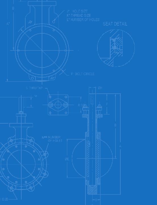
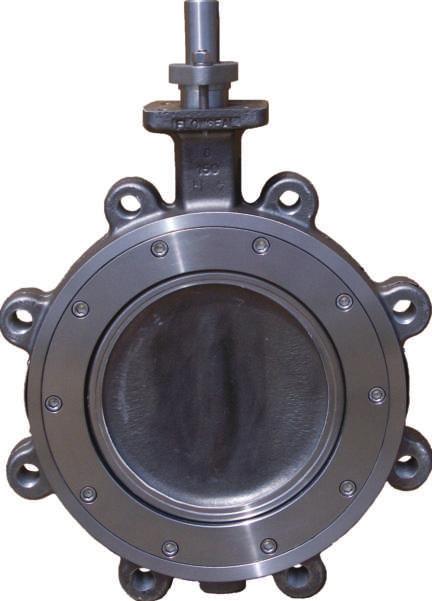
2 FLOWSEAL Flowseal high performance butterfly valves are available in sizes from 2" - 48" in ASME pressure classes 150, 300, and 600 and are available with a diverse range of actuation options. F lowseal is a leading provider of soft seat, metal seat and firesafe high performance butterfly valves. Our products are manufactured under an ISO 9001 Quality Assurance Program that assures each valve we produce meets or exceeds your exacting application requirements. Additionally, our Design and Manufacturing facility is certified to the Pressure Equipment Directive (PED), and Flowseal valves can be ordered as CE marked (see page 23). Flowseal high performance butterfly valves are a standard in many industries including heating, ventilating and air conditioning, power generation, hydrocarbon processing, water and waste water treatment, and marine and commercial shipbuilding. Our products are also installed in applications as diverse as food and beverage processing, snowmaking and pulp and paper production. Configurations are available for harsh conditions as well as applications requiring nominal pressure and temperature ratings. As part of Crane Valve Group, Flowseal high performance butterfly valves are backed by the resources and experience of one of the world s largest valve producers with a delivery and quality track record that is unparalleled in the industries we serve. High Performance Butterfly Valves Soft Seat Metal Seat Fire-Safe Seat ISO Marine Nuclear Power Electric Actuators On/Off Modulating Pneumatic Actuators Spring-Return Double Acting Vane Actuators Double Acting Failsafe Manual Operators Series W Gear Operators* Levers Typical Applications Hydrocarbon Processing Chemical/Petrochemical Processing Power and Utilities Marine and Commercial Shipbuilding Power and Utilities Pulp and Paper NOTE: In keeping with our policy of continuing improvement, we reserve the right to institute changes in design, material, dimensions, or specifications without notice and without incurring any obligation to make such changes and modifications on product previously or subsequently sold. * For valves supplied with a chainwheel, the positive restraint option is recommended. 2
3 Unique Valve Seat Design Soft Seat Disc Seat O Ring Flowseal is one of the world's leading manufacturers of high performance butterfly valves. Based on many years of research, development and field experience, the Flowseal design is superior to and more versatile than the High Performance Butterfly Valve design offered by other manufacturers. The Flowseal Soft Seat valve prodvides a bi-directional bubble tight shutoff (zero leakage) by the use of a patented seat. This unique seat design creates a self-energized seal in vacuum-to-low pressure applications. Under higher pressure conditions, the seat is also designed to permit, confine and direct movement of the soft seat against the disc edge, up to the full ASME Class 150, 300 and 600 Cold Working Pressures. The Soft Seat is designed for high services with minimal wear and low torque. Seat replacement is a simple operation, requiring no special tools. 3
4 Soft Seat Principle of Seat Sealing DISC OPEN In Figure 1, the disc and seat are not engaged. In this position, the shoulders of the seat are forced against the cavity shoulders by the compression of the o-ring. The seat is recessed inside the seat cavity and acts as a gasket in the anchoring groove area. The seat cavity is sealed from exposure from the process fluid and protects the seat from abrasion and wear. The o-ring, which is completely encapsulated by the seat, is also isolated from exposure to the process fluid. Seat Tongue Cavity Shoulders Seat Shoulders Parallel-Spaced Sidewalls O-Ring Convergent Sidewalls Seat Retainer Ring Seat Tail Anchoring Groove Figure 1 Disc Body DISC CLOSED, Self-Energized Seal In Figure 2, the Flowseal disc and seat are engaged, and the process fluid is under low pressure. The edge of the disc, with a larger diameter than the seat tongue, directs movement of the seat radially outward, causing the seat to compress against the convergent sidewalls of the cavity. The elastomeric o-ring imparts a mechanical pre-load between the disc and seat tongue as it is compressed and flattened by the disc; this is the self-energized mode for sealing at vacuum-to-60 psig. As the seat moves radially outward, the seat shoulders move away from the cavity shoulders and open the cavity to the process media. Figure 2 DISC CLOSED, Pressure-Energized Seal (Seat Upstream) As line pressure increases, the process fluid enters the sidewall area and applies a load against the parallel-spaced sidewall and convergent sidewall of the seat. The seat and cavity design permits the seat to move axially to the downstream sidewall, but confines the movement and directs the movement radially inward towards the disc; the higher the line pressure, the tighter the seal between the disc and seat. Because the o-ring is elastic, it is able to flex and deform under loads and return to original shape after removal of the load; it is the rubber which deforms, not the thermoplastic material. This dynamic seal, patented by Flowseal, is totally unique among high performance butterfly valves. Pressure Figure 3 DISC CLOSED, Pressure-Energized Seal (Seat Downstream) Figure 4 The Flowseal valve is bi-directional (in some instances, modifications may be required to operate this arrangement for dead end service). The cavity and seat sidewalls are symmetrically designed to permit, confine and direct movement of the seat to the disc to dynamically seal with line pressure in the reverse direction. The disc edge is the segment of a sphere, and the seat is angled towards the disc edge to seal with pipeline pressure in either direction. Recommended installation direction is SUS (seat upstream), as in Figure 3. Pressure 4
5 Valve Components Soft Seat KEY Square key valve-to-operator connection provides an externally controlled failure point upon over-torquing. BLOW OUT PROOF SHAFT Solid shaft provides alignment and rigid support for disc. GLAND FLANGE Applies load against packing gland to prevent external leakage. Fully adjustable. PACKING Chevron design TFE prevents external leakage out valve neck to full ANSI hydrostatic shell test pressures (150% of C.W.P.). WEDGE RING Stainless steel band wedged between valve body and retainer ring by set screws to lock seat and retainer ring in position on valve sizes 2" through 30". Socket head cap screws are used on valve sizes 36" and larger. SET SCREWS Cone point screws force wedge ring outward to lock seat retainer in position on valve sizes 2" through 30". Socket head cap screws are used on valve sizes 36" and larger. OVERTRAVEL STOP Prevents disc from rotating into the wrong quadrant. PACKING GLAND Separate part from gland flange, preventing uneven load distribution against packing. BEARINGS Both above and below the disc, bearings are of composite design: PTFE bonded to epoxy-glass filament wound ring. Used to align shaft, with high capacity, low wear, and low friction coefficient. DISC SPACERS Disc is centered by use of thrust spacers around shaft in sizes 2" to 5". Disc position stops or thrust bolt arrangements are used for larger valve sizes. WEDGE PINS Provide positive mechanical attachment of disc to shaft. BODY ANSI B.34 design in either wafer or lug configuration. DISC 360 uninterrupted spherical edge for sealing. Profile is designed for maximum flow and equal percentage control. SOFT-SEAT Patented bi-directional seat with encapsulated elastomeric o-ring core for resiliency. Common seat materials include TFE, RTFE and UHMWPE. RETAINER RING Retains seat in valve. Standard surface finish is 125 to 200 AARH and is compatible with both standard gaskets and spiral wound gasket designs. Outside diameter is recessed within gasket sealing surface to prevent external leakage. End Seal Variation The ASME " through 30" sizes feature a two-piece shaft design. The lower shaft utilizes an end seal in the body to prevent external leakage. The component parts include an end seal, an end cap and end cap bolts. Lower Packing Variation The ASME " through 48"; ASME " through 30"; ASME " through " sizes feature a twopiece shaft design which utilizes a lower packing seal in the valve body to prevent external leakage. The component parts are of the same design used in the packing assembly in the top of the valve body neck. END SEAL END CAP BOLTS PACKING GLAND GLAND FLANGE STUDS & NUTS 5
6 Soft Seat Pressure/Temperature Ratings PRESSURE/TEMPERATURE RATINGS As temperature increases, the pressure retaining capability of materials decreases. The graph below illustrates the pressure/temperature ratings of the Flowseal ASME Class 150, Class 300 and Class 600. The heavy lines define the ratings of the carbon steel and stainless steel valve body (or shell ) in conformance to ASME B.34. The shaded areas define the ratings of the TFE and RTFE Seat materials. Seat ratings are based on differential pressure with the disc in the fully closed position.* Steam Service TFE seated valves are rated for 50 psi saturated steam. Valves with O seat configuration (RTFE seat / AFLAS O ring) are rated to 100 psi steam service. ASME B.34 Body and Flowseal Soft Seat Pressure - Temperature Ratings Temperature - C ANSI 600 CS ASME 600 SS Working Pressure -PSIG F LOW TEMP CS LIMIT RTFE 68.9 ASME 300 CS ASME 300 SS TFE ASME 150 CS ASME 150 SS Working Pressure -BARG Temperature - F *Valves with 3 SS shafts are rated for maximum pressure differentials of 150 psi for Class 150, 300 psi for Class 300, and 600 psi for Class 600. (This does not apply to 2"12" Soft Seat valves.) 6
7 Dimensions Soft Seat WAFER LUG ASME Class 150 VALVE SIZE WAFER LUG WEIGHT (LBS.) A* A** B C D E F G H J* K* L* M** N** P R S WAFER LUG 2" /.500 5/ / " /.500 5/ " / " / " / " " " " oval " oval " oval " oval " thru " thru " " " " "
8 Soft Seat Dimensions ASME Class 300 VALVE SIZE WAFER LUG WEIGHT (LBS.) A* A** B C D E F G H J* K* L* M** N** P R S WAFER LUG 2" /.500 5/ " /.500 3/ " " /.625 3/ / " " / / " " " " " " " " " " ASME Class 600 VALVE SIZE WAFER LUG WEIGHT (LBS.) A* A** B C D E F G H J* K* L* M** N** P R S WAFER LUG 2" /.500 5/ " /.500 3/ " " " " " " " / / NOTES: 1. General a. Standard valves tested to MSS-SP-61. API-598 testing available on request. b. Valves for installation between DIN and JIS flanges available on application. c. Dimensions shown are for reference only. Certified drawings available on application. 2. For 2" through 24" sizes: a. Face-to-face dimensions (C) meet, within specified tolerance, MSS-SP-68 and API-609 requirements. b. Valves are designed for installation between ASME B.5 flanges. 3. For 30" through 48" sizes: a. Valves are designed for installation between ASME B.47 Class A flanges. (Class B on request) 4. For MIL SPEC valves, see Flowseal Marine Product Brochure. 8
9 Unique Valve Seat Design Metal Seat Disc/Nitrided 300 Series Stainless Steel Backup Ring Inconel Seat The Flowseal metal-to-metal seat high performance butterfly valve incorporates an Inconel seat for higher tensile strength, a 300 series stainless steel back-up ring in the seat cavity for axial seat support, and a disc that is case hardened by nitriding. The Inconel seat, by its dynamic and flexible design, applies enough force per linear inch against the disc edge (Rockwell Hardness of C66 to C70) to obtain an optimum sealing characteristic while controlling the loads between the metal surfaces. The Flowseal metal-to-metal seat valve is utilized for temperatures up to 900 F, in compliance with ASME B.34 pressure/temperature specifications. Leakage is rated at Class IV per ASME FCI
10 Metal Seat Principle of Seat Sealing PRINCIPLE OF METAL SEATING Metal-to-metal sealing is accomplished by the line contact between a spherical surface and conical surface. Figure 1 illustrates a typical globe control valve seat and plug. The plug seating surface is the segment of a sphere; when engaged against the seat ring, a line contact seal is achieved. In a metal seat design, it is necessary to apply enough force per linear inch to maintain a tight metal-to-metal contact between the sealing members; however, high linear thrust can cause a collapse of the seating members ( bearing failure ). DISC CLOSED, Self-Energized Seal In Figure 2, the Flowseal disc and seat are engaged, and the process fluid is under low pressure. The spherical edge of the disc, with a larger diameter than the conical seat tongue, imparts a thrust of approximately 600 pounds per linear inch against the seat. The mechanical properties and shape of the Inconel seat allow it to both flex and maintain a constant thrust against the disc. This controlled loading prevents the occurence of bearing failure and reduces the leakage and wear between the components. DISC CLOSED, Pressure-Energized Seal (Seat Upstream) As line pressure increases, the process fluid enters the sidewall area and applies a load against the parallel-spaced sidewall and convergent sidewall of the metal seat. The seat moves towards the downstream sidewall while being supported axially by the support ring, as shown in Figure 3. The cavity shape confines the seat movement and directs the movement radially inward towards the disc; the higher the line pressure, the tighter the line contact between the disc and seat. The Inconel seat, shaped by a special hydroforming process, is able to flex under these loads and return to its original shape after removal of the loads. This dynamic seal, patented by Flowseal, is totally unique among high performance butterfly valves. Seat Tongue Parallel-Spaced Sidewalls Back-up ring Convergent Sidewalls Seat Tail Seat Retainer Ring Gaskets PLUG (Spherical seating surface) Pressure Figure 1 Figure 2 Figure 3 SEAT RING (Conical seating surface) Disc Body DISC CLOSED, Pressure-Energized Seal (Seat Downstream) Figure 4 The Flowseal valve is bi-directional (in some instances, modifications may be required to operate this arrangement for dead end service). The cavity and seat sidewalls are symmetrically designed to permit, confine and direct movement of the seat to the disc to dynamically seal with line pressure in the seat downstream direction, as in Figure 4. Recommended installation direction is SUS (seat upstream), as in Figure 3. The stainless steel back-up ring interacts dynamically with the metal seat for axial support in seat sealing. Additionally, this ring effectively restricts corrosion and particulate build-up in the cavity. Pressure 10
11 Valve Components Metal Seat KEY Square key valve-to-operator connection provides an externally controlled failure point upon over-torquing. SHAFT Solid shaft provides alignment and rigid support for disc. GLAND FLANGE Applies load against packing gland to prevent external leakage. Fully adjustable. PACKING Common materials are TFE for up to 450 F and Graphite for up to 900 F. WEDGE RING Stainless steel band wedged between valve body and retainer ring by set screws to lock seat and retainer ring in position on valve sizes 2" through 30". Socket head cap screws are used on valve sizes 36" and larger. WEDGE PINS Provide positive mechanical attachment of disc to shaft. PACKING GLAND Separate part from gland flange, preventing uneven load distribution against packing. BEARINGS Both above and below the disc, bearings maintain shaft alignment. Common materials include: Glass-backed TFE for up to 450 F. (Not for steam service.) Luberized Bronze for up to 750 F. 300 Series Stainless Steel Nitrided for up to 900 F. DISC SPACERS Disc is centered by use of thrust spacers around shaft in sizes 2" to 5". Disc position stops or thrust bolt arrangements are used for larger sizes. OVERTRAVEL STOP Prevents disc from rotating into wrong quadrant. SET SCREWS Cone point screws force wedge ring outward to lock seat retainer in position on valve sizes 2" through 30" Socket head cap screws are used on valve sizes 36" and larger. BODY ASME B.34 design in either wafer or lug configuration. DISC 360 uninterrupted spherical edge for sealing. Profile is designed for maximum flow and equal percentage control. Disc seating surface is Nitrited for enhanced temperature and abrasion resistance METAL SEAT Patented metal seat with metal back-up ring. RETAINER RING Retains seat in valve. Standard surface finish is 125 to 250 AARH and is compatible with both standard gaskets and spiral wound gasket designs. Outside diameter is recessed within gasket sealing surface to prevent external leakage. End Seal Variation The ASME " through 24" sizes feature a two-piece shaft design. The lower shaft utilizes an end seal in the body to prevent external leakage. The component parts include an end seal, an end cap and end cap bolts. END SEAL END CAP BOLTS Lower Packing Variation The ASME " through 48"; ASME " through 30"; ASME " through " sizes feature a two-piece shaft design which utilizes a lower packing seal in the valve body to prevent external leakage. The component parts are of the same design used in the packing assembly in the top of the valve body neck. PACKING GLAND GLAND FLANGE STUDS & NUTS 11
12 Metal Seat Pressure/Temperature Ratings PRESSURE/TEMPERATURE RATINGS As temperature increases, the pressure retaining capability of materials decreases. The graph below illustrates the pressure/temperature ratings of the Flowseal ASME Class 150, Class 300 and Class 600. The heavy lines define the ratings of the carbon steel and stainless steel valve body (or shell ) in conformance to ASME B.34. The shaded areas define the ratings of the metal seat. Seat ratings are based on differential pressure with the disc in the fully closed position. ASME B.34 Body and Flowseal Metal Seat Pressure - Temperature Ratings Temperature - C ASME 600 CS ASME 600 SS Working Pressure -PSIG F LOW TEMP CS LIMIT ASME 300 CS ASME 300 SS ASME 150 CS ASME 150 SS METAL METAL Temperature - F F HI-TEMP CS LIMIT F METAL SEAT TEMP LIMIT Working Pressure -BARG 12
13 Dimensions Metal Seat WAFER LUG ASME Class 150 VALVE SIZE WAFER LUG WEIGHT (LBS.) A* A** B C D E F G H J* K* L* M** N** P R S WAFER LUG 2" / " / " " " " " " " oval " oval " oval " oval " thru " " " " " "
14 Metal Seat Dimensions ASME Class 300 VALVE SIZE WAFER LUG WEIGHT (LBS.) A* A** B C D E F G H J* K* L* M** N** P R S WAFER LUG 2" /.500 5/ / " /.500 3/ / " " /.625 3/ / " " / / / " " " " " " " " " " ASME Class 600 VALVE SIZE WAFER LUG A* A** B C D E F G H J* K* L* M** N** P R S WAFER LUG 2" /.500 5/ " / " " " " " " " / / NOTES: 1. General a. Standard valves tested to MSS-SP-61 and ASME/FCI 70-2, Class IV. API-598 testing available on request. b. Valves for installation between DIN and JIS flanges available on application. c. Dimensions shown are for reference only. Certified drawings available on application. 2. For 2" through 24" sizes: a. Face-to-face dimensions (C) meet, within specified tolerance, MSS-SP-68 and API-609 requirements. b. Valves are designed for installation between ASME B.5 flanges. 3. For 30" through 48" sizes: a. Valves are designed for installation between MSS-SP-44 flanges. 4. For MIL SPEC valves, see Flowseal Marine Product Brochure. 5. For ISO valves see, Flowseal ISO Product Brochure. 14
15 Materials and Specifications Metal Seat STANDARD MATERIALS OF CONSTRUCTION Carbon Steel Construction 20 F to 450 F 451 F to 750 F 751 F to 800 F COMPONENTS 171MTG CONSTRUCTION 171MGB CONSTRUCTION 172MGS CONSTRUCTION BODY Carbon Steel Carbon Steel Carbon Steel A2 Gr WCB, or A105 A2 Gr WCB, or A105 A2 Gr WCB, or A105 DISC 3 Stainless Steel 3 Stainless Steel 3 Stainless Steel A351 CF8M, or A182 F3 A351 CF8M, or A182 F3 A351 CF8M, or A182 F3 Nitrided Nitrided Nitrided SHAFT & PINS 17-4 PH Stainless Steel 17-4 PH Stainless Steel 17-4 PH Stainless Steel A564 Gr 630 A564 Gr 630 A564 Gr 630 SEAT Inconel Inconel Inconel PACKING PTFE Graphite Graphite BEARINGS Glass-Backed PTFE Bronze 3 Stainless Steel Nitrided Stainless Steel Construction 100 F to 450 F 451 F to 750 F 751 F to 900 F COMPONENTS 271MTG CONSTRUCTION 271MGB CONSTRUCTION 272MGS CONSTRUCTION BODY 3 Stainless Steel 3 Stainless Steel 3 Stainless Steel A351 CF8M, or A182 F3 A351 CF8M, or A182 F3 A351 CF8M, or A182 F3 DISC 3 Stainless Steel 3 Stainless Steel 3 Stainless Steel A351 CF8M, or A182 F3 A351 CF8M, or A182 F3 A351 CF8M, or A182 F3 Nitrided Nitrided Nitrided SHAFT & PINS 17-4 PH Stainless Steel 17-4 PH Stainless Steel 3 Stainless Steel* A564 Gr 630 A564 Gr 630 A479 Gr 3 SEAT Inconel Inconel Inconel PACKING PTFE Graphite Graphite BEARINGS Glass-Backed PTFE Bronze 3 Stainless Steel Nitrided * Metal Seat Valves with 3 SS Shafts are rated for maximum pressure differentials of 150 psi for Class 150, 300 psi for Class 300 and 600 psi for Class 600. Monel, Nitronic 50 and Inconel 718 or X750 shafts may be substituted for higher pressure differentials at elevated temperatures. Consult factory for additional information. 15
16 Fire Flow Unique Valve Seat Design Disc Metal Seat Soft Seat O Ring Metal Seat Gasket The Flowseal Fire-Flow high performance butterfly valve (HPBFV) is a fire-safe, soft seat quarter-turn valve. The Fire-Flow design incorporates two patented seats which function together to seal off pipeline flow. In normal operation, the soft seat provides a bi-directional bubble tight shutoff (zero leakage); the metal seat provides bidirectional shutoff in the event of a fire, in conformance to industry fire-safe requirements. With little or no pressure, the Fire-Flow seat creates a self-energized seal against the disc. Higher line pressures act on the geometry of both seats to dynamically load them against the disc, creating higher sealing forces in either direction. The Fire-Flow metal seat is made of Inconel material which is shaped by a proprietary hydroforming process into its unique, patented design. Stainless steel outer bearings are included for post-fire disc and shaft alignment. Fireproof packing is used to prevent external shaft leakage.
17 Principle of Seat Sealing Fire Flow DISC OPEN, Normal Operation In Figure 1, the disc and seat assembly are not engaged. In this position, the metal seat acts to keep the soft seat inside the seat cavity while the soft seat shoulders seal the cavity from exposure to the process fluid. (The o-ring is under tension and imparts a load against the soft seat.) The soft seat is protected from abrasion and wear because it is recessed inside the seat cavity area. The o-ring is isolated from exposure to the fluid because it is completely encapsulated by the seat tails which act as a (soft) gasket in the anchoring groove area. The metal seat gaskets add further high temperature protection past the anchoring grooves. DISC CLOSED, Normal Operation In Figure 2, the disc and seat assembly are engaged; both the metal seat and the soft seat are in contact with the disc. Under little to no pressure conditions, both seats are self-energized. The disc edge, with a larger diameter than the seat tongues, moves the seats radially outward; the metal seat shape, with a mechanical and dynamic flexibility, is designed to be hoop-loaded and impart a spring force against the disc, while the soft seat o-ring is stretched and flattened (without deformation of the material) and imparts a mechanical pre-load against the disc. With increased line pressure, the process fluid enters the cavity sidewall area and applies loads against the seat sidewalls. The cavity design allows the seats to move toward the downstream sidewalls, but confines and directs the movement radially inward towards the disc; the higher the pressure the tighter the seal. The symmetrical shape and angle of the cavity permit the seal to be bi-directional. DISC CLOSED, After Fire (Seat Upstream) After a fire, with partial or complete destruction of the soft seat, the metal seat maintains metal-to-metal contact with the disc and restricts leakage of the process fluid in conformance to industry fire-safe requirements. With little or no line pressure, the spring force and hoop load of the metal seat maintain a line contact seal against the disc edge. Under higher pressures, the process fluid enters the cavity sidewall areas and applies loads against the seat sidewalls (Figure 3). The geometry of the metal seat permits the seat to move axially, but directs the movement radially inward toward the disc; The higher the pressure, the tighter the line contact seal. Graphite gaskets, on both sides of the metal seat tail, seal the anchoring groove and prevent leakage of the process fluid. Soft Seat Tongue Metal Seat Tongue Seat Shoulders Parallel-Spaced Sidewalls O-Ring Convergent Sidewalls Seat Retainer Ring Soft Seat Tail Anchoring Groove Metal Seat gaskets Pressure Figure 1 Disc Body Figure 2 Figure 3 DISC CLOSED, After Fire (Seat Downstream) The Flowseal Fire-Flow valve is bi-directional, however, modifications are required to operate for bi-directional dead end service. The angle and shape of the cavity and metal seat maintains metal-to-metal contact in the event of partial or complete soft seat destruction with line pressure in the reverse direction (Figure 4). While the preferred flow direction is seat upstream (SUS), the bidirectional seat design is both self-energized and pressure-energized if the flow direction is seat downstream (SDS). Figure 4 Pressure 17
18 Fire Flow Valve Components KEY Square key valve-to-operator connection provides an externally controlled failure point upon over-torquing. SHAFT Solid shaft provides alignment and rigid support for disc. GLAND FLANGE Applies load against packing gland to prevent external leakage. Fully adjustable. PACKING Common material is graphite PACKING GLAND Separate part from gland flange, preventing uneven load distribution against packing. OUTER BEARINGS Stainless steel back-up bearings maintain shaft alignment after a fire. (Both above and below disc.) DISC SPACERS Disc is centered by use of thrust spacers around shaft in sizes 2" to 5". Disc position stops or thrust bolt arrangements are used for larger valve sizes. RETAINER RING Retains seat in valve. Standard surface finish is 125 to 200 AARH and is compatible with both standard gaskets and spiral wound gasket designs. Outside diameter is recessed within gasket sealing surface to prevent external leakage. OVERTRAVEL STOP Prevents disc from rotating into wrong quadrant. INNER BEARINGS Both above and below the disc, bearings are of composite design: TFE bonded to epoxy-glass filament wound ring. Used to align shaft, with high load capacity, low wear and low friction coefficient. WEDGE PINS Provide positive mechanical attachment of disc to shaft. BODY ASME B.34 design in either wafer or lug configuration. DISC Fire-Flow disc is electroless nickel plated for enhanced temperature and abrasion resistance. SET SCREWS Cone point screws force wedge ring outward to lock seat retainer in position on valve sizes 2" through 30". Socket head cap screws are used on valve sizes 36" and larger. WEDGE RING Stainless steel band wedged between valve body and retainer ring by set screws to lock seat and retainer ring in position on valve sizes 2" through 30". Socket head cap screws are used on valve sizes 36" and larger. End Seal Variation The ASME " through 24" sizes feature a two-piece shaft design. The lower shaft utilizes an end seal in the body to prevent external leakage. The component parts include an end seal, an end cap and end cap bolts. INNER BEARING OUTER BEARING END SEAL END CAP BOLTS FIREFLOW SEAT Patented bi-directional soft seat design for zero-leakage in normal operation and a metal-to-metal seal after fire, meeting or exceeding industry fire-safe specifications. Lower Packing Variation The ASME " through 48"; ASME " through 30"; ASME " through " sizes feature a two-piece shaft design which utilizes a lower packing seal in the valve body to prevent external leakage. The component parts are of the same design used in the packing assembly in the top of the valve body neck. INNER BEARING OUTER BEARING PACKING GLAND GLAND FLANGE STUDS & NUTS 18
19 Pressure/Temperature Ratings Fire Flow PRESSURE/TEMPERATURE RATINGS As temperature increases, the pressure retaining capability of materials decreases. The graph below illustrates the pressure/temperature ratings of the Flowseal ASME Class 150, Class 300 and Class 600. The heavy lines define the ratings of the carbon steel and stainless steel valve body (or shell ) in conformance to ASME B.34. The shaded areas define the ratings of the soft seat. Seat ratings are based on differential pressure with the disc in the fully closed position. ASME B.34 Body and Flowseal Soft Seat Pressure - Temperature Ratings Temperature - C ANSI 600 CS ASME 600 SS Working Pressure -PSIG F LOW TEMP CS LIMIT RTFE 68.9 ASME 300 CS ASME 300 SS TFE ASME 150 CS ASME 150 SS Temperature - F Working Pressure -BARG 19
20 Fire Flow Dimensions WAFER LUG ASME Class 150 VALVE WAFER LUG WEIGHT (LBS.) SIZE A* A** B C D E F G H J* K* L* M** N** P R S WAFER LUG 2" / " / " " " " " " " oval " oval " oval " oval " thru " " thru " " " "
21 Dimensions Fire Flow ASME Class 300 WAFER LUG WEIGHT (LBS.) VALVE SIZE A* A** B C D E F G H J* K* L* M** N** P R S WAFER LUG 2" /.500 5/ " / " " /.625 3/ / " " / " " " " " " " " " " ASME Class 600 VALVE SIZE WAFER LUG WEIGHT (LBS.) A* A** B C D E F G H J* K* L* M** N** P R S WAFER LUG 2" /.500 5/ " / " " " " " " NOTES: 1. General a. Standard valves tested to MSS-SP-61. API-598 testing available on request. b. Valves for installation between DIN and JIS flanges available on application. c. Dimensions shown are for reference only. Certified drawings available on application. 2. For 2" through 24" sizes: a. Face-to-face dimensions (C) meet, within specified tolerance, MSS-SP-68 and API-609 requirements. b. Valves are designed for installation between ASME B.5 flanges. 3. For 30" through 48" sizes: a. Valves are designed for installation between MSS-SP-44 and ASME B.47 flanges. 4. For MIL SPEC valves, see Flowseal Marine Product Brochure. 5. For ISO valves, see Flowseal ISO Product Brochure. 21
22 Flowseal Valve Flow Coefficients C V FACTORS C v (Coefficient of Volume) is the number of U.S. gallons per minute of water required to pass through a valve with a pressure drop of 1 psi. The chart below records this C v factor for the Flowseal valve classes and sizes at ten degree increments between open and closed. The values shown are for the valve installed in the seat upstream ( SUS ) position. Degree Open % Full C v 1.5% 6% 14% 25.2% 38% 55% 75% 97% 100% 2" /2" " /2" " " " " " " " " " " " " " " " C f FACTORS The critical flow factor, C f, expresses the valve pressure recovery ratio. It is equivalent to F L in ISA nomenclature. DISC DEGREE OPENING SEAT UPSTREAM SEAT DOWNSTREAM
23 Ordering Information Flowseal 1. Size Code 2" /2" 025 3" /2" 035 4" 04 to 48" Body Class Code 150 PSI Max. Diff. Pressure 0 ASME ASME ASME Body Type Code Wafer W Lugged L Lugged DDES D 4. Shaft Design Code Straight A Class 150 2" - 12" Class " - 48" Class 300 2" - 12" & 30" Class 600 2" - 8" Balanced C Class " - 30" Derated** 36" - 48" Class " - 24" Class " - " 5. Body Material Code Carbon Steel 1 3 SS 2 Monel 3 Alloy 20 4 Alum Bronze MIL-B Alum Bronze B148 ASTM C958 8 Hastelloy C H Special X Note 1: Use of 3 SS shaft may lower shutoff differentials. Consult factory. Note 2: DDES = Double Dead End Service 6. Disc Material Code Alum Bronze/ENP B148 C SS 2 Monel 3 Alloy 20 4 Alum Bronze MIL-B SS Nitrided 7 Alum Bronze B148 ASTM C SS/ENP 9 Hastelloy C H Hastelloy C/ENP J Special X 7. Shaft Material Code 17-4PH SS 1 3 SS (See Note 1) 2 Monel 3 Alloy 20 4 Inconel 718/750 6 Ferralium A479 7 Nitronic 50 0 Hastelloy C H Special X 8. Seat Material / O-Ring Code TFE / Viton T RTFE / Silicon R RTFE / AFLAS O Polyethylene (UHMWPE) / Viton L Fire-Flow (TFE & Metal) / Viton F Fire-Flow (RTFE & Metal) / B Viton Inconel M 300 SS S Fire-Flow (TFE & Monel) / Viton C Fire-Flow (RTFE & Monel) / J Silicon Fire-Flow (TFE & Hastelloy C) / H Viton Fire-Flow (RTFE & Hastelloy C) / K Silicon Special X 9. Packing Material Code TFE T Graphite G Fire-Flow F Special X 10. Bearing Material Code Glass Backed TFE G 3 SS Backed TFE H Fire-Flow (Garfil & 3 SS) F Stainless Steel Nitrided S Bronze B Monel K Hastelloy C Backed TFE J Special X 11. Actuator Type Code Bare Shaft B Ratchet Handle H Ratchet Handle w/lock L Throttle T Worm Gear 3 Pneumatic Double Acting 4 Pneumatic SR Fail Close 5 Pneumatic SR Fail Open 6 Hydraulic 7 Electric 8 Other X 12. Special Feature Code None O Oxygen Service A Bi-directional B Chlorine Service C Dead-end Service (DDES) D CE Marked P CE Marked for DDES E Flat Face F Mil-V M NACE Construction N 60 to 125 AARH Facing S Vacuum Service V Special Feature X Further Description Required 13. Series *Factory Assigned Example: 12-1WA - 171MTG " Wafer Style Class 150 Carbon Body, Straight 17-4 Ph SS Stem, 3 SS Nitrided Disc, Inconel Seat, TFE Pkg, Glass Backed TFE Bearings, Gear Operated FLOWSEAL ACTUATOR OPTIONS: Lever: Not recommended for Metal Seat High Performance Butterfly Valve Worm Gear Operators: Five types available: Optional: High temperature service Chain wheel Buried service Output shaft extension Submersible service Input shaft extension Marine service Military special operator Standard aluminum handwheel AWWA special operator Hydraulic Actuator: Pneumatic Actuators: Electric Actuators: Customer specified hydraulic actuator Crane Revo spring return pneumatic actuator Crane Revo double acting pneumatic actuator Customer specified pneumatic actuator Series electric actuator Customer specified electric actuator 23
24 Engineering Data Valve Torque Tables DESCRIPTION OF TORQUE What is TORQUE? Torque is any (man or machine) effort which tends to cause rotation or turning. In engineering terms, torque is defined as force acting at some distance from the center of rotation. More correctly: Torque equals force times the perpendicular distance from the center of rotation. The perpendicular distance from the center of turning is sometimes called a "moment arm". Torque is measured in units of distance and force; for example: inch pounds, or foot pounds. The equation for torque is: T = F x A (Torque equals Force times Moment Arm) HIGH-PERFORMANCE BUTTERFLY VALVE TORQUE The High-Performance Butterfly Valve (HPBFV) is a Quarter-Turn valve design; that is, it rotates one-quarter of a full 360 turn to move from open to closed or from closed to open. Seating torque is created by contact between the disc and seat as the disc rotates closed. Unseating torque is created by the disc breaking away from the seat as the disc rotates open. The Flowseal seat creates a seal at no-to-low pressure conditions by means of a mechanical "preload" between the disc and the seat; this pre-loading allows the seat seal to be self-energized. When line pressure is introduced, the Flowseal seat is designed to use the line pressure to create an even tighter seal between the disc and the seal (the higher the pressure, the tighter the seal); this dynamic sealing causes the Flowseal seat to be pressure energized. The valve seating and unseating torque increases as the seat seal moves from the self-energized mode to the pressure-energized mode. (Refer to the valve torque tables for the appropriate torque.) A difference in torque exists between the seat upstream (SUS) and seat downstream (SDS) positions because of the disc and shaft design. All Flowseal HPBFVs have both off-set discs and eccentric shafts. The off-set is applicable to the disc edge seating surface relative to the shaft center line. By off-setting the seating surface from the rotational center line, a contact with the seat is possible throughout the 360 circumference. The shaft is eccentric in the body by ins. and this enhances seat life by imparting a camming action to the disc as it rotates both in and out of the seat. Seat wear points are eliminated at the top and bottom of the disc and operating torque is reduced. Travel Arc of Spherical Diameter of Disc about Shaft & Pivot CL Spherical Diameter of Disc Shown in Closed Position Shaft & Pivot CL CL of Disc (Closed) Spherical Diameter of Disc Shown in Open Position Rotation to Open Shaft & Pivot CL CL of Disc (Open) FLOWSEAL HPBFV ECCENTRIC SHAFT DESIGN In the SUS position (preferred pipeline flow direction), the line pressure tends to assist in opening the valve disc. In the SDS position, the line pressure tends to assist in keeping the valve disc closed; also, line pressure acting on the surface of the disc creates more mechanical pre-load between the disc and seat. Therefore, SDS torque values are higher than SUS values. 24
25 Valve Torque Tables Engineering Data ASME Class 150 I. SEATING and UNSEATING TORQUE VALUES (All Torques are in Inch Pounds) SOFT SEAT VALVE SEAT SEAT SIZE UPSTREAM DOWNSTREAM (SUS) (SDS) PSIG 285 PSIG PSIG 285 PSIG 3" " " " " " " " " " " " " " " VALVE SIZE FIRE-FLOW SEAT SEAT SEAT UPSTREAM DOWNSTREAM (SUS) (SDS) PSIG 285 PSIG PSIG 285 PSIG 3" " " " " " " " " " " " " C.F. C.F. C.F. C.F. 42" C.F. C.F. C.F. C.F. METAL SEAT VALVE SEAT SEAT SIZE UPSTREAM DOWNSTREAM (SUS) (SDS) PSIG 285 PSIG PSIG 285 PSIG 3" " " " " " CONSULT CONSULT 14" FACTORY FACTORY " " " " " " C.F. C.F. 42" C.F. C.F. Torques shown are for on/off applications and include sizing margins appropriate to normal liquid and gas applications. For severe services, or unusual fluids or slurries, consult factory. II. HYDRODYNAMIC TORQUE VALUES The equal percentage flow characteristics of the Flowseal HPBFV makes it well-suited for proportional control applications. Hydrodynamic valve torques develop as a result of the pipeline process conditions (media, velocity, pressure, temperature, and turbulance) and the shape and degree position of the valve disc. Under certain conditions, hydrodynamic torques can meet or exceed seating and unseating torques; when selecting actuators for throttling services, hydrodynamic torque must be considered to help ensure correct selection of actuation. The chart below provides a C t (Torque Coefficient) factor to aid in actuator sizing. The C t factors are based on water at ambient temperature, and do not take into account other factors such as: cavitation, flashing, noise, vibration, etc.. These considerations should be addressed prior to hydrodynamic torque sizing. The equation for hydrodynamic torque is: Td = C t x P P = Pressure Drop in PSIG C t = Torque Coefficient Factor Td = Dynamic Torque in Inch Pounds VALVE SIZE Ct = TORQUE COEFFICIENT FACTORS 3" " " " " " " " " " " "
26 Engineering Data ASME Class 300 I. SEATING and UNSEATING TORQUE VALUES (All Torques are in Inch Pounds) VALVE SIZE SOFT SEAT Valve Torque Tables psig 285 psig 400 psig 500 psig 600 psig 700 psig psig 285 psig 400 psig 500 psig 600 psig 700 psig 3" " " " " " " " " " " " VALVE SIZE SEAT UPSTREAM (SUS) SEAT UPSTREAM (SUS) FIRE-FLOW SEAT SEAT DOWNSTREAM (SDS) SEAT DOWNSTREAM (SDS) psig 285 psig 400 psig 500 psig 600 psig 700 psig psig 285 psig 400 psig 500 psig 600 psig 700 psig 3" " " " " " " " " " " " II. HYDRODYNAMIC TORQUE VALUES METAL SEAT VALVE SIZE SEAT UPSTREAM (SUS) SEAT DOWNSTREAM (SDS) psig 285 psig 400 psig 500 psig 600 psig 700 psig psig 285 psig 400 psig 500 psig 600 psig 700 psig 3" " " " " " CONSULT CONSULT 14" " FACTORY FACTORY 18" " " " Torques shown are for on/off applications and include sizing margins appropriate to normal liquid and gas applications. For severe services, or unusual fluids or slurries, consult factory. The chart below provides a C t (Torque Coefficient) factor to aim in actuator sizing. The C t factors are based on water at ambient temperature, and do not take in to account other factors such as: cavitation, flashing, noise, vibration, ect. These considerations should be addressed prior to hydrodynamic torque sizing. P = Pressure Drop in PSIG Td = C t x P C t = Torque Coefficient Factor The equation for hydrodynamic torque is: Td = Dynamic Torque in Inch Pounds VALVE SIZE Disc Position in Degrees Open Ct = TORQUE COEFFICIENT FACTORS 3" " " " " " " " " " " "
27 Valve Torque Tables Engineering Data ASME Class 600 I. SEATING and UNSEATING TORQUE VALUES (All Torques are in Inch Pounds) SOFT SEAT FIRE-FLOW SEAT TORQUES : Consult Factory METAL SEAT TORQUES : Consult Factory II. HYDRODYNAMIC TORQUE VALUES : Consult Factory MATERIAL DESCRIPTIONS : SEAT UPSTREAM (SUS) psig 500 psig 800 psig 1000 psig 1200 psig 1480 psig 3" " " " " " SOFT SEAT SEAT DOWNSTREAM (SDS) psig 500 psig 800 psig 1000 psig 1200 psig 1480 psig 3" " " " " " Torques shown are for on/off applications and include sizing margins appropriate to normal liquid and gas applications. For severe services, or unusual fluids or slurries, consult factory. MATERIAL FORM DESCRIPTION GENERIC NAME SPECIFICATION GRADE CONDITIONS / COMMENTS CASTING A2 WCB A351 CF8M CARBON STEEL STAINLESS STEEL 3 ASTM A 2 ASTM A 351 WCB CF8M NORMALIZE & TEMPER SOLUTION ANNEAL A351 CN7M A352 LCB ALLOY 20 CARBON STEEL TO -50F ASTM A 351 ASTM A 352 CN7M LCB SOLUTION ANNEAL QUENCH & TEMPER BARSTOCK MIL-B QQ-N-288 NITR 50 ALUMINUM BRONZE MONEL NITRONIC 50 MIL-B-24480A (SH) QQ-N-288 / AMO 3 ASTM A COM P. A XM A H1075 STAINLESS STEEL PH ASTM A 479 ASTM A H H1150 B473 20CB QQ-N PH ALLOY 20 MONEL ASTM A 564 ASTM B 473 QQ-N-2810 /AMO CLASS A - FORM 1 H ANNEAL INC 718 C.S. INCONEL 718 CARBON STEEL ASTM A 637 AS AVAILABLE 718 VARIOUS - LOW C (1018) NON-PRESS. PARTS BOLTING 18-8 S.S. A A193-B8M STAINLESS STEEL ALLOY STEEL STAINLESS STEEL 3 AS AVAILABLE ASTM A 193 ASTM A 193 VARIOUS B7 B8M 300 SERIES (304) NON-PRESS. PARTS - - ALY STL 18-8 S.S. ALLOY STEEL STAINLESS STEEL SAE BRACKET & ACCESSORY BOLTING 300 SERIES STAINLESS STEEL 27
28 Engineering Data Body & Components Press./Temp Ratings BODY RATING The charts below reflect the pressure/temperature ratings for carbon steel and stainless steel valves, in accordance with ASME B.34. The hydrostatic shell test is performed on the body at 150% of the cold working pressure (C.W.P. is defined as the pressure rating between -20 to 100 F) and the hydrostatic seat test is performed on the disc and seat at 110% of the cold working pressure. Maximum Non-Shock F Working PressurePSI Carbon Steel 3SS ASME Class HYDROSTATIC SHELL TEST HYDROSTATIC SEAT TEST to Maximum Non-Shock C Working PressureBars Carbon Steel 3SS ASME Class HYDROSTATIC SHELL TEST HYDROSTATIC SEAT TEST to COMPONENTS RATING The chart at right reflects the maximum temperature ratings for individual components of the Flowseal HPBFV. Special care should be taken when specifying component materials for valves at elevated temperatures, especially metal seat valves. Consult factory if additional information is required regarding the suitability of components for specific pressure/ temperature applications. Description & Material Temperature F C Seat Seal (Soft Seated) TFE -100 to to 204 RTFE -100 to to 260 UHMWPE -100 to to 93 Seat Seal (Fire-Flow) TFE/Inconel -100 to to 204 RTFE/Inconel -100 to to 260 Seat Seal (Metal Seats) Inconel to to Stainless Steel -100 to to 538 Seat O-Ring Silicone (Standard with RTFE) -100 to to 260 Viton (Standard with TFE) -50 to to 204 Stem Packing TFE -100 to to 260 Graphite -100 to to 621 Shaft 17-4PH H to to PH H1150M -100 to to Stainless Steel -100 to to 621 K-Monel to to 621 Inconel to to 621 Bearings TFE/Fiberglass Composite -100 to to 260 RTFE/3 Stainless Steel -100 to to 260 Bronze -100 to to 339 Steel -100 to to Stainless Steel -100 to to 538 Disc Treatment Electroless Nickel Plating -100 to to 399 Stellite -100 to to 621 Malcomizing -100 to to
29 Valve Mounting Pad Dimensions Engineering Data J D R (KEY SIZE) F G E Q TAP (TYP) V S (STUD) A C T H L P K M N U B LC of BODY SIZE CLASS SERIES A B C D E F G H J K L M N P Q R S T U V J J J J J J J J J J J J J J J J J J J J J J H J J H x x x x x x x x x x x x x x /8-1 /4 x / /8-3 /8 x / /8-3 /8 x / /8-3 /8 x / /8-3 /8 x / /8-3 /8 x / /8-3 /8 x / /8-3 /8 x / / /2 x / /8-3 /8 x / / /2 x / x
30 Engineering Data Installation Instructions VALVE DESCRIPTION 1. The Flowseal High Performance Butterfly Valve is available in two body styles: Wafer (flangeless) and Lug (single flange). VALVE DESIGN 1. The Flowseal High Performance Butterfly Valve features a double offset (or, double eccentric) shaft design to minimize seat abrasion and lower torque. This double offset design allows the disc to lift off and ìcamîaway from the seat as it rotates open. 2. The Flowseal valve always rotates clockwise to close (when viewed from above) and counterclockwise to open. 3. The valve body has an overtravel stop which prevents the disc from over rotating into the wrong quadrant. This stop is not to be used as a disc position stop; if the disc contacts the overtravel stop, this means it has rotated beyond the seat. 4. The Flowseal valve is bi-directional, but the preferred installation position is with the seat in the upstream position (SUS). Note the arrow on the metal tag attached to the valve body. SAFETY PRECAUTIONS Be sure the line is depressurized and drained. Be sure of the pipeline media. Proper care should be taken for protection against toxic and/or flammable fluids. Never install the valve without an operator (manual or automatic) already attached to the valve shaft. Never remove the operator from the valve while the valve is in the pipeline under pressure. Always be sure that the disc is in the full-closed position before installing the valve. Take care in handling the valve; if you treat it like a machine, it will operate like a machine...if you treat it like a piece of pipe, it may work like a piece of pipe. FLANGE COMPATIBILITY The Flowseal valve is designed to fit between flanges as follows: ASME Class 15 2" to 24" MSS SP-44 Class " to 48" ASME Class 300 2" to 24" MSS SP-44 Class " ASME Class 600 2" to " GASKET COMPATIBILITY The Flowseal valve is designed to accomodate the use of standard fiber gaskets (such as non-asbestos, flexible graphite, asbestos or equivalent gasket materials) of 1/" or less, meeting the dimensional requirements of ASME B Thick elastomeric gaskets are not recommended. Metallic wound (Flexitallic) gaskets may also be used. PIPE SCHEDULE COMPATIBILITY The Flowseal valve is designed to allow the disc edge to rotate into the open position without interference with the pipeline I.D. in the following pipe schedules: SIZE ASME 150 ASME 300 ASME 600 2" 12" SCH 80 SCH 80 SCH " 24" SCH 40 SCH 80 SCH " SCH 30 SCH 80 36" 42" STD WT 48" XS PRODUCT IDENTIFICATION 1. Every Flowseal valve has a metal identification tag attached to the valve body. Information includes the figure number, the size and pressure class, the materials of construction, and the operating pressures and temperatures. 2. Every Flowseal valve is hydrostatically tested before it is shipped. The metal tag also includes a serial number; this number, unique for each valve, is recorded by the Flowseal Quality Control Department along with the test results and material certification data, for individual traceability and verification of every valve produced. Æ A Unit of Crane Valve Group UNPACKING AND STORAGE INSTRUCTIONS 1. Check the packing list against the valve received to verify that the quantities, sizes and materials are correct. 2. Check to make sure that the valve and operator were not damaged during shipment. 3. If the valve is to be stored before being installed, it should be protected from harsh environmental conditions. 4. Store the valve with the disc in the closed position to protect the sealing edge and the seat. 5. Keep the valve in a clean location, away from dirt, debris and corrosive materials. 6. Keep the valve in a dry area with the flange protectors attached. 7. Keep the valve in a cool location if possible, out of direct sunlight. 30
31 Installation Instructions Engineering Data BOLTING DIMENSIONS LUG BODY HEX HEAD MACHINE BOLTS LUG BODY STUDS & NUTS WAFER BODY STUDS & NUTS F G A* B* C D Flange Body Flange Body Body ASME Class 150 2" 24" MSS SP-44 Class " 48" LUG VALVES WAFER VALVES BOLT ENGAGEMENT IN VALVE* STUDS & NUTS MACHINE BOLTS STUDS & NUTS VALVE SIZE VALVE SERIES THREAD SIZE QTY A LG A QTY B LG B QTY C LG C QTY D LG D QTY F LG F QTY G LG G QTY E LG E 2" J 5 / /2" J 5 / " J " J " J 3 / " J " J " J " J " J " J " J " J J ** " J " 36" 42" 48" H H H H H H H H ** 8** 8** 8** Length of machine bolts based on: 1. Gasket thickness of 0.06 inches. 2. Minimum flange thickness of weld neck flanges per ASME B.5. Every effort is made to provide accurate information, but no liability for claims arising from erroneous data will be accepted by Flowseal. 31
32 Engineering Data Installation Instructions VALVE SIZE VALVE SERIES THREAD SIZE BOLTING DIMENSIONS ASME Class 300 2" 24" MSS SP-44 Class " LUG VALVES WAFER VALVES BOLT ENGAGEMENT IN VALVE* STUDS & NUTS MACHINE BOLTS STUDS & NUTS QTY LENGTH QTY LENGTH QTY LENGTH QTY LENGTH QTY LENGTH QTY LENGTH QTY LENGTH A A B B C C D D F F G G E E 2" J 5 / /2" J 5 / " J " J " J 3 / " J " J " 12" 14" J J H J J H ** 8** H " H ** 5.25 H " H ** 5.50 H " H ** 5.75 H " H ** 6.25 H " H ** 8.00 ASME Class 600 3" 14" LUG VALVES WAFER VALVES BOLT ENGAGEMENT IN VALVE* STUDS & NUTS MACHINE BOLTS STUDS & NUTS VALVE VALVE THREAD QTY LENGTH QTY LENGTH QTY LENGTH QTY LENGTH QTY LENGTH QTY LENGTH QTY LENGTH SIZE SERIES SIZE A A B B C C D D F F G G E E 3" J " J " J " J " H H ** " H H ** " H CF CF H CF CF 8** 6.50 * Bolt lengths A & B are from face of valve body to minimum depth in lug. Flange & gasket thickness must be added to calculate minimum bolt length. ** Special length required for tapped blind holes on either side of the valve shaft at the top and bottom ends of the valve body. 32
33 Installation Instructions Engineering Data PRE INSTALLATION PROCEDURE 1. Remove the protective face covers from the valve. 2. Inspect the valve to be certain the waterway is free from dirt and foreign matter. Be certain the adjoining pipeline is free from any foreign material such as rust and pipe scale or welding slag that could damage the seat and disc sealing surfaces. 3. Actuators should be mounted on the valve prior to installation to facilitate proper alignment of the disc in the valve seat. 4. The valve should be in the closed position. Make sure the open and closed positions of the actuator correspond to the counter-clockwise to open direction of rotation of the valve. VALVE INSTALLATION PROCEDURE The Flowseal High Performance Butterfly Valve can be installed in the pipeline with the shaft in the vertical, horizontal, or other intermediate position. Based on applications experience, however, in media with concentrations of solid or abrasive particles or media subject to solidification buildup, valve performance and service life will be enhanced by mounting the valve with the shaft in the horizontal position. All Flowseal valves are bi-directional (in some instances, modifications may be required to operate this arrangement for dead end service) and can be mounted in the pipeline in either flow direction; however, the preferred flow direction for all seat styles and materials is with the seat retainer ring located upstream (sus) to provide maximum seat protection. 1. For Wafer style (flangeless) valves: a. Loosely install the lower flange bolts to form a cradle between the flanges. See Figure 1. b. Noting the flow direction arrow on the tag, place the valve and flange gaskets between the flanges, making sure the arrow on the tag points in the direction of the flow. c. Install the remaining flange bolts, shifting the valve as necessary to permit the bolts to pass by or through the valve body. Figure 1 5. Cycle the valve to the fully open position, then back to the fully closed position, checking the actuator travel stop settings for proper disc alignment. 6. Check the valve identification tag for valve class, materials, and operating pressure to be sure they are correct for the application. WARNING! Personal injury or property damage may result if the valve is installed where service conditions could exceed the valve ratings. 7. Check the flange bolts or studs on both sides of the valve for proper size, threading, and length. 2. For Lug style (single flange) valves: a. Noting the flow direction arrow on the tag, place the valve between the flanges, making sure the arrow on the tag points in the direction of the flow. b. Install the lower flange bolts loosely, leaving space for the flange gaskets. c. After inserting the flange gaskets, install the remaining bolts. 3. Using the sequence shown in Figure 2, tighten the flange bolts evenly to assure uniform gasket compression. Caution: The Flowseal valve should be centered between the flanges and gaskets to prevent damage to the disc edge and shaft as a result of the disc striking the flange, gasket, or pipe. 4. If an actuator is to be used, air hoses or electricity should be connected to the unit as specified by the actuator manufacturer. 5. The valve is now ready for operation. Remember: Install the valve with the disc in the fullclosed position! Figure
34 Flowseal Typical Specifications TYPICAL SOFT SEAT SPECIFICATION TYPICAL METAL SEAT SPECIFICATION TYPICAL FIRE FLOW SPECIFICATION 1.0 Scope This specification covers the design and testing of high pressure offset seat butterfly valves. 2.0 Applicable Standards The following standards shall apply ASME B.5: Pipe Flanges and Flanged Fittings (24" size and smaller). ASME B.34: ValvesFlanged and Buttwelding End. MSS SP-25: Standard Marking System for Valves, Fittings, Flanges and Unions. MSS SP-61: Pressure Testing of Steel Valves. MSS SP-68: High PressureOffset Seat Butterfly Valves. API 609: Butterfly Valves, Lug-Type and Wafer-Type. PED Pressure Equipment Directive Section H 3.0 Design Requirement 3.1 Valves shall be High Performance Butterfly with offset seat and eccentric shaft. They shall be capable of sealing against full differential pressure in either flow direction. 3.2 Valve seat shall be both self and pressure energized with an elastomeric core. The self energizing member shall be isolated from the line media. 3.3 Valves shall have retained top and bottom low friction bearings. 3.4 Shaft design shall be single or dual piece. 3.5 Retainer rings must be recessed in the body so that the line gasket prevents any potential external leakage. 3.6 Valves shall have internal stop to prevent disc over-travel. 3.7 Valves shall be Flowseal or approved equal. 4.0 Materials 4.1 Valves shall be constructed of new material. 4.2 Carbon steel valves shall be constructed from materials below: BodyASTM A105 or A2 Gr. WCB DiscASTM A182 F3 or A351 Gr. CF8M. 4.3 Stainless steel valves shall be constructed from materials below: BodyASTM A182 Gr. F3 or A351 Gr. CF8M DiscASTM A182 Gr. F3 or A351 Gr. CF8M. 4.4 Shafts shall be ASTM A564 type 630 H 1150 or 3 SS. 5.0 Inspection and Test 5.1 Valves shall be hydrostatically shell tested per ANSI B.34 and MSS SP Valves shall be seat tested per MSS SP- 61. No leakage is permitted for resilient seated valves. 5.3 API 598 testing available upon request. Sample Figure Number 12 1WA 121TTG 30J 1.0 Scope This specification covers the design and testing of high pressure offset seat butterfly valves. 2.0 Applicable Standards The following standards shall apply ASME B.5: Pipe Flanges and Flanged Fittings (24" size and smaller). ASME B.34: ValvesFlanged and Buttwelding End. MSS SP-25: Standard Marking System for Valves, Fittings, Flanges and Unions. ASME/FCI 70-2: Control Valve Seat Leakage MSS SP-68: High PressureOffset Seat Butterfly Valves API 609: Butterfly Valves, Lug-Type and Wafer-Type. PED Pressure Equipment Directive Section H 3.0 Design Requirement 3.1 Valves shall be High Performance Butterfly with offset seat and eccentric shaft. They shall be capable of Class IV sealing in either flow direction. 3.2 Valve seat shall be both self and pressure energized. 3.3 Valves shall have retained top and bottom bearings. 3.4 Shaft design shall be single or dual piece. 3.5 Retainer rings must be recessed in the body so that the line gasket prevents any potential external leakage. 3.6 Valves shall have internal stop to prevent disc over-travel. 3.7 Valves shall be Flowseal or approved equal. 4.0 Materials 4.1 Valves shall be constructed of new material. 4.2 Carbon steel valves shall be constructed from materials below: BodyASTM A105 or A2 Gr. WCB DiscASTM A182 F3 or A351 Gr. CF8M. 4.3 Stainless steel valves shall be constructed from materials below: BodyASTM A182 Gr. F3 or A351 Gr. CF8M DiscASTM A182 Gr. F3 or A351 Gr. CF8M. 4.4 Shafts shall be ASTM A564 type 630 H 1150, or 3 SS. 5.0 Inspection and Test 5.1 Valves shall be hydrostatically shell tested per ANSI B.34 and MSS SP Valves shall be seat tested per ANSI/FCI 702, Class IV. Sample Figure Number 12 1WA 171MTG 30J 1.0 Scope This specification covers the design and testing of high pressure offset seat butterfly valves. 2.0 Applicable Standards The following standards shall apply ASME B.5: Pipe Flanges and Flanged Fittings (24" size and smaller). ASME B.34: ValvesFlanged and Buttwelding End. MSS SP-25: Standard Marking System for Valves, Fittings, Flanges and Unions. MSS SP-61: Pressure Testing of Steel Valves. MSS SP-68: High PressureOffset Seat Butterfly Valves. API 609: Butterfly Valves, Lug-Type and Wafer-Type. API 607: Fire Test for Soft-Seated Quarter Turn Valves. PED Pressure Equipment Directive Section H 3.0 Design Requirement 3.1 Valves shall be High Performance Butterfly with offset seat and eccentric shaft. They shall be capable of sealing against full differential pressure in either flow direction. 3.2 Valve seat shall be both self and pressure energized with an elastomeric core. The self energizing member shall be isolated from the line media. 3.3 Valves shall have retained top and bottom low friction bearings. 3.4 Shaft design shall be single or dual piece. 3.5 Retainer rings must be recessed in the body so that the line gasket prevents any potential external leakage. 3.6 Valves shall have internal stop to prevent disc over-travel. 3.7 Valves shall be Flowseal or approved equal. 4.0 Materials 4.1 Valves shall be constructed of new material. 4.2 Carbon steel valves shall be constructed from materials below: BodyASTM A105 or A2 Gr. WCB DiscASTM A182 F3 or A351 Gr. CF8M. 4.3 Stainless steel valves shall be constructed from materials below: BodyASTM A182 Gr. F3 or A351 Gr. CF8M DiscASTM A182 Gr. F3 or A351 Gr. CF8M. 5.0 Inspection and Test 5.1 Valves shall be hydrostatically shell tested per ASME B.34 and MSS SP Valves shall be seat tested per MSS SP- 61. No leakage is permitted for resilient seated valves. 5.3 API 598 testing available upon request. 5.4 Flowseal Fire-Flow valves qualified to API 607 fire test standard. Sample Figure Number 12 1WA 191FFF B0J 34


35 Actuators Flowseal ELECTRIC ON-OFF Standard Features: Torque Range 347 lb ins to 17,359 lb ins Housing NEMA 4 & 4X Electric Motor 120 VAC, 1 PHASE, 60 Hz Thermal Overload Auto re-set Limit Switches Adjustable cam operated Position Indicator Mechanical Dial Type Space Heater Located in the control compartment Terminal Strip Pre-wired for motor & limit switches Manual Override Directing acting Brake Lock-cut gear arrangement Adjustable Mechanical Travel Stops Temperature Range 13 F to 150 F Mounting Direct mount to Center Line valves Certification/Approvals CSA-NRTL/C Optional Features: AC Voltages 220VAC, 1 PHASE, 60 Hz AC Voltages 24 VAC DC Voltages 12/24 VDC Additional Limit Switches 2 SPDT Torque Switches Adjustable open and close Feedback Potentiometer 500 ohm Feedback Transmitter 4-20 ma De-clutchable Handwheel Override ELECTRIC MODULATING Standard Features: Process Control Signal 4-20 ma, 0-10 VDC Torque Range 347 lb ins to 17,359 lb ins Housing NEMA 4 & 4X Electric Motor 120 VAC, 1 PHASE, 60 Hz Thermal Overload Auto re-set Resolution 400 increments through 90 degrees Position Indicator Mechanical Dial Type Space Heater Located in the control compartment Terminal Strip Pre-wired for motor & limit switches Manual Override Directing acting Brake Lock-cut gear arrangement Adjustable Mechanical Travel Stops Temperature Range 130 F to 1500 F Mounting Direct mount to Center Line valves Certification/Approvals CSA-NRTL/C Optional Features: AC Voltages 220VAC, 1 PHASE, 60 Hz AC Voltages 24 VAC 44010M M Torque Switches Adjustable open and close De-clutchable Handwheel Override PNEUMATIC DOUBLE ACTING Standard Features: Torque Range 80 lb ins to 60,623 lb ins Housing Cast alloy aluminum, polyurethane coated Mounting ISO 5211 Top and Solenoid Mounting Pad NAMUR Position Indicator Mechanical Cap Type Operating Pressure 20 to 120 PSIG Temperature Range 4 F to 175 F Size Range 12 models to choose from Adjustable Travel Stops Both directions Mounting Direct mount to Center Line valves Optional Features: Temperature Range 4 F to 250 F, -40 F to 175 F Solenoid Valves 3 or 4 way Limit Switches Adjustable cam operated Positioners Pneumatic or Electro-pneumatic DC-1 Dribble Control Two-stage shutoff 180 Actuation 2 or 3 position Manual Override De-clutchable gear type Speed Controls Adjust cycle time Special Applications Offshore, nuclear, hygienic, and gas or oil operation PNEUMATIC SPRING RETURN Standard Features: Torque Range 80 lb ins to 41,341 lb ins Housing Cast alloy aluminum, polyurethane coated Mounting ISO 5211 Top and Solenoid Mounting Pad NAMUR Position Indicator Mechanical Cap Type Operating Pressure 20 to 120 PSIG Temperature Range 4 F to 175 F Size Range 12 models to choose from Adjustable Travel Stops Both directions Mounting Direct mount to Center Line valves Optional Features: Temperature Range 4 F to 250 F, -40 F to 175 F Solenoid Valves 3 or 4 way Limit Switches Adjustable cam operated Positioners Pneumatic or Electro-pneumatic DC-1 Dribble Control Two-stage shutoff 180 Actuation 2 or 3 position Manual Override De-clutchable gear type Speed Controls Adjust cycle time Special Applications Offshore, nuclear, hygienic, and gas or oil operation 35
brands you trust. Tufline High Performance Butterfly Valves Technical Data
 brands you trust. Tufline High Performance Butterfly Valves 30-48 Technical Data Unique Valve Seat Designsue Valve Seat Soft Seat Design Xomox is one of the world s leading manufacturers of high performance
FS-HP 0001-GB-10.05/GP. Butterfly Valves Series HP
 FS-HP 0001-GB-10.05/GP Butterfly Valves Series HP FLOWSEAL-Butterfly Valves Series HP High Performance process valves for industrial applications Areas of application Flowseal is a leading provider of
brands you trust. High Performance Butterfly Valves Crane ChemPharma & Energy
 brands you trust. High Performance Butterfly Valves Key Features & Applications Flowseal is a leading provider of soft seat, metal seat and fire-safe high performance butterfly valves. Our products are
GE Oil & Gas. Technical Specifications 07/ Series. Masoneilan * High Performance Butterfly Valves (HPBV)
") GE Oil & Gas Technical Specifications 07/2014 39003 Series Masoneilan * High Performance Butterfly Valves (HPBV) 2 GE Oil & Gas Table of Contents Foreword...3 Features...4 Numbering System...5 General
GE Oil & Gas Technical Specifications 07/2014 39003 Series Masoneilan * High Performance Butterfly Valves (HPBV) 2 GE Oil & Gas Table of Contents Foreword...3 Features...4 Numbering System...5 General
310 Wafer high performance butterfly valve 312 Lugged high performance butterfly valve
 310 Wafer high performance butterfly valve 312 Lugged high performance butterfly valve Features and Benefits Uninterrupted gasket surfaces help eliminate problems associated with seat retaining screws
High Performance Butterfly Valves
 Tech Bulletin Page 500-11 MAX SEAL HP SERIES High Performance Butterfly Valves Available with Soft and Metal Seating MODEL BL630 Size Range 2 thru 24, optional thru 120 ANSI Class 150//600/900 20 Lug 6
KEYSTONE FIGURES 310/312 K-LOK BUTTERFLY VALVES
 310 - Wafer high performance butterfly valve 312 - Lugged high performance butterfly valve FEATURES GENERAL APPLICATION High performance applications such as steam, chill water, water, utility lines, gasoline,
SECTION S DOUBLE OFFSET HIGH PERFORMANCE BUTTERFLY VALVES
 SECTION S DOUBLE OFFSET HIGH PERFORMANCE BUTTERFLY VALVES DESCRIPTION STANDARD COMPLIANCE/CERTIFICATIONS S-2 ADVANTAGES S-3 PAGE SOFT SEAT EXPLODED VIEW S-4 FIRE SAFE SEAT EXPLODED VIEW S-5 METAL SEAT
SECTION S - DOUBLE OFFSET HIGH PERFORMANCE BUTTERFLY VALVES TABLE OF CONTENTS. Standard Compliance/Certifications S-2 Advantages S-3
 SECTION S - DOUBLE OFFSET HIGH PERFORMANCE BUTTERFLY VALVES TABLE OF CONTENTS DESCRIPTION Standard Compliance/Certifications S-2 Advantages S-3 PAGE Soft Seat Exploded View S-4 Fire Safe Seat Exploded
Keystone Figures 310/312 K-LOK Butterfly Valves
 310 - Wafer high performance butterfly valve 312 - Lugged high performance butterfly valve Features General Application High performance applications such as steam, chill water, water, utility lines, gasoline,
310 Wafer high performance butterfly valve 312 Lugged high performance butterfly valve
 310 Wafer high performance butterfly valve 312 Lugged high performance butterfly valve Features and Benefits Uninterrupted gasket surfaces help eliminate problems associated with seat retaining screws
Keystone WINN Hi-Seal High Performance Butterfly Valve
 m o Keystone WINN Hi-Seal High Performance Butterfly Valve Hi-Seal, high performance butterfly valves offer efficient, bi-directional sealing across a wide spectrum of service conditions Features Positive
KEYSTONE. The HiLok high performance butterfly valves offer efficient, bidirectional sealing across a wide spectrum of service conditions.
 KEYSTONE The HiLok high performance butterfly valves offer efficient, bidirectional sealing across a wide spectrum of service conditions. Features Cast on ISO top plate. Long neck for insulation service.
Butterfly Valves. Jenkins Valves 254 Henry Street Brantford, Ontario N3T 5T7 Tel: Tel: Fax:
 Butterfly Valves Jenkins Valves 254 Henry Street Brantford, Ontario N3T 5T7 Tel: 519-759-3911 Tel: 800-563-6302 Fax: 519-759-7970 www.craneenergy.com A Crane Co. Company Butterfly Valves Ordering Information
Triple Offset Valves
 Triple Offset Valves FLOWSEAL MS Value Statement For the harsh conditions of critical process applications, steam isolation, high cycle frequency, and temperature extremes, the Flowseal MS triple-offset
BUTTERFLY VALVE ST BUTTERFLY VALVE VALVES - 31
 BUTTERFLY VALVE ST BUTTERFLY VALVE REVREV 6.2 6.2 / Nov. / Nov. 2017 2017 VALVES - 31 High Performance Butterfly Valve STHW STHL Size : 2 ~ 24 Type: Wafer, Lug Pressure Rating: Class 150, 300 Body Material:
ALC-3 BUTTERFLY VALVES NOMINAL PRESSURE NOMINAL SIZE MATERIALS CONNECTIONS DESIGN. ANSI Class PN DN
 BUTTERFLY VALVES ALC-3 NOMINAL PRESSURE ANSI Class 150-600 PN 10-100 NOMINAL 2-80 DN 50-2000 MATERIALS Cast Iron Carbon Steel Low Alloy Steel CONNECTIONS Wafer Lugged Flanged Butt Weld DESIGN Eccentric
Fisher 8532 High-Performance Butterfly Valve
 8532 Valve Product Bulletin Fisher 8532 High-Performance Butterfly Valve The Fisher 8532 high-performance butterfly valve provides outstanding performance under extreme pressure and temperature conditions.
butterfly valves high performance TRIPLE OFFSET HP-TRI REV0
 high performance EXECUTION 1st OFFSET 2nd OFFSET 3rd OFFSET The BELVEN-TRI series incorporate triple offset disc configuration. With this configuration the disc seal makes contact with body seat, only
Hi-Seal, high performance butterfly valves offer efficient, bi-directional sealing across a wide spectrum of service conditions.
 Hi-Seal, high performance butterfly valves offer efficient, bi-directional sealing across a wide spectrum of service conditions. Features Positive sealing which is mechanically achieved and does not rely
Fisher 8532 High-Performance Butterfly Valve
 8532 Valve Product Bulletin Fisher 8532 High-Performance Butterfly Valve The Fisher 8532 high-performance butterfly valve provides outstanding performance under extreme pressure and temperature conditions.
HIGH PERFORMANCE BUTTERFLY VALVE MODEL HP300 SERIES
 FEATURES AND BENEFITS Wafer & Lugged bodied butterfly valves for bi-directional use Dead end service are offered as standard in full ANSI Class and ratings (for lugged design only) The design of double
FLOWSEAL. INSTALLATION and MAINTENANCE INSTRUCTIONS HIGH PERFORMANCE BUTTERFLY VALVES. Crane Co. Company MANUAL AND AUTOMATED
 A Crane Co. Company INSTALLATION and MAINTENANCE INSTRUCTIONS MANUAL AND AUTOMATED IG PERFORMANCE BUTTERFLY VALVES CONTENTS Introduction Valve Description... 3 Valve Design Features... 3 Flange Compatibility...
Butterfly Control Valve
 Butterfly Control Valve Control Valves Compact, field reversible actuator Splined shaft with single pivot point for actuator-disc connection Jam-lever Toggle soft seal Non-selective disc and shaft for
PRODUCT NEWS CAT.NO.-70 KPC CORPORATION FLOW CONTROL DIVISION
 PRODUCT NEWS CAT.NO.-70 CERTIFIED TO ISO 9001 KPC CORPORATION FLOW CONTROL DIVISION Internal or External Trunnion Design KPC Construction Features BODY GASKET The tongue - and - groove body gasket maximizes
HIGH PERFORMANCE BUTTERFLY VALVE
 Figure HPA BUTTERFLY VALVES Features: Bi-directional Bubble-tight Shutoff Suitable for Saturated Steam Service to 150 PSI Angled Disc Available in Wafer (3 to 12 ) or Lug (3 to 24 ) Stocked in Carbon by
HP-SERIES HIGH PERFORMANCE BUTTERFLY VALVES
 BFV-2 HP-SERIES HIGH PERFORMANCE BUTTERFLY VALVES Rev. 09/09 HP-SERIES HIGH PERFORMANCE BUTTERFLY VALVES Now you can turn high pressure applications into low risk decisions by turning to high performance
BULLETIN FEBRUARY 2009 BHP HIGH PERFORMANCE BUTTERFLY VALVES
 BULLETIN 45.00-1 FEBRUARY 2009 BHP HIGH PERFORMANCE BUTTERFLY VALVES Time-Tested, Exceptional Performance DeZURIK BHP High Performance Butterfly Valves are specially designed for applications in the chemical,
POWER-SEAL Series P1S / P1F / P1M / P1H Manual and Automated High Performance Butterfly Valves ANSI/ASME Class 150 and 300
 POWER-SEAL Series P1S / P1F / P1M / P1H Manual and Automated High Performance Butterfly Valves ANSI/ASME Class 150 and 300 NEW DESIGN - Reduced Torque - Featuring Actuators and Accessories TABLE OF CONTENTS
Triple Offset Valves
 Triple Offset Valves Value Statement For the harsh conditions of critical process applications, steam isolation, high cycle frequency, and temperature extremes, the Flowseal MS triple-offset metal-seated
BRAY / McCANNALOK. Wafer, Lug and Double Flange High Performance Valves
 BRAY / McCANNALOK Wafer, Lug and Double Flange High Performance Valves BRAY / McCANNALOK high performance, high pressure, HIGH TEMPERATURE, ZERO LEAKAGE butterfly valves Wafer, Lug and Double Flanged ASME:
One and Two-Piece Carbon Steel Flanged Ball Valves Illustrated Index
 One and Two-Piece Carbon Steel Ball Valves Illustrated Index Unibody Carbon Steel Ball Valve ANSI Class 50 Unibody Carbon Steel Ball Valve ANSI Class 50 Unibody Design Detail Split-Body Design Detail Page
RESILIENT SEATED BUTTERFLY VALVES
 DESIGN FEATURES APPLICATIONS: HVAC Chemical/Petrochemical Processing Food and Beverage Industry Power and Utilities Pulp and Paper Industry Stem Configuration: Gives positive attachment for handles or
AIL METSEAL Butterfly Valves
 AIL METSEAL Butterfly s The AIL METSEAL Butterfly is a high performance valve which is used for positive isolation in Power Generation, Petroleum Refining, Oil and Gas Production, Chemical, Petrochemical
DeZURIK BHP HIGH PERFORMANCE BUTTERFLY VALVES
 BULLETIN 45.00-1 NOVEMBER 2017 DeZURIK BHP HIGH PERFORMANCE BUTTERFLY VALVES Time-Tested, Exceptional Performance DeZURIK BHP High Performance Butterfly Valves are specially designed for applications in
BUTTERFLY VALVES HIGH PERFORMANCE
 VALVE MANUFACTURER FOR INDUSTRIAL AND WATER APPLICATIONS BUTTERFLY VALVES HIGH PERFORMANCE Pressure : PN10 ~ PN40 / Class 150 ~ 300 Size : Basic Type : 2" ~ 48" (50mm ~ 1200mm) Fire Safety Type : 2" ~
Innovative World Leader
 Innovative World Leader The ANSWER to Tight shut-off in various applications, Series 600 Triple offset butterfly valve is a virtual solution for heavy duty process, high pressure & temperature, and high
2-20 (50mm-500mm) SERIES 30/31 Wafer/Lug RESILIENT SEATED BUTTERFLY VALVES. The High Performance Company
 SERIES 30/31 Wafer/Lug RESILIENT SEATED BUTTERFLY VALVES. The High Performance Company") BUTTERFLY VALVES RESILIENT SEATED SERIES 30/31 Wafer/Lug 2-20 (50mm-500mm) The High Performance Company SERIES 30/31 2-20 (50mm-500mm) Bray Controls is proud to offer a high quality line of butterfly valves
BUTTERFLY VALVES RESILIENT SEATED SERIES 30/31 Wafer/Lug 2-20 (50mm-500mm) The High Performance Company SERIES 30/31 2-20 (50mm-500mm) Bray Controls is proud to offer a high quality line of butterfly valves
TABLE OF CONTENTS CONCENTRIC TYPE 9 HIGH PERFORMANCE 21 TRIPLE OFFSET 31 SPECIAL BUTTERFLY VALVE 67 TECHNICAL FEATURES 73
 BUTTERFLY VALVES The information in this catalog is correct except for error or omission and could be changed without notice. Ref.: BUTTERFLY-202014 TABLE OF CONTENTS CONCENTRIC TYPE 9 HIGH PERFORMANCE
VF Series High-Pressure, High-Temperature Butterfly Valves
 Product Bulletin VF Series No. 3 Issue Date 11/01/01 VF Series High-Pressure, High-Temperature Butterfly s VF Series High-Pressure, High-Temperature Butterfly s are specifically designed for a wide range
KEYSTONE K-LOK SERIES H HIGH PERFORMANCE BUTTERFLY VALVES
 Series H1 ASME Class 150 / 25 bar Series H2 ASME Class 300 / 50 bar FEATURES GENERAL APPLICATIONS Airport refueling Hydrocarbon processing Chlorine Chemical processing Purified gas Steam and vacuum services
HSV SERIES 2-PIECE BALL VALVES
 HSV SERIES 2-PIECE BALL VALVES Split Body metal seated ball valves for the Pulp and Paper and Power Industry. Design Pressure Rating 150# Available in Sizes 3 to 8 300# Available in Sizes 3 to 8 Valve
SVF FLOW CONTROLS. Series # Flanged Standard Port Fire Safe / API th Edition. Performance Engineered I N C O R P O R A T E D
 Series 41 150# Flanged Standard Port Fire Safe / API-607 4 th Edition 1 PIECE REDUCED PORT BALL VALVE UNITS = INCHES SIZE CLASS 150 WEIGHTS L H W 1 1/2 11 6.50 3.86 9.06 2 21 7.01 4.65 9.06 3 40 7.99 5.98
Fisher 9500 Butterfly Control Valve
 9500 Product Bulletin Fisher 9500 Butterfly Control The Fisher 9500 butterfly valve is a fully lined valve for use with corrosive fluids and where tight shutoff is required. The nitrile or PTFE liner totally
1-20 (25mm-500mm) SERIES 20/21 Wafer/Lug SANITARY AND CHEMICAL / RESILIENT SEATED BUTTERFLY VALVES. The High Performance Company
 SERIES 20/21 Wafer/Lug SANITARY AND CHEMICAL / RESILIENT SEATED BUTTERFLY VALVES. The High Performance Company") BUTTERFLY VALVES SANITARY AND CHEMICAL / RESILIENT SEATED SERIES 20/21 Wafer/Lug 1-20 (25mm-500mm) The High Performance Company SERIES 20 1-20 (25mm-500mm) Bray Controls is proud to offer a high quality
BUTTERFLY VALVES SANITARY AND CHEMICAL / RESILIENT SEATED SERIES 20/21 Wafer/Lug 1-20 (25mm-500mm) The High Performance Company SERIES 20 1-20 (25mm-500mm) Bray Controls is proud to offer a high quality
2"- 20" (50mm-500mm) series 30/31 Wafer/Lug. butterfly valves. resilient seated. The High Performance Company
 series 30/31 Wafer/Lug. butterfly valves. resilient seated. The High Performance Company") butterfly valves resilient seated series 30/31 Wafer/Lug 2"- 20" (50mm-500mm) The High Performance Company SERIES 30 2" 20" (50mm 500mm) Bray Controls is proud to offer a high quality line of butterfly
butterfly valves resilient seated series 30/31 Wafer/Lug 2"- 20" (50mm-500mm) The High Performance Company SERIES 30 2" 20" (50mm 500mm) Bray Controls is proud to offer a high quality line of butterfly
Champion Valves, Inc. DUAL DISC SPRING LOADED WAFER CHECK VALVES
 Champion Valves, Inc. DUAL DISC SPRING LOADED WAFER CHECK VALVES FEATURES Light weight, versatile design 80% to 90% less than conventional full-body swing check valves Dual Disc open to 80 degrees Spring-loaded
Size: 1/4 to 3. Material: 316 Stainless Steel, Carbon Steel,
 Size: 1/4 to 4 Material: 316 Stainless Steel, Carbon Steel, Alloy 20, Hastelloy C, Monel, Brass, SW, BW, BSPT, 150#, 300#, 600#, Flanged Pressure: Vacuum to 3000 PSI* -50 to 600 F* ASME B16.34 Design Bottom
Series 30,000 Rotary Process Valve. Technical data API 609, DIN 3840.
 Series 30,000 Rotary Process Valve The outstanding performance of triple offset, metal seated Vanessa Series 30,000 valve is the ideal solution to achieve perfect shutoff in any process. Features Torque
DOUBLE OFFSET HIGH PERFORMANCE BUTTERFLY VALVES
 DOUBLE OFFSET HIGH PERFORMANCE BUTTERFLY VALVES Table of Contents DESCRIPTION PAGE Standard Compliance... 2 Advantages... 3 Resilient Seat Exploded View... 4 Fire Safe Seat Exploded View... 5 CLASS 15
Tri-Pac E325 / E525 Ball Valve Three-Piece Bolted Body, In-Line Maintainable, Regular and Full Port. McCANNA/MARPAC Valves RO400-R4
 RO400-R4 AN ISO 9001 REGISTERED COMPANY Tri-Pac E325 / E525 Ball Valve Three-Piece Bolted Body, In-Line Maintainable, Regular and Full Port MARPAC by McCANNA Tri-Pac E325/E525 Ball Valves DESIGN FEATURES
25mm-500mm (1"- 20") SERIES 20/21 Wafer/Lug BUTTERFLY VALVES SANITARY AND CHEMICAL / RESILIENT SEATED. The High Performance Company
 SERIES 20/21 Wafer/Lug BUTTERFLY VALVES SANITARY AND CHEMICAL / RESILIENT SEATED. The High Performance Company") BUTTERFLY VALVES SANITARY AND CHEMICAL / RESILIENT SEATED SERIES 20/21 Wafer/Lug 25mm-500mm (1"- 20") The High Performance Company SERIES 20 25mm 500mm (1" 20") Bray Controls is proud to offer a high quality
BUTTERFLY VALVES SANITARY AND CHEMICAL / RESILIENT SEATED SERIES 20/21 Wafer/Lug 25mm-500mm (1"- 20") The High Performance Company SERIES 20 25mm 500mm (1" 20") Bray Controls is proud to offer a high quality
Butterfly Valves CONCENTRIC BUTTERFLY VALVES 3-OFF SET TYPE BUTTERFLY VALVES AGECT-BFV
 AGECT-BFV-2017 www.controlvalve.co.kr CONCENTRIC BUTTERFLY S OFF SET TYPE BUTTERFLY S 3-OFF SET TYPE BUTTERFLY S Butterfly Valves AGE hopes to lead 21C s valve mechanism based on outstanding engineering.
LCS6822 (Class 150) LCS7822 (Class 300)
 LCS7822 (Class 300)") Revision 8/22/2012 high performance butterfly valve LCS6822 (Class 150) LCS7822 (Class 300) APPLICATIONS Ideally suited for Commercial, Industrial and Mechanical HVAC Services. Use in other applications
Revision 8/22/2012 high performance butterfly valve LCS6822 (Class 150) LCS7822 (Class 300) APPLICATIONS Ideally suited for Commercial, Industrial and Mechanical HVAC Services. Use in other applications
Keystone K-LOK High Performance Butterfly Valves Sizes DN Class 150 and 300
 K-LOK Figure 360, 362, 364 ASME Class 150 K-LOK Figure 370, 372, 374 ASME Class 300 Features General applications Marine services Hydrocarbon processing Chemical / Petrochemical processing Purified gas
IOM Manual. IOM Manual. Series 76/77.
 IOM Manual IOM Manual Series 76/77 www.flowlinevalves.com Flow Line Valve and Controls, L.L.C. 110 Main Project Road Schriever, LA 70395 P.O. Box 677 Schriever, LA 70395 Phone 985-414-6004 * Toll Free
H.P. Butterfly Valves
 01 Guva, is a leading manufacturer of international specialized value and fluid control equipment. They have the professional research institutes and manufacture plants in USA, Europe and Asia. The products
The Solution For The Valve Problems Plug Valves
 www.3zvalve.com The Solution For The Valve Problems Plug Valves CONTENTS The Solution For The Valve Problems Plug Valves DBB Group Double Block & Bleed Valves 5 Soft Seated Group Sleeved Valves 23 Lined
Control Valve. 3-Piece 30, 60, or 1/8" Slotted Port. General Chemical. Industrial. Power INLINE BALLVALVE.COM
 324 Control 3-Piece 30, 60, or 1/8" Slotted General Chemical Industrial Power INLINE BALLVALVE.COM The 324 Series Control The 324 series control valve incorporates several innovative design features for
SERIES 835 PROCESS-RATED CLASS 150 WAFER-SPHERE HIGH-PERFORMANCE BUTTERFLY VALVES
 SERIES 835 PROCESS-RATED CLASS 150 WAFER-SPHERE HIGH-PERFORMANCE BUTTERFLY VALVES Series 835 process-rated ANSI Class 150 high-performance Wafer-Sphere butterfly valves are an excellent cost-effective
2"- 20" (50mm-500mm) SERIES 30/31 Wafer/Lug RESILIENT SEATED BUTTERFLY VALVES CELEBRATING. The High Performance Company
 SERIES 30/31 Wafer/Lug RESILIENT SEATED BUTTERFLY VALVES CELEBRATING. The High Performance Company") BUTTERFLY VALVES RESILIENT SEATED SERIES 30/31 Wafer/Lug 2"- 20" (50mm-500mm) CELEBRATING Y E A R S The High Performance Company SERIES 30 2" 20" (50mm 500mm) Bray Controls is proud to offer a high quality
BUTTERFLY VALVES RESILIENT SEATED SERIES 30/31 Wafer/Lug 2"- 20" (50mm-500mm) CELEBRATING Y E A R S The High Performance Company SERIES 30 2" 20" (50mm 500mm) Bray Controls is proud to offer a high quality
Wafer, Semi Lug, Lug and Flanged Type
 Year : Wafer, Semi ug, ug and Flanged Type API 607 Fire Safe Page 1 Year : Description Specification : GVC double eccentric High Performance butterfly valves suitable for bi-directional flow and bubble
RESILIENT SEATED BUTTERFLY VALVES. Howell Valve & Automation. Toll Free: Howellvalve.com
 RESILIENT SEATED BUTTERFLY VALVES Howell Valve & Automation Toll Free: 1-888-469-3557 Howellvalve.com TABLE OF CONTENTS Description Page Index 2 Resilient Standard Features 3 ST Boot Series with BUNA-N
LARGE DIAMETER VALVES
 Butterfly Valves TABLE OF CONTENTS E00-STI STANDARD VALVES The 400/500 have been specifically designed for heavy duty on-off throttling from 2-4 in diameter. Completely weather proof and rugged design
Wafer, Lug and Double Flanged Type
 Document : PG0 :1 Product Group 0 Wafer, Lug and Double Flanged Type Page 1 www.globalvalvecenter.com 2011 : PG0 Product Group 0 Description Product Group 0 Butterfly Valves Triple eccentric metal seated
TECHNICAL BULLETIN Top Entry Cryogenic Ball Valve Standard & Full Port
 TECHNICAL BULLETIN Top Entry Cryogenic Ball Valve Standard & Full Port ROCKER PACKING GLAND 36 stainless steel, rocker shaped packing gland compensates for uneven adjustment of gland bolts. ISO 5 MOUNTING
VALVES & CONTROLS KEYSTONE BUTTERFLY VALVES RESILIENT SEATED SERIES 61, 14" TO 24" 61W - Wafer style and 61L - Lugged style FEATURES
 VALVES & CONTROLS KEYSTONE BUTTERFLY VALVES RESILIENT SEATED 61W - Wafer style and 61L - Lugged style FEATURES Rounded polished disc edge gives full concentric sealing, lower torques, longer seat life
Fisher 8580 Rotary Valve
 8580 Valve Product Bulletin Fisher 8580 Rotary Valve The Fisher 8580 rotary valve offers excellent throttling and automated on-off, quarter-turn performance. An approximately linear flow characteristic
BUTTERFLY VALVE 17 SERIES Gearbox
 DN H1 H2 H3 BUTTERFLY VALVE 17 SERIES Gearbox FIGURE: 17234ER: 17234BR: 17234VR: Seat in EPDM, with gearbox Seat in Buna, with gearbox Seat in Viton, with gearbox B ØR L DIMENSIONS: (mm) DN L B XR H1 H2
GWC Italia. Proven technology for individual valve solutions worldwide HIGH PERFORMANCE BUTTERFLY VALVE HPB-1003
 w w w. g w c i t a l i a. c o m GWC Italia Proven technology for individual valve solutions worldwide HIGH PERFORMANCE BUTTERFLY VALVE HPB-1003 1 1 GWC ITALIA Proven technology for individual valve solutions
2"- 20" (50mm-500mm) series 30/31 Wafer/Lug. butterfly valves. resilient seated. The High Performance Company
 series 30/31 Wafer/Lug. butterfly valves. resilient seated. The High Performance Company") butterfly valves resilient seated series 30/31 Wafer/Lug 2"- 20" (50mm-500mm) The High Performance Company SERIES 30 2" 20" (50mm 500mm) Bray Controls is proud to offer a high quality line of butterfly
butterfly valves resilient seated series 30/31 Wafer/Lug 2"- 20" (50mm-500mm) The High Performance Company SERIES 30 2" 20" (50mm 500mm) Bray Controls is proud to offer a high quality line of butterfly
WKM 320F. Flanged floating ball valves
 WKM 20F Flanged floating ball valves Contents WKM 20F Flanged Floating Ball Valves Features and benefits.................................................................... Exploded views and specifications....................................................5
Resilient Seated Butterfly Valves
 Resilient Seated Butterfly Valves Crane has been a market leader in quarter-turn valves for more than 40 years, and we have earned a reputation as a supplier of superior valves at competitive prices. Our
Centered Rubber Seated Valves DS Series
 Centered Rubber Seated Valves DS Series The Power to Perform. Orton is part of Truflo International plc, a leading supplier of specialist flow control products, with a presence on each continent. Orton
W SERIES 3-PIECE BALL VALVES
 W SERIES 3-PIECE BALL VALVES In-Line repairable metal seated ball valves for industrial and process applications. Design Pressure Rating 3000 WOG Available In Sizes ¼ to 3/4 2250 WOG Available In Sizes
UNIVERSITY SERVICES ANNEX James Madison University Harrisonburg, Virginia State Project Code: Architect s Project Number:
 SECTION 230523 GENERAL DUTY VALVES FOR HVAC PIPING PART 1 - GENERAL 1.1 RELATED DOCUMENTS A. Provisions of the Contract and of the Contract Documents apply to this Section. 1.2 DEFINITIONS A. The following
TRITEC. 150 / 300 / 600 / 900 / 1500 / 2500lb Range. The Ultimate Process Valves. Features and Benefits
 The Ultimate Process Valves 150 / 300 / 600 / 900 / 1500 / 2500lb Range Features and Benefits Triple offset and ellipsoidal sealing Geometry Bi-directional bubble tight shut-off Inherently Firesafe Developed
TBV Series Diverter and three-way ball valve
 TBV Series 5100 Diverter and three-way ball valve TBV Series 5100 Ball Valve The Cameron portfolio of TBV* valves includes the series 5100 diverter and three-way ball valve, which enables accomplishing
Fisher A31D Double-Flange High-Performance Butterfly Valve
 A31D Valve Product Bulletin Fisher A31D Double-Flange High-Performance Butterfly Valve The Fisher A31D double-flange high-performance butterfly valve provides outstanding performance under extreme pressure
Fisher Control-Disk Valve NPS 14-24
 Control-Disk NPS 14-24 Valve Product ulletin Fisher Control-Disk Valve NPS 14-24 The Fisher Control-Disk valve provides outstanding performance under extreme pressure and temperature conditions. The Control-Disk
SPIRA-TROL 1/2" to 4" ANSI Two-port KEA, KFA and KLA Control Valves
 1/2" to 4" ANSI Two-port KEA, KFA and KLA Description SPIRA-TROL is a range of two-port single seat globe valves with cage retained seats conforming to ASME/ANSI standards. These valves are available in
HIGH PERFORMANCE BUTTERFLY VALVE
 Revised 11/17/2017 HIGH PERFORMANCE BUTTERFLY VALVE LCS-6822 (Class 150) LCS-7822 (Class 300) APPLICATIONS Ideally suited for commercial, industrial, and mechanical HVAC services. Use in other applications
Fisher A31D Double-Flange High-Performance Butterfly Valve
 A31D Valve Product Bulletin Fisher A31D Double-Flange High-Performance Butterfly Valve The Fisher A31D double-flange high-performance butterfly valve provides outstanding performance under extreme pressure
TECHNICAL BULLETIN. Valdisk TX3 Triple Offset Butterfly Control Valve. Experience In Motion FCD VLENTB A4 1/16
 TECHNICAL BULLETIN Valdisk TX3 Triple Offset Butterfly Control Valve FCD VLENTB0061-00-A4 1/16 Experience In Motion Contents Triple Offset Butterfly Valve 3 Product Specifications 3 About Triple Offset
Features. Model 570 Control Valve. Valve Sizes and Connections. Maximum Temperatures
 Features Valve Sizes and Connections The 2, 3, 4, 6 and 8 flangeless valves will mate ANSI 150, 300, and 600 raised face flanges. Maximum Temperatures 650 F (343 C) Maximum. NACE Service Standard trim
Butterfly Valves. watts.com
 Butterfly Valves watts.com Durafil is a registered trademark of Cargill, Limited. Teflon is a registered trademark of the E.I. Dupont de Nemours & Company, Incorporated. Uniseal is a registered trademark
* Contact your sales representative for compliance to NACE MR or later requirements.
 VALVES & CONTROLS crosby SERIES 00, 00 OMNI-TRIM, AND BP OMNI-TRIM Crosby s Series 00 adjustable blowdown, Series 00 fixed blowdown OMNI-TRIM, and BP OMNI-TRIM full nozzle pressure relief valves have a
SPIRA-TROL 1/2" to 4" ANSI Two-port LEA, LFA and LLA Control Valves
 1/2" to 4" ANSI Two-port LEA, LFA and LLA Description SPIRA-TROL is a range of two-port single seat globe valves with cage retained seats conforming to ASME/ANSI standards. These valves are available in
Valtek Valdisk 150. Valtek Valdisk 150. Control Valves. Flowserve Corporation, Valtek Control Products, Tel. USA
 Control Valves Flowserve Corporation, Valtek Control Products, Tel. USA 801 489 8611 1 Control Valves Available in wafer or lug-style body Self-centering seat Blowout protection increases safety Compact,
ACE VALVE COMPANY LIMITED
 ACE VALVE COMPANY LIMITED Http://www.acevalve.co.kr 2013.04. ACE VALVE CATALOG 278-4 Mangdeokri, Juchonmyun, Gimhae, Gyeongnam, Korea. TEL +82--310-0 FAX +82--329-06~8 E-mail acevalve@acevalve.co.kr Homepage
Engineered Valves For Pipeline Service Application
 Page 1 TRUNNION MOUNTED BALL VALVES TM SERIES Engineered Valves For Pipeline Service Application Valves for oil & gas pipelines and other industrial applications Flanged or Butt Weld ANSI Class 150 thru
TRUNNION MOUNTED METAL SEATED BALL VALVES
 TRUNNION MOUNTED METAL SEATED BALL VALVES HIGH PERFORMANCE BALL VALVES FOR SEVERE SERVICES PROCESS VALVES STANDARD FEATURES FOR SIDE ENTRY & BOTTOM ENTRY DESIGN 1. Trunnion Mounted The ball is trunnion
MILLCENTRIC FULL/100% POR T ECCENTRIC PLUG VALVE
 ISO 9001 CERTIFIED MILLCENTRIC FULL/100% POR T ECCENTRIC PLUG VALVE Suggested Specifications The Milliken criteria of quality, reliability, safety and value are embodied in the Millcentric Eccentric valve,
BS 5351 ASME CLASS: SIZES: mm ( 1 /2 12 )
") BS 5351 ASME CLASS: 150 300 SIZES: 15 300mm ( 1 /2 12 ) PROFILE Velan is the world's leading manufacturer of steel gate, globe, check, ball, knife and butterfly valves, 8 1500 mm ( 1 4 60 ), ASME Classes
BS 5351 ASME CLASS: 150 300 SIZES: 15 300mm ( 1 /2 12 ) PROFILE Velan is the world's leading manufacturer of steel gate, globe, check, ball, knife and butterfly valves, 8 1500 mm ( 1 4 60 ), ASME Classes
Triple Eccentric Control and Shut-off Butterfly Valve Series 14t
 Application: Triple Eccentric Control and Shut-off Butterfly Valve Series 14t Triple eccentric butterfly valve providing excellent shut-off in all industrial applications: Nominal size DN 80 to DN 400
Series 35 Direct Mount 3-Piece Full Port Ball Valves
 Series 35 Direct Mount 3-Piece Full Port Ball Valves ¼ 4 (DN8 DN100) 1000 psi (PN64) 0035 20/68/EU SAFETY 2 Series 35 Ball valves feature direct mount DIE ERSTE s Series 35 ball valves feature direct mount
TRUNNION BALL VALVES. TBV 7.10
 TRUNNION BALL VALVES WWW.VALVE.COM TBV 7.10 ABOUT US Our mission at Universal Flow (), is to provide a quality product at a competitive price and to meet the needs and requirements of our customers in
Type 8510 and 8510B Eccentric Disc Control Valves (EMA)
") Product Bulletin August 4 8510/8510B Valve Type 8510 and 8510B Eccentric Disc Control Valves (EMA) The Type 8510 and 8510B edisc valves feature an eccentrically mounted disc and a PTFE or 316 stainless
Product Bulletin August 4 8510/8510B Valve Type 8510 and 8510B Eccentric Disc Control Valves (EMA) The Type 8510 and 8510B edisc valves feature an eccentrically mounted disc and a PTFE or 316 stainless
Suggested Specifications
 ISO 9001 Certified Suggested Specifications The Milliken criteria of quality, reliability, safety and value are embodied in the Millcentric Eccentric valve, setting higher standards for dependable performance
Installation, Operation and Maintenance Guide II NIBCO High Performance Butterfly Valves Series 6822 and 7822
 Installation, Operation and Maintenance Guide II NIBCO High Performance Butterfly Valves Series 6822 and 7822 Statements: NIBCO High Performance Butterfly Valves, Series 6822 and 7822, have been designed