Voyager Microcontrols
|
|
|
- Todd Fox
- 6 years ago
- Views:
Transcription
1 Voyager Microcontrols PUB NO
2 1. Introduction to Microcontrols New Information Voyager I & II: Voyager III: Unitary Control Processor Proportional Integral Control Zone Sensor Module Installation Differences between Microcontrol & Electromechanical Wiring Obsolete Zone Sensor Module Descriptions ZSM Current Zone Sensor Module Descriptions ZSM Control Wiring Tables Equipment Protection / Operation Timings And Features Equipment Operation with a Conventional Thermostat Interface (CTI) Microcontrol Component Descriptions and Part Numbers Unitary Control Processor (UCP) Unitary Economizer Module (UEM) Unitary VAV Module (UVM) Defrost Module (DFM) Conventional Thermostat Interface (CTI) Trane Communications Interface (TCI-3) Obsolete Trane Communications Interface (TCI-1) Obsolete Trane Communications Interface (TCI-2) Obsolete BAYSENS006A / ASYSTAT661A Obsolete BAYSENS007A / ASYSTAT662A Obsolete BAYSENS008A / ASYSTAT663A Obsolete BAYSENS009A / ASYSTAT664A Obsolete BAYSENS010A Obsolete BAYSENS011A Obsolete BAYSENS012A / ASYSTAT665A Obsolete BAYSENS013A Obsolete BAYSENS013B Obsolete BAYSENS014A Obsolete BAYSENS014B Obsolete BAYSENS017A Obsolete BAYSENS018A Obsolete BAYSENS019A/020A/ASYSTAT666A Obsolete BAYSENS022A Obsolete BAYSENS023A/ASYSTAT667A Obsolete Programmable Zone Sensor Modules Obsolete Programmable Zone Sensor Modules Microcontrol Accessories and What They Offer BAYSENS006B/ASYSTAT661B BAYSENS007B / ASYSTAT662B BAYSENS008B / ASYSTAT663B BAYSENS009B / ASYSTAT664B BAYSENS010B BAYSENS011B BAYSENS013C BAYSENS014C BAYSENS015A Humidity Sensor (OHS, RHS) BAYSENS016A Thermistor Sensor (OAS, SAS, RAS, CTS) BAYSENS017B / ASYSTAT669A BAYSENS019B / ASYSTAT666B (CV 3-50 Ton) BAYSENS020B (Voyager III VAV only) BAYSENS021B (Voyager III VAV only) Electronic Time Clock
3 7.16. High Temperature Sensor Section Start Up From the Unit "Test Mode Feature" Step Test Mode Auto Test Mode Resistance Test Mode Test Mode Voyager Test Mode (3-25 ton): VAV Test Mode Voyager CV Test Mode Voyager UCP Default Control Constant Volume 3-50 Ton VAV Ton Providing Temporary (default) Heating and Cooling Constant Volume Units 3-50 Ton Variable Air Volume Units Ton Tracer / Tracker / VariTrac LED Locations and Status Information Unitary Control Processor LED Unitary Economizer Module LED TCI-1 (Obsolete) - LED TCI-2 (Obsolete) and 3 (Current) - LED Cooling Start Up From the Zone Sensor Module (ZSM) Or Thermostat Cooling Mode Cooling Staging 3-25 Tons Cooling Staging Tons Cooling Mode Voyager 3-50 Tons (Constant Volume): Cooling Mode for Voyager Tons (VAV): Economizer Operation 3-50 Ton Units Dry Bulb Change Over - Field Selectable Single Enthalpy "Reference" Change Over - Field Selectable Differential Enthalpy "Comparative" Change Over Economizer and Options 3-50 ton Constant Volume Units Economizer Set Point- Constant Volume (3-50 tons) Economizer Set Point- Variable Air Volume ( tons) How the Economizer Functions Electrically How The UCP Receives Information To Make Control Decisions How the UCP Causes Changes To Occur Power Exhaust Power Exhaust 3-25 Ton Units: Power Exhaust Ton Units: Heating / Cooling Change Over Cooling and Heating Staging (Constant Volume Only) Gas Heat Start Up From the Zone Sensor Module or a Thermostat Gas Heat Mode (Constant Volume 3-50 tons) Gas Heating Mode Voyager 3-50 Tons (Constant Volume): Gas Heating Mode Voyager Tons (VAV): Electric Heat Start Up From the ZSM or Thermostat Electric / Electric Heat Mode (Constant Volume 3-50 tons) Electric Heating Mode Voyager 3-50 Tons (CV): Electric Heating Mode Voyager Tons (VAV): Heat Pump Start Up From the ZSM or Thermostat Heat Pump Heating Mode (3-20 tons) WC Units Heat Pump Heating Mode Voyager 3-20 Tons (CV): Low Ambient Mechanical Cooling Operation Evaporator Defrost Control (EDC) Function (3-25 Tons only)
4 16.2. Evaporator Defrost Control Function / Froststat ( Ton CV and VAV) Heat Pump Defrost Operation Demand Defrost (3-7.5 Ton only) Demand Defrost Failures, Diagnostics, and Defaults Time Temperature Defrost (10-20 Ton only) Time / Temperature Defrost Failures, Diagnostics, and Defaults Soft Start Heat Pump 3-20 Ton Smart Recovery Section Electrical Measurements With Plugs Connected With Plugs Disconnected At Disconnected Plug Ends Trouble Shooting from an Integrated Comfort System (ICS) Device Recommended Steps for Trouble Shooting Trouble Shooting Chart Problem Descriptions and Causes Component Failure and Response Chart Failure Status Diagnostics System Failure Status Diagnostics with LED Indicators System Failure Status Diagnostics without LED Indicators Heat Failure Status Diagnostics with LED Indicators Heat Failure Status Diagnostics without LED Indicators Cool Failure Status Diagnostics with LED Indicators Cool Failure Status Diagnostics without LED Indicators Service Failure Status Diagnostics with LED Indicators Service Failure Status Diagnostics without LED Indicators Heat Pump/External Auto Stop Status Diagnostic with LED Indicators Heat Pump / External Auto Stop Status Diagnostic without LED Indicators Static Pressure Transducer Status Diagnostic with LED Indicators Static Pressure Transducer Status Diagnostic without LED Indicators Supply Air High Limit Duct Static Status Diagnostic with LED Indicators Supply Air High Limit Duct Static Status Diagnostic without LED Indicators Section Testing the Unitary Control Processor (UCP) Test Mode Functions Properly but Erratic Normal Operation Constant Volume 3-50 Ton Variable Air Volume (VAV) Ton Forcing Condenser Fan Cycling ( Ton Only) Forcing Condenser Fan Cycling ( Ton) Forcing Evaporator Defrost Control (EDC) Cycle (3-25 Ton) Forcing Economizer Operation Testing Zone Sensor Module (ZSM) ZSM Terminal Identification Test 1: UCP Zone Temperature Input Test Test 2: UCP Cooling and Heating Set point Input Test Test 3: UCP Mode Input Test Constant Volume 3-50 Ton Variable Air Volume Ton Test 4: LED Indicator Test Testing Programmable Zone Sensor Modules (ZSMs) BAYSENS012A, 018A DIP switch & set-up BAYSENSO19A/023A DIP switches & setup Programmable Troubleshooting Chart for Baysens019A/020A/023A BAYSENS019B Options Menu BAYSENS020B Options Menu Programmable Troubleshooting Chart for BAYSENS019B/020B
5 27. Testing Unitary Economizer Module (UEM) Test 1: Verifying UCP Communication with UEM Test 2: Verifying That The ECA Is Functional Test 3: Testing the UEM Minimum Position Potentiometer Test 4: Testing Sensor Inputs and Exhaust Fan Output Test 5: Testing the Sensors Testing the Defrost Module (10-20 Ton Heat Pumps only) Test 1: Simulates an open Defrost Termination Switch (DT) Test 2: Simulates a closed Defrost Termination Switch (DT) Test 3: Testing the SOV Relay Circuit Testing the Coil Temperature Sensor (Heat Pump Ton) Testing The CTI (3-50 Ton CV only) Test 1: Testing UCP-CTI Communication Test 2: Testing the Compressor Stages Output Test 3: Testing Heat Stages Output Test 4: Testing Fan & SOV Output Testing the Exhaust Fan Set Point Panel ( Ton) Unit Variable Air Volume Module (UVM) Test Procedures ( Ton) Test 1: Testing Inlet Guide Vane/Variable Frequency Drive (IGV/VFD) Output Test 2: Testing the Static Pressure Transducer Input Test 3: Testing UVM Sensor Inputs Test 4: Testing the VAV Set Point Input Test 5: Testing the Inlet Guide Vane Actuator (IGVA) Test 6: Testing the VFD Test 7: Testing the VAV Set Point Panel Testing The UCP / TCI Interface Test 1: Testing the UCP Output to the TCI Section Erratic Unit Operation (3-25 ton) Economizer wiring harness has conductor(s) shorted to ground: Equipment wiring harness damaged in factory installation: A terminal backed out of the 15 pin polarized plug: J4 or J5 on the UCP not wired or plugged in properly (3-50 ton): The polarized plugs are not configured properly on Heat Pump (3-20 ton): The Equipment Fails To Energize or De-Energize A Component A UCP on board relay may have failed: Brass jumpers for compressor disable input are loose, corroded or missing: Will Not Work With A CTI (Constant Volume only) No Comm. between Integrated Comfort Systems (ICS) & Voyager TCI-1 (Obsolete) is being utilized: No communication between Voyager and VariTrac CCP: DIP switches on the TCI are set incorrectly (VariTrac): The communication link is connected to VariTrac CCP incorrectly: High Temperature input on TCI TCI-2 (Obsolete) is being utilized: TCI-3 is being utilized, and Com Link board Non-isolated communication: DIP switches on the TCI are set incorrectly: An ICS component failure may have occurred: Sensors Fail And Return To Normal On An ICS Installation Moisture on UEM has compromised integrity of conformal coating: Temperature Swings, Bounces between Heating and Cooling ZSM installation/location can accentuate zone temperature swings: Evaporator Coil Icing (3-25 ton) Low ambient mechanical cooling with large quantities of outdoor air: Excessive amounts of bypass from discharge to return air intake:
6 40.3. Operating mechanical cooling under low air flow, or low refrigerant charge: Operating equipment in a process application, with return air lower than 68 F: Failure or removal of Outdoor Air Sensor (OAS): Solutions To Evaporator Coil Icing (3-25 ton) Installing a direct sensing evaporator defrost control (EDC): Modifying configuration of condenser fan cycling temps ( Ton): Installing a head pressure control device to modulate condenser fan speed: Installing hot gas bypass, liquid injection type: Installing hot gas bypass, bypass to evaporator inlet: Conditions Which Can Cause Incomplete Heat Pump Defrost OAS out of calibration/mis-located (Demand Defrost Ton): CTS out of calibration/mis-located (Demand Defrost Ton): DT out of calibration/mis-located (Time/Temp. Defrost Ton): UCP F1 fuse or TNS1 transformer over current device blows (3-25) Multiple UCP U5 Chip Failures Factory or Field mis-wire of AC voltage to U5 chip: Replacing defrost or condenser fan DC relays with AC coils: Multiple UCP U6 Chip Failures Failure to install edge protector on a raw metal edge (Voyager 3-25): Wiring harness damaged in factory or field installation: Replacing power exhaust relay (DC) with AC coil relay: Section Pin Descriptions & Voltages Voltages and Descriptions Available at the LTB, Prior to 06/ Voltages and Descriptions Available At The LTB, After 06/93 (3-50 ton) Voyager Ton LTB-2 Pin Descriptions & Voltages Voyager Ton LTB-3 Pin Descriptions & Voltages Voyager Ton LTB-4 Pin Descriptions & Voltages UCP Pin Descriptions & Voltages 3-25 Ton UCP Pin Descriptions & Voltages Ton UEM Pin Descriptions & Voltages 3-50 Ton UVM Pin Descriptions & Voltages Ton VAV Set Point Panel Ton DFM Pin Descriptions & Voltages 3-20 Ton CTI Pin Descriptions & Voltages 3-50 Ton TCI-1 Pin Descriptions & Voltages 3-50 Ton TCI-2 Pin Descriptions & Voltages 3-50 Ton TCI-3 Pin Descriptions & Voltages 3-50 Ton Low Voltage Identification through Wire Color Coding (3-25 only) General Specifications Of Control Components Microcontrol Printed Circuit Board Switch Settings Unitary Control Processor (UCP) Switch Setting Table Unitary Economizer Module (UEM) Switch Setting Table Defrost Module (DFM) Switch Setting Table (10-20 ton) Unitary Variable Air Volume Module (UVM) switch settings ( ton) UCP Configuration Input (3-25 ton) UCP Configuration Input ( ton) UCP Snubber Circuits UCP Outputs To Volt DC LOADS Software Change History ton UCP Identification and Software Change History ton UCP Identification And Software Change History ton CTI Identification and Software Change History
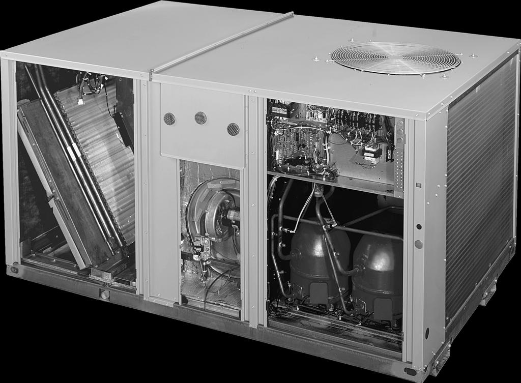
7 1. Introduction to Microcontrols The Voyager Micro was developed with two specific thoughts in mind: comfort and reliability. It provides Proportional/Integral control for superior temperature control and eliminates the need to add time delay relays or anti-short cycle times in the field. The Micro also reduces the number of parts in the control system, which means fewer parts to fail and troubleshoot. In the unlikely event that a problem does occur, the Micro s on-board diagnostics are there to assist and get you back on line fast. Trane is a pioneer in the application of microprocessor controls in the HVAC industry and has extensive experience in the design of hardware and software New Information This revised edition contains information on the following units: Voyager I & II: Voyager 3-25 ton cooling only, gas/electric, and 3-20 ton heat pumps. At the factory these are referred to as Voyager I (VI) and Voyager II (VII), which refers to cabinet size. They are grouped together in this manual because the control strategy is mostly the same regardless of tonnage. They differ only in type of heat, number of stages, etc Voyager III: Voyager ton cooling only, gas/electric and electric heat as either constant volume (CV) and variable air volume (VAV) units. At the factory these are referred to as Voyager III (VIII) or Voyager Commercial. Constant volume means that the unit is designed to provide a constant amount of air. Variable air volume means that the unit can provide a modulating quantity of air by means of inlet guide vanes (IGVs) or variable frequency drives (VFDs). Throughout this manual whenever Voyager III controls differ from Voyager I & II, look for Voyager III Notes. 6
8 2. Unitary Control Processor The Unitary Control Processor (UCP) includes the following functions: Controls decision making processes in place of a thermostat Functions as a proportional integral control for superior comfort Controls cooling & heating staging and timing Contains many other equipment protection and operational enhancement features Unitary Control Processor as a Decision Making Process 2.1. Proportional Integral Control Proportional Integral Control (PI), located in the UCP enables space temperature control by the following: Sets the corrective action proportional to the error of deviation from the set point. Sets the rate of corrective action proportional to the error, resulting in the elimination of steady state error. Proportional Integral Control as a Corrective Action 7
9 3. Zone Sensor Module The Zone Sensor Modules (ZSMs) replace a thermostat by providing the operator interface and zone temperature sensor input for the UCP. A Zone Sensor Module (ZSM) is required for each constant volume system, unless a Conventional Thermostat Interface (CTI), or VariTrac II with CCP is being used. Voyager III Note: Variable Air Volume (VAV) units, ton can use similar controllers, or they can be operated from the VAV panel in the rooftop unit. For more information see section 8.8. ZSMs are available with the following features: Remote sensing capabilities Space temperature averaging capabilities Single or Dual set point Programmable models Manual & Auto changeover Very simple to use 3.1. Installation Differences between Microcontrol & Electromechanical Wiring There are differences between microelectronic control units and electromechanical units. The most obvious difference is that typical industry terminal designations are not used. In other words, R-G-Y-W-B are not used. This is a very big change, but in reality it is a simplification. Terminal designations are now etc. The terminal designations on the Zone Sensor Modules (ZSMs) are identical to the terminal designations on the Low Voltage Terminal Board (LTB). No more wondering what thermostat terminal goes to what unit terminal. Customer control wiring connections are as simple as: 1 to 1, 2 to 2, 3 to 3, 4 to 4, 5 to 5, and so on. Voyager III note: VAV units use the VAV set point panel for supply air and morning warm-up set points. 8
10 Obsolete Zone Sensor Module Descriptions Accessory Zone Sensor Required # Terminal Model # Module Description Conductors Description Heat/Cool BAYSENS006A Single Set Point 4 1,2,3,4 ASYSTAT661A Manual Change Over BAYSENS008A Dual Set Point 5 1,2,3,4,5 ASYSTAT663A Manual / Auto Change Over BAYSENS010A Dual Set Point with 10 1,2,3,4,5, LEDs Manual / Auto 6,7,8,9,10 Change Over BAYSENS019A/020A Programmable with 3-7 ASYSTAT666A Night Setback and 12,14 LCD Indicators 7-10 Optional Heat Pump BAYSENS007A Single Set Point 6 1,2,3,4, ASYSTAT662A Manual Change Over 6,7 BAYSENS009A Dual Set Point 7 1,2,3,4,5, ASYSTAT664A Manual / Auto 6,7 Change Over BAYSENS011A Dual Set Point with 10 1,2,3,4,5, LEDs Manual / Auto 6,7,8,9,10 Change Over BAYSENSO23A Programmable with 3-7 7,8,9,10,11, ASYSTAT667A Night Setback and 12,14 LCD Indicators 7-10 Optional Heat / Cool Or Heat Pump BAYSENS012A Programmable with 2 11,12 ASYSTAT665A Night Setback BAYSENS018A Programmable with 6 7,8,9,10, Night Setback and 11,12 LCDs BAYSENS022A Digital with LCD 3 11,12,14 Temperature Display Tracer / Tracker / ComforTrac ICS BAYSENS013A Override Sensor 2 1,2 BAYSENS013B BAYSENS014A Override Sensor 3 1,2,3 BAYSENS014B with Set Point 9
11 ZSM Current Zone Sensor Module Descriptions Accessory Zone Sensor Required # Terminal Model # Module Description Conductors Connections Heat/Cool BAYSENS006B Single Set Point 4 1,2,3,4 ASYSTAT661B Manual Change Over BAYSENS008B Dual Set Point 5 1,2,3,4,5 ASYSTAT663B Manual / Auto Change Over BAYSENS010B Dual Set Point with 10 1,2,3,4,5, LEDs Manual / Auto 6,7,8,9,10 Change Over BAYSENS017B Remote sensor 2 1, 2 BAYSENS019B/020B Programmable with 3-7 7,8,9,10, ASYSTAT666B Night Setback and 11,12,14, LCD Indicators 7-10 optional BAYSENS021A VAV Remote Panel 4-9 1,2,3,4,6,7, w/out Night Setback 8,9, optional Heat Pump BAYSENS007B Single Set Point 6 1,2,3,4, ASYSTAT662B Manual Change Over 6,7 BAYSENS009B Dual Set Point 7 1,2,3,4,5, ASYSTAT664B Manual / Auto 6,7 Change Over BAYSENS011B Dual Set Point with 10 1,2,3,4,5, LEDs Manual / Auto 6,7,8,9,10 Change Over BAYSENS017B Remote sensor 2 1, 2 BAYSENS019B Programmable with 3-7 7,8,9,10, ASYSTAT666B Night Setback and 11,12,14, LCD Indicators 7-10 optional Tracer / Tracker / ComforTrac ICS BAYSENS013C Override Sensor with 2 1,2 Override / Cancel BAYSENS014C Override Sensor with 3 1,2,3 Set Point and Override / Cancel 10
12 3.4. ZSM Control Wiring Tables Control Wiring Tables Standard Zone Sensor Module Conventional Thermostat Wire Size Maximum Wire Length Wire Size Maximum Wire Length 22-gauge 150 feet 22-gauge 30 feet 20-gauge 250 feet 20-gauge 50 feet 18-gauge 375 feet 18-gauge 75 feet 16-gauge 600 feet 16-gauge 125 feet 14-gauge 975 feet 14-gauge 200 feet Zone Sensor Module (ZSM) to Low Voltage Terminal Board (LTB), and Remote Sensor to Zone Sensor Module (ZSM). Wire Type = Standard Thermostat Wire, solid conductor Note: Total resistance must not exceed 5 Ohms, or ZSM calibration / accuracy may be affected. Conventional Thermostat Interface (CTI) Installation. Voyager III Note: CTI can be used on constant volume units only. Standard Thermostat to Low Voltage Terminal Board (LTB). Wire Type = Standard Thermostat Wire, Solid Conductor. Note: Total resistance must not exceed 1 Ohm; or CTI and low voltage transformer will be over powered. Remote Sensor to Programmable ZSM Type = Shielded Twisted Pair of Conductors. Specification = 18-gauge / Belden 8760 or equivalent. Length = 1,000 feet, or less. Integrated Comfort System (ICS) Device Type = Shielded Twisted Pair of Conductors. Specification = 18-gauge / Belden 8760 or equivalent. Length = 5,000 feet, or less. 11
13 4. Equipment Protection / Operation Timings And Features Increased Reliability Fewer components (moving electromechanical parts); less likelihood of equipment down time or failure. Standard Proportional Integral (PI) Control Proportional - sets corrective action proportional to deviation from set point. Integral - fine-tunes the rate of corrective action proportional to the error (results in superior temperature control). Standard Built In TEST Mode- Aids in quick verification of system and control operation; exercises both hardware and software (no special tools required). Standard On Board Diagnostics Assists with equipment troubleshooting if a problem should occur. Standard Low Ambient Start Timer (LAST) Function Bypasses low pressure control when a compressor starts, eliminating nuisance compressor lockouts. Standard Anti Short Cycle Timer (ASCT) Function Provides a three (3) minute minimum ON time and a three (3) minute minimum OFF time for compressors; enhances compressor reliability by ensuring proper oil return. Standard Time Delay Relay (TDR) Function Provides an incremental staging delay between compressors; minimizes equipment current inrush and consumption by keeping compressors from starting simultaneously. Standard Built In Fan Delay Relay (FDR) Function Provides custom indoor fan timing sequences for the different types of equipment, enhancing efficiency and reliability. Standard Built In Evaporator Defrost Control Function Provides low ambient cooling down to 0 F. Standard Built in Froststat for Voyager ton units - Provides low ambient cooling down to 0 F. Standard Integral Electric Heat Staging Stages electric heaters OFF and ON, eliminating the use of sequencers. Standard Intelligent Fallback Built in Default Control provides adaptive operation, which allows the equipment to continue to operate, and provide comfort in the event of certain input failures. Also, allows temporary operation without a Zone Sensor Module (ZSM). Standard Emergency Stop Terminals on Low Voltage Terminal Board (LTB-16 & LTB-17) Provides a convenient point to disable the equipment completely and immediately. Standard Lower Installation Cost When using a standard Zone Sensor Module (ZSM), control voltage wiring may be run up to five (5) times further than any electromechanical system with no increase in wire gauge. Example: Electromechanical System - 75 feet using 18-gauge wire. Microcontrol System feet using 18 gauge wire. Standard Alternating Lead/Lag Note: Dual Compressor or Dual Circuit Models Only. During periods of part load operation, each compressor cycles alternately as circuit number one, equalizing compressor wear and run time. Enabled by cutting the wire at UCP junction number J1-7. Standard 12
14 Demand Defrost on Ton Heat Pumps Defrosts only if needed; not based on time like most other systems. Adapts to changing weather conditions and lowers operating costs. Standard Heat Pump on 3-20 Ton Soft Start Provides a smooth transition into heating after defrost, minimizing noise and compressor stress associated with switch over. Standard Heat Pump on 3-20 Ton Smart Recovery and Smart Staging Inhibits auxiliary heat operation if the space is recovering adequately (0.1 F./minute) with the heat pump alone, providing considerable savings in operating costs. Standard Remote Sensing All Zone Sensor Modules (ZSMs) have remote sensing capabilities. Standard Space Temperature Averaging All standard ZSMs have space temperature averaging capabilities. Note: Requires a minimum of four (4) remote sensors. Supply Air Tempering A built in feature enabled using a programmable ZSM or ICS device. When in the HEAT mode (and not actively heating), if supply air temperature drops 10 F. below the heating set point, heat is turned on until supply air temperature rises to a point 10 F. above the heating set point. Provides temperate air during the OFF cycle, and eliminates cold air dumping from supply ducts. Extremely effective when introducing large quantities of fresh air. Built In Night Set Back And Unoccupied Functions When using a standard dual set point/auto change over ZSM, enable this function by applying a short across terminals LTB- 11 and LTB-12. Sets cooling set point up a minimum of 7 F., sets heating set point back a minimum of 7 F., forces outside air damper (if present) minimum position to zero, and forces fan operation to automatic. Accessory (requires time clock accessory or field supplied/installed switch or contacts) When using a standard single set point/manual change-over ZSM setback/setup will not occur but other unoccupied functions will. Accessory (requires time clock accessory or field supplied/installed switch or contacts). See defaults, Section 8.8 for more information. Voyager III Note: For VAV- mechanical cooling is disabled, outside air damper will close, and the fan stays off except for unoccupied heating mode (if present). IGVs and VAV boxes are forced open during transition from occupied to unoccupied. Selectable Economizer Dry Bulb Change Over Allows the capability of selecting the following dry bulb change over points: 55, 60 or 65 F. Standard with economizer Economizer Preferred Cooling Provides fully integrated operation. Will not turn on a compressor with the economizer, if the space is recovering adequately with the economizer alone (0.2 F./minute). Allows the equipment to be utilized in more varied applications. Standard with economizer Morning warm-up Control (VAV units) With a programmable sensor, ICS device or standard VAV set point panel. Daytime warm-up Control (VAV units) When using morning warm-up, the daytime control is available or can be disabled. Standard 13
15 5. Equipment Operation with a Conventional Thermostat Interface (CTI) When a CTI and a conventional mechanical thermostat are applied to the unit, operation differs. Thermostat logic is different; therefore some features discussed previously are not available. They are as follows: The Supply Air Tempering feature is not available. If outdoor air is being introduced through the equipment, discharge air temperature may be cold when not actively heating. Proportional Integral (PI) control is not available. On Board Diagnostics are only available on the Unitary Control Processor (UCP) at the J7 pins, instead of the Low Voltage Terminal Board (LTB). Intelligent Fall Back is not available. If a failure occurs in the device controlling the equipment, operation will cease. Heat Pump Smart Recovery and Smart Staging is not available. Heat Pump operation becomes more costly unless the generic control being applied can accomplish this. Remote Sensing Capabilities are not available on mechanical thermostats. Space Temperature Averaging capabilities are not available on mechanical thermostats. Built in Night Set Back and Unoccupied Functions are not available on mechanical thermostats. Built in Unoccupied mode is not available on mechanical thermostats. Notes: Installation can be more costly. In addition to the price of Conventional Thermostat Interface and the thermostat or generic control, the control wiring size must be increased. Troubleshooting becomes more complex, because of the additional hardware (i.e. CTI Module). Voyager III Notes: 1) Not an option on VAV units. 2) On CV units the unit is limited to 2 stages of cooling. 14
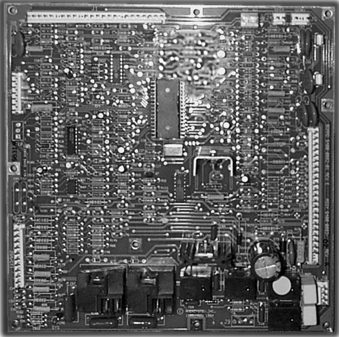
16 6. Microcontrol Component Descriptions and Part Numbers 6.1. Unitary Control Processor (UCP) Main board in the unit control box, which is standard in all microcontrol units. The computer and program reside in this board. This is the brain of the control system. Component Description Unitary Control Processor (UCP) 3-25 tons Unitary Control Processor (UCP) tons Part Number MOD MOD Unitary Economizer Module (UEM) Board located in economizer section on 3-25 ton units, and unit control box on ton units. Standard in all microcontrol economizers, motorized outside air dampers, and BAYDIAG001A. Allows UCP to directly control the economizer actuator (ECA). This is the hardware interface between the UCP and the economizer actuator (ECA) motor. Component Description Unitary Economizer Module (UEM) MOD-0145 Part Number 15
17 6.3. Unitary VAV Module (UVM) Standard board located in unit control box on Ton VAV units. Provides a 2 to 10 VDC output to control Inlet Guide Vanes or Variable Frequency Drive. Component Description Part Number Unitary VAV Module (UVM) MOD Defrost Module (DFM) Small board located in the unit control box. Standard in ton microcontrol heat pumps only. Provides time / temperature input to the UCP for time / temperature defrost. Component Description Defrost Module (DFM) Part Number BRD
18 6.5. Conventional Thermostat Interface (CTI) Accessory (BAYCTHI001C) field or factory installed board, mounted in unit control box to the right of the UCP board. Allows system to be operated by a conventional thermostat or through dry contact closure type controls. The only difference in hardware between VI/VII/VIII is the cable length from the UCP to the CTI. Can only be used on constant volume units. Component Description Conventional Thermostat Interface (CTI) Part Number BRD Trane Communications Interface (TCI-3) Accessory (BAYICSI001B) field or factory installed board, mounted in unit control box to the right of the UCP board. Allows system to communicate with, and be controlled by Tracer, the Tracker STAT 4/7/16 series, and VariTrac bypass VAV system. Voyager III (VAV) Note: VariTrac can not be used with Voyager III VAV. Used with constant volume units only. Note: Obsolete ComforTrac and VariTrac Comfort Manager also require this interface. Component Description Trane Communications Interface (TCI-3) Part Number BRD
19 6.7. Obsolete Trane Communications Interface (TCI-1) Accessory field installed board, mounted in unit control box to the right of the UCP board. Allows system to communicate with, and be controlled by, Tracer / Tracker / ComforTrac Integrated Comfort System (ICS) Building Management Devices. For Replacement use TCI-3 Trane Communications Interface (TCI-3) Part Number BRD Obsolete Trane Communications Interface (TCI-2) Accessory field installed board, mounted in unit control box to the right of the UCP board. Allows system to communicate with, and be controlled by, VariTrac Comfort Manager zoning system. For Replacement use TCI-3 Trane Communications Interface (TCI-3) Part Number BRD
20 6.9. Obsolete BAYSENS006A / ASYSTAT661A Accessory Heat / Cool Zone Sensor Module (ZSM), single set point, manual change over. Four conductors required. Manufactured by Sunne prior to 12/93. For Replacement use BAYSENS006B & Wall Plate BAYMTPL004A BAYSENS006B [Sunne part# 62822] ASYSTAT661B [Sunne part# 62830] Part Number SEN-0410 SEN Obsolete BAYSENS007A / ASYSTAT662A Accessory Heat Pump Zone Sensor Module (ZSM), single set point, manual change over. Six conductors required. Manufactured by Sunne prior to 12/93. For Replacement use BAYSENS007B & Wall Plate BAYMTPL004A BAYSENS007B [Sunne part# 62821] ASYSTAT662B [Sunne part# 62831] Part Number SEN-0411 SEN
21 6.11. Obsolete BAYSENS008A / ASYSTAT663A Accessory Heat / Cool Zone Sensor Module (ZSM), dual set point, manual / auto-change over. Five conductors required. Manufactured by Sunne prior to 12/93. For Replacement use BAYSENS008B & Wall Plate BAYMTPL004A BAYSENS008B [Sunne part# 62826] ASYSTAT663B [Sunne part# 62833] Part Number SEN-0408 SEN Obsolete BAYSENS009A / ASYSTAT664A Accessory Heat Pump Zone Sensor Module (ZSM), dual set point, manual / auto-change over. Seven conductors required. Manufactured by Sunne prior to 12/93. For Replacement use BAYSENS009B & Wall Plate BAYMTPL004A BAYSENS009B [Sunne part# 62825] ASYSTAT664B [Sunne part# 62832] Part Number SEN-0412 SEN
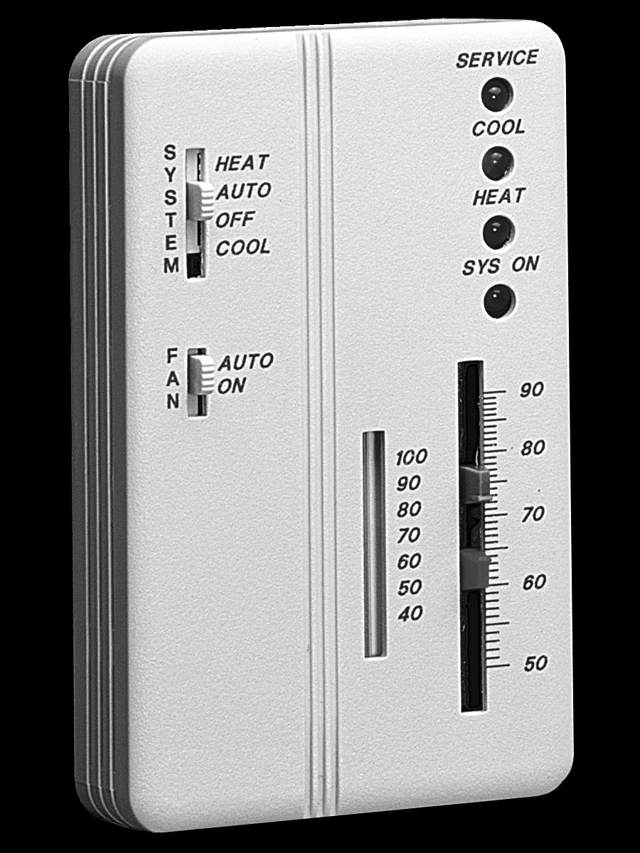
22 6.13. Obsolete BAYSENS010A Accessory Heat / Cool Zone Sensor Module (ZSM), dual set point with LEDs, manual / auto-change over. Ten conductors required. Manufactured by Sunne prior to 12/93. For Replacement use BAYSENS010B & Wall Plate BAYMTPL004A BAYSENS010B [Sunne part# 62823] Part Number SEN Obsolete BAYSENS011A Accessory Heat Pump Zone Sensor Module (ZSM), dual set point with LEDs, manual / auto-change over. Ten conductors required. Manufactured by Sunne prior to 12/93. For Replacement use BAYSENS011B & Wall Plate BAYMTPL004A BAYSENS011B [Sunne part# 62824] Part Number SEN
23 6.15. Obsolete BAYSENS012A / ASYSTAT665A Accessory Heat / Cool and Heat Pump, programmable night set back Zone Sensor Module (ZSM). Two conductors required. Manufactured by Enerstat/Valera prior to 02/94. For Replacement use BAYSENS019B Part Number BAYSENS019B [Caradon part# 91K91] SEN-0874 ASYSTAT666B [Caradon part# 91K92] SEN-0907 Note: Minimum of 3 wires required with a BAYSENS019B Obsolete BAYSENS013A Accessory ICS (Tracer/Tracker/ComforTrac) Zone Sensor Module (ZSM), with override button. Two conductors required. Manufactured by Sunne prior to 12/93. For Replacement use BAYSENS013C & Wall Plate BAYMTPL004A BAYSENS013C [Sunne part# 65464] Part Number SEN
24 6.17. Obsolete BAYSENS013B Accessory ICS (Tracer/Tracker/ComforTrac) Zone Sensor Module (ZSM), with override button. Two conductors required. Manufactured by Sunne, prior to 08/95. For Replacement use BAYSENS013C BAYSENS013C [Sunne part# 65464] Part Number SEN Obsolete BAYSENS014A Accessory ICS (Tracer/Tracker/ComforTrac) Zone Sensor Module (ZSM), with override button and set point. Three conductors required. Manufactured by Sunne prior to 12/93. For Replacement use BAYSENS014C & Wall Plate BAYMTPL004A BAYSENS014C [Sunne part# 65465] Part Number SEN
25 6.19. Obsolete BAYSENS014B Accessory ICS (Tracer/Tracker/ComforTrac) Zone Sensor Module (ZSM), with override button and set point. Three conductors required. Manufactured by Sunne, prior to 08/95. For Replacement use BAYSENS014C BAYSENS014C [Sunne part# 65465] Part Number SEN Obsolete BAYSENS017A Accessory Zone Sensor Remote, used with BAYSENS006A, 007A, 008A, 009A, 010A or 011A. Two conductors required. Manufactured by Sunne prior to 12/93. For Replacement use BAYSENS017B & Wall Plate BAYMTPL004A BAYSENS017B [Sunne part# 62828] ASYSTAT669A [Sunne part# 65541] Part Number SEN-0435 SEN
26 6.21. Obsolete BAYSENS018A Accessory Heat / Cool and Heat Pump, programmable night set back Zone Sensor Module (ZSM), with LCD status / diagnostic indicators. Six conductors required. Manufactured by Enerstat/Valera prior to 02/94. For Replacement use BAYSENS019B & Wall Plate BAYMTPL003A Part Number BAYSENS019B [Caradon part# 91K91] SEN-0874 ASYSTAT666B [Caradon part# 91K92] SEN Obsolete BAYSENS019A/020A/ASYSTAT666A Accessory Heat/Cool, programmable night set back Zone Sensor Module (ZSM), with LCD status / diagnostic indicators. Seven conductors, terminals 11, 12 & 14 required, 7 through 10 optional. Manufactured by Caradon, introduced 03/94. For Replacement use BaYSENS019B/020B & Wall Plate BAYMTPL003A Part Number BAYSENS019B [Caradon part# 91K91] SEN-0874 ASYSTAT666B [Caradon part# 91K92] SEN-0907 BAYSENS020B [Caradon part# 91K93] (VAV only) SEN
27 6.23. Obsolete BAYSENS022A Accessory Heat / Cool and Heat Pump, (non-programmable) digital Zone Sensor Module (ZSM), with LCD display. Three conductors required. Manufactured by Enerstat/Valera, introduced 06/93. No Replacement Obsolete BAYSENS023A/ASYSTAT667A Accessory Heat Pump, programmable night set back Zone Sensor Module (ZSM), with LCD status / diagnostic indicators. Seven conductors, terminals 11, 12 & 14 required, 7 through 10 optional. Manufactured by Caradon, introduced 03/94. For Replacement use BAYSENS019B & Wall Plate BAYMTPL003A Part Number BAYSENS019B [Caradon part# 91K91] SEN-0874 ASYSTAT666B [Caradon part# 91K92] SEN
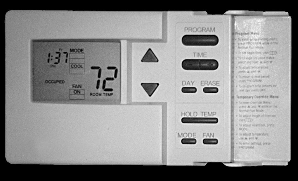
28 6.25. Obsolete Programmable Zone Sensor Modules The programmable zone sensor module is a night set back device with 7 day programming capabilities, and one occupied / unoccupied period per day. Two wires are required for BAYSENS012A or ASYSTAT665A installation. BAYSENS018A required 6 wires. A microprocessor in the zone sensor communicates with the UCP once every 0.5 seconds. BAYSENS012A, 018A Obsolete Programmable Zone Sensor Modules The programmable zone sensor module, is a night set back device with many features. It has 7 day programming capabilities, with two occupied, and two unoccupied periods per day. Three wires are required for BAYSENS019A/023A or ASYSTAT666B basic installation. When remote panel indication is needed, up to seven wires are used to complete installation. Its microprocessor communicates once every 0.5 seconds with the UCP, for rapid response to zone changes. 27
29 7. Microcontrol Accessories and What They Offer 7.1. BAYSENS006B/ASYSTAT661B Accessory Heat / Cool Zone Sensor Module (ZSM), single set point, manual change over. Four conductors required. Manufactured by Sunne, introduced 12/93. Component Description BAYSENS006B [Sunne part# 62822] ASYSTAT661B [Sunne part# 62830] Part Number SEN-0410 SEN BAYSENS007B / ASYSTAT662B Accessory Heat Pump Zone Sensor Module (ZSM), single set point, manual change over. Six conductors required. Manufactured by Sunne, introduced 12/93. Component Description BAYSENS007B [Sunne part# 62821] ASYSTAT662B [Sunne part# 62831] Part Number SEN-0411 SEN
30 7.3. BAYSENS008B / ASYSTAT663B Accessory Heat / Cool Zone Sensor Module (ZSM), dual set point, manual / auto change over. Five conductors required. Manufactured by Sunne, introduced 12/93. Component Description BAYSENS008B [Sunne part# 62826] ASYSTAT663B [Sunne part# 62833] Part Number SEN-0408 SEN BAYSENS009B / ASYSTAT664B Accessory Heat Pump Zone Sensor Module (ZSM), dual set point, manual / auto change over. Seven conductors required. Manufactured by Sunne, introduced 12/93. Component Description BAYSENS009B [Sunne part# 62825] ASYSTAT664B [Sunne part# 62832] Part Number SEN-0412 SEN
31 7.5. BAYSENS010B Accessory Heat / Cool Zone Sensor Module (ZSM), dual set point with LEDs, manual / auto change over. Ten conductors required. Manufactured by Sunne, introduced 12/93. Component Description BAYSENS010B [Sunne part# 62823] Part Number SEN BAYSENS011B Accessory Heat Pump Zone Sensor Module (ZSM), dual set point with LEDs, manual / auto change over. Ten conductors required. Manufactured by Sunne, introduced 12/93. Component Description BAYSENS011B [Sunne part# 62824] Part Number SEN
32 7.7. BAYSENS013C Accessory ICS (Tracer/Tracker/ComforTrac) Zone Sensor Module (ZSM), with override button, and override cancel button. Two conductors required. Manufactured by Sunne, introduced 08/95. Component Description BAYSENS013C [Sunne part# 65464] Part Number SEN BAYSENS014C Accessory ICS (Tracer/Tracker/ComforTrac) Zone Sensor Module (ZSM), with override button, set point, and override cancel button. Three conductors required. Manufactured by Sunne, introduced 08/95. Component Description BAYSENS014C [Sunne part# 65465] Part Number SEN
33 7.9. BAYSENS015A Humidity Sensor (OHS, RHS) Outdoor Humidity Sensor: Field installed accessory, located below and to the left of economizer actuator motor. Used in reference (BAYENTH003A) and comparative (BAYENTH004A) enthalpy control. Return Humidity Sensor: Field installed accessory, located inside economizer barometric relief hood. Used in comparative (BAYENTH004A) enthalpy control only. (Honeywell #C7600A1028) Component Description BAYSENS015A Humidity Sensor (OHS, RHS) Part Number SEN BAYSENS016A Thermistor Sensor (OAS, SAS, RAS, CTS) Outdoor Air Sensor: Located in corner post by unit control box on Voyager I and II units. Located in the economizer section on Voyager Commercial units. Comes standard on all microcontrol units. Supply Air Sensor: Field installed in supply fan housing for Voyager I and II units. Factory installed in supply fan housing for Voyager III units. Comes standard with all microcontrol economizers, or BAYDIAG001A (Generic Input/Output Module) used to gain additional points on ICS jobs when economizers are not used. Return Air Sensor: Field installed accessory. Located in barometric relief hood of economizer accessory, used in comparative enthalpy control only (BAYENTH004A accessory). Coil Temperature Sensor: Located in a 3/8" copper tube well, which is brazed to the lowest circuit entering the outdoor coil (3-7.5 ton heat pumps only). Component Description Thermistor Sensor (OAS, SAS, RAS) Part Number SEN
34 7.11. BAYSENS017B / ASYSTAT669A Accessory Zone Sensor Remote, used with all current zone sensors. Two conductors required. Manufactured by Sunne, introduced 12/93. Component Description BAYSENS017B [Sunne part# 62828] ASYSTAT669A [Sunne part# 65541] Part Number SEN-0435 SEN BAYSENS019B / ASYSTAT666B (CV 3-50 Ton) Accessory Heat/Cool, programmable night set back Zone Sensor Module (ZSM), with LCD status / diagnostic indicators. Seven conductors: terminals 11, 12 & 14 required, 7 through 10 optional. Manufactured by Caradon, introduced 06/98. Component Description Part Number BAYSENS019B [Caradon part# 91K91] SEN-0874 ASYSTAT666B [Caradon part# 91K92] SEN
35 7.13. BAYSENS020B (Voyager III VAV only) Accessory Heat/Cool, programmable night set back Zone Sensor Module (ZSM) for VAV applications, with LCD status / diagnostic indicators. Seven conductors: terminals 11, 12 & 14 required, 7 through 10 optional. Manufactured by Caradon, introduced 06/98. Component Description Part Number BAYSENS020B [Caradon part# 91K93] SEN BAYSENS021B (Voyager III VAV only) Accessory Zone Sensor Module (ZSM) for VAV applications, single set point with LEDs, system auto or off. Nine conductors, terminals 1, 2, 4, & 5 required, 6 through 10 optional. Component Description BAYSENS021A Part Number SEN
36 7.15. Electronic Time Clock The BAYCLCK001A / ASYSTAT668A has a 16 digit LCD display and provides set up / set back for multiple units (up to four), when used in conjunction with a standard dual setpoint zone sensor module (see YC-EB-1 for sequence of operation details). The electronic time clock is a true 7 day programmable device which offers one occupied and one unoccupied mode per day, and a smart copy feature allows Monday s program to be copied to every other day (upon initial power up). The time clock contains four separate relays with normally open contacts. Each set of contacts should be wired to terminals LTB- 11 and LTB-12. The normally open contacts may be used to power an auxiliary relay and control any generic building device or load. The time clock requires 24 VAC, provided by unit terminals LTB-16 and LTB-20 (or LTB-15 and LTB-16 on equipment produced prior 07/93). Component Description Part Number BAYCLCK001A TWR-0115 ASYSTAT668A TWR
37 7.16. High Temperature Sensor The high temperature sensor accessory (BAYFRST001A) provides high limit cutout with manual reset in ICS device Tracer / Tracker / ComforTrac / VariTrac systems. The sensors are wired to the TB-1 on the Trane Communications Interface (TCI). The sensors may be used to detect heat from a fire in air conditioning or ventilation ducts and provide system shut down to contain the fire. Approximately 30 seconds after sensor opens, the associated unit will completely shut down. The sensors come with case and cover, and mount directly to the ductwork. There are two sensors that are included in the accessory. Both sensors are factory set; one opens at 135 F. and should be installed in the return air duct, the other opens at 240 F. and should be installed in the supply duct. Note: This accessory can also be applied in Non-ICS applications and wired between terminals LTB-16 and LTB-17 at the low voltage terminal strip. The unit will shut down immediately when the sensor opens. To reset a sensor which has opened, push and release the button protruding through the cover. See reset button. The sensor temperature must drop 25 F. below the cut out point before it will reset. There are no field adjustments that can be made to the sensor; if a problem exists, the sensor must be replaced. Part Number "CNT-0637" = 135 F. sensor. Part Number "CNT-0638" = 240 F. sensor. Component Description Part Number BAYFRST001A CNT-0637 & CNT
38 37
39 Section 2 8. Start Up From the Unit "Test Mode Feature" 8.1. Step Test Mode Utilizing the sight hole in the lower left-hand corner of the of the control box front panel, verify that the LED on the UCP is on continuously. (The cover panel does not require removal.) Initiate the test mode by shorting across the "TEST" terminals on the unit's Low Voltage Terminal Board (LTB) for two to three seconds, and then removing the short. The LED on the UCP will blink indicating the unit is in the test mode, and the indoor fan motor (IDM) is turned on (STEP1). The unit may be left in any step for up to one hour to allow for troubleshooting. If left in any one mode, after approximately one hour, the UCP will exit the test mode. To step into the next mode, short across the "TEST" terminals for 2 to 3 seconds, and remove the short. See test mode table. The UCP will skip the steps marked with *, or **, if they are not a feature or accessory on this unit. Exit the test mode by cycling unit power with the disconnect switch (off & on), or by stepping through the test steps, until the UCP's LED stops flashing Auto Test Mode This test mode is the most useful during initial system start up. The entire duration of the test will last from seconds depending on the unit, and accessories installed. Initiate the Auto Test Mode by installing a jumper across the "TEST" terminals on the unit's Low Voltage Terminal Board (LTB). The LED on the UCP will begin to blink, indicating the unit is in the test mode. The unit will cycle through the test steps in sequence, one time, changing test steps every 30 seconds. Note: power to the unit must be on prior to placing the jumper on TEST 1 & 2. The UCP will skip the steps marked with *, or **, if they are not a feature or accessory on this unit. Terminate the Auto Test Mode by removing the jumper from the "TEST" terminals, and cycling the unit power with the disconnect switch (off & on). If the unit is inadvertently left in the Auto Test Mode with the jumper left in place, the UCP will automatically exit the test mode and ignore the jumper Resistance Test Mode This test mode is used to force the unit into a specific test step. A selection of resistors or a decade resistor box (BAYSERV001A) is required. This takes the guess-work out of which test step the unit is in. Initiate the Resistance Test Mode by installing the proper resistor across the "TEST" terminals on the unit's Low Voltage terminal Board (LTB). The LED on the UCP will begin to blink, indicating the unit is in the test mode, and the system will operate in the desired mode. Terminate the Resistance Test Mode by removing the resistor from the "TEST" terminals, and cycling the unit power with the disconnect switch (off & on). If the unit is inadvertently left in the Resistance Test Mode, the UCP will automatically exit the test mode after one hour, and ignore the resistor across the "TEST" terminals. 38
Engineering Bulletin. IntelliPak RTM (Rooftop Module, 1U48) Subject: Generic Building Automation System (GBAS, UCM Module, 1U51)
 Subject: Generic Building Automation System (GBAS, UCM Module, 1U51)") Engineering Bulletin IntelliPak RTM (Rooftop Module, 1U48) Subject: Generic Building Automation System (GBAS, UCM Module, 1U51) Issued By: Clarksville Marketing and Sales Support Order No. UN-PRB001-EN
Engineering Bulletin IntelliPak RTM (Rooftop Module, 1U48) Subject: Generic Building Automation System (GBAS, UCM Module, 1U51) Issued By: Clarksville Marketing and Sales Support Order No. UN-PRB001-EN
Installers Guide. Trane Communications Interface ( Comm3 / Comm4 )
") ACC-SVN18C-EN Installers Guide Trane Communications Interface ( Comm3 / Comm4 ) Models: BAYICSI003A BAYICSI004B Used With: 3-10 Ton Packaged Rooftop units with Reliatel Communications Module, 7½ - 20 Ton
ACC-SVN18C-EN Installers Guide Trane Communications Interface ( Comm3 / Comm4 ) Models: BAYICSI003A BAYICSI004B Used With: 3-10 Ton Packaged Rooftop units with Reliatel Communications Module, 7½ - 20 Ton
Metasys Zoning Package Installation
 Technical Bulletin Issue Date August 28, 2002 Metasys Zoning Package Installation Metasys Zoning Package Installation...2 Introduction... 2 Key Concepts... 3 Installation Overview... 3 Metasys Zoning Package
Blank-off. HVAC unit screws. Spacer for 1" filter ILL. 3. Screw
 ICP INSTALLATION INSTRUCTIONS for NPECOMZR00A00 ICP's economizer is convertible-it will work in either a down discharge or horizontal discharge application. Read these instructions completely and carefully
ZIP Economizer Fault Detection and Diagnostics (FDD) Table
 Table") Fault Detection and Diagnostics (FDD) Table Fault Detection Problem Diagnostic ction (in addition to alarm stored / transmitted) Potential Cause C Fault Code OT sensor predetermined range O damper returns
Fault Detection and Diagnostics (FDD) Table Fault Detection Problem Diagnostic ction (in addition to alarm stored / transmitted) Potential Cause C Fault Code OT sensor predetermined range O damper returns
HP21 SERVICE SUPPLEMENT UNIT INFORMATION. TSC6 Two-Speed Control
 SERVICE UNIT INFORMATION SUPPLEMENT HP21 Corp. 9426 L10 Litho U.S.A. All HP21-4 and -5 units (single and three phase) are equipped with a TSC6 two-speed control. The TSC6 (A14) two-speed control contains
ECONOMIZERS. 5/2012 Supersedes
 Litho U.S.A. 2012 ECONOMIZERS 507031 01 5/2012 Supersedes 506747 01 K1ECON ECONOMIZERS INSTALLATION INSTRUCTIONS FOR ECONOMIZERS AND OUTDOOR AIR HOODS USED WITH KG/KC/KH 024, 030, 036, 048, 060, 072, 090
PERFORMANCE DATA TYPICAL FIELD WIRING CERTIFIED DIMENSION PRINTS CERTIFIED ROOF CURB DIMENSION PRINTS
 50FP-1SB 50FP034, 038, 044, 048, 054, 064, 074 SINGLE-PACKAGE COOLING UNITS CONSTANT/VARIABLE VOLUME PRODUCT INTEGRATED CONTROLS CARRIER COMFORT NETWORK COMPATIBLE FACTORY-INSTALLED OPTIONAL ELECTRIC HEAT
Installation Manual. Mixing Box Control Systems Installation, Operation, and Maintenance Manual. 605 Shiloh Road Plano, Texas
 Installation Manual IOM-MBC-00 08-30-04 Mixing Box Control Systems Installation,, and Maintenance Manual Contents Page Introduction...1 General...1 Safety...1 Inspection...1 Mixing Box Control Systems...2
EconoMi$er, Power Exhaust, and Sensor Installation Instructions
 Small Rooftop Units Gas Heating/Electric Cooling, Electric Cooling, and Heat Pump Units 3 to.5 Tons (50/60 Hz) EconoMi$er Package for Vertical and Horizontal Duct Systems Issue Date /0/0 EconoMi$er, Power
Screw. (Note 4) Spacer for 1" filter ILL. 3. Screw
 Spacer for 1 filter ILL. 3. Screw") ICP INSTALLATION INSTRUCTIONS for (NPECOMZR006A00) ICP's economizer is convertible-it will work in either a down discharge or horizontal discharge application. Read these instructions completely and carefully
ICP INSTALLATION INSTRUCTIONS for (NPECOMZR006A00) ICP's economizer is convertible-it will work in either a down discharge or horizontal discharge application. Read these instructions completely and carefully
Screw. (Note 4) Spacer for 1" filter ILL. 3. Screw
 Spacer for 1 filter ILL. 3. Screw") MicroMetl INSTALLATION INSTRUCTIONS for 0637-0311 (CPECOMZR006A00) MicroMetl's 0637 economizer is convertible-it will work in either a down discharge or horizontal discharge application. Read these instructions
MicroMetl INSTALLATION INSTRUCTIONS for 0637-0311 (CPECOMZR006A00) MicroMetl's 0637 economizer is convertible-it will work in either a down discharge or horizontal discharge application. Read these instructions
Installation Instructions
 024A02 025A02 SMALL ROOFTOP UNITS HORIZONTAL ECONOMI$ER IV ACCESSORY 2TO12-1/2TONS Installation Instructions TABLE OF CONTENTS PACKAGE CONTENTS... 1 PACKAGE USAGE... 1 SAFETY CONSIDERATIONS... 1 GENERAL...
Installation Instructions
 020A02 021A03 008C00 SMALL ROOFTOP UNITS VERTICAL ECONOMI$ER IV ACCESSORY 2to12-1 / 2 TONS LARGE ROOFTOP UNITS VERTICAL AND HORIZONTAL ECONOMI$ER IV ACCESSORY 13 to 25 TONS Installation Instructions TABLE
Installation Instructions
 Part Number: CPECOMZR008A00 & CPECOMZR009A00 Installation Instructions Read these instructions completely before attempting to install the Vertical Accessory. CONTENTS SAFETY CONSIDERATIONS...1 GENERAL...1,2
Installation Guide. DigiTract 4. Two Stage Heat/Cool Comfort Control System. Zoning Systems. That s all we do. Part #DT4MAN. Rev.
 Installation Guide DigiTract 4 Two Stage Heat/Cool Comfort Control System Part #DT4MAN Rev. October 2013 Zoning Systems That s all we do. TABLE OF CONTENTS...Page INTRODUCTION...1 SYSTEM DESCRIPTION...1
ECONOMIZERS. 1/2012 Supersedes
 ECONOMIZERS Litho U.S.A. 2012 506948 01 1/2012 Supersedes 506394 01 K1ECON20C 1 ECONOMIZERS INSTALLATION INSTRUCTIONS FOR ECONOMIZER AND OUTDOOR AIR (604592 03; 54W77) USED WITH KG/KC/KH 180 300S UNITS
Application Engineering
 Application Engineering February, 2009 Copeland Digital Compressor Controller Introduction The Digital Compressor Controller is the electronics interface between the Copeland Scroll Digital Compressor
Installation Instructions
 Part Number: CPECOMZR011A00 & CPECOMZR012A00 Installation Instructions Read these instructions completely before attempting to install the Horizontal Accessory. CONTENTS SAFETY CONSIDERATIONS...1 GENERAL...1,2
MicroTech II Applied Rooftop Unit Controller
 Installation and Maintenance IM-696-2 Group: Applied Systems Part Number: IM696 Date: March 2004 MicroTech II Applied Rooftop Unit Controller Used with McQuay models: RPS, RFS, RCS, RDT, RPR, RFR, RPE,
SP-32 & SP-32D SP-33, SP-33D SP-34, SP-34D. Description. Specifications. Single Stage Temperature Control
 SP-32, SP-32D SP-33, SP-33D SP-34, SP-34D Single Stage Temperature Control Description The SP-3x and SP-3xD series of controls are single stage, general purpose, temperature controls with wide application
ULTRA-ZONE FORCED AIR ZONE CONTROLS EWC
 INDEX DAMPERS MOTORIZED MODEL RSD ROUND... 7-5 MODEL URD ROUND... 7-5 ND SERIES... 7-6 7-7 STATIC PRESSURE CONTROL MODEL EBD RECTANGULAR... 7-7 MODEL EBD ROUND... 7-7 MODEL PRD... 7-8 MODEL PRD-RD... 7-8
LF Series At A Glance
 LF Series Spring Return Direct Coupled Actuator Minimum 35 in-lb Torque For damper areas up to 8 sq-ft* Applications Cost effective quality and performance for a range of applications including: Classroom
Installation Guide. DigiTract 4. Two Stage Heat/Cool Comfort Control System. Zoning Systems. That s all we do. Part #DT4MAN Rev.
 Installation Guide DigiTract Two Stage Heat/Cool Comfort Control System Part #DTMAN Rev. February 008 Zoning Systems That s all we do. TABLE OF CONTENTS...Page INTRODUCTION... SYSTEM DESCRIPTION... COMPONENT
Installation Instructions
 05A00 053A00 VERTICAL AND HORIZONTAL ECONOMIZER IV ACCESSORY MEDIUM ROOFTOP UNITS 5 to 5 TONS TABLE OF CONTENTS PACKAGE USAGE... SAFETY CONSIDERATIONS... PACKAGE CONTENTS... GENERAL... ACCESSORIES LIST...
Hardware Installation. Tracer AH541 Version 2 Air-Handler Controller CNT-SVN02B-EN
 Hardware Installation Tracer AH541 Version 2 Air-Handler Controller CNT-SVN02B-EN Hardware Installation Tracer AH541 Version 2 Air-Handler Controller CNT-SVN02B-EN February 2004 CNT-SVN02B-EN Tracer AH541
Installation Instructions DNECOMZR020A02, DNECOMZR021A03 (For 3 to 12.5 Ton Units) and DNECOMZR062A00 (For RHS 12.5 Ton Heat Pump Units)
 and DNECOMZR062A00 (For RHS 12.5 Ton Heat Pump Units)") Installation Instructions DNECOMZR020A02, DNECOMZR021A03 (For 3 to 12.5 Ton Units) and DNECOMZR062A00 (For RHS 12.5 Ton Heat Pump Units) Vertical Economizer Accessory for Rooftop Units TABLE OF CONTENTS
Installation Instructions DNECOMZR020A02, DNECOMZR021A03 (For 3 to 12.5 Ton Units) and DNECOMZR062A00 (For RHS 12.5 Ton Heat Pump Units) Vertical Economizer Accessory for Rooftop Units TABLE OF CONTENTS
PERFORMANCE DATA TYPICAL FIELD WIRING CERTIFIED DIMENSION PRINT CERTIFIED ROOF CURB DIMENSION PRINTS
 50FN-1SB 50FNX,FNY078,088,104 SINGLE-PACKAGE COOLING UNITS CONSTANT/VARIABLE AIR VOLUME PRODUCT INTEGRATED CONTROLS CARRIER COMFORT NETWORK COMPATIBLE WITH INTEGRAL ECONOMIZER AND HIGH-CAPACITY MODULATING
SMT-150 Installer Manual
 SMT-150 Installer Manual 3 Stage Digital HVAC Controller Version 1.0 Version History January 2019 Version 1 - Original Document Thank you for your purchase of this premier product. Please take the time
Installation Instructions
 Part Number: CPECOMZR010A00 Read these instructions completely before attempting to install the Vertical Accessory. CONTENTS SAFETY CONSIDERATIONS...1 GENERAL...1,2 ACCESSORIES LIST...2 INSTALLATION...2-6
COMMERICAL SPLIT SYSTEM KITS AND ACCESSORIES /2014 Supersedes 8/2012
 COMMERICAL SPLIT SYSTEM KITS AND ACCESSORIES 506953-01 3/2014 Supersedes 8/2012 Litho U.S.A. MSAV Supply Air Blower VFD Kit INSTALLATION INSTRUCTIONS FOR MSAV (MULTI-STAGE AIR VOLUME) SUPPLY AIR BLOWER
Application Engineering
 Application Engineering March 2011 Copeland Digital Compressor Controller Introduction The Digital Compressor Controller is the electronics interface between the Copeland Scroll Digital compressor or the
MicroTech II Applied Rooftop Unit Controller
 ( Installation and Maintenance IM-696 Group: Applied Systems Part Number: IM696 Date: April 21 MicroTech II Applied Rooftop Unit Controller Used with McQuay models: RPS, RFS, RCS, RDT, RPR, RFR, RDS, RAR
SE8300 Series Installation Guide 24 Vac Low Voltage
 Installation Guide 24 Vac Voltage mercial and Hotel/Lodging HVAC Fan Coil Applications CONTENTS Installation 2 Configurable BI/UI Universal Inputs Overview 3 Setup Screen Display 3 Terminal Identification
SLIMZONE CLASSIC /
 SLIMZONE CLASSIC 2701-001 / 2701-006 ZONE CONTROL SYSTEM INSTALLATION AND OPERATION MANUAL TABLE OF CONTENTS 1. INTRODUCTION...1 1.1 IMPORTANT NOTE...1 1.2 FEATURES...1 1.3 SAFETY INSTRUCTIONS...1 2. APPLICATION
BAPI-Stat 3 Room Sensor
 Overview and Identification The BAPI-Stat 3 is a multiple output transmitter for temperature and humidity with setpoint capability for both and occupied/unoccupied override switching. The large easy-to-read
MicroTech Applied Rooftop Unit Controller
 Installation & Maintenance Manual IM 483-6 Group: Applied Systems Part Number: 571477Y-02 Date: December 1996 MicroTech Applied Rooftop Unit Controller Used with McQuay models: RPS, RFS, RCS, RDT, RDS
Application Engineering Europe
 Date of last update: Feb-12 Ref: D7.8.4/0112-0212/E Application Engineering Europe CORESENSE DIAGNOSTICS FOR STREAM REFRIGERATION COMPRESSORS 1/17 1 Introduction CoreSense is an ingredient brand name for
Digital Fan Coil Thermostats with 0(2)-10 VDC Fan Output
-10 VDC Fan Output") TCAF Series Digital Fan Coil Thermostats with 0(2)-10 VDC Fan Output Issue Date March 1, 2018 Features Ultra slim wall-mount unit to match any décor Large easy-to-read Liquid Crystal Display (LCD), with
TCAF Series Digital Fan Coil Thermostats with 0(2)-10 VDC Fan Output Issue Date March 1, 2018 Features Ultra slim wall-mount unit to match any décor Large easy-to-read Liquid Crystal Display (LCD), with
Installation, Service, and Troubleshooting Instructions
 Installation, Service, and Troubleshooting Instructions Page GENERAL........................................ 2 INSTALLATION................................. 2-4 Zone Controller Placement.......................
LF24-ECON-R03(-R10) US Operation, Installation and Wiring
 US Operation, Installation and Wiring") LF24-ECON-R03(-R0) US Operation, Installation and Wiring Operation LF24-ECON-R03(-R0) US The LF24-ECON-R03(-R0) US provides a direct coupling solution for RoofTop Unit(RTU) economizer dampers. Control
LF24-ECON-R03(-R0) US Operation, Installation and Wiring Operation LF24-ECON-R03(-R0) US The LF24-ECON-R03(-R0) US provides a direct coupling solution for RoofTop Unit(RTU) economizer dampers. Control
Digital Room Thermostats with Touch Screen LCD
 TC40 Touch Series Digital Room Thermostats with Touch Screen LCD Revision Date February 22, 2013 Features Wall-mount Display Control to match any decor Extra large easy-to-read Liquid Crystal Display (LCD),
Cooling mode. Temperature adjustment button. Override button. 24 VAC COM AN1 COM OPEN CLOSED T2/AN2 T2/COM T3 T3 COM SENSOR COM C-Over COM NSB
 TB6980/TB7980 1. Introduction The TB6980/TB7980 digital thermostats provide proportional plus integral individual space temperature control in zoned commercial HVAC systems such as hydronic and pressure
BAPI-Stat Quantum Temperature Sensor with Display and Slider Setpoint
 Product Identification and Overview The BAPI-Stat Quantum style room temperature sensor features a large format LCD and slider setpoint adjustment. Additional options include button override and communication
Two temperature sensors to protect against freezing and high head pressure in both the indoor evaporator and the outdoor condenser
 The ZC 107 Zone Control System was designed to provide the perfect comfort control within the home. At the same time it was designed to make an airconditioning system work more efficiently and thereby
Installation Instructions
 CRECOMZR024A02 CRECOMZR025A02 CRECOMZR064A00 Small Rooftop Products 3 to 2 ½ Tons Horizontal Accessory Read these instructions completely before attempting to install the Horizontal Accessory. CONTENTS
Engineering Bulletin. Recirculation Energy Recovery Unit Controls CLCH-PRB009-EN
 Engineering Bulletin Recirculation Energy Recovery Unit Controls Introduction The following represents just one of many configurations that are possible with the Trane Climate Changer air handler with
Warm. DFC Direct Fired Gas Heating System. Applied Air. Keeps You. Technical Guide for: Outdoor Mounted Units To 100,000 CFM And 14M BTUH
 TGDFC-6 DFC Direct Fired Gas Heating System Technical Guide for: Outdoor Mounted Units To 0,000 CFM And 14M BTUH Applied Air Keeps You Warm Featuring the Patented AdaptAire controlled Circulation System
SetPoint 501 and 501s Controllers Installation and Operation Manual
 SetPoint 501 and 501s Controllers and Operation Manual SetPoint 501s SetPoint 501 Setpoint 501 and 501s Controllers and Operation Manual is published by Uponor Wirsbo, Inc. 5925 148th Street West Apple
Installation/ Operation Maintenance. VariTrac Dampers
 Installation/ Operation Maintenance VariTrac Dampers June 2002 General These instructions do not cover all variations in systems nor provide for every possible contingency that may arise at a jobsite installation.
Model No. DFC-X Support DIRECT FIRED DIGITAL TEMPERATURE CONTROL INSTALLATION, OPERATION, AND MAINTENANCE MANUAL
 Model No. DFC-X Support 877-351-4702 DIRECT FIRED DIGITAL TEMPERATURE CONTROL INSTALLATION, OPERATION, AND MAINTENANCE MANUAL This manual covers the following products: DFC-X TS-01 DFTD RDU DAT-12 PWM-10V
Package Unit Modulating Economizer Installation Instructions
 Package Unit Modulating Economizer Installation Instructions Downflow Unit Warning: Recognize this symbol as an indication of Important Safety Information! Read all instructions prior to installation.
Vission 20/20 micro-controller. Operation and service manual
 Vission 20/20 micro-controller Operation and service manual Section Title Table of Contents Section Number How To Use This Manual...TOC-8 Section 1 Operational Flow Charts Requirements to Start Compressor...1-1
Northwest RV Supply Manual Compliments of Printed From TROUBLESHOOTING
 TROUBLESHOOTING for the 5 BUTTON 3109228.001 COMFORT CONTROL CENTER SYSTEM INTRODUCTION The Comfort Control Center control system can be used to operate the following Duo-Therm Units: Roof Top Air Conditioners
R81EAA Type Plug-In Electronic Circuit Board Kit For Series M100 Motor Actuators
 R81EAA Type Plug-In Electronic Circuit Board Kit For Series M100 Motor Actuators Installation Sheets Manual 121 Relays and Contactors Section R Technical Bulletin R81EAA Application R81 plug-in electronic
A419 Series Electronic Temperature Controls with NEMA 1 or NEMA 4X Watertight Enclosures
 Installation Instructions Issue Date April 8, 2008 A419 Series Electronic Temperature Controls with NEMA 1 or NEMA 4X Watertight Enclosures Application IMPORTANT: The A419 Series Electronic Temperature
BAPI-Stat Quantum Temperature Sensor with Display, Button Setpoint, Fan or System Mode Control
 Product Identification and Overview The BAPI-Stat Quantum style room temperature sensor features a large format LCD and pushbutton setpoint adjustment. Additional options include pushbutton override, fan
APPLICATION GUIDE. Simplicity LINC GATEWAY OVERVIEW. 24 must be grounded close to the Simplicity LINC
 APPLICATION GUIDE Simplicity LINC GATEWAY OVERVIEW The Simplicity LINC Gateway operates as a Modbus Client providing an interface between a MS/TP control system and devices that communicate using the Modbus
Package Unit Modulating Economizer Installation Instructions
 Package Unit Modulating Economizer Installation Instructions Downflow Unit Warning: Recognize this symbol as an indication of Important Safety Information! Read all instructions prior to installation.
Installation Instructions
 Installation Instructions ECONOMIZER X, FACTORY INSTALLED OPTION LOW LEAK ECONOMIZER FOR 2 SPEED INDOOR FAN CONTROL UNITS This document is a supplemental installation instruction for the factory-installed
A419ABG-3C Electronic Temperature Control
 Installation Instructions Issue Date June 16, 2003 A419ABG-3C Electronic Temperature Control Application IMPORTANT: Use this A419ABG-3C Electronic Temperature Control only as an operating control. Where
ERV ENERGY RECOVERY VENTILATOR 60 HZ. Indoor / Outdoor 500 to 10,000 cfm Capacity ERV I - D - D - P - 1 MODEL NUMBER IDENTIFICATION
 P R O D U C T S P E C I F I C AT I O N S I N D O O R A I R Q U A L I T Y ERV ENERGY RECOVERY VENTILATOR 60 HZ Bulletin No. 20245 March 200 Supersedes April 2009 Indoor / Outdoor 500 to 0,000 cfm Capacity
Modulating Furnace Information. Warning on Meter Setting - Read First!
 Modulating Furnace Information Pressure Transducer Pressure DC Volts 0.00" 0.25 0.20" 0.63 0.25" 0.72 0.30" 0.82 0.35" 0.91 0.40" 1.00 0.45" 1.09 0.50" 1.19 0.55" 1.28 0.60" 1.38 0.65" 1.47 0.70" 1.56
PCT-3000 plus DIGITAL PRESSURE CONTROLLER FOR COOLING PLANTS
 PCT plus DIGITAL PRESSURE CONTROLLER FOR COOLING PLANTS Ver. DESCRIPTION The PCT plus is a pressure controller for refrigeration plants that require control in their suction and discharge stages. With
INSTALLATION INSTRUCTION
 INSTALLATION INSTRUCTION MERIDIAN PLUS CONTENTS TIPS BEFORE BEGINNING INSTALLATION......... 2 ZONEMANAGER...3 ZONE MANAGER ADDRESSING.................. 5 COMMUNICATIONSLOOPS...6 COMMUNICATIONS LOOP WIRING
Vission 20/20 micro-controller. Operation and service manual Version 2.6
 Vission 20/20 micro-controller Operation and service manual Version 2.6 Important Message READ CAREFULLY BEFORE OPERATING YOUR COMPRESSOR. The following instructions have been prepared to assist in operation
SE7200 Series Installation Guide
 SE7200 Series Installation Guide 24 VAC Low Voltage Zoning Terminal Equipment Controller For Commercial HVAC Applications CONTENTS Installation 2 Preparation 2 Location 2 Installation 2 Configurable BI/UI
Series 20 Installation Instructions
 Series 20 Installation Instructions Installation Instructions and field service checklist Read these instructions carefully. Failure to follow them could result in a fire or explosion causing property
CRECOMZR054B00 CRECOMZR055B00. VERTICAL AND HORIZONTAL ECONOMI$ER2 ACCESSORY MEDIUM ROOFTOP UNITS 15 to 27 1/2 TONS WARNING TABLE OF CONTENTS
 CRECOMZR05B00 CRECOMZR055B00 VERTICAL AND HORIZONTAL ECONOMI$ER2 ACCESSORY MEDIUM ROOFTOP UNITS 15 to 27 1/2 TONS TABLE OF CONTENTS PACKAGE USAGE...1 SAFETY CONSIDERATIONS...1 PACKAGE CONTENTS...1 GENERAL...2
MANUAL TROUBLESHOOTING. ECM Motor. ECM / ECM-DX Series. v100 Issue Date: 08/15/ Price Industries Limited. All rights reserved.
 MANUAL ECM Motor ECM / ECM-DX Series v100 Issue Date: 08/15/17 2017 Price Industries Limited. All rights reserved. ECM MOTOR TABLE OF CONTENTS ECM Motor Background...1 ECM Motor Power and Control Connectors...2
Installation Instructions Read these instructions completely before attempting to install the Vertical EconoMi$er X Accessory.
 CRECOMZR076A00 CRECOMZR078A00 CRECOMZR080A00 Installation Instructions Read these instructions completely before attempting to install the Vertical EconoMi$er X Accessory. CONTENTS SAFETY CONSIDERATIONS..............
INSTALLATION INSTRUCTIONS
 INSTALLATION INSTRUCTIONS TEC20 TEC20H ELECTRONIC CONTROLLER BARD MANUFACTURING COMPANY Bryan, Ohio 43506 Since 1914...Moving ahead, just as planned. Manual: 2100-306D Supersedes: 2100-306C File: Volume
CORESENSE DIAGNOSTICS FOR STREAM REFRIGERATION COMPRESSORS
 Date of last update: Apr-15 Ref: D7.8.4/0112-0415/E Application Engineering Europe CORESENSE DIAGNOSTICS FOR STREAM REFRIGERATION COMPRESSORS CoreSense Diagnostics for Stream Refrigeration Compressors...
Installation Instructions
 010A00 011A00 014A00 SMALL ROOFTOP UNITS TWO POSITION OUTDOOR AIR DAMPER 2to15TONS (50/60 Hz) Installation Instructions TABLE OF CONTENTS PACKAGE CONTENTS... 1 PACKAGE USAGE... 1 SAFETY CONSIDERATIONS...
EXPERT 2V4SA. Temperature Controller. User s manual CLEAN MODE COMPENSATION HUMIDITY OUTSIDE TEMPERATURE
 CLEAN MODE Temperature Controller User s manual CURRENT CONDITIONS ROOM TEMPERATURE PROBE TEMPERATURE OUTSIDE TEMPERATURE RELATIVE HUMIDITY STATIC PRESSURE TIME / DATE SETTINGS SET POINT / CURVE MINIMUM
Product Data ZONEKIT4ZCAR. Comfort Zone Residential Zoning System
 Product Data ZONEKIT4ZCAR Comfort Zone Residential Zoning System Comfort Zone is a residential 4-zone system integrated for home comfort. The Comfort Zone kit includes the Comfort Zone Center, 4-zone controller,
Advantage-D. Operating Instructions and Maintenance Manual. Central Vacuum Systems (Expandable/Modular Models) (Ver.
 (Ver.") Advantage-D Series 3 Central Vacuum Systems (Expandable/Modular Models) (Ver. 8/05) Operating Instructions and Maintenance Manual DESCRIPTION The Becker Advantage-D and Advantage-L central vacuum systems
Advantage-D Series 3 Central Vacuum Systems (Expandable/Modular Models) (Ver. 8/05) Operating Instructions and Maintenance Manual DESCRIPTION The Becker Advantage-D and Advantage-L central vacuum systems
INSTALLATION INSTRUCTIONS ECOHLX Series Horizontal Economizer and PEHALX Series Economizer with Power Exhaust for York LX Series. Warning.
 Before Starting Installation Warning Shut power to unit prior to any work being done. Personal injury or death could result. Only qualified HVAC service personnel should install, troubleshoot, repair or
N-1001 Economizer Logic Network
 24-7074- 6, Rev. A N-1001 Economizer Logic Network Product Bulletin N-1001 Issue Date 0316 Features Choice of O.A. Dry Bulb Economizer, Differential Temperature Economizer, or Enthalpy Economizer cycles
RSMD Technical Guide
 RSMD Technical Guide TABLE OF CONTENTS OVERVIEW... 4 Features and Applications... 4 Module Dimensions... 5 INSTALLATION & WIRING... 6 Input Wiring... 6 Suction Pressure Sensor... 6 Head Pressure Sensor...
 POWER EXHAUST START UP PRE START UP ONCE THE POWER EXHAUST ECONOMIZER IS INSTALLED, REMOVE THE ACCESS DOORS ON THE EXHAUST CABINET. ROUTE LINE VOLTAGE CABLE FROM THE VFD TO THE DISCONNECT OR UNIT POWER
INSTALLATION INSTRUCTIONS COMMERCIAL ROOM VENTILATORS WITH EXHAUST
 INSTALLATION INSTRUCTIONS COMMERCIAL ROOM VENTILATORS WITH EXHAUST MODEL CRVMP-5 For Use with Bard 3 through 5 Ton Wall Mount Air Conditioners and Heat Pumps Bard Manufacturing Company Bryan, Ohio 43506
Safety & Installation Instructions
 Model 8120A & 8126A Digital Ventilation Controller Safety & Installation Instructions READ AND SAVE THESE INSTRUCTIONS Table of contents Safety Instructions... 3 Specifications... 4 Overview... 4 Mounting
DFC-1 STANDARD TEMPERATURE CONTROL. DFC-2 TEMPERATURE CONTROL w/ INTEGRAL 40 F-90 F SELECTOR DFTD TEMPERATURE SELECTION DIAL DFTS TEMPERATURE SENSOR
 24 Volt AC input Built in 15 second low fire start timer 0-24 Volt DC modulating output Remote temperature selection Calibration trim pot Rated for -40 F (-40 C) DFC-1 STANDARD TEMPERATURE CONTROL DFC-2
BRIVIS DUCTED INVERTER SERVICE MANUAL DRCi
 BRIVIS DUCTED INVERTER SERVICE MANUAL DRCi 1 TABLE OF CONTENTS TABLE OF CONTENTS... 2 IMPORTANT NOTE... 3 FAULT FINDING AND DIAGNOSTICS... 3 ABBREVIATIONS... 3 PCB S... 4 OUTDOOR MAIN PCB... 4 INDOOR PCB...
Fault Codes. J control
 J control Timer Temp Fault Codes 12 11 10 9 8 7 6 5 4 3 2 1 30 29 28 27 26 25 24 23 22 21 20 Enter unit inspection mode by pushing the UP and DOWN buttons simultaneously for two seconds. Ensure that the
BAPI-Com, Two Wire Multifunction Sensor BA/BS4SCOM Temperature/Humidity Sensor Installation and Operating Instructions
 Product Identification Fig 1. BAPI-Com Communication Output Module Fig 2. BAPI-Com Room Sensor, BA/BS4SCOM Operations Overview The BAPI-Com sensor is designed to be used in retrofit applications on just
MAGPOWR Spyder-Plus-S1 Tension Control
 MAGPOWR TENSION CONTROL MAGPOWR Spyder-Plus-S1 Tension Control Instruction Manual Figure 1 EN MI 850A351 1 A COPYRIGHT All of the information herein is the exclusive proprietary property of Maxcess International,
Distributed By: M&M Control Service, Inc PRODUCT PRODUCT CODE TECHNICAL INSTRUCTIONS PAGE #
 PRODUCT PRODUCT CODE TECHNICAL INSTRUCTIONS PAGE # Switches Selector Switches SW 786 155-118P25 G-3 Positioning Switch SW 141 155-117P25 G-5 Enthalpy Control Switch EE 141 155-054P25 G-7 Static Pressure
Start-Up, Operation and Service Instructions
 Article I. Krueger Proportional LineaHeat W/ Discharge Temperature Start-Up, Operation and Service Instructions SAFETY NOTE Air-handling equipment will provide safe and reliable service when operated within
DESCRIPTION AND OPERATION
 Page 1 of 10 DESCRIPTION AND OPERATION AIR DELIVERY DESCRIPTION AND OPERATION The air delivery description and operation is divided into five areas: HVAC Control Components Air Speed Air Delivery Recirculation
Installation Instructions
 CRECOMZR077A00 CRECOMZR079A00 CRECOMZR08A00 Small Rooftop Products 3 to 2 ½ Tons Horizontal EconoMi$er X Accessory Read these instructions completely before attempting to install the Horizontal EconoMi$er
MD10. Engine Controller. Installation and User Manual for the MD10 Engine Controller. Full Version
 MD10 Engine Controller Installation and User Manual for the MD10 Engine Controller. Full Version File: MartinMD10rev1.4.doc May 16, 2002 2 READ MANUAL BEFORE INSTALLING UNIT Receipt of shipment and warranty
Service Facts. WARNING: HAZARdOuS VOLTAGe - disconnect POWeR and discharge 4TTX6048-SF-1K. ComfortLink II System Cooling 4TTX6048C1000A.
 Service Facts ComfortLink II System Cooling 4TTX6048C1000A 4TTX6048C1000A 230/1/60 28 45 CLIMATUFF - SCROLL 1-2 230/1/60 21.2-96 PROPELLER 27.6-1 DIRECT - 1 4600/4600 1-1/5 820 200/230/1/60 1.10 SPINE
MODEL 422 Submersible Pump Controller
 MODEL 422 Submersible Pump Controller Monitors True Motor Power (volts x current x power factor) Detects Motor Overload or Underload Operates on 120 or 240VAC, Single-phase or 3-phase Built-in Trip and
BAPI-Com, Two Wire Multifunction Sensor with Setpoint Slider (BA/BS4SCOM) Temperature/Humidity Sensor
 Temperature/Humidity Sensor") Product Identification and Overview Power and Communication on Just Two Wires Available with Temperature Sensing, Temperature Setpoint, Optional Occupant Override, Optional Display and Optional %RH Sensing
Product Identification and Overview Power and Communication on Just Two Wires Available with Temperature Sensing, Temperature Setpoint, Optional Occupant Override, Optional Display and Optional %RH Sensing
INFINITY ZONING QUICK START GUIDE
 Infinity Zoning Quick Start Page 1 of 7 INFINITY ZONING QUICK START GUIDE INTRODUCTION Infinity Zoning incorporates cutting edge technology that sets it apart from any other zoning system on the market
Library Product Section Product Model Literature Type Sequence Date File No. Supersedes
 INSTALLER'S GUIDE ALL phases of this installation must comply with NATIONAL, STATE AND LOCAL CODES. Library Product Section Product Model Literature Type Sequence Date File No. Supersedes ACC-SVN85B-EN
SECTION AIR TERMINAL UNITS
 SECTION 23 36 00 AIR TERMINAL UNITS PART 1 - GENERAL 1.1 SUMMARY A. Section includes constant volume terminal units, variable volume terminal units, dual duct terminal units, fan powered terminal units,