Ready to install Distribution boards, DIN rail mounted equipment, enclosures and connection systems
|
|
|
- Ophelia Gibson
- 6 years ago
- Views:
Transcription


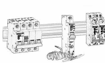
1 Ready to install Distribution boards, DIN rail mounted equipment, enclosures and connection systems
2 Contents Isobar 4 distribution boards and protective devices Section one 7 Modular control products Section two 31 Unit mounted residual current devices Section three 73 Unit mounted circuit breakers Section four 79 Connection systems Section five 113 Enclosures Section six 121 Technical data Section seven 133 Dimensions Section eight 163 Schneider Electric overview Section nine 197 Comprehensive quick reference index Section ten 203

3 Isobar 4 Type A distribution board features Fully type tested conditional short circuit rating of 16kA to BS EN High performance MCB 10kA BS kA BS in B, C or D curve single and double pole 125A busbar rating Isobar disconnection system ensuring unused outgoing ways are isolated Option of switching outgoing neutral on all boards using distributed neutral kit Terminal block for feeding up to 100A Range of incomers: switch disconnectors, residual current devices, terminal blocks Single pole RCBO for new or retrofit maintaining device density Full range of device accessories and auxiliaries Knockouts for cable gland and conduit

4 Isobar 4 Type B distribution board with 125A incomer features High performance MCB 10kA BS kA BS in B, C or D curve 1, 2, 3 and 4 pole Fully type tested conditional short circuit rating of 25kA to BS EN when fed by MCCB 250A busbar rating Isobar disconnection system ensuring unused outgoing ways are isolated Option of switching outgoing neutral using distributed neutral kit Range of incomers Removable insulated pan assembly Fully shrouded neutral Split neutral bars Removable gland plates

5 Isobar 4 Type B distribution board with 250A incomer features High performance MCB 10kA BS kA BS in B, C or D curve 1, 2, 3 or 4 pole Fully type tested conditional short circuit rating of 25kA to BS EN when fed by MCCB 250A busbar rating Isobar disconnection system ensuring unused outgoing ways are isolated Option of switching outgoing neutral using distributed neutral kit Range of incomers up to 250A Removable insulated pan assembly Fully shrouded neutral Split neutral bars Removable gland plates
6 Isobar 4 distribution boards and protective devices Section one Type A single phase Distribution boards 8-9 Incoming devices 10 Outgoing devices 21 - Loose enclosures and accessories 11 Type B three phase Distribution boards 12 Incoming devices Outgoing devices 21 - Loose enclosures and accessories 16 Replacement items Pan assemblies Type A and Type B 20 Doors and covers Type A and Type B 20 7
 ways Height Width Depth MGAN6 6 264 260 127 MGAN9 9 264 315 127 MGAN12 12 264 370 127 MGAN15 15 264 450 127 *MGAN23 23 494 370 127 * 2 row unit.")
 outgoing ways outgoing ways Height Width Depth MGAN46SL 4 6 264 450 127 MGAN48SL 4 8 264 450 127 MGAN66SL 6 6 264 450 127 MGAN66SL Specification: Designed,")
7 Isobar 4 SP&N type A distribution boards* Note: All devices are sold separately 125A Standard A boards (incomers not included) Part N o. N o. of outgoing Dimensions (mm) ways Height Width Depth MGAN MGAN MGAN MGAN *MGAN * 2 row unit. MGAN6 125A Split load A boards (incomers not included) Part N o. Unprotected Protected Dimensions (mm) outgoing ways outgoing ways Height Width Depth MGAN46SL MGAN48SL MGAN66SL MGAN66SL Specification: Designed, manufactured and tested to BS EN Unique Isobar outgoing phase connection link Busbar rating 125A Voltage rating 230/240Vac Distributed neutral allowing 2 pole switching at any outgoing way using distributed neutral kit Ingress protection IP31 to BS EN Cable capacity neutral and earth bar 25mm 2 DIN rail mounting with fully shrouded busbars Surface or flush mounting using flush mounting kit, see page 11 5 single pole blanking plates Colour RAL 9001 epoxy powder coated IP2X with covers removed Incomers: Switch disconnector see page 10 Residual current device see page 10 Terminal block see page 10 Outgoers: MCBs see page 21 RCBOs see page 2 pole Vigi see page 23 Auxiliaries see page 26 Distribution board accessories see page 11 * for use only with C60H range 8
8 Isobar 4 SP&N type A distribution boards* Note: All devices are sold separately 125A Dual incomer A boards (incomers not included) Part N o. N o. of N o. of Dimensions (mm) outgoing ways outgoing ways Circuit A Circuit B Height Width Depth MGAN46DS MGAN66DS MGAN76DS Loads should be evenly distributed across primary and secondary supplies. MGAN66DS MGAN716MS 125A Multi service A boards (incomers not included) Part N o. N o. of Useable Dimensions (mm) outgoing ways DIN rail SP way Height Width Depth MGAN416MS MGAN520MS MGAN716MS MGAN96MS MGAN912MS MGAN1010MS MGAN126MS MGAN18MS row unit. Specification: Designed, manufactured and tested to BS EN Unique Isobar outgoing phase connection link Busbar rating 125A Voltage rating 230/240Vac Distributed neutral allowing 2 pole switching at any outgoing way using distributed neutral kit Ingress protection IP31 to BS EN Cable capacity neutral and earth bar 25mm 2 DIN rail mounting with fully shrouded busbars Surface or flush mounting using flush mounting kit, see page 11 5 single pole blanking plates Colour RAL 9001 epoxy powder coated IP2X with covers removed * for use only with C60H range Incomers: Switch disconnector see page 10 Residual current device see page 10 Terminal block see page 10 Outgoers: MCBs see page 21 RCBOs see page 2 pole Vigi see page 23 Auxiliaries see page 26 Control and command devices see page 31 Distribution board accessories see page 11 9
9 Isobar 4 SP&N type A distribution boards - incomers Part N o. Rating Voltage N o. of poles MGI A 230/240V 2 BS EN ACA Cable capacity 50mm 2 Red toggle and PCI in accordance with BS 7671 Wiring Regulations Tightening torque 3.5Nm MGI1252 RMG Part N o. Rating Voltage Sensitivity RMG A 230/240V 30mA RMG A 230/240V 100mA RMG A 230/240V 300mA RMG A 230/240V 30mA RMG A 230/240V 100mA RMG A 230/240V 300mA A 230/240V 100mA Time delayed RMG A 230/240V 30mA RMG A 230/240V 100mA RMG S 100A 230/240V 100mA Time delayed RMG A 230/240V 300mA A 230/240V 300mA Time delayed Specification: BS EN Positive contact indication in accordance with BS 7671 Cable capacity 63A, 80A = up to 35mm 2 100A = up to 50mm 2 Terminal tightening torque 2Nm (35mm 2 ), 3.5Nm (50mm 2 ) Part N o. Rating Voltage N o. of poles MGTB A 230/240V 2 Specification: Direct connection incoming lug unit, two pole suitable for use in any Isobar 4 A type board Cable capacity 50mm 2 Terminal tightening torque 3.5Nm MGTB
10 MGN56DE Application A range of steel enclosures using the Isobar 4 A board design suitable for mounting DIN devices including MCBs, RCBOs and control and command products. Part Useable N o. of Dimensions (mm) N o. DIN rail rows SP ways Height Width Depth MGN16DE MGNDE MGN28DE MGN34DE *MGN56DE * 2 row unit. Specification: Folded sheet steel enclosure Ingress protection IP31 to BS EN DIN rail Colour RAL 9001 epoxy powder coated Surface or flush mounting using flush mounting kit Earth bar 5 single pole blanking plates Accessories: Part N o. Description MGBL Key lock BP Blanking plates 5 off light grey Isobar 4 MGA loose enclosures and board accessories Part N o. SP circuits Description MGANWL 15 A board spare outgoing way self adhesive labels MGANWL MGTB1001 Part N o. MGTB1001 Description 100A terminal block for installation in Isobar boards as an outgoing way. Supplied with identification labels. Note: cable must be provided with local protection to comply with BS Cable capacity 50mm 2. Part N o. MGNA4 MGNA6 MGNA7 MGNA9 MGNA12 MGNA15 Description Distributed neutral kit for 4 way SP+N Distributed neutral kit for 6 way SP+N Distributed neutral kit for 7 way SP+N Distributed neutral kit for 9 way SP+N Distributed neutral kit for 12 way SP+N Distributed neutral kit for 15 way SP+N MGNA24 Distributed neutral kit for 24 way SP+N NKIT Phase to neutral conversion kit (pack 4) Note: One pack included in a distributed neutral kit MGACE Part N o. MGACE Flush mounting kit Part N o. MGAN6FK MGAN9FK MGAN12FK MGAN15FK MGAN24FK Description Clean earth facility for A type boards (6 hole). Or can be used to comply with BS where the protective conductor ring shall be separately connected at the distribution board. For use with MGAN6, MGN16DE MGAN9 MGAN12, MGAN46DS, MGAN416MS MGAN15, MGAN46SL, MGAN48SL, MGAN66SL, MGAN76DS, MGAN912MS, MGAN1010MS, MGAN18MS MGAN23, MGAN18MS 11
 outgoing ways Height Width Depth MGBN4 4 484 470 158 MGBN6 6 484 470 158 MGBN8 8 538 470 158 MGBN12 12 700 470 158 MGBN16 16 808 470 158 MGBN18 18 808 470 158 MGBN24 24 970")


11 Isobar 4 TP&N type B distribution boards* Note: All devices are sold separately Standard B boards Part N o. N o. of TP Dimensions (mm) outgoing ways Height Width Depth MGBN MGBN MGBN MGBN MGBN MGBN MGBN MGBN12 Split load B boards These are achieved by selecting any 2 Isobar B boards and joining with either MGBNTJKN and feeding the top board via a outgoing 100 amp terminal block MGTB1001 for each phase or use MGBN63SPL split load kit which is supplied with a 63 amp C curve mcb Multi service B boards Control products can be added to any B type distribution board using a modular extension box MGBNEX034N which will accept 17 single pole wide control products MGBN12+MGBN8 Specification: Designed, manufactured and tested to BS EN Unique Isobar outgoing phase connection link Busbar rating 250A Voltage rating 400/415Vac Distributed neutral allowing 2 or 4 pole switching at any outgoing way using distributed neutral kit Ingress protection IP31 to BS EN Cable capacity neutral and earth bar 25mm 2 100% rated DIN rail mounting with fully shrouded busbars Surface mounting Flush mounting available 5 single pole blanking plates supplied Colour RAL 9001 epoxy powder coated IP2X with covers removed Incomers: see page 14 Outgoers: see page 21 MGBN8 + Multi service * for use only with C60H range 12

12 Isobar 4 TP&N type B distribution boards* Note: All devices are sold separately Heavy duty IP55 (125A) Part N o. N o. of outgoing Height Width Depth ways TP MGBN6HDGK MGBN8HDGK MGBN12HDGK MGBN16HDGK MGBN12HDGK Specification: Designed, manufactured and tested to BS EN Unique Isobar outgoing phase connection link Busbar ratings 125A Voltage rating 400/415Vac Distributed neutral allowing 2 or 4 pole switching at any outgoing way using distributed neutral kit Ingress protection IP55 to BS EN Cable capacity neutral and earth bar 25mm 2 DIN rail mounting with fully shrouded busbars Additional earth stud provided 5 single pole blanking plates Colour RAL 9001 epoxy powder coated Door can be left or right handed Key lockable enclosure as standard Incomers: Switch disconnector see page 15 Residual current devices see page 15 Terminal blocks see page 15 (Maximum 125A DIN rail mounted) Outgoers: MCBs see page 21 RCBOs see page 23 * for use only with C60H range 13
13 Isobar 4 TP&N type B distribution boards - incomers Switch disconnectors Part N o. Rating Voltage N o. of poles MGI1253N 125A 415V 3 + N MGI A 415V 4 MGI1254 Specification: BS EN Category of duty AC Positive contact indication in accordance with BS 7671 Cable capacity 50mm 2 Terminal tightening torque 3.5Nm Lockable in ON or OFF position using ref: MGLA MGNI2504 Switch disconnectors ( A) Part N o. Rating Voltage N o. of poles MGNI A 415V 3+N MGNI A 415V 3+N MGNI A 415V 3+N MGNI A 415V 4 MGNI A 415V 4 MGNI54 5A 415V 4 MGNI A 415V Bare cable connector set 95mm 2 160A set of Bare cable connector set 185mm 2 250A set of 4 MGALK Allen key kit for fitting devices >160A Devices fit directly into distribution board and are supplied with 270mm extension box. Specification: BS EN Copper pad for M8 lugs, tightening torque 15Nm Lockable in ON or OFF position Category of duty AC Positive contact indication in accordance with BS 7671 MGBNI160RCCB Residual current circuit breakers (RCCBS A) Part N o. Rating Voltage Sensitivity N o. RMG A 415V 30mA 4 RMG A 415V 100mA 4 RMG A 415V 300mA A 415V 300mA TD** A 415V 30mA A 415V 300mA A 415V 300mA TD** 4 MGNI160RCCB* 160A 415V Adjustable 4 * Item is supplied with 270mm extension box, MCCB and Vigi. ** Time delay as an element of discrimination. Specification: BS EN Positive contact indication in accordance with BS 7671 Lockable in ON or OFF position Trip free mechanism Cable capacity 63A/80A - 35mm 2, 100A - 50mm 2 Terminal tightening torque 2Nm (63/80A), 3.5Nm (100A), 15Nm (160A) of poles 14
14 Isobar 4 TP&N type B distribution boards - incomers Terminal blocks (125/250A) Part N o. Rating Voltage Notes MGTB A 415V MGNTB A 415V With extension box MGNPBN250TB 250A 415V Without extension box Specification: Cable capacity: 125A - 50mm 2 250A - M8 copper pad Terminal tightening torque: 125A - 3.5Nm 250A - 15Nm MGTB1254 Moulded case circuit breakers (MCCBs A) Part N o. Rating Voltage N o. of poles MGNCB A 415V 4 MGNCB A 415V 4 MGNCB A 415V 4 MGNCB A 415V 4 MGALK Allen key kit for fitting devices >160A MGNCB2004 Devices fit directly into distribution board and are supplied with 270mm extension box and terminal shield Can be fitted with shunt trip, UVR and auxiliary switch. Refer to Compact NS Catalogue Distribution boards fitted with a MCCB are suitable for installations with fault levels up to 25kA Specification: BS EN Category of duty AC Positive contact indication in accordance with BS 7671 Cable capacity 50mm 2-185mm 2 Terminal tightening torque 100A - 10Nm, 160, 200 and 250A - 15Nm Surge arrestor kit Part N o. Description MGNPRD Supplied with extension box and protection device Dual source incomer Part N o. Rating Voltage N o. of poles MGNDSI 125A 415V 4 MGNDSI To be used in dual source applications, with standby being a portable/fixed generator set or second transformer. Mechanically interlocks any combination of the following incoming 4P devices: MGI1254 C120 To be ordered separately. } C60 A padlocking facility enables either one or both to be locked in the OFF position or using MGLA for locking ON. Front cover is lockable using MGBL. Cable capacity 50mm 2. Supplied complete with board connection. 15

 18mm rows SP ways Height Width Depth MGBN4SXS 34 2 484 470 158 MGBN8SXS 34 2 538 470 158 MGBN12SXS 51 3 700 470 158 MGBN16SXS 68 4 808 470 158 MGBN24SXS 85 5 970 470 158 Supplied")
15 Isobar 4 MGB loose enclosures Application MGB loose enclosures are designed to accommodate DIN rail mounted products, primarily for control and metering. They may be mounted individually or attached to the side of an MGB board of equivalent height using the side joining kit MGBNSJK. Alternatively they may be attached to the top or bottom of an MGB board using the top/bottom joining kit MGBNTJKN. MGBN8SXS Supplied with DIN rail, door and slotted front cover Part N o. N o. of N o. of Dimensions (mm) 18mm rows SP ways Height Width Depth MGBN4SXS MGBN8SXS MGBN12SXS MGBN16SXS MGBN24SXS Supplied with DIN rail, door and plain front cover Part N o. N o. of N o. of Dimensions (mm) 18mm rows SP ways Height Width Depth MGBN4SXP MGBN8SXP MGBN12SXP MGBN16SXP MGBN24SXP MGBN8SXP Specification: Ingress protection IP31 to BS EN Earth bar capacity 25mm 2 Surface or flush mounting using flush mounting kit, see page 28 Colour RAL 9001 epoxy powder coated For enclosure accessories see page 18 For alternative enclosures see Section six, page 121. Extra terminal bar for earth For inside enclosure mounting Including support Current rating 200A 25mm 2 holes Type Part N o. For panel mounting 12 holes MG12EE 18 holes MG18EE 24 holes MG24EE 36 holes MG36EE 48 holes MG48EE 56 holes MG56EE 72 holes MG72EE 16


 Switch disconnector Extension box 270mm Interconnections 100A terminal block 3 phase kwh metering Part N o.")
16 Isobar 4 B board extension boxes and metering Application The range of B boards are manufactured in a 270mm modular height thereof, to allow the user greater flexibility, so enabling the inclusion of single phase distribution boards, multi service units, larger cabling arrangements etc. MGBNEXN Part N o. MGBNEXN Part N o. MGBNEX034N Description Extension box with plain front cover. Provides additional wiring space or a housing for control or metering equipment. Description Extension box with DIN rail, slotted front cover and door. Provides space for up to 17 SP DIN mounted products. Includes gland plate and joining kit. MGBNEX034N Part N o. MGBNEXA15N Description A 15 way Isobar 4c A type distribution board designed for fixing direct on to any Isobar 4c B type board. MGBNEXA15N MGBN100CCI Contactor incomer 100A Part N o. Description MGBN100CCI Provides contactor control and isolation of Isobar 4c B type boards Kit includes 100A contactor 240Vac coil (Part No , see page 46 for details) Switch disconnector Extension box 270mm Interconnections 100A terminal block 3 phase kwh metering Part N o. MGBNKWH Description Extension box with multi-function meter, CT s, wiring loom and MCB to pick up voltage. Meter provides Phase voltage kvarh Current Power factor kwh, kw per phase Pulsed output per kwh MGBNKWH Note: Voltage connection takes up 4 SP outgoing ways at bottom of stack 17

17 Isobar 4 TP&N type B distribution board accessories Part N o. Description SP circuits MGBNWL B board front cover way labels 72 MGBNWL 100A outgoing terminal block Part N o. MGTB1001 Description 100A terminal block for installation in Isobar boards as an outgoing way. Supplied with identification labels. Note: cable must be provided with local protection to comply with BS Cable capacity 50mm 2. MGBL Part N o. MGBL MGK33 Description Door lock for A and B boards new style square sliding catch 2 off spare keys for MGBL Spare door catch Part N o. Description BP 5 pole blanking plates (light grey). Note: 1 off BP supplied with each distribution board. BP Part N o. MGBNGPN MGBNGPEXN Description Gland plate plain for B type distribution board Gland plate for Isobar extension box Gland plate for B board with knock out 18

18 Isobar 4 TP&N type B distribution board accessories Single phasing kit (125/250A) Part N o. Rating Voltage Description MG125SPEV 125A 415V For 4P incomers up to 125A MG250SPEV 250A 415V For 4P incomers up to 250A Converts a TP&N B board incomer into single phase applications when used in conjunction with the above terminal blocks and switch disconnectors. MG125SPEV MG250SPEV Part N o. MGBNTJKN MGBNSJK MGBN63SPL Description Joining kit for two type B distribution boards mounted above or below each other. Joining kit for two type B distribution boards mounted side by side. 63amp split load kit kit. MGBNSJK Part N o. MGNB4 MGNB6 MGNB8 MGNB12 MGNB16 MGNB18 MGNB24 Description Distributed neutral kit for 4 way TP+N Distributed neutral kit for 6 way TP+N Distributed neutral kit for 8 way TP+N Distributed neutral kit for 12 way TP+N Distributed neutral kit for 16 way TP+N Distributed neutral kit for 18 way TP+N Distributed neutral kit for 24 way TP+N NKIT Phase to neutral conversion kit (pack 4) Note: One pack included in a distributed neutral kit MGNB6 Part N o. MGNBCE7 MGNBCE25 Description for type B boards provides 7 clean earth or extra neutral/earth holes. 25 hole Clean earth facility 19


19 Isobar 4 Replacement pan assemblies, doors and covers A board pan assembly* Part N o. MGAN6P MGAN9P MGAN12P MGAN15P Description 6 way SP&N pan assembly 9 way SP&N pan assembly 12 way SP&N pan assembly 15 way SP&N pan assembly MGAN9P B board pan assembly Part N o. MGBN4P MGBN6P MGBN8P MGBN12P MGBN16P MGBN418P MGBN24P Description 4 way TP&N pan assembly 6 way TP&N pan assembly 8 way TP&N pan assembly 12 way TP&N pan assembly 16 way TP&N pan assembly 18 way TP&N pan assembly 24 way TP&N pan assembly MGBN8P A board door and cover Part N o. MGAN6C MGAN9C MGAN12C MGAN15C MGAN23C Description Suitable for MGAN6 Suitable for MGAN9 Suitable for MGAN12 Suitable for MGAN15 Suitable for MGAN23 MGAN6C B board door and cover Part N o. MGBN4C MGBN6C MGBN8C MGBN12C MGBN16C MGBN18C MGBN24C Description Suitable for MGBN4 Suitable for MGBN6 Suitable for MGBN8 Suitable for MGBN12 Suitable for MGBN16 Suitable for MGBN18 Suitable for MGBN24 MGBN8C * for use only with C60H range 20

20 C60H Isobar 4 outgoers miniature circuit breakers 1-63A Installation In Merlin Gerin Isobar 4 distribution boards Symmetrical DIN rail Direct panel mounting Isobar 4 pan assemblies 1, 2, 3 and 4 pole Type B Miniature circuit breakers Technical data Current ratings: 1-63A at 30 0 C to BS EN Voltage ratings: Vac Breaking capacity: BS EN 60898: 10kA, BS EN : 15kA See page 140 for further information on breaking capacities and dc ratings. Operating cycles (O-C): on load 20,000 Operating temperature: C to C Positive contact indication: in accordance with BS 7671 Current limitation: Class 3 Width: Pole 18mm SP ways mm Dimensions: see page 172 Weight: Pole Grams Accessories: see page 26 Add on earth leakage: see page 23 Technical data: see page 133 1, 2, 3 and 4 pole Type C Miniature circuit breakers Note: 2 and 4 pole C60H MCBs are suitable for installation in Isobar 4 distribution boards and pan assemblies with NKIT. For current ratings greater than 63A, see Section four. Note: Not suitable as outgoing way in Isobar 4c. See page 135 for grouping factor 1, 2 and 3 pole Type D Miniature circuit breakers 21
21 C60H Isobar 4 outgoers miniature circuit breakers 1-63A C60HB type B (3-5In) Applications Protection and control of circuits against overloads and short circuits. In applications with general load characteristics Tripping characteristics: BS EN type B: magnetic setting between 3 and 5 In Cable capacity: 1-25A = 25mm A = 35mm 2 Tightening torque: 25A = 2.5Nm 32-63A = 3.5Nm C60HB miniature circuit breaker Part N o s Ratings 1P 2P 3P 4P (A) 1 C60HB 101 C60HB 201 C60HB 301 C60HB C60HB 102 C60HB 202 C60HB 302 C60HB C60HB 104 C60HB 204 C60HB 304 C60HB C60HB 106 C60HB 206 C60HB 306 C60HB C60HB 110 C60HB 210 C60HB 310 C60HB C60HB 116 C60HB 216 C60HB 316 C60HB C60HB 120 C60HB 0 C60HB 320 C60HB C60HB 125 C60HB 5 C60HB 325 C60HB C60HB 132 C60HB 232 C60HB 332 C60HB C60HB 140 C60HB 240 C60HB 340 C60HB C60HB 150 C60HB 250 C60HB 350 C60HB C60HB 163 C60HB 263 C60HB 363 C60HB 463 C60HC type C (5-10In) Applications Protection and control of circuits against overloads and short circuits. In applications with moderate inrush currents, such as certain lighting systems Tripping characteristics: BS EN type C: magnetic setting between 5 and 10 In Cable capacity: 1-25A = 25mm A = 35mm 2 Tightening torque: 25A = 2.5Nm 32-63A = 3.5Nm C60HC miniature circuit breaker Part N o s Ratings 1P 2P 3P 4P (A) 1 C60HC 101 C60HC 201 C60HC C60HC 102 C60HC 202 C60HC C60HC 104 C60HC 204 C60HC C60HC 106 C60HC 206 C60HC C60HC 110 C60HC 210 C60HC C60HC 116 C60HC 216 C60HC C60HC 120 C60HC 0 C60HC C60HC 125 C60HC 5 C60HC C60HC 132 C60HC 232 C60HC C60HC 140 C60HC 240 C60HC C60HC 150 C60HC 250 C60HC C60HC 163 C60HC 263 C60HC C60HD type D (10-14In) Applications Protection and control of circuits against overloads and short circuits. In applications with high inrush currents, such as transformers, motors, certain lighting systems etc Tripping characteristics: BS EN type D: magnetic setting between 10 and 14 In Cable capacity: 1-25A = 25mm A = 35mm 2 Tightening torque: 25A = 2.5Nm 32-63A = 3.5Nm C60HD miniature circuit breakers Part N o s Ratings 1P 2P 3P 4P (A) 1 C60HD 101 C60HD 201 C60HD C60HD 102 C60HD 202 C60HD C60HD 104 C60HD 204 C60HD C60HD 106 C60HD 206 C60HD C60HD 110 C60HD 210 C60HD C60HD 116 C60HD 216 C60HD C60HD 120 C60HD 0 C60HD C60HD 125 C60HD 5 C60HD C60HD 132 C60HD 232 C60HD C60HD 140 C60HD 240 C60HD C60HD 150 C60HD 250 C60HD C60HD 163 C60HD 263 C60HD

22 Vigi C60 Add on residual current device for use with C60 MCBs only + = Applications Clipped onto the side of any C60 MCB, add on Vigis provide a high level of protection against earth fault in addition to overload and short circuit protection provided by the MCB alone. Effectively creating an RCBO to BS EN 61009, C60 MCBs with add on Vigis can be used with any Isobar 4 distribution board, pan assemblies as well as a wide range of DIN enclosures. MCB 2P Vigi RCBO Vigi modules - 2 pole for assembly with 1 or 2 pole MCBs Part N o. Ratings Sensitivity Width in (A) (ma) 18mm SP ways MGV MGV MGV MGV T Vigi modules - 4 pole for assembly with 3 or 4 pole MCBs Part N o. Ratings Sensitivity Width in (A) (ma) 18mm SP ways MGV MGV Terminal screw shields available for Vigi RCDs. See C60 accessories on page T Specification: Standards Approval: BS EN (BS EN when fitted to MCB) Operating voltage: 2 pole = 110/240V, 50/60Hz, 4 pole = 240/415V, 50/60Hz Cable capacity: 2 pole = 25mm 2, 4 pole = 35mm 2 Tightening torque: 2.5Nm = 25mm 2, 3.5Nm = 35mm 2 Class AC Integral self test button Indication of earth fault trip Note: Must not be used as the sole means of protection against direct contact with live parts (BS 7671). Dimensions: see page
 Protection against insulation faults Finger safe terminals Reverse polarity")
23 C60H RCBO (18mm) Combined MCB/RCD Applications Protection against overloads, short circuits and earth leakage faults. The C60H RCBO provides: Protection against indirect contact Supplementary protection against direct contact (BS 7671) Protection against insulation faults Finger safe terminals Reverse polarity protection Loss of neutral and earth protection Operating voltage: 200Vac - 230Vac Current ratings: 6A - 45A Tripping characteristics: BS EN (type C) magnetic setting between 5-10 In Breaking capacity: BS EN ,000A, BS EN kA Class 3 current limiting overcurrent protection Positive contact indication in accordance with BS 7671 Lockable in ON or OFF position using MGLA Trip free mechanism Compatible with C60 auxiliaries and accessories e.g. alarm contact, shunt trip Load terminals cable capacity 16mm 2 Dimensions: see page 172 C60HC32R30 Trip sensitivity AC class Tripped by sinusoidal AC currents independent of rate of rise. A class Tripped by sinusoidal AC pulsed DC and those containing DC component. Installation Isobar 4 distribution boards, pan assemblies and standard enclosures on symmetrical DIN rail Part N o. Ratings Curve Class (A) type C60HC6R30 6A 30mA C AC C60HC10R30 10A 30mA C AC C60HC16R30 16A 30mA C AC C60HC20R30 20A 30mA C AC C60HC32R30 32A 30mA C AC C60HC45R30 45A 30mA C AC C60HC6R100 6A 100mA C AC C60HC10R100 10A 100mA C AC C60HC16R100 16A 100mA C AC C60HC20R100 20A 100mA C AC C60HC32R100 32A 100mA C AC C60HC45R100 45A 100mA C AC C60HC6RA10 6A 10mA C A C60HC10RA10 10A 10mA C A C60HC16RA10 16A 10mA C A C60HC20RA10 20A 10mA C A C60HC32RA10 32A 10mA C A C60HC45RA10 45A 10mA C A C60HC6RA30 6A 30mA C A C60HC10RA30 10A 30mA C A C60HC16RA30 16A 30mA C A C60HC20RA30 20A 30mA C A C60HC32RA30 32A 30mA C A C60HC45RA30 45A 30mA C A 24
24 Electrical auxiliaries C60 MCBs and RCBOs Applications For the remote control and status indication of C60 MCBs. They are mounted to the left of the circuit breaker within a maximum width of 54mm Fixed using clips (no tools) onto the left side of the circuit breaker Compatible with Vigi modules (fitted to the right side) A maximum of 3 indication auxiliaries on the same circuit breaker A maximum of 2 changeover auxiliaries (OF+SD/OF) on the same circuit breaker A maximum of 2 tripping auxiliaries (MX + OF or MN) on the same circuit breaker A maximum of 1 tripping auxiliary (MN s or MNx or MSU) on the same circuit breaker Auxiliary combination OF+SD/OF auxiliary contact OF auxiliary contact SD fault indication switch Mx + OF, MN, MN s MNx or MSU auxiliary Circuit breaker 25
25 Electrical auxiliaries C60 MCBs and RCBOs MX + OF (shunt release and auxiliary contact) Control Part N o. Width in voltage 18mm SP (Vac) (Vdc) ways U> /24 12/ Disconnects the MCB when a voltage is applied. Indication of tripping and fitted with changeover contact for indication. Self breaks control circuit allowing it to remain energised C2 C1 MSU (voltage threshold release) 1P + N Control Part N o. Width in voltage 18mm SP (Vac) ways U>> tripping at 255V tripping at 275V N L MN (under voltage release) Instantaneous Control Part N o. Width in voltage 18mm SP (Vac) (Vdc) ways U< (400Hz) Delayed s Disconnects the MCB when a voltage is removed. D1 D MNx emergency stop U> E1 E2 N L Control Part N o. Width in voltage 18mm SP (Vac) ways * * * For use with C60 only. Disconnects the MCB when the normally closed push button contact is opened. Does not trip in the event of power supply failure. MX shunt release U> Control Part N o. Width in voltage 18mm SP (Vac) (Vdc) ways /24 12/ C2 C1 26
26 Electrical auxiliaries C60 MCBs and RCBOs SD fault indicating switch OF auxiliary contact OF + SD/OF selector switch Part N o. Width in 18mm SP ways Contact rating (V) (A) 240Vac 6A Auxiliary contact 415Vac 3A changes when device 24Vdc 6A trips with front face 48Vdc 2A indication, red for 125Vdc 1A tripped. Part N o. Width in 18mm SP ways Contact rating (V) (A) 240Vac 6A Auxiliary contact 415Vac 3A changes with main 24Vdc 6A contacts (on/off) with 48Vdc 2A test button on front 125Vdc 1A face. Part N o. Width in 18mm SP ways Auxiliary contact and selectable auxiliary or fault contact with front face indication. Note: Does not fit onto Isobar 4 distribution board. 27
27 Accessories For C60 Padlocking facility Breaker Quantity Part N o. C60 Pack of 5 MGLA MGLA Note: MGLA is suitable for use with C60 MCBs/RCBOs mounted in Isobar 4 distribution boards. Description Part N o. Padlock 4mm hasp for MGLA MGLAP For MCBs/RCDs (pack of 2) Screw shield Breaker Quantity Part N o. C60 Sealable and dividable 2 x strips of Screw shield Breaker Quantity Part N o. C60 Vigi Sealable 1P shields 20 off Terminal shield Breaker Pole Part N o. C60 pair /26976 Insulated sub distribution terminal For 3 x cables up to 16mm 2 each Breaker Quantity Part N o. C60>25A Pack of *Aluminium cable terminal For cables of 16-50mm 2 Breaker Quantity Part N o. C60>25A Pack of * not for use in Isobar 4 distribution boards 28
28 Accessories For C60 *Rear connection terminal For cables up to 50mm 2. Breaker Quantity Part N o. C60 Pack of * not for use in Isobar 4 distribution boards Inter-pole barrier Breaker Quantity Part N o. C60 Pack of
29 Accessories For C60 Spacer Breaker Width Part N o. C60 9mm Replacement cover for vigibloc Breaker Pole Part N o. C Pack of replacements
30 Modular control products Section two Local control Remote control Time management Lighting management Metering and measurement Heating management 71 31
31 I switch disconnectors A Application The I switches perform the operations of control and disconnection. Technical details Compliance with standards: I 20, 32 and 40A: BS EN , IEC I 63, 100 and 125A, IEC Degree of pollution 3 - Isolating voltage 500Vac - Impulse voltage 6kV - Degree of protection IP4X on the front panel - Frequency 50-60Hz Isolation with positive contact indication DC application: 48V (110V with 2 series connected poles) Mechanical endurance: I 20, 32 and 40A: 200,000 operating cycles I 63, 100A and 125A: 50,000 operating cycles Electrical endurance: AC, p.f. = 0.6: I = 20 and 32A:30,000 operating cycles I = 40 and 63A: 20,000 operating cycles I = 100A: 10,000 operating cycles I = 125A: 2,500 operating cycles Short circuit withstand: 20 x In: 1s Tropicalisation: treatment 2 (relative humidity 95% at 55 C) Connection by tunnel terminals for: 10mm_ flexible/rigid cables for I 20-40A 50mm_ rigid cables or comb busbars, 35mm 2 supple cables for I 63, 100 and 125A Tightening torque: 20A = 1.4Nm 32-40A = 2Nm A = 3.5Nm Auxiliary O.C auxiliary switch Contact breaking capacity: 3A at 400Vac 6A at 230Vac Fixing by clipping onto symmetrical rail, on the left side of the switch Connection by tunnel terminals for 2 x 2.5mm cables Type Rating Voltage Width Part N o. (A) (Vac) in 18mm SP ways I switches P I switches P + indicator x1 2 x2 32
32 I switch disconnectors A Type Rating Voltage Width Part N o. (A) (Vac) in 18mm SP ways I switches P I switches P + indicator x1 2 4 x2 Type Rating Voltage Width Part N o. (A) (Vac) in 18mm SP ways I switches P Type Rating Voltage Width Part N o. (A) (Vac) in 18mm SP ways I switches P Type Rating Voltage Width Part N o. (A) (Vac) in 18mm SP ways Accessories NO auxiliary 3 (6) 415 (230) Terminal shields
33 TR transformers 4-63VA Application Safety and bell transformers allow for a very low voltage to be obtained from a 230Vac supply. Technical details Primary voltage: 230Vac ± 10% Secondary voltage on load: Vac ± 15% for bell transformers 12-24Vac ± 5% for safety transformers Frequency: 50Hz - 60Hz Compliance with standards: EN , IEC Connection tunnel terminals for cables up to 4mm 2 Type Power Secondary Width Part N o. (VA) voltage in 18mm (Vac) SP ways Bell transformer Safety transformer V V V V 11 8V V V V 8 12V , 15213, V 24V , V V V 12V 15218, ,
34 RO buzzer and SO bell Audible signalling Application Audible indication of signals. Technical details Sound level (at distance of 60 cm): RO buzzer: 70dB SO bell: 80dB Frequency: 50-60Hz Consumption: 3.6VA:8-12A 5VA: 0-240V Connection: tunnel terminals for cables up to 4mm 2 Type Secondary Sound Width Part N o. voltage level in 18mm (V) (db) SP ways Bell Buzzer SO bell RO buzzer 35
35 STI fuse carriers Withdrawable gl or gg fuse links Application STI fuse carriers provide overload and short circuit protection. Technical details Carrier Isolation of all poles is guaranteed for the 2P and 3P versions during factory assemble Positive contact indication To be equipped with gg (gl - gl) type fuse links, with or without fuse blowing indicator Fuse carrier: Captive Additional housing is provided for a spare fuse Optional indication: by indicator lights (see accessories) Connection: by tunnel terminals for rigid cables up to 10mm 2 and flexible cables up to 6mm 2 Complies with standard: IEC Fuse link gg (gl - gl) types. Fuse link without striker pin Breaking capacity: as standard IEC 269-1/2 Vertitas and Lloyd s approved Dimensions Rating Operating Breaking (Ø x L) (A) voltage capacity (mm) (Vac) (ka) gg (gl - gl) 10 x Type Voltage Width Part N o. (Vac) in 18mm ways 1P P+N P P P+N Type Rating Dimensions Part N o. (A) (mm) gg (gl) fuse links x x x x Blown fuse indicator
36 PRD surge arresters Draw out Application PRD removable surge arresters enable the rapid replacement of damaged cartridges without any cable disconnection Technical details* Each surge arrester in the range has a specific use: Incomer and protection: PRD 40r/PRD 40 are recommended for a high risk level The PRD 15 is recommended for a low risk level Secondary protection: The PRD 8 ensures secondary protection of loads to be protected and is placed in a cascading configuration with surge arresters at the incomer end Common technical data Operation indication by means of a mechanical indicator: White: normal operation Disconnection of the short circuited surge arrester to be conducted with a circuit breaker Recommended breaker: Single phase + N: C60HC0 Three phase + N: Standards IEC class 2 test PRD 40r/PRD 40 Imax (8/20µs): 40kA In (8/20µs): 15kA The PRD 4 0r includes: Operating indicator on front panel PRD 15 Imax (8/20µs): 40kA In (8/20µs): 15kA PRD 8 Imax (8/20µs): 40kA In (8/20µs): 15kA Spare cartridges 40, 15, 8 ka and neutral cartridges The C40r and C neutral r cartridges have operating indicator L N PRD 1P+N L3 L2 L1 N Type Un Uc (V) Up Width Part N o. (V) MC MD (kv) in 18mm SP ways PRD65r 1P+N PRD65r 3P PRD65r 3P+N PRD40r 1P+N PRD40r 3P PRD40r 3P+N PRD40 1P+N PRD40 3P PRD40 3P+N PRD15 1P+N PRD15 3P PRD15 3P+N PRD8 1P+N PRD8 3P PRD8 3P+N PRD 3P+N Replacement cartridges C65r C65r C40r C40r C C C C C C C neutral r C neutral Isobar installation kit MGNPRD * Further details of surge arrester selection can be found on pages at the rear of the document. Or in publication Ref: MGD
37 PF surge arresters Fixed Application The PF all contained, multiple pole surge arrester range is especially adapted to TT and TN-s earthing systems Technical details* Each surge arrester in the range has a specific use: Incomer and protection: PF30r/PF30 are recommended for a high risk level The PF 15 is recommended for a low risk level Secondary protection: The PF 8 ensures secondary protection of loads to be protected and is placed in a cascading configuration with surge arresters at the incomer end Common technical data Operation indication by means of a mechanical indicator: Not illuminated: OK Flashing: surge arrester must be immediately replaced Disconnection upon thermal overload built into the surge arrester Disconnection of the short circuited surge arrester to be conducted with a circuit breaker: Single phase + N: C60HC0 Three phase + N: PF 30r and PF 30 Common mode protection Imax (8/20µs): 30kA In (8/20µs): 10kA Up: 1.8kV Test button for front panel indicator. The PF30r has a built-in remote indication contact: Normally closed PF 15 Common mode protection Imax (8/20µs): 15kA In (8/20µs): 5kA Up: 1.8kV Differential mode protection Imax (8/20µs): 8kA In (8/20µs): 2kA Up: 1kV PF 8 Common mode protection Imax (8/20µs): 8kA In (8/20µs): 2kA Up: 1.5kV Differential mode protection Imax (8/20µs): 8kA In (8/20µs): 2kA Up: 1kV Type Un Uc (V) Up Width Part N o. (V) MC MD (kv) in 18mm SP ways PRD65r 1P+N PRD65r 3P+N PRD30r 1P+N PRD30r 3P+N PRD30 1P+N PRD30 3P+N PRD15 1P+N PRD15 3P+N PRD8 1P+N PRD8 3P+N L1 N L3 L2 L1 N N L1 N L1 L2 L3 PF 1P+N PF 3P+N * Further details of surge arrester selection can be found on pages at the rear of the document. Or in publication Ref: MGD
38 CM selector switches Local control Application CM selector switches allow the manual switching of circuits. Technical details Voltage rating: 250Vac Current rating: 20A Electrical durability: 30,000 cycles AC Complies with standard: IEC and IEC Operating temperature: -20 C to +50 C Storage temperature: -40 C to +80 C Tropicalisation: treatment 2 (relative humidity 95% at 55 C) Connection by rigid or flexible cable with or without cable end: Tunnel terminals up to 2 x 2.5mm 2, +/- recess screw, Pozidrive n 1 Staggered terminals simplifying cable connection 2 position selector switches 0 I I I changeover switch 2 changeover switches 1NO + NC 3 position selector switches I 0 II 2 4 I 0 II changeover switch 2 changeover switches Type Circuit Width Part N o. in 18mm ways 2 position 1 changeover changeover NO+1NC position 1 changeover changeover
39 BP pushbuttons Local control Application The BP pushbuttons are used to give manual impulse signals. Technical details Voltage rating: 250Vac Current rating: 20A Electrical durability: switching operations AC (cosø = 0.8) Complies with standard: IEC and IEC Indicator light with LED technology: Consumption: 0.3 W Service life: 100,000 hours with constant luminous efficiency Indicator light requires no maintenance (non-interchangeable LEDs) Operating temperature: -20 C to +50 C Storage temperature: -40 C to +80 C Tropicalisation: treatment 2 (relative humidity: 95% at 55 C) Connection by rigid or flexible cable with or without cable end: Tunnel terminals up to 2 x 2.5mm 2 +/- recess screw, Pozidrive n 1 Staggered terminals simplifying cable connection BP NC 1 NO 1 NO+1 NC 1 NO/1 NC 1 NO/1 NC BP with indicator light 1 x1 3 x1 2 x2 4 x2 1 NO 1 NC Type Indicator Pushbutton Indicator Circuit Width Part N o. colour colour voltage in 18mm ways Single Grey 1NC Red 1NC Grey 1NO Double Grey 1NO+1NC Grey/Red 1NO+1NC Grey/Grey 1NO+1NC Pushbutton with Green Grey Vac 1NO indicator Red Grey Vac 1NC Green Grey 12-48Vac/dc 1NO Red Grey 12-48Vac/dc 1NC
40 V indicator lights Local control 126 Application The V indicator lights provide visual indication and signalling. Technical details Complies with standard IEC (except part number 127 complies with standard IEC 73 and IEC ) Operating frequency: 50-60Hz Indicator light with LED technology Consumption: 0.3 W (0.5 W for Part N o. 127) Service life: 100,000 hours with constant luminous efficiency Indicator light requires no maintenance (non-interchangeable LEDs) Flashing frequency: 2Hz (126) Degree of protection: IP4X for the part outside the enclosure IP2X at the terminals Divisible partition to accommodate a comb busbar Operating temperature: -20 C to +50 C Storage temperature: -40 C to +100 C Tropicalisation: treatment 2 (relative humidity 95% at 55 C) Connection by rigid or flexible cable with or without cable end: Tunnel terminals up to 2 x 2.5mm 2, +/- recess screw, Pozidrive n 1 Staggered terminals simplifying cable connection x1- x1 x3 = = = x1 x1 x2 x3 230Vac x2+ x2 x4 x2 XC (N)* Single indicator light Double indicator light Flashing Three phase indicator light Type Colour Voltage Width Part N o. in 18mm ways Single indicator Red Vac light Green Vac White Vac 1 1 Blue Vac Yellow Vac Red 12-48Vac/dc Green 12-48Vac/dc White 12-48Vac/dc Blue 12-48Vac/dc Yellow 12-48Vac/dc Double indicator Green/Red Vac light Flashing indicator Red Vac light Three phase indicator Red/Red/Red Vac light 41
41 XB device holder Local control Application The device holders can be mounted on 35mm rail to facilitate mounting of pushbuttons, indicators or other devices*. Technical details Button holder For buttons, switches and indicators with metal or plastic flange Ø of the Telemecanique XB4 / XB5 type* Depth under rail 60mm (same as products in the multi 9 range) Drilling diameter: Ø.3 Self-extinguishing insulating material Colour: light grey RAL 7035 Universal holder For buttons, indicators, light emitting diodes (LED), potentiometers Easy drilling, to be adapted depending on use Depth under rail 60 mm (same as products in the multi 9 range) Self extinguishing insulating material Colour: light grey RAL Type Width Part N o. in 18mm ways mm button holder Universal holder * Further details of Telemecanique pushbuttons can be found in publication Ref: ICC

42 PowerLogic: Power meter series PM700 Applications Panel instrumentation Submetering and cost allocation Remote monitoring of an electrical installation Harmonic monitoring (THD) Contract optimisation and load profiling Characteristics Large, easy-to-read display Multiple values displayed at the same time on an anti-glare display featuring a green back-light Easy to operate Intuitive navigation with context-sensitive menus for easy use Only 50mm deep Measures 96 x 96 x 50 mm including connectors and Modbus communications Energy class 1 as defined by IEC Sufficient accuracy for submetering and cost allocation Power, current demand, THD, min/max Expanded metering data for the cost of analog metering Description Part number PM700/700P/710 Power Meter with THD, min/max PM700MG Power Meter with THD, min/max, 2 pulse outputs PM700PMG Power Meter with THD, min/max, RS 485 communications PM710MG Selection guide PM700 PM710 PM700P General Use on LV and HV systems Current and voltage accuracy 0.5% 0.5% 0.5% Energy and power accuracy 1.0% 1.0% 1.0% Instantaneous rms values Current, voltage, frequency Active, reactive, Total and per phase apparent power Power factor Total Energy values Active, reactive, apparent energy Demand values Current Present and max. Active, reactive, Present and max. apparent power Setting of calculation mode Block, sliding block, rolling block Data recording Min/max of instantaneous values 1 Mounting slots 2 RS485 communications (450C) or 2 pulse outputs (450P) 3 Heartbeat LED 4 Control power 5 Voltage inputs 6 Current inputs Display and I/O Backlit LCD Display Pulse output Communication RS 485 port - 2 wire - Modbus protocol
43 PowerLogic: Power meter series PM700 PM700 series back view Electrical characteristics Type of measurement True rms up to the 15th harmonic On three-phase AC system (3P 3P + N) 32 samples per cycle Measurement Current and voltage 0.5 % accuracy Power 1 % Frequency ± 0.01 Hz from 45 to 65 Hz Real Energy IEC Class 1 Reactive Energy IEC Class 2 Data update rate 1 s Input-voltage Measured voltage 10 to 480 V AC (direct L-L) characteristics 10 to 277 V AC (direct L-N) 0 to 3.2 MV AC (with external VT) Metering over-range 1.2 Un Impedance 2 MΩ (L-L) / 1 MΩ (L-N) Frequency range 45 to 65 Hz Input-current CT ratings Primary Adjustable from 5A to A characteristics Secondary 5 A starting at 10 ma Measurement input range 0 to 6 A Permissible overload 15 A continuous 50 A for 10 seconds per hour 120 A for 1 second per hour Impedance < 0.1 Ω Load < 0.15 VA Control Power AC 110 to 415 ±10 % V AC, 5 VA DC 125 to 250 ±20 % V DC, 3 W Ride-through time 100 ms at 120 V AC Output Pulse output PM700P Static output (240 ±10 % V AC or 300 ± 10% V DC, 100 ma 25 C, derate 0.56 ma per C above 25 C) 2.41 kv rms isolation Mechanical characteristics Weight IP degree of protection (IEC 60529) Dimensions Environmental conditions Operating Meter -0 C to +60 C temperature Display -10 C to +50 C Storage temp. Meter + display -40 C to +85 C 0.37 kg IP52 front display, IP30 meter body 96 x 96 x 88 mm (meter with display) 96 x 96 x 50 mm (behind mounting surface) Humidity rating 5 to 95 % RH at 50 C (non-condensing) Pollution degree 2 Metering category III, for distribution systems up to 277 V L-N / 480 V AC L-L Dielectric withstand As per EN61010, UL508 Electromagnetic compatibility Electrostatic discharge Level III (IEC ) Immunity to radiated fields Level III (IEC ) Immunity to fast transients Level III (IEC ) Immunity to impulse waves Level III (IEC ) Conducted immunity Level III (IEC ) Immunity to magnetic fields Level III (IEC ) Immunity to voltage dips Level III (IEC ) Conducted and radiated emissions CE commercial environment/fcc part 15 class B EN55011 Harmonics emissions IEC Flicker emissions IEC Safety Europe CE, as per IEC U.S. and Canada Communication RS 485 port 2-wire, up to bauds, Modbus RTU Firmware characteristics Min./max. Firmware update Display characteristics Dimensions 73 x 69mm UL508 Worst min. and max. with phase indication for voltages, currents, voltage unbalance, and THD. Min. and max. values for power factor (True and Displacement), power (P, Q, S) and frequency Update via the communication ports Back-lit green LCD (6 lines total, 4 concurrent values) 44
44 CT contactors A Application CT Contactors can be used for remote switching of heating, lighting, or power circuits. Full guidance on selection can be found on pages Technical details Power circuit: CT ratings: A (AC7a category) Manually operated CT ratings: 16-63A (AC7a category) Characterisation based on load types: see pages in the technical section Voltage rating: 250Vac (1P and 2P): 400Vac (3P and 4P) Frequency: 50Hz or 60Hz Control circuit: Voltage: 24Vac (± 10%), Vac (-15% - +6%) Coil frequency: 50Hz or 60Hz Operating temperature: -5 C to +60 C Tropicalisation: treatment 2 (relative humidity: 95% at 55 C) Complying with standards: EN 61095, IEC 1095, NF, IMQ, NEMKO, SEMKO, VDE Connection via tunnel terminals: Type of Control Power cable circuit circuit 16 and 25A 40-63A 100A Flexible 2x2.5mm 2 2x2.5mm 2 2x10mm 2 2x35mm 2 Rigid 2x1.5mm 2 6mm 2 25mm 2 50mm 2 A1 A1 Marking: contactors can be equipped with clip-on markers, see page 39 for details Manually operated contactors have a 3 position selector switch on the front face: Automatic mode Temporary or permanent override operation Off A2 I P Auto O A2 CT contactor Manually operated CT contactor Type of contacts NO NC Mixed NO + NC 1 R1 Contact number NO 2NO 3NO NC 2NC 3NC R2 R1 R3 R2 R4 R1 R3 R5 R2 R4 R6 R1 R3 R5 R7 1NO+ 1NC 2NO+ 1NC 1 R1 2 R2 1 3 R1 2 4 R2 1 3 R1 R2 4NO NC R2 R4 R6 R8 2NO+ 2NC 2 4 R2 R4 45
45 CT contactors A Type Rating Contacts Control Width in Part N o. (A) voltage (Vac) 18mm ways 1P 16 1NC NO NO P 16 2NC NO+1NC NO+1NC NO NO NO NC NO NO NO NO P 16 3NC NO NO NO NO+1NC NO P 16 4NC NO NO+2NC NO+2NC NO NO NC NC NO+2NC NO NC NO NO NC NC NO+2NC NO Manually Operated 2P 16 2NO N0+1NC NO NO NO P 25 3NO P 25 4NO NO NO Accessories Terminal shield 2P 16/40/ Terminal shield 3/4P 16/ Terminal shield 3/4P 40/ Spacer for use every 2 contactors
46 ACT contactor auxiliaries Remote control Application The ACT range of auxiliaries connect to CT contactors to provide indication (ACTo+f), disturbance suppression (ACTp), impulsed or latched control and time delays (ACTt). Technical details ACTo+ƒ Contact: 1NO + 1NC: 10 ma min. at 24Vac/dc - cos Ø = 1 10 ma min. at 24Vac/dc - cos Ø = 1 ACTt ACTc Min. impulse duration: 250ms Mains failure: < 1s: keeps its initial status > 5s: reset Restarted via manual operation on X or T ACTt 4 types of time delay. See page 162 for details ACTo+f ACTp ACTc ACTt Combined with CT Right hand side Left hand side Via clips (1) Power Supply Voltage 230V 24V 230V 24-48V V Frequency 50/60Hz 50/60Hz 50/60Hz 0-50/60Hz 50Hz ACTp Consumption Off load 3VA 3VA 3VA 3VA 5VA Inrush (2) 2A 2A 3A Holding (2) 0.5A 0.5A 0.2A Connection Tunnel terminals Flexible cable (mm 2 ) 2x2.5 2x2.5 2x2.5 2x2.5 2x2.5 2x2.5 Rigid cable (mm 2 ) 2x1.5 2x1.5 2x1.5 2x1.5 2x1.5 2x1.5 (1): Electrical and mechanical link (2): Maximum consumption of all controlled contactors L L L L S S B P L 1 S A1 1 ACTp CT A 1 CT ACTo+f T ACTc CT ACTt CT A 2 X N 2 A 2 2 N N N N ACTp ACTo+f ACTc ACTt Type Control Width Part N o. voltage in 18mm ways ACTo+f ACTc Vac ACTc 24-48Vac/dc ACTp Vac ACTp 24Vac ACTt Vac
47 RLI, RBN interface relays Remote control Application The RLI, RBN and RTBT interface with automated systems to enable switching of power circuits from low voltage supplies. The ERL is an extension for the RLI relay. Common technical data Frequency: 50-60Hz Electrical durability: 100,000 switching operations Connection: tunnel terminals for 0.5-6mm 2 cables Specific technical data RLI and ERL Direct control on the front face: Power by pushbutton Coil: by selector switch (disconnection) Position indicator: built into the pushbutton Identification: clip-on markers on the front face, ERL It is mounted without tools or additional wiring by means of a yellow clip This clip is used for mechanical assemble and electrical connection between coils RBN and RTBT Green pilot light on the control circuit Enhance isolation between ELV/LV circuits: 4kV A1 11 A1 11 A1 A A A RLI ERL RBN RTBT Type Coil Consumption Output 10A Width in Part N o. voltage 230V 18mm (Vac) (holding) VA (cos Ø = 1) ways RLI (4) (4) (4) (4) ERL (4) (4) (4) (4) RBN (2.5) RTBT (ac or dc) (0.11) 48
48 RC control relays Energy management Application The RCP relay monitors phase order and asymmetry on all phases of a 3 phase circuit and reports loss or reversal. The RCI relay monitors the current flowing in a circuit and reports when a preset threshold is reached. Technical details Operating frequency: 50-60Hz Operating temperature: -5 to +55 C Consumption: 3VA Indication: Green LED for power ON Red LED for fault Output by 8 A changeover switch under 250Vac (cos Ø = 1) Connection: tunnel terminals for rigid cables from 1.5-6mm 2 RCP Operating voltage: 400Vac ± 15% Phase asymmetry threshold setting: 5-25% Hysteresis: fixed, 5% of asymmetry threshold Phase rotation direction monitoring 3 phase presence monitoring Time delay on tripping: 0.3s RCI Measurement: Range: A Automatic recognition of ac and dc current 1 measurement ranges selected by wiring A A Overcurrent and undercurrent monitoring Threshold adjustable from 5-50% Failsafe contact Time delay on threshold reached: s Power supply: 230Vac Optional fault memorisation with rest Compatible with TI current transformers with an X/5 ratio. See page 69 L1 L2 L3 F=60Hz L Circuit to control 0.15A Ir 1.5A 1A Ir 10A N RCP RCI Type Width Part N o. in 18mm ways RCP RCI
49 RT time relay Time management Application The RT range of time relays provide various delays for enhanced control. RTA offers delay on energisation of the load. RTB causes an off delay after energisation via the closing of an auxiliary contact. RTC causes an off delay after energisation via the closing and opening of an auxiliary contact. RTH causes a time delay before energisation of a load. RTL enables cyclic control with on and off timing. RTMF is a multifunction time relay with the functionality of RTA, RTB, RTC or RTH. Technical data Time delay range: 0.1s - 100h Control circuit: Control and supply voltage: - 24Vdc ± 10% Vac ± 10% - RTMF: Vac/dc ± 10% Frequency: 50-60Hz Operating temperature: -5 to +55 C Power circuit: Changeover switch (without cadmium) - minimum rating: 10 ma/5vdc - maximum rating: 8 A/250Vdc and 8 A/250Vac Mechanical durability: > 5x10 6 operations Electrical durability: > 10 5 operations (utilisation category AC1) Accuracy: ± 10% full scale Minimum control impulse duration: 100mS Maximum resetting time by voltage break: 100mS Repetition accuracy: ± 0.5% with constant parameters Visualisation of contact status by green indicator light (flashing during the time delay) Unaffected by brownouts < 20mS Case protection: IP40 Connection by tunnel terminals: 2 x 2.5mm 2 single strand cable without end 2 x 1.5mm 2 multi-strand cable with end Specific technical data RTA The single time delay cycle starts on energisation of the supply of the RTA relay The load is energised at the end of the time delay T RTB The single time delay cycle starts on closing of an auxiliary contact (pushbutton) At the end of time delay T, the load is de-energised RTC The single time delay cycle only starts when an auxiliary contact is released (pushbutton) At the end of the time delay T, the load is de-energised RTH The single time delay cycle starts on energisation of the supply of the RTH relay The load is de-energised at the end of time delay T RTL The time delay cycle starts on energisation The load is energised for an adjustable time T, then de-energised for an adjustable time R. This cycle is repeated until the RTL relay supply is de-energised RTMF As applicable, the RTMF generated the time delay cycles of the RTA, RTB, RTC or RTH relays 50
50 RT time relay Time management RTA RTB RTC RTH RTL RTMF Type Width Part N o. in 18mm ways RTA RTB RTC RTH RTL RTMF
51 TL impulse relays and auxiliaries Remote control Application TL and TLI impulse relays allow remote control from impulse commands (mechanically latched) or from several control points. They can be used for control of resistive circuits (incandescent lamps, lv halogen lamps, convectors) and inductive circuits (fluorescent tubes, discharge lamps). TLc, TLm and TLs have built in auxiliaries that allow centralised control, latched order control and/or remote indication. Technical data Environment: Operating temperature: -20 to +50 C Tropicalisation: treatment 2 (relative humidity 95% at +55 C) Identification by clip-on markers on the front face Switching noise level < 60dBA (at 1M) Compliance with standard: EN 669-1, EN Approved by NF USE, CEBEC, SEMKO, DEMKO, SETI Specific to TL 16A, TLI, TLc, TLm and TLs Power circuit: Electrical endurance: cycles AC cycles AC Control circuit Control voltage (Uc): - tolerance at 50Hz: Uc + 6% - 15% - tolerance at 60Hz: Uc ± 6% - tolerance in dc: + 6% - 10% Inrush power: - 1P and 2P: 19VA - 3P and 4P (TL + ETL): 38VA Impulse duration: 50mS (recommended value for automatic control: 200mS Maximum switching frequency: 5 operations/minute Connection: (+/- screw, Pozidrive) tunnel terminals for cable 0.5-6mm 2 Specific to TL 32A Power circuit: Electrical endurance: cycles AC cycles AC Control circuit: Control voltage (Uc): - tolerance at 50Hz: Uc + 6% -15% - tolerance at 60Hz : Uc ± 6% - tolerance in dc: Uc + 6% - 10% Inrush power: - 1P: 19VA, 2P: 38VA - 3P: 57VA 4P: 76VA Impulse duration: 50mS (recommended value for automatic control: 200mS) Maximum switching frequency: 5 operations/minute Connection (+/- screw, Pozidrive): Power circuit: - tunnel terminals for cables up to 10mm 2 Control circuit: - tunnel terminals for cables 0.5-6mm 2 TLc impulse relay Centralised control of a set of impulse relays. Keeps local impulse control. Electrical control: Impulse duration 50ms (recommended value for automatic control: 200ms max) Centralised control: (recommended value for automatic control: 500ms max) Possible combinations: ETL for TL 16A (reference 15530), ATLt, ATLz, ATLc+c ATLc+s (only uses its indication function) TLm impulse relay Operates by latched order from a changeover switch (selector, time switch, thermostat) of one or more TLm. The manual control is not operational. Electrical control: Impulse duration 50ms (recommended value for automatic control: 200ms max) Possible combinations: ETL for TL 16A (reference 15530) ATLc+s (only uses its indication function) TLs impulse relay Remote indication of its electrical state Auxiliary switch: 6A, Vac, cos Ø = 1 Electrical control: Impulse duration 50ms (recommended value for automatic control: 200ms max) Possible combinations: ETL for TL 16A (reference 15530), ATLt, ATLz, ATLc+s Indication: clip-on markers on the front face 52
52 TL impulse relays Remote control A1 A2 A1 A2 A1 A TL 1P TL 2P TL1 1P ETL 16A ETL 32A A1 A2 A1 A2 A1 A2 On Off 2 On Off TLc 1P TLm 1P TLs 1P Type Rating Control Width in Part N o. voltage 18mm (Vac) (Vdc) ways TL 1P 16A A A A A A TL 2P 16A A A A A ETL+1P 16A A A A A A TLI 16A A A TLc 16A A A TLm 16A TLs 16A A A
53 ATL impulse relays auxiliaries Remote control Application The ATL auxiliaries connect onto TL impulse relays to provide time delayed control, centralised control with indication and multi level centralised control. Technical data ATLt time delay auxiliary Automatically returns the impulse relay to its initial state after a time delay that may be set from 1 second to 10 hours. The time delay cycle starts when the device closes. A new impulse order opens the impulse relay and interrupts the cycle Added to the left of TL, TLI, TLs, TLc ATLc+s centralised control + indication auxiliary Allows centralised control thanks to a pilot line, of a set of impulse relays controlling separate networks, while keeping the possibility of local individual control of each impulse relay. Also enables remote indication of the mechanical state of each relay. Added to the right of TL, TLI, ETL, TLs, TLc and TLm Auxiliary switch: 6A: 240V cos Ø = 1 ATLc+c centralised control + indication auxiliary Allows centralised control of several sets of impulse relays while conserving the possibility of local individual control and multilevel centralised control. Each set, made up of TLc or (TL or TLI or TLs) + ATLc+s, must contain a single ATLc +c Mounting: without mechanical connection to the impulse relays and auxiliaries On Off Off On On Off ALTt ALTc+s ALTc+c Type Rating Control Width in Part N o. voltage 18mm (Vac) (Vdc) ways ATLt 16A ATLc+s 16A ATLc+c 16A
54 IH mechanical time switches 60 minute - 7 days Application Controlling and switching of one or more separate circuits according to the position of programming jumpers by the user. Technical details Electrical data Voltage: 230Vac ± 10% Frequency: 50-60Hz (50Hz for Part N o ) Consumption: 2.5VA (1VA for Part N o ) Time accuracy: ± 2 second per day at 20 C Contact rating: Under 250Vac Under 250Vac (cos Ø = 1) (cos Ø = 0.6) 16A 4A Degree of protection: Front face: IP40 Terminals: IP20 Operating temperature: -10 C to +50 C Storage temperature: -40 C to +85 C 24h 7 days Type N o. of N o. of Power Interval Width in Part N o. switching channels reserve between 18mm operations 2 jumpers ways IH 1c 24hr 18mm 48on - 48off 1 None 15min IH 1c 24hr 18mm 48on - 48off 1 100h 15min IH 1c 60min 24on - 24off 1 None 15min 15s IH 1c 24hr 24on - 24off 1 None 15min IH 1c 24hr 24on - 24off 1 150hr 30min IH 1c 24hr 24on - 24off 2 150hr 30min IH 1c 7day 21on - 21off 1 150hr 4hr IH 1c 24hr + 7day 16on - 16off hr 45min on - 7off + 12hr Spare riders
55 IHP digital time switches 24 hours - 7 days Application Controlling and switching of one or more separate circuits for the purpose of heating, ventilation, lighting or any other application requiring time control. Technical data Electrical data Voltage: 230Vac +/- 10% Frequency: 50-60Hz Consumption: 3-8.5VA Saving of program and time by lithium battery Time accuracy: ± 1 second per day at 20 C Contact rating: Under 250Vac Under 250Vac (cos Ø = 1) (cos Ø = 0.6) 16A 4A Mechanical data Degree of protection: Front face: IP40 Terminals: IP20 Operating temperature: - 10 C to +50 C Storage temperature: -25 C to +70 C L N C2 16 (10)A 250V ~ Prog n On 10:54 menu ok Res L Auto Off (10)A 250V ~ C Auto Off (10)A 250V ~ C1 L1 157 Load N 230V N Load N 230V N Load Type N o. of N o. of Width in Part N o. switching channels 18mm operations ways IHP 18mm 1c IHP 1c IHP+ 1c IHP 2c IHP+ 2c
56 ITM multifunction time switch 60 minute - 7 days plus specified days Application Weekly or annual programming distributed over 4 output channels from a maximum of 6 conditional inputs. Create a flexible time managed operation or control a number of applications from one device. Technical data Electrical data Voltage: 230Vac ± 10% Frequency: 50Hz Consumption: 45VA Saving program and time by lithium battery: Lifetime: 10 years Back-up time: 5 years Time accuracy: ± 1 second per day at 20 C Contact rating: 10A under 250Vac (cos Ø = 1) 6A under 250Aac (cos Ø = 0.6) Mechanical data Overall dimensions: 10 modules of 9mm Weight: 290g Degree of Protection: Front face: IP40 Terminals: IP20 Operating temperature: -5 C to + 50 C Storage temperature: -25 C to +70 C Accessory: Removable memory cartridge L N (switch, pushbutton, light sensitve switch, thermostat, motion control switch, etc..) L N x 230Vac inputs 230V~ 50Hz = EntrÈes / Inputs 230V~ menu OK - + C1...C4 Canaux / Channels 10A / 230V~ Removable memory cartridge optional 4 x 230Vac 10A output channels C1 C2 C3 C4 C1-C2 C3-C4 On Off Load (lamp, small motor, bell, luminous sign etc) L N L N L N L N! Preferably relay your load with a contactor. Type N o. of N o. of Width in Part N o. switching channels 18mm operations ways ITM 4c 6i weekly 15 annual 12 pulse Accessories Memory cartridge
57 MIN timers and PRE switch off warning Lighting management with time Application MIN, MINe and MINs opens a contact after a predetermined time. PRE Is used with MIN on incandescent lighting circuits to reduce provide advance warning of switch off by reducing the brightness. Technical data* Consumption: < 5VA Ingress Protection: IP40 Connection: Tunnel terminals for cables up to 6mm MIN only Two operating modes triggered by switch on front face: Automatic mode: - operation in timing mode - time delay adjustable from 1-7 minutes - setting in steps of 15 and using thumb knob - pressing a pushbutton renews the time delay Manual override mode Maximum power required: - incandescent or low voltage 230V halogen lighting: 2000W PRE only Only to be used with the following timers: % reduction in brightness during warning time Time adjustable from seconds Maximum power: 2000W for incandescent lighting only Not compatible with fluorescent tubes, fluocompact lamps and very low voltage halogen lamps Type Voltage Output Width in Part N o. cos Ø = 1) 18mm ways MIN PRE Accessory Terminal Shield * Timing diagrams can be found on page 152 in the technical Section. 58
58 IC light sensitive switches lux Application The IC switches open or close a contact when the photo cell detects that a lighting level has been reached. The IC/P switch has the additional function of time dependency. Technical data Photo-cell: panel front face type (IP54) supplied Time delay before switch ON and switch OFF 40S Luminosity monitoring: light goes on when threshold is reached Connection: tunnel terminals for cables up to 6mm 2 Contact ratings: 10A: cos Ø = 1 6A: cos Ø = 0.6 Consumption: 3VA Operating temperature: -10 to +50 C Specific technical data IC200 Brightness threshold: adjustable from lux M 0-240V IC200 L 3 5 N Utilisation L IC2000/IC2000P Brightness threshold: 2 adjustable thresholds: 2-35 lux or lux IC2000P Autonomy: 6 years Continuous liquid crystal display of: Time (hours and minutes) Day of the week, week Switching status Minimum programming interval: 1 minute Memory: 42 settings Program: 24 hours and 7 days Summer-winter time changes: a single operation without modifying the program Easy program control: Forced on or off overrides Advanced switching Setting deletion to modify or remove a sequence Holiday override: 1-45 days Operating temperature: -10 to +50 C M N V Utilisation IC2000 IC2000P L 3 5 d h m prog N V Utilisation Type Voltage Width in Part N o. (Vac) 18mm ways IC * IC * IC2000P * Accessories Photocell (IP65) for IC2000 Flush mount Photocell (IP54) for IC2000/P Wall mount *supplied with a photocell
59 C movement detection 4-30 meters Application Automatic control of lighting or heating systems by the detection of movement or presence in a monitored area. Technical data* Power supply: 230Vac ± 10%, 50Hz Specific technical data CE30 Output contacts: 10A cos Ø = 1 5A cos Ø = 0.5 Incandescent lights: relays compulsory Degree of protection: IP43 Connection: 1.5mm 2 spring tunnel type terminals Consumption: < 1W Operating temperature: - 25 to +55 C CDM Lighting power: Incandescent lights: 1000W max Halogen lamps: 500W max Fluorescent and fluocompact lights: relays compulsory Degree of protection: IP54 Connection: screw terminals up to 2.5mm 2 Consumption: 1.1VA Operating temperature: -25 to +50 C CDP/CPDt Degree of protection: IP20 Operating temperature: -15 C to +55 C Storage temperature: -25 C to +70 C Weight: 144g Dimensions: Diameter: 120mm Height: 70mm Fixing centre distance: 81mm CDP Lighting power: Incandescent lights: 2000W max LV halogen lights (230V) and ELV (12V): 1000W max Fluorescent lights with conventional ballast: 1000W max (cos Ø = 0.5) Fluorescent lights with parallel corrected ballast: 500W max (cos Ø = 0.5) CDPt Lighting power (max number of 1-10V ballasts): 16 x (1 x 36W) 12 x (1 x 58W) 12 x (2 x 36W) 8 x (2 x 58W) Type Detection Range Brightness Time Movement Presence Part N o. angle (m) threshold delay (Lux) CE sec x min CDM sec x min CDP min x x CDPt min x x Accessories Additional Remote control for CDPt * Refer to Section seven page 155 for further information. 60
60 AMP/VLT analogue ammeters and voltmeters Metering and measurement AMP: Application The meters facilitate the real-time monitoring of current and voltage. Technical details Ferromagnetic device Connection: Tunnel terminals for 1.5-6mm 2 rigid cable Pseudo-linear scale over 90 Overall dimensions: h = 79 : w = 72 : d = 66mm Weight (g): 170 Complied with standards: IEC 51 - IEC 414 Degree of protection: Terminal block IP40 Terminals IP20 Installation temperature: -25 C to +55 C Storage temperature: -40 C to +80 C Reference temperature: 23 C Effect of temperature on accuracy ± 0.03%/ C Overload AMP ONLY Maximum for 5 seconds: 10 In Permanence: 1.2 In Consumption: 1.1VA Accuracy class: 1.5 Type Scale Connection Width in Part N o. (A or V) with CT 18mm ways Amp with direct connection 0-30 Direct VLT: AMP with connection via CT Basic device xxx/ Dials 0-5 (See TI range on pages 77-78) VLT Scale A V Load Analogue AMP Load Analogue VLT 61
61 AMP/VLT/FRE digital meters Metering and measurement Application The meters facilitate the real time monitoring of current, voltage and frequency. Technical details Supply voltage: 230Vac Operating frequency: 50-60Hz Display by red LED: 3 digits Accuracy at full scale: 0.5% ± 1 digital Consumption: 0.3VA Connection: tunnel terminals for 2.5mm 2 cables EMC electromagnetic compatibility: IEC EN and IEC EN Safety: IEC EN AMP 10A Minimum value measured: 4% of rating Measurement input consumption: 1VA AMP Multirange Ratings: In direct reading: 5A By CT (not supplied) configurable on the front face of the ammeter: 10, 15, 20, 25, 40, 50, 60, 100, 150, 200, 250, 400, 500, 600, 800, 1000, 1500, 2000, 2500, 4000, 5000A Minimum value measured: 4% of rating Measurement input consumption: 0.55VA VLT Direct measurement: 0-600Vac Input impedance: 2 MΩ Minimum value measured: 4% of rating FRE Minimum value measured: 20Hz Maximum value measured: 100Hz Full scale display: 99.9Hz Type Scale Connection Width in Part N o. with CT 18mm ways Amp with direct connection 0-10A Direct AMP with multirating VLT FRE A As per rating V As per rating Hz As per rating L N 230V L N L N 230V 0-800V L N 230V V Digital AMP + TI Digital VLT Digital FRE 62
62 PM9 multimeter Metering and measurement Application The PM9 digital multimeter displays the values of a three phase network. It provides information for the whole installation including voltage, current, active, reactive and apparent power, power factor, phase shifts, active and reactive energy and frequency Technical details Supply voltage: 230Vac ± 10% Maximum measurement voltage without voltage transformer: 3 x 400Vac (rms) Operating frequency: 50-60Hz Back-lit LCD display with: 3 groups each with 3 digits The type of measurement in progress The phase measured The unit: V, A, kw, kwh, VAr, Hz, pf Range of current transformers (CT): Primary: A Fixed secondary: 230A Range of voltage transformers (VT): Primary: V Fixed secondary: 230V Accuracy class: Voltage: 0.5% of full scale Current: 0.5% of full scale Active energy: class 2 as per IEC EN Reactive energy: class 3 as per IEC-EN Maximum consumption of each measurement input: 0.55VA Operating temperature: -5 C to +55 C Storage temperature: -40 C to +85 C Connection by tunnel terminals: 2 x 2.5mm 2 Type Supply Width Part N o. voltage in 18mm ways PM Note: Do not earth the secondary of the CT s (2) Three phase and neutral network: 3 x 230/400V N L1 L2 L3 Three phase network: 3 x 400V L1 L2 L3 P1 S1 P2 S V L3 P1 P1 S P1 S P2 S2 P1 S1 P2 S2 P1 S1 P2 P2 S2 P1 S1 P2 S2 P1 S1 P2 S2 P2 S2 Three phase network: 3 x 230V L1 L2 L3 Three phase and neutral network with or without neutral greater than 400V L3 L2 L1 N P1 S1 P2 S2 P1 S1 P2 S2 P1 S1 L P2 S2 L2 L3 63
63 CM selector switches Metering and measurement Application The CM selector switches provide selection of phases when used in conjunction with AMP or VLT meters. Technical details Rotary handle Maximum operating voltage: 440V, 50/60Hz Nominal thermal current: 10A Operating temperature: -20 C to +55 C Storage temperature: -25 C to +80 C Mechanical durability (AC21A-3 x 440V): 2000,000 operations Electrical durability: 1000,000 operations Connection: jumper terminals with captive screws, for cables up to 1.5mm 2 Complies with standards: IEC (EN ) VDE UL Type Voltage Rating Width Part N o. (Vac) (A) in 18mm ways CMA CMV N S1 N S2 S1 S2 S1 S CMA CMA 1 3 A V 64
64 CE/ME watt hour meters Metering and measurement Application Class 2 watt hour meters are designed for sub metering. They meter the electrical power consumed per hour by a single or three phased electrical load. There are two distinct families: Meters with electro-mechanical displays: CE range Meters with digital displays: ME range Technical details CE, Cer Operating temperature: -25 to +55 C Power consumption: 5VA Utilisation for all types of load up to 10% of third current harmonics Connection via tunnel terminals: 2.5mm 2 and up to 50mm 2 3P+N network SP network use of 3 TI use of 2 TI Ph-N voltage Ph-Ph voltage 230V 400V Maximum current Maximum power Maximum power (A) (kw) (kv) ME Accuracy class: 2 Frequency: 50/60Hz Consumption: 2.5VA Total meter: On a phase (single phase network), on the 3 phases (three phase network) Capacity - ME1, ME1z, ME1zr, ME3, ME3zr, ME4, and ME4zr: MWh - ME4zrt associated with a CT rating < 150A MWh - ME4zrt associated with a CT rating > 150A: MWh Display: in kwh or MWh with 5 significant digits Partial meter: On a phase (single phase network), on the 3 phases (three phase network) With RESET Capacity: - ME1z, ME1zr, ME3zr and ME4zr: MWh - ME4zrt associated with a CT rating < 150A: MWh - ME4zrt associated with a CT rating > 150A: MWh Display: in kwh or MWh with 4 significant digits Flashing meter indicator (yellow) on front panel Operating temperature: -25 C to +55 C Connection using tunnel terminals: Primary connection: 6mm 2 Secondary connection: 16mm 2 Conform to IEC 1036 standard (with a sealable enclosure) 65
65 0.1 imp./ kwh 100 imp./ kwh 10/x imp./ kwh 10000/x imp./kwh 10/x imp./ kwh 10000/x imp./kwh CE/ME watt hour meters Metering and measurement L1 L2 L3 To impulse meter N L To impulse meter (ME1zr) L1 L2 L3 To impulse meter (ME3zr) 1 imp./ kwh 0.1 imp./ kwh N L1 L2 L3 MERLIN GERIN 10(63)A Cl.2 230Va50/60Hz 1000 imp./ kwh kwh MERLIN GERIN 10(63)A Cl.2 3x400V - 3x230V - 50/60Hz 100 imp./ kwh kwh ME3zr L1 L1 L2 L2 L3 L3 MERLIN GERIN kwh ME4zrt S1(L2) S2 S1 (L1) S2 S1(L3) S2 ME1zr N N L L P1 S1 P2 S2 P1 S1 P2 S2 P1 S1 P2 S2 N L L1 L2 L3 ME1zr ME3 ME3zr ME4zrt N L N L1 L2 L3 To impulse meter (ME4zr) N L1 L2 L3 To impulse meter U IN I MERLIN GERIN 10(63)A Cl. 2 3x230/400Va 50/60Hz kwh N L1 L2 L MERLIN GERIN ME4zr N N L1 L1 L2 L2 L3 L kwh ME4zrt S1(L2) S2 S1 (L1) S2 S1(L3) S P1 S1 P2 S2 P1 S1 P2 S2 P1 S1 N L N L1 L2 L3 P2 S2 In = 25 A In = 90 A ME4 ME4zr ME4zrt CE 1P L1 IL1 S1 S2 L L2 L3 U IL2 IL3 P1 S1 P1 S1 S2 S2 IN U I P1 N IN CE 3P 50 A 100 A 200 A 400 A L CEr 1P In = 25 A In = 90 A 66
66 CE/ME watt hour meters Metering and measurement Operation CE CE CE ME1 ME3 ME4 ME4zrt CEr CEr CEr ME1z ME3zr ME4zr (1P) 3P 230V 3P 400V ME1zr Single phase Three phase Three phase + neutral Rated voltage 230V (1P+N) 230V (3P) 400V (3P) 127/230V (3P+N) 230/400V (3P+N) Frequency (50/60Hz) Direct measurement current (A) For single phase 25 or For three phase Current measurement via CT (A) Total meter Total meter capacity MWh MWh MWh MWh MWh MWh With CT 150A MWh With CT 150A MWh Partial meter ME1z/ME1zr ME3zr ME4zr (with RESET) Display Electro-mechanical (6 significant digits in kwh) Digital (5 significant digits in kwh or MWh Remote transfer CEr CEr ME1zr ME3zr ME4zr Type Rating Voltage Width Part N o. (A) rating in 18mm (Vac) ways Single phase CE 25 or Cer 25 or ME ME1z ME1zr Three phase three wire ME3 63 3x ME3zr 63 3x Three phase four wire CE (via CT) 3x230/ Cer (via CT) 3x230/ ME4 63 3x230/ ME4zr 63 3x230/ ME4zrt (via CT) 3x230/ For more information refer to publication Ref s: MGD 5171 and MGD
67 CH/CI counters Metering and measurement Application The CH counters measure the total operating time of any load. The CI counters count 230Vac pulses from devices such as utility meters or people counters. Technical details CH Electromechanical display Maximum display: hours Display accuracy: 0.01% Without reset Storage temperature: -25 C to +85 C Connection: tunnel terminals for 2.5mm 2 cable Consumption: 0.15VA Operating temperature: -10 C to +70 C Mounting on symmetrical rail CI Supply and metering voltage: 230Vac, 50/60 Hz Consumption: 0.15VA Maximum display: impulses Without reset Metering data Minimum impulse time: 50ms Minimum time between 2 impulses: 50ms Storage temperature: -25 C to +85 C Operating temperature: -10 C to +70 C Connection: tunnel terminals for 2.5mm 2 cable Type Control Width Part N o. voltage in 18mm ways CH 230Vac CI 230Vac CI 2 3 CH 2 3 Kwh Load Load CH CI 68
68 TI current transformers Metering and measurement Application TI are a range of current transformers with a ratio of x/5 for use with measurement devices (AMP, ME) and control devices. Technical details Suited to all types of modular electrical switchboards and enclosures Easy installation on symmetrical rail Easy, reliable connection using tunnel terminals, terminals for lugs or screw terminals Compliance with standards: IEC 44-1, NEF 42502, VDE 0414, BS 7626 and IEC 38-1 Degree of protection: IP20 Ambient installation temperature: Standard range: -5 C to +55 C, humidity < 95%, Tropicalised range: -25 C to +60 C humidity > 95% Storage temperature: -40 C to +80 C TI electrical data Maximum voltage rating Ue: 720V Secondary current: 5A Frequency: 50-60Hz TI mechanical data Maximum dimensions of primary circuit opening and weight: Part N o. Opening Diameter Weight (mm) (mm) (g) and x and x and x and x11 and 51x and x x x x x Specific technical data Ring type current transformers Secondary connection using terminals for crimped lugs, tunnel terminals or using studs (depending on Part N o.) Delivered with: Part N o. Adaptor Adaptor Insulated Sealable for fixing for fixing binding cover on a on a screw symmetrical plate rail and and Optional and Optional and and For further details on selecting a current transformer, see page
69 TI current transformers Metering and measurement Rating Part N o. Part N o. Part N o. standard tropicalised cylinder TI TI 40/5A /5A /5A /5A /5A /5A /5A /5A /5A /5A * /5A * /5A * /5A /5A /5A /5A /5A /5A /5A /5A /5A /5A * Only for use with cylinder Power (VA) Accuracy class Accessories Part N o. Sealable cover for and Sealable cover for and
70 { { TH modular thermostats Energy management Application The TH3 and TH6 modular thermostats offer close tolerance temperature control for a variety of applications. Technical data Output contact rating: 5 A at 250Vac cos Ø =1 1 A at 250Vac cos Ø = 0.6 Electronic thermostat: Consumption: 2VA Temperature difference between tripping and activation: ± 0.2 C Degree of protection: IP20 Specific technical data TH3 Three indicator lights visualise: Above freezing operation (green) Reduced operation (yellow) The make position of the output contacts (red) Connection: 6mm 2 tunnel terminals Delivered with ambient temperature probe TH6 Indicator light: a (red) light emitting diode visualises the make position of the output contacts Connection: 2 x 2.5mm 2 tunnel terminals Delivered without probe Type Temperature Width in Part N o. range 18mm ( 0 C) ways TH3 (c/w probe 15846) +8 to TH6-30 to Accessories Ground probe Ambient probe Outdoor probe Collar probe External contacts Above freezing Reduced setpoint Ambient L temperature control NO L N 0/240V Ambient L temperature control NO L N 0/240V TH3 TH6 71
71 72
72 Unit mounted residual current devices Section three RMG residual current devices 74 RMG auxiliaries 75 RMG accessories 76 RMG enclosures 77 The devices featured in Section three are not suitable for mounting in the Isobar 4 outgoing connection system 73
73 RMG residual current devices Ratings: A Sensitivities: mA, time delayed Application Type RMG residual current devices provide the functions of isolation, switching and earth leakage protection of electrical circuits. They have a residual current operated electro-mechanical release which operates without any auxiliary source of supply to open a circuit automatically in the case of an earth leakage fault between phase and earth greater than or equal to a threshold of 10, 30, 100, or 300mA. RMG Specifications RCD: BS EN Technical data Positive contact indication in accordance with BS 7671 Unwanted tripping All RMG rcd's incorporate a filtering device preventing the risks of unwanted tripping due to transient voltages (lightning, line disturbances on other equipment...) and transient currents (from high capacitive circuits.) Electrical data Current ratings: 16A - 100A Voltage ratings: 2 pole: 110/240Vac, 4 pole: 240/415Vac Cable capacities 16A - 80A: tunnel terminals for cables up to 35mm 2 100A: clamp terminals for cables up to 50mm 2 Number of operating cycles: (on load) 20,000 cycles (O-C) Operating temperature: -5 to +40 C Identification system: All RMG RCDs can accept up to a total of 4 marking accessories on each of their poles. Width in 18mm SP ways: 2P RMG all ratings: 2 4P RMG all ratings: 4 Installation On symmetrical DIN rail Panel mounting Note: RMG residual current devices must be used with circuit breakers to provide circuit protection of overload and short circuit faults. Dimensions: see page 170 Type RMG RCD - two pole 240V Class AC Rating Sensitivity Part N o. (A) (ma) RMG RMG RMG RMG RMG RMG RMG RMG RMG RMG RMG RMG RMG RMG time delayed 50-70ms time delayed 50-70ms time delayed 50-70ms RMG S Type RMG RCD - four pole 415V Class AC Rating Sensitivity Part N o. (A) (ma) RMG RMG RMG RMG RMG RMG RMG time delayed 50-70ms time delayed 50-70ms 237 Type RMG RCD Class A Rating N o. of Part N o. (A) poles 25A 30mA A 30mA A 30mA A 30mA A 30mA phase 3 wire 415V applications In applications where no neutral is available an auxiliary test resistor is required for test button operation. Note: Device operation is independent of voltage or type of connection. 30mA 2700Ω 4 watt 100mA 820Ω 4 watt 300 ma 270Ω 4 watt Note: Resistors are not available from Merlin Gerin. N R Y B FEED LOAD or LOAD FEED N R Y B 74

74 Electrical auxiliaries for 2 and 4 pole RMGs Arrangement of auxiliaries O F + O F S R M G O F + MX or MN O F S R M G O F MX MX O + or + or + F + MN MN S R M G Auxiliary switch OF Shunt trip module MX Undervoltage trip module MN Auxiliary switch OF.S RCD Note: both 2P and 4P RMG type residual current devices can be fitted with the above combinations of electrical auxiliaries. Note: OFS required for all combinations Shunt trip release (MX) Enables remote tripping Is equipped with a cut off switch in series with the coil allowing control circuit to remain energised Includes one auxiliary changeover switch (OF) Red flag trip indicator Mounted on the LHS of the OFS Cable capacity 2.5mm 2 Width Coil Consumption Part in 18mm volt pickup W or VA N o. SP ways 1 130Vdc Vac Vac Vdc Vac Vac/dc Also requires OFS Undervoltage release (MN) Enables the RCD to be tripped either when the auxiliary supply voltage drops or by the opening operation of a normally closed remote pushbutton Prevents the RCD from being switched 'ON' again if the undervoltage release supply is not present Red flag trip indicator Mounted on the LHS of the OFS Cable capacity 2.5mm 2 Width Coil Consumption Part in 18mm volt pickup W or VA N o. SP ways 1 0/240Vac Vac/dc Also requires OFS Auxiliary switch (OFS) A changeover switch which acts as an indicating or control device to monitor the ON or OFF positions of an RCD The OFS also acts as an adaptor mounted on the LHS of RCD, between the RCD and any other auxiliaries (additional OF, MX, MN, mounted on LHS of OFS). Indicates type of RCD Cable capacity 2.5mm 2 Auxiliary switch (OF) Changes main contacts to ON/OFF Test button on front face Cable capacity 2.5mm 2 Width Part in 18mm N o. SP ways 0.5 OFS Contact ratings (A): 3A at 415Vac 1A at 125Vdc 6A at 24Vdc 6A at 240Vac 2A at 48Vdc Width Part in 18mm N o. SP ways 0.5 OF Also requires OFS
75 Accessories RMG type residual current devices Terminal shields Two piece: completely covers terminals (cannot be fitted to 100A 2 pole unit) Description Part N o. Two piece unit for use with 2P RMG RCDs (except 100A unit) Two piece unit for use with 4P RMG RCDs Sealable terminal screw shield Enables total isolation of the terminal screws 2P and 4P RMG RCDs only Description Part N o. For use with 2P and 4P RMG RCDs (2 strips of 4) Padlocking facility Description Part N o. Padlocking bag of Padlock + 2 keys MGPL Spare key for MGPL MGPLSK 76
76 Metal All insulated Enclosures RMG type residual current devices G9 enclosure IP30 For a more comprehensive range of enclosures please refer to Section seven. Made from folded steel, epoxy powder coated Degree of protection: IP30 It consists of: A back plate with DIN rail A cover screwed to the back plate having 25mm knockouts top and bottom Capacity in Part N o. 18mm SP ways Dimensions: see page 189 For 2P RMG RCDs use For 4P RMG RCDs use Mini opale IP30 Impact resistant, all insulated enclosure self extinguishing to 650 C. Degree of protection: IP30 It consists of: An insulated back plate with integral DlN rail A cover clipped to the back plate Four hole terminal bar (also available separately - (1 X 16mm X 10mm 2 ) Part N o ) Capacity in Part N o. 18mm SP ways Dimensions: see page 189 For 2P RMG RCDs use For 4P RMG RCDs use Kaedra weatherproof IP65 Degree of protection: IP65 Protection against mechanical damage IK09 Self extinguishing insulating material Flame and abnormal heat resistance C, IEC Class 2: total insulation They are supplied complete with: Built in dividable blanking plate Screwed cover with hinged transparent window two terminal blocks 4 holes each two terminal blocks 8 holes each Accessories: see page 131 Capacity in Part N o. 18mm SP ways Lock & key Sealing kit Bag of membrane glands Dimensions: see page
77 78
78 Circuit breakers Section four DPN MCBs, 1-40A 80 DPN RCBOs, 6-40A 81 C120 MCBs, A 82 - C120 Vigi s, A DPN/C60/C120 auxiliaries DPN/C60/C120 accessories NG125 MCBs, A NG125 Vigi s, A NG125 auxiliaries NG125 accessories P25M, A The devices featured in Section four are not suitable for mounting in the Isobar 4 Connection System 79
79 DPN Miniature circuit breakers 1P + switched neutral Ratings 4-40A, breaking capacity 6kA Applications Protection and control of circuits against overloads and short circuits where switching of the neutral is required. DPN type B For use in applications with general load characteristics 2 pole switching in single pole width. Phase only protected Tripping characteristics: BS EN type B magnetic setting between 3 and 5 In Rating Part Width in 18mm (A) N o. SP ways DPN type C For use in applications with moderate inrush currents 2 pole switching in single pole width. Phase only protected Tripping characteristics: BS EN type C magnetic setting between 3 and 10 In Rating Part Width in 18mm (A) N o. SP ways Installation Panel mounting on symmetrical DIN rail in multi-service type boards and standard enclosures Technical data Current rating: 1 to 40A at 30 0 C Voltage rating: 240Vac Breaking capacity: BS EN 60898, 6kA Operating cycles: Mechanical: 20,000 Electrical: 20A, 20,000 25A, 15,000 32A, 10,000 40A, 6,000 Positive contact indication: in accordance with BS 7671 Width: 18mm Weight: 120g Cable capacity: 16mm 2 Tightening torque: 2.5Nm Accessories: see page 96 Dimensions: see page172 80
80 DPN RCBO Combined MCB/RCD 1P + switched neutral Application Protection against the effects of earth leakage, overload and short circuit currents. 2 pole switching of phase & neutral. Phase protected against overloads and short circuits Commercial, industrial and domestic electrical distribution systems Note: must not be used as the sole means of providing protection against direct contact (BS7671) Type Width Sens. Rat. Part N o. in (ma) (A) 18mm SP ways N + 1P Technical data Nominal voltage: 110/240V Breaking capacity: 6000A Ics to BS EN 60898, and earth leakage tested to BS EN Tripping characteristics: C curve: the magnetic release operates between 5 and 10 In Positive contact indication of the phase conductor: in accordance with the IEE Wiring Regulations BS7671 Sensitivity: (non-adjustable) 30mA: unwanted tripping: The DPN rcbo incorporates a filtering device, preventing the risks of unwanted tripping due to transient voltages (lightning, line disturbances on other equipment and transient currents from high capacitive circuits) Visual indication of trip due to earth faults AC Class Cable capacities: Tunnel terminals up to 16mm 2 Weight: 190g Installation: Panel mounting on symmetrical DIN rail in multi-service type boards and standard enclosures Padlocking in the ON/OFF position by using Part N o. MGLA or N 1P R N 2 1 protected pole + switched neutral Type N o. of MCBs Part n o. Comb busbar 1P+N P+N (bag of 2) 25mm 2 insulated connector (bag of 4) 235 max.13 MCBs 432 max.24 MCBs DPN comb busbar 100A/240V IEC Comb busbars Comb busbars enable several circuit breakers to be supplied with power. The supply to the comb busbar can be connected: Directly across the circuit breaker terminals by a 16mm 2 cable OR Via 25mm 2 connectors. Suitable for use with DPN MCBs and DPN vigi or combinations of both Characteristics Current rating at 40 0 C: 100A with a central connector 125A with two supply points Clip-on markers Markers can be installed: On the front face (max. 6 markers) Or above the downstream terminals (max. 4 markers). 81
81 C120H circuit breakers B, C and D curves Ratings A, breaking capacity 15kA 1, 2, 3 and 4 pole Type B C120H miniature circuit breakers Applications C120 MCBs provide high levels of current capacity, while maintaining a breaking capacity of 15kA. Available with a wide range of add on earth leakage and control accessories, C120H provides a physical replacement for the previous NC100 range of devices with B, C, and D type characteristics and 1-4 poles. Protection of cables against overloads and short circuits in final distribution Manual control and isolation Earth leakage protection when combined with a Vigi to BS EN Remote tripping, indication, by adding auxiliaries common to the entire C60/C120 range See page 88 Technical data Current rating: A Maximum voltage rating Ue: 440Vac Insulation voltage Ui: 500V Impulse withstand voltage Uimp: 6kV Complies with: BS EN and BS EN Breaking capacity: BS EN Type Voltage Breaking (V) capacity Icn (A) 1, 2, 3, and 4P , 2, 3 and 4 pole Type C C120H miniature circuit breakers 1, 2, 3 and 4 pole Type D C120H miniature circuit breakers Breaking capacity: BS EN Type Voltage Breaking (V) capacity Icu (A) 1P (1) 2, 3 and 4P (1) Breaking capacity under 1 pole with IT isolated neutral system (case of double fault). Service breaking capacity: Ics = 50% Icu Positive contact indication Fast closing ensures simultaneous closing of poles Electrical durability: 63A: 10,000 cycles (O-C) A: 5,000 cycles (O-C) Limitation class: 3 Mechanical durability: 20,000 cycles (O-C) Weight: Pole Grams Connection: Flexible cables: mm 2 Rigid cables: 1-50mm 2 Tightening torque: 3.5Nm Terminals ensure: Degree of protection IP2X Clamping of wide cross section cables Automatic guiding of cable into the correct position Markers: 4 marker clips next to the upstream terminal Label holder on handle (2, 3 and 4 pole) Degree of pollution: 3 82
82 B curve Applications: Protection and control of circuits against overloads and short circuits in applications with general load characteristics Tripping characteristics: BS EN Type B. Magnetic setting between 3 and 5 In C120H circuit breakers B, C and D curves Ratings A, breaking capacity 15kA C120H Type B curve miniature circuit breaker Part N o s Ratings 1P Width in 2P Width in 3P Width in 4P Width in (A) 18mm 18mm 18mm 18mm SP ways SP ways SP ways SP ways Note: These products are not suitable for use with Isobar 4 connection system C curve Applications: Protection and control of circuits against overloads and short circuits in applications with moderate inrush currents Tripping characteristics: BS EN Type C. Magnetic setting between 5 and 10 In C120H Type C curve miniature circuit breaker Part N o s Ratings 1P Width in 2P Width in 3P Width in 4P Width in (A) 18mm 18mm 18mm 18mm SP ways SP ways SP ways SP ways Note: These products are not suitable for use with Isobar 4 connection system D curve Applications: Protection and control of circuits against overloads and short circuits in applications with high inrush currents Tripping characteristics: BS EN Type D. Magnetic setting between 10 and 14 In C120H Type D curve miniature circuit breaker Part N o s Ratings 1P Width in 2P Width in 3P Width in 4P Width in (A) 18mm 18mm 18mm 18mm SP ways SP ways SP ways SP ways Note: These products are not suitable for use with Isobar 4 connection system
 Supplementary")

83 Vigi C120 modules Add on residual current devices for use with C120 MCBs Standard and si type, BS EN IEC appendix B Common function The protection of electrical installations against earth faults The protection of persons against indirect contact: medium sensitivities (300, 500, 1000mA) Supplementary protection of persons against accidental direct contact: high sensitivity (30mA) The C120 residual current device complies with BS EN It is equipped with a locating device that ensures the correct rating and number of poles. The technical data of C120 circuit breakers when combined with Vigi modules remain unchanged and the circuit breakers remain compatible with indication or control auxiliaries. Trip sensitivity AC class Tripped by sinusoidal AC currents whether they are quickly applied or rise slowly A class A class: ensures tripping with a DC component current. Tripped by sinusoidal AC currents as well as by pulsed DC currents whether they are quickly applied or rise slowly Trip type Instantaneous Provides a trip upon reaching threshold (no intentional time delay). Selective s Provides discrimination with down stream device by introducing an intentional time delay. Down stream device must be instantaneous with a sensitivity of 1/2 the upstream device. si Provides continuity of supply on circuits with a disturbed supply network. Used where there is a high risk of nuisance tripping due to: Lightning strikes IT earthing systems Switched electronic ballasts Desensitised by: Harmonics or high frequencies DC components Common technical data The Vigi C120 module incorporates the residual current relay and toroid in a case. Its earth leakage module is electro-mechanical. It functions without an auxiliary power supply source and thus has a very wide operating range Protected against nuisance tripping due to transient overvoltages (lightning strike, switchgear switching on the network, etc.) Breaking and making capacity upon short circuit is equal to the breaking capacity of the circuit breaker Instantaneous or selective s trip units Reinforced electromagnetic compatibility Technical data for standard type AC class: standard, 50-60Hz 8/20ms impulse withstand: Instantaneous: 250A peak Selective: 3kA peak Impulse withstand: Instantaneous: 3kA peak Selective: 5kA peak Remote tripping: possible using an MX or MN release on circuit breaker Connection: Identical to C120 circuit breakers: Flexible cables: mm 2 Rigid cables: 1-50mm Tightening torque: 3.5Nm Width of C120 residual current device + Vigi module: (in number of 18mm SP ways) 2P 3P 4P 6.5 (3+3.5) 9.5 (4.5+5) 11 (6+5) Weight (g): 2P 3P 4P Fault indication by means of a red strip on the resetting handle Resetting the Vigi module, at user's convenience: Either using the circuit breaker handle Or independently of the circuit breaker Test button on front face for local operation check Combination of earth leakage modules with circuit breakers + = C120 circuit breaker Vigi C120 module C120 residual current device 84
84 Vigi C120 modules Add on residual current devices for use with C120 MCBs AC, A, si class, BS EN Class AC, C120 Vigi module V Sens. 2P Width in 3P Width in 4P Width in (ma) 18mm 18mm 18mm SP ways SP ways SP ways s s Class A, C120 Vigi module V Sens. 2P Width in 3P Width in 4P Width in (ma) 18mm 18mm 18mm SP ways SP ways SP ways s s 1000 s Class si, C120 Vigi module V Sens. 2P Width in 3P Width in 4P Width in (ma) 18mm 18mm 18mm SP ways SP ways SP ways s s T T T pole devices 3 pole devices 4 pole devices 85

85 Electrical auxiliaries For DPN, C60 and C120 Applications The TM unit provides remote control of C60 and C120 circuit breakers via an electrical signal. For security or energy management, TM can be used to control lighting motors or heating. For the remote control and status indication of DPN, C60 or C120 MCBs. They are mounted to the left of the circuit breaker within a maximum width of 54mm Fixed using clips (no tools) onto the left side of the circuit breaker Compatible with Vigi modules (fitted to the right side) A maximum of 3 indication auxiliaries on the same circuit breaker A maximum of 2 changeover auxiliaries (OF+SD/OF) on the same circuit breaker A maximum of 2 tripping auxiliaries (MX + OF or MN) on the same circuit breaker A maximum of 1 tripping auxiliary (MN s or MNx or MSU) on the same circuit breaker OF+SD/OF auxiliary contact OF auxiliary contact SD fault indication switch MN s, MNx or MSU auxiliary MX + OF or MN auxiliary TM remote control Circuit breaker 86
86 TM remote controls For C60 and C120 MX MN SD A1 230V ~ auto Possible Voltage Part N o. Width in combinations (V) 18mm SP ways C60 1-2P C P OF MX MN SD A2 A1 auto 230V ~ Possible Voltage Part N o. Width in combinations (V) 18mm SP ways C60 3-4P OF A2 111 Tm modules allow: Remote control of C60/C120 circuit breakers (with or without a Vigi module)via a latched order Circuit breaker resetting after tripping, while respecting safety rules and regulations in force A disconnection selector switch placed on the front panel is used to: Disconnect the remote control Lock the remote controlled circuit breaker in the "open" position (7 mm Ø padlock not supplied) A mechanical indicator shows the "open" or "closed"status of the Tm remote control Reclosing after a fault: Must be carried out in manual mode,locally after search and clearance of the fault To enable manual and local resetting, an SD auxiliary switch (cat.no.26927),cabled in series in the control line of the Tm to module, prevent automatic remote reclosing Remote reclosing is possible provided regulations are complied with:resetting takes place by opening the control circuit for more than 1.5s Technical data Control voltage (Uc): 230Vac (-15% +10%) Frequency: 50-60Hz Consumption: Inrush: -Tm C60:28VA, -Tm C120:35VA Holding: 2VA Insensitive to brownouts: 0.45s Undervoltage behaviour: >0.45s,mechanical opening of poles Reclosing 2s after power is restored Number of cycles (O-C)at 40 C: Tm +C60: Tm +C120 (63A): Tm +C120 (80-125A): Opening time by Tm: 0.5s Closing time by Tm: 2s Connection Using tunnel terminals: 1 x 6mm 2 cable 2 x 1.5mm 2 or 2.5mm 2 cables Weight 1-2P: 300g 3-4P: 310g 87
87 Electrical auxiliaries For DPN, C60 and C MX + OF (shunt release and auxiliary contact) Control Part N o. Width in voltage 18mm SP (Vac) (Vdc) ways U> /24 12/ Disconnects the MCB when a voltage is applied. Indication of tripping and fitted with changeover contact for indication and self breaks control circuit allowing it to remain energised C2 C1 MSU (voltage threshold release) 1P + N Control Part N o. Width in voltage 18mm SP (Vac) ways U>> tripping at 255V * tripping at 275V * N L MN (under voltage release) Instantaneous Control Part N o. Width in voltage 18mm SP U< (Vac) (Vdc) ways (400Hz) Delayed s Disconnects the MCB when a voltage is removed. D1 D MNx emergency stop Ph + N Control Part N o. Width in voltage 18mm SP (Vac) ways U< * * E1 E2 N L * For use with C60 only. Disconnects the MCB when the normally closed push button contact is opened. Does not trip in the event of power supply failure. MX shunt release U> Control Part N o. Width in voltage 18mm SP (Vac) (Vdc) ways /24 12/ C2 C
88 Electrical auxiliaries For DPN, C60 and C SD fault indicating switch OF auxiliary contact OF + SD/OF selector switch Part N o. Width in 18mm SP ways Contact rating (V) (A) Auxiliary contact 240Vac 6A changes when device 415Vac 3A trips, with front face 24Vdc 6A indication. 48Vdc 2A 125Vdc 1A Part N o. Width in 18mm SP ways Contact rating (V) (A) Auxiliary contact 240Vac 6A changes with main 415Vac 3A contacts (ON/OFF) 24Vdc 6A with test button on 48Vdc 2A front face. 125Vdc 1A Part N o. Width in voltage 18mm SP ways Auxiliary contact and selectable auxiliary or fault contact with front face indication. 89
89 Accessories For C60 and C120 Padlocking facility Breaker Quantity Part N o. C60 Pack of 5 MGLA C120 Pack of Screw shield Breaker Quantity Part N o. C60 Sealable and dividable 2 strips of C60 vigi 1P shields pack of C120 Sealable and dividable 2 strips of Terminal shield Breaker Pole Part N o. C C x x x Insulated sub distribution terminal Breaker Quantity Part N o. C60/C120 Pack of For 3 x cables up to 16mm 2 each Aluminium cable terminal Breaker Quantity Part N o. C60/C120 Pack of For cables 16-50mm
90 Accessories For C60 and C120 Screw connection Breaker Quantity Part N o. C60/C120 Pack of Rear connection terminal with interpole barrier Breaker Quantity Part N o. C60/C120 Pack of Inter-pole barrier Breaker Quantity Part N o. C60/C120 Pack of Spacer Breaker Width Part N o. C60/C120 9mm Label holder Breaker Quantity Part N o. C120 Pack of 10 replacements Replacement wire cover for vigibloc Breaker Pole Part N o. C Pack of replacements Marking accessories These clip-on markers allow identification of MCBs and RCDs
91 NG125 circuit breakers Selection Circuit breakers Standard Number Rating Type Curves Magnetic Breaking capacity at 415V of poles (A) threshold (ka) In BS EN , NG125N C 8 3, NG125N C 8 3, NG125N B 4 3, NG125N D 12 1, 2, 3, NG125H C 8 2, NG125LMA MA 12 Trip free switch disconnector Standard Number Rating Type of poles BS EN , 4 80, 100, 125 NG125NA Earth leakage modules for trip free circuit breakers and switch disconnectors Standard Number Rating Vigi Sensitivity Instantaneous of poles In at 40 0 C type (ma) Instantaneous or selective s (A) Instantaneous Selective s or selective or delayed 150ms BS EN , 3, 4 63 Vigi NG with fault threshold 1000 indication (1) Vigi NG with fault threshold indication Vigi NG with fault threshold indication (1) Only in 3P and 4P. Note: This product is not suitable for use with Isobar 4 connection systems. 92
 380-415V 6 25 9 36 50 IEC 947.")
92 NG125 circuit breakers Selection Choice of circuit breakers Type NG125N NG125H NG125LMA Impulse voltage Uimp (kv) Insulation voltage Ui (V) Maximum voltage rating Ue (V) Number of poles 1 2, 3, 4 1 2, 3, 4 2, 3 Breaking Icu AC V capacity 0-240V (ka) V IEC V V DC 60V V 25 (2P) 36 (2P) 250V 25 (4P) 36 (4P) 500V Ics AC 75% Icu 75% Icu 75% Icu DC 100% Icu 100% Icu 100% Icu Tripping B curve 40 C curves C curve 40 C /ratings (A) D curve 40 C MA curve 40 C Fast closing Positive break indication Auxiliaries Degree of pollution

93 NG125 switch disconnectors BS EN Applications The NG125NA is a trip free switch disconnector for on load opening and closing. This modular device has the same auxiliary functions and accessories as the NG125 circuit breaker. Vigi NG125 module for earth leakage protection OF + SD auxiliary contact MX or MN releases Various connection types (80, 100 and 125A ratings) Rotary handle.this modular device has the same auxiliary Common technical data Ratings: A Maximum voltage rating Ue: 500Vac Performance as in BS EN Short time withstand current (50ms) Icw: 1.5kA Maximum making capacity: see co-ordination tables Maximum insulation voltage Ui: 690V Impulse voltage Uimp: 8kV Electrical durability: Voltage Category 63/80A 100/125A 500Vac ACB Vac ACB Vac ACA-AC23B Vdc DCA (2P series) 250Vdc DCA (4P series) Isolation with positive contact indication Built-in padlocking facility Weight (g): Type 3P 4P Compatible with Pragma or Prisma G or P modular enclosures Connection: tunnel terminals for flexible and rigid copper cables up to 70 mm 2 3P Maximum Part N o. Width in rating 18mm SP (A) ways P Maximum Part N o. Width in rating 18mm SP (A) ways Note: This product is not suitable for use with Isobar 4 connection systems. 94
94 Applications NG125N circuit breakers B, C and D curves BS EN : 25kA This circuit breaker is specially designed for functions requiring a high breaking capacity (up to 25kA): modular enclosure incomer, main incomer in sub-distribution switchboards, outgoer, protection of loads directly supplied by a power switchboard. Common technical data Rating: A Reference temperature: 40 C Uimp: 8kV Ui: 690V Maximum voltage rating: 500Vac Breaking capacity: as in BS EN : Type Voltage Breaking capacity (Vac) (A) 1P P (1) 2, 3, 4P (1) 1 pole breaking capacity in the IT isolated neutral system (double fault). Isolation with positive contact indication 3 position toggle: open-tripped-closed Built-in padlocking facility on 3P and 4P Fault display on front face by: Fault indicator Position of toggle: tripped Test button to check proper operation of the tripping mechanism Fast closing Electrical durability: 10,000 cycles at In Tropicalisation as in IEC 68.1: treatment 2 (relative humidity: 95% at 55 C) Weight (g): Type 1P 2P 3P 4P Compatible with loose enclosures, refer to Section 6 Degree of protection: IP20B (IP40D for the part outside the enclosure) Connection: 63A ratings: tunnel terminals for mm 2 copper cables A ratings: tunnel terminals for 16-70mm 2 copper cables Aluminium cables, copper cables with lug or busbar (see connection accessories) On 3P and 4P: upstream voltage connection on each pole, by 6.35mm Fast on lugs, for auxiliary circuit supply B curve The magnetic trip units operate at 4 In ± 20% C curve The magnetic trip units operate at 8 In ± 20% D curve The magnetic trip units operate at 12 In ± 20% 95
95 NG125N circuit breakers B, C and D curves BS EN : 25kA Ratings A B curve NG125N Rating 3P Width in 4P Width in (A) 18mm 18mm SP ways SP ways C curve NG125N Rating 1P Width in 2P Width in 3P Width in 4P Width in (A) 18mm 18mm 18mm 18mm SP ways SP ways SP ways SP ways D curve NG125N Rating 3P Width in 4P Width in (A) 18mm 18mm SP ways SP ways pole devices 2 pole devices 3 pole devices 4 pole devices Note: This product is not suitable for use with Isobar 4 connection systems. 96
96 Applications This circuit breaker is specially designed for functions requiring a high breaking capacity (up to 36kA): main incomer in sub-distribution switchboards; outgoer, protection of loads directly supplied by a power switchboard. NG125H circuit breakers C curve BS EN : 36kA Ratings A Common technical data Rating: 10-80A Reference temperature: 40 C Uimp: 8kV Ui: 690V Maximum voltage rating: 500Vac Breaking capacity: as in BS EN : Type Voltage Breaking capacity (Vac) (A) 1P P (1) 2, 3, 4P (1) 1 pole breaking capacity in IT isolated neutral systems (double fault). Isolation with positive break indication 3 position toggle: open-tripped-closed Built-in padlocking facility on 3P and 4P Fault display on front face by: Fault indicator Position of toggle: tripped Test button to check proper operation of the tripping mechanism Fast closing Electrical durability: 10,000 cycles at In Tropicalisation as in IEC 68.1: treatment 2 (relative humidity: 95% at 55 C) Weight (g): Type 1P 2P 3P 4P Compatible with loose enclosures, refer to Section 6 Degree of protection: IP20B (IP40D for the part outside the enclosure) Connection: 63A ratings: tunnel terminals for mm 2 copper cables 80A rating: tunnel terminals for 16-70mm 2 copper cables Connection of aluminium cables, copper cables with lug or busbar for 3P and 4P (see connection accessories) Upstream voltage connection on each pole, by 6.35mm Fast on lugs, for auxiliary circuit supply C curve The magnetic trip units operate at 8 In ± 20% C curve NG125H Rating 1P Width in 2P Width in 3P Width in 4P Width in (A) 18mm 18mm 18mm 18mm SP ways SP ways SP ways SP ways pole devices 2 pole devices 3 pole devices 4 pole devices Note: This product is not suitable for use with Isobar 4 connection systems. 97
97 NG125 circuit breakers MA curve (magnetic trip) BS EN : 50kA Applications The NG125LMA circuit breakers are designed to protect motor supply circuits (cables and starters) against short circuit current. These devices can be used in conjunction with Telemecanique overload relays to achieve total motor protection. Common technical data Trip units: A Reference temperature: 40 C Uimp: 8kV Ui: 690V Maximum voltage rating: 500Vac Breaking capacity: as in BS EN : Type Voltage Breaking capacity (V) (A) 2, 3P Isolation with positive contact indication 3 position toggle: open-tripped-closed Built-in padlocking facility on 3P Fault display on front face by: Fault indicator Position of toggle: tripped Test button to check proper operation of the tripping mechanism Fast closing Electrical durability: 10,000 cycles at In Tropicalisation as in IEC 68.1: treatment 2 (relative humidity: 95% at 55 C) Weight (g): Type 2P 3P Compatible with loose enclosures, refer to Section 6 Degree of protection: IP20B (IP40D for the part outside the enclosure) Connection: Trip units up to MA63: tunnel terminals for mm 2 copper cables MA80 trip units: tunnel terminals for 16-70mm 2 copper cables On 3P, upstream voltage connection on each pole, by 6.35mm Fast on lugs, for auxiliary circuit supply MA curve The magnetic trip units operate at 12 In ± 20% MA curve NG125N Rating In Trip unit Magn. Im 2P Width in 3P Width in (A) (A) 18mm 18mm SP ways SP ways 4 MA MA MA MA MA MA MA MA MA pole devices 3 pole devices Note: This product is not suitable for use with Isobar 4 connection systems. 98
98 NG125 Vigi Selection Vigi module A class 10-63A A Pole Page Pole Page Adjustable 300, 500, 1000mA 3P, 4P 111 instantaneous, selective s 300, 500, 1000, 3000mA 3P, 4P 111 3P, 4P 111 instantaneous, selective, delayed Non adjustable 30mA 2P, 3P, 4P 109 3P, 4P mA 2P, 3P, 4P 111 4P mA selective s 2P, 3P, 4P mA selective s 2P, 3P, 4P 111 Vigi module AC class 10-63A Pole Non adjustable 30mA 2P, 3P, 4P 108 Page 300mA 2P, 3P, 4P 110 Vigi module si class A Pole Page Adjustable 300, 500, 1000, 3000mA 3P, 4P 111 instantaneous, selective, delayed Non adjustable 30mA 3P, 4P
99 NG125 high sensitivity Vigi 30mA instantaneous, BS EN AC class Applications Combined with an NG125 MCB, vigi units provide protection against indirect and supplementary protection against contact with live parts. Technical data Class AC: Sensitive to sinusoidal AC currents whether instantaneous or slowly rising fault Class A: Sensitive to DC component sinusoidal AC or pulsed DC current whether instantaneous or slowly rising fault Incorporates in a single case: The residual current relay The toroid Connection to the circuit breaker by rigid links (compact size) insulated by a shield (supplied) (degree of protection IP40D) Earth fault display on the front face of the Vigi module by reset handle Voltage rating: Vac Frequency: 50/60Hz Uimp: 8kV Ui: 690V Protection against nuisance tripping due to transient overvoltages (lightning, switchgear switching on the network, etc.) Tripping by direct mechanical action on the circuit breaker Rated current: 63A or 125A with locating device: 63A for < 63A circuit breakers 125A for 80, 100 and 125A circuit breakers Auxiliaries that can be plugged onto Vigi 125A: Remote tripping by MXV shunt trip Remote indication of earth fault trip by SDV auxiliary switch Weight (g) of Vigi only: Type 2P 3P 4P 5 mod mod mod Connection: 63A ratings: tunnel terminals for mm 2 copper cables A ratings: tunnel terminals for 16-70mm 2 copper cables Aluminium cables, copper cables with lug (see connection accessories) Class AC ~ 2P Sensitivity I Max. Part N o. Width in 1 3 (ma) (A) 18mm SP T ways P Sensitivity I Max. Part N o. Width in (ma) (A) 18mm SP T ways P Sensitivity I Max. Part N o. Width in (ma) (A) 18mm SP T ways
100 NG125 high sensitivity Vigi 30mA instantaneous, BS EN A class Class A 2P I Max. Sensitivity Part N o. Width in 1 3 (A) (ma) 18mm SP T ways (1) 2.5 (1) Voltage rating: 110-0Vac P I Max. Sensitivity Part N o. Width in (A) (ma) 18mm SP T ways P I Max. Sensitivity Part N o. Width in (A) (ma) 18mm SP T ways Class A si type 3P I Max. Sensitivity Part N o. Width in (A) (ma) 18mm SP T ways P I Max. Sensitivity Part N o. Width in (A) (ma) 18mm SP T ways
101 NG125 sensitivity Vigi Instantaneous, selective, time delayed ( mA) BS EN AC class Class AC: Sensitive to sinusoidal AC currents whether instantaneous or slowly rising fault Class A: Sensitive to DC component sinusoidal AC or pulsed DC current whether instantaneous or slowly rising fault Selective s : Provides discrimination with down stream device by introducing an intentional time delay. Down stream device must be instantaneous and 1/2 In sensitivity Si: Provides continuity of supply on circuits with disturbed supply network i.e. areas with high risk of nuisance tripping Incorporates in a single case: The residual current relay The toroid Connection to the circuit breaker by rigid links (compact size) insulated by a shield (supplied) Earth fault display: On the front face of the Vigi by reset handle Protection against nuisance tripping due to transient overvoltages (lightning, switchgear switching on the network, etc.) Rated current: 63 or 125A with locating device: 63A: for 63A circuit breakers 125A: for A circuit breakers Frequency: 50/60Hz Specific technical data of the adjustable vigi I n sensitivity adjustable by index: 300, 500, 1000, 3000mA Adjustable tripping time: Instantaneous Selective: 60ms Delayed: 150ms Leakage current indication on 3P and 4P I/S/D : On the front face by LED Remotely, by 250V - 1A (low level) volt free NO contact, connected by 2 x 1.5 mm 2 plate terminal Threshold setting by potentiometer from 10-50% of I n Disconnection essential for dielectric testing by built-in pushbutton Auxiliaries plugged onto 125A and 63A Vigi I/S/D Remote tripping by MXV shunt trip Remote indication of earth fault trip by SDV auxiliary switch Weight (g) of Vigi only: Type 2P 3P 4P 5 mod mod mod Class AC ~ 2P I Max. Sensitivity Part N o. Width in 1 3 (A) (ma) 18mm SP T ways P I Max. Sensitivity Part N o. Width in (A) (ma) 18mm SP T ways P I Max. Sensitivity Part N o. Width in (A) (ma) 18mm SP T ways
102 NG125 medium sensitivity Vigi Instantaneous, selective, time delayed ( mA) BS EN A class Class A 2P I Max. Sensitivity Part N o. Width in 1 3 (A) (ma) 18mm SP T ways (1) s s (1) Voltage rating: 110-0Vac P I Max. Sensitivity Part N o. Width in (A) (ma) 18mm SP ways T s s I/S/D I/S/D (2) I/S I/S/D I/S/D (2) 5.5 (2) Voltage rating: 440/415Vac, without early warning function. 4P I Max. Sensitivity Part N o. Width in (A) (ma) 18mm SP ways T s s I/S/D I/S/D (2) I/S I/S/D I/S/D (2) 5.5 (2) Voltage rating: 440/415Vac, without early warning function. Class A si type P T I Max. Sensitivity Part N o. Width in (A) (ma) 18mm SP ways I/S/R P I Max. Sensitivity Part N o. Width in (A) (ma) 18mm SP ways T I/S/R
103 NG125 and NG125 Vigi Electrical auxiliaries Applications MX+OF, MXV shunt trip Trips the circuit breaker or Vigi (MXV) when a voltage is applied. MN, MN undervoltage release Trips the circuit breaker when the voltage is disconnected. Delayed MN s undervoltage release Provides delayed tripping of the circuit breaker to which it is attached. Common technical data Complies with standard: BS EN (MX + OF, OF + SD, OF + OF and SDV) BS EN (MN, MN s, MX and MXV) Electrical durability: 10,000 cycles (AC 15): Ui: class 2 insulation : 690V Uimp: 8kV Degree of pollution: 3 OF+SD, OF+OF, SDV auxiliary contacts Remotely indicates: The "open" or "closed" position (OF) A fault on the circuit breaker (SD) or Vigi module (SDV) Early warning This function is performed by light indication and fault free contact Built in adjustable Vigi modules, mA, of the I/S/R/ type from Vac Connection: plate terminal for: 1 or 2 flexible or rigid 2.5mm 2 cables 2 x 2.5mm 2 uninsulated cable ends 2 x 1.5mm 2 insulated cable ends 2 x 1.5mm 2 fork lugs NG125 with residual current circuit breaker or device Technical data for circuit breaker auxiliaries OF+OF Auxiliary contact changes with main contacts (ON/OFF) OF+SD Fault indicating switch changes when main contacts trip MX+OF Shunt releases Tripping: on energisation Equipped with a contact allowing self breaking MN Undervoltage release Tripping and opening of the associated circuit breaker: if supply voltage drops between 70 and 35% Reclosing: forbidden if supply voltage is not restored (e.g.: emergency stop by pushbutton) Technical data for Vigi module auxiliaries Can be added to: All types of 125A Vigi module 63A I/S/D Vigi module SDV Fault indicating switch MXV Shunt releases Tripping: on energisation Equipped with a contact allowing self breaking Impulse withstand: 6kV High impedance input: use an ACTp if leakage current is greater than 1mA see page 55 MNx Undervoltage release unaffected by power cuts MN s delayed undervoltage release Allows a 0.25 second time delay on brownout or voltage drop 104
104 NG125 and NG125 Vigi Electrical auxiliaries Auxiliaries for circuit breaker OF+OF Voltage Part N o. Width in (Vac) 18mm SP ways (6A) Fault indicating switch OF+SD Voltage Part N o. Width in (Vac) 18mm SP ways (6A) OF+OF or OF+SD Voltage Part N o. Width in (Vac) 18mm SP ways 240 (6A) Shunt trip MX+OF Voltage Part N o. Width in (Vac) (Vdc) 18mm SP U> ways C2 C
105 NG125 and NG125 Vigi Electrical auxiliaries Undervoltage release MN Voltage Part N o. Width in (Vac) (Vdc) 18mm SP U> ways D1 D2 Undervoltage release with 0.5s time delay MN s Voltage Part N o. Width in U> (Vac) 18mm SP ways D1 D Auxiliary contacts for Vigi module SDV Voltage Part N o. Width in (Vac) 18mm SP ways NO 250 (0.1-2A) NC 250 (0.1-2A) Shunt trip for Vigi module MXV Voltage Part N o. Width in (Vac) 18mm SP ways U> M1 M Note: High impedance output (use an ACTP Cat. No , if the leakage current of the control device is greater than 1mA). 106

106 Distribloc 125A splitters Applications Distribloc is a fully insulated four pole modular splitters. Connection by screw terminals or spring terminals. Technical data Rated insulation voltage: 690V Permissible peak current: Ipk = 20kA Complies with the low voltage switchgear standard: BS EN Rated current at 40 C: 125A Installation: Clipped onto a symmetrical rail Fits onto a row next to other modular device: - 45mm nose - 12 mod. of 9mm Can be screwed onto a plain or mounting grid Connection Incomer: Tunnel terminal for 35mm 2 flexible or rigid cables Optional factory built link for NG125 (Part N o.07054) Outgoer in spring terminals: Minimum cross section: 1mm 2 Simplifies rebalancing of phases and extensions Unaffected by temperature variations Spring contact pressure automatically adapted to conductor cross section A single cable without metal end per spring: - by flexible cables: 2 x 10mm x 6mm x 4 mm 2 - by rigid cables: 2 x 16mm x 6mm x 4mm 2 Outgoer in screw terminals: 1x16mm 2 or 25mm 2 flexible or rigid cables Distribloc Type Part N o. Width in 18mm SP ways Distribloc 125A Set of 4 125A flexible links Distribloc
107 NG125 and NG125 Vigi Accessories Applications Rotary handle The following NG125 accessories can be used to increase flexibility and simplify installation. Screw shield Prevents contact with device terminal screws Protection against direct contact: IP40D: on the front face IP20B: at connection level Optional sealing terminal shield for circuit breaker Terminal shield Installation: mounted upstream and downstream of the circuit breaker/vigi Phase-to-phase insulation voltage Ui = 1000V Protection against direct contact: IP40D Class II in metal or plastic enclosures (up to 440V) Optional sealing terminal shield for residual current device Tunnel terminals for copper cables Cable cross section: For 63A ratings: - flexible cable: 1-35mm 2 - rigid cable: mm 2 For A ratings: - flexible cable: 10-50mm 2 - rigid cable: 16-70mm 2 Tightening torque and tool type: For 63A ratings: 3.5Nm with 6.5mm flat screwdriver or PZ N. 2 (Pozidrive recessed head screw) For A ratings: 6Nm with 4mm Allen wrench (hexagon socket screw) Degree of protection: IP20B Extended rotary handle Installation: front 3 & 4 pole devices Utilisation: circuit breaker control from outside the enclosure Retains isolation/padlocking in the O position (3 padlocks) IP55 3 positions Door interlocking: opening possible in O position only direct rotary handle Padlocking accessory Enables padlocking (in l or O position) of 1P or 2P NG125 circuit breakers: In l position of 3P or 4P NG125 circuit breakers Note: the 3P/4P NG125 circuit breakers are factory designed for padlocking in the O position (isolated) Padlock: Ø 5-8mm (not supplied) Insulated sub-distribution terminal Holes for 3 cables: 16mm 2 rigid cables 10mm 2 flexible cables Copper cable sub-distribution terminals Cable cross section for all ratings (circuit breaker only): Flexible cable: 1-10mm 2 Rigid cable: mm 2 With ends: up to 4mm 2 inclusive Tightening torque and tool type: 2Nm with 5.5mm flat screwdriver or PZ N. 1 (Pozidrive recessed head screw) Phase-to-phase insulation voltage: Ui = 1000V Matching terminals for 70mm 2 aluminium cables Cable cross section for 80,100 and 125A ratings: 25-70mm 2 Tightening torque and tool type: 6Nm with 4mm Allen wrench (hexagon socket screw) Screws and nuts for lug and bar connection Installation: upstream or downstream Connection of 80, 100 and 125A ratings: copper lug: - flexible cable up to 35mm 2 - rigid cable up to 50mm 2 Bars: 16x3mm, 15x4mm Lugs with small eyelet hole Tightening torque and tool type: 6Nm with Allen 4mm wrench (M6 screw) Phase-to-phase insulation voltage: Ui = 1000V Cable lugs Connection of 80, 100 and 125A ratings: Flexible copper cable: 50mm 2 Rigid copper cable: 70mm 2 Comb busbar Utilisation: for NG125 circuit breaker up to 63A direct supply by circuit breaker terminal (50mm 2 max. rigid cable) Tooth shield available for unused teeth Length (dividable): 16 modules of 27mm, i.e. 48 modules of 9mm 125A max. upstream Insulation voltage: 690V Uimp: 8kV Degree of protection when used with tooth-shield ends: IPXXB 108
108 NG125 and NG125 Vigi Accessories Screw shield for circuit breaker Pack of 10 Type Part N o. 1P P P P Terminal shield for circuit breaker Pair Type Part N o. 1P P P P 190 Terminal shield for residual current device (Set of) 63A Type Part N o. 2P P P adjustable P P adjustable A 3P P Rotary handle Padlocking accessory Type Part N o. Direct standard Extended standard, black Red handle yellow background Note: Not suitable for 1 & 2 pole devices Type Part N o. Pack of Insulated sub-distribution terminal Type Part N o. Pack of Screws and nuts for lug or bar connection Part N o. Pack of Cable lugs Matching terminal for aluminium cable Comb busbar for NG125 and C120 Type Part N o. Pack of Pack of Type Part N o. 1P P P P Tooth shield end (set of 20)
: 0.")
109 P25M motor protection circuit breaker Ratings: A BS EN Installation Symmetrical DIN rail Technical data Phase failure sensitive Temperature compensation: C to C in enclosure Current ratings (In): A Voltage ratings (Ue): 690Vac Breaking capacity: BS EN P25M circuit breaker Rating (A) 0.16 to Voltage (V) 230, , Icu in ka Ics in % Icu in ka Ics in % Icu in ka Ics in % self protected Icu in ka Ics in % Icu in ka Operating cycles: 100,000 AC3 Positive contact indication in accordance with BS7671 Width: 2.5 SP ways (45mm) Cable capacity: min 2 x 1mm 2 rigid, max. 2 x 6mm 2 flexible Approvals: CEBEC, DEMKO, NEMKO, SEMKO, F1 Accessories: see page 112 Technical data: see page 144 Rating Settings Part N o. In (A) Ics in % Limiter block Increases the breaking capacity to 100kA up to 415V. Individual mounting (upstream) or on the terminal block part n o Width in Rating Part 18mm (A) N o. SP ways Connection: tunnel terminal for flexible cable up to 25mm 2 Dimensions: see page
110 P25M motor protection circuit breaker Auxiliaries Auxiliary combination O+F F+F / / F+F O+F O+F / F+F SD P 2 5 M P 2 5 M MX / MN Remote indication: Position: O+F contact indicates ON or OFF position of the P25M F+F contact double contact for ON position Position + alarm indicator: with red flag trip indicator: F+SD.O - ON position + OFF fault indication O+SD.O - OFF position + OFF fault indication F+SD.F - ON position + ON fault indication O+SD.F - OFF position + ON fault indication Technical data Voltage Position (OF) Fault (SD) Ue Vac (A) (A) Vdc DC 13 DC Connection by terminal clamp: Min.: rigid cables 2 x 1mm 2 Max.: flexible cables 2 x 2.5mm 2 Flexible cable with cable end 2 x 1.5mm 2 Width in 18mm Part N o. SP ways 0.5 Contact position O+F Contact position F+F Width in 18mm Part N o. SP ways 0.5 Position+alarm contact F+SD.F Position+alarm contact O+SD.F Position+alarm contact F+SD.O Position+alarm contact O+SD.O Remote tripping MX shunt trip release: trips the P25M when energised MN undervoltage release: trips the P25M when the voltage supply drops (between 35% and 75%) and prevents reclosing until the supply voltage is restored Power consumption of releases: AC DC (VA) (W) MX Pick up Hold MN Hold Connection by terminal clamp Min.: rigid cables 2 x 1mm 2 Max.: flexible cables up to 2 x 2.5mm 2 Flexible cable with cable end 2 x 1.5mm 2 Width Voltage Frequency Part N o. 18mm (V) (Hz) SP ways MX shunt trip release Width Voltage Frequency Part N o. 18mm (V) (Hz) SP ways MN under voltage release

111 P25M motor protection circuit breaker Accessories P25M insulated enclosure (Surface mounting). Can incorporate 1 x P25M with 1 x auxiliary contact and 1 x shunt or UVR release with earth and neutral terminals. Degree of protection: IP55 Double insulation Sealable cover Indicator lamp can be installed on the front to indicate the ON or OFF position 4 knock outs for cable gland Ø 16mm Dimensions: see page 175 Part N o. Enclosure Neon indicator light 0-240V green red Neon indicator light V green red Comb busbars P25M 3 Poles 63A Power supply for several P25M up to 63A. Comb busbar versions 2 or 4 outlets and the possibility of combining comb busbar. Auxiliary contacts can be installed between the P25Ms. Comb busbar Part N o. For 2 P25M units For 4 P25M units Terminal block For supply of busbars with cables up to 25mm 2 (can be installed with limiter block). Part N o. End cover (pack of 5) Terminal block Insulated connector To supply comb busbars or P25M directly with cables up to 25mm 2. Part N o. Insulated connector
112 Connection systems Section five Isobar 4 MCB pan assemblies 114 Mulitclip busbar and Polybloc 116 Comb busbars 117 Terminals and installation accessories


113 Isobar 4 MCB pan assemblies PS type single phase PS type three phase MGAN6PS Application for PS type single phase and neutral (No neutral switching facility) All pan assemblies incorporate the unique Isobar MCB way disconnector feature, which offers the user the highest levels of safety through electrical isolation of unused ways. The SN range of pan assemblies is designed to suit single pole applications, where switching and protection of the neutral is unnecessary. Each pan assembly is comprised of a flat steel base incorporating DIN rail, incoming and outgoing busbar assembly with neutral and earth terminal bars. They can be easily incorporated into custom built enclosure systems. Technical data for PS pan assemblies Standards: BS EN and 3 Busbar rating: 125A Operating Voltage: 230/240V also suitable for 110Vac operation Frequency: 50Hz Incomers: As A type distribution boards, see page 00 Note: All Merlin Gerin 2 pole RCDs are available for use as incomers to PS pan assemblies. Outgoers: SP C60H MCBs, SP C60H RCBO, C60H MCB & vigi combination SP ways Part N o. 6 MGAN6PS 9 MGAN9PS 12 MGAN12PS 15 MGAN15PS Application for PS pan assemblies (No neutral switching facility) The PS range of three phase pan assemblies is designed to suit applications where switching and protection of the neutral is deemed unnecessary. Each pan assembly is fully insulated incorporating DIN rail, incoming and outgoing busbar assembly. They can be easily and quickly incorporated into custom built enclosure systems. PS pan assemblies are designed for use with SP and TP C60H MCB, and are also suitable for two pole two phase equipment. Technical data Standards: BS EN and 3 Busbar rating: 250A Operating Voltage: 400/415V Frequency: 50Hz Incomers: MGI1253, MGNPB250TB, PS pan assemblies can utilise Multi 9, 3 or 4 pole devices as incomers - additional shroud must be used - ref Outgoers: SP C60H MCB, SP C60H RCBO TP C60H MCB SP C60H MCB and Vigi combination TP C60H MCB and Vigi combination MGBN8PS TP ways Part N o. 4 MGBN4PS 6 MGBN6PS 8 MGBN8PS 12 MGBN12PS 16 MGBN16PS 18 MGBN18PS 24 MGBN24PS 114

114 Isobar 4 MCB pan assemblies Type E MGBN8E Application This range of pan assemblies is designed for use with Merlin Gerin s high quality Prisma range of enclosures or custom built steelwork. Each pan assembly includes all components necessary for final distribution and protection of circuits, i.e. steel fixing plate, DIN rail busbar assembly, incoming connections, neutral and earth bars distributed neutral busbar for switched neutral applications. The Prisma functional system enables the construction of a full range of distribution equipment products from wall mounted enclosures to IP55 floor mounted switch boards having busbar systems up to 3200A. Functional system Prisma G, GX for wall mounted enclosures and functional system Prisma P for floor standing enclosures publication ref. MGD 5064 Technical data Standards: BS EN and 3 Busbar rating: 250A Operating Voltage: 400/415V Frequency: 50Hz Incomers: Switch disconnectors: 3 pole 125A MGI1253N 4 pole 125A MGI1254 Terminal block: 125A MGTB A MGNPB250TB RCDs: 16261, 23213, 237 for details see page 74 For MCCBs and switch disconnectors up to 250A use connection kit MSIS95AN Outgoers: 1, 2, 3 or 4P C60H MCBs, C60H RCBO, C60 MCB and Vigi combinations Note: All 4 pole RMG RCDs can be used as incomers. Other incoming devices may be used by separately mounting them into the Prisma cubicle. To install in prisma G use sp or kit MGBNSPA TP ways Front cover Part N o. Part N o. coloured black sliders sliders 4 - MGBN4E MGBN4EV P MGBN6E MGBN6EV P MGBN8E MGBN8EV P MGBN12E MGBN12EV P MGBN16E MGBN16EV 18 - MGBN18E MGBN18EV P MGBN24E MGBN24EV MGBN8EV MGI1254 NKIT 115
115 Mulitclip busbar and Polybloc PD Application A fast, reliable and maintenance free method of connecting outgoing circuits. Each connection is made in a spring front accessed connection rated at 40A. Contact pressure of the spring is automatically adjusted to suit the cross sections of the conductor. Technical details Voltage rating: 440V Current rating: 200A at 40 C Incoming connection: direct by cable lugs, connectors or flexible bars Outgoing connection: Provides reliable, maintenance free electrical connecting independent of heat variations Rapid connection and reconnection after modification Automatic spring connections 12 connection points for each phase and 18/or neutral Cable capacity 10mm 2 max (supplied with 24 connections), 52A max. current rating per connection Fixing: On Multifix rails (fixing brackets included) By screws on all standard supports Type Part N o. 2P Phase and Neutral P P 3 Phase and Neutral Symmetrical DIN rail L = 2000 Part N o. th = 2.3; h = Asymetrical rail L = 2000 Part N o. th = 1.5; h = Multifix DIN rail (Merlin Gerin patent). Multifix (length 470mm) Rail only, drilled on each end With two fixed height mounting brackets With two adjustable height mounting brackets Polybloc 250A A distribution block patented by Merlin Gerin for wire to wire connections, it consists of: Outgoing 6 x 10mm 2 and 3 x 16mm 2 cables per phase Part N o. Polybloc 3P Polybloc 4P PD Short circuit withstand current This table indicates the short circuit withstand current (in ka rms) for various combinations of upstream and downstream devices on a 380/415V installation. Downstream device Short circuit withstand current (in ka rms), depending on upstream device C120 NG125 NS100 NS160 NS250 C60H (10kA) C120 (15kA) Other devices - - (1) N (1) H (1) N (1) H (1) (1) Check that the peak short circuit current, limited by the downstream device, is lower than 12kA. Check that the thermal stress delivered by the downstream device does not exceed the permissible thermal stress of the 6mm cable (4.76 x 10⁵ A 2 s). L (1) N 25 - (1) H 30 - (1) L 30 - (1) N 25 - (1) H 30 - (1) L 30 - (1) 116
116 Comb busbars, connectors and assembled terminals Application for Comb busbar C60H When fed by a single cable per phase the busbar is rated 100A at 40 C. If two connections (i.e. two cables) are used per phase the rating is increased to 120A. Short circuit rating compatible with the breaking capacity of the MCBs fitted. Short time ratings: 10kA for 30ms, 1800A for 1 second. Suitable for use with all Merlin Gerin MCBs with 18mm width poles (C60HB/HC/HD) Technical data Rated operational voltage 500V. Complies with BS EN Fully insulated for protection against direct contact Supplied with insulated end covers Main connection: 16mm 2 direct 25mm 2 via connectors part n o Type suitable for C60H and STI Part N o. 1P 1 row of 12-1P MCBs (12) row of 54-1P MCBs (54) row of 24-1P MCBs (24) P 1 row of 6-2P MCBs (6) row of 27-2P MCBs (27) row of 12-2P MCBs (24) P 1 row of 4-3P MCBs (4) row of 18-3P MCBs (18) row of 8-3P MCBs (16) P 1 row of 3-4P MCBs (3) row of 13-4P MCBs (13) row of 6-4P MCBs (12) Cable connectors - pack of Type suitable for DPN Part N o. 1P+N 1 row of 13 MCBs row of MCBs Type suitable for C120 NG125 Part N o. 1P 16 MCBs P 8 MCBs P 5 MCBs P 4 MCBs Set of 20 boots for unused teeth Accessories Part N o. Set of 40 ends caps for 1P and 2P combs for 3P and 4P combs Set of 40 boots for unused teeth Stepped terminals 125/140A (40 C) Installation Clipping on to Multifix or symmetrical rails Screwing on to plain or slotted plates, Multifix rails or asymmetrical rails Terminals with holes 125A Isc (ka rms) 415V Part N o. 4 x 10 holes 3.5kA/1s (5 x 10 mm 2 ) + (4 x 16 mm 2 ) + (1 x 35 mm 2 ) 4 x 17holes 3.5kA/1s (8 x 10 mm 2 ) + (8 x 16 mm 2 ) + (1 x 35 mm 2 ) Terminals with clamps 10kA/1s A 4 x 12 holes (12 clamps 6 mm 2 ) Distribloc 125 and 160A 4 pole distribution block comprising: A fully insulated, one piece distribution system complying with IPXXB (protection against direct contact) A modular cover designed for a 45mm panel slot for integration in a row of DIN rail mounted modular products Technical data Ui = 690V, Icw = 4.5kA/1s to IEC Peak withstand current: Ipk = 20kA to IEC439-1 Rated impulse withstand voltage: Uimp = 8kV Type Part N o. Distribloc Distribloc mm 2 x flexible connections Cable capacity Distribloc 125 Incoming 6-35mm 2 flexible or 10-35mm 2 rigid cables Distribloc 160 Incoming Flexible cable links fitted to device Distribloc 125 & 160 Outgoing Per pole: 2 x 10mm 2 3 x 6mm 2 7 x 4mm 2 1 x 25mm 2 (16mm 2 multicore) 117
117 Terminals and installation accessories Terminal blocks For fixing to symmetrical DIN rails. 1P and 2P blocks can be fitted together to form 3P and 4P blocks. Technical data Current rating: 80A Type Part N o. 1P (2 x 25mm x 16mm 2 ) P (2 x 35mm x 25mm 2 ) P (2 x 25mm x 16mm 2 ) P (2 x 35mm x 25mm 2 ) Terminal blocks Connection strips Connection strips A (40 C) Cross section for stranded cables. Each strip has one M4 threaded hole for screw attachment to any support. 80A connection strip Part N o. 4 holes (2 x 10mm x 16mm 2 ) length 32mm 6 holes (3 x 10mm x 16mm x 35mm 2 ) length 50mm 10 holes (5 x 10mm x 16mm x 35mm 2 ) length 74mm 125A connection strip 14 holes (7 x 10mm x 16 mm x 35mm 2 ) length 98mm Terminal block supports Terminal block supports Terminal block support made of self extinguishing insulating material: 960 C/5s. Beige in colour. Each support can be individually identified using clip-on markers (optional): Blue for neutral Yellow/green for earth Fixing: Clipped on to: 12 x 2 flat bar Multifix or symmetrical rail Screwed on to any support (plain or slotted plate) using 2 ears Cross section for stranded cables Part N o. 80A terminal block 4 holes (2 x 10mm x 16mm 2 ) length 68mm 6 holes (3 x 10mm x 16mm x 35mm 2 ) length 68mm 10 holes (5 x 10mm x 16mm x 35mm 2 ) length 115mm 125A terminal block 14 holes (7 x 10mm x 16mm x 35 mm 2 ) length 115mm Identification card The markers can be used to identify terminal blocks: neutral or earth. Type Part N o. 2 x 50 identification card (50 blue mark, 50 yellow/green mark) Flat bar 12 x Terminal bars Terminal bar for earth/neutral connections For panel mounting Including support Current rating 200A Type Part N o. For panel mounting 1 x 20 holes, length 1mm (19 x x ) x 25 holes, length 2mm (24 x x ) x 38 holes, length 332mm (37 x x ) x 49 holes, length 419mm (48 x x ) x 73 holes, length 624mm (72 x 16+1 x )
118 Terminals and installation accessories End stop For symmetrical/asymmetrical DIN rail. Type Part N o. End stop (pack of 10) Universal terminal support This unit can be installed on: Symmetrical DIN rail Slotted mounting plate Asymmetrical DIN raii width: 3 modules of 9mm Type Part N o. Universal terminal support 6619 (pack of 5) Flush mounting clamp Allows the installation of all DlN standard devices on an enclosure door. The depth is adjustable by turning the bracket round. DIN rail not included. Type Part N o. Flush mounting clamp (pack of 4) B Transparent hinged weatherproof covers for enclosure doors - IP55 Allows the installation of DlN standard devices up to 10 SP ways (twenty 9mm modules) on an enclosure door. Degree of protection IP55. External dimensions (mm): w 235 x h 126 x d 33 Dimensions of the hole on the door (mm): w 186 x h 96 Supplied with a blanking plate (to cover up to ten 9mm modules) and fixing and drilling template. Type Part N o. Transparent hinged cover (10 x 18mm ways) DIN rail support (and fixing) Transparent hinged cover (4 x 18mm ways) 99246A Transparent hinged cover complete with DIN support bracket (4 x 18mm ways) 99246B Card strip holder Self adhesive plastic holder for card label strip. 430mm/479mm modules wide, 20mm high. Supplied with card strip and transparent cover strip. Type Part N o. Card strip holder Pack of 10 holders and 10 card strips
119 Enclosures Features and benefits Merlin Gerin s range of enclosures has been designed to cater for a wide range of applications, suitable for the mounting of DIN rail components such as timers, relays, contactors, MCBs etc. Whether the enclosure is for indoors or outdoors use, in a clean or dirty environment, in metal or insulated material, with a plain or transparent door, Merlin Gerin has an enclosure to suit. Page features a quick selection table, designed to guide you through the product range to select the most suitable enclosure. High levels of safety Tamperproof facility via a lockable option (where applicable) Transparent door option (where applicable) enables quick identification of status and settings, useful for MCBs and timers etc Performance and quality Ingress protection ratings available from IP30 through to IP66 Insulated or metal enclosures suitable for the mounting of DIN rail devices, ranging from 2 up to 240 SP ways Enclosures supplied complete with accessories (see relevant product information for further details) Product innovation Design flexibility of modular or custom chassis enables the user to tailor internal fittings to the application Aesthetically pleasing 120
120 Enclosures Section six Mini Opale IP G9 IP A-series IP B-series IP Pragma C IP Pragma metal IP UT weatherproof IP Prisma GK IP Pragma C weatherproof IP Kaedra weatherproof IP UP weatherproof IP
121 Enclosures Selection guide Step 1: Select the number of SP ways required Step 2: Select either insulated or metal, Enclosure capacity in 18mm SP ways Insulated Page Mini Opale IP Row 1 Row 1 Row 1 Row Pragma C IP Row Weatherproof Pragma C IP Row Weatherproof Kaedra IP Row 1 Row 1 Row 1 Row 1 Row Weatherproof UP (GRP) IP Metal Page Enclosure capacity in 18mm SP ways G9 IP Row 1 Row 1 Row A-Series enclosure IP Row 1 Row 1 Row B-Series enclosure IP Pragma IP30/ Weatherproof UT IP Prisma GK IP
122 Enclosures Selection guide Step 3: Select IP rating required, Step 4: Refer to the product page for more details Rows 3 Rows 4 Rows 2 Rows 3 Rows 4 Rows 2 Rows 3 Rows 4 Rows 4 Rows 6 Rows Row 2 Row 2 Row 3 Row 4 Row 5 Row 1 Row 2 Row 3 Row 4 Row 5 Row 6 Row 2 Row 3 Row 4 Row 4 Row 6 Row 2 Row 3 Row 4 Row 5 Row 6 Row 123
123 Enclosures IP Mini Opale enclosures (IP30) Mini Opale enclosures are all insulated and made of an impact resistant material which is self extinguishing to C. Degree of protection: IP30 They consist of: An insulated back plate incorporating a DlN rail A cover clipped to the back plate Two 4 hole terminal bars built in, and only. (1 X 16mm X 10mm 2 ) Installation Wall mounting, 2 or 4 screws supplied. Dimensions: see page 189 SP Size (mm) Part N o. 18mm H - W - D ways x 44 x x 80 x x 119 x x 155 x Suitable for most DlN standard devices G9 enclosures (IP30) These enclosures are made from pressed sheet steel, epoxy powder coated. Colour: moonstone beige. Degree of protection: IP30. They consist of: A back plate with DlN raii A cover, screwed to the back plate, having 25mm knockouts top and bottom Installation Wall mounting Dimensions: see page 189 SP Size (mm) Part N o. 18mm H - W - D ways x 101 x x 1.5 x x 1.5 x Suitable for most DlN standard devices MGN16DE A-series enclosures (IP30) These enclosures are made from folded steel sheet, epoxy powder coated. Colour: RAL Degree of protection: IP30. They consist of: An enclosure having a back plate with DlN rail 25mm knockouts in top, bottom, sides and rear of enclosure built-in earth terminal bar: A cover having a drop down door with plastic latch. To lock enclosure use easily fitted key lock MGBL Installation Wall mounting Dimensions: see page 164 SP N o. of Size (mm) Part N o. 18mm holes H - W - D ways x 260 x 127 MGN16DE x 315 x 127 MGNDE x 370 x 127 MGN28DE x 450 x 127 MGN34DE x 370 x 127 MGN56DE* Suitable for most DlN standard devices * Two tier Accessories Key lock MGBL 124
124 Enclosures B-series IP31 Application These enclosures are designed to accommodate DIN rail mounted products, primarily for control and metering. They may be mounted individually or attached to the side of an MGB board of equivalent height using the side joining kit MGBNSJK. For mounting above and below a standard B board use ref MGBNTJKN. MGBN8SXP Specification Ingress protection: IP31 to BS EN Earth bar capacity: 25mm 2 Surface mounting Colour: RAL 9001 epoxy powder coated MGBN8SXS Supplied with DIN rail, door and slotted front cover Part N o. Capacity N o. of Dimensions in mm in 18mm rows Height Width Depth SP ways MGBN4SXS MGBN8SXS MGBN12SXS MGBN16SXS MGBN24SXS MGBN8SXP Supplied with DIN rail, door and plain front cover Part N o. Capacity N o. of Dimensions in mm in 18mm rows Height Width Depth SP ways MGBN4SXP MGBN8SXP MGBN12SXP MGBN16SXP MGBN24SXP Suitable for most DIN standard devices Installation Wall mounting Dimensions: see page
125 Enclosures Pragma C IP40 Application These enclosures are designed to accommodate DIN rail mounted products, primarily for control and metering. Colour: ivory (RAL9001) Available with either a plain or transparent door, these enclosures are supplied complete with the following: angled terminal block supports 1 earth terminal block without cover: 12 way enclosure supplied with 16 hole terminal bar (8 x 10mm x 16mm 2 ) 24 and 36 way enclosure supplied with hole terminal bar (11 x 10mm x 16mm 2 ) 48 way enclosure supplied with 32 hole terminal bar (16 x 10mm x 16mm 2 ) 1 neutral terminal block with blue cover: 12 way enclosure supplied with 16 hole terminal bar (8 x 10mm x 16mm 2 ) 24 and 36 way enclosure supplied with hole terminal bar (11 x 10mm x 16mm 2 ) 48 way enclosure supplied with 32 hole terminal bar (16 x 10mm x 16mm 2 ) Identification labels and pictograms 5 module dividable blanking plates: 12 way enclosure supplied with 1 24 way enclosure supplied with 2 36 and 48 way enclosure supplied with Supplied with plain door Part N o. Capacity N o. of Dimensions in mm in 18mm rows Height Width Depth SP ways Supplied with transparent door Part N o. Capacity N o. of Dimensions in mm in 18mm rows Height Width Depth SP ways Suitable for most DIN standard devices Additional accessories Description Part N o. 80A terminal block, 4 holes A terminal block, 8 holes A terminal block, 16 holes A terminal block, holes A terminal block, 32 holes IP2X protective cover terminal block, green-yellow, 4 & 8 hole IP2X protective cover terminal block, green-yellow, 16, & 32 hole 135 IP2X protective cover terminal block, red, 4 & 8 hole IP2X protective cover terminal block, red, 16, & 32 hole IP2X protective cover terminal block, blue, 4 & 8 hole IP2X protective cover terminal block, blue, 16, & 32 hole Angled terminal block support Key lock Set of 4 wall mounting hooks Installation Wall mounting Dimensions: for more detailed dimensions, see page
126 Enclosures Pragma metal IP Installation Wall mounted with internal fixing and location brackets Compact NS/Interpact incomers Purpose designed mounting plates and front plates to accept Compact NS or Interpact up to 160A Each Interpact front plate occupies the space of 2 MCB front plates Each Compact NS occupies the space of 1 MCB front plate Terminals A range of terminals and connections to ease installation Accessories A range of accessories to extend the applications for Pragma enclosures Description Part N o. Interpact IN125T - IN160T mounting plate and front plate Compact NS / VIGI NS 100 / 160 mounting plate and front plate A connection blocks (fits onto incoming units) Earth/neutral terminal blocks (2 x 30 hole)* Connections to install POLYBLOC on incoming unit Plain front plate (1 row) Slotted mounting plate (H 150mm) Blanking plate 24 pole Label strip 24 pole Door lock key No Touch up paint RAL Pack of blanking strip 5 pole Metal gland plate PRGPM * complete with insulated holders, insulated cover each bar has 1 x 35mm, 15 x 16mm, 14 x 10mm holes. Application These enclosures are manufactured from sheet metal 8/10 epoxy/polyester powder coated. They are supplied complete with DIN mounting rails and insulated front plates. Degree of protection is IP30 with front plates, IP41 with overall door. They consist of: A back plate which supports a removable DlN rail chassis which is also insulated from the back plate Removable top and bottom insulated gland plates (metal plates are an option) Metal side panels which are insulated from the back plate Insulated front plates, one for each row of DlN rail Earth and neutral terminal bars, each 30 holes Way label for each row, with blanking plates (8 poles for 1, 2, 3 rows - 16 poles for 4, 5, 6 rows) Optional plain door or glazed door which may be hinged left or right Enclosure N o. of Capacity Part N o. Part N o. door rows in 18mm enclosure plain glazed SP ways Suitable for most DlN standard devices Dimensions All Pragma enclosures are 550mm wide, depth 170mm, with front plates 182mm with overall door Height mm 1 row row row row row row
127 Enclosures UT weatherproof IP54 Weatherproof enclosure Application There are 4 - M8 x 20 bolts at the back of the enclosure to fix mounting plates or chassis. Both plain and perforated mounting plates are available. Custom chassis allow rapid fixing of symmetrical DIN rail mounted devices. It comprises of 2 vertical rails fitted to the back of the enclosure, the DIN rails are fitted at the required positions. Modular chassis (common to the UT and UP enclosures) comprise a supporting structure, symmetrical DIN rails with adjustable depth, plastic front plates with built in identification. UT weatherproof enclosures: All welded construction, manufactured from 1.2mm sheet steel, epoxy/polyester powder coated Colour: RAL 7032 grey Degree of protection: IP54 to IEC 529. Wall fixing by internal or external fixings. The door is removable and is sealed using a moulded polyurethane gasket. A bottom gland plate is fitted, fully gasketed and removable from the outside Enclosures Enclosure size (mm) UT range Internal fittings Mounting plates Height Width Depth With Plain Perforated plain door Accessories Set of wall fixing lugs (external) Handle with barrel + 2 keys Earth connection 6mm 2 for door RAL7032 aerosol paint spray Blanking plate for Multi 9 front plate Set of 4 - M8 x 50 spacers for custom chassis and mounting plates 054 Set of 4 - M6 x 12 screws and nuts to fix DIN rails in custom chassis cage nuts for M perforated mounting plate M M Custom chassis 4 Multifix rails Vertical uprights Modular chassis Rows of 18mm SP ways 2 x 12 3 x 16 3 x 16 4 x 4 x 28 6 x 36 Chassis complete Dimensions: see page
128 Enclosures Prisma GK IP55 Application Heavy Duty enclosure suitable for use in harsh environments. Ideal for use in Industrial & Commercial buildings these enclosures offer the following: Functionality (ease & simplicity of product selection) Sealed from the effects of water and dust to IP55 Extendible (enclosures can be joined or extended by the use of joining kits) Robust (high resistance to impacts & mechanical damage) These enclosures are wall mountable, up to 23x50mm Prisma modules, or floor standing for 27 and 33x50mm Prisma modules using a plinth. They are available with either a plain or transparent door and can be used to house devices up to 630A with standard connections. Colour: RAL For other colours consult Merlin Gerin. Degree of protection: IP55 Part N o s. Enclosure Plain door Transparent door Enclosure (7 mod.), H450 x W Enclosure (11 mod.), H650 x W Enclosure (15 mod.), H850 x W Enclosure (19 mod.), H1050 x W Enclosure (23 mod.), H1250 x W Enclosure (27 mod.), H1450 x W Enclosure (33 mod.), H1750 x W Description Part N o. Canopy for W600 - for extra protection against water or objects falling vertically Prisma GK handle - spare handle with barrel lock and two keys For further information and a comprehensive list of the full GK range see the Prisma G Catalogue. For information on joining/extending enclosures consult us. Ordering guide Select the number of device mounting rails (Multifix rails) required for mounting Multi 9 devices: (24 x 18mm SP ways) Rail Front Plate (with cutouts) 1 row occupies 4 vertical modules (200mm) Select the number of Mulifix rails required for mounting terminal blocks: Rail Front Plate 1 row occupies 3 vertical modules (150mm) Add the number of vertical modules required for the installed equipment using the above guidelines and subtract this number from the number of modules provided in the selected enclosure. This will give you the plain front plate requirements for the unused modules in the enclosure. Use the following table to order plain front plates: for B type pan assemblies see page xx Plain Flat Front Plate Height Mods. Part N o. 50mm mm mm mm mm mm Example Modules 3 x 7501 Rows for Multi 9 devices, 72 x 18mm SP Ways 12 3 x Front Plates with cut outs for Multi 9 devices 2 x Rows for Terminal Blocks 6 2 x Front Plates Basic Enclosure (19 mod.), H1050 x W Plain door for 19 mod enclosure Total space remaining within the enclosure 1 Therefore the Filler Plates required would be: 1 x x 1 mod (50mm) Plain Front Plate Dimensions: see page
129 Enclosures Pragma C weatherproof IP55 Application These enclosures are designed to accommodate DIN rail mounted products, primarily for control and metering Suitable for use in harsh environments they can be used indoors or outdoors. Colour: light grey (RAL 7035) These enclosures are supplied complete with the following: 2 angled terminal block supports 1 earth terminal block without cover: 12 way enclosure supplied with 16 hole terminal bar (8 x 10mm x 16mm 2 ) 24 and 36 way enclosure supplied with hole terminal bar (11 x 10mm x 16mm 2 ) 48 way enclosure supplied with 32 hole terminal bar (16 x 10mm x 16mm 2 ) 1 neutral terminal block with blue cover: 12 way enclosure supplied with 16 hole terminal bar (8 x 10mm x 16mm 2 ) 24 and 36 way enclosure supplied with hole terminal bar (11 x 10mm x 16mm 2 ) 48 way enclosure supplied with 32 hole terminal bar (16 x 10mm x 16mm 2 ) Identification labels and pictograms 5 module dividable blanking plates: 12 way enclosure supplied with 1 24 way enclosure supplied with 2 36 and 48 way enclosure supplied with 3 Supplied with transparent door Part N o. Capacity N o. of Dimensions in mm in 18mm rows Height Width Depth SP ways Suitable for most DIN standard devices Additional accessories Description Part N o. 80A terminal block, 4 holes A terminal block, 8 holes A terminal block, 16 holes A terminal block, holes A terminal block, 32 holes IP2X protective cover terminal block, green-yellow, 4 & 8 hole IP2X protective cover terminal block, green-yellow, 16, & 32 hole 135 IP2X protective cover terminal block, red, 4 & 8 hole IP2X protective cover terminal block, red, 16, & 32 hole IP2X protective cover terminal block, blue, 4 & 8 hole IP2X protective cover terminal block, blue, 16, & 32 hole Angled terminal block support Key lock IP55 Pragma C Set of 4 wall mounting hooks Installation Wall mounting Dimensions: for more detailed dimensions, see page
130 Enclosures Kaedra weatherproof enclosure IP65 Application Kaedra enclosures are manufactured using an insulating, self extinguishing material. Suitable for commercial, industrial and domestic applications, for installation indoors and outdoors in harsh environments, ie marinas. Degree of protection: IP65 Colour: light grey (RAL 7035) These enclosures are supplied complete with the following: 1 built in dividable blanking plate 1 marker strip 4 sealing plugs for wall mounting screws (essential for class 2) 1 angled terminal block support to simplify cable insertion and improve accessibility on clamping 1 terminal block fitted with a guide to simplify cable introduction in the tunnels: , two terminals of 4 holes two terminals of 8 holes Supplied with transparent door Part N o. Capacity N o. of Dimensions in mm in 18mm rows Height Width Depth SP ways Suitable for most DIN standard devices Additional accessories Description Part N o. 80A terminal block, 4 holes A terminal block, 8 holes A terminal block, 16 holes A terminal block holes Angled terminal block supports 4 way enclosure Angled terminal block supports 6 way enclosure Angled terminal block supports 8 way enclosure Angled terminal block supports 12 way enclosure IP2X terminal cover green 4 hole hole /32 hole 135 IP2X terminal cover blue 4 hole hole /32 hole Lock Sealing kit Bag of membrane glands (cable support sleeves) various sizes Installation Wall mounting Dimensions: for more detailed dimensions, see page
131 Enclosures Poylester UP weatherproof IP66 Application Weatherproof, maintenance free enclosures manufactured from high impact glass reinforced polyester material self extinguishing to C and having excellent resistance to corrosion. Degree of protection IP66 to IEC 529. Wall mounting, door hinged left or right with internal wall fixings supplied as standard. Weatherproof enclosure There are 4 - M8 x 20 bolts at the back of the enclosure to fix mounting plates or chassis, both plain and perforated mounting plates are available. Custom chassis allow rapid fixing of symmetrical DIN rail mounted devices. It comprises of 2 vertical rails fitted to the back of the enclosure. The DIN rails are fitted at the required positions. Modular chassis (common to the UT enclosures) comprise a supporting structure, symmetrical DIN rails with adjustable depth, plastic front plates with built in identification and a 12 x 2 flat bar with earthing terminal block. Enclosures Enclosure size (mm) UP range Height Width Depth With With Variable plain glazed depth door door sliders Internal fittings Mounting plates Plain Perforated Custom chassis 4 Multifix rails Vertical uprights Modular chassis Rows of 18mm modules Chassis complete x 12 3 x 16 3 x 16 4 x 4 x 28 6 x Accessories Part N o. Set of wall fixing lugs (external) Handle with barrel + 2 keys 405 not for and Blanking plate for multi 9 front plate Set of 4 - M8 x 50 spacers for custom chassis and mounting plates 054 Set 8 - M6 x 12 screws and nuts to fix DIN rails in custom chassis cage nuts for perforated mounting plate M M M
132 Technical data Section seven Breaking capacities 134 Tripping characteristics 135 Temperature derating 136 Grouping factors MCB on lighting loads 137 MCB auxiliaries DC operation Hz operation 141 Motor starters 142 Transformer inrush 143 P25M motor protection 144 Types of RCD 145 Degrees of protection 146 Surge arrester selection Contactor rating Impulse relay selection 153 MIN and PRE timings 154 Movement detector Presence detector Multimeter connection 159 Current transformer selection
133 Miniature circuit breakers Breaking capacities Tripping characteristics Miniature circuit breaker BS EN 60898** BS EN * (magnetic trip setting) Breaking capacity (A) Breaking capacity (A) 1 P 2,3,4P 1 P 2,3,4P 2,3,4P 2,3,4P Type Ratings (A) Page 240V 415V 0V/240V 0V/240V 380V/415V 440V C60HB MCB 1A - 63A 12/13 10,000 10,000 15,000 30,000 15,000 10,000 (type B: 3-5In) C60HC MCB 1A - 63A 12/13 10,000 10,000 15,000 30,000 15,000 10,000 (type C: 5-10In C60HD MCB 1A - 63A 12/13 10,000 10,000 15,000 30,000 15,000 10,000 (type D: 10-14In) C120 HB MCB 10A - 125A 17 15,000 15,000 15,000 30,000 15,000 10,000 C120 HC MCB 10A - 125A 18 15,000 15,000 15,000 30,000 15,000 10,000 C120 HD MCB 10A - 125A 19 15,000 15,000 15,000 30,000 15,000 10,000 NG125 N 10A - 125A ,000 50,000 25,000 20,000 NG125 H 10A - 80A ,000 70,000 36,000 30,000 * Breaking capacities quoted are Icu. Ics = 50% of Icu. ** Breaking capacities quoted are Icn. Ics = 75% of Icn. Note: For UL/CSA approved MCBs consult us. Maximum operating voltage 440V + 10% Magnetic tripping characteristics (50/60Hz) BS EN I EC947-2 Type In min. In max. Type In min. In max. Typical applications B 3 5 U Moderately inductive, e.g. commercial and general industrial C 5 10 C 5 10 Highly inductive, e.g. heavy industrial D D More highly inductive, e.g transformers, motors and certain lighting systems Note: BS EN calibration temperature 30 C BS EN calibration temperature 40 C 134
134 Miniature circuit breakers Temperature derating/grouping factors Temperature derating of MCBs Miniature circuit beakers listed in the service current tables may be used at temperatures ranging from -30 C - 60 C. The tables show the maximum current to be employed as a function of certain ambient temperatures. Figures in bold type are the nominal current ratings at the calibration temperature. Derating of MCBs grouped in enclosed installations. When a number of circuit breakers or combined RCD/MCBs that operate simultaneously are mounted side by side in a small enclosure, the temperature rise inside the enclosure may cause a reduction in the service current. The reduction can be calculated by multiplying the maximum service current by a 'grouping factor'. Grouping factors C60HB C60HC C60HD } 0.8 C60H B and C curves Temperature C Rat. (A) C60H D curve Temperature C Rat. (A) DPN, DPN N Temperature C Rat. (A)
135 Miniature circuit breakers Temperature derating/grouping factors DPN Vigi, DPN N Vigi, (30 and 300mA) Temperature C Rat. (A) NG125 Temperature C Rat. (A) C120H Temperature C Rat. (A)
136 Miniature circuit breakers For use with lighting loads Table 1: fluorescent lighting Depending on the power supply and the number and types of lighting units, the table gives the circuit breaker rating based on the following assumptions: Installation in an enclosure with an ambient temperature of 25 C (derating coefficient = 0.8) Power of ballast: 25% of tube power Power factor: 0.6 for non-compensated fluorescent lighting for compensated fluorescent lighting Circuit breakers mounted in an enclosure with an ambient exterior temperature of 25 C: derating coefficient = 0.8. Single phase system: 230V Three phase + N system: 400V between phases Types of Power of Number of lighting units per phase lighting unit tubes (W) Single phase non-compensated Single phase compensated Two phase 2x18 = compensated 2x36 = x58 = MCB rating Calculation: non-compensated fluorescent lighting example (star connection) Number = (rating x 0.8) (U x 0.6) (P x 1.25) Table 2: high pressure discharge lamps Table valid for 230V and 400V, with compensated or non-compensated ballast. Mercury vapour + fluorescent substance Rat. (A) P(1) 700W 6 P(1) 1000W 10 P(1) 2000W 16 Mercury vapour + metal halides P(1) 375W 6 P(1) 1000W 10 P(1) 2000W 16 High pressure sodium vapour lamps P(1) 400W 6 P(1) 1000W
137 Electrical auxiliaries For C60/C120 MCBs Auxiliary ON/OFF switch (OF) Alarm switch (SD) Shunt trip unit (MX) Under voltage release (MN) Auxiliary ON/OFF switch (OF) to indicate the open or closed position of a circuit breaker Ph Assembly Clip on the left side of the circuit breaker. 11 Applications Audible or visual indication of the open or closed state of the circuit. The indication can be given on the front of a cubicle or enclosure or grouped on a control desk. Can be used in conjunction with an alarm switch mcb closed mcb open N Alarm switch (SD) to indicate circuit breaker opening on a fault (tripped) Ph Assembly Clip on the left side of the circuit breaker. 91 Applications Audible or visual indication of a fault on an electrical circuit in air conditioned rooms, passenger and goods lifts, ventilation etc. May be used in conjunction with an auxiliary ON/OFF switch fault normal N Shunt trip unit (MX) for remote tripping Ph Assembly Clip on the left side of the circuit breaker. Applications remote opening of electrical circuits. U > C 2 C 1 mcb closed N mcb open Under voltage release unit (MN) to ensure automatic tripping in case of under voltage and for remote tripping by EMERGENCY STOP push button Ph D 1 D 2 Assembly Clip on the left side of the circuit breaker. U < Applications Automatic tripping of a circuit breaker whenever the voltage drops sufficiently below its nominal rated voltage. Remote tripping of a circuit breaker by emergency stop or other N.C. push button. N 138
138 Remote operation with MX + OF Electrical auxiliaries MX + OF and MXV releases for NG125 circuit breakers Remote opening, by circuit breaker tripping, of electrical lighting circuits, etc. MX + OF N L U > C2 C1 NG125 Upstream voltage taps The voltage taps supply auxiliary circuits in order to perform the following functions: Indication, measurement Emergency stopping Remote transfer NG125 OF or SD indication OF auxiliary contact: Indication by dry contact of circuit breaker "open or closed" condition Indication is either on the front face of the cubicle or enclosure or centralised on a display console O+F N L SD N L SD fault indicating switch Indication of a fault on a circuit breaker: climatic chamber, elevator, ventilation, etc NG NG125 Remote operation with MXV Remote tripping by MXV with information feedback by SDV The control switch (luminous or not) trips the circuit breaker by means of the Vigi equipped with an MXV An indicator, via the SDV switch in the NO condition, lights up when the Vigi module has tripped on an outgoer or by MXV L N M1 M2 SDV MXV ACTp N L NG125 Vigi NG125 OFF = max. 1 ma 139
139 DC operation Miniature circuit breakers Selecting the circuit breaker The selection of the type of circuit breaker most suitable for protection of a d.c. installation depends mainly on the following criteria: The rated current, which determines the rating of the equipment The type of system (1,2 or 3), (see below) The rated voltage, which determines the number of poles to be involved in breaking The maximum short circuit current at the point of installation, which determines the breaking capacity. Magnetic trip threshold increases by 1.4 Breaking capacity of miniature circuit breakers on d.c. (in brackets, the number of poles involved in breaking) Type of D.C. breaking capacity(ka)-l/r < 0.015s circuit breaker (IEC 947-2,lcu) Voltage 24/48V 125V 250V 500V C60HB/HC 20 (1) 25 (2) 50 (4) - C60HD 20 (1) 25 (2) 50 (4) - C120-15,000 25,000 - NG125N - 36,000 36,000 - NG125H - 36,000 36,000 - Type of system Earthed systems Insulated systems One polarity of the DC supply is A centre point of the DC supply is earthed earthed Diagrams i i i and various a a a cases of faults R U U/2 R + U B A U/2 B A B A b C b C b C R Fault effect Fault A Max. Isc Isc close to max. Isc No effect the positive polarity the positive polarity is the only is the only one involved one involved, voltage U/2 Fault B Max. Isc Max. Isc Max. Isc both polarities are involved both polarities are involved both polarities are involved Fault C No effect Same as fault A but this is the No effect negative polarity which is involved Most unfavourable case Fault A Faults A and C Fault B Distribution of the The poles required to perform On each polarity there must be the the poles required to perform breaking poles the break are in series number of poles required to perform the break are shared between on the positive polarity (1),(2) the break of max. Isc at U/2 the 2 polarities (1) Or negative if the positive polarity is earthed. (2) An extra pole will be needed on the earthed polarity to provide isolation V = V = V = Load C120H 3P 80A Load C120H 4P 100A Load NS400H 2P 400A Calculation the short circuit current (Isc) across the terminals of a battery When a short circuit occurs across its terminals, a battery discharges a current given by Ohm's law: Isc = Vb Ri Where Vb = the maximum discharge voltage (battery 100 % charged). and Ri = the internal resistance equivalent to the sum of the cell resistances (figure generally given by the manufacturer according to the capacity of the battery). Example What is the short circuit current at the terminals of a standing battery with the following characteristics: Capacity: 500Ah Max. discharge voltage: 240V (110 cells of 2.2V) Discharge current: 300A Autonomy: 1/2 hour Internal resistance: 0.5mΩ per cell Ri = 110 x = 55 x10-3 Isc = 240 = 4.4kA As the above calculation shows, the shor circuit current is relatively weak. Note: If the internal resistance is not known, the following approximate formula can be used: Isc = kc, where C is the capacity of the battery expressed in Ampere hours, and k is a coefficient close to 10 but in any case always lower than Vdc 300A 500Ah Ri = 0.5mΩ/cell 140
140 Utilisation at 400Hz Practical advice The greater part of multi 9 circuit breakers can be used on 400Hz networks. Short-circuit currents at 400Hz generator terminals do not, in general, exceed the nominal current by more than 4 times. Therefore, breaking capacity problems are very rare. Multi 9 circuit breakers No thermal derating Increase of magnetic thresholds: Coefficient 1.5 for DPN Coefficient 1.48 for C60 Residual current circuit-breakers from the multi 9 range can be used on 400Hz networks. It should be noted that the ma threshold varies depending on the network's frequency (see curves below) Note: In 400Hz, the test circuit for residual current devices may present the risk of not functioning when actioning the test button because of threshold variation. According to international studies (IEC ), the human body is less sensitive to a 400Hz current that passes through the body; so well that, even though the residual current device has had its frequency desensitised, these devices still ensure the protection of persons. The method for choosing residual current devices in 400Hz is thus the same as that for 50Hz. RCCB I n Operating residual current variation curves Curve N o. Class Rating Sensitivity (ma) (A) AC A si type Selective s ( AC, A ) Hz Vigi C60 I n Operating residual current variation curves 1 2 Curve N o. Class Rating Sensitivity Sens. (ma) (A) (A) A 3A Vigi C60 110/0 V - 50Hz AC Vigi C60 2, 3 and 4P 0/415 V - 50Hz AC A All types Selective s Hz C60 si 4 141
141 Miniature circuit breakers For use in conjunction with motor starters and transformers Motor starters In general miniature circuit breakers can give only short circuit protection to motor loads due to the high starting currents which may be encountered; typically 3-12 times full load current (FLC). Assumptions The tables give recommended MCB ratings for motors up to 37kW based on the following assumptions: Direct-on-line starting starting current = 7 x FLC run up time = 6seconds, motors <3kW 10 seconds, motors < kw running currents = average values only (individual manufacturer's figures will vary). four pole motors, i.e. speed approx. 1500rpm For higher inertia loads, i.e. hoists or fans, run up times may be considerably longer than those assumed above. The rating of the MCB must take account of the greater run up time and starting current. The required MCB rating can be determined by reference to time/current curves (consult us). Star/delta starting Since, during the changeover from star to delta, a high current surge in the order of DOL values may be met, the MCB rating selected should be the same as that recommended for DOL starting Table 1-3 phase 415Vac D.O.L. starting Recommended MCB kw hhp Running I C60HB C60HC C60HD Table 2-1 phase 240Vac D.O.L. starting kw Hp Running I C60HB C60HC C60HD
142 Miniature circuit breakers For use in conjunction with motor starters and transformers Transformers High inrush currents are also produced when transformers are switched on, typically times full load current. Assumptions The tables give recommended MCB ratings for single phase transformers up to 12500VA and three phase transformers up to 30000VA based on the following formula. Table 3-3 phase transformers 415Vac supply VA Primary In (A) C60HB C60HC C60HD Table 4-1 phase transformers 240Vac supply VA Primary In (A) C60HB C60HC C60HD Inrush currents When LV/LV transformers are switched on, very high inrush currents are produced which must be taken into account when choosing overcurrent protection devices. The peak value of the first current wave often reaches times the rated rms current of the transformer and may reach values of times the rated current even for transformers rated less than 50kVA. This transient inrush current decays very quickly (in a few milliseconds). I In 1st peak 10 to 25 In θ t 143
143 P25M circuit breakers For motor protection Choice of motor supply cable size When selecting the cable size the starting current of the motor and the permissible voltage drop must be taken into account. The cable must be capable of carrying a permanent service current at least equal to the sum of In + Is/3 where, In = rated current, Is = starting current (4-8 In) depending on the motor. Voltage drop The permissible voltage drop from the start of the installation to the motor in question is 6% for public distribution systems. If the torque of the machine to be driven is low during starting it is only necessary to check the voltage drop for the rated current of the motor. If the starting torque is high (grinding mills, goods lifts, etc.) the voltage drop should be checked for the starting current. Protection of the line supplying the motor Every circuit and every motor must be protected against overloads and short circuits. Phase failure protection The P25M protects each phase separately and interrupts all three phases in the event of a loss of phase. Single phasing sensitivity is achieved by means of a differential trip which accelerates tripping should phase failure occur. P25M motor circuit breaker This protects motors against overloads and short circuits. P25M type circuit breaker has on each pole a thermal release for protection against overloads and a magnetic release for protection against short circuits. For high short circuit currents use the limiter block, Ref For ratings from 0.16A - 10A. 415V or from A, 240V; in this case the breaking capacity of the P25M circuit breaker is unlimited. Applications The P25M circuit breaker is particularly suitable for protecting small machine tools and similar machines, with local control. Thermal release settings The thermal releases are supplied set to the bottom value of the setting range. Simultaneous setting of the thermal releases can be carried out by opening the cover and adjusting the dial on the front face of the P25M. It is recommended that the thermal releases be set to the current that the motor absorbs in normal service and not to its rated current so as to provide effective close protection. Ambient temperature compensation Close protection against thermal overload is enhanced by thermal releases which are ambient temperature compensated over the range - 20 C C. During overload conditions, tripping is delayed at lower ambient temperatures, from - 20 C C, and is accelerated at higher ambient temperatures, from 20 C C. Time/current characteristics Minutes Seconds Milliseconds x rated current Auxiliaries: Alarm switch. ON/OFF switch. Shunt trip release or undervoltage release (emergency stop). Single phase connection N 1 Ph Two poles of the apparatus must be connected in series for the single phase supply Emergency switch wiring L1 L2 L3 The early closing of the auxiliary contact is necessary to enable the U closing of the circuit breaker equipped with an undervoltage release Rating Settings Part N o. Standard power ratings kw: In (A) of 3-phase motors 50-60Hz AC-3 category
144 Types of RCD Two families of RCD are offered in this catalogue (1) Those without overcurrent protection (RCDs) e.g. RMGs (2) Those with overcurrent protection (RCBOs) e.g. C60H rcbo s and DPN Miniature circuit breakers combined with a residual current device, this RCD/MCB combination can be realised in the form of the C60H RCBO combined RCD/MCB or by combining a vigi module with an MCB. All of these units can be used to protect individual circuits or as devices mounted within individual enclosures. Individual out going circuits within type A or type B MCB distribution boards can be protected by installing RCD/MCB combinations on that particular outgoing way. Groups of circuits can be protected within distribution boards by selection of either split load or dual incomer units with selected circuits protected by RCD incoming devices. Complete distribution systems can be given RCD protection by installing an RMG RCD in a separate enclosure ahead of the distribution board or by using a distribution board having an incoming rcd. Unwanted tripping The principal reasons for unwanted tripping of RCDs are lack of discrimination between rcd's (see following paragraph) and transient earth leakage currents, which have various causes such as lightning strikes, switching surges (caused by switching inductive loads) or switching capacitive loads (RF filter networks, mineral insulated cables etc) All Merlin Gerin RCDs and RCD/MCBs incorporate a filtering device which minimises their response to transients, virtually eliminating unwanted tripping. ime (s) 000s 100s 10s 1s 00ms Merlin Gerin 300mA time delayed rcd Typical 100mA instantaneous rcd Typical 30mA instantaneous rcd Discrimination of RCDs Figure 3: characteristic of , 300mA time delayed RCD with 10, 30 and 100mA instantaneous devices superimposed to show discrimination. Wherever two or more rcd's are installed in series with one another, measures must be taken to ensure that they discriminate properly - in the event of an earth fault, only the device next upstream should operate. (fig. 3) 100mA 300mA 600mA 1.5A 3A current (A) IEC publication 479 "effects of currents passing through the human body" TIME/CURRENT ZONES OF EFFECTS OF A.C. CURRENT (15-100HZ) ON PERSONS WITH STANDARD RCD CHARACTERISTICS SUPERIMPOSED 500A RCDs do not discriminate on rated residual operating current sensitivity alone. In other words, a 100mA device upstream of a 30mA device will not offer inherent discrimination. To provide the necessary discrimination, RCDs can be provided with an inbuilt time delay mechanism, usually 50ms. This inbuilt time delay is sufficient to allow the downstream device to open the circuit before the upstream device starts to operate. Such an RCD must be used as the incomer to a split load board incorporating two RCDs. time in milliseconds a b c 1 c 2 c 3 IEC current in milliamperes (R.M.S.) typical current limits due to body resistance 10mA 30mA 100mA at 240V Zone Physiological Effects 1 Usually no reaction effects 2 Usually no harmful physiological effects 3 Usually no organic damage to be expected. Likelihood of muscular contraction and difficulty of breathing reversible disturbances of formation and conduction of impulses in the heart and transient cardiac arrest without ventricular fibrillation increases with current magnitude and time 4 In addition to the effects of zone 3 probability of ventricular fibrillation increased up to 5% (Curve C2) up to 50% (Curve C3) and above 50% beyond Curve C3 Increasing with magnitude and time. pathyphysiological effects such as cardiac arrest, breathing arrest and heavy burns may occur. 145
145 Degrees of protection Provided by enclosures External influences In many national and international standards, a large number of external influences to which an electrical installation can be subjected are indexed and coded: presence of water, presence of solid objects, risk of impact, vibrations, presence of corrosive substances, etc. These influences may be present with variable intensity depending on the conditions of installation: The presence of water may be in the form of a few drops or total immersion. Protection index European standard EN60529 gives a protection code (IP) which characterises the ability of equipment to withstand the following external influences: Presence of solid bodies Presence of water This code comprises two digits, depending on these external influences. The protection index is assigned to the equipment following a series of tests laid down in the respective standards. Test according to EN st digit Protection against solid bodies 0 no protection 2nd digit Protection against liquids 0 No protection Example IP 55 Protection against dust (no harmful deposits) Protection against hosing with water from all directions 1 ø 50mm Protection against solid bodies greater than 50 mm 1 Protection against vertical drops of water (condensation) 2 ø 12.5mm Protection against solid bodies greater than 12.5mm 2 Protection against drops of water falling up to 15 from vertical 3 ø 2.5mm Protection against solid bodies greater than 2.5 mm 3 Protection against rainwater up to 60 from vertical 4 ø 1mm Protection against solid bodies greater than 1 mm 4 Protection against water projected from all directions 5 Protection against dust (no harmful deposits) 5 protection against hosing with water from all directions 6 Total protection against dust 6 Protection against swamping with water 7 Protection against immersion 146
146 Choosing a surge arrester for LV networks PRD/PF Load considerations The surge arrester s level of protection (Up) depends on the installed equipment and the rated voltage of the installation Up must lie between The full voltage of the permanent operating conditions (Uc) The impulse withstand voltage (Uchoc) of the equipment to be protected: Uc<Up<Uchoc 8/20 impulse withstand table for equipment to be protected General standard: IEC Rated voltage Equipment sensitivity withstand (Uchoc) of the installation Three phase Reduced Normal High Very high networks electronic circuit electrical household industrial industrial devices: appliances: devices: devices: televisions, alarms, HiFi, dishwashers, ovens motors, distribution video recorders, refrigerators, cabinets, electric meters, computers portable tools current sockets, telemeters telecommunication transfos. 400/690/ kv 4 kv 6 kv 8 kv 230/440 V 1.5 kv 2.5 kv 4 kv 6 kv shock wave shock wave shock wave shock wave category I category II category III category IV Earthing systems TT TN-S TN-C IT Uc value for common mode 1.5 Uo 1.5 Uo 1.5 Uo Uo (protection between live conductors and earth) Uc value for differential mode 1.1 Uo 1.1 Uo 1.1 Uo (protection between phase and neutral) Uo: Simple network voltage between phase and neutral. Uc: Full voltage under permanent operating conditions. Uc: Value as in the French standard: NF C section 534. Placing several surge arresters in a cascading configuration The incoming surge arrester (P1) is dimensioned to run off lightning currents at the source of the installation, 2 cases are possible: If there is a level of protection (Up) too high for the impulse withstand voltage (Uchoc) of the installation's equipment: A secondary protection surge arrester (P2) placed near loads is sufficient, to lower the voltage and make it compatible with the impulse withstand voltage of the equipment to be protected If sensitive equipment is too far from the incoming surge arrester (d 30 m figure 2): A secondary protection surge arrester (P2) placed near loads suffices, to lower the voltage and make it compatible with the impulse withstand voltage of the equipment to be protected Example figure 2 d 30 m Example figure 1 P1 E P1 Up: 2 kv E Uchoc: 1.5 kv E P1 P2 Up: 2 kv P1 P2 Up: 1.2 kv E Uchoc: 1.5 kv E: Equipment to be protected with impulse withstand of 1.5 kv P1: incoming surge arrester dimensioned with In and Imax that are sufficient enough to face lightning currents that may appear and with a level of protection of 2.5 kv P2: Surge arrester near equipment to be protected with an adapted level of protection and which is co-ordonated with P1 E: Equipment to be protected with impulse withstand of 1.5 kv P1: Incoming surge arrester dimensioned with In and Imax that are sufficient enough to face lightning currents that may appear and with a level of protection of 1.5 kv. This level of 1.5 kv is acceptable in principle (even though there is no margin), but the distance d is too great P2: Surge arrester near equipment to be protected with an adapted level of protection and which is co-ordonated with P1 147
147 Choosing a surge arrester for LV networks PRD/PF Site characteristics If a lightning rod is planned or has already been installed on the building (or in a 50 m radius): Choose an incoming protection device with an Imax of 65 ka. lightning flash density (Ng) Mount a surge arrester Imax: 8 ka in a cascading configuration if: The distance between the incoming surge arrester and loads is 30 m The surge arrester's voltage Up is too high in regards to the sensitivity of the load to be protected (Uchoc) Up surge arrester < Uchoc switchgear Installation without a lighting conductor Residential Geographical location Urban Rural Lightning flash density (Ng) <Ng< <Ng< Imax (ka) incoming protection 15* Imax (ka) secondary protection if: 8 8 Up too high and/or d 30 m (*) recommended Tertiary/industrial (1) Continuity of supply of the Not necessary Partial Essential operation Consequence (financial) Low High Very high of a lightning stroke on equipment to be protected Lightning flash density (Ng) <Ng< <Ng< <Ng< Imax (ka) incoming protection Imax (ka) secondary protection if: Up too high and/or d 30 m (1) since in the tertiary/industrial sector the cost of equipment to be protected is higher, damage due to lightning is more significant Selection depending on the earthing system Earthing systems TT TN-S TN-C IT IT nondistributed distributed neutral neutral Draw out surge arresters PRD MC 1P Uc = 275 V MC 3P Uc = 440 V 3P MC/MD 1P+N 1P+N 1P+N Uc = 440/275 V 3P+N 3P+N 3P+N Fixed surge arresters PF ka MC 1P+N 1P+N 1P+N Uc = 440 V 3P+N 3P+N 3P+N PF 8-15 ka MC/MD 1P+N 1P+N 1P+N Uc = 440/275 V 3P+N 3P+N 3P+N PE MC 1P (Uc = 440 V) 3x1P 3x1P 148
148 O-OFF ME R LIN GERIN multi 9 PRD C Neutral r O-OFF MERLIN GE R IN multi 9 PRD C40r-275 Imax:40kA(8/20) In:15kA(8/20) Up:1,2kV Uc:275V OFF O-OFF MERLIN GERIN multi 9 PRD C Neutral r MERLIN GERIN O-OFF multi 9 PRD O-OFF MERLIN GERIN multi 9 PRD C Neutral r MERLIN GERIN multi 9 PRD O-OFF O-OFF O-OFF Choosing a surge arrester for LV networks PRD/PF Choosing a disconnection circuit breaker Maximum lightning disconnection discharge current circuit breaker Rating Curve Range ka 20 A C - 65 ka 50 A C - After having chosen the surge arrester(s) needed to protect the installation, the appropriate disconnection circuit breaker is to be chosen from the opposite table: Its breaking capacity must be compatible with the installation's breaking capacity Each live conductor must be protected example: a 1P+N surge arrester must be combined with a 2P disconnection circuit breaker (2 protected poles) Installation constraints The 50 cm rule in the switchboard Connections must be as short as possible. Do not exceed a distance of 50 cm, to efficiently protect electrical loads. Co-ordinating 2 surge arresters (the 10 m rule) In the case of an exposed site and the presence of sensitive loads, it is recommended to co-ordinate upstream and downstream protection in a cascading configuration. type or delayed secondary protection d1 incomer end protection T d2 PRD N L O-OFF O-OFF O-OFF O-OFF PRD1 PRD2 N L d3 N L d1+d2+d3 50 cm 149
149 Contactors CT Inrush and holding power Type Rating Consumption Maximum (A) inrush holding power (VA) (VA) 1P, 2P 16/ P, 4P 16/ P 40/ P, 4P 40/ P P CT 2000 contactor applications Choice of contactor Heating circuits: (AC7a table 1) Table 1: maximum power (kw) controlled by a contactor as a function of contactor rating and service voltage. Example of use: electric heating units, water heaters Lighting circuits: (AC5, table 2 and 3) choice of contactor and maximum number of load devices controlled as a function of the unit power (W) of the load devices and the service voltage: incandescent lamps, fluorescent lamps with starter, (individual mounting), sodium vapour lamps Utility motors (AC7b, table 4) maximum power (kw) controlled by a contactor as a function of contactor rating and operating voltage. Typical applications: small pumps, compressors and machine tools Grouping of contactors When contactors are mounted side by side on the same DIN rail, a spacer must be fitted between every pair of contactors. Contactor bank spacer cat. ref enables contactors to be spaced 9mm apart to improve ventilation and prevent overheating. Note: For normal usage there is generally no requirement to derate due to the high calibration temperature employed. Installation recommendations for contactors - when sited in close proximity to electronic equipment i.e. remote control switches, programmable timers etc. 1. Install two contactor spacers between the contactor and the electronic equipment. 2. Ensure contactor coil circuit and electronic equipment supply circuit are separated. 3. Where more than one DIN rail is available the contactor must be mounted on the upper rail and the electronic equipment on the lower rail. 4. Where only one DIN rail is available, the contactor must be mounted to the RHS of electronic equipment on horizontal rails and above electronic equipment on vertical rails. Table 1: Heating Maximum power (kw) for a given rating Type of heating Contactor rating (A) (AC1 - AC7a categories) 400/415V heating N o. of ops per day /240V heating N o. of ops per day
150 Contactors CT Table 2: Lighting Maximum number of lamps for a given rating 230/240V Power Contactor rating (A) (W) Incandescent lamp with/without halogen gas V halogen lamp (with ELV transformer) mm fluorescent (single tube with parallel capacitor) mm fluorescent tube (single tube without capacitor) mm fluorescent (twin tube with parallel capacitor) 2x x x x x x x x mm fluorescent (four tube with parallel capacitor) 4x Electronic ballast (1 x 26mm tube) Electronic ballast (2 x 26mm tube) 2x x x Electronic compact Table 3: Sodium Maximum number of lighting lamps for a given rating 230/240V Power Contactor rating (A) (W) Low pressure sodium (with compensation) High pressure sodium (without compensation) High pressure sodium (with compensation) To obtain the maximum number of lamps on three phase four wire circuits, multiply the maximum number of lights for single phase by three. For three phase, three wire, the following formula must be applied Single phase quantity X 3 1,732 Table 4: Utility Maximum power (kw) motors for a given rating Type of motor Contactor rating (A) (AC7b category) /240V /415V
151 Time delay contactor auxiliary ACTt ACTt 4 types of delay: Type A time delay puts back loads energisation Type B time delay energises a load for a given time, once the control contact has closed (push button) Type C time delay extends load energisation Type H time delay energises a load for a given time, as log as the control contact remains closed Time delay range: 1s - 10h Accuracy:+/- 0.5% Type A The single time delay cycle begins on energisation and the load is energised at the end of time delay T Type B The single time delay cycle begins when the control contact is closed L L S A1 1 ACTt CT S 0 A1 1 ACTt CT U (A 1 A 2 ) 0 N A2 2 Load CT T t N B2 Y BP 1 A2 B 1 2 Load BP CT T t Type C The single time delay cycle begins when the control contact is (pushbutton) is released, at the end of time delay T, the load is de-energised again Type D The single time delay cycle begins on energisation. the load is de-energised again at the end of time delay T or when the control contact is released L L A1 1 S A1 1 ACTt CT U (A 1 A 2 ) 0 ACTt CT S N BP Y 1 A2 B 1 2 Load BP CT T t N B2 A2 2 Load 0 CT T t 152
152 TL impulse relays Practical advice The table below indicates the maximum power rating of a number of lamps that can be installed on impulse relay controlled 240V single phase circuit. For other voltages please consult us. impulse relay max power (W) Impulse relay rating 16A 32A Lighting Incandescent Tungsten filament (240 V) lighting W With halogen (240 V) W VLV halogen lighting (12 or 24 V with transformer) W Fluorescent Single with starter (non compensated) lighting W Single with starter (compensated) W Double with series compensated starter 2x18 2x36 2x58W Single HF ballast W Double HF ballast 2x16 2x32 2x50W Discharge Low pressure sodium vapour lamps W High pressure sodium vapour or metal halide W
153 Lighting management MIN and PRE Operation diagrams MIN timer Time delay of 1-7 min Pressing one of the push buttons again restarts the timer Continuous mode by pressing switch (S) on front face BP UZ < 2 s < 2 s S UZ t t MINe timer Time delay of 3 or 20 min Pressing one of the push buttons again restarts the timer BP < 2 s < 2 s UZ 3 min 20 min MINs timer Time delay of 30s - 8 min Pressing one of the push buttons again restarts the timer Continuous mode by pressing switch (S) on front face BP UZ < 2 s < 2 s S UZ t 20 min PRE switch off warning Switch off warning (P) of s 50% reduction in luminous flux 50% UZ P Key S: Switch on front face T: Time delay P: Switch off warning 154
154 Movement detector CE30 Function The CE30 controls switching on and off of lighting by detection of movements of people and according to ambient brightness. The CE30 controls switching on of lighting if a movement is detected and if the ambient brightness is less than the pre-set threshold. After the last movement detected, it controls switching off of lighting on completion of a time delay that can be set beforehand. Data Power supply: 230V +/- 10%, 50-60Hz Detection angle: 20 Configuration of detection angle by cover cut out Range: 30m Setting of the brightness threshold for lighting control: 5-300lux Setting of the time delay between the last movement detected and switching off of lighting: 40 seconds - 8 minutes Output contact: 10A cos Ø = 1 5A cos Ø = 0.5 Incandescent lights: relays compulsory Degree of protection: IP43 Connection: 1.05mm 2 spring tunnel type terminals Consumption : < 1W Operating temperature: -25 to +55 C Approvals: VDE-SEMKO-KEMA-KEUR m beams 1 beam m m m m L N L N 155
155 Movement detector CDM Function The CDM controls switching on and off of lighting by detection of movements of people and according to ambient brightness. The CDM controls switching on of lighting if a movement is detected and if the ambient brightness is less than the pre-set threshold. After the last movement detected, it controls switching off of lighting on completion of a time delay that can be set beforehand. Data Power supply: 230 V -10% +6%, 50-60Hz Detection angle: 0-180º Configuration of detection angle by cover cut-out Range; 0-12 m according to slope adjustment Setting of the brightness threshold for lighting control: 3-80 lux Setting of the time delay between the last movement detected and switching off of lighting: 4 seconds - 15 minutes Lighting power Incandescent lights: 1000 W max Halogen lamps: 500 W max Fluorescent and fluocompact lights: relays compulsory. Degree of protection: IP54 Connection: screw terminals up to 205 mm 2 Consumption: 1.1 VA Operating temperature: -25 to +50 º C Approvals: VDE-SEMKO-KEMA-KEUR m m m m m L N L N 156
156 Presence detector CDP Function The CDP controls switching on and off lighting according to the presence of a person and ambient brightness. It allows detection: Of presence (zone A), the system detects the slightest motions, Of movements (zone B), the system detects movements. The CDP controls switching on if presence is detected and if ambient brightness is less than the set threshold. It controls switching off of lighting if the outside light becomes greater the the threshold, even in the event of movement. Data Power supply: 230 V +/- 10%, 50 Hz Detection angle: Horizontal 360º, vertical 180º Recommended floor/ceiling clearance: m Maximum range for recommended clearance: 4m diameter presence detection zone (small motions) 24m diameter movement detection zone (movements) Setting the brightness threshold for lighting control: lux Setting the time delay between the last movement detected and switch off of lighting: 4-15 min Lighting power incandescent lights: 2000W max LV halogen lights (230V) and ELV (12V): 1000W max Fluorescent lights with conventional ballast: 1000W max (cos Ø = 0.5) Fluorescent lights with parallel corrected ballast: 500W max ( cos Ø = 0.5) Degree of protection: IP20 Operating temperature: -25ºC to +55ºC Storage temperature: -25ºC to +70ºC Weight: 144g Dimensions: Diameter; 120mm Height: 70mm Fixing centre distance: 81mm m 2 m 1 m 0 1m 2 m 12 m B A B L N CDP N L L 157
157 Presence detector CDPt Function The CDpt reserved for installations with 1-10V control ballast, regulates lighting intensity according to the presence of a person and ambient lighting. It maintains ambient brightness at a level set by lighting variation. The TDP remote control allows manual monitoring of lighting independently of detector settings. It allows detection Of presence (zone A) the system detects the slightest motions Of movements (zone B), the system detects movements Data Power supply: 230V +/- 10%, 50Hz Detection angle:horizontal 360º, vertical 180º Recommended floor/ceiling clearance: 2.5-3m Maximum range for recommended clearance: 4m diameter motion detection zone (small motions) 24m diameter movement detection zone (movements) Setting the brightness threshold for lighting control: lux Setting the time delay between the last movement detected and switch off of lighting: 4-15 min Lighting power(max. number of 1-10V ballasts) 16 x (1 x 36W) 12 x (1 x 58W) 12 x (2 x 36W) 8 x (2 x 58W) Degree of protection: IP20 Operating temperature: -15ºC to +55ºC Storage temperature: -25ºC to +70 ºC Weight: 144g Dimensions: Diameter: 120mm Height: 70mm Fixing centre distance: 81mm Remote control (TDP) Range: 4m Power supply: 2 xlr03-1.5v batteries (not supplied) m 2 m 1 m 0 1m 2 m 12 m B A B L N 1-10 V CDPt N L L 158
158 PM9 multimeter Connection Three phase network + neutral: 3 x 230/400V Three phase network: 3 x 400V N L1 L2 L3 L1 L2 L3 230V P1 S1 P1 S1 P2 S2 P1 S1 P2 S2 P1 S1 P2 S2 P1 S1 P2 S2 P1 S1 P2 S2 P2 S2 Three phase network: 3 x 230V Three phase network with or without neutral greater than 400V L1 L2 L3 TT (VT) x 230V L3 L2 L1 N P1 S1 P2 S2 P1 P2 S1 S2 P1 S1 L P2 S2 L2 L3 Caution Do not earth the CT secondary (S2) P1 P2 S1 S2 Networks greater than 5A: Measurements require use of current transformers with a 5A secondary The measurements require use of voltage transformers (VT) with a 230V secondary It is essential to comply with routing direction of power cables in the current transformer primary. The cables enter in P1 and leave in P2 in the direction of the loads! 159
159 PowerLogic: Power meter series PM700 4 wire connection with 3 CT s and no VT PM700 3 wire connection with 2 CT s and 2 VT s PM
160 TI current tranformers Choosing a current transformer Choosing a current transformer2 criteria exist for choosing a TI: The Ip/5A ratio The type of installation The Ip/5A ratio: It is recommended that a ratio immediately superior to the measured current (In) be chosen. Ex: In = 1103 A; ratio chosen: 1250/5 Type of installation: Which TI model to choose depends on the type of installation: Insulated cables Prisma vertical busbars Insulated flexible busbars Linergy vertical busbars Rigid busbars Important warning: Never open the secondary circuit of a current transformer while the primary circuit is energised. Before any kind of maintenance service on the secondary circuit, the secondary terminals on the transformer must be short circuited. Determining the accuracy class of a TI: The accuracy class is a function of the transformer s power and the consumption of the the weighing system. The latter takes device and cable consumption into account. For a given accuracy class, consumption of the weighing system must not exceed the power on the TI transformer. Primary copper Power in VA cable cross section doubled meter at in mm C For each temperation variation of 10 0 C, the power absorbed by the cables rises by 4% Merlin Gerin Consumption device (VA) Ammeter 72 x Analogue ammeter 1.25 Ammeter Digipact IM Digital ammeter 0.3 PM measurement centre 0.25 CDS 0.25 RCI 0.5 CE tri 1 CEr tri 1 Varlogic regulator 0.7 Example Consumption of a weighing system at 20 0 C CDS 0.25VA Digital ammeter VA 2 meters of doubled wire 2.5mm VA Weighing system consumption = 1.37VA The accuracy class of the TI is deduced: Class 3 for a TI with a ratio of 50/5 Class 0.5 for a TI with a ratio of 100/5 Class 0.5 for a TI with a ratio of 125/5 161
161 162
162 Dimensions Section eight Type A distribution board 164 Type B distribution board 165 Heavy duty distribution board 166 Single phase type P&PS pan assembly 167 Three phase type P pan assembly 168 B series enclosure 169 Three phase type PS pan assembly 170 Three phase type E pan assembly 171 MCB and accessories Local control devices 179 Remote control devices Time management 182 Lighting management 1 Metering and measurement Heating management 188 Mini Opale enclosures 189 G9 enclosures 189 Modular enclosures 189 Kaedra enclosures 190 Pragma C IP UT enclosures 192 Prisma GK enclosures 193 Pragma C IP55 enclosures 194 UP enclosures
163 Dimensions (mm) A type distribution boards Part N o. A B MGAN MGAN9, MGAN42SL MGAN12, MGAN46DS, MGAN416/96MS MGAN15, MGAN66/76DS, MGAN48/66DS, MGAN520/716/912/1010/126MS, MGAN23, MGAN18MS (two row unit) NEUTRAL COVER NEUTRAL COVER NEUTRAL COVER NEUTRAL COVER NEUTRAL COVER 18 NEUTRAL CONNECTION COVER ISOLATE SUPPLY BEFORE REMOVAL ISOLATE SUPPLY BEFORE REMOVAL ISOLATE SUPPLY BEFORE REMOVAL ISOLATE SUPPLY BEFORE REMOVAL ISOLATE SUPPLY BEFORE REMOVAL ISOLATE SUPPLY BEFORE REMOVAL N L B 31 3 A A 3 3 Key hole slot dimensions Datum ø Ø32 Ø25 Ø20 ø13 A series enclosure Part N o. A B MGAN16DE MGANDE MGAN28DE MGAN34DE MGAN56DE* * 2 row enclosure All other dimensions as A type distribution board 164
164 Dimensions (mm) B type distribution boards Part N o. A B MGBN4,MGBN MGBN MGBN MGAN16, MGAN MGAN
165 Dimensions (mm) Heavy duty distribution board (100A) IP55 weatherproof Part N o. N o. of Dimensions (mm) outgoing ways Height Width Depth MGBN6HDGK * MGBN8HDGK * MGBN12HDGK * MGBN16HDGK * * Denotes the maximum depth dimensions with key fitted. ø12 ø / 775 max. 700/ 900 max. M B board extension box enclosures Part N o. A MGBNEXN 124 MGBNEX034N 140 MGBNKWH 124 MGBNEXA15N 140 MGBN100CCI 140 MGBNDSI A 166
166 Dimensions (mm) Single phase type P & PS Reference A B C D E F G MGAN6P/PS MGAN9P/PS MGAN12P/PS MGAN15P/PS B A NEUTRAL COVER NEUTRAL COVER NEUTRAL COVER NEUTRAL COVER NEUTRAL COVER NEUTRAL CONNECTION COVER ISOLATE SUPPLY BEFORE REMOVAL ISOLATE SUPPLY BEFORE REMOVAL ISOLATE SUPPLY BEFORE REMOVAL ISOLATE SUPPLY BEFORE REMOVAL ISOLATE SUPPLY BEFORE REMOVAL ISOLATE SUPPLY BEFORE REMOVAL N L X C 88 Front cover 28 X COVER CUTOUT Fixing details G D E F X B 167
167 Dimensions (mm) Three phase type E Part N o. A B MGBN4E MGBN6E MGBN8E MGBN12E MGBN16E MGBN18E MGBN24E Dimension A A A Incoming device cut-out centre Inside of cover Dimension B 168
168 Dimensions (mm) B series enclosures IP31 Part N o. A MGBN4SXS/SXP 484 MGBN8SXS/SXP 538 MGBN12SXS/SXP 700 MGBN16SXS/SXP 808 MGBN24SXS/SXP A Key hole slot dimensions Datum ø ø13 169
169 Dimensions (mm) Three phase type PS Reference Length MGBN4PS x 4 way MGBN6PS x 6 way MGBN8PS x 4 way MGBN12PS x 6 way MGBN16PS x 6 way + 1 x 4 way MGBN18PS x 6 way MGBN24PS x 6 way Reference A B C D E F G MGBN4PS MGBN6PS MGBN8PS MGBN12PS MGBN16PS MGBN18PS MGBN24PS Fixing holes for M4 screws E Length G 4 Way Assembly A F Length A C D A B Way Assembly 170
170 Dimensions (mm) Three phase type EV Part N o. A B MGBN4EV MGBN6EV MGBN8EV MGBN12EV MGBN16EV MGBN18EV MGBN24EV Dimension A A A Incoming device cut-out centre Inside of cover Dimension B 171
171 Dimensions (mm) C60/RMG/MGV/DPN/DPN+Vigi A D B E G 45 F Part N o. Description Width A B B B B D E F G in 18mm 1P 2P 3P 4P SP ways C60+any code Miniature circuit breakers 1,2,3, RMG+any code Residual current devices 2, MGV+any code Vigi rcd for C60H MCBs DPN 1Ph+N MCB DPN+Vigi 1Ph+N RCBO OF, SD, OF+SD/OF, MX, MN auxiliaries for C60H, C60H RCBOs TM C60 auxiliaries C60 RCBO 172
172 Dimensions (mm) C120 and Vigi circuit breakers Miniature circuit breakers Vigi Tm C120 auxiliaries OF, SD, OF+SD/OF, MX, MN auxiliaries Terminal shield Screw shield Inter-pole barriers Plug in base 173
173 Dimensions (mm) TMC60 auxiliaries and C60H RCBO TM C60 auxiliaries C60H RCBO 174
174 P25M circuit breaker OF, MX, MN auxiliaries Limiter block Dimensions (mm) P25M circuit breakers Vigi circuit breakers Insulated enclosure Vigi circuit breakers DPN and DPN N circuit breakers DPN vigi and DPN n vigi circuit breakers 175
175 Dimensions (mm) NG125 circuit breakers NG125 circuit breakers Screw shield Rotary handle 80mm Min. 300m Max. 75 Terminal shield 75 Distribloc MN, MX, OF and SD 176
176 Dimensions (mm) NG125 Vigi NG125 Vigi circuit breakers Screw shield 177
177 Dimensions (mm) Local control I switch disconnectors 20 and 32A A NO, NF auxiliaries Bell and safety transformers SO bell and RO buzzer 15213, , 15218, 15219, 150, , 15321, 153, V indicator lights BP pushbuttons CM selector switches
178 Dimensions (mm) Local control PF8, PF30 and PF30r PF65r PRD XB device holder 179
179 Dimensions (mm) Remote control 16/25A contactors 40/63A contactors 100A contactors CT contactors with manual operating mechanism 16/25A contactors 3P 4P 40/63A contactors 180
180 Dimensions (mm) Remote control Add-on auxiliaries ACTo+f, ACTt and ACTp Relays and extensions RLI changeover relay RBN low level relay ERL extension Impulse relays TL and ETL extensions Impulse relays ATLc+s add-on auxiliaries RT, etc. time delay relays 181
181 Dimensions (mm) Time management Time switches IH time switch 24 hours IH time switch 60 min, 24h, 24h+7d, 7d IHP programmable time switches 15720, 15721, 157, ITM multifunction time switch 182
182 Dimensions (mm) Lighting management Timer and switch off warning MIN timers 15231, 15232, and PRE timer IC light sensitive switches IC200, IC2000 and IC2000P IC200 IC2000 IC2000P Front face and wall mounted cells CDM and CE30 movement detection control switches CE CDP, CDPt and TDP CDM CDP, CDPt TDP 1
183 Dimensions (mm) Metering and measurement CE and CEr kilowatt hour meters CI/CH counters ME3, ME4 watt hour meters ME1 watt hour meters Digital VLT and AMP Analogue VLT and AMP CMA and CMV CME PM9 multimeter 184
184 PowerLogic: Power meter series PM700 Front panel mounting 185
185 PowerLogic: Power meter series PM700 Series PM700 dimensions 186
186 Dimensions (mm) Metering and measurement and and and and and
187 Dimensions (mm) Heating management TH thermostats TH3 thermostat TH6 thermostat Ambient temp probe (15846) Outdoor temp probe (15847)
188 Dimensions (mm) Enclosures, Mini Opale, G9 Mini Opale enclosures Part N o. H W D A B E B A B H E 44 W D G9 enclosures 1.5 A Part N o. A /
189 Dimensions (mm) Weatherproof Kaedra IP65 Front view Side view Position of DIN rail L ø.8 Wall mounting 4 modules 8 and 12 modules Number of A L modules = = = = = = A 190
190 Dimensions (mm) Pragma C IP40 enclosures H 65 A Number of ranges A H / / / /
191 Dimensions (mm) UT enclosures IP54 N P1 G P Q1 36 F C 25 P2 P3 15 L I D N2 25 H J B M3 ø10 Q M 100 Q2 A N3 45 ø9 45 N 45 Q3 K Encl. ref. Weight (kg) Ext. dimensions (mm) Internal area Useable area on door Cable space Wall fixings * 2 Gland plates Chassis fixings H W D A B C D F * G * I J K M N Q Encl. ref Available depth Chassis and mounting plates P1 P2 P3 N1 Q1 N2 Q2 N3 Q
192 Dimensions (mm) Prisma GK IP55 Enclosure Number of modules H1 A B M6 H1 M8 ø12 A B Doors Number of modules C D E H D E C H = 68 E C H = / / modules modules 193
193 Dimensions (mm) Pragma C IP55 enclosures H 46 ø Number of ranges A H A 35 3 x 29 8 x ø x ø Adjustable DIN rail height within the enclosure X2 X X1 = 47.5 X2 =
194 195 Dimensions (mm) UP IP66 enclosures Part N o / / / / /02518 H L P J K A I F G C K P L G I ø8 M H J M8 F A
195 196
196 Schneider Electric Overview Section nine 197


197 Schneider Electric An overview Schneider Electrics expertise is founded on its three international brands Merlin Gerin, Square D and Telemecanique. With over 100 years experience in the electrical industry, Schneider Electric has established itself as a world and UK leader in the supply and manufacture of products for the distribution, monitoring and control of electrical power. Schneider Electric regards its customers as commercial partners, who, like us, demand the highest standards of excellence in terms of products, projects and services. Schneider Electric is proud to provide the solutions to meet their needs. Schneider Electric operates the largest, dedicated sales force in the UK electrical industry. Sales engineers have specialist expertise and an understanding of the customer needs within each of the following market sectors: Building systems and solutions Industrial systems and solutions Energy and infrastructure systems and solutions 198


198 Schneider Electric An overview Building systems and solutions The real reason for putting technology into buildings is to simplify tasks, enhance safety and improve the quality of life. Schneider Electric knows this and has created attractive, functional products for the residential building sector. Well being comfort and entertainment are key concepts in this area. The same objectives apply to commercial buildings such as offices, hotels, shopping centres, hospitals, schools and care facilities for the elderly. Schneider Electric offer a wide range of solutions in the area of building management services and uses its expertise in all of these buildings to protect people and equipment. Schneider Electric means greater comfort, lower operating costs and enhanced safety. Related industries Retail Education Health Principal customers in the construction market Contracting authorities Main contractors Building engineers Entertainment centres Offices Warehouses Agriculture Factory Private residential Public residential 199


199 Schneider Electric An overview Industrial systems and solutions Schneider Electric focus on performance in all areas of industry. Our products and services adapt to each specific business and environment, from discrete manufacturing and production lines to continuous processes in a wide variety of industries such as: Automotive Food and beverage Pharmaceuticals Construction materials Waste management Across a wide range of applications including: Conveyors Packaging Materials handling Hoisting 200


200 Schneider Electric An overview Energy infrastructure systems and solutions Schneider Electric is involved in the entire electrical distribution chain from power plants to end users. Customer demand for complete availability, uncompromising quality and absolute safety has made the search for excellence our key mission. Today, electrical substation and network protection, monitoring and control are highly effective in reducing outage time. Proven technologies offer a wide range of simple, efficient and flexible solutions for optimised, step by step investments. Infrastructure Schneider Electric is involved in developing infrastructure and transportation systems around the world. In areas where no failures can be tolerated, such as road and rail equipment, harbour installations and airports, Schneider Electric provides solutions in electrical distribution, control and monitoring, automation and supervision. Key markets Electricity distribution Water Rail Airports Seaports Defence Gas Telecommunications Road Principal customers in the electric power market Power suppliers involved in generation and distribution Utility companies Major contractors Large end user sites Government departments 201


201 Schneider Electric An overview Projects & Services - delivering tailored solutions for your business We provide solutions enabling you to reduce the total cost and lifetime ownership risk of your electrical distribution and automation systems, whilst fulfiling your ongoing quality, safety and environmental obligations. Choice of services Our services aim to add value to each project phase, but the choice of services you use is entirely yours. You may want a full set of services that together provide a package of support covering the entire lifecycle of your project, or you can select a combination of services to complement your resources or knowledge. If you are not sure of what you need, our consultation services will help you to define the parameters of your solution. Consultation These services provide you with an assured way to road map your project. We take your ideas and requirements and apply our wide range of application experience and technical competence to produce conceptual designs and indicative costings. training Projects consultation & Services design m o d e r n i s a Design Using the analysis from the consultation phase, or information that you may provide, the design phase selects the most suitable equipment and provides detailed drawings and technical specifications. t i o n implementation Implementation This is often the most time-pressured stage of a project when schedules demand fast implementation and commissioning. These services provide high quality installation and commissioning, preceded by thorough preparation. o p e r a t i o n Operation Efficient operation is vital to derive the best value from your investment. These services ensure that installations achieve the highest operational efficiency and are cost effectively maintained with minimum downtime. Modernisation Faulty or ageing equipment can be refurbished and repaired if this is the most cost effective action. Training A wide range of training services are available including product standards and legislation. Each is regularly updated to stay current with the latest technology. Training can be delivered at a Schneider Electric training facility, or at a customer s own site. 202
202 Comprehensive quick reference index Section ten Note For items without a page number please see MGD5336* This contains information on MCCB connection systems A. Please visit to download the relevant information. *This reference will change after October 2005 to MGLV
203 Index By part number Part Description Page N o. Part Description Page N o. BP C60HB101 C60HB102 C60HB104 C60HB106 C60HB110 C60HB116 C60HB120 C60HB125 C60HB132 C60HB140 C60HB150 C60HB163 C60HB201 C60HB202 C60HB204 C60HB206 C60HB210 C60HB216 C60HB0 C60HB5 C60HB232 C60HB240 C60HB250 C60HB263 C60HB301 C60HB302 C60HB304 C60HB306 C60HB310 C60HB316 C60HB320 C60HB325 C60HB332 C60HB340 C60HB350 C60HB363 C60HB401 C60HB402 C60HB404 C60HB406 C60HB410 C60HB416 C60HB420 C60HB425 C60HB432 C60HB440 C60HB450 C60HB463 C60HC101 C60HC102 C60HC104 C60HC106 C60HC10R100 C60HC10R30 C60HC10RA30 C60HC110 C60HC116 C60HC120 C60HC125 C60HC132 C60HC140 C60HC150 C60HC163 C60HC16R100 C60HC16R30 C60HC16RA30 C60HC201 C60HC202 C60HC204 C60HC206 C60HC20R100 C60HC20R30 C60HC20RA30 C60HC210 C60HC216 C60HC0 C60HC5 C60HC232 C60HC240 C60HC250 C60HC263 C60HC301 5 blanking plates 1P 1A mcb type B 1P 2A mcb type B 1P 4A mcb type B 1P 6A mcb type B 1P 10A mcb type B 1P 16A mcb type B 1P 20A mcb type B 1P 25A mcb type B 1P 32A mcb type B 1P 40A mcb type B 1P 50A mcb type B 1P 63A mcb type B 2P 1A mcb type B 2P 2A mcb type B 2P 4A mcb type B 2P 6A mcb type B 2P 10A mcb type B 2P 16A mcb type B 2P 20A mcb type B 2P 25A mcb type B 2P 32A mcb type B 2P 40A mcb type B 2P 50A mcb type B 2P 63A mcb type B 3P 1A mcb type B 3P 2A mcb type B 3P 4A mcb type B 3P 6A mcb type B 3P 10A mcb type B 3P 16A mcb type B 3P 20A mcb type B 3P 25A mcb type B 3P 32A mcb type B 3P 40A mcb type B 3P 50A mcb type B 3P 63A mcb type B 4P 1A mcb type B 4P 2A mcb type B 4P 4A mcb type B 4P 6A mcb type B 4P 10A mcb type B 4P 16A mcb type B 4P 20A mcb type B 4P 25A mcb type B 4P 32A mcb type B 4P 40A mcb type B 4P 50A mcb type B 4P 63A mcb type B 1P 1A mcb type C 1P 2A mcb type C 1P 4A mcb type C 1P 6A mcb type C RCBO 10A 100MA Type C RCBO 10A 30MA Type C RCBO 10A 30mA Class A Type C 1P 10A mcb type C 1P 16A mcb type C 1P 20A mcb type C 1P 25A mcb type C 1P 32A mcb type C 1P 40A mcb type C 1P 50A mcb type C 1P 63A mcb type C RCBO 16A 100MA TypeC RCBO 16A 30MA Type C RCBO 16A 30mA Class A Type C 2P 1A mcb type C 2P 2A mcb type C 2P 4A mcb type C 2P 6A mcb type C RCBO 20A 100MA Type C RCBO 20A 30MA Type C RCBO 20A 30mA Class A Type C 2P 10A mcb type C 2P 16A mcb type C 2P 20A mcb type C 2P 25A mcb type C 2P 32A mcb type C 2P 40A mcb type C 2P 50A mcb type C 2P 63A mcb type C 3P 1A mcb type C 11, C60HC302 C60HC304 C60HC306 C60HC310 C60HC316 C60HC320 C60HC325 C60HC32R100 C60HC32R30 C60HC32RA30 C60HC332 C60HC340 C60HC350 C60HC363 C60HC45R100 C60HC45R30 C60HC45RA30 C60HC6R100 C60HC6R30 C60HD101 C60HD102 C60HD104 C60HD106 C60HD110 C60HD116 C60HD120 C60HD125 C60HD132 C60HD140 C60HD150 C60HD163 C60HD201 C60HD202 C60HD204 C60HD206 C60HD210 C60HD216 C60HD0 C60HD5 C60HD232 C60HD240 C60HD250 C60HD263 C60HD301 C60HD302 C60HD304 C60HD306 C60HD310 C60HD316 C60HD320 C60HD325 C60HD332 C60HD340 C60HD350 C60HD363 MBBN24C MG125SPEV MG12EE MG16C14 MG16C14T MG16CEM4 MG16CEX4 MG18EE MG24EE MG250SPEV MG25C2 MG25C2M MG25C4 MG25C4M MG25EXC MG25FCC2 MG25FCC4 MG2C13 MG2C250FS MG2C5 MG2C7 MG2C9 MG36EE MG48EE MG54EE MG64M MG66M MG6C12 3P 2A mcb type C 3P 4A mcb type C 3P 6A mcb type C 3P 10A mcb type C 3P 16A mcb type C 3P 20A mcb type C 3P 25A mcb type C RCBO 32A 100mA Type C RCBO 32A 30mA Type C RCBO 32A 30mA Class A Type C 3P 32A mcb type C 3P 40A mcb type C 3P 50A mcb type C 3P 63A mcb type C RCBO 45A 100mA Type C RCBO 45A 30mA Type C RCBO 45A 30mA Class A Type C RCBO 6A 100mA Type C RCBO 6A 30mA Type C 1P 1A mcb type D 1P 2A mcb type C 1P 4A mcb type C 1P 6A mcb type C 1P 10A mcb type C 1P 16A mcb type C 1P 20A mcb type C 1P 25A mcb type C 1P 32A mcb type C 1P 40A mcb type C 1P 50A mcb type C 1P 63A mcb type C 2P 1A mcb type C 2P 2A MCB 2P 4A MCB 2P 6A MCB 2P 10A MCB 2P 16A MCB 2P 20A MCB 2P 25A MCB 2P 32A MCB 2P 40A MCB 2P 50A MCB 2P 63A MCB 3P 1A MCB 3P 2A MCB 3P 4A MCB 3P 6A MCB 3P 10A MCB 3P 16A MCB 3P 20A MCB 3P 25A MCB 3P 32A MCB 3P 40A MCB 3P 50A MCB 3P 63A MCB Door and cover for MGB24N 125A single phasing kit 12 way extra earth bar Powerpact A 14 way Panelboard Powerpact A 14 way Panelboard- top entry Powerpact 4 side extension panel 400W Powerpact 4 side extension panel 400W with metering facility 18 way extra earth bar 24 way extra earth bar 250A single phasing kit Powerboard 250A 9 SP ways Powerboard 250A 9 SP ways with metering facility Powerboard 250A 13 SP ways Powerboard 250A 13 SP ways with metering facility Panelboard extension box for MG25P2 Powerpact 4 door & cover 9 way Powerpact 4 door & cover 13 way Panelboard 250A 13 way Powerpact 4 fuse incomer for 250A Panelboard 250A 5 way Panelboard 250A 7 way Panelboard 250A 9 way 36 way extra earth bar 48 way extra earth bar 54 way extra earth bar Powerpact 4 400A metering kit Powerpact 4 630A metering kit Panelboard 630A 36 SP ways
204 Index By part number Part Description Page N o. Part Description Page N o. MG6C18 MG6C6 MG6CEX MG6FCC12 MG6FCC18 MG6FCC6 MG6PAC12 MG6PAC18 MG6PAC24 MG6PAC30 MG6PAC6 MG6PACN MG6PAFC12 MG6PAFC18 MG6PAFC6 MG6PANKIT MG72EE MG88M MG8C12 MG8C12T MG8C18 MG8C18T MG8C6 MG8C6T MG8FCC12 MG8FCC18 MG8FCC6 MG8PAC12 MG8PAC18 MG8PAC24 MG8PAC30 MG8PAC6 MG8PACN3 MG8PACN4 MG8PANKIT MGACE MGALK MGAN1010MS MGAN12 MGAN18MS MGAN126MS MGAN12C MGAN12FK MGAN12P MGAN12PS MGAN15 MGAN15C MGAN15FK MGAN15P MGAN15PS MGAN23 MGAN23C MGAN24FK MGAN416MS MGAN46DS MGAN46SL MGAN48SL MGAN520MS MGAN6 MGAN66DS MGAN66SL MGAN6C MGAN6FK MGAN6P MGAN6PS MGAN716MS MGAN76DS MGAN9 MGAN912MS MGAN96MS MGAN9C MGAN9FK MGAN9P MGAN9PS MGANWL MGBGPEXN MGBL MGBN100CCI MGBN12 MGBN12C MGBN12E MGBN12HDGK MGBN12P Panelboard 630A 54 SP ways Panelboard 630A 18 SP ways Panelboard top/bott 200mm extension Cover 630A 36 way panelboard Cover 630A 54 way panelboard Cover 630A 18 way panelboard Outgoing pan assembly 630A 36 SP ways Outgoing pan assembly 630A 54 SP ways Outgoing pan assembly 630A 72 SP ways Outgoing pan assembly 630A 90 SP ways Outgoing pan assembly 630A 18 SP ways Incoming pan assembly 630A Cover 630/800A 36 way pan assembly Cover 630/800A 54 way pan assembly Cover 630/800A 18 way pan assembly 18 way neutral bar kit 630A 72 way extra earth bar Powerpact 4 800A metering kit Panelboard 800A 12 way Panelboard 800A 12 way top entry Panelboard 800A 18 way Panelboard 800A 18 way top entry Panelboard 800A 6 way Panelboard 800A 6 way top entry Cover for 800A 36 way panelboard Cover for 800A 54 way panelboard Cover for 800A 18 way panelboard Outgoing pan assembly 800A 36 SP ways Outgoing pan assembly 800A 54 SP ways Outgoing pan assembly 800A 72 SP ways Outgoing pan assembly 800A 90 SP ways Outgoing pan assembly 800A 18 SP ways Incoming pan assembly NS800 3P Incoming pan assembly NS800 4P 18 way neutral bar kit 800A Clean earth kit A M4 & M6 Allen key kit 10 way + 5 SP way DIN rail dist. board 12 way SP Distribution Board 12 way+14 SP way DIN rail dist. board 12 way + 3 SP way DIN rail dist. board Door and cover for MGA12N Flush mounting kit for A type A board replacement pan ass 12 way pan ass 12 way SP&N black sliders 15 way SP Distribution Board Door and cover for MGA15N Flush mounting kit for A type A board replacement pan ass 15 way pan ass 15 way SP&N black sliders 23 way SP Distribution Board Door and cover for MGA23N Flush mounting kit for A type 4 way + 8 SP way DIN rail dist. board 4 way cir/t A, 6 way cir/t B dist. board 4+6 way SP&N split load dist. board 4+8 way SP&N split load dist. board 5 way + 10 SP way DIN rail dist. board 6 way SP Distribution Board 6 way cir/t A, 6 way cir/t B dist. board 6+6 way SP&N split load dist. board Door and cover for MGA6N Flush mounting kit for A type A board replacement pan ass 6 way pan ass 6 way SP&N black sliders 7 way + 8 SP way DIN rail dist. board 7 way cir/t A, 6 way cir/t B dist. board 9 way SP Distribution Board 9 way + 6 SP way DIN rail dist. board 9 way + 3 SP way DIN rail dist. board Door and cover for MGA9N Flush mounting kit for A type A board replacement pan ass 9 way pan ass 9 way SP&N black sliders A board spare labels Gland plate for Isobar 4 extension box Key lock for new Isobar door catch Isobar 4 contactor incomer kit 12 way TP Distribution Board Doo and cover for MGB12N pan ass 12 way TP+ earth and neutral on mtg. plate 12 way IP55 type B heavy duty dist board B board replacement pan ass 12 way 12, ,15,18, MGBN12PE MGBN12PS MGBN12SXP MGBN12SXS MGBN16 MGBN16C MGBN16E MGBN16HDGK MGBN16P MGBN16PE MGBN16PS MGBN16SXP MGBN16SXS MGBN18 MGBN18C MGBN18E MGBN18P MGBN18PS MGBN24 MGBN24E MGBN24P MGBN24PE MGBN24PS MGBN24SXP MGBN24SXS MGBN4 MGBN4C MGBN4E MGBN4P MGBN4PS MGBN4SXP MGBN4SXS MGBN6 MGBN6C MGBN6E MGBN6HDGK MGBN6P MGBN6PE MGBN6PS MGBN8 MGBN8C MGBN8E MGBN8HDGK MGBN8P MGBN8PE MGBN8PS MGBN8SXP MGBN8SXS MGBNBCE25 MGBNBCE7 MGBNEX034N MGBNEXA15N MGBNEXN MGBNGPN MGBNKWH MGBNSJK MGBNTJKN MGBNWL MGE0632C MGE0633C MGE0634C MGE0634EC MGE1002C MGE1003C MGE1003SC MGE1004C MGE1004EC MGE1004SC MGE1004SEC MGE1252C MGE1253C MGE1254C MGE1254EC MGE1602C MGE1603C MGE1603SC MGE1604C MGE1604EC MGE1604SC MGE1604SEC MGE2003C MGE2004C MGE2004EC pan ass 12 way TP+ E and N on mtg. plate pan ass 12 way TP&N black sliders 51 SP way steel encl plain front cover 51 SP way steel enclslotted front cover 16 way TP Distribution Board Door and cover for MGB16N pan ass 16 way TP+ earth and neutral on mtg. plate 16 way IP55 type B heavy duty dist board B board replacement pan ass 16 way pan ass 16 way TP+ E and N on mtg. plate pan ass 16 way TP&N black sliders 68 SP way steel encl plain front cover 68 way steel enclslotted front cover 18 way TP&N metal distribution board Door and cover for MGB18N pan ass 18 way TP+ earth and neutral on mtg. plate B board replacement pan ass 18 way pan ass 18 way TP&N black sliders 24 way TP Distribution Board pan ass 24 way TP+ earth and neutral on mtg. plate B board replacement pan ass 24 way pan ass 24 way TP+ E and N on mtg. plate pan ass 24 way TP&N black sliders 85 SP way steel encl plain front cover 85 SP way steel enclslotted front cover 4 way TP Distribution Board Door and cover for MGB4N pan ass 4 way TP+ earth and neutral on mtg. plate B board replacement pan ass 4 way pan ass 4 way TP&N black sliders 34 SP way steel encl plain front cover 34 SP way steel enclslotted front cover 6 way TP Distribution Board Doo and cover for MGB6N pan ass 6 way TP+ earth and neutral on mtg. plate 6 way IP55 type B heavy duty dist board B board replacement pan ass 6 way pan ass 6 way TP+ E and N on mtg. plate pan ass 6 way TP&N black sliders 8 way TP Distribution Board Door and cover for MGB8N pan ass 8 way TP+ earth and neutral on mtg. plate 8 way IP55 type B heavy duty dist board B board replacement pan ass 8 way pan ass 8 way TP+ E and N on mtg. plate pan ass 8 way TP&N black sliders 34 SP way steel encl plain front cover 34 SP way steel enclslotted front cover Spare earth/clean earth B boards Spare earth/clean earth B boards 34 way mod extension box 15 way SP&N extension box Type B board extension box + plain cover Isobar 4 B board top/bottom gland plate Kilowatt Hour Metering kit for MG B Side joining kit Joining kit B board top/bottom B board self labels Enclosed MCCB 63A 2P Enclosed MCCB 63A 3P Enclosed MCCB 63A 4P Enclosed MCCB 63A 4P + earth fault Enclosed MCCB 100A 2P Enclosed MCCB 100A 3P Enclosed switch disconnector 100A 3P Enclosed MCCB 100A 4P Enc MCCB 100A 4P + earth fault Enc switch disconnector 100A 4P Enclosed switch 100A 4P + earth fault Enclosed MCCB 125A 2P Enclosed MCCB 125A 3P Enclosed MCCB 125A 4P Enclosed switch 125A 4P + earth fault Enclosed MCCB 160A 2P Enclosed MCCB 160A 3P Enclosed switch 160A 3P Enclosed MCCB 160A 4P Enc MCCB 160A 4P + earth fault Enclosed switch 160A 4P Enclosed switch 160A 4P + earth fault Enclosed MCCB 200A 3P Enclosed MCCB 200A 4P Enclosed MCCB 200A 4P + earth fault ,125 16, ,125 16, ,125 16, ,125 16, ,125 16, ,19 12,
205 Index By part number Part Description Page N o. Part Description Page N o. MGE2503C MGE2503SC MGE2504C MGE2504EC MGE2504SC MGE2504SEC MGE4003C MGE4003SC MGE4004C MGE4004EC MGE4004SC MGE4004SEC MGE6303C MGE6303SC MGE6304C MGE6304EC MGE6304SC MGE6304SEC MGES063 MGES063R MGES100 MGES100R MGES160 MGES160R MGES250 MGES250R MGES320 MGES320R MGES400 MGES400R MGES500 MGES500R MGES630 MGES630R MGEX160C MGEX250C MGEX630C MGFA0201C MGFA0203C MGFA0321C MGFA0323C MGFA0631C MGFA0633C MGFA1001C MGFA1003C MGFB20007C MGFB20012C MGFB20018C MGFB40007C MGFB40012C MGFB40018C MGFB63007C MGFB63012C MGFB63018C MGFC200 MGFC400 MGFC630 MGFD1003C MGFD1603C MGFD2503C MGFD4003C MGFD5003C MGFD6303C MGFK200 MGFK400 MGFK630 MGFL0201C MGFL0203C MGFL0321C MGFL0323C MGFL0631C MGFL0633C MGFL1001C MGFL1003C MGFQ100 MGFQ160 MGFQ250 MGFQ400 MGFQ630 MGFS1003C MGFS1603C MGFS2003C MGFS2503C Enclosed MCCB 250A 3P Enclosed switch 250A 3P Enclosed MCCB 250A 4P Enclosed MCCB 250A 4P + earth fault Enclosed switch 250A 4P Enclosed switch 250A 4P + earth fault Enclosed MCCB 400A 3P Enclosed switch 400A 3P Enclosed MCCB 400A 4P Enclosed MCCB 400A 4P + earth fault Enclosed switch 400A 4P Enclosed switch 400A 4P + earth fault Enclosed MCCB 630A 3P Enclosed switch 630A 3P Enclosed MCCB 630A 4P Enclosed MCCB 630A 4P + earth fault Enclosed switch 630A 4P Enclosed switch 630A 4P + earth fault Enclosed Interpact 63A Enclosed Interpact 63A red/yellow handle Enclosed Interpact 100A Enclosed Interpact 100A red/yellow handle Enclosed Interpact 160A Enclosed Interpact 160A red/yellow handle Enclosed Interpact 250A Enclosed Interpact 250A red/yellow handle Enclosed Interpact 320A Enclosed Interpact 320A red/yellow handle Enclosed Interpact 400A Enclosed Interpact 400A red/yellow handle Enclosed Interpact 500A Enclosed Interpact 500A red/yellow handle Enclosed Interpact 630A Enclosed Interpact 630A red/yellow handle Safepact extension 100mm A Safepact extension 200mm A Safepact extension 200mm 630A Switch disconnector fuse 20A SP&SwN Switch disconnector fuse 20A TP&N Switch disconnector fuse 32A SP&SwN Switch disconnector fuse 32A TP&N Switch disconnector fuse 63A SP&SwN Switch disconnector fuse 63A TP&N Switch disconnector fuse 100A SP&SwN Switch disconnector fuse 100A TP&N Busbar chamber 200A 750mm Busbar chamber 200A 1200mm Busbar chamber 200A 1800mm Busbar chamber 400A 750mm Busbar chamber 400A 1200mm Busbar chamber 400A 1800mm Busbar chamber 630A 750mm Busbar chamber 630A 1200mm Busbar chamber 630A 1800mm Busbar cable connection kit 200A Busbar cable connection kit 400A Busbar cable connection kit 630A Switch disconnector 100A TP&N Switch disconnector 160A TP&N Switch disconnector 250A TP&N Switch disconnector 400A TP&N Switch disconnector 500A TP&N Switch disconnector# 630A TP&N Busbar interconnection kit 200A Busbar interconnection kit 400A Busbar interconnection kit 630A Switch disconnector 20A SP&SwN Switch disconnector 20A TP&N Switch disconnector 32A SP&SwN Switch disconnector 32A TP&N Switch disconnector 63A SP&SwN Switch disconnector 63A TP&N Switch disconnector 100A SP&SwN Switch disconnector 100A TP&N Set of 3 copper links 100A Set of 3 copper links 160A Set of 3 copper links 250A Set of 3 copper links 400A Set of 3 copper links 630A Fuse switch disconnector 100A TP&N Fuse switch disconnector 160A TP&N Fuse switch disconnector 200A TP&N Fuse switch disconnector 250A TP&N MGFS3153C MGFS4003C MGFS5003C MGFS6303C MGFX100C MGFX160C MGFX250C MGFX500C MGFX630C MGFZ160 MGFZ250 MGFZ630 MGFZ630T MGI1252 MGI1253N MGI1254 MGK33 MGLA MGLAP MGN16DE MGNDE MGN28DE MGN34DE MGN56DE MGNA12 MGNA15 MGNA24 MGNA4 MGNA6 MGNA7 MGNA9 MGNB12 MGNB16 MGNB18 MGNB24 MGNB4 MGNB6 MGNB8 MGNCB1004 MGNCB1604 MGNCB2004 MGNCB2504 MGNDSI MGNI1603 MGNI1604 MGNI160RCCB MGNI2003 MGNI2004 MGNI54 MGNI2503 MGNI2504 MGNPBN250TB MGP0161 MGP0162 MGP0163 MGP0164 MGP0251 MGP0252 MGP0253 MGP0254 MGP0301 MGP0302 MGP0323 MGP0324 MGP0401 MGP0402 MGP0403 MGP0404 MGP0631 MGP0632 MGP0633 MGP0634 MGP0801 MGP0802 MGP0803 MGP0804 MGP1001 MGP1002 MGP1003 MGP1003NA MGP1004 MGP1004NA MGP1013 Fuse switch disconnector 315A TP&N Fuse switch disconnector 400A TP&N Fuse switch disconnector 500A TP&N Fuse switch disconnector 630A TP&N Cable box 100A Cable box 160A Cable box 250A Cable box 315/400/500A Cable box 630A Fuse switch connection kit 100, 160A Fuse switch connection kit 250A Fuse switch connection A bottom Fuse switch connection A top 125A 2P switch disconnector 125A 3P switch disconnector 125A 4P switch disconnector 2 keys for distribution board & panelboard Locking attachment Padlock for MGLA 16 MOD steel enclosure MOD steel enclosure 28 MOD steel enclosure 34 MOD steel enclosure 56 MOD steel enclosure Distributed neutral kit Distributed neutral kit Distributed neutral kit Distributed neutral kit Distributed neutral kit Distributed neutral kit Distributed neutral kit Distributed neutral kit Distributed neutral kit Distributed neutral kit Distributed neutral kit Distributed neutral kit Distributed neutral kit Distributed neutral kit 100A 4P TP&N dist board MCCB incomer 160A 4P TP&N dist board MCCB incomer 200A 4P TP&N dist board MCCB incomer 250A 4P TP&N dist board MCCB incomer Dual incoming unit for B board 160A 3P+N switch disconnector incomer 160A 4P switch disconnector 160A switch disconnector + earth fault 200A 3P switch disconnector 200A 4P switch disconnector 5A 4P switch disconnector 250A 3P switch disconnector 250A 4P switch disconnector 250A terminal block w/o extension box Powerpact 4 MCCB 16A 1P Powerpact 4 MCCB 16A 2P Powerpact 4 MCCB 16A 3P Powerpact 4 MCCB 16A 4P Powerpact 4 MCCB 25A 1P Powerpact 4 MCCB 25A 2P Powerpact 4 MCCB 25A 3P Powerpact 4 MCCB 25A 4P Powerpact 4 MCCB 30A 1P Powerpact 4 MCCB 30A 2P Powerpact 4 MCCB 32A 3P Powerpact 4 MCCB 32A 4P Powerpact 4 MCCB 40A 1P Powerpact 4 MCCB 40A 2P Powerpact 4 MCCB 40A 3P Powerpact 4 MCCB 40A 4P Powerpact 4 MCCB 63A 1P Powerpact 4 MCCB 63A 2P Powerpact 4 MCCB 63A 3P Powerpact 4 MCCB 63A 4P Powerpact 4 MCCB 80A 1P Powerpact 4 MCCB 80A 2P Powerpact 4 MCCB 80A 3P Powerpact 4 MCCB 80A 4P Powerpact 4 MCCB 100A 1P Powerpact 4 MCCB 100A 2P Powerpact 4 MCCB 100A 3P Powerpact 4 100A 3P switch disconnector Powerpact 4 MCCB 100A 4P Powerpact 4 100A 4P switch disconnector Powerpact 4 MCCB 100A 3P , , , , , X 206
206 Index By part number Part Description Page N o. Part Description Page N o. MGP1014 MGP1251 MGP1252 MGP1253 MGP1254 MGP1601 MGP1602 MGP1603 MGP1603NA MGP1604 MGP1604NA MGP2003 MGP2004 MGP2503 MGP2503LL MGP2503NA MGP2503NAT MGP2503T MGP2504 MGP2504LL MGP2504NA MGP2504NAT MGP2504T MGP250NL MGP4003 MGP4003NA MGP4003NAT MGP4003T MGP4004 MGP4004NA MGP4004NAT MGP4004T MGP6303 MGP6303NA MGP6303NAT MGP6303T MGP6304 MGP6304NA MGP6304NAT MGP6304T MGP630NL MGP8003B5 MGP8003NA MGP8004B5 MGP8004NA MGPBB25 MGPBBP MGPC2025 MGPC2050 MGPC4025 MGPC4050 MGPCH12 MGPCH18 MGPCH6 MGPCM12L MGPCM12R MGPCM18L MGPCM18R MGPCM6L MGPCM6R MGPE0163 MGPE0253 MGPE0403 MGPE0633 MGPE0803 MGPE1003 MGPE1253 MGPGPC8 MGPINC MGPL MGPLSK MGPP4S007 MGPXC206 MGPXC212 MGPXC218 MGPXC506 MGPXC512 MGPXC518 MGPXCA6 MGPXCB12 MGTB1001 MGTB1252 MGTB1254 Powerpact 4 MCCB 100A 4P Powerpact 4 MCCB 125A 1P Powerpact 4 MCCB 125A 2P Powerpact 4 MCCB 125A 3P Powerpact 4 MCCB 125A 4P Powerpact 4 MCCB 160A 1P Powerpact 4 MCCB 160A 2P Powerpact 4 MCCB 160A 3P Powerpact 4 160A 3P switch disconnector Powerpact 4 MCCB 160A 4P Powerpact 4 160A 4P switch disconnector Powerpact 4 MCCB 200A 3P Powerpact 4 MCCB 200A 4P Powerpact 4 MCCB 250A 3P Powerpact 4 lug unit 3P Powerpact 4 250A 3P switch disconnector Powerpact 4 250A 3P switch disconnector Powerpact 4 MCCB 250A 3P Powerpact 4 MCCB 250A 4P Powerpact 4 lug unit 4P Powerpact 4 250A 4P switch disconnector Powerpact 4 250A 4P switch disconnector Powerpact 4 MCCB 250A 4P Powerpact 4 neutral link 250A Powerpact 4 MCCB 400A 3P Powerpact 4 400A 3P switch disconnector Powerpact 4 400A 3P switch disconnector Powerpact 4 MCCB 400A 3P Powerpact 4 MCCB 400A 4P Powerpact 4 400A 4P switch disconnector Powerpact 4 400A 4P switch disconnector Powerpact 4 MCCB 400A 4P Powerpact 4 MCCB 630A 3P Powerpact 4 630A 3P switch disconnector Powerpact 4 630A 3P switch disconnector Powerpact 4 MCCB 630A 3P Powerpact 4 MCCB 630A 4P Powerpact 4 630A 4P switch disconnector Powerpact 4 630A 4P switch disconnector Powerpact 4 MCCB 630A 4P Powerpact 4 neutral link 630A Powerpact 4 800A 3P incoming Powerpact 4 800A 3P switch disconnector Powerpact 4 800A 4P incoming Powerpact 4 800A 4P switch disconnector Powerpact 4 25mm blank plate Powerpact 4 SP blank plate PP4 Panelboard corner unit 200H x 250W PP4 Panelboard corner unit 200H x 500W PP4 Panelboard corner unit 400H x 250W PP4 Panelboard corner unit 400H x 500W Powerpact 4 shrouding kit 12 way Powerpact 4 shrouding kit 18 way Powerpact 4 shrouding kit 6 way 12 way left hand metering box 12 way right hand metering box 18 way left hand metering box 18 way right hand metering box 6 way left hand metering box 6 way right hand metering box Powerpact 4 MCCB 16A 16kA 3P Powerpact 4 MCCB 25A 16kA 3P Powerpact 4 MCCB 40A 16kA 3P Powerpact 4 MCCB 63A 16kA 3P Powerpact 4 MCCB 80A 16kA 3P Powerpact 4 MCCB 100A 16kA 3P Powerpact 4 MCCB 125A 16kA 3P Gland pl for Powerpact 4 630/800A Powerpact 4 direct incomer 630A Padlock with 2 keys Spare key Powerpact 4 door lock up to 800A Powerpact 4 MG6P6 250mm extension Powerpact 4 MG6P12 250mm extension Powerpact 4 MG6P18 250mm extension Powerpact 4 MG6P6 500mm extension Powerpact 4 MG6P21 500mm extension Powerpact 4 MG6P18 500mm extension Powerpact 4 ICDSN unit for 6 way Panelboard ICDSN unit for 12 way 100A 1P terminal block 125A 2P terminal block 125A 4P terminal block MGTB2504 MGV MGV MGV MGV MGV MGV MSIS95AN NKIT PM700 PM700P PM710 PRGPM RMG RMG RMG S RMG RMG RMG RMG RMG RMG RMG RMG RMG RMG RMG RMG RMG RMG RMG RMG RMG RMG RMG A 4P terminal block 25A 10MA 2P Vigi 63A 30MA 2P Vigi 63A 30MA 4P Vigi 63A 100MA 2P Vigi 63A 300MA 2P Vigi 63A 300MA 4P Vigi 250A Incoming components for MG pan assembley Pack of 4 neutral links PowerLogic Meter PowerLogic Meter PowerLogic Meter Gland plate metal 100A 30MA 2P RCD 100A 100MA 2P RCD 2P 100A 100MA 100A 300MA 2P RCD 16A 10MA 2P RCD 25A 10MA 2P 25A 30MA 2P RCD 25A 30MA 4P RCD 25A 300MA 4P RCD 40A 30MA 2P RCB 40A 30MA 4P RCD 40A 300MA 2P RCB 40A 300MA 4P RCD 63A 30MA 2P RCB 63A 30MA 4P RCD 63A 100MA 2P RCB 63A 100MA 4P RCD 63A 300MA 2P RCD 63A 300MA 4P RCD 80A 30MA 2P RCD 80A 100MA 2P RCD 80A 300MA 2P RCD Aerosol paint - RAL x330x200mm enclosure and door 530x430x200mm enclosure and door 650x440x250mm enclosure and door 750x540x300mm enclosure and door 850x640x300mm eenclosure and door 1055x850x350mm enclosure and door 430x330x200mm enclosure and door 530x430x200mm enclosure and door 650x440x250mm enclosure and door 750x540x300mm enclosure and door 850x640x300mm enclosure and door 1055x850x350mm enclosure and door External wall fixing lugs Chassis for 430mm high enclosure Chassis for 530mm high enclosure Chassis for 650mm high enclosure Chassis for 750mm high enclosure Chassis for 850mm high enclosure Chassis for 1055mm high enclosure Variable sliders for 200mm enclosure Variable sliders for 250mm enclosure Variable sliders for 300mm enclosure Variable sliders for 350mm enclosure 2P 1P+N Multiclip distribution block 3P Multiclip distribution block 4P 3P+1N Multiclip distribution block Enclosure 300x250x150mm + door Enclosure 400x300x200mm + door Enclosure 500x400x200mm + door Enclosure 600x400x200mm + door Enclosure 700x500x200mm + door Enclosure 800x600x250mm + door Enclosure 1000x800x250mm + door Enclosure external + lugs Enc stackable spacers, H=55mm Enclosure clip-on nuts, M4 (x20) Enclosure clip-on nuts, M5 (x20) Enclosure clip-on nuts, M6 (x20) UT enclosure key lock handle + 2 keys Enclosure stack spacers,m8,h=50mm Prisma GK W-M enclosure 7 mod. Prisma GK W-M enclosure 11 mod. Prisma GK W-M enclosure 15 mod Prisma GK W-M enclosure 19 mod Prisma GK W-M enclosure 23 mod Prisma GK W-M enclosure 27 mod Prisma GK W-M enclosure 33 mod ,19, , , ,74 10,74 10,74 10,74 10,74 10,74 10,74 10,74 10,
207 Index By part number Part Description Page N o. Part Description Page N o Prisma GK plain door 7 mod. Prisma GK plain door 11 mod. Prisma GK plain door 15 mod. Prisma GK plain door 19 mod. Prisma GK plain door 23 mod. Prisma GK plain door 27 mod. Prisma GK plain door 33 mod. Prisma GK trans. Door 7 mod. Prisma GK trans. Door 11 mod. Prisma GK trans. Door 15 mod. Prisma GK trans. Door 19 mod. Prisma GK trans. Door 23 mod. Prisma GK trans. Door 27 mod. Prisma GK trans. Door 33 mod. Canopy W600 + hardware Prisma GK handle + 2 key 5 Pratic adaptors 12x2 mm flat bar, L=461mm plain front plate 2 mod Plain front plate, 3 mod Plain front plate, 4 mod Plain front plate, 5 mod Plain front plate, 6 mod Prisma front plate 3 mods Prisma front plate 4 mod Perforated mounting plate 300 Perforated mounting plate 400 Perforated mounting plate 500 Perforated mounting plate 600 Perforated mounting plate 700 Perforated mounting plate 800 Perforated mounting plate 1000 Plain mounting plate 300x200 Plain mounting plate 400x300 Plain mounting plate 500x400 Plain mounting plate 600x400 Plain mounting plate 700x500 Plain mounting plate 800x600 Plain mounting plate 1000x800 Vertical uprights 400 nominal Vertical uprights 500 nominal Vertical uprights 600 nominal Vertical uprights 700 nominal Vertical uprights 800 nominal Vertical uprights 1000 nomina 4 Multi fix rails 300 nominal 4 Multi fix rails 400 nominal 4 Multi fix rails 500 nominal 4 Multi fix rails 600 nominal 4 Multi fix rails 800 nominal Set of screw 1 row Pragma C IP40 + door 2 row Pragma C IP40 + door 3 row Pragma C IP40 + door 4 row Pragma C IP40 + door 1 row Pragma C IP40 + Door 2 row Pragma C IP40 + Door 3 row Pragma C IP40 + Door 4 row Pragma C IP40 + Door 2 SP way Mini Opale enclosure 4 SP way Mini Opale enclosure 6 SP way Mini Opale enclosure 8 SP way Mini Opale enclosure Blanking/label 10x5 way Blanking strip 24 way Kaedra 4 mod ins enclosure IP65 Kaedra 6 mod ins enclosure IP65 Kaedra 8 mod ins enclosure IP65 Kaedra 12 mod ins enclosure IP65 125A 4P multi-stage distribution block 125A 4P multi-stage distribution block 80A, 4 hole strip terminal block 80A terminal bock 8 hole 80A terminal bock 16 hole 80A, hole strip terminal block 80A terminal bock 32 hole 80A terminal bock 32 hole 4/8 hole terminal block yell/gr cover IP2 cover for terminal block grn 4/8 hole terminal block red cover IP2 cover for terminal block red 8 hole terminal block blue cover IP2 cover for block blue , , , , , , , , , , , , , , , , , , , , , , , , , , ,124 77,124 77,124 77, ,131 77,131 77,131 77, ,130, ,130, ,130, ,130, ,130, ,130, IP2 cover for block blue 16 Sloping terminal block support Key lock for IP55 pragma c/d Pragma C enclosure lock + key Blanking strip grey 10x5 Mod 1 row Pragma metal enclosure 2 row Pragma metal enclosure 3 row Pragma metal enclosure 4 row Pragma enclosure 5 row Pragma enclosure 6 row Pragma enclosure 1 row Pragma enclosure + door 2 row Pragma enclosure + door 3 row Pragma enclosure + door 4 row Pragma enclosure + door 5 row Pragma enclosure + door 6 row Pragma enclosure + door 1 row Pragma enclosure + door 2 row Pragma enclosure + door 3 row Pragma enclosure + door 4 row Pragma enclosure + door 5 row Pragma enclosure + door 6 row Pragma enclosure + door Interpact mounting/front plate NS mounting plate & front plate Pragma slotted mounting plate Connections to Polybloc 1 row plain front plate 160A connection blocks Earth/neutral terminal block Enclosure door lock key No. 405 Label strip 24 pole Enclosure touch up paint Kaedra sealing kit Lock & key for IP65 Mini Pragma 4 wall mounting brackets Glands for Kaedra Prisma P window 10 mod Prisma P DIN rail support 10 mod 4 SP way G9 IP30 steel enclosure 5 SP way G9 IP30 steel enclosure 1P comb busbar, 108x9mm 2P comb busbar, 108x9mm 3P comb busbar, 108x9mm 3P+N comb busbar, 108x9mm 1P comb busbar, 27mm pitch 2P comb busbar, 27mm pitch 3P comb busbar, 27mm pitch 4P comb busbar, 27mm pitch Comb busbar end and tooth caps 1P+N comb busbar, 26x9mm 1P comb busbar, 24x9mm 2P comb busbar, 24x9mm 3P comb busbar, 24x9mm 4P comb busbar, 24x9mm 4 25mm2 insulated connectors End caps 1P/2P/1P+N comb x40 End caps 3P/4P/3P+N comb x40 Tooth caps for comb teeth x40 Comb busbar, 1 P + N, 48x9mm 1P comb busbar (x2) 48x9mm 2P comb busbar 2x48mm 3P comb busbar (x2) 48x9mm 4P comb busbar (x2) 48x9mm Symm/asym rail stops(x10) 1P terminal block 2P terminal block 1P terminal block 2P terminal block 140A 12 hole stepped terminals 80A 4 hole connection strip 80A 7 hole connection strip 80A 11 hole connection strip 125A,14 hole connection strip 80A 4 hole distribution block 125A 6 hole distribution block 125A 10 hole distribution block 125A 14 hole distribution block Blue & yellow/green ident cards 20A 1P (I) switch disconnector 20A 2P (I) switch disconnector 20A 3P (I) switch disconnector 20A 4P (I) switch disconnector , ,131 77,131 77,131 77, ,189 77, , , , , ,117 81, , ,
208 Index By part number Part Description Page N o. Part Description Page N o A 1P (I) switch disconnector 32A 2P (I) switch disconnector 32A 3P (I) switch disconnector 32A 4P (I) switch disconnector 63A 1P (I) switch disconnector 63A 2P (I) switch disconnector 63A 3P (I) switch disconnector 63A 4P (I) switch disconnector 40A 4P I switch disconector 40A 2P I switch disconector 40A 3P I switch disconector 40A SP I switch disconector 125A 1P (I) switch disconnector 125A 3P (I) switch disconnector 125A 4P (I) switch disconnector 20A SP I sw'h discon'r + Indic'r 20A 2P I sw'h discon'r + Indic'r 100A 1P (I) switch disconnector 100A 2P (I) switch disconnector 100A 3P (I) switch disconnector 100A 4P (I) switch disconnector Terminal shield (1P PR) for 100A I switch disconnr auxiliary switch 32A SP I sw'h discon'r + Indic'r 32A 2P I sw'h discon'r + Indic'r CMV voltmeter selector switch CMA ammeter selector switch Device holder - mm Device holder - Universal PM9 Multimeter 0-600Vac digital voltmeter 0-10A digital ammeter Hz digital frequency meter Digital Ammeter range A Vac 16VA bell transformer Vac 4VA bell transformer Bell transformer 4VA 230 / 8 v Bell transformer 25VA 230 / v Vac 8VA bell transformer /24Vac 16VA transformer /24Vac 25VA transformer /24Vac 40VA transformer /24Vac 63VA transformer MINp Delay off timer IC2000P light level time switch Photo cell for IC2000 Multi function time switch Memory for MF timeswitch Photo cell for IC2000 IC200 light sensing switch 63A contactor 2NO+1NC 240V coil SO bell 0/240 Volt SO bell 12 Volt RO buzzer 0/240 Volt RO buzzer 12 Volt 24HR analogue time switch 24HR analogue time switch IH 1c 24hr 150hr reserve 2 chan'l IH 60 minute analogue time switch MIN timer terminal shield MIN time switch 1-7mins IH 24 hour analogue time switch IH 24 hour + 7 day analogue IH 7 day analogue time switch IC2000 light sensitive switch 2A 240Vac RBN changeover relay ATLC+S impulse relay auxiiary ATLC+C impulse relay aux ATLT impulse relay aux RTBT interface relay Hours counter 240V CI Impulse counting module Single phase kilowatt hour meter Three phase kilowatt hour meter Single phase kwh meter Three phase kwh meter 16A 1P Vac coil TL relay 1P 48Vac 24Vdc TLI relay 16A 1P 24Vac coil TL relay 32A 1P Vac ETL for TL32 16A 1P Vac coil TL relay 16A 1P 130Vac 48Vdc TL relay 16A 1P 48Vac 24Vdc TL relay A 1P 24vac coil TL relay 16A 1P 12Vac coil TL relay 32A 1P Vac coil TL relay TLM impulse relay TLS impulse relay TLC impulse relay 16A 2P vac coil TL relay 16A 2P 130Vac 48Vdc relay 16A 2P 48Vac 24Vdc relay 16A 2P 24Vac coil TL relay 16A 2P 12vac coil TL relay TLc impulse relay 24Vac TLc impulse relay 48Vac TLs impulse relay 24Vac 12Vdc TLs impulse relay 48Vac 24Vdc ETL Vac coil aux for Tl/TLI 16A 1P 130Vac 48Vdc ETL relay 16A 1P 48Vac 24Vdc ETL relay ETL 24Vac coil aux for TL/TLI 16A 1P 12Vac 6Vdc ETL relay 10A (AC1) 240Vac RLI relay 10A (AC1) 48Vac RLI relay 10A (AC1) 24Vac RLI relay 10A (AC1) 12Vac RLI relay 10A (AC1) 240Vac ERL extension 10A (AC1) 48Vac ERL extension 10A (AC1) 24Vac ERL extension 10A (AC1)12Vac ERL extension 1 pole STI fuse carier 1 pole and neutral STI fuse carier 2 pole STI fuse carrier 3 pole STI fuse carier 3 pole and neutral STI fuse carier Blown fuse indicator PF30 10kA 1P+N surge arrester PF30 10kA 3P+N surge arrester PF30r 10kA 1P+N surge arrester PF30r 10kA 3P+N surge arrester PF15 5kA 1P+N surge arrester PF15 5kA 3P+N surge arrester PF8 2kA 1P+N surge arrester PF8 2kA 3P+N surge arrester 1 channel IHP time switch 1 channel IHP time switch 2 channel IHP time switch 2 channel IHP time switch 2A gg fuse links 10.3x38mm 4A gg fuse links 10.3x38 6A gg fuse links 10.3x38mm 10A gg fuse links 10.3x38mm TH6 thermostat TH3 thermostat TH6 thermostat ground probe TH6 thermostat ambient probe TH6 thermostat outdoor probe TH6 thermostat collar probe IHP 18mm I channel ACTo+F add on aux contact ACTt add on time delay unit ACTp filter 24V devices ACTp filter 240V devices 25A 3/4P contactor screw shield 40/63A 2P contactor screw shield 63A 3/4P contactor screw shield Contactor 16A 2NC 240V ac 25A 1P contactor 240V ac 25A 2P contactor 240Vac coil 25A 2P contactor 240Vac coil 25A 3P contactor 240V coil 25A 4P contactor 240Vac coil 25A 4P contactor 240Vac coil 25A 4P contactor 2NO+2NC 40A 2P contactor 240V coil 40A 3P contactor 240V coil 40A 4P contactor 240V coil 40A 4P contactor 240V coil 63A 2P contactor 240V coil 63A 3P contactor 3NO 240Vac coil 63A 4P contactor 240Vac coil 63A 4P contactor 240Vac coil 63A 4P contactor 2NO+2NC 100A 2P contactor 240V coil 100A 4P contactor 240V coil
209 Index By part number Part Description Page N o. Part Description Page N o A 2P contactor with manual ctrl Contactor W/MANL 3NO 25A 25A 4P contactor with manual ctrl 40A 2P contactor with manual ctrl 40A 4p contactor 4NO 240Vac coil 63A 2P contactor with manual ctrl 63A 4P contactor with manual ctrl 25A 2P contactor 24Vac coil 25A 4P contactor 24Vac coil 25A 4P contactor 24Vac coil 63A 2P contactor 24V coil 63A 4P contactor 24Vac coil 63A 4P contactor 24Vac coil Ammeter 0-30A direct connection AMP ammeter without scale 5A AMP ammeter scale 0-5A AMP ammeter scale 0-50A AMP ammeter scale 0-75A AMP ammeter scale 0-100A AMP ammeter scale 0-150A AMP ammeter scale 0-200A AMP ammeter scale 0-250A AMP ammeter scale 0-300A AMP ammeter scale 0-400A AMP ammeter scale 0-500A AMP ammeter scale 0-600A AMP ammeter scale 0-800A AMP ammeter scale A AMP ammeter scale A AMP ammeter scale A 0-300V Modular Voltmeter VLT voltmeter 0-500V RTA time delay before ON relay RTB time delay before OFF relay RTC time delay before OFF relay RTH time delay before OFF relay RTL pulsed On and OFF timer RTMF time delay relay 16A contactor 1NC 24Vac coil 16A contactor 1NO 240Vac coil 16A contactor 2NC 24Vac coil 16A contactor 2NC 240Vac+Man 16A contactor 3NC 24Vac coil 16A contactor 3NC 240Vac coil 16A contactor 4NC 24Vac coil 16A contactor 4NC 240Vac coil 16A contactor 1NO+1NC 24Vac 16A contactor 1NO+1NC 240Vac 16A contactor 2NO+2NC 24Vac 16A contactor 2NO+2NC 240Vac 80A 30mA 4P RCCB RMG IH 1c 24hr no reserve CT 50/5 trop 21mm ID 1.25VA CT 75/5 trop 21mm ID 1.5VA CT 100/5 trop 21mm ID 2.5VA CT 125/5 trop 21mm ID 4VA CT 200/5 trop 21mm ID 6VA CT 150/5 trop ID/30x10 5.5VA CT 200/5 trop ID/30x10 7VA CT 250/5 trop ID/30x10 9VA CT 300/5 trop ID/30x10 11VA CT 400/5 trop ID/30x10 15VA CT 500/5 trop ID/30x10 18VA CT 600/5 trop ID/30x VA CT 250/5 trop 35 ID/40x10 5VA CT 300/5 trop 35 ID/40x10 8VA CT 400/5 trop 35 ID/40x10 12VA CT 500/5 trop 35 ID/40x10 12VA CT 500/5 trop 51X31/64X11 CT. 600/5 TROP 51X31/64X12 CT 200/5 trop 65x32 slot 2VA CT 250/5 trop 65x32 slot 4VA CT 300/5 trop 65x32 slot 6VA CT 400/5 trop 65x32 slot 7.5VA CT 500/5 trop 65x32 slot 10VA CT 600/5 trop 65x32 slot 10VA CT 800/5 trop 65x32 slot 15VA CT 1000/5 trop 65x32 slot 20VA CT 40/5 trop 21mm ID 1VA CT 50/5 STD 21mm ID 1.25VA CT 75/5 STD 21mm ID 1.5VA CT 100/5 STD 21mm ID 2.5VA CT 125/5 STD 21mm ID 4VA , CT 150/5 STD 21mm ID 4VA CT 200/5 STD 21mm ID 6VA CT 150/5 STD ID/30x10 5.5VA CT 200/5 STD ID/30x10 7VA CT 250/5 STD ID/30x10 9VA CT 300/5 STD ID/30x10 11VA CT 400/5 STD ID/30x10 15VA CT 500/5 STD ID/30x10 18VA CT 600/5 STD ID/30x VA CT 250/5 STD 35 ID/40x10 5VA CT 300/5 STD 35 ID/40x10 8VA CT 400/5 STD 35 ID/40x10 12VA CT 500/5 STD 35 ID/40x10 12VA CT 500/5 STD 51X31/64X11 CT 600/5 STD 51X31/64X11 CT 300/5 STD 65x32 slot 6VA CT 400/5 STD 65x32 slot 7.5VA CT 500/5 STD 65x32 slot 10VA CT 600/5 STD 65x32 slot 10VA CT 800/5 STD 65x32 slot 15VA CT 1000/5 STD 65x32 slot 20VA CT 1250/5 trop 65x32 slot 25VA CT 1500/5 trop 65x32 slot 30VA CT 1250/5 CT 1500/5 trop 84x34 slot 20VA CT 1250/5 trop 127x38 slot 12VA CT 1500/5 trop 127x38 slot 15VA CT 2000/5 trop 127x38 slot 20VA CT 2500/5 trop 127x38 slot 25VA CT 3000/5 trop 127x38 slot 30VA CT 2500/5 trop 127x52 slot 50VA CT 4000/5 trop 127x52 slot 80VA CT 5000/5 trop 165x55 slot 60VA CT 6000/5 trop 165x55 slot 70VA copper sleeve for 21mm ID CT copper sleeve for mm ID CT CT terminal cover CT terminal cover PRD65r 1P+N surge arrester PRD65r 3P surge arrester PRD65r 3P+N surge arrester PRD40r 1P+N surge arrester PRD40r 3P surge arrester PRD40r 3P+N surge arrester PRD40 1P+N surge arrester PRD40 3P surge arrester PRD40 3P+N surge arrester PRD15 1P+N surge arrester PRD15 3P surge arrester PRD15 3P+N surge arrester PRD8 1P+N surge arrester PRD8 3P surge arrester PRD8 3P+N surge arrester C65r surge arrester cartridge C40r surge arrester cartridge C surge arrester cartridge C surge arrester cartridge C8-275 surge arrester cartridge C neutral r surge arrester cartridge C neutral surge arrester cartridge Curr transf 250/5 16A 2P contactor 1NO+1NC CDM PIR detector Presence detector CDPt Pressence detector CDPt additional remote ME1 kilowatt hour meter 63A ME1z kilowatt hour meter 63A ME1zr kilowatt hour meter 63A ME4 kilowatt hour meter 63A 6E4zr kilowatt hour meter 63A ME4zrt kilowatt hour meter 63A ME3 kilowatt hour meter 63A ME3zr kilowatt hour meter 63A BP Grey pushbutton 1NC BP Red pushbutton 1NC BP Grey pushbutton 1NO BP Grey pushbutton 1NO + 1NC BP Double pushbutton 1NC + 1NO BP Double pushbutton 1NO + 1NO Grey p/button 1NO+ light Grey p/button 1NC+red light Grey p/button 1NO+green light
210 Index By part number Part Description Page N o. Part Description Page N o Grey p/button 1NC+red light CM 2 pos 20A selector switch CM 2 pos 20A selector switch CM 2 pos 20A selector switch CM 3 pos 20A selector switch CM 3 pos 20A selector switch Contactor auxiliary ACTC Contactor auxiliary ACTC 1P/2P TMC60 remote control 3P/4P TMC60 remote control 1-2P Tm remote control V 110/230Vac red indicator light V 110/230Vac green indicator light V 110/230Vac white indicator light V 110/230Vac blue indicator light V 110/230Vac yellow indicator light V 230Vac red flash indicator light 3 phase indicator lights 230/400V V 12/48Vac/dc red indicator light V 12/48Vac/dc green indicator light V 12/48Vac/dc white indicator light V 12/48Vac/dc blue indicator light V 12/48Vac/dc yellow indicator light 110/230Vac double indicator light 10A 1P 15kA C120H MCB Type B 16A 1P 15kA C120H MCB Type B 20A 1P 15kA C120H MCB Type B 25A 1P 15kA C120H MCB Type B 32A 1P 15kA C120H MCB Type B 40A 1P 15kA C120H MCB Type B 50A 1P 15kA C120H MCB Type B 63A 1P 15kA C120H MCB Type B 80A 1P 15kA C120H MCB Type B 100A 1P 15kA C120H MCB Type B 125A 1P 15kA C120H MCB Type B 10A 2P 15kA C120H MCB Type B 16A 2P 15kA C120H MCB Type B 20A 2P 15kA C120H MCB Type B 25A 2P 15kA C120H MCB Type B 32A 2P 15kA C120H MCB Type B 40A 2P 15kA C120H MCB Type B 50A 2P 15kA C120H MCB Type B 63A 2P 15kA C120H MCB Type B 80A 2P 15kA C120H MCB Type B 100A 2P 15kA C120H MCB Type B 125A 2P 15kA C120H MCB Type B 10A 3P 15kA C120H MCB Type B 16A 3P 15kA C120H MCB Type B 20A 3P 15kA C120H MCB Type B 25A 3P 15kA C120H MCB Type B 32A 3P 15kA C120H MCB Type B 40A 3P 15kA C120H MCB Type B 50A 3P 15kA C120H MCB Type B 63A 3P 15kA C120H MCB Type B 80A 3P 15kA C120H MCB Type B 100A 3P 15kA C120H MCB Type B 125A 3P 15kA C120H MCB Type B 10A 4P 15kA C120H MCB Type B 16A 4P 15kA C120H MCB Type B 20A 4P 15kA C120H MCB Type B 25A 4P 15kA C120H MCB Type B 32A 4P 15kA C120H MCB Type B 40A 4P 15kA C120H MCB Type B 50A 4P 15kA C120H MCB Type B 63A 4P 15kA C120H MCB Type B 80A 4P 15kA C120H MCB Type B 100A 4P 15kA C120H MCB Type B 125A 4P 15kA C120H MCB Type B 10A 1P 15kA C120H MCB Type C 16A 1P 15kA C120H MCB Type C 20A 1P 15kA C120H MCB Type C 25A 1P 15kA C120H MCB Type C 32A 1P 15kA C120H MCB Type C 40A 1P 15kA C120H MCB Type C 50A 1P 15kA C120H MCB Type C 63A 1P 15kA C120H MCB Type C 80A 1P 15kA C120H MCB Type C 100A 1P 15kA C120H MCB Type C 125A 1P 15kA C120H MCB Type C 10A 2P 15kA C120H MCB Type C 16A 2P 15kA C120H MCB Type C 20A 2P 15kA C120H MCB Type C 25A 2P 15kA C120H MCB Type C A 2P 15kA C120H MCB Type C 40A 2P 15kA C120H MCB Type C 50A 2P 15kA C120H MCB Type C 63A 2P 15kA C120H MCB Type C 80A 2P 15kA C120H MCB Type C 100A 2P 15kA C120H MCB Type C 125A 2P 15kA C120H MCB Type C 10A 3P 15kA C120H MCB Type C 16A 3P 15kA C120H MCB Type C 20A 3P 15kA C120H MCB Type C 25A 3P 15kA C120H MCB Type C 32A 3P 15kA C120H MCB Type C 40A 3P 15kA C120H MCB Type C 50A 3P 15kA C120H MCB Type C 63A 3P 15kA C120H MCB Type C 80A 3P 15kA C120H MCB Type C 100A 3P 15kA C120H MCB Type C 125A 3P 15kA C120H MCB Type C 10A 4P 15kA C120H MCB Type C 16A 4P 15kA C120H MCB Type C 20A 4P 15kA C120H MCB Type C 25A 4P 15kA C120H MCB Type C 32A 4P 15kA C120H MCB Type C 40A 4P 15kA C120H MCB Type C 50A 4P 15kA C120H MCB Type C 63A 4P 15kA C120H MCB Type C 80A 4P 15kA C120H MCB Type C 100A 4P 15kA C120H MCB Type C 125A 4P 15kA C120H MCB Type C 10A 1P 15kA C120H MCB Type D 16A 1P 15kA C120H MCB Type D 20A 1P 15kA C120H MCB Type D 25A 1P 15kA C120H MCB Type D 32A 1P 15kA C120H MCB Type D 40A 1P 15kA C120H MCB Type D 50A 1P 15kA C120H MCB Type D 63A 1P 15kA C120H MCB Type D 80A 1P 15kA C120H MCB Type D 100A 1P 15kA C120H MCB Type D 125A 1P 15kA C120H MCB Type D 10A 2P 15kA C120H MCB Type D 16A 2P 15kA C120H MCB Type D 20A 2P 15kA C120H MCB Type D 25A 2P 15kA C120H MCB Type D 32A 2P 15kA C120H MCB Type D 40A 2P 15kA C120H MCB Type D 50A 2P 15kA C120H MCB Type D 63A 2P 15kA C120H MCB Type D 80A 2P 15kA C120H MCB Type D 100A 2P 15kA C120H MCB Type D 125A 2P 15kA C120H MCB Type D 10A 3P 15kA C120H MCB Type D 16A 3P 15kA C120H MCB Type D 20A 3P 15kA C120H MCB Type D 25A 3P 15kA C120H MCB Type D 32A 3P 15kA C120H MCB Type D 40A 3P 15kA C120H MCB Type D 50A 3P 15kA C120H MCB Type D 63A 3P 15kA C120H MCB Type D 80A 3P 15kA C120H MCB Type D 100A 3P 15kA C120H MCB Type D 125A 3P 15kA C120H MCB Type D 10A 4P 15kA C120H MCB Type D 16A 4P 15kA C120H MCB Type D 20A 4P 15kA C120H MCB Type D 25A 4P 15kA C120H MCB Type D 32A 4P 15kA C120H MCB Type D 40A 4P 15kA C120H MCB Type D 50A 4P 15kA C120H MCB Type D 63A 4P 15kA C120H MCB Type D 80A 4P 15kA C120H MCB Type D 100A 4P 15kA C120H MCB Type D 125A 4P 15kA C120H MCB Type D C120 MCB terminal shield C120 MCB terminal screw shield Rear connection terminal + shield 300mA 2P C120H s Class AC Vigi 1000mA 2P C120H s Class AC Vigi 300mA 3P C120H s Class AC Vigi 1000mA 3P C120H s Class AC Vigi 300mA 4P C120H s Class AC Vigi 1000mA 4P C120H s Class AC Vigi 300mA 2P C120H si Type Vigi
211 Index By part number Part Description Page N o. Part Description Page N o mA 2P C120H si Vigi 300mA 3P C120H si Type Vigi 1000mA 3P C120H si Type Vigi 300mA 4P C120H si Type Vigi 1000mA 4P C120H si Type Vigi 30mA 2P C120H Class AC Vigi 300mA 2P C120H Class AC Vigi 500mA 2P C120H Class AC Vigi 30mA 3P C120H Class AC Vigi 300mA 3P C120H Class AC Vigi 500mA 3P C120H Class AC Vigi 30mA 4P C120H Class AC Vigi 300mA 4P C120H Class AC Vigi 500mA 4P C120H Class AC Vigi 30mA 2P C120H Class A Vigi 300mA 2P C120H Class A Vigi 500mA 2P C120H Class A Vigi 30mA 3P C120H Class A Vigi 300mA 3P C120H Class A Vigi 500mA 3P C120H Class A Vigi 30mA 4P C120H Class A Vigi 300mA 4P C120H Class A Vigi 500mA 4P C120H Class A Vigi 300mA 2P C120H Class A Vigi 500mA 2P C120H Class A Vigi 1000mA 2P C120H Class A Vigi 300mA 3P C120H Class A Vigi 500mA 3P C120H Class A Vigi 1000mA 3P C120H Class A Vigi 300mA 4P C120H Class A Vigi 500mA 4P C120H Class A Vigi 1000mA 4P C120H Class A Vigi 30mA 2P C120H si Type Vigi 300mA 2P C120H si Type Vigi 500mA 2P C120H si Type Vigi 30mA 3P C120H si Type Vigi 300mA 3P C120H si Type Vigi 500mA 3P C120H si Type Vigi 30mA 4P C120H si Type Vigi 300mA 4P C120H si TypeVigi 500mA 4P C120H si Type Vigi 10A 1P 25kA NG125N curve C 16A 1P 25kA NG125N curve C 20A 1P 25kA NG125N curve C 25A 1P 25kA NG125N curve C 32A 1P 25kA NG125N curve C 40A 1P 25kA NG125N curve C 50A 1P 25kA NG125N curve C 63A 1P 25kA NG125N curve C 80A 1P 25kA NG125N curve C 10A 2P 25kA NG125N curve C 16A 2P 25kA NG125N curve C 20A 2P 25kA NG125N curve C 25A 2P 25kA NG125N curve C 32A 2P 25kA NG125N curve C 40A 2P 25kA NG125N curve C 50A 2P 25kA NG125N curve C 63A 2P 25kA NG125N curve C 80A 2P 25kA NG125N curve C 10A 3P 25kA NG125N curve C 16A 3P 25kA NG125N curve C 20A 3P 25kA NG125N curve C 25A 3P 25kA NG125N curve C 32A 3P 25kA NG125N curve C 40A 3P 25kA NG125N curve C 50A 3P 25kA NG125N curve C 63A 3P 25kA NG125N curve C 80A 3P 25kA NG125N curve C 100A 3P 25kA NG125N curve C 125A 3P 25kA NG125N curve C 10A 4P 25kA NG125N curve C 16A 4P 25kA NG125N curve C 20A 4P 25kA NG125N curve C 25A 4P 25kA NG125N curve C 32A 4P 25kA NG125N curve C 40A 4P 25kA NG125N curve C 50A 4P 25kA NG125N curve C 63A 4P 25kA NG125N curve C 80A 4P 25kA NG125N curve C 100A 4P 25kA NG125N curve C 125A 4P 25kA NG125N curve C 80A 3P 25kA NG125N curve B 100A 3P 25kA NG125N curve B A 3P 25kA NG125N curve B 80A 4P 25kA NG125N curve B 100A 4P 25kA NG125N curve B 125A 4P 25kA NG125N curve B 80A 3P 25kA NG125N curve D 100A 3P 25kA NG125N curve D 125A 3P 25kA NG125N curve D 80A 4P 25kA NG125N curve D 100A 4P 25kA NG125N curve D 125A 4P 25kA NG125N curve D 10A 1P 36kA NG125H curve C 16A 1P 36kA NG125H curve C 20A 1P 36kA NG125H curve C 25A 1P 36kA NG125H curve C 32A 1P 36kA NG125H curve C 40A 1P 36kA NG125H curve C 50A 1P 36kA NG125H curve C 63A 1P 36kA NG125H curve C 80A 1P 36kA NG125H curve C 10A 2P 36kA NG125H curve C 16A 2P 36kA NG125H curve C 20A 2P 36kA NG125H curve C 25A 2P 36kA NG125H curve C 32A 2P 36kA NG125H curve C 40A 2P 36kA NG125H curve C 50A 2P 36kA NG125H curve C 63A 2P 36kA NG125H curve C 80A 2P 36kA NG125H curve C 10A 3P 36kA NG125H curve C 16A 3P 36kA NG125H curve C 20A 3P 36kA NG125H curve C 25A 3P 36kA NG125H curve C 32A 3P 36kA NG125H curve C 40A 3P 36kA NG125H curve C 50A 3P 36kA NG125H curve C 63A 3P 36kA NG125H curve C 80A 3P 36kA NG125H curve C 10A 4P 36kA NG125H curve C 16A 4P 36kA NG125H curve C 20A 4P 36kA NG125H curve C 25A 4P 36kA NG125H curve C 32A 4P 36kA NG125H curve C 40A 4P 36kA NG125H curve C 50A 4P 36kA NG125H curve C 63A 4P 36kA NG125H curve C 80A 4P 36kA NG125H curve C 4A 2P NG125LMA 6.3A 2P NG125LMA 10A 2P NG125LMA 12.5A 2P NG125LMA 16A 2P NG125LMA 25A 2P NG125LMA 40A 2P NG125LMA 63A 2P NG125LMA 80A 2P NG125LMA 4A 3P NG125LMA 6.3A 3P NG125LMA 10A 3P NG125LMA 12.5A 3P NG125LMA 16A 3P NG125LMA 25A 3P NG125LMA 40A 3P NG125LMA 63A 3P NG125LMA 80A 3P NG125LMA 63A 3P NG125 NA switch dis 80A 3P NG125 NA switch dis 100A 3P NG125 NA switch dis 125A 3P NG125 NA switch dis 63A 4P NG125 NA switch dis 80A 4P NG125 NA switch dis 100A 4P NG125 NA switch dis 125A 4P NG125 NA switch dis 63A 2P NG125 Vigi 30mA 63A 2P NG125 Vigi 300mA 63A 3P NG125 Vigi 30mA 63A 3P NG125 Vigi 300mA 63A 4P NG125 Vigi 30mA 63A 4P NG125 Vigi 300mA 63A 2P NG125 Vigi 30mA 63A 2P NG125 Vigi 300mA 63A 2P NG125 Vigi 30mA 63A 2P NG125 Vigi 300mA 63A 3P NG125 Vigi 30mA
212 Index By part number Part Description Page N o. Part Description Page N o A 3P NG125 Vigi 300mA 63A 4P NG125 Vigi 30mA 63A 4P NG125 Vigi 300mA 63A 2P NG125 Vigi 300mA TD 63A 2P NG125 Vigi 1000mA TD 63A 3P NG125 Vigi 300mA TD NG125 Vigi 3P 63A 1000mA TD 63A 4P NG125 Vigi 300mA TD 63A 4P NG125 Vigi 1000mA TD 63A 3P NG125 Vigi mA 63A 4P NG125 Vigi mA 125A 3P NG125 Vigi 30mA 125A 4P NG125 Vigi 30mA 125A 4P NG125 Vigi 300mA 125A 3P NG125 Vigi mA 125A 4P NG125 Vigi mA 125A 3P NG125 Vigi mA 125A 4P NG125 Vigi mA 63A 3P NG125 Vigi mA 63A 4P NG125 Vigi mA 125A 3P NG125 Vigi mA 125A 4P NG125 Vigi mA NG125 Vigi SDV,NO aux contact NG125 Vigi SDV,NC aux contact NG125 Vigi MXV auxiliary NG Vac MX+OF aux NG Vac MX+OF aux NG125 24Vac MX+OF auxiliary 240Vac voltage release (MN) 48Vac voltage release (MN) 48Vdc voltage release (MN) OF+OF electrical auxiliary OF+SD electrical auxiliary OF+OF or OF+SD electrical aux/y 63A 2P NG125 RCD terminal shield 63A 3P NG125 RCD terminal shield 63A 4P NG125 RCD terminal shield 63A 3P NG125 RCd terminal shield 63A 4P NG125 RCD terminal shield 1P NG125 terminal shield 2P NG125 terminal shield 3P NG125 terminal shield 4P NG125 terminal shield 1P NG125 terminal screw shield (x10) 2P NG125 terminal screw shield (x10) 3P NG125 terminal screw shield (x10) 4P NG125 terminal screw shield (x10) Rotary handle,standard black Rotary handle,red/yellow front NG125 padlocking accessory INS40/80 bare cable connector (x4) Direct Rotary Handle NG125 connection screws&nuts NG125 cable lugs NG125 terminal for alu cable 125A 3P NG125 Vigi 30mA,si Type 125A 4P NG125 Vigi 30mA,si Type 125A 3P NG125 Vigi mA 125A 4P NG125 Vigi mA 4A 6kA DPN rated curve B 6A 6kA DPN rated curve B 10A 6kA DPN curve B 16A 6kA DPN curve B 20A 6kA DPN curve B 25A 6kA DPN curve B 32A 6kA DPN curve B 40A 6kA DPN curve B 1A 6kA DPN curve C 2A 6kA DPN curve C 4A 6kA DPN curve C 6A 6kA DPN curve C 10A 6kA DPN curve C 16A 6kA DPN curve C 20A 6kA DPN curve C 25A 6kA DPN curve C 32A 6kA DPN curve C 40A 6kA DPN curve C 6A 30mA 2P DPN Vigi curve C 10A 30mA 2P DPN Vigi curve C 16A 30mA 2P DPN Vigi curve C 20A 30mA 2P DPN Vigi curve C 25A 30mA 2P DPN Vigi curve C 32A 30mA 2P DPN Vigi curve C ,90, A 30mA 2P DPN Vigi curve C Brackets for through door mounting A P25M MCB A P25M MCB A P25M MCB A P25M MCB A P25M MCB 1-1.6A P25M MCB A P25M MCB 1.5-4A P25M MCB 4-6.3A P25M MCB A P25M MCB 9-14A P25M MCB 13-18A P25M MCB 17-23A P25M MCB 20-25A P25M MCB P25M limiter block P25M MCB contact position, F+F P25M MCB contact position, O+F P25M position&alarm F+SD.F P25M position&alarm O+SD.F P25M position&alarm F+SD.O P25M position+alarm 0+SD.O P25M 240 MX voltage release P25M 415 MX inst voltage release P25M MN undervoltage release P25M MN undervoltage release P25M IP55 enclosure P25M MCB green indicator P25M MCB green neon indicator P25M MCB red neon indicator P25M MCB red neon indicator P25M MCB busbar terminal block 2P P25M MCB comb busbar 4P P25M MCB comb busbar P25M insulated cable connector P25M comb busbar end cover RCP phase failure relay RCI relay 230V 80A 100mA 2P RMG 100A 300mA 2P RMG 63A 300mA 4P RMG 100A 300mA 4P RCCB (RMG) 100A 300mA 4P RMG 25A 30mA 2P Class A RCD 40A 30mA 2P Class A RCD 63A 30mA 2P Class A RCD 40A 30mA 4P Class A RCD 63A 30mA 4P Class A RCD 1A 4P 10kA C60H curve C 2A 4P 10kA C60H curve C 4A 4P 10kA C60H curve C 6A 4P 10kA C60H curve C 10A 4P 10kA C60H curve C 16A 4P 10kA C60H curve C 20A 4P 10kA C60H curve C 25A 4P 10kA C60H curve C 32A 4P 10kA C60H curve C 40A 4P 10kA C60H curve C 50A 4P 10kA C60H curve C 63A 4P 10kA C60H curve C 1A 4P 10kA C60H curve D 2A 4P 10kA C60H curve D 4A 4P 10kA C60H curve D 6A 4P 10kA C60H curve D 10A 4P 10kA C60H curve D 16A 4P 10kA C60H curve D 20A 4P 10kA C60H curve D 25A 4P 10kA C60H curve D 32A 4P 10kA C60H curve D 40A 4P 10kA C60H curve D 50A 4P 10kA C60H curve D 63A 4P 10kA C60H curve D MCB Vac/ Vdc MX MCB 48Vac/dc MX MCB 12/24Vac/dc MX 2P replacement cover for Vigibloc 3P replacement cover for Vigibloc 4P replacement cover for Vigibloc RMG auxiliary switch (OFS) C60H/RMG OF auxiliary contact C60H SD fault indicatibg switch C60H OF+SD/OF selector switch ,74 10,74 14,74 14,74 14, ,75,88 26,75,88 26,75,88 30,91 30,91 30,91 26,75,89 26,75,89 26,75,89 26,75,88 213
213 Index By part number Part Description Page N o. Part Description Page N o MX+OF shunt trip MCB MX+OF shunt trip MCB 24Vac/dc MX+OF shunt trip MCB 115Vac 400Hz MN Undervoltage release (MN) Undervoltage release (MN) Undervoltage release (MN) Undervoltage release,time delay Emergency stop (MNx) MCB/RCD padlock attachment MCB emergency stop (MNx) 1P C60H MCB terminal shields 2P C60H MCB terminal shields MCB 230Vac MNx (C60) 4P C60H MCB terminal shields MCB voltage threshold release MCB voltage threshold release C60H MCB terminal screw shield C60H Vigi terminal screw shield MCB 400Vac MNx (C60) C60H MCB interpole barrier MCB screw connection 16-50mm2 alu cable terminal Modular device spacer C120 MCB padlock attachment C120 MCB label holder 4 cable lugs 95mm2 Cu cable Pair terminal shields Interpact 63A Pair terminal shields Interpact 160A Earth fault protection 160A 3 Tunnel terminal 160A mm2 4 Tunnel terminal 160A mm2 3 lugs NS mm2 Cu cable 3 lugs NS mm2 Cu cable 3 lugs NS mm2 Cu cable 4 lugs NS mm2 Cu cable 4 lugs NS mm2 Cu cable 4 lugs NS mm2 Cu cable 3 Tunnel terminal mm2 4 Tunnel terminal mm2 One pole terminal shield Three pole terminal shield, pair Four pole terminal shield, pair Rotary handle for A Mechanical interlock for 2 MCCB Toggle padlocking attachment Toggle padlocking attachment Shunt trip 240V Shunt trip 380/415V Undervoltage release 240V Undervoltage release 380/415V Auxiliary switch SDE auxiliary contact adaptor Direct metering 100A 3P Direct metering 100A 4P CT module 100A 3P CT module 100A 4P CT module with voltage output 100/5 3P CT module with voltage output 100/5 4P 3 lugs NS mm2 Al cable 4 lugs NS mm2 Al cable 3 lugs NS mm2 Al cable 4 lugs NS mm2 Al cable Direct metering 160A 3P Direct metering 160A 4P CT module 160A 3P CT module 160A 4P CT module with voltage output 150/5 3P CT module with voltage output 150/5 4P MCCB Vigi module 250A 4P 1 set of 3P spreader 250A 1 set of 4P spreader 250A Ammeter module 250A 3P Ammeter module 250A 4P CT module 250A 3P CT module 250A 4P CT module with voltage output 250/5 3P CT module with voltage output 250/5 4P MCCB Vigi module 400A 4P 3 clamps for mm2 4 clamps for mm2 3 clamps 2x35-240mm2 4 clamps 2x35-240mm2 26,75,88 26,75,88 26,75,88 26,75,88 26,75,88 26,75,88 26,75,88 26,75,88 26,88 28,76,81,90 26,88 28,90 28,76,90 26,88 28,76,91 26,89 26,90 28,76,90 28,76,91 37, 98 29, ,46, P 7796P 7797P 7798P 7799P 99246A 99246B 1 set of 3P spreader 630A 1 set of 4P spreader 630A 3 lugs for NS mm2 4 lugs for Interpact. 240mm2 3 lugs for NS mm2 4 lugs for NS mm2 3 lugs for NS mm2 4 lugs for NS mm2 3 lugs for NS mm2 4 lugs for NS mm2 Terminal shields 3P, one pair Terminal shields 4P, one pair Direct rotary handle Fixed toggle padlock device CT module with voltage output 400/5 3P CT module with voltage output 400/5 4P Ammeter module 400A 3P Ammeter module 400A 4P CT module 400A 3P CT module 400A 4P Ammeter module 600A 3P Ammeter module 600A 4P CT module 600A 3P CT module 600A 4P CT module with voltage output 600/5 3P CT module with voltage output 600/5 4P NS800N 3P Micrologic 2.0 NS800N 4P Micrologic 2.0 NS800NA 3P MCCB NS1250NA 3P MCCB NS1600NA 3P MCCB NS800NA 4P MCCB NS1250NA 4P MCCB NS1600NA 4P MCCB NS1250N 3P Micrologic 5.0 NS1250N 4P Micrologic 5.0 NS1600N 3P Micrologic 5.0 NS1600N 4P Micrologic 5.0 MCCB padlocking device CE30 passive infrared detector Earth and neutral bar 19 hole Earth and neutral bar 24 hole Earth and neutral bar 37 hole Earth and neutral bar 48 hole Earth and neutral bar 72 hole 3 SP way G9 IP30 steel enclosure Prisma Front cover 6 way Prisma Front cover 8 way Prisma Front cover 12 way Prisma Front cover 16 way Prisma Front cover 24 way 4 way hinged cover 4 way hinged cover
214

215 Nationwide support on one number - call the Customer Information Centre on Fax Schneider Electric s local support Schneider Electric is committed to supporting its customers at every stage of a project. Our 180 sales engineers, the largest dedicated sales force in the UK electrical industry, operate from 4 customer support centres. Our sales engineers are skilled at assessing individual requirements and combined with the expert support of our product specialists, will develop the most effective and economical answer taking relevant regulations and standards fully into account. To access the expertise of the Schneider Electric group, please call Each customer support centre includes facilities for demonstrations and training, and presentation rooms fully equipped with audio visual and video, providing excellent meeting facilities. Merlin Gerin is a world leader in the manufacture and supply of high, medium and low voltage products for the distribution, protection, control and management of electrical systems and is focused on the needs of both the commercial and industrial sectors. The newly launched VDI Network Solutions offer provides flexible, configurable ethernet systems for all communication needs. Square D is a total quality organisation and its business is to put electricity to work productively and effectively, protecting people, buildings and equipment. Its low voltage electrical distribution equipment, systems and services are used extensively in residential and commercial applications. Telemecanique is a UK market leader and world expert in automation and control. It provides complete solutions, with it's range of components, Modicon range of high technology programmable controllers (PLCs), multiple fieldbus and ethernet communication networks, HMI, motion control systems, variable speed drives and communications software. In addition, it offers power distribution through prefabricated busbar trunking. Local customer support centres Scotland Schneider Electric Ltd Unit Academy Business Park Gower Street Glasgow G51 1PR South West Schneider Electric Ltd PO Box 41 Langley Road Chippenham Wiltshire SN15 1JJ North West Schneider Electric Ltd Market House Church Street Wilmslow Cheshire SK9 1AY Product showrooms Industrial systems and solutions showroom Schneider Electric Ltd, University of Warwick Science Park, Sir William Lyons Road, Coventry CV4 7EZ Building systems and solutions showroom Schneider Electric Ltd, Stafford Park 5, Telford, Shropshire TF3 3BL Energy and Infrastructure systems and solutions showroom Schneider Electric Ltd, 123 Jack Lane, Hunslet, Leeds LS10 1BS member of MGLV5750 Enclosed switch disconnectors AUG 2005
Ready to install Distribution and control products
 Ready to install Distribution and control products Short form catalogue, prices and alpha numeric listing September2011 Contents Page Isobar 4c 2 Type A single phase distribution 2 Type B three phase
Wall mounted switchgear
 Contents Safepact 2... pages /2 to / Enclosed MCCBs 6 to 60A... page /2 Enclosed switch disconnectors 100 to 60A... page / Earth leakage.... page /4 Auxiliaries and accessories... page /5 Enclosed Interpact...page
MULTI 9 System Catalog IEC Rated C60N/H/L Circuit Breakers
 IEC Rated C60N/H/L Circuit Breakers Standard Features Fast Closing Allows increased withstand to the high inrush currents of some loads Trip-free mechanism: Contacts cannot be held in the on position when
PDL s DBF AND DBS SERIES DISTRIBUTION BOARDS
 PDL s DBF AND DBS SERIES DISTRIBUTION BOARDS FEATURES Robust, durable construction Unique double doors open 180 with minimum projection Light grey colour standard, can be painted to suit décor re quirements
ic60h (6kA) single module combined RCD/MCB units ic60h (10kA) single module combined RCD/MCB units ild residual current circuit breakers idpn N Vigi
 single module combined RCD/MCB units ic60h (10kA) single module combined RCD/MCB units ild residual current circuit breakers idpn N Vigi") Contents Miniature circuit breakers ic60n miniature circuit breakers 6kA, C curve, 6-63A ic60h miniature circuit breakers 10kA, C curve, 6-63A ic60n miniature circuit breakers 6kA, B curve, 6-63A ic60h
Contents Miniature circuit breakers ic60n miniature circuit breakers 6kA, C curve, 6-63A ic60h miniature circuit breakers 10kA, C curve, 6-63A ic60n miniature circuit breakers 6kA, B curve, 6-63A ic60h
DPX moulded case circuit breakers
 BREAKING AND PROTECTION DEVICES 10 / 2011 DPX moulded case circuit breakers DPX moulded case circuit breakers offer optimum solutions for the protection requirements of commercial and industrial installations.
Cat N 3. OVERALL DIMENSIONS
 Cat N Motor driven remote control module 87045 LIMOGES Cedex - FRANCE Telephone : + 33 5 55 06 87 87 Fax: + 33 5 55 06 88 88 Cat N : : 4 062 91 CONTENTS PAGE 1. Description - Use...1 2. Product range...1
Contents. Acti 9 Isobar. A type distribution board features...page 1/2. B type distribution board features...page 1/3
 Contents A type distribution board features...page /2 B type distribution board features...page /3 A type... pages /4 to /7 Distribution boards... page /4 Multi service distribution boards... page /4 load
87045 LIMOGES Cedex. 2. PRODUCT RANGE (continued) 1. DESCRIPTION - USE. Breaking capacity : Symbol : Technology : 3. OVERALL DIMENSIONS
 1. DESCRIPTION - USE. Breaking capacity : Symbol : Technology : 3. OVERALL DIMENSIONS") 87045 LIMOGES Cedex Phone : + 33 5 55 06 87 87 Fax : + 33 5 55 06 88 88 R.C.B.O. DX 6000 A Phase + Neutral,, neutral on right side Cat. n (s) : 077 31 077 44-077 77 077 84 078 79 079 01-083 95 084 06 084
87045 LIMOGES Cedex Phone : + 33 5 55 06 87 87 Fax : + 33 5 55 06 88 88 R.C.B.O. DX 6000 A Phase + Neutral,, neutral on right side Cat. n (s) : 077 31 077 44-077 77 077 84 078 79 079 01-083 95 084 06 084
Contents. Acti 9 Isobar. A type distribution board features...page 1/2. B type distribution board features...page 1/3
 Contents A type distribution board features...page /2 B type distribution board features...page /3 A type... pages /4 to /7 Distribution boards... page /4 Multi service distribution boards... page /4 Split
C60H-DC. C curve IEC Direct current (DC) Breaking capacity (Icu) according to IEC Type 1P 110 V 220 V 250 V 440 V 500 V
 Breaking capacity (Icu) according to IEC Type 1P 110 V 220 V 250 V 440 V 500 V") DC circuit supplementary protectors for feeders / distribution systems C60H-DC C curve DB123430 DB123525 DB405571 IEC 60947-2 PB107193-34.eps PB107194-34.eps The C60H-DC supplementary protectors are used
DC circuit supplementary protectors for feeders / distribution systems C60H-DC C curve DB123430 DB123525 DB405571 IEC 60947-2 PB107193-34.eps PB107194-34.eps The C60H-DC supplementary protectors are used
125 to 4000 A. Functions. Conformity to standards. Approvals and certifications (1) General characteristics. Available on request
 General characteristics. Available on request") 125 to 4000 A sirco_353_a_1_cat sirco_296_a_1_cat sirco_300_b switches are manually operated or motorised multipolar load break switches. They break on and off under load and provide safety isolation for
125 to 4000 A sirco_353_a_1_cat sirco_296_a_1_cat sirco_300_b switches are manually operated or motorised multipolar load break switches. They break on and off under load and provide safety isolation for
DX³ RCCBs - ID 4P up to 100 A
 87045 LIMOGES Cedex Telephone number: +33 (0)5 55 06 87 87 Fax: +33 (0)5 55 06 88 88 DX³ s - ID CONTENTS PAGE 1. Description, use... 1 2. Range... 1 3. Overall dimensions... 1 4. Preparation - Connection...
Relax... you re in safe hands CONSUMER UNITS / PRODUCT GUIDE.
 Relax... you re in safe hands CONSUMER UNITS / PRODUCT GUIDE Distributor : LEGRAND ELECTRIC LIMITED Great King Street North, Birmingham, B19 2LF Tel : 0870 608 9000 Fax : 0870 608 9004 CONSUMER UNIT BRO.10.05.??K
Low voltage. Acti 9. the efficiency you deserve. Multi 9 > Acti 9 Cross-reference guide
 Low voltage Acti 9 the efficiency you deserve Multi 9 > Acti 9 Cross-reference guide Acti 9 ic60h Circuit Breakers 10kA Type B Characteristic ic60h circuit breakers are multi standard circuit breakers
TX³ RCCBs 2P up to 100 A
 87045 LIMOGES Cedex Telephone number: +33 (0)5 55 06 87 87 Fax: +33 (0)5 55 06 88 88 TX³ RCCBs CONTENTS PAGE 1. Description, use... 1 2. Range... 1 3. Overall dimensions... 1 4. Preparation - Connection...
WORKSHOP SPECIFICATIONS
 WORKSHOP SPECIFICATIONS DPX 3 160 & 250 MOULDED CASE CIRCUIT BREAKERS THE GLOBAL SPECIALIST IN ELECTRICAL AND DIGITAL BUILDING INFRASTRUCTURES DPX 3 RANGE Not only do DPX³ 160 and DPX 3 250 MCCBs provide
LV switch-disconnectors. Interpact Merlin Gerin 40 to 2500 A. Catalogue. We do more with electricity
 LV switch-disconnectors Catalogue Merlin Gerin 40 to 2500 A We do more with electricity LV switch-disconnectors The various low-voltage applications 2 from 40 to 2500 A 4 Compact from 80 to 1250 A 5 Masterpact
FUSERBLOC Fuse combination switches with rear connection for industrial fuses up to 400 A
 Fuse protection fuser_737_a_1_cat.eps fuser_738_a_1_cat.eps The solution for > Motor load break > Protection of industrial processes FUSERBLOC REAR / FRONT connections 3 x 250 A fuser_739_a_1_cat.eps Strong
FUSERBLOC Fuse combination switches for industrial fuses up to 1250 A
 Fuse protection fuser_548_a_1_cat The solution for > Motor load break > Protection of industrial processes FUSERBLOC 63 to 125 A Strong points fuser_532_a_1_cat Function FUSERBLOC 32 to 4 A FUSERBLOC are
Domae. The right solution for distribution boards
 Domae The right solution for distribution boards Guaranteed quality and adapted solutions Domae : SIRIM approved The quality marks prove product conformity to their reference standard. They guarantee:
DX³ RCBO 4500/6 ka Phase + Neutral, neutral on left
 87045 LIMOGES Cedex Telephone number: +33 5 55 06 87 87 Fax: +33 5 55 06 88 88 DX³ RCBO 4500/6 ka CONTENTS PAGE 1. Description, use... 1 2. Range... 1 3. Overall dimensions... 1 4. Preparation Connection...
DX³ 4-pole RCBO 6000 A/10 ka
 87045 LIMOGES Cedex Telephone number: +33 (0)5 55 06 87 87 Fax: +33 (0)5 55 06 88 88 DX³ 4-pole RCBO CONTENTS PAGE 1. Description, use... 1 2. Range... 1 3. Overall dimensions... 1 4. Preparation - Connection...
Btdin RCBO 6000A up to 63A (2P)
") Index Pages 1. Descripton... 2 2. Product range... 2 3. Overall dimensions... 2 4. Fixing Connection... 3 5. Generl characteristics.... 4-29 6. Compliance - Approvals... 30 7. Curves... 30-34 8.Auxiliaries-
Index Pages 1. Descripton... 2 2. Product range... 2 3. Overall dimensions... 2 4. Fixing Connection... 3 5. Generl characteristics.... 4-29 6. Compliance - Approvals... 30 7. Curves... 30-34 8.Auxiliaries-
BETA Switching Switches and Light Indicators
 Siemens AG 2008 BETA Switching /2 Product overview /3 5TE8 control switches / 5TE4 pushbuttons /2 5TE5 light indicators /5 5TE8 ON/OFF switches /22 5TE9 busbars /24 5TE switch disconnectors Siemens ET
ATyS range ATyS r, ATyS d, ATyS t, ATyS g, ATyS p from 125 to 3200 A
 Transfer switches Accessories Terminal shrouds IPX protection against direct contact with terminals or connecting parts. Advantages Perforations allow remote thermographic inspection without the need to
3 - Protection components Motor circuit-breakers
 Contents 0 - Protection components Motor circuit-breakers protection components for the motor protection Thermal-magnetic motor circuit-breakers Selection guide..............................................page
COMPLETE SOLUTIONS FOR POWER PROTECTION
 COMPLETE SOLUTIONS FOR POWER PROTECTION GLOBAL SPECIALIST IN ELECTRICAL AND DIGITAL BUILDING INFRASTRUCTURES Modular protection P. 8 RX 3 MCBs 63 A 4500 & 6000 P. 18 DX 3 -IS isolating switches P. 9 RX
Cat. N (s) : /65/66/83/84, /94/95/96/99, /01/02/06/07/11/12/13/14. Pollution degree : C / + 40 C. .
 : /65/66/83/84, /94/95/96/99, /01/02/06/07/11/12/13/14. Pollution degree : C / + 40 C. .") 87045 LIMOGES Cedex Telephone : (+33) 05 55 06 87 87 Fax : (+ 33) 05 55 06 88 88 R.C.C.B. s 0090 00/01/02/06/07/11/12/13/14 0/01/02/06/07/11/12/13/14/18/19/23/24/25/26/ /18/19/23/24/25/26/45/46 45/46 0090
87045 LIMOGES Cedex Telephone : (+33) 05 55 06 87 87 Fax : (+ 33) 05 55 06 88 88 R.C.C.B. s 0090 00/01/02/06/07/11/12/13/14 0/01/02/06/07/11/12/13/14/18/19/23/24/25/26/ /18/19/23/24/25/26/45/46 45/46 0090
FUSOMAT Visible breaking and tripping fuse switches from 250 to 1250 A
 Fuse protection The solution for > Motor load break > Protection of industrial cabinet > Electrical distribution fusom_063_b_1_cat Strong points > Tripping upon overload > High breaking capacity > Improved
TeSys contactors. Use in category DC-1 (resistive loads; time constant L/R y 1 ms) Rated operational current Ie. to be wired in series
 Rated operational current Ie. to be wired in series") Selection 3-pole shockproof contactors FG d.c. supply Selection guide for utilisation categories DC-1 to DC-5 Use in category DC-1 (resistive loads; time constant L/R y 1 ms) Rated operational current
Selection 3-pole shockproof contactors FG d.c. supply Selection guide for utilisation categories DC-1 to DC-5 Use in category DC-1 (resistive loads; time constant L/R y 1 ms) Rated operational current
ATyS. 63 to 3200 A. Functions. Conformity to standards. General characteristics. Changeover switches. Functions
 to 00 A Accessories Enclosed Characteristics M e atysm_007_a cat M s atysm_0_a cat products are and 4pole switches remotely controlled by volt free contacts ( ) or automatic transfer switches ( ). They
R.C.B.O. SP / 1 module
 87045 LIMOGES Cedex - France Telephone : (+33) 5 55 06 87 87 Fax : (+33) 5 55 06 88 88 R.C.B.O. SP / 1 module 6064 04 6064 64 05 6064 10 6064 11 6064 12 CONTENTS PAGES 1. Description, use... 1 2. Range...
DMX 3 -I 2500 switch disconnectors
 8704 LIMOGES Cedex Telephone : 0 0 87 87 Fax : 0 0 88 88 DMX 3 200 circuit breakers DMX 3 -I 200 switch disconnectors References: 0 28 20 / 21 / 22 / 23 / 24 / 2 / 2 / 30 / 31/ 32/ 33/ 34 / 3 / 3 / 40
xboard safety, reliability effectively combining and performance safety, reliability and performance in commercial and industrial applications
 xboard commercial and industrial panelboards xboard effectively combining safety, reliability and performance safety, reliability and performance in commercial and industrial applications NEW xboard (xdb)
MINIATURE CIRCUIT BREAKER
 Technical Article MINIATURE CIRCUIT BREAKER T 146 PURCHASE he Spaceage MCB protects wires and cables automatically against overload and short-circuits in domestic, commercial and industrial installations.
schneider-electric.com/sg K60 Circuit Breakers The affordable way to stay safe from electrocution and electrical overloads schneider-electric.
 K0 Circuit Breakers The affordable way to stay safe from electrocution and electrical overloads Overview K0 Circuit Breaker Technical Specification MCB RCCB K0 Circuit Breaker K0N K0H ID K Number of poles
New DX 3 High rating & breaking capacity
 New High rating & breaking capacity a new range OF MOduLar CirCuiT BrEakErs up TO 125 a T new dx³ MCBs AN ENHANCED range for HIgH-pErforMANCE INstALLAtIoNs DX³ : the new Legrand MCBs with dx³, Legrand
Phase + Neutral, neutral on left side
 87045 LIMOGES Cedex Téléphone : 05 55 06 87 87 Télécopie : 05 55 06 88 88 DX 3 MCB 10000 A / 16 ka CONTENTS PAGE 1. Description, use...1 2. Range...1 3. Overall dimensions...1 4. Preparation - Connection...1
Btdin RCD Add-on modules 125A for MCBs 1,5 modules per pole
 Index Pages 1. Descripton... 2 2. Product range... 2 3. Overall dimensions... 2 4. Fixing Connection... 3 5. Generl characteristics... 4 6. Compliance - Approvals... 6 7. Curves... 7 8. Auxiliares and
Control Circuit Protection
 Contents 5SJ4 Branch Circuit Protectors 5SY4 Supplementary Protectors 5SY6 Supplementary Protectors 16/19 5SJ4 Page Selection and ordering data 1-pole up to 63A 16/4 1-pole, 2-pole, 16/5 3-pole, 240VAC
DX³ RCBO 6000 A Phase + Neutral, neutral right side
 87045 LIMOGES Cedex Téléphone : 05 55 06 87 87 Télécopie : 05 55 06 88 88 DX³ RCBO 6000 A CONTENTS PAGE 1. Description, use... 1 2. Range... 1 3. Overall dimensions... 1 4. Preparation Connection... 1
DNX 3 MCB 4500 A / 6 ka Phase + Neutral, neutral on left side
 87045 LIMOGES Cedex Telephone number: +33 (0)5 55 06 87 87 Fax: +33 (0)5 55 06 88 88 DNX 3 MCB 4500 A / 6 ka CONTENTS PAGE 1. Description, use... 1 2. Range... 1 3. Overall dimensions... 1 4. Preparation
DX 3 MCBs. Choice of DX 3 MCBs for capacitor banks. Technical data
 Specifications IS/IEC 60898-1 2002 Number of poles SP, SPN, DP, TP, TPN, FP Characteristics C & D Curve Breaking capacity 10 ka 0.5 A to 63 A as per IS/IEC 60898-1 2002 16 ka for 0.5 A to 25 A as per IEC
(1,5 modules per pole)
") 87045 LIMOGES Cedex Telephone: +33 5 55 06 87 87 FAX: +33 5 55 06 88 88 DX 3 MCB 36kA, 80A CONTENTS PAGES 1. Description - Use... 1 2. Range... 1 3. Overall dimensions... 1 4. Preparation - Connection...
87045 LIMOGES Cedex Telephone: +33 5 55 06 87 87 FAX: +33 5 55 06 88 88 DX 3 MCB 36kA, 80A CONTENTS PAGES 1. Description - Use... 1 2. Range... 1 3. Overall dimensions... 1 4. Preparation - Connection...
DPX 1600 Electronic release
 87045 LIMOGES Cedex Phone :+33 05 55 06 87 87 Fax :+33 05 55 06 88 88 DPX 1600 CONTENTS PAGES 1. USE 1 2. RANGE 1 3. DIMENSIONS 1 3. DIMENSIONS (NEXT) 2 4. OVERVIEW 2 5. CONNECTION 2 6. ELECTRICAL AND
Multi 9 TM. Catalogue 2017 Multistandard protection for OEM. schneider-electric.com
 Multi 9 TM Catalogue 207 Multistandard protection for OEM schneider-electric.com Green Premium TM Endorsing industry eco-friendly products Schneider Electric s Green Premium ecolabel is committed to offering
Phase + Neutral, neutral on right side
 87045 LIMOGES Cedex Telephone number: +33 5 55 06 87 87 Fax: +33 5 55 06 88 88 DX 3 MCB 6000 A / 10 ka Cat.. N (s): 4 074 67 / 68 / 69 / 70 / 71 / 72 / 73 / 74 / 75 / 76 / 77 / 78 / 79 ; 4 077 33 / 34
and other modular devices for low voltage installation
 Technical catalogue System and other modular devices for low voltage installation 2CSC400002D0204 SUMMARY Introduction Miniature Circuit-Breakers Residual Current Devices Auxiliary elements and accessories
Vistop TM isolating switches 63 to 160A
 DX 3 - IS main switches 16 to 125A Vistop TM isolating switches 63 to 160A 225 15 225 18 4 064 00 4 064 59 Pack Cat. No. Main switches AC 22 A category as per EN607-3 Grey handle Accept 1 signalling auxiliary
FUSERBLOC Fuse combination switches for industrial fuses up to 1250 A
 Fuse protection fuser_548_a cat The solution for > Motor load break. > Protection of industrial cabinet. FUSERBLOC 6 to 25 A Strong points fuser_52_a cat Function FUSERBLOC 2 to 4 A FUSERBLOC are manually
An innovative technology
 The range An innovative technology Description The new are load break switches that combine attractive style and optimised features due to their innovative design. This range, dedicated to industrial applications,
Low Voltage A GE Power Controls Company. General catalogue
 Low Voltage A GE Power Controls Company General catalogue this is a blanc page Miniature circuit breakers A Miniature circuit breakers AC miniature circuit breakers Benefits of the new MCB s A 3 The AEG
Btdin-RS RCBO 2p Phase + Neutral, neutral on right
 Viale Borri 231, 21100 Varese - Italy RCBO 2p CONTENTS PAGE 1. Description, use... 1 2. Range... 1 3. Overall dimensions... 1 4. Preparation Connection... 1 5. General characteristics... 2 6. Compliance
RX 3 MCB 4500 A Phase + Neutral, neutral on left side
 87045 LIMOGES Cedex Téléphone : 05 55 06 87 87 Télécopie : 05 55 06 88 88 RX 3 MCB 4500 A CONTENTS PAGE 1. Description, use... 1 2. Range... 1 3. Overall dimensions... 1 4. Preparation - Connection...
DPX Thermal magnetic and trip-free switches DPX 3 -I 160
 87045 LIMOGES Cedex Phone :+33 05 55 06 87 87 Fax :+33 05 55 06 88 88 DPX 3 160 CONTENTS PAGES 1. USE 1 2. RANGE 1 3. DIMENSIONS 1 4. OVERVIEW 2 5. ELECTRICAL AND MECHANICAL CHARACTERISTICS 3 6. CONFORMITY
NS Feeder pillar up to 3200A
 NS Feeder pillar up to 3200A Advanced technology for low voltage, outdoor distribution Merlin Gerin Modicon Telemecanique Outdoor electrical distribution with advanced technology Merlin Gerin low voltage,
Equipment model: auxiliary control. Pack Cat.Nos 10/16 A V± P + T shuttered module module
 transformers and buzzers and bells socket outlets and special supports 042 25 042 52 041 07 042 80 042 85 Pack Cat.Nos Bell transformers dconform to IEC / EN 61558-2-8 Protected against overloads and short
up to 63 A (1 module per pole)
") 87045 LIMOGES Cedex Telephone: +33 5 55 06 87 87 FAX: +33 5 55 06 88 88 Direct current MCB DX 3 16kA, up to 63 A (1 module per pole) CONTENTS PAGE 1. Description - Use... 1 2. Range... 1 3. Overall dimensions...
87045 LIMOGES Cedex Telephone: +33 5 55 06 87 87 FAX: +33 5 55 06 88 88 Direct current MCB DX 3 16kA, up to 63 A (1 module per pole) CONTENTS PAGE 1. Description - Use... 1 2. Range... 1 3. Overall dimensions...
, , PREPARATION - CONNECTION. Mounting:. On symmetrical EN rail or DIN 35 rail
 87045 LIMOGES Cedex Telephone number: +33 (0)5 55 06 87 87 Fax: +33 (0)5 55 06 88 88 DX 3 4500 A / 6 ka CONTENTS PAGES 1. Description, use...1 2. Range...1 3. Overall dimensions...1 4. Preparation - Connection...1
Contents. Acti 9 MCBs, RCCB. ic60h circuit breakers (curve B, C, D)... pages 2/2 to 2/4. ic60h and ic60h2 RCB0 10, 30 and 100 ma...
... pages 2/2 to 2/4. ic60h and ic60h2 RCB0 10, 30 and 100 ma...") Contents Acti 9 MCBs, RCCB ic60h circuit breakers (curve B, C, D)... pages / to /4 ic60h and ic60h RCB0 10, 30 and 100 ma.... pages /5 to /8 Vigi ic60 add-on residual current devices.... pages /9 to /1
Contents Acti 9 MCBs, RCCB ic60h circuit breakers (curve B, C, D)... pages / to /4 ic60h and ic60h RCB0 10, 30 and 100 ma.... pages /5 to /8 Vigi ic60 add-on residual current devices.... pages /9 to /1
DSE201 Compact design with enhanced protection
 DSE201 Compact design with enhanced protection The best of safety DSE201 6 ka: the highest level of reliability The 1P+N electronic residual current circuit-breakers with overcurrent protection (RCBOs)
LEXIC Curv LIMOGES Cedex. Cats N (s) : /68/87/88, /48, /84/85, /76/77/95/96/97, /71/72 1.
 : /68/87/88, /48, /84/85, /76/77/95/96/97, /71/72 1.") 87045 LIMOGES Cedex Téléphone : 05 55 06 87 87 Télécopie : 05 55 06 88 88 LEXIC MCB s DX-H 80A, 100A, 125A Curv urves B and C CONTENTS PAGES 1. Description, use...1 2. Range...1 3. Overall dimensions...1
87045 LIMOGES Cedex Téléphone : 05 55 06 87 87 Télécopie : 05 55 06 88 88 LEXIC MCB s DX-H 80A, 100A, 125A Curv urves B and C CONTENTS PAGES 1. Description, use...1 2. Range...1 3. Overall dimensions...1
Compact NR630. NR100F to NR630F
 Low voltage switchgear Compact NR NR100F NR630F The Compact NS range has revolutionised the world of moulded-case circuit breakers. For installations not requiring the high performance levels of the NS
DPX 630 Electronic release
 87045 LIMOGES Cedex Phone :+33 05 55 06 87 87 Fax :+33 05 55 06 88 88 DPX 630 CONTENTS PAGES 1. USE 1 2. RANGE 1 3. DIMENSIONS 1 4. OVERVIEW 2 5. CONNECTION 2 6. ELECTRICAL AND MECHANICAL CHARACTERISTICS
NEW TX³ RANGE PROTECTION YOU CAN RELY ON
 TX³ NEW RANGE TRUSTED PROTECTION FOR YOUR INSTALLATIONS GLOBAL SPECIALIST IN ELECTRICAL AND DIGITAL BUILDING INFRASTRUCTURES NEW TX³ RANGE PROTECTION YOU CAN RELY ON Designed to meet the requirements of
CABINETS AND ENCLOSURES. XL³ 400 and XL³ 800 GLOBAL SPECIALIST IN ELECTRICAL AND DIGITAL BUILDING INFRASTRUCTURES
 O S O O CABINETS AND ENCLOSURES XL³ 400 and XL³ 800 GLOBAL SPECIALIST IN ELECTRICAL AND DIGITAL BUILDING INFRASTRUCTURES II With its extensive ranges, the Legrand offer meets your quality standards and
PRICING. Multi 9, Compact, Masterpact, Interpact, and Vigirex Circuit Protection Products. Class 600. October 2004
 PRICING October 2004 Multi 9, Compact, Masterpact, Interpact, and Vigirex Circuit Protection Products Class 600 CONTENTS Description Page Multi 9 Supplementary Protectors and Miniature Circuit Breakers.............3
DPX Electronic + earth leakage
 87045 LIMOGES Cedex Phone :+33 5 55 06 87 87 Fax :+33 5 55 06 88 88 DPX 3 250 Electronic + earth leakage CONTENTS PAGES 1. USE 1 2. RANGE 1 3. DIMENSIONS 1 3. DIMENSIONS (NEXT) 2 4. ELECTRICAL AND MECHANICAL
Index. Manual Motor Starters 1. Auxiliary Contact Blocks 1. Trip Alarm Auxiliary 1. Switch. Shunt Release 1. Under-voltage Release 2.
 Index Index Page Manual Motor Starters 1 Auxiliary Contact Blocks 1 Trip Alarm Auxiliary 1 Switch Shunt Release 1 Under-voltage Release 2 Accessories 2 Busbar Connectors 2 Enclosures 2 Leistung, kw C mv
MC FRAME SIZE 1 / UP TO 160A
 8 W CIRCUIT BREAKER 3 POLE UP TO 160A WITH THERMAL MAGNETIC RELEASE TYPES MC1B-A, MC1N-A, MC1H-A For system and line protection Adjustable overload release Ir: 0,8 1 x In (factory setting 0,8 x In) Adjustable
Low voltage Direct Current Network. Compact NSX DC PV. Circuit breakers and switch disconnectors for solar application.
 Low voltage Direct Current Network Compact NSX DC PV Circuit breakers and switch disconnectors for solar application Catalogue 2012 Compact NSX DC PV A complete DC offer for solar application from 80
ATyS d M Remotely operated Transfer Switching Equipment from 40 to 160 A
 ATyS d M Remotely operated Transfer Switching Equipment Transfer switches new The solution for > Applications with an external ATS/AMF controller > Building Management Systems (BMS) atys-md_002_b_1_cat
DX³ RCBO 6000A Phase + Neutral, neutral on left
 87045 LIMOGES Cedex Telephone number: +33 (0)5 55 06 87 87 Fax: +33 (0)5 55 06 88 88 DX³ RCBO 6000A CONTENTS PAGE 1. Description, use... 1 2. Range... 1 3. Overall dimensions... 1 4. Preparation Connection...
Perfection that Matters
 Perfection that Matters Switchgear Range Catalogue 2017 Contents Power Series Distribution Boards Classique Distribution Boards Miniature Circuit Breaker Isolator Residual Current Circuit Breaker Residual
GJL 100 A Molded Case Circuit Breaker GJL 75 A Motor Circuit Protector
 GJL 100 A Molded Case Circuit Breaker GJL 75 A Motor Circuit Protector Catalog 0500CT9702R409 2009 Class 525/580 CONTENTS Description............................................. Page General Characteristics...................................
Miniature Circuit Breaker
 Introduction - Miniature Circuit Breaker (MCB) SALIENT FEATURES SALIENT FEATURES Standards MCBs conform to the latest standard IS 8828: 1996/IEC: 898 1995 Mid-Trip Position The Mid trip position of the
Technical data. Miniature Circuit Breakers. System pro M. System pro M
 Technical data System pro M System pro M 1 Prior to connection of aluminium conductors ensure that their contact points are cleaned, brushed and coated with grease. The contact terminals must be tighten
MINIATURE CIRCUIT BREAKERS RCBO s & DIN RAIL MOUNTED FUSE HOLDERS
 MINIATURE CIRCUIT BREAKERS RCBO s & DIN RAIL MOUNTED FUSE HOLDERS MANUFACTURED IN THE EU EUROPEAN QUALITY 1, 2 & 3 POLE MCB s TRIPPING CURVES C & D CURRENT RATINGS 1AMP TO 63AMPS 10KA BREAKING CAPACITY
GV2, GV3, and GV7 Manual Motor Starters, Controllers, and Protectors Standard Features
 Standard Features Table : Standard Features GV2ME GV2P GV3P GV7RE/GV7RS 0. to 32 A Up to 20 hp @ 460 V 0 SCCR @ 480 V Push Button Operator 0. to 30 A Up to 5 hp @ 460 V 50 SCCR @ 480 V Rotary Handle Operator
ATyS S - ATyS d S Remotely operated Transfer Switching Equipment from 40 to 125 A
 Transfer switches The solution for > Genset < 90 kva > Heating systems > Climate control > Ventilation systems > Telecommunications atys-s_018_a Strong points Function products are 4 pole remotely operated
GROUP TP&N DISTRIBUTION BOARD TYPE B. Distribution boards for modern commercial & industrial installations
 TP&N DISTRIBUTION BOARD TYPE B Distribution boards for modern commercial & industrial installations TP&N DISTRIBUTION BOARD - TYPE B Designed & Engineered in the UK Compliant to BS EN 61439-3:2012 Supplied
Breaking and protection devices
 Power guide: A complete set of technical documentation Breaking and protection devices 01 Sustainable development 08 Protection against external disturbances 02 Power balance and choice of power supply
DPX 630 Thermal magnetic and trip-free switches DPX-I 630
 87045 LIMOGES Cedex Phone :+33 05 55 06 87 87 Fax :+33 05 55 06 88 88 DPX 630 CONTENTS PAGES 1. USE 1 2. RANGE 1 3. DIMENSIONS 1 4. OVERVIEW 2 5. CONNECTION 2 6. ELECTRICAL AND MECHANICAL CHARACTERISTICS
Modular contactors and relays
 pages /4 to / pages /8 and /9 pages /10 and /11 pages /12 and /13 Presentation and standards Presentation Designed for use in modular panels and enclosures, these contactors feature : i Easy installation
MCCB Accessories to suit AF
 MCCB s MCCB Accessories to suit 125-630AF Accessory fitting combinations INTERNAL General purpose types Micro-switch types Auxiliary Heavy duty types Bridge -contact types Auxiliary Shunt UVT Internal
Product Overview. Product Identification. Amps One CT Two CTs Three CTs
 AH06 (optional mounting bracket for small, medium, and large CTs) DANGER HAZARD OF ELECTRIC SHOCK, EXPLOSION, OR ARC FLASH Follow safe electrical work practices. See NFPA 70E in the USA, or applicable
MODE - Multiple Occupancy Distribution Equipment Selection guide for low voltage indoor distribution up to 500A
 MODE - Multiple Occupancy Distribution Equipment Selection guide for low voltage indoor distribution up to 500A MODE - Multiple Occupancy Distribution Equipment Contents 4 MODE range: introduction 5 MODE
The University of New South Wales. School of Electrical Engineering and Telecommunications. Industrial and Commercial Power Systems Topic 2
 The University of New South Wales School of Electrical Engineering and Telecommunications Industrial and Commercial Power Systems Topic 2 SWITCHBOARDS Overview Also called Switchgear and Controlgear Assembly
UL 489/CSA C22.2 No. 5 Listed C60 Circuit Breakers 1.22 [31.1] 1.77 [45.1] 4.86 [123.4] Clearance 1.77 [45]
![UL 489/CSA C22.2 No. 5 Listed C60 Circuit Breakers 1.22 [31.1] 1.77 [45.1] 4.86 [123.4] Clearance 1.77 [45]](/thumbs/87/96339038.jpg "UL 489/CSA C22.2 No. 5 Listed C60 Circuit Breakers 1.22 [31.1] 1.77 [45.1] 4.86 [123.4] Clearance 1.77 [45]") Multi 9 System Catalog UL 489/CSA C22.2 No. 5 Listed C60 Circuit Breakers Figure 46: UL 489/CSA C22.2 No.5 Listed C60 240 Vac Circuit Breaker with Box Lug Terminals Figure 47: UL 489/CSA C22.2 No.5 Listed
Multi 9 System Catalog UL 489/CSA C22.2 No. 5 Listed C60 Circuit Breakers Figure 46: UL 489/CSA C22.2 No.5 Listed C60 240 Vac Circuit Breaker with Box Lug Terminals Figure 47: UL 489/CSA C22.2 No.5 Listed
Essential equipment for all your requirements
 NEW CTX CONTACTORS Essential equipment for all your requirements 9 A TO 310 A THREE-POLE INDUSTRIAL CONTACTORS CTX three-pole industrial contactors, a sense of family The new range of CTX contactors provides
3VU13, 3VU16 Circuit-Breakers
 3VU3, 3VU6 Circuit-Breakers Description The 3VU3, 3VU6 circuit-breakers are compact circuit-breakers for currents up to 80 A which operate according to the current limiting principle. The devices are used
CPG.0 Single busbar gas-insulated cubicles
 MV Switchgear Primary Distribution CPG.0 Single busbar gas-insulated cubicles Up to 36 kv CPG System The quality of products designed, manufactured and installed by Ormazabal is underpinned by the implementation
DX³ RCBO 6000 / 10 ka Phase + Neutral, neutral on left
 87045 LIMOGES Cedex Téléphone : 05 55 06 87 87 Télécopie : 05 55 06 88 88 DX³ RCBO 6000 / 10 ka CONTENTS PAGE 1. Description, use... 1 2. Range... 1 3. Overall dimensions... 1 4. Preparation Connection...
DX³ RCBO 6000A Phase + Neutral, neutral on right
 87045 LIMOGES Cedex Telephone number: +33 5 55 06 87 87 Fax: +33 5 55 06 88 88 DX³ RCBO 6000A CONTENTS PAGE 1. Description, use... 1 2. Range... 1 3. Overall dimensions... 1 4. Preparation Connection...
Specification for 70mm pole pitch Air circuit breaker up to 1600 A
 Specification for 70mm pole pitch Air circuit breaker up to 1600 A Protective device for low voltage electrical installation Last update :2011-07-08-1 - Table of contents: 1 General...3 2 Compliance with
DPX 160 Thermal magnetic and trip-free switches DPX-I 160
 87045 LIMOGES Cedex Phone : +33 05 55 06 87 87 FAX : +33 05 55 06 88 88 DPX 160 CONTENTS PAGES 1. USE 1 2. RANGE 1 3. DIMENSIONS 1 3. DIMENSIONS (NEXT) 2 4. OVERVIEW 2 5. CONNECTION 2 6. ELECTRICAL AND
BETA Fuses and Fuse Systems
 Introduction Overview Application LV HRC fuses are used for installation systems in non-residential, commercial and industrial buildings as well as in the switchboards of power supply companies. Fuses
RX 3 M.C.B A up to 63 A
 87045 LIMOGES Cedex Telephone: +33 5 55 06 87 87 FAX: +33 5 55 06 88 88 RX 3 M.C.B. 6000 A up to 63 A Cat. N (s): 4 197 49 to 4 199 23 CONTENTS PAGES 1. Description, use... 1 2. Range... 1 3. Overall dimensions...
Thermal-Magnetic Circuit Breaker 201/-WA
 Thermal-Magnetic Circuit Breaker 0/-WA Description Single pole thermal-magnetic circuit breaker with tease-free, trip-free, snap action mechanism and two button operation (M-type TM CBE to EN 60934). Featuring