Application Guide Semiconductor Fuse Links
|
|
|
- Emil Hunt
- 6 years ago
- Views:
Transcription

1 Application Guide Semiconductor Fuse Links
2 Power Semiconductor Fuse Applications Guide
3 Contents Pages Introduction... 4 Continuous current rating In... 5 Protection against overcurrents - basic concepts... 6 The time-current characteristic... 7 Adjusting the fuse rated current to allow for real-world working conditions... 8 Estimation of fuse life under cyclic overloads Occasional (non-repetitive) overload coefficient Cf Short-circuit currents Current-limiting operation Interruption of d.c. fault currents Surge withstand of semiconductor devices phase controlled bridge rectifier Converters with multiple parallel devices Regenerative loads AC controllers (soft-starters, static switches) Forced commutated inverters Fuse selection examples Select-A-Fuse for Power Electronics (SAF/PE) Problem solved using SAF/PE Appendix...45 Ferraz Shawmut Technical Services - contact information... 49
4 Introduction A fuse is a device for protecting an electrical system against the effects of overcurrents (excess currents), by melting one or more fuse-elements, thus opening the circuit. Very fast-acting fuses are widely used for the protection of diodes, thyristors, and other power semiconductors in a.c. and d.c. power electronic applications, and provide excellent protection against the potentially damaging effects of short-circuit currents. Current-limiting fuses achieve this protection by limiting both the amount of energy produced during an overcurrent and also the peak current which is allowed to flow. The term semiconductor fuse means a very fast-acting fuse specifically intended for the protection of power semiconductors. Fig.1 shows the construction of a typical semiconductor fuse. The fuse elements are usually made of pure silver strips, with element regions of reduced crosssectional area (often called body notches). There may be several strips in parallel, depending on the ampere rating of the fuse. They are enclosed within an blade sand insulating tube or ceramic body, which is filled with pure quartz sand. At each Fig.1 Construction of a typical semiconductor protection fuse end there are terminals with a variety of designs to permit installation in fuseholders or connection to busbars. Fuses such as that shown in Fig.1, with the elements surrounded by sand, are called currentlimiting, or high breaking capacity fuses. Semiconductor fuses are sometimes referred to as rectifier or ultra-fast fuses. They are available with voltage ratings up to 12.5kV, and with rated currents up to 10000A. During normal circuit operation the fuse elements carry the required currents without melting. The resistance is as low as possible to minimize the power loss. However, when a short-circuit or fault occurs, the elements melt very quickly at the notches (regions of reduced cross-sectional area), and a number of small electric arcs are produced in the notch zones, which causes the fault current to be rapidly reduced to zero, and the arcs extinguish. The total time taken by a fuse to clear a fault is the sum of the melting time (pre-arcing time) and the arcing time. Special fuse designs are needed to provide protection of power electronic components. The p-n semiconductor junction can be very easily damaged, and so a very fast-acting fuse is required. For example, a typical thyristor may fail when subjected to a 10ms (one half-cycle in a 50Hz system) pulse of only 10 times its nominal r.m.s. current rating. A low-voltage fuse designed for general industrial applications may require times its ampere rating to melt within 10ms, which is not fast enough to provide protection, whereas a very fast-acting semiconductor fuse typically requires only about 5-6 times its ampere rating, thus protecting the thyristor. 4
5 Continuous current rating In The rated current (In) of a fuse is a value assigned by the manufacturer, and is the r.m.s. current which the fuse is designed to carry continuously under specified test conditions. In this respect it is no different from the rated current of any other electrical device. In is established by testing the fuse under standard conditions specified in fuse standards (such as UL or IEC). Test fixtures with standard sizes for the connecting cables or busbars are used, with the fuse cooled by free air. The current rating alone does not provide the user with any information about a fuse s protective characteristics. The temperatures of the various parts of a fuse must be kept within acceptable limits when it is carrying rated current. For example, the temperature at the middle of a silver fuse element must be much lower than the melting point of silver (960.5 C), and this means that the rated current will be considerably lower than the minimum current required to cause the elements to melt. For semiconductor fuses the maximum allowable temperature rises are determined by the manufacturer. In real-world applications, the working conditions of a fuse inside equipment are rarely the same as those used in the standard type test. Since the rated current is based upon the temperature-rises produced under steady-state thermal conditions in the lab, operating a fuse under different thermal conditions may change the current carrying capability of the fuse. The user must take this into account when applying the fuse. (See section 5). 5
6 Protection against overcurrents Overcurrents can be roughly classified into two groups; overloads and short-circuits. Overloads The term «overload» is used for excess current flowing in a circuit which is electrically sound. Overload currents are usually not much greater than the normal full-load current of the system, but if allowed to persist will eventually cause damage. Damage to the system, especially to insulating materials in contact with the circuit conductors, can result, due to the heating effect of the current. The heating time is relatively long (from seconds up to several hours), and the overload can therefore be characterized by the r.m.s. value of the overload current. For overload protection, the requirement for a protective device is that it should limit the duration of the overload current. Most semiconductor fuses are not designed to provide protection against long-duration overloads. Electronic or other means must be used to switch the circuit off when overloads occur. However new style gr semiconductor fuses can provide overload protection as low as 160% of fuse rated current. Consult the Ferraz Shawmut datasheets for precise values. Short-circuits Short-circuits are usually due to a catastrophic electrical failure, such as insulation breakdown or accidental conditions, and the resulting r.m.s. value of the prospective (available) short-circuit current is high, typically more than 20 times the normal full-load current of the system. The heating effect is so rapid that damage to the system can occur within milliseconds, which is of the same order as the duration of an a.c. half-cycle. The heating effect cannot be characterized by the r.m.s. value of the prospective (available) current, as in the case of overloads, because it depends upon the waveform of the current. In this case the requirement for the protective device is to limit the energy associated with the fault, which depends upon the integral where i is the instantaneous current [i.e. i = i(t)]. This integral is usually called the «I 2 t» and is a measure of the thermal energy delivered to each ohm of the circuit by the short-circuit current during the time t. t i 2 dt 0 An additional requirement for a short-circuit protective device is that it should also limit the peak value of current permitted to flow in the circuit. Electromagnetic forces are dependent on the square of the instantaneous current and may produce mechanical damage to equipment. If shortcircuit currents are allowed to flow unchecked, after the mechanical damage to the components of the circuit, melting of circuit conductors can occur and be followed by arcing between the molten fragments, possibly causing fires and hazards to personnel as well as the further destruction of the electrical system. High-speed semiconductor fuses open very rapidly under short circuit conditions thus providing excellent protection in case of short-circuit faults. 6
7 The time-current characteristic If a fuse is subjected to a current greater than the minimum current required to produce melting, the fuse element will melt. The higher the current, the shorter the melting time will be. This inverse relationship is shown graphically by the timecurrent characteristic (TCC). Fig.2 shows a typical time-current characteristic for a semi-conductor fuse with a nominal current rating of 450A. prearcing time (s) C C In = 450A The time it takes for a fuse element to melt is often referred to as the 0,1 prearcing time, since melting is followed by a period of arcing. Melting of a fuse element is due to the heating effect of the current, which depends on the r.m.s. value of the current actually flowing through 0, r.m.s prearcing current (A) the fuse before melting occurs. For Fig.2 TTC for a typical 450A seminconductor fuse operation in times less than one a.c. cycle, the melting time of the element is greatly affected by the waveshape of the current. In this case it is necessary to use I 2 t values for checking the system protection. (See section 8). The standard time current curve shown in Fig.2 is for a symmetrical sinewave. The boundary C-C shown on Fig.2 indicates that the fuse will safely interrupt currents at times below this limit. The fuse must not be applied to interrupt current levels which produce melting times longer than this limiting boundary. Sustained overloads which persist for longer times may result in failure of the fuse, and must be cleared by other means. There is a limit to how long a temporary overload can be tolerated by the fuse. This limit is shown by sloping part of the C-C boundary. (New style gr class fuses do not have a C-C limit, and can be used for overload protection.) 7
8 Adjusting the fuse rated current to allow Ambient temperature correction coefficient A 1 ` Fuse current ratings are established by standard type tests with a reference ambient air temperature (00) of 25 o C or 30 o C. For most power electronic applications the ambient temperature is higher than this, usually in the range o C, and the fuse must be de-rated. The temperature rise of the fuse depends upon the internal power generation, which is a function of the square of the current. For an ambient temperature 0 the current rating must be multiplied by a de-rating coefficient A1 given by a - A 1 = ā - 0 where a is the maximum allowable fuse temperature (typically o C ). Forced cooling correction coefficient B v If forced air is used to cool the fuse in service, the continuous current rating of the fuse may be increased, by multiplying the rated current by a coefficient, Bv. The value of the correction coefficient used by Ferraz Shawmut is shown in Fig.3. Bv increases linearly with air speed up to 5 m/s. Further increase in air speed does not improve the fuse cooling. The limiting value (B1) is typically 1.25, but values higher than this are possible for fuse designs which have been optimized for cooling. Fig.3 Correction coefficient Bv vs. air speed Terminal conductor size coefficient C 1 In the real world, the fuse may be used with cable/bus sizes which are smaller than those used in the standard type test conducted in the lab. Since heat is conducted away from the fuse through the connection between the fuse terminals and the cable/bus, the effect of using smaller cable/bus sizes reduces the cooling and causes the fuse operating temperature to increase. Furthermore the fuse is usually located in an enclosure and its temperature may be influenced by other nearby heatgenerating components. To account for these effects, Ferraz Shawmut uses a multiplying coefficient, C1, to reduce the current rating of the fuse. C1 varies with fuse design configuration and is typically in the range However, more heat can be conducted away from the fuse if the fuse terminals are liquid-cooled, and values of C1 greater than 1.0 can be used. Typical values of C1 for several types of Ferraz Shawmut fuse are given in the Appendix. 8
9 real-world working conditions High-frequency effect coefficient CPE If the fuse current contains significant high frequency components, (above about 1kHz), the current distribution within the fuse changes, due to skin and proximity effects. This is due to electromagnetic field interactions, and depends upon the position of the fuse relative to the return conductor or other current-carrying conductors. An unequal sharing of current between the fuse elements is produced, which results in additional heating. f (Hz) C PE 0 < f < f < f < f < f < f Table 1. Frequency derating coefficient CPE Table 1 gives the de-rating coefficient CPE which should be used if the fundamental component of fuse current is in the frequency range shown. For the more common case, the current waveshape contains a mixture of harmonic components and the reduction in current rating will not be so great. In an application the total r.m.s. current including harmonics must be used as the basis for fuse selection. If the total harmonic content is more than 15% of the fundamental, contact Ferraz Shawmut Technical Services. Current-variation coefficient A 2 In a real-world application the r.m.s. current through the fuse is not constant, but varies depending on the nature of the load, and its duty cycle when the equipment is in operation. In addition the power conversion equipment may be switched on and off from time to time, for example during the night time. The heating and cooling of the fuse elements due to this variable loading produces expansion and contraction (thermal straining) of the fuse elements, which can cause mechanical fatigue and premature nuisance opening of the fuse. This condition is of particular importance for semiconductor fuses, which have very small notch zones on the elements in order to obtain the required high speed of operation. Variable loading causes temperature fluctuations ( ) in these notch zones. It is essential to ensure that semiconductor fuses are adequately sized, to cope with the temperature fluctuations and resulting thermal strains produced in service. Variations in the load current and duty cycle are taken into account by using a de-rating coefficient A 2. Loads are classified as either continuous, or cyclic, as defined below. (a) continuous loads Continuous means that the load current is steady when the equipment is in operation, and there are no overloads. Appropriate values for A 2 are given in Table 2. 9
10 Adjusting the fuse rated current to allow Working conditions A 2 A few stops per year (e.g. aluminum rectifier plant) stop per day (e.g. overnight stop 0.90 up to 12 stops per day 0.80 Table 2. De-rating coefficient for continuous loads ( A 2) (b) cyclic loads Cyclic means that the load current is variable, with a repetitive cyclic nature. In this case, the value of A 2 may be lower than the values given in Table 2, and depends upon the nature of the cycle. For a cycle with long duration, for example 1/2 hour ON followed by 1/2 hour OFF, the fuse cools down almost completely during the OFF period, resulting in a large element temperature fluctuation ^0, and A 2 must be 0.6 or lower. Contact Ferraz Shawmut Technical Services for information on the value of A 2 which needs to be used in these circumstances. If the cycle contains overloads in excess of In it is also necessary to check the magnitude of the overload current in relation to the melting time-current characteristic of the fuse. See section 6 for further details. Fuses connected in parallel (by the user) In North America, the Electric Codes do not permit the paralleling of overcurrent protection devices in the field, although paralleling is permissible in a factory-built assembly. When two fuses are connected in parallel it is necessary to ensure that they share the current equally, by making the connections to the terminals symmetrical and of equal impedance. A de-rating factor of 0.9 may be necessary, depending upon the fuse type and the installation. (In some cases the voltage rating must also be reduced by 10-15% for certain fuse designs). Contact Ferraz Shawmut Technical Services when considering connecting fuses in parallel. Combining the factors For a single fuse with a nominal current rating In the maximum r.m.s. continuous current allowable in a real-world application is given by the expression I n = In x A1 x Bv x C1 x CPE x A 2 This is illustrated in the following simple example. 10
11 real-world working conditions Example 1 A 900A fuse has the following data, which is given in published literature : a = 130 C o = 30 C C1 = 0.85 B1 = 1.25 What is the maximum allowable continuous current for the fuse under the following conditions of use? ambient temperature = 55 C frequency = 1000 Hz forced air cooling with v = 2 m/s continuous operation with one overnight stop per day A1 = Bv = 1 + (B1-1) * (2/5) = 1.1 From Table 1, CPE = 0.90 and from Table 2, A 2 = The adjusted rating is then In = In x A1 x Bv x C1 x CPE x A 2 In = 900 x x 1.1 x 0.85 x 0.90 x 0.90 = 590.3A Note that this is considerably lower than the nominal value. These coefficients are used for routine applications. For unusual applications a more detailed study of thermal, high frequency, and other effects may be required. Contact Ferraz Shawmut Technical Services for guidance. 11
12 Estimation of fuse life under cyclic overloads Section 2 described the use of the factor A 2, which is applied to the continuous current rating of the fuse to allow for the effect of cyclic or non-continuous currents.if the duty cycle contains «overloads» (periods when the current is in excess of the fuse current rating), it is necessary to consider their magnitude and duration, in relation to the time-current characteristic of the fuse. Consider the simple ON/OFF wave shown in Fig.4. I1 TCC T1 Irms T1 T2 T1 I1 IMELT (a) duty cycle & temperature excursion (b) comparison with fuse melting curve Fig. 4 Cyclic overload In Fig.4(a) the r.m.s. current IRMS is very much lower than the ON current I1. A fuse selected simply on the basis of IRMS would be much too small for this application. It is necessary to ensure that the melting time-current characteristic is well above the (I1,T1) point. This point is illustrated in Fig.4(b). Coefficient B 2 A simple method of ensuring that the fuse is large enough to withstand the cyclic overload is to require that the ON current I1 does not exceed a certain fraction B 2 of the current which would cause the fuse to melt in the time T1, i.e. I1 B 2 IMELT In modern applications the fuse may need to withstand several million cycles, and the value of B 2 depends on the number of cycles N. Typical values of B 2 as a function of the number of cycles are given in Table 3. B 2 N Table 3. Number of cycles vs. B 2 (typical) The B 2 method is suitable for hand calculation, for simple ON/OFF cycles. The method 12 It is also possible to ensure that the fuse will give satisfactory life with cyclic overloads by estimating the peak-to-peak temperature excursions of the fuse elements produced by the load current. This method has the advantage that it can be applied to complex load cycles.
13 Estimation of fuse life under cyclic overloads The life of a fuse under cyclic loading is determined by : (a) The highest peak-to-peak temperature excursion ( ) of the notches in the fuse element. As increases, the peak-to-peak thermal strain increases, which in turn reduces the notch life. For a given material and element design, the endurance in cycles depends upon the thermal strain according to laws governing mechanical fatigue. (b) The average notch temperature. As the average notch temperature increases, the resistance to mechanical fatigue decreases, which results in a reduction in notch life. Consider the simple ON/OFF cycle shown in Fig.4. The cycle gives rise to a peak-to-peak temperature fluctuation ^0 as shown by the dotted line. The average notch temperature is related to the r.m.s. value of the current, integrated over the whole load cycle, (compared to the fuse rated current In) and depends on the ratio purms = IRMS /In Combining these relationships with the Manson-Coffin law of mechanical fatigue gives the life of the fuse (mean number of cycles to failure N) as the power-law K N N = --- ( ) x ( purms) y Estimation of for a given duty cycle requires a knowledge of the transient thermal response of the fuse. This information can be extracted from the time-current characteristic, from which a transient thermal model can be constructed. Tests on fuses with various currents and duty cycles enable the constants KN, x and y to be determined. KN is a constant which depends upon the mechanical design of the fuse. The life is strongly dependent upon but the dependence on the r.m.s. level is much weaker. For applications with complex duty cycles with several time periods at different current levels, it is necessary to estimate all the peaks and troughs of notch temperature within the cycle and count the number of stress reversals. For a cycle with M blocks of current there is a maximum of M/2 such reversals, and each reversal produces a fluctuation which contributes to the fatigue process. The life in cycles may then be estimated from K N N = x x x ( ) ( purms) y The method requires advanced numerical analysis methods and a digital computer. It is the method built in to the Select-A-Fuse / PE software (see section 18). Selection of the correct fuse for applications with repetitive cyclic overloads is a complex procedure. Contact Ferraz Shawmut Technical Services for assistance. 13
14 Occasional (non-repetitive) overload coeffi cient C f3 Another overload condition to be considered is the single (non-repetitive) pulsed overload, or «occasional» overload. Such a situation occurs only a few times during the service life of a fuse, and would apply for example when the fuse has to ride through a fault which is cleared by a downstream overcurrent protection device. The objective is to ensure that the peak element temperature is below a level which would cause damage to the element notches. In this case the allowable pulse current is significantly higher than is the case for repetitive overloads, and is given by I1 Cf3 IMELT The coefficient Cf3 is typically
15 Short-circuit currents The r.m.s. value of the steady-state short-circuit current which would flow in the circuit if there were no fuse protection is called the prospective current (IEC) or the available short-circuit current (North America). In an a.c. circuit, the transient short-circuit current is given by where I i = 2I (sin( t + - ) - sin ( - )e - t/tan ) is the r.m.s. prospective (available) short-circuit current is the supply angular frequency ( = 2 f ) is the electrical angle (point on the source voltage wave) at which the short-circuit begins is the power-factor angle of the circuit impedance ( = tan -1 L/R) The first term in the above expression is the steady-state a.c. short-circuit current, while the second term is an exponentially-decaying transient d.c. component. If the short-circuit occurs at an instant when = the transient component is zero, and the shortcircuit current will be a symmetric sine-wave (see Fig.5). The peak value is ( 2) times the r.m.s. prospective (available) current. If the short-circuit current will have an asymmetrical waveform with an exponentially-decaying d.c. component (see Fig.5). The maximum value of the first asymmetrical peak current is obtained if the circuit is closed at the voltage zero ( = ). It can reach (2 2) times the r.m.s. symmetrical current in a purely inductive circuit, or about 2.5 times in a circuit with an X/R ratio of 10:1. current symmetrical current asymmetrical source voltage source voltage time, s time, s Fig.5 Symmetrical and asymmetrical short-circuit currents in an a.c. system For a fault in a d.c. circuit the prospective (available) short circuit current is the final constant value VDC /R, where VDC is the source voltage and R is the resistance of the circuit. After a fault occurs, the current in the circuit increases exponentially, as shown in Fig.6, with a circuit time-constant L/R, where L is the circuit inductance. In this case the instantaneous short-circuit current is given by i = I 1 - e -Rt/L where I = VDC /R. The heating effect of the fault current depends upon its r.m.s. value, which is given by 2e -n e -2n 3 IRMS = I n 2n 2n Fig.6 Short-circit current in a d.c. system where n = t/t and T = L/R is the circuit time constant. The variation of IRMS with time is also shown in Fig.6. 15
16 Current-limiting operation An important advantage of the current-limiting fuse is its ability to break high fault currents rapidly, which limits the peak current flowing in the circuit, and consequently limits the let-through I 2 t. Fig.7 illustrates the operation of a fuse interrupting a short-circuit fault current in an a.c. circuit. During the prearcing (melting) period the current closely follows the prospective (available) current wave and the voltage drop across the fuse is quite low. When the fuse element melts and arcing begins, the voltage across the fuse increases rapidly and the current is forced to zero well before the natural zero crossing of the prospective (available) current wave. For clarity the degree of current limitation shown in Fig.7 is low. In actuality, a typical 200A semiconductor fuse, when subjected to a prospective (available) current of 230kA peak, can limit the peak current to about 8kA, reducing the stresses on the circuit by a factor of (8/230) 2, or to 0.12% of the level without fuse protection. The current-limiting behavior of fuses can be explained by reference to the equivalent circuit, which shows a fuse in a circuit under a short-circuit fault condition. Application of Kirchhoff s Voltage Law gives di V s (t) = Ri + L- + dt F Rearranging this to give the rate-of-change of current di V s (t) - Ri - F - = -- dt L During the prearcing (melting) period the fuse voltage is almost zero and may be neglected, so when VS(t) is positive, the circuit current grows as shown, with di/dt VS(t)/L. When arcing begins, vf increases rapidly, and if F > VS(t) Ri, the rate-ofchange of current becomes negative, and the current is «forced» down towards zero. The presence of the inductance in the circuit prevents the current from changing instantaneously. At the instant the fuse changes its state from the prearcing (melting or low-resistance) state to the arcing (highresistance) state, the current stays almost constant, and the voltage developed across the fuse (arc voltage) increases rapidly. The higher the arc voltage, the more rapidly the current will be driven to zero during the arcing period. If the design objective for semiconductor fuses is to minimize the letthrough I 2 t, the fuse must be designed to generate a high arc voltage. However there is a practical limit to the magnitude of arc voltage, since in a power electronic circuit, diodes, thyristors and other semiconductor components can experience this arc voltage, in the non-conducting state. In general the peak arc voltage must not exceed the peak inverse voltage withstand capability of the associated semiconductor devices i,ka V Vs(t) R fuse current 0,005 0,01 fuse voltage prospective current 0,015 time (s) 0,02 time (s) 0,025 0,005 0,01 0,015 0,02 0,025 L source voltage VF i Note that the fuse current waveform has a roughly triangular shape, and the total time to clear the fault is the sum of the prearcing time and the arcing time. This is illustrated in Fig.8. Fig.7 Limitation of peak current and I 2 t 16
17 Current-limiting operation peak current Total clearing time = melting time + arcing timz For this waveshape the total let-through I 2 t is melting time arcing time Ipeak 2 Ttotal -- 3 Fig.8 Approximate current wasveshape for a current-limiting fuse Quartz filler total clearing time If the fuse element is surrounded by a gas such as air, the arc channel is not contained and is free to expand radially. The arc resistance and hence its voltage is, very roughly, inversely proportional to the cross-sectional area of the arc channel, and therefore the arc voltage produced is too low to achieve current limitation. If however the arc cross-sectional area is kept small by confining it, the arc voltage can then be kept high, and the circuit current can be limited. During interruption, the arc power is very high. If the arc were confined within a narrow tube in a ceramic block, the very high arc temperature and pressure may cause the block to shatter due to thermal shock. Ferraz Shawmut semiconductor fuses use a granular medium (quartz sand) for arc-quenching. It confines the arc and at the same time allows the pressure to be relieved. Vapors can escape from the arcing region through the gaps between the grains of sand. The sand can also absorb thermal shock by slippage between grains. As arcing continues, the grains of sand in contact with the arc melt and form a glassy body known as a fulgurite. This process of making fulgurite absorbs energy from the arc. Premium quality Ferraz Shawmut semiconductor fuses use an agglomerated solid sand filler, in which the individual grains of sand are bonded together to produce a type of artificial sandstone. This solid sand filler further enhances the control of the arcs under high short-circuit conditions. It also improves the cooling of the elements at normal currents, because the solid sand filler has a higher thermal conductivity. Peak let-through currents For current-limiting fuses the peak let-through current (or cut-off current) is a very important parameter. Fuse data is presented in the form of peak let-through (cut-off) characteristics. These characteristics are published for specified test conditions, typically AC voltage, frequency and power-factor. i = 2.5 Irms i = Irms Fig.9 shows a peak let-through characteristic for a typical semiconductor fuse with a current rating of about 30A. For low prospective (available) 0,01 currents, the fuse takes several a.c. cycles to melt, 0,1 0,1 10 and the highest value of current is equal to the r.m.s prospective current (KA) peak current in the first half-cycle. This is 1.414IRMS for a symmetric wave and about IRMS for Fig.9 Peak let-through (cut-off) characteristic an asymmetric wave, depending upon the circuit power factor (see Fig.5). These limits are shown by the faint lines. However, above a certain level of peak current (KA) ,
18 Current-limiting operation prospective (available) current (threshold current), melting occurs within the first half-cycle, and current-limiting action occurs. At high prospective (available) currents the peak current is much lower than the peak prospective (available) value. For the 30A fuse shown, the peak current is limited to only 3.25kA with an available current of 100kA r.m.s. For a given r.m.s. prospective (available) current, the peak let-through current varies, depending upon (the angle on the source voltage wave at which the short-circuit occurs). At the 100kA level the highest value is obtained with a symmetrical short-circuit wave, while in the region just above the threshold current the asymmetrical wave gives the highest value. Published data always shows the highest possible (i.e. worst-case) value. Melting I 2 t For high short-circuit currents, which cause melting in times of the same order as the a.c. cycle, the melting time varies greatly, depending upon whether the short-circuit current waveshape is symmetrical or asymmetrical. In these cases the time-current characteristic is of limited value, and the coordination of system protection is done using I 2 t values, which are much less sensitive to the waveshape of the short-circuit current. The lower curve in Fig.10 shows how the melting I 2 t of a typical semiconductor fuse varies with the r.m.s. prospective (available) current. For very high currents, the melting I 2 t is constant. This adiabatic region is so called because the rate of heating is so high that heat losses from the element notch zones can be neglected. For lower prospective (available) currents the melting time is longer, and heat losses from the notch zones cause the I 2 t required to produce melting to increase. 105 I2t (max) 104 arcing I2t total clearing I2t curve (A2s) melting I2t adiabatic melting melting I2t curve RMS prospective (available) current, KA Fig.10 I 2 t characteristics Total clearing I 2 t The upper curve in Fig.10 shows the total clearing I 2 t, which is given by Total clearing I 2 t = melting I 2 t + arcing I 2 t In applying fuses for short-circuit protection, the total clearing I 2 t of the fuse must be less than the I 2 t damage level of the device or system being protected. Published data gives the worst-case total I 2 t at the fuse s rated voltage, frequency and circuit power factor. However in real-world applications, the fuses are used in systems at lower voltages. When the applied voltage is lower than the fuse s rated voltage, the current-limiting action is more effective, and the total I 2 t is reduced. 18
19 Current-limiting operation The actual I 2 t values which apply at voltages less than rated voltage can be determined by multiplying the published values by a correction factor K, obtained from curves such as that shown in Fig.11. 1,5 I2t correction factor 1500 peak arc voltage K1 Vpk , r.m.s voltage r.m.s voltage Fig.11 I 2 t correction factor v.s applied voltage Fig.12 Peak arc voltage v.s applied voltage Peak arc voltage The peak arc voltage developed across the fuse during short-circuit interruption decreases as the source voltage decreases. Fig.12 shows this characteristic for a typical 500V fuse. Rated breaking currents A current-limiting fuse can be thought of as an active device during its operation. When a current limiting fuse is subjected to a short-circuit fault, it produces a high arc voltage which forces the 100 current to zero well before the natural current zero. During the arcing period a large amount max energy point of energy is absorbed by the fuse and its filler. Fig.13 illustrates the variation of this arc energy with current for a typical semiconductor 10 protection fuse. The maximum breaking current or interrupting rating, of this fuse is 100kA, and the fuse is type-tested at this level. However, it can be seen that there is a level of test current (about 7.5kA in Fig.13) which produces a higher energy. This is known as the 1 0, maximum energy current or critical current, and semiconductor fuses are also certified at this test level, to insure that they can safely r.m.s prospective current (KA) Fig.13 Energy absorbed by fuse v.s IRMS interrupt all possible short-circuit faults. worst-case energy (KJ) As the available current is reduced below the critical current, the energy falls, but at very low currents it begins to rise again. This corresponds to the overload region. Most semiconductor fuses are short-circuit protective devices, and are not designed to interrupt below a certain level of current, known as the minimum breaking current. For a.c. faults this limiting condition corresponds to the C-C lines on the time-current curve, as previously explained in section 4. 19
20 Interruption of d.c. fault currents When a d.c. fault occurs the rate of rise (di/ dt) of current is dependent on the circuit time constant (L/R). For a typical d.c. motor armature circuit, the L/R time constant is around 40ms, which yields a lower rate of rise of current (di/dt) under short circuit conditions as compared to an a.c. short circuit. With the lower di/dt, the fuse takes longer to melt compared with a.c. conditions, which also leads to a relatively long arcing time. These conditions, together with the absence of natural current zeroes, make the interruption of d.c. faults more difficult for the fuse than a.c. faults, if L/R is high. As the L/R time constant in a circuit increases, the DC voltage capability of the fuse decreases. 600 Vdc time constant l/r (s) Fig.14 Effect of L/R on d.c voltage rating Therefore, for d.c. applications it is essential to know the value of L/R. Fig.14 shows how the d.c. voltage rating of a typical semi-conductor fuse is affected by the circuit time constant. It is often difficult to obtain a precise value for L/R in practice. In the absence of better information, Table 4 gives some typical guideline values. Type of equipment Typical L/R, ms Battery supply/capacitor bank < 10 Bridge circuit < 25 DC motor armature DC traction systems DC motor field* 1000 * It is never recommended to fuse a DC motor field circuit. Table.4 Typical values of L/R The arc energy produced in a d.c. circuit also varies with test current in a manner similar to that shown in Fig.13. So for a given L/R there exists a maximum breaking current, minimum breaking current, and current which gives maximum arc energy. The Vdc s L/R characteristic (Fig.14) is published for the maximum fuse arc energy condition. Minimum breaking currents for d.c. applications are published separately. 20
21 Surge withstand of semiconductor devices Power diodes and thyristors Semiconductor device manufacturers publish surge current withstand in terms of a half cycle surge rating, characterized by the peak amplitude (IFSM) of a single sinusoidal half-cycle pulse which the device can withstand. The duration of the test pulse (t0) is usually 8.33 ms or 10 ms, corresponding to 60Hz or 50Hz half-cycles. Two withstand values are sometimes published : (a) with full rated voltage re-applied to the device immediately after the surge has finished and (b) with zero reapplied voltage. When fuse protection is provided, the fuse must clear the circuit current before the device is damaged. Value (b) can normally be used, because after the fuse arcs have extinguished the residual fuse resistance increases rapidly. Often the surge withstand is given as an I 2 t value ( for fusing ). The r.m.s. value I0 for a half-sine wave is given by I0 = IFSM / 2 and the corresponding I 2 t value is I 2 t (for fusing) = I0 2 t0 However semiconductor devices in the ON state have very non-linear v-i forward characteristics, and the instantaneous power dissipation within the device is not proportional to the square of the current. For this and other reasons the I 2 t withstand of the semiconductor device is not constant, but decreases as the duration of the surge becomes shorter. Fig.15 illustrates the variation of IFSM and the corresponding I 2 t value for a typical thyristor IFSM (A) time, s A simple model of single-cycle surge withstand can be used to show that the withstand line can be represented by Io N to = constant where the device exponent N is approximately 3.0. Many device manufacturers give IFSM at two different times (often 8.33 ms and 1.5 ms) and when such data is plotted in the form of Fig.15 the value of N for real devices is found to lie within the range I2t (A2s) time, s 0.01 Fig.15 Variation of IFSM and I In the absence of better information a 2 t for a thyristor device exponent of 3.0 should be used for diodes and thyristors. In other words, the device withstand is approximately a constant I 3 t, and the device withstand I 2 t should be adjusted by using a constant I 3 t for the actual fault duration. The use of the device exponent is illustrated in the following example. 21
22 Surge withstand of semiconductor devices Example 2 A thyristor has an I 2 t for fusing of 120,000 A 2 s at 8.33 ms. What is the I 2 t withstand for a surge of 1 ms duration? Assume N = 3. Solution For the 8.33 ms surge the r.m.s. current I0 = -- =3795 A 0,00833 If I0 3 t = K then K = (3795) 3 x = x 10 8 At 1ms I0 will be (K/t) = (4.555 x 10 8 / 0.001) = 7694A so the I 2 t withstand at 1ms will be x = A 2 s. In general the above procedure can be summarized as N-2 t - t t 0 t 0 I 2 t at time t = I0 2 t0 x ( - ) N = I0 2 t0 ( - ) 0,333 for N = 3 IGBT and other power transistor circuits When the current increases suddenly in a power transistor due to a short-circuit, the collectoremitter voltage increases immediately to a high value which gives a rapid increase in internal power dissipation and failure of the transistor. Electronic means of fault detection are often used to switch off the device very quickly. High-speed fuses are recommended in these circumstances to limit the destructive effects which occur if the electronic protection is not used or if it fails. These destructive effects include case rupture of IGBTs and melting of the emitter connections, bonding wires and other circuit conductors. Case-rupture I 2 t values for IGBTs should be used as withstand values, but these are not always available. In the absence of other data, short-circuit coordination with fuses can be done on the basis of the melting I 2 t of the bonding wire. If, as is usual, copper wires are used, the melting I 2 t can be estimated using I 2 t = KMA 2 where KM is Meyer s constant (approximately 100, ,000 A 2 s-mm -4 for copper) and A is the wire cross-sectional area in mm 2. However these values are very pessimistic. Experience shows that case rupture values are significantly higher. They can only be determined by test. 22
23 3-phase controlled bridge rectifier A major application of semiconductor fuses is the protection of naturally-commutated power converters, which are connected to an a.c. power system and use the sinusoidal variation of the a.c. supply to achieve commutation of current between the semiconductor devices. The basic principles for fuse protection of such converters are illustrated here by reference to the three-phase (Graetz) bridge circuit shown in Fig.16, which is the most widely used converter. F id F1 Id a F2 b DC c AC Supply 0.816Id Fig.16 Three-phase controlled bridge rectifier with possible fuse locations The anodes of the rectifying devices 1,3 and 5 are connected to the 3-phase supply, and their cathodes are connected together to form the positive pole of the d.c. output. If the devices were diodes, the one with the most positive anode would conduct at a given instant, and the output at the positive d.c. pole would be the upper envelope of the positive parts of the voltage A, B and C, the devices conducting in the order 1,3,5. However in a phase-controlled rectifier, commutation of current from device 1 to 3 and so on is delayed by delaying triggering of the incoming device to give the waveforms illustrated in Fig.17. Devices 2,4, and 6 are connected in the opposite direction, and their common output is connected to the negative pole of the d.c. supply. The d.c. output voltage is the difference between the upper and lower waves shown bold in Fig.17. The maximum possible average value of the d.c. output voltage (Ed0) is obtained with a delay angle of zero, and for this circuit is equal to 1.35 times the a.c. r.m.s. line-line voltage. In many cases the load on the d.c. side is highly inductive, and the d.c. current may be taken to be constant. This current is switched in sequence between the parallel paths of the converter, in the sequence shown in Fig.17. If the d.c. current is Id as shown in Fig.17, each device delivers a single unidirectional pulse of current lasting 1/3rd of the a.c. period, and the r.m.s. current in each device is Id / 3 = 0.577Id. The current in the a.c. lines is the difference between two device currents. For phase a it is the difference between the currents in device 1 and device 2. This is also shown in Fig.17 and the r.m.s. value of this wave is 2/3 Id = 0.816Id. 23
24 3-phase controlled bridge rectifier VA VB VC Voltage 0 VB VC VA Id line current, phase A Fig.17 Three-phase bridge rectifier waveforms Location of fuses In Fig.16 three possible locations for fuses are shown. For rectifiers the principal choice is between F1 and F2, as follows F 1 in the converter legs, in series with the device. This gives the best possible protection of the devices, with the smallest fuses. F 2 in the a.c. supply lines. This requires only 3 fuses rather than 6 and may be a more economical choice. However the line current is 2 times higher than the device current, so higher ampere rated fuses are needed, compared with fuses in location F1. The higher ampere rated fuses have a higher clearing I 2 t, which makes it somewhat more difficult to protect the semiconductor devices. In critical cases it may not be possible to give proper protection using fuses in location F 2. F 3 are on the d.c. side. These fuses are normally used only when the converter is regenerative and in conjunction with F 2 fuses. This will be discussed further in section 11. External fault If there is a sustained fault external to the bridge (short circuit on the d.c. side) this fault is cleared by either a high speed d.c. circuit breaker or in most cases by the fuses when there is only 1 semiconductor per leg. (a) In the case of fuses in the F1 position, the fuses clear the fault and protect the semi-conductors. Their total clearing I 2 t is less than the withstand I 2 t of the device (adjusted for the fault duration as previously discussed). 24
25 3-phase controlled bridge rectifier (b) In the case of fuses in the F2 position and a high speed circuit breaker on the d.c. side, the fault is cleared by the breaker, and the fuses must be coordinated with the breaker so they are not damaged by the current wave let through by the breaker. (c) In the case when F2 and F3 fuses are used it is not possible to coordinate the fuses : several F2 fuses and F3 fuses will melt. Internal fault This is the most common type of fault within a converter, and is illustrated in Fig.18, in which the bold line shows the path of the normal load current at an instant when devices 3 and 6 are conducting. If in this state device 1 fails to hold off the reverse voltage and breaks down, a line-to-line short circuit across the a.c. supply lines is produced. The fault current from phase b to phase a flows through two fuses in series (either 2xF1 or 2xF2) and these must clear the faulty leg before the healthy device 3 is damaged. In order to achieve this the total clearing I 2 t must be less than the withstand I 2 t of the device (adjusted for the fault duration as previously discussed). F3 Fault F1 a F2 b DC c AC Supply Fig.18 Internal fault Since there are 2 fuses in series they assist each other to some extent under short circuit fault conditions, and the total I 2 t is lower than would be obtained with a single fuse. If the fuses were identical, the total I 2 t could be obtained by assuming equal sharing, and using the I 2 t correction curve (see Fig.11) with a voltage equal to 0.5 times the a.c. line voltage. However, there is also a possible commutation from device 3 to device 5 during the fault, so that while fuse 1 is always in the fault path, fuses 3 or 5 may be in the fault path for a lesser time. Fuse 1 may melt first, followed by fuse 3 or fuse 5 after a very short time. When this happens, fuse 1 will see the full source voltage at the beginning of arcing. Therefore, the total I 2 t of fuse cannot be calculated at a voltage of 0.5 times the a.c. line voltage. Also there are inevitable small differences between the fuses. Tests made by Ferraz Shawmut have shown that the I 2 t should be calculated at 0.65 times the a.c. line voltage. However the fuses must still have an a.c. voltage rating at least equal to the a.c. line-to-line voltage. If the fuses were to operate in situations other than a short-circuit fault, the melting times would be much longer, and one fuse would melt first and have to clear the circuit on its own against the full line voltage. Satisfactory protection of the devices may not be possible under these circumstances, but it is still essential that such faults should be cleared safely. 25
26 Converters with multiple parallel devices Converters for high current applications may use several rectifying devices in parallel in each leg of the converter, as shown in Fig.19. Such circuits are commonly used for electrochemical and heavyduty traction applications. Fault IF/4 F1 a IF b c AC Supply Fig.19 High current three phase bridge rectifier In this case each device has a fuse in series with it (F1) so that each device is protected and to ensure that if a device failure occurs, only one fuse will operate. The faulty device will be isolated, the converter will be able to continue to operate, and the faulty device and blown fuse can be replaced at some later time. There is no possibility of protecting parallel devices with fuses in the a.c. line, since the fuses would be too large. The current on the d.c. side of the converter is very high and is often controlled with a d.c. breaker. Alternatively, in very large rectifiers, a d.c. short-circuit (external fault) may be cleared by a breaker on the a.c. side (sometimes in the primary side of the supply transformer). It is often required that the fuses should survive the clearance of an external fault by a breaker without deterioration (see section 7). The general principles for fuse selection are the same as described in the previous section, but with the following additional requirements. Device redundancy If there are n devices in parallel per leg, the current in each fuse is ILEG /n, and the required continuous current rating is based on this value. However, as previously mentioned, it is common to operate the converter for a considerable period of time after one fuse has opened. If this is the case, the fuse current will be ILEG /(n-1), and its continuous current rating must be based on this higher value. 26
27 Converters with multiple parallel devices Allowance for unbalance Usually an adjustment should be made to allow for the fact that the parallel branches in the leg do not share the current equally. If this is the case, the fuse rating must be based on the calculated current through the fuse, as shown above, which is then increased by the expected imbalance. If the total current is I and an unbalance of 10% is assumed, the fuse rating should be based on leg current of 1.10 x (I / n). If there is a redundancy requirement in an unbalanced system then the leg current of 1.10 x (I /( n-1)) should be used. (Note: In some very large power converters the unbalance can reach 60%). Protection against device explosion For a fault such as that shown in Fig.19 the fuse which opens is in series with a device that has failed. The fuse s first job is to clear the circuit before the faulty device explodes. In this case the total clearing I 2 t of the fuse must be less than the explosion I 2 t of the device. The explosion I 2 t of a device is usually around 4 times the withstand I 2 t for fusing (contact the device manufacturer for a precise value). Device protection for an internal fault In the event of an internal fault, the short-circuit current from the a.c. side flows through the fuse in series with the faulty device. It also flows through the n devices in parallel in the healthy leg of the bridge in series. The other job of the fuse in series with the faulty device is to protect the n devices in the healthy leg in series. During a fault the sharing of the current between the parallel paths is much better than the sharing of the current during normal operation. In practice the adjustment for unequal sharing of the short-circuit current between the parallel paths is typically 5 to 10%. Assuming a 5% unbalance ( a realistic value when there are 4 devices in parallel as shown in Fig.19) the current in the most loaded branch of the healthy leg will be 1.05/n times the fault current. The total clearing I 2 t of the fuse must be less than (n/1.05)² times the device withstand I 2 t (adjusted for the fault duration). For large values of n this means that device protection is usually easy to achieve. (Instead of using a typical 5 to 10 % unbalance, the SAF/PE software uses the same per cent unbalance under short circuit conditions as under full load conditions, which yields a more conservative solution). Since only one fuse will operate to clear the fault, it must be rated for the full a.c. voltage (and sometimes the d.c. voltage), and no assistance from other fuses can be assumed when calculating the fuse let-through I 2 t. Inter-leg fuse selectivity To enable uninterrupted operation of the converter after the fault and to prevent the opening of a large number of fuses, the fuse in series with the faulty device must clear the fault before any of the fuses in the healthy leg of the bridge in series reach their melting point. Assuming, as in the previous section, a 5% unbalance during the short circuit, the current in the most loaded branch of the healthy leg will be 1.05/n times the fault current. This an occasional overload and the Cf3 coefficient on the current (see section 7) must be used, which becomes C f 3 2 for I²t values. Then if P is the melting (prearcing) I 2 t of the fuse at a time equal to its total clearing time, and T is the total clearing I 2 t, it is necessary that: 1,05 T x ( - ) 2 Cf3 2 x p n If n is large it is easy to meet this condition, while for n = 1 it is clearly impossible. Usually with n = 3 selectivity can be obtained, but if the converter is already operating with one device out due to a previous fault, selectivity becomes very difficult and may not be possible. 27
28 Regenerative loads Inversion in line-commutated inverters If the delay angle of the 3-phase bridge converter is increased above 90 the d.c. output voltage reverses polarity. The current va vb vc through the rectifying devices remains of voltage the same polarity and as a result the power delivered to the d.c. side becomes negative. In other words, power is being transmitted 0 from the d.c. side to the a.c. side. This is the regenerative or inverting mode and the waveforms are shown in Fig.20. The current waveforms are drawn as before on the assumption that the d.c. current is vb vc va approximately constant. In the regenerative mode, this is only possible for a sustained period if there is a source of energy in the d.c. side, e.g. a battery, generator or rotating machine with stored kinetic energy. The Fig.20 Converter waveforms in inverting mode regenerative mode enables energy savings for example when lowering crane loads by returning energy to the a.c. system. If the converter operates in the regenerative mode certain types of fault conditions require the fuses to have an adequate d.c. interrupting capability. DC shoot-through fault in inverting mode Fig.21 illustrates the d.c. shoot-through (or diametric) fault. Devices 3 and 6 are conducting normally, but the polarity of the output voltage is reversed, compared with Fig.18. If, during this period, device 5 fails to block, a d.c. short-circuit current will flow clockwise around the loop which contains devices 6 and 5. F F a F2 F1 Fault b DC c AC Supply Fig.21 DC shoot-through fault in inverting mode (diametric fault) 28
29 Regenerative loads Two possible situations can be considered If only F1 fuses are installed then the d.c. fault current will be interrupted by two of these fuses acting in series. They assist each other to some extent, depending upon the melting time, which is influenced by the inductance of the fault loop. If fuses have been installed in the a.c. line (F2) rather than at F1, it will be necessary to have d.c. side fuses F3 installed to interrupt the d.c. fault. Ferraz Shawmut recommends that two F3 fuses should be used. The d.c. fuses must be rated for the full d.c. voltage at the L/R time constant of the circuit. Note that if a shoot-through fault occurs when in the rectifying mode, the d.c. fault current would be counter-clockwise around the loop containing devices 6 and 5 (see Fig.21). This is in the opposite direction to the pre-existing load current, and causes the current through the healthy device 6 to be reduced rapidly to zero, when it turns off and interrupts the fault. For this reason F3 fuses are not needed unless the converter is regenerative. Commutation failure (non-diametric fault) Another important type of fault which can occur in the regenerative mode is a commutation failure (or non-diametric fault) which occurs when an incoming thyristor fails to switch on. This failure produces a combination a.c.+ d.c. fault condition in which fault current flows round a loop formed by the a.c. supply, the two previously-conducting thyristors, and the d.c. side. This is illustrated in Fig.22. In this case devices 3 and 6 were conducting normally, but then the current failed to commutate from 6 to 2. The a.c. voltage applied to the loop then reverses and adds to the voltage on the d.c. side. F F F1 a F2 b DC c AC Supply Fig.22 Commutation failure in inverting mode (non-diametric fault) 29
30 Regenerative loads The fault current is driven around the loop with 2 fuses at F1 or F2 in series. The required a.c. and d.c. voltage ratings for these fuses depends on the magnitude of the fault and the extent to which the 2 fuses at F1 or F2 assist each other. For very large inductances on the d.c. side, the prearcing time can be long, and no assistance should be assumed. The required fuse voltage rating in this case depends upon assumptions made about the severity of this type of fault, and the extent to which the 2 fuses in series share the breaking duty. Equipment designers have different rules for this situation. Depending upon the application the required minimum voltage ratings should lie within the following ranges : Minimum AC voltage rating must be KAC times the maximum a.c. line voltage. (KAC = 1.0 to 1.7) Minimum DC voltage rating must be KDC times the maximum d.c. side voltage. (KDC = 0.6 to 1.0) Contact Ferraz Shawmut Technical Services for further details. The commutation fault does not need to be considered for high power converters with multiple devices per leg. In this case all faults involving the d.c. side are cleared by a d.c. breaker and the fuses must coordinate with the breaker - the fuses need only to be rated for internal converter faults. For d.c. faults it may not be possible to provide I 2 t protection of the devices. In this case the fuses will only provide safety isolation in the event of a fault. Anti-parallel connection Fig.23 shows a circuit commonly used to regenerate power in d.c. drive systems, by reversing the direction of current flow, rather than reversal of polarity of the load voltage. This is achieved by using back-to-back thyristors which gives full directional control of the bridge. Fig.23 Reversible bridge with anti-parallel thyristors The fuse selection rules previously given for the standard 3-phase bridge can also be used for this circuit. Similar considerations also apply to double bridges, in which two basic 3-phase bridges are connected in series or parallel, to give a higher voltage or current output. 30
31 AC controllers (soft-starters, static switches) These circuits are used to provide a phase-controlled a.c. output from an a.c. source, and are used in soft starters or as static switches. The 3-phase circuit is shown in Fig.24. The principles of fusing are the same as for general converters, except that there are no d.c. fuse rating requirements. Fuse selection is usually made on the basis of an assumed line-to-line fault. In this case there are 2 fuses in series in the fault path, and the let-through I 2 t should be calculated at 0.65 times the a.c. line voltage. a Load F2 F1 b Load 3-phase supply c Load Fig.24 Three-phase a.c. soft starter or static switch In most soft-starter applications the fuse current rating is determined by the overload produced by the starting current of the motor. Very often this overload is 300% for 10-30s and can occur several times per hour. (Sometimes the overload is as high as 450%). Fuse selection is mainly influenced by the time-current curve in the 10-30s region. It may be desired to base fuse selection on an assumed 3-phase fault. In this case there is maximum asymmetry in one of the phases, which causes melting of the fuse in that phase before the other two. This fuse operates first and clears alone with a voltage of times the line voltage, which will give a higher I 2 t let-through. Location of the fuses in series with the devices (F1) gives the smallest fuses, with the best possible protection of the devices. Locating the fuses at F2 requires only 3 fuses rather than 6 and so may be a more economical choice. However the r.m.s. line current is 2 times the device current so higher ampere rated fuses are needed at F2, making device protection more difficult. 31
32 Forced commutated inverters The generic inverter circuit shown in Fig.25 is widely used to generate a 3-phase quasi-sine-wave a.c. output from a d.c. supply by switching. The d.c. supply may be a battery in a UPS system or the output of a controlled rectifier in a solid-state a.c. drive system. The switches may be thyristors, power transistors, IGBTs or similar devices. LF RF F2 L2 R2 F1 VDC C AC out F2 F1 Fig.25 Generic forced-commutated inverter Fuses may be located in series with the inverter legs (F1) or in the d.c. input line at F2. The r.m.s. current at location F2 is 3 times the current at F1, so smaller-sized fuses, more closely matched to the thermal rating of the devices can be used if location F1 is chosen. In either case the rules given previously in section 2 for the required continuous current rating of the fuse must be applied. I 2 t protection is based upon the assumption of a d.c. shoot-through fault in the inverter, in which case the reservoir capacitor, C, discharges through two inverter legs in series, including resistance 2 x R2 and 2 x L2. The fault current waveforms are usually oscillatory, and a typical case is shown in Fig.26 which is for the case where no pump-back diodes are present (shown with dotted lines in Fig.25). As the current rises towards the first peak the capacitor voltage falls and then goes negative. The waveforms for the circuit with pump-back diodes are similar except that the diodes clip off the negative parts of the capacitor voltage wave. The fault current is the same for both locations, F1 or F2. The oscillatory component of the fault current is added to the d.c. contribution from the supply system which normally charges C. This component of current is also shown in Fig.26 (faint line). Note that after the first cycle of oscillation the fault current continues to rise steadily. The d.c. supply system often contains a filter with considerable inductance. In this case it is essential to select a fuse which will melt before the capacitor voltage goes negative. This avoids requiring the fuse to interrupt a potentially damaging d.c. follow-through current from the charging source. 32
33 Forced commutated inverters Under these conditions the interruption of the fault current will be rapid (less 500 than 10ms), and against the decreasing voltage from the discharging capacitor. This condition is similar to that which occurs when a.c. type-testing of fuses at high current (~100kA), when the circuit is closed at about 65 on the applied voltage wave. However as soon capacitor voltage as arcing begins the voltage applied to the fuse becomes d.c. rather than oscillatory (the circuit is overdamped by time, s 0.01 the arc resistance). For these reasons -250 choice of a fuse for inverter applications depends upon the initial maximum capacitor voltage (EM) and also voltage across the capacitor (UPM ) at the start of arcing. For some fuses EM and UPM are the same but for other types UPM can be lower than EM. Fuses with a trip indicator may have lower EM and UPM values than fuses without an indicator. The Ferraz Shawmut publication NTSC120 gives fault current these values for a selection of fuse types as well as curves allowing calculation of the total I 2 t and other parameters. As an alternative, the let-through I 2 t and clearing time can be computed using a transient model which represents the Fig.26 Short-circuit waveform for internal fault interaction between the fuse and the circuit, including the charging source. This is a complex procedure and is unsuitable for hand calculation. It is the method built in to the Select-A-Fuse for Power Electronics software. (See section 18). When a single F2 fuse is used it must be rated for the full d.c. voltage. If two fuses are used, they can be assumed to share the breaking duty, because the operation is normally so fast that both fuses will melt. A voltage reduction factor of 0.6 can then be used for the calculation of the I 2 t. If the fuses were to operate in situations other than a perfect short-circuit fault, the melting times could be much longer, and one fuse would melt first and have to clear the circuit on its own against the full d.c. voltage. Therefore for safety reasons each fuse should be rated for full d.c. voltage. Satisfactory protection of the devices may not be possible under these circumstances, but it is essential that such faults should be cleared safely. It is recommended that the fuse selected should clear the circuit within 10ms. Skin and proximity effects As the frequency increases, the current in a conductor tends to shift towards the outside surface of the conductor (or group of conductors) due to the skin effect. If the return path for the current is near that conductor or conductor group, this causes an additional shift of current within the conductor, towards the return path. This is the proximity effect, and like skin effect, it increases with frequency. Inductance is flux linkage per ampere, and the inductance of an electric circuit may be separated into two parts. The internal inductance is due to the flux linkages within the conductor, while the external inductance is due to the flux linkage of the loop external to the conductor. As frequency increases the total inductance initially decreases because of the decrease in internal flux due to skin effect. At very high frequencies only external inductance remains. At high-frequencies a multiplying coefficient CPE must be applied to the fuse rated current, to allow for the extra heating of the fuse caused by skin and proximity effects (see section 5). 33
34 Forced commutated inverters Fuse insertion inductance Semiconductor fuses are increasingly being used to protect IGBT inverters against the effects of shortcircuit faults. These circuits switch at high frequencies, typically around 10kHz. At these frequencies the switching di/dt is high, and the circuit inductance must be kept low to minimize transient over-voltages. The effect of the insertion of a fuse on the circuit inductance can be an important consideration in circuit design. The additional induction caused by the insertion of a fuse is mainly due to the modification to the circuit loop. The internal self-inductance of the fuse is negligible. Minimizing the circuit inductance To minimize the inductance of a circuit containing a fuse it is necessary to consider the geometry of the fuse and circuit together, to keep the area of the loop as low as possible. This may be difficult with large fuses. An excellent solution to this problem is to use two small fuses in parallel, with sufficient spacing between them to minimize magnetic field interaction, as shown in Fig.27(a). The total inductance is almost half that of one fuse because of the parallel connection. An alternative is to use a flatpack design as shown in Fig.27(b). The arrangements shown also minimize proximity effect. It should be emphasized that the fuse is only part of the loop, and a low inductance can only be achieved by considering the complete system design. side view end view (a) 2 fuses in parallel element position circuit boad return bus insulation fuse body (b) flatpack design L terminal element strip(s) return bus Fig.27 Reduction of insertion inductance 34
35 3-phase a.c. controller Fuse selection examples Select a suitable fuse from the Ferraz Shawmut square-bodied PSC range, size 30, to protect the a.c. controller shown in Fig.28. The equipment designer has indicated that the possibility of a 3-phase fault need not be considered. System data is as follows : Max AC line voltage 660 V Frequency 50 Hz Ambient temperature 55 C a 660 V a.c. F2 Load 100 A r.m.s Cooling air speed Load current 2 m/s 100 A b Load Short-circuit current 5 ka Continuous load < 12 stops per day Occasional overload 200% for 10s c Load Thyristor I 2 t withstand 20,000 A 2 s (at 8.33 ms) Fig.28 3-phase a.c. Data for the PSC size 30 is as follows : a = 130 0o = 30 B1 = 1.25 C1 = 0.85 Cf3 = 0.75 For continuous load with < 12 stops per day A 2 = 0.8 (see Table 2) First estimate the required continuous current rating correction for ambient temperature A1 = = correction for non-standard terminal contacts C1 = 0.85 correction for forced air cooling B = 1 + (1.25-1)*2/5 = 1.1 correction for load variations A 2 = 0.8 Since the r.m.s. fuse current is the same as the load current of 100A, we require that the adjusted fuse current rating is greater than 100A, which gives In = In x A1 x B x C1 x A In x x 0.85 x 1.1 x
36 Fuse selection examples This gives In A. This fuse can be used in a.c. systems up to a maximum of 760V, which is above the requirement of the application. Choose the next higher rating in the product series, which is 160A. To confirm that this fuse will protect the thyristor, the let-through I 2 t will need to be evaluated at a voltage of 0.65 x 660 = 429V (assuming the selection is based on a line-line fault condition). Published data for this fuse is as follows : Total clearing I 2 t at 700V 9400 A 2 s Peak let-through current at 5kA ka I 2 t correction factor at 429V So the total clearing I 2 t in the application will be x 9400 = A 2 s. Assuming a triangular short-circuit current waveshape, the fault duration can be found from Ipeak 2 TFAULT I 2 t =-- 3 i.e = 2428 x 2428 x TFAULT / 3 which gives TFAULT = 2.68 ms Assuming a constant I3t for the thyristor, the thyristor withstand at 2.68 ms is (see p19) t 2.68 I 2 t = I0 2 t0 x ( - ) 0,333 = 20,000 ( -- ) 0,333 = A 2 s t This is much greater than the fuse total clearing I 2 t, so the fuse will protect the thyristor. Finally check the occasional overload requirement. Referring to the 160A fuse s time-current characteristic, we find that IMELT = 392.8A at the 10s point. The maximum allowable overload current is Cf3 x = 0.75 x = 294.6A for 10s. This is acceptable as it is greater than the actual overload current, which is 200% of 100A = 200A for 10s. Hence, the PSC size A fuse would be suitable for this application. (Note that if the equipment designer had specified that a 3-phase fault must be considered, the fuse I 2 t would need to be evaluated at x 660 = 572V). Regenerative 3-phase bridge Find a fuse from the Ferraz Shawmut round-bodied A50QS or A70QS types which will protect the bridge shown in Fig.29, when fitted in location F1. 36
37 Fuse selection examples System data : 460 V a.c Max AC line voltage 460 V, 60Hz Ambient temperature 45 C Current loading 250 A d.c. AC s.c. current 10 ka F1 DC working voltage 500 V (regenerative load) DC load time constant 30ms Occasional overload 500% for 0.1s Fig.29 3-phase bridge Repetitive cyclic load 141.4% for 1 hour, then 1 hour off. Natural cooling Semiconductor devices I 2 t withstand 68kA 2 s at 8.33 ms; Peak inverse voltage 1.5kV 500 V d.c The fuses must have an a.c. voltage rating of at least 460V and a d.c. voltage rating with L/R = 30 ms of at least 500V. Referring to the product datasheets these values are : VAC VDC at L/R=30ms A50QS A70QS The d.c. voltage rating of the A50QS is too low, so this type cannot be used. The A70QS however may be suitable. The thermal coefficients for this fuse type are a = 150 o = 25 B1 = 1.25 C1 = 0.85 Cf3 = 0.75 A 2 = 0.6 For a 1hour ON/OFF cycle the fuse will cool down completely between cycles so the lowest value of A 2 must be used (see section 5) First estimate the required continuous current rating correction for ambient temperature A1 = = correction for non-standard terminal contacts C1 = 0.85 correction for load variations A 2 = 0.6 For the 3-phase bridge the r.m.s. current in the leg at F1 is times the average d.c. current, i.e x 250 = A. In = In x A1 x C1 x A In x x 0.85 x This gives In 308.4A. Choose the next higher size in the series, which is 350A. To check now that this fuse will protect the thyristor, the let-through I 2 t will be evaluated at a voltage of 0.65 x 460 = 299V. Referring to the product datasheet for the A70QS350 we obtain : 37
38 Fuse selection examples Total clearing I 2 t at 700V A 2 s Peak let-through current at 10kA ka I 2 t correction factor at 299V So the total clearing I 2 t in the application will be x = A 2 s. Assuming a triangular short-circuit current waveshape, the fault duration can be found from Ipeak 2 TFAULT i 2 t =-- 3 i.e = 6705 x 6705 x TFAULT / 3 which gives TFAULT = 2.16 ms Assuming a constant I3t for the thyristor, the thyristor withstand at 2.16 ms is (see p19) t 2,16 I 2 t = I0 2 t0 x ( - ) 0,333 = 68,000 ( - ) 0,333 = A 2 s t 0 8,33 This is greater than the fuse total clearing I 2 t so this fuse will protect the thyristor. Next we check the occasional overload requirement. Referring to the 350A fuse s time-current characteristic, we find that IMELT = 2482A at the 0.1s point. The maximum allowable overload current is Cf3 x 2482 = 0.75 x 2482 = 1861A for 0.1s. This is acceptable as it is greater than the actual overload current, which is 500% of A = 721A for 0.1s. Finally, the product datasheet gives the peak arc voltage for this fuse as 1.179kV at the full line voltage of 460V. This is well within the 1.5kV p.i.v. capability of the device. Hence, the A70QS 350A fuse is suitable for this application. (Note that if the equipement designer had specified that a 3-phase fault must be considered, the fuse I 2 t would need to be evaluated at x 660 = 572V) For the fuse selected in this example the voltage factors KAC and KDC (see section 14) are KAC = - = 1,2 and KDC = - = 1, When considering the commutation fault (non-diametric fault) some designers may wish to increase the fuse a.c. voltage rating to 1.7 x 460 = 782V, as discussed in section 14. In this case the A70QS would not meet the requirement and a higher a.c. voltage rated fuse would have to be used. (One solution is to check the PSC square bodied fuse rated 1250V/1300V in sizes 70 or 71.The assessment of the severity of the commutation fault and the need to increase the fuse a.c. voltage rating is one that should be considered carefully even though higher voltage rated fuses add cost to the system. The relatively small added cost in comparison to the possible damage to the system can easily be justified. 38
39 Selection-A-Fuse for Power Electronics Selection of the proper semiconductor fuse for the protection of power electronics circuits can be a time-consuming process. The fuse must have adequate a.c. and d.c. voltage ratings, carry the r.m.s. continuous current, withstand cyclic and surge overloads and clear short-circuit faults, while limiting the I 2 t and peak voltage values. The examples in the previous section showed that in practical applications the conditions are not the same as those which were used to determine the published fuse performance data. A lengthy set of calculations is required to adjust the standard data to apply to real world conditions. Often the initial choice of fuse turns out to be unsuitable, and then the calculations have to be repeated for an alternative product. Select-A-Fuse for Power Electronics software makes it simple. Just enter the application data, click on Search, and the program will give you a list of suitable fuses and their catalog numbers. Fuses are selected using the rules and procedures described in this guide. The program also contains extensive reference data for Ferraz Shawmut products, such as ratings, I 2 t values, time-current and peak let-through curves, and outline drawings. The data and results of your selections can be saved to a text file for subsequent printing. All graphics screens can be printed directly or copied to the Windows clipboard for pasting into your wordprocessor. Data is supplied with SAF/PE for the following semiconductor fuse product families: North American (AMPTRAP) round-body fuses with rated a.c. voltages up to 1500V IEC standard (PROTISTOR) square and rectangular ceramic body fuses, up to 1250V a.c. The program is intended for routine applications and contains only part of Ferraz Shawmut s large range of semiconductor fuse products. If you can t find what you need in SAF/PE, contact Ferraz Shawmut Technical Services. SAF/PE contains thirteen different power conversion circuits as follows: 39
40 Selection-A-Fuse for Power Electronics General converters Three-phase bridge Three-phase half-wave Three-phase double-wye with interphase transformer Single-phase bridge Single-phase full-wave, center-tap Single-phase half-wave Six-phase parallel bridge (12-pulse) with balancing reactor High-power converters (multiple devices in parallel per arm) Three-phase bridge Three-phase double-wye with interphase transformer Six-phase parallel bridge (12-pulse) with balancing reactor A.C. static switches /soft starters Single-phase static switch Three-phase static switch / soft starter Inverters Generic three-phase inverter 40

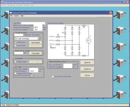
41 Problem solved using SAF/PE Fig.30 shows a typical datasheet for a 3-phase GTO inverter. It is desired to protect the inverter with a single fuse in the F2 location. The fuse is to be selected from the square-bodied PSC range size 3x. Fig.30 Input to datasheet in SAF/PE 41

42 Select-A-Fuse for Power Electronics (SAF/PE) Clicking on Search gives the window shown in Fig.31. Fig.31 After clicking Search on the datasheet The square-bodied PSC fuses in sizes 30, 31, 32, and 33 have been selected, and the location set as F2. Clicking Search then gives the screen shown in Fig

43 Problem solved using SAF/PE Fig.32 Results of search The search results show no suitable fuse can be found in size 30 (the smallest physical size). However a 700A fuse in the next larger size 31 would be suitable, and this would normally be the recommended fuse, for reasons of size and cost. (The suffixes b and s indicate that this fuse is available with both blade and stud type end contacts). Double clicking on the PSC-31-URD line (or using the Analyse button on the main datasheet) then ives a detailed report. This shows to what extent the 700A fuse meets the requirements of the application, as shown in Fig

44 Select-A-Fuse for Power Electronics (SAF/PE) Fig. 33 Detailed analysis for the selected fuse This section gave a brief illustration of the one of the circuits included in SAF/PE. For further information about SAF/PE contact Ferraz Shawmut Technical Services. 44
45 Appendix (a) summary of coefficients used in fuse selection To allow for : Coefficient Notes ambient temperature A1 where a = ambient. a o a = ºC. o = ºC. A1 = a - o (See section 5). forced cooling Bv Increases linearly from 1.0 to B1 at v = 5m/s then constant. Typically B1 = (See section 5). cable/bus size C1 To allow for the fact that in service the cooling effect of the connections (cables, busbars) will normally be less favorable than was used in the type tests used for establishing the current rating. (See section 5 and Appendix b). proximity & skin effect CPE To allow for proximity and skin effects at high frequencies. (See section 5). fluctuations in load current A 2 To allow for variations in r.m.s. current - see section 2. Consult Ferraz Shawmut for cyclic loads. (See section 5). repetitive cyclic overloads B 2 Ratio of the maximum repetitive overload current to the melting current, to ensure that the fuse will endure a given number of cycles. (See section 6). occasional overload Cf3 Ratio of the maximum occasional overload current, in relation to the melting current, to ensure that the fuse will survive without adverse effects. (See section 7). 45
46 Appendix (b) typical values of C1 for Ferraz Shawmut fuses FUSE TECHNOLOGY (construction) TYPE C1 without liquid cooling on terminals C1 with liquid cooling to keep the fuse contacts below 60 C on both sides & doubles UR gr & doubles UR gr & doubles UR square gr & doubles UR gr UR & doubles gr- 1 1 longer bodies all V to 300 V round 500 V to fibre-glass 1100 to 1500 V V to 3000 V above 3000 V 1 1 A13X(amp)-1 or 2 A13Z(amp)-1 or 2 0,80 1,30 A25X (amp)-1 or 2 A25Z(amp)-1 or 2 A50P(amp)-1,1DS A70P(amp)-1,1DS A60X(amp)-1 0,85 1,20 A60Z(amp)-1 A100P(amp)-1,1A A100X(amp)-1,1A A100Z(amp)-1,1A American A70QS(rating)-14F 0,90 1 ferrules 14FI, 22F, 22FI A60Q(rating)-2 0,90 1 A120X(rating)-2 A150P(rating)-1 A150X(rating)-1 or 1W 0,90 1,1 A150Z(rating)-1 or 1W European all sizes according to the rated power of the ferrules SIZE fuse-holder : see the de-rating table of the holder published in the ADVISOR 46
47 Appendix (c) other principal symbols used in this guide General r.m.s. root-mean-square In nominal continuous current rating A In continuous current rating in a real-world application A I instantaneous curren A I 2 t integral of i over a specified period of time A 2 s temperature ºC o reference ambient temperature ºC a ambient temperature in a real-world application ºC F instantaneous voltage across fuse V K I 2 t correction factor (for applied voltage) VPK peak arc voltage of fuse V KM Meyer s constant A 2 s mm- 4 A cross-sectional area mm 2 A.C. circuit V r.m.s. source voltage V I r.m.s. prospective (available) short-circuit current A f frequency Hz angular frequency ( = 2 f ) rad/s L inductance H R resistance angular instant at which short-circuit occurs w.r.t. voltage rad wave circuit power-factor angle (= tan -1 vv L/R ) rad X circuit inductive reactance (= vv L ) D.C. circuit VDC source voltage V T circuit time constant (= L/R ) s IRMS effective r.m.s. current for a specified time A cyclic loading IMELT r.m.s. current which will cause melting in a specified time A IRMS r.m.s. current over a complete cycle A pu RMS per-unit r.m.s. loading ( = IRMS /In ) KN, x, y parameters in cyclic endurance equation N number of cycles highest peak-to-peak temperature excursion within fuse C 47
48 Semiconductor device Appendix IFSM peak half-cycle surge withstand current of semiconductor A device I0 r.m.s. surge withstand current (= IFSM / 2 ) A t0 duration of half-cycle s N exponent in device withstand formula I N t = constant Line-commutated converters F1 denotes fuse in series with device to be protected F2 denotes fuse in line input to converter (F1 or F2 fuses are used, but not both) F3 denotes fuse on d.c. side Ed0 maximum d.c. output of line-commutated converter V A, B, C instantaneous a.c. source voltages V n number of parallel paths (legs) in high-power converter ILEG r.m.s. current per leg A IF r.m.s. fault current A P prearcing (melting) I 2 t A 2 s T total clearing I 2 t A 2 s KAC a.c. voltage rating factor for regenerative converter KDC d.c. voltage rating factor for regenerative converter Forced-commutated inverters R2,L2 leg resistance & inductance, H RF, LF supply filter resistance & inductance, H C reservoir capacitance F EM maximum permissible capacitor voltage V UPM maximum permissible capacitor voltage at start of arcing V 48
49 Ferraz Shawmut Technical Services - contact information Europe - Asia - Pacific - Africa - Middle East - South America Ferraz Shawmut 1, rue Jean Novel F VILLEURBANNE FRANCE Fax: +33 (0) Senior Fusing Expert Charles Mulertt Phone: +33 (0) Fax: +33 (0) charles.mulertt@fr.ferrazshawmut.com Applications Engineers: Jean Claude Chenu Phone: +33 (0) Fax: +33 (0) jean.claude.chenu@fr.ferrazshawmut.com Franck Charlier Phone: +33 (0) Fax: +33 (0) franck.charlier@fr.ferrazshawmut.com Denis Pellisson Phone: +33 (0) Fax: +33 (0) denis.pellison@fr.ferrazshawmut.com North & Central America 374 Merrimac Street Newburyport, MA USA Fax: Toll Free Fax: Director, American Technical Services Kent Walker Phone: kent.walker@ferrazshawmut.com Applications Engineers: Cindy Cline Phone: cindy.cline@ferrazshawmut.com Kimberley Walters Phone: kimberley.walters@ferrazshawmut.com Dawn Radziewicz Phone: dawn.radziewicz@ferrazshawmut.com Ferraz Shawmut Canada Lew Silecky 88 Horner Avenue Toronto, ON M8Z 5Y3 CANADA Phone: Toll Free Fax: Lew.Silecky@ferrazshawmut.com 49
50 50
51

52 Global Headquarters / Ferraz Shawmut 1, rue Jean Novel F Villeurbanne France Phone : +33 (0) Fax : +33 (0) North American Headquarters / Ferraz Shawmut 374 Merrimac Street Newburyport, MA Phone : Fax : Amalgame - SC003-10/2006
Ultra-Rapid Fuse Links for the Protection of Semiconductor Rectifiers
 Ultra-Rapid Fuse Links for the Protection of Semiconductor Rectifiers 1.General The design of rectifier equipment requires specific provisions in the switchgear for the protection of power semiconductor
Reducing. with Current. arc flash note 2. points of interest. Why Use Current Limiting Fuses. By mike lang, Principal field engineer
 Reducing Arc Energies with Current Limiting Fuses arc flash note 2 By mike lang, Principal field engineer Why Use Current Limiting Fuses Current limiting fuses can reduce both the magnitude and duration
FUSES FOR SEMICONDUCTORS
 FUSES FOR SEMICONDUCTORS. POWER SEMICONDUCTORS.. Three families of power semiconductors.. Power semiconductors history.3. Current conversion: one application of the power semiconductors.4. Power semiconductors
FUSE TECHNOLOGY Ambient temperature
 This fuse technology guide will discuss basic fuse operating, application, and selection criteria concepts. The intended purpose of this section is to aid designers with the operation and characteristics
3.2. Current Limiting Fuses. Contents
 .2 Contents Description Current Limiting Applications................. Voltage Rating.......................... Interrupting Rating....................... Continuous Current Rating................ Fuse
Leadership in fusible circuit protection
 Bussmann series High speed fuse application guide Leadership in fusible circuit protection SERIES Eaton is the leading source of fusible circuit protection solutions in the global marketplace. Eaton s
POWR-SPEED FUSES TECHNICAL APPLICATIONS GUIDE
 POWR-SPEED FUSES TECHNICAL APPLICATIONS GUIDE TABLE OF CONTENTS 1.0 INTRODUCTION... 3 2.0 POWER SEMICONDUCTOR DEVICES... 4 2.1 Power Semiconductor Device Classification... 4 3.0 OVERCURRENT PROTECTION
Application Guide Effective June Protecting semiconductors with high speed fuses
 pplication Guide 10507 Effective June 2016 Protecting semiconductors with high speed fuses Contents : Introduction 3 bout this guide 3 Background 3 Typical fuse construction 3 Fuse operation 4 Power semiconductors
Fuseology. High Speed Fuses
 Fuseology High Speed Fuses The protection needs for solid-state power equipment often differ from electrical equipment; hence, the high speed fuse evolved. The protection of power diodes and SCRs requires
Miniature circuit breaker Application guide
 Miniature circuit breaker Application guide Miniature Miniature circuit circuit breakers breakers Application S200 guide Introduction The circuit breaker plays an important role in providing over-current
Ultra Rapid Fuses. For Semiconductor Protection
 UR Ultra Rapid Fuses For Semiconductor Protection Over many decades SIBA has developed a very comprehensive product line of Ultra Rapid fuses that has achieved worldwide acceptance. SIBA's worldwide distribution
FUSE: SAFE & RELIABLE
 FUSE: SAFE & RELIABLE VS. CIRCUIT BREAKER Tech Topics: Selective Coordination Note 2, Issue 1 Franck Charlier Technical Support Engineer Points of interest: Power fuse needs no repair only to be replaced
Fuses still the best form of overload protection
 Fuses still the best form of overload protection 2001 George Moraitis (Fuseco Pty. Ltd.) Often when I visit people to talk about circuit protection I hear the comments fuses are a thing of the past and
Characteristics of LV circuit breakers Releases, tripping curves, and limitation
 Characteristics of LV circuit breakers Releases, tripping curves, and limitation Make, Withstand & Break Currents A circuit breaker is both a circuit-breaking device that can make, withstand and break
Lecture 2. Power semiconductor devices (Power switches)
") Lecture 2. Power semiconductor devices (Power switches) Power semiconductor switches are the work-horses of power electronics (PE). There are several power semiconductors devices currently involved in
Lecture 2. Power semiconductor devices (Power switches) Power semiconductor switches are the work-horses of power electronics (PE). There are several power semiconductors devices currently involved in
MAHALAKSHMI ENGINEERING COLLEGE TIRUCHIRAPALLI
 MAHALAKSHMI ENGINEERING COLLEGE TIRUCHIRAPALLI 621213 QUESTION BANK --------------------------------------------------------------------------------------------------------------- Sub. Code : EE2402 Semester
ECET Distribution System Protection. Overcurrent Protection
 ECET 4520 Industrial Distribution Systems, Illumination, and the NEC Distribution System Protection Overcurrent Protection One of the most important aspects of distribution system design is system protection.
Power systems Protection course
 Al-Balqa Applied University Power systems Protection course Department of Electrical Energy Engineering Dr.Audih 1 Part 3 Protective Devices Fuses & Circuit Breakers 2 Introduction: Fuse Is advice used
TERMS AND DEFINITIONS
 Application Guide Adjustable Alarm Level A setting on a protection relay at which an LED or an output contact operates to activate a visual or audible alarm. Adjustable Delay A setting on a protection
Fuses Introductory Information
 Fuses Introductory Information Why a Fuse? There are many possible cases for overcurrents to occur due to a malfunction in appliances, including short-circuits: In low output power applications, miniature
onlinecomponents.com
 66 grb 66 V AC grb - from up to 3 A Size: x38 The fuse preselection table below indicates: Fuse preselection Rated current Pre-arcing I²t Total I²t at 66VAC I N (A) I²t p (A²s) I²t (A²s) - rated current
Semiconductor Fuses European Fuses
 66 grb 66 V AC grb - from up to 3 A Size: x38 The fuse preselection table below indicates: Fuse preselection - rated current (or ) I N - pre-arcing I²t (I²t p ) at ms - total ope I²t (I²tt) at 66 V, cos
FUSES. Safety through quality
 Safety through quality HH HIGH VOLTAGE Over many decades SIBA has developed a global product line of High Voltage Fuses that are comprehensive for any and all applications. Superior engineering, advanced
Medium-voltage fuses 3 kv 40.5 kv, 0.4 A 315 A
 DISTRIBUTION SOLUTIONS Medium-voltage fuses 3 kv 40.5 kv, 0.4 A 315 A Continuous protection and reliable operation Proven design and compliance with newest fuses standards Compatibility with other ABB
Semiconductor (AC) fuses
 fuses") Main characteristics 450 TO 700VAC / 63 TO 2800A Recognized Exceptionally low I 2 T, Watt losses. Non-magnetic construction, Highly reliable low voltage Trip-indicator system, conformity to UL, IEC, DIN
Main characteristics 450 TO 700VAC / 63 TO 2800A Recognized Exceptionally low I 2 T, Watt losses. Non-magnetic construction, Highly reliable low voltage Trip-indicator system, conformity to UL, IEC, DIN
Secondaries. arc flash note Introduction. By Mike Lang, engineer and. Services Supervisor
 Reducing Arc Flash Energies on Transformer Secondaries arc flash note 6 By Mike Lang, principal field engineer and Dave Komm, Technical Services Supervisor 1. Introduction Arc flash incident energy calculations
SLOVAK UNIVERSITY OF TECHNOLOGY Faculty of Material Science and Technology in Trnava ELECTRICAL ENGINEERING AND ELECTRONICS.
 SLOVAK UNIVERSITY OF TECHNOLOGY Faculty of Material Science and Technology in Trnava ELECTRICAL ENGINEERING AND ELECTRONICS Róbert Riedlmajer TRNAVA 2007 Unit 14 - Fundamentals of power system protection
EE 741 Over-voltage and Overcurrent. Spring 2014
 EE 741 Over-voltage and Overcurrent Protection Spring 2014 Causes of Over-voltages Lightning Capacitor switching Faults (where interruption occurs prior to zero current crossing) Accidental contact with
Application Note CTAN #127
 Application Note CTAN #127 Guidelines and Considerations for Common Bus Connection of AC Drives An important advantage of AC drives with a fixed DC is the ability to connect the es together so that energy
High Speed Fuse Applications Module 5
 High Speed Fuse Applications Module 5 Power Semiconductors GTO SSR Semiconductors: High speed electronic switches used to manipulate electrical power Diode Thyristor IGBT Module 5 - page 2 2 Application
Evaluating Selective Coordination Between Current-Limiting Fuses And Non Current-Limiting Circuit Breakers
 Evaluating Selective Coordination Between And Non Current-Limiting Circuit Breakers Tech Topics: Selective Coordination Note 1, Issue 1 Steve Hansen Sr. Field Engineer Robert Lyons Jr. Product Manager
MOLDED CASE CIRCUIT BREAKER BASICS. David Castor, P.E.
 MOLDED CASE CIRCUIT BREAKER BASICS David Castor, P.E. History of MCCBs 1904 - Cutter Manufacturing Co., Philadelphia, produces circuit breakers. They called it the Inverse Time Element breaker, or I-T-E
Medium voltage products. Fuses
 Medium voltage products Fuses Index Introduction... 3 Main definitions... 4 ABB HV Fuses with Temperature Control Unit... 5 General principles for fuse link selection... 6 CEF... 8 CEF-S... 16 CEF-VT...
Evaluating Selective Coordination Between
 Evaluating Selective Coordination Between Current-Limiting Fuses And Non Current- Limiting Circuit Breakers selective coordination note 1 By Steve Hansen Sr. Field Engineer and Robert Lyons Jr. Product
Technical Guide No. 7. Dimensioning of a Drive system
 Technical Guide No. 7 Dimensioning of a Drive system 2 Technical Guide No.7 - Dimensioning of a Drive system Contents 1. Introduction... 5 2. Drive system... 6 3. General description of a dimensioning
RECOMMENDATIONS FOR USING FREQUENCY INVERTERS WITH POSITIVE DISPLACEMENT REFRIGERANT COMPRESSORS
 RECOMMENDATIONS FOR USING FREQUENCY INVERTERS WITH POSITIVE DISPLACEMENT REFRIGERANT COMPRESSORS Contents Page 1 Scope and purpose... 1 2 General... 1 3 Operation... 2 4 Application ranges... 5 5 Design
Selective Coordination
 Circuit Breaker Curves The following curve illustrates a typical thermal magnetic molded case circuit breaker curve with an overload region and an instantaneous trip region (two instantaneous trip settings
THIN FILM FUSE LINK. R D Harrison*, I Harrisont, A F Howet.
 169 THIN FILM FUSE LINK R D Harrison*, I Harrisont, A F Howet. *Bussman Division Cooper (UK) Ltd, Burton on the wolds, Leicestershire, LEI 2 5TH, UK. tdepartment of Electrical and Electronic Engineering,University
LESSON Transmission of Power Introduction
 LESSON 3 3.0 Transmission of Power 3.0.1 Introduction Earlier in our previous course units in Agricultural and Biosystems Engineering, we introduced ourselves to the concept of support and process systems
CHAPTER 3 CAUSES AND EFFECTS OF ELECTRICAL FAULTS
 22 CHAPTER 3 CAUSES AND EFFECTS OF ELECTRICAL FAULTS 3.1 INTRODUCTION A large number of asynchronous motors are used in industrial processes even in sensitive applications. Consequently, a defect can induce
DX 3 MCBs. Choice of DX 3 MCBs for capacitor banks. Technical data
 Specifications IS/IEC 60898-1 2002 Number of poles SP, SPN, DP, TP, TPN, FP Characteristics C & D Curve Breaking capacity 10 ka 0.5 A to 63 A as per IS/IEC 60898-1 2002 16 ka for 0.5 A to 25 A as per IEC
NX indoor current-limiting fuses
 Fusing Equipment Catalog Data CA132049EN Supersedes 240-60 September 2009 COOPER POWER SERIES NX indoor current-limiting fuses General Eaton provides overload protection for all indoor and underground
OUTPUT SHORT-CIRCUIT CURRENT BEARABLE BY THE UPS
 OUTPUT SHORT-CIRCUIT CURRENT BEARABLE BY THE UPS Abstract According to the standards, an overcurrent is a current which exceeds its rated value. Overcurrents can arise in different modalities, depending
Utilization of Electric Power Laboratory 3 rd Year G2: Testing & Characteristic of MCCB Used in Commercial and Industrial Applications
 G2: Testing & Characteristic of MCCB Used in Commercial and Industrial Applications Contents 1. Laboratory Objective... 4 2. MECHANICAL OPERATION TESTS... 4 2.1 Purpose... 4 2.2 Procedure... 4 2.3 Results...
Learning Objectives:
 Topic 5.5 High Power Switching Systems Learning Objectives: At the end of this topic you will be able to; recall the conditions under which a thyristor conducts; explain the significance of the following
Surge Current, I 2 t Value and Short - Circuit Protection of High Power Semiconductors.
 Date: 30.05.2005 Page 1 Surge Current, I 2 t Value and Short - Circuit Protection of High Power Semiconductors. According to DIN IEC 60747 the maximum rated surge current is the maximum allowable non periodical,
Application Notes. Calculating Mechanical Power Requirements. P rot = T x W
 Application Notes Motor Calculations Calculating Mechanical Power Requirements Torque - Speed Curves Numerical Calculation Sample Calculation Thermal Calculations Motor Data Sheet Analysis Search Site
MEDIUM VOLTAGE PRODUCTS. Fault Current Limiters I S. -limiter and FC-Protector The worldʼs fastest switching devices
 MEDIUM VOLTAGE PRODUCTS The worldʼs fastest switching devices 2 FAULT CURRENT LIMITERS THE WORLDʼ S FASTETST SWITCHING DEVICES The worldʼs fastest switching devices ABBʼs fault current limiters disconnect
ELECTRICAL POWER and POWER ELECTRONICS
 Introduction to ELECTRICAL POWER and POWER ELECTRONICS MUKUND R PATEL (cj* CRC Press Taylor & Francis Group Boca Raton London New York CRC Press is an imprint of the Taylor & Francis Croup, an informa
2.1 Warnings & Agency Approvals Electrical Connections - Specifications Standard Wiring Configurations...2 4
 CHAPTER ELECTRICAL 2 INSTALLATION Contents of this Chapter... 2.1 Warnings & Agency Approvals..................2 2 2.1.1 Isolation..............................................2 2 2.1.2 Electrical Power
CI-TI Contactors - VLT Frequency Converters
 MN.90.K1.02 - VLT is a registered Danfoss trademark 1 Description This data sheet is based on tests made in co-operation with Contactor Business from Danfoss Automatic Division and Danfoss Drives A/S.
2.0 CONSTRUCTION 3.0 OPERATION. SA-1 Generator Differential Relay - Class 1E 2.5 TRIP CIRCUIT
 41-348.11C SA-1 Generator Differential Relay - Class 1E 2.0 CONSTRUCTION The type SA-1 relay consists of: Restraint Circuit Sensing Circuit Trip Circuit Surge Protection Circuit Operating Circuit Amplifier
NH Solid Blades 690 VAC sizes 000 to 3
 NH Solid Blades 6 VAC sizes 000 to gs-class Protistor NH 6 VAC fuse-links provide maximum flexibility in equipment design and ultimate protection for today s power conversion equipment. This range is a
Fuse Link Designation
 Westinghouse The fundamental use of distribution fuse links is in fuse cutouts to provide protection for electrical equipment against faults and overloads, and increased system service continuity through
CHAPTER 3 TRANSIENT STABILITY ENHANCEMENT IN A REAL TIME SYSTEM USING STATCOM
 61 CHAPTER 3 TRANSIENT STABILITY ENHANCEMENT IN A REAL TIME SYSTEM USING STATCOM 3.1 INTRODUCTION The modeling of the real time system with STATCOM using MiPower simulation software is presented in this
Protection of Power Electronic Multi Converter Systems in AC and DC Applications
 Protection of Power Electronic Multi Converter Systems in AC and DC Applications Prof. Norbert Grass Technische Hochschule Nürnberg, Institute for Power Electronic Systems, Nuremberg, Germany, Norbert.Grass@th-nuernberg.de
The University of New South Wales. School of Electrical Engineering and Telecommunications. Industrial and Commercial Power Systems Topic 2
 The University of New South Wales School of Electrical Engineering and Telecommunications Industrial and Commercial Power Systems Topic 2 SWITCHBOARDS Overview Also called Switchgear and Controlgear Assembly
CHAPTER 6 MECHANICAL SHOCK TESTS ON DIP-PCB ASSEMBLY
 135 CHAPTER 6 MECHANICAL SHOCK TESTS ON DIP-PCB ASSEMBLY 6.1 INTRODUCTION Shock is often defined as a rapid transfer of energy to a mechanical system, which results in a significant increase in the stress,
Installation Manual for DC Injection Brake Units
 Power Drive Services INJ Series DC brake modules PDS 11-30-100A Page 1 of 17 Issue 15 Contents. 1. Safety. 2. Installation. 3. Setting Up. 4. Wiring Diagrams. 5. Specifications. 6. Selection. 7. Timing
Application Note CTAN# 223
 Application Note CTAN# 223 The Application Note is pertinent to the entor II / Quantum III Family Inversion Faults in Regenerative DC Drives This application note will try to describe what an inversion
THE PROTECTION OF INDUSTRIAL CAPACITOR BANKS BY CURRENT LIMITING FUSES. By M.J. Smart and B. Wadcock
 203 THE PROTECTION OF INDUSTRIAL CAPACITOR BANKS BY CURRENT LIMITING FUSES By M.J. Smart and B. Wadcock 1.0 INTRODUCTION Capacitors are widely used for industrial power factor correction throughout the
Single Pole Circuit Protectors 55. Multi-Pole Circuit Protectors 56. Configurations 58. Operating Characteristics 59.
 Single Pole Circuit Protectors 55 Multi-Pole Circuit Protectors 56 Configurations 58 Operating Characteristics 59 Delay Curves 60 Specifications 61 Decision Tables 62 SINGLE POLE CIRCUIT PROTECTORS The
Controls HIGH SPEED FUSES
 Controls HIGH SPEED FUSES 0800 367 934 High Speed Fuses HIGH SPEED FUSES Summary High Speed Fuses 4 Time vs. Current Curves 7 Current limitation curves 11 High Speed Fuses 15 Accessories 17 Dimensions
Advanced Design - Legendary Performance - Superior Circuit Protection - Count on it. An Introduction to Overcurrent Protection
 Overview - Whitepaper Articles 1.1 1.4 An Introduction to Overcurrent Protection Potentially damaging overcurrents occur in electrical circuits due to either sustained overloads or inadvertent transient
RESIDUAL CURRENT CIRCUIT BREAKER
 Quality Features Mid Trip - Different knob position to indicate whether the device is Switched OFF by a fault or Switched OFF manually Inscription Window - Ensures circuit identification and hence reduces
Exercise 6. Three-Phase AC Power Control EXERCISE OBJECTIVE DISCUSSION OUTLINE DISCUSSION. Introduction to three-phase ac power control
 Exercise 6 Three-Phase AC Power Control EXERCISE OBJECTIVE When you have completed this exercise, you will know how to perform ac power control in three-phase ac circuits, using thyristors. You will know
Protective firing in LCC HVDC: Purposes and present principles. Settings and behaviour. V. F. LESCALE* P. KARLSSON
 21, rue d Artois, F-75008 PARIS B4-70 CIGRE 2016 http : //www.cigre.org Protective firing in LCC HVDC: Purposes and present principles. Settings and behaviour. V. F. LESCALE* P. KARLSSON VILES Consulting
3NP1 Fuse Switch Disconnectors up to 630 A
 Switch Disconnectors 3NP1 Fuse Switch Disconnectors up to 630 A Introduction Overview All key product features at a glance available for all sizes Connection of circular conductors and laminated conductors
3 - Protection components Motor circuit-breakers
 Contents 0 - Protection components Motor circuit-breakers protection components for the motor protection Thermal-magnetic motor circuit-breakers Selection guide..............................................page
Fast thyristors. When burning for induction heating solutions.
 Fast thyristors. When burning for induction heating solutions. By Ladislav Radvan, ABB s.r.o., Semiconductors. Published by Power Electronics Europe (August 2014) Induction heating is one of the key metal
Using Fuses to Provide Fault Protection of Windfarm Transformers
 Using Fuses to Provide Fault Protection of Windfarm Transformers Dan Gardner R&D Manager, Hi-Tech Fuses, Thomas & Betts John G. Leach Consultant, Hi-Tech Fuses Abstract A rising concern among utilities
DYNACOMP. The top-class reactive power compensator
 DYNACOMP The top-class reactive power compensator Dynacomp vs Electromechanical switching of capacitors Electromechanical switching of capacitors The Dynacomp : the top-class dynamic compensator Transients
Thermal system protection of switchgear through high voltage fuse links with integrated temperature limiter under consideration of IEC 420:1990
 66 Thermal system protection of switchgear through high voltage fuse links with integrated temperature limiter under consideration of IEC 420:1990 Dipl.-Ing. U. Haas SIBA, Sicherungen-Bau GmbH, Lünen,
School of Electrical and Information Engineering. ELEC High Voltage. University of Sydney. Dr Keith Mitchell. Engineering
 University of Sydney School of Electrical and Information Engineering Dr Keith Mitchell ELEC 5205 - High Voltage Engineering ELEC 5205 - High Voltage Engineering 3. Switchgear Types of Power System Switchgear
Synchronous Generators I. EE 340 Spring 2011
 Synchronous Generators I EE 340 Spring 2011 Construction of synchronous machines In a synchronous generator, a DC current is applied to the rotor winding producing a rotor magnetic field. The rotor is
Application Information Need to know how? You ve turned to the right place...literally.
 Need to know how? You ve turned to the right place...literally. Your problem: Whether your objective is optimum protection of motor control equipment, power or control transformers, cable wiring, or lighting
Synchronous Generators I. Spring 2013
 Synchronous Generators I Spring 2013 Construction of synchronous machines In a synchronous generator, a DC current is applied to the rotor winding producing a rotor magnetic field. The rotor is then turned
Low Voltage Fuses General information
 General information Description FUJI low voltage current-limiting fuses are designed to give protection to power supply and distribution circuits and equipment such as motor starter and semiconductors.
Medium voltage products. Fuses
 Medium voltage products Fuses Index Introduction... 3 Main definitions... 4 ABB HV Fuses with Temperature Control Unit... 5 General principles for fuse link selection... 6 CEF... 8 CEF-S... 16 CEF-VT...
EUROPEAN HIGH VOLTAGE FUSES
 EUROPEAN HIGH VOLTAGE FUSES AS PER IEC 60282 EDUPACK TRAINING MODULE 2012 HH DIN NF MEDIUM OR HIGH VOLTAGE FUSE? High Voltage is the official definition provided by the standard. High Voltage starts just
Fig 1. Circuit Breakers
 Protective Devices for Electrical Control Equipment Fuses, Circuit breakers, Chop off Circuits, Crowbars, Thermostats Arthur Holland, Holland Technical Skills In previous columns I have dealt with protection
Switch Disconnectors. SENTRON 3NP5 Fuse Switch Disconnectors up to 630 A. Introduction. 7/106 Siemens LV
 Switch Disconnectors Introduction Siemens AG 2010 Overview 3NP5 0 3NP5 2 3NP5 fuse disconnector range 3NP5 4 SENTRON 3NP5 fuse disconnectors are controls for the occasional manual ing/isolating of loads
SDC,Inc. SCR-Regenerative Ac Drive
 SDC,Inc WWW.STEVENSDRIVES.COM APPLICATION NOTE #: AN_REG_GEN000 EFFECTIVE DATE: 12 MAR 02 SUPERSEDES DATE: Original NO. OF PAGES: 10 SCR-Regenerative Ac Drive Using a regeneration controller with adjustable-frequency
6/4/2017. Advances in technology to address safety. Thomas A. Domitrovich, P.E., LEED AP VP, Technical Sales Eaton
 Advances in technology to address safety Thomas A. Domitrovich, P.E., LEED AP VP, Technical Sales Eaton 1 Advances in technology could mean use existing technology & back to basics Advances in safety are
3. OPERATION 2.1. RESTRAINT CIRCUIT 2.6. INDICATING CIRCUIT 2.2. OPERATING CIRCUIT 2.7. SURGE PROTECTION CIRCUIT 2.3.
 41-348.1H Type SA-1 2.1. RESTRAINT CIRCUIT The restraint circuit of each phase consists of a center-tapped transformer, a resistor, and a full wave rectifier bridge. The outputs of all the rectifiers are
DIN HV Distribution. DIN HV fuses are partial-range high voltage currentlimiting fuses for use in distribution circuits from kV.
 DIN HV Distribution DIN HV fuses are partial-range high voltage currentlimiting fuses for use in distribution circuits from 2.3-38kV. Their compact dimensions and non-venting characteristics make them
Design Standards NEMA
 Design Standards Although several organizations are involved in establishing standards for the design, construction, and application of motor control centers, the primary standards are established by UL,
Fuseology. Dual-Element, Time-Delay Fuse Operation
 Dual-Element, Time-Delay Fuse Operation There are many advantages to using these fuses. Unlike single-element fuses, the Cooper Bussmann dual-element, time-delay fuses can be sized closer to provide both
Bulletin 1489 Circuit Breakers. Selection Guide
 Bulletin 1489 s Selection Guide Bulletin 1489-A Overview/Description Bulletin 1489-A s Energy-limiting design protects downstream components better than conventional breakers during short circuits Field-mountable
Effective discrimination of protective devices
 Effective discrimination of protective devices In the event of a fault occurring on an electrical installation only the protective device nearest to the fault should operate,leaving other healthy circuits
SECTION 3 HPS CENTURION R REACTORS AND RC DV/DT FILTERS
 HPS CENTURION R REACTORS AND RC DV/DT FILTERS Single and Three Phase Why Choose a Line Reactor?... 98 Construction Features... 100 HPS Centurion R Reactors Specifications... 101 Part Number Guide... 102
High Speed Fuses. Section Contents Page
 Section Contents Page General pplications.......................1-13 North merican fuses & accessories...........1-11 DFJ - High speed Class J fuse.................. 15 Square ody fuses & accessories............
The University of New South Wales. School of Electrical Engineering and Telecommunications. Industrial and Commercial Power Systems Topic 6
 The University of New South Wales School of Electrical Engineering and Telecommunications Industrial and Commercial Power Systems Topic 6 PROTECTIONS 1 FUNCTION OF ELECTRICAL PROTECTION SYSTEMS Problems:
RBA Catalog Numbers and Information
 50 RBA s and Information Type RBA Expulsion Fuses for Use Indoors or in an Enclosure Ampere Rating Standard Speed (Fuse Refills) Curve Reference 36-635 Time-Lag (Fuse Refills) Curve Reference 36-635 Approx.
XP600/1100/2000 INSTALLATION AND OPERATION MANUAL
 7317 Jack Newell Blvd North Fort Worth, Texas 76118-71 817-595-4969 voice, 817-595-129 fax 8-886-4683 toll free website wwwexeltechcom Manufacturer of UL Listed Products Copyright 21 Exeltech Inc All rights
Design and Reliability of a High Voltage, high Current Solid State Switch for Magnetic Forming Applications
 Design and Reliability of a High Voltage, high Current Solid State Switch for Magnetic Forming Applications A. WELLEMAN, R. LEUTWYLER, S. GEKENIDIS ABB Switzerland Ltd, Semiconductors, Fabrikstrasse 3,
AP/UP, AP/MIL Series Magnetic Circuit Protectors
 AP/UP, AP/MIL AP/UP, AP/MIL Series Magnetic Circuit Protectors Introduction 68 Single Pole 69 Multi-Pole 70 Configurations 72 Operating Characteristics 73 Delay Curves 74 Specifications 75 Decision Tables
Thyristors Characteristics
 Electrical Engineering Division Page 1 of 15 A thyristor is the most important type of power semiconductor devices. They are extensively used in power electronic circuits. They are operated as bi-stable
M T E C o r p o r a t i o n MATRIX FILTER. SERIES B Volts, 50HZ USER MANUAL PART NO. INSTR REL MTE Corporation
 M T E C o r p o r a t i o n MATRIX FILTER SERIES B 380-415 Volts, 50HZ USER MANUAL PART NO. INSTR - 015 REL. 060628 2006 MTE Corporation IMPORTANT USER INFORMATION NOTICE The MTE Corporation Matrix Filter
Principles of Electrical Engineering
 D.C GENERATORS Principle of operation of D.C machines, types of D.C Generators, e.m.f equation of D.C Generator, O.C.C of a D.C Shunt Generator, Load characteristics of D.C.Generators GENERATOR PRINCIPLE: