AMVAC TM and ADVAC TM Breaker commissioning procedures
|
|
|
- Juniper Brown
- 6 years ago
- Views:
Transcription


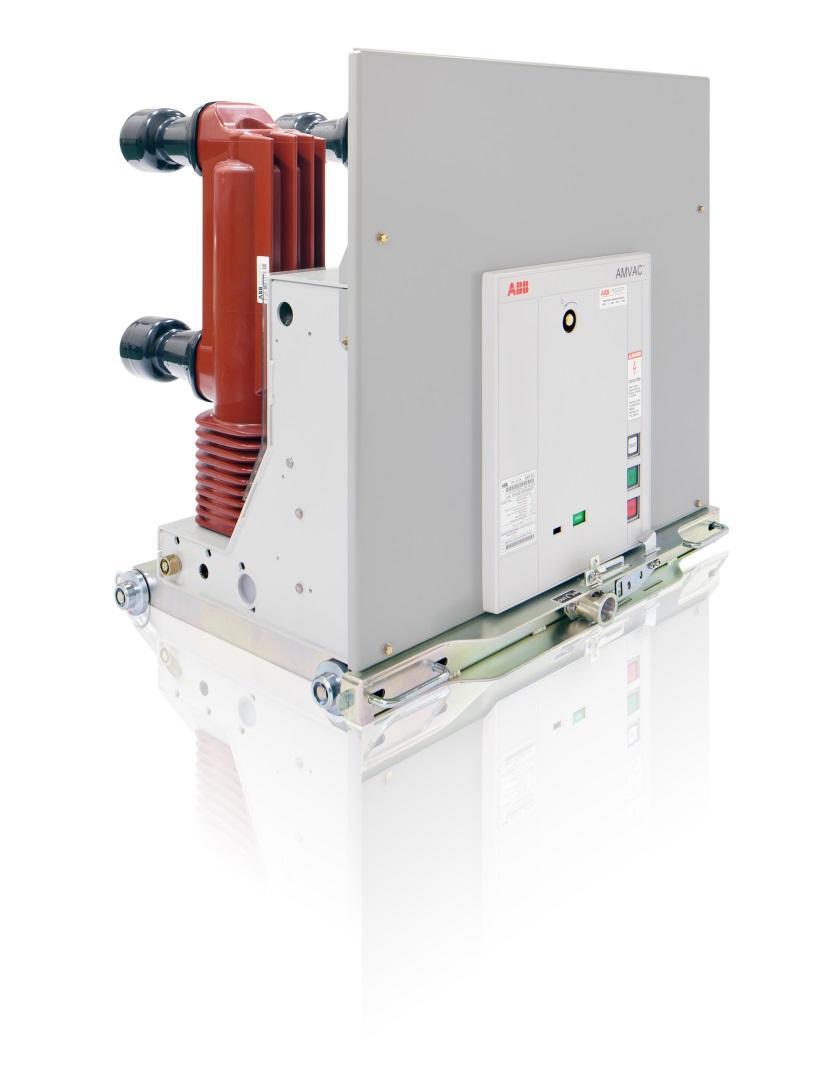
1 AMVAC TM and ADVAC TM Breaker commissioning procedures
2 1VAL0501-MB Rev A, Oct. 2015
3 Table of Contents 1 Important Safety Notes & Warnings Safety Notations Introduction General Instructions Scope of Instructions Inspection, Handling and Storage Inspection Handling Storage Procedures Receiving inspection Truck mounting Functional Test Primary Circuit Test Cell Insertion Racking, DISCONNECT to TEST In Cell Testing Racking, TEST to CONNECT Racking, CONNECT to TEST Racking, TEST to DISCONNECT` Removal Standard Color Galvanized Steel Frame Construction Primary Disconnect Assemblies Secondary Disconnecting Devices Ground Bus Contacts Month (Two Year) Inspection Renewal Parts End of life of Product Methods of Disposal Disclaimer of Warranties and Limitation of Liability ADVAC AMVAC Commissioning Checklist 1of VAL0501-MB Rev A, Oct. 2015
4 1 Important Safety Notes & Warnings Equipment operation depends on proper handling, installation, and maintenance. Neglecting fundamental requirements may lead to injury of personnel, failure of the equipment and property damage. Safety as described in this instruction book involves two conditions: Personal injury. Product or property damage. 1.1 Safety Notations Safety notations alert personnel to possible death, injury or property damage situations. The safety notations appear before the step in which the condition applies. The one safety notice and three hazard levels notations are: WARNING Warning indicates a hazardous situation that has some probability of severe injury and substantial property damage. DANGER Danger indicates a hazardous situation that has a high probability of death, severe injury, and substantial property damage. Personnel installing, operating, or maintaining this equipment must have thorough knowledge of all applicable local, regional, industry, government, and OSHA safety procedures as well as commonly accepted safe working practices. Personnel working in or around this equipment must also exhibit common sense and good judgment regarding the potential hazards for themselves and other personnel in the area. These instructions are intended for use by fully qualified personnel and are not a substitute for adequate training, experience and supervision. Should clarification or additional information be required, refer the matter to your nearest ABB Sales office. 2 Introduction NOTICE indicates a statement of company policy as it relates to the safety of personnel or protection of property 2.1 General Instructions Read these instructions carefully before installation and use as a guide during installation and initial operation. Use of these instructions will facilitate proper receiving of the equipment and prolong its useful life. CAUTION Caution indicates a hazardous situation that may result in minor or moderate injury and/or property damage. Page 1

5 2.2 Scope of Instructions The instructions are general in nature. They cover requirements for receiving, installation, and functional checks as applied to ADVAC and AMVAC medium voltage circuit breakers. These instructions do not attempt to cover all possible issues that may arise during receiving to commissioning of breakers. Information on particular installations appears in the following: Bills of Materials that list electrical devices and equipment. Single line drawings showing power connections. Elementary and schematic diagrams. Connection diagrams 3 Inspection, Handling and Storage 3.1 Inspection Before shipment, the equipment is inspected and marked with its rating. Breakers are shipped in the open and discharged condition in separate crates. Upon receipt of the equipment, use the breaker commissioning check list in the back of this document to examine the shipment for damage or missing components. Follow the procedures outlined in the next section. 3.3 Storage For circuit breakers, store upright in their original shipping carton oriented as indicated on the shipping crates. See breaker installation and operation manual for details on breaker storage. 4 Procedures 4.1 Receiving inspection Inspect shipping crate for damages, and note condition of tip & tell if equipped. Check the contents against the packing list before discarding any packing material. Check the consignment for completeness and lack of any damage (e.g. moisture and its detrimental effects). In case of doubt, the packing must be opened and then properly resealed, when intermediate storage is necessary. If any quantities are short, or defects or transport damage is noted, these must be documented on the respective shipping document. Notify ABB and the carrier at once of any discrepancies. If there is damage from improper handling, file a claim for damages at once with the carrier and notify ABB. 3.2 Handling Transport breakers upright using proper lifting equipment. Take the high center of gravity into account. Carry out loading operations only when it has been ensured that all precautionary measures to protect personnel and materials have been taken into consideration. Figure 4.1 Rating label Note: ABB is not responsible for damage, after delivery of the equipment to the carrier. Page 2


6 Remove crate by lifting box off of shipping pallet (Figure 4.2). Remove plastic bag from breaker if covered. Remove both clamp screws from pallet (Figure 4.3). Insure that breaker is in the open and discharged state by verifying the indictor position on the front of breaker. Inspect the breaker according to the breaker check list for damage. It is recommended that the breaker is photographed from all sides with the rating label ledge able. 4.2 Truck mounting WARNING Always follow safe work practices when lifting the circuit breakers to protect the safety of personnel and equipment. Always inspect lifting hook for signs of wear or damage before use. Do not use a lifting hook that is damaged or worn. The lifting device should be suitably rated for lifting the circuit breaker load. Figure 4.2 Crated breaker The lifting hook IS NOT to be used for insertion of drawout circuit breakers into switchgear compartments. The lifting hook IS NOT to be used as the sole means of support when servicing the circuit breaker. Always insure floor is clear of debris before lowering breaker onto floor. Always be careful of breaker secondary plugs while moving breaker on the floor. Never roll drawout breaker across uneven surfaces. Figure 4.3 Clamp screws Note: Always take photographs to document any damage, also take a photo of the rating label. Page 3

. Figure 4.")


7 1. Remove breaker from shipping pallet using lifting angles provided on the back of the module (Figure 4.4). Breaker secondary plugs Lifting hook: Attach one lifting hook to each side of the circuit breaker s lifting angles. P2 Secondary locking tab P1 Figure 4.6 Secondary plugs 2. Lower the breaker on to the floor. With the lift truck platform at ground level and the foot brake engaged (Figure 4.7). Figure 4.4 Lifted breaker Remove the lifting angles before inserting breaker in cell. Figure 4.7 Lift truck foot brake 3. Push the interlock release handles (Figure 4.10) on the breaker inward and roll the breaker onto the lift truck facing toward the truck (Figure 4.12). It may be necessary to use the racking handle to rotate the racking screw slightly left or right to free up the truck handles (Figure 4.8). Do not use Primary pole assemblies to move or lift breaker. Figure 4.5 Lifting angles Page 4

 engage the breaker interlock slot. (Figure 4.")


8 Racking screw release lever Figure 4.11 Lift truck platform Racking handle Figure 4.8 Truck racking screw 4. Roll completely onto the platform until the breaker locking tabs (Figure 4.9) engage the breaker interlock slot. (Figure 4.11) Breaker locking tab Interlock release handle Figure 4.9 Breaker truck interlock tabs and handles Figure 4.12 Breaker on lift truck The breaker interlock tabs must engage the slots in the lift truck platform before releasing the foot-brake and moving the lift truck. Lower the lift truck platform before transporting drawout modules from upper positions with the lift-truck. Figure 4.10 Truck handle actuation Note: ADVAC Breaker must be discharged for truck handles to operate. Page 5

. b. Racking screw release lever moves down with little resistance and returns up when released (Figure 4.8). c.")
9 4.3 Functional Test For operation, component identification and locations refer to the breaker IB provided with the breaker. ADVAC breakers refer to IB 1VAL MB, AMVAC breakers refer to IB 1VAL MB. With the circuit breaker either on the floor or on a suitable work surface. Use the breaker IB and the commissioning checklist in the back of this document to record any deficiencies. Check breaker truck: a. Truck handles move inward with little resistance and spring back outward (Figure 4.10). b. Racking screw release lever moves down with little resistance and returns up when released (Figure 4.8). c. Wheels are parallel with truck and rotate freely. Figure 4.13 Truck wheel Check breaker manual operation: a. Perform a manual charge insuring that charge indicator changes state. b. Perform a manual close operation. (ADVAC only) And insure closed indicator is shown. c. Perform a manual open operation. (ADVAC only) Note if there are any deficiencies during the operations. Check the breaker s secondary power requirements listed on the front label and insure that the breaker is of the correct control power of the supplying equipment for the following tests (Figure 4.1). Apply power to the breaker using a breaker test cabinet (Figure 4.14) or a Switchgear umbilical cable. Note: Plug P1 (Figure 4.6) is toward the center of breaker. a. Breaker charges and indicates Charged or Ready in less than 8 seconds. b. Perform a local Close by using the Close push button on breaker. c. Perform a local Open by using the Open push button on breaker. d. Perform a remote Close by using the Close push button on the test cabinet or gear. e. Perform a remote Open by using the Open push button on the test cabinet or gear. f. If breaker is supplied with UV close the breaker and insure that the breaker opens when power is removed. Figure 4.14 Breaker test cabinet Page 6

10 4.4 Primary Circuit Test The primary circuit of the breaker has been tested prior to shipment. Retesting prior to energization will insure no internal transportation damages have occurred. Verification of vacuum can be performed by a low-frequency AC withstand test. Additional a contact resistance testl by performing a contact resistance test is recommended. To verify the integrity of the vacuum interrupters perform the following lowfrequency withstand voltage test: 1. Open the breaker (no control power supplied to breaker) a. Connect the high potential lead to one terminal. b. Ground the remaining 5 terminals and breaker frame. Rated Max Voltage Dielectric Test Value, 1 Minute Dry AC rms New Condition reference c37.06 Dielectric Test Value, 1 Minute Dry AC rms Field Condition reference c Start machine with output potential at 0 (zero) VAC 3. Increase the potential to the required voltage (Figure 4.15) 4. Hold for one minute 4.76kV 19kV 15kV 8.25kV 36kV 27kV 15kV 36kV 27kV 27kV 60kV 45kV Figure 4.15 Primary low-frequency withstand test voltages 5. Decrease potential to 0 (zero) and turn off machine 6. Repeat for the remaining 5 terminals A successful withstand indicates satisfactory vacuum integrity. Remove power from the breaker. CAUTION High voltage applied across an open gap in a vacuum can produce X-radiation. When the breaker is fully open the contact spacing is such that when tested with the voltages specified, X-radiation at one meter is below the level of concern. A danger could exist at voltages above the dielectric test voltage or reduced contact spacing caused by a major internal mechanical failure of the breaker. Contact resistance is measure at the factory according to the ANSI using a 200A µohm meter. This DC resistance test should be performed after each fault the primary circuit, from terminal to terminal of each pole unit, in the close position shall be measured with at least 100 A of dc current flowing in the circuit and shall not exceed the limit set for the rating of the circuit breaker by the manufacturer. Remove lifting angles from breaker. Note: Breaker will not fully rack in with lifting angles installed. Page 7
.")
11 Cell Inspection Before inserting a breaker into a module, remove foreign objects, tools and debris, or obstructions from inside the module. Prior to first insertion of breaker into cell, it is important to inspect the breaker cell operating components listed in (Figure 4.16). DANGER Insure that all power to the cell has been removed and proper lock-out tag-out procedures have been performed prior to cell inspection. All circuit breakers of like rating are interchangeable Circuit breakers have three positions in the housing. 1. The DISCONNECT position disengages the main disconnecting devices, and the control contacts on the breaker. They are a safe distance from the stationary part of the device located on the housings. 2. The TEST position disengages the main disconnecting devices, and engages the control contacts. This position allows operation of the circuit breaker for testing. 3. The CONNECTED position engages the main and control disconnecting devices on the breaker. Mechanical interlocks prevent moving a circuit breaker from one position to another unless the circuit breaker is open. The interlocks also prevent closing of the breaker between positions. Figure 4.16 Cell locations Page 8
. Release the foot brake and push the lift truck towards the breaker cell.")
 of the lift-truck with the lift truck holding slots (Figure 4.18) in the front of the frame.")


12 4.5 Cell Insertion Lift truck holding slots 1. With the breaker on the lift truck (Figure 4.12). 2. Open the breaker cell door completely (Figure 4.16). 3. Raise the lift truck platform by pumping the foot pedal (Figure 4.17). Release the foot brake and push the lift truck towards the breaker cell. Module interlock slots Figure 4.18 Module interlock slots (left hand shown) Figure 4.19 Lift truck control valve Figure 4.17 Lift truck foot pedal 4. Align the locking tabs (Figure 4.11) of the lift-truck with the lift truck holding slots (Figure 4.18) in the front of the frame. Adjust the lift-truck to the frame to engage the locking tabs with the slots. Adjust the truck platform either by moving up using lift truck foot pedals or lowering the platform with the lift truck control valve (Figure 4.19) to lock the locking tabs in the lift truck holding slot. The truck platform should be horizontal and aligned with the rails in the module. Try pulling the lift truck away from the frame. The locking tabs should be set firmly in place. Set the foot brake. 5. Release the circuit breaker from the lift truck by pulling both module interlock release handles toward the center of the unit simultaneously (Figure 4.10). Figure 4.20 Truck locked onto cell Note: Breaker will not fully rack in with lifting angles installed. Page 9
 with the module interlock slots (Figure 4.")

13 6. Push the circuit breaker straight into the module. Keep the unit level as possible. Do not raise or lift the circuit breaker. 7. Align the breaker locking tabs (Figure 4.11) with the module interlock slots (Figure 4.18). 4.6 Racking, DISCONNECT to TEST To rack from the DISCONNECTED position to the TEST Position: Press down on the racking release handle on the breaker compartment door (Figure 4.22). 8. Engage the breaker locking tabs by returning the handles to their outward position. 9. Verify that the handles are fully outward and the breaker locking tabs have engaged fully into the module interlock slots. Note: The unit will not rack into the TEST position if the Module Interlock Tabs are not properly engaged with the frame. 10. Disengage the lift-truck by raising the platform via the foot pedal, release the foot brake, and move it away from the frame. The circuit breaker is now in the DISCONNECTED position ( Figure 4.21). 11. Close and secure the breaker compartment door. Figure 4.22 Racking release handle 1. Engage the racking screw on the breaker with the racking tool and rotate clockwise (CW). 2. Release the handle and continue to rack the unit by rotating the racking tool clockwise until the racking screw stops, approximately 4 turns. The breaker is now in the TEST position and will begin to charge. 3. Verification can be made by confirming the position indicator on the right side breaker rail shows TEST (Figure 4.23). Figure 4.21 Circuit breaker in DISCONNECT position Note: On some ABB Switchgear, the Breaker Open indicating light serves both as the breaker is Open and that the breaker has reached either the Test or Connect position during racking. This is due to the breaker s TOC pin monitor contact being in series with the breaker Open indicating light circuit. The pin monitor is only closed when the breaker is in one of the three racking positions Disconnect, Test and Connect and the racking pin has fully seated into position. Page 10


14 Figure 4.23 Circuit breaker position indicator Figure 4.24 Circuit breaker in CONNECTED position 4.7 In Cell Testing 4.8 Racking, TEST to CONNECT Functional testing of the breaker should be performed in the test position prior to racking breaker into the CONNECTED position. 1. Insure breaker is charged by the visual charged flag on the front of the breaker. If monitoring of breaker READY signal is being performed, insure breaker READY signal is active. 2. Perform a close of the breaker using either or both the manual closing switch on the gear or associated breaker relay. Check that the breaker is closed and appropriate indicating lights are active. 3. Insure breaker charges and returns to READY status. 4. Perform a open of the breaker using either or both the manual opening switch on the gear or associated breaker relay. Check that the breaker is open and appropriate indicating lights are active. To rack from the TEST position to the CONNECTED position: 5. Press down on the Racking Release Handle on the breaker compartment door. 6. Engage the racking screw with the Racking Tool and rotate clockwise (CW) approximately 21 turns. 7. Release the handle and continue to rack the unit by rotating the racking tool clockwise. A slight increase in resistance indicates that the unit is engaging the primary contacts. When the racking screw stops, the breaker is now in the CONNECTED position. 8. Verification can be made by confirming the position indicator on the right side breaker rail shows CONNECTED (Figure 4.24). Page 11
15 4.9 Racking, CONNECT to TEST 4.11 Removal To rack from the CONNECT position to the TEST position: 1. The breaker must be OPEN before proceeding to the next step. 2. Press down on the racking release handle. 3. Engage the racking screw with the racking tool and rotate counterclockwise (CCW). Release the handle and continue to rotate counterclockwise, from the CONNECTED position into the TEST position Racking, TEST to DISCONNECT To rack from the TEST position to the DISCONNECTED position: 1. Press down on the racking release handle. 2. Engage the racking screw with the racking tool and rotate counterclockwise (CCW). Release the handle and continue rotating counterclockwise, from the TEST position into the DISCONNECTED position. WARNING Do not attempt to remove the breaker from the circuit breaker compartment without the required ramp, dolly or lift truck Removal from the DISCONNECTED position with a lift truck. 1. Open the breaker compartment door. 2. For ADVAC breakers perform a manual close and open operation to discharge the stored energy. Note: if equipped with UV you must disable the UV prior to discharging the breaker. 3. Align the locking tabs of the lift truck with the lift truck holding slots in the front of the frame. Push the lift truck to the frame to engage the locking tabs with the compartment. Lower the truck platform slightly to lock in place. The truck platform should be horizontal and aligned with the rails in the compartment. Set the lift truck foot brake. Try pulling the lift truck away from the frame. The locking tabs should be set firmly in place and the brake set. 4. Release the circuit breaker from the compartment by pulling the interlock release handles toward the center of the unit. 5. Pull the drawout unit straight onto the lift truck platform. Keep the unit level as possible. 6. Align the breaker interlock tabs with the lift truck slots. Engage the breaker interlock tabs by returning the handles to their outward position. 7. Verify that the handles are fully outward and the breaker interlock tabs are in the lift truck slots. Page 12

16 8. Raise the lift truck platform to disengage the lift truck locking tabs, release the foot brake and pull the lift truck away from the frame. The breaker interlock tabs must engage the slots in the lift truck platform before releasing the foot-brake and moving the lift truck. Lower the lift truck platform before transporting drawout modules from upper positions with the lift-truck Primary Disconnect Assemblies Circuit breaker primary disconnects consist primarily of a circle of fingers compressed by a garter spring. The springs are outside the current path. The fingers can be inspected by withdrawing the unit. The primary contacts are high pressure, selfaligning devices. All parts are plated to reduce electrical resistance Secondary Disconnecting Devices Circuit breakers have self-aligning disconnects sized for the required current. They make contact in the CONNECTED and TEST positions, without the need for a test jumper (see Figure 27). Standard Construction 4.12 Standard Color The standard paint color is ANSI #61. This finish is electro-static powder paint applied over an iron phosphate coating. This process achieves a smooth, uniform paint finish that conforms to all UL requirements Galvanized Steel Frame Construction Unpainted parts are made of galvanized steel. Galvanized steel greatly exceeds the paint qualifications of ANSI C Section Figure 4.25 Circuit breaker self-aligning secondary s 4.16 Ground Bus Contacts The ground bus contacts are under the circuit breakers. The circuit breakers are grounded in all positions (see Figure 27). Page 13
17 5 24 Month (Two Year) Inspection In addition to the annual inspection, perform the following recommended inspection and maintenance at 24 month (two year) intervals, or sooner, if required by local conditions or regulations. DANGER Turn off power ahead of the switchgear before performing any inspection or maintenance operations. Check incoming line terminals to verify that the equipment is deenergized and grounded. Check outgoing terminals to ensure that no back-feed condition exists. 6. Contact ABB Service if any abnormality is experienced. 6 Renewal Parts Order factory original replacement parts from ABB Inc., Lake Mary, Florida Specify quantity, part numbers, description, and nameplate data of the device requiring the replacement parts. For replacement parts, call toll free: SWGR. Outside of USA call: Clean the circuit breaker stationary primary contacts. Refer to Circuit Breaker Installation Operation and Maintenance Manual 1VAL MB for detailed instructions. 2. Inspect secondary wiring bundles for signs of discoloration because of heat or chafing. Check for cracked or embrittled insulation. Replace wire whenever unsure. 3. Inspect primary insulation system for accumulated contamination. Clean insulation with a dry cloth, dry-air, vacuum, or if necessary with an OSHA approved solvent. 4. Check the calibration of protective relays. 5. Follow the recommendations of any individual device instructions furnished for maintenance of the device. Page 14
18 7 End of life of Product ABB products are manufactured to meet or exceed the standards of compliance for quality and environmental management systems in accordance with ISO 9001 and ISO All of these items can be supplied with a certificate of quality. 8 Methods of Disposal Disposal can be carried out in a manner of ways depending upon material of product. Below is the recommended method of disposal for various raw materials. The duty of ABB is to facilitate subsequent recycling or disposal at the end of product life. During disposal of the product, it is always necessary to act in accordance with local legal requirements in force. RAW MATERIAL RECOMMENDED METHOD OF DISPOSAL Metal material (Fe, Cu, Al, Ag, Zn, W, ect.) Separation and recycling Thermoplasts Recycling or disposal Epoxy resin Separation of metal and disposal of remains Rubber Disposal Oil (transformer oil) Draining and recycling or proper disposal SF6 gas Discharging from equipment Packing material Recycling or disposal Page 15
19 9 Disclaimer of Warranties and Limitation of Liability DISCLAIMER OF WARRANTIES AND LIMITATION OF LIABILITY There are no understandings, agreements, representations of warranties, expressed or implied, including warranties of merchantability or fitness for a particular purpose, other than those specifically set out by an existing contract between the parties. Any such contract states the entire obligation of the seller. The contents of this document shall not become part of or modify any prior or existing agreement, commitment or relationship. The information, recommendations, descriptions and safety notations in this document are based on ABB experience and judgment with respect to metal-clad and metal-enclosed switchgear. This information should not be considered to be all inclusive or covering all contingencies. No warranties, expressed or implied, including warranties of fitness for a particular purpose or merchantability, or warranties of fitness for a particular purpose or merchantability, or warranties arising from course of dealing or usage of trade, are made regarding the information, recommendations, descriptions and safety notations contained herein. In no event will ABB be responsible to the user in contract, in tort (including negligence), strict liability or otherwise for any special, indirect, incidental or consequential damage or loss whatsoever including but not limited to damage to or loss of use of equipment, plant or power system, cost of capital, loss of profits or revenue, cost of replacement power, additional expenses in the use of existing power facilities, or claims against the user by its customers resulting from the use of information, recommendations, descriptions and safety notations contained herein. Page 16
20 10 ADVAC AMVAC Commissioning Checklist 1of 2 Breaker Information Company Date Rating Order # Serial # Cat # Receiving Inspection Storage & Shipping, was breaker properly stored and shipped in accordance with ABB policy Shipping crate is undamaged - remove crate Breaker is still secured to pallet - unsecure breaker Breaker is clean and free of moisture, corrosion and other environmental intrusions Breaker is undamaged - take photos, note condition in notes section Breaker rating label matches order, I.E. ratings, expected accessories - Is the order correct? Breaker indicating flags and push buttons are correct color and labeling - OPEN green, CLOSE red Poles have no cracks or large chips Primary heat sinks coating is unchipped (no bare metal) - if equipped (2000A & 3000A models) Primary contacts tulips are symmetric and complete - straighten by hand Primary contacts tulips greased at contact points - apply if needed Primary contacts arms are straight and show no obvious miss alignment Secondary plugs are undamaged and pins are fully seated and visibly straight Secondary locking tab is straight and undamaged Truck ground contact is greased - apply if needed Shutter rollers are clean, straight and undamaged Truck wheels are parallel with truck sides and rotate freely Wire harness - not loose or damaged Components - not loose or missing Mechanism is greased where required Functional Test Breaker interlock release/truck handles operate freely insure racking pin has dropped into place Racking screw release lever moves freely make sure screw is not rotated and binding on pin Truck wheels are parallel with truck sides and rotate freely Breaker manually charges ADVAC only Breaker manually closes and opens ADVAC only Circuit breaker powers up and goes to Ready or Charged state in less than 8 seconds Breaker closes and opens locally use pushbuttons Breaker closes and opens remotely use test cabinet or switchgear Breaker manually opens AMVAC only, Close breaker remove power use T-Handle if ordered Breaker indicators change state appropriately - OPEN, CLOSE, Charged or Ready Operational counter operates record number of operations Cell Inspection Modules interlock slots unbent and rectangular Ground bar visually straight and properly mounted Interface blocking plate installed with appropriate rating keyed position facing up Secondary disconnects locked into place and slides freely when unlocked Wheel rails clean and undamaged Page 17
21 Shutters locked and covering primary stabs Breaker position label intact and legible Compartment door moves freely and has no difficulty securing when closed TOC switch actuator arm moves inward and springs back outward Secondary terminals secured and no loose wires Cell Functional Testing Truck lift platform locking tab engages into cell compartment slot (see figure 13) Breaker interlocks fully engage module interlock slot (see figure 13) Circuit breaker racks in to Test with little resistance (<25lbs torque) Breaker locks into test position Circuit breaker operates in Test position (Open/Close) both manually and remotely Breaker fails to close when charged and in an intermediate racking position between Test and Connect Circuit breaker racks in to the Connect position with little resistance, increasing only within ~1 inch prior to the connect position (<50lbs torque) Shutter mechanism unlocks and opens shutters unlock and begin to open between test and connect TOC switch actuator arm moves inward when breaker is connected and springs back outward when breaker is racked out Breaker locks into connect position Circuit breaker operates in Connect position (Open/Close) Indicating lights operate as expected (Open/Close) On some ABB Switchgear, the Breaker Open indicating light serves as both the breaker is open and that the breaker has reached either the Test or Connect position during racking. This is due to the breaker s TOC pin monitor contact being in series with the breaker Open indicating light circuit. The pin monitor is only closed when the breaker is in one of the three racking positions Disconnect, Test and Connect and the racking pin has fully seated into position. All controls function properly Breaker has passed all inspection and operational testing. Sign and Date NOTES: Provide an electronic copy of the completed check list to: ABB Inc. Medium Voltage Switchgear 655 Century Point Lake Mary, Florida Phone: Customer service: ext ext. 5 customer.service.group@us.abb.com Page 18
22 Page 19
23 ABB Inc. Medium Voltage Switchgear 655 Century Point Lake Mary, Florida Phone: Customer service: ext ext. 5 customer.service.group@us.abb.com The information contained in this document is for general information purposes only. While ABB strives to keep the information up to date and correct, it makes no representations or warranties of any kind, express or implied, about the completeness, accuracy, reliability, suitability or availability with respect to the information, products, services, or related graphics contained in the document for any purpose. Any reliance placed on such information is therefore strictly at your own risk. ABB reserves the right to discontinue any product or service at any time. Copyright 2015 ABB. All rights reserved. ABB Inc. Medium Voltage Service 2300 Mechanicsville Road Florence, South Carolina Phone: HELP 365 (option 7) VAL0501-MB Rev A, Oct. 2015
5/15/27 kv, 25/31.5/50/63 ka Manual Ground & Test Devices Installation, Operations and Maintenance Manual
 ABB 15 kv/ 63 ka Manual Ground & Test Device Instruction Manual 5/15/27 kv, 25/31.5/50/63 ka Manual Ground & Test Devices Installation, Operations and Maintenance Manual Table of Contents 1. Important
Instruction Booklet for the Installation, Operation and Maintenance of Type 5-15 kv VCP-WG Vacuum Circuit Breaker 4000A MiniMod
 Instruction Booklet for the Installation, Operation and Maintenance of Type 5-15 kv VCP-WG Vacuum Circuit Breaker 4000A MiniMod Eaton Corporation Moon Twp, PA. U.S.A. 15108 1 INTRODUCTION READ AND UNDERSTAND
Instructions for VCP-W Simple Electrical Ground & Test Device (SEG&TD) with simplified interlock scheme - bottom terminal set version
 with simplified interlock scheme - bottom terminal set version") IB131018EN Instructions for VCP-W Simple Electrical Ground & Test Device (SEG&TD) with simplified interlock scheme - bottom terminal set version Contents Description Page 1. Introduction...2 2. Description...2
IB131018EN Instructions for VCP-W Simple Electrical Ground & Test Device (SEG&TD) with simplified interlock scheme - bottom terminal set version Contents Description Page 1. Introduction...2 2. Description...2
SafeGear. HD 5/15 kv, 63 ka arc-resistant high duty switchgear Installation, operations and maintenance manual
 SafeGear HD 5/15 kv, 63 ka arc-resistant high duty switchgear Installation, operations and maintenance manual Table of contents 1.0 Important Safety Notes & Warnings 1 1.1 Safety Notations 1 2.0 Introduction
COOPER POWER. SERIES ELF Current-Limiting Dropout Fuse Installation Instructions. Fusing Equipment MN132028EN. Pull ring. Housing
 Fusing Equipment MN132028EN Effective November 2016 Supersedes June 2012 (S240-66-1) COOPER POWER SERIES ELF Current-Limiting Dropout Fuse Installation Instructions Pull ring Housing Lifting eye Identification
Instruction Booklet IB E. Contents
 Instructions for operation and maintenance of breaker lifting device and breaker lift pan accessory for 5-27 kv type VCP-W circuit breakers and medium voltage switchgear Contents Description Page IIntroduction...
SecoVac * Ground & Test Device
 GE Industrial Solutions DEH-50007 Installation, Operation and Maintenance Manual SecoVac * Ground & Test Device For 5kV-15kV IEEE Metal-clad Switchgear Table of Contents 1. Introduction...6 Safety Precautions...6
ReliaGear TM ND ANSI narrow design metal-clad switchgear Installation, operations and maintenance manual
 ReliaGear TM ND ANSI narrow design metal-clad switchgear Installation, operations and maintenance manual Contents 1 Important Safety Notes & Warnings... 4 1.1 Safety Notations... 4 2 Introduction... 5
Simple Electrically Operated Ground & Test Device For use in Type VCP-W Switchgear rated up to 15kV, 25 and 40kA UPPER TERMINAL SET VERSION
 Page: 1 Instructions for the Type VCP-W Ground & Test Device (Simple) Upper Terminal Set Version IB131007EN Effective May 2015 Simple Electrically Operated Ground & Test Device For use in Type VCP-W Switchgear
COOPER POWER SERIES. 200 A Fused Loadbreak Elbow Connector Replacement Fuse Installation Instructions. Fusing Equipment MN132021EN
 Fusing Equipment MN132021EN Effective November 2016 Supersedes June 2011 (S240-97-1) COOPER POWER SERIES Installation Instructions DISCLAIMER OF WARRANTIES AND LIMITATION OF LIABILITY The information,
ADVAC Medium Voltage Vacuum Circuit Breaker Installation and Operation Manual
 ADVAC Medium Voltage Vacuum Circuit Breaker Installation and Operation Manual 1 2 TABLE OF CONTENTS FORWARD... 3 INTRODUCTION & SAFE PRACTICES... 4 RECEIVING, HANDLING, & STORAGE... 5 ACCESSORIES... 6
Installation Instructions For Motor Control Center (MCC) Units
 Units") s Page 1 of 8 Installation Instructions December, 2013 Installation Instructions For Motor Control Center (MCC) Units Hazardous voltage. Will cause death or serious injury. Always de-energize and ground
s Page 1 of 8 Installation Instructions December, 2013 Installation Instructions For Motor Control Center (MCC) Units Hazardous voltage. Will cause death or serious injury. Always de-energize and ground
Factory Authorized Mechanism Enhancement (FAME)
") Instruction Leaflet IL182403EN Supersedes April 2017 Effective July 2018 Factory Authorized Mechanism Enhancement (FAME) FAME Upgrade Shown Factory Authorized Mechanism Enhancement (FAME) DISCLAIMER OF
Instruction Leaflet IL182403EN Supersedes April 2017 Effective July 2018 Factory Authorized Mechanism Enhancement (FAME) FAME Upgrade Shown Factory Authorized Mechanism Enhancement (FAME) DISCLAIMER OF
Two-way cable interlock kit for Magnum drawout circuit breakers
 iwarning (1) ONLY QUALIFIED ELECTRICAL PERSONNEL SHOULD BE PERMITTED TO WORK ON THE EQUIPMENT. (2) ALWAYS DE-ENERGIZE PRIMARY AND SECONDARY CIRCUITS IF A CIRCUIT BREAKER CANNOT BE REMOVED TO A SAFE WORK
Effective November 2016 Supersedes February 2012 (S )
") Fusing Equipment MN132033EN Effective November 2016 Supersedes February 2012 (S240-97-2) 200 A Fused Loadbreak Elbow Connector Shorting Bar (solid link) Installation Instructions COOPER POWER SERIES Pulling
Fusing Equipment MN132033EN Effective November 2016 Supersedes February 2012 (S240-97-2) 200 A Fused Loadbreak Elbow Connector Shorting Bar (solid link) Installation Instructions COOPER POWER SERIES Pulling
Installation Instructions for KPS and KPH Circuit Breakers and Molded Case Switches
 Instruction Leaflet IL 0106001E Contents Description Page Introduction.......................... Installation............................ Manual Operation and Thermal Magnetic Trip Unit Adjustment.......................
COOPER POWER SERIES. 600 A 15, 25, and 35 kv Class Cleer Loadbreak Bushing Insert Installation Instructions. Loadbreak/Deadbreak Connectors MN650016EN
 Loadbreak/Deadbreak Connectors MN650016EN Effective July 2018 Supersedes January 2018 COOPER POWER SERIES 600 A 15, 25, and 35 kv Class Cleer Loadbreak Bushing Insert Installation Instructions DISCLAIMER
ABB ADVAC TM. INSTALLATION/MAINTENANCE INSTRUCTIONS Medium Voltage Vacuum Power Circuit Breakers and Auxiliary Devices
 IB 6.2.13.7-1 1 Rev. 4, June 2000 ADVAC TM INSTALLATION/MAINTENANCE INSTRUCTIONS Medium Voltage Vacuum Power Circuit Breakers and Auxiliary Devices Power T&D Company, Inc. Distribution Systems Division
38 kv Type VCPW-HD Simple Electrical Ground & Test Device (SEG&TD) lower terminal instruction booklet
 lower terminal instruction booklet") Contents Description Page 1. Introduction...2 2. Description...2 3. Operation...7 4. Maintenance...18 5. Utility approvals...18 Appendix A...19 Appendix B...21. Appendix C...27 CAUTION BECAUSE OF THE UNIQUE
Contents Description Page 1. Introduction...2 2. Description...2 3. Operation...7 4. Maintenance...18 5. Utility approvals...18 Appendix A...19 Appendix B...21. Appendix C...27 CAUTION BECAUSE OF THE UNIQUE
Two-way cable interlock kit for Magnum fixed circuit breakers
 warning (1) Only qualified electrical personnel should be permitted to work on the equipment. (2) Always de-energize primary and secondary circuits if a circuit breaker cannot be removed to a safe work
Specification Guide. for RMVAC. Direct Replacement. AC Medium Voltage. Circuit Breakers
 Specification Guide for RMVAC Direct Replacement AC Medium Voltage Circuit Breakers Table of Contents 1.0 General Work Scope... 3 2.0 Standards... 3 3.0 Supplier Qualifications... 4 4.0 Circuit Breaker
Flush Mount AIN ALPHA Meters. General. Hardware Kit
 January 2003 IL42-4011B Flush Mount AIN ALPHA Meters General This leaflet contains installation instructions for mounting an AIN ALPHA meter in a semiflush configuration. A mounting kit, style number 1C11497G01,
Removal/installation instructions for Series NRX (IZMX) drawout levering (racking) mechanism
 drawout levering (racking) mechanism") Effective October 2010 Supersedes June 2010 IL01301018EH03 Removal/installation instructions for Series NRX (IZMX) drawout levering (racking) mechanism WARNING (1) ONLY QUALIFIED ELECTRICAL PERSONNEL SHOULD
Effective October 2010 Supersedes June 2010 IL01301018EH03 Removal/installation instructions for Series NRX (IZMX) drawout levering (racking) mechanism WARNING (1) ONLY QUALIFIED ELECTRICAL PERSONNEL SHOULD
ADVAC TM Model 03 Medium Voltage Vacuum Power Circuit Breakers and Auxiliary
 1 ABB IB 6.2.15.7-1C ADVAC TM Model 03 Medium Voltage Vacuum Power Circuit Breakers and Auxiliary Installation/Maintenance Instructions IB 6.2.15.7-1C November 2005 ABB IB 6.2.15.7-1C 2 TABLE OF CONTENTS
Effective June 2016 New Issue
 Voltage Regulators MN225035EN Effective June 2016 New Issue COOPER POWER SERIES QD8 Quik-Drive Tap-Changer Switch Assembly Kit 5740785B13 and Switch Neutral Stationary Assembly Kit 5791646A48 Installation
3-way multi-family drawout cable interlock kit - type 32 - RF
 Supersedes August 2015 Power Defense ICCB 3-way multi-family drawout cable interlock kit - type 32 - RF Instructions apply to: Contents Description Page UL489 IEC : PD-RF : PD-RF, IZMX40 General information....
COOPER POWER SERIES. HX-CB loadbreak fuse cutout installation instructions. Fusing Equipment MN132011EN
 Fusing Equipment MN132011EN Effective January 2016 Supersedes KS1.1-01-1 May 2003 HX-CB loadbreak fuse cutout installation instructions COOPER POWER SERIES DISCLAIMER OF WARRANTIES AND LIMITATION OF LIABILITY
O & M Manual for the EATON Generator Ready Loadcenter
 O & M Manual for the EATON Instructional Booklet New Information Description Page 1. Introduction............................... 2 2. Receiving, Handling, and Storage................ 4 3. Equipment Description........................
Installation Instructions for Interlocking Trip Indicator with Remote Reset for Magnum Low Voltage Circuit Breakers
 Instruction Leaflet IL2A12995H02 effective March 2012 Trip Indicator with Remote Reset for Magnum WARNING (1) ONLY QUALIFIED ELECTRICAL PERSONNEL SHOULD BE PERMITTED TO WORK ON THE EQUIPMENT. (2) ALWAYS
Vacuum Circuit Breakers (Vehicle) Type HKR 7.5kV to 15kV. Instructions Installation Operation Maintenance SGIM-9928C
 Type HKR 7.5kV to 15kV. Instructions Installation Operation Maintenance SGIM-9928C") Vacuum Circuit Breakers (Vehicle) Type HKR 7.5kV to 15kV Instructions Installation Operation Maintenance SGIM-9928C Hazardous voltages and high-speed moving parts. Will cause death, serious injury or equipment
Vacuum Circuit Breakers (Vehicle) Type HKR 7.5kV to 15kV Instructions Installation Operation Maintenance SGIM-9928C Hazardous voltages and high-speed moving parts. Will cause death, serious injury or equipment
DANGER. See Wiring Diagrams on page 7 for illustrations of both internal and connection wiring diagrams. WARNING
 January 009 I4-403C A1800 APHA Meter Installation Instructions General This leaflet contains general installation instructions for 4-wire and 3-wire applications of the A1800 APHA meters. All meters are
Installation and removal instructions for Series NRX RF fixed breaker three-way Type 32 cable interlock kit
 Instruction Leaflet IL0131075EN Installation and removal instructions for Series NRX RF fixed breaker three-way Type 32 cable interlock kit Contents Description Page General information.... 2 Installation
www. ElectricalPartManuals. com Instructions for Field Testing of Ground Fault Systems Utilizing Cutler-Hammer Magnum DS Circuit Breakers
 Instructions for Field Testing of Ground Fault Systems Utilizing Cutler-Hammer Magnum DS Circuit Breakers The National Electrical Code makes the following statement regarding ground fault conformance testing:
Vacuum Circuit Breaker (Vehicle)
") Vacuum Circuit Breaker (Vehicle) Type 5 HVU-250 4.76kV Instructions Installation Operation Maintenance SGIM-9998A Hazardous voltages and high-speed moving parts. Will cause death, serious injury or equipment
Vacuum Circuit Breaker (Vehicle) Type 5 HVU-250 4.76kV Instructions Installation Operation Maintenance SGIM-9998A Hazardous voltages and high-speed moving parts. Will cause death, serious injury or equipment
COOPER POWER. SERIES CMU Medium voltage power fuse installation instructions. Fusing Equipment MN132032EN
 Fusing Equipment MN132032EN Effective September 2018 Supersedes November 2016 COOPER POWER SERIES CMU Medium voltage power fuse installation instructions DISCLAIMER OF WARRANTIES AND LIMITATION OF LIABILITY
EPMV SWITCHGEAR SafeGear 5/15 kv arc-resistant switchgear Installation, operations and maintenance manual
 EPMV SWITCHGEAR SafeGear 5/15 kv arc-resistant switchgear Installation, operations and maintenance manual EPMV SWITCHGEAR SafeGear 5/15 kv arc-resistant switchgear Installation, operations and maintenance
COOPER POWER SERIES. 200 A loadbreak junction 15 and 25 kv class installation instructions. Loadbreak Connectors MN650015EN
 Loadbreak Connectors MN650015EN Effective December 2015 Supersedes S500-15-1 October 2013 COOPER POWER SERIES 200 A loadbreak junction 15 and 25 kv class installation instructions DISCLAIMER OF WARRANTIES
COOPER POWER SERIES. QD5 Quik-Drive tap-changer reversing neutral stationary contact asssembly kit A26 installation instructions
 Voltage Regulators MN225025EN Effective March 2016 Supersedes S225-50-48 November 2008 COOPER POWER SERIES QD5 Quik-Drive tap-changer reversing neutral stationary contact asssembly kit 5791646A26 installation
Effective November 2016 Supersedes September 1998 (S )
") Fusing Equipment MN132018EN Effective November 2016 Supersedes September 1998 (S240-84-1) X-Limiter Hinge-Mount for S&C SMD -20 Fuse Mounting Assembly and Installation Instructions COOPER POWER SERIES
Fusing Equipment MN132018EN Effective November 2016 Supersedes September 1998 (S240-84-1) X-Limiter Hinge-Mount for S&C SMD -20 Fuse Mounting Assembly and Installation Instructions COOPER POWER SERIES
IB PowlVac ITE-HK Remote Racking Device
 IB-51802 PowlVac ITE-HK Remote Racking Device for use with ITE-HK 5kV & 15kV Circuit Breakers and PowlVac ITE-HK 5kV & 15kV Replacement Circuit Breakers Powered by Safety PowlVac ITE-HK Remote Racking
High-voltage primary bushings installation instructions
 OEM Equipment Effective November 2013 Supersedes April 2013 S800-35-2 High-voltage primary bushings installation instructions DISCLAIMER OF WARRANTIES AND LIMITATION OF LIABILITY The information, recommendations,
Effective March 2015 Supersedes S August 2012
 Fusing Equipment MN132003EN Effective March 2015 Supersedes S240-40-2 August 2012 COOPER POWER SERIES 23 and 38 kv sidewall-mounted and 23 kv cover-mounted Bay-O-Net fuse assembly installation instructions
Vacuum Circuit Breakers (Vehicle)
") Vacuum Circuit Breakers (Vehicle) Type DTR 7.5kV to 15kV Instructions Installation Operation Maintenance SGIM-9938B Hazardous voltages and high-speed moving parts. Will cause death, serious injury or equipment
Vacuum Circuit Breakers (Vehicle) Type DTR 7.5kV to 15kV Instructions Installation Operation Maintenance SGIM-9938B Hazardous voltages and high-speed moving parts. Will cause death, serious injury or equipment
COOPER POWER SERIES. Dielectric grease application to recloser cable instructions. Reclosers MN280070EN
 Reclosers MN280070EN Effective May 2017 Supersedes July 2014 (S280-80-23) COOPER POWER Dielectric grease application to recloser cable instructions SERIES DISCLAIMER OF WARRANTIES AND LIMITATION OF LIABILITY
COOPER POWER SERIES. High-voltage primary bushings installation instructions. OEM Equipment MN800008EN
 OEM Equipment MN800008EN Effective February 2016 Supersedes S800-35-2 November 2013 COOPER POWER High-voltage primary bushings installation instructions SERIES DISCLAIMER OF WARRANTIES AND LIMITATION OF
COOPER POWER SERIES. K-Limiter back-up current-limiting fuse installation instructions. Fusing Equipment MN132010EN
 Fusing Equipment MN132010EN Effective February 2016 Supersedes S240-64A-1 October 1998 COOPER POWER K-Limiter back-up current-limiting fuse installation instructions SERIES DISCLAIMER OF WARRANTIES AND
Descriptive bulletin. ReliaGear ND ANSI narrow frame metal-clad switchgear
 Descriptive bulletin ReliaGear ND ANSI narrow frame metal-clad switchgear Table of contents Introduction...3 Vmax/A breaker...4 Instrument transformers...5 Potential transformers...6 15 kv potential transformers...6
COOPER POWER SERIES. KA716L7001 adjustable control valve kit for Types L, E, 4E, V4E, and V4L reclosers installation and adjustment instructions
 Reclosers MN280034EN Effective December 2015 Supersedes S280-10-13 May 2003 COOPER POWER SERIES KA716L7001 adjustable control valve kit for Types L, E, 4E, V4E, and V4L reclosers installation and adjustment
COOPER POWER SERIES. Screened Separable Connectors MN650023EN. Effective October 2016 Supersedes March 2012 (IS )
") Screened Separable Connectors MN650023EN Effective October 2016 Supersedes March 2012 (IS550-60-1) COOPER POWER SERIES DTS1242 Deadbreak Bolted Tee Connector: Interface C for Single Core Cable with Copper
Screened Separable Connectors MN650023EN Effective October 2016 Supersedes March 2012 (IS550-60-1) COOPER POWER SERIES DTS1242 Deadbreak Bolted Tee Connector: Interface C for Single Core Cable with Copper
General information on handling and maintenance of SDC TM Solid Dielectric Capacitor Bushings
 General information on handling and maintenance of SDC TM Solid Dielectric Capacitor Bushings Electro Composites (2008) ULC Tel: (450) 431-2777 Web site: http://www.hubbellpowersystems.com/about/ec/ Revision
Magnum Breaker Remote Racking Device (MRR1000)
") Contents Description Page 1: Introduction............................ 3 2: Safe Practices.......................... 5 3: Receiving, Handling, and Storage........... 5 4: Procedures............................
Contents Description Page 1: Introduction............................ 3 2: Safe Practices.......................... 5 3: Receiving, Handling, and Storage........... 5 4: Procedures............................
COOPER POWER SERIES. S.T.A.R. type LVR faulted circuit indicator installation instructions. Fault Indicators MN320005EN
 Fault Indicators MN320005EN Effective March 2017 Supersedes December 2008 (S320-50-1) COOPER POWER SERIES S.T.A.R. type LVR faulted circuit indicator installation instructions DISCLAIMER OF WARRANTIES
COOPER POWER SERIES. Screened Separable Connectors MN650024EN. Effective October 2016 Supersedes March 2012 (IS )
") Screened Separable Connectors MN650024EN Effective October 2016 Supersedes March 2012 (IS550-61-1) COOPER POWER SERIES DTB1242 Deadbreak Bolted Companion Tee Connector: Interface C for Single Core Cable
Screened Separable Connectors MN650024EN Effective October 2016 Supersedes March 2012 (IS550-61-1) COOPER POWER SERIES DTB1242 Deadbreak Bolted Companion Tee Connector: Interface C for Single Core Cable
COOPER POWER SERIES. Pad-mounted Switchgear MN285019EN. Effective March 2017 Supersedes February 2007 (S )
") Pad-mounted Switchgear MN285019EN Effective March 2017 Supersedes February 2007 (S285-10-6) COOPER POWER Type VFI fault interrupter with tri-phase control single-phase trip to three-phase trip conversion
Pad-mounted Switchgear MN285019EN Effective March 2017 Supersedes February 2007 (S285-10-6) COOPER POWER Type VFI fault interrupter with tri-phase control single-phase trip to three-phase trip conversion
www. ElectricalPartManuals. com Digitrip Retrofit System for BBC LKD 8 Breakers IL 33-LK8-2
 SAFETY PRECAUTIONS POWER CIRCUIT BREAKERS ARE EQUIPPED WITH HIGH SPEED, HIGH ENERGY OPERATING MECHANISMS. THE BREAKERS AND THEIR ENCLOSURES ARE DESIGNED WITH SEVERAL BUILT-IN INTERLOCKS AND SAFETY FEATURES
Digitrip Retrofit System for the ITE LG-3000 (Frameless) Circuit Breaker
 Circuit Breaker") IL 33-LGH-1 Digitrip Retrofit System for the ITE LG-3000 (Frameless) Circuit Breaker SAFETY PRECAUTIONS WARNING POWER CIRCUIT BREAKERS ARE EQUIPPED WITH HIGH SPEED, HIGH ENERGY OPERATING MECHANISMS. THE
IL 33-LGH-1 Digitrip Retrofit System for the ITE LG-3000 (Frameless) Circuit Breaker SAFETY PRECAUTIONS WARNING POWER CIRCUIT BREAKERS ARE EQUIPPED WITH HIGH SPEED, HIGH ENERGY OPERATING MECHANISMS. THE
Type DTU De-energized Tap Changer Application, Installation & Selection Guide. IL A Instruction Leaflet Page 1 September, 2003
 Type DTU De-energized Tap Changer Application, Installation & Selection Guide IL 44-750-1A Page 1 September, 2003 Page 2 September, 2003 Scope This leaflet contains general information about ordering and
COOPER POWER SERIES. Edison Modular Fuse (EMF) Installation Instructions. Fusing Equipment MN132031EN
 Installation Instructions. Fusing Equipment MN132031EN") Fusing Equipment MN132031EN Effective November 2016 Supersedes July 2008 (S240-92-1) COOPER POWER Edison Modular Fuse (EMF) Installation Instructions SERIES DISCLAIMER OF WARRANTIES AND LIMITATION OF LIABILITY
Fusing Equipment MN132031EN Effective November 2016 Supersedes July 2008 (S240-92-1) COOPER POWER Edison Modular Fuse (EMF) Installation Instructions SERIES DISCLAIMER OF WARRANTIES AND LIMITATION OF LIABILITY
GE CONSUMER & INDUSTRIAL
 GE CONSUMER & INDUSTRIAL GE POWER/VAC MANUAL GROUND AND TEST DEVICE Types PVV-1200/2000-10 PVV-3000-10 PVV-1200-20 PVV-2000-20 PVV-1200/2000-20 PVV-3000-20 PVV-1200/2000/3000-20 Instruction Number GEK-86125B
HV6FS-MLD Vacuum Circuit Breakers Drawout Type 4.8 & 7.2kV Voltage Classes (Fast Closing w/uv Release)
") Document: GF07Z304 Rev. 2 INSTRUCTION MANUAL INSTALLATION - OPERATION - MAINTENANCE HV6FS-MLD Vacuum Circuit Breakers Drawout Type 4.8 & 7.2kV Voltage Classes (Fast Closing w/uv Release) Issued: 10/2006
Document: GF07Z304 Rev. 2 INSTRUCTION MANUAL INSTALLATION - OPERATION - MAINTENANCE HV6FS-MLD Vacuum Circuit Breakers Drawout Type 4.8 & 7.2kV Voltage Classes (Fast Closing w/uv Release) Issued: 10/2006
Vacuum Circuit Breakers (Vehicle)
") Vacuum Circuit Breakers (Vehicle) Type 5 HVR 4.16kV Instructions Installation Operation Maintenance SGIM-9948D Hazardous voltages and high-speed moving parts. Will cause death, serious injury or equipment
Vacuum Circuit Breakers (Vehicle) Type 5 HVR 4.16kV Instructions Installation Operation Maintenance SGIM-9948D Hazardous voltages and high-speed moving parts. Will cause death, serious injury or equipment
1250 LB. CAPACITY MECHANICAL WHEEL DOLLY
 1250 LB. CAPACITY MECHANICAL WHEEL DOLLY 67287 SET-UP AND OPERATING INSTRUCTIONS Visit our website at: http://www.harborfreight.com Read this material before using this product. Failure to do so can result
AMVAC TM technical guide Vacuum circuit breaker with magnetic actuator mechanism
 AMVAC TM technical guide Vacuum circuit breaker with magnetic actuator mechanism AMVAC Universal applications: Medium voltage motor starting applications Capacitor switching Retrofit applications to replace
GE Industrial Solutions. User/Installation Manual for 4.76kV -15kV SecoBloc
 GE Industrial Solutions User/Installation Manual for 4.76kV -15kV SecoBloc Index General Scope...3 Standards...3 Operating conditions...3 Technical specification...3 Basic structure Features...4 Operation...4
COOPER POWER SERIES. ELSG Full-Range Current-Limiting Fuse Re-Fusing Instructions. Fusing Equipment MN132017EN
 Fusing Equipment MN132017EN Effective November 2016 Supersedes October 1998 (S240-82-1) ELSG Full-Range Current-Limiting Fuse Re-Fusing Instructions COOPER POWER SERIES DISCLAIMER OF WARRANTIES AND LIMITATION
CM52 Network Protector with Arc Flash Reduction Module
 Contents Description Page 1: General.............................. 2 2: Maintenance Mode Settings.............. 2 3: Arming Maintenance Mode.............. 2 4: Remote Indicator....................... 2
COOPER POWER SERIES. UltraSIL polymer-insulated D-73P disconnect switches installation instructions. Switches MN008004EN
 Switches MN008004EN Effective April 2016 Supersedes S328-10-1 June 2013 COOPER POWER SERIES UltraSIL polymer-insulated D-73P disconnect switches installation instructions DISCLAIMER OF WARRANTIES AND LIMITATION
COOPER POWER SERIES. 600 A 15/25 kv class T-OP II connector assembly installation instructions. Deadbreak Apparatus Connectors MN650048EN
 Deadbreak Apparatus Connectors MN650048EN Effective May 2017 Supersedes April 2008 (S600-12-3) 600 A 15/25 kv class T-OP II connector assembly installation instructions COOPER POWER SERIES DISCLAIMER OF
Type NR oil switch installation and operation instructions
 Oil Switches Effective October 2013 Supersedes S260-20-1, March 2002 S230-60-1 Type NR oil switch installation and operation instructions DISCLAIMER OF WARRANTIES AND LIMITATION OF LIABILITY The information,
Test Cabinet (Inspection Box) Instructions. for Testing Accessories on Manually and Electrically Operated EntelliGuard G Low Voltage Circuit Breakers
 Instructions. for Testing Accessories on Manually and Electrically Operated EntelliGuard G Low Voltage Circuit Breakers") DEH41480 Test Cabinet (Inspection Box) for Testing Accessories on Manually and Electrically Operated EntelliGuard G Low Voltage Circuit Breakers Instructions 1 Table of Contents Section 1. Introduction
DEH41480 Test Cabinet (Inspection Box) for Testing Accessories on Manually and Electrically Operated EntelliGuard G Low Voltage Circuit Breakers Instructions 1 Table of Contents Section 1. Introduction
Installation Power Management Unit Battery Cables and Battery Harness
 Installation Power Management Unit Battery Cables and Battery Harness Important Safety Messages SAVE THESE INSTRUCTIONS - This manual contains important instructions that should be followed during installation
50 / 75 / 150 DHP [Cable or Hard Bus Application] Ground and Test Device
![50 / 75 / 150 DHP [Cable or Hard Bus Application] Ground and Test Device](/thumbs/93/112548105.jpg "50 / 75 / 150 DHP [Cable or Hard Bus Application] Ground and Test Device") Instruction Book IB182217EN Supersedes May 2016 Effective October 2018 50 / 75 / 150 DHP [Cable or Hard Bus Application] 150 DHP (Cable Type Device) 150 DHP (Hard Bus Type Device) DISCLAIMER OF WARRANTIES
Instruction Book IB182217EN Supersedes May 2016 Effective October 2018 50 / 75 / 150 DHP [Cable or Hard Bus Application] 150 DHP (Cable Type Device) 150 DHP (Hard Bus Type Device) DISCLAIMER OF WARRANTIES
COOPER POWER SERIES. RTE EL-BAY-O-NET FUSE Re-Fusing Instructions. Fusing Equipment MN132024EN
 Fusing Equipment MN132024EN RTE EL-BAY-O-NET FUSE Re-Fusing Instructions Effective November 2016 Supersedes June 1991 (S240-72-1) COOPER POWER SERIES DISCLAIMER OF WARRANTIES AND LIMITATION OF LIABILITY
FLEETWOOD TRAVEL TRAILER SLIDEOUT SYSTEM OWNER S MANUAL
 FLEETWOOD TRAVEL TRAILER SLIDEOUT SYSTEM OWNER S MANUAL 82-S0150-01 REV. 1 April, 2002 TABLE OF CONTENTS PAGE # OPERATIONS MANUAL... 1 1. SYSTEM DESCRIPTION... 1 1.1 MAJOR COMPONENTS... 1 2. HOW TO OPERATE
PAD-MOUNTED SWITCHGEAR INSPECTION & MAINTENANCE RECOMMENDATIONS TYPE PSI/II. 15kV 25kV. Qualified Persons
 Page 1 Qualified Persons... 1 Safety Information... 2 Procedures... 3 Maintenance... 3 Security Inspection (Exterior)... 3 Verify Securing Devices... 3 Maintaining the Exterior... 3 Replacing Labels...
Type 2 Arc Resistant WL Low Voltage Metal-Enclosed Switchgear
 Type 2 Arc Resistant WL Low Voltage Metal-Enclosed Switchgear IMPORTANT The information contained herein is general in nature and not intended for specific application purposes. It does not relieve the
COOPER POWER SERIES. Expulsion fuse installation instructions. Capacitors MN230005EN. Effective November 2016 Supersedes November 2001 (S )
") Capacitors MN230005EN Effective November 2016 Supersedes November 2001 (S230-30-3) Expulsion fuse installation instructions COOPER POWER SERIES DISCLAIMER OF WARRANTIES AND LIMITATION OF LIABILITY The
Capacitors MN230005EN Effective November 2016 Supersedes November 2001 (S230-30-3) Expulsion fuse installation instructions COOPER POWER SERIES DISCLAIMER OF WARRANTIES AND LIMITATION OF LIABILITY The
dfdf 34.5 kv and 69 kv, Type O Plus C II Condenser Bushings Technical Guide
 dfdf 34.5 kv and 69 kv, Type O Plus C II Condenser Bushings Technical Guide Table of contents 1 Introduction... 3 1.1 Style Number... 3 1.1.1 Style Number Examples... 3 2 Basic Characteristics... 4 2.1
Reprogramming guide. Power Defense ICCB. Instructional Leaflet IL EN WARNING WARNING. Instructions apply to:
 Supersedes September 2016 Power Defense ICCB Instructions apply to: UL489 : PD-NF UL489 : PD-RF IEC : PD-NF, IZMX16 IEC : PD-RF, IZMX40 WARNING (1) ONLY QUALIFIED ELECTRICAL PERSONNEL SHOULD BE PERMITTED
COOPER POWER SERIES. Types 4H single-phase and 6H three-phase vacuum interrupter conversion kits. Reclosers MN280014EN
 Reclosers MN280014EN Effective September 2015 Supersedes S280-10-6 April 2003 COOPER POWER SERIES Types 4H single-phase and 6H three-phase vacuum interrupter conversion kits DISCLAIMER OF WARRANTIES AND
Advanced Test Equipment Rentals ATEC (2832)
") Established 1981 Advanced Test Equipment Rentals www.atecorp.com 800-404-ATEC (2832) INSTRUCTIONS FOR MAGNUM DS TRIP UNIT TESTING USING TEST KIT SYLES 140D481G02R, 140D481G02RR, 140D481G03 AND 140D481G04
Established 1981 Advanced Test Equipment Rentals www.atecorp.com 800-404-ATEC (2832) INSTRUCTIONS FOR MAGNUM DS TRIP UNIT TESTING USING TEST KIT SYLES 140D481G02R, 140D481G02RR, 140D481G03 AND 140D481G04
Advance 27 ANSI 27 kv switchgear
 Advance 27 ANSI 27 kv switchgear Table of contents Advance 27...3 AMVAC breaker...4 Instrument transformers...5 Current transformers...5 27 kv voltage transformers...6 Distribution protection and control...7
TRINETICS CSD SERIES OIL SWITCH INSTALLATION INSTRUCTIONS
 TRINETICS CSD SERIES OIL SWITCH INSTALLATION INSTRUCTIONS 33220900 DECEMBER 2011 Caution: The equipment covered by these installation instructions should be installed and serviced only by properly trained
ADVAC Model 3 Medium Voltage Vacuum Circuit Breaker Installation and Operation Manual
 DISTRIBUTION SOLUTIONS ADVAC Model 3 Medium Voltage Vacuum Circuit Breaker Installation and Operation Manual Table of contents Forward 2 Introduction & Safe pratices 3 Receiving, handling, and storage
Replacement of 600-Ampere Bushing and 200-Ampere Bushing-Well Adapters
 S&C Vista SD Underground Distribution Switchgear Pad-Mounted and Vault-Mounted Style Outdoor Distribution (17.5 kv and 29 kv) With Visi-Gap Load Interrupter Switches and Visi-Gap Fault Inetrrupters Replacement
COOPER POWER SERIES. Testing a motor capacitor on a voltage regulator procedure instructions. Voltage Regulators MN225064EN
 Voltage Regulators MN225064EN Effective March 2017 Supersedes October 2011 (S225-60-12) Testing a motor capacitor on a voltage regulator procedure instructions COOPER POWER SERIES DISCLAIMER OF WARRANTIES
Manual Transfer Switch
 Manual Transfer Switch Instruction Manual 30 1200 Amp 2, 3 & 4 Pole Page 1 WARNING Before Installation READ THIS MANUAL carefully to learn how to properly install, operate and maintain this unit. Personal
CCP2-FLR1-21_ flange-rod operating mechanism
 Installation manual 3A3747 Rev A Contents Description Page General information 1 Required tools 2 Hardware contents 2 Installation and adjustment 2-6 Flange drilling pattern 7 HAZARD OF ELECTRIC SHOCK,
SM-1700 Secondary Shunt Trip Coil Assembly. Powered by Safety
 SM-1700 Secondary Shunt Trip Coil Assembly Powered by Safety SM-1700 Secondary Shunt Trip Coil Assembly SM-1700 Contact Information Powell Electrical Systems, Inc. www.powellind.com info@powellind.com
Vacuum Circuit Breaker Type VAD-3
 Instruction Bulletin Bulletin 6055-11 Vacuum Circuit Breaker Type VAD-3 4.76 kv, 29 ka (250 MVA) 4.76 kv, 41 ka (350 MVA) 8.25 kv, 33 ka (500 MVA) 15.0 kv, 18 ka (500 MVA) 15.0 kv, 28 ka (750 MVA) 15,0
ProTrip Conversion Kits. For GE Types AK-15, AK-25, and AKU- 25 Low-Voltage Power Circuit Breakers INTRODUCTION. DEH Installation Instructions
 DEH 40026 Installation Instructions g ProTrip Conversion Kits For GE Types AK-15, AK-25, and AKU- 25 Low-Voltage Power Circuit Breakers INTRODUCTION GE Conversion Kits are designed for upgrading existing
Low voltage bushings for pad-mounted distribution transformers Technical information guide
 Transformer components Low voltage bushings for pad-mounted distribution transformers Technical information guide ABB low voltage bushings terminate a transformer s internal low voltage leads at the tank
COOPER POWER SERIES. Current-Limiting Type NXC (C-Rated) Fuse Installation Instructions. Fusing Equipment MN132014EN
 Fuse Installation Instructions. Fusing Equipment MN132014EN") Fusing Equipment MN132014EN Effective November 2016 Supersedes July 2005 (S240-61-1) Current-Limiting Type NXC (C-Rated) Fuse Installation Instructions COOPER POWER SERIES DISCLAIMER OF WARRANTIES AND
Fusing Equipment MN132014EN Effective November 2016 Supersedes July 2005 (S240-61-1) Current-Limiting Type NXC (C-Rated) Fuse Installation Instructions COOPER POWER SERIES DISCLAIMER OF WARRANTIES AND
IL Instruction Leaflet Page 1 November,2001. Type DTW De-energized Tap Changer Application, Installation & Selection Guide
 Page 1 November,2001 Type DTW De-energized Tap Changer Application, Installation & Selection Guide Page 2 November, 2001 Scope This guide contains general information for ordering and installing the type
Digitrip Retrofit System for the Federal Pioneer 25-H(L)-2, 30-H(L)-2, 30-H(L)-3, and 30-3 Breakers
-2, 30-H(L)-2, 30-H(L)-3, and 30-3 Breakers") Instruction Leaflet IL 33-FH6-2 Supersedes IL 33-FH6-1 Dated 11/99 Digitrip Retrofit System for the Federal Pioneer 25-H(L)-2, 30-H(L)-2, 30-H(L)-3, and 30-3 Breakers Contents Description Page Introduction..............................
Instruction Leaflet IL 33-FH6-2 Supersedes IL 33-FH6-1 Dated 11/99 Digitrip Retrofit System for the Federal Pioneer 25-H(L)-2, 30-H(L)-2, 30-H(L)-3, and 30-3 Breakers Contents Description Page Introduction..............................
Specification Guide. for RMAX. Direct Replacement. AC Low Voltage. Power Circuit Breakers
 Specification Guide for RMAX Direct Replacement AC Low Voltage Power Circuit Breakers Table of Contents 1.0 General Work Scope...3 2.0 Standards... 3 3.0 Supplier Qualifications... 3 4.0 Mechanical and
GE Industrial Solutions. DEH Installation and Maintenance Manual AKD-20 AR / Entellisys AR Exhaust Plenum System
 GE Industrial Solutions DEH-41474 Installation and Maintenance Manual AKD-20 AR / Entellisys AR Exhaust Plenum System Table of Contents General Information... ii Hazard Classifications... ii Trademarks...
EV-2051-M Electric Motor. Operation and Maintenance Manual
 EV-2051-M Electric Motor Operation and Maintenance Manual Table of Contents Safety... 3 General...3 Safety Notices...6 Cautions, Warnings and Dangers...7 Cautions...8 Warnings...11 Dangers...13 Important
OPERATIONS MANUAL LEVER CHAIN HOIST
 OPERATIONS MANUAL LEVER CHAIN HOIST IMPORTANT SAFETY INFORMATION Please read, understand and follow all safety information contained in these instructions prior to the use of this hoist. Retain these instructions
POWERCON CORPORATION
 POWERCON CORPORATION KEY INTERLOCK SYSTEMS BROCHURE #PC-1036 ELECTRONIC VERSION CREATED: 6/30/96 Powercon Corporation P.O. Box 477 1551 Florida Avenue Severn, Maryland 21144 Baltimore: 410-551-6500 Washington: