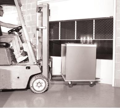
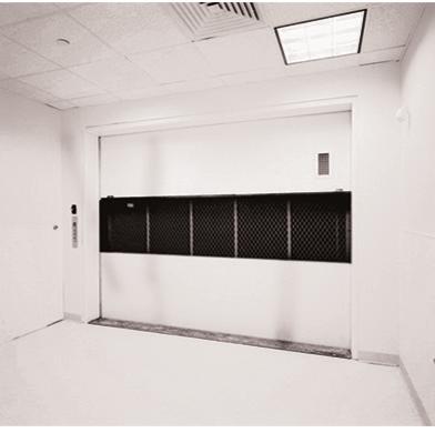
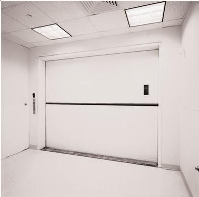
GUIDE 239 VSD VERTICALLY SERIAL CONTROLLER INSTALLATION & INTERFACE GUIDE. Guide No. SLIDING DOORS
|
|
|
- Bertina Sullivan
- 6 years ago
- Views:
Transcription
1 GUIDE CHANGE PARAMETER 53 TO 01 FOR SERIAL / WIRED COMMUNICATION VSD VERTICALLY SLIDING DOORS
2 Safety Warning Electrical Hazard Warning Symbol Failure to observe this warning could result in electrical shock or electrocution.! Operational Hazard Warning Symbol Failure to observe this warning could result in dangerous or unsafe conditions. Installation Note: This product should be installed and serviced by a qualified elevator technician familiar with its operation and hazards involved. Proper safety procedures must be followed when working with this controller during installation and with control under power. Proper shielding and grounding of this product is necessary to reduce the emissions of radio frequency interference (RFI) which may adversely affect sensitive electronic equipment. Electrical Wiring: Wire controller in accordance with the National Electrical Code, Canadian Electrical Code, European Norms and/or any other local codes that apply. General Contractor Note: A separate fuse disconnect switch is required for the door controllers. See job specific wiring diagrams for disconnect and fuse requirements. Enclosure Conduit Connections T&B Series 3651 Bonding & Grounding Wedge TYPE 1, 4 & 4X (Indoor Use Only) CAUTION Non-metallic enclosure does not provide grounding between conduit connections. Use grounding bushing and jumping wires. WARNING Do not mount controller on or above a combustible surface. The conduit hubs are to be connected to the conduit before being connected to the enclosure. To maintain the environmental rating of this enclosure, install in any openings only listed or recognized conduit hubs with the same environmental ratings as required, in compliance with the installation instructions of the device. Ground Bus Service Enclosure Service Equipment Bonding Jumper Grounding electrode conductor Grounding electrode Conductor enclosure (Rigid Metal Conduit or Intermediate Metal Conduit)
3 Contents Landing Door Controller Mounting 1 Landing Door Wiring Layout - Standard Operators 2 Landing Door Wiring Layout - Extra High Torque Operators 3 Landing Door Power Connections 4 Landing Door Encoder 5 Landing Door Operators - Standard Operators 6 Landing Door Operators - Extra High Torque 7 Landing Door Emergency Unlocking Device (EUD) 8 Landing Door Zone Switch (ZNS) 9 Serial Communication 10 Landing Door Hall Pushbuttons 11 Landing Door Light Curtain (Optional) 12 Car Door Installation and Wiring Layout 13 Car Door Power Connections 14 Car Door Encoder 15 Car Door Operator 16 Car Door Retiring Cam Motor 17 Serial Communication 18 Car Door Reversing Edge (optional) 19 Car Door Buzzer 20 Car Door Commissioning 21 Landing Door Commissioning 22 Landing and Car Door Operation and Testing 23 Sequence of Operation 23 Power up Mode / Loss of Power 23 Car Door Controller Input Connections 24 Car Door Controller Output Connections 25 Door Motion Profiles and Parameters 26 Troubleshooting - INDEPENDENT MODE 29 Troubleshooting - AUTOMATIC MODE 30 Troubleshooting - ELEVATOR INTERFACE OPERATION 31 Troubleshooting - Error Codes 32 Troubleshooting - Landing Door LCD 33 Troubleshooting - Car Door LCD 34 Technical Specifications 35 EC Declaration of Conformity 36
 Floors above lowest landing")
4 Landing Door Controller Mounting Mount the Landing door Controller to the hoistway wall. Use 1/4 inch hardware. Alternate Location Lowest Landing Recommended location Operator Encoder 4 Feet SLAVE Controller locations (where provided) Floors above lowest landing Recommended locations Alternate Location Interlock 1
5 Landing Door Wiring Layout - Standard Operators Power Operator Operator HOISTWAY TROUGH Serial Com Landing Door Junction Box or Trough Encoder Interlock EUD Hall Pushbuttons Door lock contact (DI) and Door Close Contact (DC) connect to elevator controller 2
6 Landing Door Wiring Layout - Extra High Torque Operators Power Operator Operator HOISTWAY TROUGH Serial Com Landing Door Junction Box or Trough Encoder Interlock Slave Controller EUD Hall Pushbuttons Door lock contact (DI) and Door Close Contact (DC) connect to elevator controller 3
7 Landing Door Power Connections Connect controllers in accordance with local electrical codes. Power branch circuit should come from machine room disconnect 10 amp circuit for each line of doors. Use #14AWG [2mm] copper wire for power connection. ON/OFF switch disconnects both lines If neutral is not used, main disconnect must break both lines. 1 Ø Power V AC 5.5A, 50/60 Hz WARNING HIGH VOLTAGES Read Safety Warning before attempting to use this controller GND L1 L2 / N CONDUIT AND SHIELD GROUNDING LUG Power! The enclosure supplied is nonmetallic and does not provide grounding between conduit connections. Use grounding bushings or jumper wires. 4
8 Landing Door Encoder Install and wire encoder same side as the controller. Do not extend the encoder wire. Shield White Yellow Green Brown GND COMM B A 12V ENCODER Landing Door Encoder 5
9 Landing Door Operators - Standard Operators Wire both door motors in parallel. Use #18AWG [1mm] wire in conduit for motor connection. Do not combine motor wires with control wires in same conduit. Note: Low speed winding is not used. Cap black wires separately (R4-R5). Landing Door Operator T1 R2 T1 R2 R3 R MOTOR 6
10 Landing Door Operators - Extra High Torque Use #18AWG [1mm] wire in conduit for motor connection. Do not combine motor wires with control wires in same conduit. Connect CAN and COMM wires between controllers. Notes 1. Low speed winding is not used. Cap black wires separately (R4-R5) 2. Use shielded wire or separate conduit for CAN bus connection slave Extra High Torque Landing Door Operator 1 T1 1 T1 2 R2 2 R2 3 R3 3 R3 MASTER CONTROLLER SLAVE CONTROLLER CANL CANH COMM Attention! Sheilded or separate conduit CANL CANH COMM 7
11 Landing Door Emergency Unlocking Device (EUD) The Emergency Unlocking Device is located on the landing side and contains a toggle switch which must be wired to the controller. NOTE: Only in jurisdictions not requiring unlocking devices, a jumper needs to but added in lieu of the EUD switch HDO HDC ZNS EUD STOP AUX1 AUX2 INPUT COM V- V+ Add jumper where EUD s are not provided Emergency Unlocking Device RESET SET The EUD indicator will flash ON all controllers in that channel to indicate there is a SET EUD at another floor. The EUD and input indicator 4 will go ON solid when the EUD switch is in the SET position (activated) for the door connected to that controller. For automatic door operation, ALL the EUD switches have to be in the RESET position as shown. (RESET is normally closed) Attention! Three quick buzzer outputs (from car controller) indicates the EUD is set on that channel Attention! When EUD is SET (at any floor) Doors on the same channel will not run. 8
12 Landing Door Zone Switch (ZNS) The landing door Zone Switch located in top of interlock box activates the controller for the Landing door at which the elevator car is located HDC HDO ZNS EUD STOP AUX1 AUX2 INPUT COM V- V+ Door Lock Contact (DI) connect to elevator controller The ZONE indicator will go ON solid when the ZNS contact is made for the door connected to that controller when elevator is at the landing with retiring cam extended ZONE turns OFF when the retiring cam lifts. When the retiring cam lifts the ZNS contact is open and the ZONE indicator turns off. The input indicator 3 will go ON solid when the ZNS contact is made for the door connected to that controller. Interlock Attention! The ZONE must be made for automatic door operation. If ZONE is not made doors will not run. 9
13 Serial Communication Use shielded (2) twisted pair RS-485 CABLE for A-A and B-B connections, and common connection. Front shown rear similar Note P53 must be set to 1 for serial communication on all controllers Top Floor (Front) Floor (Front) Bottom Floor (Front) L L WHEN UNTWISTING TWISTED PAIR, KEEP LEADS AS SHORT AS POSSIBLE. 10
14 Landing Door Hall Pushbuttons HALL DOOR OPEN BUTTON (HDO) 1 Where provided, wire landing station door OPEN pushbuttons as shown. When elevator car is within landing ZONE, pushbutton inputs will be transmitted to the Car Door controller for connection to elevator control. HALL DOOR CLOSE BUTTON (HDC) 2 Where provided, wire landing station door CLOSE pushbutton as shown. When elevator car is within floor ZONE, pushbutton inputs will be transmitted to the Car Door controller for connection to elevator control. DOOR STOP BUTTON (STOP) 5 Where provided, wire landing station door STOP pushbutton as shown. The door STOP button should be normally open (NO). If normally closed (NC) set parameter 96 to 01. See DOOR STOP output for connection to elevator control HDO HDC ZNS EUD STOP AUX1 AUX2 INPUT COM V- V+ OPEN CLOSE STOP The input indicators 1 2 and 5 will go ON when the pushbutton is activated for the door connected to that controller. 11
15 Landing Door Light Curtain (Optional) Install and wire Landing Door Light Curtain where provided. Note: V+ to RE contact must close when beams are blocked To landing box or trough Light Curtain Controller Power RE V+ 8 See job specific wiring schematic Landing Door Landing Door Light Curtain 12
16 Car Door Installation and Wiring Layout Mount the Car Door Controller to the car door rail spreader. Mount to same side as the Encoder. Use 1/4 Hardware. Car Door Motor Spreader Car Door Controller Car Door Buzzer Encoder Reversing Edge Car Top Junction Box Retiring Cam Motor 13
17 Car Door Power Connections Connect controllers in accordance with local electrical codes. Power branch circuit should come from machine room disconnect 10 amp circuit for each line of doors. Use #14AWG [2mm] copper wire for power connection. ON/OFF switch disconnects both lines If neutral is not used, main disconnect must break both lines. 1 Ø Power V AC 5.5A, 50/60 Hz WARNING HIGH VOLTAGES Read Safety Warning before attempting to use this controller GND L1 L2 / N CONDUIT AND SHIELD GROUNDING LUG Power! The enclosure supplied is nonmetallic and does not provide grounding between conduit connections. Use grounding bushings or jumper wires. 14
18 Car Door Encoder Install and wire encoder. Do not extend the encoder wire. Shield White Yellow Green Brown GND COMM B A 12V ENCODER Car Door Encoder 15
19 Car Door Operator Use #18AWG [1mm] wire in conduit for motor connection. Do not combine motor wires with control wires in same conduit. Note: Low speed winding is not used. Cap black wires separately (T8-T9). Car Door Operator T1 1 T6 2 T7 3 On large car doors where provided wire opposite car door operator in parallel. 16
20 Car Door Retiring Cam Motor Use #18AWG [lmm] wire in conduit for motor connection. Do not combine motor wires with control wires in same conduit. Attention! 220 Volt 3 Ø Retiring Cam Motors Only Attention! For 110 Volt 1 Ø Retiring Cam Motors for battery lowering see elevator control panel Retiring Cam Motor Y1 4 Y2 5 Y3 6 Where provided on wide landing doors, wire opposite side retiring cam motor in parallel. 17
21 Serial Communication Use shielded twisted pair (STP) travel cable for A-A and B-B connections use #18 AWG (1mm) for common connection. Note P53 must be set to 1 for serial communication on all controllers Front shown rear similar Car Door (Front) L L WHEN UNTWISTING TWISTED PAIR, KEEP LEADS AS SHORT AS POSSIBLE. 18
22 Car Door Reversing Edge (optional) Wire reversing edge as shown where provided. RE V+ 8 Car Door Panel Reversing Edge 19
23 Car Door Buzzer Install and wire door close warning buzzer as shown. See parameter 94 for constant or pulsing tone. BUZZER - + RED BLACK BUZZER Attention! Warning Buzzer is mounted in Auxiliary strobe controller (27465) if strobe light is provided 20
24 Car Door Commissioning Make sure all Landing Doors and Car Doors are adjusted and run freely by hand in the door guides without binding or sticking. 1. Turn power ON AUTO IND 2. Set AUTO<>IND switch to IND OPEN CLOSE RET CAM _ + ENTER 3. Using the OPEN, CLOSE and RETCAM cam buttons, ensure the car door operator(s) and retiring cam motor(s) are phased for correct rotation. If a motor rotates in the wrong direction, switch any two of the three motor wires 4. To begin, cycle through parameters by pressing the - & + buttons. Once the desired parameter is displayed, press the ENTER button to access the setting for that parameter. Change the setting by pressing the - & + buttons. Once the desired setting is displayed, press the ENTER button to save the setting. Parameters can only be modified in IND mode. 5. Change parameter 53 to 01. The LCD display should NOT have a Channel # showing. Tweaks Tweaks AUTO CLOSE IND 6. Change parameter 02 to Cd setting. The LCD display should now read CAR DOOR. 7. Change parameter 10 to Lr setting. Press ENTER to begin learn cycle. Prior to learn, car door can be in any position. The learn cycle will fully close and then fully open. Once the car door is fully open, the learn cycle is complete and the flashing LEARN indicator on the LCD will turn off. 8. Press and hold the CLOSE button to close the door. 9. Set AUTO<>IND switch to AUTO. If car door stalls before learn is complete, set parameter 12 to HD. Re-run the learn cycle. Adjust speeds to suit to ensure car door does not slam. If car door stalls during operation (normal operation or nudging), set parameter 12 to HD. Adjust speeds to suit to ensure car door does not slam. If retiring cam top assembly does not completely lift retiring cam bottom assembly, set parameter 70 to
25 Landing Door Commissioning Ensure Landing Door interlock is mechanically unlocked. Ideally car is level at floor with retiring cam extended Ensure all EUD switches are set to the SET position 1. Turn power ON AUTO _ OPEN CLOSE IND + ENTER 2. Set AUTO<>IND switch to IND 3. Using the OPEN and CLOSE buttons, ensure the landing door operators are phased for correct rotation. If a motor rotates in the wrong direction, switch any two of the three motor wires. 4. To begin, cycle through parameters by pressing the - & + buttons. Once the desired parameter is displayed, press the ENTER button to access the setting for that parameter. Change the setting by pressing the - & + buttons. Once the desired setting is displayed, press the ENTER button to save the setting. Parameters can only be modified in IND mode. 5. Change parameter 53 to 01. The LCD display should NOT have a Channel # showing. 6. Change parameter 03 to match the channel of the adjacent car door. All the landing doors for the front line must have the same channel as the front car door. The LCD display will show what channel has been selected. If you have Extra High Torque Door Operators (see pg 7) Set Slave controller to SL, no further commissioning of the slave controller is required. Commission the associated master controller normally. 7. Change parameter 04 to address the landing door. Use ADDRESS 01 for the lowest door in a line of doors. Each additional landing door in line should be addressed in sequence (01, 02, 03 Etc). The LCD display will show what address has been selected. 8. Change parameter 10 to Lr setting. Press ENTER to begin learn cycle. Prior to learn, Landing Door can be in any position. The learn cycle will fully close and then fully open. Once the Landing Door is fully open, the learn cycle is complete and the flashing LEARN indicator on the LCD will turn off. 8. Press and hold the CLOSE button to close the door. CLOSE AUTO IND 9. Set AUTO<>IND switch to AUTO. 22
26 Landing and Car Door Operation and Testing With elevator control inputs removed, test the following Sequence of Operation using the OPEN, CLOSE and RETCAM buttons. OPEN CLOSE AUTO RET CAM _ IND ENTER Sequence of Operation + 1. Remove elevator control inputs to DO, DC, SE, DCM 2. Make sure the controllers are set to AUTO 3. Use the OPEN, CLOSE and RETCAM buttons to test the door and car door and retiring cam sequence of operation. Note 1 Landing door and car door operation will be simultaneous when DCM 4 input is used. Note 2 For USER 1/2 options see parameter 65/85 Power up Mode / Loss of Power After power-up with the elevator car at a landing, upon automatic initiation of either open or close, the landing door and car door will operate at learn speed until the final open or closed position is reached and held for 1 second. The control will reset the learned profile and initiate DOOR OPEN or DOOR CLOSED output. All unzoned landing door controllers will power up to normal profile See Parameter 93. Attention! Landing door and Car door settings and speed profiles are retained by the controller when power is removed. It is not necessary to relearn the opening. 23

27 Car Door Controller Input Connections Control Interface Inputs to the car door controller are the only interface to the elevator control for door operation. Note: front and rear inputs are completely separate. INPUT COM Add jumper to the INPUT COM from V- when car car door controller V+ is used for the input voltage. Note: where elevator control voltage is used, connect INPUT COM to elevator controller according to elevator control prints. Do not use V+ or V-. DO - Door Open 2 Constant signal required to open doors DC - Door Close 2 Constant signal required to close doors SE - Nudging 3 Constant signal required with door close for car door slow speed closing in fire service phase 1 recall. DCM - Fast Open / Close 4 Constant signal required with door CLOSE for landing door and car door simultaneous operation. RC - Retiring Cam 5 Input required to lift cam and move car. Signal should be low whenever car is stopped. BUZZ - Close Warning Buzzer 6 Input required 5 seconds before automatic door close and until doors are fully closed. AUX2-7 For input options see parameters 65/85/88 RE - Reversing Edge 8 LCD INPUT INDICATORS D0 DC SE DCM RC BUZZ AUX2 INPUT COM V- V+ CLOSE BUZZER RETIRING CAM FAST OPEN/CLOSE NUDGING DOOR CLOSE ELEVATOR CONTROLLER DOOR OPEN 24
28 Car Door Controller Output Connections HALL OPEN - output relay Contact closes when zoned hall door open button is pressed. HALL CLOSE - output relay Contact closes when zoned hall door close button is pressed. DOOR STOP - output relay Normally open contact closes and normally closed contact opens, when zoned hall door stop button is pressed or doors are stuck. REVERSING EDGE - output relay Output - normally open contact closes and normally closed contact opens when edge is activated. DOOR OPEN - output relay Normally open contact closes and normally closed contact opens when landing door and car door are open. DOOR CLOSED - output relay Normally open contact closes and normally closed contact opens when landing door and car door are closed Attention! See Parameter 97 for powerup mode relay condition. HALL OPEN USER 1 - output relay Default: Normally open contact closes and normally closed contact opens when both landing door and car door are 3/4 open. Option: see parameter 65 HALL CLOSE COM1 NO NO NC NO DOOR OPEN DOOR CLOSE DOOR STOP HALL BUTTONS USER 2 - output relay Normally open contact closes and normally closed contact opens when both landing door and car door are 3/4 closed. Option: see parameter 85 DOOR STOP REVERSING EDGE NC COM2 NO REVERSING EDGE OUTPUT NOTE Elevator controller interface connections to the Car Door Controller ONLY. No connection to landing door controller. USER 2 USER 1 DOOR CLOSED DOOR OPEN RE V+ + - REVERSING EDGE INPUT BUZZER NO NC NO NC USER 2 USER 1 COM4 NO NC DOOR CLOSED NO DOOR OPEN NC COM3 CANL CANH COM 25
29 Door Motion Profiles and Parameters Parameter Description Range Landing Pre Set Car Pre Set 1 Reset Overload (00 = Do not reset, 01 = Reset) Controller Type: Car Door, Landing Door, Slave Cd,Ld,SL Ld Ld 3 Channel: set a unique Channel for each line of doors Floor: set a unique Floor address for each Landing Door (note: 00 is not a valid address) N/A 10 Learn Command: used to learn the opening Lr or Learn Speed: set learn and power-up speed Car Door Duty: increase the car door duty Sd = Standard Duty, Hd = Heavy Duty Sd-Hd N/A Sd 23 Open High Speed: set the opening high speed Open Deceleration Zone: set distance of deceleration ramp Open Low Speed: set low speed open Open Low Speed Zone Open Hold Torque: set the hold open torque Close High Speed: set the closing high speed Close High Speed Torque Limit Close Nudging Speed N/A Close Nudging Speed Torque Limit N/A Close Deceleration Zone: set distance of deceleration ramp Close Low Speed: set low speed close Close Low Speed Zone: set distance of low speed zone Close Hold Torque: set the hold close torque
30 Parameter Description Range Landing Pre Set Car Pre Set 50 Control Interface: set discrete or CAN bus interface 00 = discrete, 01 = CAN N/A Car Door Designation: 00 = Front, 01 = Rear (only displayed if Parameter 50 = 01) N/A CmcMedia: 00 = RF, 01 = Wired RS_ USING AS REPLACEMENT CONTROLLER If Parameter 80 is 18 or lower change Parameter 54 to Lost Communication Reaction Time 04 = 0.4 sec 05 = 0.5 sec = 1.8 sec 60 Deceleration rate Acceleration rate USER 2 Close Limit: set position of the user door close limit USER 1 Open Limit: set position of the user door open limit User Limits Setting: 00 = landing door USER limit + car door USER limit sets USER relay output on car door controller 01 = car door USER limit sets USER relay output on car door controller N/A USER 1 options 00 = USER1 POSITION 01 = USER2 POSITION 02 = ZONE 03 = BUZZ / STROBE = DOOR OPEN POSITION 05 = DOOR CLOSED POSITION 06 = AUX2 INPUT 70 Retiring Cam Ramp Up Time (0.1 second increments) N/A Retiring Cam Ramp Down Time (0.1 second increments) N/A Retiring Cam Duty Control 00 = Disabled (contact Peelle if used) 01 = 50% Duty N/A = 75% Duty 80 Software Version (read only) 2 digits Software Version Software Version 81 Radio Strength Motor Duty Control 00 = Disabled (contact Peelle if used) 01 = Standby Duty = Increased Duty 83 Motor Overload Control 00 = Disabled (contact Peelle if used) 01 = Default Threshold = Increased Threshold 84 Drive Over Temperature Control 00 = Disabled (contact Peelle if used) 01 = Default Threshold = Increased Threshold 85 USER 2 options 00 = USER 2 POSITION 01 = USER 1 POSITION 02 = ZONE 03 = BUZZ / STROBE 04 = DOOR OPEN POSITION 05 = DOOR CLOSED POSITION 06 = AUX2 INPUT
31 Parameter Description Range Landing Pre Set Car Pre Set 86 Retiring Cam Startup Torque N/A Car Door Aux2 Input Option 00 = Disabled N/A = Independent Car Door Operation with input ON 89 Momentary Door Open / Door Close Option 00 = Constant DO and DC operation N/A = Momentary DO and DC operation 93 Power Up landing door speed (unzoned only) 00 = learn speed until final open/close limit N/A 01 = normal profile speed 94 Buzzer Output: 00 = Pulsing, 01 = Continuous Close Input Buzzer Control: 00 = Disabled, 01 = Enabled Hall Stop Button Input: 00 = Normally Open, 01 = Normally Closed N/A 97 Power-Up Settings: 01 Door Closed = 1, Door Open = 1; 02 Door Closed = 1, Door Open = 0; 03 Door Closed = 0, Door Open = 0; If zoned, both Door Closed and Door Open = 0, regardless of selection. Condition of outputs is established automatically after opening or closing cycle Show Cycle Counter 6 digits Cycle Counter Cycle Counter 99 Restore Factory Default Settings 00 Exit without saving 01 Restore all Motor parameters (#20 97) 02 Restore all parameters (#2 97) N/A Not available Speeds are expressed as a percentage of full speed. Zone is expressed as a percentage of total travel. Torque is expressed as a percentage of nominal voltage for corresponding speed. 28
32 Troubleshooting - INDEPENDENT MODE PEELLE ONLY OPERATION - USED FOR COMMISSIONING AND INDIVIDUAL LANDING/CAR DOOR OPERATION (AUTO-IND slider switch set to IND) Problem Possible Cause Action No operation from OPEN/CLOSE pushbutton No operation from RETCAM pushbutton Slow speed Landing/Car Door operation only Landing/Car door runs for 12 then stops AUTO-IND slider not set to IND Wiring problem to Landing Door motor output or Car Door selector relay output Flashing LCD OVERLOAD icon Constant LCD OVERLOAD icon Controller type not set to Car Door (CD) Wiring problem to Car Door selector relay output LCD LEARN flashing Encoder set screw loose Encoder wiring problem Set AUTO-IND slider to IND See page 6 for Landing Door motor wiring See pages 15 & 16 for Car Door/Retiring Cam motor wiring Duty timer for motor has been exceeded. Cool down period required for motor regeneration. If condition persists, increase duty timer. See parameters P72 & P82. Note: increasing duty timer may shorten motor life Check Landing Door motor output or Car Door selector relay output for short circuit to ground See page 6 for Landing Door motor wiring See pages 15 & 16 for Car Door/Retiring Cam motor wiring Acknowledge OVERLOAD by setting parameter P01 to 01 Ensure parameter P02 is set to CD See pages 15 & 16 for Car Door/Retiring Cam motor wiring Operational profile not learned. Set parameter P10 to Lr to initiate learn sequence Ensure set screw is tight on encoder shaft See page 5 for Landing Door encoder wiring See pages 14 for Car Door encoder wiring Move door manually and check that encoder count on LCD is changing Retiring Cam not fully pulling back Mechanical problem with bottom assembly (face) Ensure bottom assembly moves freely on pivot pins Ensure connecting rod is parallel to bottom assembly (face) and top assembly (motor) Mechanical problem with top assembly (motor) Ensure pulley belt has 3/4 of deflection Mechanical problem with full assembly Ensure when pulling back that pickup arm on top assembly starts at 6 o clock and rotates towards middle of car to either 9 o clock or 3 o clock (depending on rotational direction) 29
33 Troubleshooting - AUTOMATIC MODE PEELLE ONLY OPERATION - USED FOR COMBINED LANDING AND CAR DOOR OPERATION (AUTO-IND slider switch set to AUTO) Problem Possible Cause Action No operation from OPEN/CLOSE pushbutton AUTO-IND slider not set to AUTO Elevator not in Landing Door zone LCD ZONE icon not on at either Landing Door controller or corresponding Car Door controller LCD ANTENNA icon not on (or flashing) at zoned Landing Door controller or corresponding Car Door controller LCD EUD icon on (or flashing) at Landing Door controller and flashing at corresponding Car Door controller LCD MULTIZONE icon on at Landing Door controller and corresponding Car Door controller Flashing LCD OVERLOAD icon Constant LCD OVERLOAD icon Set AUTO-IND slider to AUTO All controllers must be set to AUTO. Ensure retiring cam bottom assembly is on Landing Door roller arm Ensure Input 3 is on at Landing Door controller. See page 9. Ensure Landing Door channel matches Car Door channel. Adjust parameter P03 if necessary Ensure Landing Door address is unique and not set to 00. Adjust parameter P04 if necessary Constant LCD EUD icon = EUD is in set position at current landing Flashing LCD EUD icon = EUD is in set position at another landing on the same channel See page 8. Check all interlock zone micro switches. Only one zone micro switch can be on at a time on one channel. Duty timer for motor has been exceeded. Cool down period required for motor regeneration. If condition persists, increase duty timer. See parameters P72 & P82. Note: increasing duty timer may shorten motor life Check Landing Door motor output or Car Door selector relay output for short circuit to ground See page 6 for Landing Door motor wiring See pages 15 & 16 for Car Door/Retiring Cam motor wiring Acknowledge OVERLOAD by setting parameter P01 to 01 30
34 Troubleshooting - ELEVATOR INTERFACE OPERATION Problem Possible Cause Action Elevator controller is sending outputs to Peelle controller but no Landing/Car Door operation in open or close direction Are LCD input icons on Car Door controller? If not check the folowing: If Peelle power is used to power Peelle inputs, missing jumper from Input Com terminal to V terminal on Car Door controller If external power is used to power Peelle inputs, missing external power reference wire on Input Com terminal on Car Door controller Landing Door stop input on Landing/Car door stopped before final open/close Add jumper from Input Com to V-. See page 22 Ensure external power reference is wired to Input Com. See page 22 Note: ensure no connections to Peelle V+/V- Ensure parameter P50 is set to 00. Ensure input 5 is off on Landing Door controller. See page 10 See Automatic Mode chart Door may be mechanically obstructed. Fix obstruction. If there is not enough power in slow speed for final open or final close, increase the following parameter(s) in multiples of 5 until fixed: Open direction - P27 Elevator controller is sending outputs to Peelle controller but no Landing/Car Door operation in close direction Light curtain obstructed Close direction - P48 Check light curtain alignment 31

35 Troubleshooting - Error Codes If the setting is flashing from encoder count (5 digits) to and error code (4 digits) refer to the following. How to read Example: Car Door Error The first two digits are the sum of the first four possible errors. 06 = 02 (car door motor run error) + 04 (car motor over duty) The last two digits are the sum of the last four possible errors. 10 = 02 (EUD error) + 08 (lost zone) Car door error codes - last two digits 01 - Not used 02 - EUD error 04 - Multi Zone error 08 - Lost zone Car door error codes - first two digits 01 - Landing door motor run error 02 - Car door motor run error 04 - Car motor over duty 08 - retiring cam motor over duty Landing door error codes - last two digits 01 - Not used 02 - EUD input set 04 - Multi Zone error 08 - Lost zone Landing door error codes - first two digits 01 - Landing door motor run error 02 - Not used 04 - Landing door motor over duty 08 - Not used To clear error codes cycle the AUTO-IND slider switch AUTO IND 32

36 Troubleshooting - Landing Door LCD Radio Communication Antenna is ON solid when elevator is at a floor and door is ZONED Antenna is ON solid when EUD is SET whether door is ZONED or not Antenna is OFF when elevator is not ZONED For intermittent flashing in ZONE adjust channel selection Multiple Zone MULTIZONE indicator is shown when two or more landing door controllers are ZONED on the same channel Check zone switches and ZNS inputs at landings Number Display Number display show encoder count (door position) Approximately 0-50 for landing door closed position Full count for open position May flash fault codes for Peelle Use Motor Overload / Over Duty OVERLOAD is ON solid when over current exists at motor output Check for shorts on motor line Check for shorts to ground Reset of overload is required; set parameter 01 to 01 and press ENTER to clear (must go to IND mode) OVERLOAD is flashing when motor run time exceeds duty Let motor reset for 5 minutes Over Duty does not require reset Landing Zone Zone is ON solid when elevator is at a floor with retiring cam extended and door unlocked Input indicator 3 ZNS is ON when door is ZONED Zone and 3 are OFF when doors are locked and / or car is moving between floors Doors will not run if ZONE is not made Check ZNS and zone switch Input Indicators 1 HDO - Hall door open button 2 HDC - Hall door closed button 3 ZNS - Floor Zone switch 4 EUD - Emergency Unlocking Device 5 STOP - hall door stop button 6 AUX1 - Not Used 7 AUX2 - Not Used 8 RE - Hall door light curtain input (where provided) Emergency Unlocking Device EUD is ON solid when EUD is SET at that floor Input indicator 4 is ON when EUD is SET at that floor EUD is flashing when EUD is SET at another floor on same channel Doors will not run if any EUD is SET on the same channel Door Stop Sign Door Stop Sign is ON whenever motors are not running Door Stop Sign is OFF when power is being applied to motors 33

37 Troubleshooting - Car Door LCD Radio Communication Antenna is ON solid when elevator is at a floor and door is ZONED Antenna is OFF when elevator is travelling Antenna is Flashing Constant when elevator is not ZONED For intermittent flashing in ZONE adjust channel selection Multiple Zone MULTIZONE error is shown when two or more landing door controllers are ZONED on the same channel ZONED floor addresses are shown in Number Display Check ZONE switches and ZNS inputs at landings Number Display Number display show encoder count (car door position) Approximately 0-50 for car door closed position Full count for open position Will show floor addresses in MULTIZONE error Shows floor addresses when and EUD is SET May flash fault codes for Peelle Use Input Indicators 1 DO - Door open command from elevator 2 DC - Door closed command from elevator 3 SE - Close nudging command from elevator 4 DCM - Fast close command from elevator 5 RC - Retiring cam command from elevator 6 BUZZ - Close warning buzzer command from elevator 7 AUX2 - Not Used 8 RE - Reversing edge input from car door 34 Motor Overload / Over Duty OVERLOAD is ON solid when over current exists at motor output Check for shorts on motor line Check for shorts to ground Reset of overload is required; set parameter 01 to 01 and press ENTER to clear (must go to IND mode) OVERLOAD is flashing when motor run time exceeds duty Let motor reset for 5 minutes Over Duty does not require reset Emergency Unlocking Device EUD is flashing when an EUD has been SET EUD is OFF when all landing doors have been RESET Floor addresses where EUD is SET are shown in the Number Display Doors will not run if any EUD is SET on the same channel Landing Zone Zone is ON solid when elevator is at a floor with retiring cam extended and door unlocked Zone is OFF when all doors are locked and / or car is moving between floors Doors will not run if ZONE is not made Check ZNS and zone switch Door Stop Sign Door Stop Sign is ON whenever motor is not running Door Stop Sign is OFF when power is being applied to motor
38 Technical Specifications Technical Data Specification Input Power 240V, 1.3 kw Supply Voltage V, 1 Ø AC, 50/60Hz Output Power 0-230V, 3 Ø AC, 4.2A, 0-60Hz Output Motor 0.75 kw (1 HP) Digital Inputs 8 provided, 12-30V, AC or DC Encoder Input Incremental, NPN, 12VDC, 120 PPR Relay Outputs 8 provided, Form C, 10A, 125VAC Input Indicators LCD screen Output Indicators LED Enclosure Protection NEMA 1,4,4X (indoor use only) - IP 65 Temperature 40 Deg C Max Dimensions 200mm x 430mm x 85mm (W x H x D) Mounting Method 4 screw holes on outside perimeter Equipment Class Digital Transmission System Wireless Network LR-WPAN standard Wireless Frequency 2.4GHz Wireless Output Watts Wireless Range 100m floor-to-floor up to 99 floors User Interface On board pushbuttons with visual display Visual Display 50mm x 40mm back-lit LCD Parameters User adjustable with factory presets and defaults Learn Adjustment Automatic by user parameter Landing Door Address User selectable parameter Car or Landing Door Type User selectable parameter Fail Safe Condition Door Stop if communication lost.31 [8] [432] 3.26 [83] 8.00 [203] 6.75 [171] Standards Elevators and Lifts ASME-A17.1/CSA-B44 ASME-A17.5/CSA-B44.1 EN 81 EN and EN12016 Telecommunication FCC Industry Canada R&TTE Directive [400] Certification ETL Listing and Certification Mark FCC Grant of Equipment Authorization Industry Canada Certificate of Acceptance Declaration This device complies with part 15 of the FCC rules. Operation is subject to the following two conditions: (1) the device may not cause harmful interference, and (2) the device must accept any interference received, including interference that may cause undesired operation. Modifications not expressly approved by The Peelle Company Ltd. could void the user s authority to operate the equipment under FCC rules..40 [10] 35
39 EC Declaration of Conformity Manufacturer: The Peelle Company Ltd. 195 Sandalwood Pkwy W. Brampton, Ontario L7A 1J6 CANADA We, The Peelle Company Limited of Brampton, Ontario, declare that the product designated below complies with the relevant fundamental requirements of Article 3 of the Lifts directive 95/16/EC and Article 3 of the R&TTE Directive 1999/5/EC, insofar as the product is used as intended and the following standards applied: Product: Wireless Freight Door Controller, 2.4GHz, Transceiver Module Manufactured by: The Peelle Company Ltd. Trade mark: Peelle Model: WFDC Car Door, WFDC Landing Door Environment of use: Residential, commercial and light industry Standards: -Lifts EN 81: Safety rules for the construction and installation of lifts EN 12015: Electromagnetic compatibility Emissions EN 12016: Electromagnetic compatibility Immunity -Telecommunication EN 50371, EN , EN , EN and EN Date of issue: AUG 2014 Place of issue: Brampton, Ontario, CA Steven Reynolds, P.Eng. Director of Engineering 36

40
224-EN WIRELESS CONTROLLER INSTALLATION & INTERFACE GUIDE. Guide No. 224-EN USING AS REPLACEMENT CONTROLLER
 INSTALLATION & INTERFACE GUIDE USING AS REPLACEMENT CONTROLLER Confirm software version on existing controllers See Parameter 80 If Parameter 80 is 18 or lower change Parameter 54 to 1 Guide No. Contents
231.V1 GUIDE VSD. CONTROL SYSTEM & INTERFACE GUIDE C/W TDP (Total Door Protection) Dual Light Curtains
 Dual Light Curtains") I CAR GATES I CAR ENCLOSURES GUIDE FREIGHT DOORS INTERFACE GUIDE C/W TDP (Total Door Protection) Dual Light Curtains 202 Standard Operation 202 Slave Mode 201 Sequence of Operations VSD VERTICALLY SLIDING
I CAR GATES I CAR ENCLOSURES GUIDE FREIGHT DOORS INTERFACE GUIDE C/W TDP (Total Door Protection) Dual Light Curtains 202 Standard Operation 202 Slave Mode 201 Sequence of Operations VSD VERTICALLY SLIDING
GUIDE 200.V2 VSD VERTICALLY CONTROL SYSTEM & INTERFACE GUIDE. 202 Standard Operation 202 Slave Mode 201 Sequence of Operations
 THE PEELLE COMPANY FREIGHT DOORS I CAR GATES I CAR ENCLOSURES GUIDE 200.V2 CONTROL SYSTEM & INTERFACE GUIDE 202 Standard Operation 202 Slave Mode 201 Sequence of Operations VSD VERTICALLY SLIDING DOORS
SYMBOL LEGEND DANGER WARNING NOTE THIS INDICATES DANGER TO THE LIFE AND HEALTH OF THE USER IS APPROPRIATE PRECAUTIONS ARE NOT TAKEN
 SYMBOL LEGEND DANGER THIS INDICATES DANGER TO THE LIFE AND HEALTH OF THE USER IS APPROPRIATE PRECAUTIONS ARE NOT TAKEN WARNING THIS WARNS THAT MATERIALS MAY BE DAMAGED IF APPROPRIATE PRECAUTIONS ARE NOT
Product Overview. Product Identification. Amps One CT Two CTs Three CTs
 AH06 (optional mounting bracket for small, medium, and large CTs) DANGER HAZARD OF ELECTRIC SHOCK, EXPLOSION, OR ARC FLASH Follow safe electrical work practices. See NFPA 70E in the USA, or applicable
INSTALLATION INSTRUCTIONS AND OPERATION MANUAL
 INSTALLATION INSTRUCTIONS AND OPERATION MANUAL UL325-2010 Compliant Commercial and Industrial Door Operator Logic Control Continuous Duty IMPORTANT INSTALLATION INSTRUCTIONS WARNING To reduce the risk
SAFE AND SECURE EXTREME R MOTOR OWNER'S MANUAL MODEL PRO-FDG FOR TECHNICAL SUPPORT PLEASE CALL 1-(855) OPERATOR SERIAL#
 OPERATOR SERIAL#") SAFE AND SECURE EXTREME R MOTOR OWNER'S MANUAL MODEL PRO-FDG FOR TECHNICAL SUPPORT PLEASE CALL 1-(855) 594-4969 3121B(4) ECN 1288 BY TG 2/6/15 OPERATOR SERIAL# PRO-FDG MOTOR OPERATORS MOTOR OWNER'S MANUAL
SAFE AND SECURE EXTREME R MOTOR OWNER'S MANUAL MODEL PRO-FDG FOR TECHNICAL SUPPORT PLEASE CALL 1-(855) 594-4969 3121B(4) ECN 1288 BY TG 2/6/15 OPERATOR SERIAL# PRO-FDG MOTOR OPERATORS MOTOR OWNER'S MANUAL
A419 Series Electronic Temperature Controls with NEMA 1 or NEMA 4X Watertight Enclosures
 Installation Instructions Issue Date April 8, 2008 A419 Series Electronic Temperature Controls with NEMA 1 or NEMA 4X Watertight Enclosures Application IMPORTANT: The A419 Series Electronic Temperature
INSTALLATION INSTRUCTIONS AND OPERATION MANUAL
 INSTALLATION INSTRUCTIONS AND OPERATION MANUAL NEMA 4X UL325-2010 Compliant Commercial and Industrial Door Operator Logic Control Continuous Duty IMPORTANT INSTALLATION INSTRUCTIONS WARNING To reduce the
Gate & Door Controller with LCD and Intelligent Technology
 2nd Edition Gate & Door Controller with LCD and Intelligent Technology 24Sv1 and 12Sv1 Motor Controllers Setup and Technical information for single motor controller for gates & doors Includes latest Intelligent
EXTREME R MOTOR OWNER'S MANUAL
 EXTREME R MOTOR OWNER'S MANUAL 2 HP, 3 HP & 5 HP WITH SELF-ENGAGING CHAIN HOIST FOR TECHNICAL SUPPORT PLEASE CALL 1-(855) 594-4969 3137B(0) ECN 1313 BY JM 7/9/15 OPERATOR SERIAL# PRO-FDG MOTOR OPERATORS
Trademarks All trademarks or registered product names appearing in this document are the exclusive property of the respective owners.
 Copyright Copyright 2006, Ltd. All Rights Reserved. This document may not be reproduced, electronically or mechanically, in whole or in part, without written permission from Ltd. Trademarks All trademarks
2 WAY REMOTE STARTER & ALARM SYSTEM INSTALLATION GUIDE FCC ID NOTICE
 REV. ARS. WAY REMOTE STARTER & ALARM SYSTEM INSTALLATION GUIDE FCC ID NOTICE This device complies with Part 5 of the FCC rules. Operation is subject to the following conditions:. This device may not cause
ASSA ABLOY Series Power Operator Installation and Instruction ASSA Manual ABLOY ASSA ABLOY
 00 Series Power Operator Installation and Instruction ASSA Manual ABLOY Item No. Description Motor (00M) Cover (00COV) Control Inverter (00IN) Power Supply VDC (00PS) Track Assembly (0-) / Replacement
VP-6124/VP-6124-E 24 VOLT DC SWITCHING POWER SUPPLY
 Issue 6 VP-6124/VP-6124-E 24 VOLT DC SWITCHING POWER SUPPLY INTRODUCTION These instructions provide the specifications, installation and maintenance information for the VP-6124 and VP-6124-E, 24Volt Power
ADJUSTABLE FREQUENCY CRANE CONTROLS
 IMPULSE G+ MINI ADJUSTABLE FREQUENCY CRANE CONTROLS The IMPULSEG+ Mini from Magnetek continues our history of providing the most reliable and cost-effective adjustable frequency crane controls available.
- Wiring Brochure Zone Manager 336
 - Wiring Brochure W 336 12/08 1 Information Brochure Choose controls to match application Application Brochure Design your mechanical applications 2 3 Rough-in Wiring Rough-in 4 Wiring Brochure Wiring
- Wiring Brochure Zone Manager 335
 - Wiring Brochure W 335 12/08 1 Information Brochure Choose controls to match application 2 Application Brochure Design your mechanical applications Rough-in Wiring Rough-in wiring instructions 3 4 Wiring
ASSA ABLOY Series Power Operator Installation and Instruction ASSA Manual ABLOY ASSA ABLOY
 0 Series Power Operator Installation and Instruction ASSA Manual ABLOY Item No. Description Motor (00M) Cover (00COV) Control Inverter (00IN) Power Supply VDC (00PS) / Replacement Motor Key (00KEY) Rod
MB A 12V/24V DC PROGRAMMABLE DUAL BATTERY ISOLATOR
 MB-3688 120A 12V/24V DC PROGRAMMABLE DUAL BATTERY ISOLATOR User Manual Warning and Precautions MB-3688 is built with corrosion resistant material and the main electronic assembly is well sealed inside
IRRIGATION 810-3T-PLUS TRANSMITTER GUIDE
 IRRIGATION 810-3T-PLUS TRANSMITTER GUIDE Pg. 2 HOT SHOT OVERVIEW 3 STANDARD OPERATION MODE 4 HOW TO CONTROL AND SHARE MULTIPLE S 5 TRANSMITTER FUNCTION SWITCH SETTINGS 6 OPERATING THE TEST BEACON 7 OPERATING
OPERATING INSTRUCTIONS FOR SLIDING DOOR RETROFIT CONTROLLER DC-02
 OPERATING INSTRUCTIONS FOR SLIDING DOOR RETROFIT CONTROLLER DC-02 1. INTRODUCTION 2. SAFETY INSTRUCTIONS 3. SPECIFICATION 4. OPERATING INSTRUCTIONS AND CONTROL FUNCTIONS 5. SET UP PROCEDURE 6. CONNECTIONS
MODEL WBG WISHBONE BARRIER GATE OPERATOR
 TABLE OF CONTENTS MODEL WBG WISHBONE BARRIER GATE OPERATOR Important Safety Information.....3 System Designer Safety Instructions.......4 Installer Safety Instructions........ 5 End User Safety Warnings...-
User s Manual. ACS550-CC Packaged Drive with Bypass Supplement for ACS550-01/U1 Drives User s Manual
 User s Manual ACS550-CC Packaged Drive with Bypass Supplement for ACS550-01/U1 Drives User s Manual ii ACS550-CC Packaged Drive with Bypass ACS550 Drive Manuals GENERAL MANUALS ACS550-01/U1 Drives User's
ARCHITECTURAL CONTROL SYSTEMS, INCORPORATED ST. LOUIS, MISSOURI
 II 1400-6 ARCHITECTURAL CONTROL SYSTEMS, INCORPORATED ST. LOUIS, MISSOURI ACSI 1426-04-AO ELECTRIC LATCH RETRACTION CONTROLLER INSTALLATION INSTRUCTIONS I.D. 1092, REV. C INSTALLATION For C-UL Listed applications,
ACSI MODEL 1406BB-04-AO POWER SUPPLY INSTALLATION INSTRUCTIONS
 II 1400-10 ACSI MODEL 1406BB-04-AO POWER SUPPLY INSTALLATION INSTRUCTIONS Features: Up to 1.95 Amps Load Capacity Class 2 Rated Outputs Overload, Over Voltage, and Short Circuit Protection Standby Battery
INSTALLATION INSTRUCTIONS AND OPERATION MANUAL
 INSTALLATION INSTRUCTIONS AND OPERATION MANUAL Commercial and Industrial Fire Door Operator Logic Control Restricted Duty Fire Door Operators IMPORTANT INSTALLATION INSTRUCTIONS WARNING To reduce the risk
A419ABG-3C Electronic Temperature Control
 Installation Instructions Issue Date June 16, 2003 A419ABG-3C Electronic Temperature Control Application IMPORTANT: Use this A419ABG-3C Electronic Temperature Control only as an operating control. Where
INSTALLATION GUIDE. FCC ID NOTICE
 REV.5 RS. ADVANCED REMOTE STARTER INSTALLATION GUIDE www.security.soundstream.com FCC ID NOTICE This device complies with Part 5 of the FCC rules. Operation is subject to the following conditions:. This
2904 Power Supply Installation Instructions I-EA00041
 FEATURES Controls an opening with electrified locking device and automatic door operator Separate inputs for activation switch on entry and exit sides of opening Separate 24 VDC outputs for fail safe and
University of Houston Master Construction Specifications Insert Project Name SECTION ELECTRONIC VARIABLE SPEED DRIVES PART 1 - GENERAL
 SECTION 23 04 10 ELECTRONIC VARIABLE SPEED DRIVES PART 1 - GENERAL 1.1 RELATED DOCUMENTS: A. The Conditions of the Contract and applicable requirements of Division 1, "General Requirements", and Section
Automatic Sliding Door Retrofit Drive Assembly. Installation Manual DoorControlsUSA.com
 Automatic Sliding Door Retrofit Drive Assembly Installation Manual 800-437-3667 DoorControlsUSA.com TABLE OF CONTENTS pg. 1. COMPONENTS 2 2. HEADER PREPARATION 2 3. DOOR PREPARATION 2 4. MOTOR AND CONTROLLER
Senior Swing Control Box. Table of Contents
 *740100* 740100 2800 Overhead Consealed Series 9500 Surface Applied Series Senior Swing Control Box Installation Instructions important These instructions are presented in step-by-step sequence. It is
Merih DDCA60 Operation and User Manual I Merih Asansör A.Ş.
 1. WARNINGS! CAUTION This manual contains user guidelines for Merih DDCA60 hardware version v1.05 and software version v1.03. This document will be updated with differences result from version differences.
1. WARNINGS CAUTION BEFORE FIRST USE GENERAL NOTE. Merih DDCA60 Operation and User Manual I Merih Asansör A.Ş.
 1. WARNINGS! CAUTION This manual contains user guidelines for Merih DDCA60 hardware version v1.05 and software version v1.03. This document will be updated with differences result from version differences.
Rated for use on 110/120VAC 60Hz and 220/240VAC 60Hz applications
 WPC2-XXXX-T Rated for use on 110/120VAC 60Hz and 220/240VAC 60Hz applications Installation Instructions: Read these instructions in their entirety before performing any installation work. FOR USE WITH
3 year warranty. (1) Treo Micro fiberglass, gunite fitting, 3/4 PVC. FLED-TM-W-PK10 (10) Treo Micros (WHITE) 80 NEW! Treo Micro fitting adapter
 Treo Micro fiberglass, gunite fitting, 3/4 PVC. FLED-TM-W-PK10 (10) Treo Micros (WHITE) 80 NEW! Treo Micro fitting adapter") pool lighting The Treo Micro LED light is 12VAC, 2 Watt LED underwater light designed for accent Available in lengths of 30, 50, 80', 150 50,000 hour lamp life No Earth bonding required White or color
pool lighting The Treo Micro LED light is 12VAC, 2 Watt LED underwater light designed for accent Available in lengths of 30, 50, 80', 150 50,000 hour lamp life No Earth bonding required White or color
Installation Instructions: Read these instructions in its entirety before performing any installation work.
 WIR-TRAN Rated for use on 110/120VAC 60Hz applications Installation Instructions: Read these instructions in its entirety before performing any installation work. FOR USE WITH POOL AND SPA PRODUCTS ETL
GLM SERIES CONTROL Users Manual Rev:
 GLM SERIES CONTROL Users Manual Rev: 808062 Connecting Power Page 2 Motor Terminal Wiring Diagrams Page 3 Getting Started / Setup Page 4 1. Obstruction Detection Devices Page 4 2. Checking Power and Direction
Induction Power Supplies
 Induction Power Supplies 7.5kW; 135 400kHz 480V version (Integral Heat Station) User s Guide Model 7.5-135/400-3-480 SMD Control Brds Rev. D 5/08 Table of Contents 1. Specifications and features...3 2.
WF-5110R True Sine Wave Inverter
 Operator s Manual WF-5110R True Sine Wave Inverter WF-9900 Series WF-5110R ( The Inverter model number is located on the label on top of the enclosure) Distributed in the U.S.A. and Canada by ARTERRA DISTRIBUTION
ilearn System Manual
 Descriptions and Operations Version 2.08 ilearn and 2.04 idrive ilearn Door Control idrive VFD Floor Control isensor Door Positioner Table of Contents ilearn System Manual Introduction 3 Machine Room Power
Installation Instructions: Read these instructions in its entirety before performing any installation work.
 WIR-TRAN Rated for use on 110/120VAC 60Hz applications Installation Instructions: Read these instructions in its entirety before performing any installation work. FOR USE WITH POOL AND SPA PRODUCTS ETL
CONTROL FEATURES AVAILABLE OPTIONS
 Vari Speed A2000 TABLE OF CONTENTS Control Features Options Application Data Operating Condition s Control Ratings Chart Mounting Dimensions Installation and Wiring Typical Wiring Diagram Schematic (Block
SKC400U SLIDING GATE OPENER OWNER S MANUAL
 SKC400U SLIDING GATE OPENER OWNER S MANUAL IMPORTANT SAFTEY INFORMATION Installing the SKC400U Gate Opener requires wiring of standard 110V electrical lines. This should only be performed by a trained
User s Manual. ACS550-CC Packaged Drive with Bypass Supplement for ACS550-01/U1 Drives User s Manual
 User s Manual ACS550-CC Packaged Drive with Bypass Supplement for ACS550-01/U1 Drives User s Manual ii ACS550-CC Packaged Drive with Bypass ACS550 Drive Manuals GENERAL MANUALS ACS550-01/U1 Drives User's
Three-Phase Soft Starters
 Submittal Data English Language/IP Units 04/14 Contact Information: Hyper Engineering, Pty. Ltd. 4 / 14 Ralph Black Dr Wollongong Nth, NSW 2500 AUSTRALIA www.hypereng.com sales@hypereng.com (+61) 2 4229
User s Manual. ACH550-CC/CD Packaged Drive with Classic Bypass Supplement for ACH550-UH HVAC User s Manual
 User s Manual ACH550-CC/CD Packaged Drive with Classic Bypass Supplement for ACH550-UH HVAC User s Manual ii ACH550-CC/CD Packaged Drive with Classic Bypass ACH550 Drive Manuals GENERAL MANUALS ACH550-UH
WIRELESS CAMPER JACK LITERATURE NUMBER REV. C CCD WARNING PERSONAL INJURY & PROPERTY DAMAGE WARNING EXPLOSION. Effective NOV 2018
 LITERATURE NUMBER 670903. REV. C WIRELESS CAMPER JACK Effective NOV 2018 Installation Operation Maintenance SAFETY ALERT SYMBOLS Safety Symbols alerting you to potential personal safety hazards. Obey all
WF-5110R True Sine Wave Inverter
 Operator s Manual WF-5110R True Sine Wave Inverter WF-9900 Series WF-5110R ( The Inverter model number is located on the label on top of the enclosure) Distributed in the U.S.A. and Canada by ARTERRA DISTRIBUTION
IQ Gate Systems. IQ-500 Installation And Instruction Manual UL 325 and UL 991 Compliant.
 IQ Gate Systems IQ-500 Installation And Instruction Manual www.iqgatesystems.com 1-801-455-7961 UL 325 and UL 991 Compliant Revision B IQ Gate Systems: IQ-500 Installation IQ-500 Capacities: Swing gates
Rated for use on 110/120VAC 60Hz and 220/240VAC 60Hz applications
 WPC1-XXXX-T Rated for use on 110/120VAC 60Hz and 220/240VAC 60Hz applications Installation Instructions: Read these instructions in their entirety before performing any installation work. FOR USE WITH
A U T O M A T I C T R A N S M I S S I O N M U L T I - C H A N N E L T W O - W A Y L C D R E M O T E S T A R T E R AS-2510 TW.
 A U T O M A T I C T R A N S M I S S I O N M U L T I - C H A N N E L T W O - W A Y L C D R E M O T E S T A R T E R S Y S T E M AS-2510 TW User Guide Transmitter Part Number and Module Serial Number...2
Table Of Contents. Motor Selection Guide Installation Instructions Operators 20-32
 Table Of Contents Motor Selection Guide 2-12 - Shades, Shutters and Doors - Retractable Awnings Installation Instructions 13-1 - Operator Adaptors - Operator Limit Adjustment - Wiring Considerations -
GS2 Series - Introduction
 GS2 Series - Introduction GS2 Series Drives Rating Hp.25.5 1 2 3 5 7.5 10 kw 0.2 0.4 0.75 1.5 2.2 3.7 5.5 7.5 Single-Phase 115 Volt Class Single/Three-Phase 230 Volt Class Three-Phase 230 Volt Class Three-Phase
Irrigation Components International, Inc.
 1500 Irrigation Components International, Inc. P.O. Box 945 Daphne, AL 36526 USA Tel: 251.626.5470 Fax: 251.447.0190 Email: icii@irricomp.com Visit us on the web: www.irricomp.com 1500 TABLE OF CONTENTS
3200NT Timer Service Manual
 Service Manual Valve Serial Number Valve Position 1-LEAd 2-LAg 3-LAg 4-LAg IMPORTANT: Fill in pertinent information on page 3 for future reference. Table of Contents Job Specifications Sheet.....................................................................
Asymmetrical Installation Instructions. Components: i2cove Asymmetrical LED Light Fixtures. 12 [305mm] [918mm] 48.
![Asymmetrical Installation Instructions. Components: i2cove Asymmetrical LED Light Fixtures. 12 [305mm] [918mm] 48.](/thumbs/77/74625192.jpg "Asymmetrical Installation Instructions. Components: i2cove Asymmetrical LED Light Fixtures. 12 [305mm] [918mm] 48.") support@i2systems.com www.i2systems.com Electrical Specifications PARAMETER Input Power VALUE 8 Watts* / Ft Input Voltage 120-277V AC, 50/60 Hz Max. Fixture Run Length LED Color (CCT) 8 Watts: 120VAC:
support@i2systems.com www.i2systems.com Electrical Specifications PARAMETER Input Power VALUE 8 Watts* / Ft Input Voltage 120-277V AC, 50/60 Hz Max. Fixture Run Length LED Color (CCT) 8 Watts: 120VAC:
Axpert-CSS AMTECH DRIVES Axpert-CSS Amtech
 The Axpert-CSS is a range of Combination Soft Starter panels offered by AMTECH DRIVES. We also offer the module unit as an individual product, named as Axpert-Opti torque Soft Starter. This is only the
Quick Start Guide TS 910 & TS 920
 Quick Start Guide TS 910 & TS 920 DANGER HAZARD OF ELECTRICAL SHOCK, EXPLOSION, OR ARC FLASH Read and understand this quick start guide before installing and operating the transfer switch The installer
Installation, Operation and Maintenance Manual
 Document 47681 Vari-Green Motor and Controls Installation, Operation and Maintenance Manual Please read and save these instructions for future reference. Read carefully before attempting to assemble, install,
Magnetek DSD 412 Drive
 DRIVE STARTUP MANUAL Magnetek DSD 412 Drive Induction Motor Installation www.smartrise.us 2601 Fair Oaks Blvd., Sacramento, CA 95864 916.457.5129 Magnetek DSD 412 Drive EQUIPMENT/SETTINGS VERIFICATION
1.0 Features and Description
 1.0 Features and Description The is an intelligent actuator designed for precise control of quarter turn valves and dampers. Using stepper motor technology, the SmartStep proportionally positions valves
Quick Start Guide TS 910
 Quick Start Guide TS 910 DANGER HAZARD OF ELECTRICAL SHOCK, EXPLOSION, OR ARC FLASH Read and understand this quick start guide before installing and operating the transfer switch The installer is responsible
COOKSON OWNER'S MANUAL
 COOKSON OWNER'S MANUAL FDO-A10 INDUSTRIAL DUTY FIRE DOOR OPERATOR R L I S T E D 3040233 US CONTROL PANEL SERIAL# OPERATOR SERIAL# 9001.DWG ECN 0959 REV 4 SPECIFICATIONS MOTOR TYPE:...INTERMITTENT HORSEPOWER:...1/8
WF-5100 Series True Sine Wave Inverters
 Operator s Manual WF-5100 Series True Sine Wave Inverters WF-9900 Series WF-5118 WF-5120 ( The Inverter model number is located on the label on top of the enclosure) Distributed in the U.S.A. and Canada
Installation, Operation and Maintenance Manual
 Document 47681 Vari-Green Motor and Controls Installation, Operation and Maintenance Manual Please read and save these instructions for future reference. Read carefully before attempting to assemble, install,
RVS-DN Digital Reduced Voltage Motor Starter
 RVS-DN Digital Reduced Voltage Motor Starter Specification Guide Specification Guide Contents 1.0 Introduction 2.0 Specifications 2.1 Standard Performance Features 2.2 Standard Protection Features 2.3
WIRELESS TRI-JACK WIRELESS REMOTE KIT COMPONENTS LITERATURE NUMBER REV. C WARNING EXPLOSION WARNING PERSONAL INJURY & PROPERTY DAMAGE
 LITERATURE NUMBER 8260. REV. C WIRELESS TRI-JACK Effective July 207 Installation Operation Maintenance SAFETY ALERT SYMBOLS Safety Symbols alerting you to potential personal safety hazards. Obey all safety
Solar Hybrid Power Generating System CPS1200EOH12SC CPS2200EOH24SC CPS3000EOH24SC. User s Manual K01-C
 Solar Hybrid Power Generating System CPS1200EOH12SC CPS2200EOH24SC CPS3000EOH24SC User s Manual K01-C000304-02 2 TABLE OF CONTENTS 1 IMPORTANT SAFETY INSTRUCTIONS..4 2 INSTALLATION....5 2-1 Unpacking...5
Installation, Operation and Maintenance Manual
 Document 473681 Vari-Green Motor and Controls Installation, Operation and Maintenance Manual Please read and save these instructions for future reference. Read carefully before attempting to assemble,
INSTALLATION INSTRUCTIONS AND OPERATION MANUAL
 INSTALLATION INSTRUCTIONS AND OPERATION MANUAL SDCL-5025 UL325-2010 Compliant Commercial and Industrial Door Operator Logic Control Duty Cycle 10 Cycles per Hour IMPORTANT INSTALLATION INSTRUCTIONS To
PowerMaster MODEL MBG. Installation Manual U L R UL 325 AND UL 991 LISTED MEDIUM DUTY BARRIER GATE OPERATOR TABLE OF CONTENTS
 PowerMaster TABLE OF CONTENTS MODEL MBG MEDIUM DUTY BARRIER GATE OPERATOR Important Safety Information...... 3 System Designer Safety Instructions.......4 Installer Safety Instructions....... 5 Installation
Instruction Manual. Blink HQ Charger. Charge on. a CarCharging Company
 Instruction Manual Blink HQ Charger a CarCharging Company 2014 by Blink Network, LLC No part of the contents of this document may be reproduced or transmitted in any form or by any means without the express
7C MERGER M40/50RF SYSTEM INSTALLERS GUIDE
 7C MERGER M40/50RF SYSTEM INSTALLERS GUIDE Contents Glossary... 3 M40/50RF Motor... 3 SUITE Remote... 3 Battery Installation... 3 Introduction... 4 1) Install the Shade... 4 2) Create the Hub Motor...
MODEL JH JACKSHAFT INDUSTRIAL DOOR OPERATOR INSTALLATION MANUAL. OPERATOR SPECIALTY COMPANY, INC. P.O. Box 128 Casnovia, MI 49318
 MODEL JH JACKSHAFT INDUSTRIAL DOOR OPERATOR INSTALLATION MANUAL OPERATOR SPECIALTY COMPANY, INC. P.O. Box 128 Casnovia, MI 49318 OSCO requires the use of a reversing edge or photoelectric control for pedestrian
INSTRUCTIONS FOR THE RELIANCE CONTROLS ARM SERIES AUTOMATIC TRANSFER SWITCH
 INSTRUCTIONS FOR THE RELIANCE CONTROLS ARM SERIES AUTOMATIC TRANSFER SWITCH THE RELIANCE CONTROLS ARM SERIES AUTOMATIC TRANSFER SWITCH IS NOT FOR "DO-IT-YOURSELF" INSTALLATION. It must be installed by
HAZARDOUS (NEMA 7/9) INDUSTRIAL DUTY COMMERCIAL DOOR OPERATOR 2 YEAR WARRANTY. Serial # Box. Installation Date. Wiring Type
 INDUSTRIAL DUTY COMMERCIAL DOOR OPERATOR 2 YEAR WARRANTY. Serial # Box. Installation Date. Wiring Type") O W N E R S M A N U A L HAZARDOUS (NEMA 7/9) INDUSTRIAL DUTY COMMERCIAL DOOR OPERATOR 2 YEAR WARRANTY Serial # Box Installation Date Wiring Type TABLE OF CONTENTS SPECIFICATIONS Operator Dimensions.................................
O W N E R S M A N U A L HAZARDOUS (NEMA 7/9) INDUSTRIAL DUTY COMMERCIAL DOOR OPERATOR 2 YEAR WARRANTY Serial # Box Installation Date Wiring Type TABLE OF CONTENTS SPECIFICATIONS Operator Dimensions.................................
User Manual Solar Charge Controller 3KW
 User Manual Solar Charge Controller 3KW Version: 1.3 CONTENTS 1 ABOUT THIS MANUAL... 1 1.1 Purpose... 1 1.2 Scope... 1 1.3 SAFETY INSTRUCTIONS... 1 2 INTRODUCTION... 2 2.1 Features... 2 2.2 Product Overview...
APOLLO Gate Operators, Inc.
 APOLLO Gate Operators, Inc. Model 3500ETL/3600ETL Commercial Swing Gate Operator INSTALLATION MANUAL 01/08 CONTENTS IMPORTANT SAFETY INSTRUCTIONS. 3 Applications... 4 Pre-Installation Checklist... 5 Parts
High Frequency SineWave Guardian TM
 High Frequency SineWave Guardian TM 380V 480V INSTALLATION GUIDE FORM: SHF-IG-E REL. January 2018 REV. 002 2018 MTE Corporation High Voltage! Only a qualified electrician can carry out the electrical installation
Rated for use on 110/120VAC 60Hz and 220/240VAC 60Hz applications
 WPC-1 Rated for use on 110/120VAC 60Hz and 220/240VAC 60Hz applications Installation Instructions: Read these instructions in their entirety before performing any installation work. FOR USE WITH POOL AND
User Manual. Solar Charge Controller 3KW
 User Manual Solar Charge Controller 3KW 1 CONTENTS 1 ABOUT THIS MANUAL... 3 1.1 Purpose... 3 1.2 Scope... 3 1.3 SAFETY INSTRUCTIONS... 3 2 INTRODUCTION... 4 2.1 Features... 4 2.2 Product Overview... 5
V-D2425 and V-D2440 Digital Clock
 Installation Manual V1.03 V-D2425 and V-D2440 Digital Clock Valcom, Inc. V-D2425 and V-D2440 Wired Clock Table of Contents Table Installation of Contents 2 Instructions Flush Mount Installation 3 3 Wall
PCS 100 SYSTEM INSTALLATION INSTRUCTIONS
 PCS 00 SYSTEM INSTALLATION INSTRUCTIONS PCS - 00 + - POWER 4VDC CW TIME LO NL 4 5 6 ON C&K SDA06 CCW HI RL WHITE BROWN BLACK NC L NC L ON C&K SDA04 4 NO M NO M RESET START 5V 4V COM (0) BLUE SCU-00 Made
TWO-WAY LED MANUAL TRANSMISSION REMOTE STARTER. User Guide WARNING
 TWO-WAY LED MANUAL TRANSMISSION REMOTE STARTER User Guide WARNING It is the responsibility of the vehicle operator to ensure their vehicle is parked in a safe and responsible manner. 1. When leaving the
INSTALLATION GUIDE Table of Contents
 CT-3100 Automatic transmission remote engine starter systems. What s included..2 INSTALLATION GUIDE Table of Contents Door lock toggle mode..... 4 Notice...2 Installation points to remember. 2 Features..2
DRIVE STARTUP MANUAL. Magnetek HPV900-S2 Drive. PM Motor Installation
 DRIVE STARTUP MANUAL Magnetek HPV900-S2 Drive PM Motor Installation CONTROLLER GROUNDING REQUIREMENTS NOTE For the controller to function properly it is very important to provide proper building ground
Electro-Mechanical Swing Operator. Table of Contents
 *640072* 640072 Electro-Mechanical Swing Operator Models 8230 & 8240 Installation Instructions Table of Contents General...1 Replacement Parts & System Components...1 1 Pre-Installation Site & Product
Combined Ventilation Controller RVWS-T-224HA
 Combined Ventilation Controller RVWS-T-224HA 8-stage Control for Power/Natural Applications 2 variable speed stages, 2 curtain winch stages, 2 fixed speed ventilation stages, 1 thermo/mister cycle stage
Installation, Operation and Maintenance Manual
 Document 473681 Vari-Green Motor and Controls Installation, Operation and Maintenance Manual Please read and save these instructions for future reference. Read carefully before attempting to assemble,
RVS-DX Digital Reduced Voltage Motor Starter
 RVS-DX Digital Reduced Voltage Motor Starter Specification Guide Specification Guide Contents 1.0 Introduction 2.0 Specifications 2.1 Standard Performance Features 2.2 Standard Protection Features 2.3
ilearn System Manual
 Descriptions and Operations Version 2.09 ilearn and 2.05 idrive ilearn Door Control idrive VFD Floor Control isensor Door Positioner Table of Contents ilearn System Manual Introduction 3 Machine Room Power
EAGLETRON II REMOTE CONTROL OPERATOR and MAINTENANCE. Remote Control Procedure
 EAGLETRON II REMOTE CONTROL OPERATOR and MAINTENANCE Remote Control Procedure WARNING! DO NOT OPERATE REMOTE CONTROL UNLESS YOU HAVE A CLEAR VIEW OF THE REAR OF THE TRAILER. WARNING! THE OPERATOR IS REQUIRED
VC-4820 Programmable DC-DC Converter with Battery Charger function USER'S MANUAL
 1. INTRODUCTION VC-4820 Programmable DC-DC Converter with Battery Charger function USER'S MANUAL This MCU controlled Step Down DC-DC Converter has a digitally adjustable output in 0.2V increments. This
TTT802 Gearshift Controller, Part # R1N-S (Standard), -P (Paddleshift)
, -P (Paddleshift)") First, Sign and Date Bln 2009-03-9 Updated, Sign and Date Bln 200-04-29 (0) User Manual TTT802 Gearshift Controller Firmware for R--N-2- TTT802 Gearshift Controller, Part # 2-620-9-RN-S (Standard), -P
First, Sign and Date Bln 2009-03-9 Updated, Sign and Date Bln 200-04-29 (0) User Manual TTT802 Gearshift Controller Firmware for R--N-2- TTT802 Gearshift Controller, Part # 2-620-9-RN-S (Standard), -P
PowerView PV380-R2 Mechanical Configuration
 PowerView PV380-R2 Mechanical Configuration Operations Manual *Products covered in this document comply with European Council electromagnetic compatibility directive 2004/108/EC and electrical safety directive
Installation Guide Smart-UPS On-Line SRT1000/SRT1500 XLA Tower/Rack-Mount
 Installation Guide Smart-UPS On-Line SRT1000/SRT1500 XLA Tower/Rack-Mount Important Safety Messages Read the instructions carefully to become familiar with the equipment before attempting to install, operate,
MS-1 SPEED COMMANDER DOOR CONTROL INSTALLATION MANUAL. issue 1
 CONTENTS 2 INTRODUCTION 3 MODEL IDENTIFICATION 4 1PH INTERNAL PANEL LAYOUT 5 3PH INTERNAL PANEL LAYOUT 6 BASIC WIRING & INSTALLATION PROCEDURE 8 LIMIT SWITCHES AND ENCODERS 9 PARAMETER SETTING 10 SAFETY