MX2 50CC V2. Instruction Manual
|
|
|
- Austin Washington
- 6 years ago
- Views:
Transcription

1 ARF MODEL MX2 50CC V2 Instruction Manual
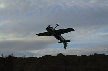
2 Dear Customer, Thanks for purchasing this newly designed MX2 50CC V2 aerobatic RC airplane. The weight is approximately 17Lbs. It s good for IMAC and free style flying. It s a beautiful plane with amazing flight performance. It s covered with genuine monocote, and comes with good quality accessories, including carbon fiber wing tube, Anodized 6061 aluminum landing gear or carbon fiber as an option. We hope you enjoy this plane. The new V2 version of MX2 has the following improvements from previous versions: 1.Control services is larger than V1 version. Up to 50 degrees of throw on all control surfaces. Best for more vibrant aerobatic flight. 2.Improved wheels with more durable materials, and filled with rubber. 3.Using high quality cap head screws. 4.Improved ball link assembly. 5. Improved new Axle.the material of Axle is stainless steel. 6. Improved new Dual Fiberglass horn assembly 7. Flat nylon hinges for better flying strength 8. Include Side Force Generator s(sfg) 9. Larger carbon fiber wing tube diameter than V1 Previous versions. 10. This V2 new design with a longer fuselage moment arm aids the tracking of the model, giving it rock sold precision flight. Making it perfect for modern day flight schedules for IMAC and Freestyle competitions. A QUICK WORD ABOUT SAFETY AND RADIO CONTROL FLYING MODELS With radio control aircraft, like any hobby or sport, there are certain risks. The operator of these models is responsible for these risks. If misused or abused, you may cause serious bodily injury and/or damage to property. With this in mind, you will want to be certain that you build your model carefully and correctly. If you are not an experienced flier, have your work checked and ask for help in learning to fly safely. This model aircraft is not a toy and must be operated and flown in a safe manner at all times. Always perform a pre-flight check of the model including all control surfaces, proper function of the radio gear, structure, radio range, and any other area relating to the safe operation of this aircraft. Models are not insurable but operators are. You can obtain coverage through membership in the Academy of Model Aeronautics (AMA). For an AMA information package call , ext. 292 or visit the AMA website at " By the act of using the final assembled model, the purchaser/operator accepts all resulting liability.

 GAS: 50CC-70CC Gas DLE55 DLE61 DA50 DA60 EME60 GP61 Electric Power: Hacker Q80-8M with 12S 5000mah 24x10 prop KUZA EXM 8015 with 12S 5000mah 24x10 prop Or other 4000Watt")
3 ARF MODELS WARRANTY AND RETURN POLICY We guarantee that the plane is in perfect condition at purchase. The warranty will be voided after modifications and usages. If you have any questions or find any issues, please contact the distributors in your area. SPECIFICATIONS WING SPAN:88-1/2" (2250mm) LENGTH: 85-3/4"(2180mm) WING AREA:1488sq in(96sq dm) FLYING WEIGHT: lbs( g) GAS: 50CC-70CC Gas DLE55 DLE61 DA50 DA60 EME60 GP61 Electric Power: Hacker Q80-8M with 12S 5000mah 24x10 prop KUZA EXM 8015 with 12S 5000mah 24x10 prop Or other 4000Watt electric motor ESC:160A RADIO:4+CH/5-6S FEATURES INCLUDED Newly designed structure Two pieces removable wings & stabs PVC canopy Larger aileron and elevator design for excellent 3D aerobatic flying Removable rudder

4 Includes Side Force Generator s(sfg) CNC anodized aluminum Canopy Bolts Full length Tuned pipe tunnel designed into fuselage

")

5 Anodized aluminum Long servo arms included Adjustable pushrods for easy fine tuning(includes wrench) Servo extension safety connector clips High performance cap head bolts


6 Flat nylon hinges for increased strength Honeycomb board carton packing for safer transportation High quality 3mm ball links assembly New dual fiberglass horn assembly


7 New Carbon fiber tail wheel assembly High-quality durable rubber wheels Improved new Axles (the material of the Axle is stainless steel )


8 Two options for landing gear: Anodized 6061 Aluminum or Carbon fiber Carbon fiber landing gear Increased diameter carbon fiber wing tube than previous V1 version. Carbon fiber stab tube


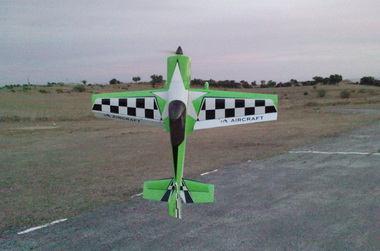
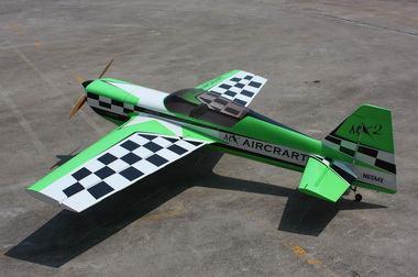
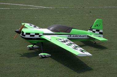
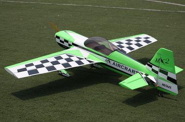
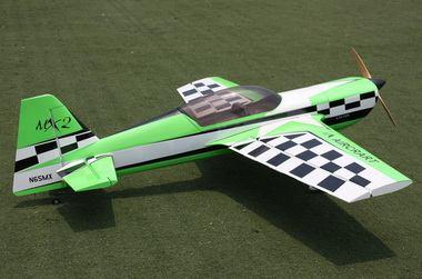
9 Scheme A White/black/green
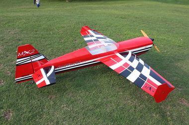
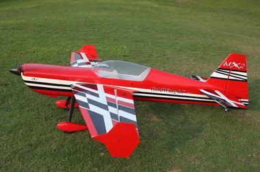
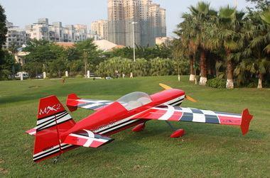
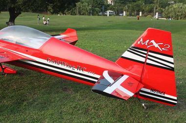
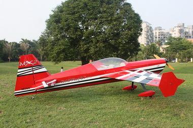
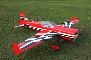
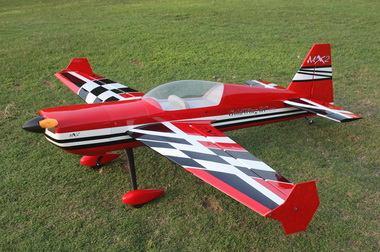
10 Scheme C Red/white/black


11 Items Required to Complete This Model: 50-70CC Gas engine and exhaust Appropriate propeller for your Motor All required engine and exhaust mounting hardware Ignition battery and switch One quality throttle servo and appropriate servo arm 4Pcs high quality metal gear servos or better for the ailerons and elevators Appropriate servo arms for the above Servo wire extensions. Recommends two 24, One 18, two 12 extensions Two switches with charging jacks for the Rx Two high quality Rx batteries of significant capacity to power your choice of servos. One Receiver of your choice Shop Supplies/Tools Covering Iron and heat gun Assortment normal hobby tools such as screwdrivers, hobby knife, drill and drill bits, pliers, etc. Thick and Thin CA adhesives 30 minute Epoxy Isopropyl alcohol Ruler or tape measure Blue thread-lock or equivalent Note: As with all kits, it s a good idea to read all the instructions and study the parts before you begin construction. Handle the parts of this kit with care so you do not damage any of the structure or covering. Inspect all the parts for any shipping damage and report any issues to as soon as you can. Make sure you have a flat and sturdy workbench and follow all safety advice for the tools and adhesives you plan to use. AIRCRAFT COVERING 1. With all ARFs, varying temperatures and storage delays can cause covering material to loosen over time and transportation. recommends lightly going over all the covering with a covering iron set at medium temperatures. Be sure to use a soft cover over your iron so you do not scratch the covering surface. Be sure you go over all seams and edges of the covering to assure it is secure to the airframe and other covering. Be careful not to apply too much heat or you may cause bubbles or damage to the covering. A heat gun may also be used along with a soft cotton cloth to shrink and adhere the covering. Again, be extremely careful when using a heat gun. 2. Be sure to seal any exposed wood with a thin coating of epoxy to prevent engine oil from soaking in. This is especially important around the engine compartment and servo openings with exposed areas.

: 8 single horns for ailerons and elevators. 2 dual horns for rudder.")
12 3. Some modelers prefer to seal the hinge gaps using strips of appropriate covering or clear trim tape. We have found this to be helpful with models intended for higher speed flight or models with unusually large hinge gaps. aircraft utilize a very tight double beveled hinge line and do not normally require this step. Sealing the hinge gaps is therefore left as an option for the modeler. Please locate the accessories before assembly: New Expoxy horn kits (Bag No. KA05CA): 8 single horns for ailerons and elevators. 2 dual horns for rudder. There is a layer of protection film on the horns. Please remove the film as shown following picture. Make sure to sand the horns so the surface is rough to glue correctly.
 Four 3x60mm pushrods for")


13 Pushrods(Bag No. KA05CBG3) Four 3x60mm pushrods for ailerons. One 3x165mm pushrods rudder (Pull-push style) Pull-pull assembly kits for the rudder. (Bag No. KA05CD) Ball link assemblies (Bag No. KAG00131): 8 for ailerons and elevators.
 Main rubber wheels (Bag No.")
14 Alu long arm kits (Bag No. KA05CC): 4 single arms for ailerons and elevators. 1 dual arm for the rudder. 6 Servo extension safety connector clips (Bag No. KAG0021) Main rubber wheels (Bag No. KAG014B):2PCS New stainless steel Axle kits (Bag No. KA05CH): 2PCS
 Side force generators (4 x 3x20mm hex bolts & 4 x washers & 2 balsa sheet) Bolts for landing gear: 4(4x20mm) Hexagon bolts & 4 washers&")
15 New Carbon fiber tail wheel assembly. (Bag No. KAG0104) Side force generators (4 x 3x20mm hex bolts & 4 x washers & 2 balsa sheet) Bolts for landing gear: 4(4x20mm) Hexagon bolts & 4 washers& 4mm stainless steel Self-locking nuts Bolts & washers for cowl: 4(3x16mm) Hexagon bolts & 4 washers

16 5 allen keys(bag No. KA05CE) Wing Assembly NOTE: There are pictures of different planes in this manual, however, this plane s wings is assembled the same way. 1.Aileron push rod linkage set. 3x60mm Pushrods for aileron. 2.It is much easier to install the twin control horns before installing the wing. Locate the fiberglass aileron control horns, ball links, and associated bolts and nylon-insert lock nuts. Use some fine sandpaper to roughen up the center areas of the two control horns so that the glue adheres better. Using a sharp hobby knife cut the covering away from the slots in the rudder and trial fit the two control horns. 3. Mix up some 30 minute epoxy and coat the inside of the slots and the center of the control horns. Hint: a scrap piece of 1/16 ply, tooth pick, or old hobby blade can be used to coat the inside of the aileron slots.


17 Slide the control horns in place and make sure they are centered perfectly by using a ruler to measure between the pivot holes and the hinge line. Wipe any excess glue off with isopropyl alcohol and paper towels. Install the ball links, bolts and nuts into the holes to help assure alignment of both control horns while the glue cures. Set aside until cured. 4. The slots for the supplied hinges are pre cut. Locate the hinges and dry fit the hinges and aileron into place and test the operation. The hinges should seat fully into the slots so that the hinge line gap is minimal while still allowing full aileron deflection. 5. Before gluing the hinges in you must first clean the hinges of any mold release agent using isopropyl alcohol. We also recommend scuffing up the plastic with light sandpaper for maximum glue adhesion. 6. Mix up some 30 minute epoxy and using a toothpick or small wooden dowel coat the inside of each hinge slot with epoxy. Also put a thin layer of epoxy on one side of the hinges. Install this end into the slots of the rudder and make sure each hinge is properly aligned at exactly 90 degrees to the hinge line. 7. Now coat the other end of the hinges with epoxy and install the aileron into the trailing edge of the wing. Again, make sure the hinges remain in proper alignment. Using paper towels and some isopropyl alcohol clean off any excess epoxy from the hinges and surrounding areas. 8. Make sure the aileron is fully seated so that the hinge gap is minimal while still allowing full deflection of the aileron. When satisfied, use some masking tape to hold the aileron in place along the bottom and counterbalance. After the epoxy has cured, remove the masking tape and check for proper operation. If the hinges are stiff some light oil carefully placed on each hinge will help greatly. 9. Cut the covering from the aileron servo openings from corner to corner and iron down inside the openings. Connect servo wire extensions to your servos and secure the connections with the supplied clips, your own clips, or tape. Feed the servo wires into the wing and out the root. Install the servos and screw firmly in place. 10. Use your radio to set the centers of each servo and then assemble and adjust the length of each control rod. The servo arm should be as close to perpendicular to the control rod as possible while the aileron is at


18 neutral. Double check all screws, bolts and nuts to assure proper installation and operation without binding.once satisfied, permanently attach the ball link to the servo arm with the supplied screw and nut. 11. Check the final radio operation of the ailerons and make sure there is no binding or servo fighting of each other. Also check to make sure all linkage bolts and nuts are secure. Use the wrench to adjust the pushrod to the appropriate length. Elevator Assembly NOTE: There are pictures of different planes in this manual, however, this plane s elevator is assembled the same way. 1. Push rod linkage set for elevator. 3x60mm Pushrods for elevator. 2. Find the slots for the control arms in the elevators and remove the covering where the horns are inserted and the area for the plate.


19 3. Sand the area on the horn that will be glued inside the elevator. 4. Using plenty of 30 minute epoxy fit the horn and plate into place. Use a ball joint and bolt to hold the horn in place while drying. REPEAT FOR THE OTHER SIDE 5. Place long arms onto the servo s you are planning to use for the elevators.


20 6. Place the servo into the elevator and screw in place. Remember to harden the holes with thin Cyano. 7. Place the servo arm back onto the servo, remembering to centre. Use nutlock on the servo arm screw. 8. Fit the pushrod in place remembering one end is reverse threaded. Set it so the arm is centered and the elevator is flat. Choose the holes depending on how much deflection you require.


21 Use the wrench to adjust the pushrod to the appropriate length. Rudder Assembly NOTE: There are pictures of different planes in this manual, however, this plane s rudder is assembled the same way. 1. Install the fiberglass control horns in the same way as you did the elevator horns.


22 2.The MX2 is supplied with a high quality set of pull-pull cables and ball-links. 3.Locate the pull-pull cable set, threaded couplers, brass swaging tubes, and ball-links. If the cable is one long piece, cut it into two equal length pieces. Thread one end of the one cable through a brass tube and then through one of the threaded couplers. Run the cable back through the brass tube and then loop it back through a second time. Using a set of crimping pliers, place three crimps just tight enough not to cut the brass tube but enough to securely hold the wire in place. Cut off the excess cable with wire cutters. Wick thin CA into the brass tube to help hold the cable secure. Repeat for the other cable. 4.Thread the couplers about half way into the ball links of the rudder. Hint: remove the ball links from the rudder horn first to make this step easier and then re-install once the couplers are threaded on. Feed the loose end of each cable into the cable slots at the rear of the fuselage and feed them forward towards the servo mount location. A coat hanger with a hook on the end can be useful here if you can t reach the cable. 5.Use your radio system to center the rudder servo and attach either the supplied arm or an appropriate arm for your servo. Thread one of the ball links about half way onto one of the threaded couplers. Feed the loose end of one of the cables through a brass tube and then through the threaded coupler. Holding the rudder centered, adjust the cable length as tight as possible while checking the ball link position over the servo arm. When satisfied with the position, pinch the cable around the threaded coupler and then feed the loose end back through the brass tube. Loop the cable back through the brass tube as before and crimp the brass tube three times just tight enough not to cut the brass tube but enough to securely hold the wire in place. Cut off the excess cable with wire cutters. Wick thin CA into the brass tube to help hold the cable secure. Repeat for the other cable. Hint: Once you have established the position of the threaded coupler on the cable, you can remove the ball link from the rudder horn to give you more working slack in the fuselage. Re-install the ball link prior to setting the other cable. 6. Check the operation of the rudder using your radio and make sure there is no binding and the cables are adjusted properly. You may have to tighten the cables after a few flights as they may stretch slightly from the initial installation.


23 7. The MX2 also provides pull-push style for rudder. Below is picture of pull-push style linkage set. Cut off excess fiberglass rudder horn, and use sandpaper to roughen up the parts needed to inlay. Use epoxy glue to glue the rudder horn.


24 Use 3x165mm push rod between the servo and the rudder horn. Then use the wrench to adjust the pushrod to the appropriate length. Tail Wheel Installation


25 1. Begin the tail wheel assembly by installing the hollow hex bolt and lock nut into the large hole at the rear of the tail wheel bracket. 2.Slide 3 wheel collars and the wheel onto the pre-bent tail wheel wire and tighten in place with thread lock as shown below. 3.Install steering rod, again, the use of thread-lock on any metal to metal screw is advised.


26 4.There are 3 pre-installed blind nuts on the rear of the fuselage, locate the screw holes and puncture the covering. Then install the CF tail wheel bracket with M3 hex bolts and washers. 5.Drill a screw hole on the bottom of rudder, mm away from the hinge line, with 2 mm drill bit. Secure one end of the wheel spring with a M3 12mm self-threaded screw, then hook the other end onto the steering rod.


27 6.Fully installed tail wheel assembly is shown below. Main Landing Gear Installation NOTE: There are pictures of different planes in this manual, however, this plane s landing gear is assembled the same way. 1. Locate the supplied main landing gear parts and sort them out on your workbench.


28 2. Bolt the main gear to the bottom of the fuselage using the supplied bolts. Place the nuts in through the can tunnel opening with appropriate size spanner. Remember the gear will rake forward. 3. Loosen out the second nut, then apply 30 minute epoxy glue on the axle. Tighten the nut back in place, allow at least 1 hours for threadlocker to dry.


29 4. Install the main wheel axles to the composite landing gear and tighten the nylon-insert lock nut. Install one wheel collar onto the axle. Use a second wheel collar as a guide to leave a gap on the inboard of the axle. Use a small drop of thread-lock and tighten in place. Slide the wheel onto the axle and install a second wheel collar also using thread-lock on the set screw. 5. Fit the wheel pant in place and install using the two supplied bolts. Use thread-lock to secure the bolts in place. Repeat the above steps for the other main gear. ENGINE, EXHAUST, & FUEL SYSTEM NOTE: There are pictures of different planes in this manual, however, this plane s engine is assembled the same way. 1.Templates are provided in the kit for both DA and 3W 50 cc engines as well as the DA 60 engine. Select the proper guide for your engine and mark and drill the mounting holes and cut out the center as indicated.


30 Notice that the engine center line is offset to the left to compensate for the right thrust built into the engine box. 2. Fit the Cowl and measure the distance from the engine bulkhead to the front of the cowl, add approx 2-3mm for the back plate and this is the length that your engine should be set Using the correct length stand offs, mount your engine securely using bolts, washers, and locknuts. The use of thread-lock is also highly essential for the engine bolts. 3. Mount the ignition module according to the manufacturer s instructions. The best place to mount it is on the side of the engine box. Secure the pickup lead and ignition wires with zip ties so that they do not vibrate or touch any hot part of the engine or exhaust. 4. Assemble the throttle servo mount using the supplied laser cut parts or there is a servo cutout in the bottom of the engine box for 50cc-70cc engines. Mount your throttle servo and complete your linkage setup. A hole will need to be drilled on the firewall to allow the pushrod to connect to the throttle arm on the carb.


31 5. An extra servo can be fitted for choke or a mechanical linkage can be used. 6. The fuel tank is preassembled. Complete the installation in the fuselage using zip ties or velcro straps to hold the tank in position. Connect a fuel line between the tank and carb, a fuel line between the tank vent and the bottom of the fuselage, and a fill line to a fueling port which can be mounted on the fuselage side opposite your ignition switch. Make sure your vent line does not come close to any hot exhaust part such as the muffler or canister. recommends the use of small zip ties or fuel line clamps to secure the lines to the tank.


32 A barb on the bottom of the fuselage can be fitted for the vent. 7. The MX2 comes with canister pipe tunnel. Standard muffler, pitts muffler, canister or tuned pipe can be fitted. If a tuned pipe is going to be used the end of the can tunnel can be removed. The tunnel can be closed off to accept canisters of all sizes, or stock mufflers. Follow the manufacturer s instructions for your exhaust system paying attention to vibration mounts if required and air flow requirements. Trial fit your exhaust system now and work out any additional supports, but do not permanently install the system until you fit the cowling in the next steps. Pitts Muffler Canister Fitting


33 Tuned Pipe Mounting The MX2 comes with many openings for the exhaust outlet, line up the exhaust then remove the covering for the required outlet. They come with covers that can be used for cooling. Use a soldering iron to open up the holes. COWLING INSTALLATION NOTE: There are pictures of different planes in this manual, however, this plane s colwing is assembled the same way. 1. With the engine fitted, tape a piece of card to the bottom of the fuselage that can overlap the cylinder head. Remove the engine and refit the cowl. Then fold over the card to show where the cylinder head would be as below.


34 2. Mark onto the cowel the area to remove, and remove with a dremel. As the MX2 has a scale inlet, depending on your engine it may need to be removed. If it is still attached it may be beneficial to strengthen with a small amount of glass cloth. If your exhaust outlet comes out within the cowl area then use the same method. Depending on the amount of cooling required for your engine a template for louvers in the bottom of the cowl has been provided. Use a dremel tool to remove the material. When the cowl clears the engine etc correctly the prop shaft of the engine will be in the centre of the cowl.


35 3.The cowl is secured with four 3 X 16mm bolts and washers. Apply nutlock onto the bolts as the vibration from the gas engine will shake them come loose.

36 FINAL RADIO SYSTEM INSTALLATION 1. Whether you 72 MHz systems or the newer 2.4 GHz systems, proper radio installation and care is vital to the safe and reliable operation of your aircraft. Follow the manufacturer s instruction for installation guidance of receivers and batteries paying attention to factors such as vibration isolation, adequate cooling, and clearances. 2. Mount your reciever(s) securely in a location which provides a clean and maintenance free solution to your setup. All servo wires should be neatly routed and secured in place so they will not come loose or flop around during flight. 3. The fuselage ply sides provide space to mount your switches just below the canopy. Mount your switches according to the manufacturer s instructions and route your wires safely and securely as above. 4. Your receiver battery(s) can be mounted in a variety of locations depending on your balance needs. Regardless of where you mount your batteries it is vital that they are very secure with no possibility of coming loose. Use double sided velcro to hold the batteries from sliding around and then use zip ties or velcro straps to secure them tightly in place. 5. Servo and battery leads are the life blood of your aircraft. Make sure all wires are top quality and connectors are tight and display no loose pins or frayed wires. Servo clips are provided in the kit for your convenience. These servo clips can even be glued to the wood structure using CA if desired. 6. Check all radio programming and control surface operations thouroughly before your initial flight. Check your radio range according to the radio manufacturer s instructions both with the engine off and running. BALANCING and PRE-FLIGHT 1. Most state of the art aerobatic aircraft allow for a wide margin for balancing depending on what level of precision or freestyle the pilot prefers. To perform properly without being too pitch sensitive, you must not go too aft on the CG. We recommends an initial CG setting of mm ( inches) behind the leading edge of the wing at the root. More experienced pilots may want to set the CG further aft for more 3D capability. Varying weights of engines and radio gear will dictate how you should install each. The batteries can easily be located pretty much anywhere in the fuselage. Note: The best way to check your balance is to trim for level flight at about 1/2 to 3/4 throttle and then roll inverted. The aircraft should maintain level flight with very little to no down elevator input. If the aircraft climbs when inverted then you ve probably got your CG too far aft. If the nose drops more than slightly, then you are most likely nose heavy.


37 Recommended control surface deflections: Low Rate High Rate Elevator 15 degrees degrees Rudder 25 degrees degrees Ailerons 25 degrees degrees Use exponential on the dual rates at levels that suit your flying style. If you find that you require tail weight and cannot move parts around the aircraft a rear hatch has been added. Glue in the inner ring, once the covering has been removed. FINAL ASSEMBLY AND PRE-FLIGHT INSPECTIONS 1. Before arriving at your flying field, be sure all your batteries are properly charged and all radio systems are in proper working order. 2. Installation of Rudder Rudder is removable for convenience in transportation, it is connected to fuselage by inserting a 1.8 mm steel rod through the hinge line.


38 Then install pull-pull ball links on control horns. 3.Installation of Elevators Connect extension servo wire, secure with safe clips. Attach elevators with 3X12mm Hex-head bolts and washers. 4.Install the wings onto the fuselage being careful to align the wing tube with the wings and not force it. The wing tube may be initially tight but will loosen some with use. Guide your servo wires into the fuselage openings and connect to the proper aileron channels. Servo clips are recommended. Once you have the wings fully seated in the fuselage tighten the wing bolts inside the fuselage.


39 5. Side force generators Assembly. Cut the wing film needed to be instal the SFG. Fixed the SFG Use M3X20 cap head bolts and washers and balsa sheet. 6. Fill your fuel tank making sure your vent line is not plugged or capped. With the canopy off, this is a good time to check for any fuel leaks. 7. Position the canopy in place and tighten the ALU Canopy Bolts. Be sure to use the supplied rubber washers under the screw heads.

40 8. If you have removed your horizontal stabilizers, install them once again and check all bolts and connections. 9. Check all control surfaces for secure hinges by performed a slight tug on the control surfaces and observing if there is any give in the hinges. Check all control rods, ball links, servo screws, etc. for proper operation and installation. 10. Check your batteries and perform a proper range check once again with the engine off and running. Be sure all surfaces are moving in the correct direction and the proper amount for your flying setup. Recommend Accessories(Not included): * KUZA Heavy duty 7075 aluminum Servo Arm For Futaba servo(25t): 47mm/1.75in Single No. KAG0S7F 100mm/4in Dual No. KAG0D723F For Hitec servo(24t): 47mm/1.75in Single No. KAG0S7H 100mm/4in Dual No. KAG0D73H
:")


41 For JR servo(23t): 47mm/1.75in Single No. KAG0S73J 100mm/4in Dual No. KAG0D73J * 3.5in C.F Spinner No. KAG0135 * Wingbags for 50CC No. KAG0094

42
Super Chipmunk 20-30CC Manual. Instruction Manual
 ARF MODEL Super Chipmunk 20-30CC Manual Instruction Manual Dear Customer, Thank you for purchasing this excellent almost-ready to fly R/C model. This plane is to be powered by 20-30CC gas engine. It can
74in SLICK540 30CC & 120E. Instruction Manual
 ARF MODEL 74in SLICK540 30CC & 120E Instruction Manual Dear Customer, Thanks for purchasing this newly designed SLICK540 120E and 30CC aerobatic RC airplane. The weight is approximately 10Lbs. It s good
GOLDWING RC 68in SLICK540 20CC & 90E Instruction Manual Two version to choice: 90 Electric or 20CC
 GOLDWING RC 68in SLICK540 20CC & 90E Instruction Manual Two version to choice: 90 Electric or 20CC Dear Customer, Thanks for purchasing this newly designed aerobatic RC airplane. Goldwing RC proudly presents
MX2 100CC & MXS-R 100CC Giant Scale Aerobatic Aircraft
 MX2 100CC & MXS-R 100CC Giant Scale Aerobatic Aircraft By the act of using the final assembled model, the purchaser/operator accepts all resulting liability. Included Features: Fuselage and Wing incorporate
Gasoline powered. Congratulations on your purchase of this excellent almost-ready-to-fly R/C
 Gasoline powered Congratulations on your purchase of this excellent almost-ready-to-fly R/C Congratulations on on your your purchase purchase of this of this excellent excellent almost-ready-to-fly almost-ready-to-fly
GoldWing RC. Pitts Python 50CC V4 Giant Scale Aerobatic Aircraft
 GoldWing RC Pitts Python 50CC V4 Giant Scale Aerobatic Aircraft Specifications Wing Span: 71"(1800mm) Length: 80"(2030mm) Wing Area: 1705sq in(110sq dm) Flying Weight: 16 17.6lbs(7300 8000g) Engine: 50CC
GoldWing RC. PIPER J3 50CC Giant Scale Aircraft
 GoldWing RC PIPER J3 50CC Giant Scale Aircraft Specifications Wing Span: 119"(3030mm) Length: 79-1/4"(2015mm) Wing Area: 2055sq in(132.6sq dm) Flying Weight: 18.7-22lbs(8.5-10kg) Gas: 50CC-70CC Gas DLE55,
GoldWing RC. 91in SLICK540 60CC Giant Scale Aerobatic Aircraft
 GoldWing RC 91in SLICK540 60CC Giant Scale Aerobatic Aircraft Specifications Wing Span: 91"(2310mm) Length: 90-1/2"(2290mm) Wing Area: 1513sq in(97.6sq dm) Flying Weight: 18-20lbs(8150-9100g) Gas: 50CC-70CC
GoldWing RC. 105in SLICK CC Giant Scale Aerobatic Aircraft
 GoldWing RC 105in SLICK540 100-120CC Giant Scale Aerobatic Aircraft Specifications Wing Span: 105"(2670mm) Length: 102"(2590mm) Wing Area: 2034sq in(131.2sq dm) Flying Weight: 27.5-29.5lbs(1.5-13.5kg)
GoldWing RC. Corvus Racer540 50CC V4 Giant Scale Aerobatic Aircraft
 GoldWing RC Corvus Racer540 50CC V4 Giant Scale Aerobatic Aircraft Dear Customer, Specifications Wing Span: 89-1/4"(2265mm) Length: 86-1/2"(2200mm) Wing Area: 1482sq in(95.6sq dm) Flying Weight: 16.5-17.8lbs(7500-8100g)
GOLDWING RC. YAK55M 30CC Giant Scale Aerobatic Aircraft
 GOLDWING RC YAK55M 30CC Giant Scale Aerobatic Aircraft Specifications Wing Span: 73"(1860mm) Length: 68"(1730mm) Wing Area: 1023sq in(66sq dm) Flying Weight: 9.7-11lbs(4400-5000g) Glow:.91-1.20(2C) 1.10-1.40(4C)
GOLDWING RC. 76in EDGE CC Giant Scale Aerobatic Aircraft
 GOLDWING RC 76in EDGE540 30-35CC Giant Scale Aerobatic Aircraft Specifications Wing Span: 76"(1930mm) Length: 74"(1880mm) Wing Area: 1063sq in(68.6sq dm) Flying Weight: 10-10.9lbs(4500-5400g) Gas: 26CC-38CC
GoldWing RC. 77in CORVUS 35CC & 170E Giant Scale Aerobatic Aircraft
 GoldWing RC 77in CORVUS 35CC & 170E Giant Scale Aerobatic Aircraft Specifications Wing Span: 77"(1960mm) Length: 74"(1890mm) Wing Area: 1190sq in(76.8sq dm) Flying Weight: 11.5-12.7lbs(5200-5700g) Gas:
Assembly Manual For. Wingspan: 88 in Wing area: sp in Length: 78.8 in Engine: 50CC.
 Assembly Manual For Wingspan: 88 in Wing area: 1479.8 sp in Length: 78.8 in Engine: 50CC www.pilot-rc.com INTRODUCTION Thank you for purchasing our new 50 cc model. We strive to bring you the most complete
EXTRA 330LX. Specifications: Code: SEA274. Graphics and specifications may change without notice. ASSEMBLY MANUAL
 ASSEMBLY MANUAL EXTRA 330LX Code: SEA274 Graphics and specifications may change without notice. Specifications: Wingspan---------------82.0 in (208.2 cm). Wing area---------------1349.4 sq.in ( 87.1 sq.dm).
96in Super Decathlon ARF
 96in Super Decathlon ARF Instruction Manual Specifications Wingspan: 96in (2438mm) Length: 63.5 in (1614mm) Weight: Approx. 13lbs (6.5kg) 1 Dear Customer, Congratulations on your purchase of Super Decathlon
51in Aerobatic Series Sukhoi SU-26M Almost-Ready-to-Fly. Instruction Manual. Specifications
 51in Aerobatic Series Sukhoi SU-26M Almost-Ready-to-Fly Instruction Manual Specifications Wingspan: 51.2 in (1300mm) Length: 51.2 in (1300mm) Wing Area: 581 sq in (37.5sq dm) Flying Weight: 3.5 lb (1600g)
Table of Contents. Tail Wheel Assembly Installation.. page 01. Stabilizer Installation.. page 02. Fin Installation.. page 03
 Table of Contents Tail Wheel Assembly Installation.. page 01 Stabilizer Installation.. page 02 Fin Installation.. page 03 Elevator and Rudder Hinge Installation.. page 04 Rudder Controls.. page 05 Elevator
Assembly Manual For. Wingspan: 88 in Wing area: sp in Length: 78.8 in Engine: 50CC.
 Assembly Manual For Wingspan: 88 in Wing area: 1479.8 sp in Length: 78.8 in Engine: 50CC www.pilot-rc.com INTRODUCTION Thank you for purchasing our new 50 cc model. We strive to bring you the most complete
MXS-EXP. 64 Inch Electric ARF Assembly Manual
 MXS-EXP 64 Inch Electric ARF Assembly Manual 1 Please take a few moments to read this instruction manual before beginning assembly. We have outlined a fast, clear and easy method to assemble this aircraft
MARACANA ASSEMBLY INSTRUCTION .40 ARF LOW WING TRAINER RADIO CONTROL MODEL. Every body can fly
 RADIO CONTROL MODEL ASSEMBLY INSTRUCTION MARACANA.40 ARF LOW WING TRAINER Every body can fly VQA085 EP GP You can use both Gas or Electric power Wingspan: 59in.(1520mm) Fuselage length: 48in.(1220mm) Engine:
RADIO CONTROL MODEL HURRICANE
 RADIO CONTROL MODEL VQAA040G VQAA040B HURRINE Almost ready to fly SPECIFITIONS Wingspan...63 in. / 161cm Length...50 in. / 129cm Engine...50~60 2T / 70~90 4T Or Electric equivalent. RC Functions: Motor
Aviator Pro 120 ARF. Instruction Manual. Specifications
 Aviator Pro 120 ARF Instruction Manual Specifications Wingspan: 110 in (2800 mm) Length: 74 in (1870 mm) Wing Area: 1581sq in (102 sq dm) Weight: 11.4-13.4 lbs (5190-6100 g) Dear Customer, Congratulations
RECOMMENDED MOTOR AND BATTERY SET UP
 SPECIFICATION - Wingspan: 6000mm (236.2 in) - Length: 2873mm (113.1 in) - Flying weight: 14-18 kg - Wing area: 219.4 dm2 - Wing loading: 64g/dm2 - Wing type: HQ airfoils - Covering type: Genuine ORACOVER
1 All our plane have the matching carbon fiber servo arms, carbon fiber main and tail landing gear, carbon fiber spinner and wood propeller available.
 Our airplane model: 1 All our plane have the matching carbon fiber servo arms, carbon fiber main and tail landing gear, carbon fiber spinner and wood propeller available. 2 Pre-glued cowling ring with
F3P Instruction Manual
 Before use, please read the explanations carefully! F3P Instruction Manual Specifications Fuselage length: 884mm ( 34. Bin ) Wingspan : 845mm ( 33. 2in) Flying Weight : 135-160g (with battery) Additional
Turbinator-2 Build Manual
 Turbinator-2 Build Manual Thank you for your purchase of the Turbinator-2 sport jet by Boomerang RC Jets. This RC Jet IS NOT A TOY and should only be flown and operated by experienced RC Turbine Pilots.
STICK F Class 60 Class INSTRUCTION MANUAL. Or Electric equivalent. (2T engine) (4T engine) Radio control model SPECIFICATIONS
 (4T engine) Radio control model SPECIFICATIONS") Radio control model 45 Class 60 Class (2T engine) (4T engine) Or Electric equivalent INSTRUCTION MANUAL STICK F - 1500 SPECIFICATIONS Wingspan 60 in. Length 38.5 in. Electric Motor 650 Watt Glow Engine.45
Radio control model 45 Class 60 Class (2T engine) (4T engine) Or Electric equivalent INSTRUCTION MANUAL STICK F - 1500 SPECIFICATIONS Wingspan 60 in. Length 38.5 in. Electric Motor 650 Watt Glow Engine.45
YAK-54 EXP. 48 inch Electric ARF
 YAK-54 EXP 48 inch Electric ARF 1 Greetings and congratulations on your purchase of the Extreme Flight RC Yak-54 EXP ARF! Like all of the EXP series, the YAK-54 excels at both 3D and precision maneuvers.
Radio control model INSTRUCTION MANUAL PYLON RACING. Wingspan: 1148mm (45.2 ) Radio : 4 channels Engine : two-stroke
 Radio : 4 channels Engine : two-stroke") VQA038 VQA039 Radio control model INSTRUCTION MANUAL MAGIC PYLON RACING Wingspan: 1148mm (45.2 ) Radio : 4 channels Engine :.25 -.32 two-stroke WARNING! This radio control model is not a toy. If modified
VQA038 VQA039 Radio control model INSTRUCTION MANUAL MAGIC PYLON RACING Wingspan: 1148mm (45.2 ) Radio : 4 channels Engine :.25 -.32 two-stroke WARNING! This radio control model is not a toy. If modified
RADIO CONTROL MODEL ASSEMBLY INSTRUCTIONS. Wasp
 RADIO CONTROL MODEL ASSEMBLY INSTRUCTIONS Wasp TRAINER Almost ready-to-fly Wingspan 1520mm Fuselage length 1105mm Engine: 40-46 2T / 52-60 4T Electric Motor: 600-700W Radio: 5 channel / 4-5 servo RC Functions:
Gent EPP. Before use please read the explanations carefully
 Before use please read the explanations carefully Gent EPP Instruction Manual Specifications Fuselage length 900mm 35in Wingspan 820mm 32in Flying Weight 210 240g with battery Additional Required Equipment
Instruction Manual. Item No: AL506
 Instruction Manual Item No: AL506 Specifications: Wingspan: 2218mm (87.3 in) Length: 1892mm (74.5 in) Wing Area: 100dm2 (1550 sq in) Flying Weight: 7.3kg (16.1 lbs) Engine(not incl.): 50-60cc Gas Radio(not
Instruction Manual. Wingspan : 2270mm (89.37 inches) : 1870mm (73.62 inches) : 7400gr gr. : 4 channel - 6 standard servo.
 : 1870mm (73.62 inches) : 7400gr gr. : 4 channel - 6 standard servo.") Wingspan : 2270mm (89.37 inches) g Length : 1870mm (73.62 inches) Weight : 7400gr - 7600gr Radio : 4 channel - 6 standard servo Engine : 25cc-35cc KIT CONTENTS: We have organized the parts as they come
Wingspan : 2270mm (89.37 inches) g Length : 1870mm (73.62 inches) Weight : 7400gr - 7600gr Radio : 4 channel - 6 standard servo Engine : 25cc-35cc KIT CONTENTS: We have organized the parts as they come
AVIATOR 25 ARF Almost Ready-to-Fly
 AVIATOR 25 ARF Almost Ready-to-Fly Instruction Manual Specifications Wingspan: 54.3 in (1380mm) Length: 45.2 in (1150mm) Wing Area: 438 sq in (34sq dm) Flying Weight: 3.8 b (1700g) Dear Customer, Congratulations
SBACH SCALE 1:4 ½ ARF
 SPECIFICATION - Wingspan: 1663mm (65.5 in) - Length: 1638mm (64.5 in) - Flying weight: 4700-5200 gr - Wing area: 56 dm2 - Wing loading: 85g/dm2 - Wing type: Naca airfoils - Covering type: Genuine ORACOVER
RECOMMENDED MOTOR AND BATTERY SET UP
 SPECIFICATION - Wingspan: 2000mm (78.7in) - Length: 1544mm (60.7 in) - Flying weight: 3600-3800 gr - Wing area: 66 dm2 - Wing loading: 55g/dm2 - Wing type: Naca airfoils - Covering type: Genuine ORACOVER
RECOMMENDED MOTOR AND BATTERY SET UP
 SPECIFICATION - Wingspan: 1404mm (55.3in) - Length: 1134mm (44. 6 in) - Flying weight: 3.2-3.4 kg - Covering type: Genuine ORACOVER - Spinner size: scale type (not included) - Radio: 4 channel minimum
ALMOST READY TO FLY. Wing Span in cm. 2
 ASSEMBLY MANUAL ALMOST READY TO FLY MS:X9 Specifications Wing Span --------------------------61.4 in ---------------------------156cm. 2 Wing Area --------------------------606.1 sq.in ------------------
Lanier R/C F-4 Phantom
 Lanier R/C.40-.46 F-4 Phantom Almost Ready to Fly WARNING! THIS IS NOT A TOY! THIS IS NOT A BEGINNERS AIRPLANE This R/C kit and the model you will build from it is not a toy! It is capable of serious bodily
Instruction Manual. Wingspan : 1400 mm (55.12 inch) : 1480 mm (58.27 inch) : 5500gr gr. : 6-9 channel/ 8 servo high torque,1 standard
 : 1480 mm (58.27 inch) : 5500gr gr. : 6-9 channel/ 8 servo high torque,1 standard") Wingspan : 1400 mm (55.12 inch) g Length : 1480 mm (58.27 inch) Weight : 5500gr - 6000gr Radio : 6-9 channel/ 8 servo high torque,1 standard Engine : GT 22 OS KIT CONTENTS: We have organized the parts
Wingspan : 1400 mm (55.12 inch) g Length : 1480 mm (58.27 inch) Weight : 5500gr - 6000gr Radio : 6-9 channel/ 8 servo high torque,1 standard Engine : GT 22 OS KIT CONTENTS: We have organized the parts
ALMOST READY TO FLY. Wing Span in cm. 2
 ASSEMBLY MANUAL ALMOST READY TO FLY MS: X12 A - B Graphics and specfications may change without notice. Kit features. Specifications Wing Span ------------------------------- 42.7 in ---------------------
93 AJ Laser 230z Assembly Instructions
 93 AJ Laser 230z Assembly Instructions Congratulations AJ Aircraft thanks you for the purchase of this airplane. Top grade materials and precision assembly has gone into this to make this a top quality
I n s t r u c t i o n M a n u a l. Instruction Manual SPECIFICATION
 I n s t r u c t i o n M a n u a l Instruction Manual SPECIFICATION - Wingspan: 3200mm (125,9 in) - Length: 1650mm (64,9 in) - Flying weight: 3000gr 3200gr - Wing area: 64.5 dm2 - Wing loading: 46g/dm2
YAK54 MK2. GP/EP size.120/20cc SCALE 1:4 ¾ ARF. Instruction Manual. version. version
 Instruction Manual GP EP version version GP/EP size.10/0cc SCALE 1:4 ¾ ARF SPECIFICATION - Wingspan: 168 (66.3 in) - Length: 1605mm (63.1 in) - Flying weight: 4700-500 gr - Wing area: 54.7 dm - Wing loading:
PilotRC EDGE USER MANUAL. WINGSPAN:1710mm LENGTH:1554mm
 PilotRC EDGE540 67 USER MANUAL WINGSPAN:1710mm LENGTH:1554mm Introduction Thank you for purchasing our Edge 540 plane. we strive to achieve a good quality quick build ARF aircraft. It requires the least
: 6 channel - 9 servo
 g Wingspan : 2005mm (78.94 inches) Length : 1640mm (64.57 inches) Weight : 6400g - 6600g Engine : 25cc - 35cc Radio : 6 channel - 9 servo KIT CONTENTS: We have organized the parts as they come out of
SIZE.120 OR 30CC SCALE 1:5 ARF
 PC21 PILATUS MK2 SIZE.120 OR 30CC SCALE 1:5 ARF SPECIFICATION - Wingspan: 1772mm (69.72in) - Length: 2019mm (79.5 in) - Flying weight: 6.4-7.2 kg - Wing area: 57.6 dm2 - Wing loading: 113g/dm2 - Wing type:
Pitts Challenger m (100cc) MANUAL
 MANUAL") Pitts Challenger 87 2.20m (100cc) MANUAL 1- Introduction: WELCOME TO THE PILOT-RC TEAM! Thank you for choosing a Pilot-Rc plane as your next model. We hope that you enjoy many successful and exhilarating
Pitts Challenger 87 2.20m (100cc) MANUAL 1- Introduction: WELCOME TO THE PILOT-RC TEAM! Thank you for choosing a Pilot-Rc plane as your next model. We hope that you enjoy many successful and exhilarating
PANTERA Electric Prop Jet ARF
 PANTERA Electric Prop Jet ARF Copyright 2017 Extreme Flight 1 Greetings and congratulations on your purchase of the SPEED FREAK PANTERA! The PANTERA is the second release from SPEED FREAK and is built
29% KATANA ARF ASSEMBLY MANUAL
 29% KATANA ARF ASSEMBLY MANUAL Required but not included Aircraft Specifications: 4 channel radio and supporting equipment Wing Span 84 Engine 3.2-4.2 c.i. (50-60 c.c.) Wing Area 1270 Sq. in. Fuel Tank
RECOMMENDED MOTOR AND BATTERY SET UP
 SPECIFICATION - Wingspan: 2190mm (86.2 in) - Length: 1907mm (75 in) - Flying weight: 9000-12000 gr - Wing area: 92 dm2 - Wing loading: 98g/dm2 - Wing type: Naca airfoils - Retract gear type: Air-retract
1660mm (65.4 in) 1200mm (47.2 in) 2700gr gr 6 channel - 7 servo standard 46/ 2 stroke or 52/ 4 stroke
 1200mm (47.2 in) 2700gr gr 6 channel - 7 servo standard 46/ 2 stroke or 52/ 4 stroke") Instruction Manual CESSNA-46 1660mm (65.4 in) 1200mm (47.2 in) 2700gr - 3000gr 6 channel - 7 servo standard 46/ 2 stroke or 52/ 4 stroke KIT CONTENTS: We have organized the parts as they come out of the
Instruction Manual CESSNA-46 1660mm (65.4 in) 1200mm (47.2 in) 2700gr - 3000gr 6 channel - 7 servo standard 46/ 2 stroke or 52/ 4 stroke KIT CONTENTS: We have organized the parts as they come out of the
I/C FLIGHT GUIDELINES
 SPECIFICATION - Wingspan: 3500mm (137.8 in) - Length: 1650mm (64.96 in) - Flying weight: 3700-4000 gr - Wing area: 75 dm2 - Wing loading: 49g/dm2 - Wing type: HQ profile - Covering type: Genuine ORACOVER
: 7 channel - 9 servo, Hi-Torque ( Minimum 6 kg ).
.") g Wingspan : 1820mm (71.65 inches) Length : 1625mm (63.98 inches) Weight : 6900gr Engine : 25cc - 35cc Radio : 7 channel - 9 servo, Hi-Torque ( Minimum 6 kg ). KIT CONTENTS: We have organized the parts
g Wingspan : 1820mm (71.65 inches) Length : 1625mm (63.98 inches) Weight : 6900gr Engine : 25cc - 35cc Radio : 7 channel - 9 servo, Hi-Torque ( Minimum 6 kg ). KIT CONTENTS: We have organized the parts
Decathlon 107 USER MANUAL. WINGSPAN: 2700mm LENGTH: 1890mm
 Decathlon 107 USER MANUAL WINGSPAN: 2700mm LENGTH: 1890mm Introduction Thank you for purchasing our Deacthlon plane. we strive to achieve a good quality quick build ARF aircraft. It requires the least
MS:176 ASSEMBLY MANUAL. Graphics and specifications may change without notice.
 ASSEMBLY MANUAL MS:176 Graphics and specifications may change without notice. Specifications: Wing span ------------------------------98.4in (250cm). Wing area ----------------1576.4sq.in (101.7sq dm).
Instruction Manual book
 book SPECIFICATION Wingspan : 1,450 mm 57.09 in. Length : 1,200mm 47.24in. Weight : 3.1 kg 6.82 Lbs. Radio : 05 channels. Servo : 07 servos. Engine : 61-75 2 stroke. 91 4 stroke. Made in Vietnam. This
48in Sbach-342. Instruction Manual. Specifications
 48in Sbach-342 Instruction Manual Specifications Wingspan: 48in (1219mm) Length: 46in (1163mm) Wing Area: 471sq in (30.4sq dm) Flying Weight: 1.8-2.0lb (800-900g) Dear Customer, www.valuehobby.com/48in-s342-arf.html
ASSEMBLY MANUAL. Graphics and specifications may change without notice.
 NEMESISMS: SEA 111 ASSEMBLY MANUAL Graphics and specifications may change without notice. Specifications Wing span------------------------------------- 55.9in ------------------------------- 142cm. Wing
RECOMMENDED MOTOR AND BATTERY SET UP
 SPECIFICATION - Wingspan: 1410mm (55.5 in) - Length: 1278mm (50.3 in) - Flying weight: 3.2-3.4 kg - Wing area: 41.3 dm2 - Wing loading: 75g/dm2 - Wing type: Naca airfoils - Covering type: Genuine ORACOVER
RECOMMENDED MOTOR AND BATTERY SET UP
 SPECIFICATION - Wingspan: 1800mm (70.8 in) - Length: 1355mm (53.3 in) - Flying weight: 4100-4300 g - Wing area: 51 dm2 - Wing loading: 80g/dm2 - Wing type: Naca airfoils - Covering type: Genuine ORACOVER
MONOCULP/SR 9 MANUAL BR COLOR BY COLOR BW COLOR RW COLOR
 MONOCULP/SR 9 MANUAL BR COLOR BY COLOR BW COLOR RW COLOR Caution! You should not regard this plane as a toy! To ensure safety, please read this instruction manual thoroughly before assembly. Building
Slick Assembly Manual
 Slick Assembly Manual Slick Assembly Manual Thank you for purchasing the RedWing RC Slick. We have provided you with the highest quality kit and flight performance possible. We wish you great success in
Instruction Manual. Specification:
 Instruction Manual L O W Specification: Wingspan: 133 cm (52.3 inches) Length : 104 cm (40.9 inches) Weight : 1790gr Engine : 25-32 two stroke Radio : 4 channel - 4 servo W I N G KIT CONTENTS: We have
to fly. Most hardware included and all replacement parts are available.
 Instruction Manual The Thunderbolt P47 was perhaps the greatest of world war II in terms of all round performance and capability Phoenix Model has recreated a 2C - 60 class engine (or 4c 91 class) It was
8mm EPP Acrocub. Instruction Manual. Specifications
 8mm EPP Acrocub Instruction Manual Specifications Wingspan: 34.6 in (880mm) Length: 31.5 in (800mm) Wing Area: 213.9 sq in (13.8sq dm) Flying Weight: Approx. 9oz (270g) Dear Customer, www.valuehobby.com/8mm-epp-acrocub.html
ASSEMBLY MANUAL. Kit features. MS:76
 ASSEMBLY MANUAL MS:76 Graphics and specfications may change without notice. Specifications: Wingspan---------------------------------------------------- 82.8 in------------------------------------- 210.3cm.
Instruction Manual. Wingspan : 1400mm (55.12 in) : 1370mm (53.94 in) : 2600gr gr. : 4 channel / 5 servo. : / 2 stroke_52-71 / 4 stroke
 : 1370mm (53.94 in) : 2600gr gr. : 4 channel / 5 servo. : / 2 stroke_52-71 / 4 stroke") Instruction Manual 540 Wingspan : 1400mm (55.12 in) g Length : 1370mm (53.94 in) Weight : 2600gr - 2800gr Radio : 4 channel / 5 servo Engine : 46-52 / 2 stroke_52-71 / 4 stroke KIT CONTENTS: We have organized
Instruction Manual 540 Wingspan : 1400mm (55.12 in) g Length : 1370mm (53.94 in) Weight : 2600gr - 2800gr Radio : 4 channel / 5 servo Engine : 46-52 / 2 stroke_52-71 / 4 stroke KIT CONTENTS: We have organized
Trainer Assembly Manual
 Trainer Assembly Manual www.pilot-rc.com -Pilot Trainer- 1 -Pilot Trainer- 2 -Pilot Trainer- 3 -Preliminary i wing & stab assembly- 1-) Locate both Plywood wing joiners (Large and small one) 2-) Insert
MS:136 ASSEMBLY MANUAL. Graphics and specifications may change without notice.
 ASSEMBLY MANUAL MS:136 Graphics and specifications may change without notice. Specifications: Wing span ----------------------------79.5in (202cm). Wing area -----------------965.7sq.in (62.3sq dm). Weight
Wilga 20cc. Assembly Manual
 Wilga 20cc Assembly Manual Caution! You should not regard this plane as a toy! To ensure safety, please read this instruction manual thoroughly before assembly. Building and operating a model plane requires
MS:183 ASSEMBLY MANUAL. Graphics and specifications may change without notice.
 MS:183 ASSEMBLY MANUAL Graphics and specifications may change without notice. Specifications: Wing span ------------------------------79.9in (203cm). Wing area -----------------1165.6sq.in (75.2sq dm).
CAP 232 ASSEMBLY MANUAL
 CAP 232 MS: ASSEMBLY MANUAL SEA 91 Graphics and specfications may change without notice. Specifications Wingspan------------------------------------ 65 in --------------------------------- 165cm. Wing
RECOMMENDED MOTOR AND BATTERY SET UP
 SPECIFICATION - Wingspan: 2567mm (101in) - Length: 2190mm (86.2 in) - Flying weight: 11-13 kg - Wing area: 101 dm2 - Wing loading: 99g/dm2 - Wing type: Naca airfoils - Covering type: Genuine ORACOVER -
MS:159 ASSEMBLY MANUAL. Graphics and specifications may change without notice.
 ASSEMBLY MANUAL MS:159 Graphics and specifications may change without notice. Specifications: Wing span ----------------------------61.8in (157cm). Wing area -----------------1100.5sq.in (71.0sq dm). Weight
INSTRUCTION MANUAL BOOK
 INSTRUCTION MANUAL BOOK ITEM CODE BH57. SPECIFICATION Wingspan: 1,470 mm. 57.87 in. Length : 1,180 mm. 46.46 in. Weight : 2.7 Kg. 5.94 Lbs. Engine : 46 cu.in 2 stroke. 52 cu.in 4 stroke. Radio : 4 channels.
the leading edge of the wing, at the fuselage - Length: 1540mm (60.6 in) 10% expo; High: 15mm up/down, 10% expo - Wing area: 40dm2
 10% expo; High: 15mm up/down, 10% expo - Wing area: 40dm2") SPECIFICATION - Gravity CG: 165-170 mm (6.5-6.7 in) Back from - Wingspan: 1400mm (55.1 in) the leading edge of the wing, at the fuselage - Length: 1540mm (60.6 in) - Control throw Ailerons: Low: 12mm up/down,
SPECIFICATION - Gravity CG: 165-170 mm (6.5-6.7 in) Back from - Wingspan: 1400mm (55.1 in) the leading edge of the wing, at the fuselage - Length: 1540mm (60.6 in) - Control throw Ailerons: Low: 12mm up/down,
PilotRC Trainer USER MANUAL
 PilotRC Trainer USER MANUAL Introduction Thank you for purchasing our Trainer plane. we strive to achieve a good quality quick build ARF aircraft. It requires the least amount of assembly of any ARF kit
Instruction Manual book
 Instruction Manual book ITEM CODE:BH118. SPECIFICATION Wingspan : 1,050 mm 41.34 inches. Length : 950mm 37.4 inches. Weight : 1 kg 2.2 lbs. Radio : 04 channels. Servo : 4 mini servos. Motor : BL2215/20
 WWW.SEAGULLMODELS.COM ASSEMBLY MANUAL Graphics and specifications may change without notice. Code: SEA231 Specifications: Wingspan---------------80 in (203.2 cm). Wing area---------------1235.4 sq.in (79.7
Instruction Manual book
 Instruction Manual book SPECIFICATION Wingspan : 1,800mm. 70.87 in. Length : 1,350 mm. 53.15in. Weight : 3.6kg. 7.92lbs. Parts Listing required (not included). Glow Engine : 55-61 2 stroke. 91 4 stroke.
Instruction Manual book
 Instruction Manual book ITEM CODE:BH118. SPECIFICATION Wingspan : 1,050 mm 41.34 inches. Length : 950mm 37.4 inches. Weight : 1 kg 2.2 lbs. Radio : 04 channels. Servo : 4 mini servos. Motor : KMS 2814/05
ARF TRAINER KIT ASSEMBLY MANUAL BOOMERANG EP. ALMOST READY TO FLY
 WWW.SEAGULLMODELS.COM ASSEMBLY MANUAL BOOMERANG EP ARF TRAINER KIT Graphics and specifications may change without notice. MS: 211 ALMOST READY TO FLY Specifications: Wingspan---------------56.0 in (142.2
LASER 200. Hand-made Almost Ready to Fly R/C Model Aircraft ASSEMBLY MANUAL
 LASER 200 Hand-made Almost Ready to Fly R/C Model Aircraft ASSEMBLY MANUAL SPECIFICATIONS: WING SPAN ----------------------------------------175CM -------------------------------- 68.75 in. WING AREA ------------------------------------------4746CM2
PITTS 12 R/C SPORT-SCALE AIRCRAFT ASSEMBLY AND INSTRUCTION MANUAL. Copyright Century UK Limited 2012
 PITTS 12 R/C SPORT-SCALE AIRCRAFT ASSEMBLY AND INSTRUCTION MANUAL 1 Warning: This radio controlled model is not a toy. It requires skill to fly and is not recommended for use by beginners. It should not
Instruction Manual book
 book Item code:bh131 SPECIFICATION Wingspan : 3,000 mm 118.1 in. Length : 1,600 mm 62.99 in. Weight : 2.2 kg 4.84 Lbs. Radio : 05 channels. Servo : 06 mini servos. Electric Motor: BOOST 40 Battery : 3celIs
Instruction Manual book
 book SPECIFICATION Wingspan : 2,080 mm 81.89 in. Length : 1,680 mm 66.14 in. Weight : 6.2 kg 13.64 Lbs. Radio : 06 channels. Servo : 06 servos. Engine : 30-35 CC Gas(FUJI IMVAC). Made in Vietnam. This
ASSEMBLY MANUAL
 www.seagullmodels.com MS: X104 ASSEMBLY MANUAL Graphics and specifications may change without notice. Specifications: Wing span ----------------- 35.4in (90.0cm). Wing area ------------------392.2sq.in
 WWW.SEAGULLMODELS.COM ASSEMBLY MANUAL Code: SEA238 Graphics and specifications may change without notice. Specifications: Wingspan---------------68.9 in (175 cm). Wing area---------------776.6 sq.in (
JUNKERS CL1 G-BUYU. Specifications: Code: SEA275. Graphics and specifications may change without notice. ASSEMBLY MANUAL
 ASSEMBLY MANUAL JUNKERS CL1 G-BUYU Code: SEA275 Graphics and specifications may change without notice. Specifications: Wingspan---------------68.9 in (175 cm). Wing area---------------776.6 sq.in ( 50.1
YAK-55M 1.8. Forget the rest - a YAK ist the best! Assembly instructions. Gernot
 YAK-55M 1.8 Assembly instructions Forget the rest - a YAK ist the best! Gernot Table of contents 1.Specifications (metric units)...2 2.Recommended Setups...2 3.Required tools and adhesives:...2 4.Warning...3
94 Edge 540 ARF WARNING. Lanier R/C, INC. P.O. Box 458 Oakwood, Ga PH copyright 2006 Lanier R/C
 94 Edge 540 ARF WARNING A radio-controlled model is not a toy and is not intended for persons under 16 years old. Keep this kit out of the reach of younger children, as it contains parts that could be
ARF. Specifications: ASSEMBLY MANUAL MS: 193. Graphics and specifications may change without notice.
 ASSEMBLY MANUAL Graphics and specifications may change without notice. MS: 193 ARF Specifications: Wingspan---------------62.0 in (157.5 cm). Wing area----------------620 sq.in (40.0 sq.dm). Weight-------------------3.3-3.9
RECOMMENDED EDF AND BATTERY SET UP
 SPECIFICATION - Wingspan: 1150mm (45.3 in) - Length: 1587mm (62.5 in) - Flying weight: 5.0-5.3 kg - Wing area: 40dm2 - Wing loading: 125g/dm2 - Wing type: Naca airfoils - Covering type: Genuine ORACOVER
ASSEMBLY MANUAL. Specifications
 ASSEMBLY MANUAL MS: SEA 82 Graphics and specfications may change without notice. Specifications Wingspan-------------------------------------- 70.9 in------------------------------ 180cm. Wing area-------------------------------------
35cc EXTRA 260 ARF-QB (Quick Build)
") 35cc EXTRA 260 ARF-QB (Quick Build) ASSEMBLY MANUAL AEROWORKS 401 Laredo Unit D, Aurora, CO. 80011 - Phone 303-366-4205 - Fax 303-366-4203 E-mail - info@aero-works.net 1 TABLE OF CONTENTS Page Aeroworks
35cc EXTRA 260 ARF-QB (Quick Build) ASSEMBLY MANUAL AEROWORKS 401 Laredo Unit D, Aurora, CO. 80011 - Phone 303-366-4205 - Fax 303-366-4203 E-mail - info@aero-works.net 1 TABLE OF CONTENTS Page Aeroworks
RECOMMENDED MOTOR AND BATTERY SET UP
 SPECIFICATION - Wingspan: 1669mm (65.7in) - Length: 1229mm (48.43 in) - Flying weight: 3300-3400 gr - Wing area: 44.2 dm2 - Wing loading: 67g/dm2 - Wing type: Naca airfoils - Covering type: Genuine ORACOVER
HERO 3D SCALE 1:6 ARF
 Instruction Manual SPECIFICATION - Wingspan: 1500mm(59 in) - Length: 1410mm (55.5 in) - Flying weight: 2100-2300 gr - Wing area: 58 dm2 - Wing loading: 39g/dm2 - Covering type: Genuine ORACOVER - Gear
SU-31 PROFILE ELECTRIC ARF ASSEMBLY MANUAL
 SU-31 PROFILE ELECTRIC ARF ASSEMBLY MANUAL 1 TABLE OF CONTENTS Page Aeroworks Contact Information... 3 Introduction.. 4 Kit Contents... 5 Items needed to complete 6 Wing Assembly. 7 Stab Assembly. 10 Flight