T=PAER. T- cuplul de fr$nare; P-presiunea A-suprafa]a de aplicare; E-coeficientul de fr$nare; R-raza discului.
|
|
|
- Gilbert Berry
- 6 years ago
- Views:
Transcription
1 SISTEMUL DE FR#NARE
![T=PAER T- cuplul de fr$nare; P-presiunea aplicat@; A-suprafa]a de](/docs-images/78/77610171/images/2-0.jpg "aplicare; E-coeficientul de fr$nare; R-raza discului.")
2 T=PAER T- cuplul de fr$nare; P-presiunea A-suprafa]a de aplicare; E-coeficientul de fr$nare; R-raza discului. Fr$na cu disc

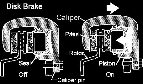
3 Fr$na cu disc

4 Fr$na cu disc

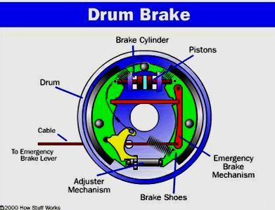
5 Fr$na cu tambur T=PAER T- cuplul de fr$nare; P-presiunea A-suprafa]a de aplicare; E-coeficientul de fr$nare; R-raza discului.
6

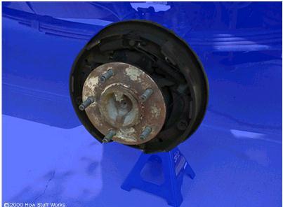
7 Fr$na cu tambur

8 Fr$na cu tambur
![P= (F in G mec G b -F spr )/A piston P-presiunea ^n cilindru; F in -for]a de ac]ionare a pedalei; G mec -amplificarea mecanic@ a](/docs-images/78/77610171/images/9-0.jpg "pedalei; G b -amplificarea boosterului; F spr -reac]iunea arcului pedalei; A-suprafa]a pistonului. Elementele de comand@ G mec =3.")
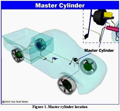
9 P= (F in G mec G b -F spr )/A piston P-presiunea ^n cilindru; F in -for]a de ac]ionare a pedalei; G mec -amplificarea mecanic@ a pedalei; G b -amplificarea boosterului; F spr -reac]iunea arcului pedalei; A-suprafa]a pistonului. Elementele de comand@ G mec =3...4; G b =5...9
10

11 Elementele de
12
13
14
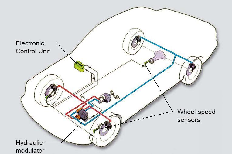
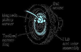
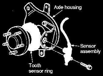
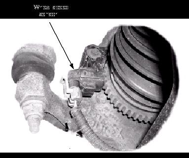
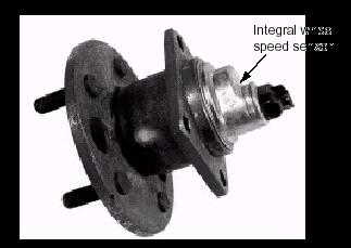
15 The anti-lock brake system () consists of the following components: Hydraulic Control Unit (HCU). Anti-lock brake control module. Front anti-lock brake sensors / rear anti-lock brake sensors.
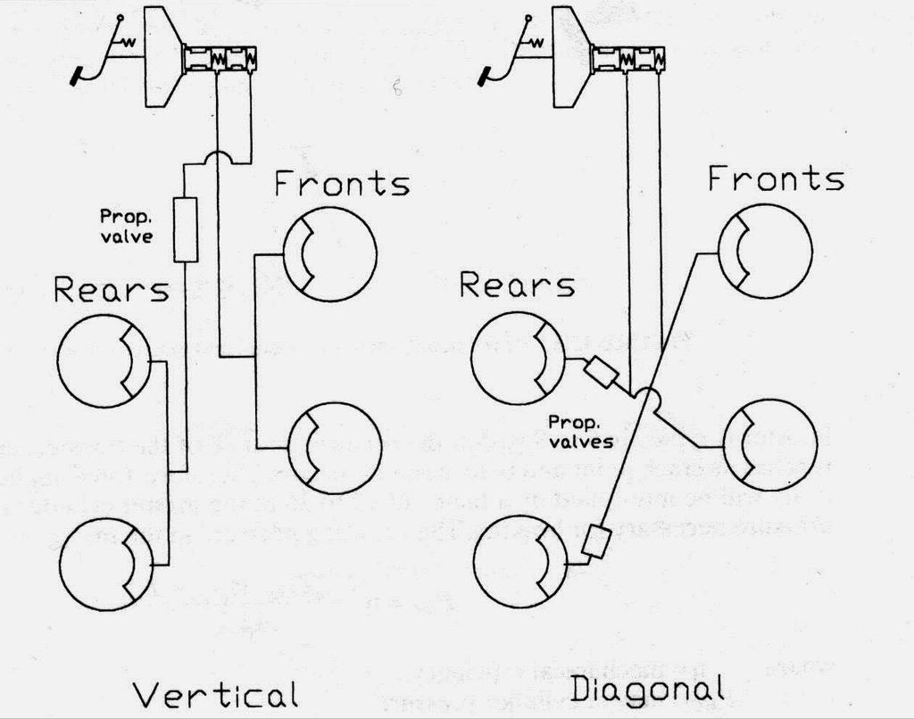
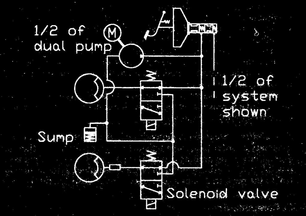
16 Anti-lock Brake System () operates as follows: - When the brakes are applied, fluid is forced from the brake master cylinder outlet ports to the HCU inlet ports. This pressure is transmitted through four normally open solenoid valves contained inside the HCU, then through the outlet ports of the HCU to each wheel. - The primary (rear) circuit of the brake master cylinder feeds the front brakes. - The secondary (front) circuit of the brake master cylinder feeds the rear brakes.
17 - If the anti-lock brake control module senses a wheel is about to lock, based on anti-lock brake sensor data, it closes the normally open solenoid valve for that circuit. This prevents any more fluid from entering that circuit. - The anti-lock brake control module then looks at the anti-lock brake sensor signal from the affected wheel again. - If that wheel is still decelerating, it opens the solenoid valve for that circuit.
18 - Once the affected wheel comes back up to speed, the anti-lock brake control module returns the solenoid valves to their normal condition allowing fluid flow to the affected brake. - The anti-lock brake control module monitors the electromechanical components of the system. - Malfunction of the anti-lock brake system will cause the anti-lock brake control module to shut off or inhibit the system. However, normal powerassisted braking remains.
19 -Loss of hydraulic fluid in the brake master cylinder will disable the anti-lock system. - The 4-wheel anti-lock brake system is selfmonitoring. When the ignition switch is turned to the RUN position, the anti-lock brake control module will perform a preliminary self-check on the antilock electrical system indicated by a three second illumination of the yellow wanting indicator.
20 - During vehicle operation, including normal and anti-lock braking, the anti-lock brake control module monitors all electrical anti-lock functions and some hydraulic operations. - Each time the vehicle is driven, as soon as vehicle speed reaches approximately 20 km/h (12 mph), the anti-lock brake control module turns on the pump motor for approximately one-half second. At this time, a mechanical noise may be heard. This is a normal function of the self-check by the anti-lock brake control module.
21 -When the vehicle speed goes below 20 km/h (12 mph), the turns off. - Most malfunctions of the anti-lock brake system and traction control system, if equipped, will cause the yellow warning indicator to be illuminated.
22
23
24
25
26
27
28
29
30
31
32
33 Sistemul electronic de control
34
35

36

37
2006 Mercedes-Benz USA, LLC. Chassis and Drivetrain 42
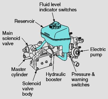
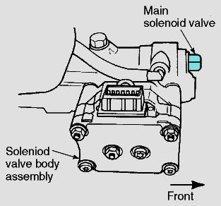
 Page 1 of 5 Chassis and Drivetrain 42 Brakes Anti-lock Brake System (ABS) 4-Wheel Electronic Traction Control System (4-ETS) Electronic Brake Proportioning (EBP) System Description The hydraulic pressure
DIAGNOSIS AND TESTING
 206-09-1 Vehicle Dynamic Systems 206-09-1 DIAGNOSIS AND TESTING Anti-Lock Control Traction Control and Stability Assist Special Tool(s) Principles of Operation 73III Automotive Meter 105-R0057 or equivalent
 Page 1 of 23 593: Brake control system V70 (00-08), 2004, B5244S2, M56, L.H.D, YV1SW65S241436824, 436824 16/7/2018 PRINT 593: Brake control system ABS control ABS function Active yaw control Active yaw
ABS, 4-ETS and EBP BRAKES ANTI-LOCK BRAKE SYSTEM (ABS) 4-WHEEL ELECTRONIC TRACTION CONTROL SYSTEM (4-ETS) ELECTRONIC BRAKE PROPORTIONING (EBP)
 4-WHEEL ELECTRONIC TRACTION CONTROL SYSTEM (4-ETS) ELECTRONIC BRAKE PROPORTIONING (EBP)") 1 of 9 4/27/2008 7:52 AM Home Account Contact ALLDATA Log Out Help Select Vehicle New TSBs Technician's Reference Component Search: METRO TOYOTA OK 2002 Mercedes Benz Truck ML 320 (163.154) V6-3.2L (112.942)
1 of 9 4/27/2008 7:52 AM Home Account Contact ALLDATA Log Out Help Select Vehicle New TSBs Technician's Reference Component Search: METRO TOYOTA OK 2002 Mercedes Benz Truck ML 320 (163.154) V6-3.2L (112.942)
Document ID# Chevrolet/Geo Corvette
 Page 1 of 10 Document ID# 426762 1999 Chevrolet/Geo Corvette Print ABS Description Brake Pressure Modulator Valve (BPMV) FIGURE EBTCM/BPMV(c) (1) Electronic Brake and Traction Control
The parking brake is an electrically actuated system that operates drum brakes integrated into the rear brake discs. The
 Page 1 of 15 Published: Oct 22, 2004 Parking Brake COMPONENT LOCATIONS Item Part Number Description 1 Clutch pedal position sensor (manual transmission models only) 2 Parking brake indicators (all except
DESCRIPTION & OPERATION
 DESCRIPTION & OPERATION ANTI-LOCK BRAKING 1998-99 BRAKES Anti-Lock/TCS - Corvette The Anti-Lock Brake System (ABS) and Traction Control System (TCS) increases vehicle control during severe deceleration
FOUR-WHEEL ANTI-LOCK BRAKE SYSTEM (4ABS)
") 35B-1 GROUP 35B FOUR-WHEEL ANTI-LOCK BRAKE SYSTEM (4ABS) CONTENTS GENERAL INFORMATION 35B-2 35B-6 SENSOR 35B-6 ACTUATORS 35B-6 ABS-ECU 35B-7 35B-2 The ABS that ensures directional stability and controllability
35B-1 GROUP 35B FOUR-WHEEL ANTI-LOCK BRAKE SYSTEM (4ABS) CONTENTS GENERAL INFORMATION 35B-2 35B-6 SENSOR 35B-6 ACTUATORS 35B-6 ABS-ECU 35B-7 35B-2 The ABS that ensures directional stability and controllability
DTC P Shift Solenoid Circuit Electrical
 1998 Pontiac Grand Prix DTC P0753 1-2 Shift Solenoid Circuit Electrical Circuit Description The 1-2 Shift Solenoid Valve (1-2 SS Valve) controls the fluid flow acting on the 1-2 and 3-4 shift valve. The
ANTI-LOCK BRAKE SYSTEM
 ANTI-LOCK BRAKE SYSTEM 1992 Infiniti G20 1990-92 BRAKES Infiniti Anti-Lock Brake System Infiniti; G20, M30, Q45 DESCRIPTION & OPERATION The Anti-Lock Brake System (ABS) prevents wheel lock-up during abrupt
1995 Honda Accord LX. ANTI-LOCK BRAKE SYSTEM' ' BRAKES Honda - Anti-Lock
 TROUBLE SHOOTING ANTI-LOCK (ABS) WARNING LIGHT NOTE: ABS system is okay if ABS warning light goes out after engine is started. Diagnostic Trouble Code (DTC) Recognition 1. ABS control unit recognizes system
Cruise Control Diagnosis
 1999 Pontiac Firebird Cruise Control Diagnosis Circuit Description The Cruise Control system is a speed control system that maintains a desired vehicle speed under normal driving conditions. The cruise
ABS LOCATION OF COMPONENTS - ABS UP TO 99MY. 4. Front and rear sensors/exciter rings 5. Pressure Conscious Reducing Valve (PCRV) 6.
 6.") ABS LOCATION OF COMPONENTS - ABS UP TO 99MY 1. Relays and fuses 2. ABS Electronic Control Unit (ECU) 3. Brake booster/abs modulator unit 4. Front and rear sensors/exciter rings 5. Pressure Conscious Reducing
ABS LOCATION OF COMPONENTS - ABS UP TO 99MY 1. Relays and fuses 2. ABS Electronic Control Unit (ECU) 3. Brake booster/abs modulator unit 4. Front and rear sensors/exciter rings 5. Pressure Conscious Reducing
SECTION Anti-Lock Brake System (ABS) and Stability Control
 and Stability Control") 206-09-i Anti-Lock Brake System (ABS) and Stability Control 206-09-i SECTION 206-09 Anti-Lock Brake System (ABS) and Stability Control CONTENTS PAGE DIAGNOSIS AND TESTING Anti-Lock Control... 206-09-2
206-09-i Anti-Lock Brake System (ABS) and Stability Control 206-09-i SECTION 206-09 Anti-Lock Brake System (ABS) and Stability Control CONTENTS PAGE DIAGNOSIS AND TESTING Anti-Lock Control... 206-09-2
Brake System Operation
 Brake System Brake System Operation Donald Jones Brookhaven College Master cylinder Brake lines Hydraulic valves Disc brakes Drum brakes Power assist unit Parking brake Antilock system Brake System Functions
Conventional Cruise Control
 About Conventional Cruise Control Conventional Cruise Control Conventional Cruise Control is a driving support system intended to allow more comfortable driving on expressways, freeways and interstate
2002 Buick Rendezvous - AWD
 2002 Buick Rendezvous - AWD DTC P0410 Description The control module activates the secondary air injection (AIR) system by grounding both the pump relay and the vacuum control solenoid control circuits.
System overview. Introduction. Copyright 2004 Volvo Car Corporation. All rights reserved.
 "VCC141172 EN 20090206" 1(40) System overview Introduction The Mark25 brake control system The Mark 25 brake control system with the brake control module (BCM) is an electronic control system which prevents
codigos error OBD2 genericos
 ucables.com Tecnologias de diagnostico y reparacion de automoviles C - Generic OBD-II Chassis Codes C0000 - Vehicle Speed Information Circuit Malfunction C0035 - Left Front Wheel Speed Circuit Malfunction
ANTI-LOCK BRAKES. Section 9. Fundamental ABS Systems. ABS System Diagram
 ANTI-LOCK BRAKES Fundamental ABS Systems Toyota Antilock Brake Systems (ABS) are integrated with the conventional braking system. They use a computer controlled actuator unit, between the brake master
Hydraulic Brake System and Trailer Brake Inspection Procedure
 Summary Created: April 26, 2012 Revised: April 27, 2016 Revised: April 27, 2017 This Inspection Bulletin describes inspection procedures and operating information for commercial motor vehicles and trailers
2001 Chevrolet Corvette ACCESSORIES & EQUIPMENT Cruise Control Systems - Corvette
 2001 ACCESSORIES & EQUIPMENT Cruise Control Systems - Corvette DESCRIPTION Cruise control is a speed control system that maintains a desired vehicle speed under normal driving conditions. Steep grades
Module 11: Antilock Brakes Systems
 ÂÂ ABS Brake System Antilock Brake System Operation Principles of ABS Braking ABS Master Cylinder Hydraulic Control Unit Wheel Speed Sensors ABS Electronic Control Unit Terms and Definitions Purposes for
capacity due to increased traction; particularly advantageous on road surfaces
 42-800 Design and function of acceleration slip control (ASR I) A. General B. Driving with ASR I C. Overall function of ASR I D. Location of components E. Individual functions A. General The acceleration
DESCRIPTION. Chrysler NCV3 Service Info Section 08 > Electronic Modules > MODULE, Transmission Control Information
 DESCRIPTION The transmission control module (TCM) receives, processes and sends various digital and analog signals related to the automatic transmission. In addition, it processes information received
Text in Illustration
 ON-VEHICLE INSPECTION If using a dropper to adjust the fluid amount, make sure that the dropper has not been used with mineral oils, water or deteriorated brake fluid. Sealed areas may deteriorate and
DTC P Shift Solenoid Circuit Electrical
 1998 Pontiac Grand Prix DTC P0753 1-2 Shift Solenoid Circuit Electrical Circuit Description The 1-2 Shift Solenoid Valve Assembly (1-2 SS Valve Assy.) controls the transmission fluid pressure on the 1-2
OPERATION. 2. SPIRAL CABLE A spiral cable is used as an electrical joint from the vehicle body side to the steering wheel.
 RS2 RS0SQ01 OPERATION 1. STEERING WHEEL PAD (with AIRBAG) The inflater and bag of the SRS are stored in the steering wheel pad and cannot be disassembled. The inflater contains a squib, igniter charge,
CONDITIONS FOR RUNNING THE DTC
 SYSTEM DESCRIPTION The powertrain control module (PCM) uses information from the crankshaft position (CKP) sensor and the camshaft position (CMP) sensor in order to determine when an engine misfire is
HECU Clock frequency 32 MHz 50 MHz Memory 128 KB 512 KB Switch Orifice Orifice. Operating temperature - 40 C to 150 C - 40 C to 150 C
 489000 113 1. SPECIFICATION Unit Description Specification ABS ESP HECU Clock frequency 32 MHz 50 MHz Memory 128 KB 512 KB Switch Orifice Orifice Wheel speed sensor ABS / ESP CBS Operating temperature
ANTI-LOCK BRAKE SYSTEM - REAR WHEEL
 ANTI-LOCK BRAKE SYSTEM - REAR WHEEL 1994 Nissan Pickup 1994 BRAKES Nissan - Rear Anti-Lock Pathfinder, Pickup DESCRIPTION In 2WD mode, Rear Anti-Lock Brake System (RABS) helps the driver to maintain steering
35C-1 GROUP 35C CONTENTS FEATURES... 35C-2 SYSTEM OPERATION... 35C-16 CONSTRUCTION DESCRIPTION... 35C-5
 35C-1 GROUP 35C CONTENTS FEATURES.................... 35C-2 SYSTEM OPERATION............ 35C-16... 35C-5 35C-2 FEATURES Anti-skid Brake System/Active Stability System (ABS/active stability system) is available
SECTION 1-6 OPERATION OF INSTRUMENTS AND CONTROLS 05 HIGHLANDER_U (L/O 0409) Gauges, Meters and Service reminder indicators
 Gauges, Meters and Service reminder indicators") SECTION 1-6 OPERATION OF INSTRUMENTS AND CONTROLS Gauges, Meters and Service reminder indicators Fuel gauge................................................ 132 Engine coolant temperature gauge...........................
SECTION 1-6 OPERATION OF INSTRUMENTS AND CONTROLS Gauges, Meters and Service reminder indicators Fuel gauge................................................ 132 Engine coolant temperature gauge...........................
DIAGNOSTIC TROUBLE CODE CHART
 50 DTC chart of ABS DIAGNOSTIC TROUBLE CODE CHART HINT: If a malfunction code is displayed during the DTC check, check the circuit indicated by the DTC. For details of each code, refer to the respective
SECONDARY SERVICE EXTERIOR R-12DC VALVE (MODEL WITH 4 VERTICAL DELIVERY PORTS) DELIVERY COVER SECONDARY RELAY PISTON VALVE RETAINER INLET EXHAUST
 DELIVERY COVER SECONDARY RELAY PISTON VALVE RETAINER INLET EXHAUST") SD-03-1068 Bendix R-12DC Relay Valve with Biased Double Check PRIMARY SECONDARY EXTERIOR R-12DC (MODEL WITH 4 VERTICAL DELIVERY PORTS) SUPPLY (2) EXTERIOR R-12DC (MODEL WITH 2 HORIZONTAL PORTS) DELIVERY
SD-03-1068 Bendix R-12DC Relay Valve with Biased Double Check PRIMARY SECONDARY EXTERIOR R-12DC (MODEL WITH 4 VERTICAL DELIVERY PORTS) SUPPLY (2) EXTERIOR R-12DC (MODEL WITH 2 HORIZONTAL PORTS) DELIVERY
OPERATION. 2. SPIRAL CABLE (in COMBINATION SWITCH) A spiral cable is used as an electrical joint from the vehicle body side to the steering wheel.
 A spiral cable is used as an electrical joint from the vehicle body side to the steering wheel.") RS2 SUPPLEMENTAL RESTRAINT SYSTEM RS0FR03 OPERATION 1. STEERING WHEEL PAD (with AIRBAG) The inflater and bag of the SRS are stored in the steering wheel pad and cannot be disassembled. The inflater contains
RS2 SUPPLEMENTAL RESTRAINT SYSTEM RS0FR03 OPERATION 1. STEERING WHEEL PAD (with AIRBAG) The inflater and bag of the SRS are stored in the steering wheel pad and cannot be disassembled. The inflater contains
Automated Control Electronics (ACE ) System Operation and Diagnostics
 System Operation and Diagnostics") Commercial Products Automated Control Electronics (ACE ) System Operation and Diagnostics PART NO. 98962SL This page is intentionally blank. Table of Contents Introduction... 1 Controller Operation and
Commercial Products Automated Control Electronics (ACE ) System Operation and Diagnostics PART NO. 98962SL This page is intentionally blank. Table of Contents Introduction... 1 Controller Operation and
International Medium Duty Full Power Hydraulic Brakes
 A N AV I S TA R C O M PA N Y International Medium Duty Full Power Hydraulic Brakes Study Guide TMT-040701 Study Guide International Medium Duty Full Power Hydraulic Brakes TMT-040701 2007 International
TABLE OF CONTENTS 1.1 SYSTEM COVERAGE SIX-STEP TROUBLESHOOTING PROCEDURE SYSTEM DESCRIPTION AND FUNCTIONAL OPERATION...
 TABLE OF CONTENTS 1.0 INTRODUCTION...1 1.1 SYSTEM COVERAGE...1 1.2 SIX-STEP TROUBLESHOOTING PROCEDURE...1 2.0 INDENTIFICATION OF SYSTEM...1 3.0 SYSTEM DESCRIPTION AND FUNCTIONAL OPERATION...1 3.1 ESP...1
DIAGNOSIS AND TESTING
 307-01B-1 DIAGNOSIS AND TESTING Special Testing Procedures The special tests are designed to aid the technician in diagnosing the hydraulic and mechanical portion of the transmission. Engine Idle speed
1998 E-Series Workshop Manual
 SECTION 206-09A: Anti-Lock Control Rear DIAGNOSIS AND TESTING Procedure revision date: 02/08/2000 Anti-Lock Control Refer to Wiring Diagrams Cell 42, Speed Control for schematic and connector information.
There are 2 ways of brake fluid replacement: using the Techstream or not using the Techstream.
 REPLACEMENT HINT: There are 2 ways of brake fluid replacement: using the Techstream or not using the Techstream. Perform fluid replacement with park (P) selected and the parking brake applied. As brake
MK - JEEP COMPASS/PATRIOT - 2.4L 4 CYL DOHC 16V DUAL V.V.T.
 9 - MK - JEEP COMPASS/PATRIOT -.4L 4 CYL DOHC 6V DUAL V.V.T. C6-ABS PUMP MOTOR SUPPLY LOW VOLTAGE BATT A A (TIPM) FUSE 5 7 C TIPM A9 RD/DB FUSED B(+) (PUMP) ANTI-LOCK GROUND 6 47 GROUND Z99 BK/WT Z99 BK/WT
9.1 Traction Systems (ASR, ETS) and Speed-sensitive Power Steering (SPS) Contents
 and Speed-sensitive Power Steering (SPS) Contents") 9.1 Traction Systems (ASR, TS) and Speed-sensitive Power Steering (SPS) Contents 9.1 Models 129, 140 as of 06/94 up to 08/95 Page Diagnosis Function Test (ASR only).......................... 11/1 Diagnostic
9.1 Traction Systems (ASR, TS) and Speed-sensitive Power Steering (SPS) Contents 9.1 Models 129, 140 as of 06/94 up to 08/95 Page Diagnosis Function Test (ASR only).......................... 11/1 Diagnostic
35A-1 SERVICE BRAKES CONTENTS BASIC BRAKE SYSTEM ANTI-SKID BRAKING SYSTEM (ABS) <2WD> ACTIVE STABILITY CONTOROL (ASC) SYSTEM
 <2WD> ACTIVE STABILITY CONTOROL (ASC) SYSTEM") 35A-1 SERVICE BRAKES CONTENTS BASIC BRAKE SYSTEM... 35A ANTI-SKID BRAKI SYSTEM (ABS) ... 35B ACTIVE STABILITY CONTOROL (ASC) SYSTEM... 35C 35A-2 BASIC BRAKE SYSTEM General/On-vehicle Service GENERAL
35A-1 SERVICE BRAKES CONTENTS BASIC BRAKE SYSTEM... 35A ANTI-SKID BRAKI SYSTEM (ABS) ... 35B ACTIVE STABILITY CONTOROL (ASC) SYSTEM... 35C 35A-2 BASIC BRAKE SYSTEM General/On-vehicle Service GENERAL
Honda Accord/Prelude
 Honda Accord/Prelude 1984-1995 In Tank Fuel Pumps TEST 1. Turn the ignition OFF. 2. On the Accord, remove the screws securing the underdash fuse box to its mount. Remove the fuel cut off relay from the
The following rear differential is provided for the off-road package models. BD20B (with Differential Lock Actuator)
") 6 4RUNNER NEW FEATURES NEW FEATURES DIFFERENTIAL (OFF-ROAD PACKAGE MODELS) 1. General The following rear differential is provided for the off-road package models. Rear Differential Lock Actuator 233CH46
6 4RUNNER NEW FEATURES NEW FEATURES DIFFERENTIAL (OFF-ROAD PACKAGE MODELS) 1. General The following rear differential is provided for the off-road package models. Rear Differential Lock Actuator 233CH46
1. INTRODUCTION. Anti-lock Braking System
 1. INTRODUCTION Car manufacturers world wide are vying with each other to invent more reliable gadgets there by coming closer to the dream of the Advanced safety vehicle or Ultimate safety vehicle, on
ANTI-LOCK BRAKE SYSTEM
 ANTI-LOCK BRAKE SYSTEM 1993 Mitsubishi Diamante 1993 BRAKES Mitsubishi - Anti-Lock Brake System Diamante DESCRIPTION The Anti-Lock BRAKE SYSTEM (ABS) is designed to prevent wheel lock-up during heavy braking.
SYSTEM OPERATION IMPORTANT CAUTIONS
 SYSTEM OPERATION The system is turned on by placing the gear shift lever in the reverse position. The green light on the cab Control Box will illuminate to indicate the system is operating. When an object
DTC Summaries. W5A-580 Transmission Control System 1998 MY
 DTC Summaries W5A-580 Transmission Control System 1998 MY OBD II MONITORING CONDITIONS: When testing for OBD II DTC reoccurrence, it can be determined if the Service Drive Cycle was of sufficient length
Electromechanical parking brake
 TRW Automotive Aftermarket Electromechanical parking brake VW SHARAN (7N1, 7N2), SEAT ALHAMBRA (710, 711) PUBLICATION XZB4058GB WARNING Health risk! Inhalation of brake dusts may result in serious damage
Brake Bleeding: Service and Repair
 2008 Lexus GS 460 V8-4.6L (1UR-FSE) Copyright 2013, ALLDATA 10.52SS Page 1 Brake Bleeding: Service and Repair BRAKE: BRAKE FLUID (for 1UR-FSE): BLEEDING BRAKE: BRAKE FLUID CAUTION: Bleeding without the
Pressing and holding the + RES switch, when the Cruise Control System is engaged, will allow the vehicle to
 CRUISE CONTROL DESCRIPTION AN... CRUISE CONTROL DESCRIPTION AND OPERATION (CRUISE CONTROL) Document ID# 2088041 Cruise Control Description and Operation Cruise control is a speed control system that maintains
Continuously Variable Transaxle Specification. Forward/Reverse Switching Mechanism Double Pinion Type Planetary Gear
 CVT SYSTEM > GENERAL OUTLINE 1. A newly developed K41B Continuously Variable Transaxle (CVT) is used for the1nr-fe engine models. 2. The K41B CVT, including a pair of the pulleys and the belt in the shift
VEHICLE DYNAMICS CONTROL (VDC)
") VEHICLE DYNAMICS CONTROL (VDC) SYSTEM 1. Vehicle Dynamics Control (VDC) System A: GENERAL The vehicle dynamics control (VDC) system is a driver assist system which enhances vehicle s running stability
VEHICLE DYNAMICS CONTROL (VDC) SYSTEM 1. Vehicle Dynamics Control (VDC) System A: GENERAL The vehicle dynamics control (VDC) system is a driver assist system which enhances vehicle s running stability
OPERATION. 2. SPIRAL CABLE (in COMBINATION SWITCH) A spiral cable is used as an electrical joint from the vehicle body side to the steering wheel.
 A spiral cable is used as an electrical joint from the vehicle body side to the steering wheel.") RS2 RS0UB01 OPERATION 1. STEERING WHEEL PAD (with AIRBAG) The inflater and bag of the SRS are stored in the steering wheel pad and cannot be disassembled. The inflater contains a squib, igniter charge,
RS2 RS0UB01 OPERATION 1. STEERING WHEEL PAD (with AIRBAG) The inflater and bag of the SRS are stored in the steering wheel pad and cannot be disassembled. The inflater contains a squib, igniter charge,
BE 66 POWER WINDOW CONTROL PARTS LOCATION
 BE66 POWER WINDOW CONTROL SYSTEM PARTS LOCATION BE67 TROUBLESHOOTING The table below will be useful for you in troubleshooting these electrical problems. The most likely causes of the malfunction are shown
OPERATOR S MANUAL HWH COMPUTER-CONTROLLED 2000 SERIES LEVELING SYSTEM. FEATURING: Single Step Touch Panel Control Air Leveling
 OPERATOR S MANUAL HWH COMPUTER-CONTROLLED 000 SERIES LEVELING SYSTEM R HWH CORPORATION R FEATURING: Single Step Touch Panel Control Air Leveling HWH COMPUTERIZED LEVELING LEVEL AIR EXCESS SLOPE MODE DUMP
BRAKE CONTROL SYSTEM SECTION CONTENTS F BRAKES BRC-1 ABS BRC
 F BRAKES A SECTION BRAKE CONTROL SYSTEM B C D CONTENTS E ABS PRECAUTIONS... 3 Precautions for Supplemental Restraint System (SRS) AIR BAG and SEAT BELT PRE-TEN- SIONER... 3 Precautions for Brake System...
HOW TO PROCEED WITH TROUBLESHOOTING
 2005 BRAKES Anti-Lock Brake System With Electronic Brake Force Distribution (EBD) - Diagnostics - RAV4 HOW TO PROCEED WITH TROUBLESHOOTING Troubleshoot in accordance with the following procedures. Fig.
200C II BRAKE SYSTEM
 200C II BRAKE SYSTEM The braking system on the 200C II Kress Coal Hauler uses hydraulic oil pressure from both the System and Steering accumulator circuits. Using oil from both circuits provides braking
COVER. Bendix ATR-6 Antilock. Traction Relay Valves DELIVERY PORTS (6) FIGURE 1 - BENDIX ATR-6 (AND ATR-3 ) ANTILOCK TRACTION RELAY VALVES
 FIGURE 1 - BENDIX ATR-6 (AND ATR-3 ) ANTILOCK TRACTION RELAY VALVES") SD-13-4861 Bendix ATR-6 and ATR-3 Antilock Traction Relay Valves 2 PIN SOLENOID CONNECTOR Bendix ATR-3 Antilock Traction Relay Valves CONTROL SOLENOID CONTROL PORT COVER Bendix ATR-6 Antilock Traction
SD-13-4861 Bendix ATR-6 and ATR-3 Antilock Traction Relay Valves 2 PIN SOLENOID CONNECTOR Bendix ATR-3 Antilock Traction Relay Valves CONTROL SOLENOID CONTROL PORT COVER Bendix ATR-6 Antilock Traction
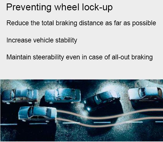
ABS keeps the vehicle steerable, even during an emergency braking
 ABS keeps the vehicle steerable, even during an emergency braking under all road conditions 1 Contents! Safety systems in vehicles! Why do you need ABS?! How does ABS work?! What are the benefits of ABS?!
ATASA 5 th. ABS & Traction Control Systems. Please Read The Summary
 ATASA 5 TH Study Guide Chapter 51 Pages: 1506 1534 Antilock Brake Systems 59 Points Please Read The Summary Before We Begin Keeping in mind the Career Cluster of Transportation, Distribution & Logistics
PRE CHECK 1. DIAGNOSIS SYSTEM
 DI710 w/o Tachometer: w/ Tachometer: F18894 PRECHECK ANTILOCK BRAKE SYSTEM DI8CS03 1. DIAGNOSIS SYSTEM (a) Check the indicator. When the ignition switch is turned, check that the ABS warning light is on
Intelli-Feed Controller User s Manual Intelli-Feed Digital Tachometer and Hourmeter
 Intelli-Feed Controller User s Manual Intelli-Feed Digital Tachometer and Hourmeter Part #: 9047 Table of Contents: Table of Contents 2 Intelli-Feed TM User Interface 3 Equipment Diagnostic Indicators
OVERVIEW: This bulletin involves installing a new antilock brake control module.
 NUMBER: 08-035-00 GROUP: Electrical DATE: Nov. 10, 2000 This bulletin is supplied as technical information only and is not an authorization for repair. No part of this publication may be reproduced, stored
SELECT HIGH-LOW SYSTEM
 Page 1 of 15 Your satisfaction is my GREATEST CONCERN, and I'm happy to answer any follow-up questions you may have. You can contact me anytime@http://www.justanswer.com/car/expert-tyroneboman/ SELECT
SD Bendix TP-4 Tractor Protection Valve (Formerly VM-1) DESCRIPTION
 DESCRIPTION") SD-03-3653 Bendix TP-4 Tractor Protection Valve (Formerly VM-1) CIRCUIT DELIVERY PORT (SCD) PRIMARY CIRCUIT DELIVERY PORT (PCD) EMERG. STOP LIGHT SWITCH (TE-SLS) PORT EMERG. SUPPLY (TES) PORT MOUNTING
SD-03-3653 Bendix TP-4 Tractor Protection Valve (Formerly VM-1) CIRCUIT DELIVERY PORT (SCD) PRIMARY CIRCUIT DELIVERY PORT (PCD) EMERG. STOP LIGHT SWITCH (TE-SLS) PORT EMERG. SUPPLY (TES) PORT MOUNTING
SECTION 1 1 FEATURES ON NEW TOYOTA RAV4 EV. Overview of instruments and controls
 FEATURES ON NEW TOYOTA RAV4 EV Overview of instruments and controls SECTION 1 1 Instrument panel overview..................................... 2 Instrument cluster overview....................................
P0777-SECONDARY PRESSURE SOLENOID STUCK ON (LOW PRESSURE)
") 009 - MK - JEEP COMPASS/PATRIOT -.0L 4 CYL DOHC 6V DUAL V.V.T. P0777-SECONDARY STUCK ON (LOW ) / LINE SECONDARY ON/OFF 3 4 T0 DG/LB T9 T9 T60 YL/DB YL/LB YL/GY C C 3 C 4 C LINE SECONDARY ON/OFF MODULE-
009 - MK - JEEP COMPASS/PATRIOT -.0L 4 CYL DOHC 6V DUAL V.V.T. P0777-SECONDARY STUCK ON (LOW ) / LINE SECONDARY ON/OFF 3 4 T0 DG/LB T9 T9 T60 YL/DB YL/LB YL/GY C C 3 C 4 C LINE SECONDARY ON/OFF MODULE-
SECTION 2 5 OPERATION OF INSTRUMENTS AND CONTROLS. Gauges, Meters and Service reminder indicators
 SECTION 2 5 OPERATION OF INSTRUMENTS AND CONTROLS Gauges, Meters and Service reminder indicators Fuel gauge................................................ 122 Odometer and two trip meters................................
SD Bendix MC-12 Modulator Controller Assembly DESCRIPTION
 SD-13-4762 Bendix MC-12 Modulator Controller Assembly EC-12 CONTROLLER DIAGSTIC DISPLAY DIAGSTIC DISPLAY M-12 MODULATOR DELIVERY PORTS (4 VERTICAL) 14 PIN CONNECTOR CONTROL PORT DELIVERY PORTS (2 VERTICAL
SCHEMATIC AND ROUTING DIAGRAMS
 2004 ACCESSORIES & EQUIPMENT Cruise Control - Corvette SCHEMATIC AND ROUTING DIAGRAMS CRUISE CONTROL SCHEMATICS Fig. 1: Cruise Control Switch, Throttle Actuator Control Motor And Cruise Control Release
PRE CHECK. (b) In case of not using LEXUS hand held tester : Check the DTC. (1) Disconnect the short pin from DLC1.
 In case of not using LEXUS hand held tester : Check the DTC. (1) Disconnect the short pin from DLC1.") DI 412 DIAGNOSTICS F02852 PRE CHECK DI28T 01 1. DIAGNOSIS SYSTEM (a) Check the warning lights and buzzer. (1) Release parking brake pedal. (2) When the ignition switch is turned, check that the ABS and
DI 412 DIAGNOSTICS F02852 PRE CHECK DI28T 01 1. DIAGNOSIS SYSTEM (a) Check the warning lights and buzzer. (1) Release parking brake pedal. (2) When the ignition switch is turned, check that the ABS and
2004 BRAKES. Antilock Brake System - Corvette
 2004 BRAKES Antilock Brake System Corvette SPECIFICATIONS FASTENER TIGHTENING SPECIFICATIONS Fastener Tightening Specifications Specification Application Metric English BPMV Brake Pipe Fittings 16 N.m
Audi A6 Current Flow Diagram No. 14 / 1 Edition
 Стр. 1 из 7 Audi A6 Current Flow Diagram No. 14 / 1 Edition 01.1998 Anti-lock brake system (ABS) with electronic differential lock (EDL), traction control system (ASR/TCS) and electronic stability program
2012 MKT Workshop Manual. REMOVAL AND INSTALLATION Procedure revision date: 06/13/2011
 SECTION 205-05: Rear Drive Halfshafts REMOVAL AND INSTALLATION Procedure revision date: 06/13/2011 Halfshaft Special Tool(s) Axle Seal Protector 205-816 Front Hub Remover 205-D070 (D93P-1175-B) or equivalent
FOUR-WHEEL ANTI-LOCK BRAKE SYSTEM (4ABS)
") 35B-1 GROUP 35B FOUR-WHEEL ANTI-LOCK BRAKE SYSTEM (4ABS) CONTENTS GENERAL DESCRIPTION......... 35B-2 SENSORS..................... 35B-6 BRAKE MODULATOR (ABS-ECU).. 35B-9 SYSTEM OPERATION............ 35B-10
35B-1 GROUP 35B FOUR-WHEEL ANTI-LOCK BRAKE SYSTEM (4ABS) CONTENTS GENERAL DESCRIPTION......... 35B-2 SENSORS..................... 35B-6 BRAKE MODULATOR (ABS-ECU).. 35B-9 SYSTEM OPERATION............ 35B-10
SD Bendix R-7 Modulating Valve DESCRIPTION INVERTED R-7 VALVE
 SD-03-4504 Bendix R-7 Modulating Valve MOUNTING HOLE (2) PORT BALANCE PORT INLET SPRING PORT DELIVERY (2) SUPPLY PORT MOUNTING SURFACE INLET INLET SEAT BALANCE PISTON PISTON DOUBLE CHECK (SUPPLY PORT &
14.Diagnostic Procedure with Diagnostic Trouble Code (DTC)
") 14.Diagnostic Procedure with Diagnostic Trouble Code (DTC) A: DTC C2021 TIRE 1 AIR PRESSURE DECREASE Refer to DTC C2024 for diagnostic procedure.
14.Diagnostic Procedure with Diagnostic Trouble Code (DTC) A: DTC C2021 TIRE 1 AIR PRESSURE DECREASE Refer to DTC C2024 for diagnostic procedure.
Continuously Variable Transaxle Specification. Forward/Reverse Switching Mechanism Double Pinion Type Planetary Gear
 CVT SYSTEM > GENERAL OUTLINE 1. A newly developed K41A Continuously Variable Transaxle (CVT) is used for the1kr-fe engine models. 2. The K41A CVT, including a pair of the pulleys and the belt in the shift
CRUISE CONTROL SYSTEM OVERVIEW AND OPERATION PROCESS 1. CRUISE CONTROL SWITCH
 10-3 OVERVIEW AND OPERATION PROCESS 1. CRUISE CONTROL SWITCH The purpose of the cruise control system is to automatically maintain a vehicle speed set by the driver, without depressing the accelerator
PRE-CHECK USA: DI-224 DLC1 E 1 ABS WITH EBD & BA & TRAC & VSC SYSTEM 2WD: CANADA: 4WD:
 DI224 2WD: 4WD: USA: CANADA: F14323 PRECHECK DI8XO02 1. DIAGNOSIS SYSTEM (a) Inspect the battery positive voltage. Battery positive voltage: 10 14 V (b) Check the warning lights and buzzer. (1) Release
SECTION BR CONTENTS BRAKE SYSTEM IDX
 BRAKE SYSTEM SECTION BR GI MA EM PRECAUTIONS AND PREPARATION... 3 Supplemental Restraint System (SRS) AIR BAG and SEAT BELT PRE-TENSIONER... 3 Precautions for Brake System... 3 Commercial Service Tools...
CAUTION. Hydraulic Brakes. Braking Systems - Hydraulic
 Hydraulic Brakes Dexter offers several varieties of hydraulic trailer brakes. Your vehicle may be equipped with drum brakes or disc brakes. The hydraulic brakes on your trailer are much like those on your
P445 Series Electronic Lube Oil Control
 FANs 125, 121 s Section P Product/Technical Bulletin P445 Issue Date 0100 P445 Series Electronic Lube Oil The P445 Series Electronic Lube Oil is designed for use on refrigeration compressors equipped with
Ignition Lock Cylinder
 1998 Cadillac Deville 6L SFI DOHC 8cyl 1 of 7 9/7/2010 7:41 PM GM Cadillac Deville_Fleetwood_ELD_Seville 1990-1998 Ignition Lock Cylinder REMOVAL & INSTALLATION CAUTION When performing service around Supplemental
SD Bendix SR-5 Trailer Spring Brake Valve DESCRIPTION PORTS. 1-1/2" or 3/4" NPT Spring Brake Reservoir Mounting (SPR BK RES)
") SD-03-4516 Bendix SR-5 Trailer Spring Brake Valve PRESSURE PROTECTION SR-5 IDENTIFICATION HOLE 1/4 NPT (2) COVER* FIGURE 1 DESCRIPTION 1/4 NPT TRAILER 1/4 NPT SR-5 TRAILER *SHOWN WITH OPTIONAL ANTI-COMPOUNDING
SD-03-4516 Bendix SR-5 Trailer Spring Brake Valve PRESSURE PROTECTION SR-5 IDENTIFICATION HOLE 1/4 NPT (2) COVER* FIGURE 1 DESCRIPTION 1/4 NPT TRAILER 1/4 NPT SR-5 TRAILER *SHOWN WITH OPTIONAL ANTI-COMPOUNDING
ADR 38/04 trailer brake requirements Overview of the changes in the latest revision
 ADR 38/04 trailer brake requirements Overview of the changes in the latest revision ADR 38/04 trailer brake requirements Definitions Antilock System (ABS) - a service brake system that automatically controls
5 FEATURES DDEC FOR MBE900 AND MBE4000
 DDEC FOR MBE900 AND MBE4000 5 FEATURES Section Page 5.1 ANTI-LOCK BRAKE/AUTOMATIC TRACTION CONTROL SYSTEMS.. 5-5 5.2 COLD START... 5-7 5.3 CRUISE CONTROL... 5-11 5.4 DIAGNOSTICS... 5-19 5.5 DUAL SPEED
SUPPLEMENTAL RESTRAINT SYSTEM
 PRECAUTION CAUTION: PRIUS is equipped with SRS, which consists of a driver airbag, front passenger airbag, side airbag and curtain shield airbag. Failure to carry out service operations in the correct
Product Campaign Bulletin
 Nissan Ireland Cedar House Park West Business Park Nangor Road, Dublin 12 Product Campaign Bulletin REFERENCE: MODEL: SUBJECT: PIB-NES-DAS-13-001 E12 New Note TB E12 - New Note New Technology Systems 1)
Feature Description. Version History
 TA2 Malfunction Indicator Lamp (MIL) and Engine Protection Document Number: FD-0007 Author: J. Goodloe Version: 03 Publish Date: 2016-03-18 Feature Description Version History Version Date Modified Sections
Operation of the FFBH is enabled and disabled by the Automatic Temperature Control Module (ATCM).
.") Page 1 of 8 Published : Apr 22, 2004 Auxiliary Heater COMPONENT LOCATIONS Item Part Number Description 1 - Fuel line connection with fuel tank 2 - Auxiliary fuel pump 3 - Fuel fired booster heater GENERAL
Page 1 of 8 Published : Apr 22, 2004 Auxiliary Heater COMPONENT LOCATIONS Item Part Number Description 1 - Fuel line connection with fuel tank 2 - Auxiliary fuel pump 3 - Fuel fired booster heater GENERAL
SD Bendix E-7 Dual Brake Valve DESCRIPTION OPERATION APPLYING: NORMAL OPERATION - PRIMARY CIRCUIT PORTION
 SD-03-818 Bendix E-7 Dual Brake Valve DESCRIPTION The Bendix E-7 dual brake valve is a suspended, pedal-operated type brake valve with two separate supply and delivery circuits for service and emergency
WIRELESS CONTROL MODULE (WCM)
") 42C-1 GROUP 42C WIRELESS CONTROL MODULE (WCM) CONTENTS GENERAL INFORMATION 42C-2 42C-5 KEYLESS ENTRY FUNCTION 42C-5 IMMOBILIZER FUNCTION 42C-9 TIRE PRESSURE MONITORING SYSTEM (TPMS) FUNCTION 42C-10 WARNINGS/ALARMS
42C-1 GROUP 42C WIRELESS CONTROL MODULE (WCM) CONTENTS GENERAL INFORMATION 42C-2 42C-5 KEYLESS ENTRY FUNCTION 42C-5 IMMOBILIZER FUNCTION 42C-9 TIRE PRESSURE MONITORING SYSTEM (TPMS) FUNCTION 42C-10 WARNINGS/ALARMS
OPERATOR S MANUAL HWH COMPUTER-CONTROLLED 2000 SERIES LEVELING SYSTEM AND SPACEMAKER ROOM EXTENSION SYSTEMS
 HWH CORPORATION R OPERATOR S MANUAL HWH COMPUTER-CONTROLLED R 2000 SERIES LEVELING SYSTEM AND SPACEMAKER ROOM EXTENSION SYSTEMS R FEATURING: Touch Panel Leveling Control Air Leveling (With or Without Tag
1. BRAKE SYSTEM GENERAL INFORMATION
 4890-01 08-3 1. BRAKE SYSTEM GENERAL INFORMATION Front Disc 1) FRONT BRAKE For the front brake system, the ventilated disc type is applied regardless of the ABS/ system installation. Two 43 mm diameter