Original Series PLASTIC Pumps
|
|
|
- Crystal Boone
- 6 years ago
- Views:
Transcription


1 P4 Original Series PLASTIC Pumps Engineering Operation & Maintenance Simplify your process WIL E-06 REPLACES WIL E-05

2 TABLE OF CONTENTS SECTION 1 CAUTIONS READ FIRST! SECTION 2 WILDEN PUMP DESIGNATION SYSTEM SECTION 3 HOW IT WORKS (PUMP & AIR SYSTEMS) SECTION 4 DIMENSIONAL DRAWINGS SECTION 5 PERFORMANCE A. P4 PLASTIC Performance Curves Rubber-Fitted TPE-Fitted Reduced Stroke PTFE-Fitted Full Stroke PTFE-Fitted B. Suction Lift Curves SECTION 6 SUGGESTED INSTALLATION, OPERATION & TROUBLESHOOTING SECTION 7 DIRECTIONS FOR DISASSEMBLY/REASSEMBLY Pro-Flo Air Valve/Center Block Disassembly, Cleaning, Inspection Reassembly Hints & Tips PTFE Gasket Kit Installation SECTION 8 EXPLODED VIEW/PARTS LISTING P4 PLASTIC Full Stroke Diaphragm-Fitted, 3-Piece Center Section Reduced Stroke Diaphragm-Fitted, 3-Piece Center Section Piece Center Section SECTION 9 ELASTOMER OPTIONS
3 Section 1 CAUTIONS READ FIRST! CAUTION: Do not apply compressed air to the exhaust port pump will not function. CAUTION: Do not exceed 8.6 bar (125 psig) air supply pressure. CAUTION: Do not over lubricate air supply excess lubrication will reduce pump performance. TEMPERATURE LIMITS: Polypropylene 0 C to 79 C 32 F to 175 F PVDF 12 C to 107 C 10 F to 225 F PTFE PFA 7 C to 107 C 20 F to 225 F Neoprene 17.7 C to 93.3 C 0 F to 200 F Buna-N 12.2 C to 82.2 C 10 F to 180 F EPDM 51.1 C to C 60 F to 280 F Viton 40 C to C 40 F to 350 F Wil-Flex 40 C to C 40 F to 225 F Saniflex 28.9 C to C 20 F to 220 F Polyurethane 12.2 C to 65.6 C 10 F to 150 F PTFE 4.4 C to C 40 F to 220 F Tetra-Flex PTFE 4.4 C to C 40 F to 225 F CAUTION: When choosing pump materials, be sure to check the temperature limits for all wetted components. Example: Viton has a maximum limit of C (350 F) but polypropylene has a maximum limit of only 79 C (175 F). CAUTION: Maximum temperature limits are based upon mechanical stress only. Certain chemicals will significantly reduce maximum safe operating temperatures. Consult engineering guide for chemical compatibility and temperature limits. CAUTION: Always wear safety glasses when operating pump. If diaphragm rupture occurs, material being pumped may be forced out air exhaust. Plastic series pumps are made of virgin plastic and are not UV stabilized. Direct sunlight for prolonged periods can cause deterioration of plastics. WARNING: Prevention of static sparking If static sparking occurs, fire or explosion could result. Pump, valves, and containers must be grounded when handling flammable fluids and whenever discharge of static electricity is a hazard. To ground the Wilden Champ, all clamp bands must be grounded to a proper grounding point. CAUTION: Before any maintenance or repair is attempted, the compressed air line to the pump should be disconnected and all air pressure allowed to bleed from pump. Disconnect all intake, discharge and air lines. Drain the pump by turning it upside down and allowing any fluid to flow into a suitable container. CAUTION: Blow out air line for 10 to 20 seconds before attaching to pump to make sure all pipeline debris is clear. Use an in-line air filter. A 5µ (micron) air filter is recommended. NOTE: When installing PTFE diaphragms, it is important to tighten outer pistons simultaneously (turning in opposite directions) to ensure tight fit. NOTE: P4 PVDF and PFA pumps come standard from the factory with expanded PTFE gaskets installed in the diaphragm bead of the liquid chamber, in the T-section and in the ball and seat area. PTFE gaskets cannot be re-used. Consult PS-TG for installation instructions during reassembly. NOTE: Before starting disassembly, mark a line from each liquid chamber to its corresponding air chamber. This line will assist in proper alignment during reassembly. CAUTION: The P4 Plastic pump is not submersible. If your application requires your pump to be submersed, the T4 model can be used. CAUTION: Pumps should be flushed thoroughly with water before installation into process line. CAUTION: Tighten all hardware prior to installation. WIL E-06 1 WILDEN PUMP & ENGINEERING, LLC
4 Section 2 WILDEN PUMP DESIGNATION SYSTEM P4 ORIGINAL PLASTIC 38 mm (1-1/2") Pump Maximum Flow Rate: 352 lpm (93 gpm) LEGEND P4 / XXXXX / XXX / XX / XXX / XXXX MODEL O-RINGS VALVE SEAT VALVE BALLS DIAPHRAGMS AIR VALVE CENTER BLOCK OR CENTER SECTION AIR CHAMBERS OR CENTER SECTION WETTED PARTS & OUTER PISTON SPECIALTY CODE (if applicable) In the case where a center section is used instead of a center block, air chambers, and air valve, the designation will be as follows: Polypropylene = PPP, Acetal = LLL MATERIAL CODES WETTED PARTS & OUTER PISTON KK = PVDF / PVDF PP = POLYPROPYLENE / POLYPROPYLENE TT = PFA / PFA AIR CHAMBER/CENTER SECTION A = ALUMINUM C = PTFE COATED ALUMINUM L = ACETAL S = STAINLESS STEEL V = HALAR COATED ALUMINUM CENTER BLOCK / CENTER SECTION L = ACETAL P = POLYPROPYLENE AIR VALVE L = ACETAL P = POLYPROPYLENE DIAPHRAGMS BNS = BUNA-N (Red Dot) BNU = BUNA-N, ULTRA-FLEX (Red Dot) EPS = EPDM (Blue Dot) EPU = EPDM, ULTRA-FLEX (Blue Dot) FSS = SANIFLEX [Hytrel (Cream)] NES = NEOPRENE (Green Dot) NEU = NEOPRENE, ULTRA-FLEX (Green Dot) PUS = POLYURETHANE (Clear) TEU = PTFE W/EPDM BACK-UP (White) TSU = PTFE W/SANIFLEX BACK-UP (White) VTS = VITON (White Dot) VTU = VITON, ULTRA-FLEX WFS = WIL-FLEX [Santoprene (Orange Dot)] TSS = FULL STROKE PTFE W/SANIFLEX BACK-UP TWS = FULL STROKE PTFE W/WIL-FLEX BACK-UP VALVE BALL BN = BUNA-N (Red Dot) EP = EPDM (Blue Dot) FS = SANIFLEX [Hytrel (Cream)] FV = SANITARY VITON (Two White Dots) NE = NEOPRENE (Green Dot) PU = POLYURETHANE (Brown) TF = PTFE (White) VT = VITON (White Dot) WF = WIL-FLEX [Santoprene (Orange Dot)] VALVE SEAT K = PVDF P = POLYPROPYLENE T = PFA VALVE SEAT O-RING BN = BUNA-N PU = POLYURETHANE (Brown) TV = PTFE ENCAP. VITON SPECIALTY CODES 0100 Wil-Gard II 110V 0102 Wil-Gard II sensor wires ONLY 0103 Wil-Gard II 220V 0206 PFA coated hardware, Wil-Gard II sensor wires ONLY 0502 PFA coated hardware 0504 DIN flange 0506 DIN flange, PFA coated hardware 0512 Adapter block, no muffler,pro-flo, center section 0513 SS outer pistons 0560 Split manifold 0561 Split manifold, PFA coated hardware 0563 Split manifold, discharge ONLY 0564 Split manifold, inlet ONLY 0603 PFA coated hardware, Wil-Gard II 110V 0604 DIN flange, Wil-Gard II 220V 0606 DIN flange, PFA coated hardware, Wil-Gard II 220V 0608 PFA coated hardware, Wil-Gard II 220V 0612 Ultrapure, PFA coated hardware, male connections 0618 Ultrapure, PFA coated hardware, Wil-Gard II 110V, male connections 0622 Ultrapure, male connections 0624 Ultrapure, Wil-Gard II 110V, male connections 0660 Split manifold, Wil-Gard II 110V 0661 Split manifold PFA coated hardware, Wil-Gard II 110V NOTE: MOST ELASTOMERIC MATERIALS USE COLORED DOTS FOR IDENTIFICATION. Viton is a registered trademark of DuPont Dow Elastomers. WILDEN PUMP & ENGINEERING, LLC 2 WIL E-06
5 Section 3 HOW IT WORKS PUMP The Wilden diaphragm pump is an air-operated, positive displacement, self-priming pump. These drawings show flow pattern through the pump upon its initial stroke. It is assumed the pump has no fluid in it prior to its initial stroke. OUTLET OUTLET OUTLET CLOSED OPEN OPEN CLOSED OPEN CLOSED B A B A B A OPEN CLOSED CLOSED OPEN CLOSED OPEN INLET INLET Right Stroke Mid Stroke Left Stroke FIGURE 1 The air valve directs pressurized air to the back side of diaphragm A. The compressed air is applied directly to the liquid column separated by elastomeric diaphragms. The diaphragm acts as a separation membrane between the compressed air and liquid, balancing the load and removing mechanical stress from the diaphragm. The compressed air moves the diaphragm away from the center block of the pump. The opposite diaphragm is pulled in by the shaft connected to the pressurized diaphragm. Diaphragm B is on its suction stroke; air behind the diaphragm has been forced out to the atmosphere through the exhaust port of the pump. The movement of diaphragm B toward the center block of the pump creates a vacuum within chamber B. Atmospheric pressure forces fluid into the inlet manifold forcing the inlet valve ball off its seat. Liquid is free to move past the inlet valve ball and fill the liquid chamber (see shaded area). FIGURE 2 When the pressurized diaphragm, diaphragm A, reaches the limit of its discharge stroke, the air valve redirects pressurized air to the back side of diaphragm B. The pressurized air forces diaphragm B away from the center block while pulling diaphragm A to the center block. Diaphragm B is now on its discharge stroke. Diaphragm B forces the inlet valve ball onto its seat due to the hydraulic forces developed in the liquid chamber and manifold of the pump. These same hydraulic forces lift the discharge valve ball off its seat, while the opposite discharge valve ball is forced onto its seat, forcing fluid to flow through the pump discharge. The movement of diaphragm A toward the center block of the pump creates a vacuum within liquid chamber A. Atmospheric pressure forces fluid into the inlet manifold of the pump. The inlet valve ball is forced off its seat allowing the fluid being pumped to fill the liquid chamber. INLET FIGURE 3 At completion of the stroke, the air valve again redirects air to the back side of diaphragm A, which starts diaphragm B on its exhaust stroke. As the pump reaches its original starting point, each diaphragm has gone through one exhaust and one discharge stroke. This constitutes one complete pumping cycle. The pump may take several cycles to completely prime depending on the conditions of the application. HOW IT WORKS AIR DISTRIBUTION SYSTEM PILOT SPOOL MAIN SHAFT CENTER BLOCK MUFFLER PLATE SMALL END MUFFLER AIR VALVE SPOOL LARGE END END CAP Figure 1 The Pro-Flo patented air distribution system incorporates three moving parts: the air valve spool, the pilot spool, and the main shaft/diaphragm assembly. The heart of the system is the air valve spool and air valve. As shown in Figure 1, this valve design incorporates an unbalanced spool. The smaller end of the spool is pressurized continuously, while the large end is alternately pressurized and exhausted to move the spool. The spool directs pressurized air to one chamber while exhausting the other. The air causes the main shaft/ diaphragm assembly to shift to one side discharging liquid on one side and pulling liquid in on the other side. When the shaft reaches the end of its stroke, it actuates the pilot spool, which pressurizes and exhausts the large end of the air valve spool. The pump then changes direction and the same process occurs in the opposite direction, thus reciprocating the pump. WIL E-06 3 WILDEN PUMP & ENGINEERING, LLC
6 Section 4 DIMENSIONAL DRAWINGS P4 Plastic 38 mm (1-1/2") DIN (ANSI) LIQUID DISCHARGE F 13 mm (1/2") FNPT AIR INLET 19 mm (3/4") FNPT AIR EXHAUST D C E G B A J H 38 mm (1-1/2") DIN (ANSI) LIQUID DISCHARGE K L S R N M FLANGE T DIMENSIONS - P4 Plastic P ITEM METRIC (mm) STANDARD (inch) A B C D E F G H J K L M N P DIN (mm) ANSI (inch) R 99ø 3.9ø S 127ø 5.0ø WILDEN PUMP & ENGINEERING, LLC 4 WIL E-06
7 Section 5A P4 PLASTIC RUBBER-FITTED PERFORMANCE Height mm (20.8") Width mm (15.5") Depth mm (11.2") Est. Ship Weight...Polypropylene 16.8 kg (37 lbs) PVDF 21.3 kg (47 lbs) Air Inlet mm (1/2") Inlet mm (1-1/2") Outlet mm (1-1/2") Suction Lift m Dry (16') 7.92 m Wet (26') Displacement per Stroke l (0.314 gal.) 1 Max. Flow Rate lpm (92 gpm) Max. Size Solids mm (3/16") 1 Displacement per stroke was calculated at 4.8 bar (70 psig) air inlet pressure against a 2 bar (30 psig) head pressure. Example: To pump 159 lpm (40 gpm) against a discharge pressure head of 2.7 bar (40 psig) requires 4.1 bar (60 psig) and 30.6 Nm 3 /h (18 scfm) air consumption. (See dot on chart.) Caution: Do not exceed 8.6 bar (125 psig) air supply pressure. Flow rates indicated on chart were determined by pumping water. For optimum life and performance, pumps should be specified so that daily operation parameters will fall in the center of the pump performance curve. P4 PLASTIC TPE-FITTED Height mm (20.8") Width mm (15.5") Depth mm (11.2") Est. Ship Weight...Polypropylene 16.8 kg (37 lbs) PVDF 21.3 kg (47 lbs) Air Inlet mm (1/2") Inlet mm (1-1/2") Outlet mm (1-1/2") Suction Lift m Dry (13') 7.92 m Wet (26') Displacement per Stroke l (0.311 gal.) 1 Max. Flow Rate lpm (94 gpm) Max. Size Solids mm (3/16") 1 Displacement per stroke was calculated at 4.8 bar (70 psig) air inlet pressure against a 2 bar (30 psig) head pressure. Example: To pump 42 gpm (159 lpm) against a discharge pressure head of 2.7 bar (40 psig) requires 4.1 bar (60 psig) and 34 Nm 3 /h (20 scfm) air consumption. (See dot on chart.) Caution: Do not exceed 8.6 bar (125 psig) air supply pressure. Flow rates indicated on chart were determined by pumping water. For optimum life and performance, pumps should be specified so that daily operation parameters will fall in the center of the pump performance curve. WIL E-06 5 WILDEN PUMP & ENGINEERING, LLC
8 PERFORMANCE P4 PLASTIC REDUCED STROKE PTFE-FITTED Height mm (20.8") Width mm (15.5") Depth mm (11.2") Est. Ship Weight...Polypropylene 16.8 kg (37 lbs) PVDF 21.3 kg (47 lbs) PTFE PFA 23.9 kg (52 lbs) Air Inlet mm (1/2") Inlet mm (1-1/2") Outlet mm (1-1/2") Suction Lift m Dry (10' Dry) 7.47 m Wet (24.5') Displacement per Stroke l (0.139 gal.) 1 Max. Flow Rate lpm (69 gpm) Max. Size Solids mm (3/16") 1 Displacement per stroke was calculated at 4.8 bar (70 psig) air inlet pressure against a 2 bar (30 psig) head pressure. Example: To pump 125 lpm (33 gpm) against a discharge pressure head of 2.7 bar (40 psig) requires 4 bar (58 psig) and 45 Nm 3 /h (27 scfm) air consumption. (See dot on chart.) Caution: Do not exceed 8.6 bar (125 psig) air supply pressure. Flow rates indicated on chart were determined by pumping water. For optimum life and performance, pumps should be specified so that daily operation parameters will fall in the center of the pump performance curve. P4 PLASTIC FULL STROKE PTFE-FITTED Height mm (20.8 ) Width mm (15.5 ) Depth mm (11.2 ) Ship Weight... Polypropylene 16.8 kg (37 lbs.) PVDF 21.3kg (47 lbs.) PTFE PFA 23.9 kg (52 lbs.) Air Inlet...13 mm (1/2 ) Inlet...38 mm (1-1/2 ) Outlet...38 mm (1-1/2 ) Suction Lift m Dry (15.3 ) 9.3 m Wet (30.6 ) Disp. Per Stroke l (.27 gal.) 1 Max. Flow Rate lpm (92.9 gpm) Max. Size Solids mm (3/16 ) 1 Displacement per stroke was calculated at 4.8 bar (70 psig) air inlet pressure against a 2 bar (30 psig) head pressure. Example: To pump 76 GPM against a discharge head of 30 psigrequires 100 psig and 100 scfm air consumption. Caution: Do not exceed 8.6 bar (125 psig) air supply pressure. Flow rates indicated on chart were determined by pumping water. For optimum life and performance, pumps should be specified so that daily operation parameters will fall in the center of the pump performance curve. WILDEN PUMP & ENGINEERING, LLC 6 WIL E-06
9 Section 5B SUCTION LIFT CURVES P4 PLASTIC SUCTION LIFT CAPABILITY Suction lift curves are calibrated for pumps operating at 1,000' (305 m) above sea level. This chart is meant to be a guide only. There are many variables which can affect your pump s operating characteristics. The number of intake and discharge elbows, viscosity of pumping fluid, elevation (atmospheric pressure) and pipe friction loss all affect the amount of suction lift your pump will attain. WIL E-06 7 WILDEN PUMP & ENGINEERING, LLC
10 Section 6 SUGGESTED INSTALLATION The Pro-Flo model P4 has a 38 mm (1-1/2") inlet and 38 mm (1-1/2") outlet and is designed for flows to 354 lpm (94 gpm). The P4 Plastic pump is manufactured with wetted parts of pure, unpigmented, PTFE or polypropylene. The P4 Plastic is constructed with a polypropylene center block. A variety of diaphragms and o-rings are available to satisfy temperature, chemical compatibility, abrasion and flex concerns. The suction pipe size should be at least 38 mm (1-1/2") diameter or larger if highly viscous material is being pumped. The suction hose must be non-collapsible, reinforced type as the P4 is capable of pulling a high vacuum. Discharge piping should be at least 38 mm (1-1/2"); larger diameter can be used to reduce friction losses. It is critical that all fittings and connections are airtight or a reduction or loss of pump suction capability will result. For P4 Plastic models, Wilden offers 150 lb. standard and metric flanges. The following details should be noted when mating these to pipe works: A shore gasket that covers the entire ßflange face should be used. The gasket should be between 1.91 mm (.075") and 4.45 mm (.175") thickness. Mating flanges with flat as opposed to raised surfaces should be used for proper mechanical sealing. The flanges should be tightened to a minimum of 6.8 N m (5 ft-lbs) but no more than 13.5 N m (10 ft-lbs). INSTALLATION: Months of careful planning, study, and selection efforts can result in unsatisfactory pump performance if installation details are left to chance. Premature failure and long term dissatisfaction can be avoided if reasonable care is exercised throughout the installation process. LOCATION: Noise, safety, and other logistical factors usually dictate where equipment be situated on the production floor. Multiple installations with conflicting requirements can result in congestion of utility areas, leaving few choices for additional pumps. Within the framework of these and other existing conditions, every pump should be located in such a way that five key factors are balanced against each other to maximum advantage. ACCESS: First of all, the location should be accessible. If it s easy to reach the pump, maintenance personnel will have an easier time carrying out routine inspections and adjustments. Should major repairs become necessary, ease of access can play a key role in speeding the repair process and reducing total downtime. AIR SUPPLY: Every pump location should have an air line large enough to supply the volume of air necessary to achieve the desired pumping rate (see Section 5). Use air pressure up to a maximum of 8.6 bar (125 psig) depending on pumping requirements. For best results, the pumps should use a 5µ micron air filter, needle valve and regulator. The use of an air filter before the pump will insure that the majority of any pipeline contaminants will be eliminated. SOLENOID OPERATION: When operation is controlled by a solenoid valve in the air line, three-way valves should be used, thus allowing trapped air to bleed off and improving pump performance. Pumping volume can be set by counting the number of strokes per minute and multiplying by displacement per stroke. Sound levels are reduced below OSHA specifications using the standard Wilden muffler element. Other mufflers can be used but usually reduce pump performance. ELEVATION: Selecting a site that is well within the pump s dynamic lift capability will assure that loss-of-prime troubles will be eliminated. In addition, pump efficiency can be adversely affected if proper attention is not given to site location. PIPING: Final determination of the pump site should not be made until the piping problems of each possible location have been evaluated. The impact of current and future installations should be considered ahead of time to make sure that inadvertent restrictions are not created for any remaining sites. The best choice possible will be a site involving the shortest and straightest hook-up of suction and discharge piping. Unnecessary elbows, bends, and fittings should be avoided. Pipe sizes should be selected so as to keep friction losses within practical limits. All piping should be supported independently of the pump. In addition, the piping should be aligned so as to avoid placing stresses on the pump fittings. Flexible hose can be installed to aid in absorbing the forces created by the natural reciprocating action of the pump. If the pump is to be bolted down to a solid location, a mounting pad placed between the pump and the foundation will assist in minimizing pump vibration. Flexible connections between the pump and rigid piping will also assist in minimizing pump vibration. If quick-closing valves are installed at any point in the discharge system, or if pulsation within a system becomes a problem, a surge suppressor should be installed to protect the pump, piping and gauges from surges and water hammer. When pumps are installed in applications involving flooded suction or suction head pressures, a gate valve should be installed in the suction line to permit closing of the line for pump service. For P4 Plastic models, a non-raised surfaced-flange adapter should be utilized when mating to the pump s inlet and discharge manifolds for proper sealing. If the pump is to be used in a self-priming application, be sure that all connections are airtight and that the suction lift is within the model s ability. Note: Materials of construction and elastomer material have an effect on suction lift parameters. Please consult Wilden distributors for specifics. Pumps in service with a positive suction head are most efficient when inlet pressure is limited to bar (7 10 psig). Premature diaphragm failure may occur if positive suction is 10 psig and higher. THE MODEL P4 CHAMP WILL PASS 0.5 MM (3/16") SOLIDS. WHENEVER THE POSSIBILITY EXISTS THAT LARGER SOLID OBJECTS MAY BE SUCKED INTO THE PUMP, A STRAINER SHOULD BE USED ON THE SUCTION LINE. CAUTION: DO NOT EXCEED 8.6 BAR (125 PSIG) AIR SUPPLY PRESSURE. P4 PUMPS CANNOT BE SUBMERGED. FOR SUBMERGED APPLICATIONS, USE A WILDEN T4 PUMP. WILDEN PUMP & ENGINEERING, LLC 8 WIL E-06
11 SUGGESTED INSTALLATION AIR-OPERATED PUMPS: To stop the pump from operating in an emergency situation, simply close the shut-off valve (user supplied) installed in the air supply line. A properly functioning valve will stop the air supply to the pump, therefore stopping output. This shut-off valve should be located far enough away from the pumping equipment such that it can be reached safely in an emergency situation. NOTE: In the event of a power failure, the shutoff valve should be closed, if the restarting of the pump is not desirable once power is regained. WIL E-06 9 WILDEN PUMP & ENGINEERING, LLC
12 SUGGESTED OPERATION & MAINTENANCE OPERATION: The P4 is pre-lubricated, and does not require in-line lubrication. Additional lubrication will not damage the pump, however if the pump is heavily lubricated by an external source, the pump s internal lubrication may be washed away. If the pump is then moved to a non-lubricated location, it may need to be disassembled and re-lubricated as described in the ASSEMBLY/DISASSEMBLY INSTRUCTIONS. Pump discharge rate can be controlled by limiting the volume and/or pressure of the air supply to the pump (preferred method). An air regulator is used to regulate air pressure. A needle valve is used to regulate volume. Pump discharge rate can also be controlled by throttling the pump discharge by partially closing a valve in the discharge line of the pump. This action increases friction loss which reduces flow rate. (See Section 5.) This is useful when the need exists to control the pump from a remote location. When the pump discharge pressure equals or exceeds the air supply pressure, the pump will stop; no bypass or pressure relief valve is needed, and pump damage will not occur. The pump has reached a deadhead situation and can be restarted by reducing the fluid discharge pressure or increasing the air inlet pressure. The Wilden P4 pump runs solely on compressed air and does not generate heat, therefore your process fluid temperature will not be affected. MAINTENANCE AND INSPECTIONS: Since each application is unique, maintenance schedules may be different for every pump. Frequency of use, line pressure, viscosity and abrasiveness of process fluid all affect the parts life of a Wilden pump. Periodic inspections have been found to offer the best means for preventing unscheduled pump downtime. Personnel familiar with the pump s construction and service should be informed of any abnormalities that are detected during operation. RECORDS: When service is required, a record should be made of all necessary repairs and replacements. Over a period of time, such records can become a valuable tool for predicting and preventing future maintenance problems and unscheduled downtime. In addition, accurate records make it possible to identify pumps that are poorly suited to their applications. TROUBLESHOOTING Pump will not run or runs slowly. 1. Ensure that the air inlet pressure is at least 0.4 bar (5 psig) above startup pressure and that the differential pressure (the difference between air inlet and liquid discharge pressures) is not less than 0.7 bar (10 psig). 2. Check air inlet filter for debris (see recommended installation). 3. Check for extreme air leakage (blow by) which would indicate worn seals/bores in the air valve, pilot spool and main shaft. 4. Disassemble pump and check for obstructions in the air passageways or objects which would obstruct the movement of internal parts. 5. Check for sticking ball check valves. If material being pumped is not compatible with pump elastomers, swelling may occur. Replace ball check valves and seals with proper elastomers. Also, as the check valve balls wear out, they become smaller and can become stuck in the seats. In this case, replace balls and seats. 6. Check for broken inner piston which will cause the air valve spool to be unable to shift. 7. Remove plug from pilot spool exhaust. Pump runs but little or no product flows. 1. Check for pump cavitation; slow pump speed down to allow thick material to flow into the liquid chambers. 2. Verify that vacuum required to lift liquid is not greater than the vapor pressure of the material being pumped (cavitation). 3. Check for sticking ball check valves. If material being pumped is not compatible with pump elastomers, swelling may occur. Replace ball check valves and seals with proper elastomers. Also, as the check valve balls wear out, they become smaller and can become stuck in the seats. In this case, replace balls and seats. Pump air valve freezes. 1. Check for excessive moisture in compressed air. Either install a dryer or hot air generator for compressed air. Alternatively, a coalescing filter may be used to remove the water from the compressed air in some applications. Air bubbles in pump discharge. 1. Check for ruptured diaphragm. 2. Check tightness of outer pistons. (Refer to Section 8C.) 3. Check tightness of clamp bands and integrity of o-rings and seals, especially at intake manifold. 4. Ensure pipe connections are airtight. Product comes out air exhaust. 1. Check for diaphragm rupture. 2. Check tightness of outer pistons to shaft. WILDEN PUMP & ENGINEERING, LLC 10 WIL E-06

 inlet and outlet and is designed for flows up to 354 lpm (94 gpm).")

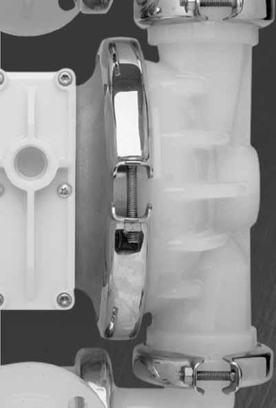
13 Section 7 PUMP DISASSEMBLY Tools Required: 1/2" Wrench Adjustable Wrench Vise equipped with soft jaws (such as plywood, plastic or other suitable material) CAUTION: Before any maintenance or repair is attempted, the compressed air line to the pump should be disconnected and all air pressure allowed to bleed from the pump. Disconnect all intake, discharge, and air lines. Drain the pump by turning it upside down and allowing any fluid to flow into a suitable container. Be aware of any hazardous effects of contact with your process fluid. The Wilden P4 has a 38 mm (1-1/2") inlet and outlet and is designed for flows up to 354 lpm (94 gpm). Its air distribution system is based on a revolutionary design which increases reliability and performance. The model P4 is available in injection molded polypropylene, PTFE PFA and PVDF wetted parts. NOTE: The model used for these instructions incorporates rubber diaphragms, balls, and seats. Models with PTFE diaphragms, balls and seats are the same except where noted. TK TK Step 1. Figure 1 Before starting disassembly, mark a line from each liquid chamber to its corresponding air chamber. This line will assist in proper alignment during reassembly. Step 2. Figure 2 Utilizing a 1/2" wrench, remove the two small clamp bands that fasten the discharge manifold to the liquid chambers. Step 3. Figure 3 Remove the discharge manifold to expose the valve balls and seats. Inspect ball cage area of manifold for excessive wear or damage. WIL E WILDEN PUMP & ENGINEERING, LLC


14 PUMP DISASSEMBLY Step 4. Figure 4 Remove the discharge valve balls and seats from the liquid chambers and inspect for nicks, gouges, chemical attack or abrasive wear. Replace worn parts with genuine Wilden parts for reliable performance. Step 5. Figure 5 Remove the two small clamp bands which fasten the intake manifold to the liquid chambers. Step 6. Figure 6 Lift intake manifold from liquid chambers and center section to expose intake valve balls and seats. Inspect ball cage area of liquid chambers for excessive wear or damage. Step 7. Figure 7 Remove valve seats and valve balls for inspection. Replace if necessary. Step 8. Figure 8 Remove small manifold clamp bands to inspect manifold o-rings. WILDEN PUMP & ENGINEERING, LLC 12 WIL E-06


 The outer")
.")
.")

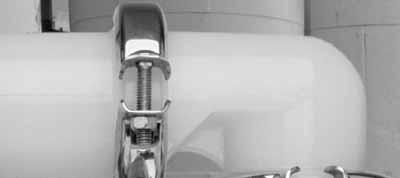
15 PUMP DISASSEMBLY Step 9. Figure 9 Remove one set of large clamp bands which secure one liquid chamber to the center section. Step 10. Figure 10 Lift liquid chamber away from center section to expose diaphragm and outer piston. Step 11. Figure 11 Using an adjustable wrench, or by rotating the diaphragm by hand, remove the diaphragm assembly. Step 12. Figure 12 Figure 13 Step 13. Figure 14 NOTE: Due to varying torque values, one of the following two situations may occur: 1) The outer piston, diaphragm and inner piston remain attached to the shaft and the entire assembly can be removed from the center section (Figure 12). 2) The outer piston, diaphragm and inner piston separate from the shaft which remains connected to the opposite side diaphragm assembly (Figure 13). Repeat disassembly instructions for the opposite liquid chamber. Inspect diaphragm assembly and shaft for signs of wear or chemical attack. Replace all worn parts with genuine Wilden parts for reliable performance. To remove diaphragm assembly from shaft, secure shaft with soft jaws (a vise fitted with plywood, plastic or other suitable material) to ensure shaft is not nicked, scratched or gouged. Using an adjustable wrench, remove diaphragm assembly from shaft. WIL E WILDEN PUMP & ENGINEERING, LLC

 air inlet connects the air supply to the center section.")


16 Section 8B DISASSEMBLY, CLEANING, INSPECTION Tools Required: 3/16" Hex Head Wrench 1/4" Hex Head Wrench Snap Ring Pliers O-Ring Pic AIR VALVE DISASSEMBLY: CAUTION: Before any maintenance or repair is attempted, the compressed air line to the pump should be disconnected and all air pressure allowed to bleed from the pump. Disconnect all intake, discharge, and air lines. Drain the pump by turning it upside down and allowing any fluid to flow into a suitable container. Be aware of hazardous effects of contact with your process fluid. The Wilden Plastic P4 utilizes a revolutionary Pro-Flo air distribution system. A 13 mm (1/2") air inlet connects the air supply to the center section. Proprietary composite seals reduce the co efficient of friction and allow the P4 to run lubefree. Constructed of polypropylene or Acetal, the Pro-Flo air distri bution system is designed to perform in on/off, non-freezing, non-stalling, tough duty applications. Step 1. Figure 1 Loosen the air valve bolts utilizing a 3/16" hex head wrench and then remove muffler plate screws. Step 2. Figure 2 Remove muffler plate and air valve bolts from air valve assembly exposing muffler gasket for inspection. Replace if necessary. Step 3. Figure 3 Lift away air valve assembly and remove air valve gasket for inspection. Replace if necessary. Step 4. Figure 4 Remove air valve end cap to expose air valve spool by simply lifting up on end cap once air valve bolts are removed. WILDEN PUMP & ENGINEERING, LLC 14 WIL E-06


17 DISASSEMBLY, CLEANING, INSPECTION Step 5. Figure 5 Remove air valve spool from air valve body by threading one air valve bolt into the end of the spool and gently sliding the spool out of the air valve body. Inspect seals for signs of wear and replace entire assembly if necessary. Use caution when handling air valve spool to prevent damaging seals. NOTE: Seals should not be remove from assembly. Seals are not sold separately. Step 6. Figure 6 Remove pilot spool retaining snap ring on both sides of center section with snap ring pliers. Step 7. Figure 7 Remove air chamber bolts with 1/4" hex head wrench. A Step 8. Figure 8 Remove pilot spool bushing from center block. Step 9. Figure 9 With o-ring pick, gently remove the o- ring from the opposite side of the center hole cut on the spool. Gently remove the pilot spool from sleeve and inspect for nicks or gouges and other signs of wear. Replace pilot sleeve assembly or outer sleeve o-rings if necessary. During re-assembly never insert the pilot spool into the sleeve with the center cut side first, this end incorporates the urethane o-ring and will be damaged as it slides over the ports cut in the sleeve. NOTE: Seals should not be removed from pilot spool. Seals are not sold separately. Step 10. Figure 10 Check center block Glyd rings for signs of wear. If necessary, remove Glyd rings with o-ring pick and replace. NOTE: Threaded sleeves (see A Figure 10) are removable and can be replaced if necessary. Sleeves can be press fit by hand. WIL E WILDEN PUMP & ENGINEERING, LLC
18 Section 8C REASSEMBLY HINTS & TIPS ASSEMBLY: Upon performing applicable maintenance to the air distribution system, the pump can now be reassembled. Please refer to the disassembly instructions for photos and parts placement. To reassemble the pump, follow the disassembly instructions in reverse order. The air distribution system needs to be assembled first, then the diaphragms and finally the wetted path. Please find the applicable torque specifications on this page. The following tips will assist in the assembly process. Lubricate air valve bore, center section shaft and pilot spool bore with NLGI grade 2 white EP bearing grease or equivalent. Clean the inside of the center section shaft bushing to ensure no damage is done to new Glyd ring seals. A small amount NLGI grade 2 white EP bearing grease can be applied to the muffler and air valve gaskets to locate gaskets during assembly. Make sure that the exhaust port on the muffler plate is centered between the two exhaust ports on the center section. Stainless bolts should be lubed to reduce the possibility of seizing during tightening. Use a mallet to tamp lightly on the large clamp bands to seat the diaphragm before tightening. GLYD RING INSTALLATION: PRE-INSTALLATION Once all of the old seals have been removed, the inside of the bushing should be cleaned to ensure no debris is left that may cause premature damage to the new seals. MAXIMUM TORQUE SPECIFICATIONS Description of Part Air Valve Outer Piston Small Clamp Band Large Clamp Band (Rubber-Fitted) Large Clamp Band (PTFE-Fitted) Air Chamber Screws (HSFHS 3/8"-16) Figure A Plastic Pumps 5.1 N m (45 in-lbs) 47.5 N m (35 ft-lbs) 9.6 N m (85 in-lbs) 18.6 N m (165 in-lbs) 18.6 N m (165 in-lbs) 47.5 N m (35 ft-lbs) INSTALLATION The following tools can be used to aid in the installation of the new seals: Needle Nose Pliers Phillips Screwdriver Electrical Tape Wrap electrical tape around each leg of the needle nose pliers (heat shrink tubing may also be used). This is done to prevent damaging the inside surface of the new seal. With a new seal in hand, place the two legs of the needle nose pliers inside the seal ring. (See Figure A.) Open the pliers as wide as the seal diameter will allow, then with two fingers pull down on the top portion of the seal to form kidney bean shape. (See Figure B.) Lightly clamp the pliers together to hold the seal into the kidney shape. Be sure to pull the seal into as tight of a kidney shape as possible, this will allow the seal to travel down the bushing bore easier. With the seal clamped in the pliers, insert the seal into the bushing bore and position the bottom of the seal into the correct groove. Once the bottom of the seal is seated in the groove, release the clamp pressure on the pliers. This will allow the seal to partially snap back to its original shape. After the pliers are removed, you will notice a slight bump in the seal shape. Before the seal can be properly resized, the bump in the seal should be removed as much as possible. This can be done with either the Phillips screwdriver or your finger. With either the side of the screwdriver or your finger, apply light pressure to the peak of the bump. This pressure will cause the bump to be almost completely eliminated. Lubricate the edge of the shaft with NLGI grade 2 white EP bearing grease. Slowly insert the center shaft with a rotating motion. This will complete the resizing of the seal. Perform these steps for the remaining seal. Figure B NEEDLE NOSE PLIERS GLYD RING TAPE WILDEN PUMP & ENGINEERING, LLC 16 WIL E-06
.")


19 Section 8D GASKET KIT INSTALLATION Only P4 PVDF pumps come standard with expanded PTFE Gasket Kits ( ). Carefully prepare sealing surfaces by removing all debris and foreign matter from diaphragm bead and all mating surfaces. If necessary, smooth or deburr all sealing surfaces. Mating surfaces must be properly aligned in order to ensure positive sealing characteristics. Step 1. Figure 1 Gently remove the adhesive covering from the back of the PTFE tape. Ensure that the adhesive strip remains attached to the PTFE tape. Step 2. Figure 2 Starting at any point, place the PTFE tape in the center of the diaphragm bead groove on the liquid chamber and press lightly on the tape to ensure that the adhesive holds it in place during assembly. Do not stretch the tape during placement in center of diaphragm bead groove. Step 3. Figure 3 The ends of the tape should overlap approximately 13 mm (1/2"). Proceed to install the PTFE tape on the remaining liquid chamber. Step 4. Figure 4 Carefully remove the protective covering from the back of the PTFE gasket attached to tape. Step 5. Figure 5 Install the valve ball, valve seat and o-ring. Step 6. Figure 6 Step 7. Figure 7 Center the gasket so that it evenly covers the o-ring and seat areas. Gently apply pressure to gasket to ensure the adhesive maintains a positive seal to stay in place during pump assembly. WIL E WILDEN PUMP & ENGINEERING, LLC
20 Section 8 EXPLODED VIEW AND PART LISTINGS P4 PLASTIC FULL STROKE DIAPHRAGM-FITTED/3-PIECE CENTER SECTION EXPLODED VIEW FULL STROKE PTFE-FITTED WILDEN PUMP & ENGINEERING, LLC 18 WIL E-06
21 EXPLODED VIEW AND PART LISTINGS P4 PLASTIC FULL STROKE DIAPHRAGM-FITTED/3-PIECE CENTER SECTION PARTS LISTING No. Part Description Qty. P4/PPAPP P4/KKAPP P4/PPCPP/0502 P4/KKCPP/ Pro-Flo Air Valve Assembly O-Ring (-225), End Cap (1.859" x.139") End Cap, Pro-Flo Screw, HHC, Air Valve (1/4" x 4.5") Screw, SHCS, x 1 3/4" Muffler Plate, Pro-Flo Gasket, Muffler Plate Gasket, Air Valve Center Block Assembly Bushing, Reducer, NPT/BSP Combo Nut, Square, 1/4" Sleeve, Threaded, Pro-Flo Center Block Removable Pilot Sleeve Assembly Shaft, Pro-Flo Glyd Ring Gasket, Center Block, Pro-Flo Air Chamber, Pro-Flo Screw, HSFHS, 3/8"-16 x 1" Retaining Ring Inner Piston Diaphragm 2 * * * * 22 Outer Piston Valve Seat Valve Seat, O-Ring (2.609" x.139") 4 * * * * 25 Valve Ball 4 * * * * 26 Chamber, Liquid Large Clamp Band Assy Small Clamp Band Assy Manifold, Discharge Elbow Manifold, Inlet Elbow Manifold, Tee Section Carriage Bolt, Large Clamp Band (5/16"-18 RHSN) Hex Nut, Large Clamp Band (5/16"-18) Carriage Bolt, Small Clamp Band (1/4"-20 RHSN) Hex Nut, Small Clamp Band (1/4"-20) Tee Section O-Ring (2.734" x.139") 4 * * * * 37 Muffler (Not shown) Pilot Spool Retaining O-Ring Diaphragm, Full Stroke PTFE, Primary Diaphragm, Full Stroke PTFE, Back-Up 2 * * * * 1 Air Valve Assembly includes item numbers 2 and 3. DIN Flange: Polypropylene = PVDF = Specialty Code = PFA-Coated Hardware *Refer to elastomer chart in Section 10. All boldface items are primary wear parts. WIL E WILDEN PUMP & ENGINEERING, LLC
22 EXPLODED VIEW AND PART LISTINGS P4 PLASTIC REDUCED STROKE DIAPHRAGM-FITTED/3-PIECE CENTER SECTION EXPLODED VIEW WILDEN PUMP & ENGINEERING, LLC 20 WIL E-06
23 EXPLODED VIEW AND PART LISTINGS P4 PLASTIC REDUCED STROKE DIAPHRAGM-FITTED/3-PIECE CENTER SECTION PARTS LISTING No. Part Description Qty. P4/PPAPP P4/KKAPP P4/TTAPP P4/PPCPP/0502 P4/KKCPP/0502 P4/TTCPP/ Pro-Flo Air Valve Assembly* O-Ring (-225), End Cap (1.859" x.139") End Cap, Pro-Flo Screw, HHC, Air Valve (1/4" x 4.5") Screw, SHCS, x 1 3/4" Muffler Plate, Pro-Flo Gasket, Muffler Plate Gasket, Air Valve Center Block Assembly Bushing, Reducer, NPT/BSP Combo Nut, Square, 1/4" Sleeve, Threaded, Pro-Flo Center Block Removable Pilot Sleeve Assembly Shaft, Pro-Flo Glyd Ring Gasket, Center Block, Pro-Flo Air Chamber, Pro-Flo Screw, HSFHS, 3/8"-16 x 1" Retaining Ring Inner Piston Back-up Diaphragm 2 * * * * * * 22 Diaphragm, PTFE Outer Piston Valve Seat Valve Seat, O-Ring (2.609" x.139") Valve Ball Chamber, Liquid Large Clamp Band Assy Small Clamp Band Assy Manifold, Discharge Elbow Manifold, Inlet Elbow Manifold, Tee Section Carriage Bolt, Large Clamp Band (5/16"-18x2 1/2 RHSN) Hex Nut, Large Clamp Band (5/16"-18) Carriage Bolt, Small Clamp Band (5/16-18x2 RHSN) Hex Nut, Small Clamp Band (1/4"-20) Tee Section O-Ring (2.734" x.139") Muffler (Not shown) Pilot Spool Retaining O-Ring *Air Valve Assembly includes item numbers 2 and 3. DIN Flange: Polypropylene = PVDF = Specialty Code = PFA-Coated Hardware All boldface items are primary wear parts. WIL E WILDEN PUMP & ENGINEERING, LLC
24 EXPLODED VIEW AND PART LISTINGS P4 PLASTIC 1-PIECE CENTER SECTION EXPLODED VIEW FULL STROKE PTFE-FITTED 19 WILDEN PUMP & ENGINEERING, LLC 22 WIL E-06
25 EXPLODED VIEW AND PART LISTINGS P4 PLASTIC 1-PIECE CENTER SECTION PARTS LISTING No. Part Description Qty. FULL STROKE DIAPHRAGM-FITTED P4/PPLLL P4/KKLLL P4/PPLLL REDUCED STROKE DIAPHRAGM-FITTED P4/KKLLL P4/TTLLL 1 Pro-Flo Air Valve Assembly O-Ring (-225), End Cap (1.859" x.139") End Cap, Pro-Flo Screw, HHC, Air Valve (1/4" x 4.5") Screw, SHCS, x 1-3/4" Muffler Plate, Pro-Flo Gasket, Muffler Plate Gasket, Air Valve Center Section Assembly Bushing, Reducer, NPT/BSP Combo Nut, Hex, 1/4" Removable Pilot Sleeve Assembly Shaft, Pro-Flo Glyd Ring Retaining Ring Inner Piston Back-up Diaphragm 2 * * * * * 18 Diaphragm 2 * * * * * 19 Outer Piston Valve Seat Valve Seat, O-Ring (2.609" x.139") 4 * * Valve Ball 4 * * Chamber, Liquid Large Clamp Band Assy Small Clamp Band Assy Manifold, Discharge Elbow Manifold, Inlet Elbow Manifold, Tee Section Carriage Bolt, Large Clamp Band (5/16"-18x2 1/2 RHSN) Hex Nut, Large Clamp Band (5/16"-18x2) Carriage Bolt, Small Clamp Band (5/16"-18x2 1/2 RHSN) Hex Nut, Small Clamp Band (5/16-18) Tee Section O-Ring (2.734" x.139") 4 * * Pilot Spool Retaining O-Ring Muffler (Not shown) Air Valve Assembly includes item numbers 2 and 3. DIN Flanges are available. Contact your distributor for part numbers. For optional P4 Plastic Pump elastomers, see Section 10. NOTE: Muffler ( ) (not shown) is standard on all P4 pumps. *See Section 10 Elastomer Chart All boldface items are primary wear parts. WIL E WILDEN PUMP & ENGINEERING, LLC
OPERATION MANUAL NT50 NOMAD TRANS-FLO AIR-OPERATED DOUBLE DIAPHRAGM PUMPS. A JDA Global Company. 7/11 rev. 1
 OPERATION MANUAL NT50 NOMAD TRANS-FLO AIR-OPERATED DOUBLE DIAPHRAGM PUMPS A JDA Global Company 7/11 rev. 1 CAUTION SAFETY POINTS TEMPERATURE LIMITS: Neoprene -17.8 C to 93.3 C 0 F to 200 F Buna-N -12.2
P4/PX4. Original Series PLASTIC Pumps. Simplify your process. Engineering Operation & Maintenance WIL E-01
 P4/PX4 Original Series PLASTIC Pumps Engineering Operation & Maintenance Simplify your process WIL-10161-E-01 TABLE OF CONTENTS SECTION 1 CAUTIONS READ FIRST!............................................
P400/PV400. Advanced Series PLASTIC Pumps. Advance your process. Engineering Operation & Maintenance WIL E-05 REPLACES WIL E-04
 P400PV400 Advanced Series PLASTIC Pumps Engineering Operation & Maintenance Advance your process WIL-11090-E-05 REPLACES WIL-11090-E-04 TABLE OF CONTENTS SECTION 1 CAUTIONS READ FIRST!..............................................1
OPERATION MANUAL. ALUMINUM Models. 316 S.S. Models NTG25 NOMAD TRANS-FLO AIR-OPERATED DOUBLE DIAPHRAGM PUMPS. A JDA Global Company. 1/14 rev.
 OPERATION MANUAL NTG25 NOMAD TRANS-FLO AIR-OPERATED DOUBLE DIAPHRAGM PUMPS ALUMINUM Models 316 S.S. Models A JDA Global Company 1/14 rev. 3 CAUTION SAFETY POINTS TEMPERATURE LIMITS: Neoprene -17.8 C to
P1500 Advanced Series PLASTIC Pumps
 P1500 Advanced Series PLASTIC Pumps Engineering Operation & Maintenance Advance your process WIL-11160-E-05 REPLACES WIL-11160-E-04 TABLE OF CONTENTS SECTION 1 CAUTIONS READ FIRST!...................................................1
EOM P800/PV800. Advanced Series PLASTIC Pumps. Advance your process. Engineering Operation & Maintenance. WIL E-04 Replaces WIL E-03
 P800/PV800 Advanced Series PLASTIC Pumps EOM Engineering Operation & Maintenance Advance your process WIL-11120-E-04 Replaces WIL-11120-E-03 TABLE OF CONTENTS SECTION 1 CAUTIONS READ FIRST!..............................................1
OPERATION MANUAL. ALUMINUM Models. 316 S.S. Models NTG40 NOMAD TRANS-FLO AIR-OPERATED DOUBLE DIAPHRAGM PUMPS. A JDA Global Company. 1/14, Rev.
 OPERATION MANUAL NTG40 NOMAD TRANS-FLO AIR-OPERATED DOUBLE DIAPHRAGM PUMPS ALUMINUM Models 316 S.S. Models A JDA Global Company 1/14, Rev. 3 CAUTION SAFETY POINTS TEMPERATURE LIMITS: Neoprene -17.8 C to
OPERATION MANUAL. ALUMINUM Models. 316 S.S. Models NTG50 NOMAD TRANS-FLO AIR-OPERATED DOUBLE DIAPHRAGM PUMPS. A JDA Global Company. 1/14 rev.
 OPERATION MANUAL NTG50 NOMAD TRANS-FLO AIR-OPERATED DOUBLE DIAPHRAGM PUMPS ALUMINUM Models 316 S.S. Models A JDA Global Company 1/14 rev.3 CAUTION SAFETY POINTS TEMPERATURE LIMITS: Neoprene -17.8 C to
OPERATION MANUAL. DUCTILE Models NT100 NOMAD TRANS-FLO AIR-OPERATED DOUBLE DIAPHRAGM PUMPS. A JDA Global Company. 5/13 rev.2
 OPERATION MANUAL NT100 NOMAD TRANS-FLO AIR-OPERATED DOUBLE DIAPHRAGM PUMPS DUCTILE Models A JDA Global Company 5/13 rev.2 CAUTION SAFETY POINTS TEMPERATURE LIMITS: Neoprene -17.8 C to 93.3 C 0 F to 200
OPERATION MANUAL NT80 NOMAD TRANS-FLO AIR-OPERATED DOUBLE DIAPHRAGM PUMPS. A JDA Global Company. 5/13 rev.2
 OPERATION MANUAL AIR-OPERATED DOUBLE DIAPHRAGM PUMPS A JDA Global Company 5/13 rev.2 CAUTION SAFETY POINTS TEMPERATURE LIMITS: Neoprene -17.8 C to 93.3 C 0 F to 200 F Buna-N -12.2 C to 82.2 C 10 F to 180
OPERATION MANUAL AIR-OPERATED DOUBLE DIAPHRAGM PUMPS 2 POLYPROPYLENE PUMP PWR-FLO TM AIR DISTRIBUTION SYSTEM NPF 50 BOLTED. A JDA Global Company
 OPERATION MANUAL 2 POLYPROPYLENE PUMP PWR-FLO TM AIR DISTRIBUTION SYSTEM NPF 50 BOLTED AIR-OPERATED DOUBLE DIAPHRAGM PUMPS A JDA Global Company CAUTIONS - READ FIRST CAUTION: Do not apply compressed air
EOM P800/PV800. Advanced Series METAL Pumps. Advance your process. Engineering Operation & Maintenance WIL E-03 REPLACES WIL E-02
 P800/PV800 Advanced Series METAL Pumps EOM Engineering Operation & Maintenance Advance your process WIL-11130-E-03 REPLACES WIL-11130-E-02 TABLE OF CONTENTS SECTION 1 CAUTIONS READ FIRST!..............................................1
EOM-P1P 10/03 TT4139 Replaced EOM-P1P 5/03
 EOM-P1P 10/03 TT4139 Replaced EOM-P1P 5/03 TABLE OF CONTENTS SECTION 1 PUMP DESIGNATION SYSTEM... 1 SECTION 2 HOW IT WORKS (PUMP & AIR SYSTEMS)... 2 SECTION 3 CAUTIONS - READ FIRST... 3 SECTION 4 DIMENSIONAL
OPERATION MANUAL. ALUMINUM Models DUCTILE Models 316 S.S. Models AIR-OPERATED DOUBLE DIAPHRAGM PUMPS
 OPERATION MANUAL 3 METALLIC PUMP (CLAMPED) PWR-FLO TM AIR DISTRIBUTION SYSTEM NPF80 AIR-OPERATED DOUBLE DIAPHRAGM PUMPS ALUMINUM Models DUCTILE Models 316 S.S. Models A JDA Global Company CAUTIONS - READ
OPERATION MANUAL. ALUMINUM Models DUCTILE Models 316 S.S. Models AIR-OPERATED DOUBLE DIAPHRAGM PUMPS
 OPERATION MANUAL 2 METALLIC PUMP (CLAMPED) PWR-FLO TM AIR DISTRIBUTION SYSTEM NPF50 AIR-OPERATED DOUBLE DIAPHRAGM PUMPS ALUMINUM Models DUCTILE Models 316 S.S. Models A JDA Global Company CAUTIONS - READ
EOM. P100 Advanced Series PLASTIC Pumps. Advance your process. Engineering Operation & Maintenance WIL E-02
 P100 Advanced Series PLASTIC Pumps EOM Engineering Operation & Maintenance Advance your process WIL-11050-E-02 TABLE OF CONTENTS SECTION 1 CAUTIONS READ FIRST!.............................................1
P200 Advanced Series PLASTIC Pumps
 P200 Advanced Series PLASTIC Pumps Engineering Operation & Maintenance Advance your process WIL-11070-E-10 REPLACES WIL-11070-E-09 TABLE OF CONTENTS SECTION 1 CAUTIONS READ FIRST!...................................................1
Original Series METAL Pumps
 P2 Original Series METAL Pumps Engineering Operation & Maintenance Simplify your process WIL-10181-E-01 TABLE OF CONTENTS SECTION 1 CAUTIONS READ FIRST!..............................................1 SECTION
P4/PV4. Original Series METAL Pumps. Simplify your process. Engineering Operation & Maintenance WIL E-03 REPLACES WIL E-02
 P4/PV4 Original Series METAL Pumps Engineering Operation & Maintenance Simplify your process WIL-10100-E-03 REPLACES WIL-10100-E-02 TABLE OF CONTENTS SECTION 1 CAUTIONS READ FIRST!..............................................1
EOM P25. Advanced Series PLASTIC Pumps. Advance your process. Engineering Operation & Maintenance TT4153 EOM P25P 3/04 TT4875 8/05 5M EOM P25P 8/05
 P25 Advanced Series PLASTIC Pumps EOM Engineering Operation & Maintenance Advance your process TT4153 EOM P25P 3/04 TT4875 8/05 5M EOM P25P 8/05 TABLE OF CONTENTS SECTION 1 CAUTIONS READ FIRST!..............................................1
OPERATION MANUAL. ALUMINUM Models 316 S.S. Models AIR-OPERATED DOUBLE DIAPHRAGM PUMPS .5 METALLIC PUMP PWR-FLO TM AIR DISTRIBUTION SYSTEM NPF 15
 OPERATION MANUAL.5 METALLIC PUMP PWR-FLO TM AIR DISTRIBUTION SYSTEM NPF 15 AIR-OPERATED DOUBLE DIAPHRAGM PUMPS ALUMINUM Models 316 S.S. Models A JDA Global Company 2 CAUTIONS - READ FIRST CAUTION: Do not
OPERATION MANUAL.25 METALLIC PUMP PWR-FLO TM AIR DISTRIBUTION SYSTEM
 OPERATION MANUAL.25 METALLIC PUMP PWR-FLO TM AIR DISTRIBUTION SYSTEM CAUTIONS - READ FIRST CAUTION: Do not apply compressed air to the exhaust port pump will not function. CAUTION: Do not exceed 79 C (174
OPERATION MANUAL AIR-OPERATED DOUBLE DIAPHRAGM PUMPS 3 POLYPROPYLENE PUMP PWR-FLO TM AIR DISTRIBUTION SYSTEM NPF 80. A JDA Global Company
 OPERATION MANUAL 3 POLYPROPYLENE PUMP PWR-FLO TM AIR DISTRIBUTION SYSTEM NPF 80 AIR-OPERATED DOUBLE DIAPHRAGM PUMPS A JDA Global Company CAUTIONS - READ FIRST CAUTION: Do not apply compressed air to the
Original Series PLASTIC Pumps
 P1 Original Series PLASTIC Pumps Engineering Operation & Maintenance Simplify your process REPLACES WIL-10140-E-06 TABLE OF CONTENTS SECTION 1 CAUTIONS READ FIRST!..............................................1
PX Stallion. Original Series METAL Pumps. Simplify your process. Engineering Operation & Maintenance WIL E-01
 PX Stallion Original Series METAL Pumps Engineering Operation & Maintenance Simplify your process WIL-10800-E-01 TABLE OF CONTENTS SECTION 1 CAUTIONS READ FIRST!..............................................1
EOM P4/PX4. Engineering Operation & Maintenance. Original Series Metal Pump. WIL E-08 REPLACES WIL E-07 WIL E
 EOM Engineering Operation & Maintenance P4/PX4 Original Series Metal Pump W h e r e I n n o v a t i o n F l o w s www.wildenpump.com WIL-10310-E WIL-10310-E-08 REPLACES WIL-10310-E-07 TABLE OF CONTENTS
EOM. P8/PX8 Original Series Metal Pump. Engineering Operation & Maintenance. REPLACES WIL E-07 WIL E-08
 EOM Engineering Operation & Maintenance P8/PX8 Original Series Metal Pump W h e r e I n n o v a t i o n F l o w s www.wildenpump.com WIL-10320-E WIL-10320-E-08 REPLACES WIL-10320-E-07 TABLE OF CONTENTS
EOM. PS820/PS830 Advanced FIT Metal Pump. Engineering Operation & Maintenance. Where Innovation Flows. wildenpump.com
 EOM Engineering Operation & Maintenance PS820/PS830 Advanced FIT Metal Pump Where Innovation Flows wildenpump.com TABLE OF CONTENTS SECTION 1 CAUTIONS READ FIRST!... 1 SECTION 2 WILDEN PUMP DESIGNATION
P200/PX200. Advanced Series METAL Pumps. Advance your process. Engineering Operation & Maintenance LISTED 79 WIL E-14 REPLACES WIL E-13
 P200/PX200 Advanced Series METAL Pumps Engineering Operation & Maintenance Advance your process LISTED 79 WIL-11080-E-14 REPLACES WIL-11080-E-13 Section 1 CAUTIONS READ FIRST! CAUTION: Do not apply compressed
EOM T8/A8. Original Series PLASTIC Pumps. Simplify your process. Engineering Operation & Maintenance CALL FOR SALES AND SUPPORT
 T8/A8 CALL -800-577-8 FOR SALES AND SUPPORT Original Series PLASTIC Pumps EOM Engineering Operation & Maintenance Simplify your process REPLACES WIL-0230-E-0 CALL -800-577-8 FOR SALES AND SUPPORT TABLE
P8/PX8. Original Series METAL Pumps. Simplify your process. Engineering Operation & Maintenance WIL E-04 REPLACES WIL E-03
 P8/PX8 Original Series METAL Pumps Engineering Operation & Maintenance Simplify your process WIL-10320-E-04 REPLACES WIL-10320-E-03 TABLE OF CONTENTS SECTION 1 CAUTIONS READ FIRST!..............................................1
EOM-A1T, A1P & A1BP 2/02 REPLACES EOM A1T, A1P & A1BP 11/01
 EOM-A1T, A1P & A1BP 2/02 REPLACES EOM A1T, A1P & A1BP 11/01 TABLE OF CONTENTS SECTION #1 WILDEN PUMP DESIGNATION SYSTEM... 1 SECTION #2 THE WILDEN PUMP HOW IT WORKS... 2 SECTION #3 CAUTIONS READ FIRST!...
EOM. P.025 Plastic Pump. Engineering Operation & Maintenance. Where Innovation Flows. wildenpump.com
 EOM Engineering Operation & Maintenance P.025 Plastic Pump Where Innovation Flows wildenpump.com TABLE OF CONTENTS SECTION 1 CAUTIONS READ FIRST!... 1 SECTION 2 WILDEN PUMP DESIGNATION SYSTEM... 2 SECTION
WIL E-01 3/05 REPLACES EOM A.025T, A.025P & A.025BP 8/02
 WIL-10020-E-01 3/05 REPLACES EOM A.025T, A.025P & A.025BP 8/02 TABLE OF CONTENTS PAGE # SECTION #1 PUMP DESIGNATION SYSTEM... 1 SECTION #2 HOW IT WORKS (PUMP & AIR SYSTEMS)... 2 SECTION #3 CAUTIONS READ
EOM. P200/PX200 Advanced Series METAL Pumps. Advance your process. Engineering Operation & Maintenance LISTED 79
 P200/PX200 Advanced Series METAL Pumps EOM Engineering Operation & Maintenance Advance your process LISTED 79 WIL-11080-E-08 REPLACES WIL-11080-E-07 TABLE OF CONTENTS SECTION 1 CAUTIONS READ FIRST!...................................................1
EOM. P.025 Original Series PLASTIC Pumps. Engineering Operation & Maintenance. WIL E-06 REPLACES WIL E-05
 EOM Engineering Operation & Maintenance P.025 Original Series PLASTIC Pumps W h e r e I n n o v a t i o n F l o w s www.wildenpump.com REPLACES WIL-10090-E-05 TABLE OF CONTENTS SECTION 1 CAUTIONS... 1
TT4095 5M EOM-P8M 8/03 REPLACES EOM-P8M 8/02
 TT4095 5M EOM-P8M 8/03 REPLACES EOM-P8M 8/02 TABLE OF CONTENTS PAGE # SECTION 1 PUMP DESIGNATION SYSTEM... 1 SECTION 2 HOW IT WORKS (PUMP & AIR SYSTEM)... 2 SECTION 3 CAUTIONS... 3 SECTION 4 DIMENSIONAL
EOM A200P. Advanced Series PLASTIC Pumps. Simplify your process. Engineering Operation & Maintenance WIL E-03 REPLACES WIL E-02
 A200P Advanced Series PLASTIC Pumps EOM Engineering Operation & Maintenance Simplify your process WIL-11060-E-03 REPLACES WIL-11060-E-02 TABLE OF CONTENTS SECTION 1 CAUTIONS READ FIRST!..............................................1
EOM P220/P230. Engineering Operation & Maintenance. FIT Metal Pump. Where Innovation Flows. wildenpump.com
 EOM Engineering Operation & Maintenance P220/P230 FIT Metal Pump Where Innovation Flows wildenpump.com TABLE OF CONTENTS SECTION 1 CAUTIONS READ FIRST!... 1 SECTION 2 WILDEN PUMP DESIGNATION SYSTEM...
P200/PX200. Advanced Series METAL Pumps. Advance your process. Engineering Operation & Maintenance LISTED 79 WIL E-12 REPLACES WIL E-11
 P200/PX200 Advanced Series METAL Pumps Engineering Operation & Maintenance Advance your process LISTED 79 WIL-11080-E-12 REPLACES WIL-11080-E-11 TABLE OF CONTENTS SECTION 1 CAUTIONS READ FIRST!...................................................1
EOM. Original Series PLASTIC Pumps. Simplify your process. Engineering Operation & Maintenance WIL E-04 REPLACES WIL E-03
 T1 Original Series PLASTIC Pumps EOM Engineering Operation & Maintenance Simplify your process REPLACES WIL-10240-E-03 TABLE OF CONTENTS SECTION 1 CAUTIONS... 1 SECTION 2 PUMP DESIGNATION SYSTEM... 2 SECTION
P1/PX1. Original Series METAL Pumps. Simplify your process. Engineering Operation & Maintenance LISTED 79 WIL E-15 REPLACES WIL E-14
 P1/PX1 Original Series METAL Pumps Engineering Operation & Maintenance Simplify your process LISTED 79 WIL-10300-E-15 REPLACES WIL-10300-E-14 Section 1 CAUTIONS READ FIRST! CAUTION: Do not apply compressed
EOM. PS8 Original Plastic Pump. Engineering Operation & Maintenance. WIL E-01
 EOM Engineering Operation & Maintenance PS8 Original Plastic Pump W h e r e I n n o v a t i o n F l o w s www.wildenpump.com WIL-10450-E WIL-10450-E-01 TABLE OF CONTENTS SECTION 1 CAUTIONS READ FIRST!...
EOM. PS820/PS830 FIT Metal Pump. Engineering Operation & Maintenance. Where Innovation Flows. wildenpump.com
 EOM Engineering Operation & Maintenance PS820/PS830 FIT Metal Pump Where Innovation Flows wildenpump.com TABLE OF CONTENTS SECTION 1 CAUTIONS READ FIRST!... 1 SECTION 2 WILDEN PUMP DESIGNATION SYSTEM...
EOM H800. Advanced Series METAL Pumps. Advance your process. Engineering Operation & Maintenance WIL E-03 REPLACES WIL E-02
 H800 Advanced Series METAL Pumps EOM Engineering Operation & Maintenance Advance your process REPLACES WIL-11150-E-02 TABLE OF CONTENTS SECTION 1 CAUTIONS READ FIRST!..............................................1
EOM. PS400 Advanced Plastic Pump. Engineering Operation & Maintenance. WIL E-01
 EOM Engineering Operation & Maintenance PS400 Advanced Plastic Pump W h e r e I n n o v a t i o n F l o w s www.wildenpump.com WIL-11430-E WIL-11430-E-01 TABLE OF CONTENTS SECTION 1 CAUTIONS READ FIRST!...
EOM PS4. Engineering Operation & Maintenance. Metal Pump. Where Innovation Flows. wildenpump.com
 EOM Engineering Operation & Maintenance PS4 Metal Pump Where Innovation Flows wildenpump.com TABLE OF CONTENTS SECTION 1 CAUTIONS READ FIRST!...1 SECTION 2 WILDEN PUMP DESIGNATION SYSTEM...2 SECTION 3
EOM. PS8 Metal Pump. Engineering Operation & Maintenance. Where Innovation Flows. wildenpump.com
 EOM Engineering Operation & Maintenance PS8 Metal Pump Where Innovation Flows wildenpump.com TABLE OF CONTENTS SECTION 1 CAUTIONS READ FIRST!...1 SECTION 2 WILDEN PUMP DESIGNATION SYSTEM...2 SECTION 3
EOM. PS420/PS430 FIT Metal Pump. Engineering Operation & Maintenance. Where Innovation Flows. wildenpump.com
 EOM Engineering Operation & Maintenance PS420/PS430 FIT Metal Pump Where Innovation Flows wildenpump.com TABLE OF CONTENTS SECTION 1 CAUTIONS READ FIRST!... 1 SECTION 2 WILDEN PUMP DESIGNATION SYSTEM...
EOM. PS15 Original Metal Pump. Engineering Operation & Maintenance. Where Innovation Flows. wildenpump.com
 EOM Engineering Operation & Maintenance PS15 Original Metal Pump Where Innovation Flows wildenpump.com TABLE OF CONTENTS SECTION 1 CAUTIONS READ FIRST!... 1 SECTION 2 WILDEN PUMP DESIGNATION SYSTEM...
EOM. PS420/PS430 Advanced FIT Metal Pump. Engineering Operation & Maintenance. Where Innovation Flows. wildenpump.com
 EOM Engineering Operation & Maintenance PS420/PS430 Advanced FIT Metal Pump Where Innovation Flows wildenpump.com TABLE OF CONTENTS SECTION 1 CAUTIONS READ FIRST!... 1 SECTION 2 WILDEN PUMP DESIGNATION
Original Series METAL Pumps
 T1 Original Series METAL Pumps Engineering Operation & Maintenance Simplify your process REPLACES WIL-10190-E-02 TABLE OF CONTENTS SECTION 1 CAUTIONS READ FIRST!..............................................1
OPERATION MANUAL 1 POLYPROPYLENE PUMP DURA-FLO TM AIR DISTRIBUTION SYSTEM
 OPERATION MANUAL 1 POLYPROPYLENE PUMP DURA-FLO TM AIR DISTRIBUTION SYSTEM CAUTIONS - READ FIRST CAUTION: Do not apply compressed air to the exhaust port pump will not function. CAUTION: Do not exceed 82
H200. Advanced Series METAL Pumps. Advance your process. E n g i n e e r i n g Operation & Maintenance WIL E-06 REPLACES WIL E-05
 H200 Advanced Series METAL Pumps E n g i n e e r i n g Operation & Maintenance Advance your process REPLACES WIL-11190-E-05 TABLE OF CONTENTS SECTION 1 CAUTIONS READ FIRST!..............................................1
EOM. Engineering Operation & Maintenance. Original Series Metal Pump. WIL E-05 REPLACES WIL E-04
 EOM Engineering Operation & Maintenance P2 Original Series Metal Pump W h e r e I n n o v a t i o n F l o w s www.wildenpump.com WIL-10181-E-05 REPLACES WIL-10181-E-04 TABLE OF CONTENTS SECTION 1 CAUTIONS
EOM. P200 Advanced Series Plastic Pump. Engineering Operation & Maintenance. WIL E-11 Replaces WIL E-10
 EOM Engineering Operation & Maintenance P200 Advanced Series Plastic Pump W h e r e I n n o v a t i o n F l o w s www.wildenpump.com WIL-11070-E-11 Replaces WIL-11070-E-10 Table of Contents Section 1 cautions
EOM. PS4 Saniflo Hygienic Series Metal Pumps. Engineering Operation & Maintenance. Where Innovation Flows. wildenpump.com
 EOM Engineering Operation & Maintenance PS4 Saniflo Hygienic Series Metal Pumps Where Innovation Flows wildenpump.com TABLE OF CONTENTS SECTION 1 CAUTIONS READ FIRST!... 1 SECTION 2 WILDEN PUMP DESIGNATION
EOM. PS4 Saniflo Hygienic Series Metal Pump. Engineering Operation & Maintenance. Where Innovation Flows. wildenpump.com
 EOM Engineering Operation & Maintenance PS4 Saniflo Hygienic Series Metal Pump Where Innovation Flows wildenpump.com TABLE OF CONTENTS SECTION 1 CAUTIONS READ FIRST!... 1 SECTION 2 WILDEN PUMP DESIGNATION
EOM. PS220/PS230 FIT Metal Pump. Engineering Operation & Maintenance. Where Innovation Flows. wildenpump.com
 EOM Engineering Operation & Maintenance PS220/PS230 FIT Metal Pump Where Innovation Flows wildenpump.com TABLE OF CONTENTS SECTION 1 CAUTIONS READ FIRST!... 1 SECTION 2 WILDEN PUMP DESIGNATION SYSTEM...
EOM. PS800 Advanced Plastic Pump. Engineering Operation & Maintenance.
 EOM Engineering Operation & Maintenance PS800 Advanced Plastic Pump W h e r e I n n o v a t i o n F l o w s www.wildenpump.com WIL-11440-E-01 TABLE OF CONTENTS SECTION 1 CAUTIONS READ FIRST!... 1 SECTION
EOM. H220 High-Pressure FIT Metal Pump. Engineering Operation & Maintenance. Where Innovation Flows. wildenpump.com
 EOM Engineering Operation & Maintenance H220 High-Pressure FIT Metal Pump Where Innovation Flows wildenpump.com TABLE OF CONTENTS SECTION 1 CAUTIONS READ FIRST!... 1 SECTION 2 WILDEN PUMP DESIGNATION SYSTEM...
OPERATION MANUAL 2 POLYPROPYLENE PUMP DURA-FLO TM AIR DISTRIBUTION SYSTEM
 OPERATION MANUAL 2 POLYPROPYLENE PUMP DURA-FLO TM AIR DISTRIBUTION SYSTEM CAUTIONS - READ FIRST CAUTION: Do not apply compressed air to the exhaust port pump will not function. CAUTION: Do not exceed 82
EOM T8/A8M 4/04 TT 4677 REPLACES EOM T8/A8M 11/02
 EOM T8/A8M 4/04 TT 4677 REPLACES EOM T8/A8M 11/02 TABLE OF CONTENTS SECTION #1 PUMP DESIGNATION SYSTEM... 1 SECTION #2 HOW IT WORKS (PUMP & AIR SYSTEMS)... 2 SECTION #3 CAUTIONS... 3 SECTION #4 DIMENSIONAL
EOM. PS8 Saniflo Hygienic Series Metal Pumps. Engineering Operation & Maintenance. wildenpump.com.
 EOM Engineering Operation & Maintenance PS8 Saniflo Hygienic Series Metal Pumps W h e rwhere e I ninnovation n o v a t iflows o n F l o w s www.wildenpump.com wildenpump.com TABLE OF CONTENTS SECTION 1
PV15. Sanifl o Hygienic Series METAL Pumps. Refine your process. Engineering Operation & Maintenance WIL E-04 REPLACES WIL E-03
 PV15 Sanifl o Hygienic Series METAL Pumps Engineering Operation & Maintenance Refine your process WIL-12220-E-04 REPLACES WIL-12220-E-03 TABLE OF CONTENTS SECTION 1 CAUTIONS READ FIRST!..............................................1
CALL FOR SALES AND SUPPORT
 EOM A.025T, A.025P & A.025BM 1/03 TT2837 REPLACES EOM A.025T, A.025P & A.025BM 12/01 TABLE OF CONTENTS PAGE # SECTION #1 PUMP DESIGNATION SYSTEM... 1 SECTION #2 HOW IT WORKS (PUMP & AIR SYSTEMS)... 2 SECTION
EOM. PS15 Saniflo Hygienic Series Metal Pumps. Engineering Operation & Maintenance. wildenpump.com.
 EOM Engineering Operation & Maintenance PS15 Saniflo Hygienic Series Metal Pumps W h e rwhere e I ninnovation n o v a t iflows o n F l o w s www.wildenpump.com wildenpump.com TABLE OF CONTENTS SECTION
EOM T810. Advanced Series METAL Pumps. Advance your process. Engineering Operation & Maintenance WIL E-03 REPLACES WIL E-02
 T810 Advanced Series METAL Pumps EOM Engineering Operation & Maintenance Advance your process WIL-11140-E-03 REPLACES WIL-11140-E-02 TABLE OF CONTENTS SECTION 1 CAUTIONS READ FIRST!..............................................1
T20. Original Series METAL Pumps. Simplify your process. Engineering Operation & Maintenance WIL E-03 REPLACES WIL E-02
 T20 Original Series METAL Pumps Engineering Operation & Maintenance Simplify your process REPLACES WIL-10280-E-02 CAUTIONS READ FIRST! WARNING: Possible explosion can result from Halogenated Hydrocarbon
motralec EOM-T8&A8P 2/00 REPLACES EOM-T8&A8P 4/99
 motralec 4 rue Lavoisier. ZA Lavoisier. 95223 HERBLAY CEDEX Tel. : 0.39.97.65.0 / Fax. : 0.39.97.68.48 Demande de prix / e-mail : service-commercial@motralec.com www.motralec.com EOM-T8&A8P 2/00 REPLACES
H200. Advanced Series METAL Pumps. Advance your process. Engineering Operation & Maintenance WIL E-02 REPLACES WIL E-01
 H200 Advanced Series METAL Pumps Engineering Operation & Maintenance Advance your process REPLACES WIL-11190-E-01 TABLE OF CONTENTS SECTION 1 CAUTIONS READ FIRST!..............................................1
EOM T1510. Advanced Series METAL Pumps. Advance your process. Engineering Operation & Maintenance CALL FOR SALES AND SUPPORT
 T1510 Advanced Series METAL Pumps EOM Engineering Operation & Maintenance Advance your process WIL-11142-E-02 REPLACES WIL-11142-E-01 TABLE OF CONTENTS SECTION 1 CAUTIONS READ FIRST!..............................................1
EOM PS1. Engineering Operation & Maintenance. Metal Pump. Where Innovation Flows. wildenpump.com
 EOM Engineering Operation & Maintenance PS1 Metal Pump Where Innovation Flows wildenpump.com TABLE OF CONTENTS SECTION 1 CAUTIONS READ FIRST!... 1 SECTION 2 WILDEN PUMP DESIGNATION SYSTEM... 2 SECTION
SECTION 6 INSTALLATION & OPERATION A. Installation... 7 B. Operation & Maintenance... 8 C. Troubleshooting... 9
 TT2808 EOM-UH 1/03 TABLE OF CONTENTS PAGE # SECTION 1 PUMP DESIGNATION SYSTEM... 1 SECTION 2 HOW IT WORKS (PUMP & AIR SYSTEM)... 2 SECTION 3 CAUTIONS READ FIRST!... 3 SECTION 4 DIMENSIONAL DRAWING A. Models
EOM TZ8. Original Series METAL PUMPS. Engineering Operation & Maintenance
 EOM Engineering Operation & Maintenance TZ8 Original Series METAL PUMPS W h e r e I n n o v a t i o n F l o w s. WIL-16070-E-01 TABLE OF CONTENTS SECTION 1 CAUTIONS READ FIRST! 1 SECTION 2 WILDEN PUMP
EOM. PS15 Original Series Metal Pump. Engineering Operation & Maintenance. WIL E-02
 EOM Engineering Operation & Maintenance PS15 Original Series Metal Pump W h e r e I n n o v a t i o n F l o w s www.wildenpump.com WIL-10420-E WIL-10420-E-02 Replaces WIL-10420-E-01 Table of Contents Section
EOM A2T, A2P & A2BM 1/03 REPLACES EOM A2T, A2P & A2BM 11/01 TT2836
 TT2836 EOM A2T, A2P & A2BM 1/03 REPLACES EOM A2T, A2P & A2BM 11/01 TABLE OF CONTENTS PAGE # SECTION #1 - PUMP DESIGNATION SYSTEM... 1 SECTION #2 - HOW IT WORKS (PUMP & AIR SYSTEMS)... 2 SECTION #3 - CAUTIONS
D 40 ALUMINIUM (CLAMPED)
") www.tablapump.com A COMPLETE RANGE OF AIR DIAPHRAGM PUMPS CONGRATULATIONS ON PURCHASING YOUR NEW TABLA PUMP! IMPORTANT: Please read all the installation and safety information carefully before you start
www.tablapump.com A COMPLETE RANGE OF AIR DIAPHRAGM PUMPS CONGRATULATIONS ON PURCHASING YOUR NEW TABLA PUMP! IMPORTANT: Please read all the installation and safety information carefully before you start
Versa-Matic. Operating Manual. 3/8" Bolted Plastic Pumps. Polypropylene Kynar
 Versa-Matic Operating Manual 3/8" Bolted Plastic Pumps Polypropylene Kynar E8 SAFETY WARNINGS Read these instructions completely before installation and start-up. It is the responsibility of the purchaser
D 25 POLYPROPYLENE (BOLTED)
") www.tablapump.com A COMPLETE RANGE OF AIR DIAPHRAGM PUMPS CONGRATULATIONS ON PURCHASING YOUR NEW TABLA PUMP! IMPORTANT: Please read all the installation and safety information carefully before you start
www.tablapump.com A COMPLETE RANGE OF AIR DIAPHRAGM PUMPS CONGRATULATIONS ON PURCHASING YOUR NEW TABLA PUMP! IMPORTANT: Please read all the installation and safety information carefully before you start
SAFETY MANUAL READ FIRST!
 966-05-XX SAFETY MANUAL READ FIRST! IMPORTANT: READ THESE WARNINGS AND SAFETY PRECAUTIONS PRIOR TO INSTALLATION OR OPER- ATION. FAILURE TO COMPLY WITH THESE INSTRUC- TIONS COULD RESULT IN PERSONAL INJURY
1/2" AIR DRIVEN DIAPHRAGM PUMP
 1/2" DRIVEN DIAPHRAGM PUMP OPERATION AND SERVICE GUIDE O-1225D NOV. 2008 Page 1 of 6 Refer to Bulletin P-605, Parts List P-9151 DRIVEN, DOUBLE DIAPHRAGM PUMP MANUAL Congratulations on purchasing one of
E8 Mini-Matic 3/8" Bolted Plastic Pumps Operating Instructions
 E8 Mini-Matic 3/8" Bolted Plastic Pumps Operating Instructions Polypropylene SAFETY WARNINGS Read these instructions completely before installation and start-up. It is the responsibility of the purchaser
WARNING CAUTION. CAUTION Do not exceed 120 psig (8.3 bar) air-inlet pressure.
 air-inlet pressure.") 13966-100-BP SAFETY MANUAL READ FIRST! IMPORTANT: READ THESE WARNINGS AND SAFETY PRECAUTIONS PRIOR TO INSTALLATION OR OPER- ATION. FAILURE TO COMPLY WITH THESE INSTRUC- TIONS COULD RESULT IN PERSONAL INJURY
13966-100-BP SAFETY MANUAL READ FIRST! IMPORTANT: READ THESE WARNINGS AND SAFETY PRECAUTIONS PRIOR TO INSTALLATION OR OPER- ATION. FAILURE TO COMPLY WITH THESE INSTRUC- TIONS COULD RESULT IN PERSONAL INJURY
E3 3" Bolted Metallic Pumps Operating Instructions
 E3 3" Bolted Metallic Pumps Operating Instructions E3 Stainless Steel E3 Hastelloy C E3 Aluminum SPECIFICATIONS AND PERFORMANCE Versa-Matic Model E3 Bolted 3" Pump Flow Rate Adjustable to...... 0-230 gpm
OPERATOR S MANUAL A
 OPERATOR S MANUAL 670144-A INCLUDING: OPERATION, INSTALLATION & MAINTENANCE RELEASED: 12-18-15 1/4" DIAPHRAGM PUMP 1:1 RATIO (NON-METALLIC) (REV: A) 67 0144-A READ THIS MANUAL CAREFULLY BEFORE INSTALLING,
WARNING CAUTION. CAUTION Do not exceed 120 psig (8.3 bar) air-inlet pressure.
 air-inlet pressure.") 13966-300-BM SAFETY MANUAL READ FIRST! IMPORTANT: READ THESE WARNINGS AND SAFETY PRECAUTIONS PRIOR TO INSTALLATION OR OPER- ATION. FAILURE TO COMPLY WITH THESE INSTRUC- TIONS COULD RESULT IN PERSONAL INJURY
13966-300-BM SAFETY MANUAL READ FIRST! IMPORTANT: READ THESE WARNINGS AND SAFETY PRECAUTIONS PRIOR TO INSTALLATION OR OPER- ATION. FAILURE TO COMPLY WITH THESE INSTRUC- TIONS COULD RESULT IN PERSONAL INJURY
OPERATOR S MANUAL SERVICE KITS PUMP DATA MODEL DESCRIPTION CHART INCLUDING: OPERATION, INSTALLATION & MAINTENANCE RELEASED:
 OPERATOR S MANUAL 670097 INCLUDING: OPERATION, INSTALLATION & MAINTENANCE RELEASED: 2-2-10 REVISED: 10-16-15 (REV. H) 3" DIAPHRAGM PUMP 1:1 RATIO (METALLIC) READ THIS MANUAL CAREFULLY BEFORE INSTALLING,
1-1/2" DIAPHRAGM PUMP 1:1 Ratio (metallic) with Cone Checks
 with Cone Checks") OPERATOR S MANUAL 670053-X-X INCLUDING: OPERATION, INSTALLATION & MAINTENANCE RELEASED: 3-24-06 REVISED: 5-11-15 (REV. F) 1-1/2" DIAPHRAGM PUMP 1:1 Ratio (metallic) with Cone Checks READ THIS MANUAL CAREFULLY
OPERATOR S MANUAL 670053-X-X INCLUDING: OPERATION, INSTALLATION & MAINTENANCE RELEASED: 3-24-06 REVISED: 5-11-15 (REV. F) 1-1/2" DIAPHRAGM PUMP 1:1 Ratio (metallic) with Cone Checks READ THIS MANUAL CAREFULLY
CONGRATULATIONS. Halogenated Solvents Warning: Atit Shah Director Neoflux Technic Pvt. Ltd. Sincerely,
 nfp 25 www.neoflux.in EOM 1" The Plastic Pump Engineering Operation & Maintenance Designed for Un-Pigmented Virgin Polymer UV Stabilized Pump Housing Straight Re-designed liquid path Bolted Configuration
OPERATOR S MANUAL
 OPERATOR S MANUAL 670093 INCLUDING: OPERATION, INSTALLATION & MAINTENANCE RELEASED: 7-7-09 REVISED: 9-15-11 (REV. 07) 1/2 DIAPHRAGM PUMP 1:1 RATIO (NON-METALLIC) 670109 READ THIS MANUAL CAREFULLY BEFORE
UV PROCESS SUPPLY, INC. CON-TROL-CURE ½ DIAPHRAGM PUMP INSTRUCTION MANUAL PART # J
 1 IMPORTANT: READ THIS MANUAL CAREFULLY BEFORE INSTALLING, OPERATING OR SERVICING. PUMP DATA TYPE: MAT'L: WEIGHT: Air Operated Double Diaphragm Polypropylene or PVDF or Acetal PVDF (Polyvinylidene Fluoride)
PUMP OPERATIONS & MAINTENANCE MANUAL
 PUMP OPERATIONS & MAINTENANCE MANUAL A150-1-1/2 INCH AIR OPERATED DOUBLE DIAPHRAGM PUMP TABLE OF CONTENTS SECTION 1 WARNINGS, DANGERS AND CAUTIONS 3 SECTION 2 MODEL DESIGNATION MATRIX 4-6 SECTION 3 PRINCIPLES
Model 8329 Table of Contents
 SERVICE & OPERATING MANUAL Original Instructions Instructions Sheet: 670991 Model 8329 Table of Contents Engineering Data and Temperature Limitations... 1 Performance Curve... 2 Dimensions... 3 Metric
A measured step forward
 A measured step forward Operations & Maintenance Manual TM AODD 1/2 Air Operated Double Diaphragm Pump 2 Phone: (585) 426-0990 www.lutzjescoamerica.com Fax: (585) 426-4025 Contents Cautions Read First!...4
1 FDA SANITARY DIAPHRAGM PUMP 1:1 RATIO (METALLIC)
") OPERATOR S MANUAL SX10X-XXX-XXX-AXXXX INCLUDING: OPERATION, INSTALLATION & MAINTENANCE RELEASED: 9-10-14 (REV. A) 1 FDA SANITARY DIAPHRAGM PUMP 1:1 RATIO (METALLIC) READ THIS MANUAL CAREFULLY BEFORE INSTALLING,
OPERATOR S MANUAL SX10X-XXX-XXX-AXXXX INCLUDING: OPERATION, INSTALLATION & MAINTENANCE RELEASED: 9-10-14 (REV. A) 1 FDA SANITARY DIAPHRAGM PUMP 1:1 RATIO (METALLIC) READ THIS MANUAL CAREFULLY BEFORE INSTALLING,
OPERATOR S MANUAL C INCLUDING: OPERATION, INSTALLATION & MAINTENANCE RELEASED:
 OPERATOR S MANUAL 650719-C INCLUDING: OPERATION, INSTALLATION & MAINTENANCE RELEASED: 8-11-03 REVISED: 12-3-10 (REV. 08) 2" DIAPHRAGM PUMP U.L. LISTED, 1:1 RATIO, METALLIC READ THIS MANUAL CAREFULLY BEFORE
E1 Bolted Pump Specifications End Ported Dimensions
 OPERATING INSTRUCTIONS 1" Elima-Matic Bolted Pump Characteristics Adjustable Flow Rate Rugged Diaphragms. 0 to 8.5 m 3 /hr (0-37 gpm) Teflon Diaphragms...0 to 6.8 m 3 /hr (0-30 gpm) Pump Connections Suction....1
66M170-XXX-C RELEASED: REVISED: (REV. 05) 1-1/2" DIAPHRAGM PUMP
 1-1/2 DIAPHRAGM PUMP") OPERATOR S MANUAL INCLUDING: OPERATION, INSTALLATION & MAINTENANCE 1-1/2" DIAPHRAGM PUMP 1:1 RATIO, METALLIC 66M150-XXX-C 66M170-XXX-C RELEASED: 11-3-08 REVISED: 8-25-10 (REV. 05) READ THIS MANUAL CAREFULLY
OPERATOR S MANUAL INCLUDING: OPERATION, INSTALLATION & MAINTENANCE 1-1/2" DIAPHRAGM PUMP 1:1 RATIO, METALLIC 66M150-XXX-C 66M170-XXX-C RELEASED: 11-3-08 REVISED: 8-25-10 (REV. 05) READ THIS MANUAL CAREFULLY
ENGINEERING SEA TERM 2016
 ENGINEERING SEA TERM 2016 EN-2231 Sea Term II - Engine Third Class Cadet Marine Engineering Lab Program Massachusetts Maritime Academy Buzzards Bay, Massachusetts January 2016 2007-2016 Associate. Professor