Protecta III. Acclaim. Curie Elite. Lomond. Evolution II. Nevis. NexLED. Sterling II. 800 Series. Micronex/Maxinex. Nexxus II.
|
|
|
- Prudence Jenkins
- 6 years ago
- Views:
Transcription


1 Protecta III Acclaim Curie Elite Lomond Evolution II Nevis NexLED Sterling II 800 Series Micronex/Maxinex Nexxus II Eclipse II


2 CHALMIT LIGHTING 2 Chalmit Lighting, formerly known as Andrew Chalmers and Mitchell was formed in 1910 as a supplier of marine equipment to shipyards in the west of Scotland. Today the company is one of the largest and most respected hazardous area and marine lighting companies in the world and supplies product internationally through sales offices and agents located in over 40 countries. As part of the Hubbell Harsh and Hazardous division, Chalmit can offer a global range of IEC & NEC products suitable for hazardous area lighting and apparatus installations on any continent and complying with all international codes and standards. In addition to hazardous area luminaires, Chalmit Lighting has in-house facilities for the design and manufacture of fluorescent and HID control gear. This capability provides Chalmit with the ability to create ballasts tailored to meet the specific requirements of individual luminaires. These bespoke design services are also available to our customers upon request.


3 A CENTURY OF BRILLIANCE 3 INDEX PAGE INDEX PAGE Technical Introduction 4 Products for Industrial and Marine Applications Products for ATEX Category 2 and Zone 1 Applications Protecta III Key Features Protecta III Ex e Fluorescent Protecta III E Ex e Emergency Fluorescent Protecta III S/S Stainless Ex e Fluorescent Protecta III Mounting Options Acclaim Ex e Recessible Fluorescent Acclaim Ceiling Type Options & Dimensions Curie Elite Ex e Recessible Fluorescent Curie Elite Ceiling Type Options & Dimensions Lomond Ex d Fluorescent Lomond Mounting Options & Accessories Evolution II Key Features Evolution II Ex d e Asymmetric Floodlight Evolution Ex d e Floodlight and Pendant Evolution Junior Ex d e Floodlight Evolution Servicing & Mounting Accessories Nevis Ex d e Bulkhead 216 Ex d e Well-Glass 238 Ex d e Well-Glass 261 Ex d e Well-Glass 261E and 723 Emergency Projector NexLED Ex e LED Bulkhead NexLED Ex e ib mb Emergency Bulkhead Universal Ex e Control Box Products for ATEX Category 3 and Zone 2 Applications Protecta n Ex n Normal & Emergency Fluorescent Sterling II Ex n Fluorescent Sterling II E Ex n Emergency Fluorescent Sterling II S/S Stainless Ex n Fluorescent Sterling II E Stainless Ex n Emergency Fluorescent 800 Series Ex n Floodlights Micronex and Maxinex Ex n Floodlights 503 Ex n Floodlight Nexxus II Ex na LED Bulkhead Nexxus Ex n Bulkhead Eclipse II Key Features Eclipse II Ex n Well-Glass Eclipse Junior Ex n Well-Glass Eclipse Mounting Variations & Accessories Protecta Surface Mounted Fluorescent Protecta E Emergency Fluorescent Protecta S/S Stainless Fluorescent Sterling II Surface Mounted Fluorescent Sterling II H/F Surface Mounted Fluorescent Sterling II S/S Stainless Fluorescent Sterling II S/S H/F Stainless Fluorescent Acclaim Recessed Fluorescent Curie Recessed Fluorescent Curie Ceiling Type Options & Dimensions NexLED LED Bulkhead Nexxus Heavy Duty Bulkhead 800 Series Floodlights Micronex and Maxinex Floodlights Dexlux Stainless Steel Floodlights 503 Floodlight Eclipse II Well-Glass Eclipse Junior Well-Glass Chieftan II Street Lantern Universal Box Control Box 502 Control Box 279 EPDM Bulkhead 458 EPDM Floodlight Common Spare Parts Ordering Information Lamps Available from Chalmit Lamp Types to use with Chalmit Luminaires Hawke Cable Glands Hawke Hazardous Area Enclosures Killark Range Lighting Design - Chalmlite TM Chalmit Lighting Quality, Technology, Service Notes
4 TECHNICAL INTRODUCTION 4 This technical guide outlines the design and use of equipment protected against the ignition of hazardous atmospheres formed from gases, vapours or dusts. The information given applies specifically to Chalmit Lighting products and can also be used as a general guide. The guide refers to equipment and methods complying with safety practices being used throughout the world. This material is included both for completeness and because Chalmit operates throughout the world supplying all lighting requirements. Chalmit hazardous area products are designed and manufactured in accordance with the best engineering practices and to well established construction standards for explosion protected equipment. The equipment must be selected, installed, maintained and disposed of in accordance with any regulation or legislation appropriate to its use. Reference must be made to the data sheets and the certification applying to each individual product. The guide also refers to construction standards and application codes. The correct application of protected equipment is a specialist subject and these notes must be treated as being only informative. In addition to the Chalmit technical information users must themselves study the relevant codes of practice and construction standards. Installation operation and maintenance manuals (IOM) are enclosed with each product and are available on request. These contain information essential to the safe use of the equipment and must be read and understood by installers and users before putting equipment into service. Much of the information is also available on the Chalmit website. Usually this will be for the latest version of a particular range. If detailed information on superseded product is needed Chalmit should be contacted directly. International, Regional and National Standards - Ongoing Changes This revised technical introduction was prepared in 2009 during a period of transition in the history of Ex standardisation. As such this section aims to highlight some of the current initiatives underway to simplify and rationalise product standards on a global scale. The process of developing product standards which initially began with the invention of equipment for the safe operation of gassy mines, led to the standardisation of the flameproof and intrinsic safety concepts for product design. The standardisation of equipment on a national basis is now in its final stage of transition with the final move towards global standardisation under the IEC Ex scheme. This may cause some confusion in the short term but leads to international uniformity. IEC Standards & ATEX The early IEC standards were largely based on the national standards of European countries. The first EU Directive [1976] for product standardisation prompted the rapid development of Euro-normes [EN] which were numbered in the EN etc. series. Gradually the IEC 79 series, later re-numbered series were updated using the EN's as a basis but with growing international input. These were mostly the gas hazard standards. In the late 1990's it was agreed in CENELEC that all work that could be carried out at IEC level, would be, and the standards voted in parallel as IEC standards and EN's. These standards carry the EN numbering. The second ATEX directive [1994], see later section, introduced further factors. The directive covers gas and dust hazards and both electrical and mechanical equipment. It introduced basic requirements for safety, the Essential Health and Safety Requirements [ESHR's]. Three levels of safety Categories 1, 2 and 3 were defined effectively as: Category 1 - very safe and considering two possible equipment faults Category 2 - safe with one fault Category 3 - safe in normal operation Although the performance criteria of the Categories aligned with the expected area of application, the Zones, the designation of equipment protection by zone was removed. The selection of a particular type of explosion protection for a particular zone was by risk assessment. Rationalisation In order to eliminate this potentially long term anomaly at international level and to introduce the concept of a declared level of safety, IEC agreed to introduce Equipment Protection Levels [EPL's]. These EPL's are Ga, Gb and Gc for gas and Da, Db and Dc for dust. Ma and Mb also exist for mining. These are an alternative and additional specification for equipment made in accordance with the standards. The key point is that the definitions of product performance are in effect identical to the ATEX Category definitions. In future, rationalisation may see the EPL's incorporated into ATEX. The basic technical requirements for ATEX and IEC via the IEC Ex scheme (see the section on the IEC Ex scheme) will therefore be identical as EPL's are introduced right across the standards series. The ATEX marking is different from IEC and must be shown in addition to the IEC marking.
5 5 Sub-Division A further effect of the introduction of EPL's is to give a definition to the emergence of sub-divisions in some of the protection concepts. The principle of sub-devision is clear when one considers that Intrinsic Safety was divided into ia and ib and is now complimented by ic. Now encapsulation has sub-devisions of ma, mb and mc and Pressurisation has px, py and pz. Sub-devision of other concepts may be developed in due course and some existing requirements in the Ex n standard may be relocated. Standards for Combustible Dusts A further change is the addition to the General Requirements IEC of general requirements common to protection against the ignition of combustible dusts. This enables the dust protection concept standards to be incorporated in the series. As many equipment enclosures have certification for both gas and dust, this will be of benefit to both manufacturers and users. The current IEC dust standards are the IEC series. These cover test methods, construction and use. There are also various equipment standard concepts: td, protection by enclosure pd pressurisation md encapsulation. As stated, where possible these IEC standards are being incorporated into the IEC series. In Europe these standards are becoming Euro Norms (EN's) and supersede the EN series. Euro Norms Because of the movement towards IEC, references to EN's are not used in this introduction except where there is no current Euro-norme in the IEC series, in which case the EN numbering in the EN etc. series will be given in brackets. Index to Technical Introduction PAGE PAGE International, Regional and National Standards - Ongoing Changes 4 Lamps and Control Gear Lamp Standardisation Methods of Explosion Protection for Electrical Equipment in Explosive Gas Atmospheres 6 Control Gear and Electrical Supplies Emergency Lighting General Requirements IEC Protection against the Ignition of Atmospheres containing Dusts 6 7 Applications Glossary TABLES Classification of Hazardous Areas and the use of Protected Equipment 8 Table 1 Table 2 Methods of Explosion Protection Hazardous Areas Classification 6 8 The EU ATEX Directives Protection Codes for Chalmit Products Examination Certificates IEC & ATEX Marking of an ATEX Product and the CE Mark Surface Temperature Rating and Gas Grouping Surface Temperature for Ignition Gas Grouping Protection against the Ignition of Explosive Atmospheres formed from Combustible Dust The IEC Ex Scheme International Standards Ingress Protection Resistance to Mechanical Damage Compliance with General Product Standards Operational Temperatures - Tamb 'X' suffix on Certificate Delayed Opening Cabling and Cable Glands Table 3 Table 4 Table 5 Selection of Protected Apparatus in Hazardous Areas according to EN EPL, ATEX Catagory, Design Requirements and Expected Application Classification of Maximum Surface Temperatures for Electrical Equipment IEC Table 6 Gas Grouping for Electrical Equipment IEC Table 7 Comparison of Practice A and Practice B for Dust Protected Enclosures Table 8 Table 9 Comparison of Surface Temperature Classification IEC and NEC Comparison of Representative Gases in IEC and NEC Gas Groups Table 10 Definition of Ingress Protection Table 11 Impact Energy Requirements for IEC Group II Equipment Table 12 Table 13 Impact Energy Requirements IK Code Summary of Lamp Characteristics and their Application
6 6 Methods of Explosion Protection for Electrical Equipment in Explosive Gas Atmospheres This catalogue contains a selection of lighting and ancillary equipment suitable for use in areas where explosive atmospheres may occur. Explosive atmospheres can be ignited by sparks or hot surfaces arising from the use of electrical power. The hot surfaces can be those of enclosures, components and light sources. Under fault conditions electrical connections may become over-heated and cause arcs or sparks. In addition, sparks may be the result of the inadvertent discharge of stored energy or from switching contacts. Other possible sources of ignition are electrostatic discharges and frictional sparking. A number of methods of protecting against ignition have been established and these have been codified in construction standards. These codes enable manufacturers to design equipment of a uniform type and have it tested by certification authorities for compliance with the standards. The basic methods of protection are summarised in Table 1. Method Designed to prevent any means of ignition arising Designed to limit the ignition energy of the circuit Designed to prevent the explosive mixture reaching a means of ignition Designed to prevent any ignition from spreading outside of the apparatus Table 1 Methods of Explosion Protection Type Of Protection Ex e Increased Safety Ex na Non Sparking td (for dust hazards) Ex i intrinsic Safety Ex op Optical Radiation Ex nl Energy Limitation Ex m Encapsulation Ex p Pressurisation Ex o Oil immersion Ex nr Restricted Breathing Ex d Flameproof Enclosure Ex q Powder Filling Ex nc Non Incendive General Requirements IEC This standard contains general requirements common to the series of standards for the protection sub-groups. Equipment will comply with the general requirements except where they are excluded or varied by the individual protection standard detailed below. Ex d Flameproof Enclosure Protection - IEC The potentially incendive parts are contained within an enclosure into which the explosive atmosphere can enter but which will contain any resultant explosion and prevent its transmission outside of the enclosure. Ex p Pressurised Equipment Protection - IEC One type of pressurisation maintains a positive static pressure inside the equipment to prevent entry of gas and another maintains a continuous flow of air or inert gas to neutralise or carry away any explosive mixture entering or being formed within the enclosure. In the case of Ex p, the source of release can be internal. Essential to these methods are continuous monitoring systems to ensure their reliability and purging schedules on installation and following opening for maintenance. Ex q Powder Filling Protection - IEC This technique involves the mounting of potentially incendive components in an enclosure filled with quartz or solid glass particles. The powder filling prevents explosive ignition. It was originally developed to protect heavy duty traction batteries. The method is now primarily of use where the incendive action is related to the abnormal release of electrical energy by the rupture of fuses or failure of components used in electronic equipment. The likelihood of possible incendive failure of the components is assessed and precautions taken to minimise it. Usually Ex q is used for discrete sub-assemblies and components inside Ex e equipment.
7 7 Ex o Oil immersion Protection - IEC This is a technique primarily used for oil filled equipment. The oil acts as an insulating medium. Ex e Increased Safety Protection - IEC Normally sparking components are excluded from this method of protection. Other components are designed to substantially reduce the likelihood of the occurrence of fault conditions which could cause ignition. This is done by reducing and controlling working temperatures, ensuring the electrical connections are reliable, increasing insulation effectiveness and reducing the probability of contamination by dirt and moisture ingress. Ex i Intrinsic Safety Protection - IEC The circuit parameters are reliably controlled to reduce potential spark energy to below that which will ignite the specific gas mixture. This includes the occurrence of one (coded ib) or two (coded ia) component faults and consequent failures in the circuit. Ex ic has no countable faults. It should be noted that this method does not entirely protect against the local over-heating of damaged connections or conductors. These should be kept sound and suitably enclosed against damage. Ex n Non Sparking Protection - IEC For this method, precautions are taken with connections and wiring to increase reliability, though not to as high a degree as for Ex e. Where internal surfaces are hotter than the desired T rating, they can be tightly enclosed to prevent the ready ingress of an explosive atmosphere. This is the restricted breathing enclosure technique. The 'Non Sparking' concept also requires that high ingress protection ratings of IP65 and above are built into the design. The coding Ex nr denotes that the protection method employs a restricted breathing enclosure. The restricted enclosure may be confined to the part of the equipment containing the hot components such as lamps. Where the normal non-sparking construction is used the coding is na. There are other sub codes, nl - energy limitation and nc - non incendive, which refer to simplified forms of other protection methods listed above. The codes are used individually. The Ex n methods have been developed specifically for the design of equipment used in the remotely hazardous area, Zone 2. Ex n meets the basic requirements for ATEX category 3. Ex m Encapsulation Protection - IEC Potentially incendive components are encapsulated, usually by organic resins, which exclude the explosive atmosphere and control the surface temperature under normal and fault conditions. The likelihood of overheating and disruptive failure of the components is assessed and precautions taken to minimise any effect on the protection. Ex op Optical radiation - IEC This is primarily concerned with the control of pulsed and continuous wave optical radiation through fibre optic cable with restrictions on the ratio of emitted optical power to the irradiated area. The protection concepts include Inherently Safe which is analogous to Ex i and provides over-power/energy fault protection. Other methods include mechanical protection of the fibre and optical interlocks. Ex t Dust Protection by Enclosure - IEC This method is applicable to electrical equipment protected by enclosure and surface temperature limitation for use in explosive and dust atmospheres. This standard will supersede replace IEC IEC combines practices A and B into a single practice. Protection against the Ignition of Atmospheres containing Dusts Most of the gas protection techniques will in practice protect against dust ignition. The enclosure method, where dust is effectively excluded and the external surface temperature defined, is generally used for lighting. In the product data this is referred to as dust protected enclosure. This is currently standardised as td with sub-division into Practice A and Practice B as defined in With the advent of EPL the coding td will be superseded by ta, tb and tc, and Practice A and B will be combined. Sub divisions of Ex m; mad and mbd, Ex i; iad and ibd also Ex p; pd have been introduced for dusts.
8 8 Classification of Hazardous Areas and the use of Protected Equipment Codes of practice have been established for the classification of the potential hazards, the selection of suitable equipment to protect against the hazard and its installation and maintenance. The codes of practice list the methods of protection which, if used individually or in combination, may be employed to achieve an acceptable margin of safety. The hazardous areas are classified in Table 2 according to IEC and IEC Zone Zone 0 and Zone 20 Zone 1 and Zone 21 Zone 2 and Zone 22 Description An area in which an explosive atmosphere is continuously present or for long periods or frequently An area in which an explosive atmosphere is likely to occur occasionally in normal operation An area in which an explosive atmosphere is not likely to occur in normal operation but, if it does occur, will persist for a short period only Table 2 Hazardous Areas Classification Note: the definitions are for areas containing gas mist or vapour mixtures with air. The dust Zones have been added for ease of understanding and the definitions are effectively the same. The deployment of protected apparatus in hazardous areas classified to IEC and EN is summarised according to IEC in table 3. Zone Zone 0 Zone 1 Zone 2 Zone 20 Zone 21 Zone 22 Type of Protection Assigned to Equipment Ex ia Ex ma and types of protection suitable for Zone 0 as constructed to IEC Any type of protection suitable for Zone 0 and Ex d, Ex ib, Ex py, Ex e, Ex q and Ex mb (Also see notes on Ex s protection) Any type of protection suitable for Zone 0 or 1 and Ex n, Ex mc, Ex ic, Ex pz and Ex o (Also see notes on Ex s protection) td A20, td B20, iad and mad Any type of protection suitable for Zone 20 and td A21, td B21, ibd, mbd and pd Any type of protection suitable for Zone 20 or 21 and td A22 IP 6X EPL Ga Gb Gc Da Db Dc Table 3 Selection of Protected Equipment in Hazardous Areas generally according to IEC The suffix A and B for the dust protection methods refer to the two Practices A and B for the assessment of temperature with and without dust layers. The EU ATEX Directives The relevant directives of the EU are: 94/9/EC Equipment and protective systems intended for use in potentially explosive 99/92/EC Minimum requirements for improving the safety and health protection of workers potentially at risk from explosive atmospheres. The directives are adopted into national law by the individual member states. Some candidate entrant states have also aligned their national regulations with ATEX. ATEX covers hazards arising from the use of both electrical and mechanical equipment in explosive atmospheres. The ATEX equipment directive and the accompanying health and safety directive, specifying the protection of workers, apply to the European Union. The safety directive requires hazardous areas to be subjected to a risk analysis, classified into Zones and suitably equipped. The manufacturer must make a declaration of compliance with the equipment directive and apply the CE mark before the product can be placed on the market in the EU.
, the ignitable component of the explosive atmosphere, Gas (G) and Dust (D) and Categories 1, 2 and 3.")
9 9 The EU ATEX Directives (continued) The individual governments of the member states appoint Notified Bodies to carry out testing and certification. Equipment is divided into Equipment Groups (Group I for mining and Group II non-mining), the ignitable component of the explosive atmosphere, Gas (G) and Dust (D) and Categories 1, 2 and 3. The Categories provide respectively, very high, high and normal levels of protection against ignition. The Categories should be considered as achieving the level of protection obtained by applying the existing protection techniques (Ex d, Ex e, Ex i, etc) no numerical basis has yet been devised for the expected safety level of categories or of equipment. Alternatively, the existing techniques can be replaced or supplemented by new concepts and engineering judgements made by the manufacturer in the design and construction of the equipment. Where required, this would be validated by notified bodies performing an EC type examination of the product. In practice, the Categories are equated to suitability for Zones. The actual category of equipment specified by the user for a Zone will depend on the overall risk assessment. Zoning considers only the probability of the occurrence of an explosive atmosphere, its extent and duration. It does not consider possible consequential effects of an ignition having taken place, or of the environmental conditions at a particular site. Equipment will be marked with the Grouping and Category in addition to the marking required by the individual protection standards. Protection Codes for Chalmit Products The range of Chalmit Lighting products fall within Group II for industrial and hazardous area applications and cover designation as Category 2 or 3. This means that products will generally be suitable for use in Zone 1 and 2 areas as defined by the codes of practice for area classification (IEC ) and selection (IEC etc). These codes of practice provide the user with guidance in selecting equipment needed to obtain the degree of safety that is required for the particular hazardous area application. The ATEX directive lists The Essential Health and Safety Requirements (EHSR's) required to comply with the directive, in addition the product must be safe. The term safe covers any property which is not covered by the directive, but is known to or could have been reasonably foreseen by the manufacturer. Compliance with the Euro-norme gives a presumption of conformity with those aspects of the directive covered by the standard. Lists of these standards are published in the official journal (OJ) of the EU. The European Commission web site ( contains a large quantity of material concerning the directives along with the actual directive itself and the guidelines for its application. Examination Certificates IEC & ATEX An EC type examination by a notified body is mandatory for Category 1 and 2 electrical equipment but not for Category 3. Chalmit Lighting have chosen to obtain a certificate of compliance from a third party for Category 3 equipment in order to ensure customer confidence and continue the long standing practice that Chalmit has used for Ex n equipment. The designation EC can not be used for certification of Category 3 equipment. In the data the term type examination rather than EC type examination is used for Category 3 equipment. The relationship between IEC Equipment Protection Levels, ATEX Categories and applications is shown below in table 4. IEC EPL ATEX Category Degree of Safety Design Requirement (condensed) Expected Zone of use Ga Da Category 1 Category 1 Very high level of protection Two independent means of protection or safe with two independent faults Zone 0 Zone 20 Gb Db Category 2 Category 2 High level of protection Safe with frequently occurring disturbances or with a normal operating fault Zone 1 Zone 21 Gc Dc Category 3 Category 3 Enhanced level of protection Safe in normal operation Zone 2 Zone 22 Table 4 EPL, Atex Category, Design Requirements and Expected Application Equipment Protection Levels (EPLs) are used as part of a risk assessment approach to the selection of Ex equipment. It is beneficial to identify and mark equipment according to their inherent ignition risk thus making selection easier and provide the basis of a better risk assessment approach, where appropriate.
 ratings.")
10 10 Marking of an ATEX Product and the CE Mark A product that carries the ATEX marking will include the CE mark,, the Group, the Category and the Category sub-group G or D. The product also carries the normal coding, Ex d etc. and the surface temperature and ambient temperature (Tamb) ratings. The Group also forms part of the marking in the product standards and pre-dates ATEX. The Category is additional to the the marking in accordance with the standard. This means that all of the familiar marking is still present. All products carry the general product safety and electromagnetic compatibility CE mark on the product, installation manual or packaging, as appropriate. The marking attests that the product meets the requirements of the Low Voltage and Electro-Magnetic Compatibility (EMC) directives of the EU as transposed into UK law. If the product carries the CE mark for ATEX it is not repeated. The scope of compliance is given in the IOM. Products exported directly outside of the European Community are not required to carry any CE marking but local marking regulations may apply. Surface Temperature Rating and Gas Grouping Any explosive mixture can be classified for explosion protection under two main characteristics, temperature of ignition by a hot surface and the spark energy to ignite it. The spark energy of ignition is also related to the intensity of the explosion. This latter property is crucial to the design of the joints in flameproof enclosures (Ex d) and the energy level limit of intrinsically safe (Ex i) and energy limited circuits. Other important subsidiary characteristics are the specific gravity and flash point, which are used in the determination of the area classification. Surface Temperature for Ignition The surface temperature rating is measured in the most onerous design attitude at the most severe supply voltage condition within the design tolerance. Usually this is +10% of rated voltage for lighting and with any fault or overload condition which could normally occur in service. A normal overload condition for motors may be the starting or stalled condition and, for luminaires, the end of life of a lamp. In the case of Ex d, Ex m, Ex q, Ex nr and dust proof enclosure methods, the maximum temperature is measured on the external surface. In other methods of protection the maximum internal temperature of the equipment is measured. The explosive mixtures are allocated into broad bands giving the Temperature Classes shown in Table 5. Temperature Class Maximum Surface Temperature C T1 450 T2 300 T3 200 T4 135 T5 100 T6 85 Table 5 Classification of Maximum Surface Temperatures for Electrical Equipment IEC For dust protection using the enclosure methods, the surface temperature is limited to a given value in C, the T grouping prefix is not used.

 Industrial methane, propane, petrol and the majority of industrial gasses Ethylene, coke oven gas and other industrial gasses Hydrogen, acetylene, carbon disulphide Combustible")
11 11 Gas Grouping The gases, vapours and dusts are classified as shown in Table 6. The possible number of chemical compounds is extensive and the list shown is only representative. The changes introduced in IEC Edition 5 affect the marking of Groupings as all Group II and III equipment must be marked with the subdivision A, B, or C Group I IIA IIB IIC IIIA IIIB IIIC Representative Gasses and Dusts All underground coal mining. Firedamp (methane) Industrial methane, propane, petrol and the majority of industrial gasses Ethylene, coke oven gas and other industrial gasses Hydrogen, acetylene, carbon disulphide Combustible flyings Non-conductive dust Conductive dust Table 6 Gas and Dust Grouping for Electrical Equipment for IEC Protection against the Ignition of Explosive Atmospheres formed from Combustible Dust In this catalogue are products for use with ignitable dusts. Explosives dusts i.e. those not requiring the presence of air to ignite are outside the scope of ignitable dust protection. With respect to the formation of an explosive atmosphere, the nature of dust is very different to that of gas or vapour. Dust, unlike gas does not disperse, it remains until cleared away by manual means or ventilation and can form layers. Layers of dust can ignite at much lower temperatures than clouds. This is because layers can insulate and increase the temperature and also because layers of some dust are prone to spontaneous combustion. The ignition of layers results in burning which can subsequently translate into an explosion. Layers have the potential to be disturbed and form clouds. Ignition data for dusts is given for clouds and layers. Typically, dust in a cloud form is harder to ignite than gas either by a hot surface or a spark. The maximum allowable surface temperature for equipment present in dust clouds is de-rated from the actual surface temperature of ignition of the dust. The allowable surface temperature for layers is subject to further de-rating where layers exceed 5mm thick and extra heavy layers require special laboratory investigation by the specifier or user. When installing floodlights, care must be taken to ensure that the face of the glass is positioned at such an angle that dust cannot settle. Ignitable atmospheres caused by dust may also be prevented from arising by ventilation, containment and by good housekeeping. Area Classification The area classification for dust is similar to that for gas, namely, Zone 20, Zone 21 and Zone 22, depending on the likelihood of a hazardous dust atmosphere being present (refer to table 2). As a generality, the zones are smaller than those for gas. Equipment may be marked as suitable for both gas and dust hazards. If the equipment carries marking for both dust and gas this does not mean both at the same time. Where an explosive gas atmosphere and a combustible dust atmosphere are or may be present at the same time, the simultaneous presence of both shall be considered and may require additional protective measures. The potential for ignition must be investigated by a qualified person.
12 12 Protection Methods The enclosure method, where dust is effectively excluded and the external surface temperature defined, is generally used for lighting. In the product data this is referred to as dust protected enclosure. This is now standardised as td with sub-division into Practice A and Practice B. The next edition of IEC shall align with the protection concepts and include ta, tb and tc with Practice A and Practice B combined. Sub divisions of Ex m; mad and mbd, Ex i; iad and ibd also Ex p; pd have been introduced. The dust ignition protection method for products in this catalogue is by surface temperature limitation and enclosure to IP6X or IP5X as appropriate. IP6X is required for ATEX Category 1 and 2 and for conducting dusts in any Category. Ingress of a conducting dust can cause incendive insulation failure. IP5X is a minimum for Category 3. The surface temperature is limited to a given value in C. The table below outlines the difference between practices A and B. Practice A Performance based Maximum surface temperature is determined with 5 mm layer of dust and installation rules require 75K margin between the surface temperature and ignition temperature of a particular dust. A method of achieving the required dust ingress protection by the use of resilient seals on joints and rubbing seals on rotating or moving shafts or spindles and determining dust ingress according to IEC IP code. Practice B Performance based and prescriptive Maximum surface temperature is determined with 12.5 mm layer of dust and installation rules require 25K margin between the surface temperature and ignition temperature of a particular dust. A method of achieving the required dust ingress protection by specified widths and clearances between joint faces and, in the case of shafts and spindles, specified lengths and diametrical clearances and determining dust ingress by a heat cycling test. Table 7 Comparison of Practice A and B for Dust Protected Enclosures Reference is also made in this catalogue to products for use in NEC Class II and Class III locations. NEC dust protected products are to UL 844. The construction and testing is different to that specified in the Euro-norme but is very similar to the alternative Practice B given in the IEC standard. The IEC Ex Scheme The IEC Ex scheme is an international certification scheme based on the use of IEC standards. This is now well established and has a large group of participants including all the major manufacturing countries. In each member country, test laboratories and certification bodies have been vetted and joined the scheme. These organisations now accept each other's test reports prepared under the scheme and issue certificates of conformity with IEC standards. The certificates will carry the IEC certification mark. The ultimate objective is the acceptance of one certificate regardless of origin to show that explosion proof equipment is safe for use. A fundamental requirement of the scheme is that participating countries align their national standards with IEC. International Standards Two distinct groups of equipment standards used world-wide are the IEC/EN (Euronorme) series of standards and those used in the USA and areas influenced by US practice. A large proportion of work on hazardous area and equipment standards is now being carried out at IEC level and almost all EN's are identical with IEC. Many countries which have their own national standards have adopted the IEC standards in their entirety or incorporated material from them. The practice in the US has developed differently. The US engineering practice, legal requirements, regulations and the use of approval organisations such as UL, FM and ISA mean that, whilst the safety principles are much the same as in the rest of the world, the detail is significantly different. The US code of practice is the National Electrical Code (NEC) and the 'standard' exclusively used, until recently, for luminaires is ANSI/UL844. This standard integrates the designation of the hazardous area in which equipment is designed to be used and the protection method. For lighting purposes the types of protection are a flameproof type and a non-sparking type. These are used in Class 1 Division 1, and Class 1 Division 2 areas which are broadly equivalent to Zone 1 and Zone 2 respectively. Dust and fibre hazards are Classes II and III. The only basic technical difference between these and the equivalent IEC/EN standards is that the ANSI/UL844 'nonsparking' technique, known as 'enclosed and gasketed', does not use the restricted breathing method. This is one factor which accounts for the generally higher surface temperature ratings of ANSI/UL844 listed equipment and the practical need for a greater number of temperature sub-divisions. Another factor is that the ANSI standard specifies higher test pressures for flameproof equipment. In the case of HID luminaires this results in the lampglass being smaller and the surface temperature inevitably hotter. The construction and testing of dust protected enclosures is different to EN but is currently partially incorporated as an additional alternative in the IEC standards. In both codes the gases and compounds are classified by surface temperature of ignition and grouped into ignition groups for the dimensioning of flameproof joints and for intrinsic safety. The classification and grouping are broadly similar to IEC but differ in detail. The classification and protection cannot be mixed and must be used as complementary pairs. A general comparison between IEC and NEC practice for gas hazard protection is shown in Tables 8 and 9. The US standards are also influenced by the use of conduit wiring systems which, in contrast to cable, form a flameproof distribution method for Class 1 Division 1 and a damage and ingress protected distribution method for Division 2.
13 13 NEC - Zone Classification The NEC has now introduced the Zone classification concept for gas hazards as an alternative to the Division method. To support this UL and ISA have now introduced their own IEC based protection standards for use in the alternative Zones. These standards are intended to become single ANSI documents. The objective is that the two systems will run in parallel until the older US system becomes obsolete. This will take many years. The new US standards, although based on IEC, may differ from IEC although great effort is being made to ensure that differences do not occur except where there are major difficulties such as the continuation of the long standing US practice of using ordinary motors in Class 1 division 2. Certification to IEC based US standards can not be considered as being identical to IEC. The wiring methods currently remain unchanged from those traditional in the USA. Products may be marked for both Divisions and Zones. Where product complies with the US standard based on IEC the designation AEx is applied on the marking. Canadian Approvals The Canadian practice has been a hybrid of US and European. The mining industry in Canada was much influenced by Europe which led to the use of European methods elsewhere. Through the joint accreditation system with the US (NRTL) there is a degree of overlap but the detail of this can not be addressed properly in this introduction. Canada has now adopted the zone system for new construction. Chalmit Lighting is part of the Harsh and Hazardous division of Hubbell Inc, as such Chamlit can supply the products of sister company Killark providing a complete product portfolio to meet US and Canadian standards and codes. The combined range is comprehensive encompassing the vast majority of lighting products needed to satisfy applications in hazardous areas throughout the world. Maximum Surface Temperature Classification Temperature C EN ANSI/UL T1 T1 300 T2 T C (T2) T2A C (T2) T2B C (T2) T2C C (T2) T2D 200 T3 T C (T3) T3A C (T3) T3B C (T3) T3C 135 T4 T C (T4) T4A 100 T5 T5 85 T6 T6 Table 8 Comparison of Surface Temperature Classification IEC and NEC Representative Gas Explosion Group Explosion Group National IEC Electrical Code Acetylene IIC A Carbon disulphide IIC B Hydrogen IIC B Ethylene oxide IIB B Hydrogen sulphide IIB C Ethylene IIB C Acrylo-nitrile IIA D Industrial methane IIA D Propane IIA D Ethyl acetate IIA D Table 9 Comparison of Representative Gases in IEC and NEC Gas Groups
14 14 Ingress Protection The surface temperature classification and gas grouping are the primary safety considerations. A major secondary parameter is protection against the ingress of solid bodies and liquids. In some cases the degree of ingress protection (IP) forms part of the standard requirement of the explosion protection method. Where equipment is used in dirty or wet conditions, high resistance to ingress contributes to the reliability of explosion protection in that electrical faults within the equipment are often the result of water ingress. For Chalmit products, the appropriate standard is IEC The definitions of the IP code are summarised in Table 9. It will be noted that many Chalmit luminaires have both IP66 and IP67 ratings. This is because the IP66 test can be more severe than IP67 for some constructions. The US has a system using the ANSI/NEMA 250 code which is similar but also contains tests for corrosion resistance. First Digit Numeral Degree of Protection (Foreign Bodies) Second Digit Numeral Degree of Protection (Liquids) 0 No protection 0 No protection 1 Protection against ingress of large solid foreign bodies 1 Protection against drops of water 2 Protection against ingress of medium sized solid foreign bodies 2 Protection against drops of liquid falling at any angle up to 15 from vertical 3 Protection against ingress of small solid foreign bodies greater in diameter than 2.5mm 3 Protection against rain falling at any angle up to 60 from the vertical 4 Protection against ingress of small solid foreign bodies greater in diameter than 1mm 4 Protection against splashing. Liquid splashed from any direction shall have no harmful effect 5 Protection against the ingress of dust in an amount sufficient to interfere with satisfactory operation of the enclosed equipment 5 Protection against water projected by nozzle from any direction 6 Complete protection against ingress of dust 6 Protection against powerful water jets 7 Protection against temporary immersion in water Table 10 8 Definition of Ingress Protection Protection against indefinite immersion in water. Tests to be agreed between supplier and customer. Resistance to Mechanical Damage The standards usually contain two levels of impact resistance these being appropriate to high and low risk of impact. The selection will depend on the mounting position. If the equipment is only suitable for low impact the certificate is suffixed X or the information is included in the installation information. The tests are conducted at both below the lowest permitted ambient temperature and above the highest. 10 Joules is equivalent to 1 Kilogram dropped from a height of 1 metre. A 25 mm diameter hemispherical steel impact piece is used. Chalmit equipment usually exceeds the minimum level by a substantial margin. Part of apparatus tested Impact energy in Joules IEC Enclosures and Guards Light transmitting parts without guard Light transmitting parts with guard when tested without guard High risk of mechanical danger Low risk of mechanical danger Table 11 Impact Energy Requirements for IEC Group II Equipment

 a Not protected to this standard a 0.14 0.2 0.35 0.")
15 15 IK Code In addition to the index of protection against the ingress of foreign bodies and liquids, a third figure is sometimes quoted. This relates to the minimum levels of resistance to mechanical damage as measured by test methods producing an impact energy measured in Joules or Newton metres. It is often referred to as the IK code, the levels of protection for this index are detailed in Table 12 below. The test method is not the same as in the IEC standards. IK Code IK00 IK01 IK02 IK03 IK04 IK05 IK06 IK07 IK08 IK09 IK10 Impact energy (Joule) a Not protected to this standard a Table 12 Impact Energy Requirements IK Code Compliance with General Product Standards Luminaires are designed to comply with normal product construction standards, such as IEC 60598, where the requirements do not conflict with those in the Ex protection standard. This also applies to internal components such as lampholders, terminals and control gear. Equipment complying with the individual product standard will have its internal components operating within their own rated parameters when operated at the maximum rated ambient temperature of the finished product. This contributes to the reliability and, ultimately, the safety of the installation. Compliance with product standards is the normal method of claiming compliance with the Low Voltage Directive of the EU. Operational Temperatures - Tamb The operational temperature limits, Tamb, are based on both product function and the Ex protection standards. As a general guide the normal upper limit is 40 C but some equipment is rated at other temperatures which may be linked to the surface temperature rating or the temperature limit of operation. The normal lower limit for Ex products is - 20 C unless otherwise noted on the certificate or data. 40 C to -20 C is the standard level given in IEC and if these are the limits, the product does not need to be marked with the Tamb. Where the range is other than 40 C to -20 C the upper and lower limits are both marked. The lowest certified Tamb is not always the actual lowest temperature for functional operation, especially for luminaires where the lamp may not be suitable because of temperature limitation. In some cases the lowest temperature for Ex use is lower than a temperature at which the lamp will start or the product will function properly. The lower limits of operation and starting for lamps and for batteries can be obtained from Chalmit. A guide is -40 C for HPS, -30 C for Metal halide, -25 C for Mercury vapour, -45 C for LED and as low as -30 C for fluorescent depending on the control gear used and -10 C for battery operated equipment. 'X' suffix on Certificate Some products carry a suffix 'X' after the certificate number. This denotes special certification conditions. These are given on the certificate and in the installation manual. The conditions usually relate to cable entry, operation, lamps, orientation, installation position and location, impact level or maintenance. They must be observed by the user. Delayed Opening In those cases where internal temperatures are greater than the T rating or where energy is stored in electrical components, a delay before opening is marked on the equipment. This will give a minimum time limit to be observed following the interruption of electrical power. This allows for cooling and discharge of energy. It applies most practically to Ex d equipment. For Category 3 equipment, opening times are not usually given as it is inferred that an explosive atmosphere is unlikely to occur during maintenance operations.


16 16 Cabling and Cable Glands Ex d floodlights and well-glass luminaires in this catalogue feature indirect entry via Ex e terminal enclosures. This means that the terminal chamber is separated from the main chamber by a flameproof barrier. Cable glands must satisfy the requirements for Ex e entry with reference to IP rating and impact. The cables must satisfy any requirement laid down in an installation code of practice. Where the entry is via an indirect Ex d terminal chamber or directly into an Ex d enclosure, Ex d cable glands must be used. The method for selecting cable gland types for Ex d is set out in the code of practice IEC Where glands are fitted as part of the equipment, the diameter of the supply cables used must be suitable for accommodation within the cable glands supplied. If not correct the glands must be replaced by the user. The terminal size and looping facility available is shown in the product data sheets and IOM. Where there is an option, the requirement must be stated on the order. Equipment is usually despatched with one or more permanent entry plug(s) and one travel plug which will keep out moisture during transport, storage and initial installation. Ex nr with a restricted breathing enclosure is provided with a means of achieving the gas-tight seal needed to attain the protection method. It is the responsibility of the user to ensure that the cable entry system is satisfactory. In relation to cable temperature, some products require to be supplied by cables with temperature ratings above 70 C (ordinary PVC), particularly where the product is rated for higher ambient temperatures. The cable temperature is shown on the rating plate and in the installation manual. The rating is based on the maximum rated ambient. Where cable temperatures exceed 70 C at the maximum rated ambient, Chalmit now gives the actual temperature rise at the cable entry. The user can relate this to the actual operating condition and select appropriate cables. At their own discretion users may choose to adjust the cable temperature ratings of those products with specific cable temperatures on this basis. For Ex nr luminaires in this catalogue, the cable glands which may be used are listed in the certificate pertaining to that piece of equipment. This is to ensure that the restricted breathing properties are maintained. A list of suitable cable glands is given in the installation leaflet supplied with the product and available on request from Chalmit. Where cables do not enter directly into the restricted breathing enclosure the designation is Ex na nr and special glands are not required, however the ingress protection and impact requirements must be met. Information on this can be found in the individual product installation leaflet. Lamps and Control Gear Lamps fall into two broad categories, incandescent lamps where the light is generated by a hot wire element and discharge lamps where the light is generated by an electrical discharge enclosed in a containment vessel usually referred to as the arc tube. Discharge lamps either produce light directly from the hot gas discharge, as is the case with high pressure sodium and metal halide, or by conversion from UV to visible light using a phosphor which absorbs one wavelength and emits another. Phosphors are used in fluorescent and mercury vapour lamps. Apart from some specialist induction lamps where the plasma is generated by an external magnetic field, the electrical arc in discharge lamps is formed between electrodes within a vessel or arc tube. Discharge lamps are divided into two types. Low pressure lamps with an evacuated glass vessel filled with inert gas at low pressure and a small amount of metal, usually mercury, and high pressure types where the quartz or ceramic arc tube is filled with sodium, mercury and sometimes a combination of rare earth metals which vaporise at high temperature. The high pressure lamp types have an outer evacuated enclosure to reduce heat loss and protect against the severe corrosion which would occur if the hot arc tube were to be exposed to the atmosphere. The electric arc generated to strike the lamp is unstable so control gear is needed to stabilise it, hence the common term ballast. Some discharge lamps are designed so that they can be initiated at normal mains supply voltage but the optimisation of output and efficiency usually means that an enhanced voltage is needed to initiate the arc. Depending on the requirement, this is produced by resonant circuits which boost the voltage during starting or by a separate ignitor producing a high voltage pulse. Fluorescent lamps have cathodes which are usually pre-heated providing ionisation to aid initiation of the arc. Ex e fluorescent lamps use cold start technology to initiate the electrical arc. Light emitting diodes (LED) produce light directly by using solid state technology. These are being developed rapidly and have now reached output levels and efficiency where they can be used for illumination rather than decoration and indication also providing extended, maintenance free installation.
17 17 Lamps and Control Gear (continued) The different types of lamps have various characteristics: instant light/slow run up; instant re-strike/long delay: good/poor colour rendering (colour rendering is a method of comparing colours as they appear under a given lamp with their appearance in natural daylight); long/medium life; high/low efficiency; cost; size; fragility; ability to run at low or high temperature; vibration resistance; maximum power; etc. Some lamps are so hot or so bulky that their use must be confined to certain types of Ex protection. No single lamp type is ideal for all lighting applications but a combination of fluorescent and powerful high intensity discharge lamps will accomplish most tasks. The user must select the combination of light source and protection which suits the application. Table 13 gives a summary of lamp characteristics and their application as applied to general Ex usage. It must be stressed that this is a broad summary and that considerations of lamp economics are both complex and subjective. This applies especially to views on economical life. Details of the specific lamp types required for individual Chalmit luminaires can be found in ordering information section at the end of this catalogue. The lamp output shown is given in lumens. The lumen is a unit of light which quantifies the amount of luminous power in the visible range. Large diffuse light sources such as fluorescent and coated HID types can not readily be focussed. The ability of the lamp and luminaire to deliver the light to a working surface varies considerably with the lamp type, reflector and luminaire design. As a general rule, the smaller power lamps of each type have lower efficiency and shorter lives, often significantly so. The lamp manufacturers provide large amounts of data but the tables of lamp mortality combined with the reduction of output over the lamp life (lumen depreciation) need to be studied carefully to make a refined judgement. The amount of switching is also an important factor. Lamp Type Tubular Fluorescent and 2 Leg Compact Compact Fluorescent High Pressure Sodium Metal Halide Mercury Vapour Incandescent. GLS and Tungsten Halogen Light Emitting Diodes (High Power LED) **** Lamp Power range W 18 to 58W 9 to 55W 70 to 1 kw 70 to 2kW 80 to 400W 40 to 2000W Up to 8W Output range Lumens up to 6000 up to /13000** 5000/ / /3100 Varies Physical size Long Small Small to medium Small to medium Medium Medium Very small Temperature of lamp Cool Cool Hot Very hot Medium Medium to very high Cool Efficiency lumens per circuit watt up to 90 Up to 85 Up to 125 Up to 90 Up to 70 Up to 21 Up to 90 Instant light Yes Yes No *** No No Yes Yes Lumen depreciation Slow Slow Negligible Quick Slow Negligible Slow Colour rendering Ra Good up to 90 Good up to 90 Poor up to 40 Good up to 90 Fair up to 65 V Good 95/100 Good up to 90 Economical life max (hrs) 40000* Up to Ability to be focussed for floodlighting No Limited Good (tubular) Good (tubular) Limited Some (tubular linear) Yes Emergency operation Easy Easy No No No Very easy (but inefficient) Yes Vibration resistance Medium Medium Good Good Good Poor Very Good Most common equipment Ex protection methods Ex na Ex e Ex n Ex d Ex d Ex nr Ex d Ex nr Ex d Ex nr Ex e Ex d Ex nr Ex e Ex na Ex d T amb range C -20 to to to to to to to 55 Common T ratings T6 to T4 T6 to T4 T4 to T2 T4 to T2 T4 to T2 T6 to T2 T6 to T4 Table 13 Summary of Lamp Characteristics and their Application * Most fluorescent lamps have an economical life of 15,000 hrs but some higher specification lamps are available which can run economically for up to 80,000 hours. ** Equal to or less than 48,000 hours when twin arc lamps are used. (See note below) *** HPS lamps are available which have two arc tubes in parallel inside the same envelope and are commonly known as twin arc lamps. They give 15% light output immediately after a brief supply interruption which extinguishes the lamp. They also give a longer service life. **** LED figures represent single chip devices; multichip devices can consume considerably more power. Economic lifetime and efficiency are directly affected by temperature.


18 18 Lamp Standardisation Most IEC type lamps are now standardised in form and cap dimensions even when, as newly developed lamps, they are not included in a standard. The US type lamps are generally somewhat different and are designed for use with US control gear. Some US fluorescent lamps are superficially identical to IEC lamps but may not run reliably on IEC control gear and vice versa. In addition, some US HPS lamps are identical in operating characteristics with IEC lamps but others have different operating characteristics. US and IEC lamp-cap sizes are often different. US metal halide lamps usually have quite different operating characteristics to European lamps and there are many varieties. Most must be operated on US control gear and sometimes a specific make of control gear if warranties are to be valid. Great care must be taken with the use of all metal halide lamps and details of their application will be found in the instruction manuals. Most products for IEC applications in this catalogue are designed to use metal halide lamps compatible with HPS (SON) ballasts. Lamps will also run satisfactorily provided they are compatible with both HPS and MBFU ballast impedances. In all cases check control gear for compatibility. If in doubt with metal halide lamps please contact your local Chalmit representative. Care must also be taken with the specification of compact fluorescent lamps, particularly whether they need to have a starting switch in the lamp. Most of the luminaires in the catalogue use 4-pin compact fluorescent lamps without internal starter switches. HPS/SON lamps with internal ignitors must not be used in Ex n or Ex N equipment. All Chalmit HID luminaires are suitable for use with twin arc HPS/SON lamps. Please consult Chalmit or your local representative if there are any uncertainties concerning lamps. Control Gear and Electrical Supplies Incandescent, tungsten-halogen and MBTF(self ballasted discharge) lamps are matched to the supply available and must be ordered accordingly. Discharge lamps are matched to the supply by the use of control gear. The control gear may be suitable for a single rated voltage or, by having taps or by a 'universal' or regulating design, may be suitable for a range of rated voltages. Usually discharge lamps will be standardised, refer to the section above on lamps for possible miss-match. Supplies will have a tolerance on the rated or nominal voltage and, in general, the lamps will have a shorter life and produce more light when the actual voltage is higher than rated. This effect is reduced or eliminated with full regulation, usually by electronic control. Electronic control is now common for fluorescent lamps and this gives additional benefits in efficiency and lamp life. There are however technical and operational problems with the use of electronic control for HID lamps. In particular these concern the temperature limitations of economical electronic power supplies. Also the efficiency benefits are proportionately much lower than for fluorescent lamps. For these reasons electronic control for high power HID lamps is some way in the future. Operation above rated voltage will also reduce the life of control gear and enclosures, especially where operation is continuous and at the maximum allowable Tamb. The product standards are currently based on having a normal maximum variation of +/-6% and an extreme variation of +/-10% of rated voltage. There is a problem in the UK caused by the rationalisation of nominal supply to 230V throughout the EU. The nominal supply in the UK is now 230V whereas the actual measured supply usually remains at or near 240V. Most Chalmit products will have a number of taps which can be selected to match the actual average supply voltage. Continuous operation at more than 6% above of the nominal control gear setting is not advised. To avoid this occurring the ordering of equipment for the actual site voltage or with taps or the use of control gear having regulated operation is required. Many Chalmit products with wound control gear are power factor corrected to values greater than 0.85 depending on the lamp and supply voltage and frequency. PFC can be omitted where supplies have large harmonic components which could damage capacitors. Products with electronic control gear have a power factor near unity. Further information is contained in the product installation manuals available to download from the website ( Most Chalmit control gear for high pressure discharge lamps now has thermal protection against the possible effects of rare faults occurring when lamps reach the end of their life. Emergency Lighting Some luminaires for emergency lighting are contained in the catalogue. Where remote battery supplies are available these can supply GLS or tungsten-halogen lamps of appropriate rating from dc supplies. Luminaires such as Protecta III, Acclaim, Curie Elite, NexLED and Stirling II with electronic ballasts, can power fluorescent lamps from dc supplies. Most of the remaining range can be run at mains ac voltage from a UPS but the characteristics of the UPS must be compatible with those of the luminaire. For details of operation where full information is not included in the catalogue refer to Chalmit technical sales (techsupport@chalmit.com). The Protecta III, Acclaim, Curie Elite and Stirling II luminaires are also available with integral, self contained nickel-cadmium batteries to provide illumination on ac mains failure. The output is a given percentage of the full luminaire output depending on the lamp size chosen and the duration required.

19 19 Applications Chalmit luminaires use a wide range of lamps, each of which is suited to its particular application. The use of high intensity discharge lamps in floodlighting and high bay applications reduces the number of luminaires required with a consequential reduction in the amount of installation and maintenance time as well as cost. The Chalmit range also includes a number of luminaires for single point or local illumination and those using fluorescent lamps provide instant illumination of good light quality using low cost sources. The HID sources allow a compact luminaire construction that will reliably attain a high degree of ingress protection. Many fluorescent sources and the smaller HID sources can be housed in luminaires having plastic enclosures and these have additional applications in certain corrosive environments. The wide range of products and lamps ensures that Chalmit can supply the correct luminaire for the application. To assist you in developing a lighting design that will provide the optimum performance from Chalmit products for your specific applications, Chalmit have developed a user friendly lighting design package called CHALMLITE. This software programme is available free of charge and includes unique internal & external quantity estimators to provide a quick indication of the luminaire quantities required. Chalmit also offer a lighting design service to assist in the development of complex lighting designs tailored to meet exact project requirements. Glossary ANSI American National Standards Institute ISA Instrument Society of America ATEX BASEEFA Abr. Directive 94/9/EC Equipment and protective systems intended for use in potentially explosive atmospheres British Approvals Service for Electrical Equipment in Explosive Atmospheres. This was a government organisation that is now closed ITS KEMA NEMA Intertek Testing Services (formerly part of ERA) Netherlands Testing Laboratory National Electrical Manufacturers Association (US) BASEEFA A private organisation which has taken on much of the work of 2001 BASEEFA NRTL SCS Nationally Recognised Testing Laboratories (US) SIRA Certification Service (UK) BSI British Standards Institution SOLAS Safety of Life at Sea (convention) CAA Civil Aviation Authority (UK) T Surface Temperature (Max) CEN Committee European de Normalisation Ta/Tamb Ambient Temperature CENELEC Committee European de Normalisation Electrique UL Underwriters Laboratory Inc. CIE Commision Internationale de Leclairage LAMP TYPES CSA Canadian Standards Association HID High intensity discharge EC European Communities CFL Compact fluorescent EECS ERA Electrical Equipment Certification Service (UK). Parent organisation of BASEEFA, now closed The Electrical Research Association (hazardous area testing section became part of ITS) MBFU MBI/HQI MBTF Mercury vapour Metal Halide Blended mercury vapour EU The European Union SON/HPS High pressure sodium FM Factory Mutual (US) TH Tungsten-halogen IEC International Electro-technical Commission QL Induction Lamp IP Ingress Protection LED Light Emitting Diode


20 PROTECTA III 20 Construction Tough glass reinforced polyester body Polycarbonate diffuser with high resistance to UV and stress cracking Robust hinges and multipoint compressive clamping of diffuser closure EPDM gasket with sealing lip Bolted through suspension points for great strength IP66/IP67 and deluge tested to DTS-01 Bolted through suspension points & fully compressed gasket Protecta with diffuser opened Easy access to lamps & control gear Quick release mains terminals to ballast & battery for ease of maintenance Reverse side of gear tray Reliability Robust electronics with End of Life (EOL) protection to IEC with EOL I and EOL II functionality Outstanding electrical immunity to mains disturbances including over-voltage, harmonics and spikes Vibration tested to DNV/Lloyds requirements Functional 9 minute self test every 13 days with full discharge and recharge self test every 3 months Comprehensive charge and discharge control management for maximum battery life Continuous monitoring of charge and function with fault indication and diagnosis Temperature resistant Ni-Cd battery technology


 20% greater light output at -20 C compared to other manufacturers Bi-colour LED")


 Screwed")
21 KEY FEATURES 21 Performance Automatic commissioning of emergency versions Regulated output, light is constant over full supply voltage range Very high electrical efficiency > 92% Excellent light output in emergency operation: 18W = 50% of one lamp, 36W = 45% of one lamp (/HEO option) Optional 3 hour emergency duration to EN Rapid recharge to 80% capacity Universal Remote Emergency Inhibition can be used with other pre-existing systems Relative light 120% 110% 100% 90% 80% 70% 60% 50% 40% 30% 20% 10% 0% Chalmit Ex e Protecta Chalmit Exe e Protecta vs Competitor Exe e Product Competitor Ex e Product Ambient (ºC) 20% greater light output at -20 C compared to other manufacturers Bi-colour LED indication Patented automatic lamp de-energisation on opening Quick release mains terminals Installation and Maintenance Standard fixing centres All parts mounted on gear tray, can be quickly removed leaving an Ex safe configuration Screwless mains terminals for rapid connection, no need for periodic checks Plug and socket battery connection for quick connection guaranteeing correct polarity Can be voltage tested with suitable current limited instruments Emergency lamp fault detection before the lamp becomes un-serviceable Self testing of battery capacity with low capacity LED indication Patented automatic lamp de-energisation on opening Common spare parts across Ex e fluorescent range (Protecta, Acclaim, Curie Elite) Screwed connection (optional)
 combined with an advanced high frequency ballast ensure minimum product maintenance is required.")
22 PROTECTA III Ex e FLUORESCENT 22 The Protecta III is a proven and reliable T8 fluorescent luminaire. The Protecta s rugged, corrosion resistant construction (IP66/IP67) combined with an advanced high frequency ballast ensure minimum product maintenance is required. When access is required the Protecta III features an easy access clamp bar and automatic lamp de-energisation to allow quick and easy re-lamping. Standard Specification Features Type of Protection ATEX Classification Area Classification Certificate Coding Enclosure Reflector/Geartray Entry Termination Installation Control Gear Relamping Lampholder Burning Position Ingress Protection Electrical Supply Ex e mb q (Increased safety Encapsulation Powder filling) Group II Category 2 GD Zone 1 and 21 areas to EN and EN with installation to EN EC Type Examination Certificate Baseefa04ATEX0220 II 2 GD Ex e mb q IIC T4 Tamb 55 C GRP body with polycarbonate cover and brass suspension points White polyester painted zinc coated steel 4 x M20 cable entries, 2 at each end Quick release mains terminals - 3 core 4mm² max. conductor with looping and 16A rating through wiring. (6mm² terminations available - /SC option) Two M8 tapped brass inserts located on rear of body High Frequency Quick release diffuser clamp and hinged cover G13 (Bi-pin) Universal IP66/67 to EN V - 254V 50/60Hz, V dc Simple rugged construction Full length easy access diffuser clamp Advanced control gear gives 50/60Hz operation, high power correction factor and regulated lamp output that is 20% greater at -20 C than competitors Resistant to voltage fluctuations dc operation Automatic lamp de-energisation on opening Quick release mains terminals DTS-01 deluge tested Vibration tested to comply with Lloyds/DNV End of life (EOL) protection to IEC (with EOL I and EOL II functionality) International Approvals ATEX, GB (China), GOST, CSA and CEPEL IECEx Compliant
23 ATEX CATEGORY 2 ZONE 1 & 21 APPLICATIONS 23 Std. Cat No. Wattage Lamp TClass T C (Dust) Ambient C Weight PRGE/218/BI 2x18W T8 T to kg PRGE/236/BI 2x36W T8 T to kg PRGE/218/MO 2x18W T8 T to kg PRGE/236/MO 2x36W T8 T to kg MO - Mono-pin (Fa6 Cap) Lamps. Mono-pin Coding: Ex d e q. Options - Suffix to Catalogue No. /120 /M25 /SC /SB Specific voltage (110/130) M25 cable entries Screwed connection terminal block (up to 6mm² conductors) Stainless steel mounting bush /3P /LBE /EL /SE 3 phase termination facility (Not available if looping required) Looping both ends Extra live termination facility (to match emergency circuit) Spigot entry Accessories Should be ordered separately Pole mounting bracket assembly (38-42mm diameter poles) Pole mounting bracket assembly (48-52mm diameter poles) Pole mounting bracket assembly (58-62mm diameter poles) Hook type ceiling bracket assembly Ceiling mounting bracket assembly Eyebolt mounting assembly Flush mounting wall bracket assembly Looping kit (allows looping from both ends of luminaire) For details on outreach brackets see page 29. Catalogue Order Code SPOL SPOL SPOL SPRO SPRO SPRO SPRO SPROT-0021 Product design and specifications are subject to change without notice, please check the Chalmit website for latest specifications.

24 PROTECTA III E 24 Ex e EMERGENCY FLUORESCENT Utilising the same reliable design of the standard Protecta III, the emergency version also features intelligent battery and lamp management technology. The luminaire is capable of self commissioning and routine self-testing to ensure safe and dependable emergency operation. A high emergency output version is also available that increases the lumen output in emergency mode. Standard Specification Features Type of Protection ATEX Classification Area Classification Certificate Coding Enclosure Reflector/Geartray Entry Termination Installation Control Gear Relamping Lampholder Burning Position Ingress Protection Electrical Supply Battery Duration Emergency Output Ex e mb q (Increased safety Encapsulation Powder filling) Group II Category 2 GD Zone 1 and 21 areas to EN and EN with installation to EN EC Type Examination Certificate Baseefa04ATEX0220 II 2 GD Ex e mb q IIC T4 Tamb 55 C GRP body with polycarbonate cover and brass suspension points White polyester painted zinc coated steel 4 x M20 cable entries, 2 at each end Quick release mains terminals - 4 core 4mm² max. conductor with looping and 16A rating through wiring. (6mm² terminations available - /SC option) Two M8 tapped brass inserts located on rear of body High Frequency Quick release diffuser clamp and hinged cover G13 (Bi-pin) Universal IP66/67 to EN V - 254V 50/60Hz Internal Ni-Cd (6V) 90 minutes to EN % of one lamp (18W) 25% of one lamp (36W) Ability to detect and indicate impending end of emergency lamp life before actual failure Battery management, monitoring and automatic self test Emergency inhibition and mains power off re-start Automatic lamp de-energisation on opening DTS-01 deluge tested Vibration tested to comply with Lloyds/DNV End of life (EOL) protection to IEC (with EOL I and EOL II functionality) International Approvals ATEX, GB (China), GOST, CSA and CEPEL IECEx Compliant
25 ATEX CATEGORY 2 ZONE 1 & 21 APPLICATIONS 25 Std. Cat No. Wattage Lamp TClass T C (Dust) Ambient C Weight PRGE/218/BI/EM 2x18W T8 T to kg PRGE/236/BI/EM 2x36W T8 T to kg PRGE/218/MO/EM 2x18W T8 T to kg PRGE/236/MO/EM 2x36W T8 T to kg MO - Mono-pin (Fa6 Cap) Lamps. Mono-pin Coding: Ex d e mb q IIC. Options - Suffix to Catalogue No. /120 Specific voltage (110/130) /LBE Looping both ends /M25 M25 cable entries /HEO High emergency output - 45% (36W only) /SC /SB Screwed connection terminal block (up to 6mm² conductors) Stainless steel mounting bush /3H /RI 3 hour battery duration* Remote emergency inhibition facility (External switch ordered separately) /3P 3 phase termination facility (Not available if looping required) /SE Spigot entry * 18W = 30% of one lamp, 36W = 25% of one lamp Accessories Should be ordered separately Pole mounting bracket assembly (38-42mm diameter poles) Pole mounting bracket assembly (48-52mm diameter poles) Pole mounting bracket assembly (58-62mm diameter poles) Hook type ceiling bracket assembly Ceiling mounting bracket assembly Eyebolt mounting assembly Flush mounting wall bracket assembly Looping kit (allows looping from both ends of luminaire) Remote Ex switch for emergency inhibition (1 switch controls up to 10 luminaires) For details on outreach brackets see page 29. Catalogue Order Code SPOL SPOL SPOL SPRO SPRO SPRO SPRO SPROT-0021 SPROT-0033 Product design and specifications are subject to change without notice, please check the Chalmit website for latest specifications.
26 PROTECTA III S/S STAINLESS STEEL 26 Ex e FLUORESCENT The Protecta III is also available in a stainless steel body version. This incorporates the same design and monitoring features found in the GRP body Protecta. The increased durability of its stainless steel construction makes this luminaire ideal for applications where there is a high risk of mechanical damage or exposure to chemical agents. Standard Specification Features Type of Protection ATEX Classification Area Classification Certificate Coding Enclosure Reflector/Geartray Entry Termination Installation Lampholder Control Gear Relamping Burning Position Ingress Protection Electrical Supply Battery Duration Emergency Output Ex e mb q (Increased safety Encapsulation Powder filling) Group II Category 2 GD Zone 1 and Zone 21 areas to EN and EN with installation to EN EC Type Examination Certificate Baseefa04ATEX0220 II 2 GD Ex e mb q IIC T4 Tamb 55 C (45 C for emergency version) Marine grade 316S31 stainless steel body with polycarbonate cover White polyester painted zinc coated steel 4 x M20 cable entries, 2 at each end Quick release mains terminals - 3 core 4mm² max. conductor with looping and through wiring facility. 4 core 4mm² connectors on emergency). (6mm² terminations available - /SC option) Two M8 tapped stainless steel inserts located on rear of body G13 (Bi-pin) High Frequency Quick release diffuser clamps and hinged cover Universal IP66 to EN V - 254V 50/60Hz 220V - 300V dc (non-emergency only) Internal Ni-Cd (6V) 90 minutes to EN % of one lamp (18W) 25% of one lamp (36W) 316 Stainless steel body and clamp bar Advanced control gear gives 50/60Hz operation, high power correction factor and regulated lamp output that is 20% greater at -20 C Automatic lamp de-energisation on opening Resistance to voltage fluctuations Battery management, monitoring and automatic self test dc operation (non-emergency only) Ability to detect and indicate impending end of emergency lamp life before actual failure End of life (EOL) protection to IEC (with EOL I and EOL II functionality) International Approvals ATEX, GB (China), GOST, CSA and CEPEL IECEx Compliant
27 ATEX CATEGORY 2 ZONE 1 & 21 APPLICATIONS 27 Std. Cat No. Wattage Lamp TClass T C (Dust) Ambient C Weight PRSE/218/BI 2x18W T8 T to kg PRSE/236/BI 2x36W T8 T to kg PRSE/218/BI/EM 2x18W T8 T to kg PRSE/236/BI/EM 2x36W T8 T to kg PRSE/218/MO 2x18W T8 T to kg PRSE/236/MO 2x36W T8 T to kg PRSE/218/MO/EM 2x18W T8 T to kg PRSE/236/MO/EM 2x36W T8 T to kg MO - Mono-pin (Fa6 Cap) Lamps. Mono-pin Coding: Ex d e q. Mono-pin emergency coding: Ex d e mb q IIC. Options - Suffix to Catalogue No. /120 /M25 /SC /3P Specific voltage (110/130V) M25 cable entries Screwed connection terminal block (up to 6mm² conductors) 3 phase termination facility (Not available if looping required) /LBE /EL /HEO /3H Looping both ends Extra live termination facility (compatible with 4 core switched emergency circuits) High emergency output - 45% (36W only) 3 hour battery duration* * 18W = 30% of one lamp, 36W = 25% of one lamp Accessories Should be ordered separately Pole mounting bracket assembly (38-42mm diameter poles) Pole mounting bracket assembly (48-52mm diameter poles) Pole mounting bracket assembly (58-62mm diameter poles) Hook type ceiling bracket assembly Ceiling mounting bracket assembly Eyebolt mounting assembly Flush mounting wall bracket assembly Looping kit (allows looping from both ends of luminaire) Remote Ex switch for emergency inhibition (1 switch controls up to 10 luminaires) For details on outreach brackets see page 29. Catalogue Order Code SPOL SPOL SPOL SPRO SPRO SPRO SPRO SPROT-0021 SPROT-0033 Product design and specifications are subject to change without notice, please check the Chalmit website for latest specifications.


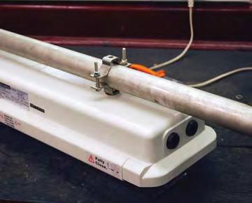

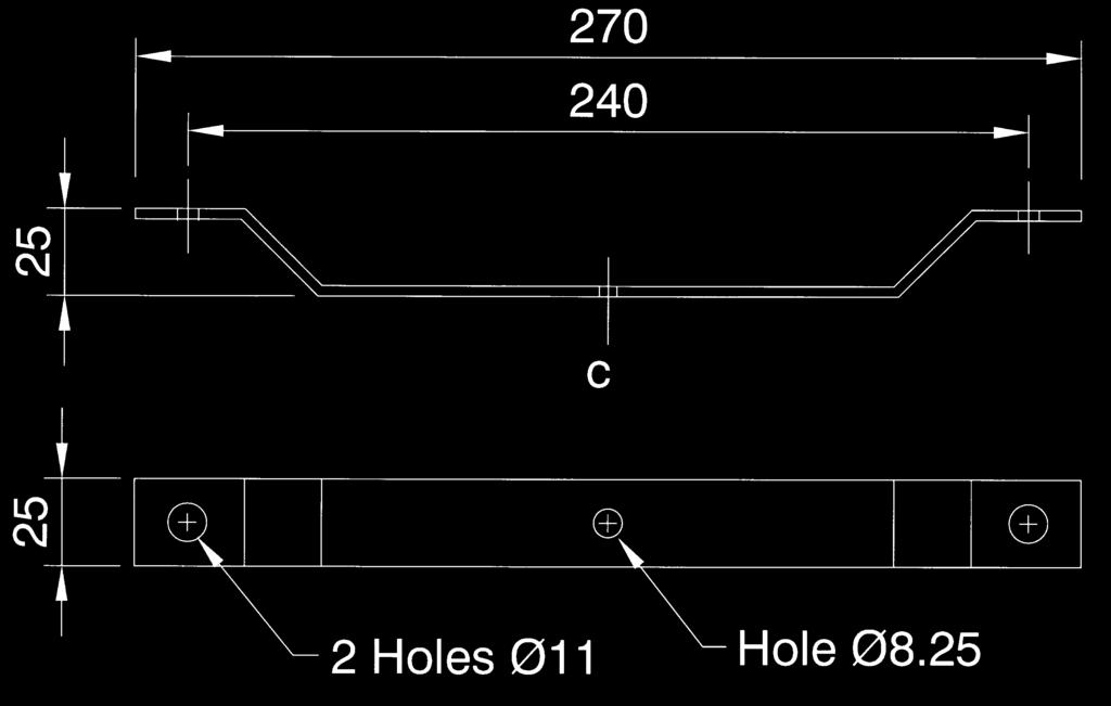
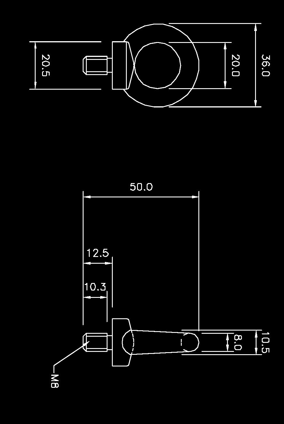

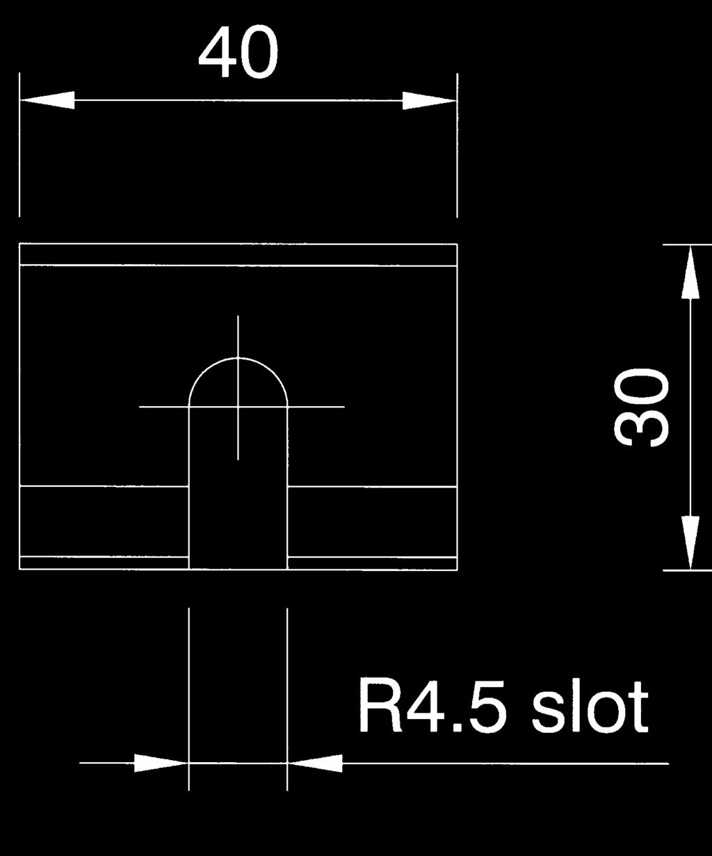
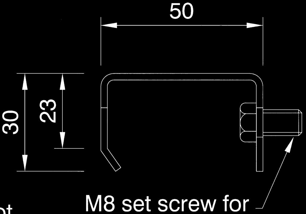
28 PROTECTA III 28 Pole Mounting Bracket Assembly Cat No. SPOL /100002/ Pole mounting bracket to suit pole diameter (38-42mm) SPOL (48-52mm) SPOL (58-62mm) SPOL Hook Type Ceiling Bracket Assembly Cat No. SPRO Ceiling Mounting Bracket Assembly Cat No. SPRO Eyelet Mounting Assembly Cat No. SPRO5-0005


 size A = 1100mm")


29 MOUNTING OPTIONS 29 Flush Mounting Wall Bracket Assembly Cat No. SPRO Note: All brackets are made from 316 Stainless Steel Wall Mounting Outreach Bracket Cat No. NPRO4-0007/0008/0012 Pole length A for use with the following: 1. 18W and 36W spigot entry body, size A = 250mm Cat No. NPRO W body c/w pole clamps (SPOL ), size A = 650mm Cat No. NPRO W body c/w pole clamps, (SPOL ) size A = 1100mm Cat No. NPRO Pole clamps for items 2 & 3 must be ordered separately, see SPOL W Spigot Entry Cat No. PRGE/218/BI/SE 36W Spigot Entry Cat No. PRGE/236/BI/SE
30 ACCLAIM Ex e RECESSIBLE 30 The Acclaim III is a recessed fluorescent specifically designed for use in solid or plank ceiling types. The luminaire is SOLAS B15 approved and suitable for use in offshore accommodation modules for both task and emergency lighting. To allow safe and easy maintenance Acclaim III features automatic lamp de-energisation upon opening. Emergency versions provide battery management, monitoring and self-test functions, this ensures safe and dependable battery back-up operation. Standard Specification Features Type of Protection Area Classification ATEX Classification Certificate Coding Enclosure Reflector/Geartray Entry Termination Installation Lampholder Control Gear Relamping Burning Position Ingress Protection Electrical Supply Battery Duration Emergency Output Ex e mb q (Increased safety Encapsulation Powder filling) Group II Category 2 GD Zone 1 and Zone 21 areas to EN and EN with installation to EN EC Type Examination Certificate Baseefa04ATEX0286 II 2 GD Ex e mb q IIC T4 Tamb 45 C White polyester painted zinc coated steel body and frame. Silicone rubber gasket. Clear polycarbonate diffuser White polyester painted zinc coated steel 4 x 20mm holes, two at one end and two at the other end Quick release mains terminals - 3 core 4mm² max. conductor with looping and through wiring facility. 4 core 4mm² connectors on emergency). (6mm² terminations available - /SC option) Fixed side brackets with swing out arms, with provision for drop rod mounting G13 (Bi pin) High Frequency Via front cover, secured by pan head slotted screws Horizontal IP65 to EN V - 254V 50/60Hz 220V - 300V dc (non-emergency only) Internal Ni-Cd (6V) 90 minutes to EN % of one lamp (18W) 25% of one lamp (36W) Automatic lamp de-energisation on opening Battery management, monitoring and automatic self test Resistant to voltage fluctuations Local switching arrangement as standard Ingress protection to IP65 dc operation (non emergency) B15 SOLAS fire rating - appropriate insulation is required over the luminaire Emergency inhibition and power off re-start End of life (EOL) protection to IEC (with EOL I and EOL II functionality) International Approvals ATEX and CSA IECEx Compliant
31 ATEX CATEGORY 2 ZONE 1 & 21 APPLICATIONS 31 Std. Cat No. Wattage Lamp TClass T C(Dust) Ambient C Weight ACLE/218/BI 2x18W T8 T to kg ACLE/236/BI 2x36W T8 T to kg ACLE/218/BI/EM 2x18W T8 T to kg ACLE/236/BI/EM 2x36W T8 T to kg Options - Suffix to Catalogue No. /120 Specific voltage (110/130) /25 25mm cable entries /PD /PC Prismatic diffuser Solid plank ceiling /RI Remote emergency inhibition facility (external switch ordered separately) /SC Screwed connection terminal block (up to 6mm 2 conductors) /3P 3 phase termination facility (not available if through wiring required) /EL Extra live termination facility (compatible with 4 core switched emergency circuits) /NST /HEO High frequency - non self test ballast High emergency output, 45% of one lamp (36W version only) /3H 3 hour battery duration* /LG Low glare louvre /IEC Supplied with IECEx certification label * 18W = 30% of one lamp, 36W = 25% of one lamp Note: Ceiling type must be stated at time of enquiry/order Standard Clear Diffuser Single screw height adjustment Prismatic Diffuser (/PD) Adjust to ensure ceiling integrity Low Glare Louvre (/LG) Product design and specifications are subject to change without notice, please check the Chalmit website for latest specifications.
32 M300 Plank Ceiling Types 32 Standard Model sided 25mm skirt 18W W W W Typical aperture: 35 Tile length x 800mm (18W) Tile length x 1315mm (36W) Front cover depth 25mm Front view of recessed luminaire W W W W W W Ø x 20mm cable entry holes at each end, complete with 3 blanking plugs & 1 transit plug Front cover depth 25mm Rear view of recessed luminaire
33 Solid Ceiling Types 33 swing out arms /PC Model W W Typical aperture: 300mm x 740/750mm (18W) 300mm x 1355/1356mm (36W) Front cover depth 10mm Front view of recessed luminaire W W W W W W W W Ø x 20mm cable entry holes at each end, complete with 3 blanking plugs & 1 transit plug Front cover depth 10mm Rear view of recessed luminaire

34 CURIE ELITE Ex e RECESSIBLE 34 The Curie Elite is a recessed fluorescent specifically designed for use in solid or modular ceiling types. The luminaire is SOLAS B15 approved and suitable for use in offshore accommodation modules for both task and emergency lighting. To allow safe and easy maintenance Curie features automatic lamp de-energisation upon opening. Emergency versions provide battery management, monitoring and self-test functions, this ensures safe and dependable battery back-up operation. Standard Specification Features Type of Protection ATEX Classification Area Classification Certificate Coding Enclosure Reflector/Geartray Entry Termination Installation Lampholder Control Gear Relamping Burning Position Ingress Protection Electrical Supply Battery Battery Duration Emergency Output Ex e mb q (Increased safety Encapsulation Powder filling) Dust protected enclosure Group II Category 2 GD Zone 1 and Zone 21 areas to EN and EN with installation to EN EC Type Examination Certificate Baseefa02ATEX0117X II 2 GD Ex e mb q IIC T4 Tamb 40 C White polyester painted zinc coated steel body and aluminium frame. EPDM rubber gasket. Prismatic polycarbonate diffuser. White polyester painted zinc coated steel 3 x 20mm diameter holes for cable entries, mounted on the top two at one end and one at the other end 3 core 4mm² max. conductor with looping and through wiring 16A rating. 4 core 4mm² connectors on emergency). (6mm² terminations available - /SC option) Side brackets with adjustable arms (solid ceilings) Rotating cams (Exposed T and Spring T ceilings). There is also a provision for drop rod mounting G13 (Bi-pin) High Frequency Access via front cover secured by screws Horizontal IP65 to EN : V - 254V 50/60Hz, and 220V - 300V dc (non-emergency only) Internal Ni-Cd (6V) 90 minutes to EN % of one lamp (18W) 25% of one lamp (36W) B15 SOLAS fire rating - appropriate insulation is required over the luminaire Battery management monitoring & automatic self test Simple and easy access via front cover for lamp replacement and maintenance Suspended gear tray for ease of maintenance Automatic lamp de-energisation on opening Electronic control gear gives 50/60Hz operation, high power factor correction and regulation of lamp output dc operation (non emergency) Local switching arrangement as standard End of life (EOL) protection to IEC (with EOL I and EOL II functionality) International Approvals ATEX and CSA IECEx Compliant

35 ATEX CATEGORY 2 ZONE 1 & 21 APPLICATIONS 35 Std. Cat No. Wattage Lamp TClass T C (Dust) Ambient C Weight CUEE/218/BI* 2x18W T8 T to kg CUEE/418/BI 4x18W T8 T to kg CUEE/236/BI* 2x36W T8 T to kg CUEE/436/BI 4x36W T8 T to kg CUEE/218/BI/EM* 2x18W T8 T to kg CUEE/418/BI/EM 4x18W T8 T to kg CUEE/236/BI/EM* 2x36W T8 T to kg CUEE/436/BI/EM 4x36W T8 T to kg * Only available in 600 x 600mm and 600 x 1200mm body styles. The standard Curie Elite is supplied with a 3mm clear outer panel & prismatic diffuser. Note: Modular ceiling types require the /MET or /MST suffix. Ceiling type must be stated at time of enquiry/order Options - Suffix to Catalogue No. /MET Modular Exposed T ceiling /LG Low glare louvre /MST /120 Modular Spring T ceiling Specific voltage (110/120) /NST High frequency non-self testing ballast (recommended for sleeping quarters) /25 25mm cable entries /2L 2 lamp emergency mode /SC Screwed connection terminal block (up to 6mm 2 conductors) /HEO High emergency output 90 minute duration (36W only) /EL Extra live termination facility (to match emergency circuit) /3H 3 hour battery duration* * 18W = 30% of one lamp, 36W = 25% of one lamp /LG - Low glare louvre Product design and specifications are subject to change without notice, please check the Chalmit website for latest specifications.
36 CEILING TYPE OPTIONS 36 CAM E Front View Rear View View of Exposed T Ceiling with recessed luminaire, typical 600mm x 600mm tile grid mounting system (/MET). CAM CAM D Front View Rear View View of Spring T Ceiling with recessed luminaire, typical 600mm x 600mm tile grid mounting system (/MST). Adjustable side arms Hook down mounting brackets Hook up mounting brackets View of Solid Ceiling with recessed luminaire.
37 DIMENSIONS 37 Spring T bracket 4 holes Ø7.5 for drop mounting supplied plugged. Dimensions in millimetres W W W W X Sectional View W x W x x 21mm holes for cable entry supplied with 2 Ex blanking plugs & 1 transit plug. Exposed T bracket X Sectional View 44 Adjustable cams for mounting on T grid. Exposed T Ceiling (/MET) dimensions. Dimensions in millimetres Spring T bracket W W W W X Sectional View 4 Holes Ø7.8 18W W x 21mm holes for cable entry supplied with 2 Ex blanking plugs & 1 transit plug W W Exposed T bracket X Sectional View 4 Rotating mounting cams for mounting on T grid supports Spring T Ceiling (/MST) dimensions. 4 Holes Ø7.8 Dimensions in millimetres W W W W NOM X Sectional View x 21mm holes for cable entry supplied with 2 Ex blanking plugs & 1 transit plug. 18W W W W X Sectional View Overall height (including cover) 144mm Overall height (excluding cover) 138.5mm Solid Ceiling dimensions.


38 LOMOND Ex d FLUORESCENT 38 The Lomond is a rugged, flameproof T8 fluorescent luminaire. It features an integrated mounting channel for universal installation. The aluminium and glass construction make the Lomond highly resistant to aggressive chemical agents. The luminaire is available in single and twin lamp versions including an eight watt version for over door emergency exit marking. Standard Specification Features Type of Protection ATEX Classification Area Classification Certificate Coding Enclosure Reflector/Geartray Entry Termination Installation Control Gear Relamping Burning Position Ingress Protection Electrical Supply Emergency Duration Ex d (flameproof), Ex dm (flameproof encapsulation) emergency version Group II Category 2 GD Zone 1 and 21 areas to EN and EN with installation to EN EC Type Examination Certificate SIRA05ATEX1299X II 2 GD Ex d IIC (8W & 18W) II 2 GD Ex d IIB (36W) Aluminium alloy LM6 to BS 1490 (AC44100) Borosilicate glass overtube, painted steel reflector 2 x M20 cable entries 3 core 4mm² max. conductor with looping 4 core 4mm² max connectors on emergency Via steel support rail High Frequency Two socket head screws and tapered spigotted flamepath Universal Ingress protection to IP66, IP67 and IP68 Non Emergency: 120V - 254V 50/60Hz (18W) 110V - 130V 50/60Hz (36W - /120) 220V - 254V 50/60Hz (36W, 58W) Emergency: 220V - 254V 50/60Hz (18W, 36W, 58W) 110V - 130V 50/60Hz (18W, 36W - /120) 3 hours Quick lamp start, flicker free High frequency electronic control gear Cool running improves T-rating Standard support channel allows for multiple fixing centres and options Suitable for high ambient areas Optional Exit Sign Kit for Emergency Escape Route Lighting International Approvals ATEX and GOST
39 ATEX CATEGORY 2 ZONE 1 & 21 APPLICATIONS 39 Std. Cat No. Wattage Lamp TClass T C (Dust) Ambient C Weight LOMD/108/BI 1x8W T5 T to kg LOMD/208/BI 2x8W T5 T to kg LOMD/218/BI 2x18W T8 T to kg LOMD/136/BI 1x36W T8 T to +53 T8 T to kg LOMD/236/BI 2x36W T8 T to +53 T8 T to kg LOMD/158/BI 1x58W T8 T to +49 T8 T to kg LOMD/258/BI 2x58W T8 T to +49 T8 T to kg LOMD/108/BI/EM 1x8W T5 T to kg LOMD/218/BI/EM 2x18W T8 T to kg LOMD/236/BI/EM 2x36W T8 T to +52 T8 T to kg LOMD/258/BI/EM 2x58W T8 T to kg Options - Suffix to Catalogue No. /M25 /SR M25 cable entries Stainless steel support rail /IIC Suitable for IIC gas areas (8W and 18W only) /NM /Non maintained (1x8W only) / V supply 916 for 18W, 1516 for 36W, 1816 for 58W Lampglass assembly Required for removal of Lampglass assembly Ballast housing External earth 8W with hanging exit sign Accessories Should be ordered separately Catalogue Order Code For details of accessories please see page 40 and 41 Product design and specifications are subject to change without notice, please check the Chalmit website for latest specifications.


 SPOL4-100004 (48-52mm)")
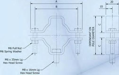
40 LOMOND Ex d FLUORESCENT 40 Ceiling Mounting Bracket Assembly Cat No. SLOMD Wall Mounting Bracket Assembly Cat No. SLOMD Pole Mounting Bracket Assembly Cat No. SPOL /100005/ Pole mounting bracket to suit pole diameter (38-42mm) SPOL (48-52mm) SPOL (58-62mm) SPOL

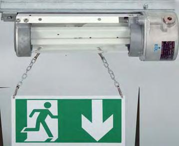

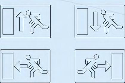
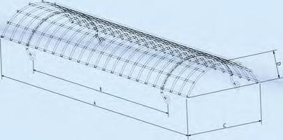
41 ATEX CATEGORY 2 ZONE 1 & 21 APPLICATIONS 41 Wire Guard Cat No. SLOMD /000009/ Hanging Exit Sign Cat No. SPATE-00005/00006/00007/00008/00009 Self Adhesive Exit Sign Kit Cat No. SPATE Up Exit sign Down Exit sign Left Exit sign Right Exit sign


42 EVOLUTION II 42 PHOTOMETRIC EXCELLENCE Benefits of Asymmetric Design Asymmetric reflector design uses an aiming angle from 0 to a maximum of 20 compared to a typical 45 angle for Symmetric floodlights. This has several benefits: Increased Photometric Efficiency - Higher lighting levels due to better utilisation of light Increased Energy Efficiency - Fewer floodlights to meet required lighting levels = reduced energy consumption Reduced glare & Light Pollution - Lower cut off angle Light where you need it Better Uniformity of light Asymmetric Reflector Symmetric Reflector Light cut-off angle Light cut-off angle Aiming angle <10 Aiming angle = 45 An asymmetric reflector allows the light beam to be both thrown forward a long distance and also light the area below the pole or mounting location is effectively lit. This efficient lighting profile gives lower glare and light pollution making it ideal for hazardous area applications including: Environmentally sensitive areas Energy efficient lighting schemes Tank Farms Security and Perimeter Lighting General task area lighting


43 Evolution Range KEY FEATURES 43 Easy Installation and Low Maintenance Chalmit Lighting luminaires are designed to ensure that they are simple to install and easy to maintain: Reduction in maintenance time Significantly reduce the overall site maintenance costs The Evolution range embodies this design philosophy. With its single bolt opening, the Evolution ensures easy access to lamp and control gear. Inspection and maintenance of the flamepaths is not required as they not are exposed. Instead, the unique design locates these within the IP67 sealed area of the control gear. In this respect, the Evolution can effectively be classed as maintenance free. Simple Re-lamping Complete in Under Three Minutes 1 2 Access to control gear and re-lamping by use of a single retained socket head cap screw Complete access is afforded by opening the gear cover. The mains terminal block and voltage tappings can be clearly seen and are readily accessible 3 4 The lamp enclosure is easily removed by disconnecting the lamp supply cables and rotating the housing to disengaging from the locating spigots The lamp housing can then be withdrawn to allow removal and/or inspection of the flamepath. With this done the lamp housing can be inserted back into the enclosure and located on the spigots and the cables connected. No Exposed Flamepath = No Flamepath Maintenance Routine

44 EVOLUTION II 44 Ex d e ASYMMETRIC FLOODLIGHT Optional PTFE Coating Recommended maximum aiming angle 20 from horizontal plane The Evolution II is a photometrically advanced floodlight that combines Ex de protection with optimised utilisation of light through its asymmetric design. The Evolution concept has no exposed flamepaths making the luminaire effectively maintenance free. Access to the lamp and terminal chamber is achieved by the unscrewing of a single captive bolt Standard Specification Features Type of Protection ATEX Classification Area Classification Certificate Coding Enclosure Reflector Entry Termination Installation Windage Control Gear Relamping Burning Position Ingress Protection Electrical Supply Ex d e (Flameproof, Increased Safety) Dust protected enclosure Group II Category 2 GD Zone 1 and Zone 21 areas to EN and EN with installation to EN Gas Groups IIA and IIB EC Type Examination Certificate Baseefa04ATEX0155 II 2 GD Ex d e IIB Refer to table for T rating and Ambient Aluminium alloy LM6 to BS 1490 (AC44100) All fastenings A4 stainless steel Toughened glass window Asymmetric beam, high purity anodised aluminium 2 x M20 cable entries 3 core 6mm² max. conductor with looping Stirrup mounting bracket with aiming quadrant 0.112m² Internal copper/iron with PFC correction capacitor and timed ignitor Access via hinged end cover on release of single screw Universal for HID, +/-45 on horizontal plain for Tungsten-Halogen lamps IP66/67 to EN , 230, 240, 254V 50Hz HPS & Metal Halide 24V - 254V Linear Tungsten-Halogen, 110V - 254V Single ended Tungsten-Halogen Installation in gas groups IIA and IIB Easy and quick access for maintenance Simple, rapid lamp replacement and flamepath inspection Reduced maintenance due to no exposed flamepath Exceptional photometric efficiency with reduced glare Timed ignitor supplied as standard International Approvals ATEX, GB (China) and GOST IECEx Compliant
 T C (Dust) Ambient C Weight EV2D/150/MS 150W HPS and Metal Halide E40 T4 T3 130 175-20 to +40-20 to +55 28.")
45 ATEX CATEGORY 2 ZONE 1 & 21 APPLICATIONS 45 Std. Cat No. Wattage Lamp Lampholder T Class (Gas) T C (Dust) Ambient C Weight EV2D/150/MS 150W HPS and Metal Halide E40 T4 T to to kg EV2D/250/MS 250W HPS and Metal Halide E40 T4 T to to kg EV2D/400/MS 400W HPS and Metal Halide E40 T to kg EV2D/600/HS* 600W HPS E40 T to kg EV2D/500/TH 500W Single Ended T/Halogen E40 T to kg EV2D/500/TL 500W Linear T/Halogen R7s T to kg *Ignitor only fitted. Remote gear box required (see Universal Box - page 66). Note: Please specify voltage at time of enquiry/order Options - Suffix to Catalogue No. / V - 130V (Weight increase of +10kg) /P PTFE coating /60 60Hz /PE Pendant mounted / V 60Hz /N Narrow beam option /M25 M25 cable entries /IEC Supplied with IECEx certification label NOTE: 120V version utilises deeper end cover (as shown above) Accessories Should be ordered separately Catalogue Order Code For details of accessories please see page 50 and 51 Product design and specifications are subject to change without notice, please check the Chalmit website for latest specifications.


46 EVOLUTION Ex d e FLOODLIGHT 46 The Evolution is a highly efficient floodlight that combines Ex de protection with optimised utilisation of light through advanced reflector design. The Evolution concept has no exposed flamepaths making the luminaire effectively maintenance free. Access to the lamp and terminal chamber is achieved by the unscrewing of a single captive bolt. The Evolution is suitable for use in IIC gas environments. Ex d e PENDANT HIGH BAY The Pendant version has simple mounting points and is designed for use in high bay applications. Standard Specification Features Type of Protection ATEX Classification Area Classification Certificate Coding Enclosure Reflector Entry Termination Installation Windage Control Gear Relamping Burning Position Ingress Protection Electrical Supply Ex d e (Flameproof, Increased Safety) Dust protected enclosure Group II Category 2 GD Zone 1 and Zone 21 areas to EN and EN with installation to EN Gas Groups IIA, IIB and IIC EC Type Examination Certificate BAS98ATEX2373 II 2 GD Ex d e IIC Refer to table for T rating and Ambient Aluminium alloy LM6 to BS 1490 (AC44100) All fastenings A4 stainless steel Toughened glass window Wide beam, high purity anodised aluminium 2 x M20 cable entries 3 core 6mm² max. conductor with looping Stirrup mounting bracket with aiming quadrant 0.159m² / 0.173m² (120V version) Internal copper/iron with PFC correction capacitor and timed ignitor Access via hinged end cover on release of single screw Universal for HID, +/-45 on horizontal plain for Tungsten-Halogen lamps IP66/67 to EN , 230, 240, 254V 50Hz HPS & Metal Halide 24V - 254V ac/dc linear Tungsten-Halogen, 110V - 254V single ended Tungsten-Halogen Installation in gas groups IIA, IIB and IIC Easy and quick access for maintenance Simple, rapid lamp replacement and flamepath inspection Reduced maintenance due to no exposed flamepath Exceptional photometric efficiency Effective light distribution for many applications Timed ignitor supplied as standard International Approvals ATEX, GOST, CSA, CEPEL and TIS IECEx Compliant
47 ATEX CATEGORY 2 ZONE 1 & 21 APPLICATIONS 47 Std. Cat No. Wattage Lamp Lampholder T Class (Gas) T C (Dust) Ambient C Weight EVOD/150/MS 150W HPS and Metal Halide E40 T4 T kg EVOD/250/MS 250W HPS and Metal Halide E40 T4 T kg EVOD/400/MS 400W HPS and Metal Halide E40 T kg EVOD/600/HS* 600W HPS E40 T kg EVOD/500/TH 500W Single Ended T/Halogen E40 T kg EVOD/500/TL 500W Linear T/Halogen R7s T kg *Ignitor only fitted. Remote gear box required (see Universal Box - page 66). For Pendant substitute EVPD for EVOD. Note: Please specify voltage at time of enquiry/order Options - Suffix to Catalogue No. / V (Weight increase of +12kg) (Extended end cover) /60 60Hz /M25 M25 cable entries /N Narrow beam reflector /M Medium beam reflector /P PTFE coating /LT Low temperature version -50 C (Gas groups IIA and IIB only) /IEC Supplied with IECEx certification label (Low temperature version) NOTE: 120V version utilises deeper end cover (as shown above) Accessories Should be ordered separately Catalogue Order Code For details of accessories please see page 50 and 51 Product design and specifications are subject to change without notice, please check the Chalmit website for latest specifications.

48 EVOLUTION JUNIOR Ex d e FLOODLIGHT 48 The Evolution Junior is a lightweight and portable version of the advanced Evolution floodlight. It features the same single bolt access and has a range of floor and tripod stands for a variety of temporary applications. Standard Specification Features Type of Protection ATEX Classification Area Classification Certificate Coding Enclosure Reflector Entry Termination Installation Windage Control Gear Relamping Burning Position Ingress Protection Electrical Supply Ex d e (Flameproof, Increased Safety) Group II Category 2 G Zone 1 and Zone 2 areas to EN with installation to EN Gas Groups IIA, IIB and IIC EC Type Examination Certificate BAS99ATEX2228 II 2 G Ex d e IIC Refer to table for T rating and Ambient Aluminium alloy LM6 to BS 1490 (AC44100) All fastenings A4 stainless steel Toughened glass window Wide beam, high purity anodised aluminium 2 x M20 cable entries 3 core 6mm² max. conductor with looping Stirrup mounting bracket 0.094m² Internal copper/iron with PFC correction capacitor Access via hinged end cover on release of single screw Universal for HID, +/-45 on horizontal axis for Tungsten-Halogen Lamps IP66/67 to EN , 230, 240, 254V 50Hz (HID) 24V(ac/dc)-250V (dependant on voltage) Installation in gas groups IIA, IIB and IIC Easy and quick access for maintenance Simple, rapid lamp replacement and flamepath inspection Exceptional photometric efficiency Available with secondary protective glass for shot blasting applications International Approvals ATEX, GOST CEPEL and TIS
49 ATEX CATEGORY 2 ZONE 1 APPLICATIONS 49 Std. Cat No. Wattage Lamp Lampholder T Class Ambient C Weight EVJD/070/MS 70W HPS and Metal Halide E27 T kg T kg 150W Tungsten-Halogen R7s T kg 200W Tungsten-Halogen R7s T kg EVJD/300/TL 250W Tungsten-Halogen R7s T kg T kg 300W Tungsten-Halogen R7s T kg EVJD/150/TL/24 150W 24V Tungsten-Halogen R7s T kg Secondary Glass Shield Cat Nos. 150W Tungsten-Halogen R7s T kg EVJD/300/TL/GS 200W Tungsten-Halogen R7s T kg 200W Tungsten-Halogen R7s T kg 250W Tungsten-Halogen R7s T kg EVJD/300/TL/24/GS 150W 24V Tungsten-Halogen R7s T kg Note: Please specify voltage at time of enquiry/order Options - Suffix to Catalogue No. /60 /M25 /P /Y /LT 60Hz M25 cable entries PTFE coating Yellow painted version (110V only) Low temperature version -50 C (IIA & IIB only) /FS /CG /CGP /GS Suitable for use with floor stand (floor stand should be ordered separately) Cable and Ex gland fitted (order cable separately - see accessories) Cable, Ex gland and 110V plug (cable should be ordered seperately) Secondary glass (factory fitted) Accessories Should be ordered separately Catalogue Order Code Pole mounting bracket assembly (48-70mm diameter poles) SEVJ Anti-glare shield SEVJ Wire guard SEVJ Floor stand assembly (to be ordered with floor stand version of floodlight) SEVJR-0001 Tripod stand assembly SEVJR-0002 Ratchet handles (2 off) for adjustable aiming SEVJR-0005 Cable (ordered per metre) E Product design and specifications are subject to change without notice, please check the Chalmit website for latest specifications.


50 EVOLUTION RANGE 50 Evolution II & Evolution Guards and Shields Evolution II Wire Guard Evolution Anti-Glare Shield Wire Guard Combined Anti-Glare Shield and Wire Guard SEV SEV SEV SEV Evolution Anti-Glare Shield Combined Anti-Glare Shield and Wire Guard Swing Jib Damper & Bracket Assembly Evolution only Damper assembly - SEV Bracket assembly - SEV


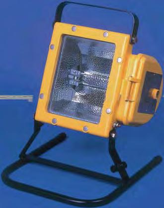
51 SERVICE & MOUNTING ACCESSORIES 51 Pole Mounting Bracket Assembly Cat No. SEV Retrofit Bracket Cat No. SEV Evolution Junior Mounting Accessories Cat No. SEVJR-0001/SEVJR-0002 Floor assembly SEVJR-0001 Tripod assembly SEVJR-0002
52 NEVIS Ex d e BULKHEAD 52 The Nevis bulkhead is designed for low profile applications. It can be mounted on walls, handrails and ceilings making it ideal for walkways or restricted height areas. The wide ambient temperature range makes the Nevis suitable for extreme environmental conditions. The Nevis has a side mounted increased safety terminal chamber. This eliminates the need for flameproof glands and allows for flush mounting with easy cable access. Standard Specification Features Type of Protection ATEX Classification Area Classification Certificate Coding Enclosure Internal Reflector Entry Termination Installation Control Gear Relamping Burning Position Ingress Protection Electrical Supply Ex d e (Flameproof, Increased Safety) Group II Category 2 GD Zone 1 and Zone 21 areas to EN and EN with installation to EN Gas Groups IIA and IIB EC Type Examination Certificate Baseefa08ATEX0178 II Ex d e IIB Refer to table for T rating and Ambient Aluminium alloy LM6 to BS 1490 (AC44100) All fastenings A4 stainless steel Toughened glass dome cover High purity anodised aluminium 2 x M20 cable entries 3 core 6mm² max. conductor with looping Flush mounting bracket Internal copper/iron with PFC correction capacitor Access via hinged front glass cover assembly Universal IP66/67 to EN , 230, 240, 254V 50Hz - 70 HPS/Metal Halide 220, 230, 240V 50Hz - 80 and 125W MBF/U 250V Max GLS/MBTF 240V - CF V QL Installation to gas groups IIA and IIB Ex e cable entries and looping as standard Hinged front cover Captive cover screws High ingress protection Internal reflector options Low temperature applications to -55 C Compact construction International Approvals ATEX and GOST IECEx Compliant
53 ATEX CATEGORY 2 ZONE 1 & 21 APPLICATIONS 53 Std. Cat No. Wattage Lamp TClass T C (Dust) Ambient C Weight NEVD/050/HS 50W HPS T to kg NEVD/070/MS 70W HPS and Metal Halide T to kg NEVD/080/MV 80W Mercury Vapour T to kg NEVD/125/MV 125W Mercury Vapour T to kg NEVD/200/GL 200W GLS T to kg NEVD/118/CF 18W Compact Fluorescent T to kg NEVD/126/CF 26W Compact Fluorescent T to kg NEVD/160/MB 160W MBTF T to kg NEVD/055/QL 55W QL T to kg Note: Please specify voltage at time of enquiry/order Options - Suffix to Catalogue No. /120 /60 /M25 120V, 50/70W HPS, 70W Metal Halide Compact fluorescent and QL lamp 60Hz M25 cable entries /P /TI /NC PTFE coating Timed ignitor No power factor correction capacitors fitted Accessories Should be ordered separately Pole mounting bracket assembly (38-50mm diameter poles) Wire guard Catalogue Order Code SNEV SNEV Hand rail mounting bracket assembly Product design and specifications are subject to change without notice, please check the Chalmit website for latest specifications. SNEV4-0003


 All fastenings A4")
54 216 Ex d e WELL-GLASS 54 The 216 with an external reflector The 216 is compact wellglass ideal for areas where efficient localised lighting is required. The luminaire has a side mounted increased safety terminal chamber eliminating the need for flameproof glands. The wide ambient temperature range makes the 216 suitable for extreme environmental conditions. The 216 with wire guard Standard Specification Features Type of Protection ATEX Classification Area Classification Certificate Coding Enclosure Reflector Entry Termination Installation Windage Control Gear Relamping Burning Position Ingress Protection Electrical Supply Ex d e (Flameproof, Increased safety) Group II Category 2 G Zone 1 and Zone 2 areas to EN with installation to EN Gas Groups IIA and IIB EC Type Examination Certificate BAS01ATEX2307 II 2 G Ex d e IIB Refer to table for T rating and Ambient Aluminium alloy LM6 to BS 1490 (AC44100) All fastenings A4 stainless steel Toughened glass dome globe High purity anodised aluminium 2 x M20 cable entries 3 core 6mm² max. conductor with looping Flush mounting bracket 0.084m² Internal copper/iron with PFC correction capacitor Access via front glass cover assembly Universal IP66/67 to EN ,230,240,254V 50Hz (H.I.D) 250V max (GLS) 240V (CF) Installation to gas groups IIA and IIB Highly resistant to mechanical damage and corrosion Stainless steel fasteners Compact and efficient Ex e terminal chamber Compact fluorescents have 6 times the life of tungsten lamps and consume 80% less power. Anchor chain on glass cover assembly Suitable for use down to -50 C ambient International Approvals ATEX and GOST

55 ATEX CATEGORY 2 ZONE 1 APPLICATIONS 55 Std. Cat No. Wattage Lamp Lampholder T Class Ambient C Weight 216D/050/HS 50W HPS E27 T4-50 to kg 216D/070/HS 70W HPS E27 T4-50 to kg 216D/080/MV 80W Mercury Vapour E27 T4-20 to kg 216D/100/GL 100W GLS E27 T4-50 to kg 216D/200/GL 200W GLS E27 T3-50 to kg 216D/113/CF 1x10/13W 4-pin Compact Fluor G24q T6-50 to kg 216D/118/CF 1x18W 4-pin Compact Fluor G24q T5-50 to kg 216D/126/CF 1x26W 4-pin Compact Fluor G24q T5-50 to kg 216D/213/CF 2x10/13W 4-pin Compact Fluor G24q T5-50 to kg 216D/218/CF 2x18W 4-pin Compact Fluor G24q T5-50 to kg Note: Please specify voltage at time of enquiry/order Options - Suffix to Catalogue No. / /60 /M25 Specific voltage (110,120, 130 compact flourescent) 60Hz M25 cable entries /P /S /2P PTFE coating Stirrup mounting bracket 2 pin compact fluorescent version c/w switch start control gear (single lamp version only) Accessories Should be ordered separately Catalogue Order Code Pole mounting bracket assembly - stirrup mounting version only (48-60mm diameter poles) S Pole mounting bracket assembly c/w stirrup - retro fit for flush mounting bracket (48-60mm diameter poles) S Wire guard S External reflector S Product design and specifications are subject to change without notice, please check the Chalmit website for latest specifications.


56 238 Ex d e WELL-GLASS 56 The 238 with external reflector The 238 is a powerful and efficient wellglass that is designed for general purpose low and medium bay illumination. The luminaire has a side mounted increased safety terminal chamber eliminating the need for flameproof glands. The wide ambient temperature range makes the 238 suitable for extreme environmental conditions. The 238 with wire guard Standard Specification Features Type of Protection ATEX Classification Area Classification Certificate Coding Enclosure Internal Reflector Entry Termination Installation Windage Control Gear Relamping Burning Position Ingress Protection Electrical Supply Ex d e (Flameproof, Increased Safety), Ex td (Dust) Group II Category 2 GD Zone 1 and Zone 21 areas to EN and EN with installation to EN and Gas Groups IIA and IIB EC Type Examination Certificate BAS08ATEX0177 IEC Ex BAS II 2 GD Ex d e IIB Refer to table for T rating and Ambient Aluminium alloy LM6 to BS 1490 (AC44100) All fastenings A4 stainless steel Toughened glass dome globe High purity anodised aluminium 2 x M20 cable entries 3 core 6mm² max. conductor with looping Flush mounting bracket 0.138m² Internal copper/iron with PFC correction capacitor Access via front glass cover assembly Universal IP66/67 to EN , 230, 240, 254V 50Hz - 70, 150 & 250W HPS/Metal Halide 220, 230, 240V 50Hz - 80, 125, 250W MBF/U & 100W HPS 250V Max GLS/MBTF Installation to gas groups IIA and IIB Ex e cable entries and looping as standard Anchor chain on glass cover assembly High ingress protection External reflector (option) Low temperature applications to -50 C Compact construction International Approvals ATEX, GOST and CSA IECEx Compliant

57 ATEX CATEGORY 2 ZONE 1 APPLICATIONS 57 Std. Cat No. Wattage Lamp Lampholder TClass T C (Dust) Ambient C Weight 238D/070/HS 70W HPS E27 T to +60* 17.0kg 238D/100/HS 100W HPS E40 T to +60* 17.0kg 238D/150/MS 150W HPS and Metal Halide E40 T to kg 238D/250/HS 250W HPS and Metal Halide E40 T to +45* 20.0kg 238D/080/MV 80W Mercury Vapour E27 T to +60* 17.0kg 238D/125/MV 125W Mercury Vapour E27 T to kg 238D/250/MV 250W Mercury Vapour E40 T to +45* 19.5kg 238D/150/GL 150W GLS E27 T to +60* 15.5kg 238D/200/GL 200W GLS E27 T to kg 238D/300/GL 300W GLS E27 T to kg 238D/160/MB 160W MBTF E27 T to +50* 15.5kg 238D/085/QL 85W QL QL T to kg 238D/070/HS/T5 70W HPS E27 T to kg 238D/150/MS/T3 150W HPS and Metal Halide E40 T to +55* 18.0kg 238D/125/MV/T3 125W Mercury Vapour E27 T to +50* 17.0kg Note: Refer to installation leaflet for cable rating on models marked * The 250W luminaires have a 70 C cable rating at ambients of 30 C. Note: Please specify voltage at time of enquiry/order Options - Suffix to Catalogue No. / V QL only /P PTFE coating /60 /M25 /TI 60Hz M25 cable entries Timed ignitor /S /NC Stirrup mounting bracket No power factor correction capacitors fitted Accessories Should be ordered separately Catalogue Order Code Pole mounting bracket assembly - stirrup mounting version only (42-64mm diameter poles) S Wire guard S External reflector S Product design and specifications are subject to change without notice, please check the Chalmit website for latest specifications.


 All fastenings A4")
58 261 Ex d e WELL-GLASS 58 The 261 with external reflector The 261 is an efficient high wattage wellglass for general task area and highbay lighting. The luminaire has a side mounted increased safety terminal chamber eliminating the need for flameproof glands. The 261 is suitable for low temperature operation (-40 C) with high pressure sodium lamps. The 261 with wire guard Standard Specification Features Type of Protection ATEX Classification Area Classification Certificate Coding Enclosure Reflector Entry Termination Installation Windage Control Gear Relamping Burning Position Ingress Protection Electrical Supply Ex d e (Flameproof, Increased Safety) Group II Category 2 G Zone 1 and Zone 2 areas to EN with installation to EN Gas Groups IIA and IIB EC Type Examination Certificate BAS01ATEX2309 II 2 G Ex d e IIB Refer to table fort rating and Ambient Aluminium alloy LM6 to BS 1490 (AC44100) All fastenings A4 stainless steel Toughened glass dome globe High purity anodised aluminium 2 x M20 cable entries 3 core 6mm² max. conductor with looping Stirrup mounting bracket 0.197m² Internal copper/iron with PFC correction capacitor Access via front glass cover assembly Universal IP66/67 to EN , 230, 240, 254V 50Hz (HID) 110V - 240V ac/dc (GLS) Installation to gas groups IIA and IIB Ex e terminal chamber Stainless steel fasteners Anchor chain on glass cover assembly Low temperature applications to -40 C International Approvals ATEX and GOST IECEx Compliant

59 ATEX CATEGORY 2 ZONE 1 APPLICATIONS 59 Std. Cat No. Wattage Lamp TClass Ambient C Weight 261D/150/HS 150W HPS T4-40 to kg 261D/250/HS 250W HPS T4-40 to kg 261D/400/HS 400W HPS T4-40 to kg 261D/125/MV 125W Mercury Vapour T4-20 to kg 261D/250/MV 250W Mercury Vapour T4-20 to kg 261D/400/MV 400W Mercury Vapour T4-20 to kg 261D/250/MH 250W Metal Halide T4-40 to kg 261D/400/MH 400W Metal Halide T4-40 to kg 261D/500/GL Up to 500W GLS T4-40 to kg T3-40 to kg 261D/125/MV/F* 125W Mercury Vapour T4-40 to kg *F - Flush / Pendant Mounted Version. Note: When the external reflector is fitted with the flush/pendant version, the 'T' class and ambients stated above apply. When fitted to the stirrup mounted version the 'T' class changes to T3 with the ambient remaining the same. Note: Please specify voltage at time of enquiry/order Options - Suffix to Catalogue No. /P PTFE coating /60 60Hz /M25 M25 cable entries /TI Timed ignitor Accessories Should be ordered separately Catalogue Order Code Pole mounting bracket assembly (42-64mm diameter poles) S Wire guard S External reflector S Product design and specifications are subject to change without notice, please check the Chalmit website for latest specifications.

 Battery Box: Ex e m (Increased Safety Encapsulation) Group II Category 2 G Zone")
60 261E and EMERGENCY PROJECTOR Ex d Ex e PROTECTION The 261E provides focused safety critical lighting in emergency evacuation situations. It is designed to provide illumination during the launching of lifeboats to ensure the way is clear of hazards. Standard Specification Features Type of Protection ATEX Classification Area Classification Certificate Coding Enclosure Reflector Entry Termination Installation Windage Control Gear Relamping Burning Position Ingress Protection Electrical Supply Emergency Light Duration Luminaire: Ex d e (Flameproof Increased Safety) Battery Box: Ex e m (Increased Safety Encapsulation) Group II Category 2 G Zone 1 and Zone 2 areas to EN with installation to EN EC Type Examination Certificate BAS01ATEX2310 Battery Box: Baseefa03ATEX E: Ex d e IIB T4 723: Ex e m II T4 Aluminium alloy LM6 to BS 1490 (AC44100) All fastenings A4 stainless steel Toughened glass window Battery Box: Marine grade 316S31 stainless steel with silicone rubber gasket High purity anodised aluminium (narrow beam - single ended lamp) (wide beam - double ended lamp) 2 x M20 cable entries for mains supply and 1 x M25 cable entry for interconnection 3 core 6mm 2 max. conductor with looping for mains supply and 12 core 1.5mm² luminaire to battery box Luminaire: Stirrup mounting bracket Battery Box: Flat straps 0.096m² Electronic Access via front glass cover assembly Universal IP66/67 to EN , 230, 240, 250V 50Hz and 60Hz 90 minutes Installation to gas groups IIA and IIB Ex e terminal chamber Stainless steel fasteners, marine grade Anchor chain on glass cover assembly Increased safety battery Both wide and narrow beam versions available International Approvals ATEX
61 ATEX CATEGORY 2 ZONE 1 APPLICATIONS 61 Std. Cat No. Wattage Lamp Lampholder TClass Ambient C Weight Options - Suffix to Catalogue No. Flood Batery Box 261E/070/HS/EM* 70W HPS E27 T4-20 to kg 22.0kg 261E/070/MS/EM** 70W HPS or Metal Halide Rx7s T4-20 to kg 22.0kg Double Ended *Narrow beam **Wide beam Standard catalogue number incorporates both floodlight and box. Note: Please specify voltage at time of enquiry/order /M25 /P M25 cable entries (on 723 box) PTFE coating /NS Battery box without manual switching arrangement (automatic operation) Accessories Should be ordered separately Catalogue Order Code Pole mounting bracket assembly (42-64mm diameter poles) S Wire guard S Slave unit for operation on UPS 24dc 110/254ac Details on request Product design and specifications are subject to change without notice, please check the Chalmit website for latest specifications.
62 NexLED Ex e LED BULKHEAD 62 NexLED with Exit Sign kit The NexLED bulkhead utilises the latest LED technology to provide instant illumination. The NexLED requires no re-lamping making it virtually maintenance free and unaffected by low temperatures. This combination makes the NexLED ideal for extreme environmental applications. Coloured LED options are also available. NexLED with green LED s Standard Specification Features Type of Protection ATEX Classification Area Classification Certificate Coding Enclosure Reflector Entry Termination Installation Light Source Control Gear Burning Position Ingress Protection Electrical Supply Ex e mb (Increased Safety and Encapsulation) Group II Category 2 GD Zone 1 and Zone 21 area to EN and EN with installation to EN EC Type Examination Certificate Baseefa04ATEX0245 IEC Ex BAS II 2 GD Ex e mb IIC Refer to table for T rating and Ambient Aluminium alloy LM6 to BS 1490 (AC44100) with toughened glass and silicone gasket Brushed aluminium 2 x M20 cable entries 3 core 4mm² max conductor with looping Surface mounted, 4 mounting holes located outside of seal 1W light emitting diodes. Colour: white Electronic Universal IP66/67 to EN V AC (50/60Hz)/DC Installation to gas groups IIA, IIB and IIC Highly visible, instant light Easy to install and maintain Ultra long life, no relamping required Very low power consumption International Approvals ATEX and GOST IECEx Compliant
63 ATEX CATEGORY 2 ZONE 1 & 21 APPLICATIONS 63 Std. Cat No. Wattage Light Source TClass T C (Dust) Ambient C Weight NELE/201/LE 2W Light Emitting Diode T to kg NELE/801/LE 8W Light Emitting Diode T to kg Options - Suffix to Catalogue No. /RDE Red LED s /ADE Amber LED s /GDE Green LED s /IEC Supplied with IECEx certification label /BDE Blue LED s Accessories Should be ordered separately Catalogue Order Code Exit sign kit (supplied with - up, down, left and right labels*) * Other signage options available upon request, please contact technical sales (techsupport@chalmit.com) SNEL Product design and specifications are subject to change without notice, please check the Chalmit website for latest specifications.
64 NexLED E Ex e ib mb EMERGENCY 64 NexLED with Exit Sign kit The NexLED emergency provides emergency battery backup to ensure continued operation in the event of a power outage. The emergency version benefits from the same features as the standard NexLED and is available as a special low temperature version for operation down to -45 C. Coloured LED options are also available. NexLED with green LED s Standard Specification Features Type of Protection ATEX Classification Area Classification Certificate Coding Enclosure Reflector Entry Termination Installation Light Source Control Gear Burning Position Ingress Protection Battery Emergency Duration Electrical Supply Ex e ib mb (Increased Safety, Intrisically Safe Encapsulated) Dust protected enclosure Group II Category 2 GD Zone 1 and Zone 21 areas to EN and EN with installation to EN EC Type Examination Certificate Baseefa04ATEX0245 IEC Ex BAS II 2 GD Ex e ib mb IIC T4 Aluminium alloy LM6 to BS 1490 (AC44100) with toughened glass and silicone gasket Brushed aluminium 2 x M20 cable entries 4 core 4mm² max conductor with looping Surface mounted, 4 mounting holes located outside of seal 1W light emitting diodes. Colour: white Electronic Universal IP66/67 to EN Ni-Cd (6V) 8W version - 90 minutes 2W version - 3 hours V AC/DC Installation to gas groups IIA, IIB and IIC Highly visible, instant light Easy to install and maintain Ultra long life, no relamping required Very low power consumption 100% output in emergency mode (Up to 3 hours) Rechargable Ni-Cd batteries with charging indication Compatible with UPS systems International Approvals ATEX and GOST IECEx Compliant
65 ATEX CATEGORY 2 ZONE 1 & 21 APPLICATIONS 65 Std. Cat No. Wattage Light Source TClass T C (Dust) Ambient C Weight NELE/201/LE/EM 2W Light Emitting Diode T to kg NELE/801/LE/EM 8W Light Emitting Diode T to kg Options - Suffix to Catalogue No. /RDE Red LED s /ADE Amber LED s /GDE Green LED s /LT Low temperature -45 C to +55 C /BDE Blue LED s /IEC Supplied with IECEx certification label Accessories Should be ordered separately Catalogue Order Code Exit sign kit (supplied with - up, down, left and right labels*) * Other signage options available upon request, please contact technical sales (techsupport@chalmit.com) SNEL Product design and specifications are subject to change without notice, please check the Chalmit website for latest specifications.
66 UNIVERSAL BOX 66 Ex e CONTROL BOX The Universal is a lamp control and transformer box for use in Zone 1 and Zone 2 hazardous areas. It can be used as a control box for up to 600W HID lamp sources. The Universal box can also be specified as a 120V transformer box up to 1000VA. Standard Specification Features Type of Protection ATEX Classification Area Classification Certificate Coding Enclosure Entry Termination Installation Control Gear Operating Position Ingress Protection Electrical Supply Ex d e m (Increased Safety, Flameproof, Encapsulated) Dust protected enclosure Group II Category 2 GD Zone 1 and Zone 21 areas to EN and EN with installation to EN Gas Groups IIA, IIB and IIC EC Type Examination Certificate BAS01ATEX2270 II 2 GD Ex d e m IIC Rrefer to table for T rating and ambient Marine grade 316S31 stainless steel with silicone rubber gasket 3 x M20 cable entries 3 core 6mm² max. conductor with looping Base mounting straps Internal copper/iron and PFC correction capacitor as required Cable entries on lower end, if mounted vertically IP66/67 to EN V 50Hz - Control box version, 120V 50-60Hz - Transformer box version Installation to gas groups IIA, IIB and IIC Marine grade stainless steel construction Easy to install and maintain Hinged lid with three captive fixing screws Control gear easily accessed and can be replaced Thermal cut-outs fitted on ballast and transformer International Approvals ATEX
67 ATEX CATEGORY 2 ZONE 1 & 21 APPLICATIONS 67 Std. Cat No. Wattage Lamp TClass T C (Dust) Ambient C Weight UNIE/150/HS 150W HPS/Metal Halide UNIE/250/MS 250W HPS/Metal Halide T to +45 T to +55 T to +45 T to kg 11.0kg UNIE/400/MS 400W HPS/Metal Halide T to kg UNIE/600/HS 600W HPS UNIE/500/TF* 500VA Transformer UNIE/1000/TF* 1000VA Transformer T to +45 T to +55 T to +35 T to +55 T to +35 T to kg 11.0kg 12.0kg *120 to 240V step up transformer boxes for fixed applications only. (Not portable). Options - Suffix to Catalogue No. /60 60Hz /MF Mains fuse (-20 C to +40 C only) /M25 M25 cable entries /3P 3 Phase termination Product design and specifications are subject to change without notice, please check the Chalmit website for latest specifications.
68 PROTECTA n 68 NORMAL and EMERGENCY LIGHTING Ex n FLUORESCENT The Protecta n utilises the proven strength and integrity as the Protecta III but is certified for use in Zone 2, Zone 21 and Zone 22 hazardous areas. The luminaire is recommended for use in areas where high levels of ingress protection is required Standard Specification Features Type of Protection ATEX Classification Area Classification Certificate Coding Enclosure Reflector Entry Termination Installation Control Gear Relamping Burning Position Ingress Protection Electrical Supply Battery Duration Emergency Output Ex na (Non-sparking) Group II Category 3 GD Zone 2 and Zone 22 areas to EN and EN with installation to EN Type Examination Certificate Baseefa08ATEX0227 IEC Certificate IECExBAS II 3 GD Ex na Refer to table for T rating and Ambient GRP body with polycarbonate cover and brass suspension points White polyester painted zinc coated steel 4 x M20 cable entries, 2 at each end 3 core 4mm² max. conductor with looping and through wiring 16A rating. 4 core 4mm² connectors on emergency). (6mm² terminations available - /SC option) Two M8 tapped brass inserts located on rear of body. High Frequency electronic ballast Emergency - electronic/inverter Quick release diffuser clamp and hinged cover Universal IP66/67 to EN V 50/60Hz Ni-Cd 6V (Emergency version only) 3 hours (Emergency version only) 18W 32% of one lamp 36W 14% of one lamp Easy access to suspended control gear tray High frequency control gear gives 50/60Hz operation, high power factor correction and regulation of lamp output dc operation (non-emergency only) Vibration tested to comply with Lloyds/ DNV DTS-01 deluge tested End of life (EOL) protection to IEC (with EOL I and EOL II functionality) Suitable for Zone 21 (Dust) areas Type Examination Certificate Baseefa08ATEX0228 Coding II 2D Ex td A21 T85 C International Approvals ATEX IECEx Compliant
69 ATEX CATEGORY 3 ZONE 2, 21 & 22 APPLICATIONS 69 Std. Cat No. Wattage TClass(Gas) T C (Dust) Ambient C Weight PR2N/218/BI 2x18W T to kg PR2N/136/BI 1x36W T to kg PR2N/236/BI 2x36W T to kg PR2N/218/BI/EM 2x18W T to kg PR2N/136/BI/EM 1x36W T to kg PR2N/236/BI/EM 2x36W T to kg Options - Suffix to Catalogue No. /120 Specific voltage (110V-130V) /3P Three phase termination /SC /M25 Screwed connection terminal block (up to 6mm² conductors) M25 cable entries /MF /IS /SE Mains fuse Isolation switch Spigot entry Accessories Should be ordered separately Pole mounting bracket assembly (38-42mm diameter poles) Pole mounting bracket assembly (48-52mm diameter poles) Pole mounting bracket assembly (58-62mm diameter poles) Hook type ceiling bracket assembly Ceiling bracket assembly Flush mounting wall bracket assembly Eyebolt mounting assembly Looping Kit (allows looping from both ends of luminaire) 18W wall mounting outreach bracket (use with SPOL ) Catalogue Order Code SPOL SPOL SPOL SPRO SPRO SPRO SPRO SPROT-0021 NPRO W wall mounting outreach bracket (use with SPOL ) Product design and specifications are subject to change without notice, please check the Chalmit website for latest specifications. NPRO4-0012
70 STERLING II Ex n FLUORESCENT 70 The Sterling II is a high quality but cost effective T8 fluorescent. Its lightweight and slimline construction make it simple to install and maintain. The luminaire features high frequency control gear with End of Life (EOL) protection. The Sterling II is available with single and twin lamp versions. Standard Specification Features Type of Protection ATEX Classification Area Classification Certificate Coding Enclosure Reflector Entry Termination Installation Control Gear Relamping Burning Position Ingress Protection Electrical Supply Ex na (Non-sparking) Group II Category 3 GD Zone 2 and Zone 22 areas to EN and EN with installation to EN Type Examination Certificate Sira 06ATEX4348X IEC Ex SIR X II 3 GD Ex na II T4 (refer to table for T rating and Ambient) GRP with polycarbonate diffuser and stainless steel retaining clips White polyester painted zinc coated steel 2 x 20mm diameter holes 4 core 4mm² max. conductor with through wiring 16A rating Two clearance holes for M8 fasteners located on rear of body, sealing washers provided High Frequency ballast Access via diffuser secured by quick release stainless steel clips Universal IP65 to EN V 50/60Hz (AC/DC) Robust polycarbonate diffuser with stainless steel clips as standard Through wiring as standard High frequency control gear gives 50/60Hz operation, high power factor correction and regulation of lamp output. Simple to install and maintain Lightweight and slim line construction End of life (EOL) protected International Approvals ATEX IECEx Compliant
71 ATEX CATEGORY 3 ZONE 2 & 22 APPLICATIONS 71 Std. Cat No. Wattage Voltage TClass T (Dust) Ambient C Weight ST2N/218/BI 2x18W 220V-254V T to kg ST2N/136/BI 1x36W 220V-254V T to kg ST2N/236/BI 2x36W 220V-254V T to kg ST2N/158/BI 1x58W 220V-254V T to kg ST2N/258/BI 2x58W 220V-254V T to kg Options - Suffix to Catalogue No. / V 50/60Hz AC /MF Mains fuse (Note: Upper ambient, limit of +30 C) B 2x8.2mm Dia. D 2x20mm Dia. cable entry clearance holes 1 each end. C A 2x18W 1x36W / 2x36W 1x58W / 2x58W A B C / / 172 D Accessories Should be ordered separately Pole mounting bracket assembly (38-42mm diameter poles) Pole mounting bracket assembly (48-52mm diameter poles) Pole mounting bracket assembly (58-62mm diameter poles) Catalogue Order Code SPOL SPOL SPOL Hook type ceiling bracket assembly S Ceiling bracket assembly S Flush mounting wall bracket assembly S W wall mounting outreach bracket (use with SPOL ) 36W wall mounting outreach bracket (use with SPOL ) 58W wall mounting outreach bracket (use with SPOL ) NPRO NPRO NPRO Product design and specifications are subject to change without notice, please check the Chalmit website for latest specifications.
72 STERLING II E 72 EMERGENCY LIGHTING Ex n FLUORESCENT The Sterling II Emergency features the same construction and EOL protected ballast as the standard product. In addition it also provides three hours of battery backup for emergency operation in the case of a power outage. Standard Specification Features Type of Protection ATEX Classification Area Classification Certificate Coding Enclosure Reflector Entry Termination Installation Control Gear Relamping Burning Position Ingress Protection Electrical Supply Battery Duration Emergency Output Ex na (Non-sparking) Group II Category 3 GD Zone 2 and Zone 22 areas to EN and EN with installation to EN EC Type Examination Certificate Sira 06ATEX4348X IEC Ex SIR X II 3 GD Ex na II T4 (refer to table for T rating and Ambient) GRP with polycarbonate diffuser and stainless steel retaining clips White polyester painted zinc coated steel 2 x 20mm diameter holes, 1 at each end 4 core 4mm² max. conductor with through wiring 16A rating Two clearance holes for M8 fasteners located on rear of body, sealing washers provided High Frequency ballast, electronic/inverter Access via front diffuser secured by quick release stainless steel clips Universal IP65 to EN V 50/60Hz Ni-Cd (6V) 3 hours 18W 32% of one lamp 36W 14% of one lamp 58W 9% of one lamp Polycarbonate diffuser Through wiring as standard High frequency control gear gives 50/60Hz operation, high power factor correction and regulation of lamp output. Long life nickel cadmium batteries Switchable mains supply for local operation LED charge indicator End of life (EOL) protected International Approvals ATEX IECEx Compliant
73 ATEX CATEGORY 3 ZONE 2 & 22 APPLICATIONS 73 Std. Cat No. Wattage Voltage TClass T (Dust) Ambient C Weight ST2N/218/BI/EM 2x18W 220V-254V T to kg ST2N/136/BI/EM 1x36W 220V-254V T to kg ST2N/236/BI/EM 2x36W 220V-254V T to kg ST2N/158/BI/EM 1x58W 220V-254V T to kg ST2N/258/BI/EM 2x58W 220V-254V T to kg Options - Suffix to Catalogue No. / V 50/60Hz AC (Note: Upper ambient, limit of +30 C) /NM Non maintained version (Single lamp version only) /MF Mains fuse /BMT Battery management test B 2x8.2mm Dia. D 2x20mm Dia. cable entry clearance holes 1 each end. C A 2x18W 1x36W / 2x36W 1x58W / 2x58W A B C / / 172 D Accessories Should be ordered separately Pole mounting bracket assembly (38-42mm diameter poles) Pole mounting bracket assembly (48-52mm diameter poles) Pole mounting bracket assembly (58-62mm diameter poles) Catalogue Order Code SPOL SPOL SPOL Hook type ceiling bracket assembly S Ceiling bracket assembly S Flush mounting wall bracket assembly S W wall mounting outreach bracket (use with SPOL ) 36W wall mounting outreach bracket (use with SPOL ) 58W wall mounting outreach bracket (use with SPOL ) NPRO NPRO NPRO Product design and specifications are subject to change without notice, please check the Chalmit website for latest specifications.
74 STERLING II S/S 74 STAINLESS STEEL Ex n FLUORESCENT The Sterling II is also available in a stainless steel body version. This incorporates the same design and protection features found in the GRP body Sterling II. The increased durability of its stainless steel construction makes this luminaire ideal for applications where there is a high risk of mechanical damage or exposure to chemical agents. Standard Specification Features Type of Protection ATEX Classification Area Classification Certificate Coding Enclosure Reflector Entry Termination Installation Control Gear Relamping Burning Position Ingress Protection Electrical Supply Ex na (Non-sparking) Group II Category 3 GD Zone 2 and Zone 22 areas to EN and EN with installation to EN Type Examination Certificate Sira 06ATEX4348X IEC Ex SIR X II 3 GD Ex na II T4 (refer to table for T rating and Ambient) Marine grade 316S31 stainless steel body with polycarbonate diffuser and stainless steel retaining clips White polyester painted zinc coated steel 3 x 20mm diameter holes, 2 at one end and 1 at the other end 3 core 4mm² max. conductor with looping and through wiring 16A rating Two clearance holes for M8 fasteners located on rear of body, sealing washers provided High Frequency ballast Access via front diffuser secured by quick release stainless steel clips Universal IP65 to EN V 50/60Hz (AC/DC) Marine grade stainless steel body and polycarbonate diffuser Mains connection terminals fixed to body Gear tray suspended and fitted with control gear for ease of maintenance High frequency control gear gives 50/60Hz operation, high power factor correction and regulation of lamp output. International Approvals ATEX IECEx Compliant
75 ATEX CATEGORY 2 ZONE 2 & 22 APPLICATIONS 75 Std. Cat No. Wattage TClass(Gas) T (Dust) Ambient C Weight SS2N/218/BI 2x18W T to kg SS2N/136/BI* 1x36W T to kg SS2N/236/BI 2x36W T to kg SS2N/158/BI* 1x58W T to kg SS2N/258/BI 2x58W T to kg * Single lamp versions are in twin bodies. Options - Suffix to Catalogue No. /120 /MF / V 50/60Hz AC (Note: Upper ambient, limit of +30 C) Mains fuse 3 x 25mm cable entries /CM /TE /EB Body c/w ceiling mounting brackets Threaded entry pads End mounting brackets attached B D 3x20mm Dia. cable entry clearance holes. 2x1 end 1x opposite. A C 2x18W 1x36W / 2x36W 1x58W / 2x58W A B C D Accessories Should be ordered separately Catalogue Order Code Pole mounting bracket assembly (38-42mm diameter poles) Pole mounting bracket assembly (48-52mm diameter poles) Pole mounting bracket assembly (58-62mm diameter poles) SPOL SPOL SPOL Hook type ceiling bracket assembly S Ceiling bracket assembly S Flush mounting wall bracket assembly S W wall mounting outreach bracket (use with SPOL ) 36W wall mounting outreach bracket (use with SPOL ) 58W wall mounting outreach bracket (use with SPOL ) NPRO NPRO NPRO Product design and specifications are subject to change without notice, please check the Chalmit website for latest specifications.
76 STERLING II E STAINLESS EMERGENCY 76 Ex n FLUORESCENT The Sterling II Emergency is also available in a stainless steel body version. This incorporates the same design and protection features found in the GRP body Sterling II. The increased durability of its stainless steel construction makes this luminaire ideal for applications where there is a high risk of mechanical damage or exposure to chemical agents. Standard Specification Features Type of Protection ATEX Classification Area Classification Certificate Coding Enclosure Reflector Entry Termination Installation Control Gear Relamping Burning Position Ingress Protection Electrical Supply Battery Duration Emergency Output Ex na (Non-sparking) Group II Category 3 GD Zone 2 and Zone 22 areas to EN and EN with installation to EN Type Examination Certificate Sira 06ATEX4348X IEC Ex SIR X II 3 GD Ex na II T4 (refer to table for T rating and Ambient) Marine grade 316S31 stainless steel body with polycarbonate diffuser and stainless steel retaining clips White polyester painted zinc coated steel 3 x 20mm diameter holes, 2 at one end and 1 at the other end 4 core 4mm² max. conductor with looping and through wiring 16A rating Two clearance holes for M8 fasteners located on rear of body, sealing washers provided High Frequency ballast, electronic inverter Access via front diffuser secured by quick release stainless steel clips Universal IP65 to EN V 50/60Hz 6V, 4Ah internal Ni-Cad 3 hours 18W 32% of one lamp, 36W 14% of one lamp, 58W 9% of one lamp Marine grade stainless steel body and polycarbonate diffuser Mains connection terminals fixed to body Gear tray suspended and fitted with control gear for ease of maintenance High frequency control gear gives 50/60Hz operation, high power factor correction and regulation of lamp output. Long life nickel cadmium batteries Switchable mains supply for local operation LED charge indicator International Approvals ATEX IECEx Compliant
77 ATEX CATEGORY 3 ZONE 2 & 22 APPLICATIONS 77 Std. Cat No. Wattage TClass(Gas) T (Dust) Ambient C Weight SS2N/218/BI/EM 2x18W T to kg SS2N/136/BI/EM* 1x36W T to kg SS2N/236/BI/EM 2x36W T to kg SS2N/158/BI/EM* 1x58W T to kg SS2N/258/BI/EM 2x58W T to kg * Single lamp versions are in twin bodies. Options - Suffix to Catalogue No. /120 /NM /MF / V 50/60Hz AC (Note: Upper ambient, limit of +30 C) Non-maintained (single lamp version only) Mains fuse 3 x 25mm cable entries /CM /TE /EB /BMT Body c/w ceiling mounting brackets Threaded entry pads End mounting brackets attached Battery management test B D 3x20mm Dia. cable entry clearance holes. 2x1 end 1x opposite. A C 2x18W 1x36W / 2x36W 1x58W / 2x58W A B C D Accessories Should be ordered separately Catalogue Order Code Pole mounting bracket assembly (38-42mm diameter poles) Pole mounting bracket assembly (48-52mm diameter poles) Pole mounting bracket assembly (58-62mm diameter poles) SPOL SPOL SPOL Hook type ceiling bracket assembly S Ceiling bracket assembly S Flush mounting wall bracket assembly S W wall mounting outreach bracket (use with SPOL ) 36W wall mounting outreach bracket (use with SPOL ) 58W wall mounting outreach bracket (use with SPOL ) NPRO NPRO NPRO Product design and specifications are subject to change without notice, please check the Chalmit website for latest specifications.
78 800 SERIES Ex n FLOODLIGHTS 78 The 854 with anti-glare shield Recommended maximum aiming angle 20 from horizontal plane The 800 series is a range of stainless steel asymmetrical floodlights. These floods are designed for optimum light output and efficiency to ensure the minimum number of luminaires is required. The 854 with wire guard Standard Specification Features Type of Protection ATEX Classification Area Classification Certificate Coding Enclosure Reflector Entry Termination Installation Windage Control Gear Relamping Burning Position Ingress Protection Electrical Supply Ex nr (Restricted Breathing) Group II Category 3 GD Zone 2 areas to EN and EN with installation to EN Type Examination Certificate BAS98ATEX3378 II 3 GD Ex nr II Refer to table overleaf for T rating and Ambient Marine grade 316S31 stainless steel body with toughened glass window, silicone rubber gasket Wide beam high purity anodised aluminium 2 x M20 cable entries 3 core 6mm² max. conductor with looping Stirrup mounting 0.052m² (844), 0.090m² (854), 0.107m² (864) Internal copper and iron ballast with ignitor and PFC correction capacitors Access via front glass cover assembly secured by quick release stainless steel clips Control gear must be level or below lamp position IP66/67 to EN , 230, 240, 254V 50Hz Photometrically superior asymmetric reflector Marine gradestainless steel body and toughened glass cover Quick release fasteners for ease of relamping and maintenance Suspended cover front Suitable for low temperature applications (-40 C) Standard control gear for use with IEC lamps International Approvals ATEX, GB (China), GOST and CEPEL
79 ATEX CATEGORY 3 ZONE 2 & 22 APPLICATIONS 79 Std. Cat No. Wattage Lamp Lampholder T Class Ambient C Weight 844N/070/MS 70W HPS/Metal Halide E C T3-40 to +50 T4-40 to kg 854N/100/HS 100W HPS E40 T4-40 to kg 854N/150/HS 150W HPS E40 T3-25 to +55 T4-40 to kg 854N/250/MS 250W HPS/Metal Halide E40 T4-25 to kg 854N/400/MS* 400W HPS/Metal Halide E40 T3-25 to kg 854N/500/TH 500W Single Ended T3-45 to +45 E40 T/Halogen T2-45 to kg 864N/250/MS 250W HPS/Metal Halide E40 T3-25 to kg 864N/400/MS 400W HPS/Metal Halide E40 T3-40 to +50 (HPS) -25 to +40 (MH) 21.0kg 100/120V Cat Nos. The following models are for 120V, 50Hz as standard: 864N/150/HS** 150W HPS E40 T3-40 to kg 864N/250/HS/120** 250W HPS E40 T3-40 to kg 864N/400/HS/120*** 400W HPS E40 T3-40 to kg * Ignitor only fitted within floodlight. Remote gear box required (see Universal Box). ** c/w IEC control gear 110/120V supply. *** Supplied with remote transformer box for 110/120V supply. (Control gear fitted for IEC lamps). Options - Suffix to Catalogue No. All control gear fitted for use with European lamps (IEC). /60 /M25 /N /TI /WA /TAP/CSA 60Hz M25 cable entries Narrow beam reflector Timed cut out ignitor Suitable for wire guard or anti-glare shield Quad tapped ballast (120, 208, 240, 277V) (Internal control gear for NEC lamps only CSA certificate - non ATEX) Accessories Should be ordered separately Catalogue Order Code Pole mounting bracket assembly (50-100mm diameter poles) S Pole mounting bracket assembly - 854/864 (48-70mm diameter poles) S Spigot top mounting bracket assembly - 854/864 (70-82mm diameter poles) S Wire guard (requires WA suffix when ordering) S Wire guard (requires WA suffix when ordering) S Wire guard (requires WA suffix when ordering) S Anti-glare shield (requires WA suffix when ordering) S Anti-glare shield (requires WA suffix when ordering) S Anti-glare shield (requires WA suffix when ordering) S Product design and specifications are subject to change without notice, please check the Chalmit website for latest specifications.
80 MICRONEX and MAXINEX 80 Ex n FLOODLIGHTS Recommended maximum aiming angle 20 from horizontal plane The Maxinex is a lightweight asymmetric floodlight. Its compact design ensures low wind resistance so is ideal for high mast applications. The reflector design allows light to be thrown forward long distances whilst still lighting below the pole. The Micronex is a compact version ideal for directional control lighting at low mounting heights such as perimeter lighting and loading areas. Standard Specification Features Type of Protection ATEX Classification Area Classification Certificate Coding Enclosure Reflector Entry Termination Installation Windage Control Gear Relamping Burning Position Ingress Protection Electrical Supply Ex nr (Restricted Breathing) Group II Category 3 G Zone 2 and Zone 22 areas to EN and EN with installation to EN Maxinex: Type Examination Certificate BAS97ATEX4368 Micronex: Type Examination Certificate BAS98ATEX3054 II 3 GD Ex nr II (Maxinex) II 3 G Ex nr II (Micronex) Refer to table for T rating and Ambient Black epoxy painted aluminium body and frame with toughened glass window, silicone rubber gasket Wide beam high purity anodised aluminium Maxinex: 2 x 20mm diameter holes Micronex: 1 x 20mm diameter holes Maxinex: 3 core 6mm² max. conductor with looping Micronex: 3 core 6mm² max. conductor Stirrup mounting 0.029m² (Micronex), 0.090m² (Maxinex) Internal copper/iron ballast with ignitor and PFC correction capacitor Access via front glass cover assembly secured by stainless steel screws Universal IP66/67 to EN , 230, 240, 254V 50Hz Photometrically superior asymmetric reflector design Low windage of 0.08m 2 (Micronex) and 0.25m 2 (Maxinex) High corrosion resistance All stainless steel fasteners Hinged front cover for easy access Choice of metal halide or high pressure sodium (HPS) lamps Suitable for low temperature applications Option available for Zone 22 combustable dust environments (Maxinex only) International Approvals ATEX and GOST CEPEL (Maxinex only) IECEx Compliant (Maxinex only)
81 ATEX CATEGORY 3 ZONE 2 & 22 APPLICATIONS 81 Std. Cat No. Wattage Lamp Lampholder TClass T C (Dust) Ambient C Weight MICN/070/MS 70W Double Ended HPS/Metal Halide Rx7 s T3 N/A -30 to kg MAXN/150/MS 150W HPS/Metal Halide E40 T to kg MAXN/250/MS 250W HPS/Metal Halide E40 T to kg MAXN/400/MS 400W HPS/Metal Halide E40 T to +45 (HPS) T to +30 (MH) 18.5kg Note: Please specify voltage at time of enquiry/order Options - Suffix to Catalogue No. /60 60Hz /TI Timed ignitor (Maxinex only) /D Zone 2 and 22 dust applications (Maxinex only) /IEC Supplied with IECEx certification label MICRONEX MAXINEX Accessories Should be ordered separately Pole mounting bracket assembly - Micronex (48-60mm diameter poles) Pole mounting bracket assembly - Maxinex (48-60mm diameter poles) Catalogue Order Code SMIC SMAX Product design and specifications are subject to change without notice, please check the Chalmit website for latest specifications.
82 503 Ex n FLOODLIGHT W HPS 1000W Tungsten Halogen The 503 is a high powered floodlight with a wide ambient temperature range. The high upper ambient and corrosion resistant aluminium constriction, make the 503 ideal for use even in the hottest and hostile environments. Standard Specification Features Type of Protection Area Classification Coding Enclosure Ex nr (Restricted breathing) Zone 2 areas to EN with installation to EN Ex nr II Refer to table for T class and Ambient Marine grade aluminium alloy LM6 body with toughened glass window, silicone rubber gasket Robust construction Highly resistant to corrosion and mechanical damage All stainless steel fasteners Extremely efficient reflector system Lamp support mechanism High ambient applications Reflector Entry Termination Installation Windage Control Gear Relamping Burning Position Ingress Protection Electrical Supply Wide beam high purity anodised aluminium 1 x M20 cable entry 3 core 4mm² max. conductor Foot mounted 0.227m² Refer to Universal gear-box Access via end cover secured by stainless steel screws Universal IP66/67 to EN Refer to Universal gear-box for 600W
83 Ex n PROTECTION ZONE 2 APPLICATIONS 83 Std. Cat No. Wattage Lamp TClass Ambient C Weight 503N/600/HS/IG* 600W HPS T3-40 to kg 503N/1000/TH 1000W Single Ended T/Halogen T2-40 to kg * Remote gearbox required (see Universal Box), Page 66. Options - Suffix to Catalogue No. /P PTFE coating /N Narrow beam reflector Accessories Should be ordered separately Catalogue Order Code Pole mounting bracket assembly (64-114mm pole diameter) S Swinging jib bracket S Anti-glare shield S Wire guard S Product design and specifications are subject to change without notice, please check the Chalmit website for latest specifications.
84 NEXXUS II Ex na LED BULKHEAD 84 The Nexxus II low power LED bulkhead luminaire is suitable for a wide range of applications and ambient temperatures. The product utilises the latest technology of Light Emitting Diodes (LEDs) to provide an instant white light that is highly visible, overall whilst reducing energy consumption when compared to traditional light sources. Standard Specification Features Type of Protection ATEX Classification Area Classification Certificate Coding Enclosure Reflector Entry Termination Light Source Control Gear Burning Position Ingress Protection Electrical Supply Ex mc na Group II Category 3 GD Zone 2 and Zone 22 area to EN and EN with installation to EN Type Examination Certificate pending II 3 GD Ex mc na IIC T5 Cast aluminium LM6 (AC 44100) with toughened glass and silicone gasket Brushed aluminium 3 x M20 cable entries 3 core 6mm² max. conductor with looping or through wiring 16A max current rating 16 x 1W light emitting diodes. Colour: white Electronic Universal IP66/67 to EN /254V AC/DC Fixing points outside restricted breathing enclosure High corrosion resistance Suitable for ceiling or wall mounting Through wire or looping as standard Prismatic lens Suitable for low temperature applications Very low power consumption Ultra long life, no relamping required Suitable for Zone 21 combustable dust environments International Approvals ATEX, GOST and CEPEL
85 ATEX CATEGORY 3 ZONE 21 & 22 APPLICATIONS 85 Std. Cat No. Wattage Lamp TClass T C (Dust) Ambient C Weight NE2N/161/LE 16W Light Emitting Diode T to kg Equivalent to 100W GLS lamp wattage output. Options - Suffix to Catalogue No. /RDE Red LEDs /ADE Amber LEDs /GDE Green LEDs /MF Mains fuse Accessories Should be ordered separately Catalogue Order Code Wire Guard Assembly Product design and specifications are subject to change without notice, please check the Chalmit website for latest specifications. SNEX1-0001
86 NEXXUS Ex n BULKHEAD 86 The Nexxus is a corrosion resistant bulkhead with a prismatic glass lens. It is available with a range of lamp types and is suitable for low temperature operation (-45 C). For ease of installation and maintenance the fixing points are located outside the restricted breathing enclosure. Standard Specification Features Type of Protection ATEX Classification Area Classification Certificate Coding Enclosure Reflector Entry Termination Installation Control Gear Relamping Burning Position Ingress Protection Electrical Supply Ex nr (Restricted Breathing) Group II Category 3 GD Zone 2 areas to EN with installation to EN Type Examination Certificate BAS99ATEX3012 II 3 GD Ex nr II Refer to table for T rating and Ambient Painted LM6 (AC 44100) aluminium alloy body with prismatic glass lens, silicone rubber gasket and stainless steel fasteners High purity anodised aluminium 3 x M20 cable entries 3 core 6mm² max. conductor with looping or through wiring 16A max current rating 4 x 7mm clearance holes in body fixing channel Internal copper/iron ballast with ignitor and PFC correction capacitors as specified Access via front cover secured by four stainless steel screws Universal IP66/67 to EN , 230, 240, 254V 50Hz - 70W 220, 230, 240V 50Hz - 80W V 50Hz - 50W, 240V 50Hz - CF 250V max & 200W Improved light output Easy control gear replacement Fixing points outside restricted breathing enclosure High corrosion resistance Suitable for ceiling or wall mounting Through wire or looping as standard Prismatic lens Suitable for low temperature applications International Approvals ATEX, GOST and CEPEL
87 ATEX CATEGORY 3 ZONE 2, 21 & 22 APPLICATIONS 87 Std. Cat No. Wattage Lamp Lampholder T Class Ambient C Weight NEXN/050/HS 50W HPS E27 T4-45 to kg NEXN/070/MS 70W HPS/Metal Halide E27 T4-45 to kg NEXN/080/MV 80W Mercury Vapour E C T3-20 to kg NEXN/160/MB 160W MBTF E27 T3-25 to kg NEXN/113/CF 1x13W CFL G24q T5-20 to kg NEXN/118/CF 1x18W CFL G24q T5-20 to kg NEXN/126/CF 1x26W CFL G24q T5-20 to kg NEXN/213/CF 2x13W CFL G24q T5-20 to kg NEXN/218/CF 2x18W CFL G24q T5-20 to kg NEXN/226/CF 2x26W CFL G24q T5-20 to kg NEXN/200/GL 200W max GLS E C T3-45 to +30** 5.7kg NEXN/050/HS/NC* 50W HPS E C T3-45 to kg NEXN/070/MS/NC* 70W HPS/Metal Halide E C T3-45 to kg NEXN/080/MV/NC* 80W Mercury Vapour E C T3-20 to kg NEXN/100/HS/NC* 100W HPS E C T3-45 to kg * No power factor correction capacitors fitted. ** Other T ratings and ambients available for lower wattages. Contact sales for details. Options - Suffix to Catalogue No. / Specific voltage (254V) (50W and 80W) /TI Timed cut out ignitor /60 60Hz (50W, 70W and 80W only) /MF Mains fuse Accessories Should be ordered separately Catalogue Order Code Wire Guard Assembly Product design and specifications are subject to change without notice, please check the Chalmit website for latest specifications. SNEX1-0001


88 ECLIPSE II 88 1 First secure the chosen mounting base to the desired wall, ceiling, pole or bulkhead. Mains cables can now be easily terminated into the base using the required cable glands to maintain the IP sealing. 2 3 Once the base is secure, hang the main body via the hook on the base. This will remain suspended leaving your hands free to complete the connections to the terminal block. The main body can now be swung into place and secured using a screwdriver or nut driver. The terminal chamber is now sealed.


89 Zone 2 Ex n Well-Glass 89 The Eclipse II incorporates unique features designed to make installation and maintenance quicker and easier. The lamp chamber utilises the restricted breathing Ex nr concept and lamp access is by means of the screwed cover glass, whilst the control gear area is separated from the lamp chamber by a barrier and is non sparking Ex na, meaning that no special cable glands are required. The luminaire makes use of the Swing-Barrel Nut System. This allows users to easily install the mounting base first and complete the mains wiring without the need to support the body and lamps during installation. This simple design saves on both time and labour costs during installation and maintenance activities. The Swing-Barrel Nut System can be tightened with an ordinary screwdriver or nut driver without the need for special tools. The main body of the Eclipse II also features a built in external attachment point, this allows the luminaire to be secured using a secondary safety cable. 4 5 Now safely screw the appropriate lamp into the body. Finally attach the unique threaded lamp glass and turn until a secure seal is achieved.
90 ECLIPSE II Ex n WELL-GLASS 90 The Eclipse II with external reflector The Eclipse II wellglass has been designed to make installation quick and simple. The lamp and gear chambers are separated for easy maintenance and require no special cable glands. The luminaire also features a swing barrel nut system. This allows prior installation and wiring of the mounting base without the need to support the body and lamps. This unique design saves on both time and labour costs. The Eclipse II with glass refractor Standard Specification Features Type of Protection ATEX Classification Area Classification Certificate Coding Enclosure Entry Termination Lamp Type Windage Control Gear Relamping Burning Position Ingress Protection Electrical Supply Ex na nr(non Sparking Restricted Breathing) Group II Category 3 G Zone 2 areas to EN and EN with installation to EN Type Examination Certificate Baseefa04ATEX0393X II 3 G Ex na R II Refer to table for T class and Ambient Painted aluminium body with glass globe. Silicone rubber gasket. Single stainless steel barrel nut fastener. Up to 4 x M20 cable entries 3 core 6mm² max. With looping. Ceiling mounting 0.107m (up to 150W Glass) 0.134m (> 150W Glass) 0.210m (Enclosed Reflector) Internal copper/iron ballast with ignitor and PFC correction capacitors. Access via restricted breathing lamp chamber Up to 25 off vertical IP66 to EN , 230, 240V 50Hz (50, 80, 100 & 125W) 220, 230, 240, 254V 50Hz (70, 150, 250 & 400W) Easy access for wiring and control gear Unrestricted breathing gear enclosure removes the need for special glands or cable Corrosion resistant High, medium and low bay lighting Excellent light distribution Suitable for a wide range of ambient temperatures from -45 C to +55 C, dependant on lamp type and wattage Option available for Zone 22 combustable dust environments International Approvals ATEX and GOST IECEx Compliant
91 ATEX CATEGORY 3 ZONE 2 & 22 APPLICATIONS 91 Std. Cat No. Wattage Lamp Lampholder TClass T C (Dust) Ambient C Weight EC2N/050/HS 50W HPS E27 T to kg EC2N/070/MS 70W HPS/Metal Halide E27 T to kg EC2N/100/HS 100W HPS E40 T to kg EC2N/150/MS 150W HPS/Metal Halide E40 T to kg EC2N/250/MS 250W HPS/Metal Halide E40 T to kg EC2N/400/MS 400W HPS/Metal Halide E40 T to kg EC2N/080/MV 80W Mercury Vapour E27 T to kg EC2N/125/MV 125W Mercury Vapour E27 T to kg EC2N/250/MV 250W Mercury Vapour E40 T to kg EC2N/400/MV 400W Mercury Vapour E40 T to kg Options - Suffix to Catalogue No. /60 60Hz /ER Sealed spun reflector /M25 M25 cable entries /R Prismatic glass refractor (Up to 150W) /WM Wall mounted version* /IEC Supplied with IECEx Certification label /ST Stanchion mounted version* /TI Timed cut out ignitor /PE Pendant mounted version* /D Zone 22 dust applications * See pages 94 and 95 for details 457 8mm Ø Accessories Should be ordered separately Catalogue Order Code Wire guard for low wattage glass globe (up to 150W) E Wire guard for high wattage glass globe (250W/400W) E Wire guard for enclosed reflector E Dome reflector HEC angled reflector HEC Product design and specifications are subject to change without notice, please check the Chalmit website for latest specifications.
92 ECLIPSE JUNIOR Ex n WELL-GLASS 92 The Eclipse Junior with external reflector The Eclipse Junior is a compact wellglass that incorporates the low maintenance features of the Eclipse II. Its low profile design and range of mounting options, offers an all round lighting solution in areas of limited space. The junior is available with a range up lamp types up to 150W and is suitable for use at low temperatures (-45 C). The Eclipse Junior with wire guard Standard Specification Features Type of Protection ATEX Classification Area Classification Certificate Coding Enclosure Entry Termination Installation Windage Control Gear Relamping Burning Position Ingress Protection Electrical Supply Ex na nr (Non-sparking, Restricted Breathing) Group II Category 3 G Zone 2 areas to EN and EN with installation to EN Type Examination Certificate BAS04ATEX0393X II 3 G Ex nar II Refer to table for T class and Ambient Painted aluminium body with glass globe. Silicone rubber gasket. Stainless steel fasteners 2 x M20 cable entries 3 core 6mm² max. conductor with looping Ceiling mounting 0.066m² Internal copper/iron ballast with ignitor and PFC correction capacitor Access via sealed lamp chamber Up to 25 off vertical IP66 to EN , 230, 240, 254V 50Hz - 70 & 80W (HID) 220, 230, 240V 50Hz - 50, 100 & 125W (HID) 240V 50Hz - CF, 250Vmax. 150W GLS Compact size and low weight Easy access for wiring and control gear Unrestricted breathing gear enclosure removes the need for special glands or cable Corrosion resistant Excellent light distribution Suitable for a wide range of ambient temperatures from -45 C to +55 C, dependant on lamp type and wattage Option available for Zone 22 combustable dust environments International Approvals ATEX, GOST and CEPEL
93 ATEX CATEGORY 3 ZONE 2 & 22 APPLICATIONS 93 Std. Cat No. Wattage Lamp Lampholder TClass T C (Dust) Ambient C Weight ECJN/050/HS 50W HPS E27 T to kg ECJN/070/MS 70W HPS/Metal Halide E27 T to kg ECJN/080/MV 80W MBFU E27 T to kg ECJN/125/MV 125W MBFU E27 T to kg ECJN/113/CF 1x13W CFL G24q T to kg ECJN/118/CF 1x18W CFL G24q T to kg ECJN/126/CF 1x26W CFL G24q T to kg ECJN/150/GL 150W GLS E27 T to kg Options - Suffix to Catalogue No. / Specific voltage (220,230,254) /PE Pendant mounted version /60 60Hz /NC No capacitors /WM Wall mounted version /D Zone 22 dust applications /ST Stanchion mounted version Accessories Should be ordered separately Catalogue Order Code Wire guard (can be used in conjunction with reflectors) E Dome reflector SECL Angled reflector SECL Product design and specifications are subject to change without notice, please check the Chalmit website for latest specifications.


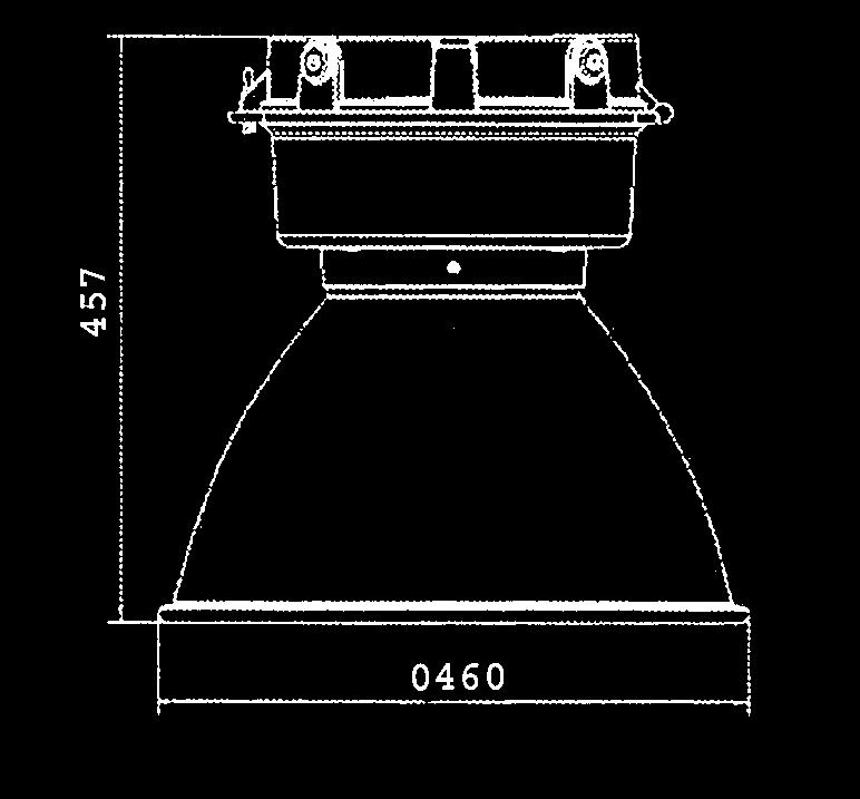
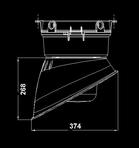

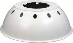
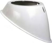
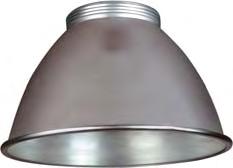
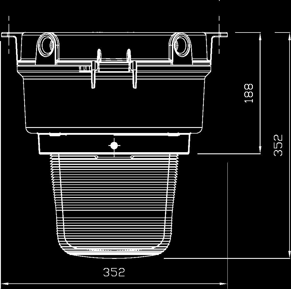

94 ECLIPSE RANGE 94 JUNIOR Ø9 Ø9 ECLIPSE II Angle reflector Dome reflector Sealed spun reflector Prismatic glass refractor


95 MOUNTING VARIATIONS and ACCESSORIES 95 ECLIPSE II MOUNTING ACCESSORIES CEILING and FLUSH MOUNTING WALL MOUNTING STANCHION MOUNTING TO SUIT POLE DIAMETER 70mm (1 1 / 2 NPT threaded pipe (I/D 44mm max) PENDANT MOUNTING
96 PROTECTA 96 SURFACE MOUNTED FLUORESCENT The Protecta is a proven and reliable T8 fluorescent luminaire. The Protecta s rugged, corrosion resistant construction (IP66/IP67) combined with an advanced high frequency ballast ensure minimum product maintenance is required. When access is required the Protecta Industrial features an easy access clamp bar and automatic lamp de-energisation to allow quick and easy re-lamping. Standard Specification Features Ingress Protection Enclosure Entries Termination Reflector/Gear-tray Mounting Control Gear Relamping IP66/67 to EN60529 GRP body with clear polycarbonate diffuser and brass suspension points 4 x M20 cable entries (2 each end) Quick release mains terminals - 3 core 4mm² max. conductor with looping and 16A rating through wiring. (6mm² terminations available - /SC option) White polyester painted zinc coated steel Two M8 brass inserts on rear of body High frequency electronic control gear Via quick-release diffuser clamp and hinged diffuser Simple rugged construction Full length easy access diffuser clamp Hinged cover Standard fixing centres When fitted high frequency control gear gives 50/60Hz operation, high power factor correction and regulation of lamp output Quick release mains terminals DTS-01 deluge tested Vibration tested to comply with Lloyds/DNV A copper and iron version is also available. To order substitute /HF with /ES and specify the voltage Electrical Supply V 50/60Hz
97 INDUSTRIAL and MARINE APPLICATIONS 97 Std. Cat No. Wattage Lamp TClass Lampholder Weight PRGI/118/BI/HF 1x18W Fluorescent T8 G13 6kg PRGI/218/BI/HF 2x18W Fluorescent T8 G13 6.1kg PRGI/136/BI/HF 1x36W Fluorescent T8 G13 9.6kg PRGI/236/BI/HF 2x36W Fluorescent T8 G13 9.8kg Options - Suffix to Catalogue No. /--- Specific voltage - Copper/iron ballasts: 120, 220, 230, 254V /3P 3 phase termination facility (not available if looping is required) /ES Electronic start (copper/iron ballast only) /M25 M25 cable entry /60 /EL 60Hz supply (copper/iron ballasts only) Extra live termination (compatible with 4 core switched emergency models) /SC /SB Screwed connection terminal block (up to 6mm² conductors) Stainless steel mounting bush /MF Mains fuse /SE Spigot entry Accessories Should be ordered separately Pole mounting bracket assembly (38-42mm diameter poles) Pole mounting bracket assembly (48-52mm diameter poles) Pole mounting bracket assembly (58-62mm diameter poles) Hook type ceiling bracket assembly Ceiling bracket assembly Flush mounting wall bracket assembly Eyebolt mounting assembly Looping Kit (allows looping from both ends of luminaire) 18W wall mounting outreach bracket (use with SPOL ) Catalogue Order Code SPOL SPOL SPOL SPRO SPRO SPRO SPRO SPROT-0021 NPRO W wall mounting outreach bracket (use with SPOL ) Product design and specifications are subject to change without notice, please check the Chalmit website for latest specifications. NPRO4-0012

98 PROTECTA E 98 EMERGENCY FLUORESCENT The Protecta Industrial has the same rugged and proven design as the Ex Protecta. This includes high ingress protection with DTS-01 deluge compliance and vibration resistance in accordance with Lloyds/DNV standards. The Emergency version also features an internal battery to allow operation in the event of mains power failure. Standard Specification Features Ingress Protection Enclosure Entries Termination Reflector/Gear-tray Mounting Control Gear Relamping IP66/67 to EN60529 GRP body with clear polycarbonate diffuser and brass suspension points 4 x M20 cable entries (2 each end) Quick release mains terminals - 3 core 4mm² max. conductor with looping and 16A rating through wiring. (6mm² terminations available - /SC option) White polyester painted zinc coated steel Two M8 brass inserts on rear of body High frequency ballast & invertor c/w battery pack Via quick-release diffuser clamp and hinged diffuser Simple rugged construction Full length easy access diffuser clamp Standard fixing centres High frequency control gear gives 50/60Hz operation, high power factor correction and regulation of lamp output Quick release mains terminals DTS-01 deluge tested Vibration tested to comply with Lloyds/DNV Optional battery monitoring and self-testing control gear Electrical Supply V 50/60Hz Battery Ni-Cd (6V) Duration 3 Hours to EN Emergency Output 32% of one lamp (18W) 14% of one lamp (36W)
99 INDUSTRIAL and MARINE APPLICATIONS 99 Std. Cat No. Wattage Lamp TClass Lampholder Weight PRGI/118/BI/EM 1x18W Fluorescent T8 G13 8.1kg PRGI/218/BI/EM 2x18W Fluorescent T8 G13 8.3kg PRGI/136/BI/EM 1x36W Fluorescent T8 G kg PRGI/236/BI/EM 2x36W Fluorescent T8 G kg Options - Suffix to Catalogue No. /120 /NM /MF /3P V Non-maintained (single lamp models only) Mains fuse 3 phase termination facility (not available if through wiring is required) /SC /SB /LBE /BMT Screwed connection terminal block (up to 6mm² conductors) Stainless steel mounting bush Looping both ends Battery monitoring and self-test /M25 M25 cable entry /SE Spigot entry Accessories Should be ordered separately Pole mounting bracket assembly (38-42mm diameter poles) Pole mounting bracket assembly (48-52mm diameter poles) Pole mounting bracket assembly (58-62mm diameter poles) Hook type ceiling bracket assembly Ceiling bracket assembly Flush mounting wall bracket assembly Eyebolt mounting assembly Looping Kit (allows looping from both ends of luminaire) 18W wall mounting outreach bracket (use with SPOL ) Catalogue Order Code SPOL SPOL SPOL SPRO SPRO SPRO SPRO SPROT-0021 NPRO W wall mounting outreach bracket (use with SPOL ) Product design and specifications are subject to change without notice, please check the Chalmit website for latest specifications. NPRO4-0012

100 PROTECTA S/S 100 STAINLESS STEEL FLUORESCENT The Protecta is also available in a stainless steel body version. This incorporates the same design and monitoring features found in the GRP body Protecta. The increased durability of its stainless steel construction makes this luminaire ideal for applications where there is a high risk of mechanical damage or exposure to chemical agents. Standard Specification Features Ingress Protection Enclosure Entries Termination Installation Reflector/Gear-tray Control Gear Relamping Electrical Supply IP66/67 to EN60529 Marine grade 316S31 stainless steel body with clear polycarbonate diffuser 4 x M20 cable entries (2 each end) Quick release mains terminals - 3 core 4mm² max. conductor with looping and 16A rating through wiring. (6mm² terminations available - /SC option) Two M8 tapped stainless steel inserts located on rear of body White polyester painted zinc coated steel High frequency electronic control gear Via quick-release diffuser clamp and hinged diffuser V 50/60Hz Emergency version 220/254V 50/60Hz Simple rugged construction Hinged cover with easily removeable cover clamps Standard fixing centres High frequency control gear gives 50/60Hz operation, high power factor correction and regulation of lamp output Quick release mains terminals Resistance to voltage fluctuations Optional battery monitoring and self-testing control gear A non-emergency copper and iron version is also available. To order substitute /HF with /ES and specify the voltage Battery Ni-Cd (6V) Duration 3 Hours Emergency Output 32% of one lamp (18W) 14% of one lamp (36W)
101 INDUSTRIAL and MARINE APPLICATIONS 101 Std. Cat No. Wattage Lamp TClass Lampholder Weight PRSI/118/BI/HF 1x18W Fluorescent T8 G13 5.9kg PRSI/218/BI/HF 2x18W Fluorescent T8 G13 6.2kg PRSI/136/BI/HF 1x36W Fluorescent T8 G13 9.6kg PRSI/236/BI/HF 2x36W Fluorescent T8 G kg PRSI/118/BI/EM 1x18W Fluorescent T8 G13 8.7kg PRSI/218/BI/EM 2x18W Fluorescent T8 G13 9.0kg PRSI/136/BI/EM 1x36W Fluorescent T8 G kg PRSI/236/BI/EM 2x36W Fluorescent T8 G kg Options - Suffix to Catalogue No. /120 /ES /--- /60 /EL V High frequency ballast (for /EM Emergency models only) Electronic start (copper/iron ballast only) Specific voltage (120*, 220, 230 & 254V only available copper/iron gear) 60Hz supply (copper/iron ballasts only) Extra live termination (Compatible with four core switched emergency models) * 120V copper/iron gear - non emergency only /M25 /SC /MF /3P /LBE /BMT M25 cable entries Screwed connection terminal block (up to 6mm² conductors) Mains fuse 3 phase termination facility Looping both ends Battery monitoring and self-test Accessories Should be ordered separately Catalogue Order Code Pole mounting bracket assembly (38-42mm diameter poles) SPOL Pole mounting bracket assembly (48-52mm diameter poles) SPOL Pole mounting bracket assembly (58-62mm diameter poles) SPOL Hook type ceiling bracket assembly SPRO Ceiling bracket assembly SPRO Flush mounting wall bracket assembly SPRO Eyebolt mounting assembly SPRO Looping Kit (allows looping from both ends of luminaire) SPROT W wall mounting outreach bracket (use with SPOL ) NPRO W wall mounting outreach bracket (use with SPOL ) NPRO Product design and specifications are subject to change without notice, please check the Chalmit website for latest specifications.
102 STERLING II 102 SURFACE MOUNTED FLUORESCENT The Sterling II is a high quality but cost effective fluorescent. Its lightweight and slimline construction make it simple to install and maintain. The luminaire has copper and iron control gear and is available with single and twin lamp versions. Standard Specification Features Ingress Protection Enclosure Entries IP65 to EN60529 GRP body with clear polycarbonate diffuser Stainless steel retaining clips 2 x 20mm clearance holes (one either end) Robust polycarbonate diffuser with stainless steel clips as standard Simple to install and maintain Lightweight and slim line construction Termination 4 core 4mm² max conductors Reflector/Gear-tray White polyester painted zinc coated steel Mounting 8mm clearance holes, sealing washers are provided Control Gear Copper & Iron switch start ballast Relamping Access via front diffuser secured by quick release stainless steel clips Electrical Supply 240V 50Hz Battery Ni-Cd (6V) Duration 3 Hours Emergency Output 32% of one lamp (18W) 14% of one lamp (36W) 9% of one lamp (58W)
103 INDUSTRIAL and MARINE APPLICATIONS 103 Std. Cat No. Wattage Voltage Lamp Type Lampholder Weight ST2I/118/BI 1x18W 240V 50Hz T8 Fluorescent G13 2.5kg ST2I/218/BI 2x18W 240V 50Hz T8 Fluorescent G13 3.2kg ST2I/136/BI 1x36W 240V 50Hz T8 Fluorescent G13 3.6kg ST2I/236/BI 2x36W 240V 50Hz T8 Fluorescent G13 4.2kg ST2I/158/BI 1x58W 240V 50Hz T8 Fluorescent G13 4.2kg ST2I/258/BI 2x58W 240V 50Hz T8 Fluorescent G13 5.1kg ST2I/118/BI/EM* 1x18W 240V 50Hz T8 Fluorescent G13 4.8kg ST2I/218/BI/EM 2x18W 240V 50Hz T8 Fluorescent G13 5.2kg ST2I/136/BI/EM* 1x36W 240V 50Hz T8 Fluorescent G13 5.6kg ST2I/236/BI/EM 2x36W 240V 50Hz T8 Fluorescent G13 6.1kg ST2I/158/BI/EM* 1x58W 240V 50Hz T8 Fluorescent G13 5.7kg ST2I/258/BI/EM 2x58W 240V 50Hz T8 Fluorescent G13 7.1kg * Emergency single lamp models are in twin lamp bodies Options - Suffix to Catalogue No. /NM /MF Non maintained emergency version (single lamp bodies only) Mains fuse /T /ES /EA Through wired Electronic starter External earth Dimensions 1 x 18 1 x 36 1 x 58 2 x 18 2 x 36 2 x 58 A B C D 106 Accessories Should be ordered separately Catalogue Order Code Pole mounting bracket assembly (38-42mm diameter poles) SPOL Pole mounting bracket assembly (48-52mm diameter poles) SPOL Pole mounting bracket assembly (58-62mm diameter poles) SPOL Hook type ceiling bracket assembly S Ceiling bracket assembly S Flush mounting wall bracket assembly S W wall mounting outreach bracket (use with SPOL ) NPRO W wall mounting outreach bracket (use with SPOL ) NPRO W wall mounting outreach bracket (use with SPOL ) NPRO Product design and specifications are subject to change without notice, please check the Chalmit website for latest specifications.

104 STERLING II H/F SURFACE MOUNTED 104 FLUORESCENT The Sterling II H/F features the same lightweight design but incorporates high frequency electronic control gear. Standard Specification Features Ingress Protection Enclosure Entries Termination Reflector/Gear-tray Mounting Control Gear Relamping Electrical Supply Battery Duration Emergency Output IP65 to EN60529 GRP body with clear polycarbonate diffuser Stainless Steel retaining clips 2 x 20mm clearance holes (one either end) 4 core 4mm² max conductors White polyester painted zinc coated steel 8mm clearance holes, sealing washers are provided High frequency electronic ballast Access via front diffuser secured by quick release stainless steel clips Non-emergency version - 120V-254V 50/60Hz 175V-270V DC Emergency version V 50/60Hz Ni-Cd (6V) 3 Hours 32% of one lamp (18W) 14% of one lamp (36W) 9% of one lamp (58W) Robust polycarbonate diffuser with stainless steel clips as standard High frequency control gear gives 50/60Hz operation, high power factor correction and regulation of lamp output Simple to install and maintain Lightweight and slim line construction
105 INDUSTRIAL and MARINE APPLICATIONS 105 Std. Cat No. Wattage Voltage Lamp Type Lampholder Weight ST2I/118/BI/HF 1x18W 120V-254V 50/60Hz T8 Fluorescent G13 2.3kg ST2I/218/BI/HF 2x18W 120V-254V 50/60Hz T8 Fluorescent G13 2.6kg ST2I/136/BI/HF 1x36W 120V-254V 50/60Hz T8 Fluorescent G13 3.3kg ST2I/236/BI/HF 2x36W 120V-254V 50/60Hz T8 Fluorescent G13 3.6kg ST2I/158/BI/HF 1x58W 120V-254V 50/60Hz T8 Fluorescent G13 3.7kg ST2I/258/BI/HF 2x58W 120V-254V 50/60Hz T8 Fluorescent G13 4.1kg ST2I/118/BI/EM/HF* 1x18W 220V-254V 50/60Hz T8 Fluorescent G13 4.3kg ST2I/218/BI/EM/HF 2x18W 220V-254V 50/60Hz T8 Fluorescent G13 4.6kg ST2I/136/BI/EM/HF* 1x36W 220V-254V 50/60Hz T8 Fluorescent G13 5.3kg ST2I/236/BI/EM/HF 2x36W 220V-254V 50/60Hz T8 Fluorescent G13 5.6kg ST2I/158/BI/EM/HF* 1x58W 220V-254V 50/60Hz T8 Fluorescent G13 5.7kg ST2I/258/BI/EM/HF 2x58W 220V-254V 50/60Hz T8 Fluorescent G13 6.1kg * Emergency single lamp models are in twin lamp bodies Options - Suffix to Catalogue No. /120 /NM V 50/60Hz High frequency ballast (Emergency version only) Non maintained emergency version (single lamp bodies only) /MF /T /EA Mains fuse Through wired External earth Dimensions 1 x 18 1 x 36 1 x 58 2 x 18 2 x 36 2 x 58 A B C D 106 Accessories Should be ordered separately Catalogue Order Code Pole mounting bracket assembly (38-42mm diameter poles) SPOL Pole mounting bracket assembly (48-52mm diameter poles) SPOL Pole mounting bracket assembly (58-62mm diameter poles) SPOL Hook type ceiling bracket assembly S Ceiling bracket assembly S Flush mounting wall bracket assembly S W wall mounting outreach bracket (use with SPOL ) NPRO W wall mounting outreach bracket (use with SPOL ) NPRO W wall mounting outreach bracket (use with SPOL ) NPRO Product design and specifications are subject to change without notice, please check the Chalmit website for latest specifications.
106 STERLING II S/S 106 STAINLESS STEEL FLUORESCENT The Sterling II is also available in a stainless steel body version. This incorporates the same design and protection features found in the GRP body Sterling II. The increased durability of its stainless steel construction makes this luminaire ideal for applications where there is a high risk of mechanical damage or exposure to chemical agents. Standard Specification Features Ingress Protection Enclosure Reflector/Geartray Entries Termination IP65 to EN60529 Marine grade 316S31 stainless steel body, clear polycarbonate diffuser & quick release stainless steel clips White epoxy polyester coated steel 3 x 20mm entries (2 at one end, 1 at other end) Looping & through wiring for 3 core 4mm² conductors (4 core on Emergency models) Marine grade stainless steel body and polycarbonate diffuser 3 clips per side on 18W, 4 on 36W and 5 on 58W Mains connection terminals fixed to body Gear tray suspended and fitted with control gear for ease of maintenance Installation Access via two 8mm holes on rear of body Control Gear Copper & iron switchstart ballast Relamping Via quick release stainless steel clips Electrical Supply 240V 50Hz (Always state V/Hz when ordering) Battery Ni-Cd (6V) Duration 3 Hours Emergency Output 32% of one lamp (18W) 14% of one lamp (36W) 9% of one lamp (58W)
107 INDUSTRIAL and MARINE APPLICATIONS 107 Std. Cat No. Wattage Lamp Type Lampholder Weight SS2I/118/BI 1x18W T8 Fluorescent G13 4.2kg SS2I/218/BI 2x18W T8 Fluorescent G13 3.6kg SS2I/136/BI 1x36W T8 Fluorescent G13 4.2kg SS2I/236/BI 2x36W T8 Fluorescent G13 4.8kg SS2I/158/BI 1x58W T8 Fluorescent G13 6.1kg SS2I/258/BI 2x58W T8 Fluorescent G13 6.5kg SS2I/118/BI/EM 1x18W T8 Fluorescent G13 7.0kg SS2I/218/BI/EM 2x18W T8 Fluorescent G13 6.4kg SS2I/136/BI/EM 1x36W T8 Fluorescent G13 7.0kg SS2I/236/BI/EM 2x36W T8 Fluorescent G13 7.6kg SS2I/158/BI/EM 1x58W T8 Fluorescent G13 8.9kg SS2I/258/BI/EM 2x58W T8 Fluorescent G13 9.3kg Options - Suffix to Catalogue No. /ES Electronic start (copper & iron ballast only) /60 60Hz supply (copper/iron ballasts only) / Specific voltage: 120V Emergency only (if 120V non-emergency is required, a High Frequency (HF) version is available) /M25 /CM M25 cable entries Body c/w ceiling mounting brackets B D 3x20mm Dia. cable entry clearance holes. 2x1 end 1x opposite. C A Dimensions 1 x 18 1 x 36 1 x 58 2 x 18 2 x 36 2 x 58 A B C 172 D 106 Accessories Should be ordered separately Catalogue Order Code Pole mounting bracket assembly (38-42mm diameter poles) SPOL Pole mounting bracket assembly (48-52mm diameter poles) SPOL Pole mounting bracket assembly (58-62mm diameter poles) SPOL Hook type ceiling bracket assembly S Ceiling bracket assembly S Flush mounting wall bracket assembly S W wall mounting outreach bracket (use with SPOL ) NPRO W wall mounting outreach bracket (use with SPOL ) NPRO W wall mounting outreach bracket (use with SPOL ) NPRO Product design and specifications are subject to change without notice, please check the Chalmit website for latest specifications.

108 STERLING II S/S H/F 108 STAINLESS FLUORESCENT The Sterling II H/F is also available in a stainless steel body version. This incorporates the same design and protection features found in the GRP body Sterling II. The increased durability of its stainless steel construction makes this luminaire ideal for applications where there is a high risk of mechanical damage or exposure to chemical agents. Standard Specification Features Ingress Protection Enclosure Reflector/Geartray Entries Termination IP65 to EN60529 Marine grade 316S31 stainless steel body, clear polycarbonate diffuser & quick release stainless steel clips White epoxy polyester coated steel 3 x 20mm entries (2 at one end, 1 at other end) Looping & through wiring for 3 core 4mm² conductors (4 core on Emergency models) Marine grade stainless steel body and polycarbonate diffuser High frequency control gear gives 50/60Hz operation, high power factor correction and regulation of lamp output Mains connection terminals fixed to body Gear tray suspended and fitted with control gear for ease of maintenance Installation Access via two 8mm holes on rear of body Control Gear High frequency electronic control gear Relamping Via quick release stainless steel clips Electrical Supply 240V 50Hz (Always state V/Hz when ordering) Battery Ni-Cd (6V) Duration 3 Hours Emergency Output 32% of one lamp (18W) 14% of one lamp (36W) 9% of one lamp (58W)
109 INDUSTRIAL and MARINE APPLICATIONS 109 Std. Cat No. Wattage Lamp Type Lampholder Weight SS2I/118/BI/HF 1x18W T8 Fluorescent G13 4.2kg SS2I/218/BI/HF 2x18W T8 Fluorescent G13 3.6kg SS2I/136/BI/HF 1x36W T8 Fluorescent G13 4.2kg SS2I/236/BI/HF 2x36W T8 Fluorescent G13 4.8kg SS2I/158/BI/HF 1x58W T8 Fluorescent G13 6.1kg SS2I/258/BI/HF 2x58W T8 Fluorescent G13 6.5kg SS2I/118/BI/EM/HF 1x18W T8 Fluorescent G13 7.0kg SS2I/218/BI/EM/HF 2x18W T8 Fluorescent G13 6.4kg SS2I/136/BI/EM/HF 1x36W T8 Fluorescent G13 7.0kg SS2I/236/BI/EM/HF 2x36W T8 Fluorescent G13 7.6kg SS2I/158/BI/EM/HF 1x58W T8 Fluorescent G13 8.9kg SS2I/258/BI/EM/HF 2x58W T8 Fluorescent G13 9.3kg Options - Suffix to Catalogue No. / V Emergency only /M25 (if 120V non-emergency is required, a High Frequency (HF) version is available) /CM M25 cable entries Body c/w ceiling mounting brackets B D 3x20mm Dia. cable entry clearance holes. 2x1 end 1x opposite. C A Dimensions 1 x 18 1 x 36 1 x 58 2 x 18 2 x 36 2 x 58 A B C 172 D 106 Accessories Should be ordered separately Catalogue Order Code Pole mounting bracket assembly (38-42mm diameter poles) SPOL Pole mounting bracket assembly (48-52mm diameter poles) SPOL Pole mounting bracket assembly (58-62mm diameter poles) SPOL Hook type ceiling bracket assembly S Ceiling bracket assembly S Flush mounting wall bracket assembly S W wall mounting outreach bracket (use with SPOL ) NPRO W wall mounting outreach bracket (use with SPOL ) NPRO W wall mounting outreach bracket (use with SPOL ) NPRO Product design and specifications are subject to change without notice, please check the Chalmit website for latest specifications.

110 ACCLAIM RECESSED FLUORESCENT 110 The Acclaim is a recessed fluorescent specifically designed for use in solid or plank ceiling types. The luminaire is SOLAS B15 approved and suitable for use in offshore accommodation modules for both task and emergency lighting. To allow safe and easy maintenance Acclaim features automatic lamp de-energisation upon opening. An emergency version with internal battery is also available. Standard Specification Features Ingress Protection Enclosure Entries Internal Wiring Termination Mounting Control Gear IP54 to EN60529 White polyester painted zintec body and frame. Clear polycarbonate diffuser 4 x 20mm clearance holes (supplied plug) Stranded, heat resistant wiring up to 105 C Quick release mains terminals - 3 core 4mm² max. conductor with looping and through wiring facility (4 core on emergency). (6mm² terminations available - /SC option) Swing out side arms (also suitable for drop rod mounting through 9mm holes) High Frequency Suitable for various ceiling types Quick release mains terminals Resistant to voltage fluctuations Local switching arrangement as standard Electronic control gear gives 50/60Hz operation, high power factor correction and regulation of lamp output dc operation (non emergency) 3 hour emergency duration B15 SOLAS fire rating - appropriate insulation is required over the luminaire Optional battery monitoring and self-testing control gear Relamping Via front cover, secured by pan head screws Electrical Supply V 50/60Hz, V 50/60Hz (emergency model) Always state V/Hz when ordering Battery duration 3 Hours (emergency models)

 /EL Extra live termination facility (compatible with 4 core switched emergency circuits) /LG /PD /MF Low glare")
 Adjust to ensure ceiling integrity Low Glare Louvre (/LG) Product design and specifications are subject to change without notice,")
111 INDUSTRIAL and MARINE APPLICATIONS 111 Std. Cat No. Wattage Lamp Type Lampholder Weight ACLI/218/BI 2x18W T8 Fluorescent G13 6.0kg ACLI/236/BI 2x36W T8 Fluorescent G kg ACLI/218/BI/EM 2x18W T8 Fluorescent G13 8.5kg ACLI/236/BI/EM 2x36W T8 Fluorescent G kg Options - Suffix to Catalogue No. /120 Specific voltage (110/130 - Emergency version only) /SC Screwed connection terminal block (up to 6mm² conductors) /PC Solid plank ceiling /DIM Analogue dimming /3P 3 phase termination facility (not available if through wiring required) /EL Extra live termination facility (compatible with 4 core switched emergency circuits) /LG /PD /MF Low glare louvre Prismatic diffuser Mains fuse /25 25mm cable entries /BMT Battery monitoring and self-test Please refer to pages 32 and 33 for ceiling types Standard Clear Diffuser Single screw height adjustment Prismatic Diffuser (/PD) Adjust to ensure ceiling integrity Low Glare Louvre (/LG) Product design and specifications are subject to change without notice, please check the Chalmit website for latest specifications.

112 CURIE 112 RECESSED FLUORESCENT The Curie is a recessed fluorescent specifically designed for use in solid or modular ceiling types. The luminaire is SOLAS B15 approved and suitable for use in offshore accommodation modules for both task and emergency lighting. Standard Specification Features Ingress Protection Enclosure Entries Internal Wiring Termination Mounting Control Gear Relamping Electrical Supply IP44 to EN (Front cover only) White polyester painted zintec body and frame Prismatic polycarbonate diffuser 2 x 20mm clearance holes (supplied plug) Stranded, heat resistant wiring up to 105 C 4 core 4mm² max conductors Side brackets with adjustable arms (solid ceilings) Rotating cams (Exposed T and Spring T ceilings). There is also a provision for drop rod mounting High Frequency Via front cover, secured by pan head screws V 50/60Hz AC/DC Suitable for solid and modular ceiling types B15 SOLAS fire rating - appropriate insulation is required over the luminaire Option of battery management monitoring & automatic self test Simple and easy access via front cover for lamp replacement and maintenance Electronic control gear gives 50/60Hz operation, high power factor correction and regulation of lamp output dc operation (non emergency) Local switching arrangement as standard Optional battery monitoring and self-testing control gear Battery duration 3 Hours (emergency models)

113 INDUSTRIAL and MARINE APPLICATIONS 113 Std. Cat No. Wattage Lamp Type Lampholder Weight CURI/218/BI* 2x18W T8 fluorescent G13 8.0kg CURI/418/BI 4x18W T8 fluorescent G13 8.0kg CURI/236/BI* 2x36W T8 fluorescent G kg CURI/436/BI 4x36W T8 fluorescent G kg CURI/218/BI/EM* 2x18W T8 fluorescent G13 8.6kg CURI/418/BI/EM 4x18W T8 fluorescent G13 8.6kg CURI/236/BI/EM* 2x36W T8 fluorescent G kg CURI/436/BI/EM 4x36W T8 fluorescent G kg *Only available in 600mm x 600mm (2 x 18W) and 600mm x 1200mm (2 x 36W body) Note: All above standard versions are for non modular ceilings. Modular ceiling types require the /MES suffix. Please specify voltage at time of enquiry/order Options - Suffix to Catalogue No. /MES /120 /254 Modular (Spring T or Exposed T ceiling types) Specific voltage (110/120V) Specific voltage (254V) /25 /LG /BMT 25mm cable entries Low glare louvre Battery monitoring & self test /SC Screwed connection terminal block (up to 6mm² conductors) /2L 2 lamp emergency mode Please refer to pages 114 and 115 for ceiling types and dimensions /LG - Low glare louvre Accessories Should be ordered separately Catalogue Order Code Adjustable arm mounting kit Product design and specifications are subject to change without notice, please check the Chalmit website for latest specifications. SMOKI-00002
114 CEILING TYPE OPTIONS 114 CAM Front View Rear View View of Exposed T Ceiling with integrated luminaire, typical 600mm x 600mm tile grid mounting system (/MES). CAM Front View Rear View View of Spring T Ceiling with integrated luminaire, typical 600mm x 600mm tile grid mounting system (/MES). Adjustable side arms Hook down mounting brackets Hook up mounting brackets View of Solid Ceiling with integrated luminaire.
115 DIMENSIONS 115 Overall Height (including cover) 112mm Spring T bracket X Sectional View W W W W Holes Ø8 4 x 20mm Holes for cable entry 18W W W W Exposed T bracket X Sectional View Dimensions in millimetres Exposed T and Spring T Ceiling types (/MES) dimensions. Overall Height (including cover) 112mm 4 Holes Ø8 X Sectional View x 20mm Holes for cable entry 18W W W W X Sectional View Dimensions in millimetres Solid Ceiling dimensions.


116 NexLED LED Bulkhead 116 NexLED with Exit Sign kit The NexLED bulkhead utilises the latest LED technology to provide instant illumination. The NexLED requires no re-lamping making it virtually maintenance free and unaffected by low temperatures. This combination makes the NexLED ideal for extreme environmental applications. Coloured LED options are also available. NexLED with green LED s Standard Specification Features Enclosure Reflector Entry Termination Installation Lamp Type Cast aluminium with toughened glass and silicone gasket Brushed aluminium 3 x M20 cable entries 4 core 4mm² max conductor with looping Surface mounted, 4 mounting holes located outside of seal 2 x 1W light emitting diodes or 8 x 1W light emitting diodes. Colour: white Highly visible, instant light Easy to install and maintain Ultra long life, no relamping required Very low power consumption 100% output in emergency mode (Up to 3 hours) Rechargable Ni-mH batteries with charging indication Compatible with UPS systems Control Gear Electronic Burning Position Universal Ingress Protection IP66/67 to EN Emergency Duration 3 hours (emergency models) Electrical Supply V ac/dc

117 INDUSTRIAL and MARINE APPLICATIONS 117 Std. Cat No. Wattage Lamp Type Ambient C Weight NELI/201/LE 2W Light Emitting Diode -20 to kg NELI/801/LE 8W Light Emitting Diode -20 to kg NELI/201/LE/EM 2W Light Emitting Diode -20 to kg NELI/801/LE/EM 8W Light Emitting Diode -20 to kg Options - Suffix to Catalogue No. /RDE Red LED s /ADE Amber LED s /GDE Green LED s /LT Low temperature -45 C to +45 C /BDE Blue LED s Accessories Should be ordered separately Green exit sign kit (4 labels - up, down, left and right) Catalogue Order Code SNEL Product design and specifications are subject to change without notice, please check the Chalmit website for latest specifications.

118 NEXXUS HEAVY DUTY BULKHEAD 118 The Nexxus is a corrosion resistant bulkhead with a prismatic glass lens. It is available with a range of lamp types and is suitable for low temperature operation. For ease of installation and maintenance the fixing points are located outside the restricted breathing enclosure. Standard Specification Features Ingress Protection Enclosure Entries Termination Reflector Mounting Relamping IP66/67 to EN60529 Epoxy painted aluminium alloy LM6 body with prismatic glass lens, silicone rubber gasket and stainless steel fixings 3 x M20 cable entries 3 core 6mm² max conductors with looping or through wiring High purity anodised aluminium 4 x 7mm clearance holes in body fixing channel Access via glass cover secured by 4 stainless steel screws Improved light output Easy control gear replacement Fixing points outside restricted breathing enclosure High corrosion resistance Suitable for ceiling or wall mounting Through wire or looping as standard Prismatic lens Suitable for low temperature applications Control Gear Internal copper/iron ballast with ignitor and PFC capacitors (HID lamp models) Electrical Supply V 50Hz (50W HPS lamp model) V 50Hz (70W & 80W models) 240V 50Hz (CFL models) 250V Max ac/dc (50Hz GLS lamp model)

119 INDUSTRIAL and MARINE APPLICATIONS 119 Std. Cat No. Wattage Lamp Type Lampholder Weight NEXI/050/HS 50W HPS E27 7.2kg NEXI/070/MS 70W HPS/Metal Halide E27 7.7kg NEXI/080/MV 80W Mercury Vapour E27 7.2kg NEXI/113/CF 1x13W CFL G24 6.2kg NEXI/118/CF 1x18W CFL G24 6.2kg NEXI/126/CF 1x26W CFL G24 6.2kg NEXI/213/CF 2x13W CFL G24 6.7kg NEXI/218/CF 2x18W CFL G24 6.7kg NEXI/226/CF 2x26W CFL G24 6.7kg NEXI/200/GL 200W GLS E27 5.7kg Options - Suffix to Catalogue No. /60 60Hz (50W, 70W and 80W only) /MF Mains fuse /TI Timed cut out ignitor Accessories Should be ordered separately Catalogue Order Code Wire Guard Assembly Product design and specifications are subject to change without notice, please check the Chalmit website for latest specifications. SNEX1-0001


, 0.090m² (854), 0.")
120 800 SERIES FLOODLIGHTS 120 The 854 with anti-glare shield Recommended maximum aiming angle 20 from horizontal plane The 800 series is a range of stainless steel asymmetrical floodlights. These floods are designed for optimum light output and efficiency to ensure the minimum number of luminaires is required. The 854 with wire guard Standard Specification Features Ingress Protection Enclosure Entries Termination Reflector Mounting IP66/67 to EN60529 Marine grade 316S31 stainless steel body with toughened glass window, silicone rubber gasket 2 x M20 cable entries 3 core 4mm² max conductors Wide beam high purity anodised aluminium Adjustable stirrup bracket Marine grade stainless steel body and toughened glass cover Quick release fasteners for ease of relamping and maintenance Suspended cover front photometrically superior asymmetric reflector Suitable for low temperature applications Standard control gear for use with IEC lamps Windage 0.052m² (844), 0.090m² (854), 0.107m² (864) Control Gear Internal (with remote option using control gear box) Relamping Via front cover (c/w safety chains) and quick release clips Electrical Supply 220, 230, 240, 254V 50Hz for SON-T & MBI-T lamp models. 250V Max ac/dc for tungsten halogen lamps
121 INDUSTRIAL and MARINE APPLICATIONS 121 Std. Cat No. Wattage Lamp Type Lampholder Weight 844I/070/MS 70W HPS/Metal Halide E kg 854I/100/HS 100W HPS E kg 854I/150/MS 150W HPS/Metal Halide E kg 854I/250/MS 250W HPS/Metal Halide E kg 854I/400/MS* 400W HPS/Metal Halide E kg 864I/400/MS 400W HPS/Metal Halide E kg 854I/500/TH 500W Single ended T/Halogen E kg 864I/600/HS* 600W HPS E kg 100/120V Cat Nos. The following models are for 120V, 50Hz as standard: 864I/150/HS/120** 150W HPS E kg 864I/250/HS/120** 250w HPS E kg 864I/400/HS/120*** 400W HPSe E kg * Ignitor only fitted within floodlight. Remote gear box required (see Universal Box) ** c/w IEC control gear 110/120V supply. *** Supplied with remote transformer box for 110/120V supply. (Control gear fitted for IEC lamps). All control gear fitted for use with European lamps (IEC). Note: Please specify voltage at time of enquiry/order Options - Suffix to Catalogue No. /60 /M25 /N /TI /WA /NEC 60Hz 2 x M25 cable entries Narrow beam reflector Timed cut-out ignitor Suitable for wire guard or anti-glare shield NEC control gear (for US lamps only) (120, 208, 240 and 277V) Accessories Should be ordered separately Catalogue Order Code Pole mounting bracket assembly (50-100mm diameter poles) S Pole mounting bracket assembly - 854/864 (48-70mm diameter poles) S Spigot top mounting bracket assembly - 854/864 (70-82mm diameter poles) S Wire guard (requires WA suffix when ordering) S Wire guard (requires WA suffix when ordering) S Wire guard (requires WA suffix when ordering) S Anti-glare shield (requires WA suffix when ordering) S Anti-glare shield (requires WA suffix when ordering) S Anti-glare shield (requires WA suffix when ordering) S Product design and specifications are subject to change without notice, please check the Chalmit website for latest specifications.


122 MICRONEX and MAXINEX 122 FLOODLIGHTS Recommended maximum aiming angle 20 from horizontal plane The Maxinex is a lightweight asymmetric floodlight. Its compact design ensures low wind resistance so is ideal for high mast applications. The reflector design allows light to be thrown forward long distances whilst still lighting below the pole. The Micronex is a compact version ideal for directional control lighting at low mounting heights such as perimeter lighting and loading areas. Standard Specification Features Ingress Protection Enclosure Reflector Cable Entry Termination Installation Windage Relamping Control Gear IP66/67 to BS EN60529 Aluminium body, glass lens, stainless steel fasteners Wide beam high purity anodised aluminium Maxinex (150W - 400W) - 2 x M20 cable entries (looping) Micronex (70W) - 1 x M20 cable entry 3 core 6mm² conductors Via stirrup bracket, fitted as standard 0.029m² (Micronex), 0.090m² (Maxinex) Via hinged front cover Internal Lightweight High corrosion resistance All stainless steel fasteners Hinged front cover for easy access High efficiency asymmetric reflector design Low windage of 0.08m 2 (Micronex) and 0.25m 2 (Maxinex) Choice of metal halide or high pressure sodium (HPS) lamps Suitable for low temperature applications P F Correction 0.85 minimum Electrical Supply V 50Hz
123 INDUSTRIAL and MARINE APPLICATIONS 123 Std. Cat No. Wattage Lamp Lampholder T Class Ambient C Weight MICI/070/MS 70W Double Ended HPS/Metal Halide Rx7 s T kg MAXI/150/MS 150W HPS/Metal Halide E40 T kg MAXI/250/MS 250W HPS/Metal Halide E40 T kg MAXI/400/MS 400W HPS/Metal Halide E40 T3 T3 45 (HPS) 30(MH) 17.0kg Note: Please specify voltage at time of enquiry/order Options - Suffix to Catalogue No. /60 60Hz /TI Timed ignitor (Maxinex only) MICRONEX MAXINEX Accessories Should be ordered separately Pole mounting bracket - Micronex (48-60mm pole diameter) Pole mounting bracket - Maxinex (48-60mm pole diameter) Catalogue Order Code SMIC SMAX Product design and specifications are subject to change without notice, please check the Chalmit website for latest specifications.


124 DEXLUX STAINLESS STEEL FLOODLIGHT 124 Dexlux with anti-glare shield The Dexlux is a stainless steel floodlight that offers high levels of corrosion resistance. It is ideally suited for use in marine or saline environments. Standard Specification Features Ingress Protection Enclosure IP66/67 to EN S31 marine grade stainless steel body with toughened glass window. Silicone rubber gasket and GRP terminal box Lightweight marine grade 316S31 stainless steel body and toughened glass cover Suspended cover front Entries 1 x 20mm clearance hole in junction box Termination 3 core 6mm² max conductors Reflector Wide beam high purity anodised aluminium Mounting Stirrup bracket Windage 0.047m² (200W), 0.058m² (500W), 0.114m² (1000W) Control Gear N/A Relamping Via front cover and quick release clips Electrical Supply 250V Max ac/dc
125 INDUSTRIAL and MARINE APPLICATIONS 125 Std. Cat No. Wattage Lamp Lampholder Weight DEXI/200/TL 200W Tungsten-Halogen R7s 5.0kg DEXI/500/TL 500W Tungsten-Halogen R7s 6.5kg DEXI/1000/TL 1000W Tungsten-Halogen R7s 9.0kg Options - Suffix to Catalogue No. /25 1 x 25mm cable entry /WA Suitable for wire guard or anti-glare shield DIMS 200W 500W 1000W A B C D E F G H WEIGHT 5.0kg 6.5kg 9.0kg Accessories Should be ordered separately Catalogue Order Code Anti-vibration damper assembly S Pole-mounting bracket assembly (48-64mm pole diameter) S Anti-glare shield - 200W (requires /WA suffix when ordering) N Anti-glare shield - 500W (requires /WA suffix when ordering) N Anti-glare shield W (requires /WA suffix when ordering) N Wire Guard - 200W (requires /WA suffix when ordering) E Wire Guard - 500W (requires /WA suffix when ordering) E Wire Guard W (requires /WA suffix when ordering) E Product design and specifications are subject to change without notice, please check the Chalmit website for latest specifications.


126 503 FLOODLIGHT W HPS 1000W and 2000W versions The 503 is a high powered floodlight with a wide ambient temperature range. The high upper ambient and corrosion resistant aluminium constriction, make the 503 ideal for use even in the hottest and hostile environments. Standard Specification Features Ingress Protection Enclosure Entries IP66/67 to EN60529 Marine grade aluminium LM6 alloy body with toughened glass window, silicone rubber gasket 1 x M20 cable entries Highly resistant to corrosion and mechanical damage All A4 stainless steel fasteners High ambient applications Termination 3 core 4mm² max conductors Reflector Wide beam high purity anodised aluminium Mounting Foot mounted Windage 0.227m² Control Gear Refer to universal control gear box for models with HPS or Metal Halide lamps Relamping Via end cover secured by stainless steel screws Electrical Supply 250V Max ac/dc for tungsten halogen lamps
127 INDUSTRIAL and MARINE APPLICATIONS 127 Std. Cat No. Wattage Lamp Type Lampholder Weight 503I/600/HS/IG* 600W HPS E40 25kg 503I/1000/HS/IG* 1000W HPS E40 25kg 503I/1000/MH/IG* 1000W Metal Halide E40 25kg 503I/2000/MH/IG* 2000W Metal Halide E40 25kg 503I/2000/TH 2000W Single ended T/Halogen E40 25kg * Remote gearbox required (see Universal Box), page 134 or (502 box), page 136. Options - Suffix to Catalogue No. /P PTFE coating /N Narrow beam reflector Accessories Should be ordered separately Catalogue Order Code Pole mounting bracket assembly (64-114mm pole diameter) S Swinging jib bracket S Anti-glare shield S Wire guard S Product design and specifications are subject to change without notice, please check the Chalmit website for latest specifications.


 0.134m (> 150W Glass) 0.")
128 ECLIPSE II WELL-GLASS 128 The Eclipse II with external reflector The Eclipse II wellglass has been designed to make installation quick and simple. The lamp and gear chambers are separated for easy maintenance and require no special cable glands. The luminaire also features a swing barrel nut system. This allows prior installation and wiring of the mounting base without the need to support the body and lamps. This unique design saves on both time and labour costs. The Eclipse II with glass refractor Standard Specification Features Ingress Protection Enclosure Entry Termination IP66 to EN60529 Painted aluminium body with glass globe Silicone rubber gasket Single stainless steel barrel nut fastener 4 x M20 cable entries 3 core 6mm² max, with looping Easy access for wiring and control gear Corrosion resistant High, medium and low bay lighting Excellent light distribution Wide range of mounting options available Installation Ceiling mounting Windage 0.107m (up to 150W Glass) 0.134m (> 150W Glass) 0.210m (Enclosed Reflector) Control Gear Internal copper/iron ballast with ignitor and PFC correction capacitors Relamping Access via lamp chamber Burning Position Up to 25 off vertical Electrical Supply 220, 230, 240V 50Hz (50, 80, 100 & 125W) 220, 230, 240, 254V 50Hz (70, 150, 250 & 400W)
129 INDUSTRIAL and MARINE APPLICATIONS 129 Std. Cat No. Wattage Lamp Type Lampholder Weight EC2I/050/HS 50W HPS E27 7.5kg EC2I/070/MS 70W HPS/Metal Halide E27 8.0kg EC2I/100/HS 100W HPS E40 9.0kg EC2I/150/MS 150W HPS/Metal Halide E kg EC2I/250/MS 250W HPS/Metal Halide E kg EC2I/400/MS 400W HPS/Metal Halide E kg EC2I/080/MV 80W Mercury Vapour E27 7.5kg EC2I/125/MV 125W Mercury Vapour E27 8.0kg EC2I/250/MV 250W Mercury Vapour E kg EC2I/400/MV 400W Mercury Vapour E kg For mounting options refer to page 95. Note: Please specify voltage at time of enquiry/order Options - Suffix to Catalogue No. /60 60Hz /PE Pendant mounted version /M25 M25 cable entries /TI Timed cut out ignitor /WM Wall mounted version /R Prismatic glass refractor (up to 150W) /ST Stanchion mounted version /ER Sealed spun reflector 457 8mm Ø Accessories Should be ordered separately Catalogue Order Code Wire guard for low wattage glass globe (up to 150W) E Wire guard for high wattage glass globe (250W/400W) E Wire guard for enclosed reflector E Dome reflector 30 angled reflector HEC HEC Product design and specifications are subject to change without notice, please check the Chalmit website for latest specifications.


130 ECLIPSE JUNIOR WELL-GLASS 130 The Eclipse Junior with external reflector The Eclipse Junior is a compact wellglass that incorporates the low maintenance features of the Eclipse II. Its low profile design and range of mounting options, offers an all round lighting solution in areas of limited space. The Eclipse Junior with wire guard Standard Specification Features Ingress Protection Enclosure Entries IP66/67 to EN60529 Marine grade aluminium LM6 alloy body with toughened glass globe, silicone rubber gasket 1 x M20 cable entries Compact size and low weight Easy access for wiring and control gear Corrosion resistant Excellent light distribution Termination 3 core 4mm² max conductors Reflector Wide beam high purity anodised aluminium Mounting Foot mounted Windage 0.066m² Control Gear Refer to universal control gear box for models with HPS or Metal Halide lamps Relamping Via end cover secured by stainless steel screws Electrical Supply 250V Max ac/dc for tungsten halogen lamps
131 INDUSTRIAL and MARINE APPLICATIONS 131 Std. Cat No. Wattage Lamp Type Lampholder Weight ECJI/050/HS 50W HPS E27 5.5kg ECJI/070/MS 70W HPS/Metal Halide E27 6.0kg ECJI/080/MV 80W MBFU E27 6.0kg ECJI/125/MV 125W MBFU E27 6.5kg ECJI/150/GLS 150W GLS E27 5.0kg For mounting options refer to page 94. Note: Please specify voltage at time of enquiry/order Options - Suffix to Catalogue No. /60 60Hz /ST Stanchion mounted version /WM Wall mounted version /PE Pendant mounted version Accessories Should be ordered separately Catalogue Order Code Wire guard (can be used in conjunction with reflectors) E Dome reflector SECL Angled reflector SECL Product design and specifications are subject to change without notice, please check the Chalmit website for latest specifications.

132 CHIEFTAIN II STREET LANTERN 132 The Chieftain II is a dedicated street lantern that provides high levels of diffused light. The body features integrated control gear and quick release fasteners to allow simple maintenance and re-lamping. Standard Specification Features Ingress Protection Enclosure Diffuser Bowl IP65, Gear compartment IP54 to EN6052 Body in cast aluminium, polyester powder finish Polycarbonate (Toughened glass diffuser available as an option) Control gear hosed within main body Quick release fasteners for easy access and maintenance Suitable for 48-60mm diameter poles Reflector Removable, high purity aluminium, anodised and highly polished Installation Spigot Entry Pole Diameter 48-60mm Relamping Quick release clips Lampholder E40 Burning Position Universal Electrical Supply 220/230/240/254V 50Hz (HPS/Metal Halide) 220/230/240V 50Hz (MBFU)
 Options - Suffix to Catalogue No.")
133 INDUSTRIAL and MARINE APPLICATIONS 133 Std. Cat No. Wattage Lamp Lampholder Weight CH2I/150/MS 150 HPS/Metal Halide E kg CH2I/250/MS 250 HPS/Metal Halide E kg CH2I/250/MV 250 MBFU E kg Other streetlighting options available upon request. Please contact technical sales Options - Suffix to Catalogue No. /60 60Hz supply /FG Toughened glass diffuser /TI Timed Ignitor Product design and specifications are subject to change without notice, please check the Chalmit website for latest specifications.

134 UNIVERSAL BOX CONTROL BOX 134 The Universal is a lamp control and transformer box for use in Industrial areas. It can be used as a control box for up to 600W HID lamp sources. The Universal box can also be specified as a 120V transformer box up to 1000VA. Standard Specification Features Ingress Protection Enclosure Entry Termination Installation Control Gear IP66/67 to EN S31 Marine grade stainless steel with silicone rubber gasket 3 x M20 cable entries 3 core 6mm² max. conductor with looping Base mounting straps Internal copper/iron and PFC correction capacitor as required Marine grade stainless steel construction Easy to install and maintain Hinged lid with three captive fixing screws Lightweight Control gear easily accessed and can be replaced Thermal cut-outs fitted on ballast and transformer Operating Position Cable entries on lower end, if mounted vertically Electrical Supply V 50Hz - Control box version, 120V 50-60Hz - Transformer box version
135 INDUSTRIAL and MARINE APPLICATIONS 135 Std. Cat No. Wattage Lamp Weight UNII/150/MS 150W HPS/Metal Halide 10.5kg UNII/250/MS 250W HPS/Metal Halide 11.5kg UNII/400/MS 400W HPS/Metal Halide 12.0kg UNII/600/HS 600W HPS 14.0kg UNII/500/TF* 500VA Transformer 11.0kg UNII/1000/TF* 1000VA Transformer 12.0kg *120 to 240V step up transformer boxes for fixed applications only. (Not portable). Options - Suffix to Catalogue No. /60 60Hz /MF Mains fuse /M25 M25 cable entries /3P 3 Phase termination Product design and specifications are subject to change without notice, please check the Chalmit website for latest specifications.

136 CONTROL BOX 136 The 502 control gearbox is designed for use with high wattage High Pressure Sodium and Metal Halide lamp types. The 502 is manufactured from marine grade stainless steel making it suitable for use in corrosive and saline environments. Standard Specification Features Ingress Protection Enclosure Entries Termination Mounting Control Gear IP66/67 to EN S31 marine grade stainless steel construction 3 x 20mm cable entries 3 core 4mm² max conductors Base mounted straps Internal copper/iron multi-tapped ballast and PFC capacitors (Ignitor not fitted on standard models) Marine grade stainless steel construction Easy to install and maintain Hinged lid with three captive fixing screws Lightweight Control gear easily accessed and can be replaced Thermal cut-outs fitted on ballast and transformer Electrical Supply 220, 230, 240, 254V 50Hz (Always state V/Hz when ordering)
137 INDUSTRIAL and MARINE APPLICATIONS 137 Std. Cat No. Wattage Lamp Weight 502I/1000/MH 1000W Metal Halide 32.0kg 502I/1000/HS 1000W HPS 32.0kg 502I/2000/MH 2000W Metal Halide 36.0kg Options - Suffix to Catalogue No. /60 60Hz supply /NC No capacitors /M25 M25 cable entries Product design and specifications are subject to change without notice, please check the Chalmit website for latest specifications.

138 279 EPDM BULKHEAD 138 The 279 is a lightweight bulkhead, its EPDM rubber construction provides excellent vibration resistance and is particularly suited to marine environments. The 279 is designed for use with energy efficient compact fluorescent lamps. Standard Specification Features Ingress Protection IP65 to EN60529 Lightweight EPDM construction Enclosure Entries EPDM rubber with polycarbonate lens 2 x 10mm cable compression entry points complete with cable clamps High impact protection Ideal for marine applications Double insulated Termination 2 core 1.5mm conductors (through wiring 2 x 1mm) Mounting Via 4 x 8mm clearance holes on two stainless steel mounting straps Control Gear Copper/iron control gear (compact fluorescent models) Electrical Supply 240V 50Hz (Compact fluorescent) 12V-250V ac/dc (GLS)
139 INDUSTRIAL and MARINE APPLICATIONS 139 Std. Cat No. Wattage Lamp Type Lampholder Weight 279I/107/CF 1x7W PL-S/2P G23 1.0kg 279I/207/CF 2x7W PL-S/2P G23 1.2kg 279I/060/GL 60W GLS E27 9.6kg Options - Suffix to Catalogue No. /SP IP68 Submersible version Product design and specifications are subject to change without notice, please check the Chalmit website for latest specifications.

140 458 EPDM FLOODLIGHT 140 The 458 is a compact, weatherproof floodlight. Its EPDM rubber construction provides excellent vibration resistance and is particularly suited to marine environments. The 458 is designed for use with self ballasted compact fluorescent lamps. Ideal for portable lighting applications with a range of mounting arrangements. Standard Specification Features Ingress Protection IP65 to EN60529 High wattage lamp options Enclosure Entries EPDM rubber with toughened front glass 1 x 10mm cable compression entry point complete with cable clamp Resistant to high impact & vibration Ideal for marine applications Double insulated Termination 2 core 1.5mm² max conductors Mounting Standard fixing is via lifting hook for portable use Base-mounted or pole-mounted versions available Control Gear N/A Electrical Supply 250V Max ac/dc (Always state V/Hz when ordering) Protection Class II


141 INDUSTRIAL and MARINE APPLICATIONS 141 Std. Cat No. Wattage Lamp Type Lampholder Weight 458I/150/HS 150W HPS E40 4.2kg 458I/250/HS 250W HPS E40 4.2kg 458I/300/GL 300W GLS GLS 4.2kg Options - Suffix to Catalogue No. /B Base-mounted /PM Pole mounted Product design and specifications are subject to change without notice, please check the Chalmit website for latest specifications.
142 COMMON SPARE PARTS 142 Although all the products on the Hazardous Lighting range are made to the highest standards using quality materials and workmanship, over time these may need to be replaced. To assist you we have compiled a list of the most commonly requested spare parts and ballasts for our Hazardous Area range. If you need to replace an item that is not listed below, please contact your local agent or directly to info@chalmit.com ZONE 1 PROTECTA Wattage Spare Partcode Description Ballast G E0L V 50/60Hz Ballast G E0L V 50/60Hz Em ballast - 90min G E0L V 50/60Hz 2x18watt Em ballast - 90min G E0L V 50/60Hz Em ballast - 3 hour (/3H) G E0L V 50/60Hz Em ballast - 3 hour (/3H) G E0L V 50/60Hz Battery PROT Ah (180min) Ballast G E0L V 50/60Hz Ballast G E0L V 50/60Hz Em ballast - 90min G E0L V 50/60Hz Em ballast - 90min G E0L V 50/60Hz Em ballast - 3 hour (/3H) G E0L V 50/60Hz 2x36watt Em ballast - 3 hour (/3H) G E0L V 50/60Hz Em ballast - 90min (/HEO) G E0L V 50/60Hz Em ballast - 90min (/HEO) G E0L V 50/60Hz Battery PROT Ah (90min) Battery PROT Ah - /3H (180 min) 7Ah - /HEO (90 min) ACCLAIM Wattage Spare Partcode Description Ballast G E0L V 50/60Hz Ballast G E0L V 50/60Hz Em ballast - 90min G E0L V 50/60Hz 2x18watt Em ballast - 90min G E0L V 50/60Hz Em ballast - 3 hour (/3H) G E0L V 50/60Hz Em ballast - 3 hour (/3H) G E0L V 50/60Hz Battery PROT Ah (180min) Ballast G E0L V 50/60Hz Ballast G E0L V 50/60Hz Em ballast - 90min G E0L V 50/60Hz Em ballast - 90min G E0L V 50/60Hz Em ballast - 3 hour (/3H) G E0L V 50/60Hz 2x36watt Em ballast - 3 hour (/3H) G E0L V 50/60Hz Em ballast - 90min (/HEO) G E0L V 50/60Hz Em ballast - 90min (/HEO) G E0L V 50/60Hz Battery PROT Ah (90min) Battery PROT Ah - /3H (180 min) 7Ah - /HEO (90 min)
143 COMMON SPARE PARTS 143 CURIE ELITE Wattage Spare Partcode Description Ballast G E0L V 50/60Hz 2x18watt Em ballast - 90min G E0L V 50/60Hz Em ballast - 3 hour (/3H) G E0L V 50/60Hz Battery PROT Ah (180min) Ballast G E0L V 50/60Hz Em ballast - 90min G E0L V 50/60Hz 2x36watt Em ballast - 3 hour (/3H) G E0L V 50/60Hz Battery PROT Ah (90min) Battery PROT Ah / 3H (180min) 7Ah / HEO (90min) Ballast G E0L V 50/60Hz 4x18watt Em ballast - 90min G E0L V 50/60Hz Em ballast - 3 hour (/3H) G E0L V 50/60Hz Battery PROT Ah (180min) Ballast G E0L V 50/60Hz Em ballast - 90min G E0L V 50/60Hz 4x36watt Em ballast - 3 hour (/3H) G E0L V 50/60Hz Battery PROT Ah (90min) Battery PROT Ah - /3H (180 min) 7Ah - /HEO (90 min) LOMOND Wattage Spare Partcode Description Em Inverter SLOMD /240V 50/60Hz (Non Maintained) 1x8watt Em Inverter SLOMD /240V 50/60Hz (Maintained) Ballast SLOMD V 50/60Hz Battery Assembly SLOMD Ah (180min) 2x8watt Ballast SLOMD V 50/60Hz 1ft Lamp Glass Assembly SLOMD ft Lamp Glass Assembly Ballast SLOMD V 50/60Hz Em Ballast/Inverter SLOMD V 50/60Hz 2x18watt Ballast Low Voltage SLOMD V 50/60Hz Ballast/Inverter Low Voltage SLOMD V 50/60Hz 2ft Lamp Glass Assembly SLOMD ft Lamp Glass Assembly Battery Assembly SLOMD Ah (180min) 1x36watt Ballast SLOMD V 50/60Hz Ballast SLOMD V 50/60Hz Em Ballast/Inverter SLOMD V 50/60Hz 2x36watt Ballast Low Voltage SLOMD V 50/60Hz Ballast/Inverter Low Voltage SLOMD V 50/60Hz 4ft Lamp Glass Assembly SLOMD ft Lamp Glass Assembly Battery Assembly SLOMD Ah (180min) 1x58watt Ballast SLOMD V 50/60Hz Battery Assembly SLOMD Ah (180min) Ballast SLOMD V 50/60Hz 2x58watt Em Ballast /Inverter SLOMD V 50/60Hz 5ft Lamp Glass Assembly SLOMD ft Lamp Glass Assembly Battery Assembly SLOMD Ah (180min)
144 COMMON SPARE PARTS 144 EVOLUTION II Wattage Spare Partcode Description Ballast SEV W Kit V 50Hz EV2D/150/MS Ballast SEV W Kit V 60Hz Capacitor G µF Ignitor SEV w Assembly Ballast SEV W Kit V 50Hz EV2D/250/MS Ballast SEV W Kit V 60Hz Capacitor G µf Ignitor SEV W Assembly Ballast SEV W Kit V 50Hz EV2D/400/MS Ballast SEV W Kit V 60Hz Capacitor G µf Ignitor SEV W Assembly Ballast N/A N/A EV2D/600/MS Capacitor N/A N/A Ignitor SEV W Assembly EVOLUTION Wattage Spare Partcode Description Ballast SEVO W Kit V 50Hz EVOD/150/MS Ballast SEVO W Kit V 60Hz Capacitor G µF Ignitor SEV W Assembly Ballast SEVO W Kit V 50Hz EVOD/250/MS Ballast SEVO W Kit V 60Hz Capacitor G µf Ignitor SEV W Assembly Ballast SEVO W Kit V 50Hz EVOD/400/MS Ballast SEVO W Kit V 60Hz Capacitor G µf Ignitor SEV W Assembly Ballast N/A N/A EVOD/600MS Capacitor N/A N/A Ignitor SEV W Assembly EVOLUTION JUNIOR Wattage Spare Partcode Description Ballast G W V 50Hz EVJD/070/MS Ballast G V 70W V 60Hz Capacitor G µf Ignitor SEVJR W Assembly
145 COMMON SPARE PARTS 145 NEVIS Wattage Spare Partcode Description Ballast G V 50W V 50Hz NEVD/050/HS Capacitor G µF Ignitor G W (PXE070255) Ballast G V 50W V 50Hz NEVD/070/MS Ballast G V 50W V 60Hz Capacitor G µF Ignitor G W (PXE070255) Ballast G W V 50Hz NEVD/080/MV Capacitor G µF Ignitor N/A N/A Ballast G V 125W V 50Hz NEVD/125/MV Capacitor G µF Ignitor N/A N/A Ballast G W V 50/60Hz NEVD/118/CF Capacitor N/A N/A Ignitor N/A N/A Ballast G W V 50/60Hz NEVD/126/CF Capacitor N/A N/A Ignitor N/A N/A Ballast G W V 50/60Hz NEVD/055/QL Capacitor N/A N/A Ignitor N/A N/A 216 Wattage Spare Partcode Description Ballast G V 50W V 50Hz 216D/050/HS Capacitor G µF Ignitor G W (PXE070255) Ballast G V 70W V 50Hz 216D/070/HS Ballast G V 70W V 60Hz Capacitor G µF Ignitor G W (PXE070255) Ballast G W V 50Hz 216D/080/MV Ballast G W V 60Hz Capacitor G µF Ignitor N/A N/A Ballast G W HF V 50/60Hz 216D/113/CF Capacitor N/A N/A Ignitor N/A N/A Ballast G W HF V 50/60Hz 216D/118/CF Capacitor N/A N/A Ignitor N/A N/A Ballast G W HF V 50/60Hz 216D/126/CF Capacitor N/A N/A Ignitor N/A N/A Ballast x 2 G W HF V 50/60Hz 216D/213/CF Capacitor N/A N/A Ignitor N/A N/A Ballast x 2 G W HF V 50/60Hz 216D/218/CF Capacitor N/A N/A Ignitor N/A N/A
146 COMMON SPARE PARTS Wattage Spare Partcode Description Ballast G W V 50Hz 238D/070/HS Ballast G V 70W V 60Hz Capacitor G µF Ignitor G W (PXE070255) Ballast G V 100W V 50Hz 238D/100/HS Capacitor G µF Ignitor G W (PAE400255) Ballast G A 150W V 50Hz 238D/150/MS Ballast G B 150w V 60Hz Capacitor G µF Ignitor G W (PAE400255) Ballast G W V 50Hz 238D/250/MS Ballast G W V 60Hz Capacitor G µF Ignitor G W (PAE400255) Ballast G W V 50Hz 238D/080/MV Capacitor G µF Ignitor N/A N/A Ballast G V 125W V 50Hz 238D/125/MV Ballast G V 125W V 60Hz Capacitor G µF Ignitor N/A N/A Ballast G W V 50Hz 238D/250/MV Ballast G W V 60Hz Capacitor G µF Ignitor N/A N/A Ballast G W 240V 50/60Hz 238D/085/QL Capacitor N/A N/A Ignitor N/A N/A Ballast G A 150W V 50Hz 238D/150MS/T3 Ballast G B 150W V 60Hz Capacitor G µf Ignitor G W (PAE400255) Ballast G V 125W V 50Hz 238D/125/MV/T3 Capacitor G µF Ignitor N/A N/A 261 Wattage Spare Partcode Description Ballast G A 150W V 50Hz 261D/150/HS Ballast G A 150W V 60Hz Capacitor G µF Ignitor G W (PAE400255) Ballast G A 250W V 50Hz 261D/250/HS Capacitor x 1 G µF Capacitor x 1 G µF Ignitor G W (PAE400255)
147 COMMON SPARE PARTS Continued Wattage Spare Partcode Description Ballast G A 400W V 50Hz 261D/400/HS Ballast G A 400W V 60Hz Capacitor x 2 G µF Ignitor G W (PAE400255) Ballast G V 125W V 50Hz 261D/125/MV Ballast G W V 60Hz Capacitor G µF Ignitor N/A N/A Ballast G W V 50Hz 261D/250/MV Ballast G V 125W V 60Hz Capacitor G µF Ignitor N/A N/A Ballast G W V 50Hz 261D/400/MV Capacitor G µF Ignitor N/A N/A Ballast G A 250W V 50Hz Ballast G A 250W V 60Hz 261D/250/MH Capacitor x 1 G µF Capacitor x 1 G µF Ignitor G W (PAE400255) Ballast G A 400W V 50Hz 261D/400/MH Ballast G A 400W V 60Hz Capacitor x 2 G µF Ignitor G W (PAE400255) 261E Wattage Spare Partcode Description Lamp Unit S W V 50/60Hz Charger Unit S W V 50/60Hz Charger Unit 261E/070/HS/EM Ignitor Assembly S261E W Assembly Flatglass Covers Assembly P Lampholder E E27 Lamp Unit S W V 50/60Hz Lamp Unit Charger Unit S W V 50/60Hz Charger Unit 261E/070/MS/EM Ignitor Assembly S261E W Ignitor Flatglass Covers Assembly P Lampholder E E BATTERY BOX Wattage Spare Partcode Description 723 Battery Box Potted Fuse 1S Amp Battey Pack G Ah (90min)
148 COMMON SPARE PARTS 148 NEXLED Wattage Spare Partcode Description Led White Reflector Array SNEL V 50/60/0Hz Led Green Reflector Array SNEL V 50/60/0Hz Driver Assembly SNEL V 50/60/0Hz 2x1watt Emerg. Driver Assembly SNEL V 50/60/0Hz Low Temp. Emerg. Driver Assembly SNEL V 50/60/0Hz Battery SNEL Ah (180min) Low Temp. Battery Assembly SNEL Ah (180min) Led White Reflector Array SNEL V 50/60/0Hz Led Green Reflector Array SNEL V 50/60/0Hz Driver Assembly SNEL V 50/60/0Hz 8x1watt Emerg. Driver Assembly SNEL V 50/60/0Hz Low Temp. Emerg. Driver Assembly SNEL V 50/60/0Hz Battery SNEL Ah (90min) Low Temp. Battery SNEL Ah (90min) UNIVERSAL BOX Wattage Spare Partcode Description Ballast G /230/240/254V 50Hz 150W Ballast G /230/240/254V 60Hz Capacitor SUNI µF Fuse G amp Assembly Ballast G /230/240/254V 50Hz 250W Ballast G /230/240/254V 60Hz Capacitor SUNI µF Fuse G amp Assembly Ballast G /230/240/254V 50Hz 400W Ballast G /230/240/254V 60Hz Capacitor SUNI µF Fuse G amp Assembly Ballast G /230/240/254V 50Hz 600W Ballast G /230/240/254V 60Hz Capacitor x 2 SUNI µF Fuse G amp Assembly 500VA 1000VA Transformer G V 50/60Hz Auto step-up Fuse G amp Assembly 1000VA 1000VA Transformer G V 50/60Hz Auto step-up Fuse G amp Assembly ZONE 2 PROTECTA n Wattage Spare Partcode Description Ballast G V 50/60Hz 1x18watt Em Inverter PST2N V 50/60Hz Diffuser B Clear Polycarbonate Battery G Ah (180min)
149 COMMON SPARE PARTS 149 PROTECTA n Continued Wattage Spare Partcode Description Ballast G V 50/60Hz Ballast Low Voltage G V 50/60Hz 2x18watt Em Inverter PST2N V 50/60Hz Diffuser B Clear Polycarbonate Battery G Ah (180min) Ballast G V 50/60Hz Ballast Low Voltage G V 50/60Hz 1x36watt Em Inverter PST2N V 50/60Hz Em Inverter Low Voltage PST2N V 50/60Hz Diffuser B Clear Polycarbonate Battery G Ah (180min) Ballast G V 50/60Hz Ballast Low Voltage G V 50/60Hz 2x36watt Em Inverter PST2N V 50/60Hz Em Inverter Low Voltage PST2N V 50/60Hz Diffuser B Clear Polycarbonate Battery G Ah (180min) STERLING II Wattage Spare Partcode Description Ballast G V 50/60Hz 1x18watt Em Inverter PST2N V 50/60Hz Diffuser B Prismatic Polycarbonate Battery G Ah (180min) Ballast G V 50/60Hz Ballast Low Voltage G V 50/60Hz 2x18watt Em Inverter PST2N V 50/60Hz Diffuser B Prismatic Polycarbonate Battery G Ah (180min) Ballast G V 50/60Hz Ballast Low Voltage G V 50/60Hz 1x36watt Em Inverter PST2N V 50/60Hz Em Inverter Low Voltage PST2N V 50/60Hz Diffuser B Prismatic Polycarbonate Battery G Ah (180min) Ballast G V 50/60Hz Ballast Low Voltage G V 50/60Hz 2x36watt Em Inverter PST2N V 50/60Hz Em Inverter Low Voltage PST2N V 50/60Hz Diffuser B Prismatic Polycarbonate Battery G Ah (180min) Ballast G V 50/60Hz Ballast Low Voltage G V 50/60Hz 1x58watt Em Inverter PST2N V 50/60Hz Em Inverter Low Voltage PST2N V 50/60Hz Diffuser B Prismatic Polycarbonate Battery G Ah (180min) Ballast G V 50/60Hz Ballast Low Voltage G V 50/60Hz 2x58watt Em Inverter PST2N V 50/60Hz Em Inverter Low Voltage PST2N V 50/60Hz Diffuser B Prismatic Polycarbonate Battery G Ah (180min)
150 COMMON SPARE PARTS SERIES Wattage Spare Partcode Description Ballast G V 50Hz Ballast G V V 60Hz 70watt Capacitor G µF Ignitor G W (PXA070) Lampholder E E27 Ballast G A V 50Hz Ballast G A V 60Hz 100watt Capacitor G µF Ignitor G W (PXA000) Lampholder E E40 Ballast G A V 50Hz Ballast G V 60Hz Ballast G A V 50Hz for V versions 150watt Ballast G A V 60Hz for V versions Capacitor G µF Ignitor G W (PXA000) Lampholder E E40 Ballast G A V 50Hz Ballast G A V 60Hz Ballast G A V 50Hz for V versions 250watt Ballast G A V 60Hz for V versions Capacitor G µF Ignitor G W (PXA000) Transformer ( V) G Low to High voltage Lampholder E E40 Ballast G A V 50Hz Ballast (60Hz) G V 60Hz Ballast G A V 50Hz for V versions 400watt Ballast (60Hz) G A V 60Hz for V versions Capacitor x 2 G µF Ignitor G W (PXA000) Transformer ( V) G Low to High voltage Lampholder E E40 500watt Lampholder E E40 MICRONEX/MAXINEX Wattage Spare Partcode Description Ballast G V 50Hz Ballast G V V 60Hz 70watt Ignitor G W (PXA070) Capacitor G µF Lampholder x 2 E RX7s Ballast G A V 50Hz Ballast G A V 60Hz 150watt Ignitor G W (PXA000) Capacitor G µF Lampholder E E40 Ballast G A V 50Hz Ballast G A V 60Hz 250watt Ignitor G W (PXA000) Capacitor x 2 G µF 220/254V 50/60Hz Lampholder E E40
151 COMMON SPARE PARTS 151 MAXINEX / MICRONEX Continued Wattage Spare Partcode Description Ballast G A V 50Hz Ballast G A V 60Hz 400watt Ignitor G W (PXA000) Capacitor x 2 G µF Lampholder E E40 NEXXUS II Please contact technical sales for further information, techsupport@chalmit.com NEXXUS Wattage Spare Partcode Description Ballast G V V 50Hz 50watt Ballast G V 60Hz Capacitor G µF Ignitor G W (PXA070) Lampholder E E27 Ballast G V 50Hz Ballast G V V 60Hz 70watt Capacitor G µF Ignitor G W (PXA070) Lampholder E E27 Ballast G V 50Hz 80watt Ballast G V 60Hz Capacitor G µF Lampholder E E27 160watt Lampholder E E27 200watt Lampholder E E27 Ballast G A 240V 50Hz 1x13watt Capacitor G µF Starter G W (EFS120P) Lampholder E G24q-1 Ballast G V 50Hz 1x18watt Capacitor G µF Starter G W (EFS120P) Lampholder E G24q-2 Ballast G V 50Hz 1x26watt Capacitor G µF Starter G W (EFS120P) Lampholder E G24q-3 Ballast x 2 G A 240V 50Hz 2x13watt Capacitor G µF Starter x 2 G x13W (EFS120P) Lampholder x 2 E G24q-1 Ballast x 2 G V 50Hz 2x18watt Capacitor G µF Starter x 2 G x18W (EFS120P) Lampholder x 2 E G24q-2
152 COMMON SPARE PARTS 152 ECLIPSE II Wattage Spare Partcode Description Ballast G V 220/230/240V 50Hz 50watt HS Capacitor G µF Ignitor G W/100W Ballast G V 50Hz 70watt MS Capacitor G µF Ignitor G W/100W HS 80watt MV Ballast G /230/240V 50Hz Capacitor G µF Ballast G /240V 50Hz 100watt MS Capacitor G µF Ignitor G W/100W 125watt MV Ballast G /230/240V 50Hz Capacitor G µF Ballast G A 220/230/240/250V 50Hz 150watt MS Capacitor G µF Ignitor G W/250W/400W Ballast G A 220/230/240/254V 50Hz 250watt MS Capacitor G µF Ignitor G W/250W/400W 250watt MV Ballast G /230/240V 50Hz Capacitor G µF Ballast G A 220/230/240/254V 50Hz 400watt MS Capacitor G µF Ignitor G W/250W/400W 400watt MV Ballast G /230/240V 50Hz Capacitor G µF ECLIPSE JUNIOR Wattage Spare Partcode Description Ballast G V 50Hz 50watt Ballast G V 60Hz Capacitor G µF Ignitor G W (PXA070) Ballast G V 50Hz 70watt Ballast G V V 60Hz Capacitor G µF Ignitor G W (PXA070) 80watt Ballast G V 50Hz Ballast G V 60Hz Capacitor G W 10µF Ballast G V V 50Hz 125watt Ballast G V 60Hz Capacitor G µF Ballast G A 240V 50Hz 1x13watt Capacitor G µF Starter G W (EFS120P) Ballast G V 50Hz 1x18watt Capacitor G µF Starter G W (EFS120P) Ballast G V 50Hz 1x26watt Capacitor G µF Starter G W (EFS120P)
153 COMMON SPARE PARTS Wattage Spare Partcode Description 400watt Ignitor (S.I.P) G W (PXA000) Lampholder E E40 600watt Ignitor (S.I.P) G W (PXA000) Lampholder E E40 INDUSTRIAL PROTECTA Wattage Spare Partcode Description Ballast G A 240V 50Hz Ballast - Low Voltage G V 50/60Hz Em Ballast - Low Voltage G V 50/60Hz 1x18watt Starter G W (EFS 120) Capacitor G µF Inverter & Battery Pack c/w LED G V 50/60Hz Inverter & Battery Pack c/w LED (120V) G V 50/60Hz Ballast G A 240V 50Hz Em Ballast - Low Voltage G V 50/60Hz 2x18watt Starter x 2 G W (EFS 120) Capacitor G µF Inverter & Battery Pack c/w LED G V 50/60Hz Inverter & Battery Pack c/w LED (120V) G V 50/60Hz Ballast G A 240V 50Hz Ballast - Low Voltage G V 50/60Hz Em Ballast - Low Voltage G V 50/60Hz 1x36watt Starter G W (EFS 120) Capacitor G µF Inverter & Battery Pack c/w LED G V 50/60Hz Inverter & Battery Pack c/w LED (120V) G V 50/60Hz Ballast x 2 G A 240V 50Hz Ballast - Low Voltage G V 50/60Hz Em Ballast - Low Voltage G V 50/60Hz 2x36watt Starter x 2 G W (EFS 120) Capacitor G µF Inverter & Battery Pack c/w LED G V 50/60Hz Inverter & Battery Pack c/w LED (120V) G V 50/60Hz
154 COMMON SPARE PARTS 154 STERLING II Wattage Spare Partcode Description Ballast G V 50Hz 1x18watt Ballast (HF) G V 50/60 Hz Capacitor G µF Ballast G V 50Hz 2x18watt Ballast (HF) G V 50/60Hz Capacitor G µF Ballast G V 50Hz 1x36watt Ballast (HF) G V 50/60Hz Capacitor G µF Ballast G V 50Hz 2x36watt Ballast (HF) G V 50/60Hz Capacitor G µF Ballast G V 50Hz 1x58watt Ballast (HF) G V 50/60Hz Capacitor G µF Ballast G V 50Hz 2x58watt Ballast (HF) G V 50/60Hz Capacitor G µF ACCLAIM Wattage Spare Partcode Description Ballast G V 50/60Hz Em Ballast G V 50/60Hz 2x18watt Inverter & LED Indicator G V 50/60Hz Inverter G V 50/60Hz Battery G Ah (180min) LED Indicator (only for V Inverter) G N/A Ballast High Frequency G V 50/60Hz Inverter & LED Indicator G V 50/60Hz 2x36watt Inverter G V 50/60Hz Battery G Ah Battery (180min) LED Indicator (only for V Inverter) G N/A CURIE Wattage Spare Partcode Description NON DIMMABLE Ballast G V 50/60Hz 2x18watt Em Inverter G V 50Hz Battery G Ah (180min) Battery Connection G Socket Ballast G V 50/60Hz 2x36watt Em Ballast G V 50/60Hz Green LED Leads G N/A Battery G Ah (180min)
155 COMMON SPARE PARTS 155 CURIE CONTINUED Wattage Spare Partcode Description NON DIMMABLE Ballast G V 50/60Hz 4x18watt Em Ballast G V 50/60Hz Green LED Leads G N/A Battery G Ah (180min) Ballast - Low Voltage G V 50/60Hz Em Inverter G V 50Hz 4x18watt (120V) Green LED Leads G N/A Battery G Ah (180min) Battery Connection G Socket Ballast G V 50/60Hz Em Ballast G V 50/60Hz 4x36watt Ballast G V 50/60Hz Green LED Leads G N/A Battery G Ah (180min) (120V) Ballast - Low Voltage G V 50/60Hz Em Inverter G V 50Hz 4x36watt Green LED Leads G N/A Battery G Ah (180min) Battery Connection G Socket DIMMABLE Ballast G V 50/60Hz 2x18watt Em Inverter G V 50Hz Battery G Ah (180min) Battery Connection G Socket Ballast G V 50/60Hz 4x18watt Em Inverter G V 50Hz Battery G Ah (180min) Battery Connection G Socket Ballast - Low Voltage G V 50/60Hz 4x18watt (120V) Em Inverter G V 50Hz Battery G Ah (180min) Battery Connection G Socket Ballast G V 50/60Hz 4x36watt Em Inverter G V 50Hz Battery G Ah (180min) Battery Connection G Socket Ballast - Low Voltage G V 50/60Hz 4x36watt (120V) Em Inverter G V 50Hz Battery G Ah (180min) Battery Connection G Socket NEXLED Please contact technical sales for further information, techsupport@chalmit.com
156 COMMON SPARE PARTS 156 NEXXUS Wattage Spare Partcode Description Ballast G V V 50Hz Ballast (60Hz) G V 60Hz 50watt Capacitor G µF Ignitor G W (PXE070) Lampholder E E27 Ballast G V 50Hz Ballast (60Hz) G V V 60Hz 70watt Capacitor G µF Ignitor G W (PXE070) Lampholder E E27 Ballast G V 50Hz Ballast (60Hz) G V 60Hz 80watt Capacitor G µF Ignitor N/A N/A Lampholder E E27 Ballast G A 240V 50Hz 1x13watt Capacitor G uF Starter G W (EFS120P) Lampholder E G24q-1 Ballast G W 240v-50Hz 1x18watt Capacitor G µF Ignitor N/A N/A Starter G W (EFS120P) Lampholder E G24q-2 Ballast G V 50Hz Capacitor G µF 1x26watt Ignitor N/A N/A Starter G W (EFS120P) Lampholder E G24q-3 Ballast x 2 G A 240V 50Hz Capacitor G uF 2x13watt Ignitor N/A N/A Starter x 2 G x13W (EFS120P) Lampholder x 2 E G24q-1 Ballast x 2 G V 50Hz Capacitor G uF 2x18watt Ignitor N/A N/A Starter x 2 G EFS120P 220/240V 50/60Hz Lampholder x 2 E G24q SERIES Wattage Spare Partcode Description Ballast G V 50Hz Ballast G V V 60Hz 70watt Capacitor G µF Ignitor G W (ZRM.2ES) Lampholder E E27 Ballast G A V 50Hz Ballast G A V 60Hz 100watt Capacitor G µF Ignitor G W (ZRM.6ES) Lampholder E E40
157 COMMON SPARE PARTS SERIES Wattage Spare Partcode Description Ballast G A V 50Hz Ballast G V 60Hz Ballast G A V 50Hz for V versions 150watt Ballast G A V 60Hz for V versions Capacitor G µF Ignitor G W (ZRM.6ES) Lampholder E E40 Ballast G A V 50Hz Ballast G A V 60Hz Ballast G A V 50Hz for V versions 250watt Ballast G A V 60Hz for V versions Capacitor G µF Ignitor G W (ZRM.6ES) Transformer ( V) G Low to High voltage Lampholder E E40 Ballast G A V 50Hz Ballast (60Hz) G V 60Hz Ballast G A V 50Hz for V versions 400watt Ballast (60Hz) G A V 60Hz for V versions Capacitor x 2 G µF Ignitor G W (ZRM.6ES) Transformer ( V) G Low to High voltage Lampholder E E40 500watt Lampholder E E40 MICRONEX/MAXINEX Wattage Spare Partcode Description Ballast G V 50Hz Ballast (60Hz) G V V 60Hz 70watt Ignitor G W (ZRM.2ES) Capacitor G µF Lampholder x 2 E RX7s Ballast G A V 50Hz Ballast (60Hz) G A V 60Hz 150watt Ignitor G W (ZRM.6ES) Capacitor G µf Lampholder E E40 Ballast G A V 50Hz Ballast (60Hz) G A V 60Hz 250watt Ignitor G W (ZRM.6ES) Capacitor x 2 G µF Lampholder E E40 Ballast G A V 50Hz Ballast (60Hz) G A V 60Hz 400watt Ignitor G W (ZRM.6ES) Capacitor x 2 G µF Lampholder E E40
158 COMMON SPARE PARTS 158 DEXLUX Please contact technical sales for further information, 503 Wattage Spare Partcode Description 600watt Ignitor (S.I.P) G W (PXA000) Lampholder E E watt Ignitor (S.I.P) G W (PXA000) Lampholder E E40 ECLIPSE II Wattage Spare Partcode Description HS Ballast G V 220/230/240V 50Hz 50watt Capacitor G µF Ignitor G W Timed Ignitor G W MS Ballast G V 50Hz 70watt Capacitor G µF Ignitor G W Timed Ignitor G W 80watt MV Ballast G /230/240V 50Hz Capacitor G µF MS Ballast G /240V 50Hz 100watt Capacitor G µF Ignitor G /400W Timed Ignitor G /400W 125watt MV Ballast G /230/240V 50Hz Capacitor G µF MS Ballast G A 220/230/240/250V 50Hz 150watt Capacitor G µF Ignitor G W/250W/400W Timed Ignitor G /400W MS Ballast G A 220/230/240/254V 50Hz 250watt Capacitor G µF Ignitor G W/250W/400W Timed Ignitor G /400W 250watt MV Ballast G /230/240V 50Hz Capacitor G µF MS Ballast G A 220/230/240/254V 50Hz 400watt Capacitor G µF Ignitor G W/250W/400W Timed Ignitor G /400W 400watt MV Ballast G /230/240V 50Hz Capacitor G µF
159 COMMON SPARE PARTS 159 ECLIPSE JUNIOR Wattage Spare Partcode Description Ballast G V 50Hz Ballast (60Hz) G V 60Hz 50watt Capacitor G µF Ignitor G W Timed Ignitor G W Ballast G V 50Hz Ballast (60Hz) G V V 60Hz 70watt Capacitor G µF Ignitor G W Timed Ignitor G W Ballast G V 50Hz 80watt Ballast G V 60Hz Capacitor G µF Ballast G V V 50Hz 125watt Ballast G V 60Hz Capacitor G µF Ballast G A 240V 50Hz 1x13watt Capacitor G µF Starter G W (EFS120) Ballast G V 50Hz 1x18watt Capacitor G µF Starter G W (EFS120) Ballast G V 50Hz 1x26watt Capacitor G µF Starter G W (EFS120) CHIEFTAIN II Wattage Spare Partcode Description Ballast G A V 50Hz 150watt Ballast G A V 60Hz Ignitor G W (PAE400255) Capacitor G µF Ballast G A 250W V 50Hz 250watt Ballast G A 250W V 50Hz Ignitor G W (PAE400255) Capacitor G µF UNIVERSAL BOX Wattage Spare Partcode Description Ballast x 2 G V 50Hz Half Ballast 400watt Ballast x 2 G V 60Hz Half Ballast Capacitor x 2 G µF Ballast G V 50Hz 600watt Ballast G V 60Hz Capacitor x 2 G µF
160 COMMON SPARE PARTS Wattage Spare Partcode Description Ballast x 2 G V 50Hz Half Ballast 1000watt (HS) Ballast x 2 G A V 60Hz Half Ballast Capacitor x 5 G µF Ballast G V 50Hz 1000W MBI Ballast G V 60Hz Capacitor x 5 G µF 279 Wattage Spare Partcode Description 1 x 7watt PL Ballast G V 50Hz Lampholder E G23 2 x 7watt PL Ballast G A 240V 50Hz Lampholder E G Please contact technical sales for further information, techsupport@chalmit.com COMMON LAMP TERMINOLOGY HID High Intensity Discharge MBI Metal Halide CFL Compact Florescent HQI Metal Halide TH Tungsten Halogen (Single Ended) MBFU Mercury Vapour TL Tungsten Halogen Linear (Double Ended) MBTF Blended Mercury Vapour HPS High Pressure Sodium QL Induction Lamp SON-E High Pressure Sodium (Eliptical) LED Light Emitting Diode SON-T High Pressure Sodium (Tubular) GLS General Lighting Service
 and the options which are added as a suffix to the standard number.")
161 ORDERING INFORMATION 161 Catalogue Logic All Chalmit luminaires are identified and ordered using a standard catalogue logic that combines the standard catalogue number (Std Cat No.) and the options which are added as a suffix to the standard number. Detailed below is an example of the logic and how to use it: Example one: A Protecta, 2 x 18W, bi-pin emergency with M25 entries would be ordered as follows - Protecta III 2 x 18W Emergency version PRGE/218/BI/EM/M25 Bi-pin lamps Option - M25 Entries Example two: An Evolution II, 400W, Metal Halide, PTFE coated and narrow beam Evolution II 400W Narrow Beam EV2D/400/MS/N/P HPS Metal Halide PTFE Coated For CSA, CEPEL and IEC Ex versions add the following suffix: /CSA, /CEPEL, /IEC The Chalmit customer service team is trained to help you solve all your hazardous lighting requirements. In addition to progressing your order, Chalmit can assist you with any questions you may have regarding selection, installation and maintenance of Chalmit lighting products. In order that we may provide you with the best possible service, it is important that the following information accompanies any enquiry or order. 1. Catalogue number/description 7. Mounting arrangement 2. Number of lamps, type and wattage 8. Any special requirements i.e. options, 3. Supply voltage and frequency packing or delivery details. 4. Method of protection or ATEX Category 9. Delivery date required. 5. T rating and T ambient C 10. Project name if known. 6. Material and any special finish if required Please note, Chalmit luminaires are not supplied with cable glands fitted. Chalmit luminaires are shipped as standard with a travel plug and Ex e blanking plugs if there are additional entries. If cable glands are required these should be ordered in addition to the luminaire, please contact sales for details. It should be noted that Chalmit Lighting will only proceed with orders once written confirmation has been received. Quotation numbers if applicable should be stated on all orders. If at any time you wish to progress the status of an order, it is vital that the sales order number is quoted in all correspondence. This can be found on your order acknowledgement which will be despatched to you on acceptance of your order. Chalmit Lighting Standard Conditions of Sale will always apply. These are available on request and are printed on the rear of the order acknowledgement. All luminaires shown in this catalogue are available as safe area luminaires for use in non-hazardous areas. These versions are ideal for adverse conditions where luminaires from standard / industrial lighting suppliers will not suffice. Disclaimer The technical and commercial information in this catalogue must be used as guidance only, Chalmit Lighting does not accept any liability arising from it s use.

162 162 LAMPS AVAILABLE FROM CHALMIT A SELECTED RANGE OF LAMPS SUITABLE FOR USE IN CHALMIT PRODUCTS In addition to luminaires, Chalmit can supply all lamps as part of an order. Listed below are details of a selection of quality lamps which are available from stock or on short delivery times from Chalmit in Glasgow. The list contains some common lamps and others that are not so easily available from stockists. Part code Lamp type Wattage Cap/Colour Fluorescent U Fluorescent Bi-pin T8 standard 18 G13 White U Fluorescent Bi-pin T8 standard 36 G13 White U Fluorescent Bi-pin T8 standard 58 G13 White U Fluorescent Mono-pin T8 standard 18 Fa6 Cap White U Fluorescent Mono-pin T8 standard 36 Fa6 Cap White FLBI/018/G13/T8/LL/UL Fluorescent T8 long life (Aura) 18 G13 White FLBI/036/G13/T8/LL/UL Fluorescent T8 long life (Aura) 36 G13 White FLBI/058/G13/T8/LL/UL Fluorescent T8 long life (Aura) 58 G13 White High Pressure Sodium U SON/T standard 70 E27 U SON/T standard 150 E40 U SON/T standard 250 E40 U SON/T standard 400 E40 U SON/T standard 600 E40 U SON/T Twin arc 70 E27 U SON/T Twin arc 150 E40 U SON/T Twin arc 250 E40 U SON/T Twin arc 400 E40 U SON/E Standard 50 E27 U SON/E Standard 70 E27 U SON/E Standard 100 E40 U SON/E Standard 150 E40 U SON/E Standard 250 E40 U SON/E Standard 400 E40 Metal Halide U MBI/T 70 E27 U MBI/T 100 E40 U MBI/T 150 E40 U MBI/T 250 E40 U MBI/T 400 E40 Tungsten-Halogen U Double Ended 500 R75 U Double Ended 1000 R75 U Single Ended, Double Ended 500 E40 Mercury Vapour U ES MBFU 50 E27 U ES MBFU 80 E27 U ES MBFU 125 E27 U GES MBFU 125 E40 U GES MBFU 250 E40 U GES MBFU 400 E40 The Metal Halide lamps are for use on HPS control gear. For detailed information on the selection of Metal halide lamps refer to the lamp section of the technical introduction. We are pleased to offer help with the selection of lamps for your Chalmit luminaires. Please contact our sales department. Chalmit luminaires use the same control gear for MBI and SON-T lamps.
163 MATRIX OF LAMP TYPES TO USE WITH CHALMIT LUMINAIRES 163 The matrix below provides an easy cross reference guide to the different lamp types that can be used with individual Chalmit products. SON-E (HPS) SON-T (HPS) SON-TD (HPS D/Ended) MBI-E (Metal Halide) MBI-T (Metal Halide) MBI-TD (Metal Halide) T-HAL Single Ended (Tungsten Halogen) T-HAL Double Ended (Tungsten Halogen) GLS (General Lighting Service) MBTF (Mercury Blended Tungsten Filament) MBFU (Mercury Vapour) Bi-Pin Fluorescent Mono-Pin Fluorescent 4-Pin PL (Compact Fluorescent) QL LED (light Emitting Diode) Protecta III Protecta III Stainless Steel Acclaim Curie Elite Lomond Evolution II Evolution Evolution Jnr Nevis E & 723 NedLED Sterling II Sterling II Stainless Steel Protecta Zone Micronex Maxinex Nexxus II Nexxus Eclipse II Eclipse Jnr 503 With the impending EU withdrawal of Incandescent (GLS) lamps from sale, users should be aware that by January 2011,GLS lamps will no longer be available in any wattages.


 and Zone 2 (22) hazardous areas. Suitable for restricted breathing applications.")
 technology and can therefore accommodate all types of armoured or braided cables (W, X and Z).")
164 HAWKE - CABLE GLANDS 164 Chalmit Lighting is a division of Hubbell Ltd and part of the Hubbell group of companies. Through its market leading brands, Hubbell can also offer a range of related electrical connection and lighting products. Most types of hazardous and industrial lighting requires a secure interface between the luminaire and the electrical supply cable. Chalmit Lighting therefore recommends the use of Hawke International cable glands. The following is a selection from the range of Hawke glands available for further information visit 501/421 The 501/421 cable gland provides a seal on the outer cable sheath and is intended for use on non-armoured elastomer and plastic insulated cables. The cable gland is dual certified EExd and EExe and is suitable for installation in Zone 1 (21) and Zone 2 (22) hazardous areas. Suitable for restricted breathing applications. Ex nr 501/453/UNIVERSAL Ex nr The 501/453/Universal cable gland provides a flameproof seal on the inner cable sheath and an IP seal on the outer sheath. It utilises reversible armour clamp (RAC) technology and can therefore accommodate all types of armoured or braided cables (W, X and Z). An outer deluge boot also helps prevent moisture ingress (DTS-01). The cable gland is particularly suitable for use on 'soft' inner cable sheaths that exhibit "Cold Flow" characteristics as the inner diaphragm seal will not damage the cable bedding. The cable gland is dual certified EExd and EExe and is suitable for installation in Zone 1 (21) and Zone 2 (22) hazardous areas. 501/453/RAC The 501/453/RAC cable gland provides a flameproof seal on the inner cable sheath and an IP seal on the outer sheath. It utilises reversible armour clamp (RAC) technology and can therefore accommodate all types of armoured or braided cables (W, X and Z). The cable gland is dual certified EExd and EExe and is suitable for installation in Zone 1 (21) and Zone 2 (22) hazardous areas. Suitable for restricted breathing applications. Ex nr ICG 653/UNIVERSAL Ex nr The ICG 653/Universal cable gland provides a flameproof barrier seal on the individual insulated cable cores and prevents entry of the products of an explosion into the cable's surrounding environment. It also provides an IP seal on the cable outer sheath. The cable gland is suitable for cables that are not effectively filled and for cables with a 'soft' inner sheath that exhibit "Cold Flow" characteristics. The cable gland is dual certified EExd and EExe and is suitable for installations in Zone 1 (21) and Zone 2 (22) hazardous areas, where the enclosure is greater than 2 litres in volume and contains an ignition source and requires IIC apparatus. Suitable for restricted breathing applications.


165 HAWKE - CABLE GLANDS ATEX Hawke International ATEX approved connectors are ideal for explosive environments commonly found in Oil and Gas exploration, production and process plants. Their features, however, also offer numerous benefits in explosive dust environments as well as harsh and hostile non-explosive applications where temporary but safe disconnection of power is critical. Hawke International's Ex range of connectors permit the safe and rapid service, repair and replacement of key plant, provide quick connection to temporary equipment and greatly reduce hook-up time in capital-intensive processes. The Ex range of connectors cover three main application areas: Instrumentation, control and power. For a guide as to which Ex connector may be best suited to an individual application the table below outlines the main variables. SELECTION OVERVIEW 165 Connector Minimum Number Maximum Number Minimum Maximum Maximum Maximum Live Type of Pins of Pins Conductor Size Conductor Size Voltage Current (amps) Demate Instrum V 10 Control V 125 Power V* 780 * Other voltages available on special request. INSTRUM Ex This revolutionary design allows the live de-mating of signal and power in hazardous areas safely and quickly. The Instrum connector is available with two insert options: the 4-way option will accept cores ranging between 0.5mm² and 2.5mm² and can operate up to a maximum current of 10A at 250V AC. The 8-way option, designed predominantly for Ethernet applications, will accept cores ranging between 0.14mm² and 0.37mm² and can carry 1A at 250V. Instrum connectors include an integral Hawke cable gland for easy termination of both armoured and un-armoured cables. CONTROL Ex The 3rd generation of Control connectors include many features and refinements as a result of consumer feedback. And are suitable for control and low/medium power applications. The robust stainless steel body can hold up to 60 contacts and will accept conductor sizes ranging between 0.5mm² and 35mm², operating up to 125A and 600V. Further information on recommended cable glands for use with the ControlEx connectors can be found at POWER Ex The Power range of connectors have been designed specifically for the extremely demanding requirements of higher power applications. Inserts are available with 1 to 4 contacts with a conductor acceptance range of between 50mm² and 630mm² operating up to 125A and 660V. There are several innovative features common across the range of Hawke ATEX connectors. Despite their highly advanced design and technical features, the range is extremely simple to use and quick to terminate. Impossible to cross mate The unique mechanical keying system prevents contact damage and ensures safe use by eliminating the possibility of misconnection of circuits. Machined key and keyway also ensures connector alignment. Ingress and deluge protected All Hawke ATEX connectors meet the requirements of IP66 and IP67 to IEC They are also deluge protected to DTS01 offering long term protection in onerous environments. High reliability contacts Each pin and socket is fitted with multilam technology to ensure reliable low resistance connection on each coupling. Robust design Designed and constructed for the most demanding environments, Hawke connectors are durable in almost any environment, requiring no routine maintenance to ensure continued performance.


166 HAWKE HAZARDOUS AREA ENCLOSURES 166 GRP RANGE STAINLESS STEEL RANGE Features The Ultimate in Robust GRP Construction Designed to withstand impact resistance up to 20Nm. GRP Construction provides a high degree of resistance to corrosive atmospheres. Integral Steel Earth Continuity Plate (PL7 Series) Provides internal/external earth continuity through to the two external mounting feet. Anti-Static Properties Removes the risk of ignition sources through static induced sparking. Insulation Resistance in accordance with EN : 1998, which does not exceed 1 G. External Mounting Feet Eliminates the need to remove the lid when mounting the enclosure on the wall. Corrosion Resistant Stainless Steel Lid Fixing Screws with Nylon Retaining Washers Prevents loss of screws during assembly and maintenance. One Piece Durable Captive Moulded Silicone Gasket DTS01 deluge protection witnessed by EECS. Provides Ingress Protection to IP66. Optimum performance at low and high temperature extremes. Stainless Steel Rating Label Highly durable and corrosion resistant. Features Robust Stainless Steel Construction Enclosure material thickness ranges between mm with 3mm thick gland plates. Durable stainless steel rating label. Electropolished Surface Finish Provides high levels of corrosion resistance. Softer Finished Rounded Edges Safer manual handling of enclosure and gland plates. Rigid Slotted External Mounting Feet Allows enclosure to be hung onto the structure. Corrosion Resistant Stainless Steel Lid Fixing Screws with Nylon Retaining Washers Prevents loss of screws during assembly and maintenance. Superior Silicone Sponge Gasket DTS01 deluge protection witnessed by EECS. Provides ingress protection to IP66. Durable with excellent UV stability and chemical resistance. Good chemical resistance - EMC mesh option. Extensive Range of Enclosure Sizes Available Nine enclosure sizes available. Sizes range from 153 x 233 x 130 to 740 x 1000 x 210. Gland plates offered on two side faces and bottom face of each enclosure. EZE SERIES STAINLESS STEEL Better access for faster installation, easier inspection and on-site modification. Solid back plate and base frame with a removable clamshell style lid. Seals shielded from the environment. Clip-in quick release gland plate. Under-wiring possible. Superior Silicone Compression Gasket. Large Terminal Capacity.


167 EXPLOSION PROOF and ENCLOSED and GASKETTED CLASS I DIVISION 1 and 2 CLASS II DIVISION 1 and 2 CLASS III APPLICATIONS 167 ELECTRICAL CONSTRUCTION PRODUCTS Killark is a leading manufacturer of NEC electrical construction products for standard, harsh and hazardous installations, The company has over 85 years of manufacturing experience and is a major participant in the OEM, commercial and industrial construction material markets. The Killark range encompasses industrial and explosion proof fittings in both iron and aluminium including: HID & fluorescent lighting, emergency lighting, floodlights, enclosures & controls, plugs and receptacles, motor starters and distribution equipment. Killark became a division of Hubbell in 1985 and since then, increased levels of capital investment have funded major new product initiatives enabling the group to compete worldwide with an extensive electrical construction product range covering, conduit raceway fittings, junction boxes, enclosures, standard and custom control assemblies, lighting fixtures as well as plugs and sockets. As part of Hubbell, the strengths of Killark and Chalmit Lighting are now combined. This partnership has created the largest, most comprehensive range of lighting products and associated apparatus for hazardous locations available within the global market. Hubbell and Killark are well represented on Codes and Standards committees in the US, Canada, Mexico and internationally. This affords the most cost competitive solutions to be offered to user requirements on a world wide basis, regardless of locality or installation constraints. Both companies have reputations for customer specific solutions to complex and challenging hazardous location requirements, utilising proven designs and value added engineering input, and these solutions are enhanced by access to comprehensive laboratory facilities. In house testing laboratories allow product development efforts to continually support new product development and solutions to specific user defined requirements. With a Total Quality Management programme and ISO 9001:2000 accreditation, Killark and Chalmit Lighting are dedicated to meeting customer needs, with engineering solutions, new product development and on-time delivery in every phase of the project. This underlines an already proven ability to supply lower cost total system solutions and savings over the entire lifetime of a project. For further information on this NEW expanded range of products or to obtain a dedicated Killark brochure, simply refer to your usual Chalmit Lighting personnel. Photometric data on the Killark range is also available from the Chalmlite lighting design software.
168 LIGHTING DESIGN 168 OVERVIEW The core business of Chalmit centres on hazardous area lighting, both offshore and land based, as well as heavy industry and marine installations. The lighting design techniques for such wide and varied applications differ accordingly and are something which Chalmit has developed expertise in over the past 25 years. CHAMLITE TM Chalmit have developed a user friendly programme to allow our customers the freedom of producing their own lighting designs. This package, CHALMLITE is free of charge and allows users the ability to design lighting layouts that range from very simple to extremely complex. CHALMLITE utilises a simple Windows-based user interface making it easy to use. The package now includes interior, exterior and aisle lighting quantity estimators allowing luminaire quantities to be determined quickly for budgetary purposes prior to a detailed design being done at a later date. Some key features of CHALMLITE include: The incorporation of interior and exterior components in a single scheme Ability to account for shadowing and effects of reflection Shortcut icons for: Turning individual fittings on/off or assess in emergency mode Move, change or delete luminaires easily Identify individual fittings Re-size icons to suite the scale of your project Use scrolling wheel mouse to zoom in/out Import and export to CAD packages (DXF format) Print to a pdf or hardcopy (A0 to A4 sizes) Ability to produce Isolux 'footprint' DESIGN Chalmit also offers a free lighting design service. Designs created can be interfaced with actual installation AutoCAD drawings to build up sophisticated lighting presentations. Customers requiring further details of this service or of the Chalmlite Lighting design software should contact their nearest Chalmit Sales Engineer or Head office Lighting Applications. Chalmit Lighting is totally committed to the promotion of good and efficient lighting practices and is an active member of the Lighting Industry Federation who continuously strive to raise the standards of safety, performance and education in lighting.


169 TM CHALMLITE 169 Sample lighting scheme 3D view of scheme Photometric data Icon method for selecting luminaires


170 170 CHALMIT LIGHTING QUALITY TECHNOLOGY SERVICE QUALITY AND APPROVALS Chalmit Lighting offers both safety and security. Chalmit luminaires can be specified with complete confidence. The company has been assessed by BSI for many years and is ISO 9001:2008 compliant. Chalmit has also been assessed in accordance with EN for products manufactured to ATEX. In addition to certification to British and CENELEC standards Chalmit also holds product approvals to Canadian (CSA), Russian (GOST R), China, Brazilian (CEPEL) and international (IECEx) standards. Chalmit uses third party assessment for the provision of lighting design and environmental test data. PRODUCT INNOVATION Chalmit has attained a position of market pre-eminence through a rigorous programme of continuous product development. This has resulted in products being the first to use a concept which later became the accepted state of the art. The employment of the the latest technology in conjunction with emerging light sources and controls, and using computer aided design allied to the latest in photometric and mechanical test techniques underpins Chalmit s ability to produce internationally accepted products. Utilising the latest in CNC and manufacturing technology ensures that the quality of Chalmit luminaires is assured every time. TECHNICAL SUPPORT THE COMPLETE SOLUTION Chalmit Lighting offers the complete solution to all your lighting needs. We can claim to be a truly international business and with a network of agents and distributors in over 40 countries world wide we have an enviable reputation for a world class service. Also based in Glasgow is the Hubbell sister company Transtar. Transtar specialise in the design and manufacture of fluorescent and HID lighting control gear. The company is also BSI certified ISO 9001:2008 with many products carrying the Kitemark. This association gives Chalmit the unique ability to specify ballasts that are tailored to meet the different requirements of individual luminaires. Upon request, Transtar can also offer custom ballast design services. As well as drawing from our own and other Hubbell Harsh & Hazardous group company resources, we have well established links with other lighting and lamp manufacturers. This position within the lighting industry means that Chalmit can offer a complete package of lighting for end users, large and small projects, and for any application which calls for a diverse range of lighting products. From the centre of excellence in Glasgow, Scotland, and our operations around the world, clients can be assured of our extensive technical and after sales support. This service encompasses application advice, advanced Windows-based lighting design software and informed guidance on the selection, installation and maintenance of luminaires. Chalmit provides the full back up service expected from a major international supplier and the immediately available knowledge covers both hazardous and other applications. This results in a breadth of expertise that can solve both routine and complex problems arising in lighting applications. techsupport@chalmit.com

171 NOTES 171

172 Manufacturing, Sales Support and Technical Service United Kingdom Chalmit Lighting, PO Box 5575, Glasgow G52 9AP, U.K. Tel: +44 (0) Fax: +44 (0) Middle East PO Box 96389, Doha, Qatar. Tel: Korea 812 Hyosung Intellian 681-3, Deungchon Dong Kangseo-Ku, Seoul, , Korea Tel : Fax: korea@chalmit.com Europe Dieselweg GT Utrecht, The Netherlands Tel: +31 (0) Fax: +31 (0) europe@chalmit.com Asia Pacific 130 Joo Seng Road #03-02 Olivine Building Singapore Tel: Fax: asia-pacific@chalmit.com China Unit 802, Zendai Cube Edifice, No.58 Changliu Road, Shanghai , P.R.China Tel :+86 (21) Fax: +86 (21) china@chalmit.com Chalmit Lighting A leading supplier of Hazardous Area, Industrial and Marine lighting products. Your Distributor is; Hazardous Area and Specialist Industrial Lighting - Jan Chalmit Lighting FM 09410
ATEX LABELLING FOR MOTORS AND GEAR UNITS
 ATEX LABELLING FOR MOTORS AND GEAR UNITS EN ATEX INFORMATION GAS AND DUST COMPLETE DRIVE SOLUTIONS FROM A SINGLE SOURCE RELIABLE n Reliable products n Coordinated components n NORD's own development and
Hazardous areas, as found around a service station, are classified into three zones as follow: Table 1: Zone Classification for Vapours
 MIE TALK - July 2016 Compiled by Pieter H. Coetzee Introduction Far too many fires and burn injuries result from the careless or inappropriate use of petrol. Because petrol is so common in our environment,
Power (W) Tamb 40 o C LX1GAM4LB57 5,700 10, T3 T100 o C T4 T85 o C 13
 Tamb 40 o C LX1GAM4LB57 5,700 10, T3 T100 o C T4 T85 o C 13") Gamma Floodlight IP66/67 The Gamma is a high output LED floodlight is designed for use in Zone 1 & 21 hazardous areas. The compact design and flexible mounting allows the Gamma to also be used as a lowbay.
Gamma Floodlight IP66/67 The Gamma is a high output LED floodlight is designed for use in Zone 1 & 21 hazardous areas. The compact design and flexible mounting allows the Gamma to also be used as a lowbay.
by Jim Phillips, P. E.
 by Jim Phillips, P. E. Baking flour, coal dust and gasoline; what do these things have in common? They are not the ingredients for a strange new cake recipe. Each of these ingredients is the fuel that
INSTRUCTION MANUAL (ATEX / IECEx)
") INSTRUCTION MANUAL (ATEX / IECEx) BExBGL2D LED BEACON For use in Flammable Gas and Dust Atmospheres BExBGL2D 1) Warnings DO NOT OPEN WHEN AN EXPLOSIVE ATMOSPHERE IS PRESENT DO NOT OPEN WHEN ENERGIZED POTENTIAL
INSTRUCTION MANUAL (ATEX / IECEx) BExBGL2D LED BEACON For use in Flammable Gas and Dust Atmospheres BExBGL2D 1) Warnings DO NOT OPEN WHEN AN EXPLOSIVE ATMOSPHERE IS PRESENT DO NOT OPEN WHEN ENERGIZED POTENTIAL
INDUSTRY PROCESS AND AUTOMATION SOLUTIONS. Technical Bulletin
 INDUSTRY PROCESS AND AUTOMATION SOLUTIONS Technical Bulletin Guidelines for selection of planetary gear units of the 300- INDUSTRIAL series for installation in hazardous areas, classified by Directive
INSTRUCTION MANUAL (ATEX / IECEx)
") INSTRUCTION MANUAL (ATEX / IECEx) BExBG10D-P and BExBG15D-P Flameproof Xenon Beacons For use in Flammable Gas and Dust Atmospheres BExBG10D-P / BExBG15D-P 1) Warnings DO NOT OPEN WHEN AN EXPLOSIVE ATMOSPHERE
INSTRUCTION MANUAL (ATEX / IECEx) BExBG10D-P and BExBG15D-P Flameproof Xenon Beacons For use in Flammable Gas and Dust Atmospheres BExBG10D-P / BExBG15D-P 1) Warnings DO NOT OPEN WHEN AN EXPLOSIVE ATMOSPHERE
Explosion protection. Air + combustible gas + ignition source = explosion. Air + combustible dust + ignition source = explosion
 Ex-protection Explosion protection Valves for fluid technology for use in explosion hazard areas Explosion protection for gas, dust and mining Flameproof enclosures and intrinsic safety Solutions for all
High voltage flameproof induction motors The simplest solution for hazardous environments
 High voltage flameproof induction motors The simplest solution for hazardous environments We offer motors and generators, services and expertise that save energy and improve our customers processes over
Zone 1 Linear Range - Installation Guide
 Zone 1 Linear Range - Installation Guide CML14ATEX3119 & IEC Ex CML15.0001 This installation guide provides instructions for installing SPARTAN series of explosion protected Zone 1 Linear luminaires. Text
Lenze ATEX-compliant gearboxes Gearboxes for use in potentially explosive atmospheres
 Lenze ATEX-compliant gearboxes Gearboxes for use in potentially explosive atmospheres ATEX for drive technology The ATEX directive, which has been in force since July 1, 2003, has been introduced in an
IIC wellglass luminaires for low energy, halogen and incandescent lamps flameproof
 IIC wellglass luminaires for low energy, halogen and incandescent lamps flameproof Zone 1 & 2-21 & 22 ATEX IEC EC II2G/D IK 08 99 EEx d IIC T6-T5-T4-T3 T = 75 C to 135 C IP 66 0947 36 wellglass luminaire
ADVANTAGES. Air + combustible gas + ignition source = explosion. Air + combustible dust + ignition source = explosion
 EX-PROTECTION ADVANTAGES Valves for fluid technology for use in explosion hazard areas Explosion protection for gas, dust and mining Flameproof enclosures and intrinsic safety Solutions for all zones The
VALIADIS S.A. HELLENIC MOTORS
 Explosion proof motors MAK 56-250 (MAKe 63-250) series Groups IIB and IIC Ex db / Ex db e (EPL) executions Gb or Ex tb IIIC (EPL) Db II 2 G, II 2D, 2GD SAFETY INSTRUCTIONS Safety Instructions MAK and MAKe
Petroleum industries are dealing with different hazardous materials starting from storing, processing and distributing the petroleum products These he
 FIRE SAFETY OF PETROLEUM INDUSTRIES By- Debapriya Biswas Additional Director General West Bengal Fire & Emergency Services Petroleum industries are dealing with different hazardous materials starting from
Operating Instructions
 Operating Instructions Terminal Box > 8150/1 > 8150/2 Contents 1 Contents 1 Contents...2 2 General Information...2 2.1 Manufacturer...2 2.2 Operating Instructions Information...2 3 Intended Use...2 4 Safety
Mercmaster LED Series Luminaires Enclosed and Gasketed Fixtures
 Mercmaster Series Luminaires LIGHTING: ENCLOSED AND GASKETED AREA /INDUCTION Applications Enclosed and gasketed fixtures suitable for use in: Marine and wet locations A wide range of industrial, chemical
PROTECTA III. Construction Tough glass reinforced polyester body
 PROTECTA III 20 Construction Tough glass reinforced polyester body Polycarbonate diffuser with high resistance to UV and stress cracking Robust hinges and multipoint compressive clamping of diffuser closure
Technical Data. Dimensions
 Model Number Features 40 mm flush 4-wire DC ATEX-approval for zone 2 and zone 22 S Technical Data specifications Switching element function PNP NO/NC Rated operating distance s n 40 mm Installation flush
Reg No: 1999/027771/07 ACCREDITED AND APPROVED TEST LABORATORY IN TERMS OF ARP 0108: REGULATORY REQUIREMENTS FOR EXPLOSION PROTECTED APPARATUS
 Government Approved Test Laboratory (Previously AIA) Reg No: 1999/027771/07 Equipment: Manufacturer: Type: ACCREDITED AND APPROVED TEST LABORATORY IN TERMS OF ARP 0108: REGULATORY REQUIREMENTS FOR EXPLOSION
Ex m Solenoid Operator Type 0519
 nass magnet GmbH Eckenerstrasse 4-6 D-30179 Hannover Doc. No. 113-720-0002 Revision No. 2 01.06.2015 Ex m Solenoid Operator Type 0519 Operating Instructions Dear Customer! To ensure the function and for
Table of contents. Technical informations > ATEX Page Technical informations Page Mechanically operated valves Page 13-06
 Technical informations > Table of contents ATEX Page 13-02 Technical General informations information Page 13-02 Mechanically operated valves Page 13-06 Pneumatically operated valves Page 13-06 Electrically
Leading the way in hazardous areas Features EATON
 .2 Ex-escape sign luminaires EXIT for Zone 1 and Zone 21 / Exit 2 for Zone 2 and Zone 22 Moulded plastic version with LED-technique Leading the way in hazardous areas The EXIT series of explosionprotected
K Series 3 Way Direct Acting Balanced Poppet Solenoid Valve
 Ex d Ex m IP5 Series 3 Way Direct Acting Balanced Poppet Solenoid Valve DB2S-M2C \ Ex d IIC with Integral Stainless \ Steel Junction Box. \ Valve. \ Manual Override, Option M2. J77072S-M2 \ Ex m II NASS
Ex e, ia Junction boxes TNCN. Features
 TNCN Features The TNCN/TNCC range comprises many standard sizes of enclosure manufactured in 316L acid resistant stainless steel to give the maximum environmental protection. The main body is manufactured
Instruction Manual. Ex-Time 40 / 50
 Instruction Manual Ex-Time 40 / 50 Contents 1. Introduction 13 2. Safety Advice 13 3. Faults and Damage 13-14 4. Safety Regulations 14 5. Ex-Data 14-15 6. Technical Data 15-16 7. Use and Application /
Operating Instructions
 Operating Instructions Pendant Light Fitting > Contents 1 Contents 1 Contents...2 2 General Information...2 3 General Notes Regarding Safety...3 4 Intended Area of Application...4 5 Technical Data...5
INSTALLATION, OPERATION AND MAINTENANCE INSTRUCTIONS SOLAS LED Luminaire ATEX & IECEx
 IOM SOLAS - ZONE 1 Luminaire (ATEX & IECEx) Issue 01 INSTALLATION, OPERATION AND MAINTENANCE INSTRUCTIONS SOLAS LED Luminaire ATEX & IECEx Important: Please read these instructions carefully before installing
GuaRdboX - Gd series IOM (Installation, Operation & Maintenance Manual) 0100-ENG rev.4
 0100-ENG rev.4") 1. Introduction: This instruction manual contains important information regarding the safety instructions, installation, operation, maintenance and storage of the Guardbox limit switch boxes. The limit
1. Introduction: This instruction manual contains important information regarding the safety instructions, installation, operation, maintenance and storage of the Guardbox limit switch boxes. The limit
Floodlight Range Installation Guide
 SPARTAN Floodlight Range Installation Guide CML13ATEX3007 IEC Ex CML14.0001 This installation guide provides instructions for installing the Infra-Red and White-Light SPARTAN SPX series of explosion protected
Steve Summers Region Sales Manager
 Steve Summers Region Sales Manager Institute For Animal Healthcare LV Switchgear Package Package Subs LV Switchboards PDU s LV sub Distribution MCC s MV Switchgear Established in 1972 manufacturing control
Light Fittings for Fluorescent Lamps Series EXLUX 6000 / 6400
 > As pendant light fitting or side entry lamp > Version with 1 or 2 lamps: 18 W, 36 W and 58 W > Central locking > All-pole disconnection by means of an N/C switch when the lamp is opened > End of life
Linear Luminaire for Fluorescent Lamps Series EXLUX 6401
 > As wall, ceiling and pendant light fitting or pole mounted light fitting > Version with 2 lamps: 18 W, 36 W and 58 W > Central locking > All-pole disconnection by means of an N/C switch when the lamp
UZK12.261, UZO GENERAL DESCRIPTION 2. SHORT-FORM DATA 3. ORDER NUMBERS 4. MARKINGS BATTERY MODULE BATTERY MODULE 12V, 26AH 1/10.
 BATTERY MODULE Long Life Battery: 10 to 12 Years According to EUROBAT Small Mounting Footprint Easy Access to the Terminals and the Fuse Heavy Duty Fuse Holder and Spare Fuse Included 3 Year Warranty,
ILED Dorado. User Manual
 10NM U-code Medium Intensity Obstruction Light Helideck Status Light 15NM U-code Contents 1. Safety... 3 2. Warranty... 3 2.1 General... 3 2.2 Life span... 3 3. Type plate... 4 4. Product Description...
OPERATING INSTRUCTIONS
 OPERATING INSTRUCTIONS RTECK terminal boxes RTKB series IEC Ex EX010 TECHNICAL FILES CONTENTS: 1) Contents 2) General information 3) Safety information 4) Conformity to standards 5) Function 6) Technical
Flameproof Enclosures
 Flameproof Enclosures The range comprises many standard sizes of enclosures manufactured in stainless steel 316L and/or in painted carbon steel. The enclosures allow for utilization of standard electrical
CEAG Products Main Catalogue Part 1 Chapter 3. Emergency and safety light fittings. EATON 1.3.1
 CEAG Products Main Catalogue Part 1 Chapter Emergency and safety light fittings www.crouse-hinds.de EATON 1..1 .1..2.1..2 EATON'S CROUSE-HINDS BUSINESS EATON Ex-Signal- and Rettungszeichenleuchten www.crouse-hinds.de
The use of batteries in hazardous areas. 1. Type of batteries and technical evolution. March 2018
 March 2018 1. Type of batteries and technical evolution The use of batteries in hazardous areas The electric energy in alternating current produced by thermal systems (coal-fired or oil power stations
Emergency Light Fitting for Fluorescent Lamps Series 6009
 > As wall, ceiling and pendant light fitting or pole mounted light fitting > Version with 2 lamps: 18 W and 36 W > Central locking > All-pole disconnection via N/C switch when opening light fitting or
Installation, Operating & Maintenance Instructions. Norbro J-Switch FM 00707
 Installation, Operating & Maintenance Instructions Norbro J-Switch as FM 00707 INTRODUCTION The J-Switch is a control package incorporating switches, sensors or pneumatic valves for actuator end of travel
Surface thermocouple Model TC50
 Temperature Surface thermocouple Model TC50 WIKA data sheet TE 65.50 for further approvals see page 2 Applications To measure surface temperatures on flat surfaces or pipes, in both laboratory and industrial
Operating Instructions
 Operating Instructions Pendant Light Fitting > Contents 1 Contents 1 Contents...2 2 General Information...2 3 General Safety Instructions...3 4 Conformity to Standards...3 5 Intended Field of Application...3
SERIES 54 Inductive Proximity Sensor
 SENSOR FEATURES > 2-wire DC sensor with minimum off-state current > ATEX-approval for zone 2 and zone 22 > High temp, UV, salt water resistant > Rugged metal base > IP66/67/69K > High impact protection
UZK24.071, UZO GENERAL DESCRIPTION 2. SHORT-FORM DATA 3. ORDER NUMBERS 4. MARKINGS
 BATTERY MODULE 24V, 7Ah Battery Capacity (2x 12V Batteries in Series) Small Mounting Footprint 2m Power Leads Included PT1000 Sensor for Battery Module Temperature Included Includes a Center-tap Terminal
Protecta III GRP ATEX
 EOL Protecta III GRP ATEX INSTALLATION, OPERATION AND MAINTENANCE INSTRUCTIONS Important: Please read the following instructions carefully prior to installation or maintenance of this equipment. Types
OPERATION AND MAINTENANCE INSTRUCTIONS
 ATEX LED WORKLITE WL-85, WL-80 OPERATION AND MAINTENANCE INSTRUCTIONS CONTENTS EU Declaration of Conformity 3 Approval Codes/Certification 3 IECEx Scheme Certification 3 Special Conditions of Use (X Condition)
Emergency Light Fitting for Fluorescent Lamps Series EXLUX 6008 / 6408
 > As pendant light fitting or side entry lamp > Version with 2 lamps: 18 W and 36 W > Central locking > Weekly functional test > Light duration test of the emergency lighting once a year www.stahl.de 10068E00
Reviewed: DD Month University Code of Practice for Electrical Safety. PART B - Design and Construction of Electrical Equipment within the University
 Safety Office Reviewed: 17 July 2012 Reviewed: DD Month University Code of Practice for Electrical Safety PART B - Design and Construction of Electrical Equipment within the University The purpose of this
explosive environments Lighting
 explosive environments Lighting CLASSIFICATION OF THE ZONES GAS AND VAPOURS DUST PRESENCE OF EXPLOSIVE ATMOSPHERE ZONE 0 ZONE 20 Category 1G Category 1D Permanent ZONE 1 ZONE 21 Category 2G Category 2D
SERIES 670E End-of-Line Deflagration Flame Arrester
 SERIES 670E PROTECTOSEAL CAUTION: If any questions arise concerning the proper installation or maintenance of our products, please contact Protectoseal or one of our Authorized Representatives. When installing
Certificate of Compliance
 Certificate of Compliance Certificate: 2288626 Master Contract: 184585 Issued to: CMP Products Ltd Glasshouse St. St. Peters Newcastle Upon Tyne, NE6 1BS United Kingdom Attention: Dave Willcock The products
EVZ Series (Small body) Explosion protected luminaire Operating Instructions
 Explosion protected luminaire Operating Instructions") EVZ Series (Small body) Explosion protected luminaire Operating Instructions Cooper Crouse-H i n d s Cooper E l ec t ron i c T ec h n ol og i es ( S h a n g h a i ) Co., L t d. No. 955 Shengli Road, East
EVZ Series (Small body) Explosion protected luminaire Operating Instructions Cooper Crouse-H i n d s Cooper E l ec t ron i c T ec h n ol og i es ( S h a n g h a i ) Co., L t d. No. 955 Shengli Road, East
Protecta Ex na Fluorescent Luminaire
 Issue 00 Protecta Ex na Fluorescent Luminaire INSTALLATION, OPERATION AND MAINTENANCE INSTRUCTIONS Important : Please read these instructions carefully before installing or maintaining this equipment.
Short form catalogue ATEX certified products
 Short form catalogue certified products Products classified for the use in potentially esplosive atmospheres (Directive Atex 94/9/CE) As from the first of July 2003, all products which are commercialised
Official Journal of the European Communities
 1.11.2000 EN Official Journal of the European Communities L 279/33 DIRECTIVE 2000/55/EC OF THE EUROPEAN PARLIAMENT AND OF THE COUNCIL of 18 September 2000 on energy efficiency requirements for ballasts
EX Series User Manual
 MODELS: EX90L T4 IIB 720 DS, EX90L T4 IIB 1440 SS, EX90L T4 IIC 720 SS EXIN LIGHT EX & INDUSTRIAL LIGHTING EX Series EX90L T4 IIB 720 DS, EX90L T4 IIB 1440 SS, EX90L T4 IIC 720 SS Contents 0. Introduction
Switch rated connectors for. Ports, Shipyards & Vessels
 Switch rated connectors for Ports, Shipyards & Vessels Marechal s DECONTACTOR ideally suited Connect with confidence & disconnect with safety Thanks to its integral load-break isolating switch mechanism,
1.4. Ex-Searchlight series SEB 8.., SEB 9.. and SEB 10. (Zone 1, 2, 21, 22) Search and working light
 Search and working light") .4 Ex-Searchlight series SEB 8.., SEB 9.. and SEB 0 (Zone, 2, 2, 22) Portable searchlights for harsh conditions The explosion-protected portable searchlight series SEB 8/9/0 provides a strong and reliable
.4 Ex-Searchlight series SEB 8.., SEB 9.. and SEB 0 (Zone, 2, 2, 22) Portable searchlights for harsh conditions The explosion-protected portable searchlight series SEB 8/9/0 provides a strong and reliable
Pumps and pumping units SL i & Micro C
 INSTRUCTIONS 1071 e Section Effective October 2016 Replaces April 2016 Original instructions Additional instructions for ATEX certified equipment Pumps and pumping units SL i & Micro C Дистрибутор: България,
Switches in conformity with ATEX directive
 Switches in conformity with ATX directive 2/3 General Catalog 3-4 Technical concepts page 2/39 Position switches FD series page 2/4 Category Zone PL Approvals 2G Gb Mb II 2G x ia IIC T6 Gb I x ia I Mb
Cable resistance thermometer Model TR40
 Electrical temperature measurement Cable resistance thermometer Model TR40 WIKA data sheet TE 60.40 for further approvals see page 2 Applications For direct installation into the process Machine building
Emergency Luminaire with LED Series EXLUX 6409/1
 > Emergency luminaire for wall, ceiling, pendant or pole installation > Latest LED technology with a high luminous efficacy and a long service life > Central locking system > Weekly functional test > Annually
Safety Instructions Proline Promass 300
 XA01472D/06/EN/01.16 71327890 Products Solutions Services Safety Instructions Proline Promass 300 Class I, Zone 1, AEx/Ex de ia IIC/IIB Class I, Zone 1, AEx/Ex d ia IIC/IIB Zone 21, AEx/Ex tb IIIC Txx
Sources of Ignition and Hazardous Area Classification Core
 Sources of Ignition and Hazardous Area Classification Core Likelihood of Ignition Factors of Explosion What factors influence the likelihood of explosion? We must work to prevent loss of containment and
Latest news on explosion protection
 Latest news on explosion protection Electrical equipment for the low voltage area, legal principles, ATEX guidelines and types of ignition protection, modular design structure, VEM product range, repair,
EStrong-series Emergency Stop
 Original instructions EStrong-series Emergency Stop ABB AB / Jokab Safety Varlabergsvägen 11, SE-434 39 Kungsbacka, Sweden www.abb.com/jokabsafety Read and understand this document Please read and understand
Control and Terminal Box Type A21-**-*****
 e pd Control and Terminal Box Exepd GmbH i_park TAUBERFRANKEN Building 23 Becksteinerstrasse 100 97922 Lauda-Königshofen Germany Phone: ++49 (0) 9343 627055-0 Fax: ++49 (0) 9343 627055-99 Mail: info@exepd.de
COMMISSION REGULATION (EC)
") L 191/26 Official Journal of the European Union 23.7.2009 COMMISSION REGULATION (EC) No 640/2009 of 22 July 2009 implementing Directive 2005/32/EC of the European Parliament and of the Council with regard
L 191/26 Official Journal of the European Union 23.7.2009 COMMISSION REGULATION (EC) No 640/2009 of 22 July 2009 implementing Directive 2005/32/EC of the European Parliament and of the Council with regard
INSTALLATION, OPERATION AND MAINTENANCE INSTRUCTIONS 800 Series - Stainless Steel Floodlight Luminaires Industrial Models 844I, 854I, & 864I CSA
 F B D Issue 05 INSTALLATION, OPERATION AND MAINTENANCE INSTRUCTIONS 800 Series - Stainless Steel Floodlight Luminaires Industrial Models 844I, 854I, & 864I CSA Important: Please read these instructions
Switches in conformity with ATEX directive
 Switches in conformity with ATX directive 2/3 General Catalog -2 Technical concepts page 2/39 Position switches FD series page 2/4 Category Zone PL Approvals 2G Gb Mb II 2G x ia IIC T6 Gb I x ia I Mb Article
Modern Explosion Protection
 Industrial Hydraulics Electric Drives and Controls Linear Motion and Assembly Technologies Pneumatics Service Automation Mobile Hydraulics Modern Explosion Protection ATEX valves for use in industrial
Wellglass fittings EVH, EVX Wellglass fitting all zones - zones 1, 2, 21 & 22
 WELLGLASS - EVH, EVX WELLGLASS FITTING - S 1, 2, 21 & 22 127 Wellglass fittings Features Compact design for easy installation For diffuse or ambient light Compatible with energy saving lamps or discharge
Differential pressure gauge with output signal With integrated working pressure indication (DELTA-trans) Model DPGT40
 Model DPGT40") Mechatronic pressure measurement Differential pressure gauge with output signal With integrated working pressure indication (DELTA-trans) Model DPGT40 WIKA data sheet PV 17.19 Applications weitere Zulassungen
Mechatronic pressure measurement Differential pressure gauge with output signal With integrated working pressure indication (DELTA-trans) Model DPGT40 WIKA data sheet PV 17.19 Applications weitere Zulassungen
System Electropneumatic Converters (Proportional Valves) Electronic Process Controllers Signal Converters
 Electronic Process Controllers Signal Converters") System 6000 Electropneumatic Converters (Proportional Valves) Electronic Process Controllers Signal Converters Edition April 2018 Information Sheet T 6000 EN Electropneumatic Converters i/p converters
System 6000 Electropneumatic Converters (Proportional Valves) Electronic Process Controllers Signal Converters Edition April 2018 Information Sheet T 6000 EN Electropneumatic Converters i/p converters
EWE. Ex de. Cooling fins
 EWE Cooling fins - Suitable for installation with ambient temperature from -50 C to +60 C - Suitable for discharge lamps of up to 150W - Suitable for loop-in/loop-out connections - Zones 1, 2, 21, 22 4
SPOOL VALVES solenoid air operated 1/4 to 1/2 tapped body and NAMUR for integrated pilot
 SPOOL VALVES operated / to / tapped body and NAMUR for integrated pilot ATEX /-/ Series - FEATURES The valves offer environmental protection against the ingress of liquids, dusts or other foreign matter
LIMIT SWITCH Hawkeye - HX Magnetic Solid State Proximity Sensors Installation, Maintenance and Operating Instructions (HX )
") LIMIT SWITCH Hawkeye - HX Magnetic Solid State Proximity Sensors Installation, Maintenance and Operating Instructions (HX ) Publication# 03revA Table of Contents Publication# 03revA Table Of Contents...
LIMIT SWITCH Hawkeye - HX Magnetic Solid State Proximity Sensors Installation, Maintenance and Operating Instructions (HX ) Publication# 03revA Table of Contents Publication# 03revA Table Of Contents...
The filling level sensors are designed in accordance to the following standards
 Instructions according to Portaria N 179/2010 UL-BR 17.0706 Filling Level Sensors type VISY-Stick and type TORRIX Ex Version: 09.2017 I Range of application The filling level sensors are designed for continuous
Instruction Manual. for Heating Cables and Cold Leads Type and Catalogue no and Hemstedt GmbH.
 Instruction Manual for Heating Cables and Cold Leads Type 68994- and 68997- Catalogue no. 68994- and 68997- Hemstedt GmbH Schleicherweg 19 D-74336 Brackenheim-Botenheim Phone +49 (7135) 9898-0 Fax +49
LIST OF PUBLISHED STANDARDS
 Report : 0-0- Page o : Of LIST OF PUBLISHED STDRDS umber SS umber pproved mendment 77 SS 96:006 Batch sampling and acceptance criteria for explosion-protected apparatus (EP) 006-0-09 0-0-09 SS 808:967
Light Fitting for Fluorescent Lamps Series ECOLUX 6600
 > 1- or 2-lamp version: 18 W 36 W 58 W > Enclosure in polyester resin, glass fibre reinforced and cover in polycarbonate, impact-resistant > Quick fasteners www.stahl.de 10032E00 The light fittings series
Linear Luminaire for Fluorescent Lamps Series ECOLUX METAL 6010/1
 > For use in Zones 1, 2, 21, 22 and safe area > 2-lamp version: 18 W 36 W > Housing made of sheet steel or stainless steel SS304 / > Quick fasteners www.stahl.de 15709E00 The light fittings of Series ECOLUX
Emergency Luminaire with LED Series EXLUX 6009/1 Version IIC
 > For use in hazardous areas with gas group IIC > Emergency luminaire for wall, ceiling, pendant or pole installation > Latest LED technology with a high luminous efficacy and a long service life > Central
The ultimate low voltage temporary LED lighting solution
 LED Tank Lighting Kits The ultimate low voltage temporary LED lighting solution Temporary LinkExTM LED ambient and task low voltage lighting for hazardous areas where potentially explosive gases and dusts
2.4. Ex-Emergency light fittings with a self-contained battery system for fluorescent lamps
 .4 Ex-Emergency light fittings with a self-contained battery system for fluorescent lamps ellk 18/18 NE / ellk 36/36 NE / ellm 18/18 NE (Zone 1,, 1, ) If you need a reliable and decentralized emergency
Safety Standards. Model Number:
 Highlights & Features RoHS Compliant Relay alarm indirection Built-in 2 channel DC OK signal Caused by rugged handing Conformal coating on PCBA to protect against chemical and dust pollutants Class I,
ILED Aquarius Illuminated Windsock. User Manual
 Contents 1. Safety... 3 2. Warranty... 3 2.1 General... 3 2.2 Life span... 3 3. Type plate... 4 3.1 The light fitting has a type plate:... 4 3.2 The junction box has a type plate:... 5 4. Product Description...
Proportional pressure reducing valves type DHRZO and DHRZA standard and ex-proof version, direct operated, ISO 4401 size 06
 www.atos.com Table TF040-2/E Proportional pressure reducing valves type DHRZO and DHRZA standard and ex-proof version, direct operated, ISO 4401 size 06 A B DHRZO-A-012/25 A B DHRZA-A-010/25 DHRZ* are
This document is a preview generated by EVS
 INTERNATIONAL STANDARD ISO 16852 Second edition 2016-10-15 Flame arresters Performance requirements, test methods and limits for use Arrête-flammes Exigences de performance, méthodes d essai et limites
Explosion-Protected Pressure Switches
 Explosion-Protected Pressure Switches To new ATEX Standard TECHNICAL DATA 0165 0340 0341 Degree of protection: IP 65 ATEX protection zone: 1 22 22 Switching power: 1 A / 250 VAC 0.25 A / 250 VDC 2 A /
Sensor boxes SRBE Key features and product range overview
 Sensor boxes SRBE Sensor boxes SRBE Key features and product range overview Function Sensor boxes SRBE are used for electrical feedback and control of the position of process valves actuated using pneumatic
BFG range BFGC range BFN range
 BFG range BFGC range BFN range LOW AND MEDIUM VOLTAGE FOR HAZARDOUS AREAS EEx d EEx de EEx na - Flameproof Motors - Flameproof Motors With Increased Safety Terminal Box - Non Sparking Motors 1. MARKING
CORE VALUES TECHNOLOGIES ESS-ESD PRODUCT CATALOGUE Enjoy the peace of mind ENGINE POWER SUPPLIERS AND EQUIPMENT HEAT
 TECHNOLOGIES ENGINE POWER SUPPLIERS AND EQUIPMENT HEAT Enjoy the peace of mind ESS-ESD PRODUCT CATALOGUE CORE VALUES PEACE OF MIND EFFICIENCY FAIRNESS RESPONSIBILITY CUSTOMER ORIENTATION GROWING DEVELOPED
Wolflite XT Rechargeable LED Handlamp
 Wolflite XT Rechargeable LED Handlamp Zones: 0, 1, 2, 20, 21 and 22 Product Overview Features & Benefits The Wolflite XT Rechargeable Handlamp exploits advanced technology to deliver excellent performance,
Floodlight LED Series 6525
 www.stahl.de > Floodlight Zones 2, 21 and 22 with highly efficient LEDs > 3 different light distribution types for adjusting to the illumination task > Standard enclosure made of sheet steel single powder
BFG range BFGC range BFN range
 BFG range BFGC range BFN range LOW AND MEDIUM VOLTAGE MOTORS FOR HAZARDOUS AREAS EEx d EEx de EEx na - Flameproof Motors - Flameproof Motors With Increased Safety Terminal Box - Non Sparking Motors TABLE
GETTING STARTED GUIDE NI AI, ±10 V, 16 Bit, 1 MS/s/ch Simultaneous
 GETTING STARTED GUIDE NI 9223 4 AI, ±10 V, 16 Bit, 1 MS/s/ch Simultaneous This document explains how to connect to the NI 9223. Note Before you begin, complete the software and hardware installation procedures
Product Overview. Rotary Encoders for Potentially Explosive Atmospheres (ATEX)
") Product Overview Rotary Encoders for Potentially Explosive Atmospheres (ATEX) December 2013 Rotary encoders for use in potentially explosive areas Introduction There are many types of applications in industry
Product Overview Rotary Encoders for Potentially Explosive Atmospheres (ATEX) December 2013 Rotary encoders for use in potentially explosive areas Introduction There are many types of applications in industry
Certificate of Compliance
 Certificate of Compliance Certificate: 70054084 Issued to: Emerson - Rosemount, Micro Motion Inc. 12001 Technology Dr. Eden Prairie, Minnesota 55344 USA Attention: Paul Schilke The products listed below