JEEP JK4 STEP SLIDER INSTALLATION BD-SS-200-JK4 / BD-SS-201-JK4
|
|
|
- Ambrose Sparks
- 6 years ago
- Views:
Transcription

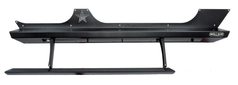


1 JEEP JK4 STEP SLIDER INSTALLATION BD-SS-200-JK4 / BD-SS-201-JK4 Installaton Instructon RSEI 106

2 P A R TS L IST QTY DESCRIPTION 1 Drivers Side Slider Assembly 1 Passenger Side Slider Assembly 1 Wiring Harness and Fuse 1 Double Sided Sticky Squares and Alcohol Pad 1 Cut Off Switch 1 Anti-Seize Packet 1 Control Box 2 Aluminum Spacers 2 Large Washers 2 Grip Tape Strips 2 130mm Bolts 4 Actuating Magnets and Door Sensors 10 5/16 Washers 10 Aluminum Nutserts 10 5/16 SS Button Head Bolts 10 5/16 Stainless Steel Washers *Optonal: 2 LED Light Strips *If any parts listed are missing or damaged please call Rock-Slide prior to installaton TURN OFF YOUR STEP SLIDERS WHILE WHEELING TO PREVENT DAMAGE
 4) DO NOT REMOVE THESE BOLTS!")
 D O N OT completely tighten the bolts, but leave them loose to reflect the same looseness of the 2 rear bolts so you can")
3 STEP SLIDER INSTALLAT ION 1) Remove the stock rocker guards if equipped 2) R em o v e the front body bolts on the driver and passenger side (under the front door) 3) L oosen the rear body bolts (under rear passenger doors) 4) DO NOT REMOVE THESE BOLTS! You will need these bolts to support the slider you are about to put into place on the Jeep REAR FRONT 5) Replace the front body bolts on the driver and passenger sides with the 130mm bolt, aluminum spacer, and large washer in same sequence as the picture below indicates a) D O N OT completely tighten the bolts, but leave them loose to reflect the same looseness of the 2 rear bolts so you can fit the slider forks into these slots 6) Move the slider into it s position on the Jeep a) You may want some help so that you can support the weight of the slider b) Take extra care when positioning the slider on the Jeep to prevent any scratching or marring of the painted surface
 T i g h t en all b ody mo u n t b ol t s to help bring the slider into position on the Jeep 10) This will be the final position of the slider so verify it s")
4 7) Insert the 3 slider forks into the 3 body mount bolt slots a) The slider should fit tight to the Jeep s rocker side 8) The top side of the slider should be at a flat 90 degree angle even with the front and rear wheel wells of the Jeep 9) T i g h t en all b ody mo u n t b ol t s to help bring the slider into position on the Jeep 10) This will be the final position of the slider so verify it s straight, level, even on both sides and you are satisfied with the slider s layout 11) Carefully drill a 7/32 pilot hole into the center of the holes on the slider into the Jeep s rocker side **Word from a mechanic: I found that a 3-step drilling procedure worked best. First lightly center punch, then use an 1/8th inch drill for the first pilot hole. All drills tend to walk so the first drill should be small enough to not walk out of the center punch s dimple. After this the sliders can be removed. The next drill size can be your recommended 7/32 but for the life of me I can t figure out what s so critical with this size other than it should be considerably smaller than the finish size of the 17/32 hole. The relatively large final size makes it hard to drill cleanly with a hand drill in the thin metal of the body panel. For those not experienced with this, the drill will tend to draw itself into the hole and stall once it goes through. a) The body sides are very thin metal so let the drill bit do the work. Don t push too hard on the drill or possible sheet metal damages may occur 12) Loosen the body mount bolts and remove the slider from the Jeep a) You may want some help so that you can support the weight of the slider 13) From the center of the pilot hole, step up the hole size using a 17/32 bit to create a finish hole that will be used to install the nutserts 14) Install 5 nutserts per side in the holes that were just drilled into the body of the Jeep a) We suggest using a crimping tool to optimize the integrity of the nutserts to support the slider 15) If no crimping tool is available, follow these instructions a) Install by using a 5/16 x1.125 minimum length bolt with a 3/8 nut b) Put a small amount of grease on the bolt to reduce friction c) Hold the nut steady with an end wrench so the flange of the insert is flush against the body panel d) Tighten the bolt against the nut to crimp the nutsert into place e) If the nutsert is rotating, place a star-lock washer between the 3/8 nut and nutsert f) Once the nutsert is crimped into place completely back out the bolt g) If the nutsert ever breaks loose and spins, repeat the process and crimp it tighter to prevent spinning
5 (Nutserts that have been installed correctly)
 Attach the slider to the rocker face using the 5/16 button head bolts & washers 19) Start from the center of the slider and work out towards the ends 20)")
6 16) Lift the slider into its final position by inserting the 3 forks on the slider onto the 3 body mount bolts and aligning it against the Jeep rocker face 17) Make sure the actuator wire is free from being pinched between the frame 18) Attach the slider to the rocker face using the 5/16 button head bolts & washers 19) Start from the center of the slider and work out towards the ends 20) Apply a small amount of anti-seize to the threads of each bolt 21) You will be using 5 bolts/washers per side a) We recommend tightening the button heads by hand to prevent any damage to the head of the bolt 22) Tighten the body mount bolts beneath the Jeep to fully secure the slider 23) Make sure the spacer is in between the body and the slider on the front body mount 24) The body mount bolts need to be S N U G to the Jeep frame but D O N OT O V ER TI G HTEN the body mount bolts. Over tightening these bolts could create a friction point causing the slider to not operate optimally 25) Double check all bolts to verify components and hardware are installed correctly and securely to the Jeep ***Please note: Expect some variance in parts that may require you to adjust the tension of bolts to make parts fit correctly and properly. Once all parts are installed, we suggest then fully tightening all bolts again to fit securely*** If you have any questions please contact Rock-Slide WI R I NG HA R NE S S I N S TALL Step Slider Wiring Diagram D r i v e r S ide W ire Color P as s e n g er S ide W ire Color Front Door Sensor Orange/Yellow Front Door Sensor Green/Gray Rear Door Sensor Orange/Purple Rear Door Sensor Blue/White Driver LED Light Brown/Tan Passenger LED Light Pink/Tan Driver Actuator Red/Black Passenger Actuator Red/Black

7 **WARNING** R E M O V E F U S E FROM WIRING HARNESS PRIOR TO INSTALLATION! CONNECTING THE HARNESS TO THE POWER SOURCE WITH THE FUSE ATTACHED WILL SHORT OUT THE WIRING HARNESS NE VE R A L L OW THE DOOR SENSOR TO COME INTO DIRECT CONTACT WITH THE ACTUATING MAGNET. THIS WILL DESTROY THE SENSOR MAKING IT UNUSABLE Remove the B pillar covers on both driver and passenger and driver sides Roll the carpet back underneath the rear seat to expose the floor boards Position the control box under the rear seat on the passenger side It s recommended that you mount the control box under the rear passenger seat because it s out of sight and in a secure location so it will not come into contact with anything or be kicked by a rear seat passenger (see below) Plug the harness into the control box and lay the harness wire into position in the Jeep starting on the rear passenger side You will want to divide the harness between the rear seats, the front passenger seat and finish with the driver door. This will reveal how you will be able to conceal the harness under the carpet when you're done. Once the harness is positioned in its proposed layout you will need to gain access to the slider outside the Jeep to power the slider. Starting on the r ear pa s s e n g er s id e, locate the drain plug and drill a small hole into it to allow you to run the actuator wires to the slider (see below) Once the actuator is run to the slider you can put some silicon sealant around the drilled hole to prevent any elements from entering, but it s not required


8 Route the actuator wire a r ou n d t he b ac k side of the slider and plug the passenger side red/black connector into the slider Actuator wire must be wired around the backside of slider so it s protected from the elements and will not be severed off during off-road activity Secure wires to minimize slack so they are protected. We recommend pulling the excess back through the hole and storing it under the carpet for protection. *Optional: The pink/tan wire is used if LED light package is being installed. Run these wires down the same hole you ran the actuator wire and and finish installing later. Inside the Jeep, route the r e ar p as s e n g e r door sensor wire along the doorframe; and using a sticky pad, mount the sensor underneath the door latch Connect the blue/white wire to the door sensor Place a small piece of electrical tape on the sensor wire to secure (see below) While moving to the fro n t p as s e n g er d oo r, run the harness along the side of the Jeep s tub and route the front passenger door sensor wire up the B pillar of passenger door; and using a sticky pad, mount the sensor underneath the door latch Connect the green/grey wire to door sensor Place a small piece of electrical tape on the sensor wire to secure Returning to the backseat, locate the drain plug on the rear driver side and drill a small hole into it to allow you to run the actuator wires to the slider Once the actuator is run to the slider you can put some silicon sealant around the drilled hole to prevent any elements from entering, but it s not required Route the actuator wire a r ou n d t he b ac k side of the slider and plug the driver side red/black connector into the slider Actuator wire must be wired around the backside of slider so it s protected from the elements and will not be severed off during off-road activity Secure wires to minimize slack so they are protected. We recommend zip ties *Optional: The brown/tan wire is used if LED light package is being installed


9 Route the rear driver door sensor wire along the doorframe; and using a sticky pad, mount the sensor underneath the door latch Connect the orange/purple wire to the door sensor on the rear door Place a small piece of electrical tape on the sensor wire to secure Continue to route the harness wires along the lower doorframe on the tub, and just like performed on the passenger side route the door sensor wire along the B pillar up the doorframe and using another sticky pad, mount the sensor below the door hatch. Connect the orange/yellow wire to the door sensor on the front door Place a small piece of electrical tape on the sensor wire to secure Remove the driver side dash panel and drill a 18mm hole in the panel to accommodate the cutoff switch You can mount the cutoff switch in multiple positions. We recommend the dash panel simply for the ease off access (see below) Mount the ground from the cutoff switch to a metal surface behind dash panel (below) ** THE WIRING SCHEMATIC TO THE BACK OF THE CUTOFF IS RED RED BLACK, IF LIGHT STAYS ON SWAP RED UNTIL.** Route the cutoff switch wires by running the POS+ and NEG- wires up the driver side A pillar and plug them into the back of the cutoff switch Route the remaining POS+ and NEG- wires through the firewall on the driver s side into the engine compartment. Make sure there is NO I N TE R F E R E NCE with any of the pedal linkage under the dash Route these wires along the firewall up to the battery compartment Secure the wires using the harness attached to the firewall Attach the NEG- to the NEG- side of the battery Attach the POS+ to the POS+ side of the battery

10 Position the actuating magnets on the catch side of each door Make sure the actuating magnets are in perfect line with the sensors **D O NOT allow the magnet and sensor to come into direct contact. This will destroy the sensor making it unusable** Once that proper placement is achieved we recommend using a permanent marker to outline the magnet on the door. Re-check all wires to make sure they are completely secure and free from coming into contact with any moving part to prevent system damage due to a cut wire Reinstall all internal plastic and carpet pieces that were removed. Make sure that all wires are tucked back and out of heavy traffic areas on the floor. Route them toward the furthest back area underneath the rear seat Close all doors Insert the fuse into the holder on the POS+ side of the battery Test all doors to make sure the step deploys each time a door is opened, and retracts when the door is closed Thank you for choosing Rock-Slide Engineering products. We value your business and welcome your feedback/suggestions. If you have any concerns please contact us directly at We are here to help you!
JEEP JK4 STEP SLIDER INSTALLATION BD-SS-100-JK4
 JEEP JK4 STEP SLIDER INSTALLATION BD-SS-100-JK4 PARTS LIST QTY DESCRIPTION 1 Drivers Side Slider Assembly 1 Passenger Side Slider Assembly 1 Wiring Harness and Fuse 1 Double Sided Sticky Squares and Alcohol
JEEP JK4 STEP SLIDER INSTALLATION BD-SS-100-JK4
 JEEP JK4 STEP SLIDER INSTALLATION BD-SS-100-JK4 PARTS LIST QTY DESCRIPTION 1 Drivers Side Slider Assembly 1 Passenger Side Slider Assembly 1 Wiring Harness and Fuse 1 Double Sided Sticky Squares and Alcohol
TJ YJ LJ STEP SLIDER INSTALLATION
 TJ YJ LJ STEP SLIDER INSTALLATION BD-SS-100-TJ, BD-SS-100-YJ, BD-SS-100-LJ PARTS LIST QTY DESCRIPTION 1 Drivers Side Slider Assembly 1 Passenger Side Slider Assembly 1 Wiring Harness 1 Double Sided Sticky
Ram Step Slider Installation BD-SS-100-RAM,.BD-SS-101-RAM. Installation Instruction RSEI 108
 Ram Step Slider Installation BD-SS-100-RAM,.BD-SS-101-RAM PARTS LIST DESCRIPTION 1 Drivers Side Slider Assembly 1 Passenger Side Slider Assembly 1 Wiring Harness and Fuse 1 Double Sided S cky Squares and
R-SE JK 4 DOOR Step Slider Install Instructions. *If any parts listed are missing or damages please call prior to install.
 R-SE JK 4 DOOR Step Slider Install Instructions Parts List: 1 Divers side slider assembly 1 Passenger side slider assembly 1 wiring harness 1 control box 2 spacers 2 LED lights (optional) 10 SS Button
ROCK-SLIDE ENGINEERING. Auto Step PART# BD-AS-100-JK4 CONGRATULATIONS ON YOUR PURCHASE OF THE AUTO STEP!
 Auto Step PART# BD-AS-100-JK4 CONGRATULATIONS ON YOUR PURCHASE OF THE AUTO STEP! DESIGNED TO BE FUNCTIONAL, TOUGH, AND DURABLE WHILE PERMITTING YOU TO GET IN AND OUT OF YOUR VEHICLE WITH EASE. IMPORTANT
INSTALLATION MANUAL STEP SLIDER BD-SS-200-JK4. Made in the USA. Front Bracket Middle Bracket Rear Bracket. Tools Required
 Made in the USA INSTALLATION MANUAL STEP SLIDER BD-SS-200-JK4 Description Quantity Electric Step Slider (Pair) 2 Front Bracket Middle Bracket Rear Bracket Bump stop plate with VHB backing 2 Wiring harness
Dodge Cummins Positive Air Shutoff
 1 INSTALL MANUAL 2010-2012 6.7 Dodge Cummins Positive Air Shutoff P/N# 1036722 P/N# 1036722-M UPLEASE READ ALL INSTRUCTIONS BEFORE INSTALLATION An Information decal has been provided in this kit. This
STEP SLIDER MOTOR REPLACEMENT INSTALLATION
 STEP SLIDER MOTOR REPLACEMENT INSTALLATION Important Before installation, make sure control box has a serial number on the circuit board. Updated control boxes all have serial numbers. In order to verify,
Your Legal Fuel Tank Source.
 February 23, 2015 IS# 808 Page 1 of 13 THANK YOU FOR PURCHASING A TRANSFER FLOW 40 GALLON TOOLBOX REFUELING SYSTEM. PLEASE READ THE FOLLOWING PROCEDURES CAREFULLY BEFORE STARTING THE INSTALLATION. CAUTION:
Installation Instructions
 Installation Instructions Jeep JK Unlimited (2007 Present) Mounting Bracket and Air Line System Kit for ARB On-Board Twin Air Compressor (CKMTA12) Made in the USA Kit Contents: 1 Bracket for ARB Compressor
INSTALLATION INSTRUCTIONS
 INSTALLATION INSTRUCTIONS FORCE 10 SPORT R1 REAR DISC CONVERSION KIT A126-50 2005-10 Chevrolet Silverado and GMC Sierra Thank you for choosing STAINLESS STEEL BRAKES CORPORATION for your braking needs.
Ford 7.3L Powerstroke Positive Air Shutoff
 24 October 2012 Ford 7.3L 1999.5-2003 Positive Air Shutoff 1 1999.5-2003 Ford 7.3L Powerstroke Positive Air Shutoff P/N# 1036700 P/N# 1036700-M UPLEASE READ ALL INSTRUCTIONS BEFORE INSTALLATION 24 October
AMP RESEARCH TECH SUPPORT (Press 2) Monday - Friday, 6:00 AM - 5:00 PM PST
 Monday - Friday, 6:00 AM - 5:00 PM PST") APPLICATION AMP Part # Jeep Wrangler Unlimited (JK) 2007 2017 78122-01A (-Door Only) INSTALLATION TIME 3-5 Hours Professional installation recommended SKILL LEVEL 1 2 3 = Experienced TOOLS REQUIRED q 13
APPLICATION AMP Part # Jeep Wrangler Unlimited (JK) 2007 2017 78122-01A (-Door Only) INSTALLATION TIME 3-5 Hours Professional installation recommended SKILL LEVEL 1 2 3 = Experienced TOOLS REQUIRED q 13
I N S T A L L A T I O N G U I D E
 I N S T A L L A T I O N G U I D E APPLICATION AMP Part # Jeep Wrangler Unlimited (JK) 2007 2017 78122-01A (4-Door Only) INSTALLATION TIME 3-5 Hours Professional installation recommended SKILL LEVEL 1 2
GM 6.6L (LML) Duramax Positive Air Shutoff 2.5 CAC TUBES
 Duramax Positive Air Shutoff 2.5 CAC TUBES") 8 April 2013 1036713 GM/Chevy Duramax 2011-2013 (LML) Positive Air Shutoff 1 2011-2013 GM 6.6L (LML) Duramax Positive Air Shutoff 2.5 CAC TUBES P/N# 1036713 P/N# 1036713-M UPLEASE READ ALL INSTRUCTIONS
8 April 2013 1036713 GM/Chevy Duramax 2011-2013 (LML) Positive Air Shutoff 1 2011-2013 GM 6.6L (LML) Duramax Positive Air Shutoff 2.5 CAC TUBES P/N# 1036713 P/N# 1036713-M UPLEASE READ ALL INSTRUCTIONS
2005+ Roll Bar (Mm5RB-20.1 to -20.6) Recommended Center punch 1/8" pilot drill 1-3/4" Hole saw 2" Hole saw
 Recommended Center punch 1/8 pilot drill 1-3/4 Hole saw 2 Hole saw") 3430 Sacramento Dr., Unit D San Luis Obispo, CA 93401 Telephone: 805/544-8748 Fax: 805/544-8645 www.maximummotorsports.com 2005+ Roll Bar (Mm5RB-20.1 to -20.6) Recommended Center punch 1/8" pilot drill
3430 Sacramento Dr., Unit D San Luis Obispo, CA 93401 Telephone: 805/544-8748 Fax: 805/544-8645 www.maximummotorsports.com 2005+ Roll Bar (Mm5RB-20.1 to -20.6) Recommended Center punch 1/8" pilot drill
Stay-IN-Play with Panic Stop Braking
 INSTALLATION INSTRUCTIONS TOWED VEHICLE BRAKING SYSTEM Stay-IN-Play with Panic Stop Braking SMI Manufacturing, Inc. P.O. Box 14040 Evansville, IN 47728 1-800-893-3763 www.smibrake.com SIP0906 Model SIP0603
Installation Instructions
 Installation Instructions Jeep JK 2-Door (2011 Present) Mounting Bracket and Air Line System Kit for ARB On-Board Twin Air Compressor (CKMTA12) Made in the USA Kit Contents: 1 Flat Bracket 1 Formed Bracket
Ford 6.7L Powerstroke Positive Air Shutoff
 8 April 2013 Ford 6.7L 2011-2012 Positive Air Shutoff 1 2011-2012 Ford 6.7L Powerstroke Positive Air Shutoff P/N# 1036703 P/N# 1036703-M UPLEASE READ ALL INSTRUCTIONS BEFORE INSTALLATION BD Engine Brake
GM 6.6L (LLY, LZB, LMM) Duramax Positive Air Shutoff 2.5 CAC TUBES
 Duramax Positive Air Shutoff 2.5 CAC TUBES") 8 April 2013 1036712 GM/Chevy Duramax 2004.5-2010 (LLY,LBZ,LMM) Positive Air Shutoff 1 2005-2010 GM 6.6L (LLY, LZB, LMM) Duramax Positive Air Shutoff 2.5 CAC TUBES P/N# 1036712 P/N# 1036712-M UPLEASE READ
8 April 2013 1036712 GM/Chevy Duramax 2004.5-2010 (LLY,LBZ,LMM) Positive Air Shutoff 1 2005-2010 GM 6.6L (LLY, LZB, LMM) Duramax Positive Air Shutoff 2.5 CAC TUBES P/N# 1036712 P/N# 1036712-M UPLEASE READ
Automatic Roof Hatch Opener
 Automatic Roof Hatch Opener Installation Guide REQUIRED TOOLS (These tools are required to complete the installation) Cordless Drill 1/8 1/4 Drill Bits 1/8 Pin Punch #2 Philips Bit Rachet Sharpie Hammer
INSTALLATION INSTRUCTIONS FUEL SURGE TANK KIT
 INSTALLATION INSTRUCTIONS FUEL SURGE TANK KIT BMW E46 3-Series, Excl Convertible Document: 19-0056 Support: info@radiumauto.com Relieve fuel pressure in vehicle before beginingthe installation. Disconnect
CALIFORNIA TRIMMER MOWER MAINTENANCE MANUAL
 CALIFORNIA TRIMMER MOWER MAINTENANCE MANUAL 2 Table of Contents Section 1: General Information Page Handle Assembly Instructions 4 Maintenance All Models 6 Oil Change Procedures All Models 9 Height Adjustment
INSTALLATION GUIDE. AMP RESEARCH TECH SUPPORT (Press 2) Monday - Friday, 6:00 AM - 5:00 PM PST
 Monday - Friday, 6:00 AM - 5:00 PM PST") INSTALLATION GUIDE APPLICATION AMP Part # Jeep Wrangler Unlimited (JK) 2007 2015 75122-01A (-Door Only) INSTALLATION TIME 3-5 Hours Professional installation recommended SKILL LEVEL 1 2 3 = Experienced
INSTALLATION GUIDE APPLICATION AMP Part # Jeep Wrangler Unlimited (JK) 2007 2015 75122-01A (-Door Only) INSTALLATION TIME 3-5 Hours Professional installation recommended SKILL LEVEL 1 2 3 = Experienced
LPE C5 Battery Relocation Kit
 LPE C5 Battery Relocation Kit The LPE C5 Corvette battery relocation kit improves vehicle weight distribution by moving weight to the rear of the vehicle. The improved weight distribution increases traction
Lethal Performance Dual FPDM Harness Kit Installation
 Lethal Performance Dual FPDM Harness Kit Installation The Lethal Performance Dual FPDM Harness Kit is a plug-and-play modification. Depending on whether you are using the Lethal Performance wire upgrade
Mustang CDC Lightbar (94-04) - Installation Instructions
 - Installation Instructions") Mustang CDC Lightbar (94-04) - Installation Instructions The below installation instructions work for the following products: Classic Design Concepts Mustang Convertible Lightbar (94-04 Carbon Fiber) Classic
Mustang CDC Lightbar (94-04) - Installation Instructions The below installation instructions work for the following products: Classic Design Concepts Mustang Convertible Lightbar (94-04 Carbon Fiber) Classic
Dodge Cummins Positive Air Shutoff
 1998-2002 24V 5.9 Dodge Cummins Positive Air Shutoff (I-00181) 1 INSTALL MANUAL 1998.5-2002 5.9 Dodge Cummins Positive Air Shutoff P/N# 1036719 P/N# 1036719-M UPLEASE READ ALL INSTRUCTIONS BEFORE INSTALLATION
GENUINE PARTS INSTALLATION INSTRUCTIONS
 GENUINE PARTS INSTALLATION INSTRUCTIONS DESCRIPTION: APPLICATION: PART NUMBER: Electronic Tailgate Lock Kit Nissan Titan 999M2-W3005 KIT CONTENTS: Item Qty. Part Description Service Part Number A 1 Electronic
C15C C15C. Page 1 of 20
 2 x Lid Front Hinge 1135 8 x M8 Bolt 8 x M8 Washer (3mm Thick) 4 x M6 Large washers 4 x M6 Spring washers 4 x M6 x 40mm Bolts 6 x M6 20mm Bolts 6 x M6 Washers 20 x Screws 2 x Lid mount gas strut bracket
Installation Instructions
 Installation Instructions Automatic Retracting Running Board Vehicle Application Ford F150 Supercrew 2001-2003 (2004 Heritage) Part Number: 75111-01 www.bestop.com - We re here to help! Visit our web site
Tusk UTV Horn & Signal Kit Installation Instructions
 Tusk UTV Horn & Signal Kit Installation Instructions The Tusk UTV signal kit is designed to be a simple way to provide front and rear turn signals, license plate mount with light, horn, and rearview mirrors
POWERED RUNNING BOARDS INSTALLATION MANUAL
 POWE RUNNING BOARDS INSTALLATION MANUAL Level of Difficulty Moderate Parts List 1 Driver / left running board* 1 Passenger / right running board* 4 Mounting bracket, standard 2 Mounting bracket, middle
Ram 1500 Crew Cab A Ram 2500/3500 Crew Cab A
 I N S T A L L A T I O N G U I D E APPLICATION AMP Part # Ram 1500 Crew Cab 2013-2015 77138-01A Ram 2500/3500 Crew Cab 2013-2015 77138-01A Note:The application works only on the Crew Cab model Vehicles.
2010 FORD TRANSIT ELECTRONIC CRUISE KIT Part Number:
 General Applicability Recommended Tools Item # Qty. Description 1. 250-2758 1 Cruise Control Module 2. 250-2760 1 Switch Harness 3. 250-2759 1 Main Wiring Harness 4. 250-2771 1 Pedal Interface Harness
Toyota 4RUNNER With/MR Overhead Video
 Toyota 4RUNNER With/MR 2010-10.2 Overhead Video Part Number: 00016-00110; Fit Kit-00110-14, Beige 00016-00120; Fit Kit-00120-14, Gray Accessory Code: ED7 Conflicts: Vehicles without a sunroof Kit Contents:
Combine Cover Manual
 Combine Cover Manual Installation Instructions Page 26 Operating Instructions Page 7 Warranty Page 7 Trouble Shooting Page 8 10 For Big Top Extension Model s: Case I.H. 8010, 8120 Please forward onto Customer
Conflicts. TOYOTA Prius Foglights. Part Number: Accessory Code: LF1. Factory Fog Lights
 TOYOTA Prius 2011- Foglights Part Number: 00016-47401 Accessory Code: LF1 Conflicts Factory Fog Lights Item # Quantity Reqd. Description 1 2 Fog Lamps 2 2 Fog Lamp s bezels 3 1 Switch Assembly 4 1 Fog
Part Number: Code: CL7
 Document # 16.01.00 PIO/DIO Rev. A 06/23/08 TOYOTA YARIS 2008- ELECTRONIC CRUISE CONTROL KIT Part Number: 00016-52030 Code: CL7 Section I Installation Preparation Kit Contents Item # Qty. Description 1.
Hummer H up A Hummer H3T up A. 3-5 Hours INSTALLATION GUIDE INSTALLATION TIME SKILL LEVEL.
 INSTALLATION GUIDE APPLICATION MODEL YR PART # Hummer H3 2006 - up 5116-01A Hummer H3T 2009 - up 5116-01A INSTALLATION TIME 3-5 Hours Professional installation recommended SKILL LEVEL 1 2 3 = Experienced
Ford C4 and C6 Floor Mount Automatic Transmission Shifter Installation Instructions
 Ford C4 and C6 Mount Automatic Transmission Shifter Installation Instructions Building American Quality With A Lifetime Warranty! TOLL FREE 1-877-469-7440 tech@lokar.com www.lokar.com Ford C4 and C6 Mount
INSTALLATION INSTRUCTIONS
 INSTALLATION INSTRUCTIONS POWER FRONT DISC CONVERSION KIT A126-7 1963-66 CHEVY C10 PICKUP NON-POWER FRONT DISC CONVERSION KIT A126-8 1963-72 CHEVY C10 PICKUP Thank you for choosing STAINLESS STEEL BRAKES
INSTALLATION GUIDE. AMP RESEARCH TECH SUPPORT (Press 2) Monday - Friday, 6:00 AM - 5:00 PM PST
 Monday - Friday, 6:00 AM - 5:00 PM PST") INSTALLATION GUIDE APPLICATION AMP Part # Jeep Wrangler Unlimited (JK) 2007 up 75121-01A 2-Door INSTALLATION TIME 3-5 Hours Professional installation recommended SKILL LEVEL 1 2 3 = Experienced TOOLS REQUIRED
INSTALLATION GUIDE APPLICATION AMP Part # Jeep Wrangler Unlimited (JK) 2007 up 75121-01A 2-Door INSTALLATION TIME 3-5 Hours Professional installation recommended SKILL LEVEL 1 2 3 = Experienced TOOLS REQUIRED
LoD Offroad. Jeep JK Door Linked Rear Bumper with Tire Carrier Installation Instructions
 LoD Offroad Jeep JK Door Linked Rear Bumper with Tire Carrier Installation Instructions Please read through the instructions before beginning any part of the installation process. Packaging List: 1-Rear
Installation Guide CLAAS Lexion Combines with 9 inch Elevators
 Installation Guide CLAAS Lexion Combines with 9 inch Elevators 955614_01 4/17 1 Table of Contents System Overview 3 Quick Start Guide 4 Flow Sensor Installation 5 Hydraulic Elevator Adjustment Kit Installation
Thank you for purchasing the Craven Speed FlexPod Complete Gauge Pod Kit For R56, R58, R59, R60 with Refresh Engines (2011+)
") Thank you for purchasing the Craven Speed FlexPod Complete Gauge Pod Kit For R56, R58, R59, R60 with Refresh Engines (2011+) Before You Start Please read instructions completely before installing. These
Thank you for purchasing the Craven Speed FlexPod Complete Gauge Pod Kit For R56, R58, R59, R60 with Refresh Engines (2011+) Before You Start Please read instructions completely before installing. These
Deegan 38 HD Rock Sliders w/ LED Rock Lights (07-18 Wrangler JKU)
") Installation Time: 2-3 Hours Deegan 38 HD Rock Sliders w/ LED Rock Lights (07-18 Wrangler JKU) Note: This kit comes with everything you need to wire the lights with a switch in the cab. However, I recommend
Installation Time: 2-3 Hours Deegan 38 HD Rock Sliders w/ LED Rock Lights (07-18 Wrangler JKU) Note: This kit comes with everything you need to wire the lights with a switch in the cab. However, I recommend
Classic Light Bar Mustang
 Classic Light Bar 2005-2012 Mustang Note: Read installation instructions before starting. Component List: 1 Light Bar Part #110000 1 Driver Side Bracket w/set Screw Part #115003 1 Passenger Side Bracket
Tail lights. Headlights
 Revised December 2014 02-017 Light Kit will fit Yamaha G-Series* installation instructions included: tools needed: 2 Headlights 2 Tail Lights Wiring Harness Screws Straps Hazard Switch Phillips Head Screw
Rostselmash Torum 740
 Note: Indented items indicate parts included in an assembly listed above Quantity by Model Part Name/Description Part Number 740 Combine Kit Torum 740 4100762 1 Threaded Arm Assembly 2000311-2 1 Header
Installation Instructions
 Parts Installation Instructions DESCRIPTION PART # QTY A Alignment Tab PN ESB101 1 B Drill Guide PN ESB102 1 C Actuator Cable Assembly PN ESB103 1 C1 72 Actuator Cable 1 C2 5/16 Jam Nut 1 C3 Star Washer
STEALTH. The MOST Versatile and Easiest To Use Towed Vehicle Braking System available! NEED HELP? Call WARNING
 0 STEALTH The MOST Versatile and Easiest To Use Towed Vehicle Braking System available! INSTALLATION manual NEED HELP? Call - -00-0- Read all instructions before installing or operating the Stealth. Failure
Tusk Pannier Racks. Instructions and information KLR
 1 Tusk Pannier Racks Instructions and information KLR650 2008 + Congratulations on your purchase of the Tusk Pannier Racks. These racks are made to handle extreme adventure riding, but work great for the
INSTALLATION INSTRUCTIONS
 INSTALLATION INSTRUCTIONS FX4 ELITE REAR DISC CONVERSION KITS WITH INTERNAL PARKING BRAKE A110-14, A111-25, A111-29 for FORD 8" & 9" REAR ENDS Thank you for choosing STAINLESS STEEL BRAKES CORPORATION
Toyota Prius Interior Light Upgrade
 Toyota Prius 2012- Interior Light Upgrade Part Number 00016-00095 Accesory Code: IL2 Conflicts Kit Contents Item # Quantity Reqd. Description 1 1 Y Adapter 2 1 Wire harness 3 1 Hardware Kit 4 2 White Light
CAMRY STRIP LED DRL TOYOTA Part Number: Accessory Code: LDRS10. PIO / DIO Rev. A 02/26/13. Doc
 Doc. 02.126.00 TOYOTA CAMRY PIO / DIO Rev. A 2013-02/26/13 STRIP LED DRL Part Number: 00016-32280 Accessory Code: LDRS10 Conflicts - Only works on Camry SE Kit Contents Item # Quantity Reqd. Description
INSTALLATION INSTRUCTIONS
 INSTALLATION INSTRUCTIONS FUEL SURGE TANK INSTALLATION KIT 1999-2006 BMW E46 COUPE Document# 19-0056 Support: info@radiumauto.com Note: This kit was designed for a standard single pump Radium Engineering
Dodge Cummins Positive Air Shutoff
 10 June 2013 1998-2002 24V 5.9 Dodge Cummins Positive Air Shutoff 1 1998.5-2002 5.9 Dodge Cummins Positive Air Shutoff P/N# 1036719 P/N# 1036719-M UPLEASE READ ALL INSTRUCTIONS BEFORE INSTALLATION 10 June
LGT-311L Bumper LED Light Kit EZ-Go RXV Installation Instructions
 LGT-311L Bumper LED Light Kit EZ-Go RXV Installation Instructions Caution: Please read through the instructions carefully. Before starting this project, remove the system s positive and negative connections
2015+ S550 MUSTANG Battery Relocation Kit WR-BTRYRELOKIT-LH WR-BTRYRELOKIT-RH
 2015+ S550 MUSTANG Battery Relocation Kit WR-BTRYRELOKIT-LH WR-BTRYRELOKIT-RH The Watson Racing Battery Relocation Kit is NOT designed to protect you in the case of an accident, and therefore is INTENDED
Installation Instructions PowerBoard Automatic Retracting Running Board
 Installation Instructions PowerBoard Automatic Retracting Running Board Vehicle Application Chevy Silverado/GMC Sierra Extended Cab Diesel 2011 and newer Part Number: 75147-15 Chevy Silverado/GMC Sierra
Chrysler 727, 904, 518 Floor Mount Automatic Transmission Shifter Installation Instructions
 Chrysler 727, 904, 518 Mount Automatic Transmission Shifter Installation Instructions Building American Quality With A Lifetime Warranty! TOLL FREE 1-877-469-7440 tech@lokar.com www.lokar.com Release Button
Applicable to the Following Part Numbers. Notes and Maintenance. Torque Specifications. Metric SAE. Use above torque setting unless otherwise noted
 INSTALLATION MANUAL Level of Difficulty Moderate This is the second first of two of two manuals required to complete this installation. The first second manual manual is is included with with your mounting
Jeep Wrangler Unlimited (JK) 2007 up A 2-Door. 3-5 Hours INSTALLATION GUIDE INSTALLATION TIME SKILL LEVEL. 4= Experienced TOOLS REQUIRED
 2007 up A 2-Door. 3-5 Hours INSTALLATION GUIDE INSTALLATION TIME SKILL LEVEL. 4= Experienced TOOLS REQUIRED") INSTALLATION GUIDE APPLICATION AMP Part # Jeep Wrangler Unlimited (JK) 2007 up 751-01A 2-Door INSTALLATION TIME 3-5 Hours Professional installation recommended SKILL LEVEL 1 2 3 = Experienced TOOLS REQUIRED
INSTALLATION GUIDE APPLICATION AMP Part # Jeep Wrangler Unlimited (JK) 2007 up 751-01A 2-Door INSTALLATION TIME 3-5 Hours Professional installation recommended SKILL LEVEL 1 2 3 = Experienced TOOLS REQUIRED
ROUSH Active IO Exhaust. Installation Instructions P/N: (R LITE) Fastback GT Convertible GT V8
 Fastback GT Convertible GT V8") Installation Instructions P/N: 422128 (R1318-5231LITE) Fastback GT Convertible GT V8 39555 Schoolcraft Rd, Plymouth MI, 48170 800.59.ROUSH ROUSH Active IO Exhaust Installation Instructions P/N: 422128
Installation Instructions P/N: 422128 (R1318-5231LITE) Fastback GT Convertible GT V8 39555 Schoolcraft Rd, Plymouth MI, 48170 800.59.ROUSH ROUSH Active IO Exhaust Installation Instructions P/N: 422128
INSTALLATION MANUAL. Middle. Def tank. Standard. Middle. Standard. Def tank WARNING. Level of Difficulty CAUTION. Parts List.
 INSTALLATION MANUAL 3025101 Level of Difficulty Moderate This is the second first of two of two manuals required to complete this installation. The first second manual manual is is included with with your
RIGGING THE FLIGHT CONTROLS
 RIGGING THE FLIGHT CONTROLS Rigging refers to the installation and adjustment of the rods that move flight surfaces in response to inputs from the controls of the helicopter. These rods are cut to length,
Backside License Plate Mount for Jeep JK Wrangler
 REQUIRED TOOLS 10mm SOCKET 13mm SOCKET 4mm HEX KEY WIRE CRIMPS WIRE STRIPPERS ELECTICAL TAPE SCREW DRIVER KIT CONTAINS BACKSIDE MOUNT LICENSE PLATE BRACKET WITH LEDS PLASTIC PASS-THROUGH GROMMET STAINLESS
Bottom Mount Seat Mount Installation & Wiring Instructions
 E81/E87/E90/E91/E92/F22/F30/F31/F32/F80/F82/F87 (and other cars with the same sliders) Bottom Mount Seat Mount Installation & Wiring Instructions These instructions assume a basic comfort with crimping
INSTALLATION INSTRUCTIONS
 INSTALLATION INSTRUCTIONS FUEL SURGE TANK INSTALLATION KIT 1999-2006 BMW E46 COUPE Document# 19-0056 Support: info@radiumauto.com Note: This kit wasn t designed for a FST-R, but can be accomplished. 1.
INSTALLATION INSTRUCTIONS Mitsubishi Lancer Evolution VIII / IX Fuel Surge Tank Kit Document#
 d INSTALLATION INSTRUCTIONS Mitsubishi Lancer Evolution VIII / IX Fuel Surge Tank Kit Document# 19-0077 Brie Tech Support: info@radiumauto.com CAUTION: Exercise extreme caution when working with the fuel
Part Number: TCA-712SE
 Date: 09.04.2013 TOYOTA CAMRY SE 2012-14 LED DRL Part Number: TCA-712SE Kit Contents Item # Quantity Reqd. Description 1 2 DRL s bezels w/led DRL 2 1 Driver Box 3 1 Harness bag 4 1 User s card 5 1 Cushion
MGB Alternator Conversion Installation Instructions For MGA & 1962 to 1967 MGB
 MGB Alternator Conversion Installation Instructions For MGA & 1962 to 1967 MGB PART# 130-078, 130-088, 130-098 440 Rutherford St. Goleta, CA 93117 1-800-642-8295 FAX 805-692-2525 www.mossmotors.com Scan
Installation Instructions PowerBoard Automatic Retracting Running Board
 Installation Instructions PowerBoard Automatic Retracting Running Board Vehicle Application Chevy Silverado/GMC Sierra Extended Cab 2007 and newer (excluding 2011 Diesels) Part Number: 75123-15 Chevy Silverado/GMC
Go-ped ESR750 / ESR750EX Rear Brake Installation Instructions
 Go-ped ESR750 / ESR750EX Rear Brake Installation Instructions This kit provides all the parts you need to install a rear brake on your ESR750 or ESR750EX. It will not work on an ESR Sport, or other Go-ped
PFadvantage JD 3300/4400/6600/7700; 4420
 Ag Leader Technology Combine Installation JD 33//66/77; 2 Note: Indented items indicate parts included Quantity by Model in an assembly listed above Early Late Part Name/Description Part Number 3 3 6 6
INSTALLATION INSTRUCTIONS JEEP 2011-UP JK SECURITY FULL CONSOLE #274
 INSTALLATION INSTRUCTIONS JEEP 2011-UP JK SECURITY FULL CONSOLE #274 PARTS CHECKLIST Tuffy Console #9 Left Front Mounting Bracket #10 Right Front Mounting Bracket #11 Electronics mounting bracket #12 Divider
Dodge Cummins Positive Air Shutoff
 21 October 2011 1998-2002 24V 5.9 Dodge Cummins Positive Air Shutoff 1 1998.5-2002 5.9 Dodge Cummins Positive Air Shutoff P/N# 1036719 P/N# 1036719-M UPLEASE READ ALL INSTRUCTIONS BEFORE INSTALLATION 21
2010+ Camaro Triple-Threat Wet Nitrous System
 2010+ Camaro Triple-Threat Wet Nitrous System This Installation Guide is to be used with the Ny-Trex Owner s Manual. (Refer to the Owner s Manual for installation tips, safety tips, and precautions) 1.
Powerglide Automatic Floor Mount Shifter Installation Instructions
 Powerglide Automatic Mount Installation Instructions Building American Quality With A Lifetime Warranty! TOLL FREE 1-877-469-7440 (865) 966-2269 FAX (865) 671-1999 tech@lokar.com www.lokar.com Powerglide
Dodge Cummins Positive Air Shutoff
 8 April 2013 2003-2007 5.9 Dodge Cummins Positive Air Shutoff 1 2003-2007 5.9 Dodge Cummins Positive Air Shutoff P/N# 1036720 P/N# 1036720-M UPLEASE READ ALL INSTRUCTIONS BEFORE INSTALLATION 8 April 2013
Installation Instructions PowerBoard Automatic Retracting Running Board
 Installation Instructions PowerBoard Automatic Retracting Running Board Vehicle Application Chevy Silverado/GMC Sierra Extended Cab 2007 and newer (excluding 2011 Diesels) Part Number: 75123-15 Chevy Silverado/GMC
I N S T A L L A T I O N G U I D E
 I N S T A L L A T I O N G U I D E APPLICATION MODEL YR PART # Dodge Ram Regular Cab * 1500 2013-2014 76138-01A REV B Dodge Ram Quad Cab * 1500 2013-2014 76138-01A REV B Dodge Ram Crew Cab 1500 2013-2014
Raxiom Factory GPS Rear Back-up Camera Kit (07-17 Wrangler)
") Raxiom Factory GPS Rear Back-up Camera Kit (07-17 Wrangler) Installation Time: 2.5-3Hrs Tools Required: 7mm Socket & Driver 10mm Socket 10mm Open end wrench Knife / Razor blade Zip-ties Wire Cutters Needle
Raxiom Factory GPS Rear Back-up Camera Kit (07-17 Wrangler) Installation Time: 2.5-3Hrs Tools Required: 7mm Socket & Driver 10mm Socket 10mm Open end wrench Knife / Razor blade Zip-ties Wire Cutters Needle
Part Number: SFR-713. Hardware Bag Contents. General Applicability All models. Conflicts - Fog Lights. Date: SCION FRS LED DRL
 Date: 01.30.2014 SCION FRS 2013-2015 LED DRL Part Number: SFR-713 Kit Contents Item # Quantity Reqd. Description 1 2 DRL s bezels w/led DRL 2 1 Driver Box 3 1 Harness bag 4 1 User s card 5 1 Switch Hardware
Procharger Stage II Intercooled Supercharger System (11-14 GT)
") Procharger Stage II Intercooled Supercharger System (11-14 GT) Installation Time: Approximately one day. Installed on 2012 Mustang GT 5.0/Manual Required Tools 3/8 Socket Set (Standard and Metric) 1/2
Procharger Stage II Intercooled Supercharger System (11-14 GT) Installation Time: Approximately one day. Installed on 2012 Mustang GT 5.0/Manual Required Tools 3/8 Socket Set (Standard and Metric) 1/2
Toyota Tacoma Winch Mount Bumper Installation Instructions Tools Required: Transmission cooler relocation brackets Torque Wrench
 2016-2017 Toyota Tacoma Winch Mount Bumper Installation Instructions Tools Required: Items Included: Small flat head screw driver Winch Mount Ratchet, 10mm, 12mm, 14mm, 17mm & Skid Plate 19mm sockets Transmission
General Information. Notations and Conventions. Compatibility Check. Kit Description. Call-Outs. Part Lists Great Plains Manufacturing, Inc.
 Part Lists Great Plains Manufacturing, Inc. 1 Installation Instructions Loup Shaft Monitor Used with Drill models: Compatible with most 1995 and later, two- and three-box drills with 5 8 -inch square main
ATTENTION. Custom Dynamics UTV Turn Signal Kit Installation Instructions
 Custom Dynamics UTV Kit Installation Instructions We thank you for purchasing the Custom Dynamics UTV LED Kit. Our products utilize the latest technology and high quality components to ensure you the most
Jeep JK Evap Can Relocation Kit P/N ECRK
 (626) Trails1 or (626) 872-4571 Jeep JK Evap Can Relocation Kit P/N ECRK Bill of Materials and Installation Instructions WARNING: If you do not realize that Smoking, Sparks or any Open Flame are a very
RZ3-5K Polaris RZR XP 1000 & 900 Kicker 5 Speaker Audio Kit
 PO H PWER PO 5 O KIT I E D U A S A TS S I R LA R Z R R O SP pg 2 pg 9 pg 13 pg 25 pg 29 Disassembly, Wire and Amplifier Plate Installation Glovebox Subwoofer Installation Kick Panel Speakers Installation
GM Floor Mount Automatic Transmission Shifter Installation Instructions
 GM Mount Automatic Transmission Shifter Installation Instructions Building American Quality With A Lifetime Warranty! TOLL FREE 1-877-469-7440 tech@lokar.com www.lokar.com GM Mount Automatic Transmission
Rekluse Motor Sports. The z-start Clutch CRF 250X. Installation Guide Copyright 2002 Rekluse Motor Sports z-start Revision RMS116 CRF 250X
 Rekluse Motor Sports The z-start Clutch CRF 250X Installation Guide Copyright 2002 Rekluse Motor Sports z-start Revision 3.000 RMS116 CRF 250X 191-216 Manual Revision: 103105 Rekluse Motor Sports, inc.
LGT-312L E-Z-Go TXT Light Bar Bumper Kit Installation Instructions
 LGT-312L E-Z-Go TXT 2014+ Light Bar Bumper Kit Installation Instructions Caution: Please read through the instructions carefully. Before starting this project, remove the system s positive and negative
INSTALLATION INSTRUCTIONS 97 FORD EXPEDITION
 INSTALLATION INSTRUCTIONS 97 FORD EXPEDITION 1. Read the instructions completely and carefully before you begin. Check the kit for proper contents (refer to the part s list and the picture diagrams). Before
Part Name/Description Part Number Quantity Instruction Kit Metalfor Flow Sensor
 NOTE: Indented items indicate parts included in an assembly listed above Part Name/Description Part Number Quantity Instruction Kit Metalfor 4101091 1 Flow Sensor 4001356 1 Deflector plate 2000612-1 1
INSTALLATION INSTRUCTIONS
 INSTALLATION INSTRUCTIONS Accessory Application Publications No. AII 22903-22963 ODYSSEY Issue Date MAY 2002 PARTS LIST Subwoofer Kit: P/N 08A39-EP7-100 Subwoofer 2 Cushion tapes 8 Wire ties (1 not used)
PFadvantage MF 6850/6855; Ideal 9080/9090
 MF 6850/6855; Ideal 9080/9090 Note: Indented items indicate parts included in an Quantity by Model assembly listed above MF Ideal Part Name/Description Part Number 6850 6855 9080 9090 Instruction Kit MF
OEM Cruise Control Installation in GMC/Chevy NBS trucks
 OEM Cruise Control Installation in 99-02 GMC/Chevy NBS trucks May 2008 ~ Rampage_Rick Having just installed factory cruise control in my 00 Sierra, I thought I d share the fun. I followed the steps outlined