Taylorcraft 26cc BNF Assembly Manual
|
|
|
- Homer Nelson
- 6 years ago
- Views:
Transcription

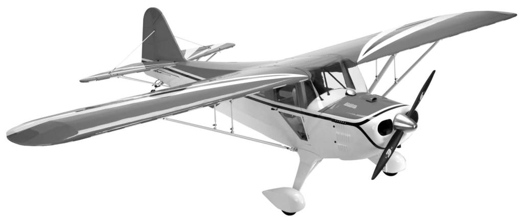
1 Taylorcraft 26cc BNF Assembly Manual TM
2 Notice Table of Contents Introduction Intro...2 The Hangar 9 Taylorcraft 26cc BNF is a gorgeous giant-scale All instructions, warranties and other collateral Product Support...2 recreation of a one-of-a-kind clipped-wing T-Craft that you documents are subject to change at the sole discretion Specifications...2 simply assemble, bind to your 6+ channel DSM2 or DSMX of Horizon Hobby, Inc. For up-to-date product Included Parts Listing...3 aircraft transmitter and fly. It comes out of the box with a literature, visit and click Contents of Kit and Parts Listing...4 Zenoah G26 gas engine, Spektrum AR8000 DSMX receiver on the support tab for this product. Safety Precautions and Warnings...4 and Spektrum A6000 digital servos installed. It even includes Important Information Regarding Warranty...5 a Spektrum 5-cell 2700mAh Ni-MH receiver pack. Using the Manual...5 Meaning of Special Language UltraCote Covering Colors...5 Like the original ARF version, it boasts an impressive list of Transmitter Requirements...5 stunning scale details that include a painted fiberglass cowl, a The following terms are used throughout the product Field Equipment Required...5 detailed cockpit with a full-body pilot figure and painted Pittsstyle wheel pants. And, like the ARF, it is expertly covered in literature to indicate various levels of potential harm Optional Field Equipment...5 when operating this product: Required Tools...5 genuine UltraCote from wing tip to tail. NOTICE: Procedures, which if not properly followed, Required Adhesives...5 Product Support create a possibility of physical property damage AND a Before Starting Assembly...5 little or no possibility of injury. Charging the Receiver Battery...6 Binding Procedure - BNF...6 For technical assistance with this product, please contact the CAUTION: Procedures, which if not properly followed, Landing Gear Installation...7 appropriate Horizon Product Support office. This information create the probability of physical property damage AND a Tail Installation...8 is located in the back of this manual. possibility of serious injury. Tail Wheel Installation...9 Specifications WARNING: Procedures, which if not properly followed, Tail Bracing Installation...11 create the probability of property damage, collateral Engine Installation...14 Wingspan 80.5 in (205cm) damage, and serious injury OR create a high probability Cowling, Propeller and Spinner Installation...16 Overall Length 63.5 in (162cm) of superficial injury. Rudder and Elevator Linkages...18 Interior Installation...19 Wing Area 1152 sq in (74.5 sq dm) Wing Strut Installation...20 Flying Weight lb ( kg) Wing Installation...21 Engine Size Zenoah 26cc (included) WARNING: Read the ENTIRE instruction manual to Center of Gravity...22 Radio 6-channel minimum DSMX or DSM2 become familiar with the features of the product before Control Throws...23 operating. Failure to operate the product correctly can result compatible transmitter Preflight...23 in damage to the product, personal property and cause Range Test Your Radio...23 serious injury. Safety Do s and Don ts for Pilots...24 This is a sophisticated hobby product and NOT a toy. It must Daily Flight Checks...24 be operated with caution and common sense and requires Very Important Regarding your Gasoline Engine...24 some basic mechanical ability. Failure to operate this Product Introduction...24 in a safe and responsible manner could result in injury or Safety Instructions...24 damage to the product or other property. This product is not Support Equipment...25 intended for use by children without direct adult supervision. Operation...25 Do not attempt disassembly, use with incompatible Engine Care and Maintainence...26 components or augment product in any way without the Maintenance Chart...27 approval of Horizon Hobby, Inc. This manual contains Troubleshooting Guide for Gasoline Engines...28 instructions for safety, operation and maintenance. It is Specifications & Technical Data...28 essential to read and follow all the instructions and warnings Engine Warranty Repairs...29 in the manual, prior to assembly, setup or use, in order to Exploded Illustration...30 operate correctly and avoid damage or serious injury. Replacement Parts Listing Airframe Warranty and Repair Policy...32 Compliance Information for the European Union...33 Academy of Model Aeronautics National Model Aircraft Safety Code...34 Engine Warranty Information Hangar 9 Taylorcraft 26cc BNF
3 Included Parts Listing Packaged individually Large Bags Quantity Fuselage with servos, batteries and pushrods (1) Right wing with aileron and servo (1) Left wing with aileron and servo (1) Stabilizer with elevator and hardware (1) Fin with rudder (1) Cowl (1) Pre-assembled landing gear with wheels (1) Pre-assembled left strut (1) Pre-assembled right strut (1) Usage Wings Quantity Usage Wing with strut mounting bracket (2) main wing 4-40 x 1/2-inch button head cap screw (4) strut bracket to wing* Nylon 1/4-20 wing bolts (2) wing to fuselage Clevis pins and keepers (4) wing struts to wing with silicone tubing Fuselage Quantity Usage Fuselage with strut mounting bracket (1) strut mounting bracket* 6-32 x 1/2-inch button head cap screw (4) strut mounting bracket to fuselage* #6 black flat washer (4) strut mounting bracket to fuselage* Clevis pins and keepers (4) wing struts to wing with silicone tubing 4-40 x 1/2-inch button head cap screws (4) cowling to fuselage #4 black nylon flat washers (4) cowling to fuselage Landing gear Quantity Usage Assembled landing gear (1) main landing gear Landing gear cuff (2) main landing gear Wheels, 3-inch (76mm) (2) main wheels* 4mm wheel collar with setscrew (4) wheel to main axle* 4mm axle (2) main wheel axle* 6-32 x 1/2-inch button head cap screw (4) gear spring to main landing gear (2)*and gear spring to fuselage (2) 6-32 x 3/4-inch button head cap screw (4) main landing gear to fuselage #6 flat black washer (6) landing gear to fuselage (4) gear spring strut to landing gear (2)* Wing strut Quantity Usage Assembled strut (right and left) (2) main wing strut 4-40 x 1/2-inch button head cap screw (8) jury strut brace (4)*, strut to wing bracket (4) 4-40 lock nut (8) jury strut brace (4)*, strut to wing bracket (4) #4 black flat washer (8) jury strut brace* Hangar 9 Taylorcraft 26cc BNF Tail bracing Quantity Usage Lower wood strut 10 3 / 4-inch (273mm) (2) front stabilizer to fuselage brace Lower wood strut 10 1 / 2-in (267mm) (2) rear stabilizer to fuselage brace Top wire strut with 3mm threads one-end (2) horizontal stabilizer to fin 3mm threaded rod end (2) horizontal stabilizer to fuselage 4-40 x 1/4-inch button cap screw (6) front/rear bottom strut to fuselage (4); threaded rod ends To brass tabs (2) 4-40 x 5/8-inch button head cap screw (5) horizontal stabilizer to tail strut (4) vertical fin to tail strut (1) #4 black flat washer (6) horizontal stabilizer to tail strut (4) vertical fin to tail strut (2) 4-40 nylon insert lock nuts (7) horizontal stabilizer to bottom struts (4); fuselage to bottom struts (2); vertical fin to top tail strut (1) Brass tabs (2) top strut to horizontal stab (2) Aluminum spreader tab (1) bottom rear strut to fuse Tail wheel Quantity Usage Carbon fiber tail wheel assembly (1) includes 1 1 / 2-inch (38mm) wheel Tail wheel steering spring (2) tail wheel steering Aluminum tiller arm (1) tail wheel steering 2mm x 15mm Phillips wood screw (2) tiller arm to rudder 3mm x 15mm socket head wood screw (2) tail wheel to fuselage #4 black flat washer (2) tail wheel to fuselage Miscellaneous Quantity Usage Wheel pants (right and left) (2) main wheel pants 4-40 x 1/2-inch button head cap screw (4) wheel pants to landing gear #4 black flat washers (4) wheel pants to landing gear Full body pilot figure (1) pilot 2 1 / 2-inch (64mm) aluminum spinner (1) spinner 3/8-inch (10mm) engine standoff (4) engine to firewall 8-32 x 1-inch socket head cap screw (4) engine to firewall #8 black flat washers (4) engine to firewall Pilot seat (1) Painted plywood plate (1) radio cover plate and seat with seat mount 2mm x 10mm washer head wood screws (4) radio tray cover 3/4-inch x 21 5 / 8-inch anodized black tube (1) main wing tube Cable wire ties (4) fuel tubing, kill switch wiring Zenoah 26A Engine (Boxed Separately) (1) engine Evolution 16 x 6 propeller (1) propeller *preinstalled items 3

4 Safety Precautions and Warnings Read and follow all instructions and safety precautions before use. Improper use can result in fire, serious injury and damage to property. Age Recommendation: Not for children under 14 years. This is not a toy Components Use only with compatible components. Should any compatibility questions exist please refer to the product instructions, the component instructions or contact Horizon Hobby, Inc. 1 4 Flight Fly only in open areas to ensure safety. It is recommended flying be done at AMA (Academy of Model Aeronautics) approved flying sites. Consult local ordinances before choosing a flying location Contents of Kit and Parts Listing 7 Propeller Keep loose items that can get entangled in the propeller away from the prop, including loose clothing, or other objects such as pencils and screwdrivers. Especially keep your hands away from the propeller as injury can occur. Replacement Parts Not Shown Batteries 1. HAN Cowl HAN4916 Small Parts Bag 2. HAN Fuselage with Top Hatch* HAN4917 Pushrods Notes on Lithium Polymer Batteries 3. HAN Engine Standoffs for G26 HAN / 2 -inch CNC Spinner When used improperly, lithium polymer batteries are 4. HAN4906 Windshield HAN4563 Wing strut pins with keepers significantly more volatile than alkaline or Ni-Cd/Ni-MH 5. HAN4913 Fin and Rudder batteries used in RC applications. Always follow the 6. HAN4905 Stabilizer manufacturer s instructions when using and disposing of any batteries. Mishandling of Li-Po batteries can result in fire 7. HAN4903 Left Wing Panel* causing serious injury and damage. 8. HAN4904 Right Wing Panel* 9. HAN4909 Stabilizer Strut Parts Small Parts 10. HAN4911 Wing Strut Assembly (left and right)* This kit includes small parts and should not be left 11. HAN4910 Wing Tube unattended near children as choking and serious injury 12. HAN4912 Wheel Pants* could result. 13. HAN4908 Landing Gear* 14. HAN4566 Pilot 15. HAN4902 Top Window 16. HAN4915 Seat and Mounting Panel 17. ZENE26A G26 Air Engine (1.55 cu in) *Items are not preassembled and do not include electronics 18. EVO16060 Evolution Propeller, 16 x 6 4 Hangar 9 Taylorcraft 26cc BNF
5 Safe Operating Recommendations Inspect your model before every flight to make certain it is airworthy. Be aware of any other radio frequency user who may present an interference problem. Always be courteous and respectful of other users of your selected flight area. Choose an area clear of obstacles and large enough to safely accommodate your flying activity. Make certain this area is clear of friends and spectators prior to launching your aircraft. Be aware of other activities in the vicinity of your flight path that could cause potential conflict. Carefully plan your flight path prior to launch. Abide by any and all established AMA National Model Aircraft Safety Code. Important Information Regarding Warranty Please read our Warranty and Liability Limitations in the back of this manual before building this product. If you as the purchaser or user are not prepared to accept the liability associated with the use of this Product, you are advised to return this Product immediately in new and unused condition to the place of purchase. Using the Manual This manual is divided into sections to help make assembly easier to understand, and to provide breaks between each major section. In addition, check boxes have been placed next to each step to keep track of each step completed. Steps with a single box ( ) are performed once, while steps with two or more boxes ( ) indicate the step will require repeating, such as for a right or left wing panel, two servos, etc. Remember to take your time and follow the directions. White True Red Black UltraCote Covering Colors HANU870 HANU866 HANU874 Transmitter Requirements This model requires a minimum of a 6-channel radio to operate all the functions of your aircraft. We suggest the following radio systems available through Horizon Hobby or your local hobby distributor. Spektrum DX6i Spektrum DX8 Spektrum 10T JR DSM2 or DSMX Systems SPMR6610 SPMR8800 Field Equipment Required Fuel (gasoline) 2-cycle oil Ultra fuel pump-manual Double Vision fast field charger Optional Field Equipment PowerPro 12V Starter 12V 7Ah Sealed Battery Self-stick weights, 6 oz Spray cleaner Paper towels Included Components EVOX1001Q HAN155 HAN114 HAN161 HAN102 HAN3626 Spektrum A6000 Servos (6) SPMSA6000 Spektrum AR8000 DSMX Receiver SPMAR8000 Spektrum 2700mAh 6.0V Ni-MH Rx Pack SPMB2700NM Zenoah G26 Air Magneto Engine ZENE26A Zenoah Ignition Kill Switch ZEN20000 Hangar 9 Aluminum CNC 2 1 / 2 -inch Spinner HAN Hangar 9 Fuel Filler with Overflow Fitting HAN116 Evolution 16 x 6 Propeller EVO16060 Required Tools Low-tack tape Needle nose pliers Nut driver: 1/4-inch Phillips screwdriver: #1, #2 Side cutter Open end wrench: 1/4-inch, 12mm, 17mm Hex wrench: 5/64-inch, 3/32-inch, 1/8-inch, 2.5mm, 7/64-inch, 4mm Silicone adhesive Thin CA Threadlock Required Adhesives DEVS250 PAAPT08 PAAPT42 Before Starting Assembly Before beginning the assembly of your model, remove each part from its bag for inspection. Closely inspect the fuselage, wing panels, rudder and stabilizer for damage. If you find any damaged or missing parts, contact the place of purchase. If you find any wrinkles in the covering, use a heat gun (HAN100) and covering glove (HAN150) or covering iron (HAN101) with a sealing iron sock (HAN141) to remove them. Use caution while working around areas where the colors overlap to prevent separating the colors. Note: The hardware to complete each section of the manual is located in the bag with the items required. Leave items in their bags until instructed to open them for use in building your model. Hangar 9 Taylorcraft 26cc BNF 5
 battery.")

6 Charging the Receiver Battery Required Parts Fuselage assembly Receiver charger 1. Open the cockpit door by pulling on the handle. The door is held in position using magnets. Do not rotate the door handle as it will loosen the handle. 2. Connect the charger lead to the connection at the charge jack. The model includes a 2700mAh 5-cell Nickel- Metal Hydride (Ni-MH) battery. Be sure and use a good quality charger. We recommend to cycle the receiver battery 2 3 times prior to flying. CAUTION: Do not use a peak detection charger for the first 2 3 charges of your new Spektrum Ni-MH battery packs. New Ni-MH battery packs may false peak until cycled. The initial charges on your new Spektrum Ni-MH batteries should be done using the Spektrum dual output charger (SPM9550), or other slow chargers of 150 to 300mAh. This charge should be for a period of 24 to 48 hours, or until the battery begins to feel warm to the touch. Subsequent charges may be performed with peak detecting chargers, and at higher rates. Do Not exceed the lower of 1C, or 2000mA. (Example: 1650mAH battery, 1C = 1.65A or 1650mA charge rate) Required Parts Binding Procedure - BNF Fuselage assembly Bind plug Transmitter Binding is connecting a transmitter to an aircraft receiver so the aircraft receiver recognizes the transmitter GUID (Globally Unique Identifier) code. Binding is necessary for proper operation. Your model requires a DSM2 or DMSX full range (high power) transmitter. The list below is Spektrum or JR DSM2/DSMX-equipped full range transmitters and modules that can bind to your model s receiver: Spektrum DX8 Spektrum DX6i JR X9303/ JR 11X JR 12X 2.4/12X MV All SPM Aircraft Module systems List is complete as of this printing. Additional compatible transmitters may be available. 1. Locate the BIND plug. The BIND plug will fit the charge jack in the switch as shown. 2. Follow the procedure as described in your radio manual for binding the receiver and transmitter. Check the operation of the rudder, elevator and throttle servos using the radio system. 6 Hangar 9 Taylorcraft 26cc BNF

 seconds before moving the receiver switch to the on position.")

7 3. Remember to remove the BIND plug from the receiver BEFORE turning off the radio system. Once you have completed binding the transmitter and receiver, unplug the motor battery and remove it from the fuselage. Once you have finished programming your radio, you should re-bind the radio to be sure the fail-safe positions for the servos are correct. Additional Operating Information Before each flight, power on the transmitter and wait about five (5) seconds before moving the receiver switch to the on position. When the receiver is switched on too quickly for the transmitter to make frequency selection, the transmitter and receiver may not connect. When there is no connection, leave the transmitter powered on, turn off the receiver switch then turn it back on to power up the receiver. Required Parts Landing Gear Installation Landing gear assembly Fuselage assembly #4 washer (4) #6 washer (6) Wheel pant (right and left) 6-32 x 1/2-inch button head cap screw (2) 6-32 x 3/4-inch button head cap screw (4) 4-40 x 1/2-inch button head cap screw (4) Required Tools and Adhesives Low-tack tape Threadlock Silicone adhesive Hex wrench: 5/64-inch, 3/32-inch 1. Locate the landing gear and wheel pants as well as the hardware packaged with these items. You will also need the fuselage assembly to attach the gear to. 2. Place the landing gear on the bottom of the fuselage. The gear will angle forward as shown. Slide a #6 washer on each of the four 6-32 x 3/4-inch button head cap screws. Install the screws through the landing gear. Use the included 3/32-inch hex wrench to tighten the screws. Note: Always use threadlock on metal-to-metal fasteners to prevent them from vibrating loose. Hint: A machined hex wrench is helpful to allow the bolts to be tightened and not strip the head of the bolt. Hangar 9 Taylorcraft 26cc BNF 7


 6-32 x 1-inch")


8 3. Slide a #6 washer on each of the two 6-32 x 1/2-inch button head cap screws. Install the screws through the landing gear strut springs, then through the landing gear. Use a 3/32-inch hex wrench to tighten the screws. 5. With the landing gear fairing as close to the fuselage as possible, apply a small amount of silicone adhesive to the plywood inside the landing gear fairing. Slide the fairing tight against the fuselage and use low-tack tape to hold it in position until the adhesive cures. Gluing the fairing to the gear will allow the gear to be removed without damaging the fuselage. Required Parts Tail Installation Fuselage assembly Rudder and fin Stabilizer and elevator #6 washer (4) 6-32 x 1-inch button head cap screw (4) Required Tools and Adhesives Hex wrench: 3/32-inch Thin CA Threadlock 1. Open the bag containing the elevator and stabilizer and the four 4-40 x 1-inch button head cap screws and #4 washers. Also open the bag with the rudder and fin. 4. Attach the wheel pants to the landing gear using four 4-40 x 1/2-inch button head cap screws and four #4 washers. Tighten the screws using 5/64-inch hex wrench. 2. Check that the hinges are glued securely by gently separating the control surface from the fixed surface. If any loose hinges are found, apply thin CA to both sides of the hinge. Allow the CA to soak into the hinge before checking them again. 8 Hangar 9 Taylorcraft 26cc BNF


 3mm x 15mm socket head wood screw (2) Carbon fiber tail wheel assembly with 1 1 / 2 -inch (38mm)wheel")
9 3. Separate the stabilizer halves. Slide the pins and one stabilizer half into the holes in the fin as shown. 4. Slide the remaining stabilizer half into position. Press the stabilizer halves so they fit tightly against the fin as shown. 5. Remove the packaging from the tail of the fuselage. Place the assembly on the fuselage. The fin will fit into the slot along the top of the fuselage. Note: Always use threadlock on metal-to-metal fasteners to prevent them from vibrating loose. 6. Use four 6-32 x 1-inch button head cap screws and four #6 washers to secure the stabilizer to the fuselage. Use a 3/32-inch hex wrench to tighten the screws. Make sure not to over-tighten the screws and damage the underlying structure of the stabilizer. Required Parts Tail Wheel Installation Fuselage assembly Aluminum tiller arm 3mm washer (2) Tail wheel steering spring (2) Aluminum spreader tab 2mm x 15mm Phillips wood screw (2) 3mm x 15mm socket head wood screw (2) Carbon fiber tail wheel assembly with 1 1 / 2 -inch (38mm)wheel Required Tools and Adhesives Hex wrench: 2.5mm Thin CA Phillips screwdriver: #1 Side cutter Needle nose pliers T-pin 1. Open the bag containing the tail wheel assembly and accessories. The fuselage assembly will also be required for this section of the manual. Hint: A machined hex wrench is helpful to allow the bolts to be tightened and not strip the head of the bolt. Hangar 9 Taylorcraft 26cc BNF 9


10 2. Position the tiller arm on the bottom of the rudder so the front edge is aligned as close to the hinge line as possible. Mark the two positions for the mounting screws using a T-pin. 4. Remove the screw and place 2 3 drops of thin CA in each hole to harden the surrounding wood. This will keep the screws from vibrating loose. 6. Use a 2.5mm hex wrench to thread a 3mm x 15mm socket head wood screw into the holes in the bottom of the fuselage for mounting the tail wheel assembly. This will cut threads in the surrounding wood. Remove the screws from the holes. 3. Use a 2mm x 15mm Phillips wood screw and a #1 Phillips screwdriver to make the holes for the two mounting screws in the bottom of the rudder. 5. Use two 2mm x 15mm Phillips wood screws and a #1 Phillips screwdriver to attach the tiller arm to the bottom of the rudder. 7. Place 2 3 drops of thin CA in each hole to harden the surrounding wood. This will keep the screws from vibrating loose in flight. 10 Hangar 9 Taylorcraft 26cc BNF


 4-40 x 1/4-inch button head cap screw (6) 4-40 x 5/8-inch button head cap screw (5) Top wire")
 (2) Required Tools and Adhesives Needle nose pliers Hex wrench: 5/64-inch Nut driver: 1/4-inch")
11 8. Attach the tail wheel assembly and the aluminum spreader tab on the fuselage using two 3mm x 15mm socket head wood screws and two 3mm washers. Tighten the screws using a 2.5mm hex wrench. 9. Connect the arm from the tail wheel to the tiller arm using two tail wheel steering springs. Make a loop on each end of the spring with needle nose pliers. Use care when bending the springs so the tail wheel is aligned with the rudder. Cut the excess spring using side cutters. Required Parts Tail Bracing Installation Fuselage assembly 3mm rod end (2) #4 washer (6) 4-40 locknut (7) Brass tab (2) 4-40 x 1/4-inch button head cap screw (6) 4-40 x 5/8-inch button head cap screw (5) Top wire strut with 3mm threads (2) Rear lower wood strut, 10 1 / 2 -inch (267mm) (2) Front lower wood strut 10 3 / 4 -inch (273mm) (2) Required Tools and Adhesives Needle nose pliers Hex wrench: 5/64-inch Nut driver: 1/4-inch Open-end wrench: 1/4-inch Threadlock 1. Open the bag containing the tail bracing and hardware. The fuselage assembly will also be required for this section of the manual. Hangar 9 Taylorcraft 26cc BNF 11


 strut to the aluminum")


12 2. Measure and mark the front lower wood strut 10 3 / 4 -inch (273mm) and rear lower wood strut 10 1 / 2 -inch (267mm). The longer strut will be used first in the front, then the shorter strut in the rear. 4. Use a 4-40 x 5/8-inch button head cap screw, #4 washer and 4-40 lock nut to attach the strut to the forward hole of the stabilizer. Place the washer on the screw before passing it through the strut so it is between the head of the screw and the stabilizer. Once everything is positioned, use a 1/4-inch nut driver and a 5/64-inch hex wrench to tighten the hardware. Use care not to over-tighten the hardware and damage the underlying structure. 6. Use a 1/4-inch open-end wrench and 5/64-inch hex wrench to attach a 10 1 / 2 -inch (267mm) strut to the aluminum spreader tab. Do not fully tighten the hardware so the strut can be positioned in the following steps. Note: Always use threadlock on metal-to-metal fasteners to prevent them from vibrating loose. 7. Use needle nose pliers to bend the brass tab at about a 30-degree angle. 3. Attach the longer strut to the fuselage and stabilizer. Use a 4-40 x 1/4-inch button head cap screw to secure the strut at the fuselage. Leave the screw finger-tight at this time. 5. Repeat steps 3 and 4 to install the remaining 10 3 / 4 -inch (273mm) strut. Be careful to not induce any warps in the stabilizer when installing the braces. 12 Hangar 9 Taylorcraft 26cc BNF


13 8. The shorter strut can now be attached to the stabilizer using a 4-40 x 5/8-inch button head cap screw, #4 washer, 4-40 lock nut and the brass tab. Make sure the washer is between the stabilizer and brass tab to space the tab slightly away from the structure. Leave the hardware loose so the struts can be positioned. When installing the top wire strut. 10. Thread the 3mm rod end partially on the top wire strut. 13. Adjust the length of the top wire so it just contacts the fin when positioned so the fin is 90 degrees to the stabilizer. 11. Use needle nose pliers to bend the tab of the top wire at about a 30-degree angle as shown. Bolt Washer Washer Nut Strut Strut 9. Repeat steps 6 through 8 to install the remaining short strut. Again leave the hardware loose at this time. Note: Always use threadlock on metal-to-metal fasteners to prevent them from vibrating loose. Note: Always use threadlock on metal-to-metal fasteners to prevent them from vibrating loose. 12. Attach the rod end to the brass tab using a 4-40 x 1/4-inch button head cap screw and a 5/64-inch hex wrench. *Drawing not to scale 14. Repeat steps 10 through 13 for the remaining top wire. Once both wires are set to length, use a 4-40 x 5/8- inch button head cap screw, two #4 washers and a 4-40 lock nut to secure the top wires to the fin. Hangar 9 Taylorcraft 26cc BNF 13
 Engine standoff, 3/8-inch (10mm) (4) 2.")


14 Required Parts Engine Installation Fuselage assembly Engine Cable ties Transmitter Muffler with hardware #8 washer (4) 8-32 x 1-inch socket head cap screw (4) Engine standoff, 3/8-inch (10mm) (4) 2. Use the four aluminum 3/8-inch (10mm) standoffs, four 8-32 x 1-inch socket head cap screws and four #8 washers to attach the engine to the firewall. Use a 1/8-inch hex wrench to tighten the screws. Do not pull the fuel lines too tightly through the nylon tubing clamp or you might kink the fuel tubing between the clamps and the fuel tank. Leave the lower-left bolt loose so the ground can be attached in step Check the alignment of the fin to the stabilizer to make sure they are perpendicular to each other. Also check the alignment between the rudder and fuselage. If not, loosen the hardware slightly to adjust the alignment. Required Tools and Adhesives Needle nose pliers Phillips screwdriver: #1, #2 Threadlock Hex wrench: 1/8-inch, 7/64-inch, 4mm 1. Locate the items to install the engine and muffler to the fuselage. You will also need the fuselage assembly for this section of the manual. 90º 90º 90º 90º 16. Once all the struts and top wires are installed, make sure to check all the hardware to make sure it has been tightened. Note: Always use threadlock on metal-to-metal fasteners to prevent them from vibrating loose. 3. Use side cutters to cut the tie-wrap holding the ignition ground leads and fuel tubing together. 14 Hangar 9 Taylorcraft 26cc BNF


15 4. Check that the ignition switch is in the off position before connecting the leads to the engine in the following step. This will prevent accidentally starting the engine if the propeller shaft is rotated. WARNING: Read and follow all instructions and precautions before use. Failure to do so could result in product malfunction, damage and injury. WARNING: This product can become extremely hot when in use, which could lead to burns. NOTICE: Only use this product with parts specified in the product literature. 7. Connect the fuel line from the T-fitting to the carburetor. Secure the fuel line to the carburetor fitting using a small tie-wrap. Be sure to secure the ignition wire away from the hot cylinder head using a tie wrap. Don t overtighten the tie wrap and deform the wiring or the fuel line on the carburetor inlet. 5. Connect the ignition wire exiting the firewall to the lead from the engine. The two will plug together with mating connectors. Place the ground lug under the washer between the washer and the engine mount. Tighten the bolt using a 1/8-inch hex wrench. Use a cable wire tie to secure the leads so they don t interfere with the muffler. Note: Always use threadlock on metal-to-metal fasteners to prevent them from vibrating loose. 6. Route the ignition wire behind the engine to keep it from contacting the engine. Secure the muffler to the engine using the hardware included with the muffler. Use a #2 Phillips screwdriver and 4mm hex wrench to tighten the hardware to secure the muffler to the engine. Hint: The use of high-temperature exhaust manifold sealant is helpful to help keep the manifold from leaking over time. Note: Check the muffler bolts frequently to be sure they are not getting loose. If you heat up the engine and then tighten the bolts down when hot, the bolts will stay secure longer. Note: Be sure and keep the fuel line and wiring away from the HOT exhaust muffler. 8. Remove the tubing from the choke shaft of the engine. You may need to use a hobby knife and #11 blade to cut the tubing so it can be removed. Hangar 9 Taylorcraft 26cc BNF 15


 Aluminum spinner with backplate and hardware Required Tools and Adhesives Wrench: 1/2-inch, 14mm Hex wrench: 5/64-inch, 4mm Threadlock 1.")

16 9. Thread the screw into the nylon arm included with the engine. 10. Install the included nylon choke arm on the brass shaft of the carburetor. Be sure the arm can rotate fully and does not hit the engine cylinder. Access the arm by reaching through the front cowl opening inlet with your finger or a small piece of wire with a hook on the end (not supplied). Tighten the screw in the arm using a 7/64-inch hex wrench. 11. Connect the ball link to the carburetor arm. The pushrod should slide easily as it is not connected to the throttle servo. Use needle nose pliers to snap the ball link on the ball. Hint: Remove the idle limit setscrew as you will adjust the idle from your transmitter using the throttle trim. 12. Center the throttle stick and trim. With the radio system on, connect the servo arm to the throttle servo using the hardware from the servo and a #1 Phillips screwdriver. Make sure the servo arm is installed perpendicular to the servo center line as shown. Required Parts Cowling, Propeller and Spinner Installation Fuselage assembly Cowling Propeller, 16 x 6 #4 nylon washer (4) 4-40 x 1/2-inch button head cap screw (4) Aluminum spinner with backplate and hardware Required Tools and Adhesives Wrench: 1/2-inch, 14mm Hex wrench: 5/64-inch, 4mm Threadlock 1. Locate the items to attach the cowling to the fuselage. You will also need the fuselage assembly for this section of the manual. 2. Connect the fuel line that comes directly from the fuel tank to the vent fitting on the bottom of the cowl. This is the line not connected to the T-fitting. 13. Check the operation of the throttle using the radio system. It may be necessary to change the travel adjust at the radio to prevent the servo from binding at high- and low-throttle. Make sure when the throttle is at idle the butterfly in the carburetor is closed. 16 Hangar 9 Taylorcraft 26cc BNF


17 3. Remove the plug for the fill line from the cowl. While guiding the cowl on the fuselage, guide the line from the T-fitting through the fill line in the cowl. 5. Insert the plug into the fuel line. The line can now be placed in the fitting. Use this to fill the fuel tank at the field. When the fuel line is inside the cowl, make sure it is not contacting the engine, which could cause it to melt. Important: Always balance your propeller. An unbalanced propeller can cause vibrations to be transmitted into the airframe, which could damage the airframe or other components as well as produce unwanted flight characteristics. 7. Slide the propeller and washer on the engine shaft. Position the propeller with the engine turned counterclockwise into compression with the propeller at approximately between two o clock and eight o clock positions. Use the large nut included with the spinner and a 1/2-inch wrench to tighten the nut. 4. Guide the cowl into position. The holes in the cowl will line up with the holes in the fuselage. Use four 4-40 x 1/2-inch button head cap screws and four #4 nylon washers to secure the cowl. Tighten the screws using a 5/64-inch hex wrench. 8. Thread the spinner adapter on the engine shaft. While holding the larger nut with a 1/2-inch wrench, use a 14mm wrench to tighten the adapter nut against the first nut. 6. Remove the nut and washer from the engine propeller shaft. Slide the propeller backplate on the engine shaft. Note: The included velocity stack for the G26 is not being used as the carburetor is completely enclosed inside the cowling. Hint: A small dot of canopy glue on the threads of the screws will help to stop them from coming loose from vibration. Hangar 9 Taylorcraft 26cc BNF 17


18 9. The spinner can now be attached using the screw provided and a 4mm hex wrench. Make sure the spinner does not contact the propeller when it is installed. Rudder and Elevator Linkages Required Parts Fuselage assembly Required Tools and Adhesives Needle nose pliers Transmitter 1. Turn on the radio and check the operation of the servos. Make sure that both elevator servos are working and moving in the same directions. You will need to use a computer radio to mix the elevator channel to the AUX2 channel for the elevators. You will also need to set up dual ailerons or flaperons to operate the two separate aileron servos. Note: When setting up the mixing for your radio, make sure to disable the switches for the flaps and the AUX2 channels so they don t change the control surfaces if they are moved accidentally. Servo reversing Settings Before setting the control throws, check to make sure the servo reversing settings are set as follows: JR 9503, 11X, 12X and Spektrum DX8: Channel number Channel Name Position 1 Throttle Normal 2 Right Aileron Normal 3 Right Elevator Reverse 4 Rudder Reverse 5 N/A N/A 6 Left Aileron Normal 7 Left Elevator Reverse 8 N/A N/A 2. Check to make sure the servo horns are perpendicular to the servos when the sticks and trims on the transmitter are centered. If not, use the sub-trim feature to make sure the servos are centered correctly. *Drawing not to scale 3. Once the servos have been centered, it may be necessary to loosen the 4-40 nut so the clevises can be adjusted. Thread the clevis in or out on the elevator pushrod so when the clevis is connected to the control horn, the control surface is aligned with the fixed surface. Use a ruler to verify the control surface is aligned with the fixed surface. Once centered, slide the clevis retaining over the forks of the clevis to keep it from opening in flight. Center both elevators at this time. Tighten the 4-40 nut against the clevis to prevent it from changing positions in flight. 18 Hangar 9 Taylorcraft 26cc BNF

 Required Tools and Adhesives Phillips screwdriver: #1 Thin CA Hook and loop tape")


19 4. When connecting the clevises to the rudder, make sure there is a light amount of tension on the cables so the rudder has no play at neutral so it will not flutter. Interior Installation Required Parts Fuselage assembly Pilot Pilot seat Painted plywood plate 2mm x 10mm washer head wood screw (4) Required Tools and Adhesives Phillips screwdriver: #1 Thin CA Hook and loop tape or Zap-A-Dap-A-Goo 1. Locate the items to install the interior. You will also need the fuselage assembly for this section of the manual. Rudder and elevator attach clevis to this hole Drawing not to scale Note: Always use threadlock on metal-to-metal fasteners to prevent them from vibrating loose. 5. Once the clevises are connected, use needle nose pliers to tighten the nuts against the clevises to keep them from vibrating and changing positions. 2. Use a #1 Phillips screwdriver to install and remove one of the 2mm x 10mm washer head wood screws in each of the four mounting holes in the fuselage. This will cut threads in the surrounding wood, preparing them for the next step. Hangar 9 Taylorcraft 26cc BNF 19

 Wing strut assembly (right and left) 4-40 x")


20 3. Apply 2 3 drops of thin CA in each of the holes to harden the threads in the surrounding wood. This will make the screws more secure and help prevent them from vibrating loose. 5. Install the seat by attaching the magnet from the seat to those in the painted plywood plate. Required Parts Wing Strut Installation Wing panel (right and left) Wing strut assembly (right and left) 4-40 x 1/2-inch button head cap screw (4) 4-40 lock nut (4) Required Tools and Adhesives Nut driver: 1/4-inch Hex wrench: 5/64-inch 1. Locate the items to attach the wing struts to the wing panels. You will also need the right and left wing panels for this section of the manual. 4. Secure the painted plywood plate in the fuselage using four 2mm x 10mm washer head wood screws and a #1 Phillips screwdriver. Note that the plate will have the single magnet to the front of the fuselage as shown. 6. The pilot comes with a helmet and life jacket that can be removed. Remove these items to make your pilot look like a civilian pilot for your model. 7. Place the pilot in the cockpit of your model. His legs will straddle the fuel tank when installed. Use hook and loop tape or silicone adhesive to secure the pilot in the seat. 2. When installing the wing struts, the airfoil of the strut will match that of the wing when the jury struts are facing toward the fittings on the wing. Use two 4-40 x 1/2- inch button head cap screws and two 4-40 lock nuts to secure the struts to the fittings. Use a 5/64-inch hex wrench and 1/4-inch nut driver to tighten the hardware. 20 Hangar 9 Taylorcraft 26cc BNF

 Transmitter Anodized-aluminum wing tube Wing assembly")


21 Note: Do not over-tighten the hardware that secures the wing struts to the fittings so the struts can be folded in for transport. 3. The jury struts are secured using the clevis pins and keepers. Attach the struts toward the root of the wing. Note the silicone tubing is placed on the pin before its installation. The struts can be left folded in for transportation. Required Parts Wing Installation Fuselage assembly Nylon 1/4-20 wing bolts (2) Transmitter Anodized-aluminum wing tube Wing assembly (right and left) 1. Slide the wing tube into the wing panel as shown. The tube will slide in easily, so don t force it in farther than it will easily slide. Also remove the nylon wing bolt from the wing. 3. Slide the wing panel into position on the fuselage. Make sure to connect the aileron extensions together using the connector fasteners. 4. Slide the wing tight against the fuselage. 4. Repeat steps 1 through 3 for the remaining wing strut installation. 2. Remove the pins, keepers and silicone tubing from the fitting on the fuselage. Note: If the length of the strut is not correct, loosen the nut on the strut end. Adjust the position of the strut end so the hole in the end aligns with the hole in the bracket. Once adjusted, tighten the nut against the end to prevent the end from vibrating and changing position. Hangar 9 Taylorcraft 26cc BNF 21

 location for your model is 3 3 / 4 -inch (95mm) back from the leading edge of the wing as shown.")


22 5. Secure the wing to the fuselage using the nylon wing bolt removed in step 1. Attach the struts to the fitting on the fuselage using two clevis pins and keepers. The strut is attached to the top of the fitting as shown. Note the silicone tubing is placed on the pin before it is installed through the fitting. Center of Gravity An important part of preparing the aircraft for flight is properly balancing the model. CAUTION: Do not inadvertently skip this step! 1. The recommended Center of Gravity (CG) location for your model is 3 3 / 4 -inch (95mm) back from the leading edge of the wing as shown. Mark the location of the CG on the bottom of the wing with a felt-tipped pen. 7. Repeat steps 2 through 6 to attach the remaining wing panel and adjust the aileron. 6. Center the aileron stick and trim on the transmitter. With the radio system on, check that the aileron servo is perpendicular to the servo as best as you can. Use the sub-trim in the radio programming if necessary to adjust the servo arm position. Next, check that the aileron is aligned with the wing as shown. It may be necessary to loosen the 4-40 nut so the clevises can be adjusted. Thread the clevis in or out on the aileron pushrod so when the clevis is connected to the control horn, the control surface is aligned with the fixed surface. Once centered, slide the clevis retainer over the forks of the clevis to keep it from opening in flight. Center both ailerons at this time. Tighten the 4-40 nut against the clevis to prevent it from changing positions in flight. 22 Hangar 9 Taylorcraft 26cc BNF
23 2. When balancing your model, make sure it is assembled and ready for flight with the fuel tank empty. Support the plane upright at the marks made on the wing with your fingers or a commercially available balancing stand. This is the correct balance point for your model. Balancing Stand 3. You should find the CG to be very close with the components installed as shown in this manual. If the nose of your aircraft hangs low, add weight to the rear of the aircraft. If the tail hangs low, add weight to the nose of the aircraft. Stick-on weights are available at your local hobby store and work well for this purpose. After the first flights, the CG position can be adjusted for your personal preference. We have found this model to balance and fly just fine if balanced between 3 5 / 8 to 4 inches (86mm 101mm). Control Throws 1. Turn on the transmitter and receiver of your model. Check the movement of the rudder using the transmitter. When the stick is moved right, the rudder should also move right. Reverse the direction of the servo at the transmitter if necessary. 2. Check the movement of the elevator with the radio system. Moving the elevator stick toward the bottom of the transmitter will make the airplane elevator move up. 3. Check the movement of the ailerons with the radio system. Moving the aileron stick right will make the right aileron move up and the left aileron move down. 4. Use a ruler to adjust the throw of the elevator, ailerons and rudder. Aileron: Note: When measuring the control throws, always measure the throw from the widest part of the control surface. High Rate: Up: 1 1 / 2 -inches 38mm Down: 15/16-inches 24mm Low Rate: Up: 1-inches 25mm Down: 9/16-inches 14mm Elevator: High Rate: Up: 1 1 / 2 -inches 38mm Down: 1 1 / 2 -inches 38mm Low Rate: Up: 1 1 / 8 -inches 29mm Down: 1 1 / 8 -inches 29mm Rudder: High Rate: Right: 3 1 / 4 -inches 83mm Left: 3 1 / 4 -inches 83mm Low Rate: Right: 1 7 / 8 -inches 48mm Left: 1 7 / 8 -inches 48mm These are general guidelines measured from our own 1/4- scale flight tests. You can experiment with higher rates to match your preferred style of flying. Note: Travel Adjust, Sub-Trim and Dual Rates are not listed and should be adjusted according to each individual model and preference. Note: We highly recommend re-binding the radio system once all the control throws are set. This will keep the servos from moving to their endpoints until the transmitter and receiver connect. CAUTION: Do not use a peak detection charger for the first 2 3 charges of your new Spektrum Ni-MH battery packs. New Ni-MH battery packs may false peak until cycled. The initial charges on your new Spektrum Ni-MH batteries should be done using the Spektrum dual output charger (SPM9550), or other slow chargers of 150 to 300mAh. This charge should be for a period of 24 to 48 hours, or until the battery begins to feel warm to the touch. Subsequent charges may be performed with peak detecting chargers, and at higher rates. Do Not exceed the lower of 1C, or 2000mA. (Example: 1650mAH battery, 1C = 1.65A or 1650mA charge rate) Hangar 9 Taylorcraft 26cc BNF 23
24 Preflight Check Your Radio Before going to the field, be sure your batteries are fully charged per your radio s instructions. Charge the transmitter and receiver battery for your airplane. Use the recommended charger supplied with your particular radio system, following the instructions provided with the radio. In most cases, the radio should be charged the night before going out flying. Before each flying session, be sure to range check your radio. See your radio manual for the recommended range and instructions for your radio system. Each radio manufacturer specifies different procedures for their radio systems. Next, run the motor. With the model securely anchored, check the range again. The range test should not be significantly affected. If it is, don t attempt to fly! Have your radio equipment checked out by the manufacturer. Double-check that all controls (aileron, elevator, rudder and throttle) move in the correct direction. Check the radio installation and make sure all the control surfaces are moving correctly (i.e., the correct direction and with the recommended throws). Check all the control horns, servo horns, and clevises to make sure they are secure and in good condition. Range Test Your Radio Before each flying session, and especially with a new model, it is important to perform a range check. It is helpful to have another person available to assist during the range check. If you are using a Spektrum transmitter, please refer to your transmitter s manual for detailed instructions on the range check process. Safety Do s and Don ts for Pilots Consult local laws and ordinances before choosing a location to fly your aircraft. Check all control surfaces prior to each takeoff. Do not fly your model near spectators, parking areas or any other area that could result in injury to people or damage of property. Do not fly during adverse weather conditions. Poor visibility can cause disorientation and loss of control of your aircraft. Strong winds can cause similar problems. Do not take chances. If at any time during flight you observe any erratic or abnormal operation, land immediately and do not resume flight until the cause of the problem has been ascertained and corrected. Safety can never be taken lightly. Do not fly near power lines. Daily Flight Checks 1. Check the battery voltage of the transmitter battery. Do not fly below the manufacturer s recommended voltage. To do so can crash your aircraft. When you check these batteries, ensure you have the polarities correct on your expanded scale voltmeter. 2. Check all hardware (linkages, screws, nuts, and bolts) prior to each day s flight. Be sure that binding does not occur and that all parts are properly secured. 3. Ensure all surfaces are moving in the proper manner. 4. Perform a ground range check before each day s flying session. 5. Prior to starting your aircraft, turn off your transmitter, then turn it back on. Do this each time you start your aircraft. If any critical switches are on without your knowledge, the transmitter alarm will sound a warning at this time. 6. Check that all trim levers are in the proper location. 7. All servo pigtails and switch harness plugs should be secured in the receiver. Make sure the switch harness moves freely in both directions. Notice All instructions, warranties and other collateral documents are subject to change at the sole discretion of Horizon Hobby, Inc. For up-to-date product literature, visit and click on the support tab for this product. Meaning of Special Language The following terms are used throughout the product literature to indicate various levels of potential harm when operating this product: NOTICE: Procedures, which if not properly followed, create a possibility of physical property damage AND a little or no possibility of injury. CAUTION: Procedures, which if not properly followed, create the probability of physical property damage AND a possibility of serious injury. WARNING:Procedures, which if not properly followed, create the probability of property damage, collateral damage, serious injury or death OR create a high probability of superficial injury. WARNING: Read the ENTIRE instruction manual to become familiar with the features of the product before operating. Failure to operate the product correctly can result in damage to the product, personal property and cause serious injury. This is a sophisticated hobby product and NOT a toy. It must be operated with caution and common sense and requires some basic mechanical ability. Failure to operate this Product in a safe and responsible manner could result in injury or damage to the product or other property. This product is not intended for use by children without direct adult supervision. Do not attempt disassembly, use with incompatible components or augment product in any way without the approval of Horizon Hobby, Inc. This manual contains instructions for safety, operation and maintenance. It is essential to read and follow all the instructions and warnings in the manual, prior to assembly, setup or use, in order to operate correctly and avoid damage or serious injury. 24 Hangar 9 Taylorcraft 26cc BNF
25 Very Important Regarding your Zenoah G26 Gasoline Engine Failure to read and follow these instructions before you proceed may result in engine damage and the voiding of your warranty! Introduction Congratulations on purchasing a Zenoah engine. Cared for properly, these high-quality, finely crafted engines will offer many years of reliability. This instruction manual has been developed to ensure optimum performance from the Zenoah engine you have purchased. It s important that the instructions are read thoroughly prior to mounting and running the engine. Safety Warnings WARNING: Model engines produce a substantial amount of power which can create unsafe situations if not used correctly. Always use common sense and observe all safety precautions when operating, handling or performing any procedure involving your engine. Failure to follow safety precautions could result in serious injury and property damage. Always ensure spectators, especially children, are at least 30 feet away when running the engine Always ensure that the propeller is securely attached to the engine shaft and all retaining fasteners are tightened properly before EACH flight. Use of blue threadlock to tighten nuts is advisable. Always keep small parts out of the reach of children as they can be choking hazards Always secure the airplane before powering the engine. Always keep your face and body away from the path of the propeller blades when starting or running your engine. Always stand behind the propeller when making carburetor adjustments. Always wear safety glasses or goggles when starting and running your engine. Always keep your fuel in a safe place well away from sparks, heat or anything that can ignite. Always ensure the aircraft is secure and will not move once the engine is started. Hangar 9 Taylorcraft 26cc BNF Always rebind your transmitter to your receiver(s) after setup and before first flight. Always ensure the throttle failsafe is set to low throttle in your transmitter. Always perform a range check prior to flight. Always cut off the fuel supply (pinch or disconnect the fuel line to the carburetor) or use the throttle linkage to shut off the air in order to stop the engine. Never use hands, fingers, or any other body part to stop the propeller. Never throw any object into a propeller to stop it. Never run the engine in the vicinity of loose small objects, such as gravel or sand, to avoid the propeller uncontrollably throwing such materials. Never wear loose clothing or a loose neckstrap when operating your model engine as these items could become entangled in the propeller. Never have loose objects such as screwdrivers, pencils etc. in your pockets when operating your model engine. These could fall into the propeller. Never allow fuel to come into contact with eyes or mouth. Gasoline and other fuels used in model engines are poisonous. Always ensure gasoline and fuel are stored in a clearly marked container well away from the reach of children. Precautionary Guidelines Always mount the engine securely on a bench mount or high-quality engine mount. Always use the correct size and pitch of propeller for your engine. Refer to Propeller Chart in this manual. Always confirm proper balance of your propeller prior to installation of the engine. Failure to do so could cause damage to the engine and/or the airframe. Always utilize an electric starter to start your engine. Always discard any propeller that is nicked, scratched, cracked or damaged in any way. Always run your model engine in a well-ventilated area. Model engines produce possibly harmful carbon monoxide fumes. Always store your fuel safely in a sealed, water-resistant container. Always store fuel in a cool, dry location. Do not allow fuel containers to come in direct contact with concrete, as the fuel may absorb moisture. Always responsibly discard fuel if there is condensation and/or water inside the fuel container. Never return unused fuel from the fuel tank back into the fuel container. Never attempt to repair or modify a propeller beyond its intended use. Never handle model engines, mufflers and/or tuned pipes until they have had time to cool. They become extremely hot when in use. Support Equipment The following items are not included with your Zenoah engine but are necessary for operation. Fuel Mix gasoline and 2-stroke gas compatible oil at a mixing ratio of 25 40:1. Note: Be sure to use a gasoline-resistant fuel tubing (do not use any silicone rubber tube). Never use any alcohol fuel or alcohol-added fuel as this will damage the rubber part of the carburetor. Manual or Electric Starter For manual starts, a chicken stick is highly recommended. Never use your fingers to start any model engine as you could be injured. If you must handstart a gasoline engine, be sure to protect your hand with a heavily padded glove. There are a variety of heavy-duty electric starters on the market that can be used. 25
RECOMMENDED MOTOR AND BATTERY SET UP
 SPECIFICATION - Wingspan: 6000mm (236.2 in) - Length: 2873mm (113.1 in) - Flying weight: 14-18 kg - Wing area: 219.4 dm2 - Wing loading: 64g/dm2 - Wing type: HQ airfoils - Covering type: Genuine ORACOVER
I n s t r u c t i o n M a n u a l. Instruction Manual SPECIFICATION
 I n s t r u c t i o n M a n u a l Instruction Manual SPECIFICATION - Wingspan: 3200mm (125,9 in) - Length: 1650mm (64,9 in) - Flying weight: 3000gr 3200gr - Wing area: 64.5 dm2 - Wing loading: 46g/dm2
I/C FLIGHT GUIDELINES
 SPECIFICATION - Wingspan: 3500mm (137.8 in) - Length: 1650mm (64.96 in) - Flying weight: 3700-4000 gr - Wing area: 75 dm2 - Wing loading: 49g/dm2 - Wing type: HQ profile - Covering type: Genuine ORACOVER
96in Super Decathlon ARF
 96in Super Decathlon ARF Instruction Manual Specifications Wingspan: 96in (2438mm) Length: 63.5 in (1614mm) Weight: Approx. 13lbs (6.5kg) 1 Dear Customer, Congratulations on your purchase of Super Decathlon
Jackal 50 ARF Assembly Manual
 Jackal 50 ARF Assembly Manual Notice Table of Contents Notice...2 The Jackal 50 ARF is a Mike McConville design capable of All instructions, warranties and other collateral Meaning of Special Language...2
Aviator Pro 120 ARF. Instruction Manual. Specifications
 Aviator Pro 120 ARF Instruction Manual Specifications Wingspan: 110 in (2800 mm) Length: 74 in (1870 mm) Wing Area: 1581sq in (102 sq dm) Weight: 11.4-13.4 lbs (5190-6100 g) Dear Customer, Congratulations
SIZE.120 OR 30CC SCALE 1:5 ARF
 PC21 PILATUS MK2 SIZE.120 OR 30CC SCALE 1:5 ARF SPECIFICATION - Wingspan: 1772mm (69.72in) - Length: 2019mm (79.5 in) - Flying weight: 6.4-7.2 kg - Wing area: 57.6 dm2 - Wing loading: 113g/dm2 - Wing type:
RECOMMENDED MOTOR AND BATTERY SET UP
 SPECIFICATION - Wingspan: 1404mm (55.3in) - Length: 1134mm (44. 6 in) - Flying weight: 3.2-3.4 kg - Covering type: Genuine ORACOVER - Spinner size: scale type (not included) - Radio: 4 channel minimum
EXTRA 330LX. Specifications: Code: SEA274. Graphics and specifications may change without notice. ASSEMBLY MANUAL
 ASSEMBLY MANUAL EXTRA 330LX Code: SEA274 Graphics and specifications may change without notice. Specifications: Wingspan---------------82.0 in (208.2 cm). Wing area---------------1349.4 sq.in ( 87.1 sq.dm).
Saratoga 40 Assembly Manual
 Saratoga 40 Assembly Manual Specifications Wingspan:... 64.2 in (1630mm) Length:...49.25 in (1251.8mm) Wing Area:...694 sq in (44.77 sq dm) Weight:... 5.5 6.25 lb (2.49 2.83 kg) Radio:...4-channel w/4
1100MM P-51 Mustang ELECTRIC POWERED REMOTE CONTROL AIRPLANE ELEVENHOBBY.COM
 1100MM P-51 Mustang ELECTRIC POWERED REMOTE CONTROL AIRPLANE ELEVENHOBBY.COM WARNING: Read the ENTIRE instruction manual to become familiar with the features of the product before operating. Failure to
Instruction Manual. Specification:
 Instruction Manual L O W Specification: Wingspan: 133 cm (52.3 inches) Length : 104 cm (40.9 inches) Weight : 1790gr Engine : 25-32 two stroke Radio : 4 channel - 4 servo W I N G KIT CONTENTS: We have
51in Aerobatic Series Sukhoi SU-26M Almost-Ready-to-Fly. Instruction Manual. Specifications
 51in Aerobatic Series Sukhoi SU-26M Almost-Ready-to-Fly Instruction Manual Specifications Wingspan: 51.2 in (1300mm) Length: 51.2 in (1300mm) Wing Area: 581 sq in (37.5sq dm) Flying Weight: 3.5 lb (1600g)
Instruction Manual. Wingspan : 2270mm (89.37 inches) : 1870mm (73.62 inches) : 7400gr gr. : 4 channel - 6 standard servo.
 : 1870mm (73.62 inches) : 7400gr gr. : 4 channel - 6 standard servo.") Wingspan : 2270mm (89.37 inches) g Length : 1870mm (73.62 inches) Weight : 7400gr - 7600gr Radio : 4 channel - 6 standard servo Engine : 25cc-35cc KIT CONTENTS: We have organized the parts as they come
Wingspan : 2270mm (89.37 inches) g Length : 1870mm (73.62 inches) Weight : 7400gr - 7600gr Radio : 4 channel - 6 standard servo Engine : 25cc-35cc KIT CONTENTS: We have organized the parts as they come
: 6 channel - 9 servo
 g Wingspan : 2005mm (78.94 inches) Length : 1640mm (64.57 inches) Weight : 6400g - 6600g Engine : 25cc - 35cc Radio : 6 channel - 9 servo KIT CONTENTS: We have organized the parts as they come out of
the leading edge of the wing, at the fuselage - Length: 1540mm (60.6 in) 10% expo; High: 15mm up/down, 10% expo - Wing area: 40dm2
 10% expo; High: 15mm up/down, 10% expo - Wing area: 40dm2") SPECIFICATION - Gravity CG: 165-170 mm (6.5-6.7 in) Back from - Wingspan: 1400mm (55.1 in) the leading edge of the wing, at the fuselage - Length: 1540mm (60.6 in) - Control throw Ailerons: Low: 12mm up/down,
SPECIFICATION - Gravity CG: 165-170 mm (6.5-6.7 in) Back from - Wingspan: 1400mm (55.1 in) the leading edge of the wing, at the fuselage - Length: 1540mm (60.6 in) - Control throw Ailerons: Low: 12mm up/down,
RECOMMENDED MOTOR AND BATTERY SET UP
 SPECIFICATION - Wingspan: 1410mm (55.5 in) - Length: 1278mm (50.3 in) - Flying weight: 3.2-3.4 kg - Wing area: 41.3 dm2 - Wing loading: 75g/dm2 - Wing type: Naca airfoils - Covering type: Genuine ORACOVER
40 EP Gee Bee Y Scale ARF V2 Instruction Manual Specs:
 40 EP Gee Bee Y Scale ARF V2 Instruction Manual Specs: Wing Span: 40" Overall length: 30" Wing area: 306 sq. in Ready to fly weight: 28~32 oz Motor/Engine: Electric: Uranus-28309 brushless outrunner motor,
AVIATOR 25 ARF Almost Ready-to-Fly
 AVIATOR 25 ARF Almost Ready-to-Fly Instruction Manual Specifications Wingspan: 54.3 in (1380mm) Length: 45.2 in (1150mm) Wing Area: 438 sq in (34sq dm) Flying Weight: 3.8 b (1700g) Dear Customer, Congratulations
Radio control model INSTRUCTION MANUAL PYLON RACING. Wingspan: 1148mm (45.2 ) Radio : 4 channels Engine : two-stroke
 Radio : 4 channels Engine : two-stroke") VQA038 VQA039 Radio control model INSTRUCTION MANUAL MAGIC PYLON RACING Wingspan: 1148mm (45.2 ) Radio : 4 channels Engine :.25 -.32 two-stroke WARNING! This radio control model is not a toy. If modified
VQA038 VQA039 Radio control model INSTRUCTION MANUAL MAGIC PYLON RACING Wingspan: 1148mm (45.2 ) Radio : 4 channels Engine :.25 -.32 two-stroke WARNING! This radio control model is not a toy. If modified
RECOMMENDED MOTOR AND BATTERY SET UP
 SPECIFICATION - Wingspan: 2190mm (86.2 in) - Length: 1907mm (75 in) - Flying weight: 9000-12000 gr - Wing area: 92 dm2 - Wing loading: 98g/dm2 - Wing type: Naca airfoils - Retract gear type: Air-retract
MS:159 ASSEMBLY MANUAL. Graphics and specifications may change without notice.
 ASSEMBLY MANUAL MS:159 Graphics and specifications may change without notice. Specifications: Wing span ----------------------------61.8in (157cm). Wing area -----------------1100.5sq.in (71.0sq dm). Weight
Very Fun & Easy NOTICE
 Very Fun & Easy NOTICE NOTICE All instructions, warranties and other collateral documents are subject to change at the sole discretion of our company. For up-to-date product literature, Visit our website
Instruction Manual. Item No: AL506
 Instruction Manual Item No: AL506 Specifications: Wingspan: 2218mm (87.3 in) Length: 1892mm (74.5 in) Wing Area: 100dm2 (1550 sq in) Flying Weight: 7.3kg (16.1 lbs) Engine(not incl.): 50-60cc Gas Radio(not
Instruction Manual BULLDOG. Wingspan : 1410 mm (55.5in) : 1450 mm (57.1in) : 4900gr gr. Weight. : 6-9 Channel/ 7 servo high torque, 1standard
 : 1450 mm (57.1in) : 4900gr gr. Weight. : 6-9 Channel/ 7 servo high torque, 1standard") Wingspan : 1410 mm (55.5in) Length Weight Radio Engine : 1450 mm (57.1in) : 4900gr - 5600gr : 6-9 Channel/ 7 servo high torque, 1standard : 1.20/ 2 stroke 1.80/ 4 stroke KIT CONTENTS: We have organized
Wingspan : 1410 mm (55.5in) Length Weight Radio Engine : 1450 mm (57.1in) : 4900gr - 5600gr : 6-9 Channel/ 7 servo high torque, 1standard : 1.20/ 2 stroke 1.80/ 4 stroke KIT CONTENTS: We have organized
RECOMMENDED MOTOR AND BATTERY SET UP
 SPECIFICATION - Wingspan: 1800mm (70.8 in) - Length: 1355mm (53.3 in) - Flying weight: 4100-4300 g - Wing area: 51 dm2 - Wing loading: 80g/dm2 - Wing type: Naca airfoils - Covering type: Genuine ORACOVER
: 7 channel - 9 servo, Hi-Torque ( Minimum 6 kg ).
.") g Wingspan : 1820mm (71.65 inches) Length : 1625mm (63.98 inches) Weight : 6900gr Engine : 25cc - 35cc Radio : 7 channel - 9 servo, Hi-Torque ( Minimum 6 kg ). KIT CONTENTS: We have organized the parts
g Wingspan : 1820mm (71.65 inches) Length : 1625mm (63.98 inches) Weight : 6900gr Engine : 25cc - 35cc Radio : 7 channel - 9 servo, Hi-Torque ( Minimum 6 kg ). KIT CONTENTS: We have organized the parts
CONFIGURATION(astro/blaze) REQUIRES #
 REQUIRES #") CONFIGURATION(astro/blaze) Length: 29.1in(740mm) Wing Span: 31.9in / 31.1in(810 / 790mm) Wing Area: 1.61 / 1.53ft²(15 / 14.2dm²) Flying Weight: 21oz(600g) REQUIRES Radio control system with 4 channels(delta-mix.)
CONFIGURATION(astro/blaze) Length: 29.1in(740mm) Wing Span: 31.9in / 31.1in(810 / 790mm) Wing Area: 1.61 / 1.53ft²(15 / 14.2dm²) Flying Weight: 21oz(600g) REQUIRES Radio control system with 4 channels(delta-mix.)
RECOMMENDED EDF AND BATTERY SET UP
 SPECIFICATION - Wingspan: 1150mm (45.3 in) - Length: 1587mm (62.5 in) - Flying weight: 5.0-5.3 kg - Wing area: 40dm2 - Wing loading: 125g/dm2 - Wing type: Naca airfoils - Covering type: Genuine ORACOVER
RECOMMENDED MOTOR AND BATTERY SET UP
 SPECIFICATION - Wingspan: 2000mm (78.7in) - Length: 1544mm (60.7 in) - Flying weight: 3600-3800 gr - Wing area: 66 dm2 - Wing loading: 55g/dm2 - Wing type: Naca airfoils - Covering type: Genuine ORACOVER
MS:183 ASSEMBLY MANUAL. Graphics and specifications may change without notice.
 MS:183 ASSEMBLY MANUAL Graphics and specifications may change without notice. Specifications: Wing span ------------------------------79.9in (203cm). Wing area -----------------1165.6sq.in (75.2sq dm).
Instruction Manual. Wingspan : 1400 mm (55.12 inch) : 1480 mm (58.27 inch) : 5500gr gr. : 6-9 channel/ 8 servo high torque,1 standard
 : 1480 mm (58.27 inch) : 5500gr gr. : 6-9 channel/ 8 servo high torque,1 standard") Wingspan : 1400 mm (55.12 inch) g Length : 1480 mm (58.27 inch) Weight : 5500gr - 6000gr Radio : 6-9 channel/ 8 servo high torque,1 standard Engine : GT 22 OS KIT CONTENTS: We have organized the parts
Wingspan : 1400 mm (55.12 inch) g Length : 1480 mm (58.27 inch) Weight : 5500gr - 6000gr Radio : 6-9 channel/ 8 servo high torque,1 standard Engine : GT 22 OS KIT CONTENTS: We have organized the parts
to fly. Most hardware included and all replacement parts are available.
 Instruction Manual The Thunderbolt P47 was perhaps the greatest of world war II in terms of all round performance and capability Phoenix Model has recreated a 2C - 60 class engine (or 4c 91 class) It was
MARACANA ASSEMBLY INSTRUCTION .40 ARF LOW WING TRAINER RADIO CONTROL MODEL. Every body can fly
 RADIO CONTROL MODEL ASSEMBLY INSTRUCTION MARACANA.40 ARF LOW WING TRAINER Every body can fly VQA085 EP GP You can use both Gas or Electric power Wingspan: 59in.(1520mm) Fuselage length: 48in.(1220mm) Engine:
Instruction Manual. Wingspan : 1884 mm (74.17 in) Length. Weight. Engine. : 4 channels / 5 servo standard. : 1450 mm (57.
 Length. Weight. Engine. : 4 channels / 5 servo standard. : 1450 mm (57.") Wingspan : 1884 mm (74.17 in) Length : 1450 mm (57.09 in) Weight : 4000 gr Engine : 60 two strokes Radio : 4 channels / 5 servo standard KIT CONTENTS: We have organized the parts as they come out of the
Wingspan : 1884 mm (74.17 in) Length : 1450 mm (57.09 in) Weight : 4000 gr Engine : 60 two strokes Radio : 4 channels / 5 servo standard KIT CONTENTS: We have organized the parts as they come out of the
MS:176 ASSEMBLY MANUAL. Graphics and specifications may change without notice.
 ASSEMBLY MANUAL MS:176 Graphics and specifications may change without notice. Specifications: Wing span ------------------------------98.4in (250cm). Wing area ----------------1576.4sq.in (101.7sq dm).
RECOMMENDED MOTOR AND BATTERY SET UP
 SPECIFICATION - Wingspan: 1420mm (55.91 in) - Length: 1370mm (53.94 in) - Flying weight: 2600-2800 gr - Wing area: 41.6 dm2 - Wing loading: 65g/dm2 - Wing type: Naca airfoils - Covering type: Genuine ORACOVER
Instruction Manual book
 book ITEM CODE:BH 115. SPECIFICATION Wingspan : 6,000 mm 236,22 in. Length : 2,740 mm 107,87 in. Weight : 17.5kg 38.5Lbs. Radio : 08 channels. Servo : 07-08 HS-5685MH(HITEC) Battery : 2 Cells-Li-Po 7.4V
1660mm (65.4 in) 1200mm (47.2 in) 2700gr gr 6 channel - 7 servo standard 46/ 2 stroke or 52/ 4 stroke
 1200mm (47.2 in) 2700gr gr 6 channel - 7 servo standard 46/ 2 stroke or 52/ 4 stroke") Instruction Manual CESSNA-46 1660mm (65.4 in) 1200mm (47.2 in) 2700gr - 3000gr 6 channel - 7 servo standard 46/ 2 stroke or 52/ 4 stroke KIT CONTENTS: We have organized the parts as they come out of the
Instruction Manual CESSNA-46 1660mm (65.4 in) 1200mm (47.2 in) 2700gr - 3000gr 6 channel - 7 servo standard 46/ 2 stroke or 52/ 4 stroke KIT CONTENTS: We have organized the parts as they come out of the
8mm EPP Acrocub. Instruction Manual. Specifications
 8mm EPP Acrocub Instruction Manual Specifications Wingspan: 34.6 in (880mm) Length: 31.5 in (800mm) Wing Area: 213.9 sq in (13.8sq dm) Flying Weight: Approx. 9oz (270g) Dear Customer, www.valuehobby.com/8mm-epp-acrocub.html
Instruction Manual book
 Instruction Manual book SPECIFICATION Wingspan : 1,800mm. 70.87 in. Length : 1,350 mm. 53.15in. Weight : 3.6kg. 7.92lbs. Parts Listing required (not included). Glow Engine : 55-61 2 stroke. 91 4 stroke.
Instruction Manual book
 book SPECIFICATION Wingspan : 1,450 mm 57.09 in. Length : 1,200mm 47.24in. Weight : 3.1 kg 6.82 Lbs. Radio : 05 channels. Servo : 07 servos. Engine : 61-75 2 stroke. 91 4 stroke. Made in Vietnam. This
RADIO CONTROL MODEL HURRICANE
 RADIO CONTROL MODEL VQAA040G VQAA040B HURRINE Almost ready to fly SPECIFITIONS Wingspan...63 in. / 161cm Length...50 in. / 129cm Engine...50~60 2T / 70~90 4T Or Electric equivalent. RC Functions: Motor
P-47D-40 Thunderbolt 30cc ARF Assembly Manual
 P-47D-40 Thunderbolt 30cc ARF Assembly Manual Notice All instructions, warranties and other collateral documents are subject to change at the sole discretion of Horizon Hobby, Inc. For up-to-date product
SBACH SCALE 1:4 ½ ARF
 SPECIFICATION - Wingspan: 1663mm (65.5 in) - Length: 1638mm (64.5 in) - Flying weight: 4700-5200 gr - Wing area: 56 dm2 - Wing loading: 85g/dm2 - Wing type: Naca airfoils - Covering type: Genuine ORACOVER
RADIO CONTROL MODEL ASSEMBLY INSTRUCTIONS. Wasp
 RADIO CONTROL MODEL ASSEMBLY INSTRUCTIONS Wasp TRAINER Almost ready-to-fly Wingspan 1520mm Fuselage length 1105mm Engine: 40-46 2T / 52-60 4T Electric Motor: 600-700W Radio: 5 channel / 4-5 servo RC Functions:
ALMOST READY TO FLY. Wing Span in cm. 2
 ASSEMBLY MANUAL ALMOST READY TO FLY MS:X9 Specifications Wing Span --------------------------61.4 in ---------------------------156cm. 2 Wing Area --------------------------606.1 sq.in ------------------
Instruction Manual. Wingspan : 1400mm (55.12 in) : 1370mm (53.94 in) : 2600gr gr. : 4 channel / 5 servo. : / 2 stroke_52-71 / 4 stroke
 : 1370mm (53.94 in) : 2600gr gr. : 4 channel / 5 servo. : / 2 stroke_52-71 / 4 stroke") Instruction Manual 540 Wingspan : 1400mm (55.12 in) g Length : 1370mm (53.94 in) Weight : 2600gr - 2800gr Radio : 4 channel / 5 servo Engine : 46-52 / 2 stroke_52-71 / 4 stroke KIT CONTENTS: We have organized
Instruction Manual 540 Wingspan : 1400mm (55.12 in) g Length : 1370mm (53.94 in) Weight : 2600gr - 2800gr Radio : 4 channel / 5 servo Engine : 46-52 / 2 stroke_52-71 / 4 stroke KIT CONTENTS: We have organized
HERO 3D SCALE 1:6 ARF
 Instruction Manual SPECIFICATION - Wingspan: 1500mm(59 in) - Length: 1410mm (55.5 in) - Flying weight: 2100-2300 gr - Wing area: 58 dm2 - Wing loading: 39g/dm2 - Covering type: Genuine ORACOVER - Gear
RECOMMENDED MOTOR AND BATTERY SET UP
 SPECIFICATION - Wingspan: 2567mm (101in) - Length: 2190mm (86.2 in) - Flying weight: 11-13 kg - Wing area: 101 dm2 - Wing loading: 99g/dm2 - Wing type: Naca airfoils - Covering type: Genuine ORACOVER -
INSTRUCTION MANUAL BOOK
 INSTRUCTION MANUAL BOOK ITEM CODE BH57. SPECIFICATION Wingspan: 1,470 mm. 57.87 in. Length : 1,180 mm. 46.46 in. Weight : 2.7 Kg. 5.94 Lbs. Engine : 46 cu.in 2 stroke. 52 cu.in 4 stroke. Radio : 4 channels.
Table of Contents. Tail Wheel Assembly Installation.. page 01. Stabilizer Installation.. page 02. Fin Installation.. page 03
 Table of Contents Tail Wheel Assembly Installation.. page 01 Stabilizer Installation.. page 02 Fin Installation.. page 03 Elevator and Rudder Hinge Installation.. page 04 Rudder Controls.. page 05 Elevator
Instruction Manual book
 book SPECIFICATION Wingspan : 1,920 mm 75.59 in. Length : 1,560 mm 61.42 in. Weight : 5 kg 11.00Lbs. Radio : 06 channels. Servo : 09 servos. Engine : 120 4 stroke. Made in Vietnam. This instruction manual
Instruction Manual EXTRA 260-EP. 1075mm (42.32 in) 1000mm (39.37 in) 1100gr gr. 4 channel - 4 mini servo. Axi motor 2820
 1000mm (39.37 in) 1100gr gr. 4 channel - 4 mini servo. Axi motor 2820") 1075mm (42.32 in) 1000mm (39.37 in) 1100gr - 1400gr 4 channel - 4 mini servo Axi motor 2820 KIT CONTENTS: We have organized the parts as they come out of the box for better identification during assembly.
1075mm (42.32 in) 1000mm (39.37 in) 1100gr - 1400gr 4 channel - 4 mini servo Axi motor 2820 KIT CONTENTS: We have organized the parts as they come out of the box for better identification during assembly.
RECOMMENDED MOTOR AND BATTERY SET UP
 SPECIFICATION - Wingspan: 1669mm (65.7in) - Length: 1229mm (48.43 in) - Flying weight: 3300-3400 gr - Wing area: 44.2 dm2 - Wing loading: 67g/dm2 - Wing type: Naca airfoils - Covering type: Genuine ORACOVER
F3D-30 ARF ASSEMBLY MANUAL
 F3D-30 ARF ASSEMBLY MANUAL This Manuel is the sole property of Kangke Industrial USA, Inc. Reproducing any part without the consent of Kangke Industrial USA, Inc. is a lawful violation. Kangke Industrial
Instruction Manual MUSTANG P51 - EP. Wingspan : 1377mm (54.21in) : 1180mm (46.46 in) : 2200gr gr. : AXI motor 2826 or 4120
 : 1180mm (46.46 in) : 2200gr gr. : AXI motor 2826 or 4120") Instruction Manual MUSTANG P51 - EP Wingspan : 1377mm (54.21in) g Length : 1180mm (46.46 in) Weight : 2200gr - 2600gr Engine : AXI motor 2826 or 4120 Radio : 4 channel / 4 servos standard KIT CONTENTS:
Instruction Manual MUSTANG P51 - EP Wingspan : 1377mm (54.21in) g Length : 1180mm (46.46 in) Weight : 2200gr - 2600gr Engine : AXI motor 2826 or 4120 Radio : 4 channel / 4 servos standard KIT CONTENTS:
Gent EPP. Before use please read the explanations carefully
 Before use please read the explanations carefully Gent EPP Instruction Manual Specifications Fuselage length 900mm 35in Wingspan 820mm 32in Flying Weight 210 240g with battery Additional Required Equipment
WE GET PEOPLE FLYING T-34
 TM WE GET PEOPLE FLYING T-34 Mentor ASSEMBLY MANUAL Specifications Wingspan:... 57.25 in (1454 mm) Length:... 45 in (1146 mm) Wing Area:... 555 sq in (35.8 sq dm) Weight:... 6 7 lb (2.7 kg 3.2 kg) Radio:...
Please read all instructions carefully before assembly and flight!
 Please read all instructions carefully before assembly and flight! Thank you for purchasing the Mig-15. This model is designed for the intermediate to advanced flyer. The model is receiver ready and includes
Instruction Manual. Wingspan : 1694mm (66.69 in) : 1470mm (57.87 in) : 3200gr gr. : 61 two stroke/ 71 four stroke. : 6 channel / 7 servo
 : 1470mm (57.87 in) : 3200gr gr. : 61 two stroke/ 71 four stroke. : 6 channel / 7 servo") Wingspan : 1694mm (66.69 in) g Length : 1470mm (57.87 in) Weight : 3200gr - 3800gr Engine : 61 two stroke/ 71 four stroke Radio : 6 channel / 7 servo KIT CONTENTS: We have organized the parts as they
Wingspan : 1694mm (66.69 in) g Length : 1470mm (57.87 in) Weight : 3200gr - 3800gr Engine : 61 two stroke/ 71 four stroke Radio : 6 channel / 7 servo KIT CONTENTS: We have organized the parts as they
YAK54 MK2. GP/EP size.120/20cc SCALE 1:4 ¾ ARF. Instruction Manual. version. version
 Instruction Manual GP EP version version GP/EP size.10/0cc SCALE 1:4 ¾ ARF SPECIFICATION - Wingspan: 168 (66.3 in) - Length: 1605mm (63.1 in) - Flying weight: 4700-500 gr - Wing area: 54.7 dm - Wing loading:
Instruction Manual book
 Instruction Manual book SPECIFICATION Wingspan : 1,920 mm 75.59 in. Length : 1,560 mm 61.42 in. Weight : 5 kg 11.00Lbs. Radio : 06 channels. Servo : 09 servos. Engine : 120 4 stroke. Made in Vietnam. JU87-STUKA
Instruction Manual book
 book SPECIFICATION Wingspan : 2,080 mm 81.89 in. Length : 1,680 mm 66.14 in. Weight : 6.2 kg 13.64 Lbs. Radio : 06 channels. Servo : 06 servos. Engine : 30-35 CC Gas(FUJI IMVAC). Made in Vietnam. This
48in Sbach-342. Instruction Manual. Specifications
 48in Sbach-342 Instruction Manual Specifications Wingspan: 48in (1219mm) Length: 46in (1163mm) Wing Area: 471sq in (30.4sq dm) Flying Weight: 1.8-2.0lb (800-900g) Dear Customer, www.valuehobby.com/48in-s342-arf.html
Instruction Manual book
 Instruction Manual book SPECIFICATION Wingspan : 1,920 mm 75.59 in. Length : 1,560 mm 61.42 in. Weight : 5 kg 11.00Lbs. Radio : 06 channels. Servo : 09 servos. Engine : 120 4 stroke. Made in Vietnam. JU87-STUKA
Funtana 125 ARF Assembly Manual
 Funtana 125 ARF Assembly Manual Specifications Wingspan... 69.5 in (1765 mm) Length... 68.5 in (1745 mm) Wing Area...1108 sq in (71.5 sq dm) Weight... 8.0 8.5 lb (3.63 4.03 kg) Engine Size....61 1.20 2-stroke;.90
Neptune Seaplane25 ARF. Instruction Manual. Specifications
 Neptune Seaplane25 ARF Instruction Manual Specifications Wingspan: 1270mm (50in) Length: 1155mm (45.5in) Wing Area: 34.8 sq dm (539.4 sq in) Weight: 1950g (4.30lbs) Product Highlights Removable hatch on
ALMOST READY TO FLY. Wing Span in cm. 2
 ASSEMBLY MANUAL ALMOST READY TO FLY MS: X12 A - B Graphics and specfications may change without notice. Kit features. Specifications Wing Span ------------------------------- 42.7 in ---------------------
Instruction Manual book
 Instruction Manual book SPECIFICATION Wingspan : 1,780 mm 70.08 in. Length : 1,520 mm 59.84 in. Weight : 4.8 kg 10.56 Lbs. Radio : 06 channels. Servo : 09 servos. Engine : 120 4stroke Made in Vietnam.
Instruction Manual. We wish you many enjoyable flights with your plane and once again thank you for your choosing a Phoenix Model product
 Instruction Manual Wing span: 1590mm (626 in) Length: 1100mm (433 in) Weight: 1500gr - 1700gr Motor: AXI 2814/10 or Motor: 500-600 w/ gear box Radio: 4 Channel / 4 servos standar Propeller: 12 x 47 We
Ultimate FX 3D. Assembly Manual
 Ultimate FX 3D Assembly Manual Table of Contents Introduction...2 Specifications...2 Contents of Kit/Parts Layout...3 Required Electronics & Accessories...4 High Power Motor Setup*...4 High Power Outrunner
Instruction Manual book
 Instruction Manual book SPECIFICATION Wingspan : 2,170 mm 85.43 in. Length : 1,760 mm 69.29 in. Weight : 6.3 kg 13.86 Lbs. Radio : 06 channels. Servo : 08 servos. Engine : 45-50CC Gas. Made in Vietnam.
RECOMMENDED MOTOR AND BATTERY SET UP
 SPECIFICATION - Wingspan: 1600mm (63 in) - Length: 1285mm (50.5 in) - Flying weight: 2800-3200 gr - Wing area: 40.1 dm2 - Wing loading: 78g/dm2 - Wing type: Naca airfoils - Covering type: Genuine ORACOVER
Instruction Manual book
 Instruction Manual book ITEM CODE:BH118. SPECIFICATION Wingspan : 1,050 mm 41.34 inches. Length : 950mm 37.4 inches. Weight : 1 kg 2.2 lbs. Radio : 04 channels. Servo : 4 mini servos. Motor : KMS 2814/05
Piper J-3 Cub 40 Plug-N-Play
 Piper J-3 Cub 40 Plug-N-Play ASSEMBLY MANUAL Specifications Wingspan:... 80 in (2032mm) Fuselage length:... 49.9 in (1268mm) Wing area:... 919 sq in (59.3 sq dm) Weight:... 6.75 7.5 lb (3 3.4 kg) Engine:...Evolution.46
Instruction Manual book
 book Item code:bh131 SPECIFICATION Wingspan : 3,000 mm 118.1 in. Length : 1,600 mm 62.99 in. Weight : 2.2 kg 4.84 Lbs. Radio : 05 channels. Servo : 06 mini servos. Electric Motor: BOOST 40 Battery : 3celIs
STICK F Class 60 Class INSTRUCTION MANUAL. Or Electric equivalent. (2T engine) (4T engine) Radio control model SPECIFICATIONS
 (4T engine) Radio control model SPECIFICATIONS") Radio control model 45 Class 60 Class (2T engine) (4T engine) Or Electric equivalent INSTRUCTION MANUAL STICK F - 1500 SPECIFICATIONS Wingspan 60 in. Length 38.5 in. Electric Motor 650 Watt Glow Engine.45
Radio control model 45 Class 60 Class (2T engine) (4T engine) Or Electric equivalent INSTRUCTION MANUAL STICK F - 1500 SPECIFICATIONS Wingspan 60 in. Length 38.5 in. Electric Motor 650 Watt Glow Engine.45
FUN-50 ARF ASSEMBLY MANUAL
 FUN-50 ARF ASSEMBLY MANUAL This Manuel is the sole property of Kangke Industrial USA, Inc. Reproducing any part without the consent of Kangke Industrial USA, Inc. is a lawful violation. Kangke Industrial
Assembly Manual For. Wingspan: 88 in Wing area: sp in Length: 78.8 in Engine: 50CC.
 Assembly Manual For Wingspan: 88 in Wing area: 1479.8 sp in Length: 78.8 in Engine: 50CC www.pilot-rc.com INTRODUCTION Thank you for purchasing our new 50 cc model. We strive to bring you the most complete
Instruction Manual book
 Instruction Manual book ITEM CODE: BH56. SPECIFICATION Wingspan : 1,660 mm 65.35 in. Length : 1,420 mm 55.91 in. Weight : 3.8 kg 8.36 Lbs. Radio : 06 channels. Servo : 08 servos. Engine : 75 Cu.in 2 Stroke.
SK-50 ARF ASSEMBLY MANUAL
 SK-50 ARF ASSEMBLY MANUAL Kangke Industrial USA, Inc. 65 East Jefryn Blvd. Deer Park NY 11729 http://www.kangkeusa.com E-mail: info@kangkeusa.com Tel: 1-877-203-2377 Fax: 1-631-274-3296 Congratulations!
RECOMMENDED MOTOR AND BATTERY SET UP
 Instruction Manual SPECIFICATION - Wingspan: 1418mm (55.8 in) - Length: 1314mm (51.7 in) - Flying weight: 2700-3200 gr - Wing area: 36.8 dm2 - Wing loading: 76g/dm2 - Wing type: Naca airfoils - Covering
(Glider) ASSEMBLY MANUAL
 ASSEMBLY MANUAL") (Glider) MS:132 ASSEMBLY MANUAL Graphics and specifications may change without notice. Specifications: Wing span ------------------------------118.1in (300cm). Wing area ---------------------902.1sq.in
(Glider) MS:132 ASSEMBLY MANUAL Graphics and specifications may change without notice. Specifications: Wing span ------------------------------118.1in (300cm). Wing area ---------------------902.1sq.in
NOTICE. Meaning of Special Language
 Technologies Limited User Manual For Gas Radial Engines NOTICE All instructions, warranties and other collateral documents are subject to change at the sole discretion of UMS, Inc. For up-to-date product
ASSEMBLY MANUAL
 www.seagullmodels.com MS: X104 ASSEMBLY MANUAL Graphics and specifications may change without notice. Specifications: Wing span ----------------- 35.4in (90.0cm). Wing area ------------------392.2sq.in
Instruction Manual book
 Instruction Manual book ITEM CODE: BH39. SPECIFICATION Wingspan : 181 cm 71.26 inches. Length : 155 cm 61.024 inches. Weight : 04 kg 8.8 lbs. Servo : 9 servos. Radio : 6 channels. Engine : 91 cu.in - 2
Please read all instructions carefully before assembly and flight!
 c c Please read all instructions carefully before assembly and flight! Thank you for purchasing the. This model is designed for the intermediate to advanced flyer. The model is receiver-ready and includes
Instruction Manual book
 Instruction Manual book ITEM CODE:BH118. SPECIFICATION Wingspan : 1,050 mm 41.34 inches. Length : 950mm 37.4 inches. Weight : 1 kg 2.2 lbs. Radio : 04 channels. Servo : 4 mini servos. Motor : BL2215/20
MEMO. No.4341 Specification: Wing Span: 29.1 (740mm) Length: 36.6 (930mm) 2. Warranty
 Length: 36.6 (930mm) 2. Warranty") MEMO No.4341 Specification: Wing Span: 29.1 (740mm) Length: 36.6 (930mm) 2 Wing Area: 299 sq.in. (19.29 dm ) Weight: 18.9oz. (536.5g) 2 Wing loading: 0.58 oz./sq.ft (27.8g/dm ) Motor: OBL 29/27-07A Warranty
MEMO No.4341 Specification: Wing Span: 29.1 (740mm) Length: 36.6 (930mm) 2 Wing Area: 299 sq.in. (19.29 dm ) Weight: 18.9oz. (536.5g) 2 Wing loading: 0.58 oz./sq.ft (27.8g/dm ) Motor: OBL 29/27-07A Warranty
Build Manual. Vector & Xtra Slick
 Build Manual Vector & Xtra Slick Warning information this is not a toy! Read and understand entire manual before assembling model Do not overlook the warnings and instructions enclosed or those provide
Instruction Manual book
 Instruction Manual book Item code:bh117 SPECIFICATION Wingspan : 2,100 mm 82.68 in. Length : 1,875 mm 73.82 in. Weight : 7.5 kg 16.5 Lbs. Parts listing required (not included) Radio : 08 channels. Servo
ASSEMBLY MANUAL. Kit features. MS:76
 ASSEMBLY MANUAL MS:76 Graphics and specfications may change without notice. Specifications: Wingspan---------------------------------------------------- 82.8 in------------------------------------- 210.3cm.
PilotRC Trainer USER MANUAL
 PilotRC Trainer USER MANUAL Introduction Thank you for purchasing our Trainer plane. we strive to achieve a good quality quick build ARF aircraft. It requires the least amount of assembly of any ARF kit
Instruction Manual book
 book ITEM CODE:BH 72 SPECIFICATION Wingspan : 2,350 mm 92.52 in. Length : 1,730 mm 68.11 in. Weight : 6.4 kg 14.08 Lbs. Radio : 06 channels. Servo : 08 servos. Engine : OS. GT22-26cc gas. Made in Vietnam.
Instruction Manual book
 Instruction Manual book ITEM CODE:BH135 SPECIFICATION Wingspan : 4,200mm. 163.35 in. Length : 2,100 mm. 82.68 in. Weight : 7,6 kg. 16.72lbs Radio : 07 channels. Servo : 05 06 standard high torque servos,
MS:158 ASSEMBLY MANUAL. Graphics and specifications may change without notice.
 MS:158 ASSEMBLY MANUAL Graphics and specifications may change without notice. Specifications: Wing span ------------------------------70.9in (180cm). Wing area -----------------644.8sq.in (41.6sq dm).
Pitts Challenger m (100cc) MANUAL
 MANUAL") Pitts Challenger 87 2.20m (100cc) MANUAL 1- Introduction: WELCOME TO THE PILOT-RC TEAM! Thank you for choosing a Pilot-Rc plane as your next model. We hope that you enjoy many successful and exhilarating
Pitts Challenger 87 2.20m (100cc) MANUAL 1- Introduction: WELCOME TO THE PILOT-RC TEAM! Thank you for choosing a Pilot-Rc plane as your next model. We hope that you enjoy many successful and exhilarating
MS:136 ASSEMBLY MANUAL. Graphics and specifications may change without notice.
 ASSEMBLY MANUAL MS:136 Graphics and specifications may change without notice. Specifications: Wing span ----------------------------79.5in (202cm). Wing area -----------------965.7sq.in (62.3sq dm). Weight
Instruction Manual book
 book SPECIFICATION Wingspan : 2,310 mm 90.94 in. Length : 1,750 mm 68.90 in. Weight : 8.4 kg 18.48 Lbs. Radio : 06 channels. Servo : 09 servos + 2 mini servos (elevator). Engine : 45-55CC gas. Made in