OPERATORS MANUAL & SPARE PARTS LIST TURF TROOPER
|
|
|
- Katrina Porter
- 6 years ago
- Views:
Transcription


1 OPERATORS MANUAL & SPARE PARTS LIST TURF TROOPER 3


2 K A E B 1 4 H C L 2 5 I D H J G F 3 6 1


3 L M 7 10 J G 8 11 G 9 12 R 2

4 T P Q O C

5 19 21 T
6 CONTENTS Page CERTIFICATE OF CONFORMITY 6 SPECIFICATIONS 7 INTRODUCTION 8 SAFETY INSTRUCTIONS 8 ASSEMBLING THE MACHINE 9 OPERATING THE MACHINE 9 SAFETY INTERLOCK SWITCHES 10 TO START THE ENGINE 10 TO STOP THE ENGINE 10 STEERING 10 WORKING INSTRUCTIONS 10 SPEED CONTROL 10 CYLINDER DRIVE CLUTCH 10 CUTTING WITH THE MACHINE 11 THROTTLE CONTROL 11 BRAKE & PARKING BRAKE 11 LIFTING & LOWERING MOWER UNITS 11 FRONT CYLINDERS 11 REAR CYLINDER 11 MAINTENANCE 11 LUBRICATION 12 ENGINE LUBRICATION 12 MACHINE LUBRICATION 12 BATTERY 12 TYRES 12 ADJUSTMENTS 12 STEERING LINKAGE 12 DRIVE TRAIN ADJUSTMENTS 12 MAIN DRIVE BELT 12 CYLINDER DRIVE BELT ADJUSTMENT 13 CYLINDER CLUTCH DRIVE BELT 13 CYLINDER CLUTCH ADJUSTMENT 13 HEIGHT OF CUT 13 CUTTING CYLINDER TO BOTTOM BLADE 13 TO ADJUST 14 PARKING BRAKE 14 ILLUSTRATED PARTS LISTS 15 MAIN FRAME ASSEMBLY 16 DRIVE ASSEMBLY 18 STEERING ASSEMBLY 22 CUTTING CYLINDER ASSEMBLIES 24 LINKAGE ASSEMBLIES 28 ELECTRICAL ASSEMBLY 30 WIRING DIAGRAM 32 5
7 EC DECLARATION OF CONFORMITY I, the undersigned, of Allen Power Equipment Ltd., The Broadway, Didcot, Oxon OX11 8ES, certify that the machine described below: - Category Make Type Model Cutter Lawnmower ALLEN Ride-on Turf Trooper III 60 (1530mm) Cylinder Comply with the following Directives. 79/113/EEC 89/336/EEC as amended by 92/31/EEC 89/392/EEC 84/538/EEC as amended by 88/180/EEC and 88/181/EEC 2000/14/EC Signed: Peter Bateman Managing Director 6
 3600 SOUND POWER LEVEL (LWA) db(a) 99 SOUND PRESSURE LEVEL (LPA) db(a) 86.")
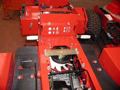
8 SPECIFICATIONS MODEL ENGINE GXV 270 MANUFACTURER Honda POWER HP 8.5 MAX PERMISSIBLE (KW) 6.4 ENGINE SPEED (RPM) 3600 SOUND POWER LEVEL (LWA) db(a) 99 SOUND PRESSURE LEVEL (LPA) db(a) 86.4 EXPLANATION OF SYMBOLS Warning Read Instruction Manual before operating Parking Brake Engaged Disengaged Cutter clutch Engaged Disengage 7
9 INTRODUCTION The ALLEN TURF TROOPER 3 is an advanced ride-on cylinder mower designed to cut grass quickly, efficiently and economically, giving your lawn the velvet finish only a quality cylinder mower can deliver. Attractive styling and a high standard of build along with detailed attention to user comfort and ease of operation combine to produce the ultimate in mowing for the large garden owner. Large wheels and rear wheel steering on the Turf Trooper 3 mean that not only will the machine cope with undulating ground but it has the ability to turn in its own length, making mowing around trees or posts effortless. Pedal control gives totally variable forward and reverse motion thus allowing the exact cutting speed for every mowing application. Six blades on each seven-inch cylinder ensure that the machine leaves a well-manicured look to any lawn. From the moment you turn the key and the engine springs to life until you park the machine and fold the front cylinders for storage, mowing the grass has never been easier. This manual will help you to get to know your Turf Trooper and obtain the best results from it. The Trooper has been designed to the highest standards. With proper care and maintenance it will provide many years of reliable and enjoyable service. PLEASE READ THIS MANUAL THOROUGHLY BEFORE STARTING OR USING YOUR TURF TROOPER 3 SAFETY INSTRUCTIONS Please ensure that the instructions contained in this manual are read carefully and fully understood by any person likely to operate the Trooper. Before starting the engine the operator should check that the drive pedal is in neutral, the drive lever to the cylinder transmission is in the disengaged position and the parking brake is applied. Do not run the engine in a confined space; exhaust gases contain carbon monoxide, which is an odourless and deadly poisonous gas. Before starting the engine, check that the cutting cylinders are free to run with no obstruction present and that they are not blocked with grass or debris from previous use. Make sure all parts are in good working order such as tyres, steering, cutting blades and belts and that all guards are in position. When driving the machine for the first time keep travelling speed low and become familiar with all the controls in an area where there is plenty of room to manoeuvre. When travelling and not wishing to cut grass, ensure all cutting units are lifted and latched into the raised transport position and the cylinder transmission is disengaged. Ensure that the area to be cut is free of all obstructions, which can be removed, such as stones and metal objects. Obstructions, which cannot be removed, should be negotiated carefully to prevent accidental damage to the cutters. If working on slopes or undulating ground be particularly careful and avoid conditions, which may cause the machine to slide. Maximum angles permissible for use are: 15º max. down slope in forward 15º across slope 15º max. up slope in forward 15º max. backing down slope in reverse On damp or uneven ground these angles should be reduced. Start and park the machine on level ground. Before leaving the driving position disengage all drives, set the parking brake and stop the engine. 8
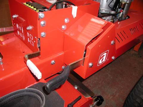
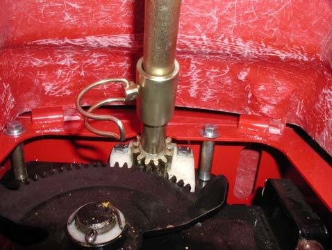
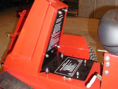
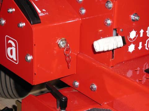
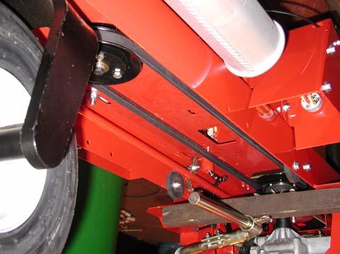
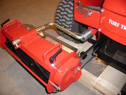
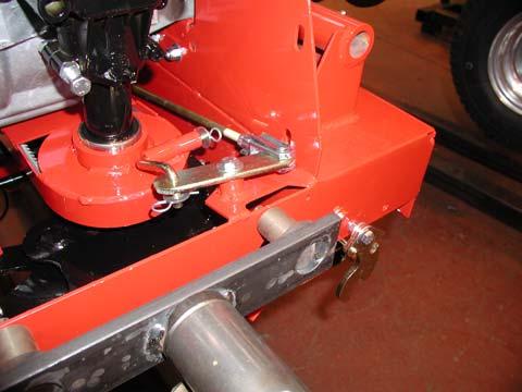
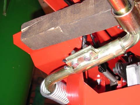
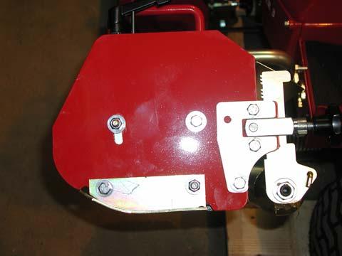
10 The seat is fitted with a safety cut-out switch which stops the engine as soon as the operator dismounts unless certain parameters are met. Should this happen, the ignition switch must also be turned off to prevent the battery discharging. Always wear stout shoes and suitable clothing. When operating the machine beware of children and animals; take care with bystanders, they may be deaf or blind. Before making any adjustments or clearing a blockage, STOP the engine and remove ignition key. When making adjustments to any part of the machine, particularly the cutting cylinders, take care not to trap fingers and do not attempt to free jammed or blocked cylinders by using the foot. Note: Whilst every precaution is taken in the selection of materials and components used in the manufacture of this machine. To ensure optimum performance and reliability, Allen Power Equipment Limited cannot accept liability for any damage to this machine or any possible lack of efficiency resulting from the improper use or incorrect maintenance of said machine. Allen Power Equipment Limited cannot accept any liability for damage to this machine or third party through operational negligence. Allen Power Equipment Limited reserve the right to alter specifications and prices as and when necessary ASSEMBLING THE MACHINE The machine comes partially assembled however the following operations are necessary prior to use. Fit the front cylinders noting that they are handed. These are fitted with the cylinder lift arms in the raised position. With the cylinders located on the arms install the cylinder retainer collar A with the lock pin B and secure with R clip, Fig. 1. The retainer collar is designed in such a way that it can only be fitted and removed with the cylinders in the raised position. Fit the front cylinder drive belts and adjust. (See section on adjustments). Lift the steering column and locate the steering console on the front two lugs pushing the console back. Lower the steering column so that it locates on the steering spigot C, Fig. 2. Use the special lock pin to connect the steering column to the steering gear Fig. 3. Fit the rear cover and screws E Fig. 4. Locate and secure the seat. Fill and charge the battery, fuel and oil the engine. Check engine manufactures information for the correct grade of oil to be used. Run the machine and check that all the necessary functions perform correctly. OPERATING THE MACHINE Read the Safety Instructions at the front of this manual. Ensure that the engine is in an operational condition, i.e. oil to level, petrol present, Drive Pedal F is in neutral, the Cylinder Drive (lever) G is disengaged and the Parking Brake H is engaged, Fig. 5 & 6. 9
11 WORKING INSTRUCTIONS SAFETY INTERLOCK SWITCHES The machine is fitted with a number of interlock switches to give additional safety to the customer. Here are some tips relating to the use of the switches:- Before the operator dismounts, the following must be effected: Engage the Parking Brake H, Fig. 6 Select neutral on Drive Pedal F, Fig. 6 Disengage Cylinder Drive (lever) G, Fig. 6 If all the above criteria are met the operator may dismount with the engine still running however if any of the above criteria are omitted the engine will stop. The engine will also stop if the operator tries to engage drive with the Parking Brake still engaged. TO START THE ENGINE Set the Throttle Control I. Fig. 6 to the choke position for cold start (midway through speed range for warm engine). Turn the key J, Fig. 6 clockwise until resistance is felt and then turn fully to operate the starter. When the engine starts, release the key. With the engine running cold, allow it to warm up and then move the Throttle Control I from the choke position to fast run. TO STOP THE ENGINE Operate the Throttle Control I to the slow run position and turn the Ignition Switch J, Fig. 6 anti-clockwise until the engine stops. STEERING The rear wheel steering is operated by a drag link from the steering wheel giving complete manoeuvrability. Become familiar with machine handling before attempting higher speeds or difficult manoeuvres. With the engine running at full speed, the machine may be used in either travelling or cutting mode. If travelling, ensure that all the cylinders are lifted and latched K, Fig. 1 and L, Fig. 5 into the travelling position and that the Cylinder Drive (lever) G, Fig. 6 is disengaged. Release the Parking Brake H, Fig. 6 and depress the Drive Pedal F, Fig. 6. The pedal is not an accelerator but controls the movement of the machine while not altering the engine speed. To move forward slowly, depress the front of the pedal. The further the pedal is pressed the faster the machine will go. To select neutral, simply bring the pedal to the central rest position to which it will automatically return. To select reverse slowly depress the rear of the pedal. CYLINDER DRIVE CLUTCH The Cylinder Drive (lever) G, Fig. 6 situated on the forward right hand side of the central seat mounting box, is the cutter drive clutch lever and this controls the drive to all cutter units. With the lever G in the lowered position Fig. 6, the drive is disconnected and it should always be in this position when stopping the machine. With the engine running, the Cylinder Drive may be engaged by lifting up the lever G slowly until it locks in position, Fig. 6 when all cylinders will then be revolving. Do not engage the Cylinder Drive when the mower units are in the transport position. SPEED CONTROL Forward or reverse speed control is achieved by operating the Drive Pedal F, Fig. 6 on the right hand footwell. The pedal operates a heavy-duty hydrostatic gearbox to give a smooth and progressive speed change. The further the pedal is depressed the faster the machine travels. Do not make rapid changes from forward to reverse as it could effect the machine s stability. Always disengage the Cylinder Drive (lever) G when in the transport position. Always lift all cylinders before travelling. 10
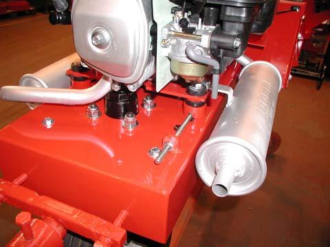
12 THROTTLE CONTROL The Throttle Control I, Fig 6 is a combined choke and engine speed control housed in one unit. The lever should be placed in the relevant position for the function required. BRAKE AND PARKING BRAKE When stopping the engine, raise the Parking Brake H, Fig. 5 and lock it on the lift latch plate. To release the Parking Brake H, Fig. 6 lift it over the latch and allow it to lower. The Parking Brake should always be engaged whenever the machine is stopped or left unattended. LIFTING & LOWERING MOWER UNITS Ensure that all the cylinders are disengaged, the Drive Pedal F is in neutral, the Parking Brake H is ON in the Engaged position and the engine is switched OFF at J. FRONT CYLINDERS To Lower Each front unit has two lift handles and a latch K, Fig. 1. To lower, lift the handle towards the centre of the machine, raise the latch K and lower the cylinder unit to the ground. Do not drop the unit as damage may occur. To Raise Reverse the above procedure. REAR CYLINDER To Lower Grasp the Rear Cylinder Lift Lever L, Fig. 5 located to the left of the central seat mounting box. Move the lever L forward to lower the cylinder unit. Do not drop the unit as damage may occur. To Raise Reverse the above procedure pulling back the lever L until it clicks into the raised position, Fig. 5. CUTTING WITH THE MACHINE The Trooper is designed to have all three cylinders operating at the same time. There is no method of disconnecting separate cylinders, therefore all cylinders must be lowered from the transport position on to the grass. With the engine running at half speed, engage Cylinder Drive (level) G, Fig. 6 by pulling the right-hand lever up and locking it in the raised position on the left latch plate. When all the cylinders are revolving, the Throttle I should then be set to full speed. Depress the Drive Pedal F to select the required forward speed. The length of grass will determine the height of cut and the forward speed. If the grass is long, 3 to 4 inches (76 to 102mm) then the cylinders will need to be set fairly high (adjustment is available from ½in to 2½in [12mm to 64mm]) and a low forward speed selected. If the grass is short then a lower height setting can be used and a faster forward speed may be selected. Full forward speed should only be used when the cutters are disengaged and are in the transport position and only when a clear straight run is available. The Throttle I should be set at maximum to allow the engine to run at its governed speed. Never allow the engine to labour, ease off the Drive Pedal F to slow the forward speed or alter the height of cut. MAINTENANCE Read the Safety Precautions. The following information is given to enable the owner/operator to obtain good service from the machine. Although maintenance has been reduced to a minimum, regular attention to lubrication, adjustments and cleanliness is important. Left or right hand is determined from the operating position sitting on the machine. MAINTENANCE PRECAUTIONS When refuelling, stop the engine, do not smoke and use a funnel when pouring fuel from a can to ensure that none is spilt onto hot parts of the engine, i.e. exhaust silencer, cylinder, etc. 11
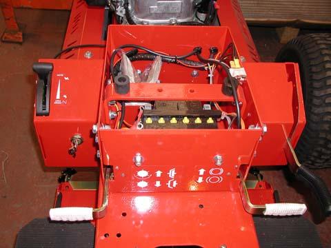
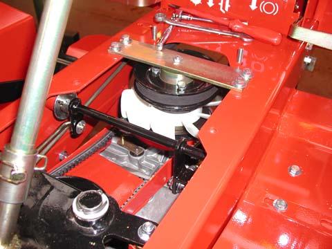
13 If working on lifted parts ensure that adequate support is provided. Do not alter engine speed above the maximum quoted in the engine specification. Before making any adjustment or clearing a blockage, STOP the engine. When making adjustments to any part of the machine, particularly the cutting cylinders, take care not to trap fingers and do not attempt to free jammed or blocked cylinders by using the foot. LUBRICATION In normal ambient conditions (above 4º Centigrade or 40º Fahrenheit) an SAE 30 oil is recommended for the cutter T drive gearbox and the hydrostatic transaxle. For temperatures below this consult your supplying dealer. ENGINE LUBRICATION The machine is fitted with a four stroke engine, this being lubricated by oil in the crankcase. The engine is filled with oil at manufacture. However, care must be taken to ensure that the oil is to the engine manufacturer s required level (see engine manual) prior to and during use. Take care not to overfill the crankcase. Use only oils to engine manufacturer s specifications. Adhere carefully to the engine manufacturer s operating and maintenance instructions, particularly with regard to air cleaner servicing. MACHINE LUBRICATION The transaxle and bevel gearboxes are filled with lubricant on assembly and no further attention should be required. The cylinder bearings are sealed for life and so do not require lubrication. Grease should be applied, every 25 working hours, to the greasers fitted to all the mower pivot points, Fig. 12 and to all the roller greasers. Use Castrol L.M. grease or equivalent. Occasionally lubricate all other moving parts by oil can, in particular the Throttle Control at the lever and engine ends, cylinder unit latches, neutral adjustment plungers, exposed screw threads on mower adjustments etc. BATTERY On receiving the new machine fill the battery with concentrated acid and fully charge prior to initial use. This ensures battery longevity and should be carried out by the supplying dealer. Check that the vent-tube N, Fig. 11 is fitted and is clear. The output should pass through the hole in the chassis below the battery. BATTERY ACID IS HIGHLY CORROSIVE AND EXTREME CARE SHOULD BE TAKEN TYRES Keep all tyre pressures at 15Ib/in 2 (1.0 bar). ADJUSTMENTS Read the Safety Precautions. STEERING LINKAGE The drag link can be adjusted quite simply by removing the clip from the rear of the link rod and adjusting the length prior to re-insertion. DRIVE TRAIN ADJUSTMENTS Most adjustments that may be required from time to time are carried out by first removing the main access panel on the top of the machine. To effect this, undo the eight Access Panel Screws E, Fig. 4 and remove the panel. By withdrawing the Steering Column Pin C, Fig. 2 & 15, the steering column can then be disengaged allowing the removal of the entire steering housing. This gives free access to the majority of the working parts and makes for ease of service. MAIN DRIVE BELT The Main Drive Belt O, Fig. 14 and 15, is tensioned by slackening the four engine mount bolts and tensioning the adjuster screw. M fig 10. Retighten securely. 12
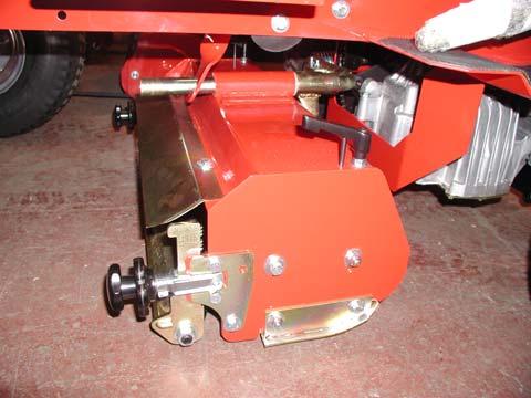
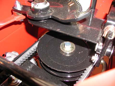
14 If belt replacement is necessary, remove the main access panel as detailed above R. Then remove the Locating Spigot Bar from the fan/pulley assembly, Fig. 15 and separate the fan/pulley assembly, Fig. 15 and the coupling, Fig. 2. The Belt O can be replaced easily. Lay the belt into its pulley and the engine pulley. Refit the Fan/Pulley assembly and Locating Spigot Bar allowing the rubber coupling to align with the coupler halves. Once the four Spigot Bar retaining bolts have been replaced and tightened, the belt O can be tensioned as described above. Correct tension is when the belt can be deflected 12mm at its mid point with finger pressure. Take extreme care not to trap fingers or clothing. DO NOT USE THE ELECTRIC STARTER Check that the belt is installed correctly and that it is not rubbing anywhere. CYLINDER DRIVE BELT ADJUSTMENT Screw the Cylinder Drive Belt Adjuster P Fig. 16 away from the body of the machine to increase tension on the cylinder drive belt and towards the machine to slacken the belt tension. The tension should be set to a deflection of 20mm as shown in Fig. 15. CYLINDER CLUTCH DRIVE BELT Having removed the main access panel, remove the Main Drive Belt O, Figs. 14 and 15, by loosening and removing the Locating spigot Bar, R Fig. 2 and separating the coupling Fig. 2. Then undo the screw, Fig. 17, which secures the top of the cutter T drive pulley and raise the pulley. The belt Q, Figs. 15 and 17, can now be removed freely and replaced. To replace, reverse the above procedure. Slackening the engine mount bolts, allows the engine to move forward CYLINDER CLUTCH ADJUSTMENT The clutch is designed to be partially selfadjusting, however periodic inspection should be carried out to ensure that optimum performance is being attained. It is not necessary to remove the clutch rod, disconnect the clevis pin from the clevis. Adjust on the thread to suit. Reassemble. Note: - It is not necessary to overtighten on clutching. Should adjustment be necessary, tighten or loosen the clutch rod by removing it and adjusting its length, Fig. 18. HEIGHT OF CUT The cutting height of each cylinder unit is determined by the position of the rear rollers. Adjustments can be varied from ½in to 2½in (12mm to 64mm). To Adjust 1. Park the machine on flat, level ground. Stop the engine, engage the Parking Brake H and disengage the Cylinder Drive (Lever) G. 2. Slacken the Knurled knob R fig 12 and reposition the roller end plates using the teeth. These are arranged in sets of 3 for ease of identification. 3. A practical tip when positioning the roller. Remember the blade cutting edge is ½in (12mm) up from the underside of the bottom blade. CUTTING CYLINDER TO BOTTOM BLADE Please note that cylinders are sharp and care must be taken at all times. To check that a cutting cylinder is set correctly in relation to the bottom blade, proceed as follows: - Stop the engine, slacken the Cylinder Drive Belt Adjusters P, Fig. 16, hold a thin piece of paper between the edge of the bottom blade and a spiral cutter and rotate the cylinder manually. If correctly set, the paper should cut cleanly along the length of the bottom blade. If it does not then adjustment may be 13
15 necessary. Removal of the Cylinder Belt greatly eases this operation. Note: The performance of a blunt cylinder/bottom blade will not be improved by tightening the cylinder to the bottom blade. In such cases the cylinder/bottom blade needs to be sharpened. TO ADJUST The cylinder is supported by two swivel bearing housings. See Fig.13. Raise the adjustment levers T from their locked position, rotate about 180 and lower the lever. Turning ANTI CLOCKWISE moves the cylinder down to the bottom blade. Once the blades are cutting evenly return the adjuster to its locked (locked position) Always complete the adjustment by moving the cylinder DOWN. This ensures that any free play in the mounting is taken out Always be extremely careful when rotating the cylinder by hand. Always use paper long enough to keep fingers away from the cutting edge. Never attempt to touch or check cylinders when they are moving under power or even when the engine is running. Remember: Unless belts are removed, turning ONE cylinder TURNS ALL THREE. GUARANTEE If there is any component, or components, manufactured by ALLEN POWER EQUIPMENT LTD that is found to be defective within 12 months from the date of purchase (or in the case of a machine used for hire purposes, 45 days). ALLEN POWER EQUIPMENT LTD undertake to replace the faulty component/components free of charge through authorised dealers. The following are NOT covered under this Guarantee: 1. A NEW MACHINE which has been subject to operation in excess of recommended capacities, misuse, negligence or accident, or has been altered or modified in a manner not authorised by ALLEN POWER EQUIPMENT LTD. 2. TRANSPORTATION charges to and from an authorised dealer. ALLEN POWER EQUIPMENT LTD operate a policy of continual improvement and reserve the right to alter product specification without giving prior notice. After each season, we recommend that you have your machine serviced by your dealer, preferably between October and January, to avoid delay at the start of the following season. REAR CYLINDER PITCH To ensure that the rear cylinder cuts the same height as the front two adjust the pitch using the M8 clamp bolts Fig. 20. This may be necessary after striking foreign objects. PARKING BRAKE The internal disc brake fitted to the transaxle is operated by the Parking Brake Lever G, Fig. 5 and is self-adjusting, no further maintenance is necessary. 14
16 SPARE PARTS LIST 15
17 MAIN FRAME ASSEMBLY 16
18 MAIN FRAME ASSEMBLY ITEM No. Part No. DESCRIPTION QTY MAIN BODY FRONT COVER PLATE NEUTRAL LEVER SEAT BOX LID RUBBER BUSH FRONT PULLEY SCRAPER FOOTPLATE FOOTPLATE MATTING SEAT BOX ASSEMBLY BODY FRONT STRAP POD SWITCH SIDE POD LIFT SIDE POD COVER TOOL TRAY HEX HD SETSCREW, M8 X WASHER, M NYLOC NUT, M SEAT ASSEMBLY SHIELD SUPPORT SHIELD SPACER SILENCER SHIELD REEL CATCH ROLL PIN RUBBER STOP 2 17
19 DRIVE ASSEMBLY 18
20 DRIVE ASSEMBLY ITEM No. PART No. DESCRIPTION QTY ENGINE (NOT SHOWN) EXHAUST BASEPLATE ISOLATOR SPACER TENSION ADJUSTER HUB DRIVE PULLEY MAIN DRIVE BELT DRIVE COUPLING ASSEMBLY MOUNTING PLATE PULLEY SHAFT HUB BEARING UPPER COUPLING RUBBER COUPLING LOWER COUPLING FAN ADAPTOR TRANSAXLE PULLEY SPACER DISC GEARBOX PULLEY V BELT BELT GUIDE SHAFT GEARBOX & PULLEY ASSEMBLY TRANSAXLE & WHEEL HUBS MOUNTING BRACKET AIR BREATHER ASSEMBLY FELT PLUG ADAPTOR MINATURE SILENCER O RING WHEEL & TYRE ASSEMBLY (NOT SHOWN) MICROSWITCH MOUNTING PLATE ACTUATOR THROTTLE CABLE (NOT SHOWN) 1 19
21 DRIVE ASSEMBLY 20
22 DRIVE ASSEMBLY ITEM No. PART No. DESCRIPTION QTY HEX HD BOLT, M WASHER, M NUT PLAIN, M HEX HD SETSCREW, M WASHER, M8 SPECIAL BEARING 1 46 PARALLEL KEY, M BEARING & HOUSING 2 48 BOLT CAP HEAD, M WASHER SPRING, M6 3 21
23 STEERING ASSEMBLY 22 &
24 STEERING ASSEMBLY ITEM No. PART No. DESCRIPTION QTY STEERING COWLING STEERING WHEEL COVER PLATE WASHER, M NYLOC NUT, M LOWER COWLING HEX HD SETSCREW, M WASHER, M SHAFT ROLL PIN BUSH WASHER, STARLOCK SPUR GEAR SHAFT LOCKING PIN BEARING SPACER BEARING HOUSING WASHER, M NYLOC NUT, M MOUNTING PLATE SPACER QUADRANT NYLON WASHER SPLIT PIN CONNECTOR 1 26 BUSH STEERING LINK ARM CLEVIS, LONG SPRING PIN PLATE HEX HD BOLT, M WASHER, M NYLOC NUT, M REAR HUB/AXLE TYRE & WHEEL ASSEMBLY RUBBER BUSH BUSH 2 38 BEARING (SUPPLIED WITH ITEM 35) NUT NYLOC, M
25 CUTTING CYLINDER ASSEMBLIES
26 CUTTING CYLINDER ASSEMBLIES ITEM No. PART No. DESCRIPTION QTY REEL ASSEMBLY (LH) REEL ASSEMBLY (RH) REEL ASSEMBLY (REAR) BODY (LH) 1 BODY (RH) 1 BODY (REAR) GREASE NIPPLE A/R PULLEY ROLL PIN GUARD (LH) GUARD (RH) GUARD (REAR) SPACER SPACER SCRAPER SPACER HEX HD BOLT, M8 X WASHER, M8 A/R NYLOC NUT, M8 A/R DEFLECTOR HEX HD SETSCREW, M8 X NUT, M8 A/R MOWER REEL (LH) MOWER REEL (RH & REAR) RATCHET HANDLE ADJUSTER ROD ADJUSTER NUT BEARING HOUSING BEARING TOLERANCE RING SKID FOOT HEX HD BOLT, M8 X LOCATION BUSH BOTTOM BLADE SUPPORT BLADE CSK HD SCREW REAR ROLLER BEARING CIRCLIP INTERNAL ADAPTOR LOCK NUT, M SPRING WASHER, M SCRAPER BAR 2 25
27 CUTTING CYLINDER ASSEMBLIES
28 CUTTING CYLINDER ASSEMBLIES ITEM No. PART No. DESCRIPTION QTY KNOB CLEVIS SPRING PIN ROLLER CARRIER PLATE FIXED PLATE (INNER) FIXED PLATE (OUTER) SOCKET SCREW, M SUPPORT ARM TORSION SPRING (LH & REAR) TORSION SPRING (RH) PUSH PLATE END TUBE (LH) END TUBE (RH) PIN A/R R CLIP A/R SUPPORT ARM REAR SUPPORT ARM REAR FRONT SUPPORT TUBE WASHER, BELT ( LH & RH) BELT (REAR) 1 27
29 LINKAGE ASSEMBLIES 28
30 LINKAGE ASSEMBLIES ITEM No. PART No. DESCRIPTION QTY FOOT PEDAL GLACIER BUSH ROLL PIN PEDAL ROD BUSH LARGE WASHER PEDAL RETURN LINK PLATE PLUNGER SPRING NYLOC NUT, M DAMPER BRACKET 1 14 DAMPER MOUNTING PLATE DIRECTION ROD CLEVIS CLEVIS SPRING PIN CLUTCH CONTROL ARM GRIP CLUTCH ACTUATION ROD TRANSFER PLATE TRANSFER ROD R CLIP LIFT HANDLE GRIP LIFT BAR SPRING WASHER NYLOC NUT, M HEX HD BOLT, M LIFT LINK LIFT BUSH 1 33 CLAMP BRAKE CONTROL ARM BRAKE LEVER ARM 1 36 SPRING 1 37 SPLIT PIN M GRUB SCREW M5 1 29
31 ELECTRICAL ASSEMBLY 30
32 ELECTRICAL ASSEMBLY ITEM No. PART No. DESCRIPTION QTY BATTERY BATTERY STRAP WASHER FLAT, M NYLOC NUT, M8 2 5 VENT TUBE (SUPPLIED WITH ITEM 1) 1 6 BATTERY LEAD Battery to starter BATTERY LEAD Battery to earth LEAD Battery to engine alternator IGNITION SWITCH & KEYS MICRO SWITCH 5 11 WIRING HARNESS IN-LINE FUSE HOLDER - + Battery terminal AMP FUSE HEX HD BOLT, M8 X
33 WIRING DIAGRAM 32
34 autoguide equipment Heddington, Nr Calne, Wiltshire, SN11 0PS Telephone: +44 (0) Fax: +44 (0)
Kubota Rear Discharge Mowers 1.3m
 Operating instructions and parts manual for Kubota Rear Discharge Mowers 1.3m (For G2160 Tractors) autoguide equipment Heddington, Nr Calne, Wiltshire, SN11 0PS Telephone: +44 (0) 1380 850885 Fax: +44
WESTWOOD GARDEN TRACTORS 1983 PARTS CATALOGUE CONTENTS
 WESTWOOD GARDEN TRACTORS 1983 PARTS CATALOGUE CONTENTS PAGE No. W6R, W6E, W8E/28, W8C UPPER FRAME, BONNET & GRILLE, CONSOLE, ELECTRICAL, SEAT, STEERING WHEEL, ROAD WHEELS 2 3 W8E, W11C, W11E UPPER FRAME,
Wheel Horse. 42 Mower. for Lawn and Garden Tractors. Model No & Up. Operator s Manual
 FORM NO. 9 559 Rev A Wheel Horse 4 Mower for Lawn and Garden Tractors Model No. 78 890000 & Up Operator s Manual IMPORTANT: Read this manual carefully. It contains information about your safety and the
STIGA TORNADO 51 S 51 SE PRO 51 S
 STIGA TORNADO 51 S 51 SE PRO 51 S 8211-0225-09 SVENSKA S 1 2 3 1. 2. ADD FULL FULL ADD ADD FULL 0,15 l. 3. LS 45 4. XTE 60 3x 5. LS 45 6. XTE 60 STOP I H 7. 8. 2 S SVENSKA 9. 10. 11. 12. LS 45 0,75 mm
Agri-Fab OWNERS MANUAL. Model No " ROUGH CUT TRAILMOWER. CAUTION: Read Rules for Safe Operation and Instructions Carefully
 Agri-Fab OWNERS MANUAL Model No. 45-0362 CAUTION: Read Rules for Safe Operation and Instructions Carefully Safety Assembly Operation Maintenance Parts 42" ROUGH CUT TRAILMOWER NOTE: Your mower deck will
GUARANTEE. Purchased from. Manufactured by:
 GUARANTEE If there is any component, or components, manufactured by ALLEN POWER EQUIPMENT LTD that are found to be defective within 12 months from the date of purchase (or in the case of a machine used
HYDRO RIDER. DRWG No: R ISSUE No: Alternative Belt Retaining Bracket
 91 90 9 97 9 9 HYDRO RIDER 7 1 79 0 9 1 7 77 DRWG No: R0001 ISSUE No: 1 0 0 9 0 7 9 9 9 99 7 7 11 1 0 9 9 1 7 Alternative Belt Retaining Bracket 9 1 1 0 1 1 1 1 71 70 7 1 1 9 7 7 1 1 7 0 0 7 9 7 1 9 1
Operating Instructions
 Please Read These Instructions Before Using Your Mower Operating Instructions for model HP470 & SP470 Lawnmowers with Briggs & Stratton engine Product Codes: 99646/BQ 97646/BQ Call our Helpline if you
SERIES GARDEN TRACTORS 1992 PARTS CATALOGUE CONTENTS
 2000 SERIES GARDEN TRACTORS 1992 PARTS CATALOGUE CONTENTS PAGE No. 2000 SERIES GARDEN TRACTOR - CHASSIS, BODY PANELS, WHEELS, SEAT ETC 2 4 2000 SERIES PTO DRIVE, FRONT AXLE, ELECTRICS, MOUNTING FRAME AND
TO THE OWNER ASSEMBLY
 TO THE OWNER This is an operational and general maintenance manual only and does not cover repair. All repair work must be performed by an authorized BOLENS DEALER or the factory warranty is void. Bolens
48 Side Discharge Mower
 FORM NO. 9 650 Rev A Wheel Horse 8 Side Discharge Mower for Classic Garden Tractor Model No. 786 890000 & Up Operator s Manual IMPORTANT: Read this manual carefully. It contains information about your
Wheel Horse. 52 Mowers. Model No & Up Model No & Up. Operator s Manual
 FORM NO. 9-567 Wheel Horse 5 Mowers for Lawn & Garden Tractors Model No. 7880 890000 & Up Model No. 7885 890000 & Up Operator s Manual IMPORTANT: Read this manual carefully. It contains information about
Wheel Horse. 44 Snowthrower. for 5xi Lawn and Garden Tractors. Model No & Up. Operator s Manual
 FORM NO. 8 Rev A Wheel Horse Snowthrower for 5xi Lawn and Garden Tractors Model No. 7966 890050 & Up Operator s Manual IMPORTANT: Read this manual, and your tractor manual, carefully. They contain information
DEUTSCHER HE660 OWNER S INSTRUCTION MANUAL AND PARTS LIST
 www.deutschermowers.com.au DEUTSCHER HE660 OWNER S INSTRUCTION MANUAL AND PARTS LIST INDEX 3-4... Assembly Instructions 5-6... Safety Instructions 7... Routine Care and Storage 7... Specifications 8-9...
M. E. Y. EQUIPMENT MOWER MANUAL
 M. E. Y. EQUIPMENT MOWER MANUAL 200 COLLIER ROAD, BAYSWATER. WESTERN AUSTRALIA 6053 TELEPHONE (08) 9370 1110, FACSIMILE (08) 9370 2566 Web Site: www.mey.com.au Email: info@mey.com.au INTRODUCTION The technical
Owners Manual MODEL 45 REEL MOWER MODELS & 45148
 Owners Manual MODEL 45 REEL MOWER TM MODELS 45048 & 45148 TM Rover Mowers Limited Model 45 FOREWORD Thank you for buying a Rover Mower. This manual covers the operation and maintenance of the Rover Model
KING COBRA/CALIBER GRASS COLLECTION SYSTEM PARTS & OPERATORS MANUAL
 KING COBRA/CALIBER GRASS COLLECTION SYSTEM PARTS & OPERATORS MANUAL GRASS CATCHER W/WEIGHTS: TUBE KITS: BLOWER KITS: 52 542128 52 542119 5101002 60 542129 60 542120 5101003 2 WORLDLAWN POWER EQUIPMENT
Worldlawn Power Equipment, Inc. Industrial Park 2415 Ashland Ave. Beatrice, NE Toll Free Number:
 Operator s Manual R WYZ48/52/60CS BAGGER Worldlawn Power Equipment, Inc. Industrial Park 2415 Ashland Ave. Beatrice, NE 68310 Toll Free Number: 1-800-267-4255 OPERATOR S MANUAL This catcher manual is for
Wheel Horse. 48 Mower. for Lawn and Garden Tractors. Model No & Up. Operator s Manual
 FORM NO. 5 Wheel Horse 48 Mower for Lawn and Garden Tractors Model No. 786 990000 & Up Operator s Manual IMPORTANT: Read this manual carefully. It contains information about your safety and the safety
FIELD KIT FITTING INSTRUCTIONS FOR TR3
 24795G-GB (rev.1) FIELD KIT FOR TR3 Rear Roller Brush Kit LMAC185-TR3-F for "Fairway" style Cutting Units Series: AAG, AAH, AAJ, AAK IMPORTANT NOTE - TR3 ONLY Grassboxes cannot be used with these Cutting
WESTWOOD GARDEN TRACTORS PARTS CATALOGUE CONTENTS
 WESTWOOD GARDEN TRACTORS 1984-1986 PARTS CATALOGUE CONTENTS PAGE No. S600R, S600E, S800E AND S1000 UPPER FRAME, BONNET & GRILLE, CONSOLE, ELECTRICAL, SEAT, STEERING WHEEL, ROAD WHEELS 2 3 T800 AND T1100
Parts Manual PZ Please read the operator manual carefully and make sure you understand the instructions before using the machine.
 Parts Manual PZ 60 967 045601-00 Please read the operator manual carefully and make sure you understand the instructions before using the machine. When you need spare parts or support in service questions,
Operating Instructions
 Please Read These Instructions Before Using Your Mower Operating Instructions for SP470 ES Lawnmower with Briggs & Stratton engine Product Code: 99468/BQ Call our Helpline if you have any problems: Helpline
WYZ34FS600VCA FOR SERIAL NUMBERS U02011 AND ABOVE
 PARTS MANUAL WYZ34FS600V WYZ34FS600VCA FOR SERIAL NUMBERS 201610U02011 AND ABOVE 2 3 4 CONTENTS GENERAL INFORMATION... 6 SERVICE LOCATOR CHART... 7 DECK ASSEMBLY... 8 DECK LIFT ASSEMBLY... 10 FRAME ASSEMBLY...
Agri-Fab OWNERS MANUAL. Model No " ROUGH CUT TRAILMOWER. CAUTION: Read Rules for Safe Operation and Instructions Carefully
 Agri-Fab OWNERS MANUAL Model No. 45-03071 45-0361 CAUTION: Read Rules for Safe Operation and Instructions Carefully Safety Assembly Operation Maintenance Parts 42" ROUGH CUT TRAILMOWER the fastest way
Part s Catalog. GT2100 Garden Tractor. Model No. 14AP80RP744. Original Instructions (EN) (01/31/06)
 (01/31/06)") Part s Catalog GT0 Garden Tractor Model No. AP0RP Original Instructions (EN) -0 (0//0) Model P0RP -0-00 Turf Tire, x. x -0-00 Rim,.0 x.0-00 Lug Nut, /- -00A-0 Wheel Assembly, x. x -00-00 Rim Assembly,.0
Part s Catalog GT0 Garden Tractor Model No. AP0RP Original Instructions (EN) -0 (0//0) Model P0RP -0-00 Turf Tire, x. x -0-00 Rim,.0 x.0-00 Lug Nut, /- -00A-0 Wheel Assembly, x. x -00-00 Rim Assembly,.0
Part s Catalog. LX500 Lawn Tractor. Model No. 13AP60RP744. Original Instructions (EN) (01/31/06)
 (01/31/06)") Part s Catalog For Parts Call 0-- or 0-- LX00 Lawn Tractor Model No. AP0RP Original Instructions (EN) -0 (0//0) For Parts Call 0-- or 0-- Model P0RP NUMBER --00 Turf Tire, 0 x 0.0 x -000-00 Rim,.0 x.0-0-0
Part s Catalog For Parts Call 0-- or 0-- LX00 Lawn Tractor Model No. AP0RP Original Instructions (EN) -0 (0//0) For Parts Call 0-- or 0-- Model P0RP NUMBER --00 Turf Tire, 0 x 0.0 x -000-00 Rim,.0 x.0-0-0
36 Rear Discharge Mower
 FORM NO. 8 95 Rev. A Wheel Horse 6 Rear Discharge Mower for Classic Garden Tractor Model No. 7805 790000 & Up Operator s Manual IMPORTANT: Read this manual carefully. It contains information about your
Finishing Mower Estate 72
 Finishing Mower Estate 72 Owners/Operators Manual & Spare Parts List Issue Date: October 2011 1 Introduction Your FIELDMASTER Estate 72 Finishing Mower has been designed to do a range of work to your satisfaction.
Hydrostatic Zero-Turn Commercial Riding Mower
 Hydrostatic Zero-Turn Commercial Riding Mower Professional Turf Equipment 0" Fabricated Deck ILLUSTRATED PARTS LIST TABLE OF CONTENTS Frame Assembly.................................. 3 0" Fabricated Cutter
GRASS CATCHER PART S & OPERATORS MANUAL
 GRASS CATCHER PART S & OPERATORS MANUAL WORLDLAWN POWER EQUIPMENT, INC. WORLDLAWN.COM 2415 ASHLAND AVE BEATRICE, NE 68310 800-267-4255 FAX 402-223-4103 2 3 4 OPERATORS MANUAL This catcher manual is for
Model S-777NA USER MANUAL. Please ensure this manual is read and understood before using the scooter.
 Model S-777NA USER MANUAL Please ensure this manual is read and understood before using the scooter. CONTENTS Introduction 3 Feature Guide 3 Safety Advice 4 Adjustments 5 Tiller Angle Adjustment Seat Swivel
GROUNDSMASTER. 52 Recycler. for 120 Traction Unit. Model No & UP. Operator s Manual
 FORM NO. 8-980 Rev A GROUNDSMASTER 5 Recycler for 0 Traction Unit Model No. 077 79000 & UP Operator s Manual IMPORTANT: Read this manual carefully. It contains information about your safety and the safety
DIAMONDBACK/EDGE GRASS COLLECTION SYSTEM PARTS & OPERATORS MANUAL
 DIAMONDBACK/EDGE GRASS COLLECTION SYSTEM PARTS & OPERATORS MANUAL GRASS CATCHER W/WEIGHT: TUBE KIT: BLOWER KIT: 48 5101305 632093 632078 52 5101305 542119 632074 60 632086 542120 632081 3 WORLDLAWN POWER
Kubota Mulching Mower 1.5m (F60 Series)
") Operating instructions and parts manual for Kubota Mulching Mower 1.5m (F60 Series) autoguide equipment Stockley Road, Heddington, Nr Calne, Wiltshire, SN11 0PS England Telephone: +44 (0) 1380 850885 Fax:
Operating instructions and parts manual for Kubota Mulching Mower 1.5m (F60 Series) autoguide equipment Stockley Road, Heddington, Nr Calne, Wiltshire, SN11 0PS England Telephone: +44 (0) 1380 850885 Fax:
Parts Manual Rev. A RZT48 /
 115 91 36-2 Rev. A Parts Manual RZT48 / 96 62001-00 Please read the operator manual carefully and make sure you understand the instructions before using the machine. Gasoline containing a maximum of 10%
Operator s Manual. GreenTek Ltd Rudgate Walton Leeds LS23 7AU UK
 Double Quick Operator s Manual GreenTek Ltd Rudgate Walton Leeds LS23 7AU UK Certificate of CE Conformity Date: 10 February 2003 Machine Model: Description: Double-Quick Interchangeable Turf Maintenance
REAR ENGINE RIDER 42 MOWER SERIES 22
 Parts Manual for REAR ENGINE RIDER MOWER SERIES MODELS 1BVE CONTENTS DESCRIPTION PAGE(S) DESCRIPTION PAGE(S) WHEELS- TIRES... - FRONT END, STEERING.... - MAIN CASE... - DIFFERENTIAL, R. H. FENDER... 8-9
PARTS MANUAL SECTION 111
 P - SERIES ZERO TURN MOWER MODELS P5525CT, P6124FS, P6126KP, P6127CT Published 11/15 S MANUAL SECTION 111 An Operator's Manual was shipped with the equipment. The Operator's Manual is an integral part
Parts Manual Rev. B RZT48 /
 115 91 36-2 Rev. B Parts Manual RZT48 / 96 62001-00 Please read the operator manual carefully and make sure you understand the instructions before using the machine. Gasoline containing a maximum of 10%
Hydrostatic Zero-Turn Commercial Riding Mower
 Hydrostatic Zero-Turn Commercial Riding Mower Professional Turf Equipment 54" Fabricated Deck ILLUSTRATED PARTS LIST TABLE OF CONTENTS Frame Assembly.................................. 3 54" Fabricated
DENNIS G680 MOWER INSTRUCTION MANUAL
 DENNIS G680 MOWER INSTRUCTION MANUAL Publication No. G680ins(Wargraves 3 Roller section).doc DENNIS, Ashbourne Road, Kirk Langley, Derby, DE6 4NJ Telephone: 01332 824777 Fax: 01332 824525 e-mail sales@dennisuk.com
TimeCutter ZS 5000 Riding Mower
 Form No. 3409-408 Rev A TimeCutter ZS 5000 Riding Mower Model No. 74661 Serial No. 400000000 and Up Register at www.toro.com. Original Instructions (EN) *3409-408* A Ordering Replacement Parts To order
Parts Manual SERIES CVT Lawn Tractor. Model LT1040 CUB CADET LLC, P.O. BOX CLEVELAND, OHIO PRINTED IN U.S.A.
 Parts Manual CVT Lawn Tractor SERIES 000 Model LT00 PRINTED IN U.S.A. CUB CADET LLC, P.O. BOX CLEVELAND, OHIO -00 FORM -00C.fm (//00) SERIES 000 CVT LAWN TRACTORS TABLE OF CONTENTS DESCRIPTION PAGE Axle,
AUTO-ROTORAKE Mk.5 INSTRUCTION MANUAL
 R AUTO-ROTORAKE Mk.5 INSTRUCTION MANUAL SP20008_REV_1 10/12 Certificate of Conformity Auto-Rotorake CN Code: 8432 29 10 Manufacturer:- Howardson Ltd, Howardson Works, Kirk Langley, Derby, DE6 4NJ. UK Owner
48 Side Discharge Mower
 FORM NO. 9 7GB Wheel Horse 48 Side Discharge Mower for Lawn & Garden Tractors Model No. 7868 790000 & Up Operator s Manual IMPORTANT: Read this manual carefully. It contains information about your safety
TWIN DRIVE REEL MOWER
 Issue A May 1 IPL Part # 7 TWIN DRIVE REEL MOWER Part Number 0 From Serial Number 5 Issue A May 1 IPL Part # 7 ROLLER ASSEMBLY, 00, 0, 0 Powered by: HP Tecumseh 5 Golf, 0C, 0S 5 5 0 7 5 5 175 5 1 1 1 0
Series 1000 and Cutout
 17.15.Remove the belt from the tractor. NOTE: There were a small number of tractors made using a CVT drive and a 2-speed (L-H-N-R) GT transaxle. The belt must pass over the center mounted gear selector
Z Master. 62 Mower. for Z Master Z 255 Traction Unit. Model No & UP. Operator s Manual
 FORM NO. 9 88 Z Master 6 Mower for Z Master Z 55 Traction Unit Model No. 7408 89000 & UP Operator s Manual IMPORTANT: Read this manual carefully. It contains information about your safety and the safety
HAMMER KNIFE FLAIL MOWER SHREDDER
 HAMMER KNIFE FLAIL MOWER SHREDDER Operation, Service, & Parts Manual For Models: GOL79 & GOL89 October 2010 FORM: GOLShredder.QXD TABLE OF CONTENTS Installation....................................................1
Parts Manual Zero Turn Mower / Z 248F
 Parts Manual Zero Turn Mower / Z 248F 967262501-00 Please read the operator manual carefully and make sure you understand the instructions before using the machine. When you need spare parts or support
Kubota Mulching Mowers 1.3m
 Operating instructions and parts manual for Kubota Mulching Mowers 1.3m (For G2160 Tractors) autoguide equipment Heddington, Nr Calne, Wiltshire, SN11 0PS Telephone: +44 (0) 1380 850885 Fax: +44 (0) 1380
AUTO-ROTORAKE Mk.5 INSTRUCTION MANUAL
 AUTO-ROTORAKE Mk. INSTRUCTION MANUAL SP20008_REV MAY 2018 CERTIFICATE OF CONFORMITY Auto-Rotorake CN Code: 842 29 10 Manufacturer:- Howardson Ltd, Howardson Works, Kirk Langley, Derby, DE6 4NJ. UK Owner
STIGA DINO 45 EURO TORNADO
 STIGA DINO 45 EURO TORNADO 45 8211-3389-08 SVENSKA S 1. 2. 1 2 3 4 3. 4. FULL ADD ADD FULL 5. 6. STOP G G 7. 8. EURO 2 S SVENSKA 3 2 1 3x 9. 10. 0,76 mm 0,75 mm 11. 12. 40 Nm 13. 3 SVENSKA S 4 GB ENGLISH
CALIFORNIA TRIMMER MOWER MAINTENANCE MANUAL
 CALIFORNIA TRIMMER MOWER MAINTENANCE MANUAL 2 Table of Contents Section 1: General Information Page Handle Assembly Instructions 4 Maintenance All Models 6 Oil Change Procedures All Models 9 Height Adjustment
365L (2001) Page 1 of 36 54" Deck Assembly
 Page 1 of 36 54 Deck Assembly") 365L (2001) Page 1 of 36 54" Deck Assembly 365L (2001) Page 2 of 36 54" Deck Assembly 1 720-0241 1 S Wing Nut Knob 2 703-2817 1 Belt Cover LH 3 703-2816 1 Belt Cover RH 4 747-3306 1 Idler Spring Mounting
365L (2001) Page 1 of 36 54" Deck Assembly 365L (2001) Page 2 of 36 54" Deck Assembly 1 720-0241 1 S Wing Nut Knob 2 703-2817 1 Belt Cover LH 3 703-2816 1 Belt Cover RH 4 747-3306 1 Idler Spring Mounting
Pacer Series Transaxle Drive Walk-Behind Mower
 Parts Manual Pacer Series Transaxle Drive Walk-Behind Mower 15HP Product Mfg. No. Description 1694895 Pacer, 15HP B&S Walk-Behind 2690447 Pacer, 15HP B&S w/34" Deck 17HP Product Mfg. No. Description 5900630
Brake Upgrade Kit Fitting Instructions Bonneville America
 WARNING: Always have Triumph approved parts, accessories and conversions fitted by a trained technician of an authorised Triumph Dealer. The fitment of parts, accessories and conversions by a technician
Parts Manual Rev. A RZT54 /
 115 93 37-27 Rev. A Parts Manual RZT54 / 967 672101-00 Please read the operator manual carefully and make sure you understand the instructions before using the machine. Gasoline containing a maximum of
Berta Flail Mower Attachment. BCS Power Units
 Manufactured by Berta s.r.l. to fit BCS Power Units Operating Instructions Before commissioning the machine, read operating instructions and observe warning and safety instructions. PLEASE ALSO READ ORIGINAL
Hydro Cut Series Walk-Behind Mowers
 Parts Manual HP Product Mfg. No. Description 92 Hydro Cut, HP Kawasaki, 2 inch (CE) Hydro Cut Series Walk-Behind Mowers Rev. 0/200 Table Of Contents PRODUCT COMPONENTS PAGES Engine Deck & Handle Bars
PORTABLE CONCRETE VIBRATOR
 PORTABLE CONCRETE VIBRATOR OPERATION MANUAL MODEL PV45S INTRODUCTION We have taken care in the selection, testing and design of this product. Should service or spare parts be required this can be provided
TR3 Series: EJ - 26" Cutting Units - Engine type: Kubota D1105-E - Product code: TR30001
 24745G-GB (rev.0) Fitting Instructions For Backlap Kit LMAC161 TR3 Series: EJ - 26" Cutting Units - Engine type: Kubota D1105-E - Product code: TR30001 WARNING: If incorrectly used this machine can cause
TECHNICAL DATA BROCHURE ZTR 308/3II
 Date 8/84 Page 1 of 6 TECHNICAL DATA BROCHURE ZTR 308/3II IMPORTANT - READ OPERATOR'S MANUAL BEFORE OPERATION OR MAKING ADJUSTMENTS. ' Seat Adjustment Loosen bolts on sliding brackets under each side of
OPERATION AND MAINTENANCE MANUAL SERIES HIGH GRASS MOWER FT
 S.p.A. OPERATION AND MAINTENANCE MANUAL SERIES HIGH GRASS MOWER www.hscmsc.co.uk CONTENTS INTRODUCTION IDENTIFICATION AND TECHNICAL CHARACTERISTICS PACKING AND TRANSPORT SAFETY RULES AND LIMITS ON USE
Parklander Cylinder Mower
 Parklander Cylinder Mower WARNING: To reduce the risk of injury, the user must read and understand the Operator s Manual before using this product. Save these instructions for future reference. Table of
Operator s Manual. GreenTek Ltd Rudgate Walton Leeds LS23 7AU UK
 Multi-Brush Operator s Manual GreenTek Ltd Rudgate Walton Leeds LS23 7AU UK Certificate of CE Conformity Date: 10 February 2003 Machine Model: Description: Multi-Brush Tractor Mounted Brush Serial Number:
FRONT AXLE ASSEMBLY. DRW G No:T ISSUE No: 1
 FRONT AXLE ASSEMBLY 7 5 7 0 9 9 5 7 5 5 9 7 0 7 0 9 DRW G No:T0090 ISSUE No: TRACTOR 9/ 9 K.5, K, KT, K5 & K FRONT AXLE PARTS LIST Bolt / UNF X / 0500 Spacer 7mm X / I.D. 0900 Washer / T HP 0000 Rose Joint
PowerSafe Two Wheel Tractors
 PowerSafe Two Wheel Tractors Manufactured by BCS S.p.A. Models 710 728 738 740 750 Operating Instructions Before commissioning the machine, read operating instructions and observe warning and safety instructions.
TECHNICAL DATA BROCHURE - ZTR 424 & 427 DATE 8/85 PAGE 1 OF 8
 TECHNICAL DATA BROCHURE - ZTR 424 & 427 DATE 8/85 PAGE 1 OF 8 IMPORTANT - READ OPERATOR'S MANUAL BEFORE OPERATION OR MAKING ADJUSTMENTS Deluxe Seat Adjustment Easy hand lever action allows forward and
EXPLODED VIEW DRAWINGS & PARTS LISTS K18/50 TRACTOR PARTS LIST INDEX 2003 MODEL
 EXPLODED VIEW DRAWINGS PARTS LISTS K18/50 TRACTOR PARTS LIST INDEX 2003 MODEL - : 2, -, 8 1-9, 4 ) 9 1 / 5 2 ) 4 5 4 ) + 4 2 ) 4 5 1 5 1, - * - ) + 1 ) 4 ; 2 ) 4 5 + 5 ) 5 5 - * ;. 4 ) : -. 4 4 - ) 4,
42" ROUGH CUT TRAILMOWER
 OWNERS MANUAL Model No. 45-03625 42" ROUGH CUT TRAILMOWER CAUTION: Read Rules for Safe Operation and Instructions Carefully IMPORTANT: BATTERY REQUIRED!! The battery is NOT included with the deck but must
Quick Start Guide Compact 24 LET ( s/n & up)
") Quick Start Guide Compact 24 LET (920022 s/n 000101 & up) Step 1: Assemble Handlebar Step 2: Install Trigger Cable Assembly Step 3: Install Discharge Chute Step 4: Install Discharge Chute Crank Step 5:
Quick Start Guide Compact 24 LET (920022 s/n 000101 & up) Step 1: Assemble Handlebar Step 2: Install Trigger Cable Assembly Step 3: Install Discharge Chute Step 4: Install Discharge Chute Crank Step 5:
muck-truck It doesn t cost the earth to move it! OWNERS & OPERATIONS INSTRUCTION MANUAL
 muck-truck It doesn t cost the earth to move it! PEDESTRIAN DUMPER MKIII OWNERS & OPERATIONS INSTRUCTION MANUAL CONGRATULATIONS! And thank you for purchasing a new muck-truck. We have done our utmost to
M-ZT 61. Parts Manual. Zero Turn Mower /
 Parts Manual M-ZT 61 Zero Turn Mower / 967177008-01 Please read the operator manual carefully and make sure you understand the instructions before using the machine. When you need spare parts or support
SAFETY INSTRUCTIONS! BEFORE STARTING
 OWNER S MANUAL H660 SAFETY INSTRUCTIONS! BEFORE STARTING: Know your controls. Read the owners manuals thoroughly. Learn how to stop the engine quickly in an emergency. Inspect the area to be mown, remove
Printed from CyberCat-STIGA Section: ESTATE PRESIDENT ESTATE TORNADO HST BRAKE CONTROL DRIVE CONTROL
 Section: ESTATE PRESIDENT ESTATE TORNADO HST BRAKE CONTROL DRIVE CONTROL Section: ESTATE PRESIDENT ESTATE TORNADO HST BRAKE CONTROL DRIVE CON 2522 2532 1 1 1136-0510-01 Pedal 2 1 1136-0151-01 Pedal cover
ProLine. 44 Mower. for 120 Traction Unit. Model No & Up. Operator s Manual
 FORM NO. 9 ProLine Mower for 0 Traction Unit Model No. 05 99000 & Up Operator s Manual IMPORTANT: Read this manual carefully. It contains information about your safety and the safety of others. Also become
JACOBSEN. Fitting Instructions & Parts JACOBSEN. TRI-KING ANTI-VIBRATION KIT Product Code: LMAC020
 JACOBSEN Fitting Instructions & Parts Product Code: LMAC020 WARNING: If incorrectly used this machine can cause severe injury. Those who use and maintain this machine should be trained in its proper use,
Parts Manual MZ5225 /
 Gasoline containing up to 10% ethanol (E10) is acceptable for use in this machine. The use of any gasoline exceeding 10% ethanol (E10) will void the product warranty. Parts Manual MZ5225 / 966690502 Please
MZ 52LE. Parts Manual. Zero Turn Mower /
 Parts Manual MZ 52LE Zero Turn Mower / 9677406-00 Please read the operator manual carefully and make sure you understand the instructions before using the machine. When you need spare parts or support
Parts Manual MZ52 /
 Gasoline containing up to 10% ethanol (E10) is acceptable for use in this machine. The use of any gasoline exceeding 10% ethanol (E10) will void the product warranty. Parts Manual MZ52 / 962401 Please
Model S888NR & Model S889NR USER MANUAL. Please ensure this manual is read and understood before using the scooter.
 Model S888NR & Model S889NR USER MANUAL Please ensure this manual is read and understood before using the scooter. CONTENTS Introduction 3 Feature Guide 3 Safety Advice 4 Adjustments 4 Tiller angle Seat
57 ROUGH CUT OWNER S MANUAL. With Assembly Instructions For Model: MR55H KUNZ ENGINEERING, INC. / MENDOTA, IL / PH (815) /07
 /07") 57 ROUGH CUT OWNER S MANUAL With Assembly Instructions For Model: MR55H KUNZ ENGINEERING, INC. / MENDOTA, IL 61342 / PH (815) 539-6954 1/07 ASSEMBLY INSTRUCTIONS Read the complete assembly instructions
57 ROUGH CUT OWNER S MANUAL With Assembly Instructions For Model: MR55H KUNZ ENGINEERING, INC. / MENDOTA, IL 61342 / PH (815) 539-6954 1/07 ASSEMBLY INSTRUCTIONS Read the complete assembly instructions
Z 248F. Parts Manual. Zero Turn Mower /
 Parts Manual Z 248F Zero Turn Mower / 9730302-00 Please read the operator manual carefully and make sure you understand the instructions before using the machine. When you need spare parts or support in
Please read the operator manual carefully and make sure you understand the instructions before using the machine.
 967327901-00 Parts Zero Manual Turn Mower Please read the operator manual carefully and make sure you understand the instructions before using the machine. When you need spare parts or support in service
Worldlawn Power Equipment, Inc. Industrial Park 2415 Ashland Ave. Beatrice, NE Toll Free Number:
 Parts Catalog R Commercial / Residential 33 Mower Worldlawn Power Equipment, Inc. Industrial Park 2415 Ashland Ave. Beatrice, NE 68310 Toll Free Number: 1-800-267-4255 Table of Contents Table of Contents
Operator s Manual. GreenTek Ltd Rudgate Walton Leeds LS23 7AU UK
 Pitch Groomer Operator s Manual GreenTek Ltd Rudgate Walton Leeds LS23 7AU UK Certificate of C.E Conformity Date: 10 February 2003 Machine Model: Pitch Groomer Description: Tractor Mounted Brush Serial
S/N 1H019H - 1H310H Page 1 of 33 46" Cutting Deck Assembly
 1180 S/N 1H019H - 1H310H Page 1 of 33 46" Cutting Deck Assembly 1180 S/N 1H019H - 1H310H Page 2 of 33 46" Cutting Deck Assembly 1 17982 1 S Reinforcement Spindle Plate 2 618-0430 1 S Spindle Assembly w/
Mountfield. Princess Lawnmower Owner s Manual
 DEUTSCH D Princess Lawnmower Owner s Manual 8211-0408-01 GB ENGLISH SAFETY INSTRUCTIONS SYMBOLS The following symbols can be found on the machine to remind you of the care and attention that are required
BrentChalmers.com. Owner Operation and Maintenance Manual ROTARY MOWER MODEL WISCONSIN,U.S.A. PORT ATTACHMENT 28 INCH WASHI~GTON,
 ROTARY MOWER Owner Operation and Maintenance Manual ATTACHMENT 28 INCH MODEL 15100-01 (2) Do not allow children to operate powered equipment at any time. The average child is not capable of coping with
TimeCutter SS 4200 Riding Mower
 Form No. 3409-413 Rev A TimeCutter SS 4200 Riding Mower Model No. 74720 Serial No. 400000000 and Up Register at www.toro.com. Original Instructions (EN) *3409-413* A Ordering Replacement Parts To order
TECHNICAL DATA BROCHURE ZTR 426
 TECHNICAL DATA BROCHURE ZTR 426 Date 8/84 IMPORTANT - READ OPERATOR'S MANUAL BEFORE OPERATION. Page 1 of 6 Seat Adjustment Loosen bolts on sliding bracket under each side of seat, slide seat forward or
ProLine. 36 Mower. for Mid-Size Traction Unit. Model No & Up. Operator s Manual
 FORM NO. 8 77 Rev A ProLine 6 Mower for Mid-Size Traction Unit Model No. 05 79000 & Up Operator s Manual IMPORTANT: Read this manual carefully. It contains information about your safety and the safety
OPERATOR S MANUAL AND PARTS LIST PETROL TILLER - THTILL3.5. Spares & Support:
 OPERATOR S MANUAL AND PARTS LIST PETROL TILLER - THTILL3.5 Spares & Support: 01793 3331 www.thehandy.co.uk Before use please read & understand this manual, paying particular attention to the safety instructions.
42 Mower Wheel Horse Classic Garden Tractor Attachment
 Form No. 6 9 Mower Wheel Horse Classic Garden Tractor Attachment Model No. 78 000000 and Up Operator s Manual Domestic English (EN) Contents Page Introduction................................ Slope Chart..............................
Maintenance and Repair
 Maintenance and Repair WARNING ALWAYS shut off the engine, remove key from ignition, make sure the engine is cool, and disconnect the spark plug and positive battery terminal from the battery before cleaning,
48 Mower Wheel Horse Classic Garden Tractor Attachment
 Form No. 6 96 Rev B 8 Mower Wheel Horse Classic Garden Tractor Attachment Model No. 786 000000 and Up Operator s Manual Domestic English (EN) Contents Page Introduction.................................
Worldlawn Power Equipment, Inc. Industrial Park 2415 Ashland Ave. Beatrice, NE Toll Free Number:
 Parts Catalog R WYRZ46S/50U/60U Residential Zero Turn Mower Worldlawn Power Equipment, Inc. Industrial Park 2415 Ashland Ave. Beatrice, NE 68310 Toll Free Number: 1-800-267-4255 Table of Contents Table
Part s Catalog. LX420 & LX460 Lawn Tractors. Model No. 13AX60RG744 Model No. 13AX60RH744
 Part s Catalog For Parts Call 0-- or 0-- LX0 & LX0 Lawn Tractors Model No. AX0RG Model No. AX0RH Original Instructions (EN) -0 (0//0) Models X0RG & X0RH --00 Turf Tire, 0 x.0 x -000-00 Rim,.0 x.0-0-0 Wheel