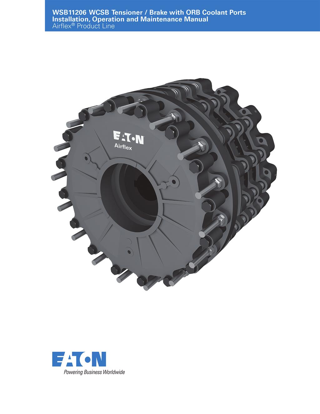
WCSB tensioner / brake with ORB coolant ports
|
|
|
- Bridget Dawson
- 6 years ago
- Views:
Transcription
1
2 General information!! Forward this manual to the person responsible for Installation, Operation and Maintenance of the product described herein. Without access to this information, faulty Installation, Operation or Maintenance may result in personal injury or equipment damage. Note: Part lists in this manual are specifically for WCSB assemblies that have cooling ports threaded to accept SAE O-ring boss type fittings. If you are maintaining a WCSB assembly that has cooling ports threaded to accept NPT fittings, refer to manual WSB for the appropriate part lists or contact the factory for additional information. Use Only Genuine Airflex Replacement Parts Eaton's Airflex division recommends the use of genuine Airflex replacement parts. The use of non-genuine Airflex replacement parts could result in substandard product performance, and may void your Eaton warranty. For optimum performance, contact Airflex: In the U.S.A. and Canada: (800) Outside the U.S.A. and Canada: (216) Internet: 2 EATON WSB11206 WCSB Tensioner / Brake with ORB Coolant Ports Installation, Operation and Maintenance Manual E-CLCL-II009-E August 2015
3 Table of contents Section Description Page No. Cutaway Drawing INTRODUCTION Description How It Works INSTALLATION Preparation Mounting Air System Coolant System OPERATION Conditions of Operation Pressure and Speed Limits Wear-in Procedures Operational Sequence Periodic Maintenance MAINTENANCE Wear Limits Wear Adjustment Disassembly Procedures Friction Material Replacement WC Wear Plate Replacement Cylinder Seal Replacement Spring Replacement Assembly Procedures Assembly Procedures ORDERING INFORMATION / TECHNICAL ASSISTANCE Equipment Reference PARTS Basic Assemblies 24WCSB Parts Basic Assemblies 36WCSB Parts Basic Assemblies 48WCSB Parts Sub-Assemblies (Standard) KITS End Plate & Pressure Plate Wear Plate Kits Reaction Plate Wear Plate Kits Cylinder Seal Kits (Spring Apply) Cylinder Seal Kits (Air Apply) Friction Disc Kits (Standard Water Cooled) Friction Disc Kits (Standard Air Cooled) Friction Disc Kits (Corrosion Resistant) AC Friction Disc Kit (Crossion Resistant) REVISION PAGE 39 EATON WSB11206 WCSB Tensioner / Brake with ORB Coolant Ports Installation, Operation and Maintenance Manual E-CLCL-II009-E August
4 A Figure 1 Item Description Item Description Item Description 6 Stud 23 Seal 7* Friction Disc Assembly 27 Spacer Tube 12 Clamp Tube 28 Gear 13 Pressure Plate S/A 29 Wear Spacer 16 Spring Housing 30* Reaction Plate S/A 17 Flat Washer 33 Dual Piston 18 Locknut 34 Reaction Spring 19 Cylinder 52 Inner Spring 20 Hex Head Screw 53 Spring Retainer 21 Seal 105 Pipe Plug 22 Outer Spring 106 Sleeve Nut * See Section 6.4 for sub-assembly illustrated part lists and component descriptions. Item Description 112 Mounting Flange / Cylinder 114 Seal 116* Pressure Plate S/A 117* End Plate S/A 118 Friction Disc 119 Disc 121 Flat Head Screw 122 Pipe Plug 124 Clamp Tube 125 Stop Plate 127 Pipe Plug 4 EATON WSB11206 WCSB Tensioner / Brake with ORB Coolant Ports Installation, Operation and Maintenance Manual E-CLCL-II009-E August 2015
5 1.0 INTRODUCTION Throughout this manual there are a number of HAZARD WARNINGS that must be read and adhered to in order to prevent possible personal injury and/or damage to the equipment. Three signal words "DANGER", "WARNING", and "CAUTION" are used to indicate the severity of the hazard, and are preceded by the safety alert symbol. Danger Denotes the most serious injury hazard, and is used when serious injury or death WILL result from misuse or failure to follow specific instructions. Used when serious injury or death MAY result from misuse or failure to follow specific instructions. Used when injury or product / equipment damage may result from misuse or failure to follow specific instructions. It is the responsibility and the duty of all personnel involved in the installation, operation and maintenance of the equipment on which this device is used to fully understand the Danger,, and, procedures by which hazards are to be avoided. 1.1 Description The Airflex WCSB water-cooled tensioner / brake assembly is designed for constant tension applications. It is exceptionally well suited for high inertia stop ping and rapid heat dissipation. The WCSB tensioner / brake assembly incorporates both an air applied water-cooled tensioner and an air cooled spring set brake into one relatively compact unit. The water-cooled section is used for high energy, constant slip tensioning, while the spring set brake serves as an emergency stopping or parking brake. The design of the WCSB tensioner / brake assembly permits mid-shaft or end-shaft mounting. The rugged construction ensures long, trouble free service WCSB tensioner / brake assemblies are available in various sizes and quantities of friction discs. The model number identifies the number of discs and the nominal disc diameter. For example, 324WCSB indicates three 24" diameter discs. Note that the air-cooled disc is typically larger in diameter by 2" when compared to the water- cooled disc, therefore, the model number will refer to the diameter of the water-cooled discs only. Additional notations are made in describing the model number to indicate the number of water-cooled (WC) disc assemblies and number of air cooled (AC) discs. For example, a 436WCSB (3WC/1AC) would indicate three water-cooled discs and one air cooled disc, whereas a 436WCSB (2WC/2AC) would indicate two watercooled and two air-cooled discs When size, such as 36WCSB, is referred to in this manual, it means that the information given applies to all models using the 36" diameter water-cooled disc assembly; i.e., 236WCSB, 336WCSB, etc All WCSB tensioner / brake assemblies referred to in this IOM have SAE O-ring Boss (ORB) ports for the coolant inlets and outlets. These ports utilize a straight thread and appropriately installed fittings have an O-ring for sealing versus the NPT tapered thread used previously and referred to in IOM WSB The ORB ports provide superior sealing properties and reduce the risk of damage to the brake during fitting installation The air applied pistons in the WCSB tensioner / brake assemblies are available in either single or dual piston designs. The WCSB tensioner / brake assemblies dual mounting flange / cylinder (112) and dual piston (33) assembly (112) offers precise tensioning control by dividing the piston / cylinder into inner and outer chambers that are isolated by intermediate seals (114). Also, for light tensioning loads, the inner chamber is used, not the outer chamber. See Figure 1. This provides the ability to improve fine modulation of clamping pressure on the tensioner discs and improved control over our standard single chamber design. For very light tensioning loads, the outer piston can be used solely, with no pressure applied to the inner piston. For the largest tensioning loads, both pistons can be used together. If it is desirable to operate the WCSB tensioner / brake assembly at maximum tensioning load and not utilize the precise tensioning feature, the WCSB tensioner / brake assembly can be ordered without the intermediate piston seal (114). EATON WSB11206 WCSB Tensioner / Brake with ORB Coolant Ports Installation, Operation and Maintenance Manual E-CLCL-II009-E August
6 1.1.6 WCSB tensioner / brake assemblies can be used with either closed loop or open loop water systems This manual includes metric equivalents usually shown in ( ) following the U.S. measurement system value. Be sure to use the correct value. 1.2 How It Works Referring to Figure 1, the gear (28) is mounted on the shaft which is to be stopped and the tensioner assembly is attached to the machine frame or a reaction bracket. Air pressure is first applied through the ports in the mounting flange / cylinder (112) causing the piston (33) to apply force to the pressure plate assembly (116). As air pressure is applied through the ports in the cylinder (19) on the spring set section of the unit, the cylinder and pressure plate (13), which are attached to each other with screws (20), flat washers (17) and spacer tubes (27), move away from the mounting flange (112), which is connected to the machine frame or reaction bracket. The pressure plate compresses the springs (22) and (53) against the stationary spring housing (16). As the pressure plate moves, the end plate subassembly (117) also moves away from the mounting flange / cylinder until it rests against the stop plates (125) which are axially fixed. The pressure plate (13) then continues to move away from the end plate subassembly and the clamp force is removed from the disc (119) that rides on the gear. As the end plate subassembly (117) moves towards the stop plates, the piston (33) and friction disc subassemblies (7) also move by means of the air pressure initially applied. Relieving the air pressure within the mounting flange / cylinder reduces the clamp force applied to the friction discs, allowing the shaft to be free to rotate. Modulation of the air pressure then controls applied torque of WCSB tensioner / brake assembly. As air pressure is exhausted from both the mounting flange / cylinder (112) and the cylinder (19), the springs force the pressure plate (13) toward the mounting flange, clamping the disc (119) between the pressure plate and the end plate subassembly (117). As the piston (33) retracts, the endplate subassembly continues to move towards the mounting flange / cylinder, pressing against the friction disc assemblies (7), reaction plate (30) and pressure plate subassembly (116). As the pressure plate (116) comes to rest against the mounting flange, the spring force clamps all discs between adjacent surfaces, applying stopping torque to the shaft. High heat dissipation within the tensioner section in the WCSB tensioner / brake assembly is accomplished by passing water through a special cavity behind copper alloy wear plates (3). 2.0 INSTALLATION Only qualified maintenance personnel should install, adjust or repair these units. Faulty workmanship will result in unreasonable exposure to hazardous conditions or personal injury. Read these instructions thoroughly and review until you fully understand the installation sequence before proceeding with the work described in this section. Failure to follow these instructions will result in unreasonable exposure to hazardous conditions or personal injury. Do not paint the clamp tubes (12), (124), wear spacers (29), or the springs (34), as this may hinder the engagement or disengagement of the WCSB tensioner / brake assembly. 6 EATON WSB11206 WCSB Tensioner / Brake with ORB Coolant Ports Installation, Operation and Maintenance Manual E-CLCL-II009-E August 2015
7 2.1 Preparation Refer to the appropriate assembly drawing (available upon request) for appropriate envelope dimensions, mounting register diameters, mounting bolt circles and positions, and stud support bracket recommendations for each specific WCSB tensioner / brake assembly The WCSB tensioner / brake assembly's reaction member should have a machined register to allow for mounting and alignment control of the WCSB tensioner / brake assembly and allow for full support of the face of the mounting flange / cylinder (112) For proper operation and service life, the WCSB tensioner / brake assembly reaction member must be aligned to the shaft within the limits shown in Table 1. Proper alignment is necessary to ensure that the friction discs track properly. Improper alignment will result in excessive wear to the friction material and mating surfaces, plus the gear and splined bore of the friction disc assemblies. See Figure 2. Table 1 Alignment Requirements Concentricity Perpendicularly (Parallel, TIR) of (Angular, TIR) of Shaft and Tensioner Mounting Flange to Size Inches (mm)shaft* Inches (mm) 24WCSB (0,25) (0,30) 36WCSB (0,25) (0,48) 48WCSB (0,25) (0,64) * Perpendicularity measured near the outside diameter of the mounting flange Refer to the appropriate assembly drawing for the setup dimension between the tensioner mounting surface and the end of the gear (dimension "A" on Figure 1). Gears should be positioned to ensure that when the tensioner is mounted the disc splines will not overhang the end of the gear when components are in both new and worn conditions. The gear is typically bored and keyed for a resulting Class FN2S interference fit for inch shafting and ISO System S7h6 for metric shafting. Contact Airflex Application Engineering for specific recommendations. 2.2 Mounting The WCSB tensioner / brake assembly must be mounted to a clean, rigid surface with hardened flat washers and screws of the grade, quantity, and size as listed in Table 2. Mounting to a properly aligned, rigid surface that fully supports the face of the mounting flange minimizes any deflection during operation and helps to ensure that the friction discs will track properly on the copper wear plates. Note: Before installing the gear (28) onto the shaft, slide it into the brake assembly to align the splines in the friction disc assemblies. Air pressure must be applied to the brake cylinder (19) to release the friction disc assemblies for alignment. Once the gear passes through all friction disc assemblies, exhaust the air to clamp them into position and remove the gear. Danger Use only the proper number and grade fasteners shown in Table 2. Use of commercial grade (Grade 2) fasteners where Grade 8 fasteners are specified may result in failure of the fasteners and a sudden and drastic reduction in brake torque. Water inlets and outlets must be located as close as possible to the 6 o clock and 12 o clock positions, respectively. This will prevent air pockets in the water cavity, which would allow the WCSB tensioner / brake assembly to overheat Ensure that the shaft is free of nicks or burrs and the key fits properly in the shaft and gear Apply a light coat of anti-seizing compound to the shaft and key. Tap the key into the shaft keyway. Correct Incorrect Figure 2 EATON WSB11206 WCSB Tensioner / Brake with ORB Coolant Ports Installation, Operation and Maintenance Manual E-CLCL-II009-E August
8 2.2.4 Heat the gear uniformly to 250 o F (121 o C) to expand the bore and ease assembly. Press the gear onto the shaft, making sure that the dimension between the gear and the tensioner mounting surface ("A") is maintained. See Figure 1. Allow the gear to cool Apply a thin coat of MOLUB-ALLOY 936 SF Heavy or equivalent grease to the splines of the gear Pre-fill the grease channel in the friction disc splines (if applicable) with MOLUB-ALLOY 936 SF Heavy or equivalent grease, as shown on Figure 3. Channel is filled with MOLUB-ALLOY 936 SF heavy grease Excessive lubricant may contaminate friction material, resulting in erratic response or loss of torque. The use of anti-seize or bearing greases on the gear splines may result in premature gear and disc spline wear..12" (3.0 mm) Figure Rig the WCSB tensioner / brake assembly into position and slide it over the gear. Avoid placing lifting straps or cables directly on the release springs (34). Table 2 Fastener Description and Assembly Torque - ft.-lb. (Nm) Item Description Specification 24WCSB 36WCSB 48WCSB 4 Wear Plate Screw Size 5/16-18 NC Gr. 8 3/8-16-NC2 Gr. 8 3/8-16-NC2 Gr. 8 5 Locknut Quantity Torque, Dry 21 (28) 40 (54) 40 (54) 18 Locknut Size 1 1/8-7 NC Gr /8-6 NC Gr /8-6 NC Gr Quantity Torque, Lubed 500 (677) 750 (1016) 750 (1016) 20 Hex Head Screw Size 1 1/8-7 NC Gr /8-6 NC Gr /8-6 NC Gr. 8 Quantity Torque, Lubed 500 (677) 750 (1016) 750 (1016) 57 WC Friction Size 1/2-13 NC Class 3 1/2-13 NC Class 3 1/2-13 NC Class 3 Disc Screw Quantity Torque, Loctite # (20) 15 (20) 15 (20) 121 Dry Friction Size 1/2-13 NC Class 3 1/2-13 NC Class 3 1/2-13 NC Class 3 Disc Screw Quantity Torque, Loctite # (27) 20 (27) 20 (27) Customer Mounting Size 5/8-11NC-2 Gr NC Gr /8-6NC Gr. 5 Supplied Screw Quantity Torque, Lubed 150 (203) 660 (895) 1100 (1490) Customer SAE Coolant Size SAE-12 SAE-20 SAE-20 Supplied Fittings Quantity* Torque, O-Ring Lube (92-105) ( ) ( ) *Note: Increase the quanity of SAE coolant fittings by 4 for each Reaction Plate S/A (30) in the WCBD tensioner/brake assembly. 8 EATON WSB11206 WCSB Tensioner / Brake with ORB Coolant Ports Installation, Operation and Maintenance Manual E-CLCL-II009-E August 2015
9 2.2.8 While supporting the WCSB tensioner / brake assembly, connect an air supply to the cylinder (19) and apply adequate pressure to release the WCSB tensioner / brake assembly. Attach the mounting flange (2) to the mounting surface using the appropriate fasteners. Tighten the fasteners to the specified torque value. See Table 2. Exhaust the air from the cylinder after tightening the fasteners. Maximum allowable air pressure in the cylinder (19) is 150 psig (10.2 bar) Some WCSB tensioner / brake assembly (typically 3 and 4 disc assemblies) require an additional support bracket to minimize torsional deflection during operation. Refer to the appropriate assembly drawing for bracket recommendations. The bracket, when required, will fit over the sleeve nuts (106) located on the studs (6) closest to the 6 o clock position. Secure the bracket onto the sleeve nuts with flat washers (17) and locknuts (18). Tighten the locknuts to the value listed in Table 2. Shim the base of the support bracket as required. Install and tighten fasteners as required to secure the bracket into position. Ensure that the support bracket does not interfere with or bind on the cylinder (19). Interferences could prevent the WCSB tensioner / brake assembly from properly engaging or releasing WCSB tensioner / brake assembly tensioners should be covered to protect the unit from dirt, rain, overspray, and other sources of external contamination. In extreme environments the use of a sealed enclosure with internal strip heater is recommended to prevent moisture from collecting on the unit. 2.3 Air System Operation of the WCSB tensioner / brake assembly at pressures exceeding those specified in Section 3.2 may result in damage to components. Minimum releasing pressure for the spring set brake should be observed. Operation at pressures below minimum will result in WCSB tensioner / brake assembly drag, excessive heat and wear, and damage to brake components. vented to atmosphere. Porting should be filtered to avoid contamination of the piston / cylinder during single piston actuation Maximum allowable pressure is 150 psig (10.2 bar) in the spring set brake cylinder (19), and 150 psig (10.2 bar) in the air applied mounting flange / cylinder (112). See Section 3.2 for other limitations Use only clean, filtered air (a 50 micron filter or better is recommended) which is free of excess moisture. Exhaust porting in dual pressure piston / cylinders should also be filtered to avoid contamination when open to atmosphere during single port actuation Air inlet sizes are shown in Table 3. Air inlets for the spring set brake are on the face of the cylinder (19). Air inlets for the air applied tensioner (radially located in the mounting flange) should be located at or near the 6 o clock position to facilitate purging of moisture that may accumulate in the air system. Table 3 Actuation Port Sizes Cylinder Mounting Flange MountingFlange Size (3 ports) (Small Piston) (Large Piston) 24WCSB 1/2"-14 NPT 1/4"-18 NPT 1/2"-14 NPT 36WCSB 3/4"-14 NPT 3/8"-18 NPT 3/4"-14 NPT 48WCSB 1"-11.5 NPT 1/2"-14 NPT 1"-11.5 NPT All pipes should be free of metal chips, cutting compound and any other foreign matter. Pipe ends should be reamed after cutting to eliminate possible restrictions. For optimum air system response, a minimum number of bends and elbows should be used The final connection to the brake inlet ports on the cylinder (19) must be made with flexible hose. If using only one inlet, connect the hose to the lowest position The WCSB tensioner / brake assembly does not require lubricated air; however associated control valves may. Consult the valve manufacturer for appropriate recommendations. When applying operating pressure to only one of two ports on units with dual pressure pistons (33), the second piston pressure port must be open and EATON WSB11206 WCSB Tensioner / Brake with ORB Coolant Ports Installation, Operation and Maintenance Manual E-CLCL-II009-E August

10 2.4 Coolant System An ORB port can be identified by the machined spot face and a chamfer (for sealing of the O-ring). See Figure 4. See Table 2 for the torque to values and the ORB fitting size associated with each WCSB tensioner / brake assembly Ensure the O-ring and back up washer on the SAE fitting are in the proper position on non-threaded section of the SAE fitting nearest to locknut Tighten the SAE fitting by hand into the threads of the ORB port until the back-up washer contacts the face of the ORB port To position the SAE fitting, unscrew the SAE fitting up to one full turn then hold the SAE fitting in desired position and tighten locknut so that the back-up washer contacts face of ORB port and forces the O-ring on the SAE fitting within the boss cavity. Tighten to the torque listed in Table 2. ORB Port Figure 4 Make sure that the water inlets and outlets are positioned as close as possible to the 6 o'clock and 12 o'clock positions, respectively. This will help to minimize the formation of air pockets in the water cavity during operation, which could contribute to overheating of the WCSB tensioner / brake assembly. Installation of NPT or other incompatible threaded piping or fittings into ORB ports will damage the ports, resulting in leakage or other failure Installation of straight SAE fittings Inspect the SAE fittings for damage and contamination Apply Molykote 55 O- ring lubricant to the O- ring on the SAE fitting Turn the SAE fitting into ORB port until finger tight, then apply the respective assembly torque. Refer to Table Installation of adjustable SAE fittings Inspect the SAE fittings for damage and contamination. When installing SAE fittings male NPT fittings are very similar in size to SAE threads and will engage in the female SAE threaded ports. If this is done the WCSB tensioner / brake assembly may be damaged! Only use SAE fittings in the coolant ports of the WCSB tensioner / brake assemblies Maximum allowable coolant pressure is 40 psig (3.1 Bar) for size 36WCSB and 48WCSB units and 45 psig for the 24WCSB. The use of an accumulator or pressure relief valve may be desirable to reduce the effect of pressure spikes in the coolant system during operation. Maximum allowable water pressure is dependent upon WCSB tensioner / brake assembly model. Applied pressure or surges exceeding maximum allowable may result in damage to the WCSB tensioner / brake assembly The coolant supply and discharge hose, pipe and fitting sizes, along with minimum flow rates for the WCSB tensioner / brake assembly's rated horsepower, are listed in Table Coolant supply connections to the tensioner should provide a parallel flow through each section of the tensioner. Series flow is not recommended, as it can lead to overheating of the WCSB tensioner / brake assembly Inlet and outlet coolant manifolds must be provided. Manifolds should be constructed to allow for even flow through all ports Apply Molykote 55 O- ring lubricant to the O- ring on the SAE fitting. 10 EATON WSB11206 WCSB Tensioner / Brake with ORB Coolant Ports Installation, Operation and Maintenance Manual E-CLCL-II009-E August 2015
11 Table 4 Coolant Supply Data Min Flow Rate Min Flow Rate Min Flow Rate Water Inlet and Min Flow GPM (dm 3 /min) GPM (dm 3 /min) GPM (dm 3 /min) Thermal Outlet Pipe Size Rate GPM 70% Water, 30% 60% Water, 40% 50% Water, 50% Rating (Minimum (dm 3 /min) Ethylene Glycol Ethylene Glycol Ethylene Glycol Model HP (kw) 1 piping I.D.) 100% Water 2 by vol. 3 by vol. 4 by vol (201) SAE-12 (3/4") 27 (102) 32 (121) 35 (132) 40 (151) (402) SAE-12 (3/4") 54 (204) 64 (242) 70 (265) 80 (303) (603) SAE-12 (3/4") 81 (305) 96 (361) 105 (395) 120 (451) (805) SAE-12 (3/4") 108 (406) 128 (481) 140 (526) 160 (602) (485) SAE-20 (1") 65 (246) 76 (288) 84 (318) 98 (371) (969) SAE-20 (1") 130 (489) 152 (572) 168 (632) 196 (737) (1454) SAE-20 (1") 195 (738) 228 (863) 253 (958) 294 (1113) (1937) SAE-20 (1") 260 (978) 304 (1143) 336 (1263) 392 (1474) (969) SAE-20 (1-1/4") 130 (489) 152 (572) 168 (632) 196 (737) (1937) SAE-20 (1-1/4") 260 (978) 304 (1143) 336 (1263) 392 (1474) (2906) SAE-20 (1-1/4") 390 (1467) 456 (1715) 504 (1895) 588 (2211) (3874) SAE-20 (1-1/4") 520 (1956) 608 (2286) 672 (2526) 784 (2948) 1. Thermal rating based on a 70 F (21 C) water inlet temperature and a 50 F (28 C) temperature rise between inlet and outlet HP/GPM, (1.97kw/(dm³/min)) HP/GPM, (1.68kw/(dm³/min)) HP/GPM, (1.53kw/(dm³/min)) HP/GPM, (1.31kw/(dm³/min)) Note: Minimum Flow Rates listed above are to achieve thermal rating. Lower flow rates are acceptable provided that they satisfy peak thermal requirement Use flexible connecting hose to each WCSB tensioner / brake assembly coolant section to allow axial travel of the pressure plate, reaction plate, and end plate during WCSB tensioner / brake assembly operation. Hose lengths running between the manifold and the inlet or outlet ports should be equal in length, if possible. Reductions in the recommended line diameter should be avoided to prevent excessive line pressures Avoid the use of sharp bends and elbows that will restrict water flow. Loops and bends in the lines may create air pockets, which substantially reduce the flow of coolant and can contribute to overheating Coolant and coolant supply lines should be free of foreign material (a 500 micron water filter is recommended). In the event that contaminated water is used as a coolant (not generally recommended), use of a multistage filter / strainer may be desirable to avoid the need for frequent cleaning of fine mesh filters Figure 5 illustrates a typical closed loop liquid to liquid coolant system. The heat exchanger and temperature control would be replaced with a radiator, fan and motor in a liquid to air system The coolant supply temperature at the inlet should be 100 o F (38 o C) or lower. The coolant outlet temperature should not exceed the values given in Table 5. However, in no event should there be more than a 50 o F (28 o C) temperature rise between inlet and outlet. See Table 5 for maximum allowable outlet coolant temperature with various water / ethylene glycol mixtures and other cooling media. Table 5 Maximum Inlet & Outlet Coolant Temperature Maximum Maximum Allowable Maximum Allowable Coolant Allowable Water/ Ethylene Coolant Inlet Outlet Coolant Glycol Mixture Temperature Temperature Temperature % by volume F ( C)* F ( C) Rise F ( C) 100/0 100 (38) 150 (66) 50 (28) 70/ (46) 165 (74) 50 (28) 60/ (46) 165 (74) 50 (28) 50/ (49) 170 (77) 50 (28) * Provided that temperature rise is no greater than 50 0 F (28C) EATON WSB11206 WCSB Tensioner / Brake with ORB Coolant Ports Installation, Operation and Maintenance Manual E-CLCL-II009-E August
12 Open Loop Systems For efficient operation of the WCSB tensioner / brake assembly, an adequate supply of filtered fresh water is required. (See section ). Excessive water hardness promotes the formation of scale deposits, which, in time, will affect the service life of the WCSB tensioner / brake assembly. Water of high acidity or high in corrosive salts may cause electrolytic corrosion between the dissimilar metals used in the water cavities. Water treatment should be considered if the properties of the water exceed the following: Equivalent calcium carbonate content hardness): Maximum 100 p.p.m. ph value: 7.0 to 9.0. Open loop systems should be thoroughly flushed with clean fresh water after operation to reduce the corrosive effects of contaminants on internal components Closed Loop Systems For efficient operation of the WCSB tensioner / brake assembly in a closed loop system, ethylene glycol coolant conforming to SAE Standard J1034 should be used. For preparation of the proper concentration of a water / ethylene glycol mixture, use make-up water which is low in corrosive ions such as chlorides and sulfates. Recommended ph value of the water / ethylene glycol glycol mixture: 7.5. to V Outlet mainfold V Triple Outlet manifold )( )( )( )( 16% 34% 34% 16% V Quad Outlet manifold Modulating valve Out Raw water In Strainer Pressure switch Centrifugal pump Temperature sensing bulb Heat exchanger Motor WC Inlet mainfold Pressure relief valve Temperature switch Single Outlet manifold )( )( 50% 50% V Dual Outlet manifold )( )( )( )( )( 12.5% 25% 25% 25% 12.5% Strainer Level switch )( )( )( 25% 50% 25% Reservoir Figure 5 12 EATON WSB11206 WCSB Tensioner / Brake with ORB Coolant Ports Installation, Operation and Maintenance Manual E-CLCL-II009-E August 2015
13 3.0 OPERATION 3.1 Conditions of Operation The following Hazard s are to be followed for proper WCSB functioning: Friction material must be worn in to achieve product torque rating. Verify proper operation before putting the product into service. See Section 3.3 for additional burnishing procedures. Protective means must be used to prevent oil, grease, dirt or coolant from coming into contact with the surfaces of the friction discs (8), (118), disc (119) or the wear plates (3). Oil or grease on these parts will significantly reduce the torque capacity of the WCSB tensioner / brake assembly. Dirt or coolant will produce erratic torque. Do not risk personal injury or damage to the equipment! Maximum free-wheeling speed must not exceed the speeds listed in Table 6. Exposure to speeds in excess of these values may cause the friction discs (8) to burst and result in extensive damage to the tensioner and / or cause personal injury. For proper cooling of the WCSB tensioner / brake assembly, it is required that the coolant inlet is located as close as possible to the 6 o clock position and the outlet is located near the 12 o clock position. This will help to assure that all coolant cavities are water-filled to help avoid over-heating. For operation in subfreezing temperatures, ethylene glycol antifreeze must be added to the water. The antifreeze content of the mixture is critical and should not exceed 50% by volume. Excessive amounts of antifreeze will reduce cooling capacity and can cause coolant leakage due to overheating. Refer to Table 5. Maximum ambient temperature is 110 o F (43 o C). Minimum ambient temperature for closed loop systems using ethylene glycol antifreeze is 0 o F (-18 o C).For open loop systems using water, the minimum temperature is 45 o F (7 o C). Table 6 Maximum Disc Speeds Maximum Maximum Free Slip Speed Wheeling Speed Size RPM RPM 24WCSB WCSB WCSB Pressure and Speed Limits Maximum allowable coolant pressure is 40 psig (2.8 bar) for the 36WCSB and 48WCSB tensioner / brake assemblies and 45psgi (3.1 bar) for the 24WCSB tensioner / brake assembly. The use of an accumulator or pressure relief valve may be desirable to reduce the effect of pressure spikes in the coolant system during operation. Maximum allowable water pressure is dependent upon WCSB tensioner / brake assembly model. Applied pressure or surges exceeding maximum allowable may result in damage to the WCSB tensioner / brake assembly Maximum slip speeds and free-wheeling disc speeds are shown in Table 6. Excessive slip speeds will result in rapid friction material wear. For good life, the values in Table 9 should not be exceeded Maximum allowable pressure is 150 psig (10.2 bar) in the spring set brake cylinder (19). Refer to the assembly drawing (available on request) for minimum pressure required for full release of the spring set brake. Release pressure is dependent upon the quantity of springs (22) (52) used in the specific brake Maximum allowable pressure within the air applied tensioner mounting flange / cylinder (112) is 150 psig (10.2bar). Maximum operating pressure is specified on the assembly drawing mentioned in section before EATON WSB11206 WCSB Tensioner / Brake with ORB Coolant Ports Installation, Operation and Maintenance Manual E-CLCL-II009-E August
14 3.3 Wear-in Procedures In order to improve initial operation and brake torque, it is suggested that the non-asbestos friction material used in WCSB tensioner / brake assembly be worn-in prior to normal operation to improve contact of the mating friction surfaces. Machine operation should be monitored closely until the friction material wears in The shaft on which the brake discs are mounted should be free to rotate to allow for run-in. On drawworks applications, disconnect the wire rope from the drawworks drum to allow operation as described in the following paragraphs Ensure that the coolant system is operating prior to dynamic operation of the WCSB tensioner / brake assembly. Verify that coolant temperature, pressure and flow values are within required settings or limits during operation. Dynamic operation of the WCSB tensioner / brake assembly including while in the fully released condition is not recommended without proper coolant flow in the WCSB tensioner / brake assembly. Heat generated during operation could result in damage to WCSB tensioner / brake assembly components Release the brake by applying full release pressure through the ports in the cylinder (19) to allow the brake to freely rotate. Apply no pressure to the tensioner pressure ports in the mounting flange/cylinder (112) Run the motor to achieve a brake disc speed listed in Table 6. Exhaust the air pressure in the brake rapidly to 90 psig (6.1 Bar). Slip the brake for the time specified in Table 7, but DO NOT ALLOW THE BRAKE TO SLIP FOR MORE THAN THE TIME SPECIFIED. Slipping the WCSB tensioner / brake assembly at increased time intervals, speeds or pressures other than specified will result in damage to WCSB tensioner / brake assembly components After the WCSB tensioner / brake assembly has engaged / slipped for upto the maximum slip time specified in Table 7, quickly apply full air pressure to completely release the WCSB tensioner / brake assembly. Smoke rising from the brake should be expected. Freewheel the brake discs at the speed listed in Table 7, allowing the brake disc (119) to cool to a temperature below 120 o F (48 o C). The use of fans or clean, dry compressed air can be used to accelerate the cooling process. Use proper safety precautions when using forced ventilation. Table 7 Wear-in Parameters Operating Slip Time Wear-in Cycles Size Speed (RPM) (Seconds) Required 24WCSB WCSB WCSB Monitor the brake disc (119) temperature after slipping and cooling. Do not allow the brake disc temperature to exceed 180 o F (82.2 o C) Repeat steps thru for the number of cycles shown in Table 7 to allow for adequate wearin of the air-cooled brake. Allow the brake disc to completely cool to ambient temperature prior to testing the torque capacity of the brake or returning it to service. 3.4 Operational Sequence Ensure that the coolant system is operating prior to dynamic operation of the WCSB tensioner / brake assembly. Verify that coolant temperature, pressure and flow values are within required settings or limits during operation. Dynamic operation of the WCSB tensioner / brake assembly including while in the fully released condition is not recommended without proper coolant flow in the tensioner. Heat generated during operation could result in damage to brake components. 14 EATON WSB11206 WCSB Tensioner / Brake with ORB Coolant Ports Installation, Operation and Maintenance Manual E-CLCL-II009-E August 2015
15 3.4.2 Air pressure is first applied through the ports in the mounting flange / cylinder (112) to apply force to the piston (33) in the WCSB tensioner / brake assembly. Adequate pressure should be applied to support the load the WCSB tensioner / brake assembly is controlling. Air pressure is then applied through the ports in the cylinder (19) on the spring set section of the WCSB tensioner / brake assembly, until it is fully released. Observe all pressure and speed limits while operating the WCSB tensioner / brake assembly. See Section After release of the spring set brake, slowly relieve the air pressure within the mounting flange / cylinder (112) to reduce the clamp force applied to the friction disc assemblies (7), allowing the shaft to rotate. Modulation of the air pressure will vary the applied torque of the WCSB tensioner / brake assembly. Modulation control is dependent upon the specific pneumatic control system used. Refer to the manufacturers information for operation of control valves or feedback systems WCSB tensioner / brake assembly with dual pressure pistons (33) provide a more finite range of control. Each chamber within the dual pressure piston can be pressurized independently or simultaneously. When applying or exhausting operating pressure to only one of two ports on units with dual pressure pistons (33), the second piston pressure port must be open/vented to atmosphere. Open ports should be filtered to avoid contamination of the piston and cylinder during piston operation Exhausting air pressure from the cylinder (19) of the spring set brake allows it to engage. Air pressure within the mounting flange / cylinder (112) can be exhausted simultaneously with that in the cylinder (19). For more rapid brake response, exhaust the air pressure in the mounting flange / cylinder (112) after engaging the spring set brake. Rapid engagement of a fully released WCSB tensioner / brake assembly could result in pressure spikes within the coolant cavities and subsequent leakage. 3.5 Periodic Maintenance As the friction material wears, adjustment of the brake may be required to keep pistons and cylinders within the proper stroke range. See the MAINTENANCE section for wear adjustment procedures and component wear limits Periodically check for external air leakage in the area of the piston seals (21) (23), and internal leakage across the dual pressure piston seals (114). For replacement, refer to procedures in Section 4.6, Maintenance Moisture that may accumulate in the brake cylinder can be purged on size all WCSB tensioner / brake assemblies. With air pressure exhausted from the cylinder, remove the pipe plug (105) at the 6 o clock position on the cylinder, and apply low air pressure to assist in expelling any excess moisture. After draining the cylinder, reinstall the pipe plug, applying a pipe thread sealant on the threads prior to installation. Applied air pressure greater than 10 psig (.69 Bar) should not be used when draining the cylinder. Use adequate shielding to avoid contact with direct spray from moisture being purged from the cylinder Periodically observe the discs while the brake or tensioner is fully released. Dragging discs may be caused by wear or contamination of the gear or disc splines, disc imbalance, warped discs, or misalignment. Correct as required Pneumatic and electrical control interlocks should be periodically checked for proper settings and operation. Note: The spring set brake is intended for parking or emergency braking only. Dynamic braking with the air cooled, spring set brake is not recommended except for emergency stopping situations or during initial wear-in. High heat generated during dynamic braking can result in damage or failure of the WCSB tensioner / brake assembly's components. EATON WSB11206 WCSB Tensioner / Brake with ORB Coolant Ports Installation, Operation and Maintenance Manual E-CLCL-II009-E August
16 3.5.6 If leakage or blockage of any water-cooled chamber is suspected, a static or dynamic test may be performed as follows: Static Pressure Test (a) Release the spring set brake by applying the proper air pressure, Dynamic Flow Test (a) Dynamic flow testing of the WCSB tensioner / brake assembly should be conducted at the required flow rate for the rated HP dissipation and coolant quality, as given in Table 4. Inlet pressure for the appropriate WCSB tensioner / brake assembly model is not to be exceeded. (b) (c) Ensure that the machinery will remain in a safe position prior to releasing the WCSB tensioner / brake assembly. Bleed all air from within the coolant cavity. Air bleeding must be accomplished by running coolant through the cavity with the tensioner secured in its proper operating position. Note: Avoid contaminating the friction material with coolant or water. Contamination of the friction material could result in erratic or loss of torque. After the air has been removed, install a pipe plug(s) in the outlet(s) and apply maximum allowable coolant pressure measured at the inlet to the water cavity. Maximum allowable is 40 psig (2.7 bar) for size 36WCBS and 48WCSB tensioner / brake assemblies, and 45 psig (3.0 bar) for the 24WCSB tensioner / brake assembly. Maintain this pressure for 30 minutes. Check for leakage at O.D. and I.D. sealing areas. Be sure to apply and retain air pressure to the cylinder (19) of the WCSB tensioner / brake assembly to release the spring pressure on the WCSB tensioner / brake assembly during static coolant pressure testing. Engagement of the brake during testing could develop surge pressures exceeding the maximum allowable within the coolant cavities resulting in possible damage to the seals. (b) There should be no restrictions on the outlet side of the WCSB tensioner / brake assembly to cause any backpressure to the unit. Coolant inlet and outlet sizes are listed in Table 4. Full size hoses and piping should be used. Check for low flow and / or leakage at the O.D. and I.D. seal areas. 4.0 MAINTENANCE Before doing any maintenance work on the WCSB tensioner / brake assembly, make sure that the machinery will remain in a safe position. Failure to do so could result is serious injury or possibly death. Only qualified maintenance personnel should install, adjust or repair these WCSB tensioner / brake assembly. Faulty workmanship will result in unreasonable expo- sure to hazardous conditions or personal injury. Read these instructions thoroughly and review until you fully understand the parts replacement steps before proceeding with the work described in this section. Failure to follow these instructions can result in unreasonable exposure to hazardous conditions or personal injury. 16 EATON WSB11206 WCSB Tensioner / Brake with ORB Coolant Ports Installation, Operation and Maintenance Manual E-CLCL-II009-E August 2015
17 4.1 Wear Limits Periodically examine the WCSB tensioner / brake assembly for wear of friction material, discs and wear plates. Failure to perform this examination will result in excessive wear, a significant reduction in torque, and may result in personal injury and / or damage to the machinery Wear limits for the WCSB tensioner / brake assembly's components are shown in Table 8. If any wear limit has been reached or exceeded, that component must be repaired or replaced. 4.2 Wear Adjustment Wear adjustment is periodically required as the friction material and mating surfaces wear. Wear adjustment reduces the running clearances between these surfaces to help maintain the holding force of the brake (for the spring applied feature), and to maintain the responsiveness of the brake by limiting the travel of components. Mechanical limits within the brake design require that the brake be adjusted when the adjustment points listed in Table 8 have been reached. Failure to perform adjustments when required may result in loss of adequate brake torque and potential injury to personnel or damage to equipment. Be certain to inspect the brake periodically to evaluate for wear, and adjust as necessary WCSB tensioner / brake assembly Inspection and Evaluation To determine when WCSB tensioner / brake assembly adjustment is required, the WCSB tensioner / brake assembly should be evaluated as follows: Visually inspect for friction material wear. The friction material is fully worn when the wear has reached the bottom of the wear groove or notch as shown in Figure 6. Note: Friction blocks for the air cooled brake in 48WCSB tensioner / brake assemblies have a step on the outer edge of the friction material rather than a wear groove. The material is fully worn when wear has reached the step on the outer edge of the friction material. See Figure 6a. Note: If fully worn replace the material and evaluate the condition of the mating wear surface. Note: If the wear limits of any of the friction discs or blocks have not been reached, determine if brake adjustment is required by proceeding to the next steps. Dust/wear Grooves 24WCSB & 36WCSB Figure 6 Wear surface Step Figure 6A 48WCSB Mounted surface EATON WSB11206 WCSB Tensioner / Brake with ORB Coolant Ports Installation, Operation and Maintenance Manual E-CLCL-II009-E August
18 Table 8 Wear Limits for WCSB Components - inches (mm) Item Component Description Wear Limit/Remarks Original Sizes/Remarks 3 Wear Plate Friction Wear Brake Size: Maximum Wear: Wear will be in the form of even wear or Signature 24WCSB (1,14) circular grooves in the copper surface. 36WCSB (1,27) 48WCSB (1,52) 8 Friction Disc Friction Material Fully worn at the bottom of the dust Brakes have adjustment provision. groove or wear notch on the 48WCSB. See Section Friction Disc Gear Backlash Maximum total backlash is (1.5). If step is worn in gear, gear must be 28 Core & Gear, replaced. 119 and Disc 12 Clamp Tube Reaction Area Maximum wear is (0.38). Wear will be in the form of notch or step on the side of tube. Reaction Holes Wear will be in the form of elongation of Original Reaction Hole and Bushing Sizes: 31 Reaction Plate the holes. Brake Size: Bore Size: 14 Pressure Plate Maximum wear is (0.80). 24WCSB (42,88) 117a End Plate 36WCSB (52,45) 48WCSB (60,33) 19 Cylinder Seal Area Maximum wear is (0.13). Wear will be in form of grooves where the seals contact the cylinder wall. 22 Spring Spring Free Height Springs must be replaced in complete sets. WCSB Brake Size: Minimum Free Height: WCSB Brake Size: Original Free Height: (124,46) (131,57) (161,8) (168,91) (222,25) (228,6) 34 Spring Spring Free Height WCSB Brake Size: Minimum Free Height: WCSB Brake Size: Original Free Height: (98,55) (101,6) (98,55) (101,6) (123,19) (127,6) 52 Spring Spring Free Height WCSB Brake Size: Minimum Free Height: WCSB Brake Size: Original Free Height: (125,73) (101,6) (165,1) (101,6) 119 Friction Disc Friction Material Maximum wear is (1,12) per surface. WCSB Brake Size: Original Thickness: (0.09 (2,24)Total) (25,4) (31,7) (31,7) Measure for WCSB tensioner / brake assembly wear: (a) Ensure that the load that the WCSB tensioner / brake assembly supports will be properly secured from possibility of movement when no pressure is being applied to the brake(s) being inspected. (c) Verify that the air pressure has been fully exhausted from these chambers by checking any in-line gauges (they should read zero pressure), and also by inspecting specific gaps between components as noted below. Refer to Figures 6 and 6A for the corresponding gap locations. (b) Exhaust all air pressure from the pressure chambers on both ends of the WCSB tensioner / brake assembly being evaluated. Pressurized areas are located in the Cylinder (19) and Mounting Flange (112). If more than one WCSB tensioner / brake assembly is used in the driveline, exhaust all air pressure from those brakes also. Note: Follow the recommendations of the control system manufacturer to ensure that no air pressure is trapped in the brake or control system, and that the control system has been safely isolated from the WCSB tensioner / brake assembly while performing inspections. Pressure in the cylinder (19) has been exhausted if the measured gap Z is greater than zero, and there is no clearance between each side of the disc (119) and the corresponding friction material. Pressure in the mounting flange (112) has been exhausted if gap Z-2, located between the mounting flange and the pressure plate (116) is closed and gap W is greater than zero. 18 EATON WSB11206 WCSB Tensioner / Brake with ORB Coolant Ports Installation, Operation and Maintenance Manual E-CLCL-II009-E August 2015
19 The Y gaps are measurements between the various wear plate sub-assemblies and are used to help evaluate the wear of the water- cooled friction discs and wear plates. These gaps will decrease as the WCSB tensioner / brake assembly wears. The wear limit for each of the Y gaps is the same for Y-1, Y-2 or Y-3. Y-1 0 pt Y-2 Y-3 Figure 7 W X Z1 Y-1 is the measurement between the mounting flange (116) and the reaction plate (30). Y-2 is the measurement between the reaction plate (30) and the adjacent reaction plate. The Y-2 gap is found only on WCSB tensioner / brake assembly that have three or more water- cooled discs. Y-3 is the measurement between the reaction plate (30) and the end plate (117). e) Record the W, X, Y-1, Y-2, and Y-3 values measured for each of the gaps, and compare them against the values listed in Table 9. Z-2 Figure 7A f) If the value measured for any Y gap (Y-1, Y-2, Y3) is equal to or less than the Y min value, the WCSB tensioner / brake assembly should be removed from service and repaired with new wear components. (d) Measure gaps between the components at positions W, X, Y-1, and if applicable, Y-2, and Y-3. See Figures 6, and 6a for the location of those gap positions. For reference: The W-gap is the measurement between the end plate (117) and the stop plates (125) and is used to determine when adjustment of the water-cooled section of the WCSB tensioner / brake assembly is required. This gap will increase as the WCSB tensioner / brake assembly wears. The X-gap is the measurement between the end plate (117) and the pressure plate sub-assembly (13) and is used to deter- mine when adjustment of the air-cooled section of the WCSB tensioner / brake assembly is required. This gap will decrease as the WCSB tensioner / brake assembly wears. g) If the value measured for all Y gaps (Y-1, Y-2 or Y-3) is greater than the Y min value, proceed to evaluate the measurement for gap W as follows: h) If the measurement for gap W is equal to or greater that the Wadjust value shown on Table 8, wear adjustment is required. Adjust the WCSB tensioner / brake assembly per the procedures listed in section If it is found that no wear spacers (29) exist between the clamp tube (12) and stop plate (125) before adjustment is attempted, all wear adjustments have been previously performed in the water-cooled section of the WCSB tensioner / brake assembly and brake overhaul is required. i) If the gap measured for gap X is equal to or less than the Xadjust value, wear adjustment is required. Adjust the WCSB tensioner / brake assembly per the procedures listed in section If it is found that no wear spacers (29) exist between the clamp tube (124) and stop plate (125), all wear adjustments have been previously performed in the air-cooled section of the brake and replacement of the friction discs (118) and disc (119) may be required. Remove the WCSB tensioner / brake assembly from service and evaluate the condition of those components, using Table 9 as a reference. EATON WSB11206 WCSB Tensioner / Brake with ORB Coolant Ports Installation, Operation and Maintenance Manual E-CLCL-II009-E August
WCSB tensioner/brake. General information. Warning. Caution
 General information!! Forward this manual to the person responsible for Installation, Operation and Maintenance of the product described herein. Without access to this information, faulty Installation,
Installation, Operation and Maintenance of Airflex Model WCSBEP* Tensioner / Brake (for size 36EP)
") WSB 11205 Forward this manual to the person responsible for Installation, Operation and Maintenance of the product described herein. Without access to this information, faulty Installation, Operation or
WSB 11205 Forward this manual to the person responsible for Installation, Operation and Maintenance of the product described herein. Without access to this information, faulty Installation, Operation or
WCB WCBD3 Water Cooled Tensioner - Installation, Operation and Maintenance Manual Airflex Product Line
 WCB 11080 WCBD3 Water Cooled Tensioner - Installation, Operation and Maintenance Manual Airflex Product Line General Information Forward this manual to the person responsible for Installation, Operation
WCB11070 WCB2 Tensioner/Brake Installation, Operation and Maintenance Manual Airflex Product Line
 WCB11070 WCB2 Tensioner/Brake Installation, Operation and Maintenance Manual Airflex Product Line 204182 General Information!! Forward this manual to the person responsible for Installation, Operation
Installation, Operation and Maintenance of the Airflex WCB2 Tensioner / Brake
 WCB 11070 Warning Forward this manual to the person responsible for Installation, Operation and Maintenance of the product described herein. Without access to this information, faulty Installation, Operation
Installation, Operation and Maintenance of Airflex Model WCB2EP* Tensioner / Brake (for size 36EP)
") WCB 11075 Forward this manual to the person responsible for Installation, Operation and Maintenance of the product described herein. Without access to this information, faulty Installation, Operation or
WCB 11075 Forward this manual to the person responsible for Installation, Operation and Maintenance of the product described herein. Without access to this information, faulty Installation, Operation or
FHB 8110 Brake Assemblies Installation, Operation and Maintenance Manual Airflex
 FHB 8110 Brake Assemblies Installation, Operation and Maintenance Manual Airflex General Information Forward this manual to the person responsible for Installation, Operation and Maintenance of the product
Section Description Page
 Table of contents IOM part number: 204107 Rev. A Section Description Page 1.0 INTRODUCTION 5-6 1.1 Description 5 1.2 How it works 5-6 2.0 INSTALLATION 6-7 2.1 Preparation 6-8 2.2 Mounting 7 2.3 Actuating
DBB Brake Assemblies. General Information. Warning. Caution
 General Information! Warning! Forward this manual to the person responsible for Installation, Operation and Maintenance of the product described herein. Without access to this information, faulty Installation,
Airflex DBBS Brake Assemblies Installation, Operation and Maintenance Manual DBB 8110
 Airflex DBBS Brake Assemblies Installation, Operation and Maintenance Manual DBB 8110 General Information Forward this manual to the person responsible for Installation, Operation and Maintenance of the
Installation, Operation and Maintenance of Airflex Model DBB Brake Assemblies
 DBB 8100 Warning Forward this manual to the person responsible for Installation, Operation and Maintenance of the product described herein. Without access to this information, faulty Installation, Operation
Installation, operation and maintenance of Airflex DBA brake assemblies DBA 8080
 Installation, operation and maintenance of Airflex DBA brake assemblies DBA 8080 ! Warning Forward this manual to the person responsible for Installation, Operation and Maintenance of the product described
Installation, Operation and, Maintenance of DBBS Brake Assemblies with the Plate Style Disc Centering Option
 DBB8112 A! Warning Forward this manual to the person responsible for Installation, Operation and Maintenance of the product described herein. Without access to this information, faulty Installation, Operation
Airflex DPA Caliper Brake CA Installation, operation and maintenance manual
 CA 10020 Installation, operation and maintenance manual 204204 General information!! Forward this manual to the person responsible for Installation, Operation and Maintenance of the product described herein.
Installation, Operation and Maintenance of the Airflex CH Multiple-Disc Clutch and Brake Assemblies
 HY 13100 Forward this manual to the person responsible for Installation, Operation and Maintenance of the product described herein. Without access to this information, faulty Installation, Operation or
Installation, Operation and Maintenance of Airflex Quick Release Valve
 QRV 9100 Forward this manual to the person responsible for Installation, Operation and Maintenance of the product described herein. Without access to this information, faulty Installation, Operation or
Airflex Air Cooled Disc Clutches and Brakes
 Airflex Air Cooled Disc Clutches and Brakes DBA Description... 183 DBA Brake Elements... 185 DBA Technical information... 186 DBB and DBBS Description... 187 DBB Brake Elements... 189 DBB Technical Information...
QRV 9100 Airflex Quick release valve Installation, operation and maintenance of Airflex Quick release valve
 Airflex Quick release valve 203977 Installation, operation and maintenance of Airflex Quick release valve Table of Contents Section Description Page No. AIRFLEX QUICK RELEASE VALVE 3 1.0 INTRODUCTION 4
CALIPER BRAKE INSTALLATION AND MAINTENANCE MANUAL
 CALIPER BRAKE INSTALLATION AND MAINTENANCE MANUAL WPT Power Corporation 1600 Fisher Road - Wichita Falls, TX 76305 P.O. Box 8148 - Wichita Falls, TX 76307 Ph. 940-761-1971 Fax 940-761-1989 www.wptpower.com
Instruction Manual for HSPA Take-Up Units
 Installation Instruction Manual for HSPA Take-Up Units Warning: To ensure the drive is not unexpectedly started, turn off and lockout the power source before proceeding. Failure to observe these precautions
Installation, Operation and Maintenance of Airflex Model DBBS Brake Assemblies
 DBB 8110 Warning Forward this manual to the person responsible for Installation, Operation and Maintenance of the product described herein. Without access to this information, faulty Installation, Operation
Installation, Operation and Maintenance of Airflex 229 DBA Brake Assemblies with Cone-style Disc Centering Option
 DBA 8081 Warning Forward this manual to the person responsible for Installation, Operation and Maintenance of the product described herein. Without access to this information, faulty Installation, Operation
Fisher 657 Diaphragm Actuator Sizes and 87
 Instruction Manual 657 Actuator (30-70 and 87) Fisher 657 Diaphragm Actuator Sizes 30 70 and 87 Contents Introduction... 1 Scope of Manual... 1 Description... 2 Specifications... 2 Installation... 3 Mounting
Installation, Operation and Maintenance of Airflex Models AD, ADP, BD and FDA Rotorseals
 RS 9040 Warning Forward this manual to the person responsible for Installation, Operation and Maintenance of the product described herein. Without access to this information, faulty Installation, Operation
Installation, Operation and Maintenance of Airflex Model AMCB AccuStop TM Clutch\Brake Combination
 AMCB 16200 Forward this manual to the person responsible for Installation, Operation and Maintenance of the product described herein. Without access to this information, faulty Installation, Operation
DeZURIK " BAW AWWA BUTTERFLY VALVES WITH EPOXY-RETAINED SEAT
 DeZURIK 20 144" BAW AWWA BUTTERFLY VALVES WITH EPOXY-RETAINED SEAT Instruction D10373 April 2017 Instructions These instructions provide information about the 20 (250 F2 model only) and the 24-144 BAW
Airflex. Airflex DBB & DBA Brakes
 36191_12pg Covers 8/11/03 6:06 PM Page 01 Airflex Airflex DBB & DBA Brakes These spring-applied, pressure released, disc style brakes develop equal torque in either direction of rotation. Their torque
Maintenance Manual 3-INCH INTERNAL VALVE F660 SERIES
 Maintenance Manual 3-INCH INTERNAL VALVE F660 SERIES REVISION 1.1 03/15/2002 LIST OF EFFECTIVE PAGES On a revised page, the portion of text or illustrations affected by the change is indicated by a vertical
OVERLOAD CLUTCHES FOR INDEX DRIVES
 The Driving Force in Automation OVERLOAD CLUTCHES FOR INDEX DRIVES WARNING WARNING This is a controlled document. It is your responsibility to deliver this information to the end user of the CAMCO indexer.
SERIES G3DB/AG3DB ELEVATOR
 TM INSTRUCTIONS AND PARTS LIST SERIES G3DB/AG3DB ELEVATOR WARNING This manual, and GENERAL INSTRUCTIONS MANUAL, CA-1, should be read thoroughly prior to pump installation, operation or maintenance. SRM00059
INSTRUCTION MANUAL AND PARTS LIST FOR SERIES 8L-630J AND 630M WARNING
 INSTRUCTION MANUAL AND PARTS LIST FOR SERIES 8L-630J AND 630M WARNING READ CA-l AND TIDS INSTRUCTION MANUAL PRIOR TO INSTALLATION, OPERATION OR MAINTENANCE WARNING This Instruction Manual and General Instructions
Maintenance Manual. 3-Inch Internal Valve. F660 Series
 3-Inch Internal Valve F660 Series LIST OF EFFECTIVE PAGES On a revised page, the portion of text or illustrations affected by the change is indicated by a vertical line in the outer margin of the page.
MAINTENANCE MANUAL FOR THERMOSTATIC TEMPERATURE REGULATING VALVE TRAC STYLE P
 MANUAL NUMBER P-EFS-1 MAINTENANCE MANUAL FOR THERMOSTATIC TEMPERATURE REGULATING VALVE TRAC STYLE P TRAC Regulator Company Inc. 160 South Terrace Avenue Mount Vernon, New York USA 10550-2408 Phone: (914)
Operation and Maintenance. S100 Series Centrifugal Fire Pumps. Table of Contents. Visit us at F /22/02 6/21/18
 S100 Series Centrifugal Fire Pumps Operation and Maintenance Form No. F-1031 Section 2117 Issue Date 02/22/02 Rev. Date 6/21/18 Table of Contents Safety Information-----------------------------------------------
INSTALLATION MANUAL. MB-180, MB-210 and MB-210L Motor Brake INSTALLATION. Force Control Industries, Inc. DESCRIPTION OPERATION
 MB-180, MB-210 and MB-210L Motor Brake INSTALLATION MANUAL 512-180-001-00 DESCRIPTION Posistop Motor Brakes are multiple surface, spring activated, pneumatic release braking devices that effectively dissipate
DODGE USAF 200/300 Direct Mount Pillow Block Bearings
 DODGE USAF 200/300 Direct Mount Pillow Block Bearings These instructions must be read thoroughly before installation or operation. This instruction manual was accurate at the time of printing. Please see
Temperature Sensor Series
 GENERAL DESCRIPTION The patented* No. 85026-Series Temperature Sensor contains a two-position valve operated by temperature variations around the integral sensing bulb. It is used to vent or block a pneumatic
HEVC Installation, operation and maintenance manual Airflex HEVC
 - Installation, operation and maintenance manual Airflex HEVC 5005 204261 General information Warning Forward this manual to the person responsible for Installation, Operation and Maintenance of the product
Installation,Operation, and Lubrication Instructions SPEED REDUCERS ILDE-00 TYPE DE ENGINEERING SERVICE BULLETIN
 ENGINEERING SERVICE BULLETIN ILDE-00 D-90 TYPE DE SPEED REDUCERS Installation,Operation, and Lubrication Instructions This Engineering Service Bulletin is designed to enable users to obtain the best possible
INSTALLATION AND MAINTENANCE MANUAL
 TYPE 2 PTO INSTALLATION AND MAINTENANCE MANUAL P.O. Box 8148 Wichita Falls, Texas 76307 1600 Fisher Rd. Wichita Falls, Texas 76305 Phone: (940) 7611971 Fax: (940) 7611989 www.wptpower.com email: info@wptpower.com
for Installation, Operation and Maintenance of Airflex CS and CSA Brake Assemblies CS 8000 Warning Forward this manual to the person responsible
 CS 8000 Warning Forward this manual to the person responsible for Installation, Operation and Maintenance of the product described herein. Without access to this information, faulty Installation, Operation
Eclipse GEN 2.0 CAFSystem, Model 150-ESECL as used with TC20 Series PTO Installation Instructions
 Eclipse GEN 2.0 CAFSystem, Model 150-ESECL as used with TC20 Series PTO Installation Instructions Read Read through the the safety installation information instructions overhaul carefully instructions
Thomas Disc Couplings Installation and Maintenance Series 52 Sizes with classical disc pack TM (Page 1 of 10) DANGER!
 DANGER!") Thomas Disc Couplings Installation and Maintenance Series 52 Sizes 125-925 with classical disc pack TM (Page 1 of 10) This is the Original Document in English Language Figure 1-1. General Information Thomas
Thomas Disc Couplings Installation and Maintenance Series 52 Sizes 125-925 with classical disc pack TM (Page 1 of 10) This is the Original Document in English Language Figure 1-1. General Information Thomas
Technical Manual MSI Hydraulic Adjustable Choke
 Technical Manual MSI Hydraulic Adjustable Choke MSI A Division of Dixie Iron Works, Ltd. 300 W. Main St. Alice, TX 78332 www.diwmsi.com (800) 242-0059 Revision A TABLE OF CONTENTS SECTION 1 WARNINGS...
INSTALLATION MANUAL. MB-250, MB-280 and MB-320 Motor Brake INSTALLATION. Force Control Industries, Inc. DESCRIPTION OPERATION
 MB-250, MB-280 and MB-320 Motor Brake INSTALLATION MANUAL 512-250-001-00 DESCRIPTION Posistop Motor Brakes are multiple surface, spring activated, pneumatic release braking devices that effectively dissipate
PRODUCT SERVICE MANUAL
 PRODUCT SERVICE MANUAL FOR AM322ICX-325AE, 350AN and 400A PUMPS WARNING This Special Instruction Manual and General Instructions Manual, SRM00046, should be read thoroughly prior to pump installation,
PO Box 645, Stockton, Missouri, FAX superiorgearbox.com
 I000-7000-D0447-A 4/7/05 1 SAFETY PRECAUTIONS CAUTION Please read this entire document prior to operating the gear drive. Gear drive failure and / or injury to operators may be caused by improper installation,
DODGE USN 500 and 600 Series Adapter Mount & 200 and 300 Series Direct Mount Plummer Blocks
 DODGE USN 500 and 600 Series Adapter Mount & 200 and 300 Series Direct Mount Plummer Blocks These instructions should be read thoroughly before installation or operation. GENERAL INFORMATION WARNING: To
Installation, Operation and Maintenance of Airflex Model CBC Clutch\Brake Combination
 CBC 16100 Forward this manual to the person responsible for Installation, Operation and Maintenance of the product described herein. Without access to this information, faulty Installation, Operation or
READ AND SAVE THESE INSTRUCTIONS
 READ AND SAVE THESE INSTRUCTIONS Part #469003 Model Vektor -H Installation Operation and Maintenance Manual for Vektor-H Laboratory Exhaust System Receiving Greenheck model Vektor-H fans are thoroughly
Eclipse GEN 2.0 CAFSystem, Model 150-ECL CAFS PTO Kit Installation Instructions
 Eclipse GEN 2.0 CAFSystem, Model 150-ECL CAFS PTO Kit Installation Instructions Read Read through the the safety installation information instructions overhaul carefully instructions before carefully beginning
FLEXIDYNE PH Couplings
 FLEXIDYNE PH s s:,,,,,, D, D, D These instructions must be read thoroughly before installing or operating this product. DESCRIPTION: dry fluid couplings are a unique concept to provide soft start and momentary
Pressure Sensor No Series
 Sales Manual Section 335 PRODUCT SPECIFICATION 84372 SERIES Pressure Sensor No. 84372-Series GENERAL DESCRIPTION The patented* No. 84372-Series Pressure Sensor contains a weatherproof, snap-acting valve
Amerigear SF Spindle
 Amerigear SF Spindle Installation and Maintenance Manual Form No. 381-SH, 4/01 Spindle Installation and Maintenance Manual TABLE OF CONTENTS SECTION TITLE PAGE 1 Introduction...: 3 2 General Information...:
Installation and Maintenance Instructions JSE1-0128MAEAD Extruder Clutch. World Leader in Modular Torque Limiters
 World Leader in Modular Torque Limiters Installation and Maintenance Instructions JSE1-0128MAEAD Extruder Clutch 1304 Twin Oaks Street Wichita Falls, Texas 76302 (940) 723-7800 Fax: (940) 723-7888 E-mail:
TC20 Chain Driven Power Take-Off Overhaul Instructions
 TC20 Chain Driven Power Take-Off Overhaul Instructions Table of Contents Section Page Introduction 4 Ordering Repair Parts 4 General Information 5 Special Tools 6 Disassembly See Page 2 Reassembly See
4.2 WATER PUMP (GEAR CASE MOUNTED AND LATER) (GCM)
 (GCM)") SERIES 60 SERVICE MANUAL 4.2 WATER PUMP (GEAR CASE MOUNTED - 1991 AND LATER) (GCM) The centrifugal-type water pump circulates the engine coolant through the cooling system. The pump is mounted on the rear
SERIES 60 SERVICE MANUAL 4.2 WATER PUMP (GEAR CASE MOUNTED - 1991 AND LATER) (GCM) The centrifugal-type water pump circulates the engine coolant through the cooling system. The pump is mounted on the rear
Installation, Operation, and Maintenance Manual Full Port Y-Pattern, Bolted Bonnet, Globe and Check Valves
 SMITH VALVES Installation, Operation, and Maintenance Manual Full Port Y-Pattern, Bolted Bonnet, Globe and Check Valves Globe Valve Series: YG80/YG15 Welded Bonnet Globe Valve Series: YG87/YG17 Piston
MEMORY SEAL BALL VALVES MAINTENANCE MANUAL 2 12, Class 150 & 300, Regular Port, Flanged Unibody
 MEMORY SEAL BALL VALVES MAINTENANCE MANUAL 2 12, Class 150 & 300, Regular Port, Flanged Unibody I INTRODUCTION These rugged, versatile, high performance, regular port, ball valves meet all requirements
Instruction Manual. Single Acting Hydraulic Aluminium Pull Cylinders RAP Series. Maximum Operating Pressure 700 bar
 Single Acting Hydraulic Aluminium Pull Cylinders RAP Series Maximum Operating Pressure 700 bar ABSOLUTE EQUIPMENT PTY LTD 2/186 Granite Street, GEEBUNG QLD 4034 Australia sales@absoluteequipment.com.au
PO Box 645, Stockton, Missouri, FAX superiorgearbox.com W D0446-A 4/1/05 1
 W000-7000-D0446-A 4/1/05 1 SAFETY PRECAUTIONS CAUTION Please read this entire document prior to operating the gear drive. Gear drive failure and / or injury to operators may be caused by improper installation,
Maintenance Instructions
 General Note These instructions contain information common to more than one model of Bevel Gear Drive. To simplify reading, similar models have been grouped as follows: GROUP 1 Models 11, 0, 1,, (illustrated),,
Maintenance & Repair Manual
 SM64055 November 2012 Aerospace Group Conveyance Systems Division Applicable additional manuals: None Carter Brand Ground Fueling Equipment Maintenance & Repair Manual 4 Inch Internal/Bottom Loading Valves
GT-200 GATE VALVES PN16, Screwed end
 Document No. : MD-QO-04-281 Date : 2009/07 /17 Version : 1.0 GT-200 GATE VALVES PN16, Screwed end USER MANUAL Modentic Industrial Corporation 14F-1,No.57Taya Rd.,Taichung,Taiwan,R.O.C. Email:modentic@ms9.hinet.net
Fisher 2052 Diaphragm Rotary Actuator
 Instruction Manual 2052 Actuator Fisher 2052 Diaphragm Rotary Actuator Contents Introduction... 1 Scope of Manual... 1 Description... 1 Specifications... 4 Installation... 4 Actuator Mounting and Changing
PRODUCT SERVICE MANUAL FOR BK12DHZ PUMPS
 PRODUCT SERVICE MANUAL FOR BK12DHZ PUMPS WARNING This manual, and the GENERAL INSTRUCTION MANUAL SRM00046, should be read thoroughly prior to pump installation, operation or maintenance. Manual No. SRM00095
INSTRUCTION MANUAL IM-422 For HTC/COUPLING ASSEMBLY HC-8088
 No Revision 2/22/18 INSTRUCTION MANUAL IM-422 HTC/COUPLING ASSEMBLY The Riverhawk Company reserves the right to make changes updating this document without dissemination or notice. The latest revision
Air Champ RPM DPC-15T DPC-13T DPC-11T DPC-11T DPC-9T DPC-9T DPC-9T DPC-9T DPC-9T DPC-9T DPC-9T DPC-9T DPC-9T DPC-9T DPC-9T DPC-9T DPC-9T DPC-9T
 DUAL PLATE FRICTION CLUTCH SELECTION CHART Friction clutch recommendation is based upon air pressure of 50 psi, transmitted horsepower and speed. RPM 100 200 300 400 500 600 700 800 900 1000 1100 1200
Bray/ VAAS Slurry Series Knife Gate Valve 760/762/765/766/767/768 Series Operation and Maintenance Manual
 Bray/ VAAS Knife Gate Valve 760/762/765/766/767/768 Series Table of Contents Definition of Terms 1 Safety Instructions 1 Introduction 2 Unpacking 2 Storage 2 Installation 3 Commissioning 3 Cylinder-Operated
PRODUCT SERVICE MANUAL. BK6DHZ(C)-250, 275, 312 and 400 PUMPS
-250, 275, 312 and 400 PUMPS") PRODUCT SERVICE MANUAL BK6DHZ(C)-250, 275, 312 and 400 PUMPS WARNING This manual, and the GENERAL INSTRUCTION MANUAL, SRM00046, should be read thoroughly prior to pump installation, operation or maintenance.
PRODUCT SERVICE MANUAL BK6DHZ(C)-250, 275, 312 and 400 PUMPS WARNING This manual, and the GENERAL INSTRUCTION MANUAL, SRM00046, should be read thoroughly prior to pump installation, operation or maintenance.
1/2" AIR DRIVEN DIAPHRAGM PUMP
 1/2" DRIVEN DIAPHRAGM PUMP OPERATION AND SERVICE GUIDE O-1225D NOV. 2008 Page 1 of 6 Refer to Bulletin P-605, Parts List P-9151 DRIVEN, DOUBLE DIAPHRAGM PUMP MANUAL Congratulations on purchasing one of
Baumann Sanitary Diaphragm Angle and Inline Control Valve
 Instruction Manual 84000 Valve Baumann 84000 Sanitary Diaphragm Angle and Inline Control Valve Contents Introduction... 1 Scope of Manual... 1 Safety Precautions... 2 Maintenance... 2 Flow Direction...
Instructions for Installation, Operation, Care and Maintenance
 Bulletin 407 Rev. T Model E Alarm Check Valve Bulletin 407 Rev. T Instructions for Installation, Operation, Care and Maintenance 4 (100 mm), 6 (150 mm), 8 (200 mm) Sizes With Model E3 Trim Listed by Underwriters
Spring-Engaged/Hydraulically-Released BD Caliper Brake. (i) MTY (81) QRO (442) MEX (55)
 MTY (81) QRO (442) MEX (55)") Spring-Engaged/Hydraulically-Released BD Caliper Brake (i) FORM NO. L-07-E-0300 In accordance with Nexen s established policy of constant product improvement, the specifications contained in this manual
Spring-Engaged/Hydraulically-Released BD Caliper Brake (i) FORM NO. L-07-E-0300 In accordance with Nexen s established policy of constant product improvement, the specifications contained in this manual
Single Post Caliper Brake VC500
 Single Post Caliper Brake VC500 1 In accordance with Nexen s established policy of constant product improvement, the specifications contained in this manual are subject to change without notice. Technical
Disassembly and Assembly
 K EN R 623 2-00 August 2006 Disassembly and Assembly 2506-15 Industrial Engine M G A (Engine) MGB (Engine) M G D (Engine) Important Safety Information Most accidents that involve product operation, maintenance
Dura Force Disc Brake System Service Manual
 TS 20809_a 3501 Shotwell Drive ISO/TS 16949:2002 Registered (PH): 937.743.8125 Franklin, OH 45005 www.waltheremc.com (FX): 937.743.8232 Table of Contents General Description 1 3 Fastener Torque Chart 4
Maintenance Manual 6-INCH INTERNAL VALVE F620 SERIES
 Maintenance Manual 6-INCH INTERNAL VALVE F620 SERIES REVISION 1.1 03/15/2002 LIST OF EFFECTIVE PAGES On a revised page, the portion of text or illustrations affected by the change is indicated by a vertical
Altra Industrial Motion. AquaMaKKs Water Cooled Clutches and Brakes with Composite Water Jackets
 Altra Industrial Motion AquaMaKKs Water Cooled Clutches and Brakes with Composite Water Jackets AquaMaKKs Water Cooled Clutches and Brakes AquaMaKKs water cooled clutches and brakes are designed to provide
BLACKMER BYPASS VALVES
 BLACKMER BYPASS VALVES INSTALLATION OPERATION AND MAINTENANCE INSTRUCTIONS EBSRAY MODEL: RV18 RV18CBS2, RV18CBS3, RV18VRS10, RV18VRS14, RV18VRS19 967020 INSTRUCTIONS NO. 551-E00 Section Effective Replaces
DELTA O-RING CARTRIDGE SEAL ASSEMBLY AND INSTALLATION INSTRUCTIONS INTRODUCTION:
 DELTA O-RING CARTRIDGE SEAL ASSEMBLY AND INSTALLATION INSTRUCTIONS INTRODUCTION: These instructions are provided to familiarize the user with the seal and its use. The instructions must be read carefully
K EN R A ugu st Specifications Industrial Engine. M G D (Engine) MGB (Engine)
 MGB (Engine)") K EN R 623 0-00 A ugu st 200 6 Specifications 2506-15 Industrial Engine M G A (Engine) MGB (Engine) M G D (Engine) Important Safety Information i01658146 Most accidents that involve product operation,
K EN R 623 0-00 A ugu st 200 6 Specifications 2506-15 Industrial Engine M G A (Engine) MGB (Engine) M G D (Engine) Important Safety Information i01658146 Most accidents that involve product operation,
INSTALLATION/OPERATION/MAINTENANCE INSTRUCTIONS FOR ARCHON MODELS WD2010L, WD2010, WD2010H WASHDOWN STATIONS. ARCHON Industries, Inc.
 ARCHON Industries, Inc. Washdown Stations Models WD2010L, WD2010, WD2010H Installation / Operation / Maintenance Instructions 1 This manual has been prepared as an aid and guide for personnel involved
Installation, Operation and Maintenance of the Airflex Model BT Rotorseal Assembly
 RS 9070 Warning Forward this manual to the person responsible for Installation, Operation and Maintenance of the product described herein. Without access to this information, faulty Installation, Operation
for Installation, Operation and Maintenance of Airflex VC Element Assemblies VC 5000
 5000 Warning Forward this manual to the person responsible for Installation, Operation and Maintenance of the product described herein. Without access to this information, faulty Installation, Operation
Installation and Maintenance Instructions JSE2-0241MAEAD Extruder Clutch. World Leader in Modular Torque Limiters
 World Leader in Modular Torque Limiters Installation and Maintenance Instructions JSE2-0241MAEAD Extruder Clutch 1304 Twin Oaks Street Wichita Falls, Texas 76302 (940) 723-7800 Fax: (940) 723-7888 E-mail:
Installation and Maintenance Instructions JSE MAEAD Extruder Clutch. World Leader in Modular Torque Limiters
 World Leader in Modular Torque Limiters Installation and Maintenance Instructions JSE.5-0104MAEAD Extruder Clutch 1304 Twin Oaks Street Wichita Falls, Texas 76302 (940) 723-7800 Fax: (940) 723-7888 E-mail:
Pressure Relief Valve Maintenance Manual
 Technical Manual 1098T Pressure Relief Valve Maintenance Manual Farris Engineering Division of Curtiss-Wright Flow Control Corporation TABLE OF CONTENTS - Manual Revision 0 Introduction & Safety Tips...
Type 657 Diaphragm Actuator Sizes and 87
 Instruction Manual Form 1900 January 2000 Type 657-70 & 87 Type 657 Diaphragm Actuator Sizes 30-70 and 87 Contents Introduction............................... 1 Scope of Manual.............................
Transmission Overhaul Procedures-Bench Service
 How to Assemble the Lower Reverse Idler Gear Assembly Special Instructions In 1996 Eaton changed the reverse idler system design. In the nut design, the reverse idler bearing was lubricated through a hole
CONTENTS. VIKING PUMP, INC. A Unit of IDEX Corporation Cedar Falls, IA USA SECTION TSM 710.1
 TECHNICAL SERVICE MANUAL industrial heavy duty motor speed pumps SERIES 4076 AND 4176 SIZES hle, ate and ale SECTION TSM 710.1 PAGE 1 of 8 ISSUE B CONTENTS Introduction....................... 1 Safety
INSTRUCTION MANUAL AND PARTS LIST FOR. (A)E3LB(C)(K)-187, -200, and -250 SERIES PUMPS
E3LB(C)(K)-187, -200, and -250 SERIES PUMPS") INSTRUCTION MANUAL AND PARTS LIST FOR (A)E3LB(C)(K)-187, -200, and -250 SERIES PUMPS WARNING This Manual and GENERAL INSTRUCTIONS MANUAL, SRM00046, should be read thoroughly prior to pump installation,
INSTRUCTION MANUAL AND PARTS LIST FOR (A)E3LB(C)(K)-187, -200, and -250 SERIES PUMPS WARNING This Manual and GENERAL INSTRUCTIONS MANUAL, SRM00046, should be read thoroughly prior to pump installation,
Caliper Disc Brakes. Description H-1. Technical Data and Selection Procedure H DP100 Caliper H-4. HC3 and HD3 Calipers H-7
 Eaton Corporation Airflex Division 9919 Clinton Road Cleveland, Ohio 44144-1077 Caliper Disc Brakes H Phone (216) 281-2211 Fax: (216) 281-3890 Description H-1 Technical Data and Selection Procedure H-2
INSTRUCTION AND REPAIR MANUAL MODELS 341A, 342A AND 344A 6
 SECTION 6 ITEM 0 DATED JUNE 1998 SUPERSEDES ITEMS 1, 2, DATED MARCH 1992 INSTRUCTION AND REPAIR MANUAL MODELS 1A, 2A AND A 6 NOTE This repair manual is applicable to pump Models 1A, 2A and A. All photos
ASSEMBLY INSTRUCTIONS FOR PART NUMBER GROUP
 ASSEMBLY INSTRUCTIONS FOR DYNAPRO 6 BIG BRAKE FRONT HAT KIT, 1.19 DIAMETER VENTED ROTOR 1990-005 ACURA/CIVIC ( LUG) 000-003 CIVIC SI ( LUG) 007 - PRESENT HONDA FIT FOR FACTORY 6 mm DISC SPINDLE PART NUMBER
SD Bendix E-10PR Retarder Control Brake Valve DESCRIPTION. OPERATION - Refer to Figure 2
 SD-03-832 Bendix E-10PR Retarder Control Brake Valve MOUNTING PLATE SUPPLY 4 PORTS ELECTRICAL AUXILIARY DESCRIPTION TREADLE RETARDER CONTROL SECTION EXHAUST DELIVERY 4 PORTS FIGURE 1 - E-10PR RETARDER
Amarillo PUMP DRIVES (250 HP THROUGH 350 HP) INSTRUCTIONS FOR REPAIRING MODELS 250, 300, and 350
 INSTRUCTIONS FOR REPAIRING MODELS 250, 300, and 350") Amarillo PUMP DRIVES (250 HP THROUGH 350 HP) INSTRUCTIONS FOR REPAIRING MODELS 250, 300, and 350 Amarillo Right Angle Pump Drives, if properly installed and maintained, should provide years of service
Amarillo PUMP DRIVES (250 HP THROUGH 350 HP) INSTRUCTIONS FOR REPAIRING MODELS 250, 300, and 350 Amarillo Right Angle Pump Drives, if properly installed and maintained, should provide years of service
Installation, Operation and Maintenance of Airflex Model AA2, B2, B3 and C2 Rotorseals
 RS 9010 Warning Forward this manual to the person responsible for Installation, Operation and Maintenance of the product described herein. Without access to this information, faulty Installation, Operation
INSTALLATION, OPERATION AND MAINTENANCE MANUAL (IOM)
") INSTALLATION, OPERATION AND MAINTENANCE MANUAL (IOM) IOM-1088 03-16 Model 1088 Vacu-Gard Blanketing Valve ISO Registered Company SECTION I I. DESCRIPTION AND SCOPE The Model 1088 Vacu-Gard is a tank blanketing
INSTALLATION, OPERATION AND MAINTENANCE MANUAL (IOM) IOM-1088 03-16 Model 1088 Vacu-Gard Blanketing Valve ISO Registered Company SECTION I I. DESCRIPTION AND SCOPE The Model 1088 Vacu-Gard is a tank blanketing
Maintenance Information
 16573347 Edition 2 February 2014 Air Grinder Series 88H Maintenance Information Save These Instructions Product Safety Information WARNING Failure to observe the following warnings, and to avoid these