Failure to heed to any of the following warnings could result in severe bodily injury and/or equipment damage.
|
|
|
- Brice Fox
- 6 years ago
- Views:
Transcription
1 INSTALLATION OF STEERING WHEEL LOCK SAFETY PRECAUTIONS If any installation problems are encountered, please call G&B Specialties, Inc. for technical assistance before continuing with the installation process.! Failure to heed to any of the following warnings could result in severe bodily injury and/or equipment damage. Read and understand this manual completely before attempting installation of the equipment. Installation instructions provided below only address the Rafna railgear equipment. Applicable railway company procedures and policies must be adhered to. Ensure the areas where the adhesive back strips will be affixed are clean, and free of dirt and grease. Do not touch these areas or the adhesive on the back of the strips. Wait a minimum of 24 hours for the adhesive strips to fully cure before using the steering wheel lock. Ensure that the steering wheel lock does not interfere with any vehicle devices including the air bags -1-
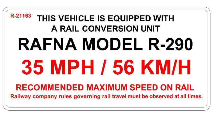
2 INSTALLATION OF STEERING WHEEL LOCK Bulletin MIO-SXXXXX Rev A Steering Wheel Lock Kit Components Part Number Description Qty S Steering Wheel Lock 1 S Steering Wheel Lock Decal 1 R Speed Decal 1 1. Ensure the front wheels are pointing straight ahead and the steering wheel is centered before installation. 2. The steering wheel lock consists of one steering wheel lock patch with Rafna logo and three adhesive back strips. 3. Without removing the protective backing, position one adhesive back strip on top of the steering column cover and another on the steering wheel. The strips should be close enough together so that the patch will cover both of them when the steering wheel lock is engaged. Ensure that the adhesive back strips do not interfere with any devices, such as the hazard light button on the steering column cover or the air bag cover on the steering wheel. Modify the adhesive back strips as required to clear any obstructions. Mark their locations on the steering column cover and the steering wheel. 4. Without removing the protective backing, position the third adhesive back strip in a convenient location on the dash (so that it does not interfere with the view and/or operation of the vehicle). This adhesive back strip will serve as a holder when the steering wheel lock is disengaged. Mark the location. 5. Scuff the three areas previously marked with medium / fine sand paper. The areas should be free of dust, dirt, and any oily residue. Thoroughly clean the areas with denatured alcohol or a similar non-oil based degreaser that will not react with the plastic. Let dry. 6. Take care when placing the adhesive back strips; once they are applied, they should not be removed. Do not touch the adhesive with your fingers. Removing the adhesive back strips once installed, or touching the adhesive may cause poor adhesion. 7. Peel off the protective backing from the adhesive back strips. Firmly press them into place as previously located. Do not disturb the adhesive back strips for 24 to 30 hours to allow the adhesive to fully cure. 8. Store the steering wheel lock patch on the adhesive back strip located on the dash. 9. Stick the steering wheel lock decal in a highly visible spot on the dashboard. 10. Stick the maximum speed decal in a highly visible spot, within clear sight of the operator, on the dashboard. -2-
3 -3-
4 -4-
5 OPERATION AND SERVICE OF STEERING WHEEL LOCK SAFETY PRECAUTIONS If any operating, services or parts problems are encountered, please call G&B Specialties, Inc. for technical assistance.! Failure to heed to any of the following warnings could result in severe bodily injury and/or equipment damage. Read and understand this manual completely before attempting operation of the railgear equipped vehicle. Operating instructions provided below only address the RAFNA railgear equipment. Applicable railway company procedures and policies must be adhered to. Railway company rules governing rail travel must be observed at all times. At level rail crossings, ensure that no other vehicles are approaching and flag the crossing to ensure safety. This vehicle will not operate crossing signals. Use caution when approaching and traversing level crossings. The steering wheel lock must be engaged at all times while on rail. -5-
6 OPERATION OF STEERING WHEEL LOCK Bulletin MIO-SXXXXX Rev A The following procedure details the steering wheel lock operation. 1. Placing The Vehicle On The Track: a) Engage the steering wheel lock after both the front and rear railgear are fully deployed and prior to rail travel. b) Turn the steering wheel until the front tires point straight ahead. c) Position the patch portion of the steering wheel lock onto the adhesive back strips affixed to the steering wheel and steering column cover. Press firmly into place. When installed on the adhesive back strips the patch should restrict the steering wheel from turning. 2. Traveling On Rail: a) The steering wheel lock must be engaged at all times while on rail. 3. Removing The Vehicle From The Track: a) Disengage the steering wheel lock after both the front and rear Railgear are fully retracted in the road position and prior to road travel. b) Firmly grasp the steering wheel lock patch s d-ring and peel it off the adhesive back strips. c) Store the patch on the adhesive back strip which serves as the holder located on the dash. SERVICE OF STEERING WHEEL LOCK Take care when removing the Patch. Due to certain plasticizers in the steering wheel steering column cover and dash, along with the vehicle s operating environment, the adhesive back strips may peel off and be removed. If the adhesive back strips do peel off, replace the strips with new ones at the earliest convenience. -6-
INSTALLATION OF TIRE PRESSURE MONITORING SENSOR 2017 FORD F-250/350
 SAFETY PRECAUTIONS INSTALLATION OF TIRE PRESSURE MONITORING SENSOR 2017 FORD F-250/350 BULLETIN MIO-R29FDTPS17 (REV B) If any installation problems are encountered, please call G&B Specialties for technical
INSTALLATION OF FRONT MOUNTING KIT 2017 FORD F-250/350 4X4
 INSTALLATION OF FRONT MOUNTING KIT 2017 FORD F-250/350 4X4 Bulletin MIO-R29FRXFXX17 Rev A SAFETY PRECAUTIONS If any installation problems are encountered, please call G&B Specialties for technical assistance
INSTALLATION OF FRONT MOUNTING KIT 2008 FORD F-250/350 4X4
 INSTALLATION OF FRONT MOUNTING KIT 2008 FORD F-250/350 4X4 Bulletin MIO-R29FRXF4X01 Rev B SAFETY PRECAUTIONS If any installation problems are encountered, please call G&B Specialties for technical assistance
INSTALLATION OF ROAD WHEELS AND TIRES 2008 Ford F-250/F-350 4x2
 INSTALLATION OF ROAD WHEELS AND TIRES 2008 Ford F-250/F-350 4x2 SAFETY PRECAUTIONS If any installation problems are encountered, please call G&B Specialties Inc. for technical assistance before continuing
INSTALLATION OF FRONT MOUNTING KIT 2008 FORD F-250/350 4X4 DIESEL (ONLY)
") SAFETY PRECAUTIONS INSTALLATION OF FRONT MOUNTING KIT 2008 FORD F-250/350 4X4 DIESEL (ONLY) Bulletin MIO-R29FRXF4X02 Rev B If any installation problems are encountered, please call G&B Specialties for
SAFETY PRECAUTIONS INSTALLATION OF FRONT MOUNTING KIT 2008 FORD F-250/350 4X4 DIESEL (ONLY) Bulletin MIO-R29FRXF4X02 Rev B If any installation problems are encountered, please call G&B Specialties for
INSTALLATION SAFETY PRECAUTIONS OF ROAD WHEELS AND TIRES
 INSTALLATION OF ROAD WHEELS AND TIRES SAFETY PRECAUTIONS If any installation problems are encountered, please call G&B Specialties, Inc. for technical assistance before continuing with the installation
INSTALLATION. Read and understand this manual completely before attempting installation of the equipment.
 SAFETY PRECAUTIONS INSTALLATION OF TIRE PRESSURE MONITORING SENSOR 2017 CHEVY 2500/3500 CK PICKUP Bulletin MIO-R29GMTPS17 (Rev B) If any installation problems are encountered, please call G&B Specialties
INSTALLATION OF ROAD WHEELS AND TIRES
 INSTALLATION OF ROAD WHEELS AND TIRES SAFETY PRECAUTIONS If any installation problems are encountered, please call G&B Specialties, Inc. for technical assistance before continuing with the installation
INSTALLATION OF FRONT MOUNTING KIT
 INSTALLATION OF FRONT MOUNTING KIT SAFETY PRECAUTIONS If any installation problems are encountered, please call G&B Specialties, Inc. for technical assistance before continuing with the installation process.!
INSTALLATION OF RAILGEAR KIT R-290HD REAR
 INSTALLATION OF RAILGEAR KIT R-290HD REAR Page 1 of 29 SAFETY PRECAUTIONS If any installation problems are encountered, please call G&B Specialties, Inc. for technical assistance before continuing with
Installation of Hydraulic Kit STD Controls w/ standard pump/manifold location
 BULLETIN MIO-H29RRG048B00 REV A Installation of Hydraulic Kit STD Controls w/ standard pump/manifold location SAFETY PRECAUTIONS If any installation problems are encountered, please call G&B Specialties
INSTALLATION. Read and understand this manual completely before attempting installation of the equipment.
 INSTALLATION OF TIRE PRESSURE MONITORING SENSOR 2007 AND UP, 2500 CHEVY SUBURBAN/YUKON & 2500/3500 CK PICKUP SAFETY PRECAUTIONS If any installation problems are encountered, please call G&B Specialties
Failure to heed to any of the following warnings could result in severe bodily injury and/or equipment damage.
 INSTALLATION OF HYDRAULIC KIT Page of Bulletin MIH9RRFR08B (Rev 0) SAFETY PRECAUTIONS If any installation problems are encountered, please call G&B Specialties, Inc. for technical assistance before continuing
Failure to heed to any of the following warnings could result in severe bodily injury and/or equipment damage.
 INSTALLATION OF HYDRAULIC KIT Page of Bulletin MIH9RRGX080 (Rev 0) SAFETY PRECAUTIONS If any installation problems are encountered, please call G&B Specialties, Inc. for technical assistance before continuing
OPERATION, SERVICE AND PARTS
 SAFETY PRECAUTIONS OPERATION, SERVICE AND PARTS OF HYDRAULIC KIT Page of Bulletin MOH9RRF08BX (Rev B) If any operating, service or parts problems are encountered, please call G&B Specialties, Inc. for
INSTALLATION OF REAR MOUNTING KIT 2017 FORD F-250/350 4X2/4X4 WITH OEM TOW HITCH
 INSTALLATION OF REAR MOUNTING KIT 2017 FORD F-250/350 4X2/4X4 WITH OEM TOW HITCH SAFETY PRECAUTIONS If any installation problems are encountered, please call G&B Specialties for technical assistance before
GENUINE Interior Lighting Kit
 GENUINE Interior Lighting Kit INSTALLATION INSTRUCTIONS Thank you for purchasing a genuine Mazda accessory. Before removal and installation, be sure to thoroughly read these instructions. Please read the
GENUINE Interior Lighting Kit
 GENUINE Interior Lighting Kit INSTALLATION INSTRUCTIONS Thank you for purchasing a genuine Mazda accessory. Before removal and installation, be sure to thoroughly read these instructions. Please read the
Wheel Arch Trim Set. Installation Manual. This section covers installation of the wheel arch trim set.
 Wheel Arch Trim Set FORESTER Wheel Arch Trim Set EN PART # E20SSG000 This section covers installation of the wheel arch trim set. Installation Manual Note: Before performing installation, be sure to read
Remote engine start INSTALLATION INSTRUCTIONS
 GENUINE Remote engine start INSTALLATION INSTRUCTIONS Thank you for purchasing a genuine Mazda accessory. Before removal and installation, be sure to thoroughly read these instructions. Please read the
Remote engine start INSTALLATION INSTRUCTIONS
 GENUINE Remote engine start INSTALLATION INSTRUCTIONS Thank you for purchasing a genuine Mazda accessory. efore removal and installation, be sure to thoroughly read these instructions. Please read the
Vehicle and all installation material temperatures must be within the following range before and during installation: 60 F [15 C] and 100 F [43 C].
![Vehicle and all installation material temperatures must be within the following range before and during installation: 60 F [15 C] and 100 F [43 C].](/thumbs/90/101815149.jpg "Vehicle and all installation material temperatures must be within the following range before and during installation: 60 F [15 C] and 100 F [43 C].") INSTALLATION INSTRUCTIONS DESCRIPTION: BODY SIDE MOLDING KIT, DEALER Vehicle and all installation material temperatures must be within the following range before and during installation: 60 F [15 C] and
INSTALLATION INSTRUCTIONS DESCRIPTION: BODY SIDE MOLDING KIT, DEALER Vehicle and all installation material temperatures must be within the following range before and during installation: 60 F [15 C] and
CERTAIN 2005 MODEL YEAR FIVE HUNDRED, MONTEGO AND CERTAIN 2005 AND 2006 MODEL YEAR FREESTYLE VEHICLES DOOR LATCH WATER PROTECTION
 CERTAIN 2005 MODEL YEAR FIVE HUNDRED, MONTEGO AND CERTAIN 2005 AND 2006 MODEL YEAR FREESTYLE VEHICLES LATCH WATER PROTECTION ATTACHMENT III PAGE 1 OF 9 OVERVIEW Depending on vehicle and build date, this
Pub Mounting Instructions For Automotive GPS Receivers
 Pub. 988-0154-631 Mounting Instructions For Automotive GPS Receivers This instruction sheet describes how to assemble and use the quickrelease flexible suction cup mount for Lowrance automotive GPS receivers.
PowerLevel s e r i e s
 Owner s Manual Hydraulic Leveling CONTENTS Introduction Operation Control Panel Automatic Leveling Manual Leveling Retracting Jacks Remote Operation Care & Maintenance Troubleshooting Error Codes 1 2 2
QLD & SA CONTENTS. MANH-007 Rev. E Hazard System Customer Service Team Page 1 of (Australia only) (International)
 (International)") QLD & SA CONTENTS 1 PLACING LAMPS AND SIGNS ON YOUR BUS 2 INSTALLING THE LAMPS AND SIGN 2.1 School bus warning sign 2.2 Surface Mount Lamp (823-003A or 823-004A) 2.3 Window Mount Lamp (823-005A or 823-006A)
QLD & SA CONTENTS 1 PLACING LAMPS AND SIGNS ON YOUR BUS 2 INSTALLING THE LAMPS AND SIGN 2.1 School bus warning sign 2.2 Surface Mount Lamp (823-003A or 823-004A) 2.3 Window Mount Lamp (823-005A or 823-006A)
Vehicle Rear Observation System With Integrated Parking Sensors
 Vehicle Rear Observation System With Integrated Parking Sensors Model: CAMSBAR Installation/User Manual Features: 2.5" LCD Color Display 2 Ultra Sonic Rear Obstacle Sensors On-screen Display Function Automatically
6722 Rev. A CAPACITY: 22 TON TRUCK AXLE JACK WITH AIR RETURN
 CONTENTS: Page Specifications 2 Warning Information Setup Instructions and Operating Instructions 4 Preventative Maintenance, Inspection and Proper Storage 5 Troubleshooting, Owner/User Responsibility
GENUINE PARKING SENSORS (Rear)
") GENUINE PARKING SENSORS (Rear) INSTALLATION INSTRUCTIONS Thank you for purchasing a genuine Mazda accessory. Before removal and installation, be sure to thoroughly read these instructions. Please read
GENUINE PARKING SENSORS (Rear) INSTALLATION INSTRUCTIONS Thank you for purchasing a genuine Mazda accessory. Before removal and installation, be sure to thoroughly read these instructions. Please read
GENUINE REAR SPOILER
 GENUINE REAR SPOILER IMPORTANT POINTS IN PAINTING PART NAME: REAR SPOILER PART NUMBER: 0000-8Y-H50/GHK1 V4 920/G44B V4 920 VEHICLE: MAZDA6 1 PAINT AREAS SURFACE TREATMENT a : Paint same as body color b
OUT FRONT ELECTRIC HYDRAULIC (W/E-47H) FOR STRAIGHT TRIPEDGE PLOWS (PULL AWAY MOUNTINGS)
 FOR STRAIGHT TRIPEDGE PLOWS (PULL AWAY MOUNTINGS)") 80052 March 6, 1995 OUT FRONT ELECTRIC HYDRAULIC (W/E-47H) FOR STRAIGHT TRIPEDGE PLOWS (PULL AWAY MOUNTINGS) ITEM STOCK DESCRIPTION QTY. 51 15759 LIFT UNIT (E-47H) 1 52 817000 020 10" CYLINDER 2 53 15370
80052 March 6, 1995 OUT FRONT ELECTRIC HYDRAULIC (W/E-47H) FOR STRAIGHT TRIPEDGE PLOWS (PULL AWAY MOUNTINGS) ITEM STOCK DESCRIPTION QTY. 51 15759 LIFT UNIT (E-47H) 1 52 817000 020 10" CYLINDER 2 53 15370
Mazda North American Operations Irvine, CA
 Service Bulletin Mazda North American Operations Irvine, CA 92618-2922 Subject: CRACK APPEARS IN CENTER OF DASHBOARD Bulletin No: 09-070/09 2004-2009 MAZDA3 - CRACK APPEARS IN CENTER OF DASHBOARD APPLICABLE
VIC CONTENTS. MANH-021 Rev. C Hazard Systems Customer Service Team Page 1 of (Australia only) (International)
 (International)") VIC CONTENTS 1. PLACING LAMPS AND SIGNS ON YOUR BUS 2. INSTALLING THE LAMPS AND SIGN 2.1. School bus warning sign 2.2. Surface Mount Lamp (823-003A or 823-004A) 2.3. Window Mount Lamp (823-005A or 823-006A)
VIC CONTENTS 1. PLACING LAMPS AND SIGNS ON YOUR BUS 2. INSTALLING THE LAMPS AND SIGN 2.1. School bus warning sign 2.2. Surface Mount Lamp (823-003A or 823-004A) 2.3. Window Mount Lamp (823-005A or 823-006A)
1000-LB. MOTORCYCLE LIFT TABLE OWNER S MANUAL
 1000-LB. MOTORCYCLE LIFT TABLE OWNER S MANUAL WARNING: Read carefully and understand all ASSEMBLY AND OPERATION INSTRUCTIONS before operating. Failure to follow the safety rules and other basic safety
Please pay attention to all Cautions and Notes within these instructions.
 Mustang Cluster Kit - INSTALLATION INSTRUCTIONS - For use with Ford Mustang (1994-1998) and Simco Kit Part # s 2034-7XX Revised: Dec 30, 2008 Rev. C Please read and understand all instructions before attempting
GENUINE MUD FLAP (FRONT)
") GENUINE MUD FLAP (FRONT) INSTALLATION AND USER S INSTRUCTIONS Thank you for purchasing a Genuine Mazda Accessory. Before removal and installation, be sure to thoroughly read these instructions. Please
GENUINE MUD FLAP (FRONT) INSTALLATION AND USER S INSTRUCTIONS Thank you for purchasing a Genuine Mazda Accessory. Before removal and installation, be sure to thoroughly read these instructions. Please
LightRider. Instructions for Power Link Helmet Light. Helmet Vertical Midline
 LightRider Instructions for Power Link Helmet Light Helmet Vertical Midline Look at the back of your helmet. Then imagine a vertical line that runs up the back and divides your helmet into right and left
Service Bulletin No. 3063
 Service Bulletin No. 3063 MODEL TYPE SECTION/GROUP DATE J4500 Series Coaches Service Information 3--Body Aug. 03, 2011 SUBJECT CONDITIONS FENDER PANEL STUD ASSEMBLY Parts may be purchased from MCI Service
2-light Warm/Cool White LED Strips Usage
 2-light Warm/Cool White LED Strips Usage Guide This Guide describes how to use the 2-light Warm or Cool White LED Strips from Brickstuff. Written By: Rob K 2017 brickstuff.dozuki.com Page 1 of 8 PARTS:
PART #31675/31675P/31675PM
 PART #31675/31675P/31675PM Exhaust, Cat-Back, Trailblazer SS, 2006-2007 PACKING LIST Before installation, use this check list to make sure all necessary parts have been included. ITEM QTY CHECK PART NUMBER
GENUINE FOG LIGHT INSTALLATION AND USER S INSTRUCTIONS
 GENUINE FOG LIGHT INSTALLATION AND USER S INSTRUCTIONS Thank you for purchasing a genuine Mazda accessory. Before removal and installation, be sure to thoroughly read these instructions. Please read the
CAUTION. Start & Stop Procedures. Section 1-2. Engine Oil Level
 Section 1-2 Start & Stop Procedures Before operating this machine, the operator must have: received operator training, a familiarity with this manual, and a complete understanding of all the procedures
2,000 Lbs Heavy-Duty Engine Stand
 ITEM#: TR29005 2,000 Lbs Heavy-Duty Engine Stand WARNING: Read carefully and understand all ASSEMBLY AND OPERATION INSTRUCTIONS before operating. Failure to follow the safety rules and other basic safety
Bolt-On/Rugged Fender Flares Nissan Titan (04-15) Please read instructions entirely before installing this product.
 Please read instructions entirely before installing this product.") Please read instructions entirely before installing this product. Hardware Included QTY FUEL DOOR CLIP 1 Bolt Kit Included QTY ALCOHOL TOWELETTE 4 M4 SCREW 1 ALLEN KEY BOLT 42 CLIP.9MM 2 ABRASIVE RESISTANT
Please read instructions entirely before installing this product. Hardware Included QTY FUEL DOOR CLIP 1 Bolt Kit Included QTY ALCOHOL TOWELETTE 4 M4 SCREW 1 ALLEN KEY BOLT 42 CLIP.9MM 2 ABRASIVE RESISTANT
Soap/Sanitizer Dispensers
 Soap/Sanitizer Dispensers Installation & Operating Instruction Manual Thoroughly read this instruction booklet before operating Sloan dispensers. Keep this Installation & Operating Instruction Manual with
Owner smanual. Banks Ram-Air Intake System Chevrolet 6.6L (LML) Duramax Turbo-Diesel Pickups. with Installation Instructions
 Duramax Turbo-Diesel Pickups. with Installation Instructions") with Installation Instructions Owner smanual Banks Ram-Air Intake System 2013-2014 Chevrolet 6.6L (LML) Duramax Turbo-Diesel Pickups THIS MANUAL IS FOR USE WITH KIT 42230 & 42230-D Gale Banks Engineering
with Installation Instructions Owner smanual Banks Ram-Air Intake System 2013-2014 Chevrolet 6.6L (LML) Duramax Turbo-Diesel Pickups THIS MANUAL IS FOR USE WITH KIT 42230 & 42230-D Gale Banks Engineering
Swing Back Trailer Jack
 Swing Back Trailer Jack Model: 91474 ASSEMBLY AND OPERATING INSTRUCTIONS Diagrams within this manual may not be drawn proportionally. Due to continuing improvements, actual product may differ slightly
MiTek Machinery Division. Service Bulletin
 MiTek Machinery Division Service Bulletin Machinery Affected: Document: Title: Applies To: Distribution: RoofGlider Press SB198 Redesigned Push Bar Push Bars Manufactured With Gas Spring and Clamp-Style
TOYOTA PRIUS CONSOLE APPLIQUES Preparation
 Preparation Part Number: PT948-47160-02 Kit Contents Item # Quantity Reqd. Description 1 1 Console Applique 2 1 Front Face Cover Applique 3 Hardware Bag Contents Item # Quantity Reqd. Description 1 2 3
Bolt-On/Rugged Fender Flares Dodge Ram 1500/2500/3500 (09-12) Please read instructions entirely before installing this product.
 Please read instructions entirely before installing this product.") Please read instructions entirely before installing this product. Hardware Included QTY Hardware Included QTY Bolt Kit Included QTY EXTRUSION 29.0ft ALCOHOL TOWELETTE 4 ALLEN KEY BOLT 42 NUT 42 Ensure
Please read instructions entirely before installing this product. Hardware Included QTY Hardware Included QTY Bolt Kit Included QTY EXTRUSION 29.0ft ALCOHOL TOWELETTE 4 ALLEN KEY BOLT 42 NUT 42 Ensure
SUPERLIFT Level-It for 2015 GM COLORADO / CANYON INSTALLATION INSTRUCTIONS
 FORM#40028.01-070115 PRINTED IN U.S.A. PAGE 1 OF 6 SUPERLIFT Level-It for 2015 GM COLORADO / CANYON INSTALLATION INSTRUCTIONS INTRODUCTION Installation requires a professional mechanic. The overall vehicle
Be sure to carry out the following before starting work
 Be sure to carry out the following before starting work If an older version of the CMU software is being used, the CarPlay/Android Auto-compatible USB hub may not be recognized. If the software version
PRODUCT INSTALLATION GUIDE
 PRODUCT INSTALLATION GUIDE MODEL: PRODUCT CODE: PRODUCT DESCRIPTION: 4COMM 4COMMSFK CouplerTec Commercial Heavy Duty Electronic Rustproofing System 12V / 24V Four Capacitive Couplers KIT CONTENTS: ITEM
Owner smanual. Banks Ram-Air Intake System Chevrolet 6.6L (LML) Duramax Turbo-Diesel Pickups. with Installation Instructions
 Duramax Turbo-Diesel Pickups. with Installation Instructions") with Installation Instructions Owner smanual Banks Ram-Air Intake System 2015 Chevrolet 6.6L (LML) Duramax Turbo-Diesel Pickups THIS MANUAL IS FOR USE WITH KIT 42250 & 42250-D Gale Banks Engineering 546
with Installation Instructions Owner smanual Banks Ram-Air Intake System 2015 Chevrolet 6.6L (LML) Duramax Turbo-Diesel Pickups THIS MANUAL IS FOR USE WITH KIT 42250 & 42250-D Gale Banks Engineering 546
ASSEMBLY and OPERATING INSTRUCTIONS Mission Oaks Blvd. / Camarillo, CA 93011
 SPARK PLUG CLEANER ASSEMBLY and OPERATING INSTRUCTIONS 3491 Mission Oaks Blvd. / Camarillo, CA 93011 Copyright 1997 by Harbor Freight Tools. All rights reserved. No portion of this manual or any artwork
Dear Customers. : i MiEV INSTRUMENT PANEL ILLUMINATION INSTALLATION AND HANDLING INSTRUCTIONS. Attention
 Dear Customers Thank you for purchasing a Mitsubishi genuine optional part. For proper use of the product, please read this leaflet thoroughly. It is recommended you keep this leaflet at hand for future
TXJ0500/RR500 1,000-lbs. Truck Bed Roller Dolly
 OWNER S MANUAL TXJ0500/RR500 1,000-lbs. Truck Bed Roller Dolly WARNING: Questions, problems, missing parts? Before returning to your retailer, call our customer service department at 1-888-448-6746, 8
SYMPTOM/CONDITION: The Service 4WD lamp is illuminated even though the truck is not a 4X4 vehicle.
 NUMBER: GROUP: 08-032-00 REV. A Electrical DATE: Dec. 29, 2000 This bulletin is supplied as technical information only and is not an authorization for repair. No part of this publication may be reproduced,
DM-135 DRUM MOWER USER S MANUAL
 DM-135 DRUM MOWER USER S MANUAL 1 DM135 DRUM MOWER INSTRUCTIONS CHAPTER 1 SAFE OPERATION Do not attempt to operate the mower until you have read the operator s manual and all the safety signs on the mower.
INSTALLATION INSTRUCTIONS
 INSTALLATION INSTRUCTIONS Accessory Application Publications No. 3RD ROW P/N 08R12-SHJ-100 2006 ODYSSEY AII 30563-31117 Issue Date OCT 2005 PARTS LIST Left side rear sunshade Driver s Side 1. Remove the
GENUINE REAR SPOILER
 GENUINE REAR SPOILER INSTALLATION INSTRUCTIONS Thank you for purchasing a genuine Mazda accessory. Before removal and installation, be sure to thoroughly read these instructions. Please read the contents
INSTALLATION INSTRUCTIONS
 TM WEIGHTLIFTER Tailgates By THIEMAN TWL 125, 16, 20 INSTALLATION INSTRUCTIONS! IMPORTANT! KEEP IN VEHICLE! PLEASE READ AND UNDERSTAND THE CONTENTS OF THIS MANUAL BEFORE OPERATING THE EQUIPMENT. NTEA T
STEERING COLUMN - STANDARD
 STEERING COLUMN - STANDARD 1994 Toyota Celica 1994 STEERING Toyota - Steering Column - Standard Celica DESCRIPTION & OPERATION Steering column is a collapsible 2-piece design. Columns use shear pins to
PRODUCT INSTALLATION GUIDE
 PRODUCT INSTALLATION GUIDE PRODUCT CODE: PRODUCT DESCRIPTION: 4WDXHDSFK 4WD EXTREME HEAVY DUTY 6 COUPLER SYSTEM SELF FIT KIT KIT CONTENTS: QTY PRODUCT QTY PRODUCT QTY PRODUCT 1 Couplertec Module 3 Black
RoadRelay 4. Installation Guide
 RoadRelay 4 Installation Guide RoadRelay 4 Installation Guide Bulletin No. 3401767 Revision B Copyright 2002, Cummins Inc. All rights reserved. Cummins Inc. shall not be liable for technical or editorial
1000-LB. ENGINE STAND
 1000-LB. ENGINE STAND WARNING: Read carefully and understand all ASSEMBLY AND OPERATION INSTRUCTIONS before operating. Failure to follow the safety rules and other basic safety precautions may result in
Backhoe for Compact Utility Loaders
 Form No. 54-4 Rev A Backhoe for Compact Utility Loaders Model No. 6 6000000 and Up Operator s Manual Register your product at www.toro.com. Original Instructions (EN) Contents Page Introduction.................................
6602LP CAPACITY: 2 TON LOW RIDER SERVICE JACK
 CONTENTS: Page 1 Specifications 2 Warning Information 3 Setup Instructions 4 Operating Instructions, Preventative Maintenance, Inspection and Proper Storage 5 Hydraulic Jack Maintenance Guide and Regular
Motion System Components Diagram. Note: #2 Mirror Cover and X-Axis Motor Cover have been removed for visibility. Maintenance.
 Professional Laser System PLS3.75, PLS4.75, PLS6.75 and PLS6.150D Keeping the laser system clean will ensure the highest quality engraving. A clean laser system is the best performing laser system. The
Ground Effects, P/N: (V6), (V8)
, (V8)") , P/N: 92248596 (V6), 92248560 (V8) 3. Open trunk and remove 3 scrivets per side. Retain. Remove LH and RH tail lamp access cover. Retain. Refer to Figure 1. NOTE: Installation is made easier with the
, P/N: 92248596 (V6), 92248560 (V8) 3. Open trunk and remove 3 scrivets per side. Retain. Remove LH and RH tail lamp access cover. Retain. Refer to Figure 1. NOTE: Installation is made easier with the
Installation Instructions
 Preparing your vehicle to install your brake system upgrade 1. Rack the vehicle. 2. If you don t have a rack, then you must take extra safety precautions. 3. Choose a firmly packed and level ground to
GENUINE PARTS INSTALLATION INSTRUCTIONS
 GENUINE PRTS INSTLLTION INSTRUCTIONS DESCRIPTION: PPLICTION: PRT NUMBER: KIT CONTENTS: Side Window Deflector Quest (2011) H0800 1J00 Item Qty. 1 B 1 C 1 D 1 E 4 F 4 G 1 Part Description Side Window Deflector
RAV4 TNS310 (Traffic) Plus
 Plus") TNS310 (Traffic) Plus RHD installation instructions Model year: 005 Vehicle code: **A3***-*****W Part number TNS310 Plus: Sub wire harness No 1: 08673-64801 Sub wire harness No : 08673-64800 Part number
TNS310 (Traffic) Plus RHD installation instructions Model year: 005 Vehicle code: **A3***-*****W Part number TNS310 Plus: Sub wire harness No 1: 08673-64801 Sub wire harness No : 08673-64800 Part number
8-TON LONG RAM DOUBLE PISTON JACK OWNER S MANUAL
 8-TON LONG RAM DOUBLE PISTON JACK OWNER S MANUAL WARNING: Read carefully and understand all ASSEMBLY AND OPERATION INSTRUCTIONS before operating. Failure to follow the safety rules and other basic safety
P Original Series Cargo Van Lift Mounting Instructions Fullsize Ford Van present. Preparing the Gate
 Fullsize Ford Van- 1992-present Preparing the Gate 1. Remove the mounting hardware which is banded to the liftgate. 2. Verify mounting kit (Figure 1 and Table 1). S-400-40 STRAP VAN MOUNTING EAR BENT BRACKET
Owner smanual. Banks Ram-Air Intake System Chevrolet 6.6L Duramax Turbo-Diesel Pickups. with Installation Instructions
 Owner smanual with Installation Instructions Banks Ram-Air Intake System 2001-2005 Chevrolet 6.6L Duramax Turbo-Diesel Pickups THIS MANUAL IS FOR USE WITH KITS 42132, 42135, 42132-D, 42135-D Gale Banks
2.5 TON TROLLEY JACK WITH 360 HANDLE OWNER S MANUAL
 2.5 TON TROLLEY JACK WITH 360 HANDLE OWNER S MANUAL WARNING: Read carefully and understand all ASSEMBLY AND OPERATION INSTRUCTIONS before operating. Failure to follow the safety rules and other basic safety
INSTALLATION MANUAL. Power-Pole Blade Edition Shallow Water Anchor. Installation Instructions
 INSTALLATION MANUAL Power-Pole Blade Edition Shallow Water Anchor Installation Instructions CAUTION: Read this instruction manual carefully. Become familiar with the controls and know how to operate the
2005 Cadillac CTS BRAKES Disc Brakes - CTS
 Removal Procedure 1. Inspect the fluid level in the brake master cylinder reservoir. 2. If the brake fluid level is midway between the maximum-full point and the minimum allowable level, no brake fluid
Owner smanual. Banks Ram-Air Intake System Ford Power Stroke 6.7L Turbo Diesel F250/F350/F450 Trucks. with Installation Instructions
 Owner smanual with Installation Instructions Banks Ram-Air Intake System 2011-2015 Ford Power Stroke 6.7L Turbo Diesel F250/F350/F450 Trucks THIS MANUAL IS FOR USE WITH SYSTEM 42215 & 42215-D Gale Banks
ABSOLUTE EQUIPMENT PTY LTD
 Manual Hydraulic Toe Jack Model DTJ Series ABSOLUTE EQUIPMENT PTY LTD 2/186 Granite Street, GEEBUNG QLD 4034 Australia sales@absoluteequipment.com.au Phone: +61 7 3865 4006 Fax: +61 7 3102 6288 This is
Accessory Harness & Bracket Kit
 Accessory Harness & Bracket Kit Stainless Steel Hopper Spreader Gas 9969 June 5, 06 Lit. No. 98986, Rev. 0 PARTS LIST 9 4 8 7 6 4 3 8 VIB LIGHT STROBE PREWET 5 0 4 9969 Accessory Harness & Bracket Kit
2005 Cadillac CTS BRAKES Disc Brakes - CTS
 Removal Procedure 1. Inspect the fluid level in the brake master cylinder reservoir. 2. If the brake fluid level is midway between the maximum-full point and the minimum allowable level, no brake fluid
GENUINE ILLUMINATED SCUFF PLATE
 GENUINE ILLUMINATED SCUFF PLATE INSTALLATION AND USER S INSTRUCTIONS Thank you for purchasing a Genuine Mazda Accessory. Before removal and installation, please thoroughly read these instructions. For
Soap/Sanitizer Dispensers
 Soap/Sanitizer Dispensers Installation & Operating Instruction Manual Thoroughly read this instruction booklet before operating Sloan dispensers. Keep this Installation & Operating Instruction Manual with
Instruction Sheet. Follower Bar. Compression Roller Assembly (Roller Ass'y/Cylinder Clevis/ Roller Ass'y)
") Gardner Bender Instruction Sheet Model B400, B400D, B400L & B400DL Eegor TM Hydraulic Benders IMPORTANT RECEIVING INSTRUCTIONS: Visually inspect all components for shipping damage. If any shipping damage
Gardner Bender Instruction Sheet Model B400, B400D, B400L & B400DL Eegor TM Hydraulic Benders IMPORTANT RECEIVING INSTRUCTIONS: Visually inspect all components for shipping damage. If any shipping damage
Table of Contents General Information Safety Message Classifi cation...2 Safety Notes...3 Terminology...4 Coupler Lifting Lug...
 Table of Contents General Information Safety Message Classifi cation...2 Safety Notes...3 Terminology...4 Coupler Lifting Lug...6 Assembly and Installation General Information...7 How it works...7 Component
ABSOLUTE EQUIPMENT PTY LTD
 Manual Hydraulic Toe Jack Model DTJ Series ABSOLUTE EQUIPMENT PTY LTD 2/186 Granite Street, GEEBUNG QLD 4034 Australia sales@absoluteequipment.com.au Phone: +61 7 3865 4006 Fax: +61 7 3102 6288 This is
JEEP WRANGLER, RUBICON, UNLIMITED (TJ & TJL) 1 BODY LIFT KIT INSTALLATION INSTRUCTIONS KIT# 951
 1 BODY LIFT KIT INSTALLATION INSTRUCTIONS KIT# 951") 3651 N Highway 89 Chino Valley, AZ 86323 (928) 636-7080 www.p-a-g.net JEEP WRANGLER, RUBICON, UNLIMITED (TJ & TJL) 1 BODY LIFT KIT INSTALLATION INSTRUCTIONS 1997-2006 KIT# 951 Installation of a Performance
3651 N Highway 89 Chino Valley, AZ 86323 (928) 636-7080 www.p-a-g.net JEEP WRANGLER, RUBICON, UNLIMITED (TJ & TJL) 1 BODY LIFT KIT INSTALLATION INSTRUCTIONS 1997-2006 KIT# 951 Installation of a Performance
Installation, Operation & Maintenance Manual for Flo-Max II Coupler Model FM126
 IMPORTANT: The Flo-Max II coupler is designed to disconnect the nurse tank hose from a tool bar before the straight pull force on the hose exceeds 450 pounds. Upon disconnect, swing checks in both halves
Brake Shoe: Service and Repair Removal Procedure
 2000 Buick Century V6-3.1L VIN J Copyright 2013, ALLDATA 10.52 Page 1 Brake Shoe: Service and Repair Removal Procedure ^ Tools Required - J38400 Brake Shoe Spanner and Spring Remover Caution: Keep fingers
Owner smanual. Banks Ram-Air Intake System Ford Power Stroke 7.3L Turbo-Diesel F250/F350/F450 Trucks. with Installation Instructions
 with Installation Instructions Owner smanual Banks Ram-Air Intake System 1999-2003 Ford Power Stroke 7.3L Turbo-Diesel F250/F350/F450 Trucks THIS MANUAL IS FOR USE WITH SYSTEM 42210 & 42210-D Gale Banks
Hydraulic Wheel Dolly
 Hydraulic Wheel Dolly Operating Instructions & Parts Manual Model Number HW93766 Capacity 3/4 Ton Made in the U.S.A. This is the safety alert symbol. It is used to alert you to potential personal injury
Engineered to Ride, Built to last
 Congratulations on your selection to purchase an Arnott Air Suspension System. We at Arnott Air Suspension Systems are proud to offer a high quality product at the industries most competitive pricing.
Instruction Manual. Maximum Operating Pressure 700 bar
 Remote Hydraulic Cutter Model HC-120R Maximum Operating Pressure 700 bar ABSOLUTE EQUIPMENT PTY LTD 2/186 Granite Street, GEEBUNG QLD 4034 Australia sales@absoluteequipment.com.au Phone: +61 7 3865 4006
FORD BRONCO BODY LIFT KIT INSTALLATION INSTRUCTIONS KIT # KIT #843
 FORD BRONCO BODY LIFT KIT INSTALLATION INSTRUCTIONS 1992-1996 2 KIT #842 1992-1996 3 KIT #843 This kit should only be installed on a vehicle that is in good working condition. Before you install the kit,
INSTALLATION OPERATING SERVICE AND SAFETY INSTRUCTIONS
 MODEL GE 970 Boom Mounted Compactor / Driver GENPAC INSTALLATION OPERATING SERVICE AND SAFETY INSTRUCTIONS PARTS LIST 1.0 INTRODUCTION The Genpac GE-970 is a boom-mounted hydraulic vibrating plate compactor
OVERVIEW: This bulletin involves removing and installing the deck lid spoiler.
 NUMBER: 23-041-05 GROUP: Body DATE: September 9, 2005 This bulletin is supplied as technical information only and is not an authorization for repair. No part of this publication may be reproduced, stored
2000 Ranger Workshop Manual
 SECTION 211-02: Power Steering 2000 Ranger Workshop Manual REMOVAL AND INSTALLATION Procedure revision date: 06/1/1999 Gear Torsion Bar Suspension Special Tool(s) Remover, Tie Rod End 211-001 (TOOL-3290-D)
INSTALLATION INSTRUCTIONS
 INSTALLATION INSTRUCTIONS Accessory Application Publications No. THIRD-ROW P/N 08R12-SHJ-100 2008 ODYSSEY AII 38141 Issue Date OCT 2007 PARTS LIST Left rear sunshade Driver s Side 1. Remove the spare tire