9000, 9100 AND 9500 VALVES
|
|
|
- Emery Peters
- 6 years ago
- Views:
Transcription


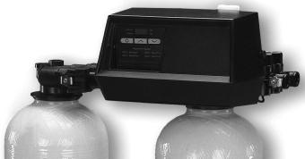
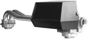
1 9000, 9100 AND 9500 VALVES
2 TABLE OF CONTENTS 1 VALVES SPECIFICATIONS P. 3 2 VALVE INSTALLATION P. 4 3 INSTALLATION INSTRUCTIONS P. 5 4 MECHANICAL TIMER P. 6 5 CYCLE TIME SETTINGS P. 7 6 CAPACITY SETTINGS P. 8 7 TIMER ASSEMBLIES P. 9 8 POWER HEAD 9000/9100/9500 P VALVE BODY 9000 P SECOND TANK ADAPTER 9000 P VALVE BODY 9100 P SECOND TANK ADAPTER 9100 P VALVE BODY 9500 P SECOND TANK ADAPTER 9500 P BRINE SYSTEMS 1600 & 1700 FOR 9500 P / 4 AND 1 METERS FOR 9000 & 9100 P / 2 METERS FOR 9500 P VALVES DIMENSIONS P TROUBLESHOOTING P. 26 2
3 1 - VALVE SPECIFICATIONS Installation N Valve serial N Tank size Resin type Resin volume System capacity Inlet water hardness Water hardness after mixing valve Brine tank size Quantity of salt per regeneration m 3 TH TH TH L Kg VALVE TECHNICAL CHARACTERISTICS VALVE TYPE 9000/ / /4 meter 1 meter 9500/ / /2 meter INITIATION Meter immediate SET REGENERATION m 3 or L REGENERATION CYCLE SETTINGS Cycle 1 Cycle 2 Cycle 3 Cycle 4 Min. Min. Min. Min. HYDRAULIC SETTINGS Injector size Pressure regulator Drain line flow control (DLFC) GPM 1,4 bar (20 PSI) 2,1 bar (30 PSI) Brine line flow control (BLFC) GPM Without VOLTAGE 24V/50Hz 24V/60Hz without transformer NOTES 3
4 2 - VALVE INSTALLATION Water Pressure A minimum of 1,4 bar of water pressure is required for the regeneration valve to operate effectively. Do not exceed 8,5 bar ; if you face this case, you should install a pressure regulator upstream the system. Electrical Connection An uninterrupted current supply is required. Please make sure that your voltage supply is compatible with your unit before installation. If the electrical cable is damaged, it must imperatively be replaced by a qualified personal. Existing Plumbing Existing plumbing should be in a good shape and free from limescale. In doubt, it is preferable to replace it. The installation of a pre filter is always advised. 2.4 By-pass Always provide a by pass valve for the installation, if the unit is not equipped with one. 2.5 Water Temperature Water temperature is not to exceed 43 C, and the unit cannot be subjected to freezing conditions. (It could cause irreversible damage to the valve). 2.6 Presentation Fast rinse Brine draw and slow rinse Backwash Brine refill Service Service vessel indicator 4
5 3 - INSTALLATION INSTRUCTIONS Install the softener pressure vessels in a chosen place on a flat firm surface. During cold weather, it is recommended to bring the valve back to room temperature before operating. All plumbing for water inlet, distribution and drain lines should be done correctly in accordance with legislation in force at the time of installation. The distribution tube should be cut flush with the top of the tank. Slightly bevel the ridge in order to avoid deterioration of the seal whilst fitting the valve. The tube for 9000/9100 is Ø27 mm (1 ) and DN40 for the 9500 valve. Lubricate the distribution tube joint and the joint with a 100% Silicon lubricant. Never use other types of greases that may damage the valve. All soldering on main plumbing and to the drain line should be done before fitting the valve. Failing to do so can generate irreversible damages. Use Teflon tape if necessary in order to seal between the drain fitting and the outlet flow control. Ensure that the floor under the brine tank is clean and flat. On units with by-pass, place in by-pass position. Turn on the main water supply. Open a cold soft water tap nearby and let run a few minutes or until the system is free from foreign material (usually solder) that may have resulted from the installation. Once clean, close the water tap. Place the by-pass in service position and let water flow into the mineral tank. When water flow stops, slowly open a cold water tap nearby and let run until the air is purged from the unit. Plug the valve to a power source. Once plugged the valve may do a cycle on its own in order to go to service position. The valve has an indicator informing the installer of its position: on the side of the motor that pilots the pistons, there is a sticker with images (see chap 2.6). Start a regeneration by turning the wheel on the timer (see p.6) to bring the valve in service on the 2 nd vessel and execute each cycle of the regeneration (see p.7) in order to empty residual air in the first vessel that has just filled up. Do the same action for the second vessel. Fill approximately 25mm of water above the grid plate, (if used). Otherwise, fill to the top of the air check in the brine tank. Do not add salt to the brine tank at this time. Initiate a manual regeneration, bring the valve into brine draw and slow rinse position in order to draw water from the brine tank until the blockage of the air-check valve; the water level will be approximately in the middle of the air check. Open the cold water tap and let water flow in order to drain the air out of the circuit. Put the valve in brine refill position and let it get back to service position automatically. Now you can add salt to the brine tank, the valve will operate automatically. 5

6 4 - MECHANICAL TIMER Capacity wheel. Remaining capacity indicator. Initiate the regeneration by turning the wheel clockwise. Meter cable connection. Timer motor - 1/30 RPM. - 1/15 RPM. Program wheel for cycle time regenerations. 2 microswitches: - Lower microswitch for the autohold of the motor and the service position of the timer. - Upper microswitch. It activates regeneration cycles. Programmation label (82 or 162 minutes) according to motor speed.: - 2 min. per pin with the 1/30RPM motor. - 1 min per pin with the 1/15 RPM motor. Spare pins. 6


 taking into account the following parameters: - The flow regulator in the brine tank expressed in gallon per minute (gpm) - The amount of salt needed to")
7 5 - CYCLE TIME SETTINGS DOWN FLOW UP FLOW 1 Backwash Fast rinse 2 Brine draw and slow rinse Brine draw and slow rinse (down flow) (upflow) 3 Fast rinse Backwash 4 Brine refill Brine refill 5 Always put these pins at the end of the setting Cycle times are factory preset. Each pin or hole is equivalent to 2 minutes. It is highly recommended to verify if each cycle time is adapted to specific site conditions. To modify the cycle time of each regeneration, add or remove pins. Example: view diagram on the right 1- Backwash : it goes from 10 to 14 minutes 2- Brine draw and slow rinse: it s reduced from 60 to 40 minutes 3- Fast rinse: it s reduced from 10 to 6 minutes 4- Brine refill : it s reduced from 20 to 12 minutes. The 9000/91000/9500 valve has a brine refill cycle. Time needs to be calculated (in minutes ) taking into account the following parameters: - The flow regulator in the brine tank expressed in gallon per minute (gpm) - The amount of salt needed to regenerate the resin total volume. - A litre of water can dissolve roughly 0,362 kg of salt. Note : 1 gallon = 3,785 l Example: For a 0,25 gallon par minute (gpm regulator), 6 kg of salt do dissolve, calculate this way to know the amount of minutes to set on the program wheel. 6 0,362 x 0,25 x 3,785 =17,51 BLFC As it is only possible to set the time on even numbers, the timer has to be set on 18 minutes. 7
 As a guideline, you will find in the chart hereunder a few brine concentrations with their conversion in exchange capacity.")
8 6 - CAPACITY SETTINGS White dot Knowing the resin volume in the vessel and the brine concentration (g of salt/litre of resin), you can establish the softened water capacity of your installation. (g of salt/litre of resin) As a guideline, you will find in the chart hereunder a few brine concentrations with their conversion in exchange capacity. BRINE CONCENTRATION IN EXCHANGE CAPACITY G OF SALT/ LITRE DE RÉSINE M 3 TH/LITRE OF RESIN , , , ,00 System capacity Resin volume x exchange capacity = Capacity of softened water at 0 Th Hardness of water to remove Th Example : Water hardness 30 Th, resin volume 12 litres per vessel and a brine concentration of 150 g of salt per litre of resin: 12 x 6 =72 m 3 Th 72 / 30=2,4 m 3 Important note: 9000/9100/9500 valves regenerate with soft water provided by the vessel in service. It is necessary to deduct the water volume consumed for the regeneration. The unit quoted above is set up for an 8 vessel with a 1.5 gpm drain line flow control (DLFC), an injector size number 1 and a 0.25 gpm brine line flow control (BLFC). Cycle time settings : backwash 8minutes, brine draw and rinse 26 min, fast rinse 6 min, brine refill 6 minutes. Backwash time (8 min.) x DLFC (1,5 gpm) Brine draw/slow rinse (28 min.) x 1,2 Rapid rinse (6 min.) x DLFC (1,5 gpm) Brine refill (6 min.) x BLFC ( 0,25 gpm) = 45,42 l = 33,6 l = 34 l = 5 l The total water volume used for regeneration is 118 litres. You have the choice between deducting 100 or 200 litres so the wheel will be set on 2.2 or 2.3 m 3 (see picture above). Important note: There is a time gap between the beginning of the regeneration and the moment the meter arrives down to zero. A valve (for vessels between 6 and 12 inches) equipped with a 1/15RPM motor will have a 9 minutes time gap. A valve (for vessels between 13 and 16 inches) equipped with a 1/30RPM will have an 18 minutes time gap It is somehow recommended to take into account this gap and to deduct from the softened water capacity a volume of water equivalent to a continuous water flow for 9 to 18 minutes. 8
9 7 - METERED TIMER TYPE 9000 Complete 9000 metered timer reference: P/N
10 7 - METERED TIMER TYPE 9000 ITEM QTY P/N DESCRIPTION DÉSIGNATION Screw Vis Screw Vis Screw Vis Label button Cache bouton Idler gear Pignon Idler shaft Pignon Drive gear Roue d entraînement Screw motor mounting Vis Screw #6-20 Vis Timer housing 9000/9100/9500 Boîtier du timer Knob 3200 Bouton Motor mounting plate Support moteur Insulator Isolateur Geneva wheel Butée de ressort Spring clip Clip Meter clutch spring Ressort Main drive gear Pignon principal Wire harness 9000 timer Faisceau électrique timer Cycle actuator Roue de déclenchement Clutch actuator plate Plaque de déclenchement Microswitch Microcontacteur Microswitch Microcontacteur Plain washer Rondelle Spring clip Attache ressort Drive pinion clutch Embrayage Drive pinion Pignon d entraînement Idler shaft spring Ressort * Motor 24V/50 Hz, 1/30 Rpm Moteur 24V/50 Hz, 1/30 t/min * Motor 24V/50 Hz, 1/15 Rpm Moteur 24V/50 Hz, 1/15 t/min Program wheel 180 min. Roue de programmation 180 min Program wheel 90 min. Roue de programmation 90 min Voltage label 24V Étiquette 24V Program wheel assy 9000, 8m 3 Roue de capacité 8m 3 assemblée Pictogram label Label pictogramme Indicator label Étiquette Label pictogram Label pictogramme Wire nut Connecteur * This motor is sold in a kit including motor, connectors and screws kit P/N kit P/N
11 7 - ELECTRONIC TIMER SE 9000 Complete SE timer reference: P/N Caution: the water meter cable is not included, it has to be ordered separately: P/N for 9000/9100 P/N for 9500 ITEM QTY P/N DESCRIPTION DÉSIGNATION Screw Vis Screw Vis Hinge bracket Equerre de support Spring clip Clip Wire harness power & home/step Faisceau d alimentation Housing circuit board Boîtier Screw Vis Mounting bracket timer Equerre de montage Stand off timer Entretoise Circuit board and rubber button Ensemble carte et bouton Meter cable extension Rallonge de câble de compteur Cover front panel & label SE DF Façade avant assemblée 11
12 8 - POWER HEAD 9000 / 9100 /
13 8 - POWER HEAD 9000 / 9100 / 9500 ITEM P/N QTY DESCRIPTION DÉSIGNATION Microswitch Microcontacteur Insulator Insolateur Switch mount nut Écrou Screw Vis Lock washer Rondelle éventail Screw Vis Strain relief Serre câble Wire harness assy Faisceau électrique SE version, not used Geneva wheel Roue de genève Retaining ring Circlips Non utilisée dans la version électronique SE Upper piston rod link Bielle tige de piston supérieur Lower piston rod link Bielle tige de piston inférieur Drive gear Roue d entraînement Ground plate Plaque moteur Thrust washer Rondelle Brass washer Rondelle Retaining ring Circlips Cable guide Guide câble Screw Vis Lower drive gear Roue d entrainement inférieur Manual regeneration nut Écrou Triple cam 9000/9100 Came triple pour 9000/ Triple cam 9500 Came triple pour Control panel Platine de montage Control panel SE version Platine de montage version SE Wire nut Connecteur Protector cylinder Cylindre de protection Clip nut Écrou clip * 1 Drive motor 24V 50-60Hz 1t/min Moteur 24V 50-60Hz 1t/min Screw Vis Motor screw Vis du moteur Cover screw Vis du couvercle Serial number label Étiquette numéro de série Washer Rondelle assembled by label Étiquette assemblé par Positionning pictogram label Label pictogramme des positions Designer cover for mechanical version(blck) Couvercle pour version mécanique (noir) 35. A Designer cover for elecltronic version Couvercle pour version électronique Transformer 230V/24V-AC/400 ma Transformateur 230V/24V-AC/400mA Upper drive gear Roue d entrainement supérieur Microswitch Microcontacteur *This motor is sold in a kit including motor, connectors, screws and plate: P/N The mechanical power head is sold without timer and with auxilliary microswitch: - Power head for mechanical 9000/9100 P/N Power head for mechanical 9500 P/N The electronical power head is sold with timer and auxilliary microswitch: - Power head for SE electronic 9000/9100 P/N Power head for SE electronic 9500 P/N
14 9 - VALVE BODY 9000 ITEM QTY P/N DESCRIPTION DÉSIGNATION Injector spacer Entretoise Air disperser Disperseur d air End plate Plaque End plug stud Anneau bouchon de piston Screw Vis * Injector assy 9000 Ensemble injecteur assemblé Lower piston assy 9000/9100 Piston inférieur assemblé 9000/ Seals and spacers kit for 9000/9100 Ensemble complet cages et joints 9000/ Valve body 9000 Corps de vanne Upper piston assy 9000/9100 Piston supérieur assemblé Injector spacer Entretoise Distributor o ring Joint torique distributeur Base o ring Joint torique embase * 24233: The sizes for injector, drain line flow control and brine line flow control have to be specified. 14
15 10 - SECOND TANK ADAPTER 9000 This assembly is sold under the reference: P/N ITEM QTY P/N DESCRIPTION DÉSIGNATION nd tank adapter Adaptateur 2 nd bouteille Coupling assy 8500/9000 Coupleur assemblé pour 8500/ Clip Clip Screw Vis Base o ring Joint torique embase Distributor o ring Joint torique distributeur 15
16 11 - VALVE BODY 9100 ITEM QTY P/N DESCRIPTION DÉSIGNATION Injector spacer Entretoise Air disperser Disperseur d air End plate Plaque End plug stud Anneau bouchon de piston Screw Vis * Injector assembly 9100 Ensemble injecteur Lower piston assy 9000/9100 Ensemble piston inférieur 9000/ Seals and spacers kit for 9000/9100 Ensemble complet joints et entretoises 9000/ Valve body & distributor adapter 9100 Corps de vanne et adaptateur du tube Upper piston assy 9000/9100 Ensemble piston supérieur 9000/9100 * 28244: The sizes for injector, drain line flow control and brine line flow control have to be specified. 16
17 12 - SECOND TANK ADAPTER 9100 A2 Adapter assembly P/N ITEM QTY P/N DESCRIPTION DÉSIGNATION O ring Joint torique Retainer tank seal Maintien du joint nd tank adapter Adaptateur de la seconde bouteille * Distributor adapter Kit de réduction 4a O ring Joint torique 4b O ring retainer Clip Clip Clip Screw Vis ITEM QTY P/N DESCRIPTION DÉSIGNATION A Tube assembly 9100 for 7 tank Tubes assemblés 9100, bouteilles Tube assembly 9100 for 9 tank Tubes assemblés 9100, bouteilles Tube assembly 9100 for 12 tank Tubes assemblés 9100, bouteilles Tube assembly 9100 for 16 tank Tubes assemblés 9100, bouteilles 16 A O ring Joint torique A Ring yoke retainer Clip de retenue, yoke * 61419: Caution this adapter is assembled during the construction of the valve. This part cannot be removed. 17
18 13 - VALVE BODY 9500 ITEM QTY P/N DESCRIPTION DÉSIGNATION Valve body 9500 Corps de vanne Lower seals and spacers kit 9500 Ensemble inférieur joints et cages End plate Plaque Screw Vis Distributor o ring Joint torique distributeur Base o ring Joint torique embase Upper seals and spacers kit 9500 Ensemble supérieur joints et cages Upper piston assy 9500 Ensemble piston supérieur Lower piston assy 9500 Ensemble piston inférieur
19 14 - SECOND TANK ADAPTER Connecting Tubes are sold apart as accessory The whole adaptor is sold under the following reference: - P/N 18050: that includes the o rings and 4 additionnal screws ITEM QTY P/N DESCRIPTION DÉSIGNATION Second tank adapter 9500 Adaptateur de la seconde bouteille Base o ring Joint torique embase Distributor o ring Joint torique distributeur The connecting tubes are sold as an accessory As the connecting tubes to the second tank adpater are sold separately, there are different possible sizes: - P/N : to be used with 16 inch diameter vessels. - P/N : to be used with 20 inch diameter vessels. - P/N : to be used with 24 inch diameter vessels. 19
20 15 - BRINE SYSTEMS 1600 & 1700 FOR 9500 ITEM QTY P/N DESCRIPTION DÉSIGNATION Brine tube 1600 Tube connexion vanne à saumure xx Brine valve 1600 assy (specify BLFC size) Vanne à saumure 1600 (spéc. taille BLFC) xx Injector 1600 assy (specify injector size) Injecteur 1600 assemblé (spéc. taille injecteur) xx Brine valve 1700 assy (specify BLFC size ) Vanne à saumure 1700 (spéc. taille BLFC) Brine tube 1700 Tube connexion vanne à saumure xx Injector 1700 assy (specify injector size) Injecteur 1700 assemblé (spéc. taille injecteur) 20
21 16-3/4 AND 1 METERS FOR 9000 & /4 Meter 1 Meter Reference of the 3/4 meter assembly 8m 3 P/N Reference of the 3/4 meter assembly 40m 3 P/N Reference of the 3/4 meter assembly electronic P/N ITEM QTY P/N DESCRIPTION DÉSIGNATION Meter body 3/4 with o rings Corps de compteur avec joints toriques Impeller Turbine 3A Meter cover assy 8m 3 Couvercle de compteur assemblé 8m 3 3B Meter cover assy 40m 3 Couvercle de compteur assemblé 40m 3 3C Meter cover MicroP Couvercle de compteur assemblé électronique Screw Vis O ring Joint torique O ring Joint torique Reference of the 1 meter assembly 20m 3 P/N Reference of the 1 meter assembly 100m 3 P/N Reference of the 1 meter assembly electronic P/N ITEM QTY P/N DESCRIPTION DÉSIGNATION Meter body 1 Corps de compteur Flow straightener Egaliseur de flux Impeller post Axe de turbine Impeller Turbine 5A Meter cover assy 20m 3 Couvercle de compteur assemblé 20m 3 5B Meter cover assy 100m 3 Couvercle de compteur assemblé 100m 3 5C Meter cover MicroP Couvercle de compteur assemblé électronique Screw Vis O ring Joint torique 21
22 17-1 1/2 METER FOR 9500 Reference of the 1 1/2 meter assembly 40m 3 P/N Reference of the 1 1/2 meter assembly 200m 3 P/N Reference of the 1 1/2 meter assembly electronic P/N ITEM QTY P/N DESCRIPTION DÉSIGNATION Meter body 1 1/2 Corps de compteur 1 1/ Flow straightener Egaliseur de flux O ring Joint torique Quick connect nipple 1 1/2 Connexion 1 1/ Quick connect nut Ecrou Impeller post Axe de turbine Impeller Turbine 8A Meter cover assy 40m 3 Couvercle de compteur assemblé 40m 3 8B Meter cover assy 200m 3 Couvercle de compteur assemblé 200m 3 8C Meter cover MicroP Couvercle de compteur assemblé électronique Screw Vis 22
23 /4 AND 1 DIMENSIONS 23
24 DIMENSIONS 24
25 DIMENSIONS 25
26 19 - TROUBLESHOOTING INCIDENT CAUSE SOLUTION 1. Softener fails to regenerate A. Interrupted power A. Restore electrics (mains, fuse) B. Defective power head B. Change power head C. Unpluged meter cable C. Check connections of the time rand on the meter cover. D. Blocked meter D. Clean or change meter E. Defective motor E. Change motor F. Wrong programming F. Check programming and modify if necessary 2. Softener delivers hard water A. By-pass in by-pass position A. Put by pass in service position B. No salt in the brine tank B. Add salt in the brine tank and keep salt level above water level. C. Blocked injector and/or filter C. Clean or replace filtre or injector D. Not enough water in the brine tank D. Check brine tank filling time and clean flow regulator. E. Hardness arriving from hot water supply E. Repeated flushing of the hot water tank F. Leak at the distributor tube F. Ensure the distributor tube has no cracks. Check the O ring. G. Internal valve leak G. Change seals & spacers and/or piston H. Blocked meter H. Unblock the meter I. Meter cable unplugged I. Check cable connections in the power head and on the meter cover. J. Wrong programming J. Check programming and modify if necessary. 3. Excesssive salt consumption A. Improper brine refill setting A. Check use of salt and setting of brine refill. B. Too much water in the brine tank B. See problem n 6 C. Wrong programming C. Check programming and modify if necessary 4. Water pressure drop A. Iron deposit in the softener inlet. A. Clean the inlet B. Iron deposit in the softener B. Clean valve and resin C. Valve inlet obstructed by foreign elements. C. Remove piston and clean valve 5. Iron presence in softener A. The resin bed is dirty A. Check backwash, brine draw and brine refill. Regenerate more often and increase backwash cycle time. B. Iron concentration exceeds recommended B. Contact dealer values. 6. Too much water A. Plugged drain line flow control (DLFC) A. Check flow regulator in the brine tank B. Faulty brine valve B. Change brine valve C. Wrong programming C. Check programming and modify if necessary 26
27 19 - TROUBLESHOOTING (CTD ) INCIDENT CAUSE REMEDE 7. Salted water in service line A. Filter and injector blocked A. Clean injector and filter B. Power head not operating proper cycles B. Change power head C. Foreign elements in brine valve C. Change brine valve seat and clean it. D. Foreign elements in the brine line D. Clean BLFC flow control (BLFC) E. Low water pressure E. Raise inlet pressure to 1,8 bar minimum F. Wrong programming F. Check programming and modify if necessary 8. No brine draw A. Plugged drain line flow control (DLFC) A. Clean drain line flow control B. Plugged filter and injectors B. Clean filter and injector, change if necessary C. Low water pressure C. Increase inlet pressure to 1,8 bar minimum D. Internal valve leak D. Change seal, spacers and/or piston assembly E. Wrong programming E. Check programming and modify if necessary F. Power head not operating properly F. Change power head 9. The valve regenerates A. Faulty power head A. Change power head constantly B. Faulty microswitch or wiring loom B. Change microswitch or wiring loom C. Defective or badly set cycle cam C. Reposition or change cycle cam 10. Constant leakage A. Foreign elements in the valve A. Clean valve and check it in the different to the drain regeneration positions B. Internal valve leak B. Change seals & spacers and/or piston assembly C. Valve blocked in brine refill or backwash C. Change seals & spacers and/or piston assembly D. Defective or blocked timer motor D. Change motor and check gear teeth E. Powerhead not operating properly E. Change power head 27
28 Reproduction interdite 06/05 - P/N GB
AQT-56SE ELECTRONIC SERIES PROGRAMMING MANUAL CONTROL VALVES
 AQT-56SE ELECTRONIC SERIES PROGRAMMING MANUAL TABLE OF CONTENTS General Residential Installation 3 AQT-56SE Keypad 4 Control Operation 5 Master Programming - Setting the Time of Day 6 - Setting the Regeneration
AQT-56 POWERFLO SERIES SERVICE MANUAL CONTROL VALVES
 AQT-56 POWERFLO SERIES SERVICE MANUAL Table of Contents Products Checking List 3 General Residential Installation Check List 4 AQT-56ST Softener Timer Control Valve Start-up Procedures 5 AQT-56FT Filter
AQT-275 SERIES SERVICE MANUAL CONTROL VALVES
 AQT-275 SERIES CONTROL VALVES SERVICE MANUAL Table of Contents General Residential Installation 3 Valve Start-up Procedures 4 Regeneration Cycle Program Setting Procedures 5 Water Conditional Diagrams
65 Series. Valve Operation Manual
 65 Series Valve Operation Manual Note: 1. Read all instructions carefully before operation. 2. Avoid pinched o-rings during installation by applying (provided with install kit) NSF certified lubricant
INSTALLATION, OPERATING AND SERVICE MANUAL
 INSTALLATION, OPERATING AND SERVICE MANUAL ECONO-mist WATER SOFTENER Demand Regeneration 7-LMC56-75B 7-LM56-75B 7-LM56-100B 7-LM56-150B 7-LM56-200B Congratulations on purchasing your new Lancaster Water
BNT 85 /185 Valve Operation Manual
 BNT 85 /185 Valve Operation Manual Note: 1. Read all instructions carefully before operation. 2. Avoid pinched o-rings during installation by applying (provided with install kit) NSF certified lubricant
3200ET TIMER. Service Manual. IMPORTANT: Fill in pertinent information on page 2 for future reference.
 3200ET TIMER Service Manual IMPORTANT: Fill in pertinent information on page 2 for future reference. Installation And Start-Up Procedures Timer Programming Water Hardness System Capacity Regeneration Time
ProFloSE. Downflow Brining Service Manual. IMPORTANT: Fill in pertinent information on page 2 for future reference.
 ProFloSE Downflow Brining Service Manual IMPORTANT: Fill in pertinent information on page 2 for future reference. Job Specification Sheet Job Number Model Number Water Test Capacity Of Unit Max. Per Regeneration
Model 7000XTR. Service Manual. IMPORTANT: Fill in Pertinent Information on Page 3 for Future Reference
 Model 7000XTR Service Manual IMPORTANT: Fill in Pertinent Information on Page 3 for Future Reference Table of Contents Job Specification Sheet 3 Water Softener Control Valve 4 Valve Installation and Start-Up
IWT 565 Series Valve Operation Manual
 IWT 565 Series Valve Operation Manual Note: 1. Read all instructions carefully before operation. 2. Avoid pinched o-rings during installation by applying (provided with install kit) NSF certified lubricant
WATER SOFTENER SEMI AUTOMATIC INSTALLATION & OPERATING INSTRUCTIONS. Serial No :
 WATER SOFTENER SEMI AUTOMATIC INSTALLATION & OPERATING INSTRUCTIONS Model : Serial No : SAS0922.. Manufacturer and Supplier of FILTRATION & WATER TREATMENT PRODUCTS for commercial, industrial and residential
6600/6700 INDUSTRIAL ELECTRONIC USED ON RESIDENTIAL VALVE L ÉLECTRONIQUE INDUSTRIELLE AU SERVICE
 INDUSTRIAL ELECTRONIC USED ON RESIDENTIAL VALVE Adjustable regeneration cycles. Up flow or down flow brining. 6600/6700 Modular conception simplifies the disassembly and the maintenance. Monitored by a
FLECK 2850S SERVICE MANUAL. waterpurification.pentair.com
 FLECK 2850S SERVICE MANUAL waterpurification.pentair.com TABLE OF CONTENTS JOB SPECIFICATION SHEET...2 INSTALLATION...3 START-UP INSTRUCTIONS...3 3200 TIMER SETTING PROCEDURE...4 3210 TIMER SETTING PROCEDURE...4
6700XTR Upflow. Service Manual. IMPORTANT: Fill in Pertinent Information on Page 3 for Future Reference
 6700XTR Upflow Service Manual IMPORTANT: Fill in Pertinent Information on Page 3 for Future Reference IMPORTANT: Fill in Pertinent Information on Page 3 for Future Reference Table of Contents Job Specification
FLECK 2750 DOWNFLOW SERVICE MANUAL.
 FLECK 2750 DOWNFLOW SERVICE MANUAL www.pentairaqua.com TABLE OF CONTENTS JOB SPECIFICATION SHEET...2 INSTALLATION...3 START-UP INSTRUCTIONS...3 3200 TIMER SETTING PROCEDURE...4 3210 TIMER SETTING PROCEDURE...4
FLECK 5600 SERVICE MANUAL. waterpurification.pentair.com
 FLECK 5600 SERVICE MANUAL waterpurification.pentair.com TABLE OF CONTENTS JOB SPECIFICATION SHEET...2 INSTALLATION...3 START-UP INSTRUCTIONS...4 MODEL 5600 INSTALLATION AND START-UP PROCEDURES...4 MODEL
Pre-Treatment Control Valve (Fleck 2850s) & Timer (Fleck SXT)
 & Timer (Fleck SXT)") Operation Manual Pre-Treatment Control Valve (Fleck 2850s) & Timer (Fleck SXT) 1020 Industrial Drive, Orlinda, TN 37141 615-654-4441 sales@specialtyh2o.com 615-654-4449 fax TABLE OF CONTENTS Section 1
Operation Manual Pre-Treatment Control Valve (Fleck 2850s) & Timer (Fleck SXT) 1020 Industrial Drive, Orlinda, TN 37141 615-654-4441 sales@specialtyh2o.com 615-654-4449 fax TABLE OF CONTENTS Section 1
Model 2750 Downflow. Service Manual. IMPORTANT: Fill in Pertinent Information on Page 3 for Future Reference
 Model 2750 Downflow Service Manual IMPORTANT: Fill in Pertinent Information on Page 3 for Future Reference Table of Contents Job Specification Sheet... 3 Installation Instructions... 4 Start-Up Instructions...
FLECK 2850 CONTROL VALVE
 FLECK 2850 CONTROL VALVE SERVICE MANUAL waterpurification.pentair.com TABLE OF CONTENTS JOB SPECIFICATION SHEET...2 INSTALLATION...3 START-UP INSTRUCTIONS...3 3200 TIMER SETTING PROCEDURE...4 3210 TIMER
Model 2750 Downflow. Service Manual. IMPORTANT: Fill in Pertinent Information on Page 3 for Future Reference
 Model 2750 Downflow Service Manual IMPORTANT: Fill in Pertinent Information on Page 3 for Future Reference Table of Contents Job Specification Sheet... 3 Installation Instructions... 4 Start-Up Instructions...
Model Downlow & Uplow
 Model 2750 - Downlow & Uplow Service Manual IMPORTANT: Fill in Pertinent Information on Page 3 for Future Reference Table of Contents Job Speciication Sheet... 3 General Commercial Pre-Installation Check
Owners Manual Installation Instructions. For Models PTCF PTCF PTCF
 Owners Manual Installation Instructions For Models PTCF-5600-09 PTCF-5600-10 PTCF-5600-13 Table of Contents Page 2 Subject Page PURE TECH 2000 Diagram 4 Job Specification Sheet 5 System Overview 6 Pre
FLECK 2750 DOWNFLOW SERVICE MANUAL. waterpurification.pentair.com
 FLECK 2750 DOWNFLOW SERVICE MANUAL waterpurification.pentair.com TABLE OF CONTENTS JOB SPECIFICATION SHEET...2 INSTALLATION...3 START-UP INSTRUCTIONS...3 3200 TIMER SETTING PROCEDURE...4 3210 TIMER SETTING
Fleck 2510 & 2510 Econominder
 Fleck 2510 & 2510 Econominder Service Manual TABLE OF CONTENTS JOB SPECIFICATION SHEET...1 INSTALLATION...2 START-UP INSTRUCTIONS...2 3200 TIMER SETTING PROCEDURE...3 3210 TIMER SETTING PROCEDURE...4 3200,
or OWNER S MANUAL MODEL R
 www.superiorwaterandair.com 801-974-9090 or 800-974-7638 OWNER S MANUAL MODEL 48-1000R Table of Contents Introduction...Page 1 Flow Diagrams...Page 3 The Electro-mechanical Timer Programming...Page 4 Extra
FLECK 5800 LXT DOWNFLOW/UPFLOW SERVICE MANUAL
 FLECK 5800 LXT DOWNFLOW/UPFLOW SERVICE MANUAL waterpurification.pentair.com TABLE OF CONTENTS JOB SPECIFICATION SHEET... 2 INSTALLATION... 3 START-UP INSTRUCTIONS... 4 CONTROL FEATURES... 4 CONTROL OPERATION...
FLECK 5800 LXT DOWNFLOW/UPFLOW SERVICE MANUAL
 FLECK 5800 LXT DOWNFLOW/UPFLOW SERVICE MANUAL 2013 Pentair Residential Filtration, LLC www.pentairaqua.com/pro TABLE OF CONTENTS JOB SPECIFICATION SHEET... 2 INSTALLATION... 3 START-UP INSTRUCTIONS...
Signature Series. Duplex Softener Service Manual
 Signature Series Duplex Softener Service Manual Control Start-Up Procedures System Overview Softener Slave Unit #2 (Forward Flow) Shuttle Valve Master Softener Slave Unit #1 (Reverse Flow) Connection to
WATER SOFTENER SERIES DAY TIMER INSTALLATION & OPERATING INSTRUCTIONS. Serial No :
 WATER SOFTENER SERIES 500 12 DAY TIMER INSTALLATION & OPERATING INSTRUCTIONS Model : Serial No : AS0922-E.. Manufacturer and Supplier of FILTRATION & WATER TREATMENT PRODUCTS for commercial, industrial
FLECK 2900S SERVICE MANUAL. waterpurification.pentair.com
 FLECK 2900S SERVICE MANUAL waterpurification.pentair.com TABLE OF CONTENTS JOB SPECIFICATION SHEET 2 INSTALLATION 3 START-UP INSTRUCTIONS 3 3200 TIMER SETTING PROCEDURE 4 3210 & 3220 TIMER SETTING PROCEDURE
Superior Water And Air
 Superior Water And Air 80-974-9090 800-974-7638 OWNERS MANUAL Model 32-CL990 & 48-CL990 General Information Congratulations on having purchased a quality and well built Superior Water Softener. On a normal
Fleck 5600SXT Upflow. Service Manual TABLE OF CONTENTS JOB SPECIFICATION SHEET
 Fleck 5600SXT Upflow Service Manual TABLE OF CONTENTS JOB SPECIFICATION SHEET...1 INSTALLATION...2 START-UP INSTRUCTIONS...2 TIMER FEATURES...3 TIMER OPERATION...4 MASTER PROGRAMMING MODE CHART...5 MASTER
Model Service Manual. IMPORTANT: Fill in Pertinent Information on Page 3 for Future Reference
 Model 1500 Service Manual IMPORTANT: Fill in Pertinent Information on Page 3 for Future Reference Table of Contents Job Specification Sheet... 3 Installation Instructions... 4 Start-Up Instructions...
Service Manual SXT Upflow Control Valve for Water Conditioning and Treatment Purposes
 Service Manual 6200 SXT Upflow Control Valve for Water Conditioning and Treatment Purposes Table of Contents Job Specificaton Sheet and Valve Specifications...X Installation Instrucitons 6200SXT Upflow...X
Model 5600SXT Downflow
 Model 5600SXT Downflow Service Manual Distributed By: IMPORTANT: Fill in Pertinent Information on Page 3 for Future Reference 2325 Cousteau Ct. Vista, CA 92081 (760) 727-3711 (760) 727-4427 www.appliedmembranes.com
Model 5600SXT Upflow. Service Manual. IMPORTANT: Fill in Pertinent Information on Page 3 for Future Reference
 Model 5600SXT Upflow Service Manual IMPORTANT: Fill in Pertinent Information on Page 3 for Future Reference Table of Contents Job Specification Sheet... 3 Installation Instructions... 4 Start-Up Instructions...
Pre-Treatment Control Valve (Fleck 3150) & Timer (Fleck SXT)
 & Timer (Fleck SXT)") Operation Manual Pre-Treatment Control Valve (Fleck 3150) & Timer (Fleck SXT) 1020 Industrial Drive, Orlinda, TN 37141 615-654-4441 sales@specialtyh2o.com 615-654-4449 fax TABLE OF CONTENTS Section 1 GENERAL
Operation Manual Pre-Treatment Control Valve (Fleck 3150) & Timer (Fleck SXT) 1020 Industrial Drive, Orlinda, TN 37141 615-654-4441 sales@specialtyh2o.com 615-654-4449 fax TABLE OF CONTENTS Section 1 GENERAL
Rayne Guardian Water Conditioner This manual contains information on setting the controller and normal operating maintenance required by the owner
 R Water Conditioning Rayne Guardian Water Conditioner This manual contains information on setting the controller and normal operating maintenance required by the owner Model RG1250 Owner s Manual R4043
Model Service Manual. IMPORTANT: Fill in Pertinent Information on Page 3 for Future Reference
 Model 2850 Service Manual IMPORTANT: Fill in Pertinent Information on Page 3 for Future Reference Table of Contents Job Specification Sheet... 3 Installation Instructions... 4 Start-Up Instructions...
Installation and Operations Manual
 Excalibur Water Systems 3.0 High Capacity Superflow Series QUADPLEX Water Softener Installation and Operations Manual 142 Commerce Park Drive, Units M-O, Barrie ON L4N 8W8 www.excaliburwater.com Water
LISTE DES PIÈCES DE RECHANGE
 LISTE DES PIÈCES DE RECHANGE Mar 2017/ Mars 2018 48-S 174 48-R 524 48-R 522 48-S175 48-S 174 48-S 175 48-R 526 48-S 174 48-R 523 48R522 48R523 48S174 48S175 48R524 48R526 SCREEN-PRINTED PANEL PANNEAU IMPRIMÉ
Gyspot BP / PTI. When you change the arm
 Gyspot BP / PTI Maintenance procedure of the machine Periodic maintenance table Action When you change the arm Every month Every months Every years Every 00 points a. Lubricate Contact X b. Check the tightness
Superior Water And Air OWNER S MANUAL Model 32-CL770 & 48-CL770
 Superior Water And Air 80-974-9090 800-974-7638 OWNER S MANUAL Model 32-CL770 & 48-CL770 GENERAL INFORMATION Congratulations on having purchased a quality and well built Superior Water Softener. On a normal
AIR HEATERS AIR TOP EVO 3900 / 5500 Diesel and Gasoline Versions Spare Parts List
 AIR HEATERS AIR TOP EVO 3900 / 5500 Diesel and Gasoline Versions Spare Parts List Parts for Heater External / Pieces pour chauffe - externes 11 1 1310581A Grill Inlet / Entrée d air avec grille [1] 2 88004C
FLECK 5600SXT DOWNFLOW
 FLECK 5600SXT DOWNFLOW SERVICE MANUAL www.pentairaqua.com TABLE OF CONTENTS JOB SPECIFICATION SHEET...2 INSTALLATION...3 START-UP INSTRUCTIONS/FLUSHING & CONDITIONING.4 CONTROL FEATURES...4 TIMER OPERATION...5
Chemical Free Iron Sulphur Filtration System Owner's Operation and Maintenance Manual
 Aerobica PDAF-1 054 Chemical Free Iron Sulphur Filtration System Owner's Operation and Maintenance Manual Water Quality Control Systems Limited, 605 Denison Street, Markham, Ontario Tel: 905-944-9465,
DCS7 Water Softener - Product Manual
 pg. 0 Set Up Instructions for DCS7 Water Softener Inspect the packaging of the equipment to confirm that nothing was damaged during shipping. (Figure 1) Remove the resin tank(s) and valve(s) from the packaging.
MASTER. Water Conditioning Corp. Installation and Operation Manual. MCA Combination Series Residential Units
 MASTER Water Conditioning Corp. Installation and Operation Manual MCA Combination Series Residential Units February 2011 Table of Contents Page No. Topic Description 1 Model # and Packaging Packaging Information
rev 1_ MH-246.4DS
 rev 1_02-10-15 MH-246.4DS 1 Shaft, Handle, Cutting Attachment 16 9 7 1 8 6 38 11 15 10 3 2 218 4 37 2 1 Shaft, Handle, Cutting Attachment 1 1 660195626 LOOP HANDLE SET POIGNÉE CPL. 1 INC. 6-9,16 1 2 326036-4
TNT SERIES WATER CONDITIONERS
 TNT SERIES WATER CONDITIONERS For Commercial & Industrial Applications Apartment Buildings Boiler Water Treatment Car Washes Commercial Buildings Condominiums Factories Hospitals Laundries Mobile Home
Iron Blaster System Owner s Manual
 Iron Blaster System Owner s Manual CANADIAN ADDRESS 92 Commerce Park Dr. Unit #2 Barrie, ON L4N 8W8 Canada www.waterdepot.com IMPORTANT: Do not make any adjustments to these units, they are factory set.
Tech Manual Powerline Filter (PF) Series
 Series") Tech Manual Powerline Filter (PF) Series Models: PF 2162 PF 2465 PF 3072 PF 3672 PF 4272 PF 4872 Page - 1 TABLE OF CONTENTS 1.0 General Information About this Manual...3 Filtration Technology...5 The Powerline
Tech Manual Powerline Filter (PF) Series Models: PF 2162 PF 2465 PF 3072 PF 3672 PF 4272 PF 4872 Page - 1 TABLE OF CONTENTS 1.0 General Information About this Manual...3 Filtration Technology...5 The Powerline
Problem and Solutions Manual
 Problem and Solutions Manual By Caden Bird Table of Contents Table of Contents... iii Introduction... 5 Identifying the Problem... 7 Taking Apart the Valve... 13 Various Problems and Solutions... 23 Putting
SURFOX D 315 (USA/CANADA/MEXICO)
") SURFOX 305 54-D 315 (USA/CANADA/MEXICO) MAR 2018 48R581 48S174 48R580 48S175 48S175 48S174 48S175 48R526 48S174 48R577 48R577 48R580 48S174 48S175 48R581 48R526 SCREEN-PRINTED BASE FOR S305 BASE IMPRIMÉE
SURFOX 305 54-D 315 (USA/CANADA/MEXICO) MAR 2018 48R581 48S174 48R580 48S175 48S175 48S174 48S175 48R526 48S174 48R577 48R577 48R580 48S174 48S175 48R581 48R526 SCREEN-PRINTED BASE FOR S305 BASE IMPRIMÉE
Installation and Operation Manual
 89 Valve Birm Water Filters IMPORTANT PLEASE REFER TO THE PICTURE BELOW ON INLET/OUTLET SIDE OF THE VALVE 1. Read all instructions carefully before operation. 2. Avoid pinched o-rings during installation
wd-2
 wd-2 wd-4 wd-5 wd-6 wd-7 wd-8 wd-9 wd-10 wd-11 wd-12 wd-13 Part # Tank Size ( DxH ) Media Volume (ft3) Service Flow Rate (GPM) WD SP35BFJCT 10 x44 1.0 6.0 WD SP46BFJCT 10 x54 1.5 9.0 WD SP56BFJCT 10 x54
MAESTRA S1 S2 NOTICE PIECES DE RECHANGE CATALOGUE OF SPARE PARTS
 NOTICE PIECES DE RECHANGE CATALOGUE OF SPARE PARTS MAESTRA S1 S APPAREIL DE MOBILISATION ARTICULAIRE PASSIVE DE LA MAIN ET DU POIGNET HAND AND WRIST CONTINUOUS PASSIVE MOTION DEVICE Notice N 467961-F Mise
FLECK 2510 SERVICE MANUAL. waterpurification.pentair.com
 FLECK 2510 SERVICE MANUAL waterpurification.pentair.com TABLE OF CONTENTS JOB SPECIFICATION SHEET...2 INSTALLATION...3 START-UP INSTRUCTIONS...3 3200 TIMER SETTING PROCEDURE...4 3210 TIMER SETTING PROCEDURE...4
SIMPLEX PREMIUM WATER SOFTENER INSTALLATION AND USER GUIDE
 SIMPLEX PREMIUM WATER SOFTENER INSTALLATION AND USER GUIDE 1 TABLE OF CONTENTS 1) Installation... 2 1.1) Pre-installation instructions... 2 1.2) General Installation and Service Warnings... 2 1.3) Site
2400VS SERIES. Technical Manual. A Division of Aquion, Inc.
 2400VS SERIES Technical Manual A Division of Aquion, Inc. Table of Contents Introduction... Page 1 Technical Specifications... Page 2 Flow Diagrams... Page 3 Injector & Flow Control Selection... Page 4
Model: SK-61-4R 60 Gallon Skid Mounted Sprayer ASSEMBLY / OPERATION INSTRUCTIONS / PARTS
 5301336 Model: SK-61-4R 60 Gallon Skid Mounted Sprayer ASSEMBLY / OPERATION INSTRUCTIONS / PARTS ASSEMBLY INSTRUCTIONS The sprayer is completely assembled except for the pressure gauge, and the only other
Water Specialist 1 Control Valve Series Model: WS1EI 1.25 Control Valve Series Model: WS1.25EI
 Water Specialist Control Valve Series Model: WSEI.25 Control Valve Series Model: WS.25EI Operation and Instruction Manual for OEM Only. Please Note: This operation and instruction manual is for the training
ADVANCE. Backwashing Filters and Tannin Filter. Installation Instructions & Owner s Manual
 ADVANCE Backwashing Filters and Tannin Filter Installation Instructions & Owner s Manual Ta b l e o f Co n t e n t s : Preinstallation Instructions Page 1 Bypass Valve Page 1-2 Installation Page 3-4 Sulfur
FLECK MODEL PROFLOSXT DOWNFLOW
 FLECK MODEL PROFLOSXT DOWNFLOW SERVICE MANUAL www.pentairaqua.com TABLE OF CONTENTS JOB SPECIFICATION SHEET...3 INSTALLATION INSTRUCTIONS...4 START-UP INSTRUCTIONS...5 TIMER FEATURES...5 TIMER OPERATION...6
Installation Instructions & Owner s Manual LINDYSPRING LCR Series II Water Conditioners
 Installation Instructions & Owner s Manual LINDYSPRING LCR Series II Water Conditioners 115 N.W. Van Buren Topeka, KS 66603 Phone: 785-234-5551 Toll-free: 800-880-2022 Toll-free Fax: 800-269-3478 TABLE
Value Super Filter Max Installation Manual
 Value Super Filter Max Installation Manual Barrie, Ontario, Canada, L4N 4Y8 www.excaliburwater.com EXCALIBUR VALUE SUPER FILTER MAX INSTALLATION MANUAL INSTALLATION PROCEDURES: The Value Super Filter Max
ILLUSTRATED PARTS MANUAL/ MANUEL DE PIÈCES DÉTACHÉES
 ILLUSTRATED PARTS MANUAL/ MANUEL DE PIÈCES DÉTACHÉES 140 cc 5T65RU OHV Vertical Shaft Engine Moteurs de 140 cm3 5T65RU à arbre vertical MTD Products Ltd., P. O. Box 1386, KITCHENER, ONT. N2G 4J1 PRINTED
file://g:\documents and Settings\All Users\Application Data\ProQuestMS\PartsMana... PP TIF GSX1000SZ Z 1982 / * PREFACE DU CATALOGUE *
 Page 1 sur 105 PP011416.TIF GSX1000SZ Z 1982 / * PREFACE DU CATALOGUE * Page 2 sur 105 PP044593.TIF GSX1000SZ Z 1982 / * CHARTE COULEUR * Page 3 sur 105 DP012575.TIF GSX1000SZ Z 1982 / CARTER DE CULASSE
5600 Control Valve. Bypass Piping Boss Inlet & Outlet. Distributor Tube and basket. Brine Well. Brine Line. Over-Flow (Optional) $1.
 $1.") Brine Well Distributor Tube and basket Safety-Cut Off (Optional) $8.00 extra Air Check Assembly Over-Flow (Optional) $1.00 extra 5600 Control Valve Gravel (Optional) Bypass Piping Boss Inlet & Outlet Brine
Brine Well Distributor Tube and basket Safety-Cut Off (Optional) $8.00 extra Air Check Assembly Over-Flow (Optional) $1.00 extra 5600 Control Valve Gravel (Optional) Bypass Piping Boss Inlet & Outlet Brine
Organic Scavenger Fleck Model 7000 SXT Series Operation and Service Manual
 Organic Scavenger Fleck Model 7000 SXT Series Operation and Service Manual www.ameriwater.com 800-535-5585 AmeriWater 3345 Stop 8 Rd. Dayton, OH 45414 98-0117B Table of Contents Page 1.0 INTRODUCTION &
Engine/Moteur 1P70FUA
 Engine/Moteur 1P70FUA 29 21 9 8 15 1 7 2 19 18 1 24 10 28 6 5 4 14 27 16 2 Ref. No./ Réf. Part No./ No. de pièce Description Désignation 1. 951-1068 Fuel Tank Réservoir d essence 2. 951-1069 Flywheel Shroud
EDR-260 Engine Drill EDR-260 Drill moteur
 Accessories for ECHO products can be found at: Pour obtenir des accessoires pour les produits ECHO, consulter notre catalogue d'accessoires à: http://www.echo.ca/products/catalogs PARTS CATALOG NOMENCLATURE
Illustrated Parts List Nomenclature des Pièces
 Illustrated Parts List Nomenclature des Pièces AH Articulating Hedge Trimmer AH Taille-Haie Articulé SERIAL NUMBERS / NUMÉROS DE SÉRIE T0000 - T Accessories for Shindaiwa products can be found at: Pour
Table of Contents. Operational Specifications Agency Approvals Regeneration Cycles Injector & Flow Control Selections...
 2200 SOFTENER VALVE The 2200 valve has been certified according to NSF/ANSI 44 by the Water Quality Association for material safety and structural integrity only. Table of Contents Operational Specifications...
5750 DONAHUE STREET, MONTREAL, QUEBEC. H4S 1C1 TEL.: , FAX:
 5750 DONAHUE STREET, MONTREAL, QUEBEC. H4S 1C1 TEL.: 514-336-3820, 800-390-0140 FAX: 514-745-1764 www.airtekltd.com E-MAIL info@airtekltd.com KJ 45S/A 1 713291 1 Head M10 Tête M10 2 71C00281 1 Screw TCEI
Water Specialist 1 Control Valve Series Model: WS1CS 1.25 Control Valve Series Model: WS1.25CS
 Water Specialist 1 Control Valve Series Model: WS1CS 1.25 Control Valve Series Model: WS1.25CS Operation and Instruction Manual for OEM Only. Please Note: This operation and instruction manual is for the
SPECTRA ESSENTIAL S1 S2 OPTIMA S4 ESSENTIAL S1 S2
 NOTICE PIECES DE RECHANGE CATALOGUE OF SPARE PARTS SPECTRA ESSENTIAL S1 S2 OPTIMA S4 ESSENTIAL S1 S2 APPAREIL DE MOBILISATION ARTICULAIRE PASSIVE DU GENOU KNEE CONTINUOUS PASSIVE MOTION DEVICE Notice N
Pièces de rechange Spare parts list. Version commandes à cables Cable-control version
 Pièces de rechange Spare parts list Version commandes à cables Cable-control version MOTOBINEUSE TILLER 25146f Rep Ref. Désignation Description Qté N Qty 55098 Étoile départ simple 40x4 G STD Simple rotating
Control Valves, Fittings and Accessories
 Control Valves, Fittings and Accessories NEW WS1EE TWIN ALTERNATING CONTROL VALVE 28 gpm WS2H 125 gpm WS 250 gpm WS1.5EE WS1.5SP 70 gpm WS2EE WS2SP 115 gpm WS2EE/QC* WS2SP/QC* 125 gpm WS1.25* WS1.25CS*
DIVIDER DC20. NOVEMBER 1999 From N Page 1
 DIVIDER DC20 Page 1 DESCRIPTION The Hydraulic Divider DC20 is made up of: A self-standing rigid chassis of folded sheet steel and with four swivelling casters. Two removable sides on hinges. A mechanically
Organic Scavengers Fleck Model 2850 SXT Series Operation and Service Manual
 Organic Scavengers Fleck Model 2850 SXT Series Operation and Service Manual www.ameriwater.com 800-535-5585 AmeriWater 3345 Stop 8 Rd. Dayton, OH 45414 PN: 98-0132B Table of Contents Page 1.0 INTRODUCTION
Model ProFloSXT Downflow
 Model ProFloSXT Downflow Service Manual IMPORTANT: Fill in Pertinent Information on Page 3 for Future Reference Table of Contents IMPORTANT PLEASE READ: The information, specifi cations and illustrations
Use Genuine Spare Parts specified in the parts list for repair and/or replacement. The contents described in the parts list may change due to
 Use Genuine Spare Parts specified in the parts list for repair and/or replacement. The contents described in the parts list may change due to improvement. The drawings of the spare parts are only indicative
Installation / Operation Manual
 Installation / Operation Manual Installation Requirements Pressure Range: 10-150 psi Temperature Range: 40-120 F Max Service Flow Rate: 25gpm NOTE: Position filter on a level surface. Filter must be installed
INDUSTRIAL GRADE WATER SOFTENERS LWTS INDUSTRIAL SERIES
 INDUSTRIAL GRADE WATER SOFTENERS LWTS INDUSTRIAL SERIES 150,000 TO 900,000 GRAIN CAPACITY (Single, Twin Alternating, Triple or Quadruple Demand Systems) 1 P age Industrial Performance and Proven Reliability
FLECK 2815 WATER SOFTENER OR FILTER CONTROL VALVE SERVICE MANUAL
 FLECK 2815 WATER SOFTENER OR FILTER CONTROL VALVE SERVICE MANUAL waterpurification.pentair.com TABLE OF CONTENTS JOB SPECIFICATION SHEET... 2 OPERATING PARAMETERS... 3 INSTALLATION... 4 START-UP INSTRUCTIONS
Control Valves, Fittings and Accessories
 Control Valves, Fittings and Accessories NOW WITH BATTERY PACK OPTION WS1EE TWIN ALTERNATING CONTROL VALVE 28 gpm WS2H 125 gpm WS 250 gpm WS1.5EE WS1.5SD/SP 70 gpm WS2EE WS2SD/SP 115 gpm WS2EE/QC* WS2SP/QC*
FOURS TRANS THERM 10/15/20GN1/1 et 10GN2/1 Modèles avec chariots 10/15/20GN1/1-10GN2/1 «Trans therm» reheating oven Models with trolleys
 Page 1/7 Fours «Trans therm» 10/15/20GN1/1 avec chariots / «Trans therm» reheating oven with trolleys (réf.891210/891910/891215/891915/891221/891921/891220/891920) FACE AVANT - Front face N Désignation
To ensure proper installation, digital pictures with contact information to before startup.
 Check List for Optimal Filter Performance? There should be no back-pressure on the flush line. A 1 valve should have a 2 waste line, and 2 valve should have a 3 waste line. Do not use rubber hosing or
easymotoculture ILLUSTRATED PARTS LIST
 ILLUSTRATED PARTS LIST Use Genuine Spare Parts specified in the parts list for repair and/or replacement. The contents described in the parts list may change due to improvement. The drawings of the spare
Clean and soft water for business needs. Commercial softening equipment. COMMERCIAL WATER SOFTENERS
 Clean and soft water for business needs. Commercial softening equipment. COMMERCIAL WATER SOFTENERS Application of Commercial Water Softening Equipment Water hardness is responsible for many maintenance
Articulating Hedge Trimmer Attachment L attachement Taille-haie articulé
 Accessories for ECHO products can be found at: Pour obtenir des accessoires pour les produits ECHO, consulter notre catalogue d'accessoires à: http://www.echo.ca/products/catalogs For Models / pour les
DETAILED EQUIPMENT SPECIFICATION MR SERIES WATER SOFTENERS
 5356 Hillside Avenue Indianapolis, IN 46220 P: +1 888-56-Water (569-2837) F: +1 317-255-4727 info@nancrede.com www.nancrede.com DETAILED EQUIPMENT SPECIFICATION MR SERIES WATER SOFTENERS 1.0 SCOPE 1.1
5900e Carbon Filter Installation & Start-Up Guide
 Clean Water Made Easy www.cleanwaterstore.com 5900e Carbon Filter Installation & Start-Up Guide Thank you for purchasing a Clean Water System! With proper installation and a little routine maintenance
Water Specialist 1 Control Valve Series Model: WS1CI 1.25 Control Valve Series Model: WS1.25CI
 Water Specialist 1 Control Valve Series Model: WS1CI 1.25 Control Valve Series Model: WS1.25CI Operation and Instruction Manual for OEM Only. Please Note: This operation and instruction manual is for the
Trouble Shooting Guide for WS1 - WS2 Control Valves
 Trouble Shooting Guide for WS1 - WS2 Control Valves Page 2 Trouble Shooting Guide for WS1 - WS2 Control Valves 1. No Display on Troubleshooting TC control valves do not have meters so shaded ares are not
Spare Parts Catalogue Catalogue de pièces de rechange. IC UL Ironer Sécheuse repasseuse
 Spare Parts Catalogue Catalogue de pièces de rechange IC3 3316-3320 UL Ironer Sécheuse repasseuse DOC. NO. 02103005 EDITION 20.2006 List of issues Group Groupe IC33320UL Illustration Table of contents
INDUSTRIAL GRADE WATER SOFTENERS LWTSF INDUSTRIAL SERIES
 INDUSTRIAL GRADE WATER SOFTENERS LWTSF INDUSTRIAL SERIES 150,000 TO 1,100,000 GRAINS CAPACITY (Single, Twin, Triple or Quadruple Demand Systems Available) 1 P age Industrial Performance and Proven Reliability
Nitrate / Sulfate Manual
 Nitrate / Sulfate Manual Installation / Operation Manual Softener Specifications... Page 3 Softener Installation... Page 5 Programming the Control Valve... Page 12 Master Programming... Page 14 Utilizing
PRESSURE GAGES AND TEST TAPS
 CAT 500.1 FRF series filters. Polyglass 100 psi vessels with top mount Task Master II 1 ½ valve and single point PVC internals. FMF series filters. Carbon steel epoxy lined and coated vessels with side